#archived-shaders
1 messages · Page 204 of 1
I'm not sure how to do that
And you could use the same Voronoi texture with different tiling/offset speeds and values or you could use a different one, and sample it 3 times, and blend the colors before you plug it into the stack.
Think of it as doing this same thing 3 times, and blending it. How you blend it is up to you. Maths.
You could average them. Or you could just multiply them all by .333333 and additive or whatever.
I'm going off the cuff here, because I'm not running it, you are.
But .... It's 3 different samples. Right now you have one. The thing is, that you only get one light calc since it is doing it for you behind the scenes.
If you use unlit, you'd have 3 different calcs for the 3 different results.
IDK if I helped or hurt. Lol. There's no one perfect answer, particularly when you're trying to recreate an effect that you don't have source too. But it's all good because it's all learning and experiment.
Good luck.
ty
Welcome.
And if you go unlit, the light calc you probably want is the good ole "N dot L" calc (Google it).
🙂
Hello, I need to apply a shader to a big scene full of different shaders and materials.
Is there a healthy and practical way of doing that?
or is there a way of using multiple shaders at the same time ?
@half remnant hey, maybe you can set the direction property of the shader depending on the player's location or the view direction. Maybe you can do it by checking the direction to the planet's centre.
I'm using an asset too, and the thing is that the scene is enormous and most of the objects use the same material. but some of the objects cause some issues. so I can't just switch the shader.
I am making a shadow/lighting system for my game, meaning it will have to be run a lot all the time, but i dont know how to code compute shader language. should i learn it, or stick with a c# script?
Shader "Custom/MonochromeFilter"
{
    Properties
    {
        _Alpha ("Alpha", range(0.0, 1.0)) = 1.0
    }

    SubShader
    {
        Tags { "Queue" = "Transparent" }

        GrabPass
        {
            "_BackgroundTexture"
        }

        Pass
        {
            CGPROGRAM
            #pragma vertex vert
            #pragma fragment frag
            #include "UnityCG.cginc"

            uniform float _Alpha;
            uniform float4 _Color;
            sampler2D _BackgroundTexture;

            struct v2f
            {
                float4 grabPos : TEXCOORD0;
                float4 pos : SV_POSITION;
            };

            v2f vert(appdata_base v) {
                v2f o;
                o.pos = UnityObjectToClipPos(v.vertex);
                o.grabPos = ComputeGrabScreenPos(o.pos);
                return o;
            }


            half4 frag(v2f i) : SV_Target
            {
                half4 bgcolor = tex2Dproj(_BackgroundTexture, i.grabPos);
                bgcolor.a = _Alpha;
                float avg = (bgcolor.r + bgcolor.g + bgcolor.b) / 3.5;
                bgcolor.rgb = float3(avg, avg, avg);
                return bgcolor;
            }
            ENDCG
        }

    }
}
Anyone know why the _Alpha isn't working. It looks exactly the same no matter what I set it to.
What programs/tools would u guys recommend for helping to optimize and/or debug unity compute shaders? some things I do that would make me think would improve performance end up reducing it and idk why
Hi, are there any known issues regarding compute shaders and hardware? I am running a gtx 770 and an i7-2600k and I can't seem to get my compute shader working properly (it works when there is just one texture). On my laptop with much newer hardware (1660ti), it works perfectly
@rare charm i do think it's because of the texture you get from the grab pass
Hello everyone i was wondering if it was possible to replicate Unity's baked lightmaps through shader code
Unity handles baked lightmaps through UV2
But i need more than that
I am making a Source engine map loader and lightmaps are often split into "pages"
Which are addittively applied on top of eachother
This means that technically a map object can use more than one lightmap textures
I'm sorry if this is a no-brainer question i have never written a shader in my life and just trying to see if its possible
If your question is essentially "can a shader affect the lighting of my object based on one or more provided texture", then the answer is unequivocally yes.
That's more or so my question yeah
But can i process the texture the way unity does its baked lightmaps?
That's what's stuck on my mind
Like if i could apply a lightmap texture on object through the shader the way Unity applies a normal quality lightmap
That would be awesome
how do i use a shader to darken/lighten my sprite (2D)
i want to add X shader, thereby making it lighter. Later, I want to add Y shader, making it darker
actually that wouldnt work for what im trying to do i think
@hidden anvil you can achieve all of that just using one shader.
Fragment and vertex shader with a color , texture sampler and range value between 0 and 1 proprieties
And use a lerp or def condition to darken or lighting your sampler texture based on the range value
even with a shader changing the color, i cant seem to get the actual color of the sprite to change at all.
The only thing that has any effect is changing the material color. I think i will try to use this instead
It's the same the only difference is the calculation you perform on your custom shader
@rare charmWeird. Just on a SWAG, are you outputting to a render texture without alpha channel?
P.S.
Check out this notation:
bgcolor.rgb = avg.xxx;
I lol every time I do that.
Probably doesn't matter, compiler optimizer probably makes both equivalent.
But it's easy to type.
@ionic flameYou may have to roll your own custom lighting solution. And how/if you do that would depend on what pipeline you're working in.
@rare charmAnother thing, try debugging/output the _Alpha value as a color.
like "bgcolor.rgb = _Alpha.xxx" and see if you're setting it on the instance of the material you think you're setting it on. (confirm it's passing through from the inspector to the shader).
anybody know if there's a neat way to "sample" a gradient in hlsl?
I have my stepped WS coords


and my gradient
gradient is just generated by the UVs so in my head I feel like I need a way to convert from WS to UV coords
but that seems pretty nuts
to do in the fragment
not uh.. not really what I'm going for -- I'm trying to step the bottom gradient, with ws aligned steps
perhaps sample was a poor choice of words
no problem!

close to what I'm trying to do I guess
I've got the WS through v2f, i'm rounding it etc - just using it to drive a gradient along the local geometry's UV is the issue
but I guess I could just do it all in WS
and abandone trying to use the mesh uv
alright yeah - going to do that i reckon, thanks
was trying to over engineer it I think
Hi! I got an annoying issue with surface shaders, transparencies, and render target textures:
I am trying to render a semi-transparent object against a 0% alpha background and save that to a texture. this works fine for normal vertex/frag shaders, but when I use a surface shader it's like it applies its own cutoff to the final result. this doesn't happen if I use the built-in Standard shader in transparency modes.
I tried to include the 'keepalpha' keyword just in case, but it had no effect. I tried enforcing my alpha in a custom lighting function, and also in a finalcolor function, but it still gets zeroed out.
Does anyone know how to fix this without me having to rewrite my shader in a vertex/frag setup?
i am using the URP for my game, and would like to have complete darkness. For some reason, there is a sort of global light coming from somewhere and brightening everything up. How do I find this light to fix it?
shade lenses are using my surface shader
cube is using standard shader

seems like a #archived-hdrp question, no?
ah yes sorry
how do i generate a 2d noise texture?
also where can i find documentation/tutorials for this stuff?
I'm using HDRP, and enjoying the distortion effects you can do with it a lot. I'm trying to figure out if it's suitable for an edge motion blur kind of effect like seen commonly in racing games... or perhaps I can do something using the motion vectors?

unity doesn't really come with an easy way to make smooth noises (if that's what you're after). i've had great success using Simplex Noise.
that's fine, but how do i generate that?

A Unity C# scripting tutorial in which you will discover how to create Simplex noise.
quick google found that 🙂
oh ok
it kinda just looks like radial blur to me
Right, how would that be accomplished?
here's a 2 y/o tutorial: http://halisavakis.com/my-take-on-shaders-radial-blur/
actually almost 3 years now. heh
Is this not accomplish-able somehow using the already existing motion vector data?
radial blurs like this are usually independent of scene motion data, and often even depth isn't really used, either.
the idea is to basically smear colors outwards. the closer you are to the center of the frame, the tighter your sample spread
That makes sense to me, it's just the tutorial you shared has some language that concerns me about performance
and since I already am using motion vectors/blur, it would seem like there might be a way to hook into that and just amplify the intensity around the edges... but perhaps not

Even the person who made that tutorial seems to indicate this may be possible (unless I am misreading in some way)
if you already have motion blur, i suppose it could be possible to just multiply the camera's own motion vector in the whole math. i don't know how well that would work, though.
Right, that'd be something I'd definitely be interested in trying
So I'm having a bit of a conundrum. I'm trying to make a custom shader compatible with the SRP batcher. In order for that to work I need to put the shader properties in a CBuffer called UnityPerMaterial. Now the main part of the custom shader has a ton of properties. Problem is that before including that part LitInput.hlsl from URP is included and in there it has that CBuffer already declared with these properties
float4 _BaseMap_ST;
half4 _BaseColor;
half4 _SpecColor;
half4 _EmissionColor;
half _Cutoff;
half _Smoothness;
half _Metallic;
half _BumpScale;
half _OcclusionStrength;```
Now if I do something like this in the body of the custom shader :
CBUFFER_START(UnityPerMaterial)
float4 _Color;
half4 test1;
half4 test2;
half test3;
half test4;
half test5;
half test7;
half test8;
half test9;
half test10;
half test11;
half test12;
//
CBUFFER_END It compiles fine . How ever if I put a single other property that already existed for examplefloat4 _1st_ShadeColorinto the buffer I get Assertion failed on expression: 'm_BuffersToBind[shaderType][bind].buffer == NULL'
constantly and the shader says that UnityPerMaterial CBuffer inconsistent size inside a SubShader (ForwardLit)```. I'm really not sure how to proceed.
As far as I can tell the property is present in every variant of the shader
I would avoid including LitInput.hlsl. Copy it and make your own include file if you need parts of it.
Also make sure anything added isn't inside an #if / #ifdef. The order & size needs to stay consistent for all passes.
so the Problem is being cause but LitInput being include in the ShadowCaster pass that comes after the ForwardLit pass and when I add more properties to the buffer in forward lit then it gets to a different size than the one in the next pass. If I'm understanding you correctly
That is likely the problem yes. You would need to add the same properties to the cbuffer in the ShadowCaster and any other passes too.
Likely easier to swap the include out for a custom one, so you can keep all properties in the same file and passes can all include it to keep consistent.
Or I sometimes prefer having the cbuffer in a HLSLINCLUDE block in the SubShader, which automatically gets included in all passes.
So if I have the same cbuffer defined in two different hlsl files that are included in the same pass it still gets merged into one right?
hey guys, should i learn writing shaders or learn shader graph?
Not really sure. I guess if the size isn't consistent anymore it's either merging or overriding it but I'm not sure on the exact behaviour.
I did a test where I disabled the other passes. I still got the exact same error so it must be comming from having two different CBUFFER_START() CBUFFER_END() blocks. Now I'm going to try to copy the litinput to my own file, since it's needed for the build in litforward pass that the shader uses and try to place the props in one buffer definition.
Shader Graph is usually easier to learn but it also requires switching to URP or HDRP atm.
@grand jolt both captain
First take this course ... faaaar the best
https://www.youtube.com/watch?v=xj3Wm1EclAw&list=PL-05SQhI5rIZszELEnlWowy0L0nskmcF0
after you can switch with
https://www.youtube.com/watch?v=JfC_ye23MvY&t=94s
don't skip any step .. and don't forget desmos ..
i'm a learner too if you want some challenge feel free to mp

Here we setup a project using the Scriptable Render Pipeline for use with ShaderGraph.

In this video we'll go over the basics of shader coding in Unity. If you have always wanted to know how shaders work and be able to make them yourself that this is the video for you.
Twitter: @The_ArtOfCode
Facebook: https://www.facebook.com/groups/theartofcode/
Patreon: https://www.patreon.com/TheArtOfCode
PayPal Donation: https://paypal.me/th...
np good luck and have fun
Also @regal stag I wanted to ask you what VS plugin or other editor do you use for writing shaders ?
i've a question here i've made a simple sin pulse and a transparent but my shader don't animate

@grand jolt i've forget
https://github.com/Unity-Technologies/ShaderGraph-MasterStack-Samples
😉 enjoy

GitHub
A sample project using the Universal Render Pipeline that includes examples to demo latest ShaderGraph feature - MasterStack - Unity-Technologies/ShaderGraph-MasterStack-Samples
i've found my problem !! but that strange
when i use multiply that's work
but if i divise (like desmos sin wave ) animation not work

alright i'll check it out, thanks again 🙂
I use VS Code, but not sure on the exact extension and not at PC atm. I think it's just a syntax highlighting one though, no autocomplete stuff
yeah I'm looking for a good autocomplete one but none seem to work 😦
best thing I've seen in the past 4 days
hmm now it "batches" but I get srp : node use multi pass shader and in the end I get as many SRP batches as draw calls haha
so no multi pass shaders at all ?
that cant be right because the URP lit shader is multi pass too
You can have multiple passes in a shader if they're for different render passes (ShadowCaster / DepthOnly etc), but can't have ForwardLit and a pass with no LightMode. That is usually what multipass refers to
yeah I figured that out. Problem was that the first Outline Pass is using SRPDefaultUnlit as its light mode
Yeah having no LightMode is the same as that default. If you're doing inverted hull outlines it's best to split it into a separate shader and use two Materials on the renderer, or use the RenderObjects feature (if in URP)
@rustic daggerI'm guessing but you might want to check if you're having depth buffer issues. It looks like it shows up when there's a depth buffer. Are you using a transparent queue? Zwrite or not?
SWAG
So I'm using sprite skin my character with the little camera icon on the top of it. It's using the same shader as the tree in the background. The tree gets properly dimmed/colored based on the overlaying plane that's semi-transparent.
is this some caveat with sprite skin? I cant find anything online about this.
but the character should be darkened just like the tree is
Now this is really the best thing I've seen in the past 4 days
Can someone help Me?
Why I can't use normal shaders in hight render pipeline mode ( shader graph mode)?
Lie standard shader
@quiet flumeTry putting the overlaying plane in it's own (later) layer.

ok i did that
it didnt work
do i need to change the rendering for the camera?
or show this on a different camera?
assuming the character is also transparent, it could be rendering order. Increase the queue position for the material on plane perhaps above 3000?
It was worth a shot.
A diff camera might work.
But it's about rendering transparents, depth, and order.
manually adjust it 3001 or higher
but probably won't work, as it's affecting tree ok it's more as Carpe says to do with depth and order
hmmm
maybe it could also do with the rendering rules
like you can set some rules on the pipeline renderer asset
ie. Stencils
Yep, transparent queue, but not writing to depth buffer, since you don’t usually wanna do that with transparents (back-to-front sorting is all you get).
Basically the same setup that would work for vertex/frag, except this is a surface shader.
guys
in custom vertex streams for particle there is Rotation3D(TEXCOORD1.zw|x)
what does zw|x means
i understand shader swizzle, but do not understand how to convert this
It means the data is being sent into TEXCOORD1's z and w componets, and the x component of TEXCOORD2
Is it possible to create a 2D shader (for URP) that reads every frame the RGB colors of my animated sprite and replace them with custom colors?
Thanks man. So insane to write a notation like that.
i've never seen that notation before...
does it have a name i can look up docs on?
Shader Graph has a Replace Color node that can do that. Though personally I try to use techniques which don't involve arbitrary colours and needing to do a distance function on them to compare. If you only want to replace a few colours, your sprite can have sections painted in pure red, green and blue. Each channel can be used to mask & swap the colours via Lerp or Blend(overwrite mode), with the mask in the T/Opacity port that is)
Yes, I intentionally marked the sprite parts with pure R,G or B. Now the only thing I need is to know how I can pass the current sprite to the node
Since my player is animated I cannot pass a single sprite
Is there a way to let the shader get the current sprite?
Wait, my player sprites are actually in one single altas, I guess I can pass it
@regal stag float3 fullRotation3D = float3(v.texcoord1.z, v.texcoord1.w, v.texcoord2.x);
compression can get in the way of specific color choices, though
so i recommend making sure your image isn't getting any compression
in a vertex shader?
Shaders for SpriteRenderers can obtain the sprite texture using the _MainTex input. (That's reference, not just property name)
yes in vertex shader
you'd need to construct a rotation matrix, and multiply that in before you do the view projection step.
Why I cant modify properties anymore form the graph?
v10 moved the settings for each property to the Node Settings tab of the Graph Inspector window
i'm not familiar with Rotation3D(), so i can't help you with that one specifically; sorry :\
Oh I see, thanks
Shouldn't the particle system already rotate the mesh for you?
I use some animation texture in vertex shader to animate the mesh. So i need rotation in shader as well or the mesh will not face the direction i want since the animation data takes control of the mesh orientation
hope it makes sense
i bake the animation into a texture and read this texture in vertex shader to animate a mesh (because particle doesnt allow skinned mesh)
it works but now i need to use vertex shader to rotate the mesh
and the rotation data is passed from particle through custom vertex stream
You might be able to apply the rotation from the unity_ObjectToWorld matrix instead of requiring the rotation values.
i want my particle (mesh) to rotate over life time and face that direction so that is why i thought i need to read the rotation values
not sure if that is the right way
I'm having a really weird issue with the Gradient Sample node. Easiest to show with an image:

I would expect the preview in the GS node to look the same as the gradient (here I've photoshopped it next to it to compare), but it's much harsher in how it goes from dark to light. Have I missed something?
Does the gradient have alpha values?
What am I doing wrong with lerp filter?

Put the R port into the T input on the Lerp node instead. That way, when R=0 it will use the colour in A, and when R=1, it uses B.
If you don't care about the other/background colour, then you can multiply R by the custom colour instead. Do the same for each channel for other custom colours, then add them together.
the problem is it keeps the black background
when in the actual texture its alpha
Just checking. Man I am gonna kick myself if it's that.
Nope - 255 all the way across.
mb I didnt added the texture alpha
I really feel like my issue must be something so simple even an idiot gets it right. Otherwise I'd be able to find the answer somewhere online
Then it's probably something to do with linear vs gamma colour space. If you want it to look like the one in the gradient preview it might need to go through a Colorspace Conversion node.
Anybody knows why the stats windows displays 16 batches but the frame debugger only says 3? Seems like the stats window does not correctly display SRP batching?

Yeah, stats window doesn't account for SRP batching
Cool, thank you! I'll try that.
Weird because in the tutorial it seems to do

The stats window does indeed not display batches from the SRP batcher correctly. You should trust the frame debugger
at least on 2019 lts for me. Havent tested on newer versions
Wow, this was it! All matching, now I can actually use a gradient to control opacity!
Thanks!
Well seems like during the making of the tutorial in Unity 2019.2.9f1 it worked? So this seems to be a regression. But thx I will stop trusting the stats window
there is this scrip that seems to deliver more relevant info https://github.com/Unity-Technologies/SRPBatcherBenchmark but I wouldn't trust it either

GitHub
various benchmark scenes for SRP batcher ( both LWRP & HDRP ) - Unity-Technologies/SRPBatcherBenchmark
Interesting. Thx
any chance you're still here and can maybe help with my problem?
Pastebin
Pastebin.com is the number one paste tool since 2002. Pastebin is a website where you can store text online for a set period of time.
this shader looks fine on camera, but when that camera renders to texture, everything that has alpha and doesn't have anything rendering behind it gets clipped out
so alpha is 0 or 1
i tried tracing the builtin shader code from where surf() gets called, but it gets messy
How to use roughness in unity ?
unity uses smoothness afaik, so you gotta invert the roughness texture
as smoothness is just inverted roughness and vice versa
Hmm makes sense. Is negate inverse or do I have to look for another node?
i think you gotta use one minus
Oh right. Thank you so much
Also, does anyone here know if URP allows to layer passes?
in built-in, i rendered my grass particles in its own pass, on top of my surface shader.
In URP that doesnt work, since i can only have one Univseralforward pass.
Any other way to accomplish this?
From my current understanding of SRPs, it should be possible to render passes seperately and layer those on top of the render or something alike, right?
or is there an easier way
Rn the only viable option i see are render objects, but they are marked experimental, so i wanna see if there is a more viable option before proceeding with that
You can technically have other passes that aren't tagged with a lightmode (or using the SRPDefaultUnlit lightmode) alongside the UniversalForward to produce multi-pass shaders. However, that will break the SRP Batcher compatibility so shouldn't be used for rendering many objects.
Instead, you can have multiple materials assigned to the MeshRenderer, or use RenderObjects (which while it might be marked experimental, I've never had any problems with it).
how to compress an object texture to be pixelated?
in shader
I, of course, can use render textrure, which will compress the size, but this will not work in my situation
Hm, yeah i wanna make it work with the SRP batcher, and the one material slot is already taken by the shader that draws the normal surface stuff
i assume i cant just add a second material and that would render as well? that'd be amazing
Yes, you can assign multiple materials
What about meshes with multiple material slots?
It wraps around for meshes with multiple submeshes.
If you have a mesh with 2 submeshes for example, the first material, third, fifth, etc would all use the 1st submesh. Second, fourth etc materials uses 2nd submesh.
Oh wow this sounds damn useful. Thanks for the info!
You might get a warning/message shown about using shader passes instead but that applies more to built-in RP
alright
As for render objects- can i somehow render them to render textures?
In built in i originally had another camera which used a replacement shader that has drawn to a render texture
which i then used in a custom post process effect
any way to do that properly in URP?
oh boy i just realized that im reading your blog on writing shader code for URP
-good stuff btw
Might be able to use a second camera with a Render Texture target and have it use a different Forward Renderer asset (with the RenderObjects feature) than the one used by the main camera. (Can assign multiple Forward Renderers to the URP Asset which makes them available to cameras).
Alternatively, you could write a custom renderer feature similar to what the RenderObjects feature does, but with a ConfigureTarget (might need to setup the render texture too). If it helps, the code for the RenderObjects can be found here :
https://github.com/Unity-Technologies/Graphics/blob/v10.3.2/com.unity.render-pipelines.universal/Runtime/RendererFeatures/RenderObjects.cs
and the pass, https://github.com/Unity-Technologies/Graphics/blob/v10.3.2/com.unity.render-pipelines.universal/Runtime/Passes/RenderObjectsPass.cs
Might also be able to adapt this as it's a similar thing, https://gist.github.com/Cyanilux/be5a796cf6ddb20f20a586b94be93f2b
Hello, is there anyone who can help me? I'm trying to write my own surface shader on HDRP and even if it doesn't display errors on the console, it shows pink
Yo thanks for the material! A great help as usual! I really appreciate it man!
HDRP does not support surface shaders. You can write vert/frag ones but it's recommended to use Shader Graph instead.
That's a shame... I tried to use Shadergraph but I couldn't figure out some stuff
Thanks for the help
Will turn this into a fragment one then
Though I wonder how it will then support lighting
IDK.
Check render texture and that camera has depth texture. But otherwise that looks like a pretty stock shader.
You could experiment with changing the blend and see if that gives you any clues.
nope; none of that worked. only thing that did was rewriting the shader as vertex/frag, rather than use the surface pipeline.
i only wrote it as a surface originally out of convenience, but it looks like it's run its course
IDK, new one on me. Surface shaders "just" generate vert/frags. As you know.
oh yeah, i do. they use a stock vertex function you could override, and otherwise collate and organize data for you into a convenient surface shader that gets packaged into the appropriate buffers down the line.
it's great in general
but that one piece of it with the alpha as it gets saved in the framebuffer
i'm just baffled
as far as i can tell it's probably just some flag i'm missing
because the standard shader uses the surface pipeline, and it works when set to fade mode
so i tried going through its code, but got lost
it's a web of cgincs
You could try RenderDoc or PIX or even dedicated vendor debug tools.
can those load a unity surface shader?
like, without a lot of hassle of manually adding all the stuff?
They're more about debugging the draw calls. YMMV.
But yeah, some will let you step through the shader line by line. There's unity docs on debugging shaders. Visual studio too.
I think IIRC that PIX requires DX12.
The vendor tools specifically, sure. But the V.Studio and PIX too IIRC.
oh well, i already wrote it as a vertex/frag shader
maybe when this problem comes up again in the future... lol
🙂
future Permutator can worry about that 😛
I have sadly found out about an issue regarding touching the UV while sampling a texture inside a fragment shader: it creates seams between the tilings...
And I've read that it's not just a Unity problem, but a general problem whose solution is "never map the UVs to the border"
Is there any quick cheap solution though? To enable me to keep using mipmaps so that the texture looks good from far away, while not getting seams?
I'm experimenting with the fragment shader and looking into the tex2DGrad function, but I still don't understand derivatives
What shader system do I use with URP? Am I able to use VFX Graph or do I go with Shader Graph. I keep thinking Shader Graph
@pallid belfry Don't crosspost please.
Shadergraph and VFX are two different things, it's not one or the other.
Bit of a basic shader graph question. I have a multiply that takes in position. I want to make it so that only the Y axis of the vertex is changed. What would I plug into it to do so?

You can plug a Vector3 node with (1, some input/value, 1) into it. Combine node works too.
Thanks! I've never dealt with node-based stuff before so it's taking a sec to wrap my head around it.
Another way is to Split the Position node to obtain the float component of each, multiply the G/Y axis only and then recombine in Vector3/Combine node but that can get messy.
I'm going to try this as practice
This is actually quite intuitive. Thanks a lot for the help.

Happy to help, Also the (1) ports (light blue/cyan coloured connections) are already a single float value so the Float nodes there aren't really doing anything and could be removed to simplify the graph.
Ah I see. Yeah the output is already a float
If interested I also wrote an introduction post to SG which you might find useful, https://www.cyanilux.com/tutorials/intro-to-shader-graph/
A detailed introduction on how to use Unity Shader Graph (including v10+ changes). Graph setup, Data types, Understanding Previews, Properties, Keywords, Sub Graphs and more!
It still gives me the multiple pass warning, but it works! This will make my foliage shader so much cleaner :')

in my original shader i had this matrix multiplication
float3 camDir = mul((float3x3)unity_CameraToWorld, float3(0, 0, 1));
Any way to get the camera direction in URP?
nvm, i assumed that the unity_CameraToWorld matrix was only a built-in thing, but looks like its in URP too
Might be basically the same thing, but SG seems to use float3 _Camera_Direction = -1 * mul(UNITY_MATRIX_M, transpose(mul(UNITY_MATRIX_I_M, UNITY_MATRIX_I_V)) [2].xyz);
I'm trying to sample a texture using SAMPLE_TEXTURE2D_LOD in my geometry shader, but it doesnt recognize my sampler that i defined with SAMPLER. Do i need to use a specific sampler?
or do i have to add my TEXTURE2D + SAMPLER into my Cbuffer?
Hmm no, I think it should work fine 🤔
The sampler is defined before the geom shader?
hm, this is how i use it
...
_WindMap("Wind map", 2D) = "grey" {}
...
TEXTURE2D(_WindMap); SAMPLER(sampler_Windmap);
...
float2 windSample = (SAMPLE_TEXTURE2D_LOD(_WindMap, sampler_Windmap, uv, 0).xy * 2 - 1) * _WindStrength;
The issue might be the capitalisation in the name. WindMap vs Windmap
No worries
still gotta get used to not having Sampler2D
https://i.gyazo.com/e53860d21f8f113626ef6e5e5ed0372b.mp4 geometry shader working like a charm again!
now time to put keywords in
The best efficient way to have intersection lines (objects) is to use depth map?
I want it for the whole scene
android devices
How can I get a fade out to the corners of this shape?

Edges of the shape would be a better way of saying it
Like this thing from polar, but with that shape

Ok thanks anyways, I'll wait for someone else but will take a look at that
has anyone made a new cginc file that works in urp?
You make it a hlsl file not a cginc
i mean so i just add .hlsl to the end of cginc?
the thing im having trouble with is the line #include "UnityCG.cginc"
always breaks shaders in urp
when they worked fine in earlier versions
Im not sure but I think they deprecated UnityCG.cginc. none of the urp shaders use it
Macros now come from the hlsl file in the srp
would it be possible to upgrade unityCG.cginc to be compatible?
Is it possible to convert a bool property to a 0/1?
(I need my boolean to arbitrate a lerp node)
False = 0, True = 1
I cannot put a bool into lerp T
You could use a conditional node and set it.
the basic idea is:
float val = (conditional-bool) ? 1 : 0;
how do I set a "conditional node"?
You might just be able to:
float val = (float) boolvar;
cast it.
But if you're using nodes it's more awkward.
Im using notes
Let me find the conditional
Giving an input Bool I can select true and false floats outputs
Yes, which is more logically correct and clear.
But
In HLSL, a bool has false = 0, true = 1 already. So you MAY just be able to cast it. IDK if SG will let you do that through, never tried it.
The question I have is why are you lerping with a bool T value?
You know it's either 0 or 1, there's no middle ground.
So since you have a branch already, just select the 0 value or the 1 value.
cause I need to set my sprite to fully white when he takes damage
so I just have color lerp node which switch between current color and full white based on 0/1
Just put the colors into the conditional in the first place.
output the result you want, either current color or the white.
So you don't need the lerp because you already have the branch.
🙂
Hey buddy, i want to thank you again for the help the other day
I did some minor tweaks in almost everything and made a second mesh with it's alpha down and it looks pretty sick, now i just need some post processing and it's going to look extremely dope.
However I come in a time of great need again. I kind of need to make a circle in shader graph using uv's, any help?
what are my options for generating a texture in code that I can then use in a shader graph? It's just some lines, but the maths to generate it is dead simple. I'm fine with just generating it once, since it's not dynamic in any way
you have a custom function node in shader graph than can execute arbitrary hlsl code

Fresnel ?
Not like fresnel
i need hard edges like the image i'm showing
but i'm simply wondering if there is a 'better' way to do it
heh, I just smashed it together in photoshop and it loooks fine 😄
Can anyone tell me what UV I could use as an input to Gradient Noise to get an equal spread of noise all over a sphere?
Depend on what you need to do, but right now it's not so bad.
You could also use this chain of nodes :
.... => Length => subtract (diameter value) => absolute => step (thickness)
Do you think this is more permanent ?

What do you mean for "permanent" ? 🤔
Run faster on the gpu
The one you posted before is probably a bit faster than this one.
But unless you're already strugling with performance, I would not bother looking in optimizing such simple graphs, that are probably not the bottleneck anyway
Well i'm trying to build some effects for mobile
And i'm not an expert, but a friend of mine told me that there is a fine gap between playable and enjoyable performance.
And this is why i'm trying to build up knowledge of how to do these things to run as fast as possible
In all the different solutions so far, including the one I proposed, the most costly operation is the length node, that requires a square root operation
But if you want to draw a circle, there is not really a way to avoid it 🙂
Is that what basically the ellipse node is doing ?
Yes (look at the generated code here : https://docs.unity3d.com/Packages/com.unity.shadergraph@11.0/manual/Ellipse-Node.html)
Ellipse is using the fwidth operation for an anti aliasing look, that might add some cost
The method I mentioned earlier is the signed distance function way of drawing a circle. But your one with the two steps node is as much valid.
Perhaps. You'll know if you do profiling, but I seriously think that unless you draw a gazillion of things with this shader the difference will not matter.
Perhaps i'm being picky, but i'm just that type of person /shrug/
Probably none. Your best choice would be to use a 3D noise and use the pixel position value.
what's 3d noise?
Well, an noise that uses a 3D coordinate as input. But there is no node like this built in shadergraph
You can not lay out a sphere into UV coordinates without stretching or tearing, so the only other way is to use the 3D coordinates
Or multiple 2D noises projected from planes and blended together, in a triplanar mapping fashion
Anyone have a script for doubles sided glass
radial blur effect with unity urp?
I have a shader for circles too, and I cannot recommend using step() for it. It has pretty horrible aliasing. I suggest using inverse lerps (remap) to more smoothly transition from 0% to 100% alpha and then back.
@indigo frost Think of it as a distance from (.5, .5). If we assume a unit radius, you can compute the distance from any point on your texture to the center. Since uv's go from 0 to 1, that's great. Further, we can scale that min/max within uv space.
So if the distance is > 1, it's "blank"/outside.
if it is >= 1 - thickness, it's your line color.
if it is < 1-thickness it is blank/inside.
so
float cmax = 1.0;  // or whatever, could be .75 to leave a border
float cmin = cmax - _thickness; // pass this in for no-calc needed.
float d = distance (float2(.5, .5), uv);
float3 color = (d <= cmax && d >= cmin) ? lineColor : noLinecolor;```Haven't tried that. It might have to be adjusted for aspect ratio.
I got it to work a while back
but thanks for the response anyway
Btw, do you know what the empty node that serves as a bridge / noodle organising is called?
this one

Shader Graph calls it a Redirect (or Elbow on the roadmap)
It's not a node in the add node menu, but you can add it by double-clicking a connection/wire, or right-click a wire and select Redirect from the dropdown.
Thanks
How can i get intellisense working for shaders in visual studio
I have a mesh consisting of 4 submeshes and 2 UVs. It currently has 4 materials on it mapping to different parts of the mesh. I want to reduce the complexity of the mesh by combining the submeshes into one mesh and the 2 UV maps into one UV map and have the mesh only use one material instead of 4.
Is this hard to do in unity? The mesh is not mine and it cant be worked on in Maya or blender as it seems that it has been triangulated (or something my artist told me).
I've been able to combine the submeshes already but when trying to apply the material, it seems that it does not map correctly on some parts of the mesh.
I've made a shader graph shader to try and see if I can map the texture to the 2 UV maps but I cant get it to work

I'm doing something wrong with trying to use UniversalFragmentPBR, but i cant figure out what
void InitializeSurfaceData(Geom2Frag input, inout SurfaceData surfaceData)
{
    surfaceData = (SurfaceData)0;

    half4 albedo = SAMPLE_TEXTURE2D(_BaseMap, sampler_BaseMap, input.texcoord0);

    surfaceData.alpha = albedo.a;
    surfaceData.albedo =  float3(1,1,1);// albedo.rgb * input.color;
    surfaceData.normalTS = half3(0,0,1);
    surfaceData.occlusion = 1;
}

void InitializeInputData(Geom2Frag input, out InputData inputData)
{
    #if defined(REQUIRES_WORLD_SPACE_POS_INTERPOLATOR)
        inputData.positionWS = input.positionWS;
    #endif

    inputData.viewDirectionWS = input.viewDirWS;
    inputData.normalWS = NormalizeNormalPerPixel(input.normalWS);

    #if defined(REQUIRES_VERTEX_SHADOW_COORD_INTERPOLATOR)
        inputData.shadowCoord = input.shadowCoord;
    #elif defined(MAIN_LIGHT_CALCULATE_SHADOWS)
        inputData.shadowCoord = TransformWorldToShadowCoord(inputData.positionWS);
    #else
        inputData.shadowCoord = half4(0,0,0,0);
    #endif

    inputData.fogCoord = input.fogFactorAndVertexLight.x;
    inputData.vertexLighting = input.fogFactorAndVertexLight.yzw;
    inputData.bakedGI = SAMPLE_GI(input.lightmapUV, input.vertexSH, inputData.normalWS);
    inputData.normalizedScreenSpaceUV = GetNormalizedScreenSpaceUV(input.positionCS);
    inputData.shadowMask = SAMPLE_SHADOWMASK(input.lightmapUV);
}
Is something wrong with my initializer functions?
(the shader doesnt take in normal maps or detail maps, hence why normalWS is left at that)
don't urp and hdrp have them integrated into the graphics and camera options?
i want to do it just for 1 material/graph
What would be the best way to reference a different object's position in shader graph? Should I make a Vector3 property and tie it to the object's position with a script?
im trying to add radial blur to my camera, everything works fine, but my posteffects are missing whenever I activate radial blur

https://www.youtube.com/watch?v=Vg0L9aCRWPE i have completed this exactly, works fine, but i was wondering how would i convert this so that i can apply to a sphere?

Let's make some simple cartoon water!
82% OFF for Web Hosting and FREE Domain included!: https://www.hostinger.com/brackeys
Coupon Code is "BRACKEYS" for an additional 15% discount.
The shader is based on this amazing video: https://youtu.be/jBmBb-je4Lg
GduX: https://www.gdux.me/
Game Dev Unchained: https://www.gamedevunchained.com/
·········...
https://i.gyazo.com/839b334df1ab21cd2c7f3989e7c5b886.mp4 i tried everything, but i cant get the lighting to work...
the normals are calculated using the same rotational matrix as the world positions
the view direction is calculated based on the world position
i don't know what could be wrong anymore
@ruby meadowWell, spheres get problematic when using square textures. That's just the nature of it. There is no perfect mapping from a 2D rectangular surface to a 3D sphere. Think about it...how could you take a piece of paper and wrap it around an orange and not wrinkle it? You can't. So you have to have cutouts in the 2D or other means to, probably mathematically, generate spherical texturing for a 3D object.
As for the normals and resulting vertex displacement, that's somewhat easier....because the normal of any point on the sphere is "just" the vector from the center to the point, normalized if it isn't a unit-sphere. So you can easily offset verts based on that new-normal by offsetting it in the normal direction by some amount/scalar.
But as far as textures go, it's hard. Also, there's the type of sphere mesh that you're using. Some squish triangles at the poles, some don't. Find one that doesn't and make your life easier. But IDK what its UV mapping will be.
Google is your friend here.
I'm having some issues with shader's and lighting. As you can see, once the point light begins to affect the surface, a square forms that is visible even through walls and other materials. How would I go about fixing this? Is it a shader problem or have i not configured the light correctly (please @ me with any advice)
ok, so i sort of got the lighting to work; And now i noticed what is going wrong as well

the ambient light dissappears

but i dont know how the viewing angle correlates to the ambient light not working...
and i tried quite literally everything already; I have no idea why it does that
-for some reason it works just fine when viewed from the distance
i have no idea anymore whats going on
https://answers.unity.com/questions/888819/errorincorrect-number-of-arguments-to-numeric-type.html @half remnant
Unity is the ultimate game development platform. Use Unity to build high-quality 3D and 2D games, deploy them across mobile, desktop, VR/AR, consoles or the Web, and connect with loyal and enthusiastic players and customers.
Yup
Float3 would suggest 3 arguments I suppose
No 1 is opaque
It could be the .xyz bit
@half remnant from what I can tell as a result of a very quick google, the warnin is common and can be ignored
@tame topaz I simply asked the correct question in both threads. Since I don't know which to use what would you have me do? Because regardless I was going to ask the question in both since you know idk if I can use vfx in URP.
@tame topaz saying yes you can has no context. Yes I can what?
Sorry, is your question not "can I use VFX in URP"?
Why does this lead to a seam when tiled? And how can I fix it?


I'm assuming I need to sample the noise by world coords or something
Shadergraph expects a function like
void Atmosphere_float(float3 camera_position, out float4 fragColor){
  ...
}
The parameter names don't have to match, but the type and order does.
See documentation here for more info : https://docs.unity3d.com/Packages/com.unity.shadergraph@11.0/manual/Custom-Function-Node.html
If the planes will always be flat then yeah, you can use the Position node in World space, Split and use the R and B outputs into a Vector2 node, then into the UV input on the noise.
Awesome, thank you. Is the gradient noise infinite?
Yeah, (though the quality may not be great at very large values due to floating point precision issues)
Thank you for your help 💙
cyan you are back! thank the stars
Mind if you look at my ambient light issue? I can't seem to figure out why it acts like that
Any idea what could cause this?
Hmm, could you share the shader code?
It depends on the precision of the Custom Function node. Unless you're messing with the precision settings it'll probably default to float. Could also be "half", in which case you'd need a second version of the function using that instead.
void InitializeSurfaceData(Geom2Frag input, out SurfaceData surfaceData)
{
    half4 albedo = SAMPLE_TEXTURE2D(_BaseMap, sampler_BaseMap, input.texcoord0);

    clip(albedo.a - _Cutoff);

    surfaceData.alpha = albedo.a;
    surfaceData.albedo = input.color;

    surfaceData.normalTS = half3(0.0h, 0.0h, 1.0h);
    surfaceData.metallic = 0;
    surfaceData.specular = half3(0.0h, 0.0h, 0.0h);
    surfaceData.smoothness = 0;
    surfaceData.emission = 0;
    surfaceData.occlusion = 1;

    surfaceData.clearCoatMask       = 0.0h;
    surfaceData.clearCoatSmoothness = 0.0h;
}
void InitializeInputData(Geom2Frag input, half facing, out InputData inputData)
{
    #if defined(REQUIRES_WORLD_SPACE_POS_INTERPOLATOR)
        inputData.positionWS = input.positionWS;
    #endif

    inputData.viewDirectionWS = SafeNormalize(input.viewDirWS);
    inputData.normalWS = NormalizeNormalPerPixel(input.normalWS);

    if(facing < 0)
        inputData.normalWS = -inputData.normalWS;

    #if defined(REQUIRES_VERTEX_SHADOW_COORD_INTERPOLATOR)
        inputData.shadowCoord = input.shadowCoord;
    #elif defined(MAIN_LIGHT_CALCULATE_SHADOWS)
        inputData.shadowCoord = TransformWorldToShadowCoord(inputData.positionWS);
    #else
        inputData.shadowCoord = half4(0,0,0,0);
    #endif

    inputData.fogCoord = input.fogFactorAndVertexLight.x;
    inputData.vertexLighting = input.fogFactorAndVertexLight.yzw;
    inputData.bakedGI = SAMPLE_GI(input.lightmapUV, input.vertexSH, inputData.normalWS);
    inputData.normalizedScreenSpaceUV = GetNormalizedScreenSpaceUV(input.positionCS);
    inputData.shadowMask = SAMPLE_SHADOWMASK(input.lightmapUV);
}
half4 frag(Geom2Frag i, half facing : VFACE) : SV_TARGET
{
    SurfaceData surfaceData;
    InitializeSurfaceData(i, surfaceData);

    InputData inputData;
    InitializeInputData(i, facing, inputData);

    half4 color = UniversalFragmentPBR(inputData, surfaceData);

    color.rgb = MixFog(color.rgb, inputData.fogCoord);

    return color;
}
Geom2Frag o;
float colorRand = rand(positionWS.zxy);
float uvFlipRand = rand(positionWS.xzy);

half3 origCol = Center(color);
half3 color = lerp(_ColorFrom.rgb, _ColorTo.rgb, colorRand) * origCol;
half3 fadeColor = _ColorFade.rgb * origCol;

half fogFactor = ComputeFogFactor(positionCS.z);

o.normalWS = normalize(mul(angleMtx, float3(0, 0, 1)));
float2 lightmapUV = Center(lightmapUV);
OUTPUT_LIGHTMAP_UV(lightmapUV, unity_LightmapST, o.lightmapUV);
OUTPUT_SH(o.normalWS.xyz, o.vertexSH);

float4 dims = _Dimensions * fullScale;

for(uint i = 0; i < 4; i++)
{
    uint im2 = i % 2;
    bool il2 = i < 2;

    float3 vPos = float3(
        im2 == 0 ? dims.x : dims.y,
        il2 ? dims.z : dims.w,
        0);

    float3 outPositionWS = mul(angleMtx, vPos) + positionWS;
    #if defined(REQUIRES_WORLD_SPACE_POS_INTERPOLATOR)
        o.positionWS = outPositionWS;
    #endif
    o.positionCS = TransformWorldToHClip(o.positionWS);

    o.viewDirWS = GetWorldSpaceViewDir(o.positionWS);
    half3 vertexLight = VertexLighting(o.positionWS, o.normalWS);
    o.fogFactorAndVertexLight = half4(fogFactor, vertexLight);

    #if defined(REQUIRES_VERTEX_SHADOW_COORD_INTERPOLATOR)
        VertexPositionInputs positionInputs = GetVertexPositionInputs(TransformWorldToObject(o.positionWS).xyz);
        o.shadowCoord = GetShadowCoord(positionInputs);
    #endif

    o.texcoord0 = float2(uvFlipRand > 0.5 ? im2 : 1 - im2, il2 ? 0 : 1);
    o.color = il2 ? fadeColor : color;

    triStream.Append(o);
}
the last snippet is the end of my geometry shader
Probably not the problem, but I assume you have #define REQUIRES_WORLD_SPACE_POS_INTERPOLATOR somewhere right? I think your geom shader would even error without it, since you are using o.positionWS and without the define it wouldn't be initialised.
i did forget to replace the one o.positionWS as the input parameter there, but that unfortunately wasnt the issue
i add in the definition check in an effort to replicate the URP Lit shader a bit further
as it did the same
... hang on a second
i think the baked lightmaps are the issue
i just tried baking the scene to test something, and while the editor was removing the existing baked lighting textures, the glitch dissappeared
Ah I see, Shadows.hlsl is what defines it
ok, so for some damn reason after setting the object the grass resides on to static and baking the light the glitch was gone
any idea how this happens?
Well, the shader switches between calculating ambient lighting from baked lightmaps vs Spherical harmonics (SH)
I guess there's something wrong with the SH part if baked works but the other doesn't
huh
nontheless, thanks for your help!
I am probably cursed or something, only finding the solution semi-on-my-own when finally receiving help :'D
works like a charm now!
I'm thinking maybe something like OUTPUT_SH(float3(0,1,0), o.vertexSH);, and inputData.bakedGI = SAMPLE_GI(input.lightmapUV, input.vertexSH, float3(0,1,0)); might have also "fixed" it somewhat, instead of needing to switch to static lightmaps.
That would keep the shading consistent with the world-up so it doesn't change as the grass billboard rotates. But I'm still not entirely sure why it went so dark even with the normalWS being used, unless the ambient source in the Lighting tab is using something different from the skybox perhaps.
I've now used the original worldspace normals of the mesh, instead of calculating them, to keep the shading more consistent
Yeah that's probably better
anyone knows of a good tutorial about shaders? kinda wanted to create mine, but i suck at maths and coding
ok so, slight issue i just noticed: When entering playmode, the game removes the additional materials...

any way i can disable that?
is it possible to draw outline of a transparent texture used for masking ? is there anyway to draw lines or circles ? in HLSL
This may be a simple question. But how what kind of shader would you need to make general objects look"good" and "plastic-like" ? Something Nintendo-esque
Something like this:

With Clubhouse Games: 51 Worldwide Classics, tabletop mainstays like Chess and Four-in-a-row and action-oriented games like Toy Boxing and Slot Cars come together on the Nintendo Switch system! Play an old favorite or discover a game you’ve never heard of when Clubhouse Games: 51 Worldwide Classics arrives on Nintendo Switch 6/5!
Pre-purchase t...
Anyone knows how to fix this?

I'm quite rubbish withe the shaders
from what I understand Unity is no longer using Unity_InstanceID, but I still have no clue how I can fix this issue
#ifndef NEOFUR_VERTEX_SHADER_INCLUDED
#define NEOFUR_VERTEX_SHADER_INCLUDED

#include "NeoFurUtility.cginc"
sampler2D _NeoFur_PhysicsPositionTexture;
sampler2D _NeoFur_PhysicsVelocityTexture;
sampler2D _NeoFur_PhysicsGuideTexture;

void FurVS(inout InputVS v, out Input o)
{
    float4 vertexSampleUV = float4(v.texcoord1.xy, 0, 0);

    float4 positionSample = tex2Dlod(_NeoFur_PositionTexture, vertexSampleUV);
    float4 normalSample = tex2Dlod(_NeoFur_NormalTexture, vertexSampleUV);
    float4 tangentSample = tex2Dlod(_NeoFur_TangentTexture, vertexSampleUV);

    v.vertex.xyz = positionSample.xyz;
    v.normal = normalSample.xyz;
    v.tangent.xyz = tangentSample.xyz;

    v.vertex.xyz += v.normal*_NeoFur_ShellOffset;

    float3 localBinormal = cross(v.normal, v.tangent.xyz);
    float3 guideVector = FromTangentSpace(tex2Dlod(_NeoFur_PhysicsGuideTexture, vertexSampleUV).xyz, v.normal, localBinormal, v.tangent.xyz);

    float3 worldCPOffset = 0;
#ifdef SHADER_API_D3D9
    worldCPOffset = float3(positionSample.a, normalSample.a, tangentSample.a);
#else
    worldCPOffset = tex2Dlod(_NeoFur_PhysicsPositionTexture, vertexSampleUV).xyz;
#endif

    float3 localCPPosition = v.vertex.xyz+mul(unity_WorldToObject, float4(worldCPOffset, 0)).xyz;

#ifdef INSTANCING_ON
    DoFurMath(unity_InstanceID, localCPPosition, guideVector, v, o);
#else
    DoFurMath(_NeoFur_CurShell, localCPPosition, guideVector, v, o);
#endif
}
#endif
Does anyone know how to change #pragma target for ShaderGraph? For some reason all transparent ShaderGraphs generate shaders with #pragma target 2.0 and I need it to be 4.5. Weird thing is that happens only on windows. On MacOs it works fine for me
thanks! ive found a tutorial for a sphere texture which hopefully i can adapt into water
still unsolved 😔 any help would be great
Its also become clear the the objects dont form shadows for any light source other than a directional light
https://forum.unity.com/threads/lighting-forming-squares-against-shader.1121068/ <-- more info here now
Unity Forum
I'm having an issue with a shader where a light source will form a square that is visible through other meshes regardless of material and the square...
@grand jolt you may want to check out the #archived-lighting channel as there are many factors which can affect and setting up lighting in the scene is not always as simple as one might expect. I would suggest starting there, but also are you using opaque or transparent materials (a transparent material set to opacity 1 will not work the same as an opaque material and can cause problems). Also UV's on models correctly and lightmap size spring to mind, but I would read through the material on lighting channel and tutorials on various media sights can help steer you in right direction to help identify if it's a bug or just configuration / scene setup.
Assuming this is a custom shader I would compare to built in shaders just to rule out it being scene setup, if you are the author of the shader you can then start to narrow down the problem. If your not the author, then you need to consider options on how to resolve 😉
Why do you "need it to be 4.5"? That's just the minimum level. If Shader Graph generates code that's compatible with 2.0 or whatever, why does it matter? You can still run 2.0 shaders on 4.5 hardware.
@small zenith Are you converting some old shader? There's not enough info to tell from here. You could pastebin the whole shader. But first, see posts in this thread: https://forum.unity.com/threads/instance-id-in-shader.501821/
Unity Forum
In this thread someone says "use the instance id in your shaders to index into the arrays."
Is there really a way to access the instance id as a...
@quartz gulchStandard shaders can do that....depends on settings. Then you don't have to write them. Or you could generate a default surface/graph for (maybe) specular workflow.

Let's learn how to make an awesome force field with Unity Shader Graph!
● Check out Skillshare! http://skl.sh/brackeys15
● Support us on Patreon: https://www.patreon.com/brackeys
● Project Files: https://github.com/Brackeys/Force-Field
● Water Shader shown in intro: https://youtu.be/jBmBb-je4Lg
● Setting up Lightweight: https://bit.ly/2W0AY...
Hey,guys. I followed the videos on YouTube. But I didn't figure out why use screen depth subtract screen position here


@clever saddle if you don't use screen depth it won't show the edge effect where it intersects with other objects / geometry. Scene depth needs to be enabled in the URP asset to make use of this feature.
To add more detail to what Draydak mentioned,
I refer to this technique as 'depth difference'. The fourth A component of the Screen Position node (in Raw mode) stores the (eye) depth to the fragment being rendered (on whatever mesh the shader/material is applied to, e.g. the sphere), while the Scene Depth samples the camera's Depth Texture, obtaining the depth of objects in the scene behind the sphere. (This method only works for perspective camera projections too)
If the two depth values are very similar, then subtracting them gives a value close to 0. With the One Minus, it results in values of 1 at intersections, fading to 0 at larger differences (and also going into negatives but that's clamped via Saturate, or Smoothstep in this case)
Are you sure it generates only with 2.0? There may be multiple SubShaders in the generated shader code. I usually see one SubShader targeting 4.5 (but excluding gles core / gles2 and gles3), and another one targeting 2.0. Can't remember which order they are in though. (in v10 that is)
Yes
I'm trying to revive a shader abandoned since Unity 5
I havent got a clue as to what would cause the square within the shader's script though.
hmm- adding the tags
"RenderPipeline" = "UniversalRenderPipeline" "IgnoreProjector" = "True"
cause the shader to break :/
but fix the square lighting
Tags{"LightMode" = "UniversalForward"} this also breaks it
The correct tag for URP is actually "UniversalPipeline", not UniversalRenderPipeline.

Are you using the Universal Render Pipeline?

Yes
So we're looking to keep the sketching shader but get rid of the red square caused by lighting
You'll need to share more information about your shader. How are you handling the lighting?
@regal stag https://pastebin.com/t0hje831
Pastebin
Pastebin.com is the number one paste tool since 2002. Pastebin is a website where you can store text online for a set period of time.
There's the subshader
This shader code suggests you are using the built-in RP not URP
¯_(ツ)_/¯
Probably aren't using URP
The project is using URP
Prove it
This genuinely isnt my area of expertise
Just because URP might be installed as a package doesn't necessarily mean it's properly using that pipeline. Check what is assigned under Project Settings. If it says "none", that means it's built-in.
Screenshot the graphics tab from player settings
Using the built-in RP is fine, but I'm not familiar enough with it's vert/frag lighting functions to help here
no you lot are right, its not set to a scriptable render pipeline which is weird because I had set it to be URP when i made the project
@mental bone you were right mate sorry
should I try upgrading to URP?
My assumption would be that you aren't using the light attenuation (atten) properly. It should be multiplied in with the fragColor *= _Color.rgb * _LightColor0.rgb; line.
I was just reading what that macro does since its use here seems fishy
so
fragColor *= _Color.rgb * _LightColor0.rgb * atten;
This shader was devised by someone a lot better at this than I am and its possible i've bungled the implementation of it
I need it because Hybrid Renderer v2 requires it
Yep, quite sure. I am just importing project again on MacOS to confirm that this is happening only on Windows
No joy I'm afraid
whats odd is that its visible on the other side of the object
even though the rendering mode is set to opaque
gasp
@regal stag you sir are a scholar and a gent. You were right! I didnt know the calculation was being run twice but I had to throw in the atten value, just like you said
genuinely, thank you
bloody legend
Ah yea, it's done for both passes (the first being for the main directional light, and the second for additional directional/point/spot lights).
Hey guys. I'm not really on the pc, but a shader has been on my consciousness all day long and i really wanted to ask how to make it when i get back... or maybe not entirely spoil it out for me but give me a few points that will help me understand and make it on my own.

hey guys, I'm looking for a guide or an already made shader for drawing an inline border on a plane - basically I would like to have an outline which is drawn inside the bounds of a mesh, not outside of it
does anybody have any learning resources for such a thing?
Ohhh. Got it!One last question:Does the depth in screen depth and screen position mean the distance from camera to fragments of object rendered?
my plane alpha is effecting my portal effect and cutting it, anyone knows how i can fix this?
I'm not sure i understand this, but you can probably do that with the UVs
Kinda yeah. It's the distance from each fragment to a position on the camera plane, not the camera's origin though. Like this, https://www.cyanilux.com/tutorials/depth/EyeDepth.png
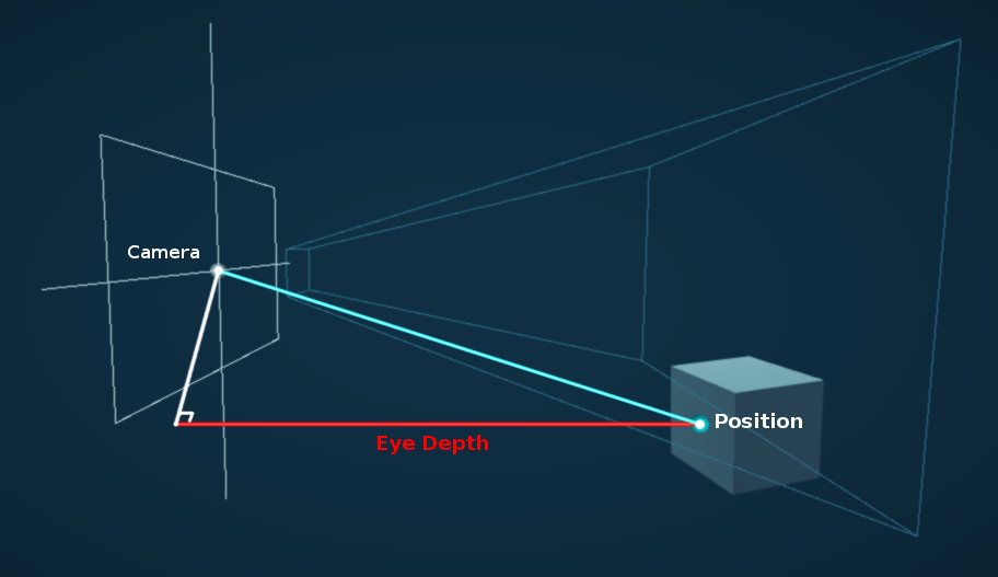
I have a full post about depth related stuff here if interested : https://www.cyanilux.com/tutorials/depth/
Again, i'm not sure i understand this correctly, is this maybe what you are looking for?

yes, this is it
Are you referring to the plane casting a shadow? You could change the Cast Shadows option on the MeshRenderer to remove them
but how can I do it so that the part inside the border is transparent? @indigo frost
i'm sorry for insisting on this, I literally have no experience with shaders and I'd like to learn 😄
no, i am using URP fog shader on the green plane, if i decrease it's alpha the portal is visible. idk why fog shader is affecting the portal shader
i have done a lot of googling and research yet I cannot find any tutorials on a water shader for a sphere, can anyone point me in the right direction? i am a beginner to unity
Oh okay, maybe it's rendering them in the wrong order? Try changing the Render Queue value on the material slightly
Hi!
Is there a simple way to add light/shadow support into a custom vert/frag shader?
I've seen some examples, but the one I'm using is missing ambient/sky and shadows support
More specifically, using Metallic/Gloss
The lightning.cginc seems to have helper methods to do that. Not sure if I can come up with the same structs with a vert/frag shader
Sorry it took me a long time to respond.
You want to make the white area of what i showed into a transparency?
You can shove the output of the last node into a 'One-Minus' and then into the alpha of a transparent shader.
Again... I'm not sure if this is what you are looking for. I can't really help much since I'm not on the pc. Maybe if you can showcase an example from somewhere I'd have a bit more knowledge as to what you are trying to do. Also side note : I'm also not a shader graph expert, but if It's within my knowledge, I'll help you out.
how can i make a 3D scene look like 2D pixel art (WITHOUT just lowering the camera resolution since that looks like shiz)
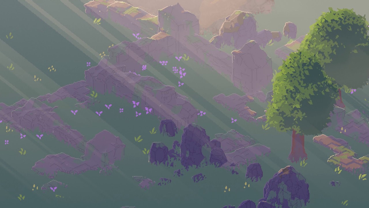
Date of Recording: 2021-01-23
Using the light-space shadow map of the sun, I can project some quads on the scene to compute sunbeams (god rays) with just some texture sampling, without the need to do any raycasting or raytracing. This effect can then be modulated by the camera angle, time of day, and rain density, to create some pretty nice atm...
With a lot of work? Just look through the persons channel (there's a workflow video too), just to get a sense of just how much custom work goes behind it.
You could try asking the author on some pointers for where to even start.
there are a few problems bcs 1. i dont know jack shit about shaders
2. i suck at coding
3. i dont have much time in my hands to write something like that especially as a person who doesnt know anything about shaders
4. im willing to bet the author is too busy to ever respond since ive left a message to him about 2 months ago and he still hasnt responded
also i saw the workflow video i just dont get how that would help me make that shader if i even tried
Okay, so what kind of answer were you hoping for? That maybe Unity had something built in?
obviously unity doesnt have that shit built in but i was wondering if theres anything similiar or something
like a shader i can download and use
or something
Maybe have a look on the Asset Store
but i dont know what exactly to search for
also i cant really afford to pay for anything since im really low on money
the asset store doesnt seem to have anything that could help
Why my Skybox Graph Shader create this defect?

I'll be really surprised if a free solution existed online. I would just look up something like a "3D pixel shader". There's really no official term for this as far as I know.
the only thing i find when searching that is bad tutorials on how to literally jsut lower the camera resolution which i DO know how to do
Right. Well, it might just be that there is nothing available.
I'm just getting into compute shaders, is there any major difference including a custom .cginc vs .hlsl?
guys, so i was making this shader and i wanted a object to fade if it got closer to the camera but this doesn't seem to be working for some reason. Any clue why?

The problem isn't on the object fading the wrong way, the issue is that even if i get the camera closer or further away it simply wont change
i've tried using the position node too and it doesnt change a anything
@regal stag back in February you were talking about the custom Blit renderer feature .. I finally got around to trying it. I got a texture overlayed on the screen, but how do I get the existing camera image so I can apply effects? What you see here is just the texture, it's totally obfuscating the scene

Make sure the Texture2D property Reference is "_MainTex" (field in Node Settings when property is selected. It's different from property name)
Dunno what video it's from but it's very common to have read only buffers
The buffer may be populated by the CPU for example and is readonly in the compute shader
Well you can clearly see that this shader is not writing to the vertices buffer, so there's no reason for it to be a read/write buffer
It's only not RW in this shader
I assume he wrote them
Guess he got that one from https://github.com/ashima/webgl-noise
hi everyone. im starting a tutorial but there is an issue at step one that i have a question about. my graph is missing the properties for 2d texture. any ideas why?

oh i see it on the right, thanks
im getting an error from a URP sprite unlit shader graph and material. the solution i found online is below which is not an option for the tutorial.

the error:
Material 'Load Screen Fader Mat' with Shader 'Shader Graphs/Load Screen Fader Shader' doesn't have a texture property '_MainTex'
the shader works fine, but the error is annoying in the console constantly
You could try changing the "Referance" field in "Transition Texture" to "_MainTex"
or "Fade Texture" whatever you have named the texture equivalent in your graph
thanks 🙂
i coloured my model but its not right how can i make it norma


sgould look like this
can anyone help
it's hard to tell from the pictures alone, are the surfaces not rendering properly? check for reversed normals in your 3D design program or maybe able to flip on import settings.
Secondly looking at your textures you will want to swap from metalic to specular in the material to use same setup as you have imported textures for
i think its backwards i dont have much idea is there anything i can show u
its like the shaders is inside of it and not going round the model
I'm trying to make a little 2d outline shader but I'm having issues with alpha
maybe its because the new shadergraph
https://www.youtube.com/watch?v=MqpyXhBIRSw I'm following this brackeys tutorial

Thanks to NVIDIA for sponsoring!
Learn more about NVIDIA Studio► https://nvda.ws/38AaA8K
Razer Blade Studio laptops► https://www.razer.com/studio
In this video we create outline effect using 2D Shader Graph!
● Learn more about 2D Shader Graph: https://youtu.be/5dzGj9k8Qy8
● 2D Glow Tutorial: https://youtu.be/WiDVoj5VQ4c
● Get Gothicvania Ch...
but at master he has a V4 Color instead of V3 Color + V1 Alpha like mine
(ok I fixed using a split note)
sounds like the faces need flipping, I know it's simple enough to do in Blender to check for and swap back to front faces. If your using other software I'm sure there is probably some methods but I'm no expert 🤷♂️
I think if it's all the faces might be an option on the import settings to do this, depending on model format etc.
i found the model online
what is the format?
I'd probably be looking at downloading blender, import model and fix... however it depends on technical level and how keen you are to resolve this. Blender can handle most formats, not sure what else to suggest though 😉
i thoght that i just didnt texture in properly
nah it's quite a common problem, some programs and importers yield different results depending on format. Many things which can affect, but as you say it looks inside out, probably almost hollow this says it's a model problem not textures.
ahh ok
Can some URP wizard help me?
I'm using ConfigureInput(ScriptableRenderPassInput.Normal); to enable the generation of a normal buffer to use in a postprocessing shader.
I'm also including Packages/com.unity.render-pipelines.universal/ShaderLibrary/DeclareNormalsTexture.hlsl that declares the normal texture and provides some functions to sample&decode it.
If I sample the map using SampleSceneNormals(uv) I get this result:
Are these normals in view space? I don't know a lot about normals...
I need to convert them to world space but I don't know how.
Can I get some help?
what exactly is your end goal?
I want to use it for accurate edge detection for pixelart.
I can use the normal and depth buffers to calculate the position of the neighbouring pixels(assuming that they are part of the same face) and then check if it matches with their actual position. If not then it means that I found an edge
Those look like world-space normals to me. The green is the "up" vector... (0,1,0). Like you'd expect. The red is the vector pointing in the positive X-axis direction. The blacks you are seeing are from negativity.
but when I move the camera the normals change
if they were in world space each face would a constant colour
I couldn't tell if you were rotating the model or the camera.
oh sorry
I'm rotating the camera
also there is no blue
you can't map 2 colours to 3 axis
Hmmm. OK, no world-space normals then I guess. Like you say, must be viewspace.
I take it you're not using shader graph...
nope
What does your vert() look like?
But....you're writing a normals texture somehow, I thought you said. The PP is the one that READS that texture, yes?

here's the definition of some of the functions included in the pipeline
float3 SampleSceneNormals(float2 uv)
{
    return UnpackNormalOctRectEncode(SAMPLE_TEXTURE2D_X(_CameraNormalsTexture, sampler_CameraNormalsTexture, UnityStereoTransformScreenSpaceTex(uv)).xy) * float3(1.0, 1.0, -1.0);
}
float3 UnpackNormalOctQuadEncode(float2 f)
{
    float3 n = float3(f.x, f.y, 1.0 - abs(f.x) - abs(f.y));
    float t = max(-n.z, 0.0);
    n.xy += n.xy >= 0.0 ? -t.xx : t.xx;

    return normalize(n);
}
Last I knew, normals in URP were not supported.
So I thought you were writing them. But it's a moving target.
https://forum.unity.com/threads/urp-normal-texture.873226/
So I'm a bit behind, I guess. AFAIK it isn't supported unless YOU are writing them.
Unity Forum
Hi,
I need the normal texture for a shader in URP and it seems it's not even available in 9.x package in 2020.1b. Is it planned sometime this year ?...
OK, sorry. So your question is : "What format or space is URP's depth/normals texture in" and how to decode it?
yep
Fair enough. I need to find the docs on it if they exist. I'll try to help, but it's new to me too. I have time to learn though and now I"m curious. 1 Sec (or 500).
It's handy to have them and know this.
afaik no docs exist 
Unity has good docs, until you are using something low level or recently added
This: https://github.com/Unity-Technologies/Graphics/blob/master/com.unity.render-pipelines.universal/Shaders/DepthNormalsPass.hlsl
Makes it look like they output worldspace normals.
I'm still confused if that isn't the case.

GitHub
Unity Graphics - Including Scriptable Render Pipeline - Unity-Technologies/Graphics
@fair sleet
IDK what "_GBUFFER_NORMALS_OCT" is or if it is defined. You could test to see if it is defined or not.
In which case it is a packed normal.
Then we "just" have to find the unpack function.
This should be the unpack function right?
It already get's called
Yeah, but you only want that if the define is active. Did you test for that?
And IDK if that is the right function or not, but you're saying it doesn't look like it is working. So...
It is the function used by the SSAO implementation 
IDK. The default looks like world-space to me. What happens if you output just the float3 rgb values? No decode?
One sec I need to return to my PC
Did the SSAO wrap that in an #if? Like #if defined(_GBUFFER_NORMALS_OCT)
I don't think so
// Ref: http://www.vis.uni-stuttgart.de/~engelhts/paper/vmvOctaMaps.pdf "Octahedron Environment Maps"
// Encode with Oct, this function work with any size of output
// return real between [-1, 1]
real2 PackNormalOctRectEncode(real3 n)
{
    // Perform planar projection.
    real3 p = n * rcp(dot(abs(n), 1.0));
    real  x = p.x, y = p.y, z = p.z;

    // Unfold the octahedron.
    // Also correct the aspect ratio from 2:1 to 1:1.
    real r = saturate(0.5 - 0.5 * x + 0.5 * y);
    real g = x + y;

    // Negative hemisphere on the left, positive on the right.
    return real2(CopySign(r, z), g);
}
this is the packing function
as you can see it outputs 2d vector not 3d
the link in the comments is dead btw
The pack is in the source I gave you the link to though. But it is wrapped in an if. So like I keep saying, that has to be active.
GitHub
Unity Graphics - Including Scriptable Render Pipeline - Unity-Technologies/Graphics
_GBUFFER_NORMALS_OCT is not defined
So you likely just have a WS normal and DO NOT want to run it through the unpack.
The trick is to find the wrapper function that decides that and either decodes it or doesn't....so the code is portable.
the plot thickens
the normal texture is generated by rendering the scene using the normal pass of every shader
this is the pass for the urp lit shader
float4 DepthNormalsFragment(Varyings input) : SV_TARGET
{
    UNITY_SETUP_STEREO_EYE_INDEX_POST_VERTEX(input);

    Alpha(SampleAlbedoAlpha(input.uv, TEXTURE2D_ARGS(_BaseMap, sampler_BaseMap)).a, _BaseColor, _Cutoff);
    return float4(PackNormalOctRectEncode(TransformWorldToViewDir(input.normalWS, true)), 0.0, 0.0);
}
as you can see it uses the packing function
The one I'm looking at says this:
{
    UNITY_SETUP_STEREO_EYE_INDEX_POST_VERTEX(input);

    Alpha(SampleAlbedoAlpha(input.uv, TEXTURE2D_ARGS(_BaseMap, sampler_BaseMap)).a, _BaseColor, _Cutoff);

    #if defined(_GBUFFER_NORMALS_OCT)
    float3 normalWS = normalize(input.normalWS);
    float2 octNormalWS = PackNormalOctQuadEncode(normalWS);           // values between [-1, +1], must use fp32 on some platforms.
    float2 remappedOctNormalWS = saturate(octNormalWS * 0.5 + 0.5);   // values between [ 0,  1]
    half3 packedNormalWS = PackFloat2To888(remappedOctNormalWS);      // values between [ 0,  1]
    return half4(packedNormalWS, 0.0);
    #else
    float3 normalWS = NormalizeNormalPerPixel(input.normalWS);
    return half4(normalWS, 0.0);
    #endif
}```I mean.. this is the pass I've took from the package files
OK, but disregard that for 2 minutes. Just output the normal as a float3 without converting it.
See what you get.
Okay
as you can see the blue channel isn't used
bc the packing function only outputs a 2d vector
Yeah, I know.
But this test tells us if it is packed or not.
Because there's an "if", and also because you said that _GBUFFER_NORMALS_OCT is not defined.

@fair sleet I'm leaning towards @meager pelican idea that the Normals_oct is not what your after especially as in the code you linked it states it is for "Octahedron Environment Maps". the SSAO implamantation I viewed does not reference them when unpacking, unless I've overlooked something https://github.com/Unity-Technologies/Graphics/blob/master/com.unity.render-pipelines.universal/ShaderLibrary/SSAO.hlsl
GitHub
Unity Graphics - Including Scriptable Render Pipeline - Unity-Technologies/Graphics
it's also just unpacking within the file half3 GetPackedNormal(half4 p) { return p.gba * half(2.0) - half(1.0); }
If we can find the magic unpack function that's smart and knows how to unpack it regardless of defines we'd be gold.
where did you get this from?
okay
looks like my version has it too
line 380 - 396 shows them grabbing and using
although I will state this, I have used their SSAO and I had to set it to use reconstruct the normals from Depth due to it conflicting with some other shaders. Just a passing warning 😉
And apparently there's, SampleSceneNormals(uv), SampleNormal(uv), and GetPackedNormal(p0) functions.
This is madness
I'm so confused rn
What should I do
I can't find any docs on it yet, all you can do is try those functions or something. Maybe reverse the maths.
But those guys and gals are no slouches, I mean if they write a pack function they write an unpack one somewhere. Getting them to write documentation is probably a different kettle of fish.
You know, programmers. We're all the same. Hate writing docs.
lol.
So I'd try those functions I just listed and see if anything happens by magic.
okay
time to continue banging my head against the wall until the wall breaks ig
sooner or later it will work right?
Sorry man, I was curious too. I mean, it's good to learn the URP has a depth-normals texture.
Sure it will!
thanks
So does anyone know any technique for outlines other than hull inversion or post-process based on depth and normals ?
sobel
thats the second option I mentioned
why not one of these, what are you tryna achieve?
I'm trying to have outlines on objects in the scene that are pretty far away so depth based solutions dont work that well
i mean, in my experience the depth based outline looks like it doesn’t have a very far distance in the scene view but it’s fine in game view
@mental bone blurred buffer outlines or jump flood algo
oh man you summoned mr. outline
On a per-object basis you can draw objects with a ‘silhouette shader’ (just white for example) to a buffer, then you can blur that buffer using box/gaussian (make sure it’s a two-pass effect and you can also downscale the buffer before blurring for extra performance), then you can use that for your outline, the outline will be soft but you can also step() it for a hard outline. Alternatively, use a jump flood algorithm on the silhouette buffer.
But like @brittle owl said you can also just a sobel operator on other things than depth/normals, could be anything really
You can make objects output something to a buffer, then perform sobel on that buffer for outlines
Things like vertex color or albedo come to mind
This here is an URP version of Ben Golus article https://alexanderameye.github.io/jfaoutline.html
Original post here https://bgolus.medium.com/the-quest-for-very-wide-outlines-ba82ed442cd9

ah I was reading that yesterday Thanks for the details 🙂
if anyone could tell me the Lit shader Graph equivalent of PBR Shader Graph's Alpa and AlphaClipThreshold properties i would be very grateful
@ruby meadow you should be able to add them to the master node stack? I think you need to hit space
yea but im using Lit Shader
as pbr doesnt exist anymore
theres only Fragment and Vertex nodes
as the master nodes
and they dont have Alpha or AlphaClipThreshold
Yeah but I think you can add the properties to the lit fragment master node stack, they are not there by default but click on the master stack and press spacebar, I think that does it
you can add stuff to the stack like in vfx graph ?
wait wdym
which master stack
fragment or vertex
Fragment one for alpha clip stuff
it's in the properties I believe when you click the master node
I think you need to enable it from the node settings
Yeah you can pick from a list
hm when i press space alpha or alphaclipthreshold dont come up
click the master node, see settings should be check boxs to enable them

I'm very confused. Sure you can add nodes with space but not the the master outputs right ?
Is it possible that this is different between HDRP/URP? The docs mention clicking spacebar on the master node to add to it
Yeah like 100% sure that I have done this before, add ‘output blocks’ to the master node stack by pressing spacebar, but this is in URP
I dont have a URP project handy at home right now
why would they make it different between pipelines lol
I’m curious, gonna try it out right now haha
I mean I wont be surprised but still
unity needs to get the team that did the vfx graph UX and have them do shadergraph
I tried it out and it's worse than I thought
If you click on the master node and press space, regular node creation menu pops up but there is a thin blue line below the last master stack output and if you click on that first, then press space, you can add output blocks
But in URP I believe that's the only way to add extra output blocks to the stack, I don't see anything related in node/graph settings
what?
PBR was just renamed to Lit
@mental bone btw just as an example, this was done using simple box blur, you can see that it's a softer outline.
I got it working @regal stag tysm
Heyo, does anyone know why the shadowmask makes my shader go dark instead of "brightening" up, like the rest does?
https://i.gyazo.com/51e7f7e185cab2238dffd401ba15c1b2.gif

inputData.bakedGI = SAMPLE_GI(input.lightmapUV, input.vertexSH, inputData.normalWS);
do i need some additional pass for it to work properly?
Maybe I should just sleep on it, but I need some help with a shader.
- I have two points or planes.
- Each of them has a color.
- Based on each pixel's position I want to blend between the two points/colours.
How would someone experienced in shaders go about it?
Here is my (failed) attempt:
https://gyazo.com/9d009a9ad33d6d1e6d0301536a6299bc
The blending is just not correct.
It should based on the distance of the pixel from the lower plane, compared to the distance between the two planes.
Right now I'm just using a manual blending value.
If I do that the it's circular.
Maybe I did something wrong, I'll try again.
That would certainly work.
Let me try that first!
Thanks a lot.
Workin on this dirty water parallax effect, not done yet but cool to get my hands dirty in shader graph
hello im trying to find where to put my roughness map
im using hdrp
from what i found do i put my roughness in the alpha of the metalic map?
invert it and put it in smoothness
I have a cude and 2 txture ground and grass.I want first-half be grass

and second half be ground
How to make it?
My shader is behaving like a standard material for some reason, any ideas? (HDRP)
Or what's best way to make it?
in what part of smoothness like what part of rgb. Or are you talking about the shader graph
yeah I was talking about shader graph. if you're not on shader graph you'll have to put it in the alpha of the metallic or albedo maps
I've posted an issue in #archived-lighting but i suspect its more of a shader thing
I'd generate or look at a vert/frag standard pipeline (I assume that was standard/built-in) shader that's lit, and compare it to yours. Look at the pragmas, spelling of options, and passes. See unity's standard shader sources too. With just a diff, like that how is anyone going to help you?
@meager pelican would it help if i posted the shader code?
atm i've hit a brick wall and the comparisons with other shaders are just making me more confused
I dont even know why thats happening 😆

that material is definitely opaque
OK, so you're in standard, yes?
And you've changed the pass? You should have BOTH a ForwardBase and a ForwardAdd pass.
But like I said, I haven't seen your whole code. And why that light passed through your material as if it wasn't there....is it set to cast shadows? You need a ShadowCaster pass for that.
Or a fallback to a default that has one.
https://catlikecoding.com/unity/tutorials/rendering/part-7/
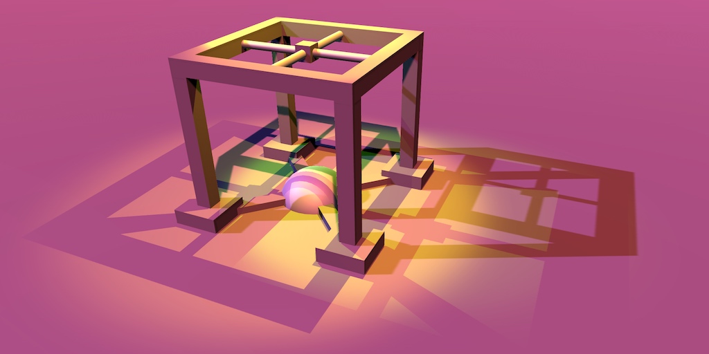
A Unity Rendering tutorial about supporting shadows. Part 7 of 20.
I'm trying to wrap my head around compute shaders. I'm just confused as to how many times the kernel function runs.cs [numthreads(8,8,1)] void CSMain (uint3 id : SV_DispatchThreadID) { Result[id.xy] = float4(1, 0, 0, 1); }In this function, with the dispatch computeShader.Dispatch(0, 256 / 8, 256 / 8, 1);, would this function run 256 * 256 times (so once per pixel)? Or does it run once each group? (256 / 8 + 256 / 8 = 64)
would like to understand numthreads better too
I believe numthreads simply dictates how many threads run per group, so the "ideal" value for this depends on hardware.
However, the amount of times the kernel function runs shouldn't be too hard to understand, I just don't really know how shaders work :p I tried incrementing a value each time the kernel function runs to check, but it didn't even change, so I'm a bit confused
Yeah. OK, so the thread group is 8x8x1.
So that's 64 threads per group.
Yes ^^
So you need to dispatch enough groups in the right way to make them work.
And you do that with dispatch. So in your case
Right, but do you know how many times the kernel function runs? Logically, I would assume 256 * 256, since I'm assuming it has to compute each pixel
You have preemptively a 256 x 256 texture you're running against.
So 256/8 = 32. So it's going to run 32 x 32 groups of 64.
So 1024 groups of 64 threads = 65536, and as a cross-check, you have a 256 x 256 texture so 256^2 = 65536. Check.
?
65536 runs
So it would run the function 64 times?
"the function" is run by 64 shader cores at once, and there's 1024 groups of them. So it would run 65536 times, once for each "pixel" in your 256 x 256 grid, if you allocate it that way. With maths and thread id's and group ids and stuch.
Yes! Massively parallel shader cores running the crap out of things.
Cool stuff.
You want to see them run? And how?
Go into a project and (hopefully standard pipeline) and make a compute shader.
okay
It will generate a text shader.
The default outputs a "red" pixel. and that's it. So you could pass it a render texture and color the pixels, then blit it to the screen.
But instead of red, color it with some math. Like GroupID and ThreadID as fractions of 64 or height and width. And watch it fill in the squares. I guess I could work on a demo if you want, but will take a bit.
lool
great idea
i will make that, no worry
i was thinking about training some shader writing
There's more info here on what gets passed to individual threads, several variable semantics:
https://docs.microsoft.com/en-us/windows/win32/direct3dhlsl/sv-dispatchthreadid
Indices for which combined thread and thread group a compute shader is executing in.
^ Yeah this is super useful, I read this and it answered my question

Is there a way to get the constant 4294967295 (uint's max number in HLSL and C#) as a constant in HLSL?
Ok so this issue definitely has to do with mixed lighting
When i disable mixed lighting, the soft shadows that appear beyond the cascade get turned off, including the shadow that is applied to the grass
But i don't want to disable it, so i'm still looking for a solution
If it isn't already defined, try
uint myUInt = UINT_MAX;```I'm trying to use this tune shader in VR via XR and only getting rendering in my left eye. Any ideas or fixes? https://github.com/IronWarrior/UnityToonShader

GitHub
Source code for Toon Shader tutorial for Unity. Has specular, rim lighting, and can cast and receive shadows. - IronWarrior/UnityToonShader
What does this error mean?
I'm setting Result (which is a render texture) in two different kernel functions that are being dispatched right after one another. Could that be a problem?
It's complaining about the kernel at index 1, not 0. If that helps any.

This is the kernel at index 1. The error seems to be complaining about the usage of Result, which is a render texture that gets set in kernel 0.
Oh. 😉 It's telling you you can't do that. Kernel 1 is thinking that Result[] is an OUTPUT texture, and it wants you to set it.
How is Result defined?
RWTexture2D<float4> Result;
And this is kernel 0:

It basically just does a bunch of stuff and then sets the value of Result
0 is not the problem, though.
So that's good.
But for 1, you want the input texture to be what you had written in 0. And the output is to your new texture (ProcessedResult). Right?
So think of it this way:
Call them "InputTexture" and "OutputTexture"...for reference.
Yep. I'm basically setting certain pixels on the screen to white in kernel 0, and then reducing their "intensity" in kernel 1.
So when you write the C#, you'd set inputTexture to whatever or null I suppose if you don't use it. Or a dummy texture, whatever works, and output texture as Result.
And then when you make the call to kernel 1, you set the Result from kernel 0's texture to be input, and the processedResult texture to be the output.
Yeah but I still need to modify the input texture inside of the shader
So I'm trying to write a shader that I can use in a game called VRChat. It uses unity 2018. What I'm trying to do is write a shader that manipulates my view inside of an object that turns everything from full color vision to red-green colorblind. I'm having issues with knowing what a shader like such would be called so I can research it
Shaders have to be set up to do single-pass stereo rendering. Might work to disable that and use double-pass stereo, but ouch.
I thought that would be it. so it would tax the framerate a lot?
I tried putting the contents of kernel 0 and 1 in the same function, and it's still giving me the error.

It's double the draw calls, yeah. But maybe not all that bad depending.
I didn't really understand what you meant by it complaining that result isn't an output texture. I'm still setting it
Actually, this time, it's saying ProcessedResult isn't set
Which is what I'm doing at the last line
In kernel 1, you're setting processedResult[]. But reading Result[]
Right, but I combined them and now both textures are being set, and it still seems to be complaining about processedResult
Well, we actually made progress. Now it's complaining about the right texture. lololol.
What do you mean you "combined them"?
I took the code from kernel 1 and put it inside of kernel 0. So the first picture is the only function in the shader.
This time, maybe it's complaining because I'm setting 2 different textures in a single kernel?
Actually, I fixed it
Well I mean
It doesn't work, but at least the error is gone lol
Basically you can do it like you started to, or you can do whatever it is you're doing now.
Buuuuut....you have to make sure to set your inputs and outputs up and keep them straight.
And flip them around between kernels if necessary.
aka double-buffering.
unity really doesnt like me

i wanted to see if adding a shadowcaster fixed the shadowmask problem, but to no luck... because the shadow.hlsl file doesnt work
Might need #include "Packages/com.unity.render-pipelines.core/ShaderLibrary/CommonMaterial.hlsl" before the Shadows.hlsl include. That's where the LerpWhiteTo function is located.
I did that
But that shouldn't matter, as the file gets included in shadows.hlsl too
I don't think it does
And when I paste the function in manually, it says redefinition
Plus the function not found error
I'll see if I missed something tomorrow, already shut down my computer
Tho, while you are here, I wanted to ask if you know anything about my shadow mask issue
It might be that when Shadows.hlsl is included, the function doesn't exist so errors. But later the CommonMaterial.hlsl is being included causing the redefinition. Instead of copying the function out, it would be better to use the include.
Oh, maybe implemented the include after the shadows include...
Darn c Syntax and it's top to bottom compilation
As for the shadow mask thing, I figured out it has to do with mixed lighting, but not much more
Still stuck there
Not too sure, I don't have much experience with the Shadowmask but looking at the code you posted before, it had the SAMPLE_SHADOWMASK for the InputData and is using UniversalFragmentPBR function so I'd assume it would handle it automatically. Seems weird that it would darken at a distance.
I guess make sure you have the correct keywords too, like
#pragma multi_compile _ LIGHTMAP_ON
#pragma multi_compile _ LIGHTMAP_SHADOW_MIXING
#pragma multi_compile _ SHADOWS_SHADOWMASK
looking for some ideas on how to get rid of these strane diamond shapes when dithering. I cant see them in edit mode. only in play mode.


Will do, thanks!
Oh, and one last thing
The batching process doesn't allow for submeshes to have multiple materials
It removes them on build /play
I'm trying to take a RWTexture2D variable in HLSL and "copy" it so that another RWTexture2D variable now has the exact same pixels, except they're not the same texture. How do I do this?
Hmm that's kinda annoying. I guess a workaround is to just duplicate the GameObject itself. (Or use the RenderObjects feature)
@fringe sigilThat's generally referred to as a "blit".
https://docs.unity3d.com/ScriptReference/Graphics.Blit.html
So, I am learning basic vertex/fragment shaders in Unity after months of not doing anything, And I want to set up a simple lighting shader without using Unity's surface shader. I have set up a super simple shader using normal directions, but because the lighting is based on a direction, and not position, I get some unwanted lighting behavior.
Here is the shader
{
    Properties
    {
        _MainTex ("Texture", 2D) = "white" {}
    }
    SubShader
    {
        Tags { "RenderType"="Opaque" }
        LOD 100

        Pass
        {
            CGPROGRAM
            #pragma vertex vert
            #pragma fragment frag

            #include "UnityCG.cginc"

            struct appdata
            {
                float4 vertex : POSITION;
                float2 uv : TEXCOORD0;
                float3 normal : NORMAL;
            };

            struct v2f
            {
                float2 uv : TEXCOORD0;
                float4 vertex : SV_POSITION;
                float3 normal : NORMAL;
            };

            sampler2D _MainTex;
            float4 _MainTex_ST;

            v2f vert (appdata v)
            {
                v2f o;

            o.normal = mul(v.normal, (float3x3)unity_WorldToObject);
                o.vertex = UnityObjectToClipPos(v.vertex);
                o.uv = TRANSFORM_TEX(v.uv, _MainTex);
                return o;
            }

            fixed4 frag (v2f i) : SV_Target
            {
                return saturate(dot(i.normal, _WorldSpaceLightPos0));
            }
            ENDCG
        }
    }
}
Does anybody know how I could use the location of lighting to illuminate objects so I don't get unwanted behavior? (Or just any way to do this)
I had the idea of making a custom light position, but that seems difficult if I wanted to change the position while the game is running.

Firstly, you need to transform the normal direction similar to the way you transformed the vertex location. So it rotates and such.
There's a macro for that. Sec.
I guess it is a function:
inline float3 UnityObjectToWorldNormal( in float3 norm ) you can call that comes from UnityCG.inc.
You will also want to see here:
https://docs.unity3d.com/Manual/SL-VertexFragmentShaderExamples.html
Modifier that redefines a function declaration. inline is currently the only modifier value. The modifier value must be inline because it is also the default value. Therefore, a function is inline regardless of whether you specify inline, and all functions in HLSL are inline. An inline function generates a copy of the function body (when compiling) for each function call. This is done to decrease the overhead of calling the function.
From : https://docs.microsoft.com/en-us/windows/win32/direct3dhlsl/dx-graphics-hlsl-function-syntax
Um, basically ignore it. It's telling the compiler to insert the code rather than doing a function call, but many compilers do that anyway. 😉 HLSL loves inlining code and it makes sense for a GPU. It will unroll loops too if it can determine the loop counts. So instead of doing a loop it will just duplicate the code 4 times or whatever the loop count is. It's compiler stuff.
Code generation.
thx
Cyan beat me to it. lol
https://www.youtube.com/watch?v=6_-NNKc4lrk
The video I got the code from is there, and doesn't the line o.normal = mul(v.normal, (float3x3)unity_WorldToObject); basically do the same thing as what you sent or no? I'm pretty new to all of this so it's a bit confusing

Support me on Patreon ➜ https://www.patreon.com/DanMoran
Follow me on the Twittersphere ➜ https://twitter.com/DanielJMoran
Get the Assets for this Video here ➜ https://github.com/Broxxar/NormalMapping
Music:
Donkey Kong Country: Tropical Freeze - Stickerbrush Symphony, 2014
David Wise & Kenji Yamamoto
Yes
But use their routines to future-proof your code.
Doing "manually" is less portable.
Makes sense
I'm also a little confused about the original question. What exactly is the unwanted lighting behaviour here? That it's using direction? It's a directional light so that's how it should look, no?
Yes, That is exactly what it is programmed to do. However, what if I wanted positional lighting instead, what would I do for that
It's more like "in addition to" rather than "instead". Here this will help:
Yes, that's what I mean, whoops
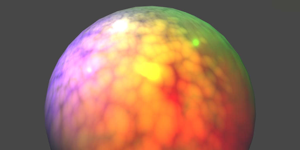
A Unity Rendering tutorial series about supporting multiple lights. Part 5 of 20.

A Unity Rendering tutorial about performing PBS lighting. Part 4 of 20.
Beat me to it 😄
😉
So, before I read that I had an idea and I have no idea if it would work. Basically, I would get the position of the light and subtract that from the position of the normal (it would probably be the vertex actually, idk) and if the value is greater than 0, it would be lit
IT's a dot product.
Often referred to as N dot L.
Where N is the normal vector, and L is the light direction (might be negated or not, I'd have to try it).
That's for simple lighting.
Yeah, and that's what I used for the directional lighting, but for positional I would need the position
There's more for other more complicated things, like specular (gloss) lighting. Blinn-Phong, or even PBR.
They include more sophisticated per-pixel calcs
Like energy conservation.
And/or view direction of the camera.
To calc highlights.
Yeah, right now I just want to make a custom toon shader using my own lighting and stuff
I'll check that out, thanks for the recource
🙂
It's easiest to use a surface shader, but this is more educational.
So you know what it is doing.
Yeah, might be easier, but for my sake I want to learn how it works
Or if you're masochistic.
^ yep that's me
lol
Thx for the help, hopefully I can get somewhere. If not, I'll come back here 😛
P.S.
There's custom lighting in surface shaders too.
https://docs.unity3d.com/Manual/SL-SurfaceShaderLighting.html
So you don't have to do all those damn passes yourself manually. Just FYI.
@wary jackal
cull off isnt working, i cant see the inside of my mesh
i didnt write this shader but i watched an explanation on it, it might be outdated by now idk
@meager pelican I haven't looked into it much, but I just don't get how surface shaders work with vertex/fragment shaders. It confuses me how two functions can be squished into one surf function
nevermind it wasnt a shader issue, it was a problem with my scaling (setting a scale to -1 does some weird things)
Surface Shaders just generate code for vert/frag shaders
so the thing that ends up running in your game are normal vert/frag shaders. Unity just does some magic to generate those shaders from the surf shader
Is it worth it to learn about matrices in regards to shaders?
The tutorial you sent has a lot about matrices and I have no clue what it's talking about
Yeah, it can be confusing as to what goes into the generated vert() vs what goes into the generated frag(), but overall it figures it out based on what you're messing with. And it tries to do things that make sense to do in the vertex() per vertex. Such as that normals calc we were discussing. That's pure vert since you want to do that as few times as possible and the normals are stored with the verts, basically. Like same counts. Although you can have per-pixel normals with a normal map.
Something to read up on. But mostly you just use the functions that use them and don't worry too much about 4D math.
@meager pelican okay, I believe the first page of the tutorial you sent has some stuff about matrices
Matrices do translation, rotation, scale. in one multiply operation. Conversion between spaces. Like object space to world-space. Etc.
It's basically the transform component idea from a game object, but it's all vector mathed up.
Ah okay. So should I just ignore when it talks about matrices, seeing as Unity handles all of that
Kind of. You'll have to at least use them in the macros. For now, you can't learn everything at once, and matrices make your head hurt. 😉
I seldom have to construct a matrix manually, and if I do, I google my butt off.
Other times you have to use an inverse matrix for something. Because you're reversing a concept. But you'll get into all that later.