#archived-shaders
1 messages · Page 201 of 1
i think its due to depth buffer
the cameraobject became completely useless
its the third bug i had with depth buffers. also: the property binder script is completely useless for me
Hey guys, can anyone tell me where am I going wrong? I see the matcap texture as pixelated on android build while it works fine in editor. Apparently it seems like UV precision glitch but couldn't find where I went wrong.

Thanks, I'll have a look at JetBrains then
Pretty irrelevant question, but how are shaders executed? Does the shader program run for all triangles of an object in parallel or does it run triangle after triangle? Or is it a mixture and per clock on the GPU as many triangles as possible are calculated until all of them are calculated?
How do I get an output from a compute shader?
I'm very new and can't find a tutorial explaining how to get an output
You can get data back from a compute buffer: https://docs.unity3d.com/ScriptReference/ComputeBuffer.GetData.html
it's not going to be very performant though
in a compute shader, would it be better to have 1 large structured buffer, with a larger struct that defines it, or would it be better to split it into 2 structured buffers, with smaller structs for both?
hey guys, not sure if this is a shaders problem and probably is a really stupid one... I was trying to make some of my UI buttons fancier by adding a material but whenever I add one the button turns full black or just doesn't show the material right. I have searched on google, there are a lot of topics about this, tried many things but none work... I am really desperate something so simple and I've wasted so much time already. Anyone got any clue? really appreciated... thanks

anyone know how to get nodes in shader graph to snap into alingment, it sais in the productboard it is implemented and the blue lines show up but the nodes dont snap to them

Currently available from 2020.2.0a21 / 10.0.0-preview.27 package on.
As you drag a node, it will snap to other nodes (on the X and Y axis) in your graph to allow cleaner layouts.
I think it's meant to do it automatically, or at least it does for me in 2020.3 if I'm remembering correctly.
for some reason it doesn't work for me on any project on any version of unity

Normal maps should be connected to the Fragment's Normal (Tangent) port instead of vertex. (Assuming you're using a Lit shader graph)

If it's an unlit graph, why do you need a normal map?
Where could I change that to have the voronoi effect colored ?

To have it looking like this :

instead of this :

Here it doesn't change anything :

And here it changes the whole color :

I would use a Lerp, with A set to the texture's RGBA output, B set to the Color property, and T set to the black/white mask showing where the Voronoi should be.
Lerp(sample texture RGBA, (color), voronoi)

hey, ive got a bit of a problem with my shader
multiply the voronoi by the color's alpha (use the A output of a split node)
ive made this cube in blender, and my plan is to normalize the vertices in a shader to make a sphere, and use a lerp to blend between cube and sphere

sounds pretty smart on paper right?
for whatever reason, though, normalizing the vertices causes this:

what could be happening?
It canceled the effect

and change the color's alpha value (it defaults to 0 for some reason)
How do I do that ?
select the color property and change the default value
Oh thanks!
Anyway I change this :

to this ?

It's not really an outline and I don't really know how to call it to search on google/youtube
@hazy sage vignette?
Oh yeah thanks ! How did I not think of it
I can't find any tutorial xd
Found a way! The fresnel effect
maybe you can translate one of the effects from shadertoy? like https://www.shadertoy.com/view/4sB3Rc
Fresnel Effect isn't what you want, that is based on normals & view dir.
You can use a Distance node with the UV and a Vector2 set to (0.5, 0.5) to get a radiual gradient like that.
Oh I'll try that thanks
I was about to ask why it didn't work, when I saw you saying that fresnel is not what I want x)
oh, it doesn't work with tiling
@regal stag How could I change that ?
I have this

Eh, I'm not really sure why it's cut off like that (is the Vector2 using the correct value of (0.5, 0.5)?
Also not too sure what you actually want to achieve either, before you just showed a radial gradient over a single tile. If you want it to outline multiple tiles as a group that's not easy.
(is the Vector2 using the correct value of (0.5, 0.5)?
Yep
I'm following the art of code's tutorial on ray marching and I don't understand this function that calculates the normal on a given point:

get_distance is the distance function and returns the distance to the object as a float
why would he subtract a float3 from a distance to get the normal?
wouldn't that have to be:

?
@regal stag I would like the shader to achieve something like this :

Not really an expert on raymarching, but the idea is to compare the distance field at the point p with similar points offset slightly in each axis direction. Subtracting the two distances basically gives you a sort of gradient/derivative to approximate the direction of the normal.
(This uses a similar idea too, but offsets in both directions : https://www.alanzucconi.com/2016/07/01/surface-shading/#step2)
Cyan? xd
Yeah that's not really something you can do in a shader. The data about where the edges are would need to be passed in through additional UV data or vertex colors.
Personally for something like this I'd look into creating a tilemap (as in, having the gradient/edge baked into the texture, providing multiple tiles that can be drawn, rather than just a single repeating one). e.g. https://blogs.unity3d.com/2018/01/25/2d-tilemap-asset-workflow-from-image-to-level/
Good evening everyone, Is it possible to have a sprite that completely occludes everything behind it? pretty much making an invisible hole to anything that is occluded by it? need this to implement an "erasing" feature in a transparent drawing board
My use case: I have a CanvasCamera pointing at a RenderTexture, i instantiate sprites in front of it to "draw" stuff, over a transparent texture, and i save that into a material after so many instantiated brushes, but now i need to be able to "paint transparency", i tried reading and setting the pixels alfa but it seems to expensive performance wise. so i'm trying to use the same idea of instatiating a brush (sprite) but have it somehow subtract everything that is behind it from the CanvasCamera
you could try to sample the texture that generates the mask in a lower mip map value , that would blure the texture and probably soften the edges
I just "downgraded" my project from 2021 back to 2020.3.7f1 for DOTS reasons, and now I'm not getting runtime recompilation/hot reload of a compute shader so I have to keep exiting play mode and restarting it to see changes made - I thought hot reloading was still a thing in 2020 wasn't it?
Hmm it works if I refresh the .compute file in the project window, that's better than having to restart play mode!
Did you get an answer? What pipeline are you in?
http://mathproofs.blogspot.com/2005/07/mapping-cube-to-sphere.html
Here's an article, but you have to realize that he's talking about a cube with a length of 2 units per side (-1 to +1) for each dimension. So change your cube to be 2x2x2 with origin in object space at (0,0,0).
Then here's a sample vertex function:
        void vert(inout appdata_full v) {  // Called for object-space.
            // we don't touch the size/scale of the original cube mesh.

            // Math is from http://mathproofs.blogspot.com/2005/07/mapping-cube-to-sphere.html
            float x2 = v.vertex.x * v.vertex.x;
            float y2 = v.vertex.y * v.vertex.y;
            float z2 = v.vertex.z * v.vertex.z;
            float3 s = float3(
            v.vertex.x * sqrt(1. - y2 / 2. - z2 / 2. + y2 * z2 / 3.),
            v.vertex.y * sqrt(1. - x2 / 2. - z2 / 2. + x2 * z2 / 3.),
            v.vertex.z * sqrt(1. - x2 / 2. - y2 / 2. + x2 * y2 / 3.));
            float3 sphereNormal = normalize(s);
            float3 sphereVert = sphereNormal * _Radius; // extruded/scaled vert
            v.vertex.xyz = lerp(v.vertex, sphereVert, _RoundnessPct);
            v.normal = lerp(v.normal, sphereNormal, _RoundnessPct);
        }
Including reference/credit to the site shown.
It has _RoundnessPct and _Radius as shader defines coming in.
You can duplicate that in Shader Graph if you want with relatively little effort, if you're in another pipeline. This one is from a surface shader that has a custom vertex function.

After the last post , I got to thinking about how to come up with a mapping from the cube to the points in the unit sphere. In the last ...
Scale it all using the game object's transform, if you want to scale it. You might want to change the way the radius works relative to object-transform scale, depending on needs.

Unity
Unity is the ultimate game development platform. Use Unity to build high-quality 3D and 2D games, deploy them across mobile, desktop, VR/AR, consoles or the Web, and connect with loyal and enthusiastic players and customers.
See "builtin shaders" in the appropriate drop-down box.
@grand jolt
It has cginc files in CGIncludes folder, but shaders are also included in the DefaultResourcesExtra folder.
In the built-in shaders downloaded from that link Carpe posted.
was watching a tutorial today and think I may have spotted what you're looking for, a lerp node, like at 4:00 in this vid:
https://www.youtube.com/watch?v=eZqd68YaY2U
Hi guys, i'm new here and i'm having an issue, i have followed this tutorial https://www.youtube.com/watch?v=dyiLJ1PFhM0, but shadows are not casting on the toon shader. The guy in the video said it's an issue with URP but i didn't understand the way to fix it. my unity version is 2019.4.8f1. Would be nice if someone could help

The Legend of Zelda Breath of the Wild has a beautiful aesthetic, characterized by the use of cel-shading.
Today we try to recreate his shader on Unity.
Repo:
https://github.com/ToughNutToCrack/ZeldaShaderURP2019.4.0f1
Roysten analisys:
https://roystan.net/articles/toon-shader.html
Sketchfab plugin for unity:
https://github.com/sketchfab/unit...
I have some better custom lighting functions/subgraphs here that work properly with shadows. It's split into two subgraphs : Main Light and Main Light Shadows, but they should be the same inputs/outputs. https://github.com/Cyanilux/URP_ShaderGraphCustomLighting
does anyone have an example of compute shader with texture sampler?
for game asset, is it common to not unwrap and set the mapping on the engine or is it much better if everything unwrapped?
Ive started work on a 4D mesh renderer within Unity, it displays individual 3D slices of 4D geometry, but its pretty slow, roughly .0032seconds, or 1/5th of a frame for just a 4D cube, and was wondering if compute shaders would be a viable way to generate real time meshes
I'm using Shader Graph with HDRP to create a Lit shader with a wind effect. It's working great, except that the lights I have in my tent are shining through to the exterior of the tent, which I don't want. This does not happen with the standard HDRP Lit shader. Anyone have an idea what might be causing this? Thanks for any help!

I'm gonna try this and see, thank you man
Solved this by piping my normal map into Normal From Texture. In the end it was a normal map problem.
Good evening everyone, Is it possible to have a sprite that completely occludes everything behind it? pretty much making an invisible hole to anything that is occluded by it? need this to implement an "erasing" feature in a transparent drawing board
My use case: I have a CanvasCamera pointing at a RenderTexture, i instantiate sprites in front of it to "draw" stuff, over a transparent texture, and i save that into a material after so many instantiated brushes, but now i need to be able to "paint transparency", i tried reading and setting the pixels alfa but it seems to expensive performance wise. so i'm trying to use the same idea of instatiating a brush (sprite) but have it somehow subtract everything that is behind it from the CanvasCamera
Try turning blend off in transparent queue, and writing (0,0,0,0). That will probably require a different shader for that purpose.
If that doesn't work, and if you cannot write transparency any other way, you can always use a stencil to flag what you want to clear and blit to another pre-cleared transparent texture, skipping stencil areas, and then swap textures., and continue on. Swapping again when needed.
That seems like a lot of work, but if you're in opaque you cannot write to the transparent alpha that I know of. And if you're in transparent, you may need a special blend or these other techniques.
I suppose another way is to always composite layers, having a 0,0,0,0 background, or even a static color (so not a real layer) and then have a mask layer for erasing, and then stacking other layers on top. Or have each layer have its own mask layer.
Spitballing.
how would i go about adding a bloom to a 2d pixel art sprite?
i want to be able to create a glowing green outline on a sprite to highlight it
used a 2d light for that ^
There is a complex lit shader that uses a height map use that one
I have one problem , that was after setting aniso level to 0 my Fps raise from 40 to 60 but my texture get blur , so I want my texture quality should be nice and also I want to aniso level to 0 , so there is any other ways do it in shader like texture2dlod or some other thing?
Well if you dont want use the complex lit shader with a build in height map you need to sample your texture and add the values from it to the vertex position and feed that result into the position part if the vertex stage
If you want to use parallax offset the supply the texture sample as the height in that subgraph and add the output to the uvs of your other texture sampling
Is there a tutorial somewhere showing me how Unity builds a scene with Forward Rendering? I'm having issues getting a multi-pass shader I'm working on in Amplify displaying some weird shadow artifacts, but I can't find any documentation explaining the order stuff is rendered in Unity in detail, so I don't even know if the shadows are being rendered all at once in a pre-pass, or in a post pass after the albedo for each individual object in front to back order, or if transparent objects are drawn back to front but opaque objects front to back, and then lighting is rendered on top of them, and then shadows on top of that. I have absolutely no clue what order any of this stuff is being drawn in and the docs are no help. The only thing they describe in the second on the Forward Rendering path are what mode lights are rendered in if they're set to important or not important, but it makes no mention of shadows. https://docs.unity3d.com/Manual/RenderTech-ForwardRendering.html

Hey all, is there anything I have to do to get a shader graph to contribute and receive global illumination in URP? Haven't done a huge amount of testing yet but hoping there's a gotcha i haven't considered before I go and replicate in a clean project
using lit master node
Actually, it looks like baked lights are baking onto the shader, but none of the emissives are
I think if you switch the inspector into debug mode, you can edit the Lightmap Flags setting on the material to "2" which should correspond to allowing emissive to contribute to baked GI.
Or can set Material.globalIlluminationFlags through C#. A Custom Shader GUI usually handles it.
https://docs.unity3d.com/ScriptReference/MaterialGlobalIlluminationFlags.html
Yeah, I've tried that, thanks. It was about the only direction I could find googling, but it didn't seem to make a difference
Just tell one thing how to make shader like I want to display high clarity image within 50 m and low clarity image after 100m
hello everyone
i have a very dumb question
how do i add a texture that i downloaded from cco textures to unity ?
How can i access the color property in shader graph? if i click on plus and choose an option i can only give it a name

so if I have a compute shader that renders to each pixel of a texture, each pixel requires say X function to be called Y times
Now lets say every time X function is called, it increments a number special to that pixel(so it counts how many times that function is executed)
Is there a way for me to get the TOTAL number of times that function is called across ALL pixels?
hey how can i add a bump map to this

this is probably trivial, but i'm getting a weird artifact on one of the pbr shaders i decided to mess around with tonight. It looks fine in shader graph, but has a weird blue line ingame
https://gyazo.com/7461a232f3c216436f13ddacc9b1c241
https://gyazo.com/8099032fae8ba4651c9cc8926fc8ad04


i have a feeling its something to do with with one-minus but im not sure
It's caused by alpha values going into negatives. Can use a Saturate node before connecting it to the alpha port to clamp it between 0 and 1
Ahh I see, thank you, never used that node before
The surface shader examples page has a bump/normal map example which should help. https://docs.unity3d.com/Manual/SL-SurfaceShaderExamples.html
In v10+ the settings for each property was moved to the Graph Inspector window, Node Settings tab (while the property is selected in the blackboard or graph that is)
@regal stag thanks mate, i found it 🙂
Anyone know where I can get the doctrina fur shader, The website link is broken on youtube, and I can't find it anywhere else.
hey, any ideas why this doesnt work:
struct vertices
{
    float3 verts[6];
    uint vertCount;
    void Add(float3 a)
    {
        verts[vertCount] = a;// Error Here
        vertCount++;
    }
};```Shader error in 'TetrahedralizeCompute.compute': array reference cannot be used as an l-value; not natively addressable at kernel Main at TetrahedralizeCompute.compute(20) (on d3d11)I'm having some issues with self-shadowing on transparent objects. Is it possible to adjust the bias and normal bias on a per-shader basis? If I adjust the global values for my directional light I have to make them pretty high to remove the artifacts, but it causes shadows to not be pinned to objects on the ground any more, so I want to adjust it more on my transparent objects than on the rest of my stuff.
I've attached the shadow caster pass for my shader. Also, I've made this in Amplify, so if there's a way to do this within Amplify instead of editing the shader code directly, that would be useful!
i have joined this server with the express purpose of asking why this basic depth buffer read isnt working
    SubShader {
        Tags{ "RenderType" = "Opaque" "Queue" = "Geometry"}

            Pass {
            CGPROGRAM
            #pragma vertex vert
            #pragma fragment frag

            #include "UnityCG.cginc"

            struct appdata
            {
                float4 vertex : POSITION;
                float2 uv : TEXCOORD0;
            };

            struct v2f
            {
                float2 uv : TEXCOORD0;
                float4 vertex : SV_POSITION;
            };

            v2f vert(appdata v)
            {
                v2f o;
                o.vertex = UnityObjectToClipPos(v.vertex);
                o.uv = v.uv;
                UNITY_TRANSFER_DEPTH(o.uv);
                return o;
            }

            sampler2D _CameraDepthTexture;

            float4 frag(v2f i) : SV_Target
            {
                float depthValue = LinearEyeDepth(tex2D(_CameraDepthTexture, i.uv).r);
                float4 depth = fixed4(depthValue, depthValue, depthValue, depthValue);

                return depth;
            }
            ENDCG
        }

    }
    FallBack "Diffuse"
}```aaand here's my camera's script
using System.Collections.Generic;
using UnityEngine;

[ExecuteInEditMode]
public class CustomRenderPass : MonoBehaviour
{
    public Material TestMaterial;

    void Start()
    {
        GetComponent<Camera>().depthTextureMode = DepthTextureMode.Depth;
    }
    private void OnRenderImage(RenderTexture source, RenderTexture destination)
    {
        Graphics.Blit(source, destination, TestMaterial);
    }
}
sorry to ask people to read code, but ive scrounged around so much, and everything is so inconsistent because of all the changes to this stuff over the past few years, and I just can't get it ironed out
as of right now, depthValue which should return the texel's depth buffer value, is just returning a constant, so my screen is a solid grey
i think that it must be something to do with either my camera's script or some global project setting which causes the depth buffer to just not work
Do you have a directional light in your scene? Creating one will force Unity to create a depth buffer. I don't think it will unless you force it to. You can make the light really dim if necessary.
Hey guys. I'm currently working on a psx era inspired horror game in the vain of silent hill 1 and I'm using the psx retroshader provided by dsoft20.
However, I seem to be running into an issue with white lines appearing between faces on the mesh of my level's map.
As was common in the era, I'm utilizing a number of texture atlases, created in gimp, for texturing purposes to save on file size. Each map is made up of an 8x8 grid of 32 bit textures, reaching a total image size of 256 x 256. When importing these atlases, I've made sure to disable the generation of mip maps / aniso filtering, turned the filter mode to point, and set the wrap mode to clamp.
I'm modeling all assets in blender and have been sure to remove all double faces / vertices as to ensure that there are no seams that could be causing the issue. Furthermore, the lines seem to only appear whilst the psx_retroshader is active. Specifically the vertexlit iteration.
Any idea what could be causing it or how I would fix the problem?
Here is a link to dsoft20's shader on his github page: https://github.com/dsoft20/psx_retroshader .
Here is the gif of the issue occurring in my game (It's most noticeable on the road to the right of the placeholder character):

GitHub
Shader that "emulates" the rendering style of ps1. Contribute to dsoft20/psx_retroshader development by creating an account on GitHub.

Haven't tried it myself, but the URP particle shaders use this function : https://github.com/Unity-Technologies/Graphics/blob/2010bda30b0bb94f25e6fc5e03530f559554d75c/com.unity.render-pipelines.universal/ShaderLibrary/Particles.hlsl#L85
I think the near and far parameters is basically a Vector2 property to control the fading
projection is the Screen Position node (Raw mode), and sceneZ is the Scene Depth node (Eye mode).
Hopefully that helps
Thank you Cyan
If I were you, I'd change the vert() function's use of the macro and the name of the float2 uv, to float2 depth.
It's not a UV, it's a depth. Less confusing. Besides you're probably clobbering the uv value. Which might be your problem, since you use it in frag().
Next, see definitions and example here:
https://docs.unity3d.com/2019.3/Documentation/Manual/SL-DepthTextures.html
The macro you're using in the frag() will get the depth info currently stored in the depth-buffer but that's NOT the one for the current object you're rendering. It's the depth "behind" what you're rendering.
That may or may not be what you wanted, IDK.
I want to blur the screenspace shadow, how to choose the blur weight ?

anyone knows how to make a blend between two game objects that have meshes in them? the example I found above is from Sebastian Lague's raymarching tutorial but he used shapes which isnt really what I am looking for
You're going to have to specially craft the meshes to do that, have the same number of verts or something, in the proper order, then maybe you can "morph" them with a lerp. Guessing, haven't tried it.
hm sounds interesting, thanks i'll try
upgraded my project ot urp and everything seems to be fine but when i apply a shader (made for urp!) to my materials they turn pink in game view even tho the asset view hs them working fine o(-(

im also getting this error which i didnt get when i played around with this yesterday
To me it just looks like your include syntax is wacky or something with the file path for your included HLSL script is wrong.
When upgrading your project is it possible that the file path changed or your project just hasn’t registered the files current location?
Did you upgrade your materials to URP? What version of URP? If it is past 10.0 then all HLSL (used in shadergraph custom node at least) must use #define rather than #def
There are other guidelines here: https://docs.unity3d.com/Packages/com.unity.render-pipelines.universal@12.0/manual/upgrade-guide-10-0-x.html
@oblique hornet
ah maybe? i didnt mess with any of the code (im doinh visual scripting) so i can go thru and fix that if needed. just upgraded to unity ver 2020.3.8f1 so idk if that affected it, or exactly what urp ver im using
oh and yes i did upgrade my mateirals but it didnt look like it did anything so ill try again tonight djdjf
@sinful shuttle @meager pelican thanks to both of you for the insight, but apparently the issue was fixed by a full restart of my computer. guess I should have pulled out all the stops before coming here. I thought for certain it would be the directional light thing, since my scene doesn't have one, but apparently not.
and carpe, could you elaborate on the specifics of the macro im using in frag? did you mean UNITY_TRANSFER_DEPTH in vert? or is LinearEyeDepth a macro?
additionally, what's your opinion naming conventions for a shader which uses both the main render texture and the depth buffer? I understand using depth in my case, but if I expand the shader to include the maintex it becomes confusing again.
Greetings all, I am looking for a shader that will take a sprite and sort of diffuse/disperse it like a shadow. Essentially instead of having hard edges, somewhat soften and spread out the pixels to give it blur
anyone have any ideas on what to call this so I can search for one?
If you have any custom function nodes in shadergraph that are set to file mode (aka using a HLSL file rather than writing the code as a string in the node) then make sure to change any #def to #define.
However that error is just “can’t find the file you try to include on line 5832” of the file it says. Also wow that is a long shader huh?
I also haven’t downloaded 3.8f1 yet but have been meaning too
They're both macros, IIRC.
Transfer depth is for when you're using a shader that writes to the depth buffer (usually opaque).
IDK what you're asking in your last paragraph. You should adopt naming conventions that are clear to you. I don't usually include depth-buffer use or not in shader names.
But if you mean the UV thing, the uv is the texture coordinate for texture mapping. It's a float2 or 4 depending on if you use tiling and offsets. The depth is a completely different variable, a float2, that stores an encoded depth. So your v2f structure would normally have maintex, uv, and depth as THREE variables in it. That is, if you're trying to pass an interpolated depth value of the current polygon.
The depth texture read macro that you're using in frag() is reading from the depth texture and would tell you what is in the depth buffer OTHER THAN what your current pixel is. Could be less or greater (or equal) than the current polygon's pixel. That's for previously rendered objects.
okay okay thanks, i thought you were just talking about naming conventions when you mentioned UV
i dont fully understand what you mean by the flaw in lineareyedepth. ive stopped using it because I don't need it but i was under the impression that all it did was scale the depth buffer values
when you say its "reading from the depth texture and would tell you what is in the depth buffer OTHER THAN what your current pixel is" does that mean that the depth buffer and the depth texture are markedly different things? i thought the depth texture was just a way of formatting the buffer so that its accessed with a sampler2D, and they would be updated by the same amount
Same thing, for this purpose. Not all GPUs have a hardware depth buffer, but these days most do, AFAIK. In the case of them not having an actual depth buffer, they can use a depth texture. But no matter, the macros deal with all that. And to read it directly, I think you need a depth texture. But to just test against it, or to know the current pixel's depth, a depth buffer only is ok.
Flaw?
I'm just saying there's the current polygon's depth. And then there's the "scene depth"...what is in the depth buffer/texture. Two different numbers. The depth buffer for the current pixel is written when the frag() outputs the depth at the end. Until then, it holds the "background"'s depth (could be foreground too, like some big tree in the foreground occluding the current pixel that you would otherwise write out, if you're not texting zbuffer/depthbuffer/depthtexture automatically).
The thing is, if ztesting is on, the frag() is never executed if the pixel is occluded. That's a good thing (faster).
ah no i just straight imported the shader after i bought it rip ill go about changing all those when i get the chance
I’m trying to do a terrain with vertex displacement. I’ve got it LOOKING alright, but I’m not so sure about the way I’m computing the new normal. This is the sub-graph that computes the normal and new position. (One note: the input heightmap texture is encoded as an RFloat- so the values it stores are just straight floating point values [NOT limited to 0-1]. This is why the vertex spacing param exists.)
Is there a better way to do this?

^large image- can zoom in to legible
I have "similar" logic feeding my vertex deformation and creating a track/trail texture. For some reason my vertex deformation mirrors in the opposite axis(?) but my trails do not so I'm clearly doing something right and something wrong. ( the unwanted deformation is hard to see but its there...)

but I use this to feed my trail texture and it works perfect

this is the vertex displacement

Im guessing its something to do with the texture coords in custom functio not getting the right data... but im currently stumped
Hello, can anybody help me? Why is the "Main Preview" showing me just as a purple ball?

they certainly look like they are referring to the same coordinate.. only different I see is one has a sample state specified, the other does not.
that color mean "error". not sure why your getting that tho.. You're using URP?
Yeah, I use URP
ok, that part looks right then... sorry, no other ideas.
np
ahaha sooo...fun issue...you guys suggested changing the defs to defines and uh. they already are but also it says the issues are on lines like, 546 and stuff like that
um

that file doesnt even go to 500 lines unity why are u telling me theres an error on line 546 hdsjgdhg
so i thought ok, maybe it meant on the graph itself
so i open the graph and line 546 is just ????

unity what are you trying to tell me here
it worked at first til it kept yelling errors at me so i opened the graph but then all my materials went pink again aaaaaaaagh
its also listed under "failed to compile" in the shaders menu but i dont know why it keeps failing gaaaaaa
@devout quarry @regal stag I know 2020.3.8 is brand new, but do either of you have any idea what URP wants here? (the message I’m replying to) I tried suggesting a few common fixes thinking the issue was just a simple include syntax /sub graph oddity but it looks like it’s something else entirely
im wondering if i should downgrade..i just worry that might mess some things up big time and i don't wanna spend another 3 days fixing it
Honestly I would create a blank new project and see if you run into the issue again. Then I’d reinstall the unity version. If that doesn’t work then downgrade to 2020.3.7 etc.
Also before that - in your current project you should check for shader graph version updates in the package manager under the Unity Registry option in the drop down
How do I point the object space vector towards an object in my scene? Or how do I rotate it at all? Is it even possible to rotate the direction?
Does anyone know any android emulators (bluestacks, memu, etc) that fully support compute shaders? I want to test out vfx effect graph in android builds
Trying to make an effect that if the player goes into shadow, the shadowy bits have an outline
here's my code:
o.Emission = lerp(_RimColor * pow(rim, 10), float4(0,0,0,0), IN._LightColor0);
here's what's happening

Hi! I have a small issue with shaders and drawing to an RT using GL. I continuously draw singular lines to the rendertexture using
GL.Begin(GL.LINE_STRIP);
GL.Color(new Color(1f, 0f, 0f, strength)); // strength: 0.005f
GL.Vertex(startPos);
GL.Vertex(endPos);
GL.End();
but the color intensity never exceeds 30% of pure red. Using the unity color picker on the render texture, the flat area has an RGB value of (76, 0, 0). Is there something I'm missing? Should there be some sort of "Additive blend" option in GL?


Right now it looks a bit flat. I'd like to be able to use the full range of red to make it have more detail without the effect getting completely flat really fast
My character is looking a bit funny
            half NdotL = dot(s.Normal, lightDir);
            half4 c;
            c.rgb = s.Albedo * _LightColor0.rgb * (NdotL * saturate(atten + unity_AmbientSky));
            c.a = s.Alpha;
            half rim = dot(s.Normal, s.viewDir);
            rim = 1 - pow(rim * 6, 50);
            return lerp(c + saturate(rim)/3, c, c.r);
        }```
Is Standrad surface shader having image base lightning (unity default sky box)? We don't need to write code for lightning in standard surface shader?
will do!! got a pretty busy day so i wont be able to test it out til late afternoon but ill you know how it goes!
I currently do not understand unity shaders but I am attempting to. I found this code that scales my texture based on world position. what part of it allows me to control the size/scale of the texture? it creates a grid with a dev texture, exactly what I want. right now it is repeating too small. https://hatebin.com/hzcnafomaa
this is the current output. right now it scales each texture to a 1x1 unity unit. I would like the texture to scale on a 5x5. so each tile should be 5x larger.

The _Scale property used by the shader would allow you to control the scaling/tiling of the texture, specifically multiplying the UVs by a value scales it (in this case, UV * _Scale), and subtracting/adding would offset/move it.
Should be able to change that scale property on the material. A value of 0.2 (1/5) would mean the texture spans 5 units.
Thank you so much. When I was playing with it I was increasing scale instead of decreasing it, but this makes sense now.
Hey everybody! Anybody know how to access the position of a directional light with a cookie in ShaderLab? My current setup works if I use a directional light, but not a directional light with a cookie. I don't need any information about the cookie or what kind of lighting it masks, just the equivalent of _WorldSpaceLightPos0
ok so good news! the toon shader worked perfectly fine in a new project. it was listed under shader graphs in the shaders option of the material shaders, which means theres just something wrong with my project that keeps causing it to fail compile
took a few hours but i put everything into a new project and the shaders all working perfectly fine now o(-(
still have no clue what messed it up before but hey it works now!
Does anyone know if i call MeshRenderer.material and modify some part of it, would it change the material asset (and thus every object with that material) or would it just change that gameobject's instance of the material?
MeshRenderer.material will create a new material instance so you don't modify the material for all objects
MeshRenderer.sharedMaterial it will modify the material for all objects
ahhh thank you thats useful info
Anyone made fake light shafts before? i want to have fake lightshafts and make them disappear as player gets closer
By fake, I mean material based. (Applied to a cone or cylinder mesh)
Hello firends, How to take the environment lighting(under lighting setting) into account in my unlit urp shader?
the ambient node should provide you the information from the envirement

Often the technique for light shafts is to use a billboarded sprite
@wraith forge I was able to do this

You could feasibly do it with a cone or cylinder by having an unlit transparent shader that a) fades out as an axis increases and b) globally fades as the distance to the camera increases
oh that's pretty good!
I'm very happy with the result, I also calculate the distance between the pixel and the camera to fade the light in and out
The blend mode handles how the material is added to the current frame buffer
Blend SrcAlpha OneMinusSrcAlpha , which is what I believe you are referring to, is the default
Blend Add should do an additive blend mode, which will add the color to whatever is in the frame buffer
Normally it's a replacement, or in a Translucent shader's case, an average of the frame and the material (weighted depending on alpha) - I think
Using Blend Add isn't necessary but it may get the rays looking more like light
Of course! Share a pic if you have any spare time
https://youtu.be/smttkZ06oYg does anyone know how to make this effect on 0:39?

Absolutely insane clip by my boy fuze, he asked me to upload this masterpiece which he spent a year and a half on.
Check out his channel: https://www.youtube.com/channel/UCkzIPO0-cy-h2Kj8gJwTbYg
Snapchat: SparklesYT
Steam: http://steamcommunity.com/groups/SparklesNinjaGroup
Facebook: http://www.facebook.com/SparklesYT
Hosting?: http://pkrhosting...
i take it that shader graph's missing Range property is just float?
Yes, you can also change the float property mode to Slider in the Node Settings
i see. is it possible to fully convert srp shader to urp shader graph?
so far i replicated fresnel, and properties
but theres lot of other math
oof it may be not possible in the end, or take months uwu
I tried making a procedural shader in a 3d project but the material just turned fully pink, like when there's no output. I tried the same thing in a URP project and it worked but i can't export that mat to the other project
god i just live in this channel huh. i hope this isnt an faq but uh...how do i get this to be transparent lol

currently using a lit graph bc it was the only one that seems to have alpha blending but also i dont know hwo to get it to work without just making the shader disappear entirely bc that seems to be whats happening every time i plug my shader into the alpha box on the master
is it possible to use shader Graph with Assetbundle for Android App? using AR Foundation ? im trying but im getting nothing!!
There's two things: Alpha clipping (this is in the opaque queue) and transparent blending (in the transparent queue).
Try alpha clipping first. You supply a threshold value below which the pixel is discarded. Note, beware of the performance of discards on tile-based mobile.
See documentation on either the alpha clip threshold master-stack block, or the alpha-clip threshold on the master node depending on what version of SG you're using.
If you want alpha blending, you'll need to do some math on the alpha value based on some condition I guess. Or just make sure you're in the transparent queue.
You could just subtract the threshold value and then pass that to a clip node.
changed the blend mode to additive as was suggested in #✨┃vfx-and-particles and that kinda fixed it for the most part? now it lookin like this which isnt 100% what i wanted but hey close enough for now. ill still try out that stuff though and hope it helps :0

(excuse teh low resolution)
Additive is the default transparent blend, but according to degrees of alpha channel.
That extra "white" you're adding in is indicative of the problem. What usually happens with "normal" alpha blended transparency is a src-alpha and 1-src-alpha blend, premultiplied.
If you want traditional transparency you can just use that, I would think.
If that's what you are doing, then IDK why you got all that black before.
Or your texture doesn't have alpha.
@oblique hornet
There's an import option to compute alpha from greyscale, see texture's import settings.
@oblique hornet
is there any way to use a shader to generate the heightmap for the default unity terrain object ?
i know i can use a vertex displacement shader for a mesh but unfortunately that isnt what i have in mind
id assume i can render to a rendertexture and then update the terrainData.heightmaptexture property and then flag the entire thing as dirty but heightmaptexture is readonly so that doesnt exactly work
Hey all, I'm experimenting with cubemap sampling in a custom shader, however despite using the given sampling and HDR decoding functions the sky comes out looking very wrong:

like the colours have been inverted - the actual envmap I'm using should appear more like this

You'd have to show us your code (use pastebin or something) and also note that many cubemaps (like for reflections) are encoded so check the convolution type in the settings. And of course your source texture, ensuring it matches what unity expects.
Is it a skymap? What do you mean "sky looks very wrong"?
ah, ok!!! lemme try it out

And this image is how it's coming out in-game
@meager pelican setting the convolution type to none fixes the colour issue but then gives me a blur in the centre
i was tryna make a shader, the square should apparently turn yellow when i've done all the values correctly, but it's not. I'm not sure why.

scratch that, it doesn't fix the colour issue. What's weird is that if I get my shader to just output the camera ray vector as colour, I see an image of the env map too?
If you move the graph inspector window there should be an error message attached to the custom function node to help tell you what is wrong. I'm not sure you need the 0 parameter in the GetMainLight function but I'm also not sure that would fix the error. I can't really see anything wrong with it.
If you'd prefer, I have some custom lighting functions/subgraphs shared here that you could use instead : https://github.com/Cyanilux/URP_ShaderGraphCustomLighting
wait, I think I've figured it out
Colour buffer overflow - the envmap was getting added in the deferred lighting pass to what I already added, so it was overflowing the float values I think
it says unrecognised identifier 'SurfaceDescription'
i managed to fix it :P

Can anyone provide any help at all on an atmospheric scattering shader?
I created an Unlit shadergraph (sprite).. Realized I wanted it to be lit. After changing the Material to Sprite Lit in the Graph Settings and saving it... its still unlit. Is there something more i need to do?
2d URP
nevermind i'm an idiot
anybody here know how to blur ui objects using universal render pipeline?
you can use custom nodes?
@pliant jay what kind of UI object?
there should be a show off channel just for shaders
mmm, I would like to blur the entire screen if that's more convenient
so like you wanna blur the game but show the UI?
or just blur everything - including the UI
probably blur the background
use Post Processing in that case
its a very nice effect, i was trying to do that a year ago or so, i kinda just worked around it by chaning depth of field values to make the focus distance really short
^this


or use the other mode for better control
thanks for the idea! i'm gonna use that lol
https://assetstore.unity.com/packages/tools/particles-effects/shadergraph-essentials-141671#reviews
can someone confirm for me this still works in 2021.1.7f1 ? would be really helpful 😄

Use the ShaderGraph Essentials tool for your next project. Find this and more particle & effect tools on the Unity Asset Store.
I've made a terrain shadergraph with Vertex displacement. Along with offsetting the mesh (a simple plane) vertex vertically, I compute and assign the appropriate normal in the vertex part of the shadergraph. (so it will be lit properly based on light direction- and this works.)
However, in the fragment section when I try to look at the interpolated normal- it LOOKS like it’s not using the normal I gave it in the vertex section- but the source mesh normal instead. (test to confirm: when I assign the tanget-space normal in the fragment section- directly to the base color output- I just got a consistent, unchanging blue- which would be correct for the UNALTERED plane-mesh.)
What’s going on here/what am I misunderstanding? (and any ideas on how to fix it?)


^for testing, obs
Tangent space is based on the tangent, bitangent and normal vectors. Normal being the z axis, hence it should always output blue. Perhaps you meant to have the normal vector in a different space?
so tanget space normal vector is always 0,0,1.. ah yes, I guess I would need a diff space then
@regal stag thank you, cheers!

hmm... does it look like only 2 sides are getting "cliff" texture to anyone else?
Yeah kinda. Not sure how you're handling it currently, but I'd take the Y/G axis of the worldspace normal and use that to blend between two textures.
hmm.. thats what I tried at first- then went to dot product.. I suspect it's my normal computation now.

ah... yep that was it...
thanks again! 🙂

Hey, just starting to learn shaders and my preview isnt working. Anyone know a quick fix?

can someone hlep me making a simple 2D shader?
i wanna make an effect like this:

This is an original song composed and arranged by Torchkas.
This is, natch, an arranged version of the Abstract Map theme from 9th Vanilla Level Design Contest, done by the original composer, Torchkas.
Download: https://bit.ly/3iWppI6
#Vaporwave
the wave effect
please ping me if you can help
okay I've found something
https://youtu.be/XCWRH4FIdKg
You learn how to create Distortion Shader using Shader Graph in Unity 2019.3 beta which depends on Universal Rendering Pipeline.
We have used the concept disclosed in the following unity video:
https://www.youtube.com/watch?v=atPTr29vXUk
Then we optimized that to work with 2D sprites by adding features to the rendering pipeline.
Shader Graph i...
but how can you add renderer features in 2019.4?
like in this screenshot

for me the renderer looks like this

if I could add render features to this it would have worked
so how can I use those render objects?
Some knows how to change the color to a Texutre? on code

okay this sprite seems to move with the screen instead of the object

my graph

how to I make it move with the object?
I think it has something to do with the screen space
Hi everyone!! Anyone can help me with Cross fade Shader? I'm working with unity 2020.3 URP
Sorry I have to swing in with more shader questions: I've written a shader to render the world-space coordinates of objects, bizarrely I'm getting a weird transparency effect on anything rendered using this
this ring for example: you can see the underside through it.

Trying to figure out if it's an issue with the shader code actual or some metadata. Also is there an easier way to get world position as a g-buffer for deferred shading than just writing my own?
Hey, I'm writing a shader myself and I have a small problem: In this scene there are 2 objects (the purple cube and a red model of vessels) inside another brown cube. Usually it should be rendered like in the one image where only the cube is being seen because the other objects are inside of it. But when I got around the cube and look at it from the other side or even from an angle from the sides, it shows the inner objects although they should not be shown.
What do I have to do to make them not show there? Keep in mind that I'm using transparency in other parts of the shader so transparency still has to work.
Here's the shader code: https://gist.github.com/staddle/7f14d9a084b191e5aef556738a50d893


I need help with my shader logic. I have tiles uvs mapped relatively to a large splat map(plane) underneath. Whats really confusing me is the logic that draws the trail texture is similar to the logic that deforms vertex height. The issue is that the vertex deformation gets mirrored every 20 tiles and I dont know why, but that same tile-UV to splat map logic works perfectly for my trail texturing. I think it might have something to do with how the custom function reads UV coords but I dont understand how to fix it.


this is my functioning trail texture

    //world end at +350x +350z, -350x, -350z. giving us 700 plus the zero positions add +1.
    //World bound will be 700*700 giving us 49,000 tiles. 0,0,0 will be the center. range(-350/ + 350)
    private void Start()
    {
        float x = transform.position.x;
        float z = transform.position.z;
        //Get the % that the coordinate is between 0 & 350. That % is only half of total UV.
        //Add or subtract depending on position to set proper UV.

        if (x > 0 || x < 0)
        {
            x = (x / (worldSize/2)) / 2;
            x = 0.5f - x;
        }
        else
            x = 0.5f;

        if (z > 0 || z < 0)
        {
            z = (z / (worldSize/2)) / 2;
            z = 0.5f - z;
        }
        else
            z = 0.5f;

        //Set UV offset in shader:
        UnityEngine.Material snowMat = GetComponent<MeshRenderer>().material;
        snowMat.SetFloat("xOffset", x - (1 / worldSize)/2);
        snowMat.SetFloat("yOffset", z - (1 / worldSize)/2);
        snowMat.SetFloat("Tiling", (1 / worldSize));

        StartCoroutine(DelayedStart());
    }
    IEnumerator DelayedStart()
    {
        yield return null;
        //Find the splat map render texture.
        UnityEngine.Material snowMat = GetComponent<MeshRenderer>().material;
        RenderTexture splatmap = DrawTracks._splatMap;
        snowMat.SetTexture("_TrailMap", splatmap);
}```^^ the logic feeding the splatmap to tile UV. each tile is 1x1
my shadergraph doesnt work when build by assetbundle and i didn't open the scene before I hit "build assetbundle". but when I open the scene briefly, before building, it works

these numbers "currently tracked ... " seem to change when i open some scenes before building the assetbundle:

I use URP
Unity 2019.4.24
it seems when i open the scene before hitting "build assetbundle" the shader works in the assetbundle and on mobile.
is this some kind of stripping bug in unity or do i do something wrong
How can i add an outline effect to my CelShader Graph?

any ideas?

is the decal shader or some other shader exist that can project and tile a fixed-size material over a large area? I'm basically looking to project a grid over my level
Nevermind, seem to have found it!
didnt realize I had to set the image to repeat when importing haha
Im coming from Unreal and I'm having a hard time getting specular information to display correctly. Roughness in PBR handles color and intesity in one map. What is the proper setup for specular information in Unity? If I have a roughness map that I;ve converted to specular map, what should smoothness be set to? What is smoothness? Is it not alreayd set inside the specualr map? if not what is the specular map actually doing?
the documentation is very vague
Anyone would have an idea how I would go about this :
I want to use a stencil buffer to always show my object (so it doesnt render objects in front or behind my main object that I want shown at all time). The problem is that the stencil is working, but I would like to have everything BEHIND my object to still renders on screen.
thank you for your help
@broken ridge Are we talking about converting from something like Phong to PBR?
No, I'm in substance painter, and when I bring in my maps, they do not reflect the same results in Unity. Ive tried both shader models, Specular/Metallic. Im just confused why theres two values for specualr information. The spec map and the smoothness slider.
that information is linear, so why are their two controls?
crap, I can't answer without better knowledge of substance painter I'm afraid
well, if you were using a spec map, what would determine your smoothness value?
Well I'd guess that you'd have specular colour in your RGB channels and smoothness in the Alpha channel
But my knowledge is that the whole PBR concept removes the need for a separate specular colour map and instead only needs metallic and roughness values to compute all specular data
anyone have the grassflow add on?
Yea, this is my understanding as well, which is why this is so confusing.
I can get decent results with the standard shader, but connecting those same values into a custom shader graph yields vastly different results
Is there a way to get child objects having their vertices animated by a shader, to stick to their parent object, also being animated 😛
youd need to sample some attachment point and add that offset to all the children
interesting
I mean, it makes total sense, if only I knew how to.. do any of that.
fml
well, it depends on your setup
using urp, shader graph
the dynamic way is to raycast from object to object and find the uv coordinate at that intersection
but thats happening live in the scene, and using urp its probably too expensive to do it this way
the other way is to replicate the same animated value in the shader for just the children
so the same information that animated the parent is the same on the child + child movement
some clarity on what im working on - trees, trying to make a set of urp tree shaders - branches have a shader anim, trunk has one too
yeah, considered that option - but the trunk's sway lerps towards the top
so i assume your uvs are root to tip for the trunk yeah? the whole object
yesr, probably not the best, aiming for low poly 😛
have a second uv channel with the leaves in their relative position to the trunk
hmm
ill make a simple illustration one sec

so the position uvs are relative for the trunk and leafves
but you can also add motion to just the leafs also with the second uvs
as long as the settings for both UV 1's in the material are the same they will follow
wtf and I continue to get this weird transparency stuff with my world space position shader
Wait, and like that it's fixed
How would I add a second UV?
sorry, feeling super dumb, not following
I see
usually called uv sets/ uv channels
Please guys I want to create a shader to make a skin glow in the borders
Add a fresnel effect to the emissive input
thats a much bigger ask then
there are two ways to edit shaders. You can change the code in a text editor, or use custom shader graphs.
coz most tutorials use PBR but I don't find it
I'm using Universal renderer pipeline
you don't have some tutorials ?
@broken ridge

This is how you create a blank graph
i would follow the documentation
@lyric pebble ^^^
Ok so for the glow effect I should use fresnel and emissive ?
fresnel is whats known as a facing ratio
this ?

it gives you a black white value based on the angle the surface is to the camera
yea that the one
theres a learning curve but its not a difficult process
I can't find Emissive effect ?
emissive is the input channel

so shaders ahve different inputs: color, normal, smoothness, metallic, emissive
it looks like you may have made the wrong shader
your inputs should looks like this


k
and how can I change the color
so anything other than black in the emissive input will ignore lighting
hence
glow
I don't understand 😅 ( Sorry I'm stupid )
Like what please ?
heres a simple explanation on the parts fo a material https://www.youtube.com/watch?v=IFlXvDZezBQ

Watch this video in context on Unity's learning pages here -
http://unity3d.com/learn/tutorials/modules/beginner/graphics/materials
How to control the visual appearance of gameobjects by assigning materials to control shaders, colours and textures on a renderer.
Help us caption & translate this video!

you did lol
The preview Is pretty
but that bottom right sphere is the preview of what your output will be
so its not connected yet

drag that end of the red njode to the emissive channel input
yeah
se how the center isnt black
its just not emissive
oh so the center won't receive the "glowness"
now if you want the boittom layer to be skin texture instead of grey
add a texture to the color input
exactly
Before I do that , is there any node with what I can change the black zone ?
so, the fresnel is saying make the center black ALWAYS
if you want to also have the center glow a different color we need to use the fresnel as a mask only
so youll need a blend node
is blend a multiplyer ?
oh wait
use a lerp instead
LERP ?
isn't it a maths function ?
If I'm not too annoying can we speak in a vocal channel ?
oh sorry
bro for annoying u I'll do my reseach
but thank u and good luck for ur work 😉
when you hit a wall mention me here ill get back when i can
✅
@lyric pebble One last quick note on the fresnel node, if you wanna change the position of the fade, change the power value input on the fresnel node
a number like 10 makes the fade very small
almost like an outline
I'm not sure if i just have to add mesh and apply material and shader to it or its something else
Yeah thanks it worked perfectlly now I'm following a tutorials on shader graph !
Does anyone know where the option to disable "Receive Shadows" is for a mesh in URP? In built-in it was in the mesh-renderer > lighting tab...
I've created a material/texture for a rectangle with a scale of 1024px width x 2048px height as I wanted the material/texture to cover the tile in full rather than repeat. Just wondering whether this is a good idea or am I going to experience issues? Probably matters to state that this is also for mobile


getting hit with this error on this custom function in my shader, what dumb mistake am I inevitably making here?
Hello guys, does anyone can help me,trying to figure out, the best way to access texture from camera to render throughout shadergraph (talking about basic image processing (grayscale for example))?
how could i make the color of an sprite change in the parts where an object with an specific tag is moving through with shaders?
dead in here
@frosty copper Please don't spam the channel.
what does spam mean?
@frosty copper If you don't have anything constructive to say don't spam on the server.
i was discussing shaders with someone
yes
so
i have this object
with a sprite renderer
there is also 1 object with the "Attacker" tag
and another one with the "Defender" tag
both objects move around
the attacker object is meant to change the color of the parts of the first object where it goes through and make a trail.
the defender is meant to do the same thing with a different color
but i don't know how to do it
anyone knows how to make those water shadergraph into 3d? right now if I try to use one of the water shader graph and place it onto a cube, the cube will appear as a plane with the water shader.
or do anyone have a reference for things like this ^ ?
If you're in URP, for objects in the scene you could use the Scene Color node, in a shader graph using Transparent surface mode. It will obtain the camera's texture after rendering opaque objects. Opaque Texture option needs to be enabled on the URP Asset too.
For full-screen image effects, you'd need a renderer feature to draw a fullscreen quad / blit to the screen. And use _MainTex to obtain the source texture. I have a post here that goes through that (a little old but haven't got an updated version yet) : https://cyangamedev.wordpress.com/2020/06/22/urp-post-processing/#CustomEffects
Do you mean something like a fog plane effect? I've got a tutorial that goes through a couple methods to achieve that : https://www.cyanilux.com/tutorials/fog-plane-shader-breakdown/
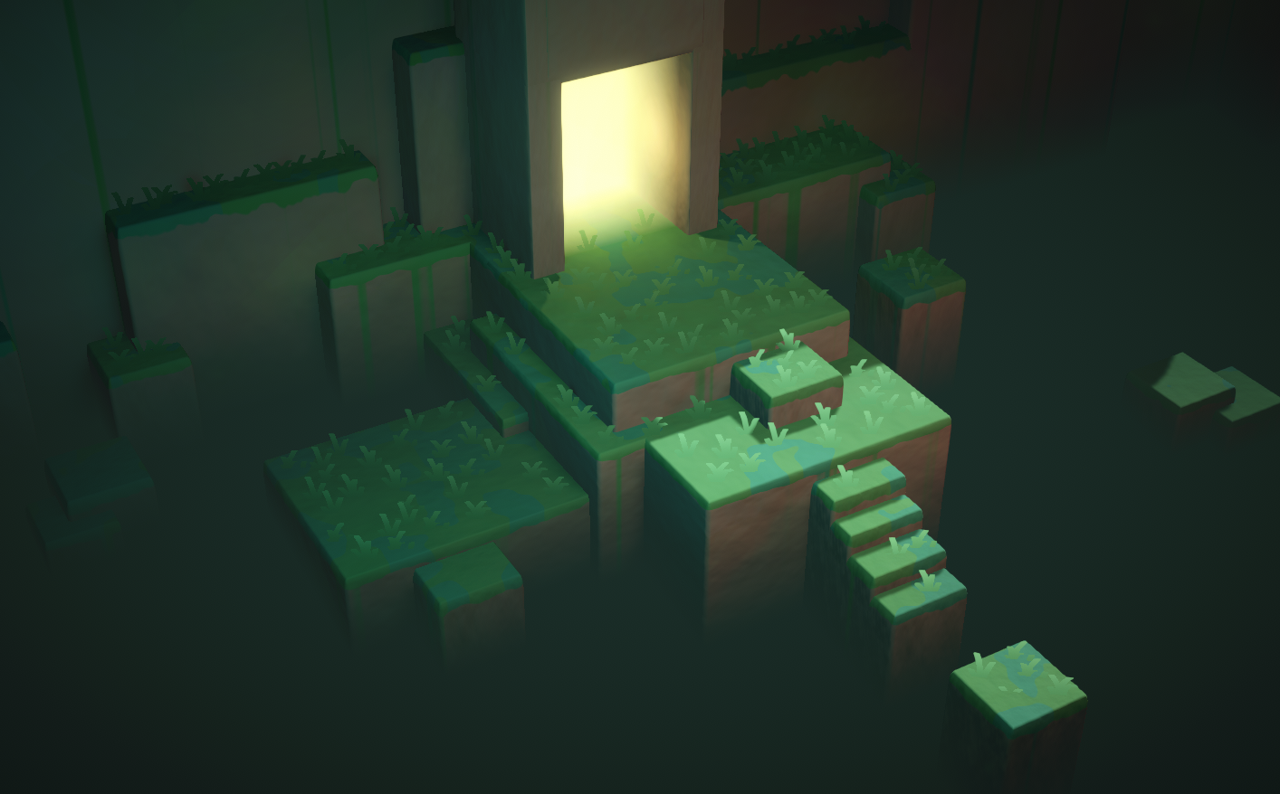
Two examples of vertical fog effects produced using the depth texture (scene depth)
yes
Thank you, I ll try that.
Hey, thank you! I don't know if you've ever dealt with that shader but I'm having a minor issue; the author gave the final graph for HDRP users (I use HDRP). Which looked a bit different than the URP one, I can't adjust the length/distance or whatever you call it. So it just goes like:

(I'm using it for making a corridor that fades into darkness)
wait.
You are the author.
Right ?
I've been trying to follow this tutorial but I really don't understand how this works https://www.youtube.com/watch?v=NiOGWZXBg4Y&t=303s

Let's learn how to make an awesome force field with Unity Shader Graph!
● Check out Skillshare! http://skl.sh/brackeys15
● Support us on Patreon: https://www.patreon.com/brackeys
● Project Files: https://github.com/Brackeys/Force-Field
● Water Shader shown in intro: https://youtu.be/jBmBb-je4Lg
● Setting up Lightweight: https://bit.ly/2W0AY...

So what I think is happening is that the scene depth will get the current pixel on the screen that's being drawn and the depth of it to the camera.
But I'm really confused about the screen position and what the w component is and why it can't just output a Vector2
What's the 4th value on the screen position? Is it depth or something?
Small tip that isn’t exactly relevant to screen position, if you hit F1 with any node selected you will open its documentation in browser
Anyways here are some answers.
Essentially Unity stores many different things in w depending on the situation. ComputeScreenPos is a little confusing at first (I still am familiarizing myself with all the coordinate spaces)
https://forum.unity.com/threads/what-is-screenpos-w.616003/
https://forum.unity.com/threads/w-component-of-in-screenpos.242314/

Unity Forum
I'm a noobie at shader programming and am trying to learn to create intersect highlight effect. but I can't understand some of the concepts and...
Unity Forum
I understand that the the function ComputeScreenPos takes in a clip space point and converts it to screen space.
For example, if my screen size is...
Oh thanks I looked at unity's documentation but I'll check out those forums and I also found thishttps://gamedev.stackexchange.com/questions/186226/understanding-screen-position-node-in-unity-shader-graph

Game Development Stack Exchange
I'm struggling to understand what exactly the Screen Position node outputs in Unity's Shader Graph.
I'm using the screen position with scene depth to calculate the distance between two objects.
Every
Another tip I would have is to open your CG Includes folder and whatever else (I’m away from my computer atm) and look through those files.
You can do this via file explorer but can find important files in the project window search.
I would look for anything within ShaderLibrary

GitHub
Unity Graphics - Including Scriptable Render Pipeline - Unity-Technologies/Graphics
So I can look at how the nodes work?
Yes. If you look at the documentation it’ll say what function any node is using more often than not. If you then look through your included files you can exactly what the contents of the functions are
You can find this via GitHub but looking in your local version of unity editor will ensure you are seeing what your project is using
Ok that sounds good thanks. I'll try that out if I don't understand something else but I think I understand how the intersection effect works now
I think that’s under GeometricTools.hlsl or something similarly named
oh ill check that out in the github
local file path would be /Unity/Hub/Editor/2020.3.8.0f1 (or whatever version)/Editor/Data/CGIncludes/
thanks I found it idk what a cginc file is though
it's a "cg include" file. CG and HLSL have similarities/share some things/I'm not really sure about the specifics of CG and HLSL but I know they are connected
https://docs.unity3d.com/Manual/SL-BuiltinIncludes.html
the other local file path you will want is Project/Library/PackageCache/Editor/Data/Nodes/Input
Common.hlsl can be found in a few different packages (like vfx and post processing) as well. All containing many different included helper functions relevant to each package (typically by Common.hlsl #include -ing many other files)
help
https://docs.unity.cn/Packages/com.unity.shadergraph@7.4/manual/Voronoi-Node.html
what exactly does raw cell data mean in this context ?
Hey guys, I've updated my Unity and suddenly my scenes' lighting got messed up: it's much brighter.
Any ideas? :\

howd i go about removing the voronoi cells close to the texture "borders" ?

and i mean entire cells, e.g resulting shape could be :

hope that makes sense.
Hey guys. I got a code in many languages (JS, C#, CPP).
I have converted it to GLSL, and it works, but I can't make it to work with CG Language.
It is a shader used to convert a Specular/Diffuse texture into an Albedo texture.
Could anyone give me a hand? I can buy you a coffee if you prefer 🙂
It has no compiler errors or whatsoever. Only the math seems to work differently in Unity.
80 lines of code, not a huge thing
Hello. I'm sorry if I'm asking this in the wrong area, as I am new to all of this..
My model has haircards and was made in Blender.
I want to use this model in Unity but I am having 2 issues.
-
I can't figure out the setup for texture maps... ( Albedo, Normal, Height, etc )
For the hair to look realistic like it does in Blender.
When using the Standard shader and the rendering mode Cutout, it either leaves too much "Alpha" or there is no more hair left. -
From the front of the hair, you can see through it. From the back, you can see the hair.. As if the texture is only on one side.
I really appreciate any sort of help.
If you need for information, just let me know. Thank you.
does any one know if you can render specific layers using scene color node
something similar to using 2 cameras for different layers and rendering one to a render texture
but as i am using a single camera can not figure this out
@mild lynxI don't know that you can, unless you do what you say and use multiple cameras. The scene-color node is a grabpass that runs between the opaque and transparent passes. So if you've composited opaque layers, it would get them all. IIUC. So your guess about multi-camera is a good one. Or you need to do whatever you're doing differently.
@grand joltHair is usually a special-function shader by itself. You'll need one of those. HDRP has one, and a hair master node for SG. For other piplelines, go shopping, or google is your friend. It is specialty stuff.
@echo kettle Do you have animated materials turned on in the editor?
@grand joltThat's the GLSL. What did you do for HLSL? Doesn't look too bad.
You might want a compute shader, or you can use a vert/frag (IDK what pipeline you're in either).
What do you mean you can't make it work? What happens?
Hi. It is supposed to return greyscale values with the SolveMetallic call. The GLSL call return the right values, the HLSL doesnt.
It takes the diffuse texture and a specular texture, then mix them to build an albedo texture
I could post the Unity version too (HLSL)
The SolveMetallic method on HLSL is returning mostly full black values with some overbright pixels
I have checked my inputs and made a 1:1 copy in HLSL
Anyone have a grabpass distortion shader that works on mobile?
anyone ? ive got no clue how to solve this
I may have messed up something here, I installed the shader graph package then the URP package and this is what I get as default
and I see no option to create a PBR shader

What render pipeline is compatible with unlit master?
both urp and hdrp I guess?
maybe I need to remove the packages and install them again
The PBR Graph option was renamed to Lit, and master nodes were replaced by this master stack in v10.
Make sure you have configured URP (or HDRP) properly in the project. Just installing it isn't enough, you need to assign the pipeline asset under the project settings.
You only need to install the URP package. All other dependencies are automatically included
well I can't seem to find the pipeline asset in the project settings
and no, its not the option

You need to create the asset first. The docs link above goes through the setup
oh there we go!
Hello there 👋 For my models I'm trying to add this glue residue from removed tape / stickers to add more detail, does anyone have an idea how I could achieve this material? Thanks in advance

I have cut rectangular planes to match the shape but I've been messing with different noise combinations to create a texture, with no results so far
For some reason legacy shader ain't working in unity urp..
Hey guys, say I have a sphere and I want to basically make the inside of the sphere completely white almost like a really intense white fog, how could I program this in a shader.
Is it not possible to read an array like this? https://hatebin.com/puazvbkjmz
I wanted to pass an array to the shader, then divide the current screen position by my tile size and then check the value in the corresponding array index to see whether to render the square or not. I'm doing something similar already but using a texture, do I have to do something different for arrays?
i'm just declaring it like float arrayName[10800]; in the shader
currently unity is telling me socket exception: terminating shader compiler process
Hello, does someone know why this is happening? It basically happens when i'm chaning the Vertex Position with a Position + Combine node.

I want to put back the visual part of the cylinder into the object itself
Recently my Shader Graphs have all been bugging out when trying to add new properties or change them in anyway. Giving me a NullReferenceException. They are still rendering fine but this is super annoying. Anyone know how to fix this?
NullReferenceException: Object reference not set to an instance of an object UnityEditor.ShaderGraph.Drawing.Inspector.PropertyDrawers.ShaderInputPropertyDrawer.UpdateEnableState () (at Library/PackageCache/com.unity.shadergraph@11.0.0/Editor/Drawing/Inspector/PropertyDrawers/ShaderInputPropertyDrawer.cs:142)
I've removed and reinstalled Universal RP to see if it would fix but no luck.
how do i change the reference of texture2d properties in shader graph
there's no dropdown showing up beside it for me
it's just nothing except the name

The property settings moved to the Graph Inspector window (Node Settings)
ah ok
thank you
You'll have to show your nodes for anyone to be able to help
Ah yes i've forgot to upload it

You probably don't want the world position there
how do i make a voronoi noise node sample its values from the centroid coordinates =
And how do i change it? I'm still very noob with it
There's a dropdown

what am i doing wrong

have you tried making _MainTex the name?
Also It needs to be exposed pretty sure
(the exposed checkbox)
i've tried both, it still shows the warning
i've also saved the asset
@meager pelican the converted version
GLSL:
https://gist.github.com/rickomax/95362b3355856378a1c78815497ebf4e
Unity (CG):
https://gist.github.com/rickomax/e9a0cf263dab9b669dd98fb7d73fbb61
Gist
GitHub Gist: instantly share code, notes, and snippets.
The code you're showing doesn't make much sense to me. diaelectricSepecular (a float3) is set to (.04, .04, .04) and then you mostly use the .x component except for maybe one call. Which IDK why anyone would code it that way, but to each their own I guess.
Whatever it is doing, you can trace it through step by step by outputting the colors, maybe scaled, and seeing what you get at each step with each version.
But my looking at the GLSL source won't help debug the HLSL converted shader, at any rate.
Oh, you edited. 😉 Hang on
It is used as a float3 when it is multiplied with the specular color, since every component must be multiplied
The GLSL version works fine (Running on Shader Factory)

The Unity version outputs black pixels only
The textures I'm using
The desired result (GLSL result is not the same, but is close enough)

The base code is taken from here:
https://github.com/KhronosGroup/glTF/tree/master/extensions/2.0/Khronos/KHR_materials_pbrSpecularGlossiness/examples

GitHub
glTF – Runtime 3D Asset Delivery. Contribute to KhronosGroup/glTF development by creating an account on GitHub.
Yeah, IDK off the top of my head.
The ThreeJS is using a multiplyScalar function call though, when calcing baseColorFromSpecular. But your input vector is .04 for all three components. So IDK.
Could be floating point issues too. Remember you're converting CPU to GPU. See
https://forums.developer.nvidia.com/t/floating-point-operations-difference-between-cpu-and-gpu/27334/3
But that's a SWAG.

NVIDIA Developer Forums
CPUs tend to do floating point calculations in 80-bit ‘extended’ mode and keep the results in this intermediate format. As such subsequent calculations are using the 80 bit value. On the GPU the single precision is 32 bit and double is 64 bit. As such doing lots of calculations on floating points you are likely to get small differences even i...
Try doubles maybe?
In CG?
you're writing an HLSL
Ah, you mean the inner floats
ok
I guess that if this is a precision issue, that should be happening in GLSL too
But I'm doing that
Like I said, SWAG.
(Silly guess)
Otherwise you'll have to step through both, step by step. And compare results.
Same result with doubles
Yes. It is just a pain in the a... from my experience (debugging shaders)
Tks anyway @meager pelican 🙂
@meager pelican there should be something wrong with my Unity inputs or the way I'm calling it.
I've tested both the HLSL and the GLSL shader in Shadered and they yield the same results

Maybe it has to do with the texture colorspace...idk
They're binded correctly, tho
I thought you were saying they yielded different results.
But I guess you're saying they yield different results from the CPU version.
@grand jolt
The Unity version yields different results
But it is the same code used in Shadered
Specifically the "baseColorFromSpecular" line is returning different values in Unity
Trying to figure out why
Have you checked texture import settings?
thinking color-space
And then there's this shadered thing...
Looks interesting
Shadered is fantastic. You can debug the shaders just like a C# file
You pick a vertex/pixel and step thru the execution
I'm creating my textures dinamically, but I've already tried creating them as linear textures with no luck
That's what I was saying above, that line looks different from the ThreeJS source too.
But if they're the same between Unity and SHADERed, IDK. I can't comment on SHADERed's stuff, haven't used it.
You could search your unity version for any shader compiler issues in it, or fixed in later versions. But that's another SWAG.
I'm not seeing it, as a 2nd pair of eyes.
You could try a native-software debugger and inspect it directly. But there's learning curve to that too. Another PITA, but you can also set breakpoints and inspect values. Both AMD and NVidia have them for download.
That's all if outputting color values for the various components doesn't help you. That's the easiest thing to do for shader debugging.
Yep, I could use RenderDoc as well, I guess, I have it here
But that is veeery strange, since, theorically, it should output the same bytecode as the HLSL from Shadered
Yeah, theoretically. 😉
It's supposed to be platform independent bytecode from the HLSL compiler, and then gets compiled by the platform, IIUC.
So IDK why the SHADERed compiler and unity's HLSL side would output different bytecode, since they should go through the ?same HLSL compiler? But maybe options?
Might be one for Unity Tech to handle/look at too.
I'm sorry but I can't tell much from here unless I really dug in and duplicated your setup.
There's also https://docs.unity3d.com/Manual/SL-DebuggingD3D11ShadersWithVS.html
Depends on what DX version you're doing, see comment at top.
Yep, I have to create a new project, since I'm not using it as a regular shader, but as a "image processing" shader
So it is harder to catch it with the debugger
@meager pelican anyway, if you want to take a look:
https://github.com/rickomax/ShaderTest

GitHub
Contribute to rickomax/ShaderTest development by creating an account on GitHub.
I'm curious now that I got this far.
But i have to upgrade to a later version of Unity. Be a bit.
It should upgrade...On unity 2020.3.something
How do I know what to compare it to though?
I have to install SHADERed?
Is that your test base?
Well, if you want to install Shadered, I can send you the Shadered project as well
Wait.
It loaded.
But I've tested it in some online editors like Shader Factory
I have two boxes, one is black, other textured.
Yep, the textured one has the optimal output result as a diffuse texture
The left one is using the shader to create such texture
Which isn't working ,as you can see
OK, that gives me a comparison.
But I can say the "baseColorFromSpecular" has wrong values, for sure
"baseColorFromDiffuse" too, it has some overbright pixels
baseColorFromDiffuse has this:

baseColorFromDiffuse from Shadered (left one is HLSL, right one is GLSL):

lol
baseColorFromSpecular:

baseColor

I appreciate a lot. I can buy you a coffee later for the help
I'm also working on it
You're getting zeros or nans, because of that black.
I've tried multiplying by 10,100,1000 and still black, and also abs() so not negative. So it's zeros or NANs
Division by zero !?
I'm getting this strange compilation warning too:
Shader warning in 'Custom/SpecularDiffuseToAlbedo': use of potentially uninitialized variable (solveMetallic) at /Repos/ShaderTest/ShaderTest/temp.hlsl(904) (on d3d11)
I'm not getting that warning, but that's a function name.
I think it's whatever the metallic function is returning that is producing weird results (so far).
Yep, that is what I guess
Do you know what values to expect?
But every place in the internet I search for this method, uses the same formula
Also, there isn't an explanation on how the formula works
If you have it return like .5 or something, you'll get a blown-out white cube
There is a live demo, tho:
https://kcoley.github.io/glTF/extensions/2.0/Khronos/KHR_materials_pbrSpecularGlossiness/examples/
glTF
glTF – Runtime 3D Asset Delivery
If you move the specular/diffuse sliders, the baseColor value is updated, that is the value I want
I'm checking function inputs. (Maybe we should DM this, might annoy everyone)
hhhmmmmm
AFK BBIAB (10 min)
Ty
Ok, if I remove the "sqrt" call from "solveMetallic", the result is getting better

The -b part is throwing the float range < 0
If at least I knew where they got this formula from
This is the shader I'm testing. I've based it in the PBRUtilities.cs from the glTF toolkit. It is slightly different from the one in the GitHub
Yeah, and it is weird since there's a constant 4.0 and a "looked up" .04..which you could just multiply out. The shader compiler will probably optimize that though. But you could end up with a negative value in there, which is undefined.
hmmm
Now I wonder if optimizations are messing up stuff
GOT IT WORKING
If I move both constants inside the methods (frag and solveMetallic), it works
Definitely optimization error

Working shader
Maybe this is a bug worth to report, not?
Result is not 100%, but is close enough (right one):

Yeah IDK, you could try. IDK if it is unity or MS or us.
Maybe when the constants are outside the function blocks, they get scrapped out by the optimizator
I mean, they may end up being used by one or another, but not both methods
The only thing I did was moving them inside the methods (had to copy it twice)
Oh, I moved the function call inline
And I substituted constants for that const float3(0.04,....)
It worked?
Meh
Better than before! 😉 Sec

But I think I still have an abs() in there and maybe f-ed up other stuff testing.
If yours is working, no reason for me to go dig to figure out what I may have done, or not.
Yep, moving the constants inside the methods worked
Not the most pratical solution
But since I'm running out of time with that...
Btw. I've PM u
I'll delete the sandbox project and ensure I don't have your code in my possession anymore.
Np, the code has nothing special
Hello. I can not use time node and do not know why? Sine and others work but not the time node.
I suspect it may be because Time is an ever-increasing value.
But sin would be a result between -1 and 1
So would cos()
And the others are frame time each frame (in fractions of a second).
@limber fossil
how can I restrict it between -1 and 1
because I need it to start from -1 to 1
and it should have started again
contuniously
Do you want it to cycle back and forth like sin() does?
Or when it reaches 1, go back to -1 again and then count up?
I think you mean the 2nd one.
when it reaches 1 go back to -1
OK, yeah.
The trick to that is to get it to cycle from 0 to 2.
And then subtract one.
And the way you do that is with the modulus operator.
So result = mod(time, 2) - 1.0;

The Book of Shaders
Gentle step-by-step guide through the abstract and complex universe of Fragment Shaders.
🙂
Hello, I have a problem with one step in my shader. I am basically creating texture for a throwing dices. I want to have customizable colors.

I have a texture for symbols, which are just white symbols (one color, various alpha on its borders) on transparent background. All works well untill I wanna combine the two together - I just want to take the background color (the yellow one in this example) and over it place the green colored symbols.
I cant manage how to do it, you see, the background turns into more orange-red as I increase the opacity in blend node and the symbols are yellow instead of green.
When I lower the opacity they are transparent - so only the yellow background is visible. Does anybody know what to do to make it work, pretty please? 🙂
Use the black/white texture result in the Opacity input, and two colours in the other inputs and set it to Overwrite mode. (Or an equivalent is using the Lerp node, with the texture in the T input and colours in A and B)
Oh, so I need to use blend, where Base is yellow, blend is green and opacity is a texture, which is black symbols on white background without anything transparent?
Does anyone here writes the shader with code instead of using shader graph?
If they're white symbols on transparent you can just use the A output in the Opacity instead. Sorry, I missed that part.
If you have a question it's better to just ask it
I tried that too, it doesnt work... 😦

Switch the mode to Overwrite instead of Overlay, and use the Symbol Color in the Blend input
Oooooooh, sorry!
I'm trying to control transparency of my material (which is a property of my shader) through a script, attached to that gameObject with my material
But is jsut doesn't work
Cyan, thank you very much! You saved me... I was stuck on that for hours. 😉
This is the part of pixel shader input, can someone tell me if it's wrong?
void frag(v2f i, out fixed4 col : SV_Target)
            {
                half2 uv = i.uv;
                col = tex2D(_MainTex, uv) * _Color;
                col.r = _Transparency;
}```Before instead of void I wrote: fixed4 frag (v2f i) : SV_Target
but it's not functioning
While in the script I used material.SetFloat to control the _Transparency
public Material hpMat;
float health = 50;
float maxHealth = 100;

    void Start()
    {
        hpMat.SetFloat("_Transparency", health / maxHealth);
    }

void Update()
    {
        if (Input.GetKeyDown(KeyCode.Space))
        {
            health -= 5f;
            hpMat.SetFloat("_Tranparency", health / maxHealth);
        }
    }
the health diminished by 5 each time I pressed space
And the _Transparency is 0.5 in view mode, so let's say it has been set in the Start as result of health / maxHealth
But in the game mode it remains 0.5 and cannot be changed
I would usually use the fixed4 frag (v2f i) : SV_Target method but that might still work too.
.r would correspond to the red colour channel, so won't affect transparency. You want .a instead. Though .r may still be useful to check the property is changing correctly. The Update in your C# code currently has the property misspelled (missing the s).
For a shader to actually be transparent, it should also be in the transparent queue Tags { "Queue"="Transparent" } and use an appropriate Blend mode. https://docs.unity3d.com/Manual/SL-Blend.html, e.g. Blend SrcAlpha OneMinusSrcAlpha in the ShaderLab section of the shader.
Man
I hate this
...
That misspelling!!!
Every single time I'm committing the same mistake!
Thank you so much!!
col.a doesn't work btw
The value of transparency in the inspector is going down
but in the game view it remains red
as I set it in the shader inspector

You could copy-paste the property name to avoid typos.
Also, it's better to convert it to an int to use in the SetFloat function if you're updating it each frame. That means you also only need to copy/type it once. e.g.
public Material hpMat;
float health = 50;
float maxHealth = 100;
int shaderProperty;

void Start(){
  shaderProperty = Shader.PropertyToID("_Transparency");
  hpMat.SetFloat(shaderProperty, health / maxHealth);
}

void Update() {
  if (Input.GetKeyDown(KeyCode.Space)) {
  health -= 5f;
  hpMat.SetFloat(shaderProperty, health / maxHealth);
}
I see, I didn't know this before. Thanks!
It should work if the shader has a Blend mode and in the transparent queue as I mentioned above.
lol I forgot to delete the // in front of my blend mode
Looks like it's working!
Thank you once again!
It doesn't work tho
Putting: fixed4 frag (v2f i) : SV_Target in place of: void frag(v2f i, out fixed4 col : SV_Target)
Did I forget any line of code, or it just doesn't work?
With the function declared as fixed4 frag (v2f i) : SV_Target, it needs to use fixed4 col = ... and return col; too. It's just a slightly different way of writing it, both end up being the same afaik.
Okay. I thought that writing void means that it can be changed and updated
While the other one can't
No, void just means it's a function that doesn't return a value. (same in C# and other languages too)
But why it needs a return col;
While the void one doesn't?
Oh
You just answered that
lol
Got it now!
@drifting lance This isn't the space to ask for free work.
How can I scale the UV? I need the UV to stay the same when I scale the object

Hey does anyone know how the performance would compare if you did all the lighting calculations and shading in a compute shader instead of in the usual graphics pipeline?
@loud remnant I'd suggest you google "unity world-space texture mapping" or "unity triplanar mapping" or some such, then come back with questions.
It would probably suck big time.
The thing is, all these "regular pipeline" things have been developed over time as "tricks" to avoid doing what you seem to be suggesting. That is because if you want to do what you say, you'd end up ray-tracing your entire scene. If I understand you correctly.
Even the fastest beefiest cards right now only do a limited about of that type of thing, like for reflections as an example. And then they use AI to fill in the blanks.
Now, if you want to go Hollywood style, get ya a render farm, and ray trace everything. Only a few minutes per frame, and you can have movie-like results.
😉
But otherwise, unless you can mathematically describe your whole scene, or you can make a lot of buffers (color, depth, normals, etc) and then ray-trace it all, it is hard to even approach at all, but even if you can, you'll be faster the standard way.
Compute shaders aren't faster than regular shaders, really, they just organize the processor cores differently.
You're talking about not only screen space shadows, but screen space lighting, and screen-space reflection, and ambient occlusion, or whatever you're talking about. There's a lot of stuff to it all.
I think we'll get there eventually. 10 or 20 years?
ok thank you!
Hey , want some quick info from you guys.
Is there some limitation with Render Textures and their formats in ios?
Do Render Texture behave differently on ios devices?
This is what I have in my Editor
https://imgur.com/a/TThfDLu
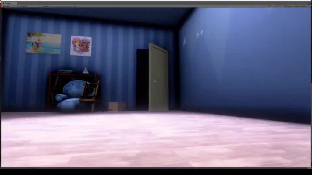
This is what comes in an iphone X (just talking about the shader working on the characters, it uses the depth to calculate those white outlines and renders them together to a RT that is pasted on a Quad infront of the camera)

SVT for URP - any estimations?
Is there a reason why you are using a render texture for this effect? It looks like a simple fresnel outline to me.
Are you using multiple render target?
I'm not sure is mrt is supported on iOS
This one is not using the fresnel effect.
So I am not the one who made this shader. I don't have the knowledge to code shaders yet.
My friend did this but he had also made one with the fresnel effect and that did not look as good as this one. (This one uses the depth to create this occlusion type of effect)
Is this look achievable purely with the fresnel effect?
Yeah 2 cameras render to textures. And yes it does seem like one of them is not working correctly
@wintry ridge The effect just looks like standard fresnel to me. I don't see what depth could be doing in this effect. What occlusion type of effect are you talking about?
Avoid doing fullscreen effects on mobile if you can
not necessary fresnel, looks like a simple rim lighting with some transparency could do the trick
And how would you do rim lighting without fresnel?
@tacit parcel Yes, that's fresnel. The dot product of the surface normal and the view direction.
Let me show the standard fresnel that we did
Photo from Nakul🎮

Did not look as good as that one. I am sure it can look good.
All because I can't fiddle around with the shader code and my friend does not have time to do a lot either.
Do you like the low poly look of the other effect?
Can anyone here help me with this effect? I'd love to hire someone to enhance the visual effects of my memory snippets.
I liked the glass effect, felt more like a memory that the above one
Anyone knows why activating emission but settings it to 000 (to animate it later) on the URP standard lit shader turns it off on compile?
Hello there, someone knows the equivalent of that Shadergraph node in Amplify Shaders please? 🙂

I need the position of the gameobject... :/
I haven't used ASE, but the position is equal to UNITY_MATRIX_M._m03_m13_m23 (3 of the components from the Model Matrix). Alternatively, transforming (0,0,0) from Object space to World space should give you the same position.
oh of course!
I should have though of that damned
as always you are the best @regal stag
Should be that then

without having to give any vector in
thanks again
Yeah that should be right
@pale tapir Though something to bear in mind is that if the object is dynamically / statically batched it'll combine meshes and it'll change the origin. This'll only work for non-batched (or srp-batched) objects.
https://gamedev.stackexchange.com/questions/151904/how-can-i-roll-up-a-plane-with-a-vertex-shader#
I'm trying my best to convert this to shader graph to use in URP
Game Development Stack Exchange
I have plane that I want to roll up using a vertex shader, like this:
I found a math demo that shows the kind of curve I want my mesh to follow. I tried implementing this in my shader code, but the
I tried my hardest to convert the shader code logic as it was written into nodes

but i'm having no success in getting it to work on a hi-poly ribbon mesh
It's a big ask but if anyone has the time to take a look at my graph ....maybe you can see what I'm doing wrong?
long shot but it'd be massively appreciated ❤️
@wintry ridge I'd check the shader for half/float problems. What happens fairly often is that when you run on a desktop, all half values are done as full-sized floats due to the 'bigger' card. They don't even bother with half-precision. But in mobile, they use half to save on processing (heat/battery/bus-speed). So when you move to mobile calculations that worked on desktop don't work on mobile the same way.
I'm totally guessing here.
Check precision in the shader.
But since you didn't post the shader, IDK if this even makes sense or not. I'm surprised at the pattern and transparency.
@tight forgeJust my 2-cents, but if I were you I'd seriously consider making a custom-function node and putting all that math in that, with appropriate inputs and outputs to the vertex position. And maybe upgrading SG to one that has the vert/frag stack.
The example shader in your link is mostly a custom vertex function in a standard Surface Shader. If I read you properly.
Hey guys. Any idea why Unity calls every shader pass twice?
I can certainly give the custom func node a try, i hadn't thought of that! thanks @meager pelican i'll give it a go
This is related to both custom and built-in shaders.
Details of this issue: https://forum.unity.com/threads/shader-pass-called-twice.1112719/
Unity Forum
I have a world-space UI canvas which is rendered into a render texture.
For some reason every shader pass of each mesh is called twice.
[ATTACH]...
I'm trying to solve an issue in my grass system. TLDR: I'm spawning dense fields of grass across large terrain-like mesh objects and combining the field of blades into one game object and what I'd like to do is be able to start with a grassy terrain and place buildings, rocks, trees and other details after spawning the grass but allow those details to displace the blades so they are compressed and not poking through geometry. Is there a feasible solution for this?
Deleting blades by hand has become untenable. I've tried using a custom renderer with mask shader to hide the blades. It works okay but it ends up masking the grass that should appear in front of objects too and it should only remove or hide the blades that are poking through geometry. I've also been trying a render texture solution where a top down ortho camera grabs mask objects on a hidden layer and feeds them back to the grass, but have been unable to translate the positions correctly back to the shader.
You could try calculating the worldspace position of the grass blade's x/z plane (no height) and then checking the depth buffer to see if that worldspace position varies from something. Like draw all the rocks/trees first, not even terrain, and then you can tell if you have any "objects" there, then draw terrain, then grass.
Guessing.
Would work all long the height since you can ignore height.
IDK why you want to draw grass first, you can't really "take that back" and displace it later after it is drawn.
Yeah it makes for a difficult problem. The reason we're doing it this way is so we can compose and visualize large areas of the game world and we want to be able to have the option to change the locations of buildings and trees and so on without having to rebuild the grass mesh each time we move something.
You won't need to rebuild the grass mesh if you displace the blades in the shader.
Trying to find a way to do this that is non destructive. The grass fields are spawned and combined into one large mesh obejct after blades are placed to avoid performance issues or having hundreds of blade object.
Do you want to prevent grass from appearing to clip into objects or do you want to prevent seeing grass from outside clip inside interiors?
To rephrase, would you be okay with a solution that only hides the part of the grass that has clipped inside, rather than hiding the whole blade of grass if part of it clips?

You mention trees, though. I'm thinking more about building interiors.
This image summarizes my problem pretty well, you can see the grass appearing to stab up through the tree trunk and rocks
The solution I'm thinking of wouldn't fix this example
Is this grass just quads with grass texture on it or is each blade modeled?
The grass is one combined mesh composed of quads mapped directly to the terrain mesh it sits above. The quads are spawned at each vertex on the terrain and offset slightly randomly to look more natural. Then the quad is UV mapped to 1 of 4 grass blade textures randomly to look more natural as well.
I don't think there's any shader trick you can use to fix this problem. There just isn't any way to determine if something is inside other geometry vs just behind it.
So I think the solution would be via script
Yeah...hmmm
maybe if you had a top down texture of the terrain marking where objects are on the terrain, you could sample this in the grass shader to determine whether it's inside an object
I think that's what you meant by the mask shader approach
Yeah exactly
I was trying something like this but the render texture wasn't properly capturing the view. I could only get my "grass benders" to stay positioned properly when my game was using a 1:1 ratio camera
You're not using Unity Terrain, right?
No it's just a subdivided plane made in probuilder and distressed
These images might not be useful at all to you but here's where I'm at with the render texture in a test enviro. The blue circles should stay positioned to the player as well as the tree trunks. The black area represents grass that would be uncompressed and blue would be fully compressed. Could soften the effect around edges later. In 1:1 display it's working.

But here you can see that in 16:9 the render texture doesn't map properly. It seems a render texture camera always captures the image in a square format.

Why is the view isometric rather than top down?
How many of these circles do you think you'll need?
I'm mapping the render texture using the screen position

the circles are captured from sphere meshes that are on a hidden layer that only the render texture camera is grabbing
so for a house it may be a blue rectangle, but the idea would be that the blue areas would be read by the shader to do the displacement
I'm only asking because if it's a reasonable number, you could just pass in an array of sphere positions into the grass shader and have it loop through it
that was my thought too but they will be different sizes based on the objects and if there are a lot of rocks and trees on screen that would be a lot of stuff to loop through rather than reading from a single RT once
You need to map the base of the grass to the xz position of the mask.
Right that's the solution I've seen although following a few different tutorials that all use the same method did not seem to work in my case. This is the conversion I have found but it does not seem to be showing in the shader.

Subtract camera position from world position, multiply by orthographic camera size and offset by 0.5, 0.5 to get center of UV
It doesn't make sense to use the Screen Position in any of this though
Are these two separate solutions or are you using both at the same time?
They are separate, the second one is the correct one from what I've read, that should be fed into the UV of the RT
but I'm getting no results from that, the screen position doesn't make sense but has been much closer to displaying what I want
Have you tried outputting some of those values in the shader to see what they are?
Like outputting UV directly as color instead of using it to sample the mask texture
Is it all black? All white? Something else?
I haven't but that's an interesting idea, so just output the end of that graph to a color?
Yes

This part seems to be the 0,0

It looks "backwards" too, black should be lower left normally, yellow upper right. But I haven't figured out their shader yet.
That's not flipped rendering.
Hang on my values for ortho size and cam position are not reading here
Hmm I just manually put the orthographic size and position into the graph and the results look the same
IDK if it depends on what direction you're facing or not. Those are offsets I suppose.
Is your main camera ortho or perspective?
Main cam is ortho
None of this math makes any sense to me and I wrote smth like this in HLSL 😄
So you're drawing this "map" for a really large area all the way to the far plane? And trying to map worldspace gras location to it.
Hey Beat. 🙂
Does this look more correct?

Yes, but I'm guessing. I don't understand your shader yet.

Hello, anyone with more knowledge on shader graphs, can anyone tell me why the texture scales like this?
trying to make a tree material that works with hdrp but im trying to scale it so it fits better, rn it looks like this

hi
umm i need help if u can please?
- Library\PackageCache\com.unity.xr.management@4.0.5\Editor\XRGeneralBuildProcessor.cs(83,52): error CS0117: 'BuildPipeline' does not contain a definition for 'GetBuildTargetName'
idk what to do to this thing and i cant rename anything its just wont let me
@stable lake maybe the texture is set to clamp in texture settings? Is that a thing?
umm help?
yeah that does it, thanks
;-;
@verbal python you need to use at least Unity 2019.4 to import that package.
Anyway, pretty sure you can also override the sampler on shader level.
@willow pike They're using grass polygons, and offseting them based on a lookup texture that represents bend forces. Right?
But that's not exactly what you want. You want to clip your grass, and IDK if you have individual polygons for grass (I was unclear on that).
ey
Wrong chat btw, Malusic.
another thing, does anyone know how to create a material for leaves in shader graph? i tried the texture to alpha node, then made it transparent, but doesn't quite behave like it should.

Alpha transparency for vegetation is crazy expensive.
Just use alpha clipping.
You probably didn't tick Alpha is transparency in texture import settings.
@grand jolt wish channel can i get help with?
Or maybe you forgot to split the base color vector and connect the alpha channel with the Alpha on the master node.
Yeah their shader is displacing grass using an ortho top down RT camera capturing a hidden layer that contains wind and the grass is reading that info in world space. My idea was to do the same thing to displace grass under trees, buildings, rocks, etc to prevent clipping.
😐
#archived-code-general maybe.
umm k
@stable lake I answered a bit higher 👀
yeah man i am trying to get it working but this shader graph thing is basically chinese to me, but your answer is really helpful

just not sure why my alpha clip threshold is greyed out

Cause you didn't enable alpha clipping in master node inspector.
ah
I think you should just discard the whole blade if it is sitting on an objection that would make it not-grow. But if you're on tile-based mobile, it's rough, but may be your only option. IDK that setting it 100% transparent is much better, but you can try that instead.
You can do fast culling by emitting a Nan, Nan, Nan vector as vertex position 👀
Courtesy of Far Cry V terrain.
In mobile, without crashing them? Cool.
Only on PC and all consoles 😢