#archived-shaders
1 messages · Page 195 of 1
Hmm this is bad, i need surface shaders
Probatly gonna stick to the old "built in" render engine then
Or maybe there is a way to do it in urp, anyways thanks @regal stag
This is very helpful, thank you for the detailed response!
I'll give the blit render feature a shot and see if I have questions pertaining to its use.
Is there a reference for what urp features are and aren't supported by different platforms?
Particularly what webgl supports?
Hey,
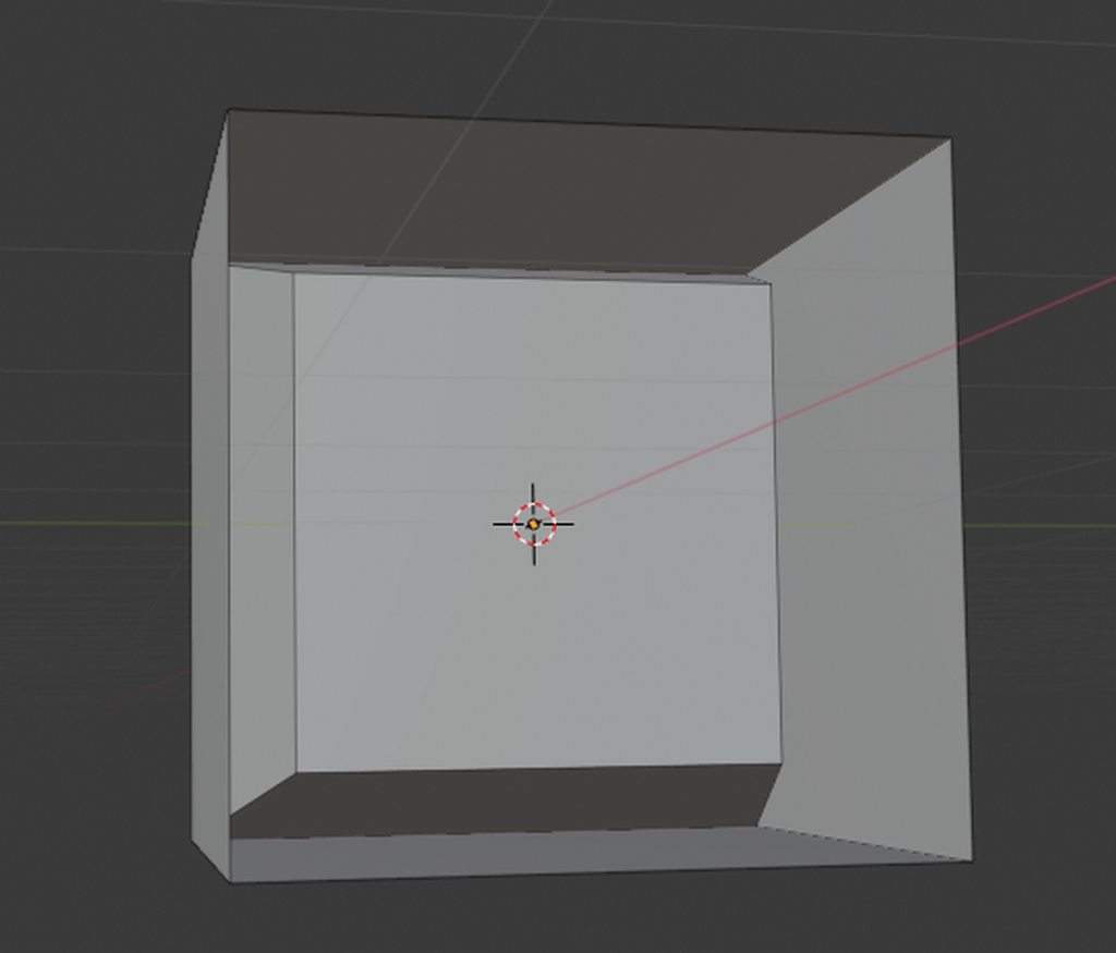
I'm having issues with a very basic shader, but can't seem to find anything how to solve it. I created a cube in blender, that has some inset faces and one side is "open" so you can look inside it (first image in imgur). I exported that into unity and gave it a material with my shader.
Now what I want: I want my object to look like it does in blender: You can look into it from one side and see the inwards facing faces.
I thought about it and came across culling. But Cull Off still had some problems, it rendered some faces behind others should be ordered the other way around. Then I changed it up to two render parts one with Cull Back and one with Cull Front, but that still has issues (see other images in imgur), it seems to show the inset part correctly but on the other hand you can look into the cube from every side and not only the one thats "open".
What do I have to do to achieve the same look like in blender (e.g. the natural way)
https://imgur.com/a/5f0CrCh
https://gist.github.com/staddle/0a4cc170126bf46d959faa21c8b75fa5

so since an array within a struct within a list in C# is not blittable, is an array within a list blittable? to send to a compute shader, because I REALLY dont wanna have to loop unroll 512 times in the shader(octree traversal and primitive drawing for each octree leaf node)
@errant turtle it looks mostly the same, is it just that you can't see the sides anymore when looking around... your texture needs to be set to two sided, or your geometry needs faces pointing both directions
It looks almost right, just that I can see the inset part of the cube even on the sides that aren't open (see image 3) and some drawing issues where some back faces are drawn above the front facing oens.
Is it not possible to do this without creating new faces pointing in the other direction? I need to have this kind of shader on a model created by MRT scans so its not really possible to make new faces...

Im not working in shadergraph, do you know what option it is in CG?
I'm not farmiliar with CG shader programming, havent played with it yet, but maybe this direction? https://en.wikibooks.org/wiki/Cg_Programming/Unity/Two-Sided_Surfaces
This tutorial covers two-sided per-vertex lighting.
It's part of a series of tutorials about basic lighting in Unity. In this tutorial, we extend Section “Specular Highlights” to render two-sided surfaces. If you haven't read Section “Specular Highlights”, this would be a very good time to read it.
sounds promising, im gonna take a look! Thank you for your help!
np
Sta treba da se uci iz francuskog
@primal imp Keep it in English, please.
does anyone know if there's a way to make the shader movement interact with the physical world? for example - like i can use the particle system to make a collider out of every particle. I made a beautiful water shader and i'm trying to make it interact with a boat that is floating on top (rise and fall with the waves) and i can't seem to make it work. i ended up making a C# code to make a plane simulate water using noise. it looks ok, nothing amazing.. and i wasn't able to make it look as good using a shader, however, it does interact with the boat (if in a less than satisfactory way). using my water shader with the water plane created very poor results. any ideas would be welcome
Hey guys! I don't know if this is a common problem, but I'm trying to figure out a way to prevent two transparent objects from overlapping, and instead appearing to combine into a single transparent surface. If anyone has any recommendations or solutions (preferably using Shadergraph), please let me know! This included image might serve as a better example of what I am referring to

Maybe look up stencil pass, but IDK if you have to hand-code that with SG or not. There's a few approaches, one might be to not-draw if you've already drawn, and you can tell that by the stencil value.
Another idea is to use an off-screen buffer/render-texture and draw into it, and then smart-blit over top of your scene and blend with transparency during that blit instead of in the off-screen buffer. So the off-screen buffer would be opaque.
Just 2c
You can do the off-screen thing with camera stacking and layers.
I'm trying to do some screen space distortion, but I confess I'm not so great with this. Is there something obviously wrong with how I've setup this shader graph? _MainTex is camera color

It has pretty much the desired effect, except everything is tinted green...
I'm certain it's the final node before it turns into the Fragment Base, Add, because if I pull each of the other parts in separately, it doesn't turn green
Another question is anyone knows. Using shader graph, how would I go about enabling/disabling specular highlights?
If you're in URP & using the PBR/Lit Graph, the keyword for toggling it would be _SPECULARHIGHLIGHTS_OFF. Boolean keywords need to end in "_ON" however in order to allow them to be exposed though, but that would change the keyword. :
Can set it through C# or a Custom ShaderGUI, or using the debug inspector on the material though.
Ideally you'd find a way to combine the UVs so you only need to deal with a single texture sample. It's turning green as the "black" parts of your UVs are (0,0) which corresponds to the pixel in the lower left of the screen.

@twilit cargo you can render the objects to a render texture and then render that texture to a transparent quad
Is there a way to feather an ellipse, like Photoshop?

Hello, I finished my avatar using blender and the only thing left is the shader, now I using unity and Ive got the .shader file but I do not know how to add it
This is what I would do (the maximum is just making sure the border is not 0, as that is a division by 0)

Oh and you should saturate the output
That's wicked, I'll give that a try. Thanks vertx
Also, depending on what look you want, a smoothstep may be better

Absolutely incredible, can't wait to see what kinds of results I get with this
If you are ever looking for shapes, looking to SDFs is the way https://www.iquilezles.org/www/articles/distfunctions2d/distfunctions2d.htm
which is practically just "distance to the surface"
you can use that distance to produce the edge fading however you want
This is really neat, I'll play with it. Some of it is a bit over my head... I don't really understand what removing the blue and alpha channels from the UV does
They're extra channels that we're not using, annoyingly shadergraph doesn't neatly provide just uv
Ahh, good to know
I suspect this will have worse performance than simply sampling a texture2d, but I have procedural needs for this so it's worth it for me
I'm unsure, but this is also scalable in resolution
Yup, that's excellent.
shaders need materials to function, you can right click on the shader and click create > material and that'll create one that uses your shader.
But generally external models do not have custom shaders, so I'm not exactly sure if what you're talking about is a Unity shader 😛
@vocal narwhal Any idea why I might be getting a different subtraction result when compared to working with ellipses?

oh right, you did mention that
though, yes the result will probably be different, but it's simple maths 😛
That made all the difference, thank you!
thank you so muchhhh
@thick fulcrum the foam shader doesn't work with cel shading, like the foam bits still appear in the water, but it doesn't border around objects that intersect the water
do you know a possible solution by any chance?
without more details I've no idea, in what form is the cel shading and how does it interact / impact on the water shader?
I'm unsure, I'm trying to recreate it, but for now I just copied one online as a placeholder

Hi guys, in this video I'm walking you through creating your own cell shader from scratch. Its very easy and perfect for beginners. It will show you the basic structure of a fragment shader and walk you through the math involved in calculating the light and shadow areas in a toon shaded object.
If you enjoyed consider subscribing - https://www...
this one
{
    Properties
    {
        _MainTex("Texture", 2D) = "white" {}
        _Brightness("Brightness", Range(0,1)) = 0.3
        _Strength("Strength", Range(0,1)) = 0.5
        _Color("Color", COLOR) = (1,1,1,1)
        _Detail("Detail", Range(0,1)) = 0.3
    }
        SubShader
        {
            Tags { "RenderType" = "Opaque" }
            LOD 100

            Pass
            {
                CGPROGRAM
                #pragma vertex vert
                #pragma fragment frag

                #include "UnityCG.cginc"

                struct appdata
                {
                    float4 vertex : POSITION;
                    float2 uv : TEXCOORD0;
                    float3 normal : NORMAL;
                };

                struct v2f
                {
                    float2 uv : TEXCOORD0;
                    float4 vertex : SV_POSITION;
                    half3 worldNormal: NORMAL;
};``` float4 _MainTex_ST;
float _Brightness;
float _Strength;
float4 _Color;
float _Detail;
float Cel(float3 normal, float3 lightDir) {
float NdotL = max(0.0,dot(normalize(normal), normalize(lightDir)));
return floor(NdotL / _Detail);
}
v2f vert(appdata v)
{
v2f o;
o.vertex = UnityObjectToClipPos(v.vertex);
o.uv = TRANSFORM_TEX(v.uv, _MainTex);
o.worldNormal = UnityObjectToWorldNormal(v.normal);
return o;
}
fixed4 frag(v2f i) : SV_Target
{
// sample the texture
fixed4 col = tex2D(_MainTex, i.uv);
col *= Cel(i.worldNormal, _WorldSpaceLightPos0.xyz) * _Strength * _Color + _Brightness;
return col;
}
ENDCG
}
}
}```here's the script for reference
i really have no idea how to recreate it in shadergraph, but i'm trying lol
well simply put having glanced at the code it's opaque, not transparent which will mean depth node in the water shader cannot see the terrain.
Generally speaking I'd advise sticking to shader graph unless you are absolutely prefer code, Cyan's lighting stuff is spot on for shader graph and you can replicate toon shader easily enough making it into sub graphs you can just add into your water shader.
The only thing you probably would need to change in that instance is lit graph to unlit master node and or work from one of Cyan's templates.
i prefer shader graph, i just really liked the look of this particular toon shader
thats why im trying to recreate it in shader graph
and yeah having it as a subgraph would be super handy
thats way i could just apply it to the polybrush materials, for example
did you look at Cyan's lighting example I linked the otherday?
I'm pretty sure his toon example of the lighting is almost identical to that code above (but not looked in a while, so could be wrong)
is there any extra assets i need to recreate cyan's shader?
it looks like it might be missing some things

don't think so, the github link should have everything if you clone the whole thing
looks like it's missing the subgraphs in that screenshot / custom code links, they might just need re_allocating assuming you downloaded everything and are not using a bugged unity editor version 😛
i see
btw, am i able to use textures along with the cel shader?
wait i could probably just do that myself nvm
one you have the lighting, you can work just about anything you desire from it. Textures np, normal maps for extra details etc all doable
also the previous cel shader allowed you to adjust the level of "detail", which was basically how many shadow lines there were
so like you could have 5 shadow lines that progressively got darker
or you could have just one shadow line
ect
am i able to do that here? if not, how could I achieve an effect like that?
Cyan to the rescue 😄
Mine uses a ramp texture to control that, but that could also be swapped out
ah i see, thanks
so i could just make an exposed texture, then make like 3 ramp textures, each for varying levels of shadow, then swap that out in the material editor?
Yeah, I think I have 2 ramp textures as examples. I think 50% of it should stay black if you are also receiving shadows or it won't look as good
Well thanks for everything Cyan! Sorry about being so stupid about literally everything, but it's nice having a toon shader in shadergraph to mess around with now
btw, what is the "shadow reciever" shadergraph for? is that necessary for the toon shader? or is it something else?
It's just a different example of usage of the custom lighting functions. It's not related to the toon one
whats going on with this @regal stag ?

nvm figured it out, sorry for the ping
btw is there a way to decrease the alpha of the shadows?
that way i can toggle the shadow "strength"
Might be able to change the shadow strength on the light itself. I can't remember if that works with the graph or not though, the combination with the ramp texture might have messed with that
Oh or maybe I use a Step on the ShadowAtten output
ok i dont think i understand how to put the shadows on a texture

lmao
wait i got it
i needed a multiply
btw for some reason theres a purple dot on the light side of the sphere, do you know the reason why?

i checked and it wasnt bc of the texture
@regal stag
i got it working for the most part, i still gotta find out why that purple spot is there on the light side of the sphere though
@thick fulcrum is there a way to offset the shadow texture? if i do that I might be able to make it so that the shadow type can be fully customised rather than having 3 presets
It might be the ramp texture trying to repeat. Make sure on the texture import settings you set it to Clamp
texture import settings?
The settings in the inspector when you click on the texture, inside unity not shader graph that is
You could also override it in the graph with the Sampler (SS) input on the Sample Texture 2D nodes.
that fixed it, thanks!
Do you guys know if theres a way that i could just have a texture be the foam border of objects, and have it be wrapped around anything that intersects the water plane?
not sure I follow, but in theory with the foam setup it should work on anything which goes into the water that writes to depth (so not transparent materials) but any opaque objects by default will work.
You'd likely have to generate the mesh or model it manually with appropriate UVs for something like that.
or yea what Cyan says, the cleaner method using depth would be to have a second camera capturing that from an overhead perspective... but that gets messy if your not experienced 😛
damn
@lethal brook water is a luv hate thing for me, I went quite far down the DIY route while always keeping an eye on Crest. I seemed overkill for my project at the time but now I have grabbed Crest and I'm so happy I don't have to mess around with water anymore 😆 they are always improving it, while it's not yet got shader graph integration for easier customization (due to missing Unity features) it is possible to create a toon / stylized look.
crest?
it's on asset store, URP and HDRP versions... the version for built in render is on Github and fully usable for free. But if you going URP it's a small fee for what you get imo
I believe it's mobile compatible too but it's pretty quick for all that it does
what does it do?
quite a list of features, some of the main selling points are water interaction (wake from boats) whirlpools that sort of thing. Dynamic wave placement, even some spline wave for doing shore effects the list goes on
if you look on their discord it's probably easier, Critter Crove is one that springs to mind which is doing stylized water
it all depends on ones end needs and goals, as well as target platforms as to what is best for a given project though. so never take my word on it being ideal for your situation, but it's well worth a look 😉
How can i make something like this in the built-in pipleline? Its fairly simple with shader graph but i dont have access to that 😭
(the black door)

i see
Hey, I'm super new to shaders and wanted to make a simple outline to "highlight" clickable sprites.
Tried to follow few tutorials but everytime I get something else than what they are showing.
Adding shifter alpha difference to main texture additionally subtracts other side which doesn't happen in tuts.
Anyone has any idea what might be causing it?

I might be missing what youre trying to do, but you gotta do it in 4 directions and add all those together
The right side of the texture is 0 (black) subtract 1 (white) which is leading to negative values. You could use a Saturate node after the subtract to clamp it between 0 and 1.
that reminds me, how do you go about making an outline shader in shadergraph?
i want all living entities in my game to have white outlines, as well as interactable objects when you're near them
Search outline shader unity in youtube, lots of options and tutorials
yup, apparently adding other side outlines fixed this issue, now the problem I have is that my sprites are black for no reason 😄
I think it's because I've chosen Lit version... Can I change somehow it to Unlit or do I have to recreate whole shader in Unlit?
Yeah, you can add an Unlit Sprite Master node to the graph, right-click it and set it as the active one.
thank you!
I control my sprite's color usign Sprite Renderer's Color property.
Sadly this color is also applied to my newly created outline.
Can I somehow prevent it from coloring it?
(In the screenshot all three curved lines and bottom half-circle have a white outline)

I dont know much in unity, but does anybody have any clue of that issue here?
Look at the vehicle's turret, its material has some issue which i cant find. I have set all the model's materials to use the exact same shader settings.
Any help is welcome. This light-line on top of the turret is wrong. It should be there
Is there a way to add intelisense while coding shaders?
hey there
in urp how can i make my background of the shader laser to be transparent and make my laser to be without black transparaent background?
I notice that in some shaders I am converting for use in URP that CGPROGRAM, ENDCG is being used instead of HLSLPROGRAM, ENDHLSL
They compile fine but was wondering if there is any advantage to using CGPROGRAM syntax instead?
CGPROGRAM includes some additional files which will cause redefinition errors if you try to include the URP ShaderLibrary Core.hlsl in the shader.
So for my water, I'd like to have 3 variations of water on the same plan, each with a different colour
So for example, water close to the island will be shallow and have a lighter colour, meaning the player can swim through it
Water farther from the island will be deep and have a darker colour, meaning the player can dive in it
Water farthest from the island will be impassable and very dark, meaning the player can't swim through it
I would use polybrush but i need the water shader
just remember, its all numbers, figure out where your getting the difference in numbers from and feed it into the shader to control an appropriate variable
i've tried copying the polybrush shaders into the water shader and tweaking them, but it didnt work
so im kinda stumped on how to do this
start from the base... what numbers do have that designate what water is what... is there a way you can measure the depth, are you feeding it from a texture. think in numbers not visuals
@lethal brook You could use polybrush to paint the vertex colours of the mesh. Obtain it in the shader through the Vertex Color node, or COLOR semantic in the vertex input struct in shader code.
this is shadergraph... its a visual shader editor...
it is visual but the shaders ultimately run on numbers in the background... either positions, uv's texture values... its all numbers
I'm aware but i don't see how exactly that helps when making shaders in shader graph
which does not rely on numbers in order to be utilised
i don't mean to come off as rude i just thought that was funny
thanks @regal stag
it helps because if you can have a number you can reference that shows the depth of the water, or the distance from land you can use that in the shader to designate the color output. understanding what numbers you have to work with and how to generate the number you need, makes it much easier to figure out what your shader needs.
all shader functions are just passing or manipulating numbers, or groups of numbers. like a texture has 4 numbers stored in each pixel, R G B and A. you can pass any data into the shader with that encoding whatever you want into each channel, then splitting out that data once inside the shader and graphics cards are built to be super efficient handling data in a texture. that fact that its a visual texture may no relation to the data encoded in each channel and what you do with it.
like an ORM texture, its encoding other information that's not directly visual but is used by the shader to manipulate how it renders.
What you're basically saying is "if you want to run faster, think about the atoms in your legs"
no I'm saying if you want to designate some water as being deeper, then think about how you are going to tell the shader which water is deep
gonna get into making shaders in unity. should i be starting with shader graph or just writing them from code? i have a lot of coding experience and a small bit of experience writing shaders in HLSL/GLSL already, but i hear shader graph is really good.
Anyone?
@cold ermine best way to start with shadergraph is just to start playing with it, the normal hello world kind of thing us usually just throwing a noise function onto a model. And playing with how you can change the mapping around. It compiles down into code after your done it just makes it easier to see and hookup data flow. As a bonus you can see the shadercode it compiles into after your done to cross compare what code you expected.
“Add a node” and just start looking through all the different nodes and whatnot you can do. Know that whatevet code or node structure you end up with runs on EVERY pixel that renders, so whatever math you are doing only affects a single pixel, its like a recursive problem on some level, but you can feed in several world feedbacks, like the actual world position a pixel is at, or where it is in local space of the object, or the uv coordinate on its texturemap. Or even down to the screen position. Almost every data input can be fed in from c# code by making it a property and using the renderer.setfloat() code theres one for almost all the stuff. (Only exceptions is you cant pass in gradient data directly)
I know how to use SG but you can't use it in the built in pipeline thats the problem
Its easy in SG just a time node feeding into some sample noise and done :(
Depending on how extensive your project is. You can start a new one under, URP or if its fairly far along you can download URP from asset store and use that which supports shadergraph
Oh derp... i read your and Christophers post as the same, my original comment was aimed at his question... sorry 😦
Just wondering, in Shader Graph is it more expensive performance-wise to have multiple Position/Normal Vector etc input nodes in the same graph, vs a single node with lots of wires connected to it?
Obviously the latter potentially makes the graph a lot messier if the position/normal inputs are needed multiple times
that might change soon
@half remnant maybe something with the script that is setting the material properties? it only breaks after you click that generate button... err nevermind wait i didn't watch the second video
@half remnant looks like something else in your shader is still set to origin in worldspace for some reason. it would be helpful if you can share the shadergraph
@half remnant what happens if you change position node to worldspace?
ah ok so vid 1 is object, vid 2 is world
@half remnant ok then i'm back to being more suspect about whatever that planet generator script is doing... or maybe just something isn't executing when you expect
@half remnant try enabling "always refresh" in your scene view
there's a little drop down menu it looks like sparkles ✨ or something? it's where you toggle visibility of effects and animations in the scene view
for animated shaders it will update them every frame in the scene view, you should have it on if you want to prototype shaders without having to enter play mode and look at the game view
yeah
there's a performance cost but it's not much worse then when you are in play mode
unity just defaults to not refreshing certain things often or at all in editor and scene view / not in play mode unless it thinks it really has to because it assumes that maybe you have a potato pc idk
yeah then you're fine if you a dedicated GPU
so just leave it on.
i guess turning off always refresh would also help for say, a laptop trying to save battery, so not only for potato PCs... 😅
@half remnant there is also a way to force this via a script i think? something like "repaintallviews"
you could put that at the end of your generate planet script method
yeah as in all editor views like scene view and inspector view, etc
@half remnant it's an internal editor method i mean you don't really need it if Always Refresh on Scene View works
yeah i mean i guess you can just create a new exposed property on the shadergraph
and then use it to offset the vertex position

your problem is wrapping, if setting it to not repeat is all one color your out of the range probably 0 to 1, you need to scale it to be within those limits... or what you just said as I was typing this ;P
Why not? We all want to learn here!
Trying to figure out how to make an object glow via emission. Been following tutorials but the glow only happens on the object, it doesnt glow outside the object itself.

I followed brackey's shader graph tutorial and it works for him but not for me
Also checked out other tutorials, all seem to do this effect the same way and they all get the result they want
Glow is achieved in combination with post processing @cold ermine. Just a shader will not be enough
Strange of them to leave out this detail. Thanks.
I can't seem to get screen space reflections or global illumination (please tell me if this doesn't belong here and I will ask somewhere else)

I am using unity 2020.2.7f1 running the latest version of HDRP
is it normal that after changing property's reference whole shader breaks?
I wanted to make it more user friendly (to access it in runtime) but yeah...

"Offset" is used as a Shaderlab keyword so isn't allowed. Use "_Offset" or another property reference instead. I think newer shader graph versions do this automatically to prevent errors like this.
yup, _Offset works
It should perform the same with multiple input nodes like that, they just access a variable that's already calculated. (It'll of course be more expensive if you do actual calculations twice though)
hey, im having a very odd issues trying to implement a very simple fading effect in a Compute Shader
[numthreads(8,8,1)]
void Fade (uint3 id : SV_DispatchThreadID)
{
    float4 pixel = Result[id.xy];
    Result[id.xy] = pixel - 0.002;
}
Result is just my RenderTexture that is passed in.
so this literally just fades every pixel by 0.002, which works.
the only issue is, when i lower that value to around 0.0018 it stops doing anything - it just never fades/doesnt change the color.
would anyone have a idea whats going on? also, i can provide more info if needed.
i have tried manually doing the operation for every value in the pixel float4, float4(pixel.r - 0.001, pixel.g - 0.001, pixel.b - 0.001, pixel.a - 0.001) still does not do anything.
its like that line gets completely ignored
Hey all, I'm trying to implement a splitscreen effect where the camera is split like a pie. I'm not sure what the best way to handle this is - I know there are several ideas and I can't figure out what's easiest or best. I have a script to reposition and resize the viewports for each camera as necessary, but masking out the rectangles for each to triangles is where I'm stuck. What I'm thinking:
- Mask the camera somehow with an wedge-shaped quad and a stencil shader - but I don't want to modify all my other shaders for it
- Mask the camera with a transparent texture but I'm not sure what that shader would need to look like (and don't love all the duplicate rendering)
- Something else?
(Note they're first-person cameras)

You can do something similar to stencil masking, but with the depth buffer instead. Before rendering a given camera, you draw a pie shape mesh in front of the camera, as close as it can go, but with a hole cutout where the viewport is supposed to be. If you have ZWrite enabled for that draw, it will fill the depth buffer except for the hole you cutout. Then when you draw the rest of the scene, every pixel outside the hole will get depth rejected.
I'd try debugging the values by connecting one of those nodes directly to the output to see what value they are
Thanks! I figured there was a simple way to do it 🙂
You'd output the value as the Base Color instead. You'd then be able to visualise the value (as long as it's between 0 and 1) to make sure it's what you expect.


You probably can't sample a texture using tex2D in a geometry shader. Try using tex2Dlod(_Mask, float4(IN[0].uv,0,0)) instead.
okay, i'll try that thank you
The **Position **output from the Camera node is in World space so you should change the Position node to the same when comparing them. You'll likely also want to use a Distance node to calculate the distance between them (or Subtract then Length).
That'll give you 0 when really close, and 1 at 1 unit away, so you'll probably want to remap that.
it worked thank you!
just one question, is there a way I can visualize how a texture2d projects onto a shader?
Outputting the texture sample result in the fragment shader would allow you to visualise it
okay, I will try that
does anyone know how to modify the Alembic/StandardInstance shader to get vertex colors for each point?
Anybody know which node is responsible for the rotation of the noise?
I need to make it go from up to down, not from down to up https://gyazo.com/643b7a693efaa8c0794419fcb813e42b
If you Negate the distortion speed / offset it'll go in the opposite direction.
Thanks!
Why doesn't this work as expected? This is the current grass positions and they should only be drawn if the red value in a position is greater than one, but they're drawn even at the far edges


if the mask is set to black, none of the grass is drawn, and if its set to white, all of the grass is drawn, but why is all the grass drawn with a mask like this?
Since the texture contains transparent pixels, you might want to check for (sample.r * sample.a) < 0.1f. The transparent areas might contain red pixels, just with 0 alpha.
now none of the grass is drawn
Then something is likely wrong with the UVs
How could I debug that?
What mesh is being used? Is it UV mapped?
ohhhh, i know the problem
the mesh isn't an actual mesh its just a bunch of vertices where each piece of grass is
and i think the uvs aren't actual uvs
well thats very painful
If the mesh is a bunch of vertices why do you need a mask? Couldn't you just handle that when you generate/paint the vertices?
what would be a different way of adding a mask to the grass to decide what gets drawn? to stop a blade from being drawn I just need to return in the geom function
see the issue is
this needs to be done real time
I'm trying to make it so a radius of grass around the player disappears
and I'm planning to draw a trail onto the mask to do that
Hmm okay
i apologize if this is confusing at all because im even getting confused just trying to explain it
Well instead of using UVs from the mesh, you could sample using coordinates based on the worldspace vertex position X and Z axis.
Then remap it to fit however the texture should be projected.
so I tried that, and maybe I'm doing something incorrectly because now no grass is being drawn again

What is pos set to?

Okay, well I'd recommend testing it in the fragment shader, then you can output the texture to actually see what is being sampled as it'll probably be easier to debug.
It might also be easier to see it on quads instead of the grass blades
the issue is, I think the output of the fragment shader is inputted into the geom function? but im not entirely sure
It's definitely not. It goes vertex -> geometry -> fragment. The fragment shader is what draws the pixel colour to the screen.
ah I see
do you mind if I dm you the shader so you can understand it better? I don't really know what I'm doing when it comes to shaders so I'm probably not doing a great job at explaining
I don't really do dms, but you could post the shader on pastebin/hastebin/hatebin or whatever and link it here, if you're okay with sharing it publicly that is. I could also try putting together a vert/frag shader as an example
oh yeah of course one sec
Pastebin
Pastebin.com is the number one paste tool since 2002. Pastebin is a website where you can store text online for a set period of time.
Not sure if I can debug that but I put an example shader together showing the worldspace projection : https://pastebin.com/tzkJuNAH
If you put it on a flat plane mesh or something you should be able to see a texture at 0-10 units around the origin (which will repeat if the texture is set to repeat wrap mode).
Should help with visualising what it's doing
okay, I'll take a look thank you
so, I put it on the plane underneath the grass, and set the texture to be the same for both, and the grass seems to be actually working now, the only issue is the texture is repeating as shown

is there a way I could make a texture that would fit the whole plane and that I could draw on to hide the grass?
or even generate a texture that would match the plane
Yeah, so you can change the scale (10) in the shader to adjust the texture size. Can use a shader property so you can change it from the inspector/c# if needed. For generating the texture, one of the easiest ways is to provide an Orthographic camera that looks over the scene that targets a Render Texture asset. How to set that up depends :
If you want the grass to only temporarily disappear, you can have the player leave a trail of additive particles on a specific layer and the camera can capture only that layer using the culling mask. It's fairly similar to this water shader setup : https://www.patreon.com/posts/24192529. You could also have the camera move with the player and offset the calculated uvs by the camera's position so it matches. (But you'll also need to mask it to prevent areas outside repeating/clamping).
If you want the grass to permanently disappear you could set the camera to not clear, and just draw a single circle mesh (similar to this : https://twitter.com/danielsantalla/status/1356012174452391937), or look into Graphics.Blit instead of the camera approach. Would likely have to keep the texture projected over the entire terrain.
perfect, one thing though, will this work with planes that aren't flat?
arent all planes flat 🙂
I mean terrain
If you try the shader on other objects you should see. It's using the X and Z position so the texture will kinda be projected/stretched through the Y axis, if that makes sense.
that does, is there any way around that?
Do you need a way around that? It shouldn't really matter for your use-case
Terrain tends to be relatively flat so it shouldn't be a problem. And any steep areas probably shouldn't have grass anyway. :p
I do need that sadly
Trilinear Mapping to the rescue!
oh god
Triplanar probably wouldn't work here
this seems very complicated is there a way I can just draw onto a material programatically? but then it would still have the stretching issue I'm guessing
the other option may be a true 3D noise function, so the stretching doesn't happen?
I mean, even terrain systems use splatmaps based on projections
i always laugh when I hear splat map
who knew cutting grass would be so complicated, my other solution worked perfectly if not for performance issues
As long as you don't have grass up vertical surfaces, I don't see why the projection would be a problem really
see, the thing is I sorta do
and I need the cutting to be accurate, and this whole projection things seems like an over complicated solution to begin with, but to be fair I cannot think of anything better at the moment
Render texture might need to be a fairly high resolution if you need it accurate. That might be a problem
I just need it to be sort of accurate, like I can't have the player standing in one place and grass being cut in another, it just needs to sort of line up
there must surely be a simple way to do this
well thank you for being a huge help so far, I think I'm probably just going to give up on this idea because I genuinely cannot figure out any way to do this
Am I the only one who consistently gets confused with how property serialization happens for shaders? Particularly toggles - it confuses me a load that they seem to define a float value, but then also a keyword
Can I pass a RenderTexture into shadergraph?
yes, just create an image input as you normally would and define it from the material
Yes, you can pass it into a Texture2D property
Bless thanks, didn't realize how long Texture2D.ReadPixels takes, hoping this speeds it up
My current bugbear is trying to combine passes from different shaders, which use different keywords to switch behaviour, but I only want one keyword to toggle these different cases in the shader that uses the passes.
If it helps, the toggle is usually just a dummy property so it appears in the material inspector for setting the keyword. You can achieve something similar with a custom ShaderGUI though.
yup, but can also get some nightmares aswell 😄
I think I mentioned before that the default behavior is that it shows the float property, not whether the keyword is defined - which can lead to some very unintuitive bugs when migrating
I had a material once where the keyword had somehow got undefined but the float was set - so inspecting the materials would show the checkbox as ticked, which led to a lot of head scratching 😦
Although in this case I can define a custom shader GUI, that isn't supported for versions before SRP 8.2 I think? unfortunately I need compatibility for 7.2 😦 Also, I don't think the custom shader gui would affect deserialization/reserialization of existing assets? eg, people upgrading from one version of an asset to the next
could just use boolean logic gates to control shader code flow
its not much overhead, but still unnecessary if it's all known at compile time
I've ended up doing more or less that in defines
is there a way to DisableBatching in a shadergraph?
Wondering if you have some more info about how to properly use the blit render feature you mentioned. It looks like it's essentially perfect for my needs, but I have a split screen multiplayer game and the blit material is applying to all players.


You can see here the blit effect applying to both cameras, when it should only be applying to the top one
I wonder if it's something obvious I'm missing
You should be able to have multiple renderers on the URP Asset and use a separate one for each camera
Ahh, knew I was missing something obvious!
Thank you!
            newPos.x = max(0.01, min(newPos.x, width - 0.01));
            newPos.y = max(0.01, min(newPos.y, height - 0.01));
            float newAngle = PI * 2 * random(id.xy);
            if (newPos.x >= width){
                newAngle = (0.8 + random(id.xy) * 0.4) * PI;
            }
            else if (newPos.x < 0){
                newAngle = (0.2 - random(id.xy) * 0.4) * PI;
            }
            else if (newPos.y >= height){
                newAngle = (1.3 + random(id.xy) * 0.4) * PI;
            }
            else if (newPos.y < 0){
                newAngle = random(id.xy) * 0.4 * PI;
            }
            arms[armID].angle = newAngle;
        }
so I have this code in a compute shader, that when an arm hits a wall, it moves away from it and then sets its direction angle away from the wall. however, when i try to use this, the agents stick to the wall. any ideas why?
this is how I'm updating the position
float2 newPos = arm.pos + direction * speed * deltaTime;```How could I achieve a totally see-through shader such that the rectangle that passes through the wall here acts as a window

@final helm In URP, HDRP, or built-in?
URP 👍
Learn how to set up a Unity project with the Universal Render Pipeline (URP) and then add stencil buffers to create a see through objects effect.
hey everyone! i'm learning how to use shader graphs and shaders in general and im following a brackeys tutorial. it is slightly outdated but thats okay. im just tyring to get a base understanding. however im getting this error and im not 100% how to fix it? here is the video by the way if someone knows how to help me: https://www.youtube.com/watch?v=Ar9eIn4z6XE

● Check out Bolt: http://ludiq.io/bolt/download
The time has come... Let's explore Unity's new Shader Graph!
♥ Support Brackeys on Patreon: http://patreon.com/brackeys/
····················································································
♥ Subscribe: http://bit.ly/1kMekJV
● Website: http://brackeys.com/
● Facebook: https://f...
i just used the 3D template when creating this project
how do i go about making a day/night cycle with toon skyboxes?
@shut flume You need to be using either Universal Render Pipeline or High Definition Render Pipeline to use shadergraph.
Some of the templates use the built-in pipeline, which doesn't support it.
Is there anything like mutexes in compute shaders? I'm getting some fragments in a render when 2 objects are within range of each other, so I'm thinking it's because of concurrent writes to the same index of the structured buffer
Locations of the incorrect darkspots are changing rapidly

Never mind, found a solution
Anyone know of a good intellisense tool for Visual Studio regarding .shader files?
Free of course
I have resharper that does this great, but it's paid obviously. I'd be curious to see if there is free alternative.
I am trying to achieve windows, the problem is, walls are all on same layer, thus the windows will also cut through the walls behind them

How could I solve that?
you should keep searching, but I think the best way to do this would be to actually create a cut mesh instead of using a shader
http://pastie.org/p/7foFw697GCWnsckoDpS90y
Is there anyway to convert this shader so it can be used in URP?
URP is horrible for custom shaders at the moment https://forum.unity.com/threads/urp-docs-on-writing-shaders.828558/ it would be possible but very difficult and convoluted, requires recreating like 4 HLSL files, LitPass.hlsl, ShadowCasterPass.hlsl, DepthPass.hlsl, LitMetaPass.hlsl

Unity Forum
TL;DR:
Unity graphics team, please document the shader part of the new URP. Shader graph is great, but manual shader programming is still a thing,...
Just trees left 😦

This used to be a nice starting point of URP shaders https://gist.github.com/phi-lira/225cd7c5e8545be602dca4eb5ed111ba but its not updated and doesnt have proper shadow cascades and other things
Gist
Template shader to use as guide to create Universal Pipeline ready shaders. This shader works with Universal Render Pipeline 7.1.x and above. - UniversalPipelineTemplateShader.shader
damn that's super easy compared to HDRP 🤣
So you're saying to delete this tree and shader type and just use different trees?
Or remake the shader in ShaderGraph
I'm not sure how to do that 😛
Does HDRP even support normal shaders anymore, I thought its all shadergraph now? I hate the direction Unity is going with that.
You can always write your own shaders. Its just not as easy anymore.
Im sure there will be docs on it someday
Naw Im pretty sure literally the only example of HDRP shaders like the Lit default shaders are in Shadergraph nodes now https://github.com/RemyUnity/SG-HDRP-Lit/blob/master/Lit_Graph.shadergraph

GitHub
Shadergraph version of the HDRP/Lit shader. Contribute to RemyUnity/SG-HDRP-Lit development by creating an account on GitHub.
The only traditional shader coding is now for post process effects, but thats nothing like the vertex wind Anxiety was doing above for example
That's just a recreation of what the HDRP/Lit shader does if I'm not mistaken. You can still see the code that the actual Lit shader uses. e.g. https://github.com/Unity-Technologies/Graphics/tree/master/com.unity.render-pipelines.high-definition/Runtime/Material/Lit
All am saying is that it is possible to code custom shaders. There just isnt a templete or tutorial.
Ahh your right Cyan thats what I was looking for
Is there a way to do terrain shaders with ShaderGraph?
Afaik you can set up properties to grab the terrain textures. But only for the first pass / four layers (possibly 8 for HDRP). (e.g. _Control (or _Control0/_Control1 in HDRP), and various _Splat0, _Normal0 etc textures, if you check the terrain code in the github should tell you what properties to use)
Ahh yea so you need to completely recreate the terrain code in ShaderGraph?
Aaaaa, Synty has a urp upgrade
Yeah, there's no built-in master nodes for it
Import package and boom done. My life is now much more simple
Does unity have a distance to nearest surface node ?
no
Any way to achieve it ?
The closest you can do is to use the scene depth node, and compare with z value of position in view space (you probably need to negate the position value).
But that's only depth comparison
For a real nearest surface, a SDF representation of the scene is needed, and Unity doesn't handle that
@steep herald I generated a distance field in real time via compute shaders by voxelizing and then jump flooding(JFA) to generate a limited(max 16 voxel distance) unsigned distance field https://bitbucket.org/Ethanss/ethans-graphics-kit/src/master/Ethans Graphics Kit/EthansLighting/GenerateGeometryVolume.compute
Thanks alot! Ill take a look at it
Thank you for your help too 😄
When writing custom URP shaders that use all the PBR options, if you dont include
at the end it doesn't let you correctly set options which are hidden and only provided by the custom editor. But if you use this custom editor it doesnt let you include any custom Properties to the shader? Technically you could make a custom editor for every new shader with custom properties but thats ridiculous. Is there a better way?
Already thought about it, but considering the wall already built, how would you add a window to it? Seems way too complicated to modify the mesh vertices for a door/window I guess
anyone know how to time directional light rotation with a day/night cycle
Use the DateTime class
does anyone know how to render a 3dtexture in a shader?
no, no, i suggest that you do it procedurally
modifying the mesh would only work for that one wall, and if you do it procedurally you can use it for any structure
at 2:33 he checks the depth texture box. hes using the light weight render pipeline while im using the high definition render pipeline. where is this box there? https://www.youtube.com/watch?v=NiOGWZXBg4Y

Let's learn how to make an awesome force field with Unity Shader Graph!
● Check out Skillshare! http://skl.sh/brackeys15
● Support us on Patreon: https://www.patreon.com/brackeys
● Project Files: https://github.com/Brackeys/Force-Field
● Water Shader shown in intro: https://youtu.be/jBmBb-je4Lg
● Setting up Lightweight: https://bit.ly/2W0AY...
@shut flume doesn't hdrp always gave a depth texture?
Hey guys, I want to fade units on a grid in and out of view but I want to keep them opaque. Is it possible to render the grid first and then fetch the current colors of unit pixels (thhe color of the underlying grid) and lerp between that color and that of the unit according to how transparent I want the unit to be?
During my fragment shader pass
the best way to do transparency with opaque objects in my knowledge is to use the dither with cutout to fade it pixel by pixel on off
Hmmm yeah this was suggested to me once
Not sure how the dithering will look though
There's a sceneColor node you can use to get the background and then blend in another node. You'll have to set the render queue above a certain value. There's a blit that can happen (it's a setting) after the opaque pass. Look up scene color node.
Dither would be much more performant though. It's a cool effect too, in a way.
Depends on what you're doing and what platforms you want to run on. All that extra work is tough for mobile.
Why don't you want to do transparency?
I mean the normal way...like in a transparent queue and just let it blend. The only major diff is that it doesn't normally write to the depth buffer, but you can if you want to. Also draw order is different (back to front).
any ideas as to why i could be getting this with my compute shader

if you have a complex mesh the transparent sorting will cause issues within that mesh and will look wrong.
or he had to render the characters on as seperate texture and belnd that when rendering is done works fine too
It looks like you aren't modifying the normals to match the waves
Is there a way to get intelisense while programing shaders?
So I'm working on clouds
so i need the texture to be transparent
however this means that when i make the clouds a darker colour, they also become transparent
is there a way to disable that
is this a custom shader? as one would normally map the alpha to how transparent they are thus you can adjust it alongside the color either in the picker or via another dedicated value.
i'm using shader graph, how do i do that?
I don't want to assume too much having not seen your graph, but you can use the "split" node to separate out the channels
if these are procedural generated from some noise or such it maybe done slightly differently
Rider has that built-in. There's an extension for Visual Studio Code.
Does anyone know of a good tutorial for an outline shader using shadergraph?
(For none-primitive objects)
Shame, I'm on vs comunity, thanks though!
there are some tools you can get via the extension manager which handle HLSL files etc.
is this bad practice? i need to add a second material at some point at run time, for an outline

No, the warning is just there in case you don't understand what is happening
I see, thank you
Cool! I'll look it up, thanks
Is there a way to make a public variable that shader graphs can refer to?
For my day night cycle, multiple shader graphs use the same value for the speed at which the colours cycle, so it'd be helpful to have just one variable that they refer to that way I don't have to go and change each number individually every time i want to alter the day speed
You can use the SetGlobalX methods in the Shader class to set a global shader property. https://docs.unity3d.com/ScriptReference/Shader.html
Obtain it in the shadergraph using the same reference, with the property non-exposed.

so would i just type
public static void SetGlobalVector(Cycle Speed, 0.001, 0, 0, 0)
?
how do you format a vector...?
You'd use Shader.SetGlobalVector("CycleSpeed", new Vector4(0.001f, 0, 0, 0)); inside a function, whenever you want to set the variable. If you are setting it every frame, it can also be more performant to use int propertyID = Shader.PropertyToID("CycleSpeed"); once and pass the int into the method instead of using a string.
If you just want to set a Vector1/Float use Shader.SetGlobalFloat("CycleSpeed", 0.001f); instead.
Just make sure you use the same reference in shader graph (not just the same as the property name). And for global ones, untick the Exposed option.
Yes
do i put it in void update?
That depends if you are changing the variable every frame, or just want to set it once.
Yea, Start runs once when the script is first enabled during play mode. You'll also need to put the script on a GameObject in the scene
alright
could I make it public so that I can change it from the inspector
its not that big of a deal if i cant, just wondering
Create a public variable and pass it into the function.
public float cycleSpeed = 0.001f;

Start(){
  Shader.SetGlobalFloat("CycleSpeed", cycleSpeed);
}
alright, thanks

also thanks for helping with the cel shader, I'm really happy how it turned out
pbr graph doesn't exist anymore
If you have more questions about C# I'd recommend asking in #💻┃code-beginner as it's getting a bit off topic for here now. I think there's also some beginner stuff linked in the pinned messages there.
It's been renamed to Lit Graph
But most of the tutorials use it what should I use ?
some names have been swapped
but it still functions the same
albedo was renamed to base colour iirc
and pbr ?
as cyan said, use lit graph in the universal render pipeline thingy

There are buttons in the top right for toggling each window
click main preview in the top right
Yes but I don't see anything ?
I think it's just hidden behind the other window in the bottom right
looks like its covered by the graph insector
yeah
just drag the graph inspector to the top of the screen, or toggle it off
Hi everyone 🙂
I'm making a game which contains planet. For a visual effect I need to make a hole in the ground. I'm using stencil to perfom this (a ground and a mask shader), this work well but i've got a problem. When I place my camera under the planet and looking at the top, I can see the hole. So my question is how can fix it ?
I have an idea, it's to make and "CancelMaskShader" placed on a plane under my hole to avoid my mask to making this hole. But I don't konw how make this... Does anyone got an idea ? Thank you 😉

Ok, my bad... I've set "Cull Off" instead of "Cull Back" in my mask shader... The problem is fixed ^^
Sorry for wasting your time 😅
Hello everyone, I am trying to recreate some blend modes in unity, but I ran into some issues.
I have this Compute Shader code for Lighten mode. I use this formula res = max(dst, src)
RWTexture2D<float4> Result;

Texture2D<float4> source;
Texture2D<float4> backdrop;

float3 dst = float3(backdrop[id.xy].x, backdrop[id.xy].y, backdrop[id.xy].z);
float3 src = float3(source[id.xy].x, source[id.xy].y, source[id.xy].z);

float3 blended = max(dst, src);

float4 res = float4(blended.x, blended.y, blended.z, saturate(source[id.xy].w + backdrop[id.xy].w));

Result[id.xy] = res;
Although this is the result I get

Whereas this is the desired result

I am kind of new to shaders and image processing, so I'm not sure what I'm doing wrong. I got this formula from this site
http://www.deepskycolors.com/archive/2010/04/21/formulas-for-Photoshop-blending-modes.html
If someone could help me understand how to apply it properly, I would really appreciate it!
I think the formula should be applied like this:
float3 dst = float3(backdrop[id.xy].x, backdrop[id.xy].y, backdrop[id.xy].z);
float3 src = float3(source[id.xy].x, source[id.xy].y, source[id.xy].z);
float srcAlpha = source[id.xy].a;

float3 target = max(dst, src);
float3 blended = lerp(dst, target, srcAlpha);
max(dst, src) is the color it should be where the src alpha is 1
But if it's less than 1, it should blend between that target color and the background based on the src alpha.
Otherwise, it wouldn't matter which order the src and dst are
Thank you very much! This solved the problem! Would the same approach apply to the opposite mode darken?
The formula is min(Target,Blend), so do I just need to change the blend line to float3 target = min(dst, src);?
Would these darken/lighten operations work with pre-multiplied alpha? (I'm surprised you use alpha at all in them, but if you do I'd suppose it would scale the src value).
Then you could just use min() or max() on the 3 components.
But I don't photoshop. They don't let me art-much. 😉 :p
The idea behind "lighten" as I've seen, is that you take the lighter of each component. (hence max).
Probably, I found this site where it shows these modes and it requires premultiplied alpha, although I'm not sure what that means :/
https://love2d.org/wiki/BlendMode_Formulas
It means....
If the alpha scales the src color, you say "src.rgb * src.a". So if src is (1,1,1) and src.a is .5, you end up with (.5, .5, .5)
But that link doesn't define the "lighten" formula.
But if alpha scales the effect, go with what MS told you.
So if premultiplied the color needs to be multiplied by alpha prior blending?
The darken would be a lerp too.
Yes, but you may not need to do that. It depends on what the alpha does....does it scale the src value, or the heaviness of the entire result. If the first, you'd premultiply the alpha, but if the latter, you'd do it like MS said. And he probably knows.
Yeah okay, thank you! I tried doing darken mode, and it seems to blend well with the backdrop although the source colour appears black where the backdrop alpha is zero. Have used the same code except changed from max to min(dst, src)

Try keeping the dst.alpha in the result.
I kind of fixed the problem by doing this
if (backdrop[id.xy].w == 0)
{
    Result[id.xy] = source[id.xy];
}
else
{
    float3 dst = float3(backdrop[id.xy].x, backdrop[id.xy].y, backdrop[id.xy].z);
    float3 src = float3(source[id.xy].x, source[id.xy].y, source[id.xy].z);
    float srcAlpha = source[id.xy].a;

    float3 target = min(dst, src);
    float3 blended = lerp(dst, target, srcAlpha);

    Result[id.xy] = float4(blended.x, blended.y, blended.z, saturate(source[id.xy].w + backdrop[id.xy].w));
}

Probably not the right way
IDK what you're doing with that last expression for w (alpha). Why add them?
Try replacing it with backdrop[id.xy].w


You implied you want to keep the alpha 0 on the backdrop.
OK, what if you leave it all at min() or ma() on the alpha? You could use 4 component vectors then.
Of course I haven't tried it
What are you comparing to for your results?
Do you mean, do for example min(float4, float4), including alpha? I'm pretty much comparing what I have to the results in Photoshop.
You can try that. Then a .5 alpha on your src against a 0 alpha backdrop would give you a .5 result on the max() operation. But on the min() you'd still get a 0 alpha (transparent).
And keeping the zero was for the darken operation you showed.
Which the min() would do.
When I instantiate 10.000 cubes with a regular script i get double the fps and half the cpu delay than with a compute shader, any idea as to how?
https://hatebin.com/aokrbkmjyl script that comunicates with shader
https://hatebin.com/pvcekwwmhw shader
check batching/instancing
I didn't read the code.
Typing at same time
😉
It should be instanced.
What does the profiler tell you?
And what does the "regular script" do?
I tried something like that, but what do I use for the result alpha? If I use just backdrop alpha, then the src outside dst is invisible
float4 dst = float4(backdrop[id.xy].x, backdrop[id.xy].y, backdrop[id.xy].z, backdrop[id.xy].w);
float4 src = float4(source[id.xy].x, source[id.xy].y, source[id.xy].z, source[id.xy].w);
float srcAlpha = source[id.xy].a;

float4 target = min(dst, src);
float4 blended = lerp(dst, target, srcAlpha);

Result[id.xy] = float4(blended.x, blended.y, blended.z, ?);
For lighten or darken? They're opposites.
Your problem with alpha was on the darken
It's for darken mode
Which would be the min anyway
So then src.w or target.w
MS is commenting. Hang on
You can simplify a lot of this code
float4 dst = backdrop[id.xy];
float4 src = source[id.xy];

float4 target = min(dst, src);
float4 blended = lerp(dst, target, src.a);

Result[id.xy] = blended;
I don't know if Photoshop also blends the alpha component in the same way as colors
But that's what the code above does
Tried both, it still eats half of the fps. The regular one spawns cubes (around 10,000) and moves them following a math function and the tutorial i'm following translates this regular script into a compute shader
It seems like the backdrop is now transparent

In Photoshop using same effect produces this result

https://catlikecoding.com/unity/tutorials/basics/compute-shaders/ <- tutorial, i'm at 2.1
A Unity C# Basics tutorial about using a compute shader to make it possible to show a million moving cubes.
That's a darken? OK, I see the blue "darken" the white of the eyes. But note your background in the PS one looks opaque, is it?
No idk why it looks like that, but it's fully transparent

Well then you're picking up the blended alpha as a result. Right? Like if it's 50% and it fades out in your circle.
What does PS do with the alpha on the blend? That's what we have to figure out.
Yeah, the result I got is when I used the blended alpha value
I am using the code MS provided
float4 dst = backdrop[id.xy];
float4 src = source[id.xy];

float4 target = min(dst, src);
float4 blended = lerp(dst, target, src.a);

Result[id.xy] = blended;
So if you do a fully-opaque "blue" src, blended onto a 0 (fully transparent) background, with a darken, you should still get a fully transparent background by the simple-math. But that is NOT what you say PS is giving.
So it must be using the src alpha, somehow and ignoring the dest alpha?
Maybe use whatever the max alpha is?
So:
blended.a = max(dst.a, target.a);
Using max now fixes the transparency problem with the backdrop, but the rest outside the backdrop is still invisible. Weird. Maybe PS treats transparency as white color?


If I place an if statement like this, it sort of fixes the issue although it produces really ugly outline
if (backdrop[id.xy].w == 0)
{
    Result[id.xy] = source[id.xy];
}
else
{
    float4 dst = backdrop[id.xy];
    float4 src = source[id.xy];

    float4 target = min(dst, src);
    float4 blended = lerp(dst, target, src.a);

    blended.w = max(dst.w, target.w);

    Result[id.xy] = blended;
}

In Photoshop is 1
I tried blending this blue glow to the character with same background backdrop and it produced same result as in PS

OK, so you're saying full transparency is a special case?
I suppose
Wait. Let's check something.
I don't understand why MS's max() alpha produced the result you said it did above. Put his code back in and show code please.
And result. Thanks for patience.
[numthreads(8, 8, 1)]
void Darken(uint3 id : SV_DispatchThreadID)
{
    float4 dst = backdrop[id.xy];
    float4 src = source[id.xy];

    float4 target = min(dst, src);
    float4 blended = lerp(dst, target, src.a);

    blended.w = max(dst.w, target.w);

    Result[id.xy] = blended;
}

Yeah, that max() function doesn't directly deal with src.a, so it picks up a 0 on the target and on the dst, so max(0, 0) is 0
That's not what PS is doing
What does max(dst.a, src.a) look like?
I tried changing it to max(dst.w, src.w); but the glow appears black

Probably because that transparent background is technically black
Which Photoshop is treating as white, maybe?
Yep, zero is black from the min()
Yeah probably, but how do I do that in this code?
if (dst.a < 0.0001)
{
    dst.rgb = 1;
}
🤷
And this would be just before you define target
That works, but I'm not convinced that's what PS is doing.

Like, the scale of the gradient is different from Photoshop?
In Photoshop it doesn't seem to produce this issue with the same effect. Is there some anti-aliasing going on?

I'll try to do some research on it. Thank you @meager pelican and @low lichen for the help! Really appreciate it!
Found this:
https://photoblogstop.com/photoshop/photoshop-blend-modes-explained
But so far doesn't explain transparency calc very well. But I don't know PS
A high-level view of what the various blend modes do, then digs deeper into the nuts and bolts of the blend modes by explaining some of the math involved.
Yeah it seems to only give blend formulas
I think you should try to use the hardware accelerated blending operations. I'm not sure if every blend mode in Photoshop can be done with it, but it's bound to be more performant.
Hardware accelerated blending operations?
Looks like OpenGL exclusively has some familiar blend modes
https://docs.unity3d.com/ScriptReference/Rendering.BlendOp.html

Hey,
Quick question: Does the HDRP shader graph offer a tesselation node by now? If so, how can I access it? Or is there a way to imlement it with custom functions?
The last news I found online were forum questions from early 2020.
Interesting, so I can just use this to blend two textures with a specified mode?
It's how transparent objects are drawn on screen
They have to blend on top of what's there already
No, blending is part of the regular graphic pipeline
So yes, a regular vert frag shader
Hm, I don't have much experience with shaders, the only reason compute shader seems somewhat doable is cause it resembles c# to extent. I do this blending in Editor Window, I'm making this sort of a test plugin. Is the process similar to the compute shader? Do I set textures in shader and then get the result? Similar to the way you do it in the compute shader?
No, it's a bit different. You have to draw a mesh in front of a virtual camera with a shader.
For full screen effects like this, you would usually draw a quad that's right in front of the camera
Unity has a function that does this for you called Graphics.Blit
You give it a source texture, a destination texture and a material
It's kinda similar, I guess
Here's a basic built in blit shader that just copies source into destination with a color multiplication
https://github.com/TwoTailsGames/Unity-Built-in-Shaders/blob/master/DefaultResourcesExtra/Internal-BlitCopy.shader

GitHub
Unity Built in Shaders. Contribute to TwoTailsGames/Unity-Built-in-Shaders development by creating an account on GitHub.
You can use that as a base
The main difference here is that you can't read the destination texture directly. That's where the potential performance gain comes in, you're letting the hardware handle that part
You're just telling it how you want it to blend it together
Using this syntax to define it
https://docs.unity3d.com/Manual/SL-Blend.html
So with a frag shader, I would need to set a source texture in Blit as source texture I use now with compute, the material texture needs to be a backdrop and then you get a blended result in dest RenderTexture?
No, the backdrop should be the dest
It gets modified
But you can give it a copy so you can keep the original
Yeah, he should use a blit I suppose but that's academic, unless you know what operations to perform it still won't get him where he wants to be.
I'll have to experiment and see where that gets me. Although it does seem to be like something I should potentially do. If I can get it to work properly
There's some interesting information here
https://stackoverflow.com/a/818323

Stack Overflow
I need to imitate Photoshop blending modes ("multiply", "screen" etc.) in my OpenGL ES 1.1 code (without shaders).
There are some docs on how to do this with HLSL:
http://www.nathanm.com/photoshop-
is there a way to have a texture stretch on the y axis only depending on what angle you're looking at it from
If your shader supports tiling, you can set the y scale of the texture
as for depending on the angle - that can be done in C#
there might be a way to do all of it directly in a shader -- I'm not sure ;D, probably
Someone made a compass shader a while ago so - probably
actually i should just ask, whats the best way to make 2d clouds in unity
this is my skybox so far
but the clouds just feel off, i have a giant sphere around the player with the cloud texture on
but if it follows the player, it looks off
but the player can very easily just reach the edge of the sphere
Hey all, I'm wondering if anyone knows how to get the debugging symbols for shaders
For example, with PIX you can add this to a SurfaceShader, but since I'm not on a windows platform, I'm not aware of anyway to get debugging info.
#pragma enable_d3d11_debug_symbols
I'm sorry to flood out your question
@regal stag do you know if i can get objects to cast shadows with the cel shader?
@lethal brook generally, yes - as long as the shadow pass is implemented, so you can probably add a UsePass or fallback pass (I'm not sure if you're using URP or builtin render pipeline)
im using urp yeah
So with your cell shader file, you can probably include a UsePass "Universal Render Pipeline/Lit/ShadowCaster"
I'm not sure about ShaderGraph if you are using that (sorry, I don't have as much experience with ShaderGraph)
does anyone here use RenderDoc?
I'm afraid of RenderDoc
it's fantastic 😄
I'm living in the dark age of debugging my shaders through voodoo
I was getting by with the unity Frame Debugger for a while but render doc is so nice, being able to pick out values
and I'm not really kidding with that. Last time I debugged a compute shader I wrote I did it by arranging cubes in space in such a way as to convey information to myself
voodoo
that's interesting lol
It was the desperate gasp of a man truly in over his head. Worked though lol
lol yea
I need to learn frame debugger first
I'm actually trying to debug a compute shader, but I would love to get the symbol file associated with it
for a different platform lol
I've not used compute shaders, but for normal shaders there is a dropdown next to compile which you can use to select the platform
Hey all, any advice on getting started on a toon shader? I'm trying to find the logic behind it so I can eventually mess around with one to create a look for my game. Should I be concerned with the logic/theory behind it or should I go for a tutorial?
Is there a way to convert built-in pipeline shaders (not materials) to URP?
Convert built in shaders? They all have equivalents in URP already
No, convert shaders that use the built-in rendering pipeline
The one before SRPs existed
Not automatically
Is it possible to do manually?
True, but I have some old shaders I'd like to use in my project, but the shaders were made in 5.3, and back then, SRP didn't exist
And my project is URP
Though if I have to make my own, I'll try it
Remake them in shadergraph
Well, thanks for the help
I heard that if( ... ) statements are to be avoided in hlsl - but what about for loops ? can a compute shader have a dynamic count variable to how many times the loop will iterate without causing too much parallelism misalignment ( or whatever its called ) ... ?
Is it impossible for a shader that allows transparency to cast shadows on it?
can someone tell me what the reasons are / can be, that the texture on my shader graph isn't working ?


thanks for the help in advance 🙂
Make sure the texture is assigned to the port on the Sample Texture 2D node
how do you mean ?, sorry i am new to shaders xD
i have it like this- not working

You need to drag the Texture2D property into the graph and connect it up instead of the Texture 2D Asset node
thank you, that was a brain outage of mine xD fixed it.
Hi, does anyone know how to use the new "Camera Sorting Layers Texture" included in the 2D renderer ?
I actually want to sample my scene color, it work with forward but don't with 2D (as 2D is rendered in transparent queue I guess ?) I think the camera texture could work
For the moment instead of scene color sampling I use a basic Texture Sampler with a Render Texture as an input, and it work well but it is not really clean imo
how do you create a sort of fuzzy blur around objects?
we're switching from 2d to 3d clouds
the 2d clouds looked fuzzy
how do i recreate that in 3d with shaders?
What's this error suposed to mean?
https://hatebin.com/lehqckrqtd <Script

It means you've defined the float _Step; variable twice. Either your PointGPU.hlsl already includes it, or the surface shader is generating code including it. Try using a different name
cyan to the rescue lol
thanks btw cyan, you've helped me a lot with shaders, i appreciate it
Yeah that was it, thanks!
Any recomendations for a shader programing course for free? This one is giving me too many headaches
Hey guys! I've created two shaders with shader graph and it seems one material's alpha is cutting the rest of the other material. How can I solve this? The orb should be fully visible behind the other paticles

@lethal brook if you want a different approach to clouds to what you've mentioned so far, then you could look at how they did them in the "boat attack" demo. Description on this blog here https://blogs.unity3d.com/2020/02/10/achieve-beautiful-scalable-and-performant-graphics-with-the-universal-render-pipeline/

Unity Technologies Blog
Universal Render Pipeline is a powerful, ready-to-use solution with a full suite of artist tools for content creation. You should use this rendering pipeline if you want to make a game that has full Unity platform reach with best-in-class visual quality and performance. We covered the benefits of the Universal Render pipeline in this blog […]
I'd prefer they be 3d
just bc this is a big open world game, the player will be moving around a lot
theres a big tree that goes above the clouds
so they'll be seeing them from multiple perspectives
and with cel shading they should look roughly the same anyways
Well there is a really good paper available from the creators od horizon zero down
I want to add water to the background. But instead of the blue tint that appears as base color, white is shown. What is the reason?
could you show us the graph
who's up for some mystery solving? i've been trying to figure out this for the entire morning XD i'm feeling dumb
so this is a very simple fresnel effect i'm doing

nothing complicated here
but i'm expecting a natural falloff all the way through 0
except this is what happens

that blue patch shouldn't be there
i've tried a million different alternatives but i can't make it go away, it definitely has to do with the cards normal
but still i figure there must be a solution
help^^ "
I made a 2D Unlit Shader using URP 2D Renderer and Shader Graph. To make it transparent, I am plugging the Scene Color into the Color channel of the Sprite Unlit Master node. It doesn't work though. Why?
For anyone else trying to write custom URP lit shaders without shader graph here's an overview of the issues you will face and how to solve them:
-When forking Lit.shader you wont find any shader code, the actual URP lit code is in LitPass.hlsl/ShadowCasterPass.hlsl/DepthOnlyPass.hlsl/LitMetaPass.hlsl and to begin modifying you will need to copy all 4 of these files into each 4 passes of your forked Lit.shader.
-You will need to duplicate your custom shader code for all 4 passes.
-Custom properties wont show up by default due to CustomEditor "LitGUI" at the bottom, some forum posts suggest disabling this but its less efficient as it doesnt correctly toggle features like normal maps. You will see a message on materials "Consider using a shader that doesnt have normal maps". The solution is to fork the custom GUI code LitGUI.cs and LitShader.cs and add your custom properties.
Whenever I try to drag in a property on a shader sub graph I get this error. I am on URP on 2021.1.0f1
Heya. I'm trying to create a terrain in URP which uses more than 4 textures, however i also want height-based blending, which apparently is disabled when you get over 4 textures. Is there any way to manually change this limit? I'm assuming this is a shader thing
"to make it transparent" this is usually done by setting the output "alpha" value, and configuring the shader/material to be "transparent" rather than "Opaque"

I have done that, but I'll retry it with a fresh project just in case.
ah, ok. one thing to check.. the texture that your drawing- should have an alpha channel, in addition to RGB. This is an "import" setting, on the texture asset itself.
I have a problem. Unlit 2D Shaders don't have the alpha thing.

I have a question: just upgraded my shadergraph version AND switched to URP. I used to have the option, on the shadergraph blackboard, to set the default values of all the shader's parameters- but I just can't find it now!
oh.. "sprite" unlit never used that one... lemme see what I can find out
The Sprite Master nodes are always transparent. They use a Color(4) which includes alpha in the fourth component.
Why is my graph not working then? Instead of being purple like the background, it's grey.

I thought Scene Color was supposed to take the background and paste it onto the sprite.
The Scene Color node does not work in 2D, only with the Forward renderer
oh.. I found the answer to my Q: it is now under "graph inspector" when the parameter is selected
Oh. Is there any way to project the background onto the sprite then? I am making a distortion shader so I need the background.
Im looking for a reflection shader that looks like the windows on the buildings and is as mobile friendly as possible any suggestions?

Unity's default system will do that, and you can bake reflection probes for performance on mobile. What you won't get in that situation is dynamic (moving) reflections.
So it depends on what you want. The stock shaders do reflections (the lit ones).
You can also do dynamic probes, and distribute the work over several frames, but that's probably still going to suck on mobile.
Screen-space reflections on all but the highest-end mobile is going to be a no-no, IMO.
@grand jolt
Thnx 👍
@marsh merlin I haven't messed with it, but you can probably figure out a way to do camera stacking or some such (using layers for each camera) and do a blit in the middle if necessary to grab the first camera's texture (or just output to a render texture) Whatever you have to do.
Basically camera compositing.
Is there any way to do it like 3D? In 3D PBR Shader, you can simply assign the Scene Color into the colour channel to make it mimic the background.
hey y'all, I'm checking out a tutorial for preparing shaders showing this https://i.imgur.com/L2wIYOE.png and I have like none of the syntax highlighting I'm seeing: https://i.imgur.com/RLCKMwg.png
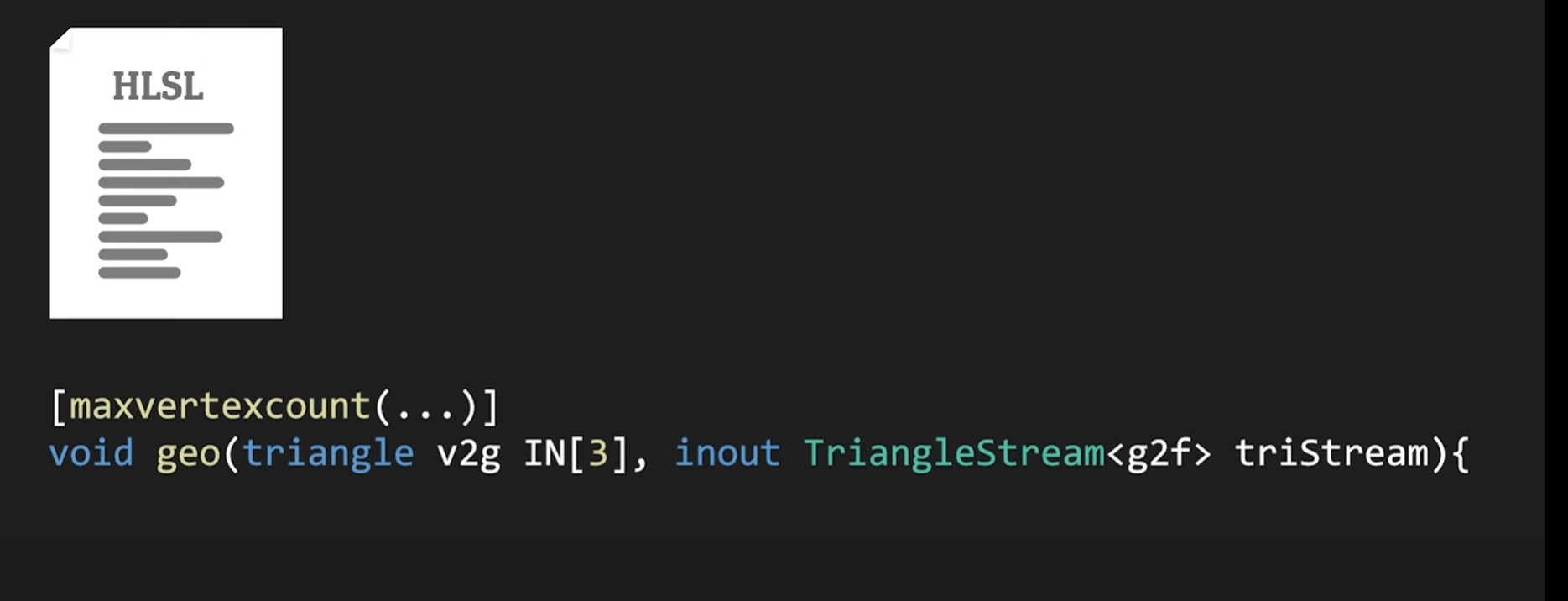
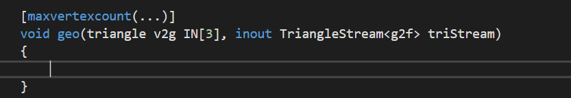
But what that does is insert a blit (grabpass) in between render queue operations. That's not really much different than this.
But otherwise, maybe try command buffers on the camera and do the grabpass manually?
Is there a specific place people recommend going to get a good highlighter for HLSL/CG?
Am using Visual Studio Community
So wait am I supposed to literally use .hlsl as a file type? https://i.imgur.com/7FHeZWG.png
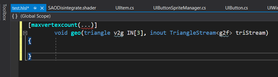
Unity makes it look like it doesn't recognize it 🤔 https://i.imgur.com/LVYW03L.png

Ah okie so I just need to figure out how to tell community to associate .shader files with .hlsl files
hmmm
Mostly figured out...now I'm just wondering if I need to do something special to make it recognize non-HLSL syntax that Unity specifically uses, because... https://i.imgur.com/bIxqvVO.png
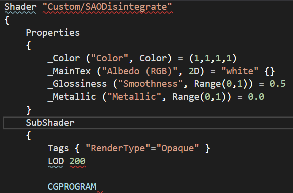
Extension for Visual Studio - This is Unity CG Shaders Support. It has code completion support and uses C/C++ like highlighting for *.shader files.
That 'non-HLSL' syntax was originally CG shader https://docs.unity3d.com/Manual/SL-ShadingLanguage.html but its now warped into Unity's own syntax
The non-HLSL part is unity's ShaderLab syntax, not CG
I tried that one originally https://i.imgur.com/f2Azdiq.png

But it's apparently not supported, which I presume means it's for VSCode, and I'm using VS 2019
Yea only works for older vs 2013 versions
@marsh merlin This might help, it's not 2D but I don't know why that would matter (I can't guarantee it won't though).
https://github.com/UnityTechnologies/LWRPScriptableRenderPass_ExampleLibrary

GitHub
Contribute to UnityTechnologies/LWRPScriptableRenderPass_ExampleLibrary development by creating an account on GitHub.
What memory management is available for Compute Shaders when I'm not using ComputeBuffers? Having my shader running for ~1min causes Unity to crash and I think it's to do with poor management of my shader
How are you sending data to your shader and where is your shader writing data
Input: Texture2D<float4>
Output: RWTexture2D<float4>
I'm using the shader.SetXX() functions to send data to the shader
I reuse the Texture2D and RenderTexture C# objects for every call
How do I go about handling a very large ocean
In terms of game performance
because you can make a massive plane, but to add normal sized waves onto it you need to subdivide it a bunch

More Game Art Tricks: http://simonschreibt.de/game-art-tricks
Article to this Video: https://simonschreibt.de/gen/stylized-vfx-in-rime-water-edition
00:02:50 Fire
00:07:00 Smoke
00:13:05 Water
This talk was given at the UnrealFest 2018 in Berlin/Germany. It's about the stylized effects from the game RIME.
Tequila Works: http://www.tequilawor...
This is a good talk about how Rime handled their water. You can see their mesh as well.
Alternatively, if your perspective never sees the horizon, then you can handle it similar to A Short Hike and just move a plane around with the character.
Not sure if this is the proper channel but why would standard shaders be unsupported on my iOS build?
V new to shaders and trying my best to figure things out slowly but surely...googling isn't helpling with this. I have a random function already that takes a float2 input, but how can I make the same equivalent take two separate float inputs?
float random (float2 uv)
{
  return frac(sin(dot(uv, float2(12.9898, 78.233))) * 43758.5453123);
}```
the point of this is to get a random number between a min/max rangeCheck your which renderpipeline you have
That function returns a random value between 0 and 1. Obtaining it between any min/max just requires a bit of remapping. Can do that using :
float random (float2 uv, float min, float max) {
  float rand = frac(sin(dot(uv, float2(12.9898, 78.233))) * 43758.5453123);
  return lerp(min, max, rand);
}
ohh
lerping between the inputs by the random number
that makes sense, thanks!
what exactly is uv supposed to be in this sense? I only care about the min/max. The old function that takes a uv input is from the shader I'm copying and attempting to modify 🤔
UV is any 2D coordinate used as the seed for the random number. If you pass the same two values in, you get the same values out.
Ah, let me figure out what they're passing in when they use the random function and I'll just pass the same then
Lucky me, I don't think they ever use these functions, so this must be from a template they used or made for themselves xD
hi all! does anyone know how to use a custom grass shader for Unity terrains in newer versions of Unity
in old versions you could bring in the built-in shaders and modify them. doesnt seem to work like that anymore.
i have to use built-in renderer btw... theres hacks for copying the URP built-in shaders... but i cant use those since the built-in renderer is not a package...
didnt realize there was a #⛰️┃terrain-3d section. will xpost there
Can you do soft particles in shadergraph?
there are a few ways to handle this, Unities Boat attack demo has an example which one could re-use or at least the principles of it. Simply put different sized grids with differing levels of tris. More dense ones nearer the camera and less dense further away, utilizing some form of LOD to keep performance up (tessellation could be used). Texture the ocean in world / absolute world space UV to avoid tiling issues where each mesh joins. You may still have problems at mesh edges / seams which can be handled in different ways.
The ocean effectively follows the camera around and you may need to use a different shader to handle water to horizon.
If you then want objects to float on the water and you've handled wave generation in the shader, it's best then to use a compute shader to handle physics by replicating that wave generation and querying points to ensure the timings match up. Making batched calls to the compute shader on a delay every few frames to keep performance up.
Crest or boat attack code is readily available to examine how they handle all of this, Crest also have / had a list of most relevant papers relating to ocean rendering in real-time which can be useful.
If that seems like a lot of work, trust me it's not as simple as it sounds. Then there are plenty of assets on the store to save time, sanity and make life easier 😉
yeah i mean i still want simplish water
im having a lot of trouble gauging what kinda of shader style I want for my game
What I try to do, is push forward the more tangible elements of the game and leave the aesthetics till later. But it's hard to do at times as just coding stuff gets boring 😆
The look is as important as functionality and story
our team manager wants us to create assets before coding
so I thought i'd work on some shaders to use for when we start building the world
just to work ahead i guess
Hey all, what is an efficient way in sending an input (Texture2D) to a compute shader?
Currently I use
SetTexture(kernel, nameID, texture);
but I need to do that really frequently with multiple textures at the same time, and that really decreases the performance.
I send other type of data with a buffer, is there a way to do that with a texture? I just need to read the input pixels in the shader
hey, i have a problem with shaders
wait
post processing is a shader right?
i'm using the latest version of unity
@tranquil bronze if depth is enabled on the camera you should be able to make a sampler2d called _CameraDepthTexture to access it https://docs.unity3d.com/Manual/SL-CameraDepthTexture.html
Unitys shaderlab uses hlsl as the shader languagr
alr
Cg is the meta data stuff wrapping the hlsl like Pass, SubShader, Properties, etc. The combination of Cg and HLSL is what Unity calls shaderlab.
something like this right?
float depth = LinearEyeDepth(tex2D(_CameraDepthTexture, IN.UV).r);
I get an error 'LinearEyeDepth': no matching 1 parameter function at line 127 (on d3d11)
Is UnityCG.cginc included?
That function might be gone in newer versions, follow the guide I linked above.
i included it but now i get more errors
@tranquil bronze URP uses an extra parameter which can be filled with _ZBufferParams. More info here : https://www.cyanilux.com/tutorials/depth/#sample-depth-texture
can you make a shader distort a vertex more than just up and down?
Vertices are just positions in space, you can move them however you want.
A height map, for example, is just a normalized value (0..1) which lets you multiply the direction of the vertice by a min/max amount. The direction doesn't have to be the world up direction.
also someone said that if i wanted a large ocean that the player can explore, i should have the plane follow the player
how do i make it look like the player is still moving through the water though
That was me, yes. As a way around needing to create a large plane.
@lethal brook similar to world space texturing, the oceans distortion should be based off the world position so moving the plane doesnt shift the water.
The vertex position for water is usually calculated in world space, so as the plane moves around, the water will look proper, basically.
oh I already had it like that, i didnt know it functioned like that, cool!
hm wait i want certain areas of the water to be darker, is there a way i can do that
not like depth fog or anything
i want the surface of the water to be darker in areas of my choosing, how would you go about doing that when the plane follows the player?
can you use shader graph in standard 2d or does it need to be in urp
ShaderGraph is only available in URP or HDRP
ok thanks
switching over some shaders from HDRP to URP. I see there is an emission Fragment output node, and I read that I need to use a bloom volume override to make the emission work- but I'm just not having ANY luck- anything else I should check?
you can sample a texture using world space (x,z) coordinates, as the lookup UV.
Emission still works without bloom, but you won't get any glow without bloom. Emission just adds self illuminating pixels, unlit basically.
Are you trying to get actual light emitting from the pixels?
@low lichen it's the glow aspect that I cant get to work. changing the emission changes the output color- but it ONLY effects those pixels- not neighboring one. I tried playing the bloom volume parameters, cranking some WAY up- but this still didn't seem to effect neighboring pixels. Could this issue be due to some OTHER settings, like say "exposure"? (not sure if thats even a thing in URP, yet.)
I don't need this "light" to illuminate objects- I just want that fuzzy glow effect
Are you getting any bloom from the lighting, like bright reflections?

prolly a better way to do it- but you could create a camera, and have it draw to a texture that you display in that mirror material.
@grand jolt there prolly IS a better way- like reflection probes or something- but I don't really know about those.
I was just making sure the problem was with the bloom itself rather than just the object
hmm, I DO see reflected light blooms in the sample scene. Don't think those use the emission node in the shader- but I guess this DOES imply something ELSE in the game scene is messing up the bloom. @low lichen
How does your custom shader look if you put it in the sample scene?
testing that now...
Emission is just color that's added ontop of the lighting color. What causes bloom is very bright pixels. It doesn't matter if it comes from Emission or just the lighting itself.
yes, my emission shader works well in the sample scene!
How do the Volume and Layer post processing settings compare between the scenes?
(does URP still have the Layer component?)
I DID use the layer stuff in HDRP- but for this test, I setup only ONE global volume for the game-scene- and it uses the same volumeprofile asset as the sample scene.
(no, I DONT think it has the Layer option anymore)
The layer thing is basically built into the camera in URP
other differenes between my scene and the sample scene- mine has no light probes or reflection probes- are these required for bloom to function?
oh, well I'm now using "overlay" camera for the UI- let me test to see if that's related. I'll try some other changes to & report back.
Any good resources for mastering compute shaders? I'm going thru one course atm but finding I'm not actually learning much by simply following along with the instructor, typing in code.
@low lichen thanks ANOTHER million! it was right there in the cam. Going to go whip myself now- cheers!
@low lichen FYI: one other camera option was needed to make the shader's emission intensity affect the size of the glow:
Can anyone here field a beginner compute shader question?
Is the basic flow for getting data into and out of a compute shader:
Script -> ComputeBuffer -> GPU -> ComputeShader -> Script ?
in other words, when a computeshader changes the values its computing, one accesses that output from the ComputeShader interface -- rather than the ComputeBuffer interface -- right?
another way of asking -- would it be correct to say that ComputeBuffers are one way communication from CPU to GPU?
and if I want to get access to the computed data, I would be reading data from the ComputeShader managed object itself, right?
You can read back from the ComputeBuffer but it can be slow
I don't think there's any way to read data from the ComputeShader itself
in general though - the whole pipeline is optimized for CPU -> GPU
getting data back from the GPU is going to be slow
how slow? I've never actually tried it
probably very hardware dependent
hmm. well, I suppose that's good info. Its basically between copying an array from the GPU back to the CPU or calculating everything on the CPU
indeed
so its either burst/jobs etc or compute shaders
don't forget about the jobs - yeah
I suppose you're saving me a lot of time if youre telling me its not worth the trouble
I already have it all implemented with jobs
its relatively fast, but I figured I could scale it more on the GPU
ideally you can figure out a way to do this such that you don't need anything to come back to CPU-land from the compute shader
How to rotate a texture in Compute Shader?
I have this code but it doesn't work...
Texture2D<float4> source;
RWStructuredBuffer<float4> pixels;

int angle;
int width; int height;

uint getPixelIndex(uint3 id)
{
    return id.x + (id.y * width);
}

[numthreads(8, 8, 1)]
void Rotate(uint3 id : SV_DispatchThreadID)
{
    int xcenter = width  / 2;
    int ycenter = height / 2;

    float radians = angle * (3.14159274 * 2 / 360);

    float s = sin(radians);
    float c = cos(radians);

    int xO = 4;
    int yO = 4;

    int xx = (int)((id.x - xcenter) * c + ((height - id.y) - ycenter) * -s) + xcenter;
    int yy = (int)((id.x - xcenter) * s + ((height - id.y) - ycenter) * c) + ycenter;

    uint index = getPixelIndex(id);

    if (xx >= 0 && xx < width && yy >= 0 && yy < height)
    {
        int i = xx * 8 + xO + ((yy * 8 + yO) * width * 8);

        uint3 uv = uint3(i % width, i / width, 1);
        pixels[index] = source[uv.xy];
    }
}
What doesnt work about it?
I have this random texture

and if I execute this code I get this result

Just a weird triangle missing from the texture
Does it work without rotation like
pixels[index] = source[id.xy];
Yeah then I just get the original texture
Try
{
    float radians = angle * (3.14159274 * 2 / 360);

    float s = sin(radians);
    float c = cos(radians);
    float2x2 r2 = float2x2(c,-s,s,c);
    float2 center = float2(width,height)/2,
pos = clamp(mul(r2,id-center)+center,float2(0,0),float2(width,height));
    pixels[id.x+id.y*width] = source[pos.xy];
}```I rotated the image 45 degrees and it is definitely better now! Although there's some weird effect created in the left bottom corner

Your rendering the rotated rectangle in a non rotated rectangle so it gets cut off.
How would I prevent this?
Do you want it to display black where its cut off instead of extending the image?
Just fully transparent. I tried this with a different image and there's some weird issues, do these relate to the same problem?

I had this as a source

The blue lines by his feet? I dont know what those are
Looks like it rotated fine though
Yeah the rotation works perfectly! Just those weird glitches
Thank you by the way! Appreciate the help!
Seems like when I rotate the texture in any angle there's always some pixels on the left side, although nothing on the right side

I think its the right side pixels bleeding onto the left side
Try changing the clamp to
clamp(mul(r2,id-center)+center,float2(0,0),float2(width,height)-1)
Is this for the pos variable? I changed it but seems to be the same, also there's some lines all around the sprite

Those above the head weren't there prior changing the line
Ohhh wait thats the clamping
pos = mul(r2,id-center)+center;
if (min(pos.x,pos.y) < 0 || max(pos.x-width,pos.y-height) >= 0) pixels[id.x+id.y*width] = float4(0,0,0,0);
else pixels[id.x+id.y*width] = source[pos.xy];```Nice! All the lines has disappeared! Although that left side thing is still there

After I dispatch this I use the other kernel to simply put the pixels to a RenderTexture
[numthreads(8, 8, 1)]
void Copy(uint3 id : SV_DispatchThreadID)
{
    Result[id.xy] = pixels[getPixelIndex(id)];
}
Whats the width/height of the image I think its because the width isnt evenly divisible by 2
The width is 652 and height is 817
I use ceil for the thread groups, cause otherwise the entire texture is not fully generated
threadGX = Mathf.CeilToInt(source.width / 8f);
threadGY = Mathf.CeilToInt(source.height / 8f);
Either make your image texture the full size of the thread blocks(threadGX,threadGY) or at the beginning of each shader add
if (max(id.x-width,id.y-height) >= 0) return;
I think just making the texture bigger is more efficient.
Like this? It doesn't seem to be doing anything after I have included this

If that doesnt work I dont know it should stop the thread blocks from executing outside image bounds.
I tried adding the opaque black color if the condition is true and that resulted in the entire texture being covered up
if (max(id.x - width, id.y - height) >= 0) { pixels[id.x + id.y * width] = float4(0, 0, 0, 1); return; }
This does not make sense to me...
I tried using a different size texture, width 600 height 230 and there seem to be no issue
Well I kind of fixed the issue by adding
|| id.x >= width || id.y >= height
if (min(pos.x, pos.y) < 0 || max(pos.x - w, pos.y - h) >= 0 || id.x >= width || id.y >= height)
{
    pixels[id.x + id.y * w] = float4(0, 0, 0, 0);
}
else
{
    pixels[id.x + id.y * w] = source[pos.xy];
}
However it seems that the left side is missing 4 width pixels

Or rather it's shifted by four pixels. I tried adding a colour instead of a transparent one and it seems that the image is shifted to the right

I'm not very familiar with how to debug shaders or write shaders in general. But im trying to get a shader i found working so i can learn more about it. There's a specific line however that is giving me the: "error cannot implicitly convert from 'const half3' to 'float4'". the line is i.eyeVec = NormalizePerVertexNormal(snappedWorldPos.xyz - _WorldSpaceCameraPos);
also snappedWorldPos comes from float3 snappedWorldPos = originalWorldPos + dXYZ;


because you need to Sample Texture 2D LOD to use a texture sample in the vertex shader stage
HI, any idea if is this possible to create with shader? the idea is puting this into a sprite and put public the fields to modify by script, any idea to solve this?

this is an audio spectrum
it's possible to create, here's an example of such a shader https://www.shadertoy.com/view/ldtBRN

hi, can anyone help me please
is there anyway to make effect for few element, not whole screen like post processing?


can you have shaders only affect specific object layers?
layers as in what sense?
why not just post process the individual mesh or quad or whatever it is
another way is to use masking
basically white for places that you want to affect and black for places you don't want to affect
as in... the layers

oh i see
thanks for your advise, these hairs is made by line rendere
and i dont know how to masking or mix the square image only on hairs
technically you will need to tell the shader manually from the CPU
do you have any keyword pls
im not sure about line renderers
but maybe you can do it by rendering it at another camera and apply the post fx on that camera only
then render it on top of this pic
what a great idea
I also got a question, is #pragma once available in shaders in unity 2021.1.0f1?
i will try your idea after test few ideas (i got them after asking those question)
thank you very much
sure, but... how?
read the layer using C#
create an int in shader
material.setint 1/0
remember to use material and not sharedmaterial
and it will only work in play mode not editor mode
does anyone know why colors might be different when drawing a mesh with a mesh renderer vs commandBuffer.DrawMesh, when the project is set to linear space?
it's definitely a linear vs gamma conversion issue, but in this case they are both draw using the same color, both using a materialpropertyblock to pass it in, and yet they look different
the cmdbuf drawn one has the same float values as the color field is displaying, while the mesh renderer one seems to have been gamma corrected/been darkened before render
do I have to compensate for linear/gamma manually when using command buffers?
ah, found it!
now I have a separate issue
why is there no mpb.SetColorArray? D:
hello, i'm new here
in my game i made a big island but now i need the ocean, and all the tutorials that i watched needs shader
can someone help me?
i never used them before
"hi, how to learn everything about a topic?"
What is your question. Do you want us to point you in a direction of tutorials?
Do you want to learn shaders?
Im afraid shaders is the only way to create your water
do you need height maps for hdrp shaders
Yeah
I want to learn the basics of shaders to understand all the tutorials
Okay. So as for unity there's several things you can do. The most beginner friendly way is to learn one of the visual graph editors such as Unitys Shadergraph. It can do quite a lot of things.
https://www.youtube.com/watch?v=Ar9eIn4z6XE this video is slightly old but lots of the things in it gives a good idea of what it is and what it does and how to use it
● Check out Bolt: http://ludiq.io/bolt/download
The time has come... Let's explore Unity's new Shader Graph!
♥ Support Brackeys on Patreon: http://patreon.com/brackeys/
····················································································
♥ Subscribe: http://bit.ly/1kMekJV
● Website: http://brackeys.com/
● Facebook: https://f...
Other than that i encourage you to go hunt for tutorials on the topic
If you're more into "programming" you can code your shaders too, i believe unity uses HLSL. So go look that up if thats something you want to do
Ok thank you very very mucj
Ok
And since you want an ocean shader: https://www.youtube.com/watch?v=Awd1hRpLSoI&t=5s https://www.youtube.com/watch?v=IbfvxelK6ok

The Goal of this Video is to show you how to create Gerstner Waves for an Ocean Shader with Shader Graph in Unity 3D.
It also includes a way to calculate the vertex normals of the ocean shader at 7:30.
Please let me know if you like more of this.
Maybe I can go into more detail in other videos and show you how I achieved other effects like the...

The goal of this Tutorial is to make the previously created shader actually look like an ocean. I used three common Techniques to make that happen.
This tutorial is based on the previous video, but you should be able to follow along without it.
I'm using the newest Unity Version and HDRP, but most of it should work with URP too. I also recomme...
Those are fairly advanced
But they are pretty much just a walkthrough
I recommend you save these for later, until you've learned some basic things
ok
Im seeing a lot of tutorials advice to use PBR graph (for URP). Idk if it was updated/renamed to something else in 2020.3LTS?

These are the options i have
It was renamed to Lit
How I can disable shadows filtering in HDRP? 🤔
@regal gorge No according to this all you can do is change quality of the filtering, the lowest quality still has filtering https://docs.unity3d.com/Packages/com.unity.render-pipelines.high-definition@10.4/manual/HDRP-Asset.html#filtering-qualities
Maybe try setting it to High quality then lower 'Filter Sample Count' under Light component settings.
I've got a tesselated plane i created in 3ds max. Whenever i apply my shader (which modifies the vertex position) it just goes completely invisible. if i stop modifying the vertex position it comes back. I feel like it's an issue with the mesh itself and not the shader
Any ideas?
What happens if you apply it to a different mesh?
That sounds more like a shader issue. How exactly are you modifying the position?
Im following this https://www.youtube.com/watch?v=Awd1hRpLSoI&t=5s
The Goal of this Video is to show you how to create Gerstner Waves for an Ocean Shader with Shader Graph in Unity 3D.
It also includes a way to calculate the vertex normals of the ocean shader at 7:30.
Please let me know if you like more of this.
Maybe I can go into more detail in other videos and show you how I achieved other effects like the...
@regal stag
Yeah it might actually be the shader. I tried applying it to unitys 3d sphere, which also didnt work.
Then its your shader.
Sorta odd. I'm 99% sure that everything in my graphs/subgraph is exactly the same as in the tutorial
To find what specifically is wrong you will want to work backwards and toggle nodes that connect to the output, when you remove one and it displays properly it your error is from that node.
@sinful arrow nothing happens I would like to have more control on that in future.
The irony of scriptable pipelines offering less control....
