#archived-shaders
1 messages · Page 193 of 1
i tryed to get a random on the triangle location and use the localpos.xyz as seed to have the same value every time, but it gives the same result as positionWS somehow and so the random changes every time the triangle moves in the world 🥺
im wondering how i could get a ONE TIME random for every triangle in the geometry shader if anyone has an idea
preserved over every following frame of course
Anybody got an idea why when I have generated normalmap used in Shader Graph, one axis gets inverted, I have clean Vertex Normal and Tangent so they both match, but they only match in one direction, it seems like Bitangent is inverted but how do I modify bitangent?

Found fix, If anyone has this problem then terrain is for some reason taking inverted normals, so either try multiply X or Y by -1 of the unpacked normal map
found this on the internet -- if anyone needs a shader where the object is always facing the camera

Does anyone know the equivalent to Blender's "Darken" and "ColorRamp" in Unity Shader Graph?
How are you grouping nodes like that?
Im trying to get started writing a compute shader, i have an algorithm i need to run on every value of a 6dimensional array, but i dont know how to have a shader do that, and doing it with a massive nested for-loop seems atrocious
Anybody know way to find all shader graphs' used the subgraph? Currently i replace subgraph file from project and see on shader graph errors in console, but that is small confused and look not as "correct way".
if you select multiple nodes, right click and towards the bottom theres an option to group the nodes. .
uhm guys, does shader graph has problem with setfloat going from 1 to 0? I'm trying to do a dissolve back but the effect refused to run
I'm trying to make a function node , how do i read those errors ? doesn't tell me much about anything
Shader error in 'hidden/preview/RadialBlurCustomFunction_b6a14967fbbd4143b9294e091a5245e1': undeclared identifier 'RadialBlur_float' at line 157 (on d3d11)

that's my node settings

and the function itself

undeclared identifier 'RadialBlur_float' means it cannot find a function with that name, because in the file you've called it "RadialBlur". It needs a precision type appended, either "_float" or "_half" depending on the precision of the custom function node (default is float).
so do i just change the function name to RadialBlur_float ?
Yes
it doesn't work :<
oh it does
i just see another error lol
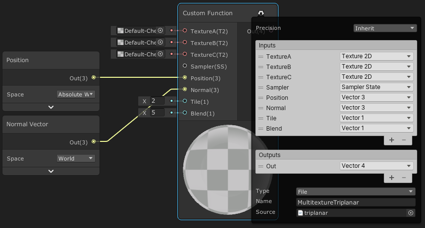
cannot convert from 'const struct UnitySamplerState' to 'SamplerState'
is this a URP thing ?
Ah, you're in v10.3+, they changed the texture and sampler types to make them better to work with
i see
You should use UnitySamplerState instead of SamplerState, and UnityTexture2D instead of Texture2D
10.3 it's for the package version , yes ?
It means though, that if you want to use the sampler from the texture you can now, with MainTex.samplerstate though, so you might not need the SS input
Yeah these were 10.3 changes, the function won't work if you make those changes and want to use it in versions prior to that, you'd have to go back to Texture2D/SamplerState instead of the Unity_ ones.
I mean that you might not need the SS input at all, instead just do SAMPLE_TEXTURE2D(MainTex, MainTex.samplerstate, coord); and it'll use the sampler from the texture. Unless that's not what you want of course.
i see , may its better
it does work now

was trying this one out https://gamedevbill.com/custom-shader-graph-nodes/
thanks @regal stag
how do i convert float2 to make it a UV input ?

Currently isn't possible, it's planned for sub graphs though
For now, you just have to connect a UV node
so its only a (visual) node thing , i mean it doesn't impact the calculations ?
Yeah
i see , thanks
Hi, i'm trying to find a shader that create something light beams like this https://ibb.co/z6wdMYC
And same lasers like this https://ibb.co/LCTwdC9
I know there is a payment way but i can't afford to buy it now
But i the only problem is i need to use a Render Texure for the color.
I can give more info if you need just MD me.


@left stump for the 1st one i would try making a cylinder shape with the top part having a smaller radius , and making a transparent shader that move a noise function as time passes , and apply a gradient with HDR with tiny step and without hrd for the rest of the shape to make that light at the edge popup / or just add a source or light instead , for the 2nd one u could simply use a line renderer with white as its primary color and purple as the outline color , idk about the blending area near the tip that make it look like a triangle tho ?_?
The lasers that you see, they change colour with a Render Texture, and it's a plane but i don't know how to code :c
any one knows how to make phat lines ? is there a blur method in a node or is it better to write a custom function that scans the neighboring cells and sharpens the edges ?

This is pretty basic, I am not using any graphs so far but does anyone know why the colors won't project onto the planes?

Hi!
(I'm using the hdrp)
Sooo i'm looking for a way to render some extra things on some objects
I want to draw procedural slashes form a sword on enemies. for this i store the slashes start and end points on the object.
I found this for passing in the data. But not sure how to add the render pass to it.
https://docs.unity3d.com/2021.1/Documentation/ScriptReference/MaterialPropertyBlock.SetVectorArray.html
I did find this : https://docs.unity3d.com/Packages/com.unity.render-pipelines.high-definition@7.1/manual/Custom-Pass.html
But not sure if this is the right thing
(ping me if you reply)
okay i don't think there is any way to get the GO from the render pass
(witch does make some sense)
soo i would need to
A) add the extra renderer to the default shader, like make a variant of it or similar
B) maybe add the objects that need it with some render command in the update
I'm moving vertices using shader graph how can I paint the strength at which they're moved?
My idea was to paint colours between black and white on a texture and then multiplying the movement with the strength reaching from 0 to 1 but how can I do something like that?
a bit of an issue -- transfered some shaders from an test project, the generated shader code from the other project doesnt work with the current version, and unity has removed the ability to copy the shader code
wanted to edit ztest to off. .

It's moved to the inspector when you select the .shadergraph file

oh thx! thought i was strung outa luck
Could anyone guide me towards a good tutorial for water physics?
Is it possible to have decals in URP?

Yes, some assets exist, paid or free, but nothing native in URP for the moment
oh, right
https://assetstore.unity.com/packages/tools/utilities/ultimate-decals-deferred-forward-urp-139080

Use the Ultimate Decals (Deferred, Forward, URP) from Bear Roll Studios on your next project. Find this utility tool & more on the Unity Asset Store.
Hello.. I'm trying to make part of a decal transparent using an alpha map. Instead of being transparent its showing black. Anyone know what I'm doing wrong?

You're looking for alpha-clip. The "how" varies by what pipleline you're using.
Use alpha clipping?
I have clipping checked, I don't see any difference between 0 and 1
What form of render pipeline closely reflects the shader-node style of Blender? I'm trying to duplicate my shader I used for Blender, rather than just baking everything in.

Or how exactly would I get to a point I can do shading setup similar to this?
Use shadergraph. Bundled with URP and HDRP.
Oo kk thank you
This is probably a nonsense question, but is shadergraph/ URP/HDRP really taxing when it generally comes to rendering a world? Like I feel like if I wanted to make a game for mobile baking in from blender will probably be the only truly manageable way.
is there something similar to tesselation / subdivide node in URP?
i made a heightmap shader but its really blocky, i mean it obviously has low amount of triangles (i'm testing this on a quad now)
this isn't possible with URP, right?
Use URP if you are doing something for mobiles, also its up to how optimized will be your shaderGraph setup, its not taxing at all when used correct.
There is no node in shader graph similar to tesselation, however you can try this tutorial https://www.patreon.com/posts/basic-setup-in-45320078
just in case you are working on a terrain and are later thinking about adding a mesh collider so you can have some kind of player controller on it, you should know that a shader that changes the vertices of a mesh wont affect the mesh collider and it might have other limitations ( im not very informed so there might be some kind of workaround )
yeah, that method is heavily limited for other reasons as well. i really don't want to go down the collider only route
thanks for this, i'll check it out
Nice. Ty. I'm using a toon like ghibli shader, I'm not particular on the dos and don't tho
hello! im a complete newbie to shaders, but i was wondering, given this example where i have 2 intersecting spheres with inverted normals, if it would be possible to remove the parts of each sphere that intersect? ideally, if one sphere enters the radius of another, the vertices that intersect should be cut off (i will only ever be doing this with spheres, if that helps). if anyone knows how to do this or where i should go to learn, please let me know :)

what's the desired result? To see emptiness in that middle section?
the player will be inside the spheres, so they should be able to see from one sphere, through the intersecting area, and to the other sphere
so in this case i guess i'd want it to show the parts of the sphere that are behind the other sphere? it would be a bit like a boolean addition, if that makes sense
Hey all, I'm relatively new to shaders and wondering if I could get some help with trying to solve this issue. I've got a dissolve shader that once a mesh is disolved, i'd like it to continue to cast shadows. I've been able to achieve that by making the Surface transparent, and passing my cutoff into the Alpha Clip Threshold as well as my Alpha. However, as you can see in this video, i'm getting some issues that i don't fully understand, though know it's related to the Alpha Clip. I don't get this issue if I leave the shader surface Opaque, however I no longer get the shadows from the dissolved meshes. Can someone point me to some reading or offer advice on how i'd be able to solve this? Here is the Shader graph:

Does anyone have a good rundown on making URP screen effects?
Anyone have experience with Replacement Shaders?
I'm trying to figure out how to make a transparent shader turn opaque using them. I need the Camera's depth buffer to reflect this change for a post processing effect though
I have one here, though perhaps a little outdated : https://cyangamedev.wordpress.com/2020/06/22/urp-post-processing/#CustomEffects
In short, for fullscreen effects you can use a Blit in a custom renderer feature (which basically draws a quad with the source texture to the destination target, but a material/shader can also be applied). Unity has one here : https://github.com/Unity-Technologies/UniversalRenderingExamples/tree/master/Assets/Scripts/Runtime/RenderPasses
(that version likely only works in v10+, can switch the branch/tag if you are using an older version. I also have one here : https://github.com/Cyanilux/URP_BlitRenderFeature for v8).
You can assign a material/shader to the feature that uses _MainTex to grab the source input. Can even use shader graph (unlit graph).
There should be an option on the Mesh Renderer to disable casting shadows which might be easier than editing the shader. But if it's a code-written shader, for vert/frag there will be a ShadowCaster pass which is responsible for casting shadows. Without that pass it shouldn't cast them. If it's a shader graph I don't think there's a way to toggle it though, other than on the renderer.
Transparent objects don't write to the depth buffer so cannot always be sorted correctly. It's best to always stick to opaque. I can think of two ways to fix this :
- Duplicate the floor gameobject, assign a normal lit material and set it's Mesh Renderer to Cast Shadows Only, that'll make the object invisible but still cast shadows. You can then disable casting shadows on the dissolving object.
- Or, Using a Custom Function it's possible to change the output of the shader for it's ShadowCaster pass compared to the regular pass. This would allow you to set the alpha clip for the main one so it dissolves, but leave the ShadowCaster at 0 so it always casts shadows. I have a tutorial that includes a section on this here : https://www.cyanilux.com/tutorials/intro-to-shader-graph/#shader-pass-defines
But I'll post the code here too (slightly edited) :
#ifdef SHADERGRAPH_PREVIEW
    Out = 1;
#else
    // For URP this is needed :
    #include "Packages/com.unity.render-pipelines.universal/Editor/ShaderGraph/Includes/ShaderPass.hlsl"

    // Test if we are in the SHADOWCASTER pass
    #if (SHADERPASS == SHADERPASS_SHADOWCASTER)
        Out = 0;
    #elif (SHADERPASS == SHADERPASS_DEPTHONLY)
        // might also want to treat this one as no clipping.
        Out = 0;
    #else
        Out = 1;
    #endif
#endif
Custom Function using String mode (so it's contents is edited via Graph Inspector). Either replace 1 with an input or Multiply the output with the Alpha Clip value before putting it into the master stack.
@regal stag Thank you! I'll need to check that out.
How about rendering an outline around an entire particle effect?
Basically I wanna continue the arm outline around the particles along the open end https://i.imgur.com/PSnUjlR.mp4

Or alternatively how to draw a duplicate of the particle system with the same random seed
Can I just set the seed to the same in both and have them match?
hrm, nope
Solved it. Apparently particle noise isn't based on the seed of the particle system o.O

@regal stag Woo! Thanks so much! Took me a second, I was misunderstanding what you were saying, but the opaque shader solution worked perfectly! There was an issue with the SSAO still showing but that was because the source was set to Depth. Setting Depth Normals fixed that! Your site is also great! I've been looking for some good resources, so this is a treasure trove 🙂
does any one have a good shader code recourses?
Hey,
It's possible to send data from a MonoBehaviour-script to a shader. But is it also possible to retrieve such information, for example how much of an object's surface is receiving shadows?
Using the URP here
Material property blocks or Global properties can be used to pass data into shaders, but how I have no idea how can you retrevie aswell.
Hi 🙂 Very quick question: why doesn't unity_ObjectToWorld work at all?
It should work, unless the object is static or dynamic batched (https://docs.unity3d.com/Manual/DrawCallBatching.html), or a Particle System or Sprite (likely due to batching again). If it's one of those the transformation is already applied to the vertex shader input and unity_ObjectToWorld is set to an identity matrix.
Even if that were the case, the result should still be correct, right?
Of multiplying the input vertex by unity_ObjectToWorld
If it's the identity matrix then multiplying shouldn't change the input vertex position.
Whoops sorry, my mistake. It's not unity_ObjectToWorld that isn't working, it's WorldSpaceViewDir
I've been rendering out values as colours for debugging, and had the wrong value output. Yeah, it's WorldSpaceViewDir that doesn't work.
Is it okay to post an image to show the problem?
Yes, an image might help show it better
not sure if this is about shaders but is there anyway to get real time raytracing on the latest hdrp package for unity 2020.1.17
OR I could just stop being so goddamn stupid and read the definition of the function
I saw 'worldspaceviewdir' and assumed it wanted a WORLD SPACE input. It doesn't.
Be aware that a vector contains negative values so might show as black depending on where you are looking at the object.
Yeah, you wouldn't think it but this is not my first shader rodeo 😄
Ah right, yeah WorldSpaceViewDir needs the localPos. There's also UnityWorldSpaceViewDir which takes a world position to make it more confusing though 😄
Yep, that's sorted it. God I've been stuck on that for two hours
I think it is recommended to use the UnityWorldSpaceViewDir one instead as then you don't have to do the matrix multiplication twice
I really need to know this not sure if this is about shaders but is there anyway to get real time raytracing on the latest hdrp package for unity 2020.1.17
Possibly, if I also needed the world position, but in this case I don't.
I am not familiar with HDRP enough to really answer, but the docs page suggests there is some raytracing things in preview (e.g. shadows, global illumination, ambient occlusion, reflections, etc). https://docs.unity3d.com/Packages/com.unity.render-pipelines.high-definition@10.3/manual/HDRP-Features.html
It also links to pages where you can likely find more information
Thx for the help but there is a raytracing option it just says that it's not built in with the current unity asset
You should check that last link I posted to ensure the setup is correct
hi have this error in my shader
Shader error in 'Water': 'vert': output parameter 'o' not completely initialized at line 69 (on d3d11)

anyone know how to fix?
@stray kiln Assuming this is a surface shader, either remove the out Input o if you aren't setting any custom values, or add UNITY_INITIALIZE_OUTPUT(Input,o); to the function.
yes its a surface shader
I'm generating a lot of small tiles from a single prefab, but I want each prefab to have a slight difference in the amount of dirt it has on it, which I'd like to randomly generate with noise. Is this something best handled in a custom shader, or a secondary map, or another approach altogether?
Global constants don't work in compute shaders?
I get different results here
// Global scope
const float3 V1 = float3(0,1,0);
// Inside main()
    v1.positionWS = start + V1;
// This is not equal to
    v1.positionWS = start + float3(0,1,0);
@regal stag ty mate that worked
Is there a way I can apply render scaling without the need for a scriptable render pipeline?
Hello, I think i have a potential issue with the URP interfering with my particle systems. I made a shader using the URP and my particle systems that once worked before don't render properly as shown below. How do I fix this? https://gyazo.com/1ebbbdc70f37787bc1a35986543eb58b
Am I able to make a shader that sets a bilinear filter?
float refers to a 32-bit method of storing decimal numbers, in a "floating point" format.
float4 is a vector extension of that, where it has 4 of these float numbers. Usually labelled as RGBA as shaders deal with colours a lot, or XYZW which is commonly used for positions.
float3 and float2 are the same, just with less components, so only RGB/XYZ and RG/XY.
If you are familiar with C#, the equivalents are basically Vector4, Vector3 and Vector2.
Omg the the W is chasing me whenever i go
there is only 3 axis in unity so why float 4 ?
Like I said, shaders deal with colours a lot which includes an alpha channel (e.g. to handle transparency). That's the most common use for the A/W component. It's also used in graphics during rendering with a perspective camera projection. But any four float values could also be packed into a float4, they don't have to correspond to a 3D position.
thanks for your help
what does public in c sharp mean?
It means that the thing that is public is accessible from any other class in the program
Not sure what that has to do with shaders though...
thanks!
How can I have my shader render on top of everything?

Does anyone know how I can get this alpha shader to stop rendering on top of itself?

It seems to arbitrarily decide which faces render in front
So it looks like a mess
sounds like it's transparent rather than alpha cutout, which would cause z fighting.
If the render queue on the material is 3000 or greater then it's transparent.
You need to adjust the shader to correctly set it to opaque alpha cutout to fix the fighting issue as this will use depth correctly.
Can I fallback when target 3.0 is not supported in some devices?
#pragma target 3.0
Does Mobile/StandardShader have target 3.0 or 2.0?
and I have written an offset shader to solve z-fighting
I want to change it for example from (1,1) to (-1,-1) when it flips or the camera view changes (front to back face), Can I do that?
@thick fulcrum You were exactly right. Thank you :]
Where is graphics emulation in Unity2019?!
hi, does anyone know if its possible to access meshes/renderers bounding box values in shader graph? im trying to mod vertex positions relative to the objects center position, without manually setting the property for each object
Im trying to make a basic lambert shader on HDRP started from an unlit node but this doesnt work for me.Any ideas?

If you can set the object's center to its geographic center in the model, you can just use object-space 0,0,0 to calc it. (well, the verts would already be relative to that, no calc needed, just use the object-space vert value).
Has anyone found a way to create a "render scaling" feature in a shader WITHOUT the need for an SRP such as LWRP?
One thing I can tell you is that you should use #ifdef in place of #if
Is there a way to override a hidden shader? Eg, the WavingGrassBillboard shader from URP has ColorMask RGB, so it doesn't write the alpha channel. It's a simple change to make it write alpha, but if I edit the shader file unity just overwrites it again
Is there a way to combine a geometry shader with a lighting based one?
Can someone help me with this please
I want to be able to edit this shader graph variable from a script

blinkRenderer.material.SetFloat("Alpha", 1);
I tried this but didn't work
You need to use it's Reference not the name of the property. It's currently set to Vector1_A58445DF but you can also change that to something more readable, e.g. _Alpha. then use that same thing in the C# code.
Yes many shaders include both a vertex shader and a fragment shader
how do I combine the 2?
@regal stag It didn't work
    private Renderer blinkRenderer;
    // Start is called before the first frame update
    void Start()
    {
        blinkRenderer.material.SetFloat("_Alpha", 1);
        blinkRenderer = GetComponent<Renderer>();
    }
Shader Graph or custom written shader
omg.. I set the float before I get the component. Sorry for the @
Yeah it works. Thank you!
have you done this before?
Does anyone have a way to make Metaballs in the modern URP 2d renderer?
Every setup I've found breaks when I set things up for lighting.
so a shader i finished over the last 2 days I'm proud of, its a resource collection storage pod (the decorative metal bits outside arent here yet, just the container) the geometry shown here is a simple elongated sphere, completely smooth, no internal geometry or anything. I got it to be able to have ore add into it from the bottom up, and have a cool internal glow, and look like it has depth thanks to some parallax stuff. it reacts to environment lights and shadows only against the ore bits, and the internal glowey bits don't as they are supposed to be lit internally... overall came out nice. originally had the reveal wipe using visually individual chunks of ore, but it was to large of a granularity, so it doesn't really follow the visual chunks but mostly still works, easy to change it back just a single texture map change to a different gradient.
https://www.youtube.com/watch?v=q7gmlPckHr0

fully smooth spherical shape all depth and resource and shadow and glow is full inside the single shader
had to edit together several screenshots to get a big image out of the shadergraph editor (future feature maybe?) but its not a super complicated graph. the only custom nodes i have here are a simple 3 point gradient, because the inbuilt gradient function A) can't be manipulated by external c# code. and B) they tend to lose their color settings randomly and go completely white. and it could be more efficient, but i will improve it later. (pay no attention to variable names, they make no sense cause they got re-used and moved around a lot)

I am trying to replicate this grass overhang that can be seen in the bottom picture.
So I've been working on this technique trying to figure out how it was accomplished, and I'm not terribly familiar with shaders, but I wrote one to try and replicate this.
The top left is the masks, the top right the attempt with textures, which in this picture doesn't look terrible.
However the issue i'm running into is stretching with the edge. If the normals are not consistent like this, as I am just using world normals and a dot product to detect which texture to sample.
Ignore the textures, but I'm struggling to keep the overhanging grass a consistent height and not stretched, does anyone have any thoughts on how this was accomplished?
Could I be sampling the texture incorrectly, or maybe there is a technique to keep a textured area the same height in worldspace rather then object space?
I see a seam in the screen shot, could it also just be a UV trick rather then a texture rendering technique?
I feel like I'm close to getting this to work and would like to hear any thoughts on how it was done, or what I might be able to explore to get it closer to the result.
Two examples of the inconsistencies to follow


Okay odd question, maybe
How could I create a shader that mocks an unlit shader, that brightens and darkens according to the light?
Or maybe put more accurately, is it possible to average out the light hitting the object?
So it all brightens and darkens at the same pace?
I guess you'd basically just have the fragment shader read the lighting information from a single point no matter where the pixel is on the model. Not 100% sure how to go about that
Yeah it's a weird problem, I've been trying some hacky workarounds like raising the dark spots' emission so the shade is less apparent
But then obviously I have the problem of the brightness being raised when it exits the light
@mossy cobalt you can take the position of the light, color and intensity, pass them into variable in the shader and take inverse square distance to the light point (point lights) then multiply by color, intensity, and you could even drag in "range" depending on how you wanted to react to light settings. using "position (world)" node gives you calculations based on actual world position of each pixel so the object is lit based on how close each little bit is to the light, whereas using "object (position)" node calculates ALL pixels for the object based on its position point, so the whole object is the same color, but affected by the lights its tracking

for each light you want to track, then just add them all up before dumping into color output unlit master node


Wow that's beyond my expertise perhaps, haha
If I'm understanding correctly, you need to configure which lights specifically to take the parameters from?
its actually super easy once you think in how stuff works. manipulating shader stuff from code is SUPER powerful, makes stuff very dynamic
your code can just have a collider following the object and have it test for any lights within that collider, then just pass however many lights your want to track, starting with closest,
depends on what look you want to achieve in the end i can't imagine its a super complicated visual game, but i don't know what your building
have the shader be "able" to handle up to 5 lights or whatnot, and if nothing is passed in, set those lights to black when you feed the shader, so the object doesn't react at all
Yeah the code part is my weakness! I'm just an artist, haha
its always something to play with if for no other reason to be able to talk to whoever your working with and being able to talk their language and work through what you need from them, or understand what they need from you. crosstraining is always good 🙂
@fluid peak Very cool, but maybe enabling backfaces for the ore would help show that it is a container, rather than just a surface change? Also maybe still show the glass on top of the chunks; right now it kinda looks like a coating rather than stuff inside?
Im trying to create stylized Shaders(In Shader Graph) who is the best Content Creator to learn those Things?
Don't know who's best as that depends on your preferred style of tutorials/content, but I've got some tutorials here : https://www.cyanilux.com/contents/. Also check out https://minionsart.github.io/tutorials/, they do some shader graph ones, and https://danielilett.com/. There's also a few youtube creators I'm sure you can find by searching something like Unity Shader Graph.
Why is this pink ?

Thank you
i have a lightmap.png default texture type file that's 1x1, and at game launch I have a script that resizes it and SetPixels to fill it with RGB values as light blockers to be read by my shader. however when i start my project and hit play, it always does this weird thing in the scene view and i have to fix it by reimporting the shader

It's like _TexelSize doesnt get updated in the shader when the file gets resized
@regal stag Your work looks awesome!
Thanks 🙂
it's definitely the lightMap.Resize() step that doesn't update something properly 🤔
Anyone got a good wireframe shader? Just want to show the edges, but I cannot seem anything that I can use in shadergraph. Just bought an asset and it is not even working with the standard unity meshes...
well... for some reason not having the lightmap file assigned to the shader and applying it via code fixed it, even if i "reapplied" it before too after making the changes. Don't get it but it works.
How can I make a shader that puts a texture to the intersecting faces with shader graph in HDRP ?
@frank trellis a couple of possibilities, most commonly its referencing a texture that no longer exists. or there is a math error like a division by zero, could be there are too many texture samplers in a single shader (i think its like 16 or so but at some point it will throw a fault). very unlikely but that is an actual color that can be the legitimate output but if your not expecting it, then probably not
@eager folio I am gonna see what I can work into it, but there isn't any separate geometry for the ore bits, its all a single surface. should be possible but I gotta play with it

How can I set my shader to render on top of everything?
I'm using an unlit shader graph
I'm trying to create an unlit shader for HDRP but the exposure of the world is affected when I get too close to an object with it. Any tricks to fix this?

Whats the shader node called that mixes two colors based on a value
at .5: 50% a and 50% b, at 1: 100% a
Is the standard shaders here to stay or is unity pushing it to the urp and hdrp pipelines?
Yes
How I can create such a custom skybox (2 sided, top and bottom)

It looks like you already did?
nope its some image from internet
How can I make it such that my buildings are not see through?

That looks like a render order issue?
Hmm..it is a demo scene from a package I have.
UV or Position XZ / Y then sample a grid texture would get you quite close to that.
@frozen mason Maybe something like this

Awesome @regal stag gonna play with this! Thank you
Oh, fixed this by changing shader to Unlit Universal Render /PipeLine
@regal stag how you create those anchor or whatever it is so you can alter line path
It's in v10+ only, but double click a connection, (or right-click the connection and select it from the dropdown)
I'm working on a shader to blend 2 textures using noise but as you can see the pattern of the noise repeats is there a way to fix that I was thinking it might be possible to add world position to the noise but I'm not sure if that would work

this is the noise part of the shader the clamp connects to a lerp with the 2 textures

you can use 2 cordinates of the wold position node as the uv for the noise
do you mean like this?

How do I add comments to the shader graph?
right click "create sticky note"

When I set my shader surface to transparent, cameras higher on the stack render completely on top of objects with the shader, even though I've not set Clear Depth on my overlay cameras.


Am I misunderstanding something?
Transparent shaders usually do not write to the depth buffer
Is there a way to make it do so, or act like it is?
😮 i think i got it
nope, just made them opaque again 😂
You can add a render objects render feature, and render that object with an opaque shader that only draws to the depth buffer
thats what im trying now
i tried this but it doesnt work. does someone know how else i can do this?
I downloaded an Asset Store package with shaders that work, but the shader says it has errors. Should I fix it? If so, how? It works perfectly fine except for the errors.

i think i have it "working," but the cameras higher on the stack dont blend properly with the transparent shader, they just disappear when behind a transparent object 😩
theres probably a better way to do what i want without a camera stack >.>
i have a group of cubes aligned with a 3d grid, arranged like a rubiks cube.
i want to make one "layer" of the cubes render normally and darken all others, so i set up a camera stack with a post processing effect on the lower camera to darken cubes, and i swap the cubes between the camera layers when they need to be lit vs darkened

like that. is there a simpler way to do this without multiple cameras and layer swapping?
Hello, any Idea why would only one shader get GlobalMatrix? I am setting it and only one shaders receives it, others just get 0 in all Matrix fields.
Does having a transparent material decrease performance if it's alpha is 1?
I've got lot's of windows on my VR house and I want to basically make an LOD system for the windows
Instead, I thought maybe I could lerp the alpha as the player gets away from windows
@loud remnant I would change its LOD for Opaque version to draw in Opaque queue as it gets batched better.
Hey all 🙂 Im working on a third person game, and a system to show an area when the view of the player is occluded by a wall.
Now, im currently using a stencil shader with an ovular mask, but its cutting through walls in front of the player as well (which is pretty expected).
Is there any standard way to only cut holes in the objects that are between player and camera? At this stage my main idea is to change object layer on the fly by using camera position, but that feels clunky af.

(apologies for darkness, i havent fully sorted lighting yet)
can :Amplify Shader Editor import custom shader then convert them to use in srp
I've read somewhere that cg can be converted to hlsl by changing the light model or something
light tags*
Any Idea anyone whats wrong? I cannot get this matrix in any shader, it just gives me 0.

Does that string _TerrainMatrix match the reference? (Graph Inspector > Node Settings)

- you do not need to define id and then set the global matrix twice. You should only need the string
nameor thenameIDnot both - I believe setting properties from C# requires you to get the renderer component, then define
material = renderer.sharedMaterial;(orrenderer.material) prior to setting the global variable
An introduction to what a Mesh, Shader and Material is in Unity, how to set Shader Properties from C#, a brief look at Forward vs Deferred rendering and some information about Material instances and Batching
yes it matches, and I have it twice so either one if works thats fine, but none do, also I am setting prior other variables like Texture2DArrays same way and they work, and lastly in frame Debugger I see _TerrainMatrix with the values assigned there, but for some reason the shaders just dont get that information.

I basically wanted to instead of using 4 vector4s use one Matrix4x4, which somehow worked on terrain, but other objects received 0s.
Have you tried getting the renderer component then defining material = renderer.sharedMaterial or renderer.material?
either way Cyan's page that I linked should solve your issue
not yet, but it will quite defi the point of not having to setup everything first, and I read the whole page and didnt find my solution, it just said what I already know, gonna try now update to UPR 11.0 to see if there is any fixes for this kind of a stuff.
I mean... I would try that code before upgrading your render pipeline. One is far less work than the other. Also I don't think your issue is with URP
well still gotta move for new features but I will try that if it will do anyting
Having the same issue ( i think )

to me it looks like its picking the distance the sprite is from the camera based on the center of the sprite, and since the door is taller, when the camera pans up and around, at some point the center of the case door is closer than the guy, so its drawn as being in front, even though logically it shouldn;'t be, maybe it can be resetup to use the depth texture from the camera to test per pixel in shader what to draw in front?
your materials should be cutout materials and not transparent materials
transparent materials are sorted by their object center
cutout materials shouldn't be transparent, and properly write to depth, which sorts them accurately
I have no idea how i would make cutout materials receive and cast shadows 🤷♀️
is this a custom shader, built in pipleline / urp etc?

then you can just change it to opaque and enable "alpha clip" I think it's called, which will enable the alpha cutout portion of the graph. This should keep all the shadows etc.

Hi there! I just started with URP & shader graphs and created a very basic shader. However, I can't get rid of the error implicit truncation of vector type and I don't know where it's coming from. I'm a shader noob and don't know how to get to the root of this.
Can you post a screenshot of your graph ?
Ha, strange. I just hit the "save asset" button in the graph view again and the errors disappeared. 🥸
I don't think matrices get serialised so you should be setting it when the game starts rather than using the contextmenu/editor, that might be why it's returning 0 in the shader since when the game starts it'll probably be reset.
Hello, anyone know why trying to use Cubemap in a ShaderGraph custom node result in "unrecognized identifier 'Cubemap'" ?
Nevermind, as soon as I ask I finally find something on Google.
Apparently you have to use "TextureCube" in HLSL.
It's called TextureCube in shader code.
Yes thanks. Saw that just after posting :-x
Kinda weird to have two completly different names, would have expected the custom node compiler-thing to smooth things behind the scene and keep Unity's nomenclature for simplicity.
Be aware that if you're in v10.3+, you should also use the newer texture structs, e.g. UnityTextureCube as it can provide access to the sampler state for the texture (via .samplerstate)
Weird, even with Preview Packages enabled I only have HDRP 10.22. But thanks for the warning.
It'll probably only be available in newer Unity versions
I will upgrade my 2020.2 to 2020.3 then.
Does anyone know if there is a way to skip a specific pair of shader variants?
I'd like to make a shader with the following variants no_detail, detail_mul2x and detail_lerp. Each of them also has a detail_spec_gloss variant, except no_detail of course.
So detail_mul2x and detail_mul2x detail_spec_gloss are two different variants.
When i write it like this:
    #pragma shader_feature_local _DETAIL_OFF _DETAIL_MULX2 _DETAIL_LERP
    #pragma shader_feature_local _DETAIL_OFF _DETAIL_SPECGLOSS
There is a DETAIL_OFF DETAIL_SPECGLOSS generated. Pragma skip variants skips everything with a certain keyword, i dont want that, i only want to skip that specific combination. Is the only way with a shader postproc?

@regal stag Updating to 10.3 broke everything. Is there any documentation about what that new "Bare Cubemap" thing is and if I should use it ?
I also get errors like "cannot convert from 'const struct UnityTextureCube' to 'TextureCube<float4>'", regardless of using TextureCube or UnityTextureCube, despite the node working in 10.22. Any ideas ?
The "Bare Cubemap" is if you want to continue using TextureCube, it'll use that by default when updating to not break old shaders. The new Cubemap is UnityTextureCube so it passes the samplerstate through too. If you want to use it you'll want to switch to the non-bare version.
Weird, I still get the "cannot convert from 'struct UnityTextureCube' to 'TextureCube<float4>'" error even with everything at "Bare Cubemap" in the graph and "TextureCube" in the hlsl file.
It seems to finally compile by converting everything to the new stuff tho (non-Bare & UnityTC). Guess I will use that then.
Thanks for the troubleshooting.
"Internal error communicating with the shader compiler process. Please report a bug including this shader and the editor log."
Okay, maybe I should stop working on shaders today.
I'm working on a shader to blend 2 textures using noise but as you can see the pattern of the noise repeats is there a way to fix that I was thinking it might be possible to add world position to the noise but I'm not sure how to do that

this is the noise part of the shader the clamp connects to a lerp with the 2 textures

anyone can help me with my shader please?
I want to be able to use the textMax image here
here

so my texture is generated based of the height data
the textMask holds the heightmap data
So, I identified the source of that "internal communication error" :
I'm doing a shader for buildings' interior, and need to use several cubemap to avoid visible repetition.
Right now it just sample every one of them and only afterward multiply by 0 the ones not randomly selected before adding everyone's output. It work, but it's not super clean.
I would like to pick the cubemap directly, to only have one sampling to do. Problem is that this HLSL code make the compiler cry. Returning directly any of the Cubemap work, but adding a condition break everything.
Is this an actual bug of there is some HLSL specificity I'm missing ?

Maybe you can use a cubemap array for this?
I don't see that as an option for ShaderGraph's nodes. Will look into the doc.
Weird, doesn't look like SG can use them, how did you do it ?
I haven't used them in Shader Graph
so im working in shadergraph making a grass shader, and im having a huge issue
my shader looks great, but its a performance issue
when i have the grass shadergraph ope, i get 170 fps
when shadergraph is closed, i get 110
how do i resolve this?
Okay, I will try that, but I am kinda misslead by the Frame Debugger showing the correct value.
If I want to get a whole prefab model to be tied to a particular shader, do I really need iterating on all its materials to set their shader?
@grand jolt the “uv0” input on the simple noise, plop down a position node, set to world, and feed it into that i would suggest putting a tiling and offset node between the two also
I tried even on start, same result I get Matrix in FrameDebugger but the shader actually dont receive it or somthing

it works for one side but not the other

Are you using the same reference? That says Terrain_MatrixST but your original script above used _TerrainMatrix. Also how are you testing it, splitting the matrix and obtaining one of the vectors?
yes, already upgraded the script, now trying per material and that works but defies the point of setting it globally as it needs to be used by any Shader that needs it.

@merry rose Hmm, I'm testing it now and I see what you mean. It looks like the SRP Batcher can't deal with global matrices properly and is setting it to garbage values.
Yeah, disabling SRP batching fixes it hmm.
I am going to try retreive it with a custom function node, hopefully that will work.
@merry rose Which version of shader graph are you in? If you have the "Override Property Declaration" setting you can force it to Global which fixes it
I have URP 12.0
Oh wow, thank you so much 😮
I tried learning how that Override works but I was getting some weird things back in URP 10
liable duke, world position is a vector3 inherently, uv input is a vector 2 inherently. so you are seeing x and Z being used for the coordinates, and the wall that is along the x axis is recieving the same x coordinate.
Yeah, unless you're dealing with DOTS and need the Hybrid instanced you usually don't have to use the Override Property Declaration setting. Other properties can be "exposed" which makes them non-global vs global anyway... (and you shouldn't even change it with those property types as it breaks SRP Batching compatibility).
Matrices are treated differently though, can't be exposed and aren't serialised on the material, so I guess by default it's always trying to set it per-material. I knew that was a thing but didn't realise it would cause this problem with global matrices. At least I know now if others have the same problem in the future 😄
Thank you for explanation, I will change others too, one day we would love to move to entities so this might speed things along 😄 , and yeah never imagined it happening as I have so many other values that are working globally but does not have override.
i thought so any idea how i can fix that
using a triplanar shader is probably the best option, the builtin triplanar node only works with a input texture, however you can rebuilt the functionality of it using nodes (found on a webpage https://cyangamedev.wordpress.com/2020/01/28/worldspace-uvs-triplanar-mapping/, I didn't figure it out myself) but here is the shader built in nodes, as a place to start
This post includes an introduction to using the Position node to sample textures rather than using mesh UV channels, which is also the basis of Triplanar mapping. It won’t be super in-depth but wil…
thanks
Because you only need a mask, the built-in triplanar sample node should be enough.
@amber saffron is there any documentation planned for your node library? There are so many great nodes I’ve used, including all the noise functions, but there are many other I just don’t understand how to use, but I bet they would be useful
Hum, yeah, I just need a kick in my a** to do it 😅
Haha. Yeah, I understand. I was just seeing so many triplanar options and material data nodes that I know would be useful but I don’t know my way around them
including all the noise functions
I can't take a lot of credits for those, I blindly copied the code from a github repo and made it into nodes. Noise generation is dark magic to me 😄
Making those functions easy to use sg nodes is what I’m thankful for. I’ve seen so many different noise libraries referencing those Gustavson glsl functions but they can be hit or miss in their implementation
I do also confuse some of your node library nodes with nodes from the surfgrad workflow, which also need documentation
the downside of the builtin triplanar node is it is based on a single texture, and the original original problem he was solving was visual tiling of the noise, and the texture used in the triplanar node tiles, leading to that same visual tiling problem. breaking it out into nodes lets you feed in procedural noise, so it won't tile
Every triplanar node you would ever need

GitHub
Node library for ShaderGraph. Contribute to RemyUnity/sg-node-library development by creating an account on GitHub.
Ok, I missed that part.
Indeed to avoid any tiling, the solution would be to replace the noise texture with a 3d procedural noise
3d noise would be good, but without resorting to custom coded node, triplanar fed with procedural 2d noise should do ok
I'm not sure if the cost of 3 2d noise wouldn't be worse than a single 3d one
I have a lot of noise options, including 3d in my nose library mentioned above
I'm not really sure where to ask this. I hope this is the right section.
If I'm making 3d models for my game in blender and importing them into unity is it better practice to apply modifications (vertex paint, materials, shaders etc.) to the models in blender, then port them over to unity or just port the basic grey 3d model to unity and handle all the shaders and coloring that way?
or is it some combination of the two?
Usually, vertex colour painting is done in blender. There are tools that can do it inside unity too though (e.g. Polybrush). I think you would want to assign materials in blender so it creates sub-meshes. But any shader stuff should be done in unity. Blender's shader nodes won't convert.
gotcha, that makes sense. Thank you!
a single 3d noise function would probably be cheaper performance wise... but unless its on a pocket calculator class system, or being super optimized for every last scrap of FPS. but i would guess 99% of the time there won't be any noticeable difference except for some edge cases where they have HUGE numbers of objects with the noise functions on them. but meh they both work, i guess go with whichever he is more comfortable with
If they're only applying the material to walls like in their image above, could probably also ignore the Y axis projection of the 2D noise and just do the X/Z ones. Not sure how 2 x 2D and 3D compares performance wise but would be an improvement over 3 x 2D.
i think it was your tutorial page i found the example on (or it was a different cyan 🙂
Yeah it was me 🙂
Is there a way currently to use instancing on terrain when using Shader Graph?
But it would still create seams at all the 90° angles 🙂
Well it would be bilinear mapping so it would blend the noise between the two directions, shouldnt cause seams i dont think, but i guess if it was a sharp 90 degree corner then yeah it would have some kind of seam. Thats true
could you elaborate on that im not quite sure what you mean
I currently have this shader in unity and was wondering where could I find documentation on how to add a controller/slider to adjust the number of lines/divisions

look up cel-shading steps/bands/lighting ramp etc.
thanks !
is there a way to know the length of a RWStructuredBuffer ? when i do mybuffer.length, it throws me an exception. Im new to hlsl, but i can't find a solution for this?
Ok so i was able to understand how to add ramps trough my code, now is there a way I can control how many of them i want to show up with a slider/controller ?

Could the example script on this page be tweaked to create 3D bounding box UV coords in local space? I'm hoping to set this globally rather than have to attach a C# script to an object.
https://docs.unity3d.com/ScriptReference/Mesh-bounds.html
I'd prefer finding a way to do that instead of remapping object space vertex position.
The goal is:
Automatically-generated texture coordinates from the vertex positions of the mesh without deformation, keeping them sticking to the surface under animation. Range from 0.0 to 1.0 over the bounding box of the undeformed mesh.

I know there is https://docs.unity3d.com/ScriptReference/Mesh.SetUVs.html and https://docs.unity3d.com/ScriptReference/XR.MeshVertexAttributes.UVs.html as well
All things are possible if you believe... i mean there will be a script somewhere running, you can reference other objects from within it. Either directly by dragging them over in inspector. Or dynamically finding them in scene.
Let me rephrase - is that example script setting bounding box local space UV coords?
Stupid question, but is there a way to simply capture a screenshot of an entire large shader graph?
Your ramps are not uniformly placed, is that what you want ?
If yes, the only way I can think of would be to have a float array variable in the shader to set the threshold values, and loop into it to make the ramp.
If no, you could greatly simplify the code :
ramped = floor(diffuse*quantity)/quantity;
An other easy option is to use a lookup texture, that is either generated from code, or hand made in an image editor.
no
I'm trying to get post processing setup on an old project I've just upgraded to 2020.2.3f
I'm just doing a simple test with a cube with hdr color values over 1, and trying to get the bloom effect to work
but all of the docs i'm following don't seem to work
is there a simple test I can do to verify I have my post processing set up correctly?
Is there a way to calculate new View Direction? I am reconstructing normals myself but view direction is then "planar", how could I reconstruct view direction within shader graph? if there is a way
hey guys do you know why a side of my object mesh is invisible and how do i solve this?
That's probably just because backface culling doesn't display the "back" of the triangles of your mesh ? Check the triangles orientation in your modeling app
built-in renderer ? URP ? HDRP ?
i checked in blender all faces orientation are corect
View direction is : normalised ( position - camera postion )
You did also enable backface culling in blender to double check?
2020.2.3f URP, I was told to move this discussion to the #💥┃post-processing channel
I am trying it here, it does not look correct at all, its like ignoring terrain positions completely

can shader graph show just the edges of a cube, like the wireframe of it
or if it's just a cube, is there a way to fake it?
Is there a particular reason to not use the provided view direction node ?https://docs.unity3d.com/Packages/com.unity.shadergraph@10.4/manual/View-Direction-Node.html
It can't display arbitrary wireframe.
On a cube however, you could use the UV coordinates to draw only the edges of each face.
I am reseting normal and tangent of the terrain so I can apply my own normals on it, and then when I get into the fragment part I dont have any information in view direction node.


You do have information, as I can clearly see a color change on the terrain.
You might have to get the world space direction and transform it yourself to the tangent space.
like I have this but how do I get view direction from it is beyond my brain capability rn I think
Well, since you've set the normal to 0,1,0 and tangent to -1,0,0 in world space , I think the view direction from world to tangent is -x , y, -z
I think I found a solution using the rectangle node
Yep, that's one way to do it
the uv's on my cubes aren't the same though, so sometimes my lines are thick and thin
you mentioned a way, if it's just a cube, to get it's edges?
will that still work if the uvs are different
Well, it's a bit more math, but the final result is the same as with the rectangle node.
ah ok
so if I have cubes that have different uvs, the shader would still look different on each one
yes
welp back to the art dept then
is there an outline shader, in shader graph, that doesn't need the uvs to be the same for just cubes?
Wait, you were talking of wireframe before, and now outline ?
yea, honstly all I need is the edges of the cubes to glow when I hover over them
and I'm trying to figure out how to make that work
it's lots of cubes, like packages on an assembly line
I have a glowing fresnel thing working, but since they are cubes, it doesn't look right when you are looking straight at them
so I was trying to see if I could just isolate the edges, and then make them glow
and the rectangle thing is kinda working, but not if I have to adjust it for every cube with a different uv layout
To make it clear, you want all the edges to glow, or only the border ones (like an actual outline) ?
either would work
I'm exploring options
think if you lined up a bunch of individual lego
and you wanted either the edges/outline to light up
not just light up, glow and stand out, I have the post processing working for that part
If you only want to do it with shadergraph, you'll have to find a way to "bake" the edges in the objet. using a secondary uv is a good option.
For real outlines, you'll have to use a post process
do you have a link for an example using real outlines?
because I think I'm at the end of my shader graph progress on this
-z didnt rly work but setting it to 0 pretty much worked... I am not sure if its rly 100% correct rn but parallax offset now works quite nicely.


Texture 2D Array, something important is missing.

Is anyone able to help with a shader issue? Legit cannot figure out how to fix it

If you are trying to unpack normal then do it through Node, but have textures that are in array set as normal maps in import settings
any Idea why I cant get hlsl files into shader graph? it wont find any and I cant even drag it into custom function, and if I make Text Asset that works but then it throws error that it needs to be .hlsl or .cginc WTFF

Are you using Height based texture blending there?
Yes
Looks good, nice.
thank you
I would just like to try parallax occlusion mapping but I cant get custom functions working :/
You have only 4 layers, or managed to feature more?
I have 4 in one "pass" and made it so its one SubGraph I can copy and get 8, 12, 16 etc...
I trying to solve that problem for about week I managed to create as many layers as I want, but drawback is that I using Red channel for 6 layers blue for 6 etc. so layers go always in one direction and I cant have sand near rocks.

Still trying to do it better. 🤷
My lack of experience dont help me. 😄
You have any good tips?
Fuu I could try but I started rly researching this like week ago so im new to it too 😄 I just had previous experience with Shader Forge so that pushed me a bit forward 😄
but using Texture Arrays seems good but I cant rly find solution to do parallax as when you sample Texture2DArray it gives you Vector4 not Tex hmm
You using it for terrain or polybrush? 😄
terrain
I just want know how you creating more than 4 layers with subgraph.
but instancing is disabled, cant figure out to instance it with shader graph grrr
Like I can use multiple splatmaps, and assign one to each subgraph where each handles 4 textures.
I think I dont understand anyway. xD
Okayyy xD 😄
Like I dont even know if its good solution, I just went with what came onto my mind 😄 just hate the instancing caus terrain takes like 20 batches for each round- shadows, normals, opaque.
I can do same thing with Vertex Colors?

If you gonna use vertex colors try to go through this Unity Blog, they made pretty cool Vertex Shader with like 6 textures https://blogs.unity3d.com/2021/02/24/experimenting-with-shader-graph-doing-more-with-less/

Unity Technologies Blog
You can improve the runtime efficiency of your shader without sacrificing the quality of your graphics by packing physically based rendering (PBR) material information into a single texture map and layering it into a compact shader. Check out this experiment.
For some reason, my shader moves away from the object when I move the object? How can I fix this?

Like you cant get much more with just vertex colors :/
Maybe, but there is still drawback.

yeah
I am having problems following this tutorial: https://www.youtube.com/watch?v=gRq-IdShxpU
I've done everything like in the video (I think) but when I change the values my plane doesn't change color at all.


In this video, we'll take a look at how we can use the Shader Graph feature in Universal Render Pipeline, or URP for short, with Unity to create a water shader! The water shader can be simple or complex, and include the features you desire. Let your imagination get wild in this tutorial, or simply follow step-by-step to get about the same result...

Make sure the Depth Texture is enabled on the URP Asset (will likely be in your settings folder in your assets, if you created the project using the template). Also change the graph to Transparent surface mode using the small cog on the PBR node. (see video 1:30 onwards)
Thank you! I missed the transparent mode thing
this helped so much i cannot thank you enough tbh
No problem!
#archived-shaders message
Does anyone have advice for building shaders that can apply different effects in a modular way? For example if I want to add weather effects (snow, rain) to a foliage shader I need to add them into my shader graph for each shader I write (trees, grass, etc) since each material can only accept one shader. Is stacking multiple materials a viable solution?
I've seen solutions like the Better Shaders asset that allows you to stack shaders if you're willing to write them as code, but I wanted to get an idea of how this problem is generally solved since it seems like a common consideration
Another consideration is if I want to apply a transparent effect on top of an opaque shader they cannot be part of the same shader to my knowledge, which rules out adding them to a combined shader
@errant atlas If you are using URP you can add a render feature to render specific objects with a specific shader.
Slight drawback of needing to use a layer for each variant
@regal stag I know we were talking about this around last week
but lettier actually managed to get pixelated shading

When dynamically lighting #pixelart textures, consider quantizing the diffuse output and factoring it into a HSV node connected to the pixel art texture color. This will remove conflicting gradients and give you control over the transitions for a cleaner look. #b3d #lowpoly https://t.co/idxP37WRiK
Likes
261
But this is in blender
Is there a simple shader that only renders a material within given screen params?
I basically want it so that an asset only ever renders in a certain "box"
Have a screenspace mask lerping between “scene color” and the output of a “transparent” texture with alpha set all the way up?
Yeah I have image like this basically

I mean I guess a plain black one texture would make more sense
There would be a fully transparent window to see through as defined by the user
it's just the implementation that's tripping me up
Not sure I follow, render features would allow me to add multiple shaders on the same object?
Ah wait I think I get it, I'd use one layer for the base leaves shader, for example, and then another layer for the snow or rain or whatever other shader should be layered on top?
Yes.
I looked into renderer features a little more and I think that should accomplish it like you said, I don't see a ton of resources unfortunately but I'll keep looking around. Thanks for the tips!
I have a problem with displacement where two of the planes collide. I think what I want to do is add the current position of the plane to the noise offset. But I just can't find a node for it. Any help will be greatly appreciated


The combine node is going into the PBR master's Vertex Position
Im not even sure if that's the "correct" way to do it. If you have any info please @ me thanks :D
You can use the world space position as UVs for the noise, so multiple planes will connect without seams. (Position node, World space, Split, R/X and B/Z into Vector2 then into UV input on the Tiling And Offset node you have). The tiling might also change so you might need to alter the tiling / noise scale property.
Thanks a lot. I think I can just multiply it beforehand. Anyway I'll try it out tomorrow
It worked great!
I just made a standard shader, how do i open it?
when I click on it it just goes to a script
Shader "Custom/Cube_Shader"
{
    Properties
    {
        _Color ("Color", Color) = (1,1,1,1)
        _MainTex ("Albedo (RGB)", 2D) = "white" {}
        _Glossiness ("Smoothness", Range(0,1)) = 0.5
        _Metallic ("Metallic", Range(0,1)) = 0.0
    }
    SubShader
    {
        Tags { "RenderType"="Opaque" }
        LOD 200

        CGPROGRAM
        // Physically based Standard lighting model, and enable shadows on all light types
        #pragma surface surf Standard fullforwardshadows

        // Use shader model 3.0 target, to get nicer looking lighting
        #pragma target 3.0

        sampler2D _MainTex;

        struct Input
        {
            float2 uv_MainTex;
        };

        half _Glossiness;
        half _Metallic;
        fixed4 _Color;

        // Add instancing support for this shader. You need to check 'Enable Instancing' on materials that use the shader.
        // See https://docs.unity3d.com/Manual/GPUInstancing.html for more information about instancing.
        // #pragma instancing_options assumeuniformscaling
        UNITY_INSTANCING_BUFFER_START(Props)
            // put more per-instance properties here
        UNITY_INSTANCING_BUFFER_END(Props)

        void surf (Input IN, inout SurfaceOutputStandard o)
        {
            // Albedo comes from a texture tinted by color
            fixed4 c = tex2D (_MainTex, IN.uv_MainTex) * _Color;
            o.Albedo = c.rgb;
            // Metallic and smoothness come from slider variables
            o.Metallic = _Metallic;
            o.Smoothness = _Glossiness;
            o.Alpha = c.a;
        }
        ENDCG
    }
    FallBack "Diffuse"
}
it just takes me to this script
in visual studio
here is the shader

What are you expecting when you open it if not the shader code?
Shaders are scripts (programs really) that run on your graphics card @slim apex
oh I thought some sort of shader window would pop up
like this

from the image above
ohh i get it now
And BTW the stuff on that screenshot gets converted later into stuff like what you posted above
where can I find this?
I looked in Window > Light but it isnt there
and every thing I search up just tells me to click on the shader I made
to get the graph for it
Are you using URP or HDRP?
urp
It should be in the create Asset menu
Pbr graph or unlit graph or lit graph
Stuff like that
oh wait I just found it
Now how do I assign the shader to the shader graph?

oh thanks for the link I will look at it
Im pretty sure I messed something up at the start with the default stuff
because im not getting that option in the menu
anyway its fine thanks for the help
A “material” is just an interface to a shader. A shader is inherently script code that runs on EVERY pixel individually as its drawn by the graphics card. Shadergraph is a graphical UI that lets you assemble/wire together pseudo code thats easy for a human to understand, but does compile back into script code for the machine. standard materials just reference prebuilt unity supplied shaders. So to get it to work, you need to make your shader (in code, or shadergraph) then make a new blank material, and assign the shader to it. Now you can assign that material to objects.
But remember it runs for EVERY pixel, so whatever code you end up with runs 3.6 million times per frame on a (2560*1440) 2k resolution image, 60 times a second. Graphics cards have a large capability, but if you do super complicated or expensive things it can cause slowdown.
how to draw an object that is behind geometry above ?
similar to how some outline shaders on the market show obstructed objects
but i want to draw the whole object to be always visible
@sly breach Seperate render pass as an overlay, or maybe custom render path setup maybe by watch through this, should be what your thinking
Let's learn how to render characters behind other objects using Scriptable Render Passes!
This video is sponsored by Unity
● Download Project: https://ole.unity.com/occlusiondemo
● More on Lightweight: https://ole.unity.com/lightweight
····················································································
♥ Subscribe: http://b...
Not entirely, i mean there is a renderpass anyway, all your doing is customizing it, so its what you want rather than the stock one
just added it and it was what i needed
where can i read more about RP optimization ?
That is beyond my knowledge especially when targeting lower capability systems like mobile, but there should be tutorials and whatnot abailable
Anyone know the best way to get a variable to persist in a certain state on the GPU between passes, without ever being touched by the CPU?
(but also be modifiable by the GPU - ie. a float)
The short answer is probably no, the longer answer involves compute shaders to get data back from the gpu or render textures to save data between frames but the cpu must be involved then. As far as I know
Question. Is it viable to do color combination (Blend One One) but only with others sharing the same shader?
depth testing is an important part of rendering outlines. you should use shader graph, or use assets from the asset store that use shader graph
it isn't
?
what's the objective?
vfx graph essentially stores state on the gpu
you can use it to make textures
doesn't have to be particles
new to shaders - not sure if I can have the shader 'blend' with only certain objects
(and to act normally otherwise)
yep
its a fancy compute shader from what i understand
i might be wrong , but maybe try use render objects in render features ? there is a tutorial just above that allows to do that
the brackeys one?
ye
Can't use VFX graph, need it in a real shader.
Objective is to maintain a variable across multiple frames and forgo having to deal with it on the CPU for a 100% GPU-based algorithm
sounds like a job for compute shaders
r u looking to make a simulation ?
it's actually a post process shader for URP, the algorithm is GPU-based autofocus
so unfortunately rules compute out in an ideal world
u can always store a 2x2 texture and have 2x2x4 float values for example
or create one in runtime
Yeah, that was going to be my fallback, just seems like out of all the things that 'should' be possible, accessing some static memory on the GPU and changing a float on it might be haha. Thanks though
How to assign or add opacity maps to URP material ?
Regular shaders can write directly to buffers, same as compute shaders. So the only part where the CPU is involved is in creating the buffer and assigning it to all the places you need access to it. After that, any writes to it from shaders will persist.
I'm using Amplify and I'm using a static switch to toggle between two modes. Does anyone know of a way I can hide the parameters that are redundant for one mode?
Does anyone know how I can draw a texture at a specific location on the mesh uv at a given size?
It's for painting, I got the painting done, want to implement a brush texture but can't figure it out, right now it's just spherical.
Here's what it's like right now

Here's what happens when I try to implement it...

I want the brush to paint the shape of the texture, not the colours, here's the method I use to get the mask:

This paints on the UV for obvious reasons, so any help on how I could paint the brush texture would be great.
(The painting part is not the problem, I already have that done and working, just looking for brush shape instead of a sphere)
Instead of doing a spheremask, you probably just need to sample from a texture, and use one of the color channels as a mask.
In order to do this, you need to calculate proper UVs for the brush shape.
I'd have to redo the frag shader for that. Right now it basically just does this

I'm not 100% fluent with shader code so any pointers on drawing said texture shape at the UV position on the mesh and fill it with the colour?
Tried looking it up but there's no resources I can find on this
The shader projects the _MainTex into screenspace for the render texture to blit
Essential for painting
So I'm not sure how to 'draw' the brush at _Mouse and fill it with _BrushColor
I made a shader using the Unity Vertex Displacement tutorial. Instead of putting it on a sphere, I used a plane. Now, it only ripples on one axis. I want it to distort on both.

Here is the preview. I want it to distort the z-axis edge.

In its simpliest form, it's just the matter of adding the mouse position to i.uv and multiply with the scale to have the brush uvs
That's simple enough, the problem is just drawing the shape at _Mouse, my limited knowledge is holding me back on excluding every pixel but the ones within _BrushSize at _Mouse in the shape of _Brush
Like a sphere mask is simple enough, just normalize the alpha from the distance of the pixel to the mouse, but applying that to a shape I'm unsure how to go about it

I know ^ won't work since it's still obviously setting b equal to a sperical radius, but that is where I'm lost
So here's the brush, for testing obviously
With that the result is this, as expected

I know I would use _BrushColour as b to get rig of the brush colour
So how does one go from that, to painting the shape of tex, I'd assume I will probably have to use some values from white/black for the mask, no problems there
I have an idea, what if I clamp the texture so it's all black, then using the brush uvs to paint it on, make all the black pixels the base texture and anything in the mask _BrushColour?
Okay now I'm having issues aligning it to the _Mouse, why am I so bad at shaders

What's _Mouse here ?
A position on the mesh basically
For instance, using a Raycast's hit.point
Works well
And it does properly take in consideration the Uvs ? If not, adding mouse.xy to the uvs might not offset properly. It might explain what is happening here.
Guess it doesn't no, I want to avoid using Raycast texcoord for anything since it's MeshCollider specific
However, the vertex function has a worldPos variable, that's how it's able to line those up

Which was used for that
Yes, for the sphere mask, because it is also using world position, but not for the brush
I'm not sure how to proceed, what do you suggest I try?
Hum, idk if there is a built-in world to tangent space matrix, that would help here 🤔
If it helps
The actually shader projects the data into screen space

It doesn't render it ofc, it's just for the command buffer

Not sure if that helps at all either
There's obviously an offset here
Started on Pine Trees 2 down 3 to go! plus 360 fps with all of them being LOD0s, I will make LODs when I get all of them looking right

Uh
I'm getting lost about what is the current state of the shader, what the screenshot is showing, and what exactly you want to do 😅
Is the brush texture projected with the UVs ? Is it supposed to be in screen space ? Anything else ?
My bad, let me explain better:
The shader is used to 'paint' on a mesh, it draws the desired brush at _Mouse (world position) and that is then used by a RenderTexture in the command buffer to blit, this creates a paint affect on the texture where the brush was drawn, this allows painting to occur in UV space.
Currently it only draws a sphere mask as you've seen, I want to draw a mask using the shape of a texture (_Brush) at _Mouse.
I got wrong channel Im sorry 😩 , but tbh I did every shader that is in the scene except the skybox, I might look into that, flow skybox in HDRP inspired me to do something similar for our project 😄
Oh you were talking to him
I was talking to @wintry pike
no i think he was talking to you but I just replied soon
Oh in that case, here's an example of it currently as it is

Particles paint at their collision point
Ok, it start to make more sense to me now
Yeah so shader draws at _Mouse, CommandBuffer blits to create paint affect
Rinse and repeate
So maybe the final goal is to have the brush texture alligned with the normal ?
I'm not sure about the path to the final goal but the final goal would basically use the _Brush texture as the mask
Yes, but, is it projected from screen space, or aligned with the surface of the mesh, or anything else that is relevant ?
It paints on the UVs of the mesh, so it unwraps the mesh into screen space which is sent to a RenderTexture, that is then painted it and wrapped around the mesh
So the verts are projected from world to screen
Which is executed in a CommandBuffer
I can grab you an article on the process if I'm still making no sense
My suggestion :
- In addition (or instead of) to the mouse "position", pass more informations to the shader. Best would be a transformation matrix that transforms object (or world) to "brush" space. For a world to brush matrix, it could be constructed with
m = Matrix4x4.TRS( hit.position, Quaternion.LookRotation( hit.normal), 1.0/brushWorldSize) - In the vertex stage, calculate the "brush UVs" using the matrix
p = mul( brushMatrix, worldPos).xy - float2(0.5, 0.5); - In the fragment stage, sample the brush texture for the mask
That's just on top of my head and probably needs testing and tweaks.
now for something shader vise... is there a way to sample Texture Array and use its output in parallax mapping? or it will always get you Vector4?
It will always get you a vector4. What were you expecting ?
Tex as it in parallax node I need Tex input, went over 40 docs yeasterday if I can use Vector1 to drive Parallax but it seems that it needs Texture to sample from...
Could I possibly parallax Texture Array and then sample from there? xD I m just putting ideas out...
Yes, because the paralax node will sample multiple time the texture, so it needs a texture object not just a constant value.
Do you mean you have a texture array of heightmaps ?
Yes, I actually have texture array of MaskMaps but in docs I saw you still sample from one channel
The parallax nodes output uv to sample later the textures you want. As input, it only needs a one channel texture for the height sampling.
If you're brave enough, you could replicate the parallax mapping node code into a custom function node, an replace the texture sample inside with a texture array sample.
Oh wow, I have to try that 😮
You can see the generated code of the parallax mapping node here : https://github.com/Unity-Technologies/Graphics/blob/master/com.unity.shadergraph/Documentation~/Parallax-Mapping-Node.md
And the ParallaxMapping function itself : https://github.com/Unity-Technologies/Graphics/blob/master/com.unity.render-pipelines.core/ShaderLibrary/ParallaxMapping.hlsl

GitHub
Unity Graphics - Including Scriptable Render Pipeline - Unity-Technologies/Graphics
GitHub
Unity Graphics - Including Scriptable Render Pipeline - Unity-Technologies/Graphics
Thank you so much 🙂 let the coding begin
But for some reason I cannot use HLSL files in shader graph? it wants Text Asset but event empty txt gives me error that it needs to end with .hlsl...

I am on URP 12.0 and 2021.2.0a8 if that might be issue here...
you must create a txt file in your IDE and change the file ending to .hlsl
ouu good to know, gonna try that now
well I made it in Visual Studio and it still wont accept it grrrrr

I dont wanna again type custom code inside shader graph.... Its painfull process...
selector still only finds C# and Txts in project...

Could we maybe get IDE for Custom Function in Unity Inspector when selected? 🙂
Not needed
It does work
Not an issue with URP either
you just need to troubleshoot more
also did you try dragging the hlsl file into the field
it wont even find packages hlsls..
yes because it's looking in assets, not in packages
Yes thats first what I did, I get window circle lined
check your hlsl file's path
if you continue to have issues then I would do the usual troubleshooting of saving the graph/closing and reopening it/restarting Unity etc
There was a discussion this morning about unability to drag .hlsl files in the custom node inspector iirc
With 2020.3
ouu, thats gonna make this quite a bit slower, but nevermind gonna type it out in code function...
huh really? I haven't run into it yet in 2020.3
Persobally i am going to try and edit the parrallax node code to be able to take in something other than a texture heightmap, it would just split out the texture sampler to outside the node if you wanted the same functionality it has now, but if you wanted to pump in some other 2d information or procedural stuff it would still work
Yay, into the deep end
Oh no, it's on 2021.0a8 : https://discordapp.com/channels/489222168727519232/517108768933281843/822035488276873226
That would be nice but idk how would I create heightmap from splatmapped heightmap... tho rendering just heightmap in one Render Pass and then rendering terrain with that texture as heightmap might work...
Yes the parallax effect is easy to recreate in nodes.
However, if you want to do more complex parallax occlusion mapping then custom code is the only way to go.
It more came from the desire to be able to manipulate the information it was processing. The input being locked to a (t2) is very limiting in shadergraph.
Well, like I said, you can easilly recreate the parallax offset mapping with only node, and input any value you'd want.
But for parallax occlusion, the only way is to pass a texture object
same, but I haven't found anything yet that good, only parallax offset seems to work with just with its information, that what I am currently using.
gonna try sampling arrays and post if it works or no
You can recreate the occlusion mapping function in nodes as well it would just be clunky to do, its just a series of normal parrallax nodes with clipping masks layered over each other stepping down the heightmap gradient. Ill fiddle with it this weekend, im working on IK procedural walking for a 4 legged robot thing right now
cool
Good luck if you want to do that with up to 32 samples steps + 5 back micro steps 😄
uff 😄
Yeah, clunky
how do I define Input for Array? I cant even find it from generated code, only how to sample it SAMPLE_TEXTURE2D_ARRAY...
I am asking for this one if I wasnt so clear 😄

how do you setup the micro steps with the built in parrallax oclusion node, visually ive only seen the primary sample steps?
I'm not 100% that the built-in one does it, but HDRP/Lit shader parallax occlusion does iirc
Haven't looked at the POM code for a while.
Well this works 😄 good to know 😄

so If you wanna file in newest builds just include it and call your action there 😄
Hey guys I'm trying to make a general depth view as a replacement shader in HDRP but anything I do doesn't seems to work
could somebody know where is my problem if I show you my shader?
probably but without seeing the shader shrug
here is the shader (didn't want to spam images for nothing):

my goal is to bake the depth of an orthographic camera in a rendertexture
and to do that I do a SetReplacementShader in my script, but it seems that it doesn't do anything when I see the result (the red plane is my renderTexture that should have a depth look rather than this):

and here is the place where I set my Replacement Shader:

if you need terrain heightmap texture you can just use TerrainAPI
I would like it to work with mesh terrains too, but if it still make me pull out my hairs I'll just take simple terrains
ou okay, gotch ya
I would love if terrains were simple 😄
Like every axis seems to be inverted some way or another and I have no idea if I did something right or no :/ 😄
but if you need heightmap its one line of code 😄


Is the only way to recreate shaders in urp to do it in shader graph? Or is it possible to create shader code in urp?
I have found a basic unlit shader in the urp manual but there isn't anything about lit?
It is possible yeah. Best way to find out how to write them is by looking at the shaders URP provides : https://github.com/Unity-Technologies/Graphics/tree/master/com.unity.render-pipelines.universal/Shaders
I also wrote an article a while back which might help : https://cyangamedev.wordpress.com/2020/06/05/urp-shader-code/

are there things that only can be created in shader code and not in the shader graph?
Terrain instancing for example
my terrain takes like 50 batches in some views because its made in Shader Graph
@amber saffron I had no clue how to use Unity POM, but I tried Relief Shading I learned from 2016 and it looks awesome and uses Texture Arrays, now just gotta invert it 😄

hey guys, I'm basically just trying to combine these foreground textures on top of the background blue gradient but nothing gives me a result where the foreground is preserved

any idea how I can combine them without discolouring the foreground?
I guess I could make a system to mask it but if you guy have any other ideas I'd be happy to hear
you could just draw the background first?
and render the foreground onto it
or make the background like a plane that's behind the foreground so unity sorts it out with the depth buffer
I think what you mean is something I am doing already, I'm just trying to keep it to 1 shader & 1 material

any reason to keep it 1 shader? that just makes it more difficult i think
You should be using the alpha channel of the foreground texture to Lerp/Blend between the two textures.
more difficult for me sure, but more optimized and easier to program with for my programmer
So I wanted to add foam to my water shader. But I don't know how I would go about this. I imagine doing something based on the distance to an edge. Any help is appreciated
lol no idea how I missed the "opacity" input on the Blend node

thanks 👍
If you're using shader graph a very common method is to use the Scene Depth subtract the plane's fragment depth as an approximation for intersections. You should be able to find plenty of tutorials on this if you search around. e.g. https://www.youtube.com/watch?v=gRq-IdShxpU
Thanks I will try that
As a tip, you may also want to avoid the black coloured areas in your previous node as it might darken edges where the alpha changes.
good tip! I'm not seeing any edges with these initial prototype sprites but I'll keep it in mind, thank you
Converting some HSL ShaderToy shaders to GLSL and getting the following error
undeclared identifier 'iChannel0'
Can anyone give an example of how you would implement a texture in a Shaderlab shader?
Right now in my Properties I have
Properties { _MainTex ("Texture", 2D) = "white" {} }
If you are in the built-in RP, you'd usually then do sampler2D _MainTex; in the CGPROGRAM and sample it using fixed4 col = tex2D(_MainTex, i.uv);. Can find some examples here, depending on which shader type you are using :
https://docs.unity3d.com/Manual/SL-VertexFragmentShaderExamples.html
https://docs.unity3d.com/Manual/SL-SurfaceShaderExamples.html
afaik, replacement shaders don't work with SRPs.
Look at render features in URP, or custom passes in HDRP
Is constructing Matrix4x4 inside shader graph and later splitting it waste of performance? should I rather pass 4 Vector4s inside another sub graphs?
okay that was what Iwas scared of the most, thank you I'll look with custom passes
No, if you'r only accessing the matrix components, it's ok
Alright, thanks
Will there be in the future Set Reference and Get Reference Node? sometimes Graphs get little bit spaggeti 😄
Thanks. WIll check those out.
anyone know why this would run really slow in scene view, only when play mode is off? https://pastebin.com/nbRpTUx6
i don't understand why it's any different than with play mode on
(the monobehaviour has [ExecuteInEditMode])
it only runs when I do something (move the camera, etc) in edit mode.. but seems to get slower and slower the longer I do so

that's play mode
and edit mode moving the camera:

Trying to convert these WebGL noise shaders for use in ShaderLab using a Standard Unlit Shader as a starting point but have been unsuccessful so far. Any chance someone could point me to a tutorial to get me started? I have no problem converting GLSL to HSL but WebGL seems different.
https://github.com/ashima/webgl-noise/tree/master/src

GitHub
Procedural Noise Shader Routines compatible with WebGL - ashima/webgl-noise
webgl uses the same GLSL that opengl does
what are you having trouble with? the main thing you'd need to change is all the vecX to floatX

Hey, is it possible to offset a position so when it is multiplied by the view matrix it keeps that position as origin?
Currently trying to make a billboard shader that uses the quads of a mesh as different billboards
Hey good people. I'm trying to make a basic water shader, panning normal map on a transparent alpha premultiplied plane.
Something is bothering me.
My normals maps are reflecting the bottom of the cubemap even with a low normal map scale and it makes those visible splotches. Normal map is fine i think. I'm not sure if this an expected behavior ?

Might just be me but those splotches make it look even more realistic? I always see stuff like that in real water 🤔
@amber saffron Okay I got it, layered and everything but you cannot control the layers as precise as without or with Parallax Offset, its just always one layer is floating above the other... I think it has something to do with splatmap not being sampled aswell so its not occluded, but I got no clue how to that while its even on different UV set, so I dont this this setup is much viable xD
eyeballing shader graphs for the URP. I'm trying to apply a Lighten Blend between two objects using the same shader... I can define the color properties for my shader graph, but is there any way to grab the base I'm applying to?
@merry rose how did you setup that relief shading setup you did
Objective - making a 2d shapes based game, trying to have the light cones and light lasers combine colors (r+g, g+b) where they intersect. but to not have them combine with non-light effects, just normal alpha overlay.
what could be preventing Shader.SetGlobalFloat from not setting a uniform on mobile builds?
works just fine in editor
the code is executed but shader uniforms don't change on device. we're using shadervariants so i'm wondering if its related to that
@astral turret draw the light effects to a separate camera?
I don't know a thing about shaders but I am trying to learn shader code. Would it be a good idea to start with the urp shader code? Because I was looking at the lit shader code in urp https://cyangamedev.wordpress.com/2020/06/05/urp-shader-code/ and I was quite overwhelmed. Right now I have a urp project and I really want to learn shader code but it seems so hard
Intro A lot of shader code tutorials you’ll see online are written for Unity’s built-in pipeline and won’t really work in the Universal Render Pipeline – They’ll either produce magenta …
Depends what your end goal is, it maybe worthwhile following some of the more basic examples. Cyan has some great resources and using shader-graph can be more beginner friendly than writing code.
Unless you need custom lighting e.g. for making toon style perhaps. Then it's better to stay away from that until you are more confidant with the basics.
That said, if you are a confidant and experienced coder... code could be more logical than graph. it all depends 😉
Good luck though, it's a steep but rewarding learning curve
@thick fulcrum thanks it was just so overwhelming going into the urp lit basic shader and seeing around 400 lines
Well, even the very simplest of shaders will be twenty lines or so
yeah but if the simplest urp shader you find is 400 lines.
I used this one just used arrays for sampling https://www.youtube.com/watch?v=zmq-26XsOSg

Heres how the Relief shader I showcased earlier looks like.
It has its quirks, some oddeties; like the fact that you have to manually reverse/invert the heightmap in an image editing software, otherwise height values will go in the reverse order.
The original Relief Shader made by Eideren:
https://forum.unity3d.com/threads/shader-forge-a-visual...
Its kinda hard doing everything in there shader graph window, and #include things its line by line aswell, I hope they fix hlsl soon 😄
How would you guys go about implementing the EPX algorithm in Unity ?
Compute shader ? Shader graph ?
I can't think of a way to do EPX with Shader Graph alone without feeding it four additional sample textures with UV offsets for ABCD... maybe a custom function could?
Personally I would just use a standard fragment shader
Need some help with a Shader Conversion.
Have converted this shader https://www.shadertoy.com/view/XllGzN
following Martijn Steinrucken's excellent tutorial https://youtu.be/CzORVWFvZ28
No compile errors, however my shader is completely black!
What are some other possible causes of a totally black shader after conversion from GLSL?
My complete ShaderLab code is here.
https://pastebin.com/KgxVhdKc


Twitter: @The_ArtOfCode
Facebook: https://www.facebook.com/groups/theartofcode/
Patreon: https://www.patreon.com/TheArtOfCode
PayPal Donation: https://paypal.me/theartofcode
Ever wondered how to get a shader from ShaderToy imported into Unity? Well wonder no longer because in this video I will explain how to do it. Its really not that hard.
Ru...
Pastebin
Pastebin.com is the number one paste tool since 2002. Pastebin is a website where you can store text online for a set period of time.
Have any of you made a benton hologram shader? I've got something decent enough here for my current needs but I think there's room to improve: https://drive.google.com/file/d/1qfqCZYs_U7AN2vNsk923sqh8273Gs4tX/view

Google Drive
what about running the algorithm once in a compute shader then store it ?
I've never used compute shaders but from what I've read it sounds like a perfect fit
Oh if it's static, sure
hi guys, is there some good resources about stylized shadows (with shader graph)? I'm trying to understand how to do that with a toon shader ^^ replacing the shadows by pencil lines
Hey y'all, Im pretty new to working with shaders in unity2D, and was wondering if someone could offer me some guidance on a problem I'm having. I want to, procedurally, fill a shape with a gradient, however, instead of it being a simple y-coord gradient that just gets masked by the shape its filling, it matches the shape. If you want to help, and need some more details I'd be happy to discuss in PM, let me know : )
My PBR Graph material is opaque in the game view and builds but transparent in the scene view. How can I make the game view one see-through? I have transparent mode selected in the PBR Master Node.
(Note: For a brief moment, the Game View one is transparent then immediately turns opaque).

As you're probably using the Scene Depth node, make sure the Depth Texture option is enabled on the URP Asset
Anyone know how to achieve per-texel lighting in shaders?
use a standard lit shader... lighting and everything is calculated per pixel anyway, if you include a normal map then it uses that normal information which is per texel at that point to calculate lighting? or i misunderstood the question
Interesting, so applying the normal would make the shadows per-texel?
Doesn't seem like it would
I guess my question is probably a little too vague, I'm aiming for per-texel shadows
well, lighting is per texel, getting self shadowing from a texture is a different beast, possible but a lot more work
Yeah I've heard, there's barely any resources on it so I'm unsure how to even start
nvidia has this article covering the concepts heading that way... beware that way lies the deep end, swim lightly. http://developer.download.nvidia.com/books/gpu_gems_3/samples/gems3_ch18.pdf
@amber saffron So I ended up calculating terrain view direction like this, because I had to reset Normals and Tangents of the terrain and (position - camPos) gives bad info even without resetting normals/tangets so I had to manually displace them with PerPixelNormal in frag. I have no Idea how Unity does PerPixelNormals so mine are small fraction off the original ones but its not noticable so thats fine.

also found out that terrain tangent is always X=1 so I dont even need to reset it just the objects blending with it 😄
How do I specify amount of times that compute shader should run?
I can set numthreads but what if I want to process more than 1024 elements in a buffer?
[numthreads(1024, 1, 1)]
void Main(uint3 id : SV_DispatchThreadID) {
on the C# end, you do DispatchCompute(shader, 0, numberOfElementsInBuffer/1024+1, 1, 1)
(the +1 is just if it's not multiples of 1024)
Can someone point me to a tutorial or ss that I can get a smooth gaussian blur on my background sprites? I've tried using tiling and offset following some tutorials but the result seems very rough like a motion blur

Blur effects are not very complicated, we only wrote them in java (not for a shader^^), but you should easily be able to build one from scratch. in HLSL you can always get the neighbouring pixel values (I forgot the function's name, but there is one) and thus you can just modify them to reduce the differences in value. On the other hand you can create a larger mask and do this across all pixel within. Not sure how to get those pixel, but an effect shader should allow for that somehow.
However, could somebody explain, why my toon shader, while casting shadows, doesn't receive any?
That's the custom function which gets the main light info (I've posted it before, but I keep finding things to change): https://pastebin.com/4xJ7PyZT
Pastebin
Pastebin.com is the number one paste tool since 2002. Pastebin is a website where you can store text online for a set period of time.
For some reason the shadow attenuation just doesn't return any meaningful values, I think. Or it just doesn't play nice with directional lights, idk.
Generally I am struggling with any attemt to write custom functions for shader graph, could someone point me towards a good tutorial, preferably anything light-related?
I don't have much experience with shaders unfortunately...is there a tutorial to achieve that?
no idea, but this might get you started: https://vvvv.org/documentation/tutorial-effects-neighbouring-pixels
vvvv
TOC: Of Effects and Shaders
Back: Texture Coordinates
Next: Multiple Textures
There is a series of image processing filters that are based on the idea that from the point of view of one pixel in the
If you are using them in an Unlit Graph, the problem is that it doesn't define the proper keywords to receive shadows, so GetMainLight(shadowCoord) does not calculate them.
I have some functions/subgraphs here that I use : https://github.com/Cyanilux/URP_ShaderGraphCustomLighting
Anyone able to tell me, what is the equivalent of the GLSL 'textureLod' method in HLSL? Did some googling but nothing apparent.
Oh, that's pretty neat, I'll check it out! Thanks a bunch!
The original tutorial I used also took an unlit graph, and it worked just fine, that's why I don't get it. Seems like I missed a step, but I can't figure it out.
For the built-in RP I think it's tex2Dlod(texture, float4(uv.x, uv.y, 0, lod));, or texture.SampleLevel(sampler, uv, lod) if using the DX10+ syntax for separate textures & samplers.
Also: I am looking at the MainLightShadows-subgraph rn and it notes that I need at least two shadow cascades.
What's meant there? I can include the property as many times as I please, but I don't see what it actually does.
It's referring to the Shadow Cascades setting on the URP Asset
If you aren't familiar with them, this page might help, though it's for the built-in RP not URP (same concept though). https://docs.unity3d.com/Manual/shadow-cascades.html
Thank you!
So my cascades are set to 2 by default, I tried out other values to no avail (changes to how the actual shadow looked, but no visible changes regarding the shader graph tool). It claims that there's an undeclared identifier 'MainLightShadows_float' which comes up as a method name (line 54). I don't see how this is considered undeclared...
By the way the subgraph in itself seems to work, the notification pops up from the fllowup nodes (a regular multipy node)
Hmm, if your shader is including your custom lighting file too they might be conflicting as they are both using the CUSTOM_LIGHTING_INCLUDED define
Are there any good tutorials on using the Stencil Buffer to test if a surface is between a front and back face of a mesh?
Well, your example shader works pretty much jsut like intended, but I do feel a bit bad for using that one over my own work-.-''
I want to use the stencil buffer because I'm using a grabpass, which doesn't seem to work with surface culling
oh wait, so they did in fact interfere, replacing all the references worked. Now something in the calculation is off, but that I can fix.
Am I a hack? Maybe XD

define sprite using this
You should use the Transform node to convert the Tangent space normal texture to World space
Those I can just add, right?
Yeah, that looks much better actually^^''
Guess I'll add a folder for all the dirty implementations I've ever done^^
This one definitely warrants it
Does anyone know if there is a shadergraph translation of what the base Lit shader is doing in URP? I'm getting a different result with a transparent shader i'm working
are you using a Lit master node?
if you give an example of which part is failing / how it's not correct someone maybe able to help. Cyan's blog has some good examples which handle most of the lighting, especially which keywords to include. The only thing I had to change was the specular calculation to match in with Unities and lookup the reflection specular stuff which adds in rim lighting in the original shader.

why can i see the scene skybox in the render texture
im trying to make a ray marcher with compute shaders
UnityGltf_Pbr_BoomBoxScene_Glb-Unity2019Run see Material Shaders

on the camera used to capture the render texture you can change the background type under Environment to either "skybox", "Solid Color" or "uninitialized" one of the later two should suit your situation.
@thick fulcrum its not just the background but scene objects also show up in that middle area
for some reason this only happens when i add the plane to my ray marcher
just so I understand, your writing the output from the compute shader to a render texture which is at some point along the journey now getting scene elements?
does the render texture populate correctly?
yeah withou thte plane
I'm presuming it's not as simple as looking at wrong side of plane, unity default is single sided? 😛
no this is ray marcher im using this as reference https://github.com/SebLague/Ray-Marching/tree/master/Assets/Scripts/SDF

GitHub
Contribute to SebLague/Ray-Marching development by creating an account on GitHub.
well if the render texture is populated, it must be something to do with the plane / shader / material used to apply the render texture.
I guess I just needed a rubber ducky. When I woke up this morning, i thought it through again, and realized I wasn't passing my textures alpha into the alpha channel or alpha clip
Hi everyone, I am looking to make a shader that renders only that which is lit by a 2d point light (everything else would be transparent), is this possible using unity's shader graph?
I managed to do something similar, to set the alpha to 0 if the distance to a point is greater than a max distance, but its not exactly the same thing
I was about to ask for help then realized I finally know how to phrase my question and found a tutorial that will be an awesome start for me, so woot 😂
Eventually hoping to be able to make this as a shader
The slow glow is very much dramaticized, as many things are in the anime, but the main idea is that it’s a geometry shader where each triangle is separated, glows randomly between green/blue with a fair amount of bloom, then suddenly separates out in the direction of its normal with a tad bit of randomness and is applied vertical speed while dissolving
And the fact that I can explain that means I’m much further into understanding it than I thought 😂
Hey, I'm very new to shaders and I'm having an issue rn with alpha blending (I think).
I want to make a shader, that takes a planes position and cuts the model into two parts. One is displayed as usual, the other should be transparent. Now I have both parts working nearly as I want them to, but the transparent parts seem to not render anything behind them, as seen in the picture: the transparent part of the purple sphere doesnt render the parts of the brown cube behind it.
What can I do to prevent this / what is responsible for that so that I can google more about it, atm I'm really lost and don't know what to google.
Here is my code: https://gist.github.com/staddle/95d0c455575f2b417b1cb6c644de04f8
It consists of two parts, both nearly identical, just that one renders the model as normal, the other with flipped normals on each vertex, this way I got to be able to look "into" the model and render the inner vertices.


How can i set ZTest Always in shader graph?
I'm not super familiar with surface shaders, but I imagine the problem here is with ZWrite (referring to writing to the z/depth buffer). Opaque shaders usually write to the buffer and test against it (see ZTest too) so that objects behind don't need to be rendered (since they'd be covered up anyway so there's no point in wasting time with the calculations).
For semi-transparent shaders, you would want ZWrite to be Off so that objects behind are still rendered and blending is correct, however it may also lead to sorting issues. You should be able to disable it via specifying ZWrite Off along with your Cull/Blend in the SubShader (or Pass). Or, you might want to look into the other "alpha" parameters for the surface shader rather than keepalpha. https://docs.unity3d.com/Manual/SL-SurfaceShaders.html
https://docs.unity3d.com/Manual/SL-CullAndDepth.html
Thanks, I'll take a look at that
I think HDRP exposes options for it on the material / graph inspector settings, but Shader Graph currently does not allow you to set ZTest in URP. You can override it using a RenderObjects feature on the Forward Renderer though. https://docs.unity3d.com/Packages/com.unity.render-pipelines.universal@10.4/manual/renderer-features/how-to-custom-effect-render-objects.html
Alternatively generate the shader code from the graph and edit it
we are Using urp 8.3.1 now. When im trying to modify generated code from shader graph its always overwrites by default
only way its upgrade to 10 version?
When you generate the code you need to save it in your assets and treat it as a regular shader separate from the graph then on. You can't expect changes to the code to adjust the graph.
anybody know if theres a programmatic way to get a script reference to a shader besides dragging it into the slot in the editor?
Could use Shader.Find, https://docs.unity3d.com/ScriptReference/Shader.Find.html
interesting, do you suppose a corresponding method exists for a compute shader?
Hmm don't think so. If you put it in a Resources folder you might be able to use Resources.Load though, https://docs.unity3d.com/ScriptReference/Resources.Load.html
hmm, also, looks like that might fail me if nothing has a reference to it

oh thats interesting @regal stag , that could be a solution to a lot of similar classes of problem if that works
Thanks 🙂
I think this happens due to black having extreme values after multiplication. Had something similar, fixed by remapping to strict 0-1 range.
Since true “0” causes math errors sometimes. The easiest solution is to run it through a clamp set to 0.001 min and max of whatever you need (usually 1, but whatever)
how do i get started with shaders any suggetions?
Guys i was trying to create a shader that allows the player to see a area arround them. To do this i basically did a sphere and created a fresnel effect that would only show a light border arround the edges. The issue is that even though i can see any outline in other players i cannot see mine. I assume that this happens because the shader is only applied to the other side of the sphere meaning that mine wont show up unless i make the shader affect both sides. The problem is that if i make it affect both sides it just turns solid. e.e Anyone knows any solution??

Try reversing the normals in the sphere model
You can do that with probuilder if thats just the default sphere
@ebon lotus but i want both sides :/
If you want the Two Sided to work with the Fresnel Effect, you need to flip the normals for the backfaces as they are facing the wrong direction for the calculation. You can do so with the Is Front Face node into a Branch with the Normal Vector in true, and the same into Negate for false.
You will likely find that the Fresnel won't really be visible however, as the faces of the sphere in front of the camera are facing the camera (or will be when flipped). When the normal is similar to the view direction that's what gives you values close to 0, (so if used as alpha will just be mostly transparent).
You might also want to rely on depth to help show where the sphere intersects with the ground. I have an example here (also two sided), https://www.cyanilux.com/tutorials/forcefield-shader-breakdown-simple/
A simple version of a forcefield shader, using fresnel effect for glowing edges and scene depth for intersections with objects in the scene
thanks @regal stag , ill look into it ^^
Hi guys. Trying to feed a texture2D into a .hlsl pixel shader. In my pixel shader I have a tex2D method which expects a sampler2D, NOT texture2D, as the first argument.
How do I convert a texture2D into a sampler2D?
You either specify the texture as a sampler2D (combined texture and sampler, older DX9 syntax) and use tex2D, or a Texture2D & SamplerState and use texture.Sample(sampler, uv);. See this page for more info : https://docs.unity3d.com/Manual/SL-SamplerStates.html
@regal stag , thank you! I need to learn about sampler states.
Tried the easier solution, feeding a sampler2d into my Custom Function,
but now get a " cannot implicitly convert from 'float3' to 'sampler2D' at line..."
error.
My texture is defined as a Vector4 in my Custom Function Inputs.
My method signature in my .hlsl is
void Main_float(sampler2D SampleTexture, ....)
Still doing something wrong...

That's not a texture, it's a Vector4/float4, the colour sampled from the texture based on the UV coordinate passed in. It's already been sampled by the node
I also didn't realise you were using Shader Graph, probably should have asked, I would have suggested using the SRP macros instead like SAMPLE_TEXTURE2D(texture, sampler, uv);. But if you're already sampling it with a node that isn't needed.
With those inputs, the custom function should be something like void Main_float(float3 AbsoluteWorldPosition, float3 WorldNormal, float4 SampleTexture, out float4 Output)
Thanks again. I will keep plugging away. Goal is simply to make the texture available to my pixel shader in my Custom Function.
I can't connect this to the normal vector?

The Normal From Texture node can only be used in the fragment shader stage, there should be a separate port for it if using the PBR/Lit graph.
Also, it's not for sampling normal map textures, instead it's intended for sampling heightmaps to convert them to normals. If you want to sample a normal map, use the Sample Texture 2D node set to Normal mode.
@regal stag so should I connect the normal in the fragment shader?
I tried it with the sampling texture node on both the fragment shader and the vertex shader
You don't need to edit the vertex normal. If you're sampling a normal map it goes into the "Normal" port on the PBR node, or "Normal (Tangent Space)" port in the Lit graph's master stack if in v10+
@regal stag thanks I was dumb I had accidentally created a unlit shader instead of a lit. Thanks for the help tho
Hello, is there a way to get mesh's shadow texture?
is there some way to pass data other than position/normal/tangent from VS to PS with shadergraph?
(i need uv/color at least)
is there a way to expose the keyword in inspector or do we need to make custom editors for this ?

( i want to control whether or not DITHER will be included in this material or not ) - @regal stag
It should be bisible if you did that
Boolean keywords can't be exposed, but enum do.
The boolean keyword is only exposed if the reference ends with "_ON"
There are UV and Vertex Color nodes that pass that mesh data to the fragment stage. You can't pass custom calculations through yet if that's what you are referring to
yeah, i'm using DrawProceduralIndirect so I don't have a mesh 😦
trying to convert this to shader graph
v2f vert(appdata v)
{
  v2f o;
  o.vertex = UnityObjectToClipPos(v.vertex);
  o.uv = v.uv;
  return o;
}
it says in the docs that the clip function is equivalent to mul(UNITY_MATRIX_MVP, float4(pos, 1.0))
which is = Current model * view * projection matrix
but i can't seem to find those nodes, the closest i got to is this :

not sure what to make of this
the shader that is written in HLSL is a simple fade animation [ feature ] for the forward renderer
( the hlsl works well for vr as well )
Shader graph already handles this part, you shouldn't need to handle it
do all of the shaders share this part ?
( default shaders that are made in shader graph )
All shaders that are for rendering meshes should be using UnityObjectToClipPos or the equivalent. It's important for converting the mesh vertex positions into positions on the screen
does it mean that a feature in the forward renderer is also using a mesh not a filter of the final output image per eye ?
If you're referring to a feature using a Blit, then yes, it renders a quad to the screen with the input texture

@regal stag Thanks again. Finally have something working. The differences between DX9 and DX11 syntax were the cause of my problem. My assumption now is that if I am feeding a texture to a Custom Function node the tex2D method should NOT be used for sampling because Shadergraph assumes DX11 style HLSL.
hey guys, I'm new in the shader world, does anyone have an idea on how to make a aquarelle effect in shader graph?
heya, sorry to bother but i was trying to develop the effect like how they did in the tutorial and something odd is happening. The game editor shows me the shader like how i wanted it do be shown when i'm inside one of the bubbles, however when the player is inside the bubble in-game it doesnt show the borders on the ground =/ any clue on how to get that fixed?

Correct, you can use Texture2D & SamplerState inputs, and the macro SAMPLE_TEXTURE2D(texture, sampler, uv);. In both Shader Graph, and writing HLSL shader code for URP/HDRP.
Depending on which URP/HDRP/shadergraph version you're in there may be different methods too. In v10.3 newer structs for texture types have been introduced, for example UnityTexture2D, which passes the texture/sampler objects through together. https://github.com/Unity-Technologies/Graphics/blob/master/com.unity.render-pipelines.core/ShaderLibrary/Texture.hlsl
The same SAMPLE_TEXTURE2D macro can still be used. The advantages of using the newer structs is it allows you to obtain the .samplerstate and .texelSize (for texture2d only) connected with the texture, which isn't something you can do prior to v10.3. I believe the newer structs also might provide proper support for GLES2 platforms (as they only support the older sampler2D syntax it seems).
GitHub
Unity Graphics - Including Scriptable Render Pipeline - Unity-Technologies/Graphics
As the effect relies on the Scene Depth node, you should make sure the Depth Texture option is enabled on the URP Asset
I've done some watercolour-like experiments for 3D objects in shader graph, I wrote about it here, mostly shadows and a distorted edge detection screen effect. Also decal-like things but I wouldn't really recommend the exact method I used for those. Not sure how useful it'll be.
https://cyangamedev.wordpress.com/2020/10/06/watercolour-shader-experiments/
I'd also suggest this, but the website appears to be down for me at least. Maybe check back later?
https://www.bruteforce-games.com/post/watercolor-shader-devblog-13

hey is it possible to add shader to a particular area
if my 2D waterfall image is like this

won't the ground with it will also have t he shader effect
@leaden radish u can set a material for an image , and change its tiling or animate the water there
im guessing u r using tiles, from the look of it , u don't need to apply the same shader everywhere so the ground won't wobble
.
i got a math question.
trying to wrap my head around sin / cos ranges , the input value between 0 and 1/4 will do half a turn , while the rest 3/4 will do the second half - i could try and remap this - but that just seems wrong
