#archived-shaders
1 messages · Page 192 of 1
I might just learn to write shader code itself
Not sure if the graph approach is actually faster for me. In addition to not knowing how to fix problems like this I loose so much time lining up my nodes haha
how would i make this plane not render over itself? (The darker parts should not be seen)

Eck, I'm trying to add Specular to an existing Shader. It won't import into Shader Graph for some reason, just doesn't show up. It's obviously not as simple as adding
_Glossiness ("Smoothness", Range(0,1)) = 0.5
sampler2D _MetallicGlossMap;
o.Smoothness = _Glossiness;
SubShader {
Tags {"Queue"="AlphaTest" "IgnoreProjector"="True" "RenderType"="TransparentCutout"}
Is there a writeup I can review, or anyone know why it won't compile the Glossiness?
Shader error in 'Diffuse-Hue-Normal-Test': invalid subscript 'Smoothness' at line 60 (on d3d11)

i fixed the issue thanks
@lusty badger any noise in UV space will have a seam unless you setup the uv map so that the texture coordinates of the uv’s on one side of the seam exactly match the texture coordinates of the other side of the seam, and the texture itself is tiling. The only other option is using either an object space or world space coordinate system as the uv input to your nodes. Look at the “position” node set to world or object, may help?
Fellas, does anyone can think of a reason why a shader would run laggy in Editor mode, but smooth in Playtime?
how to make water
is there a way to offset a color channel with the shader graph?
is there any good videos for learning shaders

In this video, we'll take a look at how we can use the Shader Graph feature in Universal Render Pipeline, or URP for short, with Unity to create a water shader! The water shader can be simple or complex, and include the features you desire. Let your imagination get wild in this tutorial, or simply follow step-by-step to get about the same result...
i understand already
Look the link I've just posted (if you want to use shadergraph), or look at brackeys tutorials
I don't really understand your question here :/ What do you want to do ?
ok thanks
like this

that's what I've got so far, but when I apply the alpha channel it only draws the shape of the sprite when I want 3 copies of the sprite's color channels instead
Ok, so what you need to do to make this effect, is to sample the texture 3 times with different UVs, and then recombine one different channel of each texture into a color
Then for alpha, combine the alpha channels for the 3 samples using "maximum" nodes

Well, it does look like a similar pattern is copied 3 times for opacity.
Can you show a screenshot of the graph ?

Well, there is a bit too much nodes to my taste (the combine+split pairs are not necessary) but it looks ok to me.
Maybe double check the alpha channel of your sprite?
what am I looking out for?
If the alpha is actually correct.
Maybe try previewing the alpha of one of the samples ?
Or look into the sprite preview in the inspector
looks fine to me
and the preview after the second maximum node (could you post a screen with the preview visible ) ?

Well, the alpha is correct
problem with the color channels?
Nope, the also seem good
So, the problem here is that the logic is correct, for spliting and recombining the channel.
But it's not "great" visually.
You need to define what is the final result you want to achieve (maybe make a mockup in photoshop or something like that) and identify how to get there.
Maybe you want the alpha to be affected by the weight of each individual channel ?
You could try, for each sample : alpha = X (the channel you want) /( R+G+B)
And combine the alphas after with add nodes instead of maximm

Ok I think I got it
So, you revert a bit back to the state you had here : https://discordapp.com/channels/489222168727519232/497874081329184799/816649571819323412
And multiply the alpha or each sample with the corresponding color channel.
^ This gives you the color value to combine. Keep the alpha unchanged for alpha combining
keep the alpha as it is with the maximum nodes?
yes
it's working perfectly, thanks a bunch
I added some divide nodes (on the R and B channels) just before adding the alpha channels to the maximum nodes so that the red and blue copies are slightly transparent
actually, one more thing: can I make the shader display things outside of the sprite's bounds? so it doesn't get cut off like this:

No, a shader only draws where the mesh is.
But you can extend the mesh by using the position input of the master node. If you do this you'll need to "compensate" by also scaling the UVs, else the whole sprite will stretch.
how do I scale the UVs?
Use the tiling value of the tiling and offset node.
But I guess you want the sprite to stay centered on the mesh, So you'll also have to add something to the offset to compensate : the 0,0 coord of the UVs is at bottom left, and you want to stretch from 0.5,0.5
the sprite just disappears?
You probably made something wrong, should not happen 😄
If the pivot is centered on the sprite, you can put vertex position * scale
how do I get the vertex position?
position node 🙂
like this?

Yes, but no need to multiply the components individually
Just multiply the position with your "bounds size"
oh I didn't know it could do vectors lol
and is this how I'm supposed to do the uv tiling?

Sort of
what's wrong with it
Did you try and see ? 🙂
well it breaks the shader but I'm not sure why lol
you told me to add 0.5
I subtracted 0.5 instead and it works a bit better now
Let me try it quickly on my side, I was juste visualizin in my head til now.
But you should offset with half of the tiling to keep the sprite centered (+ the additional channel offset)
oh okay
Oh wow you guys are still going. I really didn't want to interrupt but I need to ask maybe some of you have water shader experience and could explain this error?

It makes no sense to me because I uses DepthFade for water and it was alright until I tried to link the refractions part
IDK why, but it seems that it can't find the sub graph ? Try deleting and re-adding the node ?
Is there a way to modify the generated shader code for VFX Shader graphs?
I want to remove this line 😦

like this?

Yes, you can, by saving the code in a new .shader file.
But you will loose the "link" to the shadergraph file
Should be something like this yes.
Hello guys
I am kinda new here so sorry for being dumb
In urp
When I in project
Click create shader
Is it then still possible to use it in the VFX Graph?
I can't find the pbr graph thing
I think so.
maybe you haven't imported the vfx graph? I think it's a urp requirement but I dunno
shader graph I mean
when I use the half-boundsize then this happens

It's now called "lit shadergraph"
that is with an offset of 0 btw
Ahh, now to fix the tiling from the sprite 😄
You need to mask out everything that is outside of the [0;1] UV range 😄
Didn't do the trick even if I reopen unity :/
It's really weird because it's used in water color and it works, only when movement is added, suddenly it doent recognize
what does that mean lol
I wonder if it's because of the Scene Depth node maybe not beeing supported in vertex stage (vertex position)
Because you scaled the UVs, the exture "wraps" to cover the new pixels that are far from the sprite. And you don't want those to be visible
how do I fix that?
okay
Somewhere within the node or. What is responsible for that support

I don't really want to dig in the source code right now, but if under the hood the scene depth node uses a TextureSample, then it just can't be used connected to vertex position
You might want to fix the division by zero. Set your default Distance property/input to 1 rather than 0. That might be what is causing the Sub Graph to break, not sure.
Where would you be looking for the TextureSample?
It doesn't seem to change anything :/. I am following the tutorial, and retried it multiple times to really make sure that I am doing everything in the same way, however your last advice with ticking the scene depth in the URP settings actually allowed me to finish the color stage for which I am really grateful for
I tried to pack this as cleanly as I could.
Seems to work on my side

If it's a problem with the Sub Graph, you might be able to just move the DepthFade nodes into the main graph. I'm not too sure why it would fail to load the Sub Graph correctly. The error could be fixed though, it might just still hang around in the console though until you clear it.
You should also make sure your WaterDepth property isn't 0 too. Both in the graph and inspector on the material
I'm wondering if this will cause issues with sprites batching. I think that will mess with the Vertex displacement part? (I guess could always scale the sprites manually in the editor instead)
IDK, I didn't even think about this right now 😅
So I am trying to put it right in the graph but I don't know if I connected water depth with screen position correctly 🥴

The WaterDepth is passed into the SubGraph as the Distance property, so you'd swap that out not add it to the screen pos
You also need to change the Scene Depth node to Eye, not Linear01
is this right?

Looks like you had some misses in with the colors
oh, oops
For each of the sampler, multiply the alpha with the mask (output of the minimums), use it for the final alpha + multiply with the color channel for combine

Nope :/


Since you are lerping between the scene color and water colour based on the water colour's alpha, you might want to check what the alpha is set to on those water colour properties. In the graph they are defaulting to 0/255, but it's important what they are on the material too.
If they're 0 there too, it's only always going to show the result of the scene color
Material you mean this?

Yes, those black bars under the colours represent the alpha value. They are currently both 0 which results in the lerp node only using the A input.
If you open the colour picker you should see a fourth alpha slider. Try changing it and it should change what you see in the scene
Oww, that is really interesting, seems to solve 50% of the issue but the water is still not moving though

The scene view doesn't always update to help with performance while editing, so that might be why it's not moving. There should be a "animated material" option here.
How do I make an item not have any shadows on it
yeah it actually wasn't ticked but didn't do the job

This is what I am trying to achieve
Wait...
Lmao
@sacred patio You might want to check the values of your other properties on the material. I think you have the refraction strength at 0
Oh my god thank you Cyan, seemed like such a big deal to such a simple solution
Perhaps you know what would be the steps to make it reflective to the character walking on it and how to make it reactive?
Making the water react to the player would involve an orthographic camera to capture something like particle effects following the player. Either to alter the normals/direction used to offset the Screen Position for the scene colour, or to just overlay a foam effect.
e.g. MinionsArt has a nice interactive water tutorial : https://www.patreon.com/posts/30490169
Thank you so much! I will definitely give it a try but looking on how it will go.. I might need to be back with more dumb questions.. Though the outcome is really addicting from these shaders~
How would i make this reflect light like this?


i want each face to be visible and not like blended
hi im trying to get shader forge to work with unity 2018,4 but the window just instatly disepears when i try opening it. anyone know how to fix this?
pleas i just want to make cool shaders with node graphs for vr chat
What is a shader?
its like a texture but you can apply louds of difrent effects on it
for axemple: make your object see throu. or slighly move
Thanks wolf :D
A program that runs on the GPU that tells it how to render a mesh to the screen. A vertex shader allows you to displace vertices. A fragment shader is used to output the pixel colour, commonly involving lighting calculations for shading, which is where the name shader comes from.
https://www.cyanilux.com/tutorials/intro-to-shaders/
Cyan is probably typing a long text
advertizing
It's a link to a tutorial I wrote, explaining what a shader is in more detail. It's free to read, you're welcome to search online for others but you did ask a question.
Hey,
i'm trying to recreate a specific VFX from "Devil May Cry 5 Special Edition". I've been trying to get it done for months now but can't seem to get the hang of it. Are there any experts/tutors willing to help me out with this? I'm also willing to pay for the help/lesson(s). I also tried to reaching out to unitys 1:1 live help but my request doesn't get answered. I'm familiar with Shader Graph/Particle System/VFX Graph. The effect is AAA worthy so i really need an expert on this topic. If anyone is interested in this "job" feel free to dm me on discord.
Greets!
Ps.: I know this might not be the right place to ask for this but i've tried looking for tutors or alikes online and couldn't find anyone/anything besides the unity 1:1 help sessions and i'm really really desperate with this effect by now.
Oh wow I actually didn't know how much I didn't know about shaders theoretically
How do I make a shader with emission and have it not get any shadows on it from itself and / or from other objects, I have done the first part but how do I do the second part?
Can I create this in shader graph?

This is what I was able to achieve so far

@grand jolt simply for visual
How do I set up shader graphs with the normal 3D template? Every tutorial I've looked at has PBR shaders and their steps to get to PBR shader graphs don't work so I'm tryna setup an empty shader graph but how am I supposed to get a master? Idk how I'm even supposed to set up a shader when there's no Master node.

The PBR shader graphs seem really nice to use but I don't have them and I have no clue how these shaders work and I can't find a single tutorial on them
The PBR Graph was renamed to Lit. Either use Create -> Shaders -> Universal Render Pipeline -> Lit Shader Graph. Or, from a Blank Shader Graph open the Graph Inspector window (button in top right) and use the Graph Settings tab to select an active target (Universal) and change it's settings. It should automatically add blocks/ports to the master stack.
Thanks that worked but I'm following the tutorial and this looks good to me but for some reason when I put it onto a material and the material onto an object it just stays gray

You need to use the "Save Asset" button in the top left of the graph
Oh my bad thanks sorry
Hello, how do you guys deal with making a path along a floor? Say it has grass texture all over. How do you use a BW mask in unity to tell it where to apply the path texture?
Unity terrain is not an option for me.
Is it possible to have an object without any shadows on it?
yes
there's a "receive shadows" checkbox on the meshrenderer component, even (though it's disabled if you're using deferred pipeline)
I'm using high definition RP template, I can only see cast shadows option.
ah gotcha, not too familiar with hdrp
You can't change "recieve shadow" per object in HDRP.
You can change the "cast shadows", or toggle the shadows per light.
An the last option that might suit you, with some additional perf cost, is to use light layers and shadow light layers : https://docs.unity3d.com/Manual/class-NavMeshObstacle.html

Why is there no ARGBHalf format in my Unity 2019.4.19f?
If I am asking this in the right channel

Isn't it R16G16B16A16_SFLOAT ?
Oh so it's been renamed?
Yes, kind of. Now the texture color format dropdown is much bigger and the namings have changed.
Can't remember well when.
Well they sound like the most random names to change to x)
That's subjective. I find them pretty descriptive and precise.
maybe anyone know, is any plans to replace those weird references by more readable names?

You can change the reference in shader graph
In v10+ the field is in the Node Settings tab of the Graph Inspector, when the property is selected
And it will be error prone?
Just, what the reason of this?

I mean, why they generate Ids when they can use Name property?
Name collision avoidance?
You might not necessarily want the reference to be the same as the name used for display purposes I guess
Typically you also make the reference begin with "_" as it'll help avoid problems with using keywords that are important for Shaderlab + HLSL
uhh, so they make them less readable for display purposes?:D
I guess if collision happens, they could show error that name are restricted by HLSL.
It looks more logical for me.
I believe the newer versions automatically test for those keywords and append a "_" for you
whoa, my mom always told me Im special lol
anyway I understand it as - they try to make those things more stable because of non advanced user have no huge experience and simply don't know what is a reference and name collisions.
Do you guys know why the camera isn't outputting only the particles even if both the camera and particles are on the same layer? Or am I not looking at the correct preview? (excuse million tabs)

Make sure you're using editing the camera's Culling Mask (I think under the Rendering heading), not the Volume Mask. (that one is for post processing volumes).
And should I see the output in the camera preview on the right down corner?

I see the tutorial uses the previous versions so hard to tell which parts are supposed to be different
I think that preview should show the result yeah, or look at the RippleRender (render texture object) in your assets
quick simple question, in the shaders is a 0 y position the top or bottom of an object?
It depends what position and space you're referring to.
Depends on the pivot point of the 3D model 😄
0 in object space is at the pivot of the object, and in world space, it's at the origin of the scene
it's a 2D sprite, so does that mean the value can be -1 too if the pivot is centered?
Yes
hmm alright good to know
Maybe even less. Depends on the size of the sprite.
Sprites also tend to be batched, so object space isn't always a thing
maybe even less? what does that mean?
i thought object space was always 0-1 (or -1-1 i guess)
Not that familiar with how the sprite mesh is generated. But for 3D objects it can certainly be outside that range depending on the scale it was modelled at
hmm my brain  just realized my pos is in clip space as well so i'll have to read about that. Haven't been having any issues so far with my logic but it's not working right now lol.
but say a sprite has a pivot point at the bottom, that would make that 0 and the top 1 no?
i'm just worried my math is inverted
The pivot would be 0, but not sure what the exact value of the top of the sprite would be.
Should be able to test it though, if you output the position as the colour
yeah i'll try that
Oh wait, even pivot might not be 0 if they're batched :\
I don't think they're being batched as "saved by batching" is at 0
well thanks, i'll see if i can solve this thing 😫
my pos value is most definitely not acting like i had imagined 😅 thanks for the drawing color idea.
Hello, folks! First time here, trying to learn a bit about shaders. I was following some toon shaders tutorials (like this one https://blogs.unity3d.com/2019/07/31/custom-lighting-in-shader-graph-expanding-your-graphs-in-2019/ ) and when trying to implement a custom node to get Main Light and shadows in a unlit shader I encountered some problems. I think it might be some URP version issue, I'm using URP 10.3.2 and it keeps complaining that TransformWorldToShadowCoord is an undeclared identifier. Was that function deprecated? Am I missing something?

You have your SHADERGRAPH_PREVIEW statement the wrong way around. For previews it doesn't have access to external functions like that, which is why an #ifdef is required. But you're using #ifndef instead
I've also got some custom lighting functions (and subgraphs) that I use here, if interested : https://github.com/Cyanilux/URP_ShaderGraphCustomLighting.
You may encounter some problems with shadows in an unlit graph, as URP uses some special keywords to handle shadows properly, and the unlit graph doesn't define them. While you can define them in the blackboard it causes an error if Shadow Cascades is set to None/1, which is annoying but currently there isn't really a good way around it.
Yeah, I saw your repo and your function worked, which made me even more confused on why the tutorial one wasn't lol
Thanks for the help!
To slide in with a similar topic.. I'm being a copy cat with this code but I am not sure with what names should I exchange the _GlobalEffectRR, is it the name of my particles? And in what format should the camera size be inputed? I see that the compiler is not really recognizing orthographicSize or position though, or is it just a bug

The _GlobalEffectRT is the reference used to send the render texture into shaders as a global property. In shaders you can then obtain the texture with the same reference. What the reference is isn't really important, as long as they both match.
And the size is also supposed to from Rendered Texture?
The size is obtaining the orthographic size from the camera component, again sending it into a global shader property so it can be accessed through _OrthographicCamSize on the shader side.
Also looks like your visual studio isn't recognising any Unity stuff. Not sure how to fix that though, try restarting maybe. Might have to ask in one of the coding channels for help with that.
This size should be put in somewhere?

Oh and I probably need to modify my Visual studio, thank you for the reminder
The script is obtaining the value in that field. That's what GetComponent<Camera>().orthographicSize is doing. It's then sending that value of 8 into the shader property _OrthographicCamSize, so shaders know the size of the camera.
Ohh.. so I don't need to change those. Since they were in quotation marks I thought they are names of some files the tutorial creator wants us to change
No, they're just strings. It's just important that the shader side matches the same reference, to obtain the correct value.
But just to make sure, was I correct in changing the _GlobalEffectRT name into how my Render texture is called?
What the string is doesn't really matter. It can be called anything. As I said, the shader side just needs to match. If it's shader graph, the "Reference" field in the blackboard / node settings needs the same string.
I have shader which is transparent and receive shadows. Its attach to gameobject which converting to entity and after this conversation this entity doesn't receive shadows. Also using URP 8
Okay okay. For interactive water I only use particle system and rendering textures so probably no need to dig nodes for.. now. But yeah anything now will give me errors until I fix my visual studio anyway so I will see where the real issues are lingering. Thank you for the guidance
Hey ! i have little bit problem about one script and as i m learning i don't understand why he didn't get the import

i made a mistake ?
@spark escarp What HDRP shader files are you #include-ing?
Oh i need to include ok ok
including HD_SHADOW_ALGORITHMS_INCLUDED
so #include "path/file"
#include "HDShadowAlgorithms.hlsl"
?

normaly i don't need to include ? because it's in the pipe no ?
I have a problem trying to implement Variance Shadowmaps : I'm plugging myself with a command buffer in the AfterShadowMap event and I copy the depth value in a RGFloat texture _VarianceMap with Depth,depth*depth as the two values. Then I sample the texture in my shader by taking the worldpos of the fragment, puting it in shadowspace with unity_worldtoshadow[0], and doing the VSM calculation with shadowfragment.xy as uv, and shadowfragment.z as the fragment depth in shadowspace
I have this implementation handy https://github.com/gkjohnson/unity-custom-shadow-experiments and it works well BUT they use a custom camera that has the WHOLE scene in its frustum for the light rendering, and I want to use unity's default shadowmap to benefit from unity's light frustum calculation and culling.

GitHub
A few custom shadow implementation experiments within Unity - gkjohnson/unity-custom-shadow-experiments
im starting to thinkg unity_worldtoshadow[0] is not what i think it is
@low lichen if you have idea i get it ahah x)

To which 2 nodes do you guys think this graph leads to x)

if its unity internal cginc you might not need to give the full path no ?
just include lighting.hlsl ?

what?
?
what is wrong


you tried this : #include "Packages/com.unity.render-pipelines.universal/ShaderLibrary/Lighting.hlsl"
wait its normal
ok
same but "Packages/YOURRENDERPIPELINEVERSION/ShaderLibrary/Lighting.hlsl"
so com.unity.render-pipelin etc etc for your renderpipeline version
yeah
not work
god

#include "Packages/com.unity.render-pipelines.high-definition/Runtime/Lighting/Lighting.hlsl ?
again not found it
im at a loss
me in packages i have nothing np np its same for other people look (wait)
you got all the RP files etc ?
Unity Forum
I am trying to port the custom lighting nodes in LWRP to HDRP, but this line throws an error:
float4 shadowCoord =...
look last 2 like and no response
yeah yeah its new HDRP project


btw thks for tried to help its cool 😄
GUYS ? 😢 😢
Anyone know of a good way to create planar water reflections for orthographic cameras? I’m in urp.
hey guys for some reason unity wont let me connect these 2 nodes, any help?

you're probably using one for fragment and one for vertex and it won't let you cross the line between the two. The top one is for the vertex shader I think you need to make a different sampler - maybe using Sample Tex2D Lod?
Need help!

How worried do I need to be about these? I'm doing some [loop] for-loops for raycasting in the shader but it runs fine right now at least.

Not sure whats changed but I started getting this error yesterday. Everything works fine but I'm not sure if I should be concerned.

Is there anything close to a opacity mask in urp?
i kinda want to learn universal shader pipeline and start my game over uwu
Are normal map Secondary Textures usable only in the URP??
Hey all, I have a mesh for a hex grid that should render certain hexes as transparent:

It works in general but does this when I look at it from an angle

I imagine that this has to do with the zbuffer drawing the lower tiles over the upper tiles but I don't know why it would do that
It doesn't do it when the shader is opaque. Why would it do this for a transparent shader?
apparently there is no depth buffer when you render transparent objects. This would explain it. Looking for a way to change that now.
try https://danielilett.com/2020-04-19-tut5-5-urp-dither-transparency/
as it's opaque has all the benefits, so long as you are happy with the appearance but imo it's easiest solution

Daniel Ilett: Games | Shaders | Tutorials
Drawing objects with dithering patterns
the same technique can be applied to built in render
I could do that yeah
I'm also okay with just using multiply for the blend mode though
why do my portals look like this?
I just don't see why I'd have to from a technical point of view. Why can't unity just render front faces on top of back faces like it does with opaque stuff?
hello?
Sorry for pinging you, but since you've helped me quite effectively last time I was hoping you might be able to get me out of trouble once more:
I am still using the same shader (this one: https://github.com/Unity-Technologies/ShaderGraph-Custom-Lighting/blob/master/Assets/Includes/CustomLighting.hlsl) but I upgraded the project version to 2020.2.6f1 and now the exact same node is giving me an error, therefore not rendering any lights. Is there a specific change I need to make in the setup or are there functions in the code that were somehow changed?
It says there's an invalid conditional expression in line 5 which is empty except an opening curly bracket, so I guess that's not where the problem lies...
how can i make my portals look smooth?
anyone running into this error?
Function `064e9950b72bcff44ab50bdd9291c87c` has varying implementations:

// dd2ed37648007a3f3fa75f3cceeca645
#include "Assets/Shaders/CustomHLSL/CustomLighting.hlsl"


UnityEditor.ShaderGraph.FunctionSource
UnityEngine.GUIUtility:ProcessEvent (int,intptr,bool&)
the only mentions I see of this error are for much older versions of shader graph. I am using 10.2.2
It's likely the same problem as last time. In newer versions you must use #ifdef SHADERGRAPH_PREVIEW (or #if defined(SHADERGRAPH_PREVIEW)), instead of #if SHADERGRAPH_PREVIEW
Replacing the statements didn't change anything about the error-.-
Is there a simple rule about when to use ifdef, ifndef or if defined()?
Here's the upgrade guide that mentions changes from earlier versions of shader graph since 10.0. Including #ifdef
https://docs.unity3d.com/Packages/com.unity.shadergraph@10.3/manual/Upgrade-Guide-10-0-x.html
Neat, thanks!
i want my portals to look like a portal, not a video on a plane, can i get help plzzz
It depends how the keyword (e.g. SHADERGRAPH_PREVIEW) was defined. I believe older versions assigned a value to it, like #define SHADERGRAPH_PREVIEW 1, while newer versions just define the keyword as is. #define SHADERGRAPH_PREVIEW, which means an #if can't test against it. I'm not entirely sure why it was changed though.
Consider using some sort of parallax effect for the inside of the portal. This should provide a sense of false depth.
how would i do that?
I don't know, but there are myriads of tutorials out there, it's a technique commonly used for ice shaders as well, so maybe google for that.
What's also a bit of an issue with your portals is that their brightness is much lower than it should be on the scene behind, maybe they're receiving shadows?
Well, the error message changed, so there's probably more broken in it, but babysteps is what I'm taking here^^
Whooza, it worked! Thanks again for your help!
Sorry btw if I picked you to bother when I have trouble getting my shaders to behave, please let me know if it's getting too much at some point!
i havn't been able to find a good one, can you link me one?
I had apparently replaced one of the #ifndef, too
Here's a nice example: https://www.artstation.com/artwork/ngGlX
This one seems helpful (it has English subtitles in case you don't speak... I think it's Spanish? Portuguese?): https://youtu.be/_dZthyScKF8

ArtStation
Gumroad link: https://gum.co/dspvY
Slightly stylised ice shader i've done as a parallax practice. Textures created with Substance Designer, shader setup done in Unreal Engine 4.
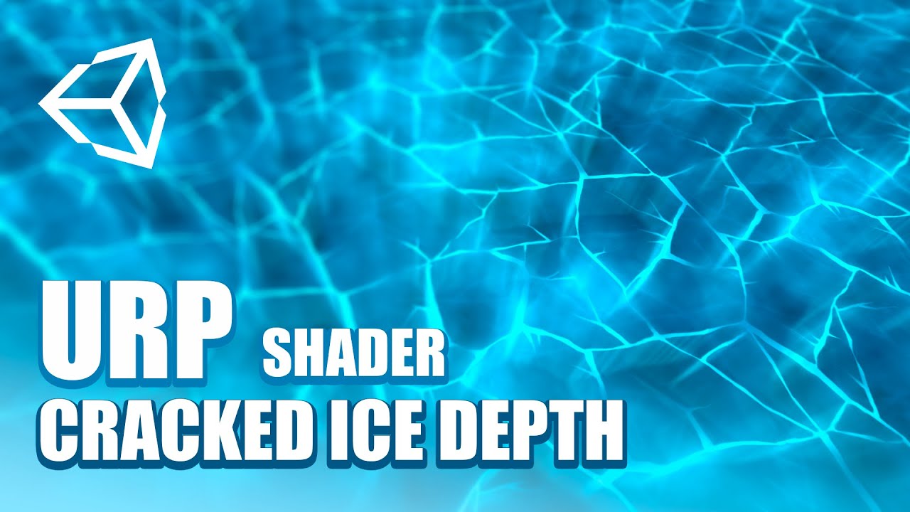
Que tal JetGuys ! Somos Jettelly y en este capítulo crearemos un efecto hielo quebrado en Unity, utilizando HLSL y Unity URP (shader unity, vfx unity).
📁Descarga los archivos del proyecto: https://www.patreon.com/posts/unity-shader-ice-44742647
Te invitamos a nuestro Discord en donde podrás compartir con más desarrolladores sobre VFX, Shaders ...
But there'S little other than googling like a maniac to find more
You can btw also look for Unreal-tutorials, since the logic in these shaders is quite similar. You will however have to adapt a little bit if the same nodes aren't available out of the box.
Glad you got it working.
I don't mind the ping, I have notifications enabled on the channel so will likely see it anyway if I'm online. It may be better to leave it out though as others might be able to help too if I'm not around.
Okay, will do!
This one might also be interesting, but I think he uses a couple of custom functions: https://www.youtube.com/watch?v=LKhGqKYOmbo&t=159s

This is a tutorial on using the Parallax Mapping in Unity Shader Graph
Checkout my new Floating Islands Asset:
https://bit.ly/lwrp-floating-insland
Checkout my assets if you want more Tuts!
LWRP Material Pack Vol 1: https://bit.ly/lwrp-materials
LWRP Material Pack Vol 2: https://bit.ly/lwrp-materials-2
LWRP Material Pack Vol 3: https://bit.ly/...
kk
One more question tho: How come I sometimes can and sometimes can't plug the output of one node into another node, even if their format seems to be identical (both for example being Vector3)?
It seems a bit like the tool is trying to tell me something but doesn't say it out loud in a rather passive aggressive way^^
There are some nodes that can't be connected to the Vertex shader stage ports. e.g. Sample Texture 2D can only be used in the fragment stage (all the other ports). Sample Texture 2D LOD needs to be used instead of for vertex ones.
So it's really just about which output they go to eventually?
Yeah, that should be the only reason why two nodes of the same data type won't connect.
I'm pretty positive there are built-in parallax mapping nodes now
Could someone explain how this happens and how to fix it? MAthematically I'm pretty sure it makes sense and it's probably easy enough to fix if you know how to, but I can't figure it out rn.
What I'm intending to do is using a normal map on a toon shader to add more surface detail, nothing particularly special, I guess, but the result there is kinda inverted, direction wise, and I don't think rotating the whole thing would really help me to any degree...

Nevermind, adding instead of multiplying seems to be the solution...
Normal map is defined in tangent space, so should be converted into world space if you want to dot product it with the world space light direction. Can use a Transform node to do that, Tangent -> World, Direction mode.
Well, that's assuming it's a proper normal map, not too sure looking at the preview
It's a normal map, setting the texture sample settings to Normals makes the hue go really blue for some reason.
is the texture's import settings set to normal map?
Nope it wasn't, but that didn't make any visible changes. However I do really like the effect I'm getting now, so no problem.
What is kind of a problem is that the shadow attenuation in the custom function doesn't seem to do its job... I am getting a solid white out of it, not exactly what I'd call a drop shadow^^''
does this error make sense to anyone? clicking on it bring me to the universal render pipeline script.

Hey shader n00b here. How might one go about making an unlit shader that inherits brightness/color from lights? Currently, too bright looks odd in the dark and vice versa. Basically the subject will be moving in and out of well-lit and shadowy locations and it should match the surroundings, but I don't know how I might execute that.
From looking into it this seems to be a genuinely difficult thing to accomplish
Would looking into particle shaders be the correct route?
You want an unlit shader that changes with lighting conditions...? Doesn't that just mean you want a lit shader?
having some very strange results here - not sure if this belongs in #archived-shaders or in #archived-hdrp
regardless, I am attempting to do what I know would be quite simple if I was just using raw OpenGL, so the struggles are perplexing, to say the least.
I want to use vertex colors, rather than textures - my understanding is that the particle shaders are the two shaders that support this. however, if I attempt to use the lit variant, rather than the unlit one, it falls apart, even in circumstances where a regular, non-vertex-color rendering shader works without issue. in this shot, for example, you can see the directional light, the correctly shaded object, and the failing shader in question - i have however, found a fix. (cont)

this setting lets me tweak it to look as intended - that said, i don't understand why it is functionining in this way

the asset in question looks like this when i tweak that HDR button

what I would like to learn is what is actually happening under the hood, and if the shader is at fault because I am using it wrong - i can't find any information about vertex coloration, since it is apparently quite uncommon to use it. advice?
i presume the answer is that I should be using a custom shader, but I don't actually know shader code, so i haven't had much success writing such a shader
(also, even now im pretty sure its not working correctly, it is partially transparent, or at the very least, blending with the background, seen here - the skybox is painting the color of the tower)

Idea ? #GUYS
@onyx veldt are you using shader graph?
no
ok, nvm then, I had a subgraph for parallaxing
unless you want it so you can rip the code out of it
@onyx veldt
https://pastebin.com/P1jnJSEJ so ive been trying to make this shader semi transparent but it didnt work out... anyone know where i went wrong?
Pastebin
Pastebin.com is the number one paste tool since 2002. Pastebin is a website where you can store text online for a set period of time.
Hey @patent goblet , in what way doesn't it work? what do you see versus what do you expect?
I see the shader specifies the transparent queue, is that also how the material is set up?
yup
I got a clip space question for ortho versus perspective - I understand both projections use different values for depth in the depth buffer, eg perspective is logarithmic and ortho is linear depth (between near and far planes). Is that also the case in clip space? or is the transformation made at some intermediate step?
to rephrase - if I have my world space -> clip space transform for ortho and perspective, and I multiple a world space vector, what value should I expect in the transformed z?
@patent goblet what are you testing that it blends with? an opaque object?
what do you mean by what object it blends with? i want to make the object itself transparent-ish
When you test to see if it is opaque or transparent, you must be rendering it in a scene with some other stuff - what is that other stuff? eg, render it next to a sphere with an opaque material
a copy of the same object with an opaque material
No, I want the entire mesh to receive the same amount of brightness. Like this:

Every spot on the subject relieves the same amount of light.
The way it's done in this image is to use volumes, but I'm wondering if this is possible to do with actual lighting
Hey guys any idea how to have a rounded rectangle mask that scales itself with the object? Right tnow the x and y part of the rounded corners are different because my quad is scaled in X.

I think you want something like 'nine slicing'
I can't use sprites tho :/
Is it possible to create a shader in PBR graph that has sand ripples on it as a 3D thing not just as a ripple texture on the shader?
why is my paint texture painting in pixels?

Need a recommendation on getting up tpo speed (quickly) with shader customization in Unity>
A quick search on Udemy turned up these
https://www.udemy.com/course/unity-shaders/
https://www.udemy.com/course/compute-shaders/
https://www.udemy.com/course/coding-in-unity-introduction-to-shaders/
https://www.udemy.com/course/learn-unity-shaders-from-scratch/
https://www.udemy.com/course/introduction-to-shaders-in-unity3d-with-shader-graph/
Any others? Any feedback appreciated.

Udemy
Learn to program the graphics pipeline in Unity for creating unique visual surfaces for game objects.


Udemy
Make your game look unique through image effects, shaders and custom lighting by learning Unity's ShaderLab language.

Udemy
A complete guide to Unity ShaderLab and the Cg Shading Language

Udemy
Shader Graph or: How I Learned to Stop Worrying and Create Stunning Visual Effects in Unity3D
I am trying to connect the node arrangement bellow into the Master node's normal input but it isn't letting me. I assume it has something to do with the coord space I am using, so I've tried setting all the node's Space enums to Object but that doesn't work. What is the correct way of doing this?

The DDX and DDY nodes cannot be used in the Vertex stage ports (Vertex Normal).
If you're using the PBR/Lit master it would need to be connected to the fragment one instead (labelled just "Normal"). It defaults to tangent space but you should be able to change that using the small cog on the master node
was wondering what that did. thanks o7
There is, here is a way to do it https://imgur.com/gallery/M2ZkPFE (ignore the preview the solution is on the site itself)
Hey guys i need some help, trying to do some basic reflections, so far it does a static reflection but not like how a mirror would work (when i move or look in another direction).

nice!!
perhaps lookup SDF shaders they are good for shapes
if you looking for mirror type of reflections (flat surface, water / floor) then you need to lookup planar reflections there are a few examples around. Basically it's using another camera to render the reflected direction, so hence is costly. While you can sacrifice quality for speed it will never be as cheap as a cubemap pre-baked reflections, which are ideal for non-flat complicated surfaces imo.
hey guys can anybody help me work out why my camera is having this kind of clipping effect when close to my water shader? image 1 is how it should look all the time and image 2 shows clipping

Guys,
Can you please help to understand the changes between 2020.1.1f1 version and latest 2020.2f7 ?
I just upgraded my project and colors changed.. please advise where to dig to revert the changes using newest version?
Please look on these screenshots before (dark) and after (a lot of blue).


What's wrong with this?
no one in their right mind is going to download that to look, use pastbin site or similar to show code

then just describe what is wrong / relevant error's etc. perhaps someone can assist
Thanks i think im gonna look into the urp boat project since i think they have that
Hey! I'm trying out the new hair shader. It has something called Light Facing Normal, which makes the normals of the mesh face the light at all times. But what light? The main directional light, like in URP? Or is it somehow facing all the lights?
Also, is this a feature that exists in other engines, say Unreal, if I'd want to recreate the shader there?

Attempting to use a Triplanar node in a graph utilizing webcam input.
Is it simply a matter of replacing the existing UV node? I've been searching for examples using Triplanar but haven't found any.
Other than stipulating use in Fragment shader stage the documentation doesn't help. https://docs.unity3d.com/Packages/com.unity.shadergraph@10.3/manual/Triplanar-Node.html

Use the triplanar node instead of the Sample Texture 2D node. Just plug your texture in the triplanar and you're good
Trying to clip part of an object based on position by computing the dot product, but this doesn't seem to do anything. Can anyone explain why?

The value of the Alpha Clip Threshold needs to be larger than the Alpha to clip the pixel. You should be able to use something like this :

hello , i want share an uv map for multiples GameObject

i do this but its a little weird
so i figure out , the issue is the uv rotation
so i solve this
now its like this

its my shader

the top is for turning the gameObject
and the bottom is for resize the uv for each cube i have
but i have some cube with bad color
if you look, the green should not be there
Some one can explain why ?
I think it because of the Tile variable
but i dont know why ^^
help me to figure out please
Or just explain me how the flipbook node work
but please help haha
Someone can explain me the tile Input
The Flipbook nodes selects a portion of the UVs. I think it's mainly intended for things like sprite sheets, where you store multiple frames of a animation in each tile of a texture and use the flipbook to play through that animation by increasing the Tile input.

hi! sorry for asking such a trivial question but I've been struggling with this all the morning >__<' I am creating an unlit sprite shader, and I want to create a nice color gradient, but I can't figure out how to know the position of the pixel that is currently being rendered D: I've tried everything T_T, in this case, I'll get this error: undeclared identifier 'screenPos' at line 895, so I guess I can't use screenPos there... but then, how? plz halp @.@

Yeah... But that can help me to make a animated floor in a grid based game

I can make that if i want
but its broke at some part
This is code generated from a shader graph right? Is there a reason why you aren't handling it in the graph? If the SurfaceDescriptionInputs struct contains the screen position, you might be able to use float2 screenPos = IN.ScreenPosition.xy / IN.ScreenPosition.w; to declare that.
thanks for the help! but I got this error now invalid subscript 'ScreenPosition' at line 895 it seems like SurfaceDescriptionInputs doesn't have that info... I tried using the graph and I managed to get the gradient with this 4 bad boys... but then I wanted to input a different gradient color for the bottom, and another different gradient color for the top (it's hard to explain... but basically I want to be able to make a sky in which, when it's 6AM, it dawns with a red->orange color, but in the top blueish... and then it switches to full blue)

so I switched to code to have a better control... but I can't find the documentation of SurfaceDescriptionInputs ^^' and I found several ways on accessing the position of the pixel, but none of those work... probably because I am writing my code on SurfaceDescription and not on "frag"... but, as you can see, I am totally lost by now hahaha
oh sorry, didn't answer the first question... yeah, it's generated from this one

Right okay. I'm finding it a little strange to use the Position node here, and by taking the yellow (3) output and putting it into the Time (1) input it's truncating the vector value, which means it's only taking the X axis into account here. I'm not sure if that's what you intended or not, but a Split node could be obtained to get a different axis. G being the vertical part.
Personally with sprites I'd suggest using the UVs / texture coordinates instead, unless you're using multiple sprites for this sky perhaps?
Again they can be split to obtain each axis. (only R and G is really used). If you just need a two-colour gradient, you could also use a Lerp node to interpolate between two colours, e.g.

If you changed those Color nodes for properties you could also control them from a C# script to animate the day-night cycle
omg, that's awesome... and for the gradient on the bottom, I could use that SampleGradient node... I didn't know about that Split node hahaha thanks a million times! I am going to try to implement it that way
yeah! that's exactly what I want... thanks a lot, you saved me hahaha, I am gonna try that now
it worked like a charm, thanks a lot! one more thing... do you know how to get this properties from script? I read on the forums that you have to write Vector1_1efaa5c...... is there a way to write it just like Daytime?

You can change the reference that's used in the Node Settings tab of the Graph Inspector window (toggled with button in top right of the graph). The settings for the property will appear when it's selected in the graph or blackboard window.
thanks a lot! my code looks cleaner now
Is it possible to get the average color of a texture using a shader, and expose it as a read only property to unity scripts?
Hrm, this looks promising https://www.reddit.com/r/Unity3D/comments/6i2sby/vertfrag_shader_taking_the_average_color_of_a/
reddit
4 votes and 13 comments so far on Reddit
This shader shows up as the bright pink "Error Shader" whenever I use, does anyone know why?

Can I have a hdrp/lit and PBR graph at the same time, I'm trying to make a materialized texture shader, but I don't know where I can change the transparency of the shader
I'm trying to get Shader Graph to work in VFX Graph as a Lit Particle, but I keep getting this error. But ever sense they changed Shader Graph the Lit VFX Master node no longer exists, so I assume it has to deal with switching it to Lit in the material type in Graph inspector. But I can't seem to get it to work.

I am using stencil in shaders to draw a road on top of a terrain but now I have this issue :
A road behind a hill will be drawn on top of (i.e. show through) the hill.
How to prevent that ? 🤔

Haven't used VFX but yeah, I'd assume that needs to be set to Lit if you're using the Lit Quad output. Make sure you've saved the Shader Graph with the Save Asset button in the top left. The error message also might just be old, it likely won't disappear unless you clear the console.
Ahh yeah hitting save made it work 🙂 Ty 😄
Hmm. I wonder why they removed distortion from Shader Graph for VFX Graph. I used it in the past, hmmm.
Even as a regular HDRP Shader it's just grayed out. Can't click and drag to create a node for it, etc.

Might be an option in the Graph Inspector window (graph settings) to enable it?
Oh, and I don't think Shader Graph had distortion for VFX Graph. VFX Graph just has an Output Distortion block that you might have used previously.
Is it possible to put noise texture and height texture into pbr graph
and make the shader look more realistic
Let me do some research .... If there is a block I can't find it, going to research it 🙂
FOUND IT
Heightmaps use parallax mapping, which offsets the UV coordinates. If you're in Shader Graph v10.1+ there's a Parallax Mapping node. Whenever you use a Sample Texture 2D you'd use the UVs from that node.
Or there's Parallax Occlusion Mapping which is more expensive.
You can also sample noise textures but it's up to you how you combine it into the other inputs like albedo/base colour, metallic, smoothness etc.

Thank you
can anyone give me some direction on how I'd change a custom shader from blended alpha to cutout/clip alpha?
The character's hair shouldn't be translucent, just opaque with some regions of clipped transparency

The code isn't crazy long, but I still can't really decipher what I should be changing -- I've looked around on the internet for the last hour or so but I can't figure it out

I've messed around with alpha:fade changing it to alphatest:something but Unity's documentation isn't exactly clear on what exactly goes after the colon
Well, to be more precise, I don't really know how to do what Unity suggests I do, haha
Guys, i have a simple waves shader that moves vertex (made in Shader Graph, i'm quite new to shaders actually). Now, i have a C# script that needs to know the y position of the wave at a certain world position. Is there any way to do that?
How do I fix this?

When you have a solution or overall something to say to me the @ me
@regal stag I've been bookmarking your tutorials because I read the "Intro to Shaders" one and thought it was well written, and Shaders are the next thing I plan to start learning in the near future. But, I'm just noticing most of your posts are tagged URP. Are they still going to be applicable to me if I'm using HDRP?
Any way I can copy a nearby already altered pixels values into the current one in the shader? I don't think just tex2D _MainTex works?
maybe i can pass it to the next pixel via property? 🤔
They should still be useful but some things may need changing slightly for HDRP. Shader Graph has a few differences in HDRP, like the View Direction node is normalised automatically, and World space is relative to the camera position (https://docs.unity3d.com/Packages/com.unity.render-pipelines.high-definition@10.3/manual/Camera-Relative-Rendering.html). Any custom lighting functions I use won't work in HDRP too.
Ok, so it sounds like they'll mostly be applicable.
I'm particularly interested in the force field one because I have a character that uses one 🙂
Improved on my previous attempt https://i.imgur.com/gtIAU7K.mp4

guys why is the height map not really showing? it's just creating an illusion within the object

A height map here will fake the depth by offseting the UVs (search for parallax offset mapping).
if you want a real displacement, you will need to use vertex displacement and probably also tesselation.
I'm making a map mesh generator that won't need elevation for the gameplay. So the ground is just a flat grid. But I do need to render bodies of water so they look nice.
I'm a total noob when it comes to shaders, is it possible to make a flat mesh look like pretty lakes with shaders ? Specifically to make it look like it has depth, with coasts going down and disappearing in water and waves hitting the coast.
Or will it be easier to just generate mesh that has "seabeds" ?
It's possible with a flat plane an purely in shader, but it will be way easier with a "ground" mesh + water plane.
thank you 👍
thank you so much brother
I want to recreate this in shader graph. Does anybody know any tutorial on triplanar mapping in urp?https://threadreaderapp.com/thread/1113100182655262721.html

Thread by @adamgryu: "I've been asked about how some of the effects in A Short Hike were achieved, and I thought I'd share some resources in ll :) Firstly, I wouldn't have been able to make the terrain without triplanar m […]" #unitytips #gamedev #unity3d
@fallen cypress wait can you convert shaders?
es
yes
but idk how the manual tool doesn't work it's not compilcated shadrt it won't take time
@fallen cypress do you know how I can create a urp shader?
you mean shadergaph ?
no the custom ones
shadergraph can generate shader which is basically the standard shaders ( HSLS) idk if unity cg is compatible or not but some people convert it easily , i'm not pro at shaders but some basic stuff
I think the automatic upgrading doesn't work sometomes because some snippet of the codes use unity.cg light model but you can replace it
Unity is the ultimate game development platform. Use Unity to build high-quality 3D and 2D games, deploy them across mobile, desktop, VR/AR, consoles or the Web, and connect with loyal and enthusiastic players and customers.
i'm trying this but it doesn't work
The automatic converting only works on upgrading unity's built in materials/shaders. e.g. the Standard shader to the URP/Lit shader. It doesn't convert custom shaders.
Triplanar mapping has its own node in shadergraph : https://docs.unity3d.com/Packages/com.unity.shadergraph@10.3/manual/Triplanar-Node.html
I just want this Silhouette-Outlined shader lul
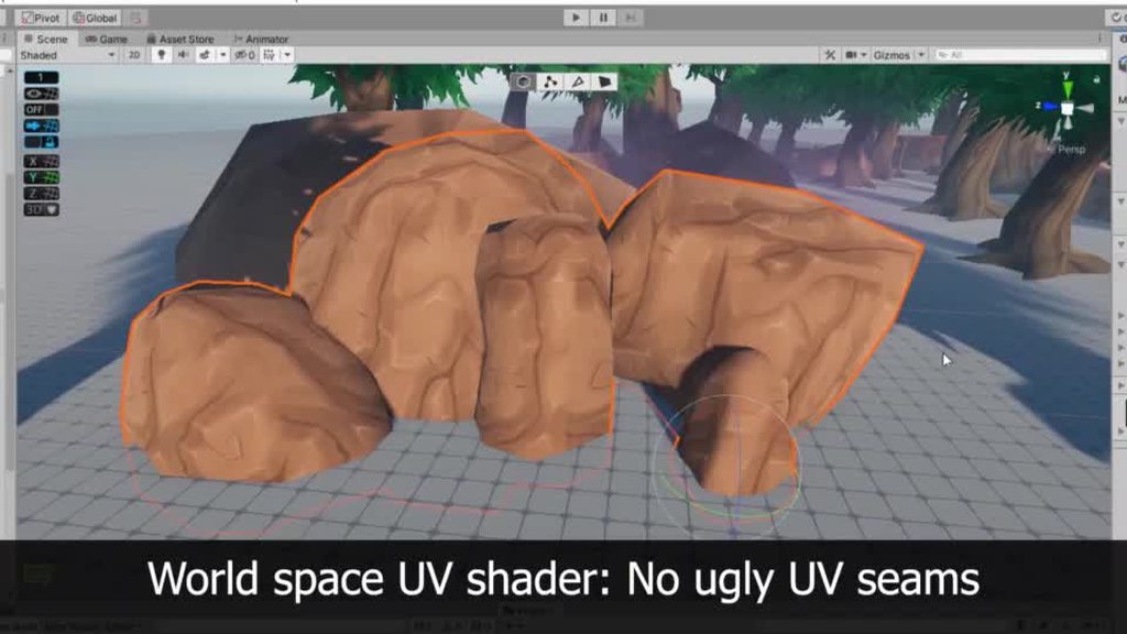
I've also got a tutorial page on triplanar mapping here : https://cyangamedev.wordpress.com/2020/01/28/worldspace-uvs-triplanar-mapping/
Might be more useful if you need to specific different textures for each axis. I think Remy also has a node library that includes something like that if I remember correctly.
I also have a triplanar "framework" in my node library, allowing you to optimize a bit the sampling of multiple textures : https://github.com/RemyUnity/sg-node-library/blob/master/Documentation~/images/nodes/triplanar/sample.png

GitHub
Node library for ShaderGraph. Contribute to RemyUnity/sg-node-library development by creating an account on GitHub.
I followed a tutorial and ended up with this

the bad thing is that is looks like shit

@amber saffron will try it
I have some nodes that might help you here, like a "triplanar sample top / side" where you provide a top texture, and a side one, and boom, works.
I am using stencils in shaders to prevent terrain from poking through roads, but now I have this issue :
A road behind a hill will be drawn on top of (i.e. show through) the hill.
How to prevent that ? 🤔
Can I make a terrain material using shader graph

Is it impossible to make a toon shader with only a PBR graph and textures?
very possible, there are many examples about. Deciding on style is the hardest part 😉
as there are many different ways to approach this from artwork pipeline to lighting
Ok, cool. I was just asking because last time I tried to create a toon shader, it either got too complicated or broke the default HDRP pipeline, so I could only see some errors in the console and a gray screen in the scene
ah well HDRP is a bit more limiting, as in you can't really tweak the lighting / shadow aspect.
For HDRP I would be more looking at making my artwork and asset pipeline give the style, not the shaders.
but that's not to say there are not things which can be done
🤔 I more think of URP when considering toon type of styling, HDRP lends itself to be more photorealistic
So you can only go with one style in the game, and there's no unity version that has both pipelines available in a single project
while there is some steps towards making it easier to have a project which could use both, practically the two are still miles apart. espeically when it comes to lighting and setting up of the scene.
I suspect it would be a lot of work to do both, but if you have a capable team go for it. However I would try to make the core of the game work in one before looking to develop the other.
got it, I'll try the toon in the future then, when I have finished my first project
@fickle obsidian Toon and HDRP can live together : https://www.youtube.com/watch?v=WAIqvnaV3uI

This is the improved one and rendered at 8k UHD at 24 FPS.
The whole scene or project is in HDRP - DXR/Ray Tracing mode.
The environment and the character uses RealToon HDRP.
All are real time, not bake.
This is fully Ray Traced GI, Shadow and Reflection at Quality mode.
The character and some objects on the scene uses the upcoming Screen Spac...
I made this water shader in shader graph


It has procedural refractions
you can edit every property of the shader within the material
and each setting is per material
so you can use it for any liquid without editing the actual shader

It runs on the universal render pipeline
how should i make the white dot more transparent without the background turning wierdly red like the subtract thing i tried earlier

i wanna make it more see through
please help
Subtracting would cause values to go below 0 which will likely cause problems with blending. You could use a Saturate node to clamp it between 0 and 1. Or use a Multiply node instead of subtract.

Split
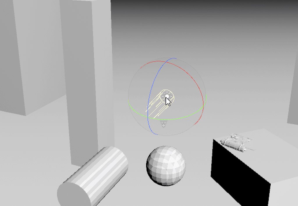
so i have this basic node setup for trying to recreate the transform gizmo -- essentially when looking directly it becomes transparent.
it works to some extent, only in one direction of the axis (so for x axis, it will only work when looking in direction X, not (negative) -X)

I'd use a Dot for this. Get the X direction of the object by transforming the vector (1, 0, 0) from object to world space, get the dot product of that and the direction from the camera to the object, get the Absolute value of that, One Minus to invert it and use that as the alpha.
sorry back -- took a lil break and remembered came across a similar issue in my program, so i take the same val and clamp it to get a -1 or 1,
then multiply that back in

came across a bit of an issue -- how would i get that alpha data and pass it into c#?
lets say i dont want my gizmo to be intractable below 0.25 alpha val. .
I heard using setfloat() is slow. Is that true?
Like if I want a value to change should I not do it through script and instead use sine waves?
I think this is where I should be with help.
I'm using free tecture packer.

This is what my texture project looks like.

These are the settings.
My unity project is in 2D, but there's no 2D option.

The marbles spawn in with a few missing in empty cells, and when they do spawn they have all this digital chaff around them.
Any idea on how to fix this?

The animation sheet comes in like this on unity.
I have a working Shader Lab .shader file.
Is there some way to make this complete shader available inside ShaderGraph?
I've looked at the documentation for the Custom Function node but still not sure if this would be the right solution.
https://docs.unity3d.com/Packages/com.unity.shadergraph@6.7/manual/Custom-Function-Node.html
I'll be back after dinner, @ me.
You would just get it from the material. also small tip, you can use the One Minus node instead of a subtract with 1 in the A input.
ah thx -- also i did try getting it from the material, but that seems to return the alpha val i set to the color property, which doesnt correlate to any changes made by the shader
(my other option would be to try and perform the same calculations as the shader in a c# script, and pass the alpha val into a dumb shader -- that way i can retain the end copy on the cpu
from my research, it is possible to transfer data back to the cpu, but its quiet slow. . for what ever thats worth)
have you tried setting the material as addressable?
oh, how would i do that?
wait hold on
also just checking but did you try material.color? Also if you didn't know, you can rename the color property to something easier to remember in the blackboard or property inspector depending on the version of sg you are using
material.color gave me an error unfortunately. .
as for renaming, i pulled the code generated by shader graph and tweaked the ztest off so its always on top, wouldnt want a transform gizmo that gets covered up by other objects - so i didnt bother renaming it incase it messes something else up ;-; (only realised after the generated name was indeed a tad weird to remember)
Am I in the right channel for my issue?
I think that's because material.color expects the property name _Color. Wait
By default, Unity considers a color with the property name name "_Color" to be the main color. Use the [MainColor] ShaderLab Properties attribute to make Unity consider a color with a different property name to be the main color.
This is the same as calling GetColor or SetColor with the property name of the main color as a parameter.
ah i see, adding [MainColor] to the name would let unity think its the main color. .
it's just semantics since it does the same as GetColor and SetColor but useful to know
mhm,
well, no idea if it works -- that should do everything the shader graph did as c# code welp -- guess theres only one way to find out. . .
thx for the help! everything seems to be working as i had wanted with the c# variant of the script, (realised I can use maths.sign instead of clamp)

I heard using setfloat() is slow. Is that true?
Like if I want a value to change should I not do it through script and instead use sine waves?
This Z-test used to work until I updated to URP 10.2.2. It doesn't seem to do anything anymore. Does anyone know why?

@mental lake you're using a camera with depth enabled?
Yeah depth is enabled
this might be a bit of a stretch, but doesn't anyone know of a Triplanar shader which supports vertex color height blending
Any good free shaders/examples? I want to have some example shaders for realistic graphics and limited hardware.
How I can write custom shader for Terrain and still have texture painting functionality?
I managed to create Holes, but I dont understand how layers work. I created simple nodes to handle 4 layers, but how introduce more?

I have only _Splat0, to _Splat3 available.
So I dont understand how I can add 5 layer.
Can somebody help me how to make my 3d materials not stretch when I scale the object?
That would be possible only with world space projection. Or you'd have to compensate UV detecting specific direction.
@light belfry The thing is: "what does it mean to not stretch?" For a cube with a repeating texture, I can think of an answer. But a textured sphere, like an earth globe, what does 'not stretching' mean?
yes I want to make a repeating texture
For cubes, or things that roughly look like a cube, you could look up a tutorial on triplanar mapping/projection in Unity
ok thank you @turbid holly
Quick question, is the best way to reference a shader graph shader to turn it into code and use shader reference?
Or just use Shader.Find
Does anyone know how to fix the inside of the object with the shader being opaque

it's a double sided transparent shader
in shader graph
URP
You are using Fresnel Effect right? It returns 1 as those faces have normals facing away from the view dir. You can use a Is Front Face node a Branch to set the values to 0 for back faces to fix that.
how can i partially scale a range ?
for example

that left portion i want to change its value so it would go like 0 to 0.8 and because its already tiled it would go [ 0 -> 0.8 ] towards 50% ( since its 2x tiled ) and from 50% to 100% it would go zero to 0.8 again
any ideas ?

✔️ Works in 2020.1 ➕ 2020.2 🩹 Fixes for 2020.2:
► When you create a shader graph, set the material setting in the graph inspector to "Lit"
► "Albedo" has been renamed "base color" in the master stack
► Editing properties must be done in the graph inspector instead of the blackboard
Grass rendering is a challenging problem in many games. One way...
I want to follow the tutorial but for HDRP. But Instead of placing it randomly, I want to place it randomly on a splat map. Do you know how this could be accomplished?
Hey everyone. I've got a lot of sprites drawn on very simple 2-triangle planes that I generate procedurally to the dimensions of the sprite and reuse wherever possible (so multiple instances of the same sprite use the same once-generated mesh). I'd like to dynamically recolor these sprites using a shader and a mask texture, say for team colors. So far I have two options:
-
I can set vertex colors on the generated meshes, which are then read by the material rendering the sprite on the plane. This means less mesh reuse, especially with lots of different recoloring options, but the material properties are unchanged when setting the pass.
-
I can set a MaterialPropertyBlock for the material with the picked colors I want (red helmet, blue shield, etc.) on that particular sprite, and all of those like it.
Anyone have any thoughts on which of the two would be better and more performant? Any advice if I go down one route or the other? If it matters, this is with the #archived-dots HybridRenderer, which is also why I'm not using much of Unity's 2d tools.
It works but it doesn't show the edge on the other side of the circle

Do the branch straight after the Fresnel Effect, before combining the depth-related part. e.g. https://www.cyanilux.com/tutorials/forcefield-shader-breakdown-simple/
anyone has an idea how i can find out if the normal of an direction faces directly to the camera ? i think it's the dot product but how do i get the camera direction vector?
oh maybe i just found, float3 viewDir = UNITY_MATRIX_IT_MV[2].xyz; , trying
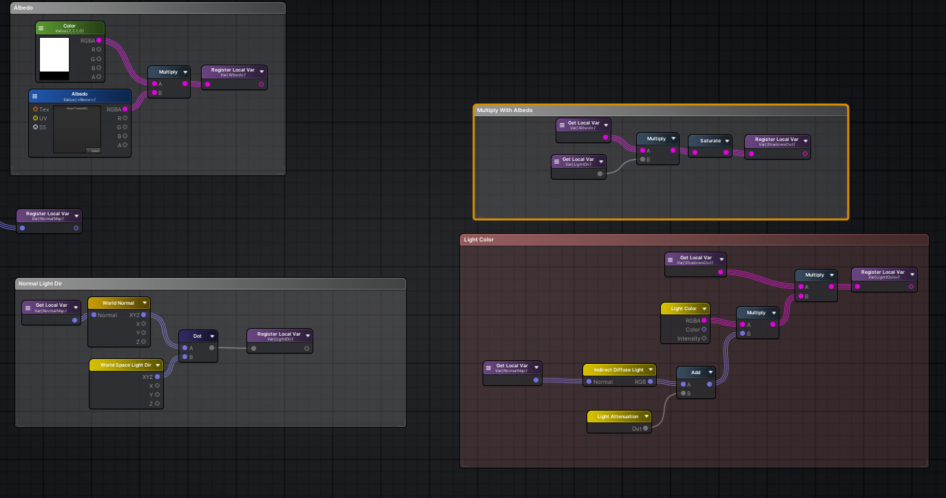
Alright are there any shader gurus on that could perhaps help me out in solving something?
I am challenging myself to make a pixelated custom lighting shader, such that lights attenuate in a pixelated style like this:

I have the basic custom lighting shader set up, but I have no idea how I would approach this
I've done tons of research and there seems to not be very much documentation on this specific problem
The image I posted above is faked using a light cookie, but the thread I found it in said it should be more than possible to create this with a shader
I also did find something similar on Twitter here:

Pixelized dynamic lighting. #pixelart #lowpoly #b3d https://t.co/5KC2cfanuP
Likes
421
I did notice the "pixels" distorting at weird angles in this example, but regardless it's still a really cool effect
I'd love to try and figure it out if anyone wouldn't mind giving me some pointers

And here's another example from the same person
Most custom lighting shaders just seem to be generic toon shaders but I want to try my hands at something more complicated
@grand jolt I'm trying to make sense of what space those pixels are in in those gifs. They seem weirdly both UV and screen space.
The buoy one kind of throws me for a loop
tbh I'd be fine even getting the first pic I sent
I'm not sure what I should be trying to mess with, my first thought would be the lighting attenuation
but it seems like all my results of messing around with it have just yielding either changing its color or falloff intensity
I also use Amplify to create my shaders but the logic would still be the same
guys ... what do i have to do to pass an float variable from geometry to frag in urp?
@grand jolt I don't know if this applies to other pipelines, but in URP one way might be to round the position used for calculating light attenuation. This works best on surfaces aligned to the world axis. In Shader Graph would be this :
(using AdditionalLights function from https://blogs.unity3d.com/2019/07/31/custom-lighting-in-shader-graph-expanding-your-graphs-in-2019/)

Hold on lemme check it out
ohh huh
okay I'm going to need a bit
That additional lights is a custom function right?
Amplify doesn't seem to have anything like that to my knowledge
Yeah, it was taken directly from the article
I think amplify has "custom expression" or something. That function code will only function in URP though.
Oh really?
hmm
Why would this not work in other pipelines?
I'm on LWRP pretty sure
I forget how to check
But I know I am not on HDRP and SRP
Should be able to check which pipeline you're on via Edit > Project Settings
Under the Graphics tab
If you're on LWRP that should be fine too. LWRP was renamed to URP, they are the same
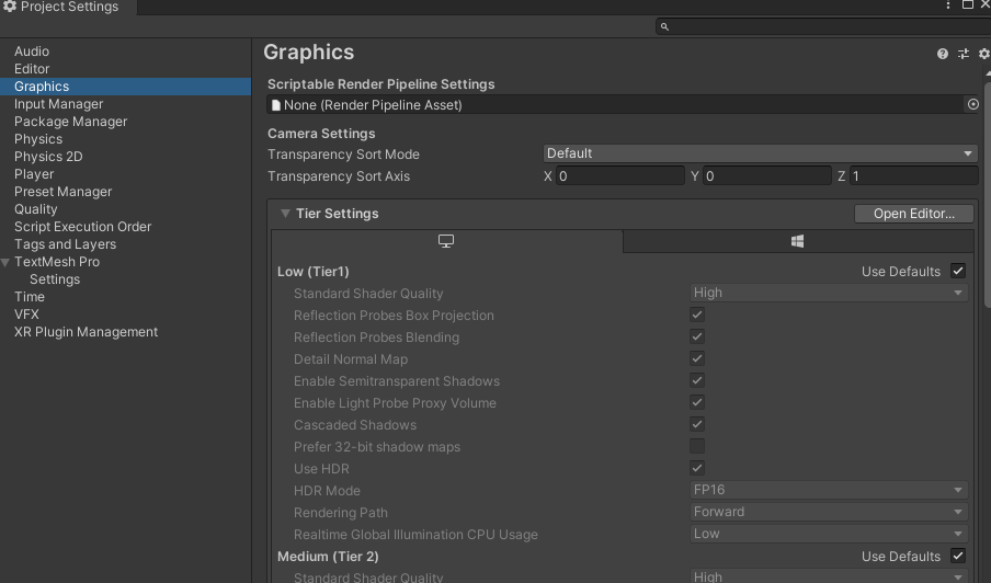
If no asset is assigned, it should be the Built-in RP
Is that not URP?
or is it the same thing
Sorry there's so many pipelines and I keep getting them mixed up
No, Built-in RP is like what Unity was before the additional pipelines was introduced. LWRP/URP is different.
Oh damn
I still feel like I should be able to replicate this with Amplify
don't know why I wouldn't be able to
This is the gist of the shader so far
very basic

I'm wondering if I'd just replace the Light Attenuation node with the logic you posted earlier
Oh wait
no
hold on
Let me try something
Hmm I imagine you'd have to replicate what the light attenuation node does... I'm not too sure on the exact function used though
Yeah there's no documentation on it
Looks like it's just the thing that calculates the NdotL lambert lighting
And also the distance and shadow falloff
Any shadergraph users find that double clicking the .shadergraph files sometimes doesn't open the shader editor? The only solution I've found was to use Package Manage t completely uninstall both URP and Shadergraph, then reinstall both. PITA!
Just for testing's sake
i tried swapping this out
So normally it looks like this
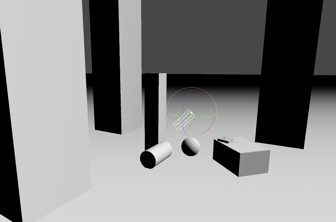
with that swap
it goes to this
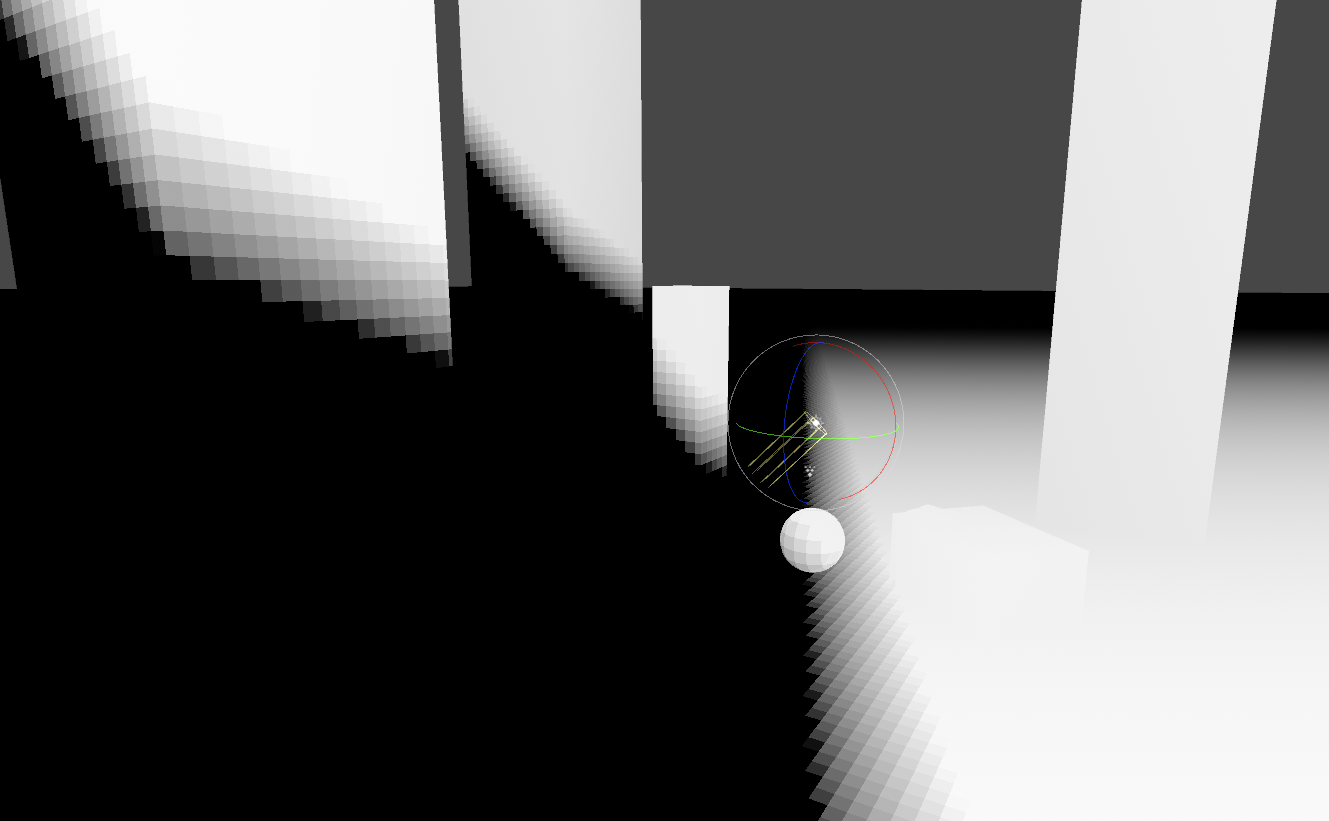
Which is kind of the pixelated look i want but obviously its not fully correct
Directional lights don't use the object's position at all
It's the dot product of the light direction and the normal of the object
Ohh
I guess you could try rounding the normal direction, but I don't know if that will give you square pixels
interesting
lets see if my gif loads
I can't tell if this is correct or not lol
There's some weird banding
You do have the exact same banding in your image too though
hmm
You'd pass the variable out of the geometry shader output struct / fragment input, through one of the TEXCOORD channels.
I don't think I've ever encountered something like that. Maybe it's a bug with the specific version of Unity/URP?
Yeah, my idea was for point lights not really the directional one and only really works for objects aligned to the worldspace axis so doesn't look great on curved surfaces like the sphere.
I was thinking you could round some triplanar UVs maybe
Ohhh
Pixelized dynamic lighting. #pixelart #lowpoly #b3d https://t.co/5KC2cfanuP
Likes
421
Look at the way it kind of bends
would that be some sort of triplanar shenanigans?

Triplanar wouldn't really bend, I don't know how Lettier is doing their effect
Actually, I think Lettier might just be doing the rounding thing on the normal vector
The normal vector?

That looks familiar
What does it looks like on a sphere or cylinder?
Also thank you for helping me out
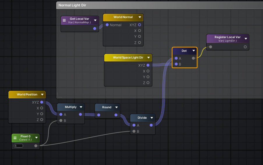
This is the graph, It's the N Dot L that's used for directional lighting but the normal vector is rounded, similar to before

It should work. It's the same logic for point lights, except the direction is the direction from the light to the fragment position and you also apply a distance falloff
Though I'm not sure if you can round the distance falloff in exactly the same way
It looks like just a bunch of random numbers
It's the light dir, I just hardcoded it sorry
Just easier to test with numbers in the graph 😛
So i

Isnt this the same?
(my world space light dir is normalized, its an option in the node)
Looks the same yeah
The cube mesh I was using also has smoothed normals which seems to be a requirement for this method
ohh
that would make a huge difference
Should polygonal density affect the amount of pixels you see on the shader?
Don't think so, just the normals are important
Alright
Okay so in that case, all I need to figure out is how to get this working with point lights
what I've tried so far hasn't worked
I'd just have to recreate the light attenuation node manually and round it as well correct?
Well idk, this rounded N Dot L might work for point lights too. As MentallyStable mentioned they use it too, it's just the light direction is based on the fragment position too.
But it will be harder to pixelate the distance attenuation. That just uses position, not normal. Rounding that won't lead to the same pixels in the same place
So you'd get faintly overlapping pixels in different spaces
Which would probably look offputting
But you might not have to
Hmm yeah, maybe it would look okay without the distance attenuation rounded
And just the normal rounded part
So how do you calculate light attenuation normal if I weren't to do any of this rounding stuff?
Is it world normal • world space light pos?
No, world normal • direction from light pos to fragment pos
Uhh hmm
(fragment pos - light pos) normalized
Lemme google how to actually calculate the second part of that in amplify
because theres no fragment pos in amplify
It's probably just called Position, same as Shader Graph
world position?
Yes
Hmm, this is what it looks like with a point light

Is the ground plane using the same shader?
cause shouldnt there be a pixelated fall off
The normals are all the same on the ground, and since you're only pixelating that, they end up the same color
oh jeez
And so you're only seeing the distance falloff, which we intentionally didn't pixelate
And as you mentioned, pixellating the distance atten leads to overlapping because they aren't the same

Oh yeah that's really jarring
What if you pixelate the distance fall off and not the other?
What kind of result does that give you?
Perhaps having a regular directional light but having the pixelated attenuation might stylistically look nice
That's what I began with earlier

Hmm i see
Wow this is difficult
If you wanted it to actually look proper would you just have to use cookies?
I was wondering if you could apply some of the tricks used for the stable dithering patterns in Return of the Obra Dinn, but use a pixelated pattern instead of a dithering pattern.
https://forums.tigsource.com/index.php?topic=40832.msg1363742#msg1363742
Return of the Obra Dinn [Releasing Oct 18]
@grand jolt Does the light cookie approach work for directional lights?
Haven't tested yet
I'd imagine you wouldn't get nice pixels on the sides of objects
The projection would stretch
but I got it looking correct with spot lights
For point lights, I couldnt figure out how to properly make the cookie
sec
Imagine this, but with a more grid-like pixel pattern

The scene without the dithering looks like this

Yea that makes sense
Yeah I can't get the cookie to actually make it look right for point lights
Cause I can't actually control the attenuation with a cookie
A cookie is basically just a mask

this is me just using a soft circle set to 32x32 with point filtering
Hmm this is kind of challenging
wrong chat lmao
Hey @regal stag is it alright if I DM you?
Or @low lichen if you are available too
Apparently this is a common issue but I cannot for the life of me use the attenuation formula without getting massive squares
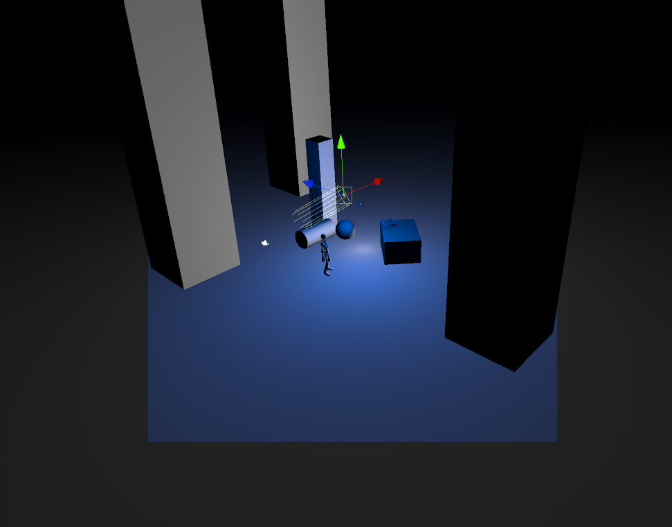
It's driving me crazy .-.
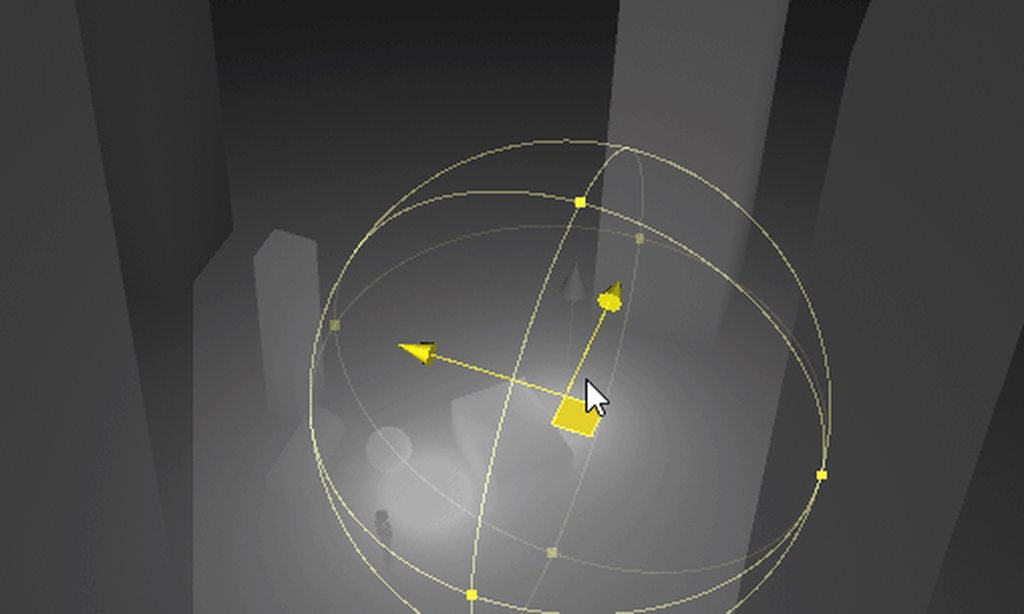

this is all i am doing btw
If anyone knows or could help me out, it would be massive appreciated
simple question maybe
But why doesn't my shader graph have a blackboard?
I can't rename any of the nodes
Oh, never mind.
I reloaded the graph and it appeared
Anyone know how to get lighting data for a 2D shader graph?
Hey, does anyone know if there's a vertex shader version of the standard URP shader somewhere?
Is there any reason why the URP lit shader master stack would have the alpha node missing? I can manually add it and connect a node to it but it has no effect and is grayed out
ProBuilder has one
In its URP examples/additional Assets
Forget what it's called. There's some button in ProBuilder to import it
Hey, so, tell me if this is horrible or good, I really can't decide
I made a water shader that is entirely tileable, injecting the position into the voronoi UV's

The desired effect is perfect
However, I don't know if I can do anything else with this

I feel like it's magic that this even works
It totally falls apart when you actually rotate the object
But otherwise, it looks perfect

if you use world space xz position for the UV it should do all that and work for rotations too
How would I extract just X and Z from the position node?
send it to a split node
welcome 👍
what's the equivalent of WorldSpaceViewDir() for URP?
GetWorldSpaceViewDir(positionWS), from https://github.com/Unity-Technologies/Graphics/blob/master/com.unity.render-pipelines.universal/ShaderLibrary/ShaderVariablesFunctions.hlsl
The graph settings (tab in Graph Inpsector window, toggled with button in top right), is not configured as Transparent or using Alpha Clipping. So the alpha is greyed out as it is unused.
i keep getting undeclared identifier when i use getworldviewdir
While reloading may have made it appear, there is also buttons in the top right of the graph for toggling the Blackboard, Main Preview, and in v10+ Graph Inspector, windows.
It's GetWorldSpaceViewDir, not getworldviewdir. Make sure you are passing in the world space position as a parameter. If it's still undeclared, you probably aren't including the URP ShaderLibrary files. e.g. #include "Packages/com.unity.render-pipelines.universal/ShaderLibrary/Core.hlsl" should also include the ShaderVariablesFunctions file that contains that function.
something has to be bugged cause it's not working
is it bcus my shader library doesn't contain shadervariablesfuntion.hlsl?

Maybe the function didn't exist in the version you're using
Try just GetCameraPositionWS() - positionWS

Okay... _WorldSpaceCameraPos - positionWS then
without paramerters

oh wait
i changed my out.view to a float 3 and_WorldSpaceCameraPos - positionWS
worked
thank you
where were those variables located
_WorldSpaceCameraPos is one of unity's built-in shader variables. In URP it's defined in https://github.com/Unity-Technologies/Graphics/blob/master/com.unity.render-pipelines.universal/ShaderLibrary/UnityInput.hlsl (included automatically when Core.hlsl is included)
GetCameraPositionWS() is in the ShaderVariablesFunctions.hlsl now, but prior to v10 it was in Core.hlsl. It just returns _WorldSpaceCameraPos though currently.
You can switch the branch/tag on the github to view a specific version
Looking at the code used by the Lit.shader is usually a good place to start looking when you need something though. e.g. https://github.com/Unity-Technologies/Graphics/blob/master/com.unity.render-pipelines.universal/Shaders/LitForwardPass.hlsl
ok thank u
@regal stag i think your way of getting view direction is buggy
do you know any other way to get view direction cause my specular is all messed up
It's how view dir is calculated so I don't see why it would be buggy, unless your using an orthographic camera. If you're using the view dir for calculations you might also want to make sure it's normalized.
there is a safenormalize function I believe as my code uses this at top V = SafeNormalize(V); //WorldView
also may want to ensure normals are normalized too
yup, the specular spot stayed in the middle if I didn'tnormalize thank you

If it's from a texture, add an other sampler with the offseted uvs.
You can stack simple transparent shaders. But using the scene color node (for your distortion effect) make it's impossible, as the scene color is a buffer of all the opaque objects on screen.
Interesting... so distortion effects are going to be severely limited since that buffer can only really be used once without causing artifacts like seen in the vid
Thank you! I thought it had something to do with that, I had accidentally disabled that tab. Your recent blog post has been super helpful for getting started with shader graph, btw 😎
its a full texture with alpha applied
i just wanna move it sideways
but i dont have a texture
its a render texture with added dirt texture
re-sample the same texture with offseted uvs, and only use the alpha from there
guys little help please.

why my texture is black ?
else main preview it's done ?
when i multiply with MainColor he failed look
i remove it

he is working
but i need to multiply it with mainColor
Is main color black by any accident ?

And on the material ?

here when i don't use MainColor
And on the material ?
OH
By default it's black
right right !
Yeah +1 done my boys
btw remy what is punctual shadow filter ?
if you know
Where did you see that ? But from the name, it's the filtering settings for point light shadows (you know, hard/soft ...)
I'm going crazy here. I've got this shader to "clip" parts of an object that have already crossed the plane. Somehow, this is currently dependant on where I'm viewing it from ???
The object is visible if I'm (the camera) behind the plane, whereas its not visible when the camera is in front?
I have no code dependant on the camera, the section point and plane is just the normal of the plane and the plane position. So I come to the conclusion that something is wrong with my shader

i read a lot yesterday about unity and shaders, the lag of geometry and tesselation shaders and so on ... some say it will never come, because more and more hardware drops support for them and with compute shaders they aren't needed anyways, i can't see how compute shaders will help and im wondering if it makes sense to write geometry/tesselation shaders for urp
what do you guys think about that? let's say "simple" grass shader what are my options ?
i tryed a grass shader, it worked and i added support for normal direction (i need fur) but i don't wanna waste time with something thats deprecated anyways, should i be worried about that or not? is there a simple solution i don't see, is it maybe even possible with shadergraph and i just don't know how?
You don't need to be worried about geometry shaders suddenly being deprecated and unsupported on GPU hardware or in Unity. GPU features like that are rarely ever completely removed. More often, they are supported for backwards compatibility (it wouldn't be nice if your fancy new GPU couldn't run old games that still use geometry shaders)
@amber saffron before do this shaders in URP i tried it in hdrp but failed because i have undefined ponctual shadow filter but it's wrong i have ..
thanks for your opinion @low lichen , i also think it is not wasted, if you read to much you sometimes get unsure about what you do
but im really wondering why they don't add support, it's over 2 years now
a simple thing like grass, and i can't do it with the onboard tools
i will read a bit into compute shaders also
@heavy pebble sectionpoint is the normal?
SectionPoint is the plane position, SectionPlane is the plane normal
ok then im not sure, but shouldn't it be world space if you check if it's opposite? also the dot product is 0 only when complete opposite, so maybe the normal is not completly opposite? if you raise x on the comparison node?
I tried both world and object space, to get pretty much the same result
sec, I'll try and grab whats happening currently
and as for the normal part, I want it to clip as soon as it changes from pos to negative, so that comparison part should be fine I think?
im just trying to check if it's really -1 to 1 or 0 to 1
im not sure about that
no -1 you are right sorry
i think you must also normalize the positions, and both in world space @heavy pebble
but it should work then
that makes sense, yeah
I'll try normalizing them
a lot going on in that video, but focus on 0:13 to 0:20
here's a more simplified scene
that's strange if you subtract them and normalize the result and compare it with the normal of the plan it should work, doesn't matter where the camera is
if you send it i can try also if you want
we need the experts! 😅
sure, lemme try and export the need only things from here
@heavy pebble Have you tried Absolute World space, on your original graph that is
dumb question you tried in game view also from the other side ?
gimme a sec to try it out. I didn't before
yeah, still borken
interesting, absolute world space seems to work
if you didn't try absolute world space, it will fix it i guess
there's stuttering, but it works
yeah my fault i forget to mention the "absolute" 😀

The Position Node provides drop-down options for both World and Absolute World space positions. The Absolute World option always returns the absolute world position of the object in the Scene for all Scriptable Render Pipelines. The World option returns the default world space of the selected Scriptable Render Pipeline.```
what does this even meanAbsolute World and World space are the same for URP, but HDRP it's offset by the camera's position (see https://docs.unity3d.com/Packages/com.unity.render-pipelines.high-definition@10.3/manual/Camera-Relative-Rendering.html)
thats what they should add there 😄
Yeah that documentation isn't clear. It's not helpful to say absolute world space returns the absolute world space position and world returns the world position.
hi everyone. I'm currently trying to make my custom shader graph to work for my UI. Problem is, adjusting it via script doesn't work. What should I do?
looks great @spark escarp
Does anybody know where does this shader supposed to lead to? I am following a tutorial on water refraction

ok i give up, can anyone tell me how i get the object space position in geometry shader in URP ?
i think it's a macro you get from the unity cginc cg include files
the cginc is not really working on urp but i found one: float3 positionOS = TransformWorldToObject(input[0].positionWS); but it doesn't work