#archived-shaders
1 messages · Page 185 of 1

you can see on the left it renders fine but once i use a camera to capture it and render to a render texture, it causes the texture to look funny
it's because the shader isn't aligned to screenspace uv i think
so the camera gets some nearest neighbor jank going on
            {
                float2 uv = i.uv;
                uv *= _GridSize;
                uv += float2(_X, _Y);
                uv /= float2(_ScaleX, _ScaleY);
                float ns = PerlinNoise2D(uv) / 2 + 0.5f;

                if (ns < _Threshold1)
                {
                    return tex2D(_Tex1, i.uv);
                }
                if (ns < _Threshold2)
                {
                    return tex2D(_Tex2, i.uv);
                }
                if (ns < _Threshold3)
                {
                    return tex2D(_Tex3, i.uv);
                }
                return tex2D(_Tex4, i.uv);
            }

            ENDCG
        }```

is there a simple way to modify this to use a screen UV value instead somehow?hey
            deathShader.SetTexture("_normalMap", mesh.material.GetTexture("_BumpMap"));
            deathShader.SetTexture("_baseMap", mesh.material.GetTexture("_BaseMap"));
mesh.material = deathShader;```I am using this to set a dissolve shader and keep the normal and base map the materal had previously
the problem is SetTexture doesn't seem to change anything
Does anyone know how to change the default 2D material to Sprite-Unlit-Default?
Does distortion not work in the most recent release for VFX Graph?
I'd this a post process effect?
Have you checked the texture property names in dissolve shade?
Can you explain please? It's a bit hard to understand what you are trying to do
That's great, what was the problem?
the code I provided was executing more than one time so the textures were invalidated on the second call
@quaint coyote every time I make a sprite renderer, the material defaults to Sprite-Lit-Default. I want it to be Sprite-Unlit-Default
Is this possible?
no, i suppose i don't have to use v2f_img. in its current state it works since all it needs is the uv
i'm trying other approaches using v2f but it's not giving me good resules
i.screenPos.xy = i.screenPos.xy / i.screenPos.w * _ScreenParams.xy * _Tex1_TexelSize.xy; is screenPos.xy supposed to be a UV with this logic?
normalize it then multiply by screen params and texel size, it seems like it's meant to be a screenspace uv... but my shader doesn't look right with this
Have a default material property in your c# script.
In your c# script when you are making a new sprite renderer. Just store it in a variable and then assign the default material to the sprite renderer
I am getting a bit puzzled, sorry, but why would you change the uv to screen space?
on the left you see the shader in action
it looks fine
but when a camera captures a mesh with the shader and renders to a new render target, you can see the result on the right
which has a bunch of inaccuracies
this is due to the shader not being aligned to the screenspace UV i think?
if it has pixels that are technically overlapping 2 positions it would explain why the right hand side has grass that is 2px wide
so basically i need to ensure that my shader is properly aligned and pixel perfect so that cameras can render what they see properly
That triggers a question. Is the left image rendered by a camera?
the left image is a mesh with a material using my shader
the right image is a render target
Right, but that image is rendered through a camera right?
I mean the image on the left is screenshot by you in editor or game window?
editor window
screencap taken while inspecting the mesh
i can try and get a look at it in the game view and see what its like
Sure, so if the camera is rendering it fine, then putting it on a render tex is should not create any issues. I might be wrong, but screen space uvs are not reqd
It will render whatever is there in the game window direct to a render texture
it looks fine from the game view before it gets rendered to a render texture
Hmm, puzzled now. Are you rendering the whole camera image to rt or just this material?
sprites also render fine when captured and rendered to the render target
ah well basically this is a map generator i'm working on

it creates meshes and sprites, then a camera captures it and renders what it sees to a render target and i output that render target as png
Oh nice, that's awesome. Will have to take a look closely to understand. Because if tou are rendering what's seen in camera to RT then it should not distort as such. Did you check your render target properties? Is aspect ratio n all correct?
yeah everything is pixel perfect except for this shader
no distortions that i can see
it's gotta be something to do with the capture camera doing some nearest-neighbor work when it sees this shader
this shader aligns to the mesh UV but maybe the mesh isn't properly aligned so this pixel perfect texture isn't aligned with the rest of the sprites
But this is for all of the sprite renderers. I want them to have a default material, I don't want to have to write a script each time
@devout quarry I've been using your DepthNormals pass and was wondering if you had run into this. cameraData.isStereoEnabled is now obsolete, and intellisense says to use xr.enabled but that doesn't exist. I assume it means the bool XRGraphics.enabled and the enum StereoRenderingMode. I was curious if this has affected your implementation.
https://docs.unity3d.com/Packages/com.unity.render-pipelines.core@5.8/api/UnityEngine.Rendering.XRGraphics.html
https://docs.unity3d.com/Packages/com.unity.render-pipelines.core@5.8/api/UnityEngine.Rendering.XRGraphics.StereoRenderingMode.html
is there any alternative to unity's shader graph that is compatible with the standard render pipeline? some technical limitations are stopping me from using URP/HDRP.
writing your own shaders maybe?
yeah but like. For me, its way harder to actually visualize whats actually going on with the shader by just writing lines of text. Like personally, with making a website, write every line of code but its just more intuitive to design with visual stuff.
yeah I get what you mean
i'm trying to change my shader so it doesn't use v2f_img but now it just renders a solid color
v2f vert(appdata_t IN)
            {
                v2f OUT;
                OUT.vertex = UnityObjectToClipPos(IN.vertex);
                OUT.texcoord = IN.texcoord;
                OUT.color = IN.color;
                OUT.screenpos = ComputeScreenPos(OUT.vertex);

                return OUT;
            }

            fixed4 frag(v2f IN): COLOR
            {
                float2 uv = IN.texcoord;
                uv *= _GridSize;
                uv += float2(_X, _Y);
                uv /= float2(_ScaleX, _ScaleY);
                float ns = PerlinNoise2D(uv) / 2 + 0.5f;

                if (ns < _Threshold1)
                {
                    return tex2D(_Tex1, IN.texcoord);
                }
                if (ns < _Threshold2)
                {
                    return tex2D(_Tex2, IN.texcoord);
                }
                if (ns < _Threshold3)
                {
                    return tex2D(_Tex3, IN.texcoord);
                }
return tex2D(_Tex4, IN.texcoord);```it seems that texcoord is not giving me the right value
this is meant to be an unlit shader so maybe that has to do with it?
i'm stumped as to why i can't see anything
if you have not already found it on the asset store, amplify shader editor is a graphical shader creator which works on all render pipelines including standard
Hey everyone!
Any of you know if it's possible to bake REALTIME lighting to a texture ? 🙂
I'm talking like the basic diffuse-
Not a reflective surface
Not sure I should post this here..
I gonna post it in the code area
GRR i can't figure out why my shader is just a solid color
it only works as expected if i use v2f_img
it's meant to be an unlit shader
if i change it to use a v2f struct it just renders the entire mesh as a solid color
@novel tulip Make sure your v2f struct has the correct semantics attached for each of your outputs (e.g. SV_POSITION, TEXCOORD0, COLOR, TEXCOORD1, etc).
struct appdata
            {
                float4 vertex : POSITION;
                float2 uv : TEXCOORD0;
            };

            struct v2f
            {
                float2 screenUV : TEXCOORD0;
                //float2 overlayUV : TEXCOORD1;
                float4 vertex : SV_POSITION;
            };

            v2f vert(appdata v)
            {
                v2f o;
                o.vertex = UnityObjectToClipPos(v.vertex);
                o.screenUV = v.uv;

                return o;
            }

            fixed4 frag(v2f i): SV_Target
            {
                return tex2D(_Tex1, i.screenUV);
}```screenUV seems to just give the same coordinate all the time or something since the entire material is just a solid color
Is the model you are applying this to UV mapped?
should be. it's a procedurally generated mesh so maybe not.. let me check the code
var tr = new Triangulator(get_pts_array(m_poly));
        var indices = tr.Triangulate();
        var uv = new Vector2[m_poly.Count];

        for (var i = 0; i < m_poly.Count; i++)
        {
            uv[i] = new Vector2(m_poly[i].x, m_poly[i].y);
        }

        var m = new Mesh();
        m.vertices = m_poly.ToArray();
        m.uv = uv;
        m.triangles = indices;

        m.RecalculateNormals();
m.RecalculateBounds();```looks like the uv data is being set
if i use the v2f_img struct, the uv works fine
ohh i found part of the problem
the scaling of the texture is weird
it's not pixel perfect after all
its pixels are like 150% the size of a normal pixel
i'm not sure how to fix that
ok so applying a scale to the uv fixed it
rather hacky but i dont care at this point lol
anyone know a good tutorial for a glass shader graph in unity 2020.2?
I put this in #🖼️┃2d-tools first but now that I think about it - it should be in here
I'm thinking about how to approach this... how could I detect how much of a shape the player has filled in? I would be using a render texture with different alpha masks for different shapes probably? What about SDFs?
https://youtu.be/YNIIqTXb75E

Best viewed in 60 fps (only available on HTML5 player). I'm Wario, Mark is Yoshi, Tenta is Dry Bones and Waluigi is a computer player set to very hard.
this is for a 2d game so I'm unsure what the most efficient way to approach this is
You can use alpha maps and then track if theap is 💯% white or black
can you point me to some documentation? I understand how that would work but don't really know the syntax
@solar sinew https://youtu.be/_2Yf9c54TyI
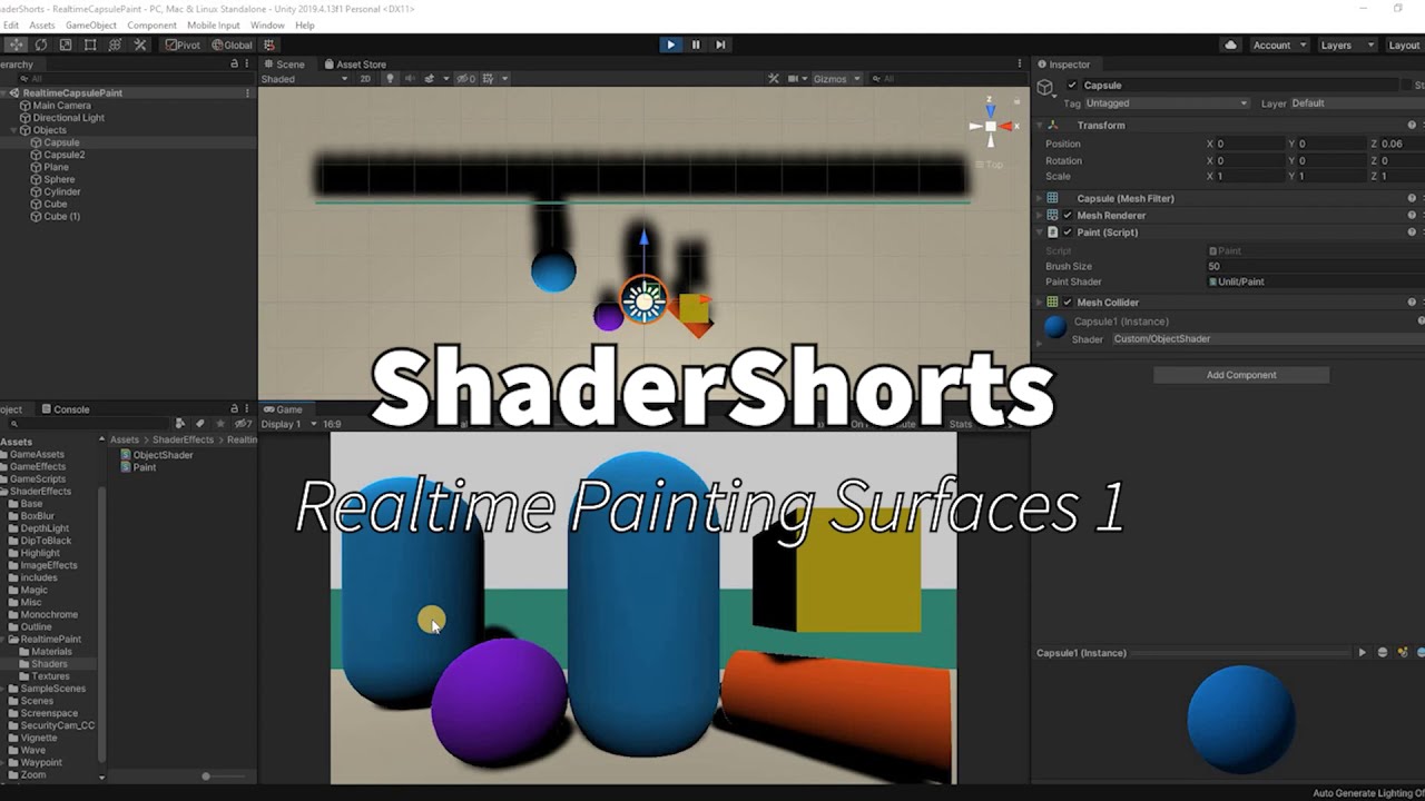
This is a series of short shader creation. Usually about 5-10 mins.
Follow along and create quick shaders for your games/apps. Learn by doing :)
This video gives an insight on how to paint a map in real-time using mouse as a paint brush. This has multiple use cases and is mostly seen while painting terrain maps or detail maps on objects.
How t...
That might help?
I'll give it a watch - I wasn't sure if there was some different implementation depending on if I was painting a 3d mesh or a 2d sprite (which I could also just fake as a plane with that texture)
Till the time you are getting uv coords your should be all fine 😀
thanks a bunch!
For a different project I was planning on looking at particle interactions with render textures (water ripples for example) but I wasn't sure how to approach this
There are various ways to create ripples, you can have displacement/alpha maps or height maps basically with some diffuse/albedo calculations 🙂
I was planning on using Remy's method to affect the flow map (for a river shader). Specifically placing rocks etc in the river with this method. I'll definitely check out if I can affect the flow map without using particles
https://halfpastyellow.com/blog/2020/10/15/Flow-Like-Water.html
If I have a render target with a depth buffer, is there any way to sample from the depth buffer of that render target? In my particular case, I'm actually just trying to copy the depth buffer elsewhere (I wasn't sure if this belongs in render pipeline or shaders, I'll try here first)
If I use eg buffer.SetGlobalTexture("_MainTex", _TempTarget);, I can sample the RT 0 of the above texture as _MainTex, but it has no access to depth buffer information
Where did everyone learn custom Shaders coding?
I tried looking on youtube, and there are tutorials on how to make specific looking shaders but I want to try learn how, if in the future I need a specific shader. I would go about it? if that makes sense?
I started at the beginning with Shader Graph, learn how to add standard textures, then normals, then emission maps, then go a little deeper with planar / tri-planar mapping and parallax occlusion mapping. And finally start adding effects, for each effect you add you can see how they interact and then start merging them etc to make better effects.
All YouTube. Thats how I went about it anyways @grand jolt .
If anyone wants to try and do a ps2 style game I recommend the vertex lit legacy shader, it definitely reminds me of games from that era
It provides that muddied look that games of that era boasted
i'm using the latest version of unity 2020, and i can't find the pbr shader graph create option. can anyone help me?
nvmd, forgot about the help menu in unity
blank shader graph
no, that doesn't look like any of the tutorials i've seen
it is what you want
then you can set pbr in the graph settings inside of the shader graph editor
it's changed in shadergraph 10.x, that's why it's different now
you will also need to set the active target to universal or high def depending on what you're using
then set the material to Lit (pbr)
other changes you might bump into is that the master node is now a 'stack', but that shouldn't be too different, and also the property settings like the property reference and value have been moved to the 'node settings' menu, they will show up there when you have a property selected in the blackboard
ok, thank you!
would be nice for Unity to introduce these new features inside of the editor, with like a little 'guide' that shows 'this is new', like a lot of other apps/software does, but I don't think that's ever going to happen
are albido and base color the same?
yeah I think they replaced that to base color
also for the properties, vector1 is now float
and if you don't see a certain output in the 'master stack', it's possible you need to add those, or maybe change something in the graph settings menu and then they'll show up
Hey Dane I missed this, but now I have not run into that simply because I haven't really used it since I wrote that article
@calm lynx well these things are specific to 2020.2, which was only released recently so you'll have to wait a bit for tutorials to catch up
true
but all tutorials should work fine, once you get the hang of those UI changes
they didn't remove any functionality
yeah. thanks for helping me out
hey guys can i ask a question about a shader graph thing?
Yes.
hahaha
that was actually funny
im trying to assign a material to a square sprite but when i drag and drop it remains white
i followed a tutorial on water reflection, so the material is a texture made of a camera view
it does work when i apply it to a quad
but not with the sprite

Learn how to create water reflection shader graph in Unity 2019.3+ for 2D games.
Water Texture download: https://www.textures.com/download/pbr0159/133194?q=lava
Free Asset - 2D Handcrafted Art: https://assetstore.unity.com/packages/2d/environments/free-asset-2d-handcrafted-art-117049
Links for creating 2D character for platformer games:
Drawi...
that tutorial
i was thinking that is maybe because of the different versions?
So why not use a quad?
because the quad is always behind the sprites, it doesnt have a sorting layer?
cannot find the way to put it in front
Also, if the shader is expecting a main texture then the sprite renderer component might mess that up by automatically assigning a blank sprite
You can set the sorting layer of a mesh renderer via code.
im not the programmer in the project😩
we are two dudes who know very little abut game development
but.. this is interesting
the interesting thing is also that in the video.. the dude effortlessly drags and drops the material into the sprite
and boom!
water reflection
you think you can give me an orientation on where to look? i can try, sometimes i do modify small bits of code here and there
we have a backup if anything happens haha
Um, I'm not at my computer so I can't send you it but I can toss an invite to a server where I posted a simple sorting layer script a while back
Sec
Cat
Lol
Anyone find my vertex shader suggestion helpful?
hey shader people
I found this awesome project here: https://github.com/AdultLink/HoloShield . It's not compatible with URP though. I just thought, gonna share it here with you guys. Maybe one of you decides to make a pull request with the URP version or something. I can just hope I guess.
Hello. Need some help as I can't figure out the problem. I'm trying to apply a texture and a transparent to a cube and can't get it to work. I have the texture in the albedo and the transparent in the secondary map, the shader as standard and the render mode as transparent.
NVM, figured it out. You don't need transparency maps at all, just an alpha channel and to delete the parts of the texture you want transparent.
Question: Why does depth writing from a transparent material completely occlude any other transparent material behind it?
And is there a way to stop that happening while still correctly sorting transparent materials
This is what happens to two opaque "transparent" queue objects without depth writing

Because your other materials are depth testing
and are behind the depth you just captured

It depends what order things render in, and what depth order they are in.
transparent objects are sorted by their object center for rendering, and typically would not render to depth
Okay, but why does an opaque material render perfectly fine behind a transparent material with depth writing on? Is the transparent pass after the opaque?
because opaque objects render before the transparency queue
you can see how the scene is rendered using the frame debugger
Yeah, depends on the setup
How does depth writing interact with sorting priority? Priority seems to override it, from what I'm seeing
they should be unrelated afaik
Thanks a bunch vertx, I think I may have solved it via sorting
Can someone please take a look at my question: https://answers.unity.com/questions/1800146/can-only-see-canvas-skybox-and-particle-systems-in.html

Unity is the ultimate game development platform. Use Unity to build high-quality 3D and 2D games, deploy them across mobile, desktop, VR/AR, consoles or the Web, and connect with loyal and enthusiastic players and customers.
build for what target operating system?
Didn’t work on WebGL nor the Windows, Mac and Linux one @eternal lynx
Weird part is that I can see the particles and the canvas, but not anything else. Think it might be a problem with the shaders then, but I tried changing to legacy shaders, and added the shaders to the prebuilt system so I can't really see why it isn't working then
hello, I just downloaded Shader Graph and I have something weird . . .EVERY asset lost their texture, what can i do to get my texture back pleaseeee
Think you need to update your textures to use the same shaders as given in the pipeline you're using. Go to Edit > Pipeline settings > Update Shaders to "something"
@radiant cobalt sorry to bother you but I really dont want break something x)
It is that ?
Yup!
thx ♥
Hello.
Shader grapgh pbr is not on the list when I try to create new.
what is the problem comes from
@limber fossil blank shader graph instead
Hi, I have this very simple unit shader that I want to use GPU Instancing with. However, when I enable the function from the material interface, sometimes the gameobject just does not show up at all (invisible). Am I doing sth wrong here?
the shader code does not have any instancing support written into it
which platform are you rendering for?
mobile, iOS for now, but the issue appears both in editor and the build
Check this out, I was just exposing model space matrix calculations:
The image was posted above sorry 😅
I...haven't really gotten it? I see you are doing matrix multiplication, but how exactly is it related to GPU instancing?
Sorry in advance, I am very new to shaders
Not related to GPU instancing
It's just a showcase of the amount of calculations a GPU does only for getting the model space transforms 😬😅

Benjamin Outram
Unity GPU instancing allows you to duplicate meshes without using much CPU overhead, which means you can render more cubes or more copies of trees, fishes, fractal geometries, or whatever else you can dream up! You can read more at in the Unity 5.5 documentation on GPU Instancing. To Instance a
Your question answered in that Blog 😀
I'm trying to create the line of sight effect using Sebastian Lague's tutorial, and it works just fine but I want to make the FieldOfView always visible like a transparent white color
@quaint coyote Sorry for the misunderstanding haha, will look into it!
When using Parallaxing the Input is a Texture2D as the map, does anyone know a way I can convert a noise node to be compatible with that?
@mellow rover no worries at all man, all cool 👍
@low moth did I miss the reference?
?
It wasn't related to your discussion
I meant reference to Sebastian's shader 😅

In this bonus episode we create a stencil shader to achieve a cool limited FOV effect.
Source code:
https://github.com/SebLague/Field-of-View
Some links about stencil shader:
http://docs.unity3d.com/Manual/SL-Stencil.html
http://forum.unity3d.com/threads/unity-4-2-stencils-for-portal-rendering.191890/
Support my videos on Patreon:
http://bit....
They're in the description
Anyone know why the HDRP Unlit "Distortion" option might not be doing anything for me?
I can't find any documentation on it besides the very unhelpful "Click this to enable distortion!" on the docs
hello
I'm having this issue
I'm using TMP and as you can see, the text is beeing shown even when there is hardly any light.
It seems as if it was emitting light.
What can I change to modify this behaviour of TMP?
I reccomend a legacy vertex lit shader for ps2 or retro styled games
Hi there, is there someone open to explain me some shader code in a call? About 20 lines only, super basic stuff but for me hard to handle with the time I have...
It is from here:
Medium
Triplanar mapping is a great solution for dealing with texturing on complex geometry that is difficult or impossible to use traditional UVs…
thanks. but where is it? Has it been abolished?
@limber fossil where is what?
pbr graph example
if you want pbr shader, make a blank shader graph, then set render target to universal or high def, and then set type to lit
blank shader graph -> set to lit is the new pbr
yes I see. but there was a PBR shader instead. So initially we had some features with it. But when I create a blank, I have to start from scratch
nah, if you create a blank graph and set it to 'lit', you have everything you initially had with PBR
oh my gosh
that's really the new way to make a pbr shader
you'll see the master 'node' is now a master 'stack', and some of the settings you got by clicking on the cogwheel on the master node, are now moved to the 'graph settings' window
sir thanks!!
Any idea why ShaderGraph doesn't generate passes for TerrainDetailVertex? eg, for detail objects added via terrain
does anyone know how to increase the max render cap for nodes in Shader Graph? I seem to have hit some sort of limit and my nodes are now invisible...
I'm making a 2d isometric game and have sprites in my world which can hide the player. I want to make it so that if the player walks behind these sprites, I sort of have this effect where I "punch a hole" through these objects and render my player. How could I use a shader to achieve this?
@placid kettle if you are using sprite renderers, you can use the default sprite shader. look up sprite masks.
Hey, I tried switching my project to the HDRP, but most my textures looks like untextured metal (ignore the purple textures). Is this a common problem? I saw some videos on HDRP and I didn't see this problem. Tips?
@fathom temple i think you need to convert your materials to HDRP materials, it's in the HDRP configuration.
i did convert them. The purple textures in my picture are the ones not converted yet, but the rest is set to HDRP Lit
@fathom temple you have too low light intensity
HDRP expects quite high directional light intensity by default
alternatively you have to dial down exposure values from multiple places
It's weird, because when I turn up my intensity, it gets brighter but slowly fades back to dark. I'm not really sure what these exposure values are though
that's autoexposure
basically easiest way you can make it use proper values quick is to do following:
- run through HDRP Wizard, make sure everything is green
- create a new HDRP scene
- make prefab out of the directional light and sky volume from this new scene
- open your existing scene
- replace the directional light with your light prefab and add the sky volume prefab
of course you can manually configure all this but it's simpler to do what I just listed if you are new to all this
Also make sure your materials are properly converted, with textures in the right slots.
Hey guys, How can I make an outline shader for my multi-sprited character ? I mean my character has it's body parts separated. like in the right side of screenshot below.
does anyone knows how to fix this problem? https://i.gyazo.com/b82afbcc1eed3d810dc8ef8f7b1faed7.png

i've tried to convert a written shader from built-in pipeline to urp but i get this error
when writing HLSL shader, is there a way to make a constant shader variable that can be edited through the editor and be used in the code, but not be edited during runtime?
I tried "copying" this material (with the given textures ofc) to another Unity project
but the outcome is different.....
I'm doing some vertex animation, and I've noticed that the shadows get dragged along the surface of the meshes (e.g., when rotating the object the shadows are still calculated as if the vertex aren't moving at all
what could be the cause?
URP Pipeline, tried adding #pragma addshadow but nothing changes
@slow bear Are you referring to the shadows cast by the object or shadows received?
Shadows received, basically it's still calculating the shadows as if the mesh was still, but I'm rotating some of its parts based on their vertex colors
Okay, so are you handling shadow calculations using GetMainLight(shadowCoord), or maybe MainLightRealtimeShadow(shadowCoord)? Either way, that shadowCoord should be calculated from the offset position.
@south glacier Other than the Height Map slider it looks the same to me. Since it's for the Universal Render Pipeline make sure URP is set up correctly in the other project. Maybe also try right-clicking the material and Reimporting it, that might fix the magenta error, not sure.
Consider that I'm using Amplify Shader Editor to save time
and I'm using a PBR template, but even when calculating NdotL manually the result is the same
Ah, okay. I'm not familiar with amplify. Seems strange to me that it wouldn't already handle it automatically.
I'll remake the shader in Shadergraph and see if something changes
Oh, you're referring to the dark areas produced by N dot L and not actual shadows. You'd need to change the vertex normals to change that shading
it's weird though, I mean, any surface manipulation that happens in the vertex program phase should carry on to the surface program
I'll post some screens
this is at t = 0, this is what the mesh looks like without any manipulation to the vertices
This is after an almost 180 rotation on the Z axis: notice that the shadow is literally rotating along with the surface, and how some faces appear flat-shaded instead of smooth as they should be
@regal stag yeah I just fixed it by readding the URP Config in Project Settings, forgot to do that. Thanks!
I think you need to look into rotating the vertex normals as well as the position.
Not really familiar with that error exactly, but since it says syntax error maybe there's a missing } somewhere? If this is a surface shader it's not going to work in URP, only vert/frag ones will. If it is a vert/frag one maybe share the code and someone might be able to spot what's causing the error.
Maybe use a shader property? It's up to you when you edit/update it then
isnt there like a limited number of properties that can exist though?
I know there's a limit to shader keywords but not properties afaik. If there is I've never encountered it.
what exactly is a keyword? im very confused about it
They're used to create multiple versions of a shader where features can be toggled, with and without code included. https://docs.unity3d.com/Manual/SL-MultipleProgramVariants.html
The Standard shader is an example of such a shader that uses some keywords to enable/disable parts of it so if you don't need them all the shader isn't doing unnecessary calculations.
I've got a question on the forums if anyone has any insight:
https://forum.unity.com/threads/hit-shader-graph-max-node-render-cap.1030054/
Unity Forum
Hi all,
I'm using HDRP 2020.2.1f1 and i'm in Shader Graph 10.2.2 , but I seem to have hit some sort of render cap for nodes as new properties and...
Haven't really used 10.2.2 so haven't encountered anything like that. Might be a bug. Does using sub-graphs help at all?
That must be it, thanks, I thought vertex normals would get updated along the vertices positions
turns out they don't
Also, i'm leaning towards a render cap because the nodes are still fully functionable, I can still connect them, they are just invisible, which means i cant edit any of the default vectors on them, and it only happens after a certain amount of nodes have been added, so i started using nested sub-graphs which helped, but like I said it's all sub-graphed now so sort of hit a wall @regal stag
Is there any way for me to make the inspector menu of my shader graph more organized? With tabs or titles? I'm guessing shader graph itself doesn't support this yet
I'm not enjoying this mess of properties I got going on very much lol
I think there is ShaderGUI
Not sure if this is of use, but I just discovered the hard way that Linear01Depth doesn't work with Ortho! Specifically, it introduces some nasty bugs if someone sets the near plane to negative.
Yeah you can make your own ShaderGUI if you're up to it and assuming you're on a shader graph version with the Override ShaderGUI option on the master node
I think there might also be plans to add headers/titles into shadergraph?
@teal breach You could probably use a clamp node to counter that negative near plane issue....not entirely sure
on the productboard they say 'blackboard categories', but I'm not sure if that would translate to the material inspector?
Linear01Depth is intended for perspective as the depth buffer is stored in a non-linear way. For orthographic projections - it's already linear so doesn't need to be converted
they just say 'group and categorize properties on blackboard'
Ah right. I assumed it would be both blackboard & inspector but I guess that might not be the case
@regal stag I get the reason why, just would have expect it to 'do nothing' in that case. I should have read the source, it does clearly state it in the hlsl file
I was hoping there would be some convenient high level function which makes everything be nearest=0, furthest=1, for all gl/dx and ortho/perspective variants, but I don't think there is 😅
Yeah don't think there's a convenient function for it. Would have to handle it yourself. I think it would be something like
if (unity_OrthoParams.w == 1){
    orthoLinearDepth = _ProjectionParams.x > 0 ? rawDepth : 1-rawDepth;
    orthoEyeDepth = lerp(_ProjectionParams.y, _ProjectionParams.z, orthoLinearDepth);
}else{
    linearDepth = Linear01Depth(rawDepth, _ZBufferParams);
    eyeDepth = LinearEyeDepth(rawDepth, _ZBufferParams);
}
For URP at least. Built-in would probably be the same but without the second _ZBufferParams parameter. Unsure about HDRP.
so, in my case I'm having to use some shader keywords, because the actual processing is occuring during a post processing phase (and not when the depth values were written)
in the render feature I'm setting the keywords based on the cameraData
Hey, this may be the wrong channel but is there a way for a 2d sprite to take damage from being hit with bullets? Like in Space invaders pieces of the shield come off where it was hit, is there a way to do that in Unity?
do you want the damage localised, or would a general 'look of damage' do?
localized
I wonder if it can be done on a skinned sprite
That's my eventual plan
I'm thinking of something really complicated and I'm not sure it's even possible
easiest way might be to just have detachable objects that you drop off when taking damage
like gibs (reminds me of cortex command, if you ever saw it)
I want to do a 2d version of what they do in Doom Eternal, where chunks blow off of a character

like there's a skeleton underneath but there's a sprite on top that breaks off
I'm not sure that can be done
I guess that is done by procedural mesh generation rather than shaders - i think the feature you want is called fracturing?
yea
i can just parent skeleton sprites underneath without actually skinning those
those won't take damage
I just looked up fracturing, I don't need them to become separate sprites
I just want pieces missing off of the main sprite
or sprites
I don't know what would be better
There's a lot into this that I want I need to tackle these issues one at a time
I think what I want is splotches subtracted from the sprite
localized damage
I don't want the part that falls off to be its own thing though, I can do that with particles
Might be able to send impact points to the shader (e.g. in a Vector array) and discard pixels (or change their alpha to 0) based on the distance from the fragment position to those impact positions. They would be perfect circles unless you also offset it with some noise.
It might be awkward to handle with sprites though. I think multiple sprites tend to batch together which messes with the object-space fragment pos. It would likely need to be handled in world space.
is it possible for a sprite to keep track of what's been subtracted from it?
If that's the case I think skinning it should work fine
I guess what I really want is like in that movie Bloodshot
it's hard to explain, I guess i want it to take damage but regenerate
like a reverse burn
so damage will do a local burn dissolve, but it slowly reverses over time
does the keyword UNITY_REVERSED_Z work with URP? Whatever I do it seems to have the same value for both DX and openGL
(keyword wrong word - global define? whatever its called)
I think it should have a value of 0 for openGL and 1 for DX. Might be a bit different from the built-in pipeline - where I think it's not defined at all in openGL?
I'm finding the following is using the defined() route for both openGL and directX graphics APIs on windows #if defined(UNITY_REVERSED_Z) depth = raw_depth; #else depth = -raw_depth; #endif
(target is webGL - will check if that makes a difference)
Think you just want #if UNITY_REVERSED_Z rather than #ifdef / #if defined, as it's always defined it both, just with a value of 0 or 1.
ahh, ok! I'll test that. The manual actually explicitly uses defined https://docs.unity3d.com/Manual/SL-PlatformDifferences.html
Yeah, the manual is written more for built-in pipeline. It works differently in URP now
cool, thanks Cyan. Happy it works at all 🙂
@devout quarry just out of interest - how do you link your shadergraph to a specific ShaderGUI? Is there a way to specify CustomEditor in the shadergraph?
yeah like Cyan said, it's on the master node, click on the cog wheel and then you can enable/set it there, just by entering the name of your class
for 10.x it's under graph settings I think
but I don't think custom shader gui is for 7.x, only 8.x and above (I think)
I think that's where I was missing it, I'm still on 8.2 (but need 7.x compatibility)
courtesy of cyan's water shader breakdown (https://cyangamedev.wordpress.com/2019/06/10/water-shader-breakdown/) I've been figuring out this cool projected caustics effect,
but I'm having trouble wrapping my head around making it fade beyond a certain point so it doesn't project all the way over the walls
or at least not as intensely
@hearty wasp you could fade based on depth?
also to get rid of those vertical streaks, you might link up the light direction matrix so the caustics seem 'projected' from the light direction instead of top-down
I've been thinking about that yeah, and I do already have a little depth set-up in place for the colors, so I'm sure I could figure it out if I give that some more thought
this might be a bit beyond my ability however haha, these caustics aren't truly projected into the world to begin with but instead just rendered to the plane as shown in cyan's breakdown
yeah sure but it's still a projection
I see in my code I actually do this
                half upperMask = -positionWS.y + (_WaterLevel - _CausticsStart);
                half lowerMask = positionWS.y - (_WaterLevel - _CausticsEnd);
half heightMask = smoothstep(0, _CausticsFade, min(upperMask, lowerMask));```so a mask in world position, relative to some defined water level
and so for that 'projection' I do this
half2 uv = mul(positionWS, _MainLightDirection).xy;
and you can get world space position from depth, and mainlightdirection is the main light's rotation matrix
I know you use shadergraph and all, but just wanted to share, it might be of use
I've used getting the main light's rotation in a shader before so I may try and look into it, shadergraph is a blessing because I'm way more visually orientated so I'm already doing stuff I wouldn't be able to wrap my head around otherwise
Still having issues with this, if anyone can help:
https://forum.unity.com/threads/hit-shader-graph-max-node-render-cap.1030054/
Unity Forum
Hi all,
I'm using HDRP 2020.2.1f1 and i'm in Shader Graph 10.2.2 , but I seem to have hit some sort of render cap for nodes as new properties and...
anyone around that has experience with texture arrays?
@radiant inlet use the object position or uvs rather than screen or world coordinates?
does someone know other method to create a gray effect over the camera without forward renderer?
@normal rose can you be more specific?
so, i want to create an night vision effect but on grey, soo i searched on youtube some tutorials but all the tutorials i found use a forward renderer with a shader graph material but my question and problem it is, is there a way without the forward renderer because when i switch from the default one to the scanner renderer , i lost around 10 fps
@eager folio i have a position node on my shader that is set to object position
if you are using URP there is only forward renderer available at moment, in default you have a choice between forward and deferred. It should not really affect fps that greatly. It maybe more down to how the shader is created / employed and what platform you are targeting
what do you mean
how do you make it stop?
@limber fossil what do you want it to do
I made a dissolve shader. When my player jump out of the standing platform, I will change shader to my custom shader and it will be disappear.
you need to change the shader with code
I've never done that before but you have to look up how to change materials
don't change shader I meant material
in your sprite renderer
hmm. ok and one more problem. why on earth my shader works in editor mode.
I mean I did not get it played but it works in scene own by own
dissolve shader works without clicking "play"
yea it shows you the shader is working do you not want it to do that?
I want but only when I start the game.
Oh got it.
I have to change during the game right?
it depends on what you want
There is a standing platform. When my player jump it will be destroyed. I mean I will change my standart shader when player jumps.
and the platform will be destroyed with shader that I made. and I will turn off the gameobject
you should have a script that sets the dissolve to do that
in Brackeys dissolve tutorial near the end it shows a script on how to change your shader and materials
hmm. Is there any event function for it? kinda animation events. I mean when the shader worked once, I want to get informed.
thanks
Ill take a look now!
If the shader is using a Time node, you could swap that out for your own float property and control how it dissolves from a C# script (material.SetFloat https://docs.unity3d.com/ScriptReference/Material.SetFloat.html).
you are a hero! thanks
yea that's what's in Brackey's video
is it more efficient/optimized in shader graph to reuse nodes? say, if I already had a time node it'd be better to reuse that time node rather than make a new one?
depends
I'm not sure it's that much more of a memory usage to add a node
if they're doing the exact same thing, then you should be able to use the same node
and you don't want to use them independently
It depends exactly what node is being reused. Nodes that handle "inputs" like the Time node, or Position node are just accessing a variable that's already been set elsewhere.
But if it was something like, a Transform node where you're converting a position between two spaces, it's better to reuse the output rather than having another Transform node doing the same thing.
Hey @regal stag, do you happen to know how to fix my issue I had last night? If you scroll up a little bit it's the last video sent
I want the shader to stay on my player's position
and I have a position node set to Object in the shader already
Sprites tend to be batched & drawn together for better performance, so "Object" space isn't really a per-object thing anymore, I think it's just the same as World. You'd have to use UVs to keep it fixed to the sprite
how do I do that
UV node rather than Position node
ok
It should also use UVs automatically if you leave the UV input on the noise node (or texture sample) blank
well it's not
does it matter if I do UV1 or UV2 i don't know what those are I've been leaving it at UV0
so I left my Noise node UV input blank and the Sample Texture 2d UV input blank also and it's doing the same thing
Probably just leave it at UV0. I doubt there's any values in the other channels for sprites.
Did you save the graph?
yea
nevermind I guess it works now
I didn't save it after deleting the position node
I have a rotation node that used the default UV0 input
oh man it works great now thanks
By the way, How can I change my property's value inside graph editor. It is deprecated?
if you're in 2020.2 you click on the property and then open the node settings window in the top right
if you still can't find it I can provide screenshots once my unity launches
I found it. But not usefull to take the propery settings all the way right to the screen.
Thanks
Hey, when I try to apply a material with a ShaderGraph on my sprites, it turns white and I get the error message "Material does not have _MainText property" can anyone help please?
check inside your shader graph, look at the Main Texture 2D input you have on the properties list on the left. You need to change the Reference name of that to _MainTex @south glacier
you can change the actual property name to Main Texture, it's the reference below it that needs to be _MainTex
you can find it in Node Settings (top right property box) when you click it
Works now. Thanks alot!!
So, according to the unity doc (https://docs.unity3d.com/Manual/SL-SamplerStates.html), you can specify the filtering function of a sampler through the sampler name. eg, sampler_point_mainTex. It's not clear to me what the syntax should be for using the sample though, using URP. For example, using SAMPLE_TEXTURE2D(_MainTex, sampler_point_MainTex, uv) just gives an error
does anyone know of an example they could point me to?
it's probably something ike sampler_point_trilinear @teal breach , as your already sampling _MainTex with the first input, not familiar with the scripting method though
the filter is either trilinear or linear im guessing
cheers, this got me in the right direction. Looks like you also have to specify the wrap mode, or it won't work - you can't just provide a filtering mode. Eg, sampler_point_clamp works
Im two for two, COME AT ME SHADERS
Can someone help me so that the material/shader scales the images based on scale so that they don't stretch please?
Hello. I have some objects inside the scene. All the objects use the same shader and I want them to be affected individually. When I click one, It will be dissolved but other will remain what they was. What should I do, Should I create individual materials? Or is there any solution for this?
@limber fossil you can use .sharedMaterial instead of .material, that should effect all objects with that material
I made a dissolve shader and with float property I manuplate it.
I have 100 objects inside the scene.
When I click one of the objects, It should be gone with that dissolve shader.
what do you suggest to me.
but my purpose is to use it individually.
Thanks Ill take a look now.
you can use the tiling and offset node
Hello! Does anyone know the name of the rendering technique/shader used in top down games (Among Us for example) where the objects are hidden/partially hidden depending on the field of view and obstacles between the player and the object? Thanks!
Theres two effects going on, fog of war, and the actual masking. The fog of war could be done with linecasts to the corners of objects (see here for some description: https://www.redblobgames.com/articles/visibility/) As for the mask maybe look into using the stencil buffer? I dont know too much about 2d rendering but that might be a good place to start
Will do, thanks a lot!
of course!
I'm making a low poly game, and some assets I've found don't support HDRP, but they do support URP. Is there any way to make these assets work with HDRP or should I switch to URP?
So when I do that, all of my purple textures are fixed, but some of them turn grey and look untextured/uncolored. The snow material seems to be working though.
These assets are from the Synty Nature Pack btw, and I don't think they support HDRP? At least one of the comments mentioned it.
Still seeking an answer to this, not even sure if it's a bug:
https://forum.unity.com/threads/hit-shader-graph-max-node-render-cap.1030054/
Unity Forum
Hi all,
I'm using HDRP 2020.2.1f1 and i'm in Shader Graph 10.2.2 , but I seem to have hit some sort of render cap for nodes as new properties and...
@fathom temple put higher intensity directional light value
basically this is coming from HDRP default that expect such higher intensity lighting values, alternatively you have to dial down exposure from multiple places
by higher value, I mean like in range of 10 000 or 100 000 (can't remember which they default to nowadays)
@fervent tinsel I think I already did that, which is why my snow texture on the ground is showing. (Kinda hard to see since its a subtle texture) I have gotten other assets from another unity package showing up in color though. Not on my computer otherwise I could show the pic
It's not possible to specify the sampler filter for openGL platforms in shader (eg, using sampler_point_clamp or similar). What other options are there for a temporary render target?
You can use GetTemporaryRT outside of the shader (eg in a scriptable render pipeline feature) to set the filtering for a render target, but this only works for creating a new one. If I want to sample screen color with a point filter, for instance, this doesn't work unless I blit the screen color texture to my own render target, which seems a bit wasteful
How can I make other light effect my shader in Unity .shader code ?
I'm using 2019.4, how do I see properties for these colors? can you not do it in a shader subgraph? sorry i'm just confused af on how subgraphs work
The properties in a sub graph is used for the input ports into the node when used in another graph. You can't expose the properties in the sub graph directly, they would need to be duplicated in the main graph and dragged into the node inputs.
thank you :)
also, how do i have more than 12 texture units in a shader? i need quite a few layers of masks for this material. just asking here now since i got a quick response
i thought that i could use subgraphs for this problem but i don't think i understand how they work very well
If you're reaching a limit on texture samplers, you can connect a Sampler State node to the Sampler(SS) port on the Sample Texture 2D nodes. (It's the same as "inline samplers" in code form : https://docs.unity3d.com/Manual/SL-SamplerStates.html)
Usually the limit is 16 samplers, but I guess the pipeline might also be using some up for stuff like shadow maps, lightmaps etc. Using inline sampler states instead of the ones created for each texture can avoid the limit
@feral inlet Adding to what Cyan said, these SamplerState nodes WILL override any import settings you have, for example, if your texture is set to clamp in import settings but you have a repeat sampler state node attached it will repeat the texture, so make sure you match your sampler state nodes to the appropriate types
final question, and now i'm editing a regular shadergraph. i can't find the properties window. i know in newer versions there's some sort of properties panel on the right, but this seems to be different. how do i change the default colors? etc?
The properties are still listed in the Blackboard window, but their values (like the reference, default, etc) is found in the Graph Inspector window under the Node Settings tab, while the property is still also selected in the blackboard or graph. https://docs.unity3d.com/Packages/com.unity.shadergraph@10.2/manual/Internal-Inspector.html
(It's a bit awkward so I'm hoping for this change to be reverted tbh)
Node settings tab? maybe i'm blind, but when i click on a property i don't have another window
i'm using 7.3.1, not sure if that's why or if i should be using the latest
Oh, if you're still on older versions the properties are listed in the Blackboard window. There's arrows on the left of each property to expand the settings
If the blackboard isn't visible there's a button in the top right of the graph somewhere to toggle it
when i click on a color nothing happens. maybe i'm remembering how the graph editor works incorrectly
I know others have mentioned problems with the colour picker window not appearing. It's probably a bug in that URP/shadergraph or Unity version.
thank you for the help, i'm going to try to restart unity and if it doesn't work i'm just gonna use a preview version of the shader graph, might even use 2020 instead
Surface shaders handle them automatically yes. See "Surface Shader input structure" part of this page for a list : https://docs.unity3d.com/Manual/SL-SurfaceShaders.html
It's not too clear, but worldPos is likely the vertex/pixel world pos, not just the object's origin.
unity_ObjectToWorld._m03_m13_m23 should get the object's origin in world space
Though that will only work if the object isn't static or dynamically batched.
Maybe here https://docs.microsoft.com/en-us/windows/win32/direct3dhlsl/dx-graphics-hlsl-intrinsic-functions
The following table lists the intrinsic functions available in HLSL. Each function has a brief description, and a link to a reference page that has more detail about the input argument and return type.
@hearty wasp generally noise is expensive yeah
but a 'noise texture' is different than the gradient noise or voronoi nodes in shadergraph
a noise texture is a texture, which would be the noise function, baked into a texture
Does anyone know how to get lighting information, specifically shadows, in the latest version of shader graph?
Also have this https://github.com/Cyanilux/URP_ShaderGraphCustomLighting
Though I haven't tested it in v10+ yet
I'll look at both, thank you both
went a bit overboard with a sub-graph 😄
that must be a record, wow
it's not finished yet...still have to add around 30 more
Out of curiosity, what does it actually do?
it's an Info Box Effect, it's designed to go on standard Unity cubes, it lets you render textures on each face, with about 4 built in effects, all controllable per-face 🙂
it looks a bit non-uniform right now as i'm messing with all the effects, but heres a screenie @regal stag
thanks for answering! noise texture was the wrong choice of words but if I understood you correctly a way to optimise my shader would be to use a noise texture instead of a noise node
it depends on the effect you want to achieve, i have an animated pixel effect but it only works via a pixellated UV thats animated, it wouldnt work with a texture @hearty wasp , but yes, if you can get away with a texture it's better
I think generally a tileable noise texture would be better in terms of performance than a noise function node yes, but for performance it's hard to speak in absolutes so I'd say test it out
it's always good to gate stuff behind bools too, so you need to activate a bool to use said effect
you literally answered the question I was just about to ask haha
yeah I had booleans in place but I wanted to ask if it actually mattered in terms of performance
but don't use comparison nodes for that, both branches will still be evaluated I think
although i'm not entirely sure of the computational advantage of that, Shader Graph seems to do everything then your bools just switch whats showing, where as in a script you IF check something before it bothers doing further calculations
use shader features for that
oh, variants? yeah, that works
unless your me, who has such a massive shader I had over a million variants at one stage XD
yeah that's with multi-compile, but I think with a regular shader feature, only a single variant will be compiled in the end for your build?
and with multi-compile, it compiles all the variants as well (and they add up fast) to be included in the build
I think
so this doesn't actually matter? false being a noise node and true being a texture
I think both are computed yes, and only the visual output is different, so I would use a shader feature there to switch between them
but honestly, I'm not 100% sure
yeah, it's definately good for a build if you can do a multi, more performant at runtime, the problem at the moment for me is i cant convert anything to be a variant, because adding even a single keyword atm means my graph takes like 4 minutes to compile every time something changes XD
Yeah, I'd use a Boolean Keyword rather than a Boolean Property. That way you can guarantee only one side is computed.
^
make it one of the last things you do though
otherwise your compile time will go through the roof
yeah but I think you're really pushing the limits with your graphs lol, I've never had issues
well my pc is trash, maybe it's far faster for others
I hadn't ever heard of Boolean Keywords before, thanks Cyan, no idea how I never came across it before
I think shader features still produce the same amount of variants, it's just unused ones won't be included in the final build.
Also be aware that there is a 128 variant limit, that you can increase in the preferences
you're right cyan
yeah Strip Unused does that in the settings for it
I'm guessing there's no way to actually hide properties based on a Keyword in shader graph yet?
with a custom shader gui, yes
then you can do something like this
        {
            editor.ShaderProperty(rampTexture, "Gradient");
}```just add _ON to the end of the properties reference name to expose the Keyword @hearty wasp
keywords reference name*
where do you recommend I start learning about custom shader guis, to actually teach myself some basics? I tried looking around a bit but it's a bit daunting as someone who's only really worked with nodes
you could just start from the docs and go from there
also here is an example of one of mine, but I would look at the docs first since their example is much cleaner
where do I actually access the code of my shader graph shader? or rather, what's a good workflow to use? after looking it up, a forum post I found is saying I should first generate it to a regular shader file
can you go back and forth between graph and code?
If you're in shader graph 8.2-ish onwards there's an option on the master node to override the Shader GUI, so you don't need to edit the generated code.
ah okay I'm in 10.x
Okay, the Override ShaderGUI option should be in the Graph Inspector window then
For the record, the Generate Code from graph option is in the normal unity inspector window, when you click on the graph in the project window
But once you generate code it's a separate shader. You can edit it, but it won't make changes to the graph.
I'm still used to sub version 10.x and I'm not sure where to find this Override ShaderGUI option
I think in the Graph Settings tab
It's labelled Custom Editor GUI looking at the docs https://docs.unity3d.com/Packages/com.unity.shadergraph@10.2/manual/Graph-Settings-Menu.html
oh right, I see it
thank you, I got it working now
and this is where I should reference to the path of the custom GUI script?
or am I misunderstanding?
I think it just needs to match the C# class name of the custom Shader GUI
I haven't actually used it so not 100% sure though
I think this is the point then where I should go off and watch tutorials/read resources haha
thanks for the help, guys
In DrawProceduralInderect one of the arguments is a bufferWithArgs
Does this mean the buffer ONLY contains buffer arguments or also data concerning vertices etc?
Seems like the former based off this I found on github
sup
texture( sam, p.yz ).xzy; how can I do something like this in a compute shader?
im donig this but the results are different than my normal shader
iChannel1.SampleLevel(sampler_iChannel1, p.yz, 0).xzy;
It's been a while! Just wanted to thank you again for the help. Turns out the issue was that I was using OnPostRender on a script that wasn't attached to a camera xD
so just wondering regarding how I could accomplish this
ive got tiles like this
I want to make a projectile hover over these tiles, and based on its current location i want the white part of the tile to light up a certain color to indicate that its hovering over them currently
problem is that, i want it to only light up a part of the sprite, sort of like this:
the pink is supposed to be sort of like a fading effect but I couldnt find a good enough color on the default windows paint palette lol
but yeah, is there a way I can accomplish this?
preferably vertical too
as a note, each of the tiles are its own individual sprite
Change the wrap mode in the texture's import settings to Repeat rather than Clamp, (or override it in the graph by connecting a Sampler State node to the Sampler(SS) input on the texture sample node)
hey guys i have a bit of a math problem but i don't really know where to post it but it is in a shader so i will post it here if that is okay, say we have a circle with a given radius, and a point inside the circle and a direction as well, how long would the point have to travel along the direction in order to reach the circumference of the circle?
@real gorge circle is defined by distance(p-c)^2 = r^2 with p a point on the radius, c the center, r the radius
if your point inside circle is a, the line of its direction would be defined by a + td, with a being the point, t the units travelled along the line, and d the direction
so a point p(t) on the line is defined by the equation a+td, so if you use (a+td) instead of p in that original equation, you'll get a solution for t, and that's the distance the point would have to travel
basically you need to solve intersection between line and circle, that will give you 2 intersection points, and then you take the distance between one of those points and your original point to get the distance
@devout quarry thank you very much for answering, i really appreciate it but i have a few questions, what do you mean by "with p a point on the radius" did you mean a point on the circumference? sorry if im being slow
yeah that's my bad, that's indeed what I mean
just in that first equation, p would be a point on the outer edge of the circle
i understand that distance( a, a + (d * t) ) = t but how do i get a + dt?
a is your point inside your circle (x,y,z), t is variable, and d is your directional vector
so you want to vary the variable t, until you get a point that also satisfies the equation of the circle, and that's your intersection point
so keep varying t until the length(a + dt) = radius and then that's the solution?
yeah, I mean my notation doesn't matter that much, but you said you have a point and a direction, inside of a circle: a point + direction, defines a line, and you can calculate the intersection point between a line and a circle, and at that stage you have 2 points: your original point inside the circle, and the calculated intersection point, and you can calculate the distance between those 2 points for your answer. would be good idea to look up these concepts online for some implementations, also I'm not sure if this is the optimal way to calculate it in shader in terms of performance, but it's the most intuitive way
and no that's not right
your point a inside the circle + your defined direction, gives you a line
each point on that line, let's call it p(t) satisfies the equation 'a+td' where a is your point inside the circle, and d is your direction
so you plug in p(t) in your equation of your circle, and solve for t
if you get for example t = 0.3, then your intersection point would be p(0.3) = a + 0.3 * d
so if your point a is (0,0,0) and your direction is up, like d = (0,1,0), your intersection point is (0, 0.3, 0)
I'm trying to scale an image up and down in shadergraph, from the center point. how do i do it?
Should work with this : UV node -> Subtract (0.5, 0.5) -> Multiply by scaling value -> Add (0.5, 0.5) and put the result in the UV input on the Sample Texture 2D
how many textures can you have per shader state? and how many shader states can you have per shadergraph?
i did a massive tree of colors + masks + lerps and i'm not getting an error, and it shows up fine in the preview, but in the scene view it's just one of the colors i used higher up the chain.
ex
Anyone know why my vertex coloring would be doing this? I have put a solid R G B in each corner, (only one color per vertex) and I'm getting these weird 'lines' all over and it makes textures 'stair step'. (ie. see the yellow/purple/green lines) Is there a way to stop this, or blend them differently? (the black dots show vertex locations)
(this was painted on a flat mesh grid with equal vertex spacing)
Still seeking an answer for this:
https://forum.unity.com/threads/hit-shader-graph-max-node-render-cap.1030054/
Unity Forum
Hi all,
I'm using HDRP 2020.2.1f1 and i'm in Shader Graph 10.2.2 , but I seem to have hit some sort of render cap for nodes as new properties and...
@wind flame hmm how is this not the intended behaviour exactly? It's blending between the colors right? what effect do you want?
the 'lines' you see make sense to me, if you've put RGB on those vertices
it interpolates per triangle, if you single out a single triangle, it looks fine, those lines you see are just because you put those triangles edge to edge and no interpolation happens between triangles, only within a triangle
why would there be a sharp edge tho?
of yellows/purples, etc
shouldnt it look like this?
yellow is because it's blending red and green, purple because it's blending blue and red
yeah within a single triangle it should look like that, but it does in your image right?
not even close
take a look
the colors band away only in a line
maybe my mesh triangles are being constructed in an order that isnt lining up with my vertex coloring?
would that cause it?
the yellow stays consistent across the whole long edge, so something has to be wrong no?
(its like on all edges its 'over multiplying')
but that yellow line, is between 2 triangles right?
yeah, inbetween 2 separate ones
yeah so that makes sense right?
for each pixel within a triangle, it interpolates between the vertex colors
here ill post a pic of the texturing...
that doesnt look normal to me....
see the hard line in the upper right between to vertices... it should naturally be more traingled. not 'boxed' looking, shouldnt it?
especially right here.... something has to be wrong:
and here is a texture on just 1 vertex... shouldnt it be a nice smooth circle... not have those lines running away from it? (its like the color value along those points is way higher than it should be)
hmm maybe I'm wrong but to me that just seems like a limitation of the technique, vertex attributes get interpolated within the triangle but nothing special happens between triangles
Are you expecting something closer to this?
well that would be better....
here ill mock up what i thought it would do
like at that same single vertex point, i thought it would 'smooth' away in all directions
cause its just a single splotch of color on all vertexes anyway
why does it have 'lines'
it has lines because it's an edge between two triangles, and no interpolation happens between the triangle edges
is there anyway to make it look closer to my mockup?
or is this just a limitation to vertex painting?
for sure one way is to increase vertex density but probably some other tricks that I don't know about
If you at least add an extra vertex to the center of each quad and break it up like so, you could achieve this
Yeah, that's just how the interpolation works
hm... i honestly expected there to be a math blending mode, that would remove that effect
thats unfortunate
but if you increase vertex density, it should get much better
right
If you want a perfect circle, it would have to be a per-pixel based approach, maybe something like a texture splatmap
hmm... well im technically using this vertex coloring as my splatmap
Yeah, so you could swap it out for a hand-drawn texture or something instead. Similar to what the terrain system uses
and im texturing it via the fragment shader
that's indeed good to mention, with vertex colors you'll always be limited by your vertex density, moving to the fragment shader will give smoother results but is more performance intensive
hmm, alright. ill think about some things. I appreciate the help Cyan and Alexander. Cheers!
reposting my question because i messed up on the pic i sent lol:
how many textures can you have per SAMPLER* state? and how many shader states can you have per shadergraph?
i did a massive tree of colors + masks + lerps and i'm not getting an error, and it shows up fine in the preview, but in the scene view it's just one of the colors i used higher up the chain.
i have no idea why this is happening at the beginning and end of the chain of lerps and masks. i'm wondering if there's a limit to sampler* states and i'm doing this wrong. tl;dr i don't know what a sampler state is even after reading about it
You can have up to 16 samplers and 128 textures per shader. There's no limit to how many times a sampler can be re-used afaik. It's basically just something that stores how the texture is interpolated and wrapped. The result you are getting is likely a problem with something else.
I haven't used texture 2d arrays much so I can't remember if they can be exposed in the material. But if they can, make sure they are in the same order that you expect. Check the colour property values too. Changing the defaults in shader graph won't update what's already on the material but would affect previews.
🤦♀️ oh my god i cannot believe i didn't check the material. thank you, i'm ridiculous LOL
Hey i am trying to make a tilemap shader Using 2d unlit, annmnnd, when i try to offset the texture it does not repeat. Does anyone know how to fix that?
Make sure the wrap mode in the texture import settings is set to Repeat, rather than Clamp
If you're in shader graph, you can also use a Sampler State node to override it. (connected to Sampler (SS) port on texture sample node). If your using shader code instead, see inline samplers on this page : https://docs.unity3d.com/Manual/SL-SamplerStates.html
so this is how that is all set up
this is the result
Assss you can see it dowsnt seem to be acting right
I dont know what to do
i need help..
tutorials im watching shows an option for PBR Graph for them but mine doesnt, how do I get that option?
Pretty sure Lit is what you want
are those two the same?
Pretty sure
wanted to double check if there is an equivalent to this Color mode for the Blender Mix node in SG. As far as I can tell there isn't. So I'm going to try to write a custom function in hlsl from this glsl
void mix_color(float fac, vec4 col1, vec4 col2, out vec4 outcol)
{
  fac = clamp(fac, 0.0, 1.0);
  float facm = 1.0 - fac;

  outcol = col1;

  vec4 hsv, hsv2, tmp;
  rgb_to_hsv(col2, hsv2);

  if (hsv2.y != 0.0) {
    rgb_to_hsv(outcol, hsv);
    hsv.x = hsv2.x;
    hsv.y = hsv2.y;
    hsv_to_rgb(hsv, tmp);

    outcol = mix(outcol, tmp, fac);
    outcol.a = col1.a;
  }
}```I've been looking at documentation and haven't had any luck so far
https://docs.blender.org/manual/en/latest/render/shader_nodes/color/mix.html
https://github.com/dfelinto/blender/blob/master/source/blender/gpu/shaders/material/gpu_shader_material_mix_rgb.glsl
https://docs.unity3d.com/Packages/com.unity.shadergraph@10.2/manual/Blend-Node.html
if anyone knows a process similar to this in SG let me know 👍
I think it might just be the Overwrite mode? I'm double guessing because I'm getting inconsistent results between the two
so i have a game that imports a sprite during runtime, the sprite will always have a white background, is there a way inside Unity to convert the white background to a transparent one during runtime?
@solar sinew I think mix is just Lerp if memory serves
yeah that's correct. The odd thing is that the node has an option for Mix but also an option for Color
not sure what that's about then 🙂
yeah it's weird
have you checked color space, are you in rgb or linear?
I think both Blender and Unity are set to RGB, I'm not in linear but ofc gradients in SG are HDR. I know the color mode for this blender node is converting from rgb to hsv then back (based on the source code I posted)
I think default sampling mode is linear, so depends what your passing in
you could just try a conversion node from linear to rgb before passing it to the custom function to check results
custom function formatting always throws me off and I'm not sure why
I should be able to reference the included function Unity_ColorspaceConversion_RGB_RGB for colorspace conversion within the custom function right? or is there a different HLSL function?
good question, especially since I've managed to avoid doing any color space conversion 🤔
generally you can access the unity functions, though I've had issues with a few
in which case I lookup the function and just create a new one in my hlsl custom node file which I can then access with ease
custom hlsl and .cginc file or just hlsl?
sry little distracted at moment, just hlsl it's easier imo than using a string in the actual node
yeah definitely
I think though changing some color value ranges and a linear to RGB colorspace conversion, I was able to just use the overwrite mode for the existing blend node. If I do end up formatting that custom function properly then I'll see if there's any difference
I am having a problem working with a shader graph on an object that moves. When the object is not moving the material looks just fine but when I am moving with the material active, it decides to stop working
Not moving:
When moving:
Another thing I noticed is that this only happens in the camera veiw. not in the viewport or preview
The way it displays broken like that seems to be random. Sometimes it just because invisible, sometimes the animation lags, sometimes it has random bits of light
After 3 hours of troubleshooting, I FINALLY FIXED IT
I had to go to the HDRP settings and uncheck motion vectors
Anyway to exclude a single object from post processing in hdrp ?
Hello.
I want to controll a property common in 3 different shaders
Is it possible ?
common property
You can set a global property. Is that what you mean?
Hi, sorry if I'm asking a question which has maybe been asked 100x before. But I've been scouring the internet for days and can't seem to find a satisfactory answer anywhere.
I'm trying to access shadow attenuation in HDRP to apply shadows to a custom shader, however I can't seem to find an actual reference to shadow attenuation. I've seen some posts say it's not possible, but that makes me question how lit shaders exist at all in HDRP. Surely there exists a method for capturing projected shadows somewhere? Can someone point me in the right direction? Thanks.
I think yes, I found it. Thanks
basically, shadows are processed after the main shaders, so they don't exist yet when you want to use that data
(that is unless you use forward rendering, like mentioned in few posts after)
chances are that you'd still need to run modified HDRP to get access to this even on forward
Thanks for the explanation, I did see that post before, but I'm very new to shaders. So that's what made me question, does the information used to create those shadows not still exist? Before the buffer? Would it be possible to perform a separate calculation to find where shadows would be?
I'd explore the forward path route if I needed this
            uniform StructuredBuffer<float4> _Positions;
            float _PointSize;

            struct v2f {
                float4 pos : SV_POSITION;
                uint vertexIdPassed : VERTEXID;
            };

            v2f vert(uint id : SV_VertexID) {
                float4 pos = _Positions[id];
                v2f OUT;
                OUT.pos = UnityObjectToClipPos(pos);

                float size = _Positions[id].w;
                size = (1.0 - smoothstep(1000., 0.0, size))*5.5 + 2;
                size *= _PointSize;
                [branch] switch (id % 3) {
                case 0:
                    OUT.pos.y += 1 * size;
                    break;
                case 1:
                    OUT.pos.x -= 0.5 * size;
                    OUT.pos.y -= 0.87 * size;
                    break;
                case 2:
                    OUT.pos.x += 0.5 * size;
                    OUT.pos.y -= 0.87 * size;
                    break;
                };
                OUT.vertexIdPassed = id;
                return OUT;
            }

            float4 frag(v2f IN) : COLOR
            {
                return float4(_Positions[IN.vertexIdPassed].xy * 0.5 + 0.5, 0.5, 1);
            }
            ENDCG
I currently have a shader that looks like this - it takes in a bunch of points in a computebuffer and renders them as triangles:
I guess I'll look into forward rending and see what I can learn. Thanks.
It works quite well! However, I'd like these triangles to be displayed as circles instead. My initial thought was using UV's in some way to cull pixels in the fragment shader, but idk
My problem is that since my points are not in a mesh, but just given through a ComputeBuffer, I can't see how I can use UV's
Why are my textures forming ribbons
This is a triplanar shader written in HLSL
https://pastebin.com/A7mLA0wL
Pastebin
Pastebin.com is the number one paste tool since 2002. Pastebin is a website where you can store text online for a set period of time.
guys, there is an alternative to dither in shader graph? i want the safe effect but without those dots, if you know what i mean
A gradient ? Lerp ?
Not looking for any question, just shared pain - just upgraded to 2020.2 and URP 10.2.2 from 2020.1/8.2 and everything is busted to high hell...
Did SHADERPASS_SHADOWCASTER get removed? Or did the way it works change? My statements using it no longer seem to run in 10.2.2. Previously I had eg #ifdef SHADERPASS_SHADOWCASTER and that was fine in 8.2
I can see that some of the files in URP are now using #if (SHADERPASS == SHADERPASS_SHADOWCASTER), but that doesn't work either
eg in this commit https://github.com/Unity-Technologies/Graphics/commit/db4dddf00233cbe55aa78414d6985ce292a70b46 there are several places where #if defined(SHADERPASS_SHADOWCASTER) gets replaced with #if (SHADERPASS == SHADERPASS_SHADOWCASTER) - however, SHADERPASS doesn't seem to be defined for me. I must be missing something

Three 16k textures. Crammed into the GPU thanks to virtual texturing.
Shame it's still in preview (for HDRP, doesnt exist for URP). Had a blast experimenting with it

that looks beautiful!
It's amazing. The only problem is that unity's virtual textures dont work with transparent shaders. Otherwise, no performance impact whatsoever.

ZAAA WARUDOOO !!! #unstablegame
#JojosBizarreAdventure #pixelart #indiegame #indiedev #shader https://t.co/WWjs1YuOe4
I upscaled it to an 80k (eight 20k x 20k textures arranged in a 4 x 2) texture on a single sphere. Unity's virtual texturing didnt even blink. No difference save the 5ish min loading time.
Been trying to get SHADERPASS_SHADOWCASTER to work in URP 10 for almost three hours and heading to bed now. If anyone has useful info I'd greatly appreciate it 🙂 https://forum.unity.com/threads/shaderpass_shadowcaster-and-testing-for-the-shadowcaster-pass.1033108/
Anyone able to give me a tip on why a custom shader will work fine in the scene view, but will not work in the editor in play mode? I can include the code if needed.
I was using the URP pipeline, but in my process of trying to figure out the issue, I removed URP and went back with the Unity default rendering. The issue remains and I have not reinstalled the URP. I just recently expanded my programming into writing shaders, and it is probably something simple, but I'm at the point of needing rescue lol. Thanks for any help in advance.
Update: My custom shader will work fine at runtime, and in the scene view if it is applied to a 3D/2D object created within Unity. The custom shader will not work on objects that have been imported from blender, but Unity native shaders will work on objects imported from blender.
Here's a wip of generating foliage on the fly in unityRuntime foliage generation in unity. This uses Geometry shaders to create foliage at runtime.
https://youtu.be/_qpw7qP41Ug

In this video, foliage is dynamically being generated by taking mouse as an input. Geometry shader is being used to create the foliage geometry/mesh.
Various types of leaves are used with different colors. Do leave a comment if you like it.
texture are terrible they dont fit the realism of the ambience in my opinion
especially the foliage
also the Anti aliasing is off i think cause right now all the mesh are pixelated
@foggy slate is it for the video I posted?
Hello there, I'm wondering if there is a way I can achieve this effect With Out using stencil?
Oh the gif comppression
the grass and leaf and all
@foggy slate lol okay 🤣
Hey y'all, I'm having some issues with shader graph in URP. So I have two custom render passes (one to get the camera depth normals and one to apply a custom post-processing effect) and a shader (the post processing effect) for displaying world-space normals and camera depth. I turn this into a render texture with RGB representing the normals and alpha representing the depth. Then, I use that render texture in a shader graph material. Currently, I'm just trying to get it to display depth.
I wanted to be able to work with the "actual" depth of the objects the orthographic camera is looking at, not just a 0 to 1 representation. So I multiplied it by the camera's far clipping plane minus the near clipping plane. (Which should give me accurate values as I believe orthographic cameras return a linear depth reading)
I took this value and put it in a modulo function, and I'm getting some artifacts and imprecise values
Here's a screenshot of what it looks like
Zooming in, here's a screenshot of the artifacts
So, I've got two problems here, the lack of precision (the very visible banding) and the artifacts. I don't understand what I'm doing wrong, so I'm at a bit of a loss for ideas on how to fix this
Any help would be really appreciated
try a different gif format I can't even begin to see what that is 😄

This one looks like you have a texture with only very large or very small values (the dark and light grey areas), and that the sampler is linearly interpolating between those (the wavy bands)
What is the bit depth and range of the material you are putting your depth values into?
Try transforming your values so they lie in the range (0,1) and see if that fixes the artefacts
Managed to figure out why SHADERPASS_SHADOWCASTER isn't working in 10.2, looks like a bug in the shadergraph generated code: https://forum.unity.com/threads/shaderpass_shadowcaster-and-testing-for-the-shadowcaster-pass.1033108/
Well that's annoying. I'm wondering though : If ShaderPass.hlsl is defining #define SHADERPASS_SHADOWCASTER (3), would #if ( SHADERPASS == 3) work (without the need for ShaderPass.hlsl)? I guess even if it does, it's less readable though
I thought I tried that and it didn't, but honestly I've been at this for a few hours so everything is getting a bit of a blur 😄
also, more likely to break again in the future
it's fortunate that we can at least fudge the includes into the generated shader, but it's alarming that it keeps breaking
still love shadergraph overall though, aint going to knock it
Why are my textures forming ribbons
This is a triplanar shader written in HLSL
https://pastebin.com/A7mLA0wL
Pastebin
Pastebin.com is the number one paste tool since 2002. Pastebin is a website where you can store text online for a set period of time.
Im generating the mesh using a script
This is where the texture array is created
Pastebin
Pastebin.com is the number one paste tool since 2002. Pastebin is a website where you can store text online for a set period of time.
If you tilt the surface, are they still ribbons?
@teal breach yeah
They're cast "per light" into shadow maps, but there's so many pipelines now YMMV.
Maybe say what you want to do.
What's YMMV?
So I am trying to add shadows to a geometry shader
I am able to do so as well
But as I am generating foliage in a separate pass to keep the base geometry static, I am able to cast only shadows for one set of vertices
your mileage may vary
just saying that your results/chances of success/method of implementation whatever depend on several factors
Ohhh... Is it an abbreviation from 90s? I hope so 😅
@devout quarry understood, it's a lil complex with unity...
in the geometry shader, is it possible to assign different textures for different geometry, because all the vertices will be combined into one buffer
so what will be the differentiation based on ? uv?
Ohh, I see! Is there a way to fix the banding, then? (I'm reading from a depth texture so I really didn't think this would be an issue
but your depth buffer is probably configured differently to your output render target (eg an output RGBA8 would have only 8 bits per channel, and depending on your setup might be in the range (0,1). By the same token the depth buffer might be a larger bit depth, and still in the range (0,1), but you've done some transformations because you were expecting to store 'world space distance' in your final output).
I think best bet is try to map it to the range (0,1) at first and see if it removes the banding. You could always multiple out by some 'scale' parameter when you want to use it, eg divide by 1000 for storage and multiply by 1000 to convert back to world units
Yeah, I
I
whoops
I'm using the range (0, 1) for now, but I'm still getting the same issue of banding
whats it look like now?
Hey guys, i am trying to pass in a Gradient into a custom function in the shader graph. I have tried to follow the code in the following link (https://docs.unity3d.com/Packages/com.unity.shadergraph@6.9/manual/Sample-Gradient-Node.html) On how to pass in a Gradient into a custom function but i get the error that colors is a invalid subscript beacuse it is a float4 but if i change it to Gradient type i get the error that it cant convert struct Gradient into a float4. Anyone know how to fix this problem?
float4 seems weird to me, it's possible the code snippet on that page is slightly wrong, you could use the Sample Gradient node in the graph and check the generated code to see what it actually looks like. I would try Gradient gradient as an input. "cant convert struct Gradient into a float4" sounds like a different problem. Perhaps you are trying to set the output directly to the gradient?
guys, how do I sample a texture in vertex shader to get exact texture mapped on the geometry/mesh? tex2dlod function is cool. But the texture doesnt get mapped as ddx and ddy arent available in vertex shader
expected output :
current output
if I increase the box mesh vertices :
the idea is to sample a density map and generate mesh in geometry shader. if the sampling wont be appropriate, the density wont be appropriate
or should I use tessellation shader to enhance the vertices when the user goes near?
or do you suggest to not go with density maps but rather a density parameter and get random points on a triangle?
I checked out the generated code and it used Gradient so the code in the link is wrong, the other problem was in a old shader that i forgot i had :). It works now, thanks!
Random thought... what does unity use internally to draw Selection outlines in the scene window? I wonder if you could use that same shader elsewhere
@solar sinew freya has some tweets about that

GitHub
Unity Built in Shaders. Contribute to TwoTailsGames/Unity-Built-in-Shaders development by creating an account on GitHub.
she links this
I'm not sure how useful it actually is, but if you look up 'freya holmer twitter outline selection' or something, you'll find some information on them and she got it working so it's possible for sure!
I'll check it out! I was just thinking that I've never seen/noticed aliasing with the selection outline
Something to note is I believe those Picking/Selection passes are more the "setup" involved to allow for the scene view outlines to work, not drawing the outlines themselves. If your plan is to achieve the same sort of outlines in-game it's not really the full thing.
I've also come across this though : https://forum.unity.com/threads/selection-outline.429292/?_ga=2.70744921.871084343.1583703272-770833673.1558793770#post-2776318
so separable blur shader for the outlines? didn't know that, thanks for the link
I'm trying to make a custom node for shader graph... I get visibility errors when using CodeFunctionNode in C#, someone know why?
is there any way to generate a heightmap from an RGB at runtime so I can feed it into a parallax node?
here, is a detailed explanation of what I am trying to get help on : https://www.linkedin.com/posts/videep_gamedev-gameprogramming-shaders-activity-6752429337586360321-GOkC

[Need some suggestions]
Hello devs,
As I have been working on creating foliage at runtime, I have stumbled across a problem with sampling a texture/density...
@grand jolt an rgb normal map, or...?
no, texture
@quaint coyote not sure what the problem is exactly? The sampling of the vertex shader will always be dependent on the vertices available, because that's what a vertex shader is.
@grand jolt ok, what data are you trying to derive the height from? If you have height in one of the rgb channels, you can just pipe that channel into depth. Or is it something else?
@eager folio absolutely. Then how is foliage generated based on density maps in games? Wont increasing number of vertices to sample density maps for generating geometry cause performance issues?
i think i found something, nvm, thanks anyways
Anyone else having the problem that the gradient in a graph shader loises its colors sometimes?
CodeFunctionNode is internal only now. This was replaced by the Custom Function node as early as Shader Graph v6.7 (I believe).
https://docs.unity3d.com/Packages/com.unity.shadergraph@10.2/manual/Custom-Function-Node.html
https://connect.unity.com/p/adding-your-own-hlsl-code-to-shader-graph-the-custom-function-node

Unity Connect
Using Shader Graph 6.6's new functionality to expand the node library
Of course, if you are using Shader Graph 10.2.2 or newer, the options located under the cog wheel on the custom function node have been moved to the Node Settings tab of the Graph Inspector
@quaint coyote why not just use a texture / single channel of a texture instead of vertex?
@thick fulcrum I'd like to generate geometry at runtime so that would involve sampling based on vertices. Is there something I am missing?
@sly finch not sure but if it gets annoying, save the colors as a preset! that way you can easily get your setup back
@devout quarry y what i did now. and i realised its not the shader itself, its the shader graph editor. if i reopen the shader they are still there.
Is there a way to use asmdefs with shader define statements? I'm sure I saw it once in the documentation, but I've been searching all morning without luck for it
I saw that there is mention in the URP changelog of adding a format like LWRP_X_Y_Z_OR_NEWER, but it appears this stopped being done at some point in URP's lifetime (for instance, there is no define for either URP_8_2_0_OR_NEWER or LWRP_8_2_0_OR_NEWER). Combined with the SHADERPASS changes, that is making it a bit hard to maintain compatibility in hlsl code
Does anybody know how to get the HDR decode instructions for a texture in a compute shader? The default way (creating a float4 var with the textureName_HDR) doesn't seem to work. Alternatively it would be enough to get the instructions in c# so I can set them from there. Thanks!
No idea, but perhaps if you sample an HDR texture in shadergraph and then look at the generated code it might give some ideas?
Maybe just the core Version defines? https://github.com/Unity-Technologies/Graphics/blob/master/com.unity.render-pipelines.core/ShaderLibrary/Version.hlsl
Thanks Cyan, I'll check it and let you know
@neon gull You can see what value is passed to a regular shader by checking the Frame Debugger. As to how it's generated, I have no idea. Seeing the value might give you a clue as to how it's generated.
@teal breach I did the same in asmdef, version defines to check if a certain URP version is present, it worked well
@regal stag I guess this will work by correlation between the URP and SRP packages? Because someone on URP 10.2 probably isn't on SRP 8.2? If there is a more robust check that tests the URP version I would still prefer that, it seemed from the changelog that it was introduced but then forgotten?
Yeah I think all SRP share the same version? So URP 8.2 = SRP core 8.2 too
@devout quarry Are you able to feed those defines into the hlsl? My issue is that it works for C# code, but they changed how to test for SHADOWCASTER pass and so now I need to switch in the hlsl depending on URP version
hmm not sure if it worked in hlsl :/ is there a reason why it would work in C# but not in hlsl? I was only using it in C#...
The asmdef defined statements are only defined in the C# and not set when compiling the shader code (at least, based on my tests)
The code itself is not the problem, you can find it within the built-in skybox shaders. To decode an HDR skybox you need additional parameters that are being filled in by unity for fragment shaders, but apparently it doesn't do that for compute shaders
Still hoping I might just be doing something wrong and that there is something I need to tick to make it work with asmdef...
I have the format for the params, apparently it is RGBM, with rgb being color channels and M being a magnitude for the hdr intensity
Basically those values get scaled by M and multiplied with the rgb values from the texture to compute color values outside of [0,1] for HDR
Those decode instructions are therefore specific for each texture but I unfortunately cannot find a way to get to them
For reflection probes there is such a thing: https://docs.unity3d.com/ScriptReference/ReflectionProbe-textureHDRDecodeValues.html
But apparently not for regular textures/skyboxes
The decode instructions aren't RGBM though. Even though it's a float4, DecodeHDR only uses x, y and w
https://github.com/TwoTailsGames/Unity-Built-in-Shaders/blob/6a63f93bc1f20ce6cd47f981c7494e8328915621/CGIncludes/UnityCG.cginc#L504
GitHub
Unity Built in Shaders. Contribute to TwoTailsGames/Unity-Built-in-Shaders development by creating an account on GitHub.
True, in my case even only x and y
But this doesn't help me to calculate them for the texture
Unfortunately it seems as if the function Unity uses to calculate them is internal
Have you looked at the Frame Debugger to see what values are given for some different textures?
If it's basically random, then you probably can't reverse engineer the calculation. But maybe it's always the same values for all textures?
you can still pass in a texture to be sampled, you just have to use SAMPLE_TEXTURE2D_LOD in vertex stage. so this could be your density mask, if I'm following what you are trying to achieve.
Well there you go
The mysterious decode instructions were just 1s and 0s all along
Maybe there's some specific situations where they are different?
Hm actually there is something happening at the end of the frame on Unity's side
This is the result of the sampling operation in the compute shader
And this is the result after the Draw Dynamic call
however it can't be that one, it uses the blitcopy shader (https://github.com/TwoTailsGames/Unity-Built-in-Shaders/blob/master/DefaultResourcesExtra/Internal-BlitCopy.shader) and the color multiplier is set to 1,1,1
there has to be another internal step that's not shown in the debugger
Might be Unity performing some basic tonemapping
@regal stag I know you had a post on the shadowcaster pass so this might be interesting. I added some detail here on how to test for the shadowcaster pass, in a way that preserves compatibility with URP 8 aswell. https://forum.unity.com/threads/shaderpass_shadowcaster-and-testing-for-the-shadowcaster-pass.1033108/
note that there is a bug with URP 10.2 not including the Version.hlsl file, so you need to include Version.hlsl, then include ShaderPass.hlsl if version > 10 (because there's another bug where it wont include ShaderPass and it doesnt exist in earlier versions), then you need to actually test either SHADERPASS or SHADERPASS_SHADOWCASTER according to pipeline version again. getting a bit messy...
https://streamable.com/4rdwvq how can i mask the effect behind the gray circle to be the gray cirlcle? the effect is a shader graph material and the gray circle is a image

not sure I understand completely - you mean the sort of blue/red sparks that flash up when the gray circle starts?
Hey guys. I'm working with the ShaderGraph on merging two transparent textures in one shader. I've got the problem that I don't understand how to merge the colors of those two together. There is a blend node, but none of the modes is doing what I would like to have.
Basically what I try to achieve is, that the lower texture is the background and the upper texture should be "above" the background. If there were no transparency, then I could simply check if there is a color value > 0 for the upper texture and simply use that, if not, use the lower one.
that's how it looks at the moment. The blend node is merging colors, yes, but I want the yellow flame in the background and then the orange flame on top
Anyone has done it in ShaderGraph (or written the shader) and has a hint for me?
i have an shader graph material on a forward renderer who create the effect behind that circle and i want to apply it to that circle to create an opening effect
I have a wierd shader problem bugging me for some time now
For whatever reason the shader creates ribbons
This is the shader, its a terrain shader written using urp
Pastebin
Pastebin.com is the number one paste tool since 2002. Pastebin is a website where you can store text online for a set period of time.
I tried replacing the textures but forwhatever reason the first texture (grass) always rendered
and the second texture which is sand is rendered on top with ribbons
Hello!
I'm thinking about a possible solution to add grunge effects in cavities to procedurally generated environments (floors mainly). Handling everything through a shader would probably be super heavy, so I'm considering baking the AO at runtime once a level is generated and then using it in the shader together with height data to add dust and stuff. Does anyone have any experience in that matter? Any solutions to recommend?
@tranquil bronze If I had to guess, I would think this value isn't behaving as you expect
int index = ((int)floor(input.uv.x) & 1) | (((int)floor(input.uv.y) & 1) << 1) | (((int)floor(input.color.r) & 1) << 2);
Have you tried to outputting that number directly as a color?
@low lichen the ribbons still exist
@edgy star sounds like an interesting idea! Can you do it using a deferred rendering style buffer and world-space coordinates?
a fully procedural screen-space approach would be kinda nifty to see
A full screen-space solution has a major drawback though (aside from low performance). What if a prop moves or gets destroyed? The dust would move as well.
That's why I'd prefer to prebake AO on level generation.
ahh ok, depending on how custom you are willing to go you could fill a buffer with the local positions of fragments (at world scale, in the frame of the object)
then at least the dirt would stick to props and wouldn't move with them
but it would still appear/disappear if you make/break intersections
tbf I don't think performance would necessarily be awful
Hmm, could you elaborate a bit?
I still need some kind of AO data to find crevices and I can't really use SSAO here for many reasons.
you could write a material that writes the fragment positions in object space, and render the scene using that material (should be quite a small shader, only a few lines) into a render target
probably you would also want normals, so you could do something like pack the world-space normals and object-space positions into the render target rgba
then have a post process that uses that texture to perform some trilinear filtering of your dirt/grunge map, using the world-space normals to blend and the object-space positions as coordinates
(of course your pass will also need to do something similar to AO on your scene to figure out where to put the grunge/dirt. Perhaps you can just use the AO texture itself and blend using that?)
But I still don't see how it would be possible with this method to have some dust on the floor under a furniture piece and have the dust stay there if you move that furniture.
At least some world space data needs to be prebaked somehow.
AO or some initial fragment positions.
Preferably AO to limit unnecessary calculations every frame (since dirt and dust won't change).
I could do some simple AO approximation and save it in mesh vertex colors or have some kind of low res lightmap (I doubt I would need more than 8x8 pixels per square meter).
yeah that's true, it wouldnt for that - I thought you meant for dust 'floating' over the surface of something as you moved it
Ohh I get it - yeah, I'm talking about something different entirely. 😉
Something like this:
Hey, I'm a complete newbie when it comes to shaders and I've been playing around with some things to improve my knowledge, but I'm having difficulties understanding how to fix a transparent grass shader that I created. It looks like this currently:
I was creating it in shader graph, but I exported it to code in order to add ZWrite On but that didn't seem to affect anything.
Does anyone know what I can do? And even better point me to some articles about how transparency and depth sorting works?
I'm guessing you have the grass material marked as 'Transparent' - in which case the sorting is done by distance to camera, and it isn't depth tested
The alternative is you can switch it to Opaque, and use the alpha cutout style to still produce your grass - it will have harder edges, but won't be drawn based on distance to camera
https://www.youtube.com/watch?v=a-3miTmB-Zk&feature=emb_logo i need this but for hdrp haha, does anyone know how to make something like this ? or how i could get there ?

Volumetric Fog & Mist 2 is a complete redesign of Volumetric Fog & Mist, written from scratch for Universal Rendering Pipeline, with a focus on fog areas which makes it easier to use and performant.
The package also includes the previous Volumetric Fog & Mist for built-in pipeline.
Check it out on the Asset Store!
https://assetstore.unity.com/p...
Is there a way to have softer edges in opaque? Or alternatively sample the color from behind the object? I'm fading the bottom to blend it into the ground
Ah, I fixed it by adding dithering