#archived-shaders
1 messages · Page 184 of 1
@silk sky The renderer feature should automatically pass the camera's source texture into the "_MainTex" property
Not aware of any regression, @slow bear. IDK what the deal is, you should have access to the depth buffer.
@silk sky Though you could also probably pass something manually through Shader.SetGlobalTexture
Depth is enabled in the proper Pipeline asset, and it's forced on in the Camera
@digital gust You can pass a Worldspace Z value (Float/Vector1 property) into the shader and compare the Worldspace Position node with it in order to create the mask for the two sides. Step node with those two things should do.
Prove your assertion.
Just output depth as a color grayscale '''float4(d, d, d, 1)'''
Maybe it's your math in the shader, and you do have the depth value
@slow bear
@meager pelican cringe solved: I forgot to set the Shadergraph master node as "active"
facepalm
Still a bit lost here, I havent understood what to do after creating the Blit script
lol 😉 Happens to all sometime or another.
Ohhh there we go, the position node using world space, totally forgot about it. Thanks a ton, this will get my in the right direction! 🙂 @regal stag
After creating the script you can add it to the Forward Renderer asset that the camera / URP asset uses.
so in the Rendering section of it?
Im not finding any open field where I can select or but it in
Did anyone had the issue that you cannot select the color anymore in shader graph... ?
@silk sky You need to find the Forward Renderer. It'll be somewhere in your project folders. If you used the URP template, it'll be in the Settings one.
From there, you should be able to use the Add Renderer Feature button to add the Blit script
Oooh yes
I tought it was directly in the camera component values
Should I change these parameters in texture?
Okay, for anyone having that issue, you can click on the color using holding Shift...
guess the blit material its tha material with the shader i want
You need to add the shader/material used for the effect, and set the pass index to 0. Leave the destination at color, ignore the texture id (that's only if the destination is texture)
The event one depends on when you want the effect to be drawn. If you want it drawn last, I'd probably use the After Transparents or Before Post Processing one. (The after post processing / after rendering ones might not work, can't remember).
I think that best thing will be after rendering post process since I also have chromatic aberration
it should be rendered even after transparent am I right?
oh wait just read
ok so ill try first with trasparent
Ok so it is indeed working but
I'm having some issues with contours
My version of the blit feature here might work if you need it after post processing (https://github.com/Cyanilux/URP_BlitRenderFeature). It has a fix to make the After Rendering event work. (after post processing still doesn't, but it's basically the same thing). Not sure if this works in all versions though, only tested with URP 8.2.0. Probably broken in URP10+
Is it possible to check for the camera position X inside shader graph or should I do that in a script to make it easier on the eye?
There is a camera node, with a position output that you can use
@amber saffron I would love to set a bool on the camera being over or below x = 0, but I just find no greater than or similar node
Thx a lot!
Ok i fixed the contours problem, it was a issue of my shader (with color mask values) it is working really nice thanks a lot for help. For a game like mine that use only 3 color having a simple shadere to control and change the palete is very usefull 😄
Not sure I remember right. Did the Parameters of a shader in a material not share over other objects sharing the same material?
Anyone know how I could achieve a "shell" style fuzz/fur shader using URP or Shader Graph? It looks like this one I'm using in SRP uses render passes which isn't supported in the URP.
Maybe fiddle around with displacement and a fresnel fading out the outer parts?
Does anyone know if you can access a subgraph parameters?
Okay, seems like not a thing yet...
Hey everyone. You guys know how to avoid clipping of mesh renderers in front of each other with a shader graph. Seems like there is some z fighting going on
Is that happening with two objects that use a transparent shader ?
Yep, I have like a placeholder object of an iphone and it has all those knobs in a separate object. All of them use the same material
So this is an ordering issue. iirc, you can force the queu on the material to force that some objects are drawn after or before other one.
But you'll need to have a separate material for each objects that overlay
So there is no calling z depth or anything to get this right?
No. Usually transparent objects don't write to the depth, and only test the depth with the opaque objects
Oh so you mean transparent will work with opqaue depth but not with other transparents?... dang, why the hell 😄
Because if you have transparent objects intersecting, you don't want to write to depth, as it would make part of one of them to be not rendered.
Still does not make sense for me. Lets say I have a grid on an object and this object has a parent one which is half in it, I would still love to have the grid of the parent one behind the main object. Right?
Yes. But if both of the objects (and keep in mind that we are talking of transparent objects, so that we can see through both of them) intersect, than if you write to the depth buffer, the grid might not be visible behind the smaller one, because the depth test fails.
So how would I go about cutting an object then, if I am not able to use transparency? This is what happens if the object is at full alpha but at a specific angle.
This is what I am trying to achieve
Like I said, you can use multiple materials and tweak the render queue value for force the order of rendering
So I have to like "raycast" the distance of the camera to the object every frame to get the right order?
Oh, because you can rotate around fully ?
I'm thinking you could probably just discard pixels based on position if you wanna cut an object 😄
Looking at it, maybe a solution would be to have double the objects, and display opaque or transparent material, an alpha cutoff to make the "cut"
Yeah that
So I would need two alpha cutoffs, one inverted with the other, right?
Yep
But is alpha cutoff not transparent, then?
But one opaque, and one with the "grid" effect
You can discard based on anything
I don't remember if URP can do alpha-test + transparent. I think so ?
Else you can just set alpha to 0 on the fully invisible part
Okay, so I got two shaders, both alpha cutoff, the one showing the full object, the other the effect and then feed both with the value. Is that what I am supposed to do?
You're using shader graph yeah?
Yeah just use 2 objects, and discard half of each one, unity can sort transparency then
okay, but did you pay attention on the objects in itself being separate parents? So I might have the iphone two times but its still made out of single elements
Technically you don't need to duplicate the objects. You can assign two materials to the mesh renderer
Would it sort correctly then?
It would fix the sorting on the "opaque" side at least. The transparent ones might still sort weirdly, but they are transparent so will be less noticeable
How am I suppose to do cutoff with opaque? Am I blind? or just dumb
If the Alpha value is lower than the Alpha Clip Threshold it will be clipped
Easiest way is to drag your mask into alpha, and set the threshold to 0.5
I guess you cant alpha clip in a complex way, right?
So the scanlines for example being cutout too?
Not sure how the scanlines are set up, but if the threshold is 0.5, you just need to pass a value lower than that into the alpha and it will be clipped
Yeah just play with it, you'll figure it out
Might just need to combine (add) the scanlines with the mask. Or maybe multiply.
@digital gust Btw, from your graph : while this does technically get the x axis of the position, it only works because the position (3) being converted down to a (1) input. It wouldn't work for other axis. You can use the Split node instead.
You'd usually also use a Split node for obtaining the A to put into the alpha input. Your current alpha input would also be using the X axis of your Invert Colors result
Think of alpha clipping this way, you provide alpha channel a grayscale image, and if your alpha clip is set to 0.5,then everywhere in your grayscale image where the gray value is below 0.5 that fragment there won't be rendered
Thats what I want, only x axis being split here 🙂
Yeah it's fine for now. Just keep in mind that method won't work if you want Y or Z. Split node would be better
Okay, will remember if needed, thanks a lot! 🙂
The problem I see with shader graph is when you have a transparent object that you want to discard half of, since it limits you to using the alpha value for both operations

Yeah, if you wanted transparent & discard, you'd probably need to set the threshold to something like 0.01, and output 0 alpha for discarded areas
I guess you can get ok precision since it's float
I still don't like it, shader graph has much to improve
Could probably also use a Custom Function node to clip/discard tbh
Phew, this is more difficult than I thought it would be. Such a simple thing visually tbh.
It's a good learning exercise
Unfortunately I have to copy the object, I think. Having two materials messes up the sorting if some objects have two and the other only one material assigned
things are missing either on solid or transparent parts now 😄
I don't know for sure where unity does the sorting that's why I suggested 2 meshes
2 materials on same mesh is just 2 passes
🤷
2 materials on same mesh vs 2 meshes should produce the same results really. Depends if you need them to be on different layers or something.
Not if the mesh has submeshes
So one material with cutout and the lines is working at least for the sorting. But looks of course, as bad as it can... next approach 😄
Good point
That's true. If it has submeshes you'd need more materials to loop it. e.g. if it has 2 sub meshes, the 3rd material would re-render the first submesh
Oh, you could also set up a render feature to do this automagically, instead of manually dupplicating the meshes
I guess the best approach is the two material thing here with two objects tbh. As you said, the sorting should not be that big of aproblem in the transparent part as it is super light colored
Transparent sorting is never fun 😄
Why isnt there a squad to make it fun! 😄
Okay, two objects are working 🙂 thanks guys for your help.
hey guys, quick question about ao in 2020.2
ive got a pbr graph that has its ao value set to 1, but it isnt recieving ao at all
is there something else i need to do?
It's a bit counter intuitive, AO to 1 is no AO (or no light blocked), and 0 is full AO.
Because that's usually how AO maps are authored, black is blocked light = strong AO
Also, what do you mean by "it isn't receiving AO" ?
like, none of the shadowing is happening at the edges
it works with default unity materials
but just not my custom pbr shader
its urp sg btw
And URP/Lit shader works ?
yep
here, if i increase the intensity it only shows on the walls and floor, both are using lit
and the rest is using my shader
Wait, where is the intensity that you're setting ?
in the urp renderer settings, the render feature area
Isn't that the AO post process ?
That's not related to AO maps then, and purely a screen space effect.
What type of shader are you doing ?
toon
So, you're using an unlit master node ?
does it maybe have something to do with me setting the emission to black
wait wait not emission sorry
my base color is black
and my emission is where im setting the color for the shader
not using unlit cause i couldnt get reflections to work well in unlit
Well, ok, now I get the picture.
Because you're basically making your own lighting maths, you need to implement AO yourself in the shader.
IDK if there is a way to get the SS AO from a shader node, but for the AO map, it's basically multiply ambiant light (there is a node for that iirc) with AO, and add this on top of the rest of the lighting
well that sucks lol
does ao write to a texture or something?
cause then i could just make a custom node and then grab that texture and add it to my color right
@brittle owl have you tried setting it to "depth" as opposed to using "normals" in the settings, I found this works more reliably especially with custom shaders
yep, not much change
I'm not fully sure how AO works in URP. If it's an post process only and overlayed on the rendering, you won't be able to access it from the shader I guess.
From the doc page, it's not a post process, so maybe you can access it
hm
I think you can access it. I've seen Christopher Sims (https://twitter.com/csims314) do some things with it before.
I'm digging a bit in the code, and there is 3 textures for AO :
_SSAO_OcclusionTexture1
_SSAO_OcclusionTexture2
_SSAO_OcclusionTexture3
I think you only need the first one, and the other ones are buffer for blurring
what is the issue here, it's not affecting doors etc?
wait so in order to access these i just create a texture2d with a reference to _SSAO_OcclusionTexture1 right?
Oh, no, sorry, new info : _ScreenSpaceOcclusionTexture
Is probably the one you need
ao's not affecting any of my objects with my custom pbr shader
Should be able to create a Texture2D property, might be to be non-exposed
I don't think you should create a texture property with this name as reference, as it will probably cause a redifinition error when compiling
instead use a custom function node to just sample from it.
Oh yeah, might do if it's the PBR graph
strange as I'm sure it's working on my PBR graphs... I will have to double check later
whoah!
There is also a vector 4 _AmbientOcclusionParam that holds some settings
They are using the emission output to create custom lighting. The AO would only work with the albedo probably.
okay so i tried to access the ao texture just with a reference cause i was curious
and it did something reeealy weird lol
aah ok 👍

lol
But I think sampling _ScreenSpaceOcclusionTexture with screen space UVs will work.
I think so
oh wait i actually managed to get it to work with just a reference in a texture2d
but
i guess the render feature applies some sort of blur to it?
cause it seems like it gets sorta better if i turn off downsampling so i think this is just the raw samples
idk
oh wait
referencing the 3rd texture looks considerably better
i guess thats after the blur
Hey guys i wanna do sorta normal map over the camera canvas, but im sorta struggling at rn, any tips? (like what we do with the surface but over the final render image)
is there a different way to change the base texture of a HDRP/Lit material through code than this?
rend.material.SetTexture(243, photoTexture);
i basically made a script that would go through all the possible indexes and found out that this is the one, but it just looks bad
i also tried
rend.material.SetTexture(_BaseMap, photoTexture);
but it doesn't work
so doesn't this
rend.material.mainTexture = photoTexture;
what's interesting the third one works fine in LWRP
Should be "_BaseColorMap". You can find the source here : https://github.com/Unity-Technologies/Graphics/blob/master/com.unity.render-pipelines.high-definition/Runtime/Material/Lit/Lit.shader
lemme try
that works thanks
also while am at it
i basically have a photo camera that takes pictures and writes it into a texture, but it comes out too dark, so is there any way to make it brighter?
here's the code
    Texture2D capturePicture()
    {
        Texture2D photoTexture = new Texture2D(RT.width, RT.height);
        photoTexture.name = "Photo Texture " + Random.Range(10000, 99999);
        RenderTexture.active = RT;
        photoTexture.ReadPixels(new Rect(0, 0, RT.width, RT.height), 0, 0);
        photoTexture.Apply();
        return photoTexture;
    }
@hollow knot What pipeline are you working in? Google "Unity depth normals texture" or some such.
Just solved it man thank u very much
Someone please help me, I need a tutorial im a very visual learner, im trying to do a shader that when a flashlight shines on something it will reveal a hidden texture. I've seen older tutorials that are scripts and not shader graphs. I would love if i can just shine a particular color on it to illuminate it but even a simple mask that moves to the location the flash light is pointing.
I noticed massive drop in gpu usage and bandwidth when I lower the texture resolution. do you folks know if setting the LOD level to a high number in the shader also lowers that?
in the quality settings page you could specify max texture size, this is a more flexible way imo.
@dense bane The LOD number in shaders doesn't their affect performance. It's just a way to be able to define multiple shaders in one shader and automatically pick one based on some max shader LOD value you set in the quality settings.
It's up to you to make more optimized shaders and assign them an LOD number accordingly
Anybody knows of a good source of knowledge, tutorial or documentation for how different textures are used on a basic shader? I noticed the metallic slot uses the alpha channel of the texture, Im wondering other slots might use different channels and would like to learn how to pack them properly
There is no real set rules for this, as it depend on your pipeline, and what data you need.
Metallic for the exemple you mentioned is a 0 to 1 value, so can be considered as a single channel information.
It's up to you to decide if you want to pack if alongside other informations in a multi channel texture, and in what channel, depending on the compression used (precision per channel may vary).
Overall, packing in less textures is a good thing to do, as it will require less sampling operations on the shader.
I see, so each shader will use whatever channel they want I guess, it just happens that the standard shader uses the alpha channel for metallic and should we expect 3rd party shaders also follow this standard?
But for your example, putting metallic in the alpha channel can be counter-productive, is in all compression methods, the alpha channel is left uncompressed, and can greatly raise the file size. So it's a tradeof between data size, and number of sampling operations.
yeah, I tried to put the metallic on the rgb channels but the standard shader is not using those channels so it was not looking right
Once again for the metallic example, the standard shader might use that, but in HDRP, the metallic information is stored in the red channel of a "mask map"
yeah, I noticed on HDRP this is more optimized as metallic, normals and occlusion can be packed in a single texture file
and can be reused reducing texture loading
Oh, also, you're probably mistaking something, the metallic information in the standard shader is in the red channel of the metallic map
hhmm, this is weird then
ahhhh
so then smothness is what I am observing
makes sense now
oh cool, this is what I was looking for
I didnt know the channels are on the tooltip
so now I can see where to put each information
thanks a lot, this was very helpful
You're welcome
I am having trouble tracking this doc info down, but what exactly allows you to add a transparent material slot to a shader already made-- in the shader code? Like, lets say I just want to arbitrarily add as many slots as I want to the standard built in shader, or any shader at all. And how do I make sure they are rendered as opaque style, or transparent, or clip-style/cutout-style-transparent.
also in the shader code, what dictates my render order for this, is that in the pass code?
so while in scene view my water shader renders it just turns white in the game view
any ideas?
If it uses scene depth for white edge foam or something, make sure the depth texture is enabled on the URP Asset
@limber saffron to do that you add tags like this.
Tags { "Queue" = "Transparent" }
Or
Cull Back | Front | Off
i dont quite understand why this always appears to be false
the "true" path will only show if set to equal
nvm
i am just stupid
shouldve added
How could I "return" 1 if a value is between 2 values?
Probably easiest with two Comparison nodes into an And logic node
i figured it would work if i take to step nodes
one for min and max
and subtract output of max from min
in my head it works couldnt try it out yet
Step is basically the same thing as comparison anyway. (if In is greater than Edge returns 1, else 0). Could do one of these :
nice
that good to know
ive run into another issue.
how would I distort e.g. a gradient noise?
ummm Unity is now asking stuff in reddit? https://www.reddit.com/r/Unity3D/comments/kfr2d9/unity_research_share_your_thoughts_on_shader_graph/

reddit
2 votes and 1 comment so far on Reddit
I don't see similar thread in actual official Unity forums
like, why
I don't use the official forums really, but if it hasn't been posted there too that's pretty odd. The survey link was also posted in here a few weeks ago
Maybe they're just spacing out the time between results 🤷
Distortion is typically done by offsetting the UVs going into the node. For example :
How can I implement it?
I have already implemented the animated highlight border using a shader.
I want to decorate and beautify it, I mean adding the distortion. Do I need a distortion image or function, uv distortion?
Might be a slightly naïve example as the distortion is the same for both axis. Sometimes a texture is used instead, like this (from https://catlikecoding.com/unity/tutorials/flow/texture-distortion/)
I think I phrased my problem wrong. Id like my material to distort the elements behind using a gradient for it
like here but with a gradient instead of a normal map texture https://www.youtube.com/watch?v=atPTr29vXUk
Ah okay, the Scene Color node might help with that assuming the objects behind are using opaque shaders
The shader that uses the scene color node must be transparent. But only opaque objects will appear in the "camera's opaque texture" which is used by the node. So it can only distort opaques
At least that's how it works in URP
ok so what is wrong about my attempt?
the "water" just turned grey instead of distorting
You also need to have the Opaque Texture option enabled on the URP asset for the Scene Color node to function
oh thx
now it works though it start being very reflective
metallic is set to 0 and softness to 1
The distortion might just be too strong
The output of the noise nodes will usually be in a 0-1 range, so I'd usually subtract 0.5 to "center" it and multiply by a small value (somewhere between 0.01 and 0.1) to lower the strength
Then add it with the screen position
thx
any chance I could get some direction on this error? by "skinning" I think it means "vertex animation". any ideas? I'm trying to use a "Skinned Mesh Renderer"
now as I am using the distortion this clashes with reducing the alpha for transparency.
So I thought I might lerp between the screen distortion and the water color with T as the alpha. But this leads to weird coloring... any ideas?
@hearty stump thanks
@mortal fox you need to give more details, which SRP packages you have installed, which Unity version
in general, you shouldn't even install SG manually
uhhhhhhh
unity 2020.1.17f1
these RP packages. I dunno what srp is
I did install shader graph using package manager. Is there some automatic way?
@fervent tinsel
I tried deleting library and restarting but still seeing the same error
oh
HDRP package installs it as dependency
ok
but it's not your issue here
oh whoops I started uninstalling universal RP. I prolly dont need that rite?
HDRP installs srp core, sg, visual effects graph and hdrp config automatically
you don't need URP if you use hdrp
also make sure everything is green when you run HDRP wizard
like, have actual HDRP asset assigned etc
SG does that even with new shaders?
it does not
new ones work
hmm wtf
the other one was working in my other project
is that not allowed transfering these between projects?
ohhh that's prolly it
moving stuff from 9.x or 10.x may not work on 8.3.1
that sample github was using newer than selectable
how do I upgrade to these hidden versions?
10.x is only compatible with Unity 2020.2
so you have to upgrade unity to be able to use those SRP versions
ohh it's preview vs verifies. i got the verified version. will upgrade to preview it is in the list sorry
thank you 0lento. this will prolly solve my issue (but take time to do cause unity and packages)
Is there a way to get a standard material set as Transparency, to render infront of a canvas? I have a 3D object id like to fade in/out infront of the canvas, but it seems even if alpha is 255, just the fact its set to Transparent, it renders behind the canvas, regardless if I change to world or screen space, any ideas? Any types of shaders that might help with this I can look into? Or other ways that avoids having to us a second camera and a RawImage to render the 3D model? (im also working in HDP, if that changes anything)
is it possible to do this with shaders?
maybe with moving the texture instead of uv?
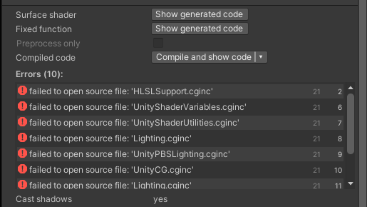
how do I turn this into an urp compatible shader?
Shader "Custom/Terrain"
{
    Properties
    {
        _MainTex ("Albedo (RGB)", 2D) = "white" {}
    }
    SubShader
    {
        Tags { "RenderType"="Opaque" }
        LOD 200

        CGPROGRAM
        // Physically based Standard lighting model, and enable shadows on all light types
        #pragma surface surf Standard fullforwardshadows

        // Use shader model 3.0 target, to get nicer looking lighting
        #pragma target 3.0

        sampler2D _MainTex;

        struct Input
        {
            float2 uv_MainTex;
        };

        float4 _StartCols[3];
        float4 _EndCols[3];

        void surf (Input IN, inout SurfaceOutputStandard o)
        {
            int colIndex = (int)IN.uv_MainTex.x;
            float t = IN.uv_MainTex.y;
            o.Albedo = lerp(_StartCols[colIndex],_EndCols[colIndex],t);
        }
        ENDCG
    }
    FallBack "Diffuse"
}
why not just use particles / vfx?
i cant, i need to find a way to use animated textures like these in unity
then you can just "offset" the texture as you suggested since it's equivalent of offsetting the UV, you may need to have a custom shader to ensure that the UV sampler is not set to "wrap" although you can probably manage if careful as is. You can use animator in Unity to animate the offset giving the same effect / function as in Blender
For the last example you linked either a flipbook or break it out into two which then you could use masking / UV offsets again. @midnight dagger
@dapper spade That first line (colIndex) probably isn't doing what you think/want.
But other than that, it's a really simple shader, use the lit master node.
and "just" recreate the logic using nodes. There's math nodes and a lerp node. IDK if you can pass an array to SG, but it doesn't look like that first line will do much anyway except maybe at the extreme right edge where UV.x would be 1 instead of 0 index value. You sure there isn't originally more math to that?
Anyway, you could always make the shader, and then edit the source (there's a view-generated source option somewhere depending on SG version it varies, they just changed it IIRC).
https://cdn.discordapp.com/attachments/497874081329184799/789653425205149747/effect.mp4
How can I implement it?
I have already implemented the animated highlight border using a shader.
I want to decorate and beautify it, I mean adding the distortion. Do I need a distortion image or function, uv distortion?
https://cdn.discordapp.com/attachments/497874081329184799/789652052316782636/unknown.png

Not used shader graph for a while - is there a node I can use to tidy something up? Like, a corner to just have a connection not take a direct route (like in ue4)
just so I can avoid having a line run straight across the middle of my graph, and instead go around the side
Newer versions (v10+) have an elbow (think right clicking a connection creates it or something?). For older versions, there's a Preview node which kinda helps (can collapse the preview to make it smaller)
elbow sounds great, but I guess I can't use it to maintain backwards compatibility
cheers cyan, good to know the future looks good at least 🙂
(I have to support 2019 LTS aswell)
Hmm not sure what happens to the elbow if you open the graph in an older version. (Oh right, it doesn't even open. Probably because the whole master stack changes).
- Is it possible to write to stencil only where my fragment shader returns more than 0.
- Is it possible to write two different stencil Ref values on the same sprite based on the frag's color (or do i have to use 2 sprite renderers for this), e.g. write stencil with the value 1 for the red parts of the sprite, and 2 for the blue parts of the sprite
You can do 1 if you use alpha clipping / discard on the pixels with 0 alpha.
You can't change the ref based on the fragment colour result though. Would have to use two sprites/shaders.
makes sense. Will the alpha clipping be based on my fragment shader or the input texture? Cause in my fragment shader I make some pixels complete transparent.
Depends on the shader. You can clip/discard based on any value, it doesn't have to come from a texture - but that's the usual way.
ah thanks i'll try out, i am new to stencils
what is object space, and what does it mean to go from object space to world space?
Object space is the coordinate system that has its origin in the center of the object. World space is the coordinate system that has its origin in the center of the world. @mint flax
You can convert between them. The center of an object has local space (0,0,0) but if that object is not in the world origin, that point has a world space coordinate that is different from (0,0,0)
So object space is measured relative to the object, world space is measured relative to the world
ah ok
I'm trying to write my own shaders and I'm just trying to figure out why when you try to render a cube before passing it to world space it shows as this box on your screen
whereas this is what it would look like
dont mind me, just doing shaders 101 :p
Is the terrain system better than using meshes for terrain, grass, trees, etc?
the terrain system is technically optimized for it's task, however you cannot do overhangs / tunnels with the unity terrain system. For that you need to use a separate mesh, grass and trees are separate to the terrain and are usually mesh's / billboards or a mixture depending on distance (LOD).
Depending on your situation, it's down to you to decide which is best to use.
for example if your scene is mostly indoors / cave system, then mesh is way to go.
If it's outdoors open world, the terrain system will probably be best choice, there is no hard fast rule I'm afraid 😉
you do what feels right for your project
Gotcha. Yeah it's open world with no caves, so I'll go with the terrain system then. Any ideas on how I can change the grass shader? Trying a bunch of things from googling, but if anyone has had any success with it in URP I'd appreciate some advice.
please help
https://youtu.be/KdILAO6KBY4

it works in the preview but not in the scene...i dont understand
Is this hacky? I have two materials that set all the same parameters and it should, except for one parameter.
So the only way I vary this unique property without having to manually sync the parameters for the two materials is via C#:
        image.material = Instantiate(image.material);
        image.material.SetInt("_Stencil", (int) stencilRef);
Cause I don't know how to inherit values of a material from another material.
Which approach should I take? Using Unity 2020
If you have a parameter that has a shared value across multiple materials, I would go with global attributes
ok thanks!
is there a way to set stencil for tmpro? I successfully did it for UI images, but my own materials on TMPro makes the text black and weird
i guess a quick way for me to do it is to modify the existing TMPro shader with the stencil stuff
Ah yeah I know nothing on stenciling
I think TMP exposes the stencil values on the material somewhere.
In the additional parts / debug or something
@rugged verge If the "Stencil Comp" is still a int field, it basically corresponds to the list here btw https://docs.unity3d.com/ScriptReference/Rendering.CompareFunction.html
(So Disabled would be 0, Never 1, Less 2, Equal 3, etc)
Should I try and find the grass shader, or should I just manually code my own billboard grass
yup I found it, I made enums on it so it's easier for me to set them via C# ( but i don't think it's possible on the Material inspector unless i modify the shader itself)
Hey everyone, I have a shader that has all the properties that the standard built-in shader but has vertex color support additionally. However objects that have this shader don't get affected by realtime lights. What kind of code should I add/change to make it work? Here are the cginc and shader codes:
https://pastebin.com/UUh00nCn
https://pastebin.com/qRRMJGa2
Pastebin
Pastebin.com is the number one paste tool since 2002. Pastebin is a website where you can store text online for a set period of time.
Pastebin
Pastebin.com is the number one paste tool since 2002. Pastebin is a website where you can store text online for a set period of time.
@hasty canopy I didn't check your shaders at all but to make a thing like that it would be just simpler to get the original shader for built-in and mod the vertex color for it. Each unity version has a shader source code pack for that specific version: https://unity3d.com/get-unity/download/archive (just navigate to the Unity version you use and click on the Downloads (Win) dropdown and pick Built in Shaders -option)
That makes sense, thanks for the idea.
However I know almost nothing about the shader codes so I don't know what to add exactly. Is there an easy way or a guide about vertex color codes or should I try to copy paste everything that has the word vertex in it?
My Text Mesh text is looking blurry on my Render Texture which is on a shader. Does anyone know how to fix?
@fringe pagoda I dont know if you have the same settings as i'm in HDRP, but mine give a pretty decent result at these settings, you could always try increasing the depth buffer, or color format, not sure:
got it thx
have any of you guys tried the new 2020.2 shader features yet? I'd love to build a shader that can go to both HDRP and URP but so far I've tried it has not given me both pipelines as a target

In this video, we'll show you a demo of the new Shader Graph updates in Unity 2020.2, which makes it much easier to create graphs that work in both the Universal Render Pipeline (URP) and the High Definition Render Pipeline (HDRP). We also show you how to use the new Graph Inspector and the Master Stack output, and discuss project upgrade consid...
it's showcased here but I don't seem to have it in 2020.2
Do you have the HDRP package installed? That's probably a requirement to get it to appear in the targets list
oh? you need to have both render pipelines active in your project somehow? I've never worked like that before
I don't think they both have to be "active", but it probably does need to be installed
I'll go try some things and see if I can figure it out, thanks for pointing me in the right direction
or in a direction at least lol
@regal stag yep, thank you!
Hello i copied existing shader and changed its name and it resulted in errors
how is this even happening cus the code is pretty much the same except name?
@grand jolt you might want to try and click on it and click 'reimport'
For some reason I believe my Shader Graph is missing a ton of things.
I can no longer set default values on my properties. The Cog Wheel thing is missing. A 'Lit' Material no longer has a heightmap input, etc. I did discover the Graph Inspector thing, but it doesn't have the cog wheel options to enable a heightmap, etc.
Newest Unity HDRP btw
You might be able to right-click in the fragment part and add additional things? I haven't used the master stack in HDRP so not too sure, but that would be my best guess if it's not an option in the graph inspector.
As for editing values on properties, I think you have to select the property then look at the "Node Settings" tab at the top of the graph inspector. (I'm not a fan of this change so hoping it's reverted tbh)
Ahhh I see, I had to right click the tiny blue strip things to add a node to it. Interesting... And yeah you were right about the node settings part. Kinda weird they went that route. I'm sure they had their reasons though.
But i'm not seeing either a height or displacement. So not sure what else it would be called lol
if this isnt the right place for this question, let me know and ill remove this, but I was wondering if theres a guide online or something on how I could make a custom path tracing shader or something? I have made one in shadertoy, but I have no idea how to port it into unity well, and I wanna try and make it use wiremeshes instead of just SDF's, but I dont know how I can have the shader access all the polygons of the meshto calculate ray bouncing
if you have the shader in shadertoy then watch this tutorial to convert it to hlsl (note : you might want to be careful with the passes if you are using URP/HDRP)
to access the geometry you can use the UVs and vertes in the functions .
The tutorial :
https://youtu.be/CzORVWFvZ28

Twitter: @The_ArtOfCode
Facebook: https://www.facebook.com/groups/theartofcode/
Patreon: https://www.patreon.com/TheArtOfCode
PayPal Donation: https://paypal.me/theartofcode
Ever wondered how to get a shader from ShaderToy imported into Unity? Well wonder no longer because in this video I will explain how to do it. Its really not that hard.
Ru...
@lean lotus 👆
ive done that but I dont know how to adapt it to being able to use wiremeshes or feed the resulting textures back into the input to be further refined
The resulting UV value passed by the vertex shader to the fragment is already the proper interpolated UV between the 3 vertices of that triangle based on the fragment position in that triangle.
If you don't have a lot experience with the unity shaders then it's hard for me to explain
I understand that I think, but if it say bounces 7 times, that would be 7 different objects that it needs access to, is that something I can do?
Yes but you will need to have a master shader and a shader for each object so you can pass the data
oh heck ok thx
heck, is there any better way/tutorial of how I could make a path tracer in unity?
Are there any complete courses on shaders? I want to learn but I'm a complete noob
I am hoping to create a dynamic brush stroke effect and there are many ways to approach it. I had an idea and wanted to know if it was feasible. Could I use a dotted texture on an object, sample the screen-coords of those dots, and feed those coords to an array for the line renderer to use?
sounds like a complicated way to approach it, do you have an example image of what your trying to achieve?
Trying to recreate this style with an unlit shader. I’ve been discussing it with a few others in some other discords.
The typical approach would be to use several brushstroke textures and cycle/animate through them. But I worry that makes the strokes look unintentional/disconnected from the subject they are shading. It ends up just looking like a cropped texture
Source at normal speed: https://youtu.be/AWEm4tA2hMc
I was inspired to iterate on this after seeing @desert hare’s experiment
https://twitter.com/ImPACIOble/status/1327810057929588736?s=20

This week in Saturday Shader experiments, yet another handrawn shader done in shadergraph, this time inspired the the ED to #JujutsuKaisen. #unity3d #screenshotsaturday #indiedev https://t.co/NdomVHHcLR
his description makes sense but it will limit how much outside of the objects are it will flow, the only way imo to get a longer less clipped looking brush stroke is to do it as a post processing effect
I was wondering if I could fill/paint a render texture using data sampled from the depth texture (thinking of the color threshold approach used in outline shaders).
It’s an unusual challenge. Because you simultaneously want the strokes to relate to what they are shading, but you don’t want them limited by the bounds of the mesh 🤔
There's a few examples around, with solid ideas which imo could be tweaked to get the style your after this post explains one quite well https://gpuhacks.wordpress.com/2012/01/30/brush-strokes/

Recently I’ve done some work on non-photorealistic rendering for a pet project of mine. For starters, I wanted to get an “artistic” look as a real-time post-processing effect, som…
it's basically using a brush texture, which depending on the texture used defines your style
Oooo I haven’t come across this before. Most posts I’ve found use a kuwahara filter which I’ve avoided since it is a subtractive smoothing filter
you would need to add outline render / pencil lines back in / overtop though
so it might not be cheap
looking at the example you gave, you could probably skip aligning with tangents for brush strokes and just apply some accross the whole screen then blend with scene color 🤔 might work
Yes, luckily the visual style I’m after isn’t too concerned with depth/ambient lighting
All unlit solid colors
I was thinking I could add a trail renderer at specific points on the object to mimic the strokes during quick motions
Thanks for your help. I’ll take a look at this more tomorrow
well it's some food for thought, good luck 😉
You've hit on the heart of the issue. Per-mesh things are per-mesh! 😉 But you have a "back buffer" for things like color, and depending on pipeline and implementation, also surface normals. But you won't have material attributes (like reflectivity) unless you store them yourself in yet another set of screnn-space buffers .
Then there's the "What about off-screen stuff?" question. This comes up in all ray-tracing, including the new RTX-type API's. So a puddle on the ground has to reflect trees/sky that isn't on the screen!
There's no simple answer, and what you're asking to do is quite complex. That's why SDF's and such are in a way much easier since you can "just" go find out what's in the scene for any ray since the entire scene is described IN THE SHADER. But with meshes, they only exist on the C#/CPU side unless you do something special like create buffers for your scene on the GPU. But you'd have to literally upload your entire "world" of meshes AND materials to the GPU, rather than just the frustum-culled bits.
In the end, it's not a simple thing you're asking to do.
I'd try, just as like @hearty stump said, converting the SDF shader first. To do that you treat it like a full-screen post-process:
- In C# you'd create a full-screen quad.
- call a DrawMesh() or variant directly rather than using a game object to draw for you. Passing the ShaderToyish material with its shader and parameters like camera view direction and camera position (Unity has these already if you find the shader variables)
- In the shader, the frag() function would do per-pixel calculations using your current SDF's. But what you CAN do is overlay anything that's already there! <== Important.
So you can have a "mix" of ray-traced things and mesh-things easily, with limitations. Passes for reflections and shadows will be a problem, but you can at least clip to the depth-buffer and not draw an occluded pixel, for example.
:2cents:
Hey guys. I need help with UI shader. I wrote a dissolve UI shader, but how can I apply it to all the child nodes?
I tried to add a Mask, but it breaks the dissolve -- when I apply the dissolve material in runtime nothing happens.
How are you doing it, show yur code
hey guys I am using this shader https://gist.github.com/TarasOsiris/e0e6e6c3b8fdb0d8074b
but if applied to cube for testing purpose. except one side, every other side seems to be see through. Any idea how can I make it opaque

Gist
Flow Map Shader for Unity3D. Used with Sprites. GitHub Gist: instantly share code, notes, and snippets.
the one opaque side
Do you expect it to be transparent or opaque shader ?
Opaque like this
I want all sides to be opaque

The video of issue
Here are the changes to make it opaque :
line 18 : "Queue"="Geometry"
line 20 : "RenderType"="Opaque"
line 25 : Cull Back
line 27 : ZWrite On
a line 28 : Blend Off
Could also maybe be a good idea to add ZTest LEqual
What it exactly does?
Depth testing
I am trying to achieve this kind of texture on weapon in cod https://youtu.be/KXV5DgpV0TY?t=280

NEW EASTER EGG SOLVED IN COLD WAR ZOMBIES DIE MASCHINE - DAY ONE MYSTERY SOLVED!
►Go show GlitchingQueen some love for solving this mystery: https://www.youtube.com/user/mountainbikingrulz
►Get 30% off with code Dalek on Gfuel NOW until 14/12 - https://gfuel.ly/2GEr2Jf
In this video, I'm showing you how to get a free max ammo on Cold War Zombie...
Anyone?
@void sable What happens if you put the dissolve material on a child object, what does it do?
are arrays of vector2 not blittable?
tried sending an array of vector2 to a shader via computeBuffer
It applies it, but I can't change the uniforms
it seems that Mask blocks the material updating
uniforms? can you be more precise
oh okay, yeah properties is what I know 😄 do you like get all the materials in children somehow? are you altering just one for now?
I have a root object with Image component on it. It has a custom script, which applies the Dissolve component on itself. Dissolve component applies dissolve material for Image component, which changes the rate variable of Dissolve shader over time (object is dissolving).
Root object has a few child objects, which are panels and images. I want them to dissolve too using mask. But mask blocks my dissolve material from changing and updating correctly.
Why using mask?
But if I will be changing material in editor, every time I apply new material to my root object, it updates it properties, so the dissolve effect works
if you just use the same dissolve values
What are the other ways here?
If the material is on the child image, it should just use the values in the material set, right
What same values? I have the dissolve material only on 1 component, not all of them
Yeah, thats what I was asking, if you can set the material to all of them
I can't. Children has their own materials and effect, there are also text components which should dissolve too, they have their materials too
ohhh well, thats some hard thing to do then, cause you rmaterial will only work on the renderer it is (Image is basically also a renderer based on some 2D thing)
So what happens if you mask the image with the dissolve material, the masked images will just stay full renderer?
Can somebody explain to me why
_MeshRenderer.sharedMaterial.SetColor("_BaseColor", Color.magenta);
still causes Unity to create a new Instance of my material? Is there a way to set new colors by code without creating an instance?
Color magenta will create a new material with that color
Oh but it should not, you are right, as it is shared
I thought the whole idea of the sharedMaterial was to prevent Unity from creating new materials and change the properties of the exiting material (at least that was the case with the legacy render pipeline).
@void sable So, you're using this UI mask, right ?https://docs.unity3d.com/Packages/com.unity.ugui@1.0/manual/script-Mask.html
I think you will maybe need to add a specific mask pass to your shader, to write into the stencil bit mentioned at the bottom of the page ?
It shouldn't. Are you sure you're not calling .material somewhere else ?
@hollow swift I guess it has to create like a copy of the material that is shared anywayy with the new color, at least once? Or does it happen more than once?
No, they will be masked too according to the parent dissolve. But the material is not being updated (it applies only once and then stop updating the uniforms) and also I loose all the color effect (dissolve has a border) for all children objects.
99%, I checked both scripts that influence the MeshRenderer
@void sable can you show an image or short clip of it?
Yup, have the stencil id set already
This is the screenshot of applied material for my object. Here you can see white (root image with the material) which has borders, next you can see red and green, which are children. They don't have border.
The problem is not with the border right now. The problem is, that material it not being rendered with updated properties. Mask (?) saves the initial properties of material when I instantiate it, and then ignores all the updates which I am doing in Update function
dissolveMaterial.SetFloat("_Level", rate);
like, get material temporarily, set the stuff and put it back on the renderer updated @void sable
Looks like I have to do it every frame, which is stupid and costly
I'll check
@void sable but it should be working with properties, tbh... are you setting the properties of a shader graph like shader?
No, it's legacy RP, it's a written shader
Btw I found the way it works. but it's stupid
If I recreate a new material instance every frame, change it's properties and assign it, it will change
oh okay... might thinking upgrading to shadergraph to use the properties stuff, but I am not sure if legacy has that too anways.
"legacy" shader properties @digital gust : https://docs.unity3d.com/Manual/SL-Properties.html

Nothing special here
@amber saffron cool, thanks for updating me there, just jumped into shaders with shader graph 🙂
This seems ... wrong ....
Maybe because of the UI system ? Have you tried with material property block ?
Okay, I got another workaround. Every frame I change material to null and then assign my material again.
image.material = null; image.material = dissolveMaterial;
Also I have a custom Image script which overrides GetModifiedMaterial (https://support.unity.com/hc/en-us/articles/115001681783-Passing-shader-parameters-by-scripting-on-masked-GameObjects), so I can change material properties after the mask. That works, but I still have 2 problems.
- It's still a hack and a workaround.
- Image effect (borders) is applied only for parent object, because Mask works like...Mask, and it seems that I have to use something different (I still don't understand how to apply material to all my children, CanvasGroup maybe?)
Unity
Symptoms
The shader behaves as expected in most cases, but when used with a masked UI component, the values from SetColorArray/SetColor/Set* are not being passed through to the shader.
The sh...
Did you check the canvas renderer stuff, maybe this gives you some rendering options? Just a blind guess here
No, I didn't. But it won't help with the 2 issue
Yeah, maybe I can use canvas for each object, and then apply the material for canvas renderer
But, I mean, every object in my game is a card. So there will be a lot of them. Is it good to put them in separate canvases?
Yeah, but it works only for 1 object. So no difference between image material or canvas renderer material
Okay, can you reset this conversation once, so what is working and what is not besides the hack workaround issue 😉
Hack is working, but only in terms of "dissolve all the children too", effects are not visible on children (because mask do masking, it does not preserve color).
Other stuff does not work
So initially mask is not a good idea, I think
I just thought, cant you just mask with the shader you have? Without using the extra mask on UI?
I can, If I find a way to apply shader to children too
What shaders would I use for my mobile game's color materials?
@void sable The children have their own materials, you said, so they have their own shaders too. So you cant really put them there, you either have to make a copy of your shader or overwrite with material instead of sharedmaterial, I guess
anyone knows why my shader turn off
post processing
on second camera
it only works for first camera
Do you have to like create two separate postprocess layers/renderers?
wut
also thing is it also happens if i remove first camera before launching second
so technically there should be only one camera
seems i cached the old camera somewhere? or something like that
what you mean
oh the person i copied this script from doesnt use 2 cameras
he just teleports his camera
to make it work
i need help with the creation of avatars with blendshapes. i was wondering whats the best way for make a avatar creator for a online game similar to Star Wars Galaxies, where you have 3 body forms for the character lets say we can add muscle and then we can change weight on the character and make it more fat or thin so i have to mix muscle body shape and thin fat body shape with the normal one, but i want to GPU Instance my characters so i can have alot of them like Star wars galaxies have... this game im try to recreate its very old ,like from 2002, so im wondering if unity has archieve something similar and if its related to shader or not im not sure but i need help, anyone have any hint around "GPU INSTANCING SKIN MESH RENDERERS WITH BLENDSHAPES "? thanks
I'd like to make a shader that makes any given sprite white (except for the areas with an alpha of 0). I would assume that would be quite simple, but I'm not the best with shaders. Any ideas on how to pull that off?
@sinful ledge you can go with an Unlit shader using shader graph and use the UV node the conecet it into a split not to get the different channels RGBA and the rest is just to multiply the RGB with with color and alpha will just be cobined with the RGB and then conecet it to the color in the master node
I have a complex shader that is using 28 temp registers. Where can I read up on how to reduce that number?
I did a cursory check on the compiled code, and it seems like every field(xyzw) of every register is being used.
hey for a SDF driven path tracer in unity, is there a good way to easily make more compicated scenes then bit by bit making them all in the origional shader file?(like how you can just drag in a mesh for some stuff, but for SDF's)
also how does unity do its path tracing and ray tracing that I think is built in? I really want to create my own ray/path tracer in unity but am strugglin
also also, how do you feed back in the resulting image from a path tracer back into it as a texture for path tracing that does multiple passes to converge?(I have it made in shadertoy, but idk how to feed back in a resulting texture back into a shader in unity)
@hearty stump Thanks for you response. Sorry for being inexperienced with shaders, but I must've messed something up. Heres the shader graph:
thank you for this! ill have to think about it, but what do you mean by "But what you CAN do is overlay anything thats already there!" in the third thing you gave?
@sinful ledge multiple with a color node you forgot this the combination will be after you have multiplied the RGB with a color the combin it again with the alpha
You could do this with the Sample Texture 2D node to sample your sprite texture (using the _MainTex property). Drag the alpha (A) output of that into the W/A input of a Vector4 node (or Combine node), leaving the X, Y and Z inputs as 1. That can then go into the Color input on one of the Sprite Master nodes
Thanks for your input. I thought that would work but it doesn't seem to - it doesnt seem to recognize the alpha:
Without shader
with shader
@sinful ledge The Unlit Master node alpha is a separate input. If you're using 2D sprites you'd usually use the "Sprite Unlit Master" instead though.
If you want to stick with the regular unlit one, you'd have to put the A output into that Alpha instead, and change it to Transparent surface mode using the small cog on the master node.
Ah I figured it out. I'm using the 2d renderer with ldrp so I used the above graph with the Sprite Unlit Graph (Expriemental) Shader
Thanks for your help!
I am new to the concept of shaders and shader graphs so bear with me. I am trying to draw a circle on a unity terrain when I move on it with my mouse (like a pointer). I know that I can control variables in Shadergraph via script but I guess I am missing a piece of the puzzle here. The following picture is my shader graph but when I apply this shader to a material and the material to my terrain I see a static ellipse (circle). Although I would expect that my position node in the bottom of the graph would control the alpha (and therefore visibility) of my ellipse. If someone could point me in the right direction that would be helpfull. I did see many surface shader script tutorials that do what I want but as far as I know this is not supported by URP which I am using.
@floral fulcrum I don't see anything that would move the ellipse around
only the alpha channel's "circle" moves around
what you can do is pass in: (wpos-mousepos).xz into the ellipse's uv
Thanks for the tip. I guess I misunderstood the concept of the position in shadergraph. I will see if I can make that work.
There is some raymarching sdf plugins on the asset store, if you look at how they work UX wise, you can place objects in the scene hierarchy.
I guess you can make a script that looks into the scene hierarchy for specific object types, and if will build the required SDF representation of the scene in a single shader (could if be vertex/frag, or compute).
For how the built-in path/ray tracing is done (in HDRP), it's using dedicated shader passes for raytracing, using DXR api
@cosmic prairie I got it to work. Thanks for your help!
I'm trying to modify a water shader that was written in shaderforge, and I'm having two issues. The first issue is that in VRChat and in the camera view, but not in the scene view, I get white pixels around the edges of objects and avatars. Normally I'd assume this was some issue with antialiasing producing partially transparent pixels around the edges, but clearly that isn't the case because VRChat doesn't have that, and Unity doesn't have it in scene either unless it's enabled on the main camera, which it's not here.
You can see the effect around the edge of the buoy, and the boat. I know it has something to do with the depth buffer, because the effect renders foam around objects using the depth blend node. I tried changing the depth test in shader forge's settings from <= to < but this had no effect. Pictured here are what I believe are the relevant nodes.
The other issue I'm having is when I look at the source, I can see it's doing a grabpass, and I've already removed the nodes that calculate underwater distortion, and there is no longer a screen color node, which I assumed was what created the need for a grabpass. Not sure if removing the name of the grabpass texture if what I need to do to get it to remove that code or not, but I guess I'll try that next.
Oh, and I can't use the latest version of Unity or its shader editor because VRChat is a few versions behind.
I'm thinking I will likely be UVing my brush textures a lot but I thought I'd share this paper that goes over many Stroke-based rendering techniques and addresses how it is difficult to capture "loose and sketchiness" or randomness (on page 24)
https://www.cs.ucdavis.edu/~ma/SIGGRAPH02/course23/notes/S02c23_3.pdf
https://tspace.library.utoronto.ca/bitstream/1807/16888/1/Hertzmann_574_418.pdf
In general it is a really useful resource. Also my initial whacky line renderer idea is somewhat similar to a proposal they make in the paper:
PAINTERLY RENDERING WITH LONG, CURVED STROKES
This method can be extended to use long, continuous curves instead of short strokes. In my system, I limit brush strokes to constant color (Section5.1), and use image gradients to guide stroke placement. The idea is that the strokes will represent isocontours of the image with roughly constant color. Our method is to place control points for the curve by following the normal of the gradient direction. When the color of the stroke is further from the target color in the reference image than the painting, the stroke ends at that control point.A more detailed explanation of the algorithm follows. The spline placement algorithm begins at a given point in the image p0, with a given a brush radius R. The stroke is represented as a list of control points, a color, and a brush radius. Points are represented as floating point values in image coordinates. The control point p0 is added to the spline, and the color of the reference image at p0 is used as the color of the spline.
You can render everything "normally" and then render in ray-traced SDF stuff into the scene "on top" of that, clipping to the depth buffer. The trick is things like reflections, which is something you're probably after. You could look up "Screen space reflections" and see if you can figure something out to hack in an SDF type of thing.
Or just use Screen Space Reflections and skip raytracing the actual objects. But I'm unsure about shadow processing, you might have to hack up some kind of updates to shadow mapping too.
It gets complicated fast, and I have only done SDF's inside simple-lit stuff, without reflections/shadows/etc. So research is your friend, and you've been warned. 😉
ok thx, trying to in the end get the global illumination I get in my shadertoypath tracer
https://cdn.discordapp.com/attachments/497874081329184799/789653425205149747/effect.mp4
How can I implement it?
I have already implemented the animated highlight border using a shader.
I want to decorate and beautify it, I mean adding the distortion. Do I need a distortion image or function, uv distortion?
https://cdn.discordapp.com/attachments/497874081329184799/789652052316782636/unknown.png
@lean lotus Even the fastest cards on the (mainstream) desktop ATM don't fully ray-trace GI, they all cheat and also use AI to fill in the gaps.
If you want to actually fully ray-trace a scene, you probably don't want to do real-time-graphics. Hollywood does that, look up things like "Renderman" IIRC. But they spend minutes using render farms to render one frame fully lit in hi-res detail.
YMMV
I know, im not looking at real time for pathtracing
With "real" ray-tracing, you get things like "free" shadows and stuff.
So sure, if you don't care about realtime, have at it. In that case, I'd say you'd have a scene, and a set of render targets:
Like the Depth Buffer ideally with surface normals.
Color Buffer.
Probably a materials buffer.
But IDK about things like..."How do I handle off-screen stuff?"
Maybe you can cheat and do at least 4 camera views from various directions and then interpolate/extrapolate.
Then pixel shaders for all these things would "fill in" the buffers, and THEN, you could pass the whole thing over, bounding light rays and using compute buffers for various light info and such, for minutes (hours?) calcing all this stuff.
There's versions and examples on ShaderToy and "Ray Tracing in a Weekend" type of things, but most of those are using SDF's and such as we've discussed.
I've not really tried it (as you can probably tell) so I just was interested in the discussion.
It's a neat idea, but won't happen in real-time very well at all, IMO. But check into the RTX level stuff, as that's cutting-edge and probably the most up to date (and requires hardware support).
how do I turn this into an urp compatible shader?
Shader "Custom/Terrain"
{
    Properties
    {
        _MainTex ("Albedo (RGB)", 2D) = "white" {}
    }
    SubShader
    {
        Tags { "RenderType"="Opaque" }
        LOD 200

        CGPROGRAM
        // Physically based Standard lighting model, and enable shadows on all light types
        #pragma surface surf Standard fullforwardshadows

        // Use shader model 3.0 target, to get nicer looking lighting
        #pragma target 3.0

        sampler2D _MainTex;

        struct Input
        {
            float2 uv_MainTex;
        };

        float4 _StartCols[3];
        float4 _EndCols[3];

        void surf (Input IN, inout SurfaceOutputStandard o)
        {
            int colIndex = (int)IN.uv_MainTex.x;
            float t = IN.uv_MainTex.y;
            o.Albedo = lerp(_StartCols[colIndex],_EndCols[colIndex],t);
        }
        ENDCG
    }
    FallBack "Diffuse"
}
Hello, so i have a problem with this shaders draw order. Sometimes objects with this shader draw in front and sometimes behind other objects. And now sometimes it decides to net render at all. If anyone has any suggestions please let me know.
Shader "CustomShaders/StencilMask"
{
    Properties
    {
        LocalStencilNumber("StencilNumber", int) = 0
    }

    SubShader
    {
        Tags { }

        ZWrite Off
        ColorMask 0

        Stencil
        {
            Ref[LocalStencilNumber]
            Comp Always
            Pass Replace
        }

        Pass
        {

        }
    }
}
so there is no way to modify the UVs in the vertex shader of a Shader Graph. I thought maybe i could stuff them into the Tangent coords since I don't need them, but that ends up getting transformed before it gets to the frag shader. anyone know any other workarounds to modify UVs in shader graph? (it has to be in the vertex shader so its properly interpolated in the frag shader)
Hello, I do not know much about shaders, but I want to know if this effect is possible using a shader? I know a similar effect could be likely be created using multiple cameras and layers, but I feel that there is a more simple solution to creating a kind of chroma keyed effect with a texture background, let me know if you have any ideas.
@fading sable this is just a view related texture put on top of the object. You should be able to just use the position node or camera node to feed the uvs of your texture.
very simple effect, no fancy chroma key needed if you know which objects will need this effect on them
I already answered that. What's the issue?
@topaz marsh Try changing the queue to something above the other objects so they get drawn first. IDK what render queue you're using for this stencil pass. You can also try Ztest LEqual The z-test (depth buffer) is different from the stencil test. But the default is already that, so....not sure.
I'm still not sure what to do
I'm not sure that the text shader is working, first off, since that first calc doesn't make a ton of sense.
But otherwise, I guess, someone can convert it to a Shader Graph pic for you, I just don't have time right now, maybe later.
whats a good basic shader to make for a noob at shaders?
Like written code or shader graph?
shadergraph
Oh, just make right click Shader - PBR Graph and double click. Your editor will open, press space or right click in it and create nodes. Play around with it a bit.
Its fun to just doodle all nodes together, see what happens in your 3d object. Be sure to make a material and select the shader from Shadergraphs->Your Shader name
THere are tons of tutorials about it
I saw a video that mentions that material emissions can cast light/shadow in 2020.2. Anyone know how to go about that? Can't find much about it, other than it being mentioned in a video.
Did you just try to put an emission somewhere and check lighting and shadows?
@digital gust Yeah, that's what I usually would do for an emitting material, but ofc that does not create real light. I'm asking before I'm not sure what process to go through to enable real lighting.
Afaik it should just emit light into the scene with the right render pipeline selected. Not sure about 2020 if it needs HDRP or URP or standard
I'll give that a try.
Currently the shader is using the default "geometry" render queue and when I tried to change it it either started to draw under everything or above everything witch is not what I want
OK, but that shader pass that you showed is "just" the stencil pass. Then there would be another pass or another shader somewhere that draws stuff based on the stencil settings. I'm surprised it's drawing anything, above, below, or whatever.
Is that the full shader? Do you have multiple materials on the object?
@topaz marsh
Hi guys, I'm having troubles with vertex displacement inside a shader graph.
I'm offsetting the Y to solve some z-fighting with a decal, but now the seams are visibile.
Any suggestion on how to fix it inside the shader?
Here is a shader i use for everything else
StencilNumber I set this to 0, 1 or 2 depending on witch camera is rendering through Shader.SetGlobalInt (i do it in OnPreCull for the camera)
Shader "CustomShaders/DefaultShader"
{
    Properties
    {
        _MainTex("Texture", 2D) = "white" { }
        _Color ("Color", Color) = (1, 1, 1, 1)
        _BumpMap("Bump Map", 2D) = "bump" {}
    }

    SubShader
    {
        Tags { "RenderType" = "Opaque" "Queue" = "Geometry" }

        //Cull Off <-- makes shadows go oof

        Stencil
        {
            Ref [StencilNumber]
            Comp Equal
            Pass Keep
        }

        CGPROGRAM
        //#pragma surface SurfaceFunction Lambert keepalpha addshadow <-- if shadows go oof
        #pragma surface SurfaceFunction Lambert

        struct Input
        {
            float2 uv_MainTex;
            float2 uv_BumpMap;
            float3 worldPos;
        };

        sampler2D _MainTex;
        fixed4 _Color;
        sampler2D _BumpMap;

        float3 sliceCenter;
        float3 sliceNormal;

        void SurfaceFunction(Input IN, inout SurfaceOutput Output)
        {
            float sliceSide = dot(sliceNormal, IN.worldPos - sliceCenter);
            clip(-sliceSide);

            Output.Albedo = tex2D(_MainTex, IN.uv_MainTex).rgb * _Color;   // base (diffuse or specular) color
            Output.Normal = UnpackNormal(tex2D(_BumpMap, IN.uv_MainTex));   // tangent space normal, if written
        }
        ENDCG
    }

    Fallback "Diffuse"
}
PS dont think about the comments
I set my decals to cutout rather than transparent, this solved z fighting for me
I see, is this something I can set with shader graph?
yes it's simply the opaque setting and adjust alpha clip to 0.6 although I find mine needed 0.8 to look good but I'm just noob in training 😉
OK, first off you're using a surface shader, I'd try vert/frag if it was me.
But OK, so then, since you're using a stencil in another shader you'll want readMask and writeMask otherwise you're not going to get what you expect...unity uses many of the bits in the stencil mask for its own purposes, and that might be part of what's messing you up.
Also, IDK why you're stenciling on pre-cull, as that's going to have to process basically your entire world, so I'd change that one to something culled. And each camera probably has it's own stencil buffer anyway, but I'm not sure. However, it's basically its own pass as it is.
So I'm really confused as to what you're pulling off, but I'm not being critical at all.
See the part below about deferred rendering path for more occasions to weep:
https://docs.unity3d.com/Manual/SL-Stencil.html
But as you can see, lighting calcs and stuff are going to screw your stencil, particularly between cameras, and varies depending on deferred vs forward.
You want 2 bits for your 3 values, if you want to know what camera rendered what pixel. Somehow.
That's kind of tricky.
@topaz marsh
Also see post by bgolus here:
https://forum.unity.com/threads/stencils-surface-shader.417700/

Unity Forum
Can't get stencils to work with surface shaders. Works just fine with fragment shader.
Trying to create a very simple mask that just writes into...
sooo somethings gone wrong in my conversion from shadertoy to unity, on shadertoy my pathtracer is fine, but in unity, its all black except for a sphere that I have set to emmisive
heightMapCompute.SetBuffer(0, "vertices", vertexBuffer);
i get error here
Kernel index (0) out of range
so basically its about first argument of .SetBuffer
the error only happens in webgl version
(Filename: Line: 218)
@lean lotus Sounds like a lighting problem....AKA...computing light position and resulting color. Guessing. Otherwise some weird math is returning a zero/null somewhere and you get black (0,0,0). Try a simple shading using white (1,1,1) * N dot L just hard coded. And then backtrack from there.
2 cents.
@grand jolt That last one is trying to execute a compute shader, first one probably is too. That's code, not data, so you don't want to do "setbuffer" on it. It's invoking a compute kernel. Check your object references.
Or check for unity bugs, or not-allocated buffers or something weird.
i think it just doesnt see the shader?
these are the same ones i just added findkernel to it
I'm a little confused by how SDFs differ from say, a silhouette mask using the depth buffer. Also are SDFs only relevant for photorealistic rendering or do they have uses for NPR shaders?
btw this only doesnt work in WEBGL
My friend made me a shader, it works great in the shader graph but when put on a material it doesn't do anything, just solid black. I can't put the textures he provided into here either. Its just grayed out
anyone know a fix for this?
It doesn't work on any material
hi friends
i imported a .fbx into Unity
i applied the materials but it shows pink
im gonna sleep for now, if anyone has a solution, can you dm or ping me?
thank you, have a good night
are you sure the material is appliied?
If you are using URP or some scriptable rendering pipeline, make sure to upgrade the shaders/materials
Also, it says that assetimporter is referencing assets from previous import, you might want to delete all the prev import data and re-import
Can't say anything with this image. You need to open the shader graph and show the connections, maybe?
I fixed it, I just had to press save asset for some reason importing it undid that
i think webgl doesnt support Compute Shader does it
hi guys,
i have this render-texture that renders 2 circle like the picture below.
the circle has e little blur / glow near the edge of the circle (opacity not 1).
what i want to do is make that blur / glow a solid and has the same color as the center of each circle via shader.
so i already made a shader that sample the render-texture and do a step operation so that i can get the blur / glow part of the render-texture to a solid white color like the picture below.
now how do i color the blur / glow part that i already made solid to be the same color as the center of each circle?
folks, I have created a custom shader in the shader graph for the wind sway effect and it works fine however it makes the object disappear at certain angles. I guess my shader trigger culling by mistake. Any idea what to look for in the shader graph to find the root of this?
this is tricky as the mask you have created as effectively a pp effect which does not know what color it should be, is this for mobile platform? if not there are probably some better solutions
yes this is for mobile,
what i can think of right now is to use another camera (i call it blurColorCamera) that only render a circle with solid color with the size of the blur / glow circle.
and i can change the blur color by sampling the renderTexture from blurColorCamera.
but i don't think the performance will be good as i use 3 camera
- camera 1 : render environment, UI, etc
- camera 2 : render the circle with blur
- camera 3 : render the circle with solid color (the size is the same as the circle with blur)
all fixed
if it's just circles you could oversize them slightly and use shader to create soft edges and harden them. define the circle in the shader with maths to enable smaller diameter than actual object. if that makes sense, then you can pass variables over to control softness of edge / fake blur.
I suggest this because doing a blur on mobile is costly
sorry, i'm pretty new with shader.
i get what you're saying, but i don't know how to create the soft edges without using a blur.
are there any specific keyword that i can use to do a research on?
what i can think of right now is to use some 2d sprite smooth outline shader
I notice that your initial image says "mataball" on bottom, is this your final intentions? if so It would probably be better to research that line of thinking as it will yield different results and should not need camera stacking
Can anyone point me in the right direction for, say, making a dissolve PBR graph that only dissolves within a radius from a Vector3 point? I can't figure out how shaders + world space positions work.
Use the distance node to compare the world space position (that you get with the position node) to your define vector3 position
Then it's up to you to alter this distance to find the threshold value for the dissolve
Any clue how I could also have multiple points? I have heard array properties are not supported
For the moment it's not supported by shadergraph, but I think you can hack it using the custom function node. It requires writing a bit of code :/
Can't ya just get rid of the glow in the first place?
I mean, the fastest effect you can have is the one that does it right the first time (particularly on mobile).
Instead of trying to pass again and fix it later...
I still cant get my path tracer that I tried to port from shadertoy to output anything but the scene I gave it, but its all black except for an emmissive sphere in the center
what would be a good way to debug this/to do from here?
My ultimate goal would be to make a custom path tracer in unity or something, but im being more and more convinced that its not something I am able to do really
@lean lotus i think it would require writing a unity rendering plugin, which is not something you want to do
is it?
DXR supports pathtracing. look at the HDRP package
Hello. Is there anything that shader graph does not do, so people choose using writing own code? Or learning shader graph solves lots of problem ?
@limber fossil using shader graph helps you make stuff that works for both HDRP and URP
why people keep using "writing code" still?
and is there any cross platform solutuon for graph way?
i think that's the idea, yes
currently you can't use Shader Graph with Graphics.DrawProcedural
that's one limitation
if you are drawing geometry generated in a compute shader
another kind of obscure Shader Graph limitation that i ran into was that you cannot modify UVs at the vertex shader stage
thank you for information!
I wish we had a program runs for get the graps into code, so we could use it. thanks !!!
Is it possible to use a compute shader without actually creating a compute shader script?
I.e. just creating a CS script where I define a ComputeBuffer and then just send it directly to the material?
using UnityEngine;

public class SimplePointCloudGen : MonoBehaviour
{
    public Material material;
    protected int number = 20000;
    protected ComputeBuffer compute_buffer;

    struct Point
    {
        public Vector3 position;
    }

    void Start()
    {
        compute_buffer = new ComputeBuffer(number, sizeof(float) * 3, ComputeBufferType.Default);
        Point[] cloud = new Point[number];
        for (uint i = 0; i < number; ++i)
        {
            cloud[i] = new Point();
            cloud[i].position = new Vector3();
            cloud[i].position.x = Random.Range(-20.0f, 20.0f);
            cloud[i].position.y = Random.Range(-20.0f, 20.0f);
            cloud[i].position.z = Random.Range(-20.0f, 20.0f);
        }
        compute_buffer.SetData(cloud);
    }

    void OnPostRender()
    {
        material.SetPass(0);
        material.SetBuffer("cloud", compute_buffer);
        Graphics.DrawProceduralNow(MeshTopology.Points, number, 1);
    }

    void OnDestroy()
    {
        compute_buffer.Release();
    }
}
Does anyone know why this is not working?
I'm trying to draw point clouds, but nothing is showing up
I have a feeling it has something to do with DrawProceduralNow
sorry for the late response,
yes it's for a metaball, and you're right, i'll research more about metaball rather than using a hacky way
thanks again
Need some help with shaders
I need to expand the cube curved sideways like the one below
https://www.youtube.com/watch?v=cX7mDteQr5Q

Showbox Co., Ltd. (주)쇼박스 is one of the largest film distribution companies in South Korea.
#logo #identity #label
This video shows content that is not owned by us. All the rights goes to the original designers and owners of the content shown in this video. This is being uploaded non-profit; only for preservation, entertainment, educational and...
How would i do that
@simple heath It's not a cube-mesh, it's a lot of triangles in a cube shape (so a mesh, yes, but not 2 tris per side). So you have to make a complex model that has the ability, and you also have to somehow "flag" edges as not moving or moving little, and then do vertex animation (google it) on it relative to some central sphere radius that you change per frame. At least that's what I'd try first. And then if I was ambitious and the intended platform supported it I'd look into tesselation.
Haha yeah i expected it to be a lot of tris. I don't want it to be too complex. Is there any easier way to make this or is it as hard and time consuming as it sounds?
It's not that hard...you can do it!
in the vertex shader stage (SG or whatever pipeline) you "just" add some offset to it according to some passed value but you have to account for "distance from center".
You take the abs(vertex worldspace position - centerWorldSpace - there's a distance function for this) and that's the "normal length". Then you take your "radius" for the expansion is that you pass per frame, and maybe just do a "max" on it and project it along the vector to the center. That sounds more complicated than it is. I'm not running unity right now but it's basically:
// you pass in a radius and object center.
float3 myVector = normalize(ThisVertWoldSpace - TheWorldSpaceCenter);
float myLen = max(distance(ThisVertWorldSpace, TheWorldSpaceCenter), radius);
float3 newVertWordSpace = ThisWorldSpaceCenter * myVector * myLen;
You'll have to figure out worldspace calcs not clip space in the vertex stage.
I didn't try that, it's probably buggy, but it's intended to convey the idea.
As far as messing with "degrees of stretch" or whatever, that's more stuff.
Oh alright. I ll try this approach. Thank you so much. So far I was thinking of applying a sine wave to the vertices of the edges🤔
Using a different sphere is a nice approach indeed!
@torpid magnet Guessing. Try DrawProceduralIndirect(with or without Now). But you'll need another params buffer, or DrawProcedural. There's no link in the function call you used to any material. So IDK how it's hooking up the material to your draw call without specifying it. But I admit that it's been a while since I've messed with that.
Also you may want to show your shader.
=====
Yeah, and you can probably do the same thing in object space (I'm not awake yet!) and then just do Object2World or whatever the hell they call that now.
@simple heath
Sweet!
Cheers! I will be trying out all of those things later today :)
I ll be sharing my progress as i go ahead with this effect
just to verify i am on right track
@torpid magnet I'm trying to remember, there might be some kind of setmaterial() call that you can do or unity does. You MIGHT want to try something like doing the setpass(0) after the SetBuffer too. <====
But the other procedural calls with materials will set it all up for you automagically.
I am trying to create a PostProcess in URP.
I want to do a DepthTest on the Pass of the BeforePostProcess, but if I add more than one camera to CameraStacking, the DepthBuffer dies and the DepthTest doesn't pass.
Is this a specification?
anyone had issues with OnRenderImage in webgl
Finally got the grass shader interaction working
@clever loom, you joined Generalist.
Sorry about that!
Materials are how unity ties settings to a shader (which is what runs on the GPU and colors pixels).
So when you make a material, it's directly associated with a shader.
GPU's are programmable, and thus, they need programs to run (pretty much, outside of fixed-function old stuff).
So the shader takes the mesh + settings passed in + runs vertex and fragment programs and puts a result onto the screen for each object. Google is your friend, and see the stick-pin above for some helpful links.
But you "use" shaders all the time, when you use materials in Unity. Normally you're using their "stock" shaders that they supply out of the box.
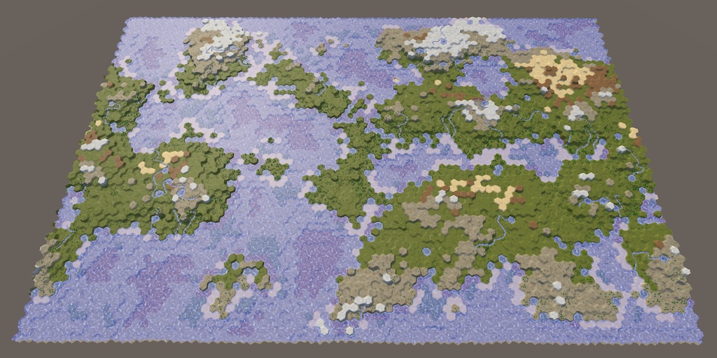
A collection of tutorials for people who want to learn C# and shader programming in Unity. Useful to both novice and experienced developers.
Theres a number of good tutorials there, if you're really looking to deep dive into shaders. Tbh I still have a hard time understanding them sometimes
!rank student
@clever loom, you left Student.
@clever loom #502893580512395264
I found a paper on some shading algorithms that I think are written/created for RSL. I haven’t taken a good look at them yet but I’m going to try to rewrite them in HLSL
hey guys I need some input. Im using a compute shader and its sped up the shader im working on but as I add more features theres more conditions and math involved and its starting to lag.
I was wondering what if I do the math on cpu side using burst compiler then just feed the data to the compute shader to draw. would that possibly be faster
@mortal kiln the math calculations are not good with cpu even do if you try unity uses the same class of mathf
yeah but isnt that what the burst compiler would come in useful for using native lists etc ?
i guess it wouldnt benefit from it would have to just try and compare maybe
Sort of. But remember, you have ?how many? cores and threads on the CPU? Depends on CPU, but on a GPU you've got like 256+ cores running in parallel.
And don't forget that you have to "ship" all that data up from the CPU to the GPU every frame, whereas if you keep it on the GPU you don't have to move it around.
So it all depends on exactly what you're doing and how you design it. Sometimes you do some of each, where it makes sense.
@mortal kiln
its for a raymarcher but the shapes/fractals get altered at times, or we dont know exactly what will be in a scene because its procedural . the current problem im facing really is when I subtract shapes from a bigger procedural fractal I start to feel the lag.
How would I recreate this in shader graph? I don't think shader graph exposes clip space? https://twitter.com/Ed_dV/status/1047007283467694080?s=20
Here are the nodes in Amplify Shader Editor. Remove the multiply at the end if you don't want to zoom compensate for depth (so more like traditional screenspace).
Also let me know if this is horribly inefficient and there is a better way to hook this up!

Per usual bgolus to the rescue
https://forum.unity.com/threads/what-is-the-equivalent-of-unityobjecttoclippos-inside-shader-graph.809778/
Unity Forum
Hi, I'm pretty new with shaders and started to look more into them in Shader Graph, and trying to convert from a script shader is not resulting on the...
It'd be nice if the built-in transform node had a clip space option
is there a way to write custom values to the hardware depth buffer? i have a custom ray tracing implementation in a compute shader projected onto a quad via render texture in front of the camera, so the camera's depth buffer will just be a low, flat value the whole way across. currently thinking of just using another render texture and faking it, but being able to use the hardware depth buffer would likely be faster
What operation should I do with the screen position node to convert a position in clip space to screen position. Is it just a simple multiplication?
Trying to achieve ComputeScreenPos() in Shader Graph
@solar sinew ComputeScreenPos does this :
float4 ComputeScreenPos(float4 positionCS)
{
    float4 o = positionCS * 0.5f;
    o.xy = float2(o.x, o.y * _ProjectionParams.x) + o.w;
    o.zw = positionCS.zw;
    return o;
}
You could just call the function in a custom function node to handle it though
Though since you mentioned the screen position node, it's probably already doing this
Would I multiply my clip space input by Raw Screen Position? Also I tried a custom function node but had some errors, I'll try again.
Raw
Returns Screen Position. This mode does not divide Screen Position by the clip space position W component. This is useful for projection.
Edit: Custom Function Node gives a syntax error: unexpected token: '('. I haven't used the string setting for the custom function node often
not using rasterization in any form, so there's no vertex stage
from the looks of it SV_Depth is used to access the depth value in a fragment shader; no good to me unfortunately because it'll just be a flat value!
(Bit tired so I'm a little confused sorry). If you already have a clip space position you don't need to use the screen position node, you'd just need to pass it into the ComputeScreenPos function or replicate what it does with nodes.
Looking at the amplify graph, the top part from Vertex Position to the Divide by W is what the Screen Position node (Default mode) already gives you, so it should be fine with just that. You would still need to handle the ComputeScreenPos for the (0,0,0) one though.
I've tried this clip/screen-space locked to object thing at some point before (for a dissolve shader specifically, so I didn't have to deal with uv seams). I think I had it working but also did it in view space which ended up as a much simpler graph, so that's what I included in the breakdown in the end. (Though it may have given slightly different results, that I can't quite remember). This might be useful though?
Would the (0, 0, 0) one be Screen Position node set to Center?
It's also not clear to me what the float Tex Scale is doing (in the amplify graph)? Your simpler graph works well but I'd like to compare it with the amplify graph's results
No, the Screen Position node will always give you the current fragment pos. You'd have to transform the object space (0,0,0) to screen manually : via matrix multiplication with the model, view and projection matricies to get clip space, then ComputeScreenPos.
You can kinda skip the model one if you use the Position output from tge Object node
ah okay. Sorry but I'm getting stuck on the string syntax in the CustomFunctionNode (of all the things)
Looking at the ComputeScreenPos in Functions.hlsl
{
  float4 o = pos * 0.5f;
  o.xy = float2(o.x, o.y * projectionSign) + o.w;
  o.zw = pos.zw;
  return o;
}```
which is basically the same?I think the TexScale is a property to control the textures tiling
Yea that function is the same, just with the projectionSign as a parameter instead of using _ProjectionParams.x
The function I posted with one input should be in the URP ShaderLibrary so you should just need something like Out = ComputeScreenPos(ClipPos); in the custom function
yeah I had tried that earlier and I get an error saying it fails to find the function
Hm okay, well could just copy the code in rather than calling the function
Tried that and I get errors for either not recognizing positionCS (URP ShaderLibrary code you posted) or undeclared identifier pos (second version of the function I posted from functions.hlsl)
same if it's written out as position
Well the positionCS / pos would be an input into the node
That's where you'd connect the (0,0,0) transformed into clip space
It's so simple yet frustrating when you just can't seem to get your syntax right 😓
Getting Incorrect number of arguments to numeric-type constructor error but this seems right to me? I must be missing something simple
Out.xy = float2(Out.x, Out.y * projectionSign) + Out.w;
Out.zw = pos.zw;
return Out;```(whenever I used o I was told it was undeclared)
I'd try float4 o = In * 0.5f; o.xy = float2(o.x, o.y * _ProjectionParams.x) + o.w; o.zw = In.zw; Out = o;
if I declare float4 at the start I get a redefinition error, if I remove it I get an undeclared error
hold on
okay finally
Thank you for bearing with me

No worries
Need to get some sleep though so hopefully no troubles with connecting it all up, good luck!
all good!
There is definitely some difference between the two graph's numerical output, but visually the only difference I find is scaling/tiling
Erm, currently on HDRP 2020.2.1f1
Why, all of a sudden is this happening? I duplicate some nodes and half of them turn invisible, not only that but suddenly i cant even drag new properties I create onto the blackboard....
Tried a restart, no change..
actually I CAN drag new properties into it, they just go invisible instantly -.-
does anybody, by any chance, have a halftone circle pattern texture? need it for my shader and cant find one anywhere
Hey all. Is it possible to do a colormask shader based on camera frustum? For example, everything inside white, everything outside black etc? Probably with like...transforming to camera space or something right? Not quite sure where to start though. Trying to paint pixels as red/green based on if they're visible to a camera (which I guess is like trying to make a custom shadowmap?)
Details with image can be found here : https://answers.unity.com/questions/1797832/best-way-to-paint-a-cameras-line-of-sight.html
Unity is the ultimate game development platform. Use Unity to build high-quality 3D and 2D games, deploy them across mobile, desktop, VR/AR, consoles or the Web, and connect with loyal and enthusiastic players and customers.
it seems I have hit some sort of render cap for my nodes, so now everything is invisible.
Therefore I have no choice, i shall turn into the Graph Whisperer and construct the rest of this effect using invisible nodes.
SO BE IT!
how can i make a delay in shader?
I think there's a time function / node
oh my god
why is there no syntax highlighting?? Is that how it's supposed to be?
I'm using visual studio with HLSL
there's literally nothing. it colors a few basic variable types blue, strings that weird brownish color, comments green, and numerical values a slight lime but that's it
it's really frustrating because I see, for example, youtubers' programs working fine with it. this is really frustrating. Am I missing some component???
download the extension - just like when you download other parts of VS, you need to download support for this language
how would i calculate the distance between the inner sphere and the outer cube inside the vertex function of the shader for each vertex?
And then set each vertex to a specific position from the inner sphere
Hey all! Brand new to shaders. Any suggestions on how to achieve a lighting style such as these "Atompunk" illustrations?
void disp (inout appdata v)
{
  v.vertex.xyz = mul((float3x3)unity_WorldToObject, normalize(v.vertex.xyz));
}
I'm trying to render a sphere at the world origin by interpreting the local space vertex coordinates as world space. This code doesn't work, it just renders the sphere at exactly the same position as before. Does anyone know how to fix this?
And btw, the sphere is miles away from the origin
I managed to solve it!
void disp (inout appdata v)
{
  v.vertex.xyz = mul(unity_WorldToObject, float4(normalize(v.vertex.xyz),1));
}
Any ideas folks ?
@bleak radish Using URP + shader graph, you could simulate the shape/size of the camera view with some vector math, then set color in the shader based on that, you would need every object to have some version of this shader for it to work.
can I ask what is probably a dumb question.. why?
since Unity culls most things outside of the camera frustum, you can see this in action if you use the occlusion feature and enable a setting to visualize it in editor.
someoe pls help me why this blurring??
Yes, but if he wants to do it, they can basically manually calc clip-space + perspective divide. So you'd need to pass in the camera location and camera matrix and do UnityObjectToClipPosition but with the non-scene matrix, and then do the perspective divide. Anything outside of the -1 to 1 range is "clipped". That's basically what the GPU does.
So I'd start with figuring out how to manually do clip space.
Regardless of what camera is rendering.
@odd willow Is that a tiled/repeating texture? Check your texture import settings for streatch vs repeating/tile/wrap whatever it's called.
ok i will
Has anyone tried another pass after tessellation pass? I am trying to overlay a wireframe pass inside surface shader. Here we can see it in scene view:
https://youtu.be/k2Z4IaY_Lfs
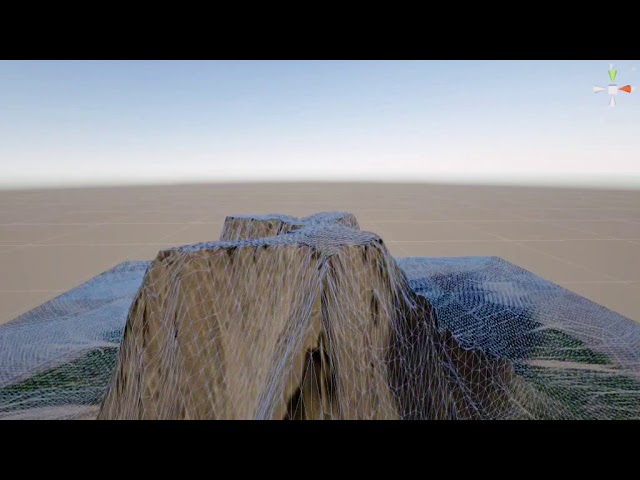
This video is a work in progress that demonstrates runtime vertex displacement and tessellation in a shader.
The tessellation is done based ok the distance of an object from the camera.
The displacement is done based on a map.
Why do it in a separate pass? combine it with the wireframe the first time.
https://github.com/Chaser324/unity-wireframe
May be of interest.
Also check unity's shader source for how they do wireframes.
GitHub
General purpose wireframe shaders for use in Unity. - Chaser324/unity-wireframe
And you can check catlikecoding for their discussion on wireframes.
And you can fake barycentrics using vertex colors if you don't share verts.
Wireframes are tricky, but there's several techniques. Not all of which are Surface shader friendly though.
Thanks for the reply. But they all use geometry shaders or function. But unity does not support the from function in surface shader
Try the fake-barycentrics.
For those also, how do we get the vertices added after tessellation? Would they be in the vertex shader ?
I guess Tess is before vertex right?
Yeah, it's it's own thing, more or less. It's more akin to geometry shader stuff, since it emits geometry, basically.
But I don't recall if Surface shaders support tessellation off the top of my head.
So you mean to fake bary coords via vshader and pass a value to fragment to shade ?
Yeah surface support Tess but not geom
Well, no, you fake it during modeling when you assign the vert colors.
So you assign (1,0,0) to one vert, (0,1,0) to the 2nd vert and (0,0,1) to the third vert. And you DON'T share verts among tris (and IDK if that's a tesselation killer or not).
Then as it interpolates, you can "see" how close you are to an edge.
Assign the vert colors in C#/modeling.
Hang on, I'll try and find something for you.
Ohh you mean to say outside the shader?
But then in that case, we won't have the data for Tess vertices as Tess is all based on distance from camera and alpha map
Probably, come to think of it.
Dang.
Sorry, brain fart.
Anyway, there's more info on the barycentric technique here: https://catlikecoding.com/unity/tutorials/advanced-rendering/flat-and-wireframe-shading/ He's using Geometry shader, but you can assign those values in vert colors too. He even mentions that, then you wouldn't need geometry shaders.
But with tesselation, IDK. You might be screwed,
But you could always take the output of the Surface shader (it's a code generator) and then ADD a geometry stage to it I guess if you want.

A Unity Advanced Rendering tutorial about flat and wireframe shading, using derivative instructions and a geometry shader.
No worries at all...
But again, I still don't know enough about how tesselation will impact that.
This is What I want to know, how to take the output of the surface shader and use that in a different pass?
Let me read through the article once
No,
We're talking about different things.
The surface shader generates actual vert/frag code. You can edit it after it is generated and paste it into a NEW shader. Then you're in vert/frag territory, but it generated all the lighting for you.
You can select the shader in the inpsector and ask to "view generated code". It's fugly, but it's there and you can edit it.
But the vertices are being added in shader at runtime
So even if I take the code, I won't be able to generate the wireframe at runtime 😬
The flow is like Tess - vert - geom - frag
And Tess is adding verts. Those will have to tap in vert shader
Let me try that
Yeah, that's why I said I wasn't sure about tesselation. Maybe someone else has a brianstorm.
but you'll have to go vert/frag and you can pre-generated lit code with the surface shader.
Lemme try what I mentioned earlier 😛
That might work 😃
But like you said, not in a surface shader......
I was just trying to get you to vert/frag
Yes. But not geometry.
I don't need geom then. I will use the vertex data and find triangles from that
hw you edit surface shader while there is no graph editor
If its possible then edge it out
But you can fake geometry with modeling and vert colors. BUT, then like you said, Tesselation will break that all up and IDK if it will mess up the vertcolors or not but you won't know the division lines.
There's a button in the inpsector, @hard mortar
But if you see the video, baking or faking the geom will add more load on rendering
Well, sure.
Did you see the dynamic runtime addition of mesh density in the video?
Yes, but it wasn't a surface shader.... 😉 Right?
It's a surface shader
There's only two! Try one. (It's the top)
If it weren't then I know the solution apparantly 😬
You cannot see the rendering quality because it's rendered in scene window 😛
Uh, your surface shader isn't doing the wireframe, per you.
Yeah exactly
The wireframe is beinf done by unity in scene
Yeah true that
I want that in game mode
Is there a way to tap into the wireframe shader by unity ?
That goes back to my first post!
See their code.
But you're not going to get it in a surface shader, I don't think.
You could render with a replacement shader?
If they can do it then we can also
The only question is how are they overlaying the wireframe
Replacement would not work it would replace the shader
If the shaders's an overly it might work (it only renders the wireframe pixels).
am i dump or what haha. when i click open it came up :
Idk if unity provides the source of its wireframe shader
Click on the "Show generated Code" button in the inpsector.
Oy.
Check first, because they supply a lot of their source.
That shader isn't there that's why I was wondering haha
Ah, well, that other link I gave you is "based on Unity's wireframe shaders".
It's probably stuff in the "utility" or whatever it's called section of their optional download of shader source.
You went out and got the shader source, right? It's on their downloads page.
Ohh let me check once 😬
Hehe yeah I tried downloading the source
I could have sworn I saw that shader a year ago or something, but maybe it was someone else's.
Anyway, yes, I think you're screwed with surface shaders, but maybe someone else can find a workaround.
If shader replacement doesn't work, IDK, and I can't tell you what shader to replace it with.
Why do you need a surface shader? Lighting, right?
No worries, you have been helpful 😃
Yeah lighting. I can write that code but eas trying to use what unity already has provided
Plus easier implementation of Tessellation
Sure, that's why I said just snip it out of the view-source. And then you can use the geometry-shader trick (post edit).
Yeah, that's waht m trying now hhehe
Then you can use barrycentrics.
Is there a way to make the default 2D shader be Sprite-Unlit-Default? Is this stored in the project settings somewhere?
Like this
I'm exuding optimism as I type!
lol
I might have to quit shooting my mouth off and go do it. But it's a lot of work to have to do that for everything you comment-on/discuss.
I suppose you could also just write your own SIMPLE vert/frag that overlays what's there (like a transparent pass) and clips all but the wireframe. So your own wireframe pass and render with that as a separate pass/replacement. The scene view must be doing something like that anyway, but danged if I can find it.
Anyone got a guide for making dynamic realtime emissive materials cast light/shadow?
(Not baked)
Did you try the emissive channel? That's what it does, it will "throw light" but IDK about shadows.
Standard pipeline's standard shader does it. You didn't say what pipeline.
Are there any courses for shaders only?
Hahah, yeah but then if we overlay where will we get the underlying vertexninfonwhich is generated at runtime 😛
Inhave been able to get a vert func in surf shader now will try that tomorrow 😅
That's what I've been doing so far, but it does not cast shadows or any real light in the world. So not sure what to do from here.
Emission won't cast shadows or act as real light
@topaz urchin what are you trying to achieve here ?
I can simulate the camera frustum's shape. But just don't know how to paint everything seen by the camera to green and everything not seen to red.
To show what's occluded and what's not?
In my game I'd like to give player the freedom of putting cameras to observe enemy movements (just like in R6S outdoor cameras) and want to show the player where that camera can see and can't. That's the base of the idea.
I just something like camera frustum shaped light source ?
i just need*
I can draw a frustum shaped mesh depending on the unity camera component
Instead of putting cameras, create your own object/light type with a frustum. That will be much better as you don't have to add cameras. Because cameras won't let you render what's clipped :)
How can I create frustum shaped light ?
I've tried projector's but there were no shadows...
You don't have to do that. Make a simple object with a mesh component.
And make the mesh like that frustum
So once you are able to modify the mesh at runtime, you will have your own frustum object. 😀
I've already done that. But the thing is I want to paint every face seen by that camera and not seen inside it's frustum
(Terrains and meshes included ) 😄
Then you can fetch all the vertices present inside that frustum to whatever you like
Unity is the ultimate game development platform. Use Unity to build high-quality 3D and 2D games, deploy them across mobile, desktop, VR/AR, consoles or the Web, and connect with loyal and enthusiastic players and customers.
It's simple wait let me draw it for you
oh lord. I'm waiting 😄
Now instead of making C1 as a camera. Make an object and create custom mesh on it. This mesh will have a mesh filter which will have vertices.
You will have to code that frustum behaviour of it. just like it's mentioned in the link you sent
Then you need to apply a shader which would do a stencil test so that whatever is present behind it is colored with whatever the color you provide to the shader 👍
I see
I've already coded the frustum behaviour. Just need the shader but not sure if stencil works for that.
And I'm not really good at shaders
ok waiting
https://youtu.be/594NXLc9gmA
Take a close look at this shader. Whatever is behind the lens has a stencil test done for it. Hence, creating night vision effect. If the solider is out of the lens, it is rendered the way it was

Here's an implementation of a shader in unity which enables to crete a night vision effect with a thermoscope to easily get behind enemy lines. Looking forward to comments/feedback!
Also you have to use the concept of replacement shaders 😀👍
Would those ideas work on terrain too ?
I mean stencil shader and replacement shaders or so ?
As far as I know the graphics pipeline, it depends on terrain shader
What material and shader do you have on terrain?
standard unity terrain shaders
Okay haven't gotten much idea.
But remember one thing. replacement shader and stencil test won't help you get occlusion culling effect where you see the red and green areas in the image you shared
As you mentioned earlier you just wanted a simple color in clipped vs non clipped area
Anyway , thank you so much for sharing ideas !
Appreciated..
I'll try to seek for more ideas
maybe two pass decal works ? I don't know 😄
Hehe, not decals. It's like if you want to do per obtejxt occlusion then you have to write your own occlusion system or get the data from unitys occlusion system
Like @thick fulcrum said, use the vector math. I made a post above. @bleak radish
The GPU knows how to do this for the view camera, but it's more about you having to do clip-space manually in this case, for each camera that is NOT rendering right now. So you'll need to either have a camera and a proper set of matrix values for it, or calc a frustum somehow. It's clip space, it ranges from -1 to 1 and there's a perspective divide (distance based divide in .w component of the position). That's how GPU's already doing culling per pixel. You just have to do that perspective divide and calcs manually.
BUT....you'll be limited as to how many cameras you can have doing this, since you can't pass an infinite number of things through the interpolators. And you'll have to manually check and color each pixel in the frag(). Or you'll need a compute buffer(s) with the various camera info array and run through the calcs for each pixel (argh!). Better to do it on a vertex basis.
Anyway, that's how you tell if a pixel is inside or outside that frustum shape. If it's outside of -1 to 1, or it's depth is out of range, it's not a visible pixel. That's assuming you want to cover the frustum volume (volumetric calcs). You COULD just create frustums for each camera as game object meshes, and color them with a transparent effect, but it won't look the same as what you described. And it won't work if you walk inside of one.
how can i fix this error? if i do have to get some renderpipeline, which one would be compatible?
this is just from the unity shader graph stuff
Shader graph doesn't work in the default render pipeline, which is what you get when you select the template with just "3D" @smoky pewter
If you want to make use of shader graph you'll have to change or upgrade to URP or HDRP
do i just download urp/hrp from the package manager?
You can upgrade through there yeah
if i install one them will it start working or will i have to go through more setup
since i got urp but its still showing the error
I've not done much upgrading myself, I usually select the templates
Maybe ask in #archived-hdrp?
No prob! If you made sure either scriptable render pipeline is correctly installed it might be an issue with shader graph