#archived-shaders
1 messages · Page 154 of 1
thanks!
just grab the part about scriptable render feature, add that to your project then you can get the texture in shadegraph and work with it.
Anyone know a way I can have a transparent material in shader graph that doesn't have these weird depth issues? This texture doesn't even have any transparency, but it's showing the far side of the cylinder in front, and the meshes off in the distance in front of it.
I've got the alpha channel of the texture mapping to the alpha of a PBR master node, and I've changed it to transparent in the shader graph
@echo badger This project is take a bit dust, but I have an example of doing a planar cut with shadergraph : https://github.com/Remy-Maetz/ShaderGraph_Doodles

GitHub
Contribute to Remy-Maetz/ShaderGraph_Doodles development by creating an account on GitHub.
@thick fulcrum Great, thanks I will see how I exploit this
@atomic glade That how transparency work realtime.
If you object is composed of transparent and opaque parts, it's better to split them in multiple materials.
@echo badger That's how it looks : https://gyazo.com/1beb7c1eb2b0dba6f725207d40c4054f
How would I go about splitting them in a way that would work from any angle?
They're already split, but they're all using the same shader
Transparent shader for transparent part, opaque shader for opaque part
So there's no way to have something opaque that can become transparent by adjusting the alpha?
Pretty cool, thanks @amber saffron! Do you happen to know how performant heavy it is/isn't?
Didn't really try to benchmark it. Should be pretty light though, as it's only doing an alpha clip
I'd like to be able to fade a polygon so I can see what's behind it programatically, and my plan was to just adjust the alpha multiplier on an opaque texture so an individual submesh can be transparent. I've got them split into different materials already
Oh, that's cool. I would imagine it would pretty light then. I will take a look at it, thanks again for sharing!
But even when fully opaque the depth doesn't work right
Alpha = 1 doesn't mean "opaque", that depends on the shader setup of transparent vs opaque
Is there anything I can do to achieve this effect then?
Assign an opaque material on all the polys you want to be opaque, and a transparent one to the ones you want to be transparent, using submeshes
So, just make two copies of the shader, and switch shaders whenever I want to fade one?
yep
@atomic glade What you MIGHT try, is to render this thing in it's own queue, if you want geometry+1 or even the transparent queue. Do depth testing, alpha blending, cull backfaces, and fade the alpha. Unity has shaders that do fade, IIRC.
Another option, if you don't mind the effect, it to fake-fade using screen-space dithering in the opaque queue.
Is there a way to generate dithering in Shader Graph?
Sure, as long as you can do a discard, but it might require a custom node. You'd feed in the alpha value, and it would look up the screen-space modulus (say 64x64) and compare the alpha value and discard or not. Google "screen-space dither".
Shadergraph has a Dither node, https://docs.unity3d.com/Packages/com.unity.shadergraph@8.1/manual/Dither-Node.html
Even better!
Then you'd compare the output of that to the current pixel's alpha value.
Okay, I'll try a dithering approach to fading. Might even make for a cooler effect than just straight transparency
All depends on what you want. But you can handle it in the opaque queue
Another question, the PBR materials I've downloaded all have a displacement map. Where does that go in a PBR master node?
@mortal sage also check out this
GitHub
World space normals texture for Unity's Universal Render Pipeline. - Kink3d/kNormals
it's another implementation, but should be similar to mine
would love to see what effects you use it for 🙂 feel free to tag me
I used the texture to make a very primitive ambient occlusion effect
Heyo, I'm quite new to shaders and I would need some help. I followed this tutorial to give my UI text a pixel perfect outline:
https://www.febucci.com/2019/06/sprite-outline-shader/
However, when I try to thicken that outline, instead of it getting thicker it just appears at the opposite side of the element.
I changed this:
fixed bottomPixel = tex2D(_MainTex, i.uv + float2(0, -_MainTex_TexelSize.y)).a;
To this:
fixed bottomPixel = tex2D(_MainTex, i.uv + float2(0, -_MainTex_TexelSize.y * 2)).a;
Any help is appreciated! :)
Febucci
Discover how to create an outline or inline shader for your sprites in this simple tutorial, using both Unity Shader Graph or HLSL. Read more!
I've downloaded a few PBR materials, and they all have a displacement map. Where does that go in a PBR master node in Shader Graph?
nowhere usually
if you really need some depth illusion, you could use POM node with it, but do note it's more expensive
also you could diplace the mesh with the data but it's kinda pointless as there's no tessellation support on shader graphs, so if you just slap it into dense mesh, you could have just baked the height to the mesh itself
Is it possible to get stencil buffer working in a PPv2 custom shader with forward legacy rendering pipeline? How?
hey I think I remember something being mentioned here about Material property blocks with shader graph shaders not gpu instancing properly, or am I misremembering?
How would I go about making an outline shader in URP? I've found some tutorials for writing one for the old render system, but I don't know how I'd make one in URP, with or without Shader Graph
@atomic glade In URP, I would recommand to go with shadergraph.
If you need a 3D outline, use the "shell" technique, bu re-rendering the mesh with inverted faces and pushed
For a 2D sprite outline, the best is to precompute a outline in the sprite as a "gradient contour" like a SDF, or you can do multiple samples by pixels and offseting the uvs to check for outline
What is the shell technique?
for a sprite, you can do in shadergraph what is done in amplify here : https://www.febucci.com/2019/06/sprite-outline-shader/
Febucci
Discover how to create an outline or inline shader for your sprites in this simple tutorial, using both Unity Shader Graph or HLSL. Read more!
And for 3D, you can look at the examples here, outlines as hull, or as postprocess : https://github.com/Unity-Technologies/UniversalRenderingExamples#toon-outline

GitHub
This project contains a collection of Custom Renderer examples. This will be updated as we refine the feature and add more options. - Unity-Technologies/UniversalRenderingExamples
@atomic glade Did you have any luck with the dither-fade?
I actually wound up just toggling between the opaque and transparent shaders
I had to make transparent versions anyway for some materials that were transparent all the time, so it just seemed easier to do that
I'll check out those examples, I found a Youtube video of Unity using those toon shaders, but they're not compatible with URP and don't work in 2019.3, maybe the examples on the site are updated?
dose anyone have experience with perlin noise?
@echo badger That's how it looks : https://gyazo.com/1beb7c1eb2b0dba6f725207d40c4054f
@amber saffron wow thats nice
@tepid vector what kind of black magic is that !?
@echo badger This project is take a bit dust, but I have an example of doing a planar cut with shadergraph : https://github.com/Remy-Maetz/ShaderGraph_Doodles
Its a public repository from @amber saffron
GitHub
Contribute to Remy-Maetz/ShaderGraph_Doodles development by creating an account on GitHub.
You can see
Not sure where to ask this. I started my first 3D project and I am confused on how to get a texture to tile depending on the size of an object.
... You don't need to do an exact quote 😉
hello everyone. I have a problem with Instancing using DrawmeshInstanced and WebGL build. on editor/windows build and firefox everything is ok. on Chrome since an update a couple of weeks ago the instanced colors are meshed up.
nothing changed on my code though. I have older webgl builds that have the same problem.
is there any way to mix to different materials based on percentage or values?
@raven timber can you elaborate or have example picture, as to me mixing materials is wood and glass on same object which can be done with standard shader.
here 1 have 2 materials and 2 different shaders
on collision.. i want blue as base.. and red material will be as blinkin on blue
get me ?
ok that's more swapping materials, not mixing per say. Depending on the shaders you might get away with both on same model and just swap their order in code. Alternatively you swap the material via code at runtime.
Or they don't look overly complicated materials, you could roll them into one material / shader and just adjust colour and other variables from code when collisions detected.
ok thanks..let me try combininb them in one material : )
i have a problem... im not sure how to solve
i need to dispatch a compute shader when another one is done
that's fairly easy, as you pull back the data to cpu can send that data to another compute shader at that point or just trigger next compute. But pulling the data from gpu to cpu will be a bottleneck, ideally you want to pass the information on IF it is reliant on previous. but that's beyond what I've experimented with.
I'm assuming fholm is passing his compute shader output to a normal shader
Rather than getting it back to the CPU
I'd just create another kernel that calls the extra compute shaders code
He needs to know that all processing for <A> is done, before he calls the kernel for <B>. IDK if that's automatic in Unity from separate kernel invocations (like some internal barrier) or if you need to make use of (code) some kind of barrier. Lemme dig around. I know I read something on this.

@orchid briar
Of note GPUFences do not need to be used to synchronise a GPU task writing to a resource that will be read as an input by another. These resource dependencies are automatically handled by Unity. That's a tad vague to me, but it's promising. IDK what happens if they're both R/W...or how unity even detects this...probably automatic too.
Problem in Shader Graph with UV Node
I get an error and I do not know why
What I want to access are the UV coordinates of the mesh
I use the universal rendering pipeline
I don't think you want UV coordinates passed into a spheremask node. Maybe some kind of worldspace thing?
hello everyone. I have a problem with Instancing using DrawmeshInstanced and WebGL build. on editor/windows build and firefox everything is ok. on Chrome since an update a couple of weeks ago the instanced colors are meshed up.
nothing changed on my code though. I have older webgl builds that have the same problem.
hello all, i am stumped with something and need some guidance. I am trying to create a debug view where the screen is split into thirds. But I'd like to split it in radial segments so that I can better visualize a problem
like so
does anyone know how I can split uv into a radial like that?
Relative to/split-by what?
jus screen size, black being the screen space uv
red being the third split
white being the outline generated by snipping tool
But...you're putting different things in different areas, right?
IDK, you could use a mask I suppose, and mask it off in any shape you want. That's probably easiest.
So color it in a custom full-screen shader to display X if the mask is 1, Y if it is 2, and Z if it is 3 (XYZ being the three results). Then just draw your mask in whatever shape you want and pass it in.
Make it look like a checkerboard if you want, or big-bird.
Thats what I'm aiming for. Masks are a way, but would like to do this programmatically so I can add debug views as I go along.
and just add more pie slices
You can either build the "debug view" into your individual shaders (you said compute shader) or you can build it into a separate post-processing pass if you have the data. That's still "programatic". But otherwise you'll have to figure out the math of the center point of the screen and the triangles instead of the mask.
IDK what to tell you.
debug views are there, just need some guidance on radially splitting a square
thank you!
will dive deeper into the interwebs
Well, if you just want "pie slices" then compute radians and divide it up into slices. Doesn't really matter if it's a square or not around the edges. Just compute the angle.
thanks again. I managed to sort it out, wanted to post here, but not allowing me to paste code
@meager pelican I want to use the uv coordinates as I use the sphere mask to make perfect circles for selection indicators that are simple quads with 0,0 to 1,1 coordinates
This way I can reuse the shader material for every selection quad with the same color
I'm trying to use some effects from Unity's Universal Rendering Examples: https://github.com/Unity-Technologies/UniversalRenderingExamples/wiki/Toon-Outline
And I'm getting this error whenever I try to bring over some of their renderObjects:
Assets\RenderObjects.cs(63,59): error CS1503: Argument 6: cannot convert from 'UnityEngine.Experimental.Rendering.Universal.RenderObjects.CustomCameraSettings [Assets\RenderObjects.cs(46)]' to 'UnityEngine.Experimental.Rendering.Universal.RenderObjects.CustomCameraSettings [Library\ScriptAssemblies\Unity.RenderPipelines.Universal.Runtime.dll]'
GitHub
This project contains a collection of Custom Renderer examples. This will be updated as we refine the feature and add more options. - Unity-Technologies/UniversalRenderingExamples
I'm not really sure what this error is trying to tell me? It looks like it's trying to convert something to itself...
@meager pelican I found the problem. My Reference name for the parameter was off
Okay, I think I found it. I was copying over some code that already existed in the generic URP and I didn't need to copy over. Disregard my question.
So is it better or worse to use same material for multiple meshes and adding a per instance variable to modify the differences? I don't think I can benefit from batching since these will be doing effects based off object space stuff. I'd assume if the per instance data never changes the only difference would be saving some minimal memory on GPU?
The materials will use per instance anyway.
Hi all, is there a way to adjust the 'default-material' so it is GPU instanced by default?
I made SUPER COOL FIREWORKS using Unity....check it out.I hope you wanna tag along.so if you are interested , subscribe....
It's in the #✨┃vfx-and-particles
Check it out
Hello there,
Is there a way to make a stencil shader in HDRP
I've been looking around the web for an hour and i've found nothing
Hey guys, noob with shaders here... I got an URP unlit shader that cast shadows, but this shader didn't come with the color property. I'm trying to place this property but I have no idea where to place it... Someone can help-me? https://pastebin.com/fPZntS0X

https://gyazo.com/5a95e8a33fa7472cca47e459415760b3 Everytime when I ugrade my project to HDRP. Why this is happening?

I am getting an error in one of URP shader:
Output variable LitPassVertex contains a system-interpreted value (SV_RenderTargetArrayIndex) which must be written in every execution path of the shader. Unconditional initialization may help. at line 283.
Any clue, I am quite unaware of shaders.
@vivid kernel Don't use shader global keywords, use locals.
Unity is the ultimate game development platform. Use Unity to build high-quality 3D and 2D games, deploy them across mobile, desktop, VR/AR, consoles or the Web, and connect with loyal and enthusiastic players and customers.
I'm trying to make a glow material and I'm not sure why this shader won't render in the preview or the scene. I'm really new to shader graph and unity in general is there something I'm missing here?
@unborn perch Your colour node has an alpha value of 0 (shown by the black bar below it), so it's fully transparent.
@regal stag Oh thanks I never even knew that existed
Would anyone know if this is a shader issue?
Check the purple assets on the right side
@coral otter yes
but it's tricky
there are basically two stencil bits left for users on HDRP (at least on the recent versions)
but you need to write those stencil passes manually, you can't use shader graph
@fervent tinsel can i do it the old way ? Like writting ```cs
SubShader{
Tags { "RenderType" = "Opaque" "Queue" = "Geometry+1"}
Pass {
Stencil {
Ref 2
Comp Notequal
Pass keep
ZFail decrWrap
}
CGPROGRAM
For the stencil part i mean ?
Or is there another way ?
you have to use the stencil pass in current HDRP structure
like, you see that in HDRP shaders and SGs generated for HDRP
but yeah, it's very similar to what you pasted
May you have an example ?
Because i have no clue about how to do it from anywhere on the internet
look for HDRP postprocessing shaders
pretty sure SMAA does this
altho that might be on compute
But this mean i must apply it on a post processing shader ? I cannot put it on a material ?
not sure if I understand what you ask now
I'd assume you can put it on any shader
I haven't done it though
all I've done with this is overwriting stencil data using custom pass: https://discordapp.com/channels/489222168727519232/517108768933281843/669395847787708426
that sample overwrites all bits tho
Well, thanks @fervent tinsel i guess i'll dig into how to reproduce by die and retry. I'm not a shader guy so well, i'm not sure to understand any of what i'm doing :D
If i ever manage to achieve it, i'll post a package here with the effect
you can see the stencil bits here btw:
https://github.com/Unity-Technologies/Graphics/blob/master/com.unity.render-pipelines.high-definition/Runtime/RenderPipeline/HDStencilUsage.cs.hlsl
https://github.com/Unity-Technologies/Graphics/blob/master/com.unity.render-pipelines.high-definition/Runtime/RenderPipeline/HDStencilUsage.cs
just be aware this is the current setup they have on HDRP, I don't remember if that was already like that on 7.x but I think they use that on latest 7.3 at least
they've changed the stencil system 2 or 3 times already on HDRP
I've no idea what is a stencil bits, i just puted the line Stencil and Ref in my shaders and it worked like magic 
So i guess i'll just look in the hdrp shaders and find a way to place the same words at differents places and see
they use bitmasks so that they can pack 8 different things on single 8-bit stencil buffer
userbits are the last two (64 and 128)
That's super kind from you, but it's no use to try to explain me this, i just don't have the right education to understand 
I'll just dig and try stuffs, thanks again for your help
np. good luck
Well in fact
It look like it's just build in when you choose an object on the default HDRP shader as transparent
how do you get the sort of lightsaber glow effect using shadergraph
i tried to use the fresnel effect, but to no avail
Look up a post-processing effect called "bloom" to see how that "glow" is often done. Also "emissive" colors from your shader if you want it to cast light. Fresnel might give you an interesting base color though.
glow is the hard part for me
it seems like the flow is restricted to the shape of the object, it's not actually emitting any light out of the object
i tried turning HDR on, but that didn't help either
Hello, I have been researching this answer for about a week now, but I still have no clue. I've been trying to recreate this Force Field effect in Blender https://youtu.be/NiOGWZXBg4Y , However, I have no idea what the Scene Depth node set to "Eye Space" output is doing

Let's learn how to make an awesome force field with Unity Shader Graph!
● Check out Skillshare! http://skl.sh/brackeys15
● Support us on Patreon: https://www.patreon.com/brackeys
● Project Files: https://github.com/Brackeys/Force-Field
● Water Shader shown in intro: https:...
The main problem I have in trying to do this effect in Blender is not knowing what the "Eye Space" option of the Scene Depth node is doing.
Depth pass shader for cracks?

GitHub
Purpose of this PR
Problem
Currently, the master node definition is too rigid and defined via leaky abstractions. This gives the the following problems:
Large list of individual master nodes. Chan...
quick question: I'm trying to "chunk" 2d lighting into 10x10 pixel squares - think terraria lighting, but I'm not using a tile system - but I've never actually worked with shaders. would that be an appropriate use for them?
to be more specific I don't want those squares to overlap
its not strictly a shader question but is there a way to force unity to open shaders in a different ide than whatever the main one is? like for shaders open vscode, c# open rider?
Hello, I would like to use Parallax Oclusion Mapping with Triplanar, but in the shader graph, the output of the Triplanar is an RGBA (or I would like to have UV to plug it in POM). Any idea ? 🙂
@dapper pollen How about you have your asset folder open in an explorer and set the default IDE for .shader files as your desired IDE. Dont think that you can set multiple IDE's inside Unity though.
@rich flume As I understand it, POM is a simplified ray-tracing technique to alter the surface depth. As such, you'll have a heck of a time in SG IMO due to the loops. You could maybe use a custom node and code the thing yourself.
Or edit the generated code
@versed gorge "Depth converted to eye space units"-https://docs.unity3d.com/Packages/com.unity.shadergraph@6.9/manual/Scene-Depth-Node.html
Basically, it is the actual distance in units from the camera position independent from the near and far clipping plane of the camera. It will be very white very quickly, because everything further than 1m will be maximum white already. (Though the values won't clamp at 1 and exceed further)
I am getting a heavy amount of swappy errors (Failed to wait for fence) when I have a lava shader running. Anyone familiar with this type of error?
Does anyone know what shader Unity uses to display a navigation mesh in the Editor?
I downloaded the builtin_shaders but I just cant find it
Hi, i dont know if this is the correct channel to post this. I'm trying to do some simple verlet cloth with a compute shader, but strangely getting eratic behavior on my constraint kernel, It seems like the constraints are computed but there is a ton of jiggle, and the entire unpinned particles are falling to the abyss, the same algorithm runs fine in cpu version. i dont know if there are conccurent access that affect the particles positions simultaneously and creating these artefacts or if i have set up the number of threads groups the wrong way. Can someone with compute shader experience enlighten my lantern a little bit on that matter. i will share the code in pm.
Hey, does anyone have any kind of metrics for compute shaders in Android? I know it runs on most of android devices, but I hear its incredibly slow?
Does the speed change at all if you use bin-sized dispatches? Unfortutanely, I dont have the devices on hand to test myself, so any information would be appreciated, thanks.
Did unity remove the scriptable render pipeline repository from github?
GitHub
Unity Graphics - Including Scriptable Render Pipeline - Unity-Technologies/Graphics
Ah, thanks! Was panicking there for a moment 😂
Hi, im want to paint triangles, which works, but i also want that the triangles are drawn with hard edges. Im using a fairly simple shader ``` struct Input {
float4 color : COLOR;
};
    void surf (Input IN, inout SurfaceOutputStandard o) {
        o.Albedo = IN.color;
    }``` What i have to do that the triangles with color drawn with hard edges ? (thats how it looks atm)
can someone explain why the following doesnt work? the bit of it is plugged into albedo
there is no change at all with color no matter what "depththingie" is set to or how far away the plane is from other objects.
not even just sticking this section into albedo works
@sonic bear Is the master node set to Transparent surface type?
let me check, also funnily enough i was trying out your solution for a similar shader on your website ealier @regal stag
If you are using URP you'll also want to make sure the Depth Texture option is enabled on the URP asset
I am using lwrp
LWRP too, same thing
and itis set to opaque, also how do i do that
?*
wait found it
let me try it out
so i turned depth texture on however the issue still persists @regal stag
For the Scene Depth node to be useful, the surface type needs to be Transparent (or the shader needs to be moved into the transparent queue via the Render Queue in the material inspector). If it's opaque it will return the depth of the object itself (which is equal to the Raw Screen Position -> A, so when subtracting them the result is 0).
thanks it is working now, that was the issue
For the Scene Depth node to be useful, the surface type needs to be Transparent (or the shader needs to be moved into the transparent queue via the Render Queue in the material inspector). If it's opaque it will return the depth of the object itself (which is equal to the Raw Screen Position -> A, so when subtracting them the result is 0).
@regal stag you are saying sceneDepth.eye-screenPos.a=0
@ionic brook For an opaque shader which writes it's own depth to the depth texture, yes.
does anyone know how to make a splatmap in shader graph?
@waxen hollow you'll have to use a mesh where all triangles are separated (don't share vertices)
@sonic bear You don't make a splatmap in shadergraph, you use it.
wait they have one already in there?
Alright, thx^^
A splatmap is usually just a texture that comes from another source, like the terrain system.
A splatmap is just a texture
well i mean that is fair enough, but i have no idea of how to make one
i know how i would use it;
replace [color] with texture
but i dont know how to make it so that the texture is made in the first place
What is the final thing that you are trying to achieve ?
something like this so i can just go into shader graph and replace the color with the appropriate texture
So, you already have the splatmap here
no that is from google images
Oh, ok
In unity, when you paint a terrain, you're editing a splat map
One common way to work with splat map is that the sum of all the channels (R+G+B+A) = 1
So that in the shader, you can multiply the different texture samples of each layer with the corresponding channel value, and add them together to have the final color
maybe i am in the wrong channel, but i dont need help with converting the splatmap texture into the final material. i need help making the splatmap in the first place
Any texture painting or image editing software should be able to help you here
It's just an RGBA map
no like in unity during runtime
How do I make objects get borders when the mouse is over the object
the mesh in question is a flat plane, so the texture is just a square texture with no weird uv stuff to worry about
@open grail have you checked the asset store?
So an easy solution would be to use a separated camera that renders in a RT, and use this RT as splat map
You can then paint on it by placing the RT as background of the camera, and draw objets (your brushes) on it
you know what that makes sense, can render textures just be thrown into a texture slot of shader graph or do have to set something up?
@open grail hope it works!
You can assign them just like regular textures
Thanks!
okaaay, thanks for the help, i will try to mess with that right now
If you want to avoid the camera route, you could try custom render textures, but you will have to write a dedicated shader to "paint" on it, and shadergraph will not help you there.
I can't figure it out
I don't know
Maybe I can make it so the gameobject lights up instead when mouse is over it
And then go back to its normal brightness when the mouse is no longer over it
oops wrong channel sorry and thank you
Is it possible to create custom volumetric fog in order to add wind effect and to adjust his height in function of terrain height ? (with shadergraph)
Hiya, I was wondering, is there an option to view dynamicslices files easily? I just want to view the object in an easy way
Does any one knows how to override the wind effect of the terrain grass shader ?
"Hidden/TerrainEngine/Details/WavingDoublePass"
why does setting the o.Normal in a shader throw a Shader error in 'Custom/triplanarGround': Surface shader Input structure needs INTERNAL_DATA for this WorldNormalVector or WorldReflectionVector usage at line 187
i'm doing a standare custom shader
I remember that putting that was causing me error elsewhere
I don't know I'm not familiar with shader
Hey, I'm trying to write a shader that adds an outline to a quad
is there any way to do this in one pass?
actually, it's not always a quad but is always a flat mesh w/ usually 2 tris
well, I have a post-process shader that works...but seems like there isn't any way to do it in a regular shader, regardless of the number of passes
in a vertex shader you can do it
you duplicate you vertex with a greater offset and inverse the normal of the new created vertex
be awar it will duplicate the number of tris by two of the mesh you trying to out line
how would I know what the 'offset' is for the new vertices?
my UV/texcoords are shifted, and there is only one normal since this is a plane w/ orthographic camera
I guess I could do something like set the 'center' of the mesh in a shader property externally and use that to extrude
it's likely to make a mess though
I agree that's a poor answer for a quad, but technically you can do it single pass w/ similar theory. If you know enough about the size of the outline and the shape you want to outline for, you can expand the vertices in the vertex shader and mark out the line area with an SDF
you're at minimum going to need to change the clip (fancy way of saying 'screen') positions of your vertices, though
whether you do that on the CPU or on the fly is up to you
would check out some of the wireframe shaders for explanation of the edge detection bit-- quads are probably easier than triangles since you can usually just work with texture UVs instead of barycentric coordinates assuming you use the whole 0-1 range on the quad
Anyone ever had this problem? My shader renders gray :/ I use unity URP is it a problem?
Here is what my shadergraph looks like
might also need to be a translucent shader too
the scene color node only works if you enable OpaqueTexture
master node
Im starting with shaders x3 What does it mean?
I know the 3D masters have the same limit (and it's hinted at in the tooltip in the image)
What's the solution? :c
I've looked through multiple unitys forum and it seems like using shaders and URP is clearly impossible.
If anyone knows a solution or something, thanks
"Set the Surface Type dropdown on the Material Options panel of the Master Node to Transparent to receive the correct values from this node." @grand jolt
Does anybody know how an effect is called where 2 intersecting 3d models somehow get their vertices smoothed and textures blended and so it looks like they're a single mesh?
@gleaming moss unfortunately none of that works for me since my planes could be w/ arbitrary shapes and UVs
I think I'll stick w/ my postprocess effect for now
Hello, i'm new using shader graph, and i can't enable post processing on URP
i've tried so many things
do you mean custom postprocess effects, or the regular stuff?
there are like 20 weird and useless things you gotta do
sec
Unity is the ultimate game development platform. Use Unity to build high-quality 3D and 2D games, deploy them across mobile, desktop, VR/AR, consoles or the Web, and connect with loyal and enthusiastic players and customers.
ok, 8 - scroll to the first answer
i'm not using post process v2
i'm trying to use the integrated universal render pipeline post processing
i've tick the Render Post-processing, tried to check all the layers, my volume is fine and my pipeline asset is fine
here is my volume
Can someone tell me why this shader is only displaying as black/transparent?
https://hatebin.com/ugqbfgwfmd
hmm is volume trigger being set to none supposed to work?
i've tried settings to every object on the scene, even the camera
none of them work
the shader itself is fine
but i really cant get the integrated post processing to work
I would try with a known working project and compare
this project is new
i've just followed those steps

Create your own 2D Shaders with Shader Graph!
► Check out Zenva's RPG Academy: https://academy.zenva.com/product/rpg-academy/?zva_src=partner-brackeys-rpg-2020-02
● Project Files: https://github.com/Brackeys/2D-Shader-Graph
Free assets used:
● Pixel Adventure 1:
https://ass...
but for some reason urp post processing doesnt work at all
what is your player quality set to?
Guys I'm a complete noob about shaders, do you know if it's possible to create a shader that fakes depth without using another camera ? Like those examples of making portals that track player position and rotation to fake perspective; I'd like to make fake windows with this, but just using two or three layers of textures, would be some sort of parallax but tracking player position/rotation, not sure if I explain myself
this thread seems relevant, but you probably tried it all @wooden kite https://forum.unity.com/threads/urp-post-fx-visible-in-editor-not-in-game.779570/
Unity Forum
Hi
I am having trouble getting the postFX to work.
I have created a game using the URP template. Following the documentation I added a volume to my...
it is not visible, even on editor scene
have you checked the buttons along the top of the scene window?
I think one of them is for post
looks off in the screenshot
this one ?
yeah, and the one to the left
if you add the volume to the camera GO instead, is it still broken?
yes
x.x thanks
what's in your pipeline asset's postprocessing dropdown?
well, let me check if anyone has reported a similar issue
no luck
@wooden kite is your volume and camera on the same layer?
and also I looked in the wrong place...actually a lot of bug reports, but mostly VR/XR
@wooden kite is your volume and camera on the same layer?
@lavish sierra yes
how does one make a glowing object, like a lightsaber using shader graph?
i tried using the fresnel effect, but I want the center to not react to lighting
are you using HDR rendering
the 'white core with colored outline' thing is purely an exposure + bloom thing that cameras do. If you have an HDR system, just make a flat emissive object with a super bright value and the glare system will do the rest
also works correctly with partial obstruction and all that good stuff
@shy spruce I already answered that for you. Use bloom. That's "glow". You can also use emission to emit light into lighting. Bloom is in the post processing stack. And you can try HDR too if you wish.
P.S. I see I.P. answered too.
how does one add boom?
i installed the post processing package, do you add bloom to the object or to the camera?
Since it's post-processing, it's added for the scene (well volume) as a whole, not the object. Sec.
https://docs.unity3d.com/Packages/com.unity.render-pipelines.universal@7.1/manual/integration-with-post-processing.html
https://docs.unity3d.com/Packages/com.unity.render-pipelines.universal@7.1/manual/post-processing-bloom.html
You shouldn't have to install another package, as I understand it.
looking for someone who is great with textures and material in unity , i need an important information before i even start to model
im looking to create a model for our aquafairy but want parts for them to have a random color generated on load, and i need to know how to make multiple part of a model support multiple color changes
they all have random colors for
-cap
-squishies
-skin
-eyes
-mouth
using diferent material on edge of geometries is out of the question
since the shapes of the marks / spots on them would overlap with the body geometry and fuck the whole thing up
is theres a thing on unity to handle multiple layers for material or how i would have to implement this thing
It seems like you've posted a bunch of information for your question, quakeman, but I honestly still have no clue what you're asking
Probably the right thing to do would be to bake textures and then still have just one material with exposed properties for your colors, using a shader to map a grayscale set of colors from the texture to whatever it is you need
But I'm no expert
color ramp work well for toonish style / pixel art
but for complex texture thats alot of colors to account for
if youre talking in the palette swap method
basically i was asking if theres way to make layers to change part of a model , like skin is 1 layer , spots is another , detail is a third
so that we can change the color individually of each pieces individually
whitout using a color slider that changes the whole thing
diferent value , hue and saturation for the skin, then another full set for the belly spot and the hands and legs
another one for the details like the ones on the poison fairy
whitout it being a single texture that change all at once
@grand jolt I agree with @lavish sierra, your easiest and probable most efficient option is to use a mask to change the coloured areas.
@quakeman you can do that with different textures as well, most standard shaders in unity let you set a bunch of different textures for different things, for example
But you'll have to handle the uv unwrap etc yourself
@lavish sierra i can already do that
what i ment was , is it possible to make layers
for textures
like uv map 1 for skin
uv map 2 of the same thing but for the spots
and uver map 3 for the detail
and using alpha later for transparency on top of the skin layer
@grand jolt lookup splat maps, this should help you understand. Basically it's a colour map which defines areas and colors you can / want to change. Which means you can alter any area to any color.
how do I overlay one effect on top of another in shader graph without adding/multiplying?
something like just simple stacking
@tall chasm lerp!
lerp( B, A, A.a ) = A blended on top of B using its alpha channel
Thank you!! @blissful atlas 🙂
"Set the Surface Type dropdown on the Material Options panel of the Master Node to Transparent to receive the correct values from this node."
@lavish sierra
I can't change that
Also, why this happens ? Why are they not the same ?
@lavish sierra That's all I have :
@grand jolt seems you need to make sure lighting is setup in scene properly. This forum thread maybe of help https://answers.unity.com/questions/1697901/scene-color-node-in-shader-graph-not-working-with.html
Unity is the ultimate game development platform. Use Unity to build high-quality 3D and 2D games, deploy them across mobile, desktop, VR/AR, consoles or the Web, and connect with loyal and enthusiastic players and customers.
@thick fulcrum This exactly says that it's not possible having URP and shaders
Hi i am using a low poly wave shader from internet in my game in the hdrp, i dont know anything about shaders but the shader is currently rendered unlit does anyone know how to fix this?

Could it be that the shader you found was originally unlit ?
@grand jolt Not 100% sure here, but I think that the sprite master node is transparent by default. The mentions that say to set the master node to transparent is for Unlit or PBR (not sprite)
How could I do it then
@grand jolt Why can't you just recode the colors using a LUT type of thing? Color swapping. Then you don't need "layers" (which sounds more expensive). I mean, you're asking "how to change the colors randomly". The answer is to literally "change the colors". 😉 Maybe I'm missing something. But use color as an index into another (randomized or instanced) color table. Per object. You might get away with something like 256 or 64K color values and have smaller base color textures. You can set per-instance LUT textures.
They could be small, whatever you want to set your limits to. Like 256x1 or 64x1
@grand jolt Well, if the shader you got is unlit, there is not so much to do about it, apart adding your own lighting code. Or trying to re-interpret the waves logic in a shadergraph is probbably the easiest solution
It's unlit
And what does "trying to re-interpret the waves logic in a shadergraph" mean?
@amber saffron
It means : look at the code that does the wave animation, and re-do it in shadergraph using nodes
I think Remy meant to @hot rune not you @grand jolt
Yeah, crap, sorry !
My first mention was good though
@grand jolt Not 100% sure here, but I think that the sprite master node is transparent by default. The mentions that say to set the master node to transparent is for Unlit or PBR (not sprite)
Shaders are working fine, but from the snippets of the conservation I've looked back on you want to use the Scene Color node & 2D Renderer right? I'm not sure there's much you can do, it just doesn't work using the 2D Renderer currently.
I don't want to use the scene node, that's juste what they use in the tutorial
Do you know any ways to make a heat effect shader with URP ?
I assume you mean heat distortions which is what the use of the Scene Color node was for. It works fine in URP, just only with the Forward Renderer, not with the 2D renderer.
You might be able to achieve a similar effect by offsetting the uvs of the sprite texture, though if the offset is too large & the sprite doesn't have padding around it, some parts of the sprite might go outside of the quad so won't be rendered.
Hum, Im starting with shaders and I barely understand what to do x)
You could try to switch to forward renderer instead of 2D. You'll have a bit less controll on rendering order of sprites, but is should still work
Depends if you are using the 2D Lighting system that the 2D Renderer provides too
I have a 2D renderer
But an alternative way to get this effect is using this shader :
Problem is that it renders pink
I assume it probably uses a grab pass which I don't think URP can do. That's what the Scene Color node replaces, but it hasn't been made to work with the 2D Renderer yet.
Something like this might work if you want to add some wobble to rendering a sprite (this isn't something you can overlay on multiple things like the scene color example though, it's on a per-sprite basis).
Texture? The sprite texture I'm using is just a default unity ui thing.
Oh okay thanks, good thing already is that I have something appearing
Now what should I do?
now that's my preview :
@regal stag What do I do with the shader now ?
You seem very lost here ... have you tried following some shadergraph tutorials to learn the basics ?
A shader usually goes on a material which is used on the renderer, in this case a Sprite Renderer.
Are you saving the graph? There's a "Save Asset" button in the top left corner of the graph
Oh right xd
it works, but now I have this xD
Changed the texture, now I have this
please? x)
What is the sprite texture you assigned here ?
not a sprite texture
I assigned a normal map
That's not what I should do ?
I tried with a sprite but the tiling is weird
Y axis tiling works well, but x axis is not
I feel like my suggestion maybe doesn't work well for tiled sprites like that then. You might have to leave this for now until the scene color node is supported in the 2D Renderer.
uuuh I hate unity ;-;
or switch over to using the regular URP Forward Renderer as Remy mentioned before. Although even then, sprites probably won't be rendered into the opaque texture.
Already tried that, they get changed to a grey texture
Does anyone know if it's possible to declare a shader function that returns an array?
float[16] myFunction()
{ ... }
This results in a syntax error
syntax error: unexpected token '[' at kernel main
Maybe not return an array, but modifying an array as inout parameter ?
@grand jolt I'm honestly confused about what you are trying to achieve here. A heat deformation effect, or something else, like a "wobble" on a single sprite
will try thanks
@amber saffron @regal stag I found an alternate solution, I simply made the full sprite I wanted outside unity and imported it as a sprite in unity so the effect applies on everything :p
thanks a lot for your help ^^
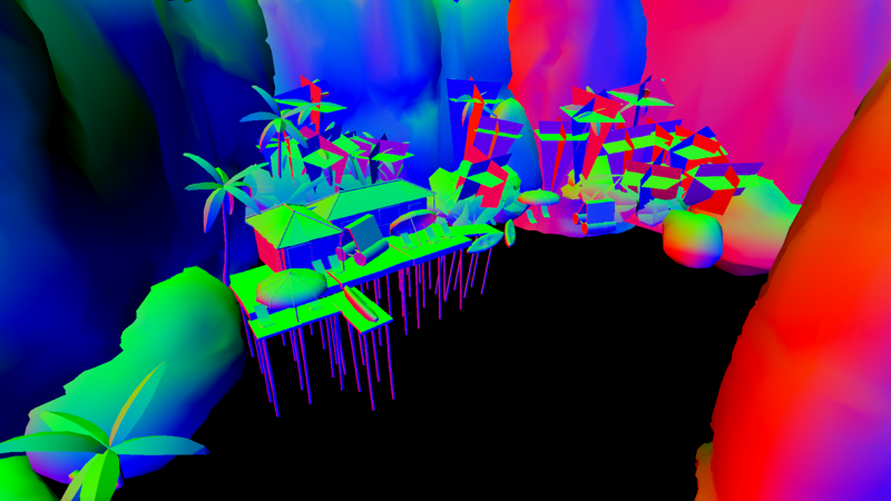
My materials have a visible seam wherever they're split into multiple polygons. Is there anything I can do in ShaderGraph to fix this? The meshes are generated programatically, so I can't easily merge them into one polygon.
This seems to be UV related : either fix your mesh generation code so that the UVs match, or use work space mapping in your shader (ex : us world position XY as UV input of a texture sample)
I mean, now they line up, but there's a new problem with them
It looks somewhat normal in one orientation, but perpendicular meshes have this stretched out look
And there's still some visible seam when it's not stretched, that I think has something to do with the lighting
Looks to me like it's a soft edge
Is there anything I can do about it?
hello everyone, i need some help when transforming world position into 'view position'; which i got working fine, but there i realized its not the equivalent to 'screen position'
so the question; what do i need to do to get a world to view transform act exactly as a normalized screen position?
[i need this effect urgently]
@spiral agate If you need the screen position you can use ComputeScreenPos(clipPosition), (where clipPosition is via the same UnityObjectToClipPos(v.vertex) you'd usually use in a vertex shader anyway), and in the fragment shader you need to do screenPos.xy / screenPos.w. This tutorial might also be useful : https://www.ronja-tutorials.com/2019/01/20/screenspace-texture.html
Ronja's Shader Tutorials
There are many techniques how to generate texture coordinates. Previous tutorials explain how to use UV coordinates and how to generate coordinates b...
I might be wrong, but it also look like you don't have coherent normals
@atomic glade ^
On the mesh itself? Definitely a possibility. I had to compute them myself so I definitely might have messed up the math
Any reason to not make it easy and let the recalculate normals do the stuff for you ? 🙂
How would I do that?
Ah, okay, it's a function of the Mesh object, not a shader thing. I'll give that a go
Definitely way nicer. I can live with this.
Any fix for the North/South walls having their UV's stretched out?
I'd need some way of uzing the Z of worldspace if it's facing one way, and X if it's facing another way
Test world normal, and branch Z or X depending on it
(But imho, it's best to have proper UVs in the mesh)
When I generate the meshes, I don't really have much info about where they'll end up in world space, they're from an entirely different program
Honestly, it's not too bad even without the UVs changing now that I've got the normals recalculated
@regal stag when do i use Computegrabscreenpos?
basically what i am trying to do is transforming refraction into screenspace, so i can distort my grabscreen UVs
any idea?
Uh, I think you'd probably use ComputeGrabScreenPos on the clip space position, and add/subtract something to offset/distort it. I tend to use URP/shadergraph so haven't really done anything with grab passes before.
hmm ok, either way, when transforming from world to object, then object to clip, then compute screen pos; or directly from OtoC, then copute screen pos
both do not look like they were in screen space
multiplying by view matrix and dividing .xy by .z gives a better result, which is what i had before i asked for help
In the fragment shader you also need to divide the screenPos.xy by screenPos.w
oh right, forgot that wait
well, i have no idea but its still not looking right
ok, i used vertex position as an input and its looking good, therefore i think i messed up something before i transform
a more general question, how do i compute grabscreenpos with this setup?
how do i transform and compute
refract( normalize( -worldViewDir) , WorldNormal , _RefractionIndex )
into normalized screenpos
@regal stag ?
@amber saffron
Test world normal, and branch Z or X depending on it
How would I do that? I've got the branching working, but I'm not sure what about the world normal I'd be able to use to know which is which
@spiral agate Sorry I'm not sure, refraction is bit too advanced for my shader knowledge, someone else might be able to help though
solved
had to transform view into clip, then multiply and offset by 0.5
not sure if that was necessary, but got it alligned now 100%
@atomic glade Branching on something like abs(worldNormal.x) > 0.5 might work. If the normal is pointing in the x direction it'll be true, so use position.zy, else use position.xy.
Hello, I am trying to implement vertex colours into my URP shader.
I've duplicated LitForwardPass.hlsl and added COLOR to the Attributes struct
But it is blank, does anyone have a solution for this?
Thank you
I was doing something similar, I was comparing to zero. Trying it with 0.5 gives me this odd shape here, and the perpendicular walls are still stretched
@amber minnow How have you determined that it's blank? How are you using it in the shader?
@low lichen I added a Color field to the Varyings struct
Then I set it in LitPassVertex
To display it I multiply color.rgb in LitPassFragment
If I do output.Color = half4(0,0,1,1) it comes out as blue, so it does work
Are you sure your mesh has vertex colours?
@regal stag Certain, I flicked over to another VC shader and it's there
@amber minnow Okay, I take it you are also using the Varyings Color in the fragment shader?
That's right 🙂 @regal stag
your caseing doesn't match
your struct uses color but your function uses Color
i would just double check that you have all of it matching
also where are you passing the attribute into your varyings? to make sure it goes through correctly?
oh sorry, my brain is very slow this morning 😴
ignore me haha
They have color in attributes, and Color in varyings, and seem to be passing it through fine, so as long as there aren't any shader errors and it's actually being used in the fragment I assume it should work.
Ah, the case mismatch doesn't seem to make a difference.
are other varyings coming through fine or is it just color that isn't working?
Position, UV etc are all fine
The case mismatch would only cause a compile error if you tried to use Varyings.color rather than Color.
yeah i see that now, my brain just wasn't parsing the text very well
i need some more coffee
Can you show where you are using the color in the fragment shader?
Sure 🙂
Adding input.color = half4(0,0,1,1) before that, makes it blue, so it seems to be working
Ah yeah
I have changed them both to be lowercase 🙂
what's the output you're getting vs what you expect?
What if you just return input.color for debugging purposes, does it show the vertex colours properly then?
@meager pelican So I looked into using the stencil buffer to make an outline like you recommended and I managed to get this result. I still have a few issues i can't figure out though.
- I'd like to use the standard surface shader to render the original object (im thinking i might have to use 2 materials to get this to work)
2. When the object goes behind another object it shows the full silhouette, I'd like only the outline to show.I figured this one out - I'd like to blur the outline, from what i've seen this has to be done with post processing using 2 cameras like you or someone else mentioned.
@amber minnow have you tried multiplying the surfaceData.Albedo by input.color before it goes into the FragPBR function instead?
that's how shadergraph handles vertex colors /shrug might make a difference idk
Will give it a go, thank you
is there a way to blur grabscreen within a single shader?
how does grabscreen work? are mipmaps generated in real time?
REPOST: Hey, I noticed that my build size has gotten quite big, so I checked the build report. Turns out shaders take 47.1% (61.2mb) of the complete build size. That's too much I guess. Any idea how to reduce the amount that shader (variants?) take up in the build? Btw. it's for mobile. Thank you very much 🙂
@golden crest I've talked about so many outlines, I've nearly forgotten the original context. But thoughts:
- You can use multi-materials, just draw the outline second if you're in the opaque queue, so it can depth-clip and avoid the extra work. Then you can sue the Standard material on the first shader. I think.
- you don't need a 2nd camera for post processing, in and of itself. It's a separate pass or passes after all the other stuff is done.
wont it blur the whole scene if i do it with the same camera? i dont really know what im talking about though
@spiral agate You can fake-blur it.
You'd sample and average pixels over some offsets as desired. I think the Unity force field demo might do that.
@golden crest Yeah it will unless you can write a custom post process, and just blur the stenciled area. Or fake-blur like I just to a.v. above.
yeah, i thought grabscreen was generating mipmaps so i could get some use of it, i guess i have no other choice than offset samples by myself?
ok i will try to figure that out. you've been super helpful btw
IDK, but you could try sampling with LOD. tex2dLOD takes a mipmap level
IDK if that's in SG off top of my head.
@spiral agate
@atomic glade better for you if you don't want the hassle of mapping yourself : use the triplanar node
I am really tired over how I've done this cast shadow thingy, when the object is invisible
I've tried using Shadow Only
but it doesn't cast a shadow
It casts this https://gyazo.com/80d0afc6458bd096da1bdbe7c0f1842a

How do I make something cast a shadow specifically by one certain light source?
So the monster only has a shadow when I use my flashlight but otherwise not.
That way I can have normal shadows but a "special" shadow for my monster design
Can someone DM or PING me so I can find it tomorrow, cause I gotta sleep got school tomorrow.
@amber minnow you remaking osrs?
@devout quarry Remastering yeah 🙂
You have a website for the project or something?
Sure do, https://www.youtube.com/watch?v=XMz58ygBDiE
https://www.youtube.com/watch?v=KczXejPoOFc&t=1s

Go to http://www.squarespace.com/sirpugger to get a free trial and 10% off your first purchase of a website or domain.
Totty's website (has link to discord there):
osremastered.com
What era of RuneScape graphics is your favorite? What do you think of the unity client's graph...
First impressions of Old School Runescape OSRS Remastered
Best video editor for Youtube beginner #Filmora (Windows & Mac): https://bit.ly/3dACKCO
Video editing App: FilmoraGo (Android & iPhone) https://bit.ly/3fwoCMK
Professional video editor #FilmoraPro: https://bit.ly/3fFdS...
ah damn so that's the one haha, okay cool, don't want to go too much off topic in here but nice project
Thank you 🙂
Is it possible to create a shadergraph in order to better control the density of the volumetric fog ? 🙂
Hey Everyone! I needed some help with shader coding. Specifically, I am trying to implement an extended version of the GGX shader in Unity as per some data of materials.
Any help would be greatly appreciated!
As of 5.3, Unity's BRDF is already GGX, so if you're extending it I'd look to customizing the standard shaders and/or custom lighting models for whatever pipeline you're using.
@meager pelican Thanks for the response! I read about that on the manual. However, the data I am trying to fit doesn't exactly conform to the standard shader, so I am researching on extending it. However, I haven't found any source for the standard shaders (and whenever I try to create a new shader, Unity in URP/HDRP always returns a pink material no matter what). Am I always forced to use the normal 'Create 3D project' and secondly, is there a source available for the standard shader that's all in one place?
How could i get the vector from the camera pos to the vertex pos
I'm trying to get the grass to part as the player is walking through it
Subtract them.
@soft harness
@simple tartan Unity's standard built-in pipeline publishes shader source here: https://unity3d.com/get-unity/download/archive (see the drop down box). The URP/HDRP I think are on git-hub here (But I've yet to dig into this like I should): https://github.com/Unity-Technologies/Graphics

Unity
Unity is the ultimate game development platform. Use Unity to build high-quality 3D and 2D games, deploy them across mobile, desktop, VR/AR, consoles or the Web, and connect with loyal and enthusiastic players and customers.
GitHub
Unity Graphics - Including Scriptable Render Pipeline - Unity-Technologies/Graphics
I did that but....
            v.normal *= dot(viewDir, worldNorm) > 0 ? -1 : 1;
            v.vertex.x = lerp(sin(_Time * 15) * max(0, worldPos.y - -3.379522), v.vertex.x, 0.99) + VertxVector.x / 5;
v.vertex.z = lerp(sin(_Time * 15 + 5) * max(0, worldPos.y - -3.379522), v.vertex.z, 0.995) + VertxVector.z/50;```this is my desired result
sub graphs: Manual mentions "dynamic data types" for when you want a port to change between (for example) vector1/2/3/4 depending on what vector type is input https://docs.unity3d.com/Packages/com.unity.shadergraph@7.3/manual/Data-Types.html
but where is the option for this? the blackboard only lists the non-dynamic types:
@meager pelican I subtracted them, but when i add the vector to the vertex, it doesn't give the desired result. Am I going about this wrong?
Set the alpha to non-zero. (err....maybe it's already 1)
And not-black? as a test
Maybe expose the color property, and for emission check lighting settings. In some systems you have to add the emissive color to the albedo color for the object's base color.
Can I expose the input to a Sample Gradient Node as a property? It doesn't seem like I can. I'd be happy even being able to set it via script. If none of these are possible are there any alternatives to get the same functionality?
@soft harness IDK, haven't done this. I might be inclinded to displace it according to a distance calc from the player's pos that would be passed in, or from camera-pos. But then it would be radial. Maybe father is less displaced, closer is more displaced, up to some threshold.
But otherwise, you want something orthogonal to the vector you asked about.
@waxen jackal Also found this:
https://forum.unity.com/threads/no-emission-with-shader-graph-in-lwrp.704159/

Unity Forum
If I create a material and associate a new PBR shader graph I can set the emission, and the object will be brighter, but it will not actually emit any...
How would you do that?
distance?
there's a distance function in shaders and of course SG nodes. Maybe use an abs(distance(myVertex, theCameraPos))
And then maybe invert and/or scale it somehow. Whatever math you want to invent for it. Lerp between amounts if you want. IDK, I'd have to play with it.
New to shader graph. Seems to be a lot of limitations. Does anyone know of any good examples PBR shaders with transparency?
Not looking to copy, only to learn.
there is a master node for URP/HDRP out of the box that does this?
not sure what an example would even cover
Well, there seems to be a lot of draw issues right out of the box. You can't do multiple passes for example, can you?
no, but that's a fairly specific thing
no custom master nodes was a huge mistake, don't get me wrong
I'm sorry, what do you mean? Using custom nodes is a mistake?
no, being unable to create master/"output" nodes
covering things like multiple passes or custom lighting models
Okay? I'm really new to shaders. I feel like unity is pushing this LWRP but there are so many custom things I can't do with it.
Maybe I should disable, and go back to learning how to script the things I want.
sorry to vanish, phone call
one of the classic examples is folks asking how to implement cel shading and similar stylized lighting in shader graph
that's something the Unity solution falls completely flat on its face dealing with, and I'm amazed Unity project management thinks throwing a hacky custom node solution on the official blog is an adequate workaround
I can understand there being complexity in actually implementing a custom master node, but that really shoots a lot of asset store creation folks (and just plain tech art/programmers) in the foot
it's not like you can't actually write everything in HLSL anyway, you just need to tell your art team they can't use a tool they like and to Deal With It™
Hey everyone, quick question: Is it recommended to use the normals passed in from the vertex shader in the fragment shader or should we multiply it with the Object2World matrix?
and also could someone explain why this is being done:
float3 LightDirection = normalize(lerp(_WorldSpaceLightPos0.xyz, _WorldSpaceLightPos0.xyz - world,_WorldSpaceLightPos0.w));
vs
float3 lightDir = _WorldSpaceLightPos0.xyz; // Light Direction
@soft harness OK, so I was thinking about your question while watching a crappy movie, because that's what you do during crappy movies....think about GPU stuff...and I was wondering if you need it to be "sideways" or not.
But if you do, then take the camera's forward vector (or calc it), pretty sure it's a shader variable. And then project the vertex depth into the scene with that vector. So cameraPos + vertxDepth * normalize(cameraForward) and then subtract that from the vertex pos and you'd get a vector, normalize it, that you can scale by its distance to that first point. But it would point sideways at the right angle. I think.
Then you can decide how much of that to use as a vertex offset. And maybe scale that by distance too if you want so it doesn't part like the Red Sea all the way to the far plane. Or something. 😉
So the closer it is to center, and the nearer, the further you "push" it either left or right.
Or do some math in screen-space, or view space instead.
my normal map is acting weird
your normal map is probably fine
your tangent space basis might not be
looks like problems with mirroring
What does that mean?
also i think it's my custom shader
                fixed4 e = tex2D(_EmisionTex, IN.uv_MainTex);
                fixed4 b = tex2D(_Bump, IN.uv_MainTex);
                // Metallic and smoothness come from slider variables
                o.Metallic = _Metallic;
                o.Smoothness = _Glossiness;
                o.Albedo = c.rgb;
                o.Alpha = c.a;
                o.Emission = e.rgb* _EmissionIntensity;
                o.Normal = b.rgb;
clip(o.Alpha - 0.99);```When i change it to the standard shader, it works fine
how do i do that?
fixed4 b = tex2D(_Bump, IN.uv_MainTex) * 2.0 - 1.0
you might also need to rearrange the channels if you're using compression on the image
still not working
what does it look like
TSB stuff might still apply, the seam in the middle is one of the classic giveaways something's wrong in that dept
especially considering it looks like one side is inverted
handedness change from mirroring one side and then blowing up the tangent/bitangent when you import the mesh into unity could do that
                fixed4 c = tex2D(_MainTex, IN.uv_MainTex) * _Color;
                fixed4 e = tex2D(_EmisionTex, IN.uv_MainTex);
                fixed4 b = tex2D(_Bump, IN.uv_MainTex) * 2.0 - 1.0;
                // Metallic and smoothness come from slider variables
                o.Metallic = _Metallic;
                o.Smoothness = _Glossiness;
                o.Albedo = c.rgb;
                o.Alpha = c.a;
                o.Emission = e.rgb* _EmissionIntensity;
                o.Normal = UnpackNormal(b.rgba);
clip(o.Alpha - 0.99);```looking a bit better, actually
just because, are you using the 'import tangents' in the mesh settings or calculating them
could be worth hitting that switch just to rule it out
whoop, you're double applying the normal unpack
o.Normal = UnpackNormal(b.rgba); will probably render fixed4 b = tex2D(_Bump, IN.uv_MainTex) * 2.0 - 1.0; redundant
yeah that sorta works!
also is your custom shader designed to work with tangent-space normal maps?
the mostly blue kind
I think?
there should also be a matrix multiply on the (unpacked) normal if they're in tangent space. Not sure if you do that somewhere else in the shader
the relevance to the mesh normal/tangent might make more sense looking at that
Unity does that for you according to docs, so you're off the hook
So, how do i controll the intensity?
lerp the normal to (0, 0, 1)
half normal = lerp(float3(0.5, 0.5, 1), tex2D(_Bump, IN.uv_MainTex), _NormalIntensity);
what do you mean, after unpacking?
o.Normal = UnpackNormal(b.rgba);
you would also change the other part of the blend from float3(0.5, 0.5, 1) to float3(0.0, 0.0, 1) if you do that
at some angles it turns black
i'm having a weird issue with bloom, i have a projectile that glows, and whenever i fire it the entire screen slightly illuminates, which i would like to alleviate
i tried reducing the blend distance as much as i could without completely dimming the object, but the effect was still there
it's only present for a frame or 2 but still noticable
it makes sense for that to happen.
If it's close to the camera of course the whole screen is gonna light up for a split second as it flies away
it's called laws of physics.
This was linked in #archived-resources, perhaps it's worth pinning here?
Unity’s Scriptable Render Pipeline represents a great advance on the way that unity deals with graphics, giving more power to the users to customize the pipe...
@vocal narwhal
it's already pinned
Oh sorry for the ping then
I tried checking but as soon as I opened the pins window my Discord froze 😅
Which Shader Plugin should I Use?
not a fan of writing things to get a Shader
I'm okay with writing code, but Shader is a no no
Start with shadergraph, see how far that gets you 🙂
is there a way to create a worldspace uv'd material with shadergraph?
Hi,
I'd like to port a few materials/shaders from Unreal to Unity (Standard Pipeline), which would follow this basic pattern:
Textures are mixed, or have only certain color channels used, and the output is passed to something like the standard shader as inputs.
I assume this could easily be done with shadergraph? but any ideas how to do with the standard pipeline? Or tips how to approach this with standard shader code? It would be great to have something like: 1 shader that is basically the standard shader, but is included in all the other custom shaders. And the custom shaders are just responsible to changing the input that is passed to that shader code.
(Although this might not be possible or reasonable, since different materials sometimes have more or less texture and regular value properties set)
https://cdn.discordapp.com/attachments/438387938947235840/712224352015482951/Unreal_Material_M_Barrels02.png

@strange sonnet Position node -> Split -> put the components you need depending on direction of uvs into a Vector2
thanks!
Or use the triplanar node
@dim sequoia If you're working in the built-in pipeline, check out Surface shaders...they generate custom lit shaders. "Just" translate that graph to code in a surface function.
thank you! I'm trying that now 🙂
seems like the right node isn't really an equivalent of the standard shader (what I thought), but of a surface shader output like SurfaceOuputStandard, will use that now
do you have an idea if it made sense to have some reusable shader code with this use case, like with cg includes?
Maybe it doesn't make sense because difference might be too big,
Uh, IDK how to answer that, depends on your use case. But you can certainly do CG includes.
As to "the right node" you mean the master-node in a graph compared to the variables in a surface shader? They're actually not all that different for most of it.
In the picture I posted above, the node called "M_Barrels02" - when you make a material in Unreal Engine - it seems like I had a misunderstanding, this is like the surface shader output,
somehow I associated the node with a full Standard Shader instance before
but yes, I guess it depends on the use case, I should check the other materials and see if there is repeating logic for modular code, thanks again
Dayum Unity Shading is so annoying, now the shadows aren't showing after I installed the Pipeline

I want an invisible thing, which cast a shadow
I know I could do it with Unity itself, but I had this problem where you could still see the object when you shine a light on it for some stupid reason
I guess I'll just remove the stupid Pipeline, and then try stuff around
else I'll just not care
Look at this, it shouldn't do it like that. It should only show the shadow on the walls
and floor
not itself

Unity it works perfectly fine
aka editor, but in the game it doesn't
@latent veldt Unless I'm misunderstanding, It looks like it's working fine to me? Your light source and camera are close together so the shape of the shadow is going to look like the capsule in the game view.
I think it is already casting on just the walls and floor.
you can make invisible shader that casts shadow
@regal stag the intent is that the capsule itself doesn't show
I don't know how to use Shader Graph for that nor do I know how to do the Shader stuff
which SRP this is?
yeah, I get what you want
you want only shadow, but not mesh rendering for the capsule
Ye, cause if I walk around it. It just looks like a completely black 3D Model you can look around
idk how to use Shaders at all, cause I only like to do the programming part
but cause I am working only with me as the main and then my friend is 3D modelling It's hard to do the other weird things.
I've never done this on SRPs but I know there used to be a sample shader in old Unity wiki for the built-in
you never said which renderer you use

@fervent tinsel In the video they posted I think the capsule is already invisible though. You can see when they turn around it doesn't show where the skybox is. That capsule is the shadow? Right?
The thing is, it doesn't cast like this in the Game View https://gyazo.com/f87d5ed627c598a3318c00009c1cb2a7
the links
From the camera's point of view, that shadow will just look like a capsule
I know
Cyan call me, I'll share screen
we will be muted so I can show my screen
Cause no one understands me, I've had the same problem yesterday
and people can't see what I'm seeing for some reason
my friend can doe
I don't do calls, you'll have to try to explain it here
I literally did
in game view it's like a 3D model with the shadow when I walk around
but inside the editor view it works perfectly fine
Your light is attached to the player + camera right
Attached to Player, Camera, Item Holder, Flashligt, PlayerLight(Light itself)
Right, but with the light being at the camera's position, the shadow being cast is going to look a lot like the capsule.
Look, it looks like a 3D Model which is just all black. https://gyazo.com/0b9e7a32a445fa0bbff26ecfe5a99f24
Else, I guess that's how Unity works.
You probably just need to adjust the light position so it isn't so close to the camera. It won't look entirely accurate in terms of where the flashlight model is, but perhaps that will give you a shadow being cast in a way you prefer
Okay, thanks :)
From what I see, the "black model" you see it the shadow projected from the "shadow only" capsule, right ?
Yeah, you're just looking at the shadow from the light's perspective, which makes it look like the original capsule shape.
So this is somewhat expected
I just want to share something y'all probably already know: the depth buffer used by shaders is not the same as unity's camera depth texture - the latter is controlled entirely by the shadowcaster passes of your shaders
This really helped me out for a postprocess outline effect on my 2d game where I want several things occluded for no reason
The new shader gui support in shadergraph is nice, but still I'd love to see an easier way of just splitting variables into groups with a header on top
just for organisation
@devout quarry I think thats on our roadmap? I can double check
do you mean in the actual shadergraph or in the material inspector?
I mean the material inspector
This is nice, but would be cool if it would be the same in the material inspector
Just something basic like this
I think the goal would be to have a basic material inspector that did that sort of thing
so just grouping properties and having a little lable on top
as part of those two
right, we would like to have the basic material inspector be nice like that, but also pipelines override the inspectors often
so like HDRP would need a way to generate those as well, based on the info we provide
just gets a bit tricky
Ah right that's true
Anyone know how sprites and shaders work together? I got a script that successfully assigns a texture to a material, but the actual texture isn't appearing on my sprite. I'm 99% sure it's something wrong with how I'm setting it up in the editor.
I'm using a sg shader.
I tried three things:
- A circle sprite with full opacity, and the custom material assigned to the Sprite Renderer. Nothing happens, sprite stays a white circle.
- Make a child sprite renderer for the circle sprite, make it have no sprite assigned, but the custom material (now unassigned from the main sprite object). Still circle stays white and nothing appears on top of it.
- Use the experimental Unlit Sprite Graph instead of the normal Unlit Graph. Same issue
Sorry to complain on a public chat @simple frost , but I already asked to the team some month ago the ability to override the material inspector using a custom scripted one. This could be as simple as adding a string field in the blackboard, to change the value set at the end of the generated shader (CustomEditor).
@amber saffron this works right?
on the master node you can provide a class that overrides the GUI?
Ok, sooo, my bad, I missed that apparently !
Not clear to me why it's on the master node gui and not the blackboard directly
@molten halo Shadergraph should use a texture with a "_MainTex" reference in order to obtain the sprite texture from the SpriteRenderer.
I already stated it assigns the texture successfully
I have a _MainTex reference
when I double click the material instance on the Sprite Renderer (in play mode) the texture is there.
Okay, you shouldn't really need a script to assign it though unless you are creating the sprite renderer at runtime I guess. You'll probably need to share an image of the graph so we can help
I'm assigning one of two textures randomly, that's why I use a script
I'm also gonna be doing the same with the colors
I see, are you assigning the texture using the material.SetTexture or SpriteRenderer.sprite?
Note that I suggest to use one of the channels (r) of the texture sample instead of the whole color, or might end up with weird results if you don't plug a greyscale texture 😄
Well I'm only planning on assigning grayscale ones. Cause I'm coloring them inside the shader.
@regal stag SetTexture
But the sprite renderer overwrites it
Yeah, the SpriteRenderer.sprite will override _MainTex, so you should set it on the sprite renderer if you want to swap the sprite out
If it's just to overlay a texture on an existing sprite, use a different texture reference
like what?
Originally I was getting a warning in the Sprite Renderer cause I didn't have a "_MainTex" reference.
The shader needs a _MainTex reference to pass the Sprite through from the SpriteRenderer, but technically you can still leave it blank and unused if you don't need it
k, i'll try that
If you aren't actually using a sprite (or it's sorting layers, etc), you could probably just apply the shader to a quad instead too
works great, thanks!
Does it matter if my image file is Default or Sprite? Both seem to work.
If it's set to sprite, then you could probably set the spriteRenderer.sprite variable instead of using SetTexture to pass it through to the shader. I don't know if there's any other differences though
I see, but if the shader isn't using the sprite's texture surely it isn't showing as a circle though?
right now I'm changing the texture like before, but using a reference different to _MainTex, and it works fine.
texture appears on circle, but doesn't change its shape
Ah okay. Maybe the sprite renderer's mesh is still producing a circular shape from the sprite. If it's not using the texture in the shader it might look a bit jagged though. You could also sample the _MainTex and use it's alpha.
k, thx again
whats the best way to fix this UV? Or would it need to be remade?
Reposting my question here as I think #archived-hdrp was the wrong one.
Hi folks,
I've got two gameobjects which are sharing a material and shader.
I want to be able to enable a boolean property on the shader per game object. So I'd have one chair with outline and one without.
How can I do this? Or am I going about this completely wrong?
I'd make two materials, one with an outline, one without and swap the materials
instead of changing the value
ya, since the value affects all objects with that mat
@dusky stirrup I believe you should be able to make the material value instanced, is this custom written or shadergraph?
@dusky stirrup What outline method are you using? Multi-pass or not?
or is it just that he's altering the value in edit mode and seeing it alter on everything, while each object will be have an instanced value in play mode which will not alter everything?
I went with the approach to swap out the materials. I'm using shadergraph for the first time though.
Any idea how I could make the outline always render on top of everything else?
Is there an easy way to do this via shadergraph?
I don't know if this a shader bug but shaders are flickering like crazy

Antialiasing was set to SMAA for this but it reproduces with no antialiasing as well.
Is there a way to cast shadows of a 2D tilemap onto itself (assuming varying Z values)?
nvm, I think I'm in the wrong channel xD
I doodled a quick tool to help you pack your textures into a single one : https://github.com/RemyUnity/CRT-Texture-Packer
Might be helpfull for HDRP Mask Map and Detail Map :)
Or any fancy shader optimisation that you might want to do.

GitHub
A texture packing tool made with custom render texture - RemyUnity/CRT-Texture-Packer
Sounds like what @grand jolt was asking about earlier today!
Had some external tools for that kind of stuff but with direct preview in unity mmm that sound nice
try setting the near clipping plane a bit further away
@grand jolt what are you using to texture? theres a mode in substance painter called tri-planar projection and it projects on the object rather than the uv
so it wont cut on the edges of the uvs
maybe theres a similar feature in whatever tool you're using
i am not sure if this is the right place, but why is the render texture showing a different thing than the camera?
i have no idea why this is the case
does anyone know why shader graph gives me this for a custom function?
happens if there's just one line Out = ...
@crisp trellis Have you added the "Out" to the outputs list on the node? It doesn't look like there's any output connection on the node
    Out = A + B;
}```the output connection is hidden if you don't press that tiny arrow
<
btw I'd really appreciate any help
I did read the forum posts on this searched for youtube videos that explained that
it seems like the docs are messed up idk
I'm a bit confused as to why your image has a uv(2) input but your custom function has a float3 and a float
cause i already tried a thousand different things 😄
also does + work with a float3 and a float?
guess it gets cast to a vec3
I'm pretty sure i did everything right by now (as in the tutorial)
Does anything change if you save, close and reopen the graph?
your file is a .cs
ya
needs to be a .hlsl
Well spotted
says text file in that tutorial i think
that should probably be updated then
err ok maybe it doesn't say text file
hm
nvm ignore that
give me a minute i'll tell you then
ya awesome @simple frost
it's gone now thanks
i would like to know that too
and ya it actually says hlsl file. but it's not clear that this is about the file ending
if the file ending is that important i think it should be clear
also thanks @regal stag for helping as well
@sonic bear what do you get when changing to "game" window
does color change?
HLSL is the shader language that you're scripting in, so when writing the docs we assumed that it would clear enough it needed to be a file of that script type. You can't put valid HLSL into a .cs file c:
@crisp trellis when entering runtime the render texture remains the same, different than what the preview shows
I'm not trying to be confrontational here. I named it .txt before because there is no reason to assume that file ending matters.
make with that information what you want
but if looking for the needle in the hay stack that information would be valuable : )
@crisp trellis file extension matters a decent amount
@sonic bear I just mean game window
so not pressing play
(btw sorry if I triggered someone by saying the docs seem messed up. I take that back)
@crisp trellis yes, changing what camera is rendering, changing culling settings, changing clipping plane distances, and switching to the game window changes nothing
What part is missing from the render texture?
the level, you can see the difference in the camera preview and the texture right?
that is the level
oh that
perhaps it's culled?
hm 0.01 - 70 prob not
or is it "inside the camera" perhaps?
If it was being culled I don't think the camera preview would show it either
ya
yeah i am clueless
solid black, you can see it in the camera settings
is there a reason you have different settings for those than the default ones?
(those are my defaults)
becuase i am trying to cut the resources taken by the minimap camera, the main camera uses one for shaders
ok
Yeah, usually for a second camera you might not want it to create a opaque & depth texture if it's not being used
the minimap requires blips to be shown, but they are on their own layer that the main camera culls out,
and also i dont want all the blood splatters to show on the minimap.
but again, if the camera was culling it out, why would t show in preveiw?
i mean you can have it mixed. but at that point i'd assume you cull some layers out
ok
no idea
Maybe it's something to do with the material/shader the level is using?
can you send the file?
only if you want
and if it's small
Certain parts like the red (doors?) are appearing fine on the render texture
no, the proget is like 0.5 gb
annd that is true! they are on the same layer and use the same shader as the rest of the level
ok. if you can and want to simplify the part that doesn't work that would be an option
honestly chances are some faces are wrong direction @sonic bear
perhaps camera preview and what you see in scene handle that differently
is the mesh created outside unity or a dynamic one?
here is the render texture
to check the face thing move the camera on the other side or turn the object around
Interesting, the icon for the render texture looks like it's capturing the scene fine. Perhaps it's just the shader that's rendering it to the UI?
And by "capturing fine" I mean it looks the same as the camera preview, but perhaps there's some unwanted alpha that's somehow there too
so it wont be backface culling - preview seems to do that as well
Maybe it's some kind of bug? Perhaps update lwrp/urp? I'm not too sure what else to suggest.
let me try changing the image or something
nope! nothing has changed
i am going to havea stroke
still dealing with it?
yep! why is the render texture in file veiw different from what the canvas shows?
i wish i knew
i'd try reproducing with simpler stuff if i was you
until you can isolate what's causing the bug or whatever it is
i had to change it to using a material rather than the render texture and now it works
i am angery
what is wrong
hmmm
hmm?
I see and I don't see
kinda
Are there currently any known bugs to shader graphs custom functions?
I am getting some error with undeclared identifier MyFunc_float
I can refactor my code though in a way that it goes away by inlining all helper functions and using it as string. which makes me think it's a bug
that black squar
and the map in front of the camera both use the same material
why is this broken
Can I expose the input to a Sample Gradient Node as a property? It doesn't seem like I can. I'd be happy even being able to set it via script. If none of these are possible are there any alternatives to get the same functionality?
OK, this is going to end up with egg on my face, I'm sure. But can someone help me debug this SG issue I hit? I was confirming a point
also does + work with a float3 and a float?
guess it gets cast to a vec3
@simple frost
and she's right and it does; it gets propagated into all the left-hand "slots". But I decided to play with it in SG, right? Because SG = fun, and I was bored, so I did this: