#archived-shaders
1 messages · Page 124 of 1
Also, such a question belongs in a different channel. Please don't post same question in multiple channels (aka: delete it from render-pipelines please)
yeah, i just realized that
Im sorry
done
didnt even find where did I posted originally
thanks for your help
how do I decide between
(1) passing the time to a shader only and doing calculations (relatively small, uv offsets there)
(2) calculating the few offsets I need on the cpu and set them as material properties
?
Do both. Make 1000 objects on screen. Test/time the results each way.
Some results are hardware dependent too. In general favor math over lookups, but YMMV.
P.S.
And when doing math, multiply first, add second as a general rule. Although shader compliers are better at optimizing these days, a MAD (Multiply add) ordering helps....many GPUs contain special instructions that can multiply then add all in one instruction. Many compilers used to be kind of stupid, and if you did stuff in the wrong order they wouldn't catch it, so they'd generate 5 whatever instructions where 1 would have worked. Some may still be "dumb". So remember MAD.
FYI
I'm posed with something I can't figure out. I'd like to encode the XY world normal direction as degrees, so I can pack it into a single channel (and unpack it later). My math skills are severely lacking, anyone know how to achieve this?
Sooooomething like this?
And what about the z value ?
(I was wondering the same)
I mean, only one angle is not enough for proper shading in 3D
@vocal narwhal Perfect, thanks! ✌
I only need a 2D direction, so this is fine. Need the other channels for other things
Does anyone know how I could achieve a cavity rendering post processing filter? Maybe its just 6am and its something easy i havint thought of, but i really love what the cavity filter as a viewport shader does in blender 2.8
Possible in unity?
@soft jacinth It's possible to derive a cavity/curvature map from normal map, so should be possible to apply it as a post effect by piping in the Gbuffer normals
You can use this (iirc the size parameter is for the texelsize/resolution) ```#define CurvStrength 2
//single channel overlay
float BlendOverlay(float a, float b)
{
return (b < 0.5) ? 2.0 * a * b : 1.0 - 2.0 * (1.0 - a) * (1.0 - b);
}
float4 CurvatureFromNormal(sampler2D normals, float4 size, float2 uv) {
    float width = (1 / size.z);

    float posX = tex2D(normals, float2(uv.x + width, uv.y)).x * CurvStrength;
    float negX = tex2D(normals, float2(uv.x - width, uv.y)).x * CurvStrength;

    float x = (posX - negX) + 0.5;

    float posY = tex2D(normals, float2(uv.x, uv.y + width)).y * CurvStrength;
    float negY = tex2D(normals, float2(uv.x, uv.y - width)).y * CurvStrength;

    float y = (posY - negY) + 0.5;

    return BlendOverlay(x,y);
}```
Is there a way to change a shader property at runtime on a UI element (RawImage Material/CanvasRenderer)? nvm, looks like i can use RawImage.materialForRendering and manipulate it directly with SetFloat etc.
so close! any solutions for the weird flipping between walls when coming closer/further?
Is there a way to keep this blur the same so no matter how far I'm zoomed out? I have an issue with a setup where I have the glass in a window frame and it blurs the windowframe when zooming out and ends up with a lot of artifacts
i used a gles shader inside GLSL Program but it does not behave properly
Is there a way to keep this blur the same so no matter how far I'm zoomed out?
The blur would change in the real world too. What artifacts are bothering you? The angle from your eye to the objects on the other side of the glass changes. Perspective changes. Imagine your eye a few mm from the glass as compared to across the room. Different angles and views on everything.
Maybe a different blur method.
Does someone have / know where I could find a hybrid cutout shader like this?
There's 2 thresholds:
cut threshold
opaque threshold
Between these 2 it uses full alpha
Above opaque, its opaque, and sorted properly
Below opaque, it's cut completely
How do I use the TriPlanar node in ShaderGraph to do two different textures? E.G. - Snow on top of rock and show the rocky material on the sides.
Hey folks. Does anybody know a resource or tutorial for writing a vertex shader that will animate a field of models so that they're like a field of swaying, billowing grass (probably with perlin noise)? I'm looking to replicate the Unity Terrain wind effect, but I'll be affecting a variety of individual meshrenders all over the floors, walls and ceilings of an environment.

Let's learn how to make realistic grass with Unity Shader Graph! This video is sponsored by Unity ● Download grass assets: https://ole.unity.com/grasssway ● ...
Hey, thank you @meager pelican Carpe! As it happens, I'm not using Shader Graph, but I'll take a look at the video anyway - will have some useful info! Cheers!
Yeah, you should be able to translate the ideas into non-spaghetti (real code). 😉 You'll have to add your own permutation of noise in there I suppose (I haven't watched that in a while, so IDR if he did that or not)
Any fix why is this happening? It's shaders problem.
4EverNoobys... I'm afraid I don't recognise 'vp' or the issue you're having in your picture. =( Another noob here...!
Folks, trying to follow this tutorial, but running into problems.. can anybody suggest a solution? https://lindenreid.wordpress.com/2018/01/07/waving-grass-shader-in-unity/
I'm supposed to be getting a response like this... https://cdn.discordapp.com/attachments/493511507192184882/622769825823064064/grass1.png
...but instead, my model is showing up as this: https://cdn.discordapp.com/attachments/493511507192184882/622770011139997696/unknown.png
I assume this is to do with the relative positions of the origins on the respective models. Presuming this is to do with world origins...
A tutorial on how to write an animated waving grass shader in Unity/CG.


that dog looks woke
I'm not sure that goes here but how i can make this lighter?
@reef spoke - true, very alert. =D
I'm making mod to game called "Yandere Simulator" but this hair shader is really bad
Hey guys, I asked this question in #✨┃vfx-and-particles as well,
Does anyone know how to make a custom node for the VFX Graph?
I know it's possible in the shader graph but was wondering if the same solution works for the VFX Graph
thank you !
@dreamy stone graphics look sick dude
(also if you have an answer please mention me so I see it)
I'm using a quad to display some vegetation
but my edge detection shader picks up the quad mesh because there is a 'difference in normal vectors' between the quad mesh and its surroundings
I don't want this, I only want an outline around the bush but not the quad mesh
does anybody have a suggestion on how to fix this?
Could I make the quad 'not write to the normal buffer' or something
with cutout / alphaclip it shouldnt
yes, if you actually have transparency in the Alpha channel
I do, but I can't actually have it be transparent
because then you see outlines of other objects
that are behind it
With cutout there is no transparencies, there is only solid and transparent
the stuff that fails the alpha test won't render to depth
and therefore shouldn't render normals into the normal buffer
the stuff that passes, renders to depth, and should
Looking at your first image, it looks like you had transparency, where the whole quad renders to depth
cutout/alpha clip should work fine, is your next image not that?
my 2nd image is Unlit/Transparent Cutout
Are you using builtin?
I should've mentioned, no I'm using URP on 2019.3
2nd image is when I change render queue to transparent
the outline of the quad is gone, but now I see outlines through the leaves of the tree
Does URP/Unlit with alpha clipping work?
nope
but the reason that the outlines are drawn around the quads
is because of normals, not depth
this is my debug view to check which outlines are drawn because of normals
and this is for depth
In builtin you can modify the depth normals shader and provide your own
I have no idea how URP works
how are you getting the normals texture? Is it a custom pass?
yes it is
https://pastebin.com/KLxrK96N this is the feature

Pastebin
https://pastebin.com/hy0Pipka this is the pass
Pastebin
hmm
I do use this in my script, I'm going to try modifying those filteringsettings, this is getting more #archived-hdrp than #archived-shaders maybe
let me try
You're providing the internal depth normals shader depthNormalsMaterial = CoreUtils.CreateEngineMaterial("Hidden/Internal-DepthNormalsTexture");
I remember this in the past
you've gotta copy the builtin shader, modify it, and provide that version instead
Actually, looking at the shader, it might perform properly already. It has a transparent cutout section that reads okay
It's probably a #archived-hdrp thing, you're right 😛 figuring out how to get the settings to match the shader. I've not touched the pipelines enough to know how to actually get it working ):
I am able to limit the objects that are drawn to the depthnormals texture
for example here the leaves aren't rendered to the depthnormalstexture
so now in my outline shader I get normals from this generated texture, with the leaves not writing to the texture
and I get depth from another depth texture
I hope this works
https://cdn.discordapp.com/attachments/497874081329184799/622884546542567424/unknown.png How i can fix this hair shader?

You'll need to define "fix"
#define FIX
Haha, that's an alternative to the "Make it look pretty" magic button !
Hi! In shader graph, how can I get the camera normals texture? Thanks!
I've been told it's possible to do using shaders, and I've come close a few times. But i'm looking to create the following effect:
- Using stencils
- URP and render features (but I an answers how to fix it with custom material shaders is also fine)
- I want the "purple man" to be always visible behind objects of a certain layer.
- Other layers should not be hidden (gameplay cover objects)
hiding the blue is not an issue, but I need to draw the green part , which is occluded by the blue "roof"
the green represents the wall/floor behind the object
so my strategy was to
render the scene
render the stencil (green) (ref = 1)
render the building (blue) (ref !=1)
render the building BEHIND the stencil (ref = 1, depth???)
render the objects (sorry for the wall of text, i've been trying to fix this problem for 2 weeks now)
@drifting edge This might help:
https://www.youtube.com/watch?v=szsWx9IQVDI
he does the "behind stuff" thing.
Let's learn how to render characters behind other objects using Scriptable Render Passes! This video is sponsored by Unity ● Download Project: https://ole.un...
Thank you, I started out with this video. I have set it up fairly similar similar however he does not address this specific problem. He puts objects on top basically, I need to be able to "punch a hole" and render what was behind it.
OK, then you need to have all objects honor some mask when rendering. Or render in two phases/layers, and combine with mask.
Basically, not render those pixels. But you'll also have backface culling problems.
this is the closest I've got, but it was mostly working due to "luck" I think, not an actual working solution
I would just render it like in the brackleys video, but the problem is that the gameplay relies on seeing the NPCs behind cover in a building
for other people interested, this seems very relevant
https://forum.unity.com/threads/see-through-system-shader-independent-visibility-obstruction-handling.278594/
Unity Forum
[ATTACH]
See-Through System provides an easy and highly configurable way for implementing partial transparency in your projects. Use it to make your...
I understood you then 2nd time. 😉 Yeah, that's the multi-pass approach. And I'm not sure, but it looks like you need to do special things for dealing with backfaces or other "hidden" stuff.
The normals on the backside wall in your example are facing AWAY from the camera unless it's doubled-up. You can draw them double sided, if lighting/shadows aren't a problem, but otherwise you'll need to double-up your geometry in your mesh editor to have double-polygons (basically modeling the inside too). Or the back inside wall won't show.
But yeah, that's the multi-pass approach. That asset won't work (from what I read) right now on SRP, but he described what he did on the first page.
So what's your specific question? I mean, we can't code the whole thing for you. Not being snarky, but, if you want to post some code and ask "why does this code do that" it would help.
Otherwise, I'd go with his description. Or buy the asset and reverse engineer it for your game (modify it for your use).
At this point I would accept any verbal abuse as long as it solves the problem 😁. Your explanation is already very helpful thank you. I'm an experienced programmer, but I lack experience with Unity/3D programming. So let me see if I understand correctly.
- By "doubled up" do you mean that instead of having the room as "one cube" it would have to be multiple cubes? because right now each wall is it own seperate game object 3D cube.
- I saw the issues with shadows, so I decided to compromise and turn them off for now (the games art style is not decided anyway and might be very simplistic in the end)
- My approach has indeed been multi-pass (I think). I use the URP and seperate the involved layers to seperate renderer features (like the Brackleys video).
- The linked asset thread is interesting but I do not understand some of the concept he mentions like " trigger-obscurance mask using triggers and obstacles z-buffers" ( i feel like this is the part missing from my solution)
- The actual question would be: how do I render the green circle, the part that is behind my stencil? I think I understand how to leave out the part that is in front of it.
- And maybe also to verify that the rendering strategy from my original post would make sense
No abuse meant.
Doubled up....for any normal triangle you'd have two: one facing backwards towards the skybox as the outside wall and one on the inside of your "room". Then their normals would face the right direction for lighting calcs (like a lamp inside the room in your example).
You MIGHT want to wait for more input, but I'd consider having a "standard" shader that supports your effect...and use that for all stuff that's to have see-thru ability. And then use masks that it would honor, and check the depth against your rendered effect (calced?) so it would draw what is "behind" him, or if drawing him, draw the glow and the character somehow, but if not masked then just draw normally. Maybe (I repeat maybe) you can do it in one pass.
Not sure, kind of talking out of my butt here. But I hope this helps some. I think whatever you do, you're going to have custom shaders.
The "green circle" is probably a post-effect for the stencil mask. Guessing. Maybe you can pull it off if it "knows" the stencil area is the only thing showing in your special-shader. So whatever you're drawing, if it's stencil, it's "green" blended? Again, just spit-balling.
And of course there's probably a stencil pass unless you can use structured buffers and calcs for the circle/ellipse.
Yes I think I've read about those blending modes that that would be worth a shot actually. Many thanks for the input! Will give it another shot tomorrow. Any other feedback welcome dear shaders experts!
Or maybe a secondary depth buffer instead of a stencil. Hmmmm......
@drifting edge i was trying to make an example of the stencil you're after, but it leads me to believe the LWRP depth "prepass" is wrong, it isn't a true depth prepass and doesn't keep the depth assigned
I'm seeing if I can get it to keep the prepass depth assigned as that is required to Zfail the stenciling mesh
The depth pass in LWRP seems to just be for writing _cameraDepthTexture but subsequent passes write into a temporary depth
I'll get it sorted out tho, I think they need to change or add some functionality since the depth pass is misleading.
If it was a depth prepass opaque only has to ztest Equal, and any stencil pass would occur between depth prepass and opaque
And I should mention that if you're blending that green color over the background underneath, basically doing transparency...that's IF that's how you decide to do it by using blending rather than changing the rendering color directly when drawing the 'background'...transparency is already a different pass.
@uncut karma https://forum.unity.com/threads/when-we-talk-about-z-efficiency-is-it-for-depth-or-shadow-pass.665014/ do you think this thread is relevant? Also thank you @meager pelican every small idea helps because it allows me new research paths to learn more about this problem.

Unity Forum
DrawMeshInstanced API doc mentioned the batch won't sorted for Z efficiency.
I am wondering if it means:
- overwriting Z buffer (basically instances...
I think every thread I've seen about something related to stencil buffers, z-depth or LWRP had a very good comment from bgolus, I might have to try to also get his opinion.
There's a concept with GPU's called "early-z-test". It is, from our perspective, in hardware/firmware, built into the pipeline. With early z testing, any fragment with a z-value that won't pass a z-test is simply not processed at all in the fragment shader stage. It's "clipped". This is why opaque stuff is drawn front-to-back (close to far) so big objects (big 'ole tree next to you) can clip all those little triangles behind them.
There's also manual, in-shader, testing that you can do.
You'll find the ztest on|off setting in shaders. Transparent stuff is different, and usually expensive, since it IS often processed per fragment with ztesting off or at least zwrites off. Which is why overdraw is a problem.
https://cdn.discordapp.com/attachments/497874081329184799/622884546542567424/unknown.png How i can make this hair look normal?
@dreamy stone Do you have an example of what you're looking for? You didn't specify how you wanted to "fix" the hair last time
Well, the blond girl in the front seems to use this texture, and the hair seems to render a color similar to the texture sooooo ... I don't get the issue here
@dreamy stone I'm a noob, but I would like to try to help: is it possible that unity is creating shadows for you in the hair, but you yourself also have drawn these shadows onto the texture already, making them your shadow + unity shadow = double shadow?
This hair have to be lighter
Hey, how do I add the Emission global Illumunation option to my custom shader?
@dreamy stone do you want to fix it by painting the texture or by programming a shader.
You can try an unlit shader
I want to try changing shader
I uh... want to do a specific kind of thing with shaders, but I've never actually coded shaders before so idk if that's possible with Unity
Basically I wanted to render 3 passes, 2 unlit and 1 with basic textureless lambert lighting, and use the lambert pass to blend the 2 unlit passes together
Although... If I could use the results of the lambert pass to determine the results of a single unlit pass, that would work better
...Will posting a picture of what I want to achieve help?
How would I amend the SubShader so that the Cube property is blended with the MainTex?
Here's the plaintext if you want it ```Shader "Cg shader with reflection map" {
Properties {
_Cube("Reflection Map", Cube) = "" {}
_MainTex ("Texture", 2D) = "white" {}
}
SubShader {
Pass {
CGPROGRAM
     #pragma vertex vert
     #pragma fragment frag

     #include "UnityCG.cginc"

     // User-specified uniforms
     uniform samplerCUBE _Cube;

     struct vertexInput {
        float4 vertex : POSITION;
        float3 normal : NORMAL;
     };
     struct vertexOutput {
        float4 pos : SV_POSITION;
        float3 normalDir : TEXCOORD0;
        float3 viewDir : TEXCOORD1;
     };

     vertexOutput vert(vertexInput input)
     {
        vertexOutput output;

        float4x4 modelMatrix = unity_ObjectToWorld;
        float4x4 modelMatrixInverse = unity_WorldToObject;

        output.viewDir = mul(modelMatrix, input.vertex).xyz
           - _WorldSpaceCameraPos;
        output.normalDir = normalize(
           mul(float4(input.normal, 0.0), modelMatrixInverse).xyz);
        output.pos = UnityObjectToClipPos(input.vertex);
        return output;
     }

     float4 frag(vertexOutput input) : COLOR
     {
        float3 reflectedDir =
           reflect(input.viewDir, normalize(input.normalDir));
        return texCUBE(_Cube, reflectedDir);
     }

     ENDCG
  }
}
}```
Being able to modulate it with a color picker would be chill too
A single shader has been compiling/optimizing on an il2cpp build for over an hour now
I must have attatched it to the wrong mesh
are these (300,000) vertices?
If so this is about to be trippy
can anybody tell me the last version of Unity supporting precompiled shaders?
@mossy smelt disable "Optimize Mesh Data" in player settings. It's kinda broken for SRPs in all but the latest betas
@grand jolt look at other examples how to sample texture 2D. Sample both in the frag function, and instead of returning texCUBE return e.g. myCubeColor * myTexColor. You'll have to play with how you combine the two (multiply, add, other custom blend functions,...)
is there a way to render something to texture and save it without having to instantiate an gameobject?
i wanna render a planet that consists of tens of thousands of tiles and save it as a texture, but having to instantiate them takes too long, i also need to be able to apply shaders to the tiles when rendering
Guys, how do I convert ASM shaders (Precompiled Shaders) to GLSLPROGRAM?
all of my precompiled shaders is GLES
so
im still figuring out how to convert them to GLSLPROGRAM
shaders thats from Unity 4
Lemme guess, Yandere Simulator?
Good morning! Still having the same issue as yesterday... Basically I have 2 base color textures I want to use on an object, one to use where the object is lit, one to use where it's not lit. I was thinking of having my shader make two passes, a first lambert pass, and then a second unlit pass that would blend the two textures based on whether or not the shadow from the first pass passes beyond a certain threshold.
My end goal is to have something similar to this
I've been reading a bit these past few days about Shaderlab to figure out if I could do this, and well, I figured that I could use the pass instruction to make my shader have multiple passes, but I haven't yet figured out how to get the result of the last pass for the same given pixel
Best I could find was the Blending instruction
But even then, I don't know if I can use it to store the RGB value of the shaded pixel somewhere for me to do maths with it
@woven loom Looks like you want a toon shader. If you search that term, you'll find lots of shaders that will give you that effect.
@grand jolt You can write shaders in any text editor you want, even Notepad. Unity has a specific format it expects all shaders to be in. They should be in the .shader file format.
@low lichen Thank you for the help but I did check toon shaders out and they generally do at least one of two things I don't want to do. The first is create the shadow by calculating the dot product of the light direction with the normal, which works at creating a shadow but not at casting or receiving cast shadows. What I'm looking for is for an effect that reacts to basically any light source. The other thing it does is just multiply the color value by some other value, or something along those lines, which isn't what I'm looking for. What I'm looking for is something that allows me to use an entirely different base color (or albedo whichever) texture for the shadow. I feel like I'm close to making that a thing, but as I said, I need to figure out how to get the lambert lighting data to reference from when choosing between the two textures
To be honest I'm also looking into several other things like how to access a texture's specific channel from Shaderlab but yeah
Also how to get that lighting pass data into the final pass, that's an important thinger too
@woven loom you should be able to do that with a surface shader. set the lighting model to lambert then use the "finalcolor" feature which lets you edit after lighting has been applied. the results of the lighting pass on a blank white object should be easy to use as a mask that you could use to blend multiple textures or whatever
Yes
Aight
So something like this?
void chooseInk (Input IN, SurfaceOutput o, inout fixed4 color)
      {
     sampler2D colorFinal = color.r > 0.5 ? _MainTex : ShadeTex
          color = tex2D (_colorFinal, IN.uv_MainTex).rgb;
      }
Hmm, wait...
What are you trying to do?
What I uh, just said I was doing
Doing a lambert on a white object, check the value of the color I just rendered, then rendering a different texture depending of whether it passes a certain threshold or not
Does it compile? Looks like there's a missing semicolon on the third line.
Ah, you're right
If it's just text, I think you could simply rename the file extension from .frag to .shader
Hmm... I've removed a few syntax errors
But now I'm getting "Sampler parameter must come from a literal expression"
you can't choose texture using a conditional like that, you need to sample both textures then blend them with something like lerp
Oh
Hmm
I did an if else statement and that seems to compile but yeah lerp would work too
Oh my god it works

Thank you so much!
Ah wait
Shoot, there's a bug...
As soon as there's more than 1 light involved, it starts using the two textures on top of each other or something...
Oh waaaaait....
Is the surf function executed every time there's a new light, and the finalcolor function executed every time the surf function is done?
If so that's gonna be really annoying
Is there any way to make sure that I run that function only when all surf calls are done?
For reference, it should look like this
Moving it into the second light source makes it look like this
There seems to be some sort of divider line on the screen
Which changes position depending of how the camera is positioned or angled
But is always a vertical line
In forward rendering, an object will be rendered again for each light that affects it. But finalcolor should after all the passes have finished.
Are you expecting any change in how the object looks with a second light? Or should it be identical to one light?
I'm not really expecting anything outside of the usual stuff, that it would be in shadow where there's shadow and lit areas where there's lit areas
And blue eye means it's lit, but it shouldn't be?
The blue eye is part of the unlit texture
So it somehow blends the two on top of each other... Seems to put the unlit texture into the dark areas of the lit texture
Are you doing anything in the surf function?
void surf (Input IN, inout SurfaceOutput o) {
           o.Albedo = 1;
      }
Only that
Wait I may have uh
Hang on
Ah no nevermind
It's really easy to see when I simplify it so that it only shows the generated blending mask
Although if I invert that mask, it shows no issue, until I reintroduce the texture blending
Also it seems like that vertical line aligns itself with the spotlight when it can
And the object doesn't have to actually be inside of the spotlight's cone
...Hmm...
@low lichen You said "in forward rendering"? Are you saying that because Unity can do another type of rendering or were you just talking as a general rule?
Unity can do deferred rendering too
Ahh I see, any way to check which it's using rn?
If you're not using HDRP and haven't changed any settings, you're using forward rendering
It's in Project Settings > Graphics, but can be set per camera too
Oh there's a
Lot of stuff there
But basically I should be on a 3D with Extras project
Seems like everything's on forward rendering...
Oh that's trippy
Well I'm 100 percent sure that it's most likely due to how Unity does its shaders...
Or
Uh... whichever...
Hi everyone, I need to create this animated sand Fx via shader I have no clue where to start, I'm sure you guys have ideas :)
https://www.youtube.com/watch?v=EmfEs2UPHtk
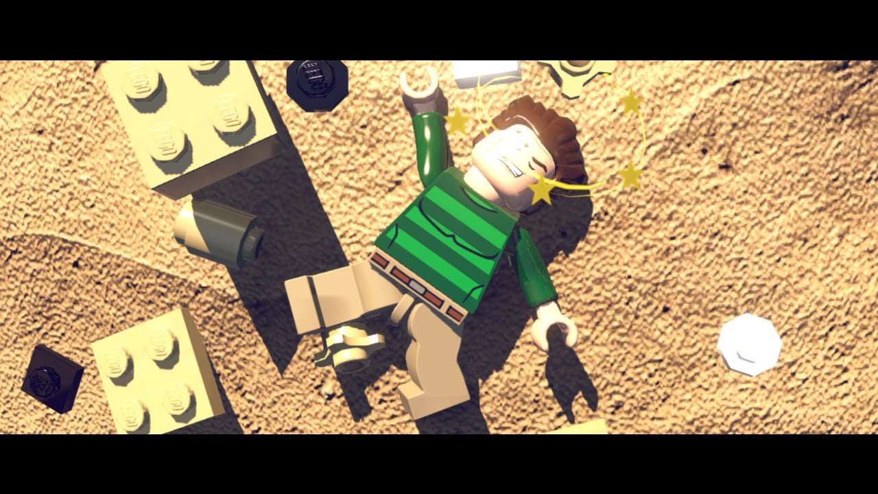
LEGO MARVEL Super Heroes GamePlay - [Hulk, Ironman, Spiderman vs Sandman, Abomination]
you see the shader in 11:50
Aight so
I've made a test and
void chooseInk (Input IN, SurfaceOutput o, inout fixed4 color) {
          float blend = (color.r > 0.5)*0.5;
          color = blend;
I wrote this to test
If the finalcolor thinger is only called once, then everything should be either black or gray
But
It's not
Areas with no lights on are black, areas lit by 1 light are gray, and areas with 2 lights are white
@errant ocean I think the technique used is quite easy. They have a material with a texture and normal map. Then the shader translate UVs over time. All the trick is to setup UV on the mesh so that a single direction UV translation yield to the desired sand movement.
So somehow it's calling it after every time a light is calculated and it blends the result together, possibly additively
Instead of once when every light has been calculated
I wonder if not using a lambert shader would solve things
Also interestingly, the earlier bug doesn't show up there
You've got me interested @woven loom, so I'm seeing if I can get this shader to work
@woven loom I think I got it
https://pastebin.com/maHiPt3v
Actually, that one only works with 1 directional light :/
But basically what I did was search for a vert frag shader that does Lambert lighting and with shadow support and edited that instead of trying to make a surface shader work
I used this shader as a base, but it's missing additional light support
https://joeyfladderak.com/let-there-be-shadow/
Shadows in Unity is something that in most cases is a given through the use of surface shaders, but sometimes you don't want to use a surface shader for whatever reason and create your own vertex/fragment shader. The biggest advantage is that everything is in your hands now, ...
Well...
I guess having to deal with not having multiple light sources all at once isn't too bad an option
I just wish I could apply the blending like
After all of the lambert passes are done
Okay I've got something I think
Nevermind...
Thanks @turbid elbow I tried just animationg the uvs and trying to get the sand moving but it looked really lame, I guess deformig the mesh is the important part
@woven loom I'm thinking the only way to get the effect you want with multiple lights support is to do a custom post processing pass
Or maybe I should try to figure out why finalcolor isn't actually final
... I just had an idea
I figured out how to make sure that the current pass is either a forwardbase or a forwardadd pass earlier
Maybe I could...
Hmm...
Nah nevermind it wouldn't work
The problem is that the additional lights are rendered afterwards on top of the base directional lighting, like a transparent object with additive blend. They are totally separate passes that don't know anything about the final color of the other.
The only way to get the final color of that object is by doing post processing after the object is fully rendered.
Hmm, trickier than I thought
Ah well
The method I'm with right now is still better than the one that had just no shadows
I'll just have to make ends meet with single light sources spread far apart for now
Or, alternatively, 1 directional light
Thank you for the help so far!
I haven't given up yet 👀
Hi all, how do I use shadergraph to fudge the motion vectors that are rendered? Basically, I want some things to have a different amount of motion blur on an individual basis. I get this may mess up TAA and other things but it might be OK if it's still in motion.
I see an "Additional Velocity Change" parameter in the Lit Master Node cog, but enabling it still does not seem to hint where I might control it.
Anyone have an idea why I can only access property block data in the vertex shader in the first instance of the draw call? in fragment i can always access the data no problem. heres the code https://hastebin.com/zaqasipumu.cs
if I do flat shading for triangles, I basically set all 3 vertex normals to the same normal, so that all texels have the same normal right?
but the lightning is still not uniform, since the texels have interpolated positions
how would I go if I want this really low poly water look where the lightning affects the full triangle in the same way
Anyone have a good trick to correct aspect ratios so that my rings aren't stretched on surfaces?
As far as I know you don't have much choice apart from world space texturing or scaling based on object scale
Sometimes batching can get in the way of all that though.
Hey folks. Still having trouble with my grass shader... Don't suppose anybody has any ideas? https://forum.unity.com/threads/why-is-my-grass-shader-shaking-not-billowing.747257/

Unity Forum
Hey folks. So, I'm working on the biggest shader I've written so far - a humble grass shader. But I need this shader to apply to a host of weird,...
@ocean mural here's something
Ah sweet, thanks @vocal narwhal ! I'll check it out
Hello, I was wondering if I could get a hand working out some wave shader stuff. I am new to Unity and seem to be a little stuck at the moment. I am trying to utilise parts from http://fire-face.com/personal/water/ and https://blogs.unity3d.com/2018/10/05/art-that-moves-creating-animated-materials-with-shader-graph/ but don't seem be having luck.
I have the Gerstner wave in with a custom node but am unsure how to use it for vertex offsetting. I was hoping it would resolve the clipping at the crest with my current setup.
The other confusing part is isolating the crests of the waves. I want to have light colours at the top but then also multiply a foam texture at the crest. Here is a pastebin of my graph. Any help would be greatly appreciated
Owen Deery

Unity Technologies Blog
In Unity 2018.2 we added the “Vertex Position” input to Shader Graph, allowing you to adjust and animate your meshes. In this blog post, I’ll demonstrate h...
Pastebin

@analog crown Which part? Or all of it?
@low lichen The peeling part. The deformation of the peeled part isn't an issue.
I'm not sure if this is done with shaders or geometry manipulation.
That looks like it's a completely procedurally generated mesh, because it becomes thicker the faster the tool moves
Likely created on the CPU side, because it also has physics afterwards
Right! How about the original mesh, are the vertices/tris being removed or displaced or is it just an alpha mask ?
Take a look at this game too : https://apps.apple.com/us/app/i-peel-good/id1471374791

App Store
How smooth are you?
WILD ADDICTING
Offline Mode
Oddly Satisfying
Zen!
Put your peel skills to the test! Relax and channel your inner chef in I Peel good. So many fun objects for you to rotate and carve? Can you score a perfect score? Fun and easy to pick up but don’t m...
For the original object, a mask revealing a different inside texture will suffice, unless you want deep grooves
Yeah, I tried a mask solution but it didn't look good. Thanks anyway.
Is there some way to set the keywords from the new ShaderGraph keyword properties? -- only via script? I'd hope for a custom material inspector
is anyone using Rider and got it to in some sense understand basic shader syntax?
I only get very very basic autocompletion based on words I already typed and syntax highlighting, nothing more
@gilded lichen Do ShaderGraph shaders not use the same keyword system as all other shaders? Shader.EnableKeyword or material.EnableKeyword?
Yes, via script that will probably work for the custom keywords one can now create. But the built-in Materials change options based on toggles that are part of their Material Inspector
Talking about those
And Shader Graph doesn't let you create custom material inspectors?
Not for the moment
Guys, who is using newer Unity versions - is the shadergraph property list scrolling works for you via mouse wheel? :D
I find this bug very annoying lol
it doesn't for me, it's awful lol
I still have the bug where the shader graph editor freezes that window if you rename three properties. Forces you to save and then reopen to keep working 😢
does visual studio have better support for shaders than rider?
There are some plugins for VS and VS Code that seems to have better support than Rider
is nobody gonna help me with GLSLPROGRAM?
ive been here like 1 week(s) finding answers here
@orchid harbor Do you mean you're trying to decompile precompiled shaders?
Has anyone ever experienced anything like this?
It's a terrain splatmap outline but I can't even comprehend how darkness converts to opacity 
reposting from #💻┃unity-talk
hey folks! we have a survey floating around where we want your feedback on graphics features. feel free to take a look! https://forms.gle/MpYJC6s8wkgcANSh6
Unity's Graphics team wants your feedback to help inform us as we set our priorities and plan our work for future releases. Unity graphics areas include: lighting, rendering (SRP, HDRP, Universal/LWRP, Hybrid Renderer), environment (terrain), shader graph, VFX graph, particles, post-processing, meshes, mesh API, graphics APIs, shaders, textures, materials, and frame debugger

Google Docs
Unity's Graphics team wants your feedback to help inform us as we set our priorities and plan our work for future releases.
Unity graphics areas include: lighting, rendering (SRP, HDRP, Universal/LWRP, Hybrid Renderer), environment (terrain), shader graph, VFX graph, particl...
any idea why ios/xcode would be complaining about this constantly? when it doesn't appear to be an issue in windows/editor Material doesn't have a texture property '_MainTex' Stacktrace is not supported on this platform. (Filename: Line: 1401) so far as i can tell none of my scripts are looking for a _MainTex in PropertyBlock or anything like that.
Are you using a scriptable render pipeline?
Are you using "material.color" anywhere in your code?
A lot of those "default setters" are broken on URP/HDRP since it's not called _MainTex anymore
i am using URP and just switched from LWRP, had to edit a few of the shaders to change the paths so far.
maybe i can get it to have a stacktrace or a filename to narrow it down somehow.
but that gives me a direction to start with, thanks!
Hey, so I am trying to make a shader where it applies an effect/color to everything inside the mesh that it is on, and makes the mesh otherwise invisible. I haven't been able to figure out what to even google for this. An effect sort of like this is what I am trying to achieve. An ideas?
@oak flare Chances are it's using one of the color channels for it's alpha instead of the alpha channel
Oh that was a day old
I'm still stuck on it, lol
How do I just neutralise it back to normal, I just want it's texture area, not it's texture or colours
@echo badger This should get you pretty far:
https://www.youtube.com/watch?v=OKoNp2RqE9A

Support me on Patreon ➜ https://www.patreon.com/DanMoran Follow me on the Twittersphere ➜ https://twitter.com/DanielJMoran Get the Assets for this Video here...
Basically, you want to apply a post processing effect in a specific area of the screen and you use the scene's depth buffer to figure out which pixels are inside a radius and should be changed
You can also do it without a post process step if you apply a custom shader on the objects that should be affected that handles the effect. That should have better performance because you won't have to do a depth pre-pass or any post processing, since you can get the world position within the object's shaders.
But that's less flexible, because it won't work with any object with any shader.
He actually says the opposite in the video, that making it per object would decrease performance, but that's under the assumption that you're doing it in a second pass, when you can do it all in the same pass.
I'm trying to implement shadows in an unlit shader, but SHADOW_ATTENUATION is always returning 1
So no shadowsshow up
@boreal heron Have you taken a look at this?
https://docs.unity3d.com/Manual/SL-VertexFragmentShaderExamples.html
Casting and receiving shadows is implemented further down the article
Yeah I'm using that as a reference, but it won't work
When I do "LightMode"="ForwardBase" the whole shader breaks
I'm on LWRP
Oh, LWRP uses a totally different lighting system
Oh, alright
It'll be more difficult to find examples of that since it hasn't been around for long
I have
This is what the LWRP/Lit shader looks like
https://gist.github.com/phi-lira/225cd7c5e8545be602dca4eb5ed111ba
You might be able to pick out the parts applying the shadows
Thanks
Looks like there are some keywords you need to add
?
Just Ctrl+F to find references to shadows and try to copy paste those parts into your shader
👍
No joy I'm afraid
@boreal heron Any errors?
No, it just doesn't recieve any shadows
Is it a shader you can't make with Shader Graph?
Yeah
It needs to get the main light direction, which there isn't a node for
and all the custom node solutions are broken
Is this broken already?
https://blogs.unity3d.com/2019/07/31/custom-lighting-in-shader-graph-expanding-your-graphs-in-2019/

Unity Technologies Blog
With the release of Unity Editor 2019.1, the Shader Graph package officially came out of preview! Now, in 2019.2, we’re bringing even more features and fun...
Ooh didn't see this one
oh!
ok I think I need to update my unity
I'm on 2019.1
well that's a shame I wasted time on that shader
why the fuck have they not fixed shader graph already?
Unity just straight up doesn't let me use subgraphs
K
Thanks
</rant>
Hey, thanks @low lichen that does seem like exactly the same idea as what I am looking for!
I have a couple questions, idk if you know but I may as well ask.
Most are related to converting it to Amplify. But one that isn't is, would this work on other render pipelines? I only want it for in editor only and not runtime. But not sure if this would work, do you know?
@echo badger If you make it an image effect, it'll work for any rendering pipeline
I believe Amplify lets you create image effects, right?
@low lichen it lets you do PostProcess shader, for an output it only has FragColor it seems. Would that be an image effect shader?
@echo badger Yes
@low lichen I am starting to understand this. And thank you for your help.
I keep looking but I don't understand how interpolatedRay does anything. It doesn't appear to be any different than ray. Is it different?
@echo badger Everything that goes from the vertex shader to the fragment shader is interpolated so each fragment/pixel gets a value that makes sense.
Because the vert function is only run for each vertex, while the fragment function is run for each fragment/pixel
Ooh, that is cool to know! So does that mean I don't need to worry about the vert stuff sense I am using Amplify?
I'm not sure
Alright
Anyone ever get UCB shader warnings for BUILT IN unity shaders?
[Unity] Shader 'UI/Unlit/Transparent': fallback shader 'UI/Default' not found
[Unity] WARNING: Shader Unsupported: 'UI/Unlit/Transparent' - Setting to default shader.
[Unity] Shader 'UI/Unlit/Text': fallback shader 'UI/Default Font' not found
[Unity] WARNING: Shader Unsupported: 'UI/Unlit/Text' - Setting to default shader.
absolutely driving me nuts. works locally fine.
can anyone help me, updated after my pc stopped working for months, from 2018.3 to latest, and now everything is pink
@low lichen Thank you so, so much for your help! I ended up just messing around with the script shader and ditching Amplify sense it isn't too involved of a shader and the effect I want is pretty simple. Converting was too much work.
Took a bit of figuring to get it to work in the scene view. But it works now! 😄
how can i expose these to inspector?
i guess it's not possible, but a workaround is to have a bunch of branches and expose some booleans. Then add a bunch of different master nodes
Okay so I have an issue with unwanted backface culling. I’ve tried everything but none of it seems to work, any ideas?
Is writing shaders for LWRP different from writing shaders normally?
@wary stump pink usually means material doesn't exist
yuck, well someone had some fun
I tried reconstructing the world position of the background in shader
works almost perfectly
I just need to figure out how to get the actual scene depth in metres, not in a weird view specific measurement
because currently when I look around the position shifts around a bit, mostly at the edges of the screen
Realizing this discord group is for asking questions but no one will give answers
@mortal surge What have you tried to fix your backface culling problem?
And this Discord server isn't just for support and anyone who tries to help is doing it on their own time.
@mortal surge you need a shader that is two sided, if you are using shadergraph it is this simple:
tick that box in the master node
if you are not using shader graph just write Cull Off in all the passes you have in the shader like so:
@cosmic prairie This video goes through getting a world position from depth
https://www.youtube.com/watch?v=OKoNp2RqE9A
Support me on Patreon ➜ https://www.patreon.com/DanMoran Follow me on the Twittersphere ➜ https://twitter.com/DanielJMoran Get the Assets for this Video here...
@low lichen I know it’s not just for asking help, but I meant that I’ve been in a lot of Discord servers where people just keep asking questions so no one can get answers. I’m NOW realizing it’s the opposite here, sorry and thanks
@cosmic prairie I’m not using shadergraph, so I’ve heard you could write Cull Off in your shader but haven’t seen where exactly to write it.
You can put it right underneath the Tags line:
Shader "Unlit/NewUnlitShader"
{
    Properties
    {
        _MainTex ("Texture", 2D) = "white" {}
    }
    SubShader
    {
        Tags { "RenderType"="Opaque" }
        Cull Off // <--- Goes here
I’m really new to Unity so do I have to create a new shader or go to edit shader tab at the material I want to disable culling on?
What shader are you using for the hair?
A standard shader
You can't edit the standard shader directly, because it's built-in to Unity. But you can duplicate it in your own shader and edit it

Gist
Standard Shader - 2 Sided (cull off). GitHub Gist: instantly share code, notes, and snippets.
This is a duplicate of the standard shader, but with Cull Off
So you create a new shader, paste this in there and change your material to use this shader instead
You're using transparency I guess?
Yes
Okay the name of the document was wrong, I changed it and it kind of works now
Thanks @low lichen it works now
Hi 🙂 I'm learning shaders (in shader graph). I want to understand the screen position node and understand why this combination of nodes gives the gradients near egdes. Can someone explain please it to me? In Unity/C# knowledge I would position myself in a range between mid and high.
I'm talking about those intersection gradient edges:
So all opaque things render into the depth buffer. It's basically a Z coordinate for all your pixels.
When you render an object, the fragment shader already knows where it's going - that's your "Screen Position" Node. It has xy (for the 2D xy coordinate on your screen) and w for the "depth" of the pixel. That's the value that would go into the Depth Buffer. So if you compare what's in the depth buffer (Depth Buffer node) with what would go into the depth buffer (e.g. you subtract the two, as in your example) you get a "gradient" for how close the thing you want to draw is to what is already there. Note that it's per pixel, it really doesn't see "edges" or "planes" or whatever.
You'll get a better understanding of that if you apply that same shader to a Quad that's parallel to the wall and then turn the camera.
@gilded lichen thank you, I think I got this now 😉
Is there a bug with shader graph where if you make a node on the blackboard it freezes and you have to save and exit then reopen shader graph to continue using it or just me..?
Happens for me in 2019.3 I have to close the shadergraph window and relaunch it.
yea same, ok then its a bug
And how is that going?
Add a multiply node and connect the fresnel and the color you want
I tried add thought it would add the color and fresnel but ok thanks
The reason why add doesn't work is because it would be trying to add (1, 1, 1) with your color, which will just give you numbers higher than 1, which is just a brighter white
It's a start
epic
Now I'ma try some other shader
maybe sort of hologram
I don't have the right texture and can't find one
so I'll try without texture
https://www.youtube.com/watch?v=TYb6LIt6ib4&t=10s
in the intro to this vid, where the balls impact the shield, how does one calculate the point of impact and does it have to be coded separately or can it be achieved within shader graph

A quick overview of the ForceField Effects Unity VFX Asset Check the full Asset here: http://u3d.as/1frw
@wraith gull The point of impact will all be done in C#. Very likely its just a sphere collider with the OnTriggerEnter method. This will then pass that point into the shader/shader graph for it to do stuff with
hi everyone, I have a question. I'm learning shader graphs and I want to change a color of a simple cube but I actually can't figure out how to do so in LWRP. I've created a new shader graph, also new material and linked a material to my shader graph. Shader graph looks like this, but the object in the scene does not reflect the color shown here. Actually the color doesn't even change. I didn't make any changes to the project - just load up the LWRP and created this shader
This is cube, that should be red. (material is applied)
any help really appriciated
@distant nimbus Did you save the shader graph? The Save Asset button, top left.
I want more cascades
Hello there, i have a question, is there a wany to make a shader that renders like in a submarine and goes underwater and the player still walk jump ect like if it were on land even it is under water
Like in this example
@rain scaffold The submarine itself would just be a 3D model that the player is inside of. You'd probably be able to just use Unity's CharacterController and place it inside the submarine. Then you'd move the submarine anywhere you want it to go
As for the water effect, it would likely be 2 parts: the surface waves and the underwater part
So I'd start with just making both separately and then blend them together in some way
@low lichen but i want to go out and inside the submarine, also the water is the Community ocean one
You may need volumetric water. Depends. You might be able to fake it on the windows, then use 'normal' water that allows submersion. But otherwise you need volumetrics.
Crest could do this, https://github.com/crest-ocean/crest

GitHub
An advanced ocean system implemented in Unity3D. Contribute to crest-ocean/crest development by creating an account on GitHub.
FIIIIINALLLYYY I DIIIIIIID IT
World space reconstruction from scene depth
and it's per-object , not a screen space effect!
this-is the graph for it:
makes no sense but works flawlessly
should I release this as a free asset? anyone needs this kinda stuff? I mean the subgraph
btw @low lichen that video proved to be mostly useless for my usecase (but thanks anyways! 😄 ) since it is a screen space effect and it also uses an extra script to make it function properly
@cosmic prairie for what is this used?
Could be used for decals
@meager pelican can so the dissolve shader give that effect?
@rain scaffold decals, magic effects, fake lights, even anti-lights!:
next thing is going to be reconstructing the normal, should be easy now, just have to get 2 more points around the pixel and do a cross function
quick question, I know about 9-slicing and using sprites but would a 3D selection box be possible with shader graph like this? Using this setup the lines stretch to be wider on the siders as you drag for example a 1:8 ratio (rectangle). What I'm looking for is to have the lines always drawn at the edges basically and the middle filled with transparancy.
@drifting edge Do you mean you want the edges to be of uniform width? If so, it would be better to not use a texture at all, but instead generate the lines in the shader
alright will try that
alright, that saves me a texture, but the result is the same unfortunately
You'll have to take the object's scale into account somehow
@drifting edge This works. I highlighted in red where you put the line width for X and Y.
Didn't know Rectangle existed, that makes this a lot simpler.
amazing! thanks, we both learn something haha
:P if something doesn't make sense, I can explain it for you
it's definitely much better, but I'm having some backface problems maybe and a bit of stretching
But your example should give me enough to work with, I'll keep you updated
Oh, I didn't think to try it on a cube, but I guess that was the original question
Is there a way to randomize shader noise during runtime? As I'd like to make a TV static-like effect
@upbeat topaz In Shader Graph or shader code?
Yes, with the Random Range node
You just need to give it a Vector2 as a seed to get TV static-like noise
The UV node is fine
oh, it works now, thank you
And add the Time node in there somewhere to animate it
yea, multiplied the uv by it
I did this, but i'm not sure it makes sense
Another node I didn't know existed. That's probably a better fit
Sorry, I don't use Shader Graph much :P
Setting both of those values to 10 is awesome by the way!
looks like gasoline on water
both methods have pretty cool results, so thank you both
@drifting edge For the cube, you need to take into account the Z scale too. I just made it work for quads so I only used X and Y
That's how you fix the stretching at least
yes that make sense now that you mention it
But I don't know exactly how to incorporate Z into it
my way of learning is brute forcing it until it works, then reverse engineer it haha
thats why shader graph is so amazing, you can mess around so easily
@drifting edge Thinking about it, you probably need to get the normal and use that to determine which 2 axis to use. Because ultimately you have to use 2 axis when working with a 2D texture, like the rectangle.
@drifting edge you can set up a 9 slice type system in the shader
as long as you are ok with the center parts stretch as much as they need to, you can get the scale of the asset and change the way the UVs work
Here is the graph to solve for Z on a cube
A quick video of it with scaling on the Z (didn't set it up on other axes).
quick question: is there an unlerp or inverse lerp function for compute shaders? Can't seem to find it
I imagine you just have to math it out on your own
ah ok. i can totally do that. just wanted to avoid doing that in compute shaders for the rest of my life if i didn't need to lol
i imagine you can, but I'm new to compute shaders so I haven't gotten that far yet
yeah, they are hard enough as it is
got some sweet-ass raytracing going tho! big fan of the potential of compute shaders for helping me do cool stuff
nice, and kind of creepy
I made a photoshop type editor thing in unity using compute shaders, layers and blends, even real time height to normal, etc
so fast
yea I was thinking about taking a stab at some sort of texture generation/processing system using compute shaders. seems like a good way to learn while also making a fun tool for yourself
totally, I wanted to make a 'material' helper especially for people to start to understand PBR, etc
whoah you went all out with the tool!
yeah, I am sad I didn't take it further
probably won't work anymore in the new unity's 🙂
ah that's too bad
lots of abandoned experiments
with your ray tracing thing, how does it differ than the ones rolling out in unity and unreal ,etc?
@rustic dragon everything is defined in code so there's nothing in my unity scene except a camera that I blit my render onto. so I couldn't throw a bunny in there right now as all the objects (the plane and the sphere) are just defined by intersection functions
Also Unity's raytracing won't be fully raytraced rendering. It'll just use raytracing to get higher grade effects like better SSR and GI
from what I understand ^
I assume you can't use RTX though, like Unity's implementation
Yea I'm not using any fancy RTX acceleration stuff. Just a plain old compute shader
My implementation is pretty terrible because every pixel shoots a ray that checks against every object for every bounce. it gets exponentially slow the more objects i add
@tardy spire ah cool with the raytracing, I imagine it is a bear to keep optimized
Yea. It's definitely not gonna be something I'm gonna worry about tho haha. I just wanna get my toes wet
Hey. Anyone any idea why a camera with a transparent clear colour does not send that that transparency to a post processing shader on windows? (on mac it works fine)
Turning HDR off fixes this 😅
heya guys
been working on a low poly water shader
and ran into a pretty significant issue
the normals are all still the default up
im just using the World position and ddx/ddy to get the Surface normals:
this method worked fine on my friends HDRP project
but my LWRP doesnt seem to be getting the right position
im using noise to offset the verticies in the Y axis:
but that doesnt seem to translate to a change in the world position
looks fine on the normalize subgraph, maybe skip the tangent graph?
oh and the to tangent graph is in position mode not rotation
skipping the tangent transform messes up the lighting because the Normal Information is expected in tangent space
this is the World position mapped to the Emission color
it shows that it doesnt take the new vertex information into account
in this case it doesnt matter:
but for sanities sake i changed it to direction. no change
and did you try skipping it?
i forgot it and the lighting was really wierd because it would only light up when the light direction was paralell with the horizon
weird
is the master node right after the transform?
well I'll have to try this after I get back home
yes it is
the issue is that the Position(world) node returns the original position opposed to the new vertex position after the vertex shader
Hi. If you use 2019.3 and version 7.1.1 or higher then that issue is solved, and you can feed custom normal and tangent calculations to vertex c: @gleaming fog
Hello ! Anyone knows something about Correcting affine texture mapping for trapezoids without distortion ?
Subject here :
Unity Forum
http://stackoverflow.com/questions/12414708/correct-glsl-affine-texture-mapping
I needed a stable place to post this package, and I figured this might...
i think this should solve it : http://web.archive.org/web/20080209130648/http://www.r3.nu/~cass/qcoord/
Is the width parameter the distance between the upper vertices ?
like :
@stone sandal thanks for the awnser. Unfortunately I can only use 2018.8. 8f1 due to this being a school project
is this just a shadergraph thing or are manuallly written shaders effected by this? becus then you can just compile it and correct it, or maybe write a vertex shader
here is an image of the problem :
Alright, hello again haha
To correct the texture mapping of a trapezoid, I used the solution found here :
One user wrote this shadder which is working :
Unity Forum
http://stackoverflow.com/questions/12414708/correct-glsl-affine-texture-mapping
I needed a stable place to post this package, and I figured this might...
Deal is, It doesn't allow for texture tiling, despite showing it on the material helper :
I need tiling...
Any of you, magic wizards of shadders, could guide me to a solution ?
Solved, thanks.
@low lichen @rustic dragon looks great! thanks a lot
Bend object from middle shader graph unity?
I got strange result while doing the same.
that is a confusing image 🙂
And a confusing phrase
this isnt google lol
Hi all, I'm trying to populate a couple of RenderTextures in a compute shader as RWTexture3D<> which I then use in an image effect shader as a way to speed up raymarching.
The issue I'm having is that I can't tell if the textures actually contain any data at all. I suspect they're just full of 0s although I can't tell as I can't find a way to dump out the data to a text file to check. Is it possible to write to a RWTexture3D in unity? It seems like a few others have had similar problems but I can't find any solutions
You could view a 3D texture by checking one slice at a time
I suppose an alternative is to use a 1D RWStructuredBuffer array, assuming I can get that out of the compute shader!
I haven't heard anyone having issues with writing to 3D textures and I can find examples of compute shaders doing just that
@real pilot it works I recommend installing renderdoc.org u can easily capture inside unity and look at the data
Unity will detect it and add a capture button
Add #pragma enable_d3d11_debug_symbols to your shader and it will also recognize the struct/property names
Greetings!
I'm trying to get a distortion effect on a model (some sort of ghostly effect). I've found this tutorial by Unity (https://www.youtube.com/watch?v=atPTr29vXUk).
However, the distortion effect is applied through a "lens" of some sort (in this case the globe).
I thought about layering 2 cameras and having one only render my ghosts, but I've found that layering cameras is not possible in LWRP.
Is there a way I could apply this effect on a model without having it be through this "lens" and distort the background?
I'm not an expert but I think you might be able to bring this object to a seperate layer, add a custom forward renderer, and add a specific render feature for the layer of that object.
If you want a better explaination let me know
Ultimately to do this effect, you need to have a screen sized render texture of just your ghosts rendered onto it, then overlay that texture with distortion in a post processing step
You can use a custom render feature to get that texture, like @drifting edge suggested
https://youtu.be/szsWx9IQVDI @left basin I think this is relevant
Let's learn how to render characters behind other objects using Scriptable Render Passes! This video is sponsored by Unity ● Download Project: https://ole.un...
Thank you very much for the quick response. My knowledge of shaders is pretty limited, so I don't really get what you're telling me, but I'll go watch that video and see if I can figure it out! 😄
Does anybody know, is it by design, that overriding built-in shaders by name doesn't work in unity2019, or I'm doing it wrong?
i'm adding additional render-type tag there, leaving all the code almost the same
And now I see 2 shaders of same name:
I think the problem with what I am trying to do is that my current shader is added to an object that distort what is seen through rather than distorted itself.
Is it possible to achieve the same type of effect by applying a shader directly to the object I want to distort?
It's basically a semi-transparent wobbly version of my model superimposed on another wobbly semi-transparent version of my model.
@left basin You can only draw pixels in the space the object occupies, so you can't draw anything outside of the object.
I only see this being possible with an image effect/post processing
That's unfortunate 😦 If they do allow multiple camera to stack, I could cheat the effect easily, hopefully that feature will get added soon
Anyone knows a cool source to study how to make animated low poly water using shader graph?
Just played around with Shader Graph and figured out how to get a basic terrain shader made! (You have to turn off Instancing unfortunately though). But here's the graph if anyone wants to get terrain shaders started to make them unique 🙂 (I didn't include Normal Maps as it works the same way, so to make the graph smaller I just stuck with Albedo).
Oops in the Samplers change from object back to Tangent - just realized after hooking up normals changing it to object got rid of shading lol.. (Turned it off because of the instancing giving warnings about tangents). But changing them back to Tangents worked beautifully.
how do the UV's work for this as a layer blend?
What do you mean? It's essentially a splatmap shader. It however I'm sure only works for 4 textures as I'm not sure if we have access to doing multi-pass shaders. (could be wrong on that part though), still kinda new to Shader Graph.
Is there a way to reuse compute shader code? Like if I wanted to create a compute shader that just holds a bunch of utility functions could I use them from another compute shader? I've been on the struggle bus finding info on compute shaders within the context of Unity, so apologies if this question has been answered before
@tardy spire I haven't tried using my own files but I know you can include cginc files. one of my compute shaders has #include "UnityCG.cginc"
I'll give that a shot, thanks!
@grand jolt you have the lerps being driven by the UVW channels of the UV's, unsure how that works
I figured it'd be vert coloring
I think my compute shader issues arise from my lack of understanding of how to get the (int) pixel coordinates within the shader itself. I've been googling for a while but haven't found anything relating to RWTexture3D. Would anyone mind pointing me to some useful resources to learn about this, please?
@left basin You could put a copy of your object over your object slightly bigger in size with a transparent shader on which does the warping effect. There's a glass example in the forums for lwrp/urp. Best I can think of outside of an actual screen effect
I'm actually working on a cartoon water shader...
is there a way to reset shader-material properties to defaults when switching shader on material without recreating the latter? I want to have an option to tweak some properties from inspector but at the same time when switching the shader on material I want them to reset to new shader default values.
maybe boolean would help
is there something like the unity docs for the hlsl/glsl shaders in unity? Not sure which one unity uses.
@pine lily I refer to http://developer.download.nvidia.com/cg/index_stdlib.html
Cg Standard Library Documentation
thx
do you have a good source to learn how shaders are coded/work. I kinda already have what I need: https://gamedev.stackexchange.com/questions/135375/animated-textures-for-models-how-to-write-a-shader but I want to adapt it so I can have the albedo and normal scroll in different directions.

Game Development Stack Exchange
Was watching some Rocket League and notice there was animated decals and wheels.
.
I would like to implement something similar to the effects in the image above.
How would I go about writing a...
OMG I am such a nub... I did loads of shader coding yesterday wondering why nothing was working. I sleep on it, come back fresh, and instantly notice that I managed to duplicate the shader and was using the wrong version! Happy days ahead now I realise I can actually do what I thought I couldn't! ;D
how did u learn the shader coding?
@pine lily same as learning usual coding, reading manuals, posts, trying to do small demos and so on
Can image effects be applied to only certain objects / layer? Or can they only be applied to the entire screen?
All that an image effect does is it renders a quad in front of the camera that takes up the entire screen and it draws something with a shader
Usually that shader will have access to a texture of the last rendered frame, so it can use that to draw a modified version of the last frame
So understanding that, it doesn't make sense how this quad in front of the camera can somehow only affect certain objects or layers
But what you can do is give this image effect shader a texture that only contains certain objects or layers
How you get this texture is up to you. You could setup a separate camera that renders only the layers you care about and draws it to a render texture and give your image effect that shader
With LWRP, you can make use of custom render features
I thought about the second camera, but it's not supported in LWRP. I'll loop up custom render features. 🙂 ty
I'm pretty sure you can have multiple cameras, just not all drawing to the backbuffer or something like that
Maybe that's wrong, but I'm pretty sure I've gotten that working in LWRP before
Hi all.
I can't find out how to get the correct IDs for the coordinates of my RWTexture3D.
I can get it to work naively for small textures like this:
[numthreads(1,1,1)]
void CSMain (uint3 id : SV_DispatchThreadID)
{
    float3 checkPosition = float3((id.x + 0.5) * voxelSize, (id.z + 0.5) * voxelSize, (id.z + 0.5) * voxelSize);
    //...code to calculate output value here...


    Result[id.xyz] = output;
}
and at the Dispatch stage calling for my width, height, depth number of threadGroups, but I know this is not the right way to go about it, I just can't work out what the right way IS!
Before my checkPosition line, I'll need some way of mapping whatever this thread ID is to the integer index of my texture3D position. Does anyone have a link or the time to help me understand how to do this? I didn't find the info on the unity docs or from googling.
Hi.
I have an issue related to Depth mask.
The mask works pretty good all other devices but Google Pixel.
In place of mask there is a gray color.
Here is the shader coed I used for mask.
Shader "Masked/Mask" {

    SubShader{
        // Render the mask after regular geometry, but before masked geometry and
        // transparent things.

        Tags {"Queue" = "Geometry+10" }

        // Don't draw in the RGBA channels; just the depth buffer

        ColorMask 0
        ZWrite On

        // Do nothing specific in the pass:

        Pass {}
    }
}
Does anyone face with similar issue?
@left basin If your second camera is rendering to a render texture, that works fine in LWRP
@real pilot You mean converting the 3D pixel position to a single index int?
I mean getting the uint3 pixel coordinates (from 0 -> width, 0-> height, 0-> volumeDepth pixels)
That is what id is, unless I'm misunderstanding what you mean
id.xyz are your pixel coordinates
so far I'm using the SV_DispatchThreadID directly, but that seems to require me using 1,1,1 and putting in 1 threadGroup per pixel during dispatch
Try setting numthreads to 8, 8, 8 and when dispatching, set the numthreads to width/8, height/8, depth/8
k will give that a shot, thanks
@sour jackal What is this for? Just a shader to write only to depth?
@low lichen It is used as a mask on a 3D object.
To make the pixels of the 3D object behind the mask not draw?
@low lichen so just to make sure I understand this, the unit3 id : SV_DispatchThreadID id value is the pixel coordinate, and to increase the possible size of the texture, I just need to increase the numthreads and scale the threadgroups by 1/ the same factor, yes?
No need to change the numthreads in the compute shader
They can remain the same regardless of the resolution of the texture you're working on. Just make sure to give it the right dimensions/8 in Dispatch
okay, cool thanks
Only some people actually understand the theory behind numthreads and what numbers make sense for what. And I'm not one of them
I've stuck with 8,8,8 or 8,8,1 for 2D, because that's what I've seen others do.
whao okay it didn't like a 1000 ^ 3 texture
@low lichen
To make the pixels of the 3D object behind the mask not draw?
Yes.
Is it working on other Android devices other than Google Pixel, or have you not tried others?
@low lichen Yes. It works on other devices like Google Nexus 6P, Huawei p20 light, IPhone SE, IPad mini
Then it's some specific hardware differences likely. It's a very simple shader you have, so I can't imagine what you could change to make it more compatible.
@low lichen , I'm not sure I understand how I can achieve stacking 2 cameras. Since I switched the project to LWRP, I do not have the option of "Clear Flags > Depth Only".
So my camera that renders my ghost has a background and it is over everything on the screen so I don't see what the other camera renders.
@sour jackal All I can recommend is doing the shader differently. You can include vert & frag in the Pass and write only to depth that way. You just use SV_Depth instead of SV_Target in the frag to only write to depth:
float frag(v2f i) : SV_Depth
{
    return 0; // Return actual clip space depth here
}
@low lichen Thanks. I will try now.
@left basin You don't want to stack them. You want the second camera to have a target texture the size of the screen and render your ghost objects on to that
Then you can use that target render texture in an image effect and overlay it on top of the screen
The actual image effect would be pretty simple. It takes the ghost screen texture, distorts it and blends that on top of the screen.
@left basin Do you only have one ghost or always the same ghosts in the scene?
1-5 ghosts
If you can get a reference to their renderers in a custom script, you could do this even without a second camera
Hey everyone. Is there a shader reference I need to use to get the screen as it is displayed in the game view? I'm currently using _CameraOpaqueTexture but it seems to omit any world-space sprites or canvas image elements - using LWRP.
@surreal widget _CameraOpaqueTexture will only include opaque objects, as the name implies
Your sprites are probably transparent
Yeah, I figured that was the case.
I take it Unity hasn't implemented the ability to grab the whole screen in shader graph yet?
It's a limitation of LWRP rather than Shader Graph
Ahh, well I'll need to figure out a work around, thanks!
@low lichen
Tried this way. But this doesn't behave like Mask.
    SubShader{
        // Render the mask after regular geometry, but before masked geometry and
        // transparent things.

        Tags {"Queue" = "Geometry+10" }

        // Don't draw in the RGBA channels; just the depth buffer

        ColorMask 0
        ZWrite On

        // Do nothing specific in the pass:

        Pass {

CGPROGRAM

            #pragma vertex vert
            #pragma fragment frag


            struct appdata
            {
                float4 vertex : POSITION;
                float2 uv : TEXCOORD0;
            };

            struct v2f
            {
                float2 uv : TEXCOORD0;
                float4 vertex : SV_POSITION;
            };

            v2f vert (appdata v)
            {
                v2f o;
                o.vertex = v.vertex;

                return o;
            }

            float frag (v2f i) : SV_Depth
            {
                return 0;
            }
ENDCG
        }
    }
}```@sour jackal Does your original mask also mask out the skybox behind it?
@sour jackal Returning 0 will set the depth to be at the far plane of the camera. It should look like this:
CGPROGRAM

#pragma vertex vert
#pragma fragment frag

#include "UnityCG.cginc"

struct appdata
{
    float4 vertex : POSITION;
};

struct v2f
{
    float4 vertex : SV_POSITION;
};

v2f vert(appdata v)
{
    v2f o;
    o.vertex = UnityObjectToClipPos(v.vertex);
    return o;
}

float frag(v2f i) : SV_Depth
{
    return i.vertex.z;
}

ENDCG
When you say I could simply grab the renderer and do the effect there, any chance you have a source that could explain that process @low lichen ?
I'm looking into it myself. Unfortunately, LWRP/Universal doesn't let you add command buffers to cameras, you have to use custom renderers. Still possible. I'm creating a prototype right now.
@low lichen No, the skybox is visible through Mask.
Also the shader you had sent, didn't mask at all.
@sour jackal It doesn't do anything? It's invisible?
For me it masks out everything, including the skybox
Yes.
Yes it's invisible?
Are you trying on pC or on a mobile device?
Just in the Windows Editor
@left basin Is this the effect you were going for?
https://gfycat.com/EasyIncompatibleAtlasmoth

Yes, this is similar to what I was going for.
Here is a gif of the effect I'm trying to duplicate https://cdn.discordapp.com/attachments/497874081329184799/626099885598310420/Distort.gif

Hey, that's the new unity tutorial!
No, you wouldn't be able to get such a displacement with vertex displacements
What I do is I let the scene render normally first. Then after everything has rendered, I set the target texture to a render texture I make and manually render the ghosts into it
Amazing
so I end up with a texture that looks like this:
Then I blend this texture on top of the already rendered scene
But distorting it before I do
Does it work even if you put an object partly in front of the monkey?
Yes, because I use the same depth buffer as the camera's actual texture
So the ghost texture ends up looking like this
Wow, would you mind sharing me the project so that I can learn how you did it? That's huge
I made this in the 2019.3 beta, so I'm using Universal. But all the features should also be in the latest LWRP
Is there a way to make a function in a compute shader private so that other compute shaders that include the file cannot use it?
@tardy spire all that #include does is it literally takes everything in the include file and pastes it into where the #include is. So private functions doesn't make sense.
@left basin Yea, I'll send you the project
❤
Shaders and Renderers are still black magic to me, it's crazy the things you can achieve with them
@low lichen gotcha. thanks
yeah, I wanna use it to program boids
@left basin Here it is. I didn't bother putting any comments, so it's probably not very clear. Just ask me if you have any questions about how it works.
Much appreciated
If you want it to work on LWRP, you'll have to change some of the scripts referencing Universal to reference LWRP instead
I changed Universal to LWRP and don't have any errors in console anymore, however, the ghost is not moving
Oh sweet, got it
There was something that got unhooked in the Forward Renderer
Nice. The GhostImageEffect material controls the distortion if you want to tweak that
You could also probably recreate that particular shader in Shader Graph if you want to customize it further
I think I did something wrong though, the ghost effect is not placed where the ghost is and is not getting culled by the box
I'm installing 2019.3 to see what it's supposed to look like so I can compare
I'm trying to port it back to 2019.21f1
Works for me
What was the thing that got unhooked in the Forward Renderer?
This is what CustomForwardRendererData looks like, I assume I need to hook the Ghost Effect in RendererFeatures?
Yes
This is what it looks like after I rehook it
Hmm
Can you screenshot the properties of GhostImageEffect material?
@left basin Should look like this:
I trying reimporting and I am getting a "Missing . FinalBlitPass render pass wil not execute. Check for missing reference in renderer resources." error spam
(My GhostImageEffect material looks the same as yours)
There's a reference kinda hidden away that might be missing. In the project view, the CustomForwardRendererData should be expandable and show the GhostEffectRenderer there
If you select that, there will be a material property that should be set to the GhostImageEffect
And it's working
woo
I reimported and it's working fine, I must've missclicked somewhere the first time
Nice!
Yeah, though it will do that no matter the distance between the cube and the ghost
So your camera is reading what it sees, and the part where it sees the monkey is drawn onto a flat surface. And then the GhostImageEffect is applies a shader to that material to distort the image on that surface and then you redraw it onto the output?
Almost. You'll notice that the ghosts have a script on them. That script lets the custom ghost effect know of all the ghosts that should have this effect
The custom renderer will wait until the camera has finished rendering everything. Then it will render only the ghosts again to a render texture, instead of to the screen like the camera does.
Then this texture is overlayed on top of the screen with distortion applied to it
That's pretty awesome
I found out what the cause of the off-set was from earlier, I didn't import the project settings from the project you linked
When I import them, the monkey isn't offset anymore
However, when I import the project settings, some of my other shaders stop working
They become fully opaque for some reason
Not sure what that could be caused by
Oh, it might be the SRP Batcher
I disabled it for my project
Not because it was causing problems though
Just compare the render pipeline assets
@tardy spire you can #ifdef the function then have a #define in the compute shader that wants to use it, so the ifdef block gets compiled in
@uncut karma What if the shader that wants to use it is the shader that is getting included in other shaders that shouldn't use it? Won't the define get copied too?
I was assuming the define is in the shader or compute file, but this really isntneeded since any codenot used by a shader is completely compiled out
the "Depth Texture" was checked, which made the cube not cull the monkey, so that's fixed. The only thing left to fix is the money ghost effect is off-set instead of being overlayed on top of the original one
It's useful for changing behavior with system features variants etc
If I change the magnitude in the GhostImageEffect material, it moves the monkey away or closer. I assume you re-offset it somewhere after so that it gets overlayed?>
No, magnitude wasn't causing that effect for me
Perhaps someone can help me with this. I'm following the official Unity tutorial on Vertex displacement in Shader Graph. But when I press Save Asset and go to view it in the scene the Mesh moves to 0,0,0 world space position and can only see it if my camera is directly level with it and have no more than roughly 5 degrees angle above or below it or it disappears again.
Here's the graph
Oh and also - not sure if it's related but the Time node isn't doing anything
Got mesh to show where it needs, apparently the world space stuff is wrong, just set all the wordl stuff to Object and it worked... But Time still dont work
you are blowing up your visual model, where your collision bounds are super small, so when you zoom out to see the model, I think the models just culling
like when you select your model and F to it, do you see the collision bounds?
Naw I see the mesh fine now, I just had to change it all to Object space rather than world space, I see the displacement it's very light like I wanted.... But now the Time node isn't functioning correctly... If I press Play I do in fact see the time node scrolling the Simple Noise node, but it's not reflected in game
0.5
Shader error in 'Shader Graphs/Selection': redefinition of 'unity_Builtins2Array' at /Users/wybre/Unity/DiggingGame/Library/PackageCache/com.unity.render-pipelines.universal@7.1.2/ShaderLibrary/UnityInput.hlsl(114) (on d3d11)

Compiling Vertex program with UNITY_PASS_SHADOWCASTER INSTANCING_ON
Platform defines: UNITY_ENABLE_REFLECTION_BUFFERS UNITY_USE_DITHER_MASK_FOR_ALPHABLENDED_SHADOWS UNITY_PBS_USE_BRDF1 UNITY_SPECCUBE_BOX_PROJECTION UNITY_SPECCUBE_BLENDING UNITY_ENABLE_DETAIL_NORMALMAP SHADER_API_DESKTOP UNITY_LIGHT_PROBE_PROXY_VOLUME UNITY_LIGHTMAP_RGBM_ENCODING
2019.3.0b4
any ideas?
URP 7.1.2
An error like that from Shader Graph is likely a bug and not your fault
Ahhh now I see why the time node wasn't working. I didn't have Animated Materials Ticked 🙂
@drifting edge I think I saw that as well, definitely not an issue on your end
I think the older 7.1.1 should work
anyone know how i could go about a freezeframe effect via shader? I'd like to be able to capture the current camera frame somehow and modify it
@shrewd mirage there arent like states on shaders, but there are many ways you can get a hold of the camera data itself on unity. You can render cameras to runtime render textures and use that data as a source on your shader for example
I was trying to do this purely through a shader for VRChat since scripting isn't allowed there
There at least used to be captureframe on the api as well but I dunno if it is still a thing
also using this to learn shaders better
I dont think you can do that purely on a shader as you have to have the data stored somewhere
But then again, that is just my impression on this matter, I'm not hardcore shader guy :)
Also curious how you'd trigger that feat without scripting? Like are there some existing events you can hook that into?
i can still use an animation to change shader/material properties
i would just need the animation to be the master controller basically
so it would probably require a few tricks/hacks
You can still add events to animations too to run scripts if it is like stock unity anim
but I have a feeling this is some super specific use case now
Oh ok
No ideas then :D
I mean regular shaders are basically just math operations done again for each frame, if you need to store some data in or out, that has to exist on some memory which isnt allocated by the shader itself, it is usually given to the shader as a resource
@low lichen
Here how it looks like on Google Pixel.
It should be transparent instead.
@sour jackal Would it be enough to just use an unlit shader with the same color as the skybox?
@low lichen No. I don.t think so.
@sour jackal This shader works as a mask for me. Are you sure it doesn't work for you?
Shader "Masked/Mask" {

    SubShader{
        // Render the mask after regular geometry, but before masked geometry and
        // transparent things.

        Tags {"Queue" = "Geometry+10" }

        // Don't draw in the RGBA channels; just the depth buffer

        ColorMask 0
        ZWrite On

        Pass
        {
            CGPROGRAM

            #pragma vertex vert
            #pragma fragment frag

            #include "UnityCG.cginc"

            struct appdata
            {
                float4 vertex : POSITION;
            };

            struct v2f
            {
                float4 vertex : SV_POSITION;
            };

            v2f vert(appdata v)
            {
                v2f o;
                o.vertex = UnityObjectToClipPos(v.vertex);
                return o;
            }

            float frag(v2f i) : SV_Depth
            {
                return i.vertex.z;
            }

            ENDCG
        }
    }
}
@low lichen This works as mask on my side as well.
I think I missed o.vertex = UnityObjectToClipPos(v.vertex); this part yesterday when checking. That would be the reason.
Later I will try this version on Google Pixel as well. Thanks
With this setup, you would also be able to do textured masks while still just using quads or whatever mesh
@low lichen Hi. Thanks. This worked.
@sour jackal Awesome!
is there any tool to debug shaders
will that tell you the general cost of a shader, especially the ones with the new pipeline and the ones you create with the shader editor?
@rustic dragon I would not want to try and quantify that by a single tool looking at a random frame, since many things can affect. But I believe it's possible, I'm not experienced user of renderdoc I just know of it's existence.
I was doing some comparisons recently on a shader I made, primarily to check it was instancing properly etc. For this I just used the unity editor and spawned 100 objects using my shader and did same test with unity built in which was next closest match to my shader.
gauge performance with unity's built in profiling tools, I'd imagine similar for testing shadergraph is a sensible approach. But you would also need to compare on target platform.
yeah, thinking of something like in unreal where it tells you the instructions count, samplers used, etc in an output window, then it has the shader complexity visualizer in the editor
shader graph doesn't currently have support out of the box like the instruction count, etc. from unreal, but it's a high priority feature we're looking into
@stone sandal great to hear
Does anybody know if Shader Graph does any support for font materials in the ui?
I followed AE Tut's Water fountain using shader graph editor and for some reason everything is now pink purple and errors:
Anyone knows what im "doing wrong"? :F
Are you using any custom function node.?
@rustic dragon never tried shader for ui...
¯_(ツ)_/¯
I dont normally do/use shaders but needed for project so im lost here.
I'd start to unplug stuff and see when the error goes away
it's a shame it won't show the error on the graph, you could look at the error in the shader code it generates that it might help isolate the issue
@sage pollen you actually set the render pipeline asset in the project settings?
Lightweight Render Pipeline yeah
what are those little red dots on some of those nodes?
must be a bug in Unity if it's generating invalid shader code
but yeah, open the shader code and look at the lines it's complaining about
maybe there's enough context to see what node it refers to @sage pollen
I dont understand code of shader , I just gave up and started do another water tutorial 🙂
feels that unity shader graph is broken, it gave me those same errors again.
try reimporting the asset, for me shader graph froze every time I changed a node and had to re-open the shader every time
Yeah reimporting might help, or maybe update the shader and render pipeline via package manager
Has anyone managed to get WebCamTexture working?
not strictly a shader but seems like it has a lot in common
Mine will list devices and there are no errors when setting textures and playing but it just freezes on a single brown frame
@stone sandal any plans for shadergraph to support instancing, and any plans for keyword toggles? would be nice if you could just tick a variable and say "this is a toggle, wrap generated code needing it in a #ifdef/#endif block"
keywords already exist in shadergraph as of 19.2 c:
NICE
didn't know, good to hear
what about instancing support?
seems like it would be easy enough to drop in.. the macros are pretty straightforward

Variable framerate, noise, halftoning, flat lighting model... Most toon shading is too perfect and just looks 3D, especially when the camera orbits. I had so...
Wow this shader looks amazing
This is great. Is that shader available somewhere?
@gilded lichen no it is not - the creator did not share- there are plenty of toon shaders out there. What’s the most interesting to me about this is slow/ variable frame rate
Any of you brilliant people in here have any idea of how I could accomplish this slow frame rate effect ?
@abstract garnet https://twitter.com/MFerrar0/status/1114288987164659712

In the comments @polyirbis suggested auto-detecting the delta in the pose to automatically drive framerate. I thought hm, I could mock that up in 2 lines of code as a per joint thing for a limited-animation look: https://t.co/Zxu1MSkjIz
Retweets
114
Likes
757
@vocal narwhal Thanks
Hey! I'm following a tutorial based on Shader Graph, however in the video there's a preview on the multiply node, but for me there isn't, it's just completely dark.
Has this been removed, or did I do something stupid?
https://gyazo.com/33f803c013175ac7e1841675eac2d67a

And in the video it looks like: https://gyazo.com/61bb3bfed2a3b8a031cf761f1208dfa1

What's your fresnel colour?
In the material I'm using it's yellow, and inside the preview it's set to red as default.
https://gyazo.com/3f446f9d145ecdd898f42e33528f4f13

Even if I change the default to for example green it doesn't show anything.
Could just be a bug, sometimes the previews don't recalculate properly. Is the material itself showing the fresnel fine when applied in the scene view?
In the scene it self it's fine 🙂
Hi, this is a X-post from #🥽┃virtual-reality I got pointed in this direction:
Cheers, You'll have to excuse me as I'm very new to a lot of this so I might not have the right terminology a lot of the time.
I've been writing my own raymarching shader (well cobbling it together from tutorials,
open source snippets and pure guess work) That can render raymarched distance fields and the regular
Unity scene together, intersecting and occluding each other. On a typical 2D screen this works fine,
but once it goes stereo with the VR headset it become problematic.
In multi-pass mode the raymarched SDFs look good (if a little flat) but any standard mesh objects
appear doubled up. Turning off the raymarcher snaps the meshes back into focus so I'm guessing that there
is some discrepency between the stereo convergence(?) of the raymarched camera and the unity scene,
i.e. my eyes are strugglign to make sense of what they should be focusing on.
In single-pass things get a little funkier.
The white cube is a standard unity primative. In VR the scene pretty much looks exactly like
it does in the screenshot, black bars and all. It also distorts a lot.
The way the code works is in my camera script I create a frustum based on the FOV of the camera, I then
pass that fustum matrix to the raymarching shader and use it to cast my rays out.
https://hastebin.com/ugolevuriz.cpp
Like I say, pretty cobbled together and my level of udnerstanding isn't amazing (all the comments are
there for me.)
Even if people just have suggestions for what I might look into or topics I could research to understand
what is going on that would be massively appreciated.
Thanks.
@steel relic This documentation is a good read for how to add single pass support to custom shaders
https://docs.unity3d.com/Manual/SinglePassInstancing.html
@steel relic I built this scene with the raymarching shader and I have tested in VR and it seems fine: https://www.instagram.com/p/B2N7-i2nN8_/?igshid=1ueg3mdxwntgl

Instagram
18 Likes, 2 Comments - VJ Anomolee (@vjanomolee) on Instagram: “Quick Gameplay recording test- looks soooo much more amazing in the game build come see it live…”
@low lichen Thanks I'll give that a look. @abstract garnet Cheers, It's my own shader I'm considering falling back to an out of the box solution if I can't get it working, but the project I'm working on is a bit of a learning experience for me so I'm trying to understand what's going on.
Oh ok 👌 ya I just used Hecomi’s uRaymarching shader generator @steel relic
hey how would i fade out a gameobject? i applied a fire texture to a sphere then i used meshrenderer to get the material color and tried to lerp the alpha from 100 to 0 over time but the mesh either instantly goes invisible or it turns completely white
I'm looking to add billboards to only the edge of a mesh using shader Graph but I'm having a hard time trying to think though the problem. Does anyone have any tips on how to accomplish this?
It's to break up the silhouette of a cloud mesh to make it look more fluffy.
what would I use to change the color based on viewing angle of a normal map? I want the base albedo color to remain intact. Trying to make a car paint shader in LWRP, which lacks stack lit shading, so the only other option I have is to use a ramp of white/chosen flake color based on the angle.
here is where I am at so far.
graph in my tweet here.
https://twitter.com/N00b_B1scu1t/status/1178504718215254016
LWRP lacks a solution like stack lit master node in HDRP, so I made my own solution since I needed a car paint shader. Feel free to improve upon it, and let me know if you do.
#madewithunity #LWRP

hello! anyone knows how to convert view position to screen position in shader graph?
View position is values from -1 to +1 iirc? If so, you can do *0.5+0.5 to bring it into a 0-1 range (screen pos)
hmm I think I tried that already, but I'll try it again
ah yes
shaders for my eyes
This doesn't work. Is this not what I'm supposed to do? The pattern is supposed to be stretched to fit the bottom view, so it should be basically returning a 0-1 value (I need this for converting world position to screen, I can convert world to view but not view to screen)
I also tried dividing and multiplying the value by the camera width and height, the screen width and height, I even tried all kinds of proportional calculations, but none of them seem to work
@urban oxide you mean this? https://drive.google.com/open?id=1lIkuq8PM5HKRfUYw63iY5Mw6LmSFqKJA
but it only works for the current pixel
I'm trying to get it working for any pixel I choose to calculate normals, but I just can't calculate the screen position from world position
even this gives me an error
Well i want to create a rock asset and add a moss material on top of it from the world position of the object
to be able to rotate it and have the moss in the same spot always on top of the mesh
aaah, for that you would have to use the object normals
its this we are both talking about?
no
okay 😄
but I might try that for you 🙂
btw nice to meet you Peter
im Miłosz, 3d artist from Poland 🙂
i just opened the new unity 2019
working in ue4 for the last 7 months
a lot things happened
especialy the whole hd render pipeline is new for me 😄
nice to meet you! I'm from Hungary 🙂
ah hd render pipeline, well there is a simple solution for both hdrp and urp for moss

In this video we are going to show how you can create a material layer for dynamic moss on your assets! The moss will be world aligned, applied to the up sid...
to be more precise
oh I already have a shader for this, gimme a sec, I'll upload it
im missing few serious features from unity 😭
you will need 3 textures, 1 for top, 1 for sides and a gradient
well I'm studying IT engineering
i see
so would call myself a programmer
😄
🙂
talented young man!
thank you! do you want to use the UV maps of the rock, or is a triplanar shader good?
btw the gradient texture uses the R channel I think
well, as i know tri planad is quite heavy, because its calculating every dimension of the object
i wanted to have the assets having their own uv set
ah, do you have a second uv set for the moss?
with ready textures, baked normals, ao etc
and i wanted to combine the standard pbr shader with this world position material layering
i dont but its no problem to create the second uv for the second material
it would be great to make it as cheap as possible 😄
ah okay, this might take some time, unity loading a bit slow on my laptop and its a bit late to stay up for me (going to wake up at 5:00), but I'll try to help
im realy thankfull for your actual time you spend on talk with me here, if you are busy atm and have your duties go ahead
we can meet there tommorow
and talk about it later
gonna add you to my buddy list if you dont mind
I'll try to do this in 15 min, its okay, if I fail I'll try tomorrow afternoon 🙂
okay! 🙂
in shader graph, URP, unlit shader
what's the reason I can't plug in the output of these nodes into the 'Vertex Normal(3)' slot?
The sample texture node, you need to sample Tex 2d LOD
you can’t use the straight sample in the vertex slot, should say so on the node doc c:
okay thank you!
and yeah this page https://docs.unity3d.com/Packages/com.unity.shadergraph@7.1/manual/Unlit-Master-Node.html does not even mention the vertex normal/tangent ports
I meant the node doc for sample texture, but yes seems we missed some docs
It’s a recent addition to modify normal and tangent c:
also
I thought flipping the normal vector of a quad would be as simple as this?
but it doesn't seem to do much
same with using the flip node
like this is a normals view of my quad
and I want the quad to be like it was rotated around the y axis 180 degrees, without actually changing the transform
that's flipping the normals right?
I assume at some point shadergraph will inform you why exactly something isn't capable of connecting to something else? I've been waiting for the feature for a while 😛
@devout quarry what are you trying to accomplish flipping the normal of that quad? are you trying to make it get backface culled? or you want all the cube's normals to be pointing inward?
Basically this
I have a quad with a cutout shader where I use an alpha texture to make a 'bush'
The issue is that my outline shader picks up the quad and draw an outline like a square which I don't want
When in my scene I rotate the quad away from the camera, the square outline is gone but my vegetation bush becomes 'transparent' for outlines 'behind' it
So what I wanted to do was flip the normals for the quad, based on the vegetation alpha texture
So I figured I'd just multiply the texture alpha with minus 1 and then multiply with the normal vector and plug it into the vertex normal Port of the master node
That way the quad's normals are flipped around the vegetation, but not inside of the bush
oh, well think about the name, "vertex" normals. It's only flipping the vertices, which are only located on the corners of the quad right? So there's no way for them to create the shape of the bush.