#archived-shaders
1 messages · Page 114 of 1
branch off somewhere for foam
like if you have a pond that has same depth all over it, it will start to show the fade near the camera first
then perhaps look into blending a safe pixel to remove distortion behind thingd (you know the effect? put a thin pole in the water, and it'll unfortunately distort around the edges even when not submerged)
I forgot how to do it but a fair few games do
anyway this is perfect to get started with
I actually did gerstner waves on pure SG too while I experimented 😄
that's silly tho
it would be so much easier to just link the shader code on custom function node now
oh we have custom nodes now don't we, all that sweat and pain by @still orbit and here we are wasting it...
doing lots of math in graphs like these isn't ideal
graphs work nicer for simpler things
a single node keeps things optimised nicely
ideally graph is for just tweaking what there is imho
well subgraph will help that also
true but no optimisation
I haven't checked what SG produces in terms of code quality, I know SF and ASE both generate lots of extra variables that totally are not needed but I what I don't know if the compiler cares for that extra stuff either or if it can optimize it again
I've used ASE and SF in past to generate some code I've then manually cleaned up and used in shaderlab, it's not been all straight forward thing always
For LWRP it's easy enough but for HDRP, I am refusing to work outside of shader graph.
(except for my custom water shader, which doesn't work with pipelines, it just renders to a texture so)
yeah i don't think it's really feasible to with HDRP. I looked at the blank shadergraph generating 3000 lines of shader
and i'm like, ok... yeah this is crazy complicated
some crazy person wanted no shadow receiving 😛
yeah, HDRP template is huge
lol
Hey everyone, I'm going back to shaders and trying to get a solid grasp of the basic concepts of shader programming. And I have a question about normals.
what is taken into account to determine the direction of a vertex normal? The faces of the mesh that are adjacent to that vertex?
as I've always understood it, Vertex Normal is written directly by the 3d modeling software.
and usually your face normal is the average of the 3 vertex normals that make up the face
(but i could be wrong, Unity may have a different definition)
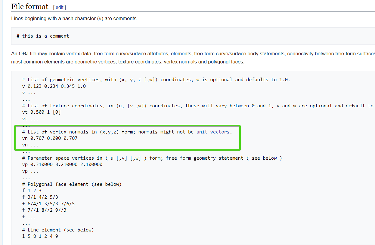
if you go back to even old model formats, they always specify vertex normals in the data sets
hmmm, if I remember correctly when studied procedural generation of meshes. I had to manually supply the face normals using a cross product calculation of the vertex positions
(that's wavefront OBJ format, which has been around forever)
well as I said, Unity may define it differently
i was trying to remember back from when i was writing my game engine but i can't remember that far back lol
maybe if I look at the code it will refresh my memory
wikipedia suggest that usually in computer graphics: Commonly, it is computed as the normalized average of the surface normals of the faces that contain that vertex.
right, but that's not genrally how it's represented in 3d modeling formats
Unity's documentation on meshes says: A normal is a vector that points outward, perpendicular to the mesh surface at the position of the vertex it is associated with.
it's an abstraction they may do in the engine
I'm gonna read up on Unity's documentation maybe they have something about this on their vectors section

Stack Overflow
I am working on a OBJ loader for DirectX 11.
In OBJ Format a square (two triangles) would look like this:
v 0 0 0
v 0 1 0
v 1 1 0
v 1 0 0
f 1 2 3
f 1 3 4
So at first the vertex data is given by ...
see in directx this example shows how they calculate the face normal from the vertex normals
each vertex has it's own normal, and this can be defined by:
- modelling package
- additionalvertexstreams (write new data in realtime)
- shader
so your mesh might or might not have the normal, but shader can calculate it too
it is only a direction in 3d
ah! I remember reading about normals for example when you want a smoothly shaded surface, vs a surface shaded per face
well given Unity's mesh importer pretty much always calculates normals, it would be rare to not have normals
you'd have to specifically set it to not
if I remember correctly the normals for lighting depended on the having duplicate vertices or not
if you want a flat look without using shaders you have to split verts because triangles interpolate the result of 3 verts (making it look smooth)
yep
splitting lets each copy of the vertice have different normals
so the face calculation goes a drastically different way for each face, even though they are adjacent
so yeah now that I put it through the thought experiment, i think i'm correct, it's vertex normals
aha! found this on Unity's site: Computing a Normal/Perpendicular vector A normal vector (ie, a vector perpendicular to a plane) is required frequently during mesh generation and may also be useful in path following and other situations. Given three points in the plane, say the corner points of a mesh triangle, it is easy to find the normal. Pick any of the three points and then subtract it from each of the two other points separately to give two vectors:
So I guess the face normals are calculated first based on the vertices? then each vertex is assigned that normal?
no the vertex keep their normals
but if a face normal is required that's how it's calculated
oh, I see
I can do a visual with Blender
one sec
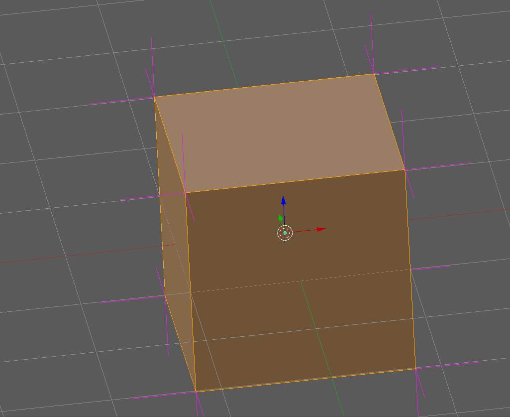
this cube has split vertices, so there's 3 verts at every corner
and you can see 3 vertex normals (pink lines)
so for each face, the 4 are averaged (because quads not tris)
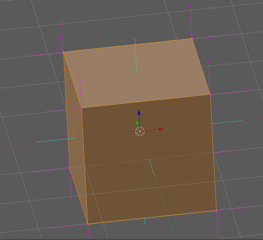
and that produces the face normal (cyan)
hmmm ok thanks
I'm asking about this to understand about the normals in a shader
float3 normal : NORMAL
that normal is per vertex?
if i'm not mistaken it's going to be per-pixel normal
which means the normal at the spot on the face that is currently being rendered
it depends where in the shader it is probably
oh, so each pixel has an interpolated normal based on the vertex normals?
Vertice or Fragment function
vertex function
for stuff like this i like to consult the great resource called Catlike coding
A collection of tutorials that cover how to write your own shaders in Unity.
their tutorials cover every aspect of shader creation from the ground up
yeah a while back I did a bunch of the shader tutorials basics from that site
I'm just trying to understand the result of this shader
`vertexOutput vert(appdata_full input)
{
vertexOutput output;
output.col = float4(cross(input.normal, input.vertex.xyz * 2), 1);

return output;
}
float4 frag(vertexOutput input) : COLOR
{
return input.col;
}
ENDCG`
i believe in the vertex function
it's going to be vertex normals
since that operates per vertex
about why on the sphere results in completely black color and on the quad and cube it doesn't
my initial guess was that the result of the cross function is always gonna be 0 on the sphere because the vertex position and the vertex normal point in the same direction
but on the quad and cube the normal points in a different direction than the vertex position
sounds like a reasonable hypothesis
am I correct in assuming that a vertex position is a vector that points from the center of the mesh towards the vertex?
no
the vertex normal is set in the 3d modeling software
so it could within reason point any arbitrary direction
but generally people don't want their models to be inside-out
so they do tend to point 'outward' so to speak
but it won't always be a straight geometric line from the object's center
it will heavily depend on the geometry and any normal adjustments they may do
it's not unusual for instance to use off kilter normals to give a mesh a softer look from certain directions.
it's simply a guide to the shader to say 'light should kind of go this direction'.
(and i say kind of because Normal maps can perturb the hell out of the mesh normals)
so... let's say I create a cube on Blender and set the pivot at the base and create another cube with the pivot at the "center" of the cube and the import those 2 models into unity. If I debug the local vertex positions for a vertex on both those objects...
the results will not be the same, is that correct?
vertex positons will be different yes
normals will likely be identical
(assuming you don't alter them)
alright! I think I got the grasp of it now
thanks a lot for taking the time to answer my doubts!
no problem
another way to look at normals is, they just give direction, which you can infer that 90 degrees from is the 'surface'
and this 'surface' is what the light will bounce off of
so using that you can calculate all the lighting related things
shadows, reflection, indirect lighting, color etc
the 'face' is after all just an abstraction of this direction
defined by the 3 vertices, and their directional normal vectors
yeah, I suck at doing stuff related with lighting tho... xD but I always look at a normal being a right angle of a tangent of the surface
even tho I think I don't fully understand how tangents work in 3D
in 2D is easy to visualize for me
yeah it can take awhile but stick with it, one day it will be clearer I am sure 😃
was fun though, I had developed an instinct for a lot of this over the years, but trying to put it all into words really solidified it for me 😃
yeah I find it "easier" to absorb if I ask questions about the matter, or read questions that other people have about the matter
thanks again my dear sir, may the shader gods bless you 🙏🏽
thanks 😃
Is anyone aware of a way to do shader replacement but instead of not rendering objects that don't match my tag, display them with their original shader?
only if they all use the exact same single shader without changes?
or some hackery with mpb
mpb?
material parameter blocks I think
btw is this HDRP ?
if so you can just use a fog volume under a plane for that, and you get the added benefit of using a 3d noise texture for caustics
I'm not certain if I will for my water as it's got 3d ripples, might drop the 3d ripples though
it is HDRP yes, and yeah the goal is not to use this water or anything, I just want to learn shader graph a bit better
yess, looks even better
with foam lines
hmmm, async PR for SG previews didn't really do much for the basic experience
it still stalls after each wire connection =/
it's one of the main issues on current experience with it
you get these long pauses after each step you make
tbh, I don't even care it compiles the intermediate results on fly, I wish I could disable it
on most graphs, I even hide all preview displays
so I'm really paying the compilation cost after each change for nothing
I don't think I got similar pauses on ASE or SF
ASE at least is instant (even with HDRP template)
it's joy to use
maybe this is a better place for this question.
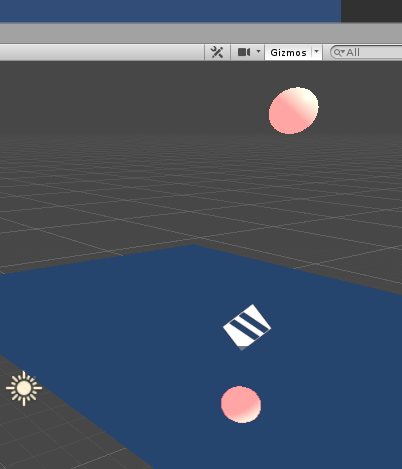
Any idea why my emissive material is not reflected properly?
HDRP 5.10, Lit material with Planar Reflection applied, all static.
probably a bug of some sort
that's with the planar reflection right?
quick test, it seems to reflect emission fine for me
is the emissive object baked?
static baked it's fine too
i'd have to know a lot more about your lighting setup to try to recreate it
hmm
the object is static, but maybe my emissive is not set to baked. probably that is why.
i just used default values
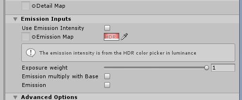
nothing special
also are you in forward or deferred
looks like i'm in deferred, the default
ohh wait, i forgot
you're in LWRP aren't you
i'm in HDRP heh
no you said HDRP
hmm
I am in HDRP. Doing some learning.
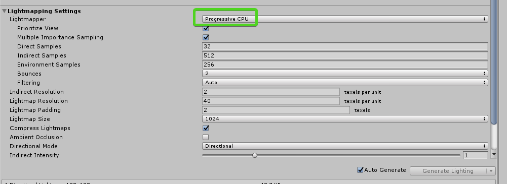
also I noticed in HDRP, lightmapping is slower (even without Optix) , and not progressive.
it is progressive
and it baked progressively
unless you deliberately turn that feat off
i should try GPU
gpu baker is slower on simple scenes at least
on mine it crashed when in HDRP
funny enough Progressive GPU takes 30 seconds, and Progressive CPU is like < 3 seconds
pretty sure he meant more of having it bake the viewport first
that was the whole point of progressive lightmapper initially
give artists close to instant feedback on the view first and then continue on baking the rest of the scene
something must be wrong with your settings,
even if i manually bake it's Progressive
did you turn off Realtime GI?
nah, default settings. only decreased the resolution. also this tiny scene
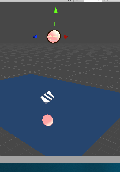
my scene is a plane and a sphere
very tiny
also default settings
are you sure you plugged the HDRP asset into the SRP slot? 😛
Anyways I feel we are talking about lightmaps in the shaders channel and the moderators are going to kickban us 😛
ceebee is a moderator 😛 I feel like discussion slides flexibly as long as it's fairly short and nothing else is going on in the channel
yeah the strange baking may the cause of the emission issue
just trying to get to root causes
yeah even changing the setting on the material didn't fix it.
im pisssseedd offffffff
i replicated my c# algorithm in my shader but get a totally different image result
SG's half resolution toggles probably coming up herre: https://github.com/Unity-Technologies/ScriptableRenderPipeline/commits/sg/precision-toggles

GitHub
Scriptable Render Pipeline. Contribute to Unity-Technologies/ScriptableRenderPipeline development by creating an account on GitHub.
it was on the gdc roadmap marked for 2019.2
hey guys, just added the shadergraph package to my project and this error started showing up, how can I fix this?
it also affected my cube script for some reason
@white sapphire sounds like you have missmatching LWRP and SG
you don't have to install SG separately, just install LWRP (or HDRP) from package manager and it picks the right SG for you automatically as it's set to include it in it's dependencies
also, 4.1.0 LWRP is really old now, newest is at 4.10.0
okay, thanks
Not sure if this is the correct channel but any ideas why shadows and the directional light work on my laptop but when I share my project with my friend via GitHub they do not work?
probably not sharing enough on github, missing files perhaps from project settings?
in shader graph I could get the depth texture by creating a property and setting it's ID to _CameraDepthTexture
but this is giving errors
how do I get the depth texture in shader graph? I'm in LWRP
and I enabled depth texture in my RP settings
There is a depth node
typically if you have to build it from scratch, it should be built in, and usually is.
Olento's depth-water fogging
Result because Olento Cares (tm)
It needs a little work with the perspective but you can manage that or someone can advise. Good start.
thank you
I'm messing around with Render Queues and ZWriting and trying to understand exactly how it works.
Do objects that come first in the Render Queue write to the Depth Buffer before other objects?
so an object on the queue 1999 will write it's depth values before an object on the queue 2000?
the queue is irrelivant if it will write depth or not
but in general, numbers after alphatest should not write depth
in SRP, a depth prepass might fog that issue a bit...
:D
what do you mean by irrelevant?
doesn't it matter what order do 2 objects have on the Render Queue if one of them writes to the Depth Buffer and the other one doesn't?
it might be a trivial question for many, but that's why I want to know how the writing to the depth buffer occurs and what order it follows
does it follow the same order of the render queue? do they write all at the same time? do they follow a different order?
the Unity docs are quite vague on this topic and I have not much experience with rendering related topics
it's weird, in LWRP I only get small line of foam
but in HDRP it's much thicker
with same shader, same settings, any guess of why this might be?
yeah well in HDRP you can set the sampling mode for the scene depth node
but in LWRP there is no option to change it
yeah my node is just this
I'm on LWRP 5.2.3 and SG 5.2.3
in 2019.2
I'm gonna try in 2019.1 maybe it's a bug with the SG version?
yea its just the version
there was some bug on old versions scene depth if I remember right
the sampling mode is in all pipelines in later versions
and HDRP scene depth was wrong
I will try 5.10
probably in your version
well, he's on LWRP
so SG and RP always have to match versions?
in general yes
but just install LWRP
it will automatically install SG
don't install SG separately
okay
if you only install LWRP it will automatically install core and sg at least as they are set to dependencies
since you are on 2019.1 you can see the dependencies on Package Manager on the package description
only reason to have the packages set separately is if you use some custom/local version that requires custom dependencies too
in other words, if you use SRP directly from git clone/fork or modify all parts yourself
i was wondering if you were going to notice the precision branch btw 😛
Does anyone know what the cost is of sampling neighboring texels of the same texture in the vertex shader? Is it something to worry about if targeting mobile? I'm currently sampling all 8 neighboring texels.
version changed fixed it 😃
You will pay per sample, 8 is a lot for mobile. What is the use case?
Stupid question about shader graph.
Is there a way for me to return a bool if a texture is or isn't null in the graph ?
im afraid not 😦
currently everything on the graph injects shader code, you need a UI only layer to do that.
@still orbit Generating a normal from a heightmap. I know it can be done with fewer samples, so I thought I'd check if performance will suffer for what I assume will be a smoother normal map.
Based on this snippet.
http://www.catalinzima.com/2008/01/converting-displacement-maps-into-normal-maps/
This is a repost from the old blog, since this is one of those interesting stuff, which weren't big enough to warrant a sample. Working on my VTF tutorial, I came across the need to apply lighting ...
https://docs.unity3d.com/Packages/com.unity.shadergraph@5.10/manual/Normal-From-Texture-Node.html
Heres a 3 sample version
Cool, I'll look into that!
Sorry, me again.
Could anyone suggest why I might have lost the shadows on my objects when using my custom shader unless i'm really up close? If I change to a different shader on the object which is casting the shadow, then it displays.
So I know my shader can recieve shadows ok. Any ideas?
@still orbit you saw my note about it? 😄
I saw it earlier but wasn't quite sure if it was for that specific use case before I saw the GDC roadmap
that seems more like something that bigger studios mainly utilize
I mean, it's possible to find some HC shader wizards that care about perf that much, but you'd really need to enforce the usage to get people to drop the precision voluntarily
I'm kinda dissappointed on the async PR so far
I was hoping it would make the SG smoother to use
but it's still same few second delay after each operation
I don't get similar experience on any other node graph shader editor, only SG
every operation I do stalls the editor few second or few
I don't even care about the previews most of the time, I usually disable the node previews asap (kinda wish it was optional to show them instead as it's extra clicks to hide them)
@fervent tinsel my sg experience is much smoother on LWRP
The whole editor experience is much better on LWRP for me tbh, seems much smoother.
that could be, I only use it for HDRP
but for example, ASE, even when I use it for HDRP shaders is butter smooth, every wire I drag registers instantly
but on SG it can take many seconds to register
Then in theory Unity Technologies themselves should be able to do the same haha, let's hope they improve it in the future
in SG, even if I made new property it stalls the editor
Yes same for me
and if I drag it to graph, it stalls as well
compiling previews?
it's not even doing anything at that point 😃
it is doing stuff 😛
"disabled"? 😛
I mean, previews hidden
master now has async compilation enabled, thus why i ask
does that need some setting somewhere?
and previously collapsed previews still updated
its automatic, you cant turn it off 😛
There is a setting yes
well, then it's not improving this
I'm running latest master
and I still get many second delays on operations
on 2019.2.0a9
wtf :/
you have this changeset?
https://github.com/Unity-Technologies/ScriptableRenderPipeline/commit/c9f098e81c68a755490e00ec17eed3bfffc010f4

GitHub
-
Async Compilation!!! Remove uber shader and compile all shaders in the background.
-
Only recompile preview shaders as needed instead of all of them for any change.
-
Dim previews during co...
yes
btw I tried that before too, before it was merged
I didn't really see notable difference in SG usage
well something is VERY wrong
let me do a quick demo
this is the SRP I run right now:
it's latest master with two PRs merged in
yea i see
the newest is just the BakedGI rename
hmmm, new property is now quick on new graph
but as soon as the nodes connect, it stalls
hold on im uploading a video to check this is what you see
wow why so slow :/
ah
but it's no excuse
we srtill have some optimisation work to do 😦
every other shader graph tool is instant, only SG slugs
I'll try on fresh project, one sec
well, few minutes rather :p
because it has to process SRP files again
hmmm i wonder why so slow now we dont wait for the compiler
I'll take clean master too
im assuming LWRP is much faster still
probably, I can try it in a bit
I did this exact thing at GDC on my 2016 MBP and it was faster than this, also HDRP Lit
yeah, that was on HD Lit
admittedly still half a secondish, but faster than that
can't you still do the UI updates async in addition?
it feels weird that UI gets stalled
Its an architectural issue
right now the master node is generating the shader
we plan to change it soon so the generator is orthogonal to the graph data
then it can run in a coroutine i guess, which would be wayyyy better
until then its better than waiting on the preview shaders for 4-5 seconds as well right? :/ lol
pretty much every operation stalls for second/seconds if there's things connected
I think it's bit faster on some with async but can't fully confirm it
I just wanted to try out the VFX Graph. After getting the Editor working (when upgrading from 0.5.3 to 6.x.x) the freshly created VFX doesn't play as it should. I am using Unity 2019.2, latest update.
Haven't edited anything yet.
@naive cipher try to use matching VFX graph to your RP
also we got #✨┃vfx-and-particles channel here which could be more suited for troubleshooting that 😃
@still orbit hmmm
SG wiring is way faster on new blank project
it's like that 0.5 seconds
I guess I'll try wiping the lib and see again, but I do have a lot of packages here, maybe something there is just slowing the whole editor down
@fervent tinsel it would be interesting to profile the editor and see whats occurring during the hang
unless you wiped the lib already 😄
I wiped it already
got distracted with other things (been testing triple-screen gaming setup)
I'll check what the regenerated library now does
it wouldn't be first time weird things happened with older lib
well it's still sluggish
and editor is idling at 3% cpu load
what's funky is that if I make say, new vector is constant in graph and hook it into active node (multiply in this demo), it stalls
but if I then remove the new wire and do it again for the same vector constant, it's instant
it's only slow on the first connection
I'll start deciphering this later by systematically removing things from this project
it doesn't do this on brand new project so it's happening because something I have here
but I'll do that later 😃
it's slow-ish on a simple change with my 2014 haswell i7 4400k and 16gb ram
which was instant with things like amplify shader ed but I know amplify had way less work to be doing)
GO GO GO OLENTO
ROOT OUT THAT SLOWDOWN
Olento is another name for the all seeing eye
@broken field you probably don't run it on latest master
the PR for async compilation just got merged in master, it's not in any real release yet
the old approach is known to be slow
huh I thought that cyan stuff was async...
I think it is
i think the real issue is the ui is blocked while it's compiling for shader graph and it should just let us continue.
but it only happens when you save the whole shader graph
this PR is for SG's previews only
so, things that happen on the graph only when you wire it
well I'll just have to be slow then while I wait :'( I'm on 5.10 + 19.1.b8
5.x.x will get a backport for this
PR for that is still sitting there waiting for approval
to be fair, my computer is more than capable of handling modern development. rapid ssd, clear drive, clear os, bags of fast ram and an i7 that probably still competes just fine

GitHub
Purpose of this PR
Take advantage of async compilation for the preview shaders (no more "Compiling Shaders..." dialog!) and render previews only when necessary. Removes the ÜberShader so ...
actually I can move to alpha if it's not shit (tm) - what's the current state of alpha for you?
still crashes many times a day on me 😄
yeah, I don't really use 2019.1 as much now
so can't really tell the difference
I've lately used 2019.1 mainly because been checking Unity's GDC goodies
almost all things run on 2019.1 there
I'm so used to reading "hold on" I now say it in a gruff pirate voice and imagine hanging off the side of an ancient galleon in a storm, my peg leg slipping against the soaked oak
HAULD AUUUN
It's not just me crashing with it thankfully, seems well-reported thus far
might actully be HDRP
Hey guys, just saying that I work all day on 19.1 and I haven't seen any crash but I had some when I was using HDRP and other. I think deleting library after big packages updates isn't something that I could not bear to do (because the crash were often after updates so my guess is that it's related to cache)
I also use 19.2 but not as much and it feels like a lil bit less stable
I have seen plenty of crashes on 19.1 while using HDRP. It's a crash-fest really. And yeah 19.2 would be less stable since it is still alpha. or are you saying 19.2 is more stable?
well HDRP is still preview :/ crashes in SG/LWRP are much more important to us right now...
so massive it's necessitated LWRP and SG
Hello,
I'm working on a shader that compute fake light influence. A fake like it's just a game object that set shader global variables like position, range and color. In my shader there is a specific part that represent how to take into account a fake light influence. So in order to have for exemple 2 lights, I put 2 instances of that sub-graph in my graph. Each sub-graph exposed properties that are fed up by the shader. So in my shader I have to declared light properties twice, like light_1_position, light_2_position etc. and then associate the right properties as input to each sub-graph. In my game I have 2 "fake light" scripts and each one will set global shader variables using a specific name (light_1_position for the first light and light_2_position for the second light).
Doing so works but it's really ugly and not convenient. If I want a third light I will have to duplicate all properties in my shader with the index 3 and add a third fake light sub-graph etc.
My question is, how can I avoid that ? Is it possible to make fake light informations available for the shader and having the shader be able to "iterate" throught" the number of active "fake light" and do what it needs to do ?
I think that what you'll need here are arrays and loop. And I don't think it's possible without writing a custom node.
Is it possible through a custom node to retrieve data from a MonoBehaviour scripts ?
Not directly, but through local/global shader variables, it should be possible.
ok
I read that custom node are about to change. What should I look for if I want to understand custom node in shader graph ?
I summon @still orbit to answer you on that
Thanks. I wait 😃
Is it possible to have a shader use other object's mesh data? For example have object A have the shader and use object B vertex : POSITION, the TEXCOORD, etc... ?
Uh, I "think" you could manage this with additional vertex stream but ... why not simply have object B use the shader you want ?
@amber saffron I'm not too experienced with shader programming so I did what I could to make a shader that renders an "intersection" between to objects on the surface of the object that's holding the shader. But the way I wrote it I don't seem to be able to have multiple intersections with one main object and multiple "intersector" objects
So for example for any intersection I'm forced to have 1 main object (holds the shader) and one intersector object
I do a discard based on the world positions of the shader multiplied by the matrix of the speheres
There's so much ways of doing what you're showing here that I have no idea how you did it and how I could help.
EDIT: Ok, you answered first
one sec I'll post the shader
use something like hastebin to post the shader
So, if I understood correctly, you'd like to pass the intersercting object mesh data to the "recieving" object shader, right ?
Oh it seems the channel doesn't let me copy and paste my shader code
yeah I would like to feed the matrices from multiple objects into the shader
I think thats not how you should do it here ... would be almost impossible to make work.
Os, so only matrices ? That easy then
materials[i].SetMatrix("_MyMatrix", intersectors[i].GetComponent<Renderer>().worldToLocalMatrix);
I do it this way for now
should I feed global arrays to the shader instead of having copies of the object with the shader each one receiving one matrix for each intersection?
Global arrays would probably help a lot yes 😃
One thing to have in mind when you do that : you can't resize a global array after it has been created. You'll need to restart the editor for that. So create with the maximum size you plan to have 😃
hmmmm I see
Is there a maximun size for a global matrix array that I can use in my shader?
I read somewhere on the Unity forum it was about 1k
but I'm not sure
Frankly, I have no idea
For textures arrays for example, it's limited by the memory it takes, but for matrices, that's probably not an issue.
alright thanks!
I'll keep on trying different approaches for my shader to see what performs better
because the way I'm doing it now it's fine for a couple objects, but not ideal at all when used in the hundreds/thousands
Not sure, but maybe using the stencil here could help ?
if you need that many objects you probably want a stencil buffer/depth based approach
And you could draw arbitrary intersecting shapes
@vocal narwhal @amber saffron I've tried an approach with stencil buffer shaders but I don't seem to get the ideal result with multiple intersections
the stencil and depth tests seem to kinda interact with each other and the shader I have uses at least 4 passes
it definitely performs a lot better tho
I'll keep on iterating on both approaches to see which one of them can work correctly and perform well. Thanks for taking the time to answer my doubts! 😃
here's the shader code in case anyone wants to see it
a note node yes
I mean you can group nodes
and add a title
but I'd like to add a small note or comment
to 'document' my graph
on our plan already c:
I could swear it was on some screenshot
yeah i saw grouping nodes shown in one screenshot
or keynote
maybe because they are working on it
group nodes already available, little sticky notes are in the VFX graph already
so porting those over are on the plan
Very welcome approx but is it just instruction count?
So people will still need to read up about the nuance of it all including bandwidth used etc... Still super helpful
@still orbit btw, I think I'm onto something on the sluggish SG UI
I tried bunch of things, slimming down my other project didn't help
until it occurred to me that the issue could be from specific HDRP asset settings
I took my the HDRP asset from sluggish SG project and placed it into new project that still had snappy SG and it did slow down
so it's some setting here
will go systematically them through to find which one
aaand, we have a winner (was suspecting this so checked it first)
if you make new HDRP asset and only swap it to forward only, SG goes all sluggish
(when the HDRP asset is assigned of course)
master 😄
ah 😄
it's the only place where the SG async compilation for previews is included atm
was testing it here
as I've been super annoyed by the delays
ooohhh yeah you right
but this issue roots way further than that
I'm pretty sure it stalls the SG wiring more even on older versions
as it's been super slow on some projects (and I use forward only a lot)
i guess that's why it got delayed :/
I'm afraid they say it's some architectural thing they can't do much about 😄
I'd really want SG to get to usable state for me on HDRP tho, I've kept updating ASE's HDRP template as ASE is still butter smooth
but it's pain to keep it up-to-date and amplify only covers the released unity versions so using bleeding edge HDRP is not really going to work nicely
and besides, amplify can't really keep up with all template types, it took them a long time to even support HD Lit template
yeah they did say they are not going to support alpha/beta stuff
they just supported HDRP with PBR template rather
well, on the bright side, at least it's not some weird package that's slowing my other project, was afraid initially it could be something totally different
ah that makes total sense
the master preview is generating the forward pass, which is a monster
ususally we only generate the deferred pass which is much quicker (many less variants)
is there anything that could be done with that?
guess what im going to tell you 😛
use deferred? :p
"it's some architectural thing"
precisely
the only thing we can do really is stop the editor from stalling as we process the graph
I still wish you could just opt out for preview compilation while wiring
we really dont want to do that tho :/
we just want it to not matter if you dont want it
which is doable
yeah, I get that, hope there's some reasonable solution to this
the stall itself is the issue
it doesn't matter if the previews update with delay
yea exactly
I'm on forward because the shadows are a lot nicer with time of day / open world
Can the shader graph not have a "force deferred" mode for previewing, or?
if not then I can of course switch to deferred myelf when doing shader stuff
it wouldn't give same preview for all things
no it cant force deferred
Guys please i need help
if there were any option, I'd want to get rid of those previews altogether ;D
not all HDRP material paths can run in deferred
node previews make sense but I never use the main one
np I can work with deferred for extensive graph work
I just see how the shader works on scene on the other monitor
Yeah I see it on same monitor
@still orbit bro i have a issue , look this is my little project " Car racing " the problem is the police car is Walk under the street and do not show up
please help me
So really just disable previews? but it would disable the preview for each node too?
@normal chasm that is not a shader issue
what issue?
position issue
sorry but iam biggnner
@broken field hiding the previews will not disable them
and they don't want to disable the previews
the police car is walk under street
no olento, I mean if they disable previews to accelerate it like you hint at, it would possibly disable the previews too
per node
its all or nothing isnt it?
so you will have no choice but to put it in deferred for a while
if they did that, sure
but sounds like that's not really being considered
I don't really mind if they want to do that as long as it will not stall the actual noodling
After a while doing some tests with the stencil buffer I managed to implement an intersection shader that works with multiple objects and the "intersection objects" don't show through each other. I've done it by using different Render Queues and different Stencil Ref values for every intersection
But my question is, can I have a reference value on the stencill bigger than 255?
since the docs say this: The stencil buffer is usually an 8 bit integer per pixel
does that "usually" mean that I can use more than 255 values?
8 bits means 0-255 (which is 256 values to be clear)
oh right! My brain is a mush right now xD
but would it be possible to use a 16 bit integer for the Stencil instead?
is there any way to overload that on the engine?
highly unlikely
I see, Google don't seem to yield any results on the issue
maybe I could use the Stencil ReadMask and WriteMask functions to selectively make use of the stencil Ref values
haven't used those functions yet so I'm not sure what they do
Quick question: when I use this line on the main pass of a shader
Tags { "RenderType"="Opaque" "Queue"="Geometry+1"}
and then this one in another pass inside the same shader:
Tags { "RenderType"="Opaque" "Queue"="Geometry+2"}
is that the same as having two objects with different shaders one on the Queue "+1" and the other on the Queue "+2"?
I'm trying to get depth in a water shadergraph in HDRP. Does anyone have that working? I'd super appreciate a peak at your graph if so
man, you're only the 5th person after that lately lol
maybe we should sticky it 😛
there I just pinned it
is a shadergraph node setup a member posted
I like that I have strength property on that screenshot that I don't use at all 😄
@stark hornet ReadMask is the bits which the stencil is allowed to read from, WriteMask is the bits the stencil can write to (if doing any operation other than Keep)
so as an example you could have the ReadMask as 128 whch is 1000 0000 the Ref value could be any number, but your stencil comparison would only be looking at the 8th bit
so ReadMask of 128 and Ref of 136 ( 1000 1000 ) with a stencil comp of Equal would pass
but if the Ref was 8 ( 0000 1000 ) it would fail
i think default read and write mask are 255 which is all the bits ( 1111 1111 )
it's also possible to control all the stencil parameters via shader properties not sure if you've been using that for the effect you're working on
but basically it would be something like this ReadMask [_MyReadMask]
same goes for the StencilOp's they can be set via the StencilOp enum as an int https://docs.unity3d.com/ScriptReference/Rendering.StencilOp.html

@stark hornet not sure on the Queue, last I remember Queue was part of the SubShader tags, dunno if that has changed
@uncut karma I can't thank you enough for taking the time to give me that lengthy explanation! 🙏🏽 Sometimes looking up shader-related stuff on the forums or around google is a bit confusing since some people have similar doubts but the questions/answers are either kinda obscure or not exactly what my doubts are. Thanks again for taking the time to explain it 🙂
and about the Render Queue on multiple passes, I ask about that because the shader I use for this Stencil implementation currently has the main pass on top (not defined between a Pass block), and after that, 3 more passes
2 of them just doing culling and depth buffer stuff
but the 1 last that I have has it's own Tags in which I define a higher Render Queue
So I don't know if that counts as rendering 2 different shaders even tho it's on the same file 🤔
this is the code "structure" of my shader file. Maybe the Tags line on the last pass is not actually functional? I've been mashing a bunch of stuff into the shader trying to make it work so that may be some leftover stuff from other shader I was experimenting with....
Oh nevermind about the Render Queue in a pass instead on the Subshader. The shader doesn't give an error but it also doesn't affect the Render Queue at all
I just checked my material and if I only define the Render Queue in a pass, let's say to the queue 2001, the material actually shows the queue as 2000 which I assume is the default if no queue is given on the subshader
strange how Unity would let me put that Tags line with a Render Queue on a pass but not complain about it...
Hi,
So here a screenshot of what I succeed to do so far but in way that can't be right. Let's imagine there is only the ground and the lights. The lights are hard coded nodes (the same ones for bot, just a duplicate) in the ground shader. In the game I have 2 GameObjects with the same script, FakeLight. The FakeLight script will set Shader global variables : LightRampTexture, LightColor, LightRange and LightPosition. Actually there is an index property that is append to variable names in order to differentiate the two lights variables in the shader.
Problem is that I have to duplicate all nodes relative to "light" as much as I want lights in my shader and do the same with properties that fed up those nodes.
For example, with two light, I have to declare in my shader LightPosition_1 and LightPosition_2. If i want a third light I will have to declare LightPosition_3 and be sure to use it to fed the right node.
it's not really convenient. I tried to create a sub-graph based on one light nodes and duplicate it in my shader - it simplify a bit the shader but I still have to declare all variables and plug the right one to the right sub-graph.
Would it be possible to make the shader automatically "aware" of how many "fake light" are in the scene and try to process them ? I'm completely new to shader and can't find a way to achieve that.
Thanks
So, couple of questions for you shader gods.
I want to either of the following:
- A surface shader that is unlit.
- A vertex/frag shader where I can get information about the normal of a polygon.
The intent is to color a polygon based on its normal (For example, grayscale based on curve, so on a sphere you'd see polygons that are facing the front of the world as brighter shades towards white and those that are facing farther away from you as darker shades towards black)
Unfortunately geometry shaders aren't an option as some target devices for this project don't support it (iOS specifically).
Any suggestions on how to achieve either of those?
is the problem that you want to colour polygons individually and not an interpolated result?
While using properties of the polygon (Or vertices that make it up) rather than those of a single vertex, yes.
To be clear, the normal shader pipeline will take the interpolated result of all the properties of the polygon - not a single vertex
you're looking for the entire polygon to be shaded based on the face normal, not an interpolated vertex normal - without splitting the meshes triangles?
Because if you're just looking to shade based on the normal direction of what's rendering you do not need a geometry shader
just google "unlit fresnel unity shader" if that's the case and there'll be a lot of results
I'm looking for a non-interpolated solution, yes.
Will Fresenel cover that?
Basically what I'm looking at is this:
I have a mesh that was a flat plane.
I created a bevel effect for it by mesh generation in C#.
Now I want to paint the angled parts in black, and keep the polygons facing the camera as white.
You'd only be able to get a non-interpolated result by making the mesh's polygons not share vertices (and each vertex is pointing the same direction) as far as I know if you don't have access to geometry shaders. It's still using interpolation but the result is as if you weren't. And in that case seeing as you own the meshes' pipeline you may as well just make vertex colors a part of that pipeline imo 😛
perhaps someone will be able to help further if I am mistaken on that and they have a way I've not heard of, but as far as I know you cannot get a non-interpolated result in either shader approaches
That's an interesting point actually.
It is why Unity seperates the shared vertices if you have hardened normals
I was using the extrusion example of Unity's procedural mesh generation asset as a baseline, and noticed it had a bunch of duplicated vertices after extruding the mesh.
I wrote code to optimize and discard the duplicate polygons, connecting polygons that were using them to the same polygon, so that the polygons would end up stretching when a vertex was moved for the bevel.
I guess that there was a purpose for the vertex duplication after all.
hah, probably! Anyway, good luck 😃
Thanks.
And just a heads up, I actually found something interesting in regards to the interpolation.
Apparently you can use a "nointerpolation" prefix on the member of a struct used for a vertex shader output, like so:
struct vertOutput
{
float4 pos : SV_POSITION;
nointerpolation float3 normal : NORMAL;
};
apparently you can use partial derivative functions to get face normals too
How's that?
I'm not sure about the compatibility of nointerpolation, I certainly haven't tackled this problem for a very long time
float3 y = ddy(IN.pos);
float3 normal = normalize(cross(x, y));```
Once again there's platform compatibility issues and it'd probably be more performant to split verts anyway I'd imagineBut this stuff is getting beyond my knowledge anyway, I can't even tell you what the platform restrictions are for these things without researching them properly myself - if you can't find more information yourself there's definitely others around who will know 😃
Platform compatability issues with the nointerpolation or with the ddx/ddy thing?
both!
Haha
Damn
Well, thanks anyway. You already gave me a lot to think about 😃
Any ideas about the other approach with making an unlit surface shader btw?
I have zero experience with surface shaders 😛
Too easy, eh? haha
If I've needed a surface shader I've always just used a shader graph plugin
Quite honestly, I can't wrap my head around how to work with that node graph ¯_(ツ)_/¯
which probably didn't even generate a surface shader to be honest but 🤷 it's not ever been something I've been concerned with
They're a great way to get into shaders as it's pretty approachable to make rather complex effects and there's a lot of people who've come from art who have approaches you can look at from all sorts of other software like Substance Designer or whatever Unreal's shader graph is called
Of course. It's a fantastic tool. I'm just too stupid to get it haha
I can get behind the code, but the graph just confuses me.
just wish the shader graph was`t as limited as it is
@vocal narwhal nointerpolation doesn't seem to work on my Galaxy S8. Guess you were right.
@plucky bone Wait. I can set colors of a vertex regardless of the material used? That's brilliant.
Yeah
If you shader supports vertex colours that is
They're interpolated between vertices though
So you're going to need those double verts
So it's basically the same problem 😅
Well
You're doing this the difficult way by trying to extrapolate the data that you already had before
And writing a shader or something that is doing that extrapolation is probably less performant than just having those extra verts
Fair enough.
But the problem with the extra verts is the fact that other polygons that should be affected by vertex position changes, aren't.
Though I guess this is solvable in the same way that the optimization was.
Any idea how to access the vertex color data in the shader btw?
struct vertInput
{
float4 pos : POSITION;
float3 normal : NORMAL;
half4 color : COLOR;
};
Doesn't seem to work
that should work I think
Of course it does. I just forgot to mesh.SetColors () after setting them.
Thanks
Just wanted to let you guys know, I did the duplicate vertex thing and managed to get it to work (Ignore the fucked up polygons going through the eyes).
Nice
I made this intersection shader using the Stencil Buffer, a sphere is holding the Intersection Shader, and 3 cubes have standard materials
would it be possible to feed the textures and possibly other data from the other 3 objects into the Intersection Shader object?
I'm trying to have a "cutout" effect that shows the intersected parts of multiple objects via the Intersection shader
Something like this?
https://twitter.com/minionsart/status/1005782385508716544

yeah something along those lines
I'll check it out! Thanks for the link 🙃
even tho I think with my shader "swapping" textures won't work
but I guess I would need something similar to that example that you linked
Yeah, it would be easier to have the things being affected handle the transition, rather than the sphere.
Yeah, ideally that would be what I should make, but my shader knowledge is limited and for now I came up with this approach that uses a custom shaped object (in this case a sphere but my shader allows for any mesh) to hold the intersection shader,
I need to do some experimentation to see if I can invert the effect
Oh, hm, yeah having any shaped mesh would complicated it.
The link I posted assumes it's a sphere so that you can just use the radius from it's world position.
My shader knowledge is limited too, but perhaps you can use the shape you have as a stencil. But that would also mean having two of everything?
yeah I did something with duplicating objects for the same effect but the performance would not be good with my intended use, which is having hundreds of intersections at the same time
I decided to make it this way so I could use any mesh as a mask, and also having the option to make the "target" objects invisible
quick example with a complex mesh
and this with transparent target objects
so that's why I was thinking about maybe getting the data from the target objects (the 3 cubes) and feeding it to the mask objects
something like taking the color of the pixels/fragments from the textures in the target objects, and feeding them into the stencil masks with the world position
or something like that... but I'm not sure if that is possible or not
Yeah ... I mean, I can only think of stupid ways of doing it, like taking a screen pass, making a mask by colour matching those red values, then somehow adding in the revealed view onto the hidden view via that mask.
But yeah, unfortunately, I have no idea. But there's lots of really smart shader people here. I'm sure someone will have an idea. 😮
@frigid zinc nope, do you have the link by any chance? or what is called on the store?
might give you some ideas
it only uses cubes and planes to cut as far as I know
but techniques shouldn't be dissimlar
Maybe I'm wrong, but I think those kind of "cross-section" shaders use a discard method that may not be suitable for what I'm trying to do. But I'll keep doing some research on it and see what other people are doing with this kind of stuff
I any other shader wizard can point me in the direction of similar stuff I would greatly appreciate it 🙏🏽
possibly, but I was more thinking about how to fill in the cut areas
it's true a plane is probably a lot easier than an arbitrary shape
yeah I need arbitrary shapes as masks to have more tight control over it. Even though I would settle for spheres if that would help me achieve the desired result
for filling in the shapes I don't have any plans for now since maybe I don't actually want to fill them, but if I decide on doing that I probably do something like this
https://steamcdn-a.akamaihd.net/apps/valve/2010/gdc2010_vlachos_l4d2wounds.pdf a Valve shader tech to "fill" holes
this is kind of ringing bells about SDF shapes
@frigid zinc SDF?

This tutorial explains how to create complex 3D shapes in a volumetric shader, using signed distance functions. Unity tutorial and code provided.
yeah they are mathematically generated shapes
and because of that they can be merged easily
made me wonder if they could be subtracted easily...
just a random thought that popped in my head hehe
oh! Interesting
maybe I can implement that in my system so I don't need to use meshes as masks and can just generate the shapes with SD functions
but that would open another problem: how to conform those arbitrary shapes to the surface of the target mesh
with simple objects and flat surfaces I guess it would be easy... but I can see how that would get quite complicated to do with more complex meshes
that's why I settled for now on using stencils, because I can use any mesh as a mask (with some exceptions)
yeah can I ask exactly what you're trying to accomplish with all of this?
it sounds insanely complicated hehe
I'm trying to create some kind of splatter / decal system
it's also like a "fluid" simulation... it's kinda hard to explain
but think as if painting on the surface of invisible objects
okay, but why would decals need to bore holes?
I'm not carving any holes into the target meshes
all I do is "paint" their surface
this is an old gif of the first rough implementation I did for this that used just geometry duplication (as you can see for the "jagged" look that it has)
okay, i guess i was thrown by 'cutout'
i thought you wanted to cut the red parts out of the solid meshes
if you're just looking to paint, it looks like you're mostly done
yeah that's the issue... I'm not looking to "paint" but more like "reveal" what texture is under the painted area
ah ok
so like Minion's where he has mask reveal
now i get it i think
that is challenging to do arbitrarily
yeah it's almost exactly like that link of the Minions tweet, but my approach is a bit more complicated
I'll give a try to that texture swap approach, maybe it fits my system, who knows
I'll keep on learning shaders and iterating on my shader to see what I can make out of it
but for now I'm happy with what I have because I can go back to actually prototyping the game I'm working on
anyways thank you folks for the tips and help! If anyone else can throw some more info at me, all is welcome! 😊
np, and good luck
hmmmm... https://user-images.githubusercontent.com/6877923/54675901-c690b900-4aff-11e9-8854-be78d9e8f8a5.gif


GitHub
Purpose of this PR
Add exposure and HD scene color nodes
Will need to update the emission graphic test when merged
Testing status
Katana Tests: Running
Manual Tests: What did you do?
Opened t...
Stop spying on us @fervent tinsel !
Out of curiosity, why that "hmmmm" about the gif ?
mainly curious about that scene color node on regular materials
It's almost the same as the generic scene color node => available for transparent materials to grab what has been drawn behind. But in HDRP, it allows to sample the mips, and enable/disable the pre-exposure.
ah, that's why I got deja vu 😄
(I think someone demonstrated similar thing for LWRP etc using the old twin stick shooter sample from Unity 3 or 4)
related to scene color, was bit disappointed that gdc 2019 roadmap talk didn't address SG PP at all
it's kinda huge thing that is missing now
ASE implements PPv2 support nowadays + there's community members SG mod for it, but there's no official built-in solution
hope HDRP PP and LWRP PP (when it's done) enabled Unity to do this eventually
That's still in the "how do we do that" stage I think. In HDRP for example, PP are mostly done with compute, and doing that in SG would mean beeing able to output compute from it.
I hope some day 😃
@amber saffron is that PR address the issue when using color node in HDRP the result are darker/underexposed ?
especially when the scene are using physical light value
Yes
nice, then i finally can get rid the exposure node for my water 😄
why not one unified node editor for all kind of stuff(c#, compute, shader)? It seems you doing all the work twice or more when new node editor is appeared. It also makes it harder to communicate between editors(like ability ot make custom shader graph for vfx)
The node editor system is indeed common. But each of the editors you mentioned need different outputs, so can't share most of their features.
Visual code => I have no idea how it will work, but I guess it would be evaluated realtime.
Visual Shader => Outputs HLSL code compatible with shaderlab
Visual VFX => Outputs compute shaders, and c# cpu code (cpu/gpu optimisation or CPU fallbacks for mobiles for example)
All I know is that top people are sorting all that
waves his hand
I'm just happy Unity is so far beyond my own personal capability now. It really wasn't a few years ago
So I can't complain :D
the hmmm for me is how are they doing that cool effect on the plane, it's like distortion and blurring mixed together.
Hi everyone. It is the first time I write here but I'm getting an error that is driving me crazy.
I have a pair of shaders that work together. The first one writes on the stencil and the second one checks the value of the stencil and gets drawn if an equal comparison is true.
Everything works fine in the editor but on the Android build the stencil comparison doesn't work. It acts as if the comparison was always true.
It's a weird issue but any help or insight would be much appreciated 😃
Are they on the same render queue? Could be a sorting issue
wonder how long till this gets merged in https://github.com/Unity-Technologies/ScriptableRenderPipeline/pull/3233

GitHub
Purpose of this PR
Why is this PR needed, what hard problem is it solving/fixing?
Fixes 1136706 - Baked GI Node Serialization Issue
BakedGINode was also a casualty of the mass rename with INode. Th...
guys I have 1 single mesh with no sub mesh. In this mesh there is a transparent glass. There is one single png texture file for this mesh with an low-opacity area for that glass.
is there a way with shader graph to show this transparent glass effect
there is an alpha channel to show the greyish area for the glass but i dont know how to make use of this alpha channel
obviously i could split the glass into a sub mesh and apply a material with transparent surface
but is there any way i could just use 1 material, 1 shader and 1 texture to do this?
Hello guys,
I'm still looking for a better way to achieve my fake light shader. Because I'm completely new to shader I might be about to say something stupid, but I have a question:
Would it be possible to have all my fake light, which are GO with a script describing a light properties (range, color etc.) to "write"/modify a Texture2D ? The point would be to have a texture that would represent the screen - each pixel would represent the result of lights. Then this texture could be read in the shader to compute if the current pixel should be influence by the light, how much, then determine an offset for the ramp texture or whatever.
Is that possible ? Is that clever or completely stupid ? Is there some tuts you could point to me ?
Thanks
@agile arrow Set your master node to be transparent, and plug the texture with opacity information in the alpha channel. That should be enough.
@grand jolt Yes this is possible, but how you describe it is inefficient / complicated. Imagine, if one screen pixel is lit by two lights (or more), what data are you going to store with 4 floats ?
I suggest your either use shader arrays to store the light datas, or if you want to go for a texture, you can layout your informations, like, each line of pixels stores the data for a single light (color / range / position ...), and you can use Texture2D.SetPixel() function to modify the texture on the fly.
Saddly, the best method after this is to use a loop in the shader to calculate for each pixel the influence of each light. And if you're doing it with shadergraph, that's going to be impossible right now.
But with SG, you could use a subgraph to do the maths for a signle light, and in you master graph, just put multiple of those (unless you plan to have an enormous amount of lights in your scene).
I was actually looking for a way to not have to hard-coded the number of light.
I did not thought to use the Texture2D to store all light properties but the result of the lights. I mean, having like a black texture and then modify RGBA value according to how many light "reach" that pixels. So the Texture2D would act as a texture that in real time represent what part of the screen is enlightened by the light and the shader would have read that texture.
So far I declared all my light in the shader, should I keep that way ?
@amber saffron I dont understand what do you mean by plugging the texture in alpha channel. Sorry Im not experienced with Shader Graph yet. My texture got all other textures included but i only need the low opacity area to appear sort of blended.
I can set the master node to be transparent. But by doing so will change my entire mesh into transparent
Maybe I missed something, but that My texture got all other textures makes no sense to me.
Thats how shader and materials works, either all the mesh is opaque, or transparent, you can't have if to be opaque and transparent based on a texture, with a single shader.
the texture includes other areas, not just the glass area is what i mean
it would be best to split your mesh into opaque and transparent areas
But, you could use alpha clip and TWO shaders/materials to render the object twice. One opaque cliping transparent pixels, and one transparent clipping opaque pixels.
Anyone here have some experience with compute shaders?
A bit.
I am trying to sample blue noise in my shader
i am sampling in screen space
so uv is a pixel point on the screen
but I also want to jitter the blue noise after each frame
@amber saffron thanks now i got what you mean
float blueNoiseCalc() {
float2 noiseCoord = (_Pixel)/ (1024).xx;
float blueNoise = tex2Dlod(_BlueNoise, float4(noiseCoord, 0.0, 0.0)).x;
return blueNoise;
}
is how
i am sampling now
I'm looking to offset the _pixel value on each frame
my previous noise calcs
float rand()
{
float result = frac(sin(_Seed / 100.0f * dot(_Pixel, float2(12.9898f, 78.233f))) * 43758.5453f);
_Seed += 1.0f;
return result;
}
gave good variation, but obvious noise
thoughts?
When you say that you want to offset the pixel value, I guess it's not a simple UV offset, but more an noise animation from time ?
i am path tracing so it needs to ultimately trace every pixel multiple times and converge in x samples
alsmost need to scroll the ov the bluenoise
uv
Sorry, I don't get the issue here then. the blueNoiseCalc() you showed before should do the work, and offseting the _Pixel value by a float2 doesn't seem hard ... Maybe I'm just not understading what you want to do
in theory it should be so simple
but my results are bit broken
thanks, it helps just putting it down in chat
@amber saffron I also want to ask
I have a triplanar shader graph atm
is it possible to create a splat map with texture array onto this triplanar ?
I would like to paint on top of the custom mesh/terrain to create variation on the terrain texture
Yes, it's possible
can you should me how could i set up texture array to form a splat map that I could use the custom texture to paint ?
I follow this tutorial to have the triplaner shader

Welcome to 2019! I'm only nearly 3 weeks late. In this tutorial we're going to build our very own triplanar mapping shader using Unity's Shader Graph. I'm us...
You shouldn't have to make so complicated stuff.
Check out the triplanar mapping node in SG, it's a base triplanar for a single texture.
Use that for each texture of your array, and mask with the splatmap
Probably suboptimal depending on what you plan to do, but it's the easiest possible setup.
but how can i use it to paint that custom texture?
Ow, you wanted to paint the splat within Unity ?
That's not built-in, and not so easy to do. But it's way easier to paint vertex colors, that could be used instead of the splat map. Polybrush is here for that.
I have a big terrain modeled in Maya
I want to use triplanar shader to reduce the need to create uv map for this terrain
but there will be areas that I want to paint or put a texture on top of it
like a road or a path, or a patch of dirt
so far I have known of splat map, decal
Like I said, vertex painting could be a solution.
ok let me try that. My terrain is quite low in poly count so Im not sure if vertex paint could yield good results.
Your other option is to use some assets that allow texture painting in unity.
I just saw Unity having render graph branch.👀
Wondering what would be its use case..
I think it may be something like Frostbite
Frame graph
That's should more be in #archived-hdrp but you're right, it's inspired by Frostbite's Framegrah.
To summary easilly, it will help to manage the rendering ressources by moving the current renderloop code in different "blocks", and will also allow to more easilly extend the current pipelines.
That sounds great. Can we use it for hdrp or is it for custom srp use only?
You should be able to use it to HDRP. HDRP will move to rendergraph as it is put in place.
Okk...I have one more question. I will post it in the #archived-hdrp .
@amber saffron framegraph eh? sounds fancy. Can you give me a quick use case for it in HDRP?
I can't link to a message in an other channel (or I don't know how), but stramit answered what is a framegraph in #archived-hdrp
Electronic Arts Inc.
Talk by Yuriy O’Donnell at GDC 2017.
Nice but what is the use case with HDRP? just substracting some blocks we might not need? seems like a higher level version of just editing SRP without needing source. It could be a nice way to get HDRP running on switch like an uglier version of LWRP (you'd need to turn off so much stuff that it probably looks worse in the end)
Actually I think with limited settings it could work alright ish sort of makes vague hand movements in the air
Don't think of it like a visual editing tool, but like a graphic view of how your frame is rendered, and how the ressources are allocated/reused. This will allow to better optimise the rendering and ressource, as to more easilly add steps in there.
Oh wow that is very nice, so if I am making an open world game with time of day (I am) then I can perhaps shuffle things that might be a bit more relevant to me? for example I ditched baked GI because it makes no sense for unity with big environments and I could just remove that "block" ?
primitive and probably not right but I think I feel where you're coming from
That's the idea, even if I'm not sure if your specific example is possible 😃
hey! does someone use a custom shader for grass? or do yo use the unity nature build in?
so this is the replacement for Command buffers for HDRP?
How should I go about modifying the ParticleLit HDRP shader to have it use the brightest it can be?
I have snow particles, but they look bright only when seen from the side of the light. I want them to be always bright when near a light
@main blade this is basically what i do when needing blue noise that is 1:1 with screen pixel size and also offset each frame ```
//keep 0-1
float2 shift = frac(_Time.xy);
//then scale by with and height of the target texture
shift *= _ScreenParams.xy;
shift = floor(shift);
//how many times the texture fits into screen if 1:1
float2 screenByTex = _ScreenParams.xy / max( _BlueNoiseRGBA_TexelSize.zw, float2(0.0001,0.0001) );
float2 screenCoords = (uv + shift) * (screenByTex);
return SAMPLE_TEXTURE2D_LOD( _BlueNoiseRGBA, sampler_BlueNoiseRGBA, screenCoords, 0 );```
@uncut karma thanks
that helps. will figure it out, but as posted I get some strange glitches
glitch render
random sampling
oh i didnt see it was a compute shader, what is _Pixel being set from?
_Pixel = id.xy;
from the main thread
i have uv transformed to [-1,1] for some other calcs like so
// Transform pixel to [-1,1] range
float2 uv = float2((id.xy + _PixelOffset) / float2(width, height) * 2.0f - 1.0f);
where width and height is the resulting render texture
Game of Life is invading my pixels...
Someone familiar with the method GetComponent<Camera>().SetReplacementShader() able to help me out? I'm at an absolute loss right now
@main blade im less familiar with UV's in compute shaders, usually i just use uint and Load, maybe this would work ```uint noiseWidth;
uint noiseHeight;
_MyNoiseTex.GetDimensions( noiseWidth, noiseHeight );
uint2 noiseLoc;
noiseLoc.x = id.x % noiseWidth;
noiseLoc.y = id.y % noiseHeight;
float nois = _NoiseTex.Load( uint3( noiseLoc.xy, 0 ) ).r;```
if loading vs sampling worked then instead of directly using id.xy there, it could also have an XY pixel offset added for shiftin/animating before the mod
so whatever value SV_DispatchThreadID is would be kept within 0 and noiseWidth (Exclusive, so 0-511 etc)
this has given me the best results
float blueNoiseXRA() {
////keep 0-1
float2 shift = frac(_Time.xy);

float2 screenByTex = _Pixel.xy / max(1024, float2(0.0001, 0.0001));
float2 screenCoords = (shift) + screenByTex;
return (tex2Dlod(_BlueNoise, float4(screenCoords,0,0)).a);
}
standard noise
XRABlueNoise
but for some reason everything seems a bit overexposed
sampling feels better though
oh interesting, well if you know that 1024 is the noise textuer size you can remove that max() it was just to avoid potential divide by zero
standard noise might have had negative values in it which were darkening the output
maybe it was between -1 and 1 random
this was original
float _Seed;
float rand()
{
float result = frac(sin(_Seed / 100.0f * dot(_Pixel, float2(12.9898f, 78.233f))) * 43758.5453f);
_Seed += 1.0f;
return result;
}
seed being set by unity random.seed
initially
so it should still be 0-1
oh yea, hmm, how is the noise being used, is it jittering ray start positions?
// Roulette-select the ray's path
    float roulette = noise();

    if (roulette < specChance)
    {}
noise is compared to energy of a ray
then ray calcs are done
ah ok, one thought is maybe sRGB vs Linear texture (the noise texture)
but i think if it was the alpha channel that is linear either way
the blue noise I am using makes use of alpha channel
its definitely sampling the noise, but still something strange going on
thanks for the help.
float2 shift = frac(_Time.xy);
was the solution I needed to offset the uv
seems there are some issues either with the pixel values
or elsewhere
In the shader graph documentation they say for the scene depth node
'if depth buffer is unavailable node will return mid grey'
and I indeed get a grey output
but I'm in LWRP
and
and depth texture is enabled
was going to ask about those 😄
is it broken on the final shader or just in preview?
could be just preview issue
I get color variations based on depth
I dunno if you can even preview such data there
I mostly hide those previews anyway, unless there's specifically some effect I'm building where it makes sense to see them
also just to check
if I have a linear depth output between 0 and 1
I should/can multiply by the far clip plane
to get world position depth
so if the far clip plane was at a distance of 500
in my experience (on HDPR tho), I had to do that manually for Linear01 even tho I think Kink3d said it wasn't necessary... if you use Eye option on depth node, you can use it as is
I then get depth between 0-500
it's LWRP in my case
and eye gives me weird results atm
but I'll play around with it a bit
if the multiply by far clip works, why not use it then? 😃
yeah! and I just tested, it works the same with eye haha
I'm starting to love this shader stuff, shader coding isn't for me I think but shader graph makes me happy
@halcyon siren what's the issue? The docs explain replacement shaders pretty well now - they used to suck
@halcyon siren watch this https://www.youtube.com/watch?v=Tjl8jP5Nuvc

The third installment of my Shaders series! In this episode, we implement some replacement shaders and explore how they can add some unique effects to your g...
then read the docs https://docs.unity3d.com/Manual/SL-ShaderReplacement.html
For the replacementTag variable, the string you provide is the tag Key, like "RenderType" and each of the original shaders need to have matching associated Value (eg. "Opaque") in the replacement sub shaders or else they are not drawn.
so me again with the water shader
so I'm getting depth values, but as you can see the depth is not seen from the 'top down'
it's viewed from the camera
is this how it should work for water?
I have these nodes atm
ah!
found cool trick online
to fix it, now this is how it should look like
I divided the output by do product of normal vector and view direction
I actually wondered that myself too
can you show the final graph? 😃
for that part
well, it should be obvious, I'll try
I actually opened my old project where I did the original graph posted a while ago here
I do remember seeing that effect at really shallow angle and low water level
but I can't repro it now
ah, I see it now
So using the node setup I posted, I have this issue
where depth values change when I zoom in
I don't get why this is happening..
is it because my scene depth is in 'eye' mode and 'screen position' is in 'raw' mode?
Yeah need it normalized I guess
Can you use a custom shadow pass to write a different shadow attenuation for a mesh?
use case: Artist wants a certain class of objects in our game to cast a weaker shadow than is accurate
seems achievable, lets find out
might be interesting to see a kalliroscope done with unity's shader XD;
(my earlier post turned out to be non functional btw)
I can't figure out what the fragment shader in a shadow pass actually does
cause it appears to do basically nothing
😛
@fervent tinsel
here is another method to read depth
it's far less intuitive imo
but it doesn't seem to have viewing angle issues
I should be able to fix the viewing angle issues with my other node graph though