#archived-shaders
1 messages · Page 106 of 1
ic, ty for the help 
You'll have to excuse me if I'm asking really beginner level questions. I know GLSL, so HLSL features are pretty foreign to me.
For a surface shader, what is uv_MainTex variable in the Input struct exactly? obviously you can use it in the tex2d function to map a texture to your UVs, but I don't understand what it is I'm feeding it. uv_MainTex has to share a name with a texture, and I don't get why. What is it representing by declaring a variable that has my UVs coupled to a Texture's name?
I'm really expecting it to be the UV coordinate for this screen pixel, but I've tried making a color as (uv_MainTex.x, uv_MainTex.y, 0), and it doesn't work at all the expected way
Texture properties typically have tiling & offset fields so you define it that way in surface shaders to apply those
In vert/frag style shaders the equivalent is something like TRANSFORM_TEX(IN.uv0, _MainTex_ST) (or IN.uv0 * _MainTex_ST.xy + _MainTex_ST.zw)
Mm, okay, so it's coupled to the texture because the texture is transforming UVs under the hood
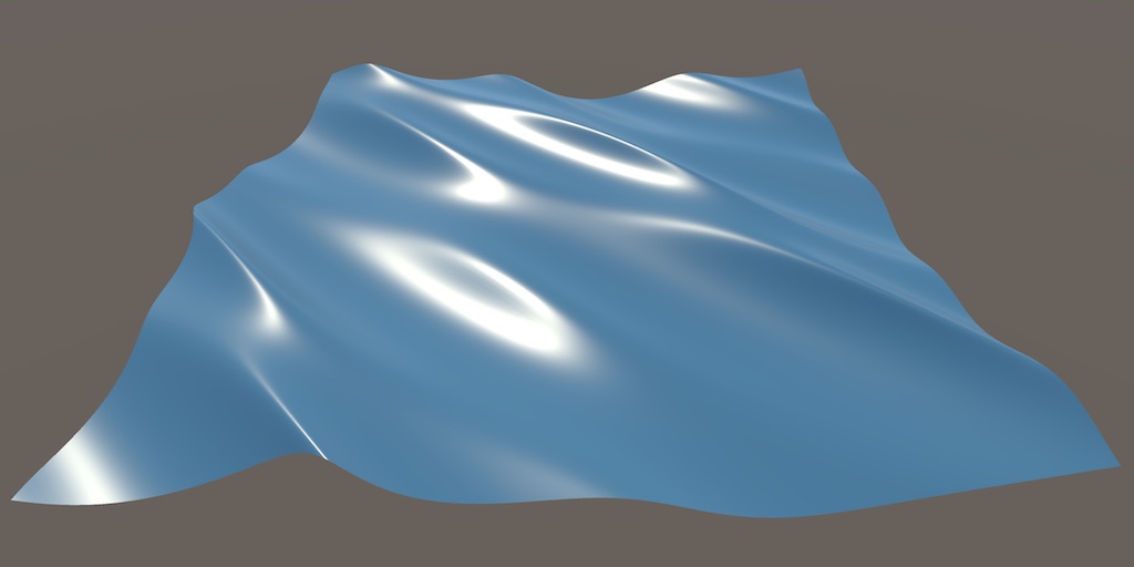
okay another thing so Im trying to make plane animated by a vertex shader (a sort of wave simulation) and I have impleted a basic diffuse, specular and ambient lightingShader but I can barely see the shadows and I have no idea how to make them more pronounced ive once again tried a bunch of things this is how it looks curently

this just looks so blegh at the moment and I have no idea how to improve the visuals further as I feel my foundations are kind of rough
You'd want to look into calculating normals to match the vertex displacement. This tutorial might help : https://catlikecoding.com/unity/tutorials/flow/waves/
A Unity Flow tutorial about moving vertices to create waves.
ive already done that and read this like 5000 times in the last 24 hours :DDDDDDD
the normal are absolutely corectly calculated I think you can even see it because of the incoming light reflection
I also spent 3 hours making sure this is the case so im like 99.9999999% sure
because the normals were fucked before hand
heres a better view to get the idea

this is the lighting part of my shader what the first part I should improve?
im setting a texture2d with negative values but when i apply and sample the values become positive, is there no way to pass a texture 2d to a shader that keeps the negative numbers? I need to use -1 to represent clip
I dont think texture sampler can sample negative number, thats why normal maps need to be unpacked (iirc its remapped from 0~1 to -1~1)
oh 😦 lame
You could remap after sampling, from 0-1 to -1 - 1. use the 0.5-1 range of the texture like standard, and below 0.5 would be turned negative
Or a second texture with only the negative values, encoded fro 0-1 and then subtracted from 0
There are also signed texture formats, like this page lists that can deal with negative values directly. Only applies to textures/rendertextures created through code though, not imported image files.
Hello!, im trying to make a shader to change colors of a sprite and in the shader itself it looks like its doing the correct thing, but when i go in game preview

it looks like this

what is the reason?
i have universalrenderpipelineasset_2d, i created a material on the enemy with the shader graph and i created a script to change the colors, and it does that
this is how it looks without that material

Should use the "Sprite Unlit" material type rather than "Unlit". That'll add an Alpha port in the master stack where you'd connect the A output from the texture sample
thanks a lot!, its almost working, although there is a part missing from it, any clues what it could be? revised everything and it seems fine

on the preview on the shader it looks perfect

Hmm, make sure the Texture2D property has the _MainTex reference
yep, this right?

Yeah, is it still cut off in scene?

Strange, can't think of why it would do that since you aren't offsetting UVs
this is the whole shader graph in case i messed something

but thanks, already fixed the transparency, probably i messed up something elsewhere idk
Oh, you should drag the texture property and connect that to the sample instead of using a hardcoded Texture 2D Asset node
oh ooops
thanks a lot!!! now it works perfect
🥰
how are we suppose to do per object material editing in editor when it wont let us use anything but shared material
using a mat instance gives warnings of leaks
I guess it depends what you mean by material editing exactly
applying different properties to the material on a per object basis in editor
when i get the mat doing renderer.material it throws up warnings in console
Conceptually that's the same as creating new material assets
There's no different properties without a separate material
yes and in unity you get warnings if you create new materials in editor
thats the problem
If you create a new Material and ensure it gets destroyed from memory when not needed there should not be warnings
oh so manually create them rather than grab it from renderer?
Modifying a material's properties directly is a shorthand for the very same new Material but it conceals what's actually happening
Hence the warning I think
you mean material property blocks? isnt that for run time only?
No
Modifying a render's material instantiates a copy and modifies that, same as new Material as mentioned
But it's not stored anywhere except memory
At runtime it's pretty clear when instantiated objects get cleared
But in editor not so
I'm not familiar with that side but I assume there's some procedures where and how you should save temporary data with editor tools, so they neither leak nor get destroyed prematurely
In this case I'd guess you want to create new material assets
Otherwise I assume they'll only exist for that editor session, or maybe until you switch scenes in editor
hm so manual clean up needed
hey all, we are using ASE and have an issue with the indirect specular light node. in edit mode looks great - we use it for some simple reflections on water. when we hit play it seems like it starts returning incorrectly and the water becomes an opaque non reflective plane
Might want to ask on the Amplify Discord
Do we have a link? !amplify
Nope
ahha I found it - didnt originally will try
im unable to edit a shader graph variable on a Image material
i tried various things like image.material.SetFloat and image.materialForRendering.SetFloat
image.material.SetFloat is accurate, so the issue is elsewhere
well i see the property changing on the material, but visually the image is the same
if not in play mode it works fine when i change it manually
What are the original and target values?
between 0 and 1
Can you set the original to 0.01
So I'm thinking you might have different shader variants for different values here.
from my shader i made one variant, and i applied it on the image
Yeah but this happens automatically during compilation https://docs.unity3d.com/6000.1/Documentation/Manual/shader-variants.html
i mean i have another shader with its variant and i can edit its property fine
here you can see it with a value of 0.5 (its the left & right borders)
code:
protected readonly int progressHandle = Shader.PropertyToID("_Progress456");


 protected IEnumerator ClosingCoroutine()
        {
            float elapsedTime = 0f;
            float alpha;

            while (elapsedTime < closeDuration)
            {
                elapsedTime += Time.unscaledDeltaTime;

                alpha = 1 - (elapsedTime / closeDuration);

                Debug.Log(alpha); // prints correct values
                SetProgress(alpha);

                yield return null;
            }

            onClosingEnd?.Invoke();
        }


when running the code the value is changing when i have the material selected , but nothing i can see in the viewports

Hello hello ! I'm looking to do a dither effect on shadow kinda like halftone style but the thing is that I'd like to have this effect only on my shadow edges and not on the whole shadow !
I followed Daniel Ilett's tut about his Halftone shader and that's kinda where I'm stuck now !
I'm in URP using unity 6 !))
Thanks in advance for your help ! 🌺


You aren't referencing the shadows at all...
Tbh I tried some other ways to do it but can't find how to directly reference shadow in there ! I'll be glad to know if you were thinking about something else to achieve this :)
could anyone help with this please? I kind of have a deadline coming up and Id love to figure this out but to be completely honest im deadstuck on makjng it look nice

GitHub
Some custom lighting functions/sub-graphs for Shader Graph, Universal Render Pipeline - Cyanilux/URP_ShaderGraphCustomLighting
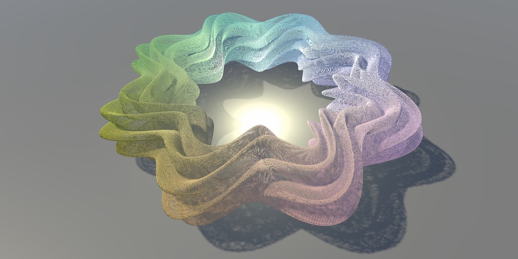
wanted to learn more about shader's and was able to come up with something simple to represent a water flow-like plane shown in the img. I was hoping to get some direction though on being able to allow objects, such as the sphere in the example, to affect the "water's animation". so something like the water sinking downward relative to the position of the sphere object, to simulate gravity for example. Any tips on nodes, layer overrides?, or how to make this work ?

Water/fluid simulation in realtime is one of the hardest topics in computer graphics. There are many tutorials and research papers of different levels of complexity that you can look up online.
One common way is to have a particle or rb simulation simulation to get physically close behaviour to a liquid, then use it's data in your water visuals shader.
Usually just passing in an array of vectors where objects are colliding when running through the vertex shader is the most straight forward approach, but not by any means the most optimal way considering usually you're dealing with larger bodies of water.
A better approach is some vector field / flow field in the format of a texture that you pass into your vertex shader
And with that data, for each vertex you sample the neighboring values inside of those texture and then grab some average from the weights to then modify that vert
is it possible to get vertex colors not interpolated in pixel stage in shader graph
If you modify the vertex output attributes. I think there's a semantic to prevent interpolation and instead pick the closest value
what do you mean by vertex output attributes
In hlsl you have a struct representing what the vertex shader is outputting. It's usually called VSOut or something like that. That's generally called vertex output attributes(I think). You'll need to modify that struct.
oh via code? not shader graph?
I guess "attributes" is not the correct word here. It's used for the vertex data inputted into the vertex shader.
Yeah, I don't think you have control over it in shader graph.
Actually, apparently you do have:
https://docs.unity3d.com/Packages/com.unity.shadergraph@13.1/manual/Custom-Interpolators.html
Though, I'm not sure if you can specify whether to interpolate them or not.
From reading the docs a bit, it doesn't seem like you can change the interpolation method in shader graph.
im still stuck on this shader graph variable "bug"
okay found how to make it working, had to use IMaterialModifier, SetMaterialDirty and GetModifiedMaterial
do anyone have a good pointer to where i can read up on the URP hlsl libraries or knows what im doing wrong? i am trying to figure out how to write my own lit sprite shader in hlsl but im facing a issue with Sliced Textures, when i flip them they become invisible.
flip as in rotate the mesh? is this just backface culling? Changing the draw side to back or both should fix that.
when i flip x in the sprite renderer it becomes invisible. could it be just that it flips the mesh? 👀
you can check the otherside in the scene view and see! if you see nothing, enable shaded wireframe and verify the mesh exists
yay Stuff is showing up again properly!

now i can global shader parameter the palette swap 😄
HDR isn't working in my URP template
curious
for unlit that is
in the unlit shader graph , emission is greyed out, is this a change
Emission is unused in the Unlit output, should Add to Base Color instead
could i replicate this shader on unity? it's from blender, i want to create a toon shader that supports vertex colors

"Shader to RGB" is technically possible, but perhaps not as common method to create toon shading as posterizing or ramping the incoming light in the shader before it's applied to color
Blender doesn't let you do that so the node is practically the only way to do toon shading
How can I access the full world-space bounds of a mesh (i.e., the bounding box, including position, rotation, and scale) directly within a shader?
Built in
help, im new to shaders, I deleted the library foulder off of my project, and when I open my project suddently it doesnt know what a shader is anymore, all my graphs doesnt work and unity doesnt even know how to open those graphs, urp seems installed in the package manager and so is shadergraph and all idk whats going on,
also I remember doing that already being fine but im not sure
Start from looking at compile errors
Does anyone know why is it pink for me?

I want to make reflective material but its just pink
If you're using URP (universal rendering pipeline) you should be using an URP shader. URP/Lit, probably
But how to make it reflective tho
Increase smoothness.
Might be best to give this a read so you understand how physically based materials work:
https://marmoset.co/posts/physically-based-rendering-and-you-can-too/

We cover the basics of art content creation, some of the reasoning behind various PBR standards (without getting too technical), and squash some common misconceptions.
URP Lit and Complex Lit are the best picks for you. Try them after reading the article above 🙂
(Simple lit also exists for lower end platforms)
https://docs.unity3d.com/Packages/com.unity.render-pipelines.universal@14.0/manual/lit-shader.html
https://docs.unity3d.com/Packages/com.unity.render-pipelines.universal@14.0/manual/shader-complex-lit.html
ok it works thanks
idk if any of it helps,
I would really apretiate if anyone could help
I have no idea why unity wont recognize my shader graphs anymore I dont understant


It literally tells you that it's file reading or writing issue.
Try moving your project out of the users directory, ideally somewhere near the root of a disk. If the errors persist, try deleting the library folder
ok
it worked thank you! 🥺🥺🥺
my fullscreen shader graph is only affecting half of the screen (one triangle?) I'm using the HD scene color node with some noisy UVs


if any one has done texture atlas for a 2D grid where tiles can have different textures.. is it more performant to update a grid map to read what texture is at a given x:y or is it more performant to encode that data into the extra uv channels in the mesh object ?
Hi. I'm using 3D lights on 2d sprite renderer
The resulting lit part is not so... pixel-y. Is there a way for the lit part to be applied on whole pixels (of the texture) instead of the fragment screen pixel?

I found a reddit post that has a few comments with some good suggestions:
https://www.reddit.com/r/Unity3D/comments/a866sg/how_can_i_achieve_pixelated_lighting/
I think for this the best result will be by making a custom shader where you modify the lighting calculation.
guys, I've created outline for my 2d monsters.
- is there any way to show the outline only when it's blocked by something?
- can I render this specific nodes for
outlineLayer, so other camera will render it?


Hey everyone.
Could someone point me in the right direction to making vertices of one object 'bend around' the geometry of another through shaders?
The particular case-use would be... vertices of the water plane dipping under the hull of the boat wherever the boat moves across this plane. It's an approach that was used for AC: Black Flag as pointed out in here: https://www.youtube.com/watch?v=euQw6IYe6Nw
I wonder if anyone ever did something similar or came across an approach like this, not necessarily revolving around ships and water? Or maybe someone has at least a vague idea on how this could be implemented in Unity?

More Game Art Tricks: http://simonschreibt.de/game-art-tricks/
Article to this Video: https://simonschreibt.de/gat/black-flag-waterplane/
Great DepthBuffer-Article: https://fgiesen.wordpress.com/2011/07/08/a-trip-through-the-graphics-pipeline-2011-part-7/
Music:
“Team up the crew”, “Leave this town"
by Toxz Beats (www.toxz.de)
“Misty...
how can i use a compute buffer in shader graph if at all as an array for data instead of using a texture
@toxic peakthe water doesnt dip below the boat - the volume of the boat masks the water out using stencil shader
I think they used stencil approach for the smaller boats, but for the bigger - they curve the mesh, or at the very least it looks that way. Guy on the video thinks so too.
Masking the water with stencils or scene depth comparison does work, but both have their own gimmicks and limitations when the character has to go 'below' the waterline when entering the hull. It's a whole another thing. I was specifically interested in displacing vertices around a specific shape and if that can be reasonably done with shaders.
i can guarentee they dont curve the water around the boat for the black flags and they also dont in sea of thieves
ive seen their tech presentations on it - they just mask it out with volume
oh, huh. okay then
mask is very performant solution 🙂
@toxic peakalthough this is unreal engine this is what volume masking can do: https://youtu.be/-py91uoMVNo?t=46 same technique applies in any engine
myeah, I think most of the volume stuff in Unity is reserved for HDRP though
nah you can use volume stencil in urp too
Ive kinda have a solution already that uses sdf fields... but what do you mean by 'volume stencil'
its a standard shader technique its not reserved for hdrp unless you are using unity's water api which is only for hdrp anyway
https://www.youtube.com/watch?v=z2uFaBoYhaY heres a unity explanation

How to Use Depth Mask to Hide Water in Boats in Unity
1:06 to skip Intro
5:14 to jump to Blender Instructions
Have you been trying to figure out how to put your boats in the water, but not let the water seep in? Then this tutorial is for you!
Here is the Unity Wiki on the depth mask:
http://wiki.unity3d.com/index.php/DepthMask
Last I checked...
as far as I was able to figure out - stencils are kinda.... uuuh... they are reliant on how your camera is placed and whatnot
yeah exactly that
I know that video
it works as long as your camera is above the masking shape
but what if you have a big boat and you have to go inside of it, and dip below and above the sloshing waterline?
well... there is a solution for that, you kinda 'coat' the insides of a boat in stencil mask... I've seen a guy do that for a multiplayer ship game. He inverted the normals of the masking stencil mesh
but if you have complex objects and different shaders working inside of the boat... I dunno. It feels to me like it can introduce some troubles down the line
at least that's what I fear
well if you want an alternative. keep the water plane in fixed place around the boat so when you move the boat - the water plane moves with you... and just remove the vertices inside the boat's volume
that could also work
but what if your boat turns and bobs in different directions? or if it can flip over? its sideways profile will not match the hole in the water 🤔
the water plane turns too you just have to turn the ocean animation with a transform matrix rather than the physical mesh
so once you know the waves you then apply a matrix to rotate it all
so if you turn your boat and water plane left the wave animation data needs to rotate right so it stays in place in world space
no I mean, uuuh... if the boat turns to the side like this

otherwise the waves turn with you which looks odd
capsizing or whats it called
oh like a sinking ship
ye ye
and you're inside it
ye
if you in ship can you see outside of the ship such as windows?
if no windows you could just turn the water effects off
true that, hmm
i think stencil is the best approach though
when in ship any pixel that is in the ship's volume you discard the water pixel
that's the thing with stencil - it works depending on how you view these volumes
so it won't cut the pixels out if you're inside of the volume
you have to look at it from outside for it to work
i think you can if you allow rendering both faces of the volume mesh
since by default it only applies the front facing faces
yeah thats true, in that case it will compare stencil against the thing even from inside
yeah give it a try and see how it goes
oh I already did! it does work
Ive had a screenshot somewhere, hold on

the thing is, Ive used a setup that uuuh... it doesnt use a stencil material, but it uses stencil LAYER with Renderer Features. The thing is - if any object inside of the boat obscures the stencil mesh - water will render above this object, so you have to put all of these objects on the stencil layer

but the setup Ive used was kinda... funky. it used a specific layer order or something. I dont understand it fully, but it may mess with transparent materials if they are put inside of the boat
or maybe somewhere down the line I would use some kind of an effect that triggers inside of the boat - and the water will be drawn over it, and I wouldnt be able to do anything about it
but maybe that won't happen? I dunno
im not sure havent gone that detailed into it
Hi all. It seems the Sprite slot in SpriteRenderer is detected as _MainTex in shader
Can i have more of these special slots/property name?
But SpriteRenderer is sealed class too..
fixed, I had to use the drawprocedural pass instead of blit
anyone got idea how can i achieve first look here? mine looks lowkey garbage


the lighting i mean not the mesh
There's two main sources of light in the reference image: the direct light from the pink sunset and the blue-ish ambient light. In reality, there is a lot of indirect lighting bouncing off the snow, which would normally be difficult to replicate without baked or real-time global illumination.
But because the sky is cloudy and one uniform color, and the entire scene is covered in snow, the overall ambient lighting ends up being very uniform and can be replicated with a simple single color ambient probe.
The main part where the light is not uniform is the occlusion in and under the tress. Screen space ambient occlusion might be enough for you. Sky occlusion would be a step further, and that can be done with APV.
nvm it had nothing to do with shaders, i was able to get it looking decent with some exr + color + indirect gi tinkering

exactly.
i figured it out to be like that lol
what do you mean sky occlusion/apv ?
that is not already default behavior in gi ?
Yes, if you're baking the lighting, you will get sky occlusion. APV's sky occlusion is for if you want to be able to change the lighting while still maintaining correct sky occlusion.
@low lichen unrelated but have you got an idea how can we do something like this ? the bloomy snowy atmosphere? i could get a billboard for the cathedral with emission. but how to get that soft bloomy feel ?

This is essentially the same principle as volumetric fog. So, however you'd achieve that is how you'd get this look. There are generally two approaches for volumetric fog, analytical and voxel. Analytical is simpler, faster, but can't produce arbitrary shapes, only mathematical shapes like spheres, cones, etc. Voxel based fog is heavier, both in memory and processing and often needs to be downsampled, denoised, but can support arbitrary shapes and shadows.
that looks like an overkill sadly
I've used this asset before with URP. I can recommend it, but it's pricey.
https://assetstore.unity.com/packages/vfx/shaders/fullscreen-camera-effects/analytical-volumetric-lighting-urp-performant-raytraced-volumetr-266586
Unity doesn't have any analytical volumetric fog built-in. HDRP's local volumetric fog is voxel based.

Add depth to your project with Analytical Volumetric Lighting [URP] - Performant Raytraced Volumetric Lights asset from Akidevcat. Find this & more VFX options on the Unity Asset Store.
But because it's analytical, you're limited to basic shapes like point lights, spot lights, rectangular area lights. To mimic the reference image, you'd need to manually author a point or spot light to best resemble the shape of the building.
im using BIRP also
it looks good though
afaik u cannot use standard birp materials in urp
In addition to a lot of indirect bounce lighting, snow exhibits a lot of light transmission / translucence which is devilishly difficult to do in realtime graphics
For that you'd need some type of SSS or at least a smoother light ramp for directional attenuation
Not even ray tracing can really handle snow because it scatters light too much to denoise
yeah, ik. SSS is overkill for little income, a smoother ramping is probably a good idea
a good SSS will fix the ramping irl, but can't get good one in realtime
for this maybe i just pre bake the whole sky dome
idk
not big fan of pre baking
Please forgive me if I explain this badly.
I'm using Triplanar mapping to build up a terrain shader (layers based on height and 'steepness'
But I'm also using a 'floating origin' system because I want my map to be big, but I'm concerned that when I hit the threshold to move everything back to the origin the triplanar mapping will have a noticeable 'jolt' as it does.
Is there a way to give the triplanar a 'fixed' point from where to reference where it should be mapping from so that it always stays 'locked' to the object it's assigned to?
lol. Typical. Never mind, I just figured it out. Position Node (Object Space) into Absolute World Position input of the Triplanar Node
Hey there I'm trying to set up a retro dither full screen shader


This tutorial will show you how to make a retro-inspired dither effect in Unity URP using the shader graph.
#unity #unity3d #gamedev #shadergraph #urp
Following this tutorial but even after adding a renderer and adding the material in my URP_Asset Renderer which is my default renderer There's no change at all


I have tried multiple different videos and none have worked the way I wanted (one of them which applied based on if an object was on a specific layer but it just didnt work while the rest only affected 1 material, however to say that). Tried to make myself, but didn't work either. How would I go about making an outline shader that works with a Mesh Renderer that has more than 1 material?
All of a sudden I've been getting this erorr and I have no idea what could be causing it:
UnityEditor.Graphing.GraphObject:OnBeforeSerialize ()```
Does anyone know how to fix this?I have written a mini guide for this in this comment here: https://www.reddit.com/r/Unity3D/comments/1izolat/comment/mf4vngc/?context=3 which does not require any code other than the shader

Reddit
Explore this conversation and more from the Unity3D community
I found a partial fix for the contrasting color artifacting I had on my distortion + blur shader effect by setting the rendering path from "Deferred" to "Forward", however this does not solve the issue where I get upside down occluding geometry ghosting overlapping my shader. I repeatedly tried a whole slew of fixes including ChatGPT suggested fixes (+20 give or take), but none so far have helped getting rid of this ghosting. something has to be off in the Z depth buffer I have to assume but I can't pinpoint where the issue exactly sits. (Ztest has to be set to Lequal and shader render que has to be 3000 or higher). anyone has experience wit this? (project uses Unity 2022.3.29f1, built in renderer)


this shader is sooo close to being perfect, but the ghosting ruins it
Use the frame debugger or native graphics debugging tools to see where this ghosting is originating from and possibly figuring out a solution
never mind, I got it! there was a slew of code that handled ZDepth falloff and soft particle factor that caused these artifacts
I eliminated these parts of the code and that god rid of the ghosting altogether so I'd say the issue is truly fixed now
Is there anyone here who knows about Stencil Buffer and could help me, please?
What's the math for dissolving one texture by another in a shader?
Sample the other texture and use that value as the alpha
Do some remapping if it needs to be animated
Hi. I'm trying to use this, but this uses 2D lights to work. In its shadergraph, the material is using Sprite Custom Lit
Is there a way to make this work with 3D lights instead?
https://github.com/NullTale/LutLight2D
And btw, in my case of making 2.5D (environment is 3D, characters are sprite renderers), is it possible/feasible to use both 2D and 3D lights together?
The error of the shadergraph shader is..
Shader error in 'Shader Graphs/LutLight': undeclared identifier 'error' at Assets/Packages/www.nulltale.lutlight2d@ce3b725afa/Runtime/Shaders/LutLight.shadergraph(753) (on d3d11)
And when viewing generated shader, there is literally a line like this
float4 _SampleTexture2D_374f3fae7d46483aa45b887bac71de36_RGBA_0_Vector4 = SAMPLE_TEXTURE2D(error.tex, error.samplerstate, error.GetTransformedUV(_Pixelated_4415aa866542411eb15650a74b21e942_Out_0_Vector2) );``` So yea, a var called error that's not declared yet. What is this and how to fix it?Thanks. One of the guides also tried it with layers but it worked weirdly, but this one works great.
Hello Everyone.
Can someone please link me a tutorial or a source on how to apply a shader or material to the white part and not the black border on a sprite?

someone got an idea why the normal maps in unity look bad. i noticed this for almost every model i try. they don't look "dark enough" (or is it not normal problem?) here's an example for a terrain in Gaea vs in Unity


The left one just doesn't seem to be lit.
ik. but it is lit + it has normal.
Well, I only see albedo. No shadows or lighting at all. Normals don't do anything in such a scenario

No.
Now I do see a bit of shadows, but it's very weak. It's as if there's not directional light. Just ambient occlusion. I also do see bumps on the snow, but this might as well be geometry and not normals.
Overall, I think the comparison environment or settings are just not 1 to 1.
Well neither i am
Is that left screenshot made in unity as well(just with a different shader)?
so you can pass these type of questions. its a lit shader with normal and all. and no these bumps are not geomry
I'm not saying it's not. I'm asking wether there's a light source in that env.
the bumps appear more because of less ambient light contribution
also ao maps cannot render such details for terrains (large scale)
neither can geometry.
yes there's, you literally cannot have bumps without a light source
As dlich is saying if the lighting conditions and environment aren't the same or at least similar, the results won't be comparable
You didn't confirm that exactly
You can with gi, indirect lighting. The left screenshot seems to not have a direct light source
no, they are not the same, im asking why
That doesn't really tell us anything
It's not about realtime or not. It's about the render engine and it's settings.
Are they both in unity or not?
both in unity yes, but the right one i do not own it (gaea)
And GI can be realtime.
Are you comparing both in the same scene/environment?
Can you take a screenshot of both terrains side to side?
no i do not own the right one (it's a software based on unity)
it just makes heightmaps
Doesn't matter what type of lighting it is as long as the lighting is not different between them when you compare
The image on the left is also missing specular which as mentioned suggests you're missing a main light
the shader is non specular
You cannot verify whether your normal maps are working right or not if you don't have an objective testing environment
so you suggest adding specularity will make it look alike ? i doubt. it can be a step
the normals are working
they just do not look good (washed, barely seen, as you can see)
unless i reduce ambient light contribution
which dulls the scene
Most types of ambient light illuminate surfaces regardless of normal direction, so effectively washing out the relative effect of normal maps
yes ik, thats why i reduced it to see
the question is how do i get it to look like the one on the right
or what makes the right one look good ?
You'll need to learn the lighting and environment settings uses in the right screenshot
1 big thing is probably not having a directional light source.
If the material properties like specular are different, the lights and lighting environment are different, and the normal maps could have problems that's a bit too many variables to just eyeball
so what do you suggest?
i renderdoc it ?
specularity definetly makes it better, but still too far.


If you don't have access to the right screenshot environment, that sounds like an option.
Seems to have a shadowcasting directional light at a steep angle, at least
We can't really provide a better response without more info.
But at the least you can add a similar directional light(something we've been saying many times over).
minimal effect
Can you reproduce the same shadows we see on the right screenshot and take a screenshot?
sure, here the same light direction. my unity shadows are just not hard enough like it


How do i make it so the spriterenderer's color be the same as one of my shadergraph's variables? I tried right-click → Set as Main Color but it doesnt work, it just multiplies the final output. Also, can this be done with the Flip attribute?
This doesn't look the same. Also the light intensity looks to be weaker.
i tried stronger, just minimal effect
sorry wrong rotation of the terrain, flipped, but same thing


Can you share a screenshot of what it looks like now?
Shadows are only as dark as the ambient lighting
yes of course
i even thought about modifying the lighting func, to amplify shadow contribution
Instead of dimming down the ambient lighting? Why would that be a better option
to not dull the whole scene
Are not trying to reproduce the right screenshot?
yes
i am
ambient light changes both shadowed and non shadowed parts. i thought maybe i can amplify it (reduce) for shadowed parts only or sth
That doesn't really make sense to me
Increasing ambient light would "dull" the scene by decreasing contrast between light and shadow especially with the normal map
When you decrease ambient lighting and increase directional light to compensate, the contrast increases
yep makes sense 👍
I just noticed the light source here. Assuming that's it's real angle and we don't see long shadows, I'd assume there's missing geometry.
Possibly the right screenshot uses vertex displacement to create geometry from height map.
And it also feels like it might be using some form of GI. Whether baked or real time.
Possibly the right screenshot uses vertex displacement to create geometry from height map
this makes no sense ? heightmap already "displaces vertices" (by literally creating a mesh)
It depends on the context. If it's a unity terrain, then yes, there's a hightmap that creates geometry. If it's a regular mesh, the shader could additionally displace vertices to add more details.
why would it do that when it can just bake it into heightmap, if we are talking about performance by distance tesselation it makes no sense here bc the terrain is looked up from afar
I'm simply basing off the look/shape of the shadows.
Can you recreate shadows similar to the ones on this screenshot or not?
#archived-shaders message
of course but maybe we continue later on i gotta sleep for work tomorrow. (thanks already)
I'm having a really weird issue when using material property blocks. Previously I was modifying a shader's properties directly, but I wanted to change this to modify the spriterenderer's mpb instead. I'm using the exact same values, I literally just replaced the shader's name with the mpb's name and applied the mpb, but the result is totally messed up. Do you guys have a clue as to what might be going on, before I go into details?
The shader is done in shader graph
I'm making a water shader, and I want it to render after opaques (so the scene depth texture is available for the depth node) but before transparents.
A render queue value of 2500 doesn't work wih the Scene Depth node, but 2501 does.
Any issue with using 2501?
"Height" is ambiguous
Usually it refers to parallax mapping, parallax occlusion mapping, vertex displacement or tessellated vertex displacement
I think HDRP might be capable of all four but you have to choose the type
URP only does parallax mapping, POM if you grab an official sample for it, displacement if you make a shader for it
No tessellation unless you implement it from scratch
good morning
tesselation, parallax, .. seems beyond useless
here
its either a frag shader problem or a lighting problem or both
upon searching i found this hdrp vs birp image which kind of moves us towards the desired look. if you see, for some reason hdrp seem to have darker shadow/normal highlights. you got any idea why? or just lighting model?

LWRP was an ancient version of URP, not BiRP, so the commparison is outdated and not indicative of anything
HDRP has also come quite some ways since those days
I'm still a bit fuzzy on what the actual problem is
Or the goal, moreover
sure but you didn't explain why
get the left img to look like right one
basically "what to tinker"
But why exactly
What's so special about the image on the right
nothing. it's just that i cannot reproduce it
currently
well ultimate goal is knowledge if you wanna go far
for example here i still do not know why such big difference
That's good to know the focus isn't necessarily just to get something identical but to understand
The difference between these examples is mainly indirect shadows, which could be SSAO or baked lighting
And also the intensity of reflected light on surfaces which could be difference of gamma vs linear color space, or tonemapping profile / HDR configuration otherwise
i tried it before birp vs hdrp, the difference is definetly not ao. also no baking used jn both, also birp was in linear as well
The example is a bit counterintuitive to me because HDR tonemapping and linear color space tend to flatten the colors and brightness range of the image, purposefully so post processing has more headroom to work with to bring contrast back up without losing color information, but in this case the LWRP which is less likely to have HDR or linear color space, also has flatter colors
Neither appearance is more "correct" in my opinion
i know in those images its lwrp vs hdrp, but its very close if not identical to birp vs hdrp
i see what you mean, but the question is why is it darker shadows
look at the hill from afar in the fog
Well the difference between two different URP scenes could be bigger than the difference of BiRP and URP in some other scene, so I don't think we can confidently say that when we don't know the exact configuration
When URP was called LWRP, BiRP was much closer to HDRP than LWRP in rendering features
Main difference is that BiRP always used linear light distance attenuation / falloff, while URP and HDRP always used inverse square root falloff which is physically accurate
ok so anyway. the difference in shadows cannot be tonemapping nor space right because shadows are too "selective" / coordinated to be that. i suppose its a shading difference?
HDRP image having AO is probably the one thing I'm really confident about here
It could even be SSAO rendering in front of the fog, really exaggerating the shadows on the distant rock
Which it isn't supposed to do
look at the small details. these are normals not geometry
Iirc LWRP only supported linear fog, while HDRP defaulted to quadratic fog, also
What of it?
There's enough both for the shadows to be AO just from geometry
HDRP probably can use fragment normals with SSAO but not totally sure if it does
i mean look at the small cracks on rocks, these are not geometry and they appear darker, so it cant be ao, they are probably normals
hmm never heard about this
but yep i think its a shader difference ultimately rather than lighting
There are normal maps in both images
The cracks are relatively as dark as the surrounding rock in both comparisons, but the overall shadows are darker in corners with AO present
The material may also have an AO map, in addition to screenspace or baked AO
idk, the ao thing doesnt cut it for me
95% of the differences I see are lighting and post processing
I think the different is in specularity, the HDRP has more specular than the LWRP, its mostly noticeable in the far mountain
That's also affected by tonemapping, same as darkness of shadows
But for all we know the material properties are different
wym? could you explain a bit more
I'm not sure, I'm just saying what I see
HDRP basically has to have tonemapping, and because of that it has to have post processing because tonemapping to bring the contrast back because tonemapping isn't meant to be used alone
At that step the author will determine the exposure, and the visual look with overrides like shadows, midtones and highlights
Which all affect appearance of light and shadow
LWRP was more of a wysiwyg thing
hmm.. interesting. but would tone mapping explain the specularity in the fog?
if feel like no?
but maybe it affects shadows
It partially affects both
But in this case there are unknown variables
I don't know if the comparison is meant to show off the render pipelines as closely as possible, or if it's showing just the assets and the RPs are incidentally there
If the material properties were tweaked, or if LWRP even had quite the same lit shader as URP does now
so to sum up, in birp, can we somehow get a closer look to that
adding specularity into he shader was a big step, but what else
I think you can get a closer look to that in BiRP, and even moreso in modern URP, and probably even in that ancient LWRP if the setup was tweaked with more care
Definitely ambient occlusion, screenspace or baked whichever works better
Sharper visual contrast with post processing, using curve, shadows/midtones/highlights, whichever works likewise
Could increase normal strength if you're into tweaking material properties
Though with PBR materials you shouldn't go wild with them to keep them physically accurate
If the material comes with AO maps, use them
already do most of these. except baking, im not fan of. also i use a 3d lut authored from blender, unsure if i wanna replace it by my own tone mapping
i tried different aos too horizon, msao, etc
the thing with terrains is you. cannot bake aos because they are huge
even 4k textures are useless
Did we confirm that both screenshota were even taken in unity and the same render pipeline?
we were talking about these
It seems a bit of a pointless excercise to worry about matching a result pixel perfectly when we don't have the same assets, same RP or even the scene to verify with
If you're using URP or HDRP and good PBR materials, you shouldn't be worrying about the shader side of things
But rather focusing on learning what tools you have to work with when it comes to lighting and post processing
If you don't know how to use them well and start modifying the shaders or materials that are already physically accurate, you'll end up in a situation that you have no means to fix or troubleshoot
Hdrp might have real time or baked global illumination enabled making lighting and shadows way more realistic than non baked urp and birp.
As long as you learn to use those tools, getting any kind of result you want becomes feasible and even easy
And then you might realise that the examples you were using before weren't really exemplary after all
The example could very well have baked lightmaps, since it's a very small area
But to my eye they look like screenspace, and if they were baked LWRP would likely have them too because it always supported baked AO, but not SSAO
Anyway, get scenes that you can actually poke at
Unity has many templates and samples for HDRP and URP both
With photorealistic PBR getting a specific look isn't as important as using all the tools, within intended paramaters
tools include what? (baking out) light rigging, material, shader, tonemapping/lutmapping and ss effects
is there more?
maybe volumetrics. useless here
For starters, understand what contributes to the lights/shadows and final image in your scenario.
It is possible to use Stencil Buffer in Shader Graphs? Using HDRP
In unlit or lit materials.
I don't think so. At least it wasn't possible a few years ago.
does unity unloads textures from gpu memory when all instances of a materials are inactive. or not. regardless of the answer where can i find info like this
i suppose not since there's no buffering right? if so, how can i tell unity to unload a material
I don't think it's enabled by default, but the feature is there.
https://docs.unity3d.com/6000.0/Documentation/Manual/TextureStreaming-introduction.html
Howdy! What's the best way to make this floor look wet, I assume with shaders?

Also wondering if there is like just such thing as using a transparent 'wet' texture to overlay?
The 'wetness' doesn't need to move
@kind juniper @grizzled bolt interesting that tinkering with the specularity color + intensity and normal map intensity made the normals actually appear blacker. much more realistic. (even more realistic than the image on the right). but looking at the terrain from afar still looks like it's not even lit/so bad. i'm kinda confused

at this point it became a game of trying and failing till i hit the result, which isn't what i want tbh, im not learning much. like, apparently specularity affects normals somehow ?

The simplest way would be to increase smoothness of the texture if you want the whole floor to be wet
If you want puddles, ye, you could make a shader where you can paint the wetness (i.e. smoothbess) onto it
A decal with the correct pbr material could do the trick, or using a material with such details already in it.
PBR covers most bases for shading natural things
Normals can't be "black" they don't hold any color information. Just direction.
As for your scene being too bright, it's likely because of the ambient color.
I discovered another way on how artifacting is generated; adding light sources (a basic point light in this case) even when in forward rendering path does generate this artifacting. I did consult ChatGPT for possible fixes, one of which supposedly would help by rendering the shader "premultiplied alpha" which does get rid of the contrasting artifact, however, this causes another artifact where there particles get overlapping black borders. ChatGPT thinks these are artifacts caused by a alpha texture masks that have color values other than white (such as slight tinges of gray) however I've confirmed multiple times that the masking texture uses only white pixeles and opacity falloff for the alpha channel. anyone else ever had this issue with transparent unlit distortion shaders? you'd think with this being unlit, it would not be affected by lighting, yet it is here, and usually more affected the more intense and closer the lightsource is to the particle effect (p.s. yes this is a X49 night raven from ace combat 3/infinity, but I entirely modeled this aircraft myself from scratch)


this kinda sucks because the shader is near perfect as is right now, but that one little persisting artifacting issue is what keeps it from being the ideal and ready to use in future projects.
As I mentioned earlier, you'd need to use debugging tools to see where this is originating and why. The only thing I can assume is that invalid values are being written or read somewhere.
Hey all,
So, still working on my terrain shader and making great progress and having a lot of fun, but I'm hitting a bit of a snag.
Is it at all possible, in Shader Graph to use Arrays for input values?
For example, I have a bunch of 'material rules' with a lot of 'repeating' textures with different rulesets (See attached file (formatted xml-ish for ease of reading) and was wondering if I could use arrays to build up the material so that it could be a bit more dynamic and remove the need to have a ridiculous amount of node trees etc.
Just realised I forgot this. lol.
Normals affect specular lighting, not vice versa
Like I said if you want to learn realistic rendering, tweaking material properties until it "looks right" is not the way to go especially when you don't understand PBR, lighting or post processing properly yet
You should use PBR materials that you can trust already have the correct properties and tweak everything else besides the materials
Shadow darkness comes from dimming ambient light and implementing AO, but it feels you've rejected both of those points arbitrarily
Okay, so I've found @regal stag 's Custom Node array stuff, and I think I've got my head around it.
In my head I would need float arrays for the following (I guess these could be Vector2s instead)
heightMin
heightMax
latitudeMin
latitudeMax
slopeMin
slopeMax
And inputs and outputs to match (matched by order that the floats and outs are defined?)
float _heightMin[10];
float _heightMax[10];
float _latitudeMin[10];
float _latitudeMax[10];
float _slopeMin[10];
float _slopeMax[10];

void ExampleFunction_float(out float HeightMin, out float HeightMax, out float LatitudeMin, out float LatitudeMax, out float SlopeMin, out float SlopeMax){

   for (int i=0;i<10;i++){

    HeightMin += _heightMin[10];
    HeightMax += _heightMax[10];
    LatitudeMin += _latitudeMin[10];
    LatitudeMax += _latitudeMax[10];
    SlopeMin += _slopeMin[10];
    SlopeMax += _slopeMax[10];
  }
}
Unless I'm missing something reeeeeeally obvious, and as long as I don't mess anything up 'after' this in the node 'chain' this should paint the selected texture in all of the places defined in this custom node?
Obviously the 10's in the loop need to be changed to i, cause I'm a spanner. lol.
After a bit of brain hurtiness, here's the new (and hopfully final) custom node code.
float2 _heights[10];
float2 _latitudes[10];
float2 _slopes[10];

void TexturePainting_Vector4(out float2 Heights, out float2 Latitudes, out float2 Slopes)
{
    for (int i = 0; i < 10; i++)
    {
        Heights += (_heights[i]);
        Latitudes += (_latitudes[i]);
        Slopes += (_slopes[i]);
    }
}
I realised that I don't need inputs on the node as the c# fills the arrays directly.
Yet more changes, cause I'm an idiot. lol.
float4 _heights[10];
float4 _latitudes[10];
float4 _slopes[10];

void TexturePainting_Vector4(out float2 Heights, out float2 Latitudes, out float2 Slopes)
{
    for (int i = 0; i < 10; i++)
    {
        Heights += (_heights[i]);
        Latitudes += (_latitudes[i]);
        Slopes += (_slopes[i]);
    }
}
Still not sure this is right tbh.
Uuh okay, now I'm confused 😕

float4 _heights[10];
float4 _latitudes[10];
float4 _slopes[10];

void TexturePainting_Vector4_float(out float4 Heights, out float4 Latitudes, out float4 Slopes)
{
    for (int i = 0; i < 10; i++)
    {
        Heights += (_heights[i]);
        Latitudes += (_latitudes[i]);
        Slopes += (_slopes[i]);
    }
}
Oh wait, I think I know why. Cause I'm not running the c# lol.
Dangit, nope, tis all broken and I don't understand why.
@regal stag sorry for the ping, but can you provide any insight please? 😦
Might need Heights = 0; etc before the loop to initialize the variables
And to clarify, the function body uses += to sum the contents of the array, only to provide an example and likely doesn't match what you want to achieve here.
I don't think I understand the intended use-case completely, but if there's min/max values you'd probably want to pass inputs into the function and handle remapping in the code itself to produce a mask for each texture? Might even need to sample the textures in the function?
Aaah okay, I get ya.
Yeah basically I'm looking to try and get the textures to only appear on my terrain between those min/max values. I can do it for a single texture and single set of values, but I'm trying to figure out a way to do it so that I don't end up with hundreds of nodes etc. and so that it can be a little more 'dynamic' if that makes sense?
loop (foreach in array?)
{
  if(minHeight > a & maxHeight < b) & (minLat < c & maxLat > d) & (minSlope < e & maxSlope > f)
  {
    this will create Texture1 and add to Texture0
  }
  Move to next Texture
}
Not sure if this makes sense, but ludicrously simple pseudo for what I'm thinking
Thinking about it, based on what you said about the +=, Maybe using the custom node/code to create the 'composite' (dunno if that's the right term) texture to then output, would probably be easier in the long run?
can someone please explain how to solve black bleeding into edges?
https://discussions.unity.com/t/announcing-the-shader-graph-ugui-shaders-sample/1602836/37
Im a noob shader graph user, and stuck here
It looks like you're using the graph to create the alpha? If this is the case, then you will always have edge pixels, in the graph settings try changing the blending mode (see image).
Failing that, remake the image and save it with an alpha channel, and set the import settings of the image to 'alpha is transparent'

Ooooooookay, so I'm having another brain fart.
trying to setup the 'basic' parts of the terrain shader properly, and having a major brain block (long ass day lol.)
Image 1 is the 'donor' graph and image 2 is my current graph. The major change is the facility to define the minheight and maxheight values where the texture should be applied, instead of just applying the texture everywhere above the minheight. Problem is I can't for the life of me figure out what I need to plug into the SmoothStep node after the change.


I give up, this is driving me insane. 😦
Okay, seriously, how hard can it be to use world height and min/max values to get something like this?

OH!! I think I've done it. lol. (sorry for all the messages, been one of those days)

HAH!
Okay, so I've gotten two of the important bits sorted and working independently.
Now just need to figure out how to blend them together so they're a single mask.
And then figure out the whole latitude part.

hey, why is the texture not tiling? i've tried it with png and jpg, the only texture that tiles properly is unity's built-in default particle-_-
how do i fix it?

Change the wrap mode on the texture asset to Repeat (rather than Clamp)
ty!!!
Hey. Anyone here familiar with the Unity Shaders Bible? I'm wondering how updated it is and if it leverages URP features in Unity 6.
I just checked it out and… maybe?
It does go into URP but IMO it’s too focused on Shaderlab to be relevant. Writing HLSL for URP is still very impractical
So… it does have the information you need, but at least a third of the book would be impractical to use with URP.
https://docs.unity3d.com/ScriptReference/Material.SetTexture.html
what does the name param refer to in here ? Value is the actual texture ur setting right ? I think im getting confused on the difference between textures and shaders, since the link references:
"_MainTex" is the main diffuse texture. This can also be accessed via mainTexture property.
"_BumpMap" is the normal map.

is it a string value that we can override with any name we want or does it reference something specific like normal maps (_BumpMap)? What would "_Map" be ?
Unity! Hello I need to pass 18 different values per vertex so I tried to use uv channels but there are only 3 extra uv channels and two floats from uv0, so thats total 12+2 = 14
How can I do this?
Use GraphicsBuffer (ComputeBuffer)
Its the variable name of the texture. This is usually different to the display name. The description is telling you how the main diffuse texture is usually _MainTex. Shader graph example:

can I still use unity's lighting?
It depends on your shader. But in general - yes, you can.
anyway I can still use shader-graph? I feel like completely dropping shader graph for the sake of increased vertex data daunting because I find graphical programming very practical when it comes to graphical shader programming
Yes, you can use shader graph. Although some handwritten custom nodes required to access provided GraphicsBuffer data.

Hey @regal stag I was thinking about the loop Custom Node again today while doing actual work and something occurred to me.
I'm inputting for example,
_heights[10]
and outputting
Heights
Would the operation inside the loop not be as simple as
Heights = _heights[i] ?
And that would spit out the value at _heights[i] or am I oversimplifying it and missing something?
_heights[i] would indeed index the array at each iteration of the loop, but after that loop runs Heights would just be set to the last value in the array, and that's what would be output in the graph.
Would be the same as doing no loop and Heights = _heights[9];
Aaaah I get ya. Hmm. This stuff is Haaaard. lol.
how can i pass a texture to my shader graph so when i sample it - i get the true value i set? i have a grid map where each pixel x:y holds an integer which represents an index in a texure array but i have suspicions its not keeping the true integer values im setting
Is there a way to have a particle system inherit the color/alpha from a given texture?
I swear this was possible.
Built in, not through scripting.
Ah, it's in the shape module.
ah, this thing

What's the format of that texture?
GraphicsFormat.R16G16B16A16_UInt
i need int4 per pixel essentially
but i think in shader graph when i sample its giving me values between 0..1
Unit might get converted to floating point. Try using a float format instead.
how come theres no simple raw buffer option rather than textures
It's not as simple due to how graphics APIs and GPUs work. For raw data you usually use buffers.
yeh in computer shader i can just use structured buffer but i want to use one in shader graph so i can sample the value as its just an array of data not texture in the conventional sense
its a pain they dont support buffers in shader graph
It might be possible if you had full control of the shader.
They do with custom hlsl node
but unless im just on old version theres no way to have a structured buffer property so you can't set the buffer in c# land
Wdym?
I don't think any of that changed in newer versions.
if i want to add my buffer to my material it doesnt support a property of buffer so i dont understand how to set the buffer to my material

You have to bind it via C#.
yeh with material.SetBuffer right? but i need a property name but shader graph doesn't have buffer option ?
unless theres some weird way to do for buffers specifically
I think defining it in the custom hlsl node and using its name should work.
Anyways, I'd try the float format of a texture first. And if that still makes it a 0-1 range, you could do some math in the shader to get the index. For example, normalizedIndex * maxSize or something.
I think Particle System bounds calculations is broken if you use Sprite shape.
Hey, I'm using a Custom Render Feature for a screen space outline shader.
I'm using this: https://github.com/Robinseibold/Unity-URP-Outlines
It works fine in the editor, but when I build the project, something weird happens.
(I'll share photos/videos below.)
Any solutions?
GitHub
A custom renderer feature for screen space outlines - Robinseibold/Unity-URP-Outlines
this is how it should and looks in the editor
this is how it looks in the build
these are my setting to always render the outlined object in front of the outline itself

and this is the error I get when I build the game

it's like it hides everything but itself
how do i make the shader work in unity, i'm trying to create light instance

why is there only one
Does anyone know how to setup HLSL support for Visual Studio? The amount of the errors caused by my HLSL intellisense being completely lost is infuriating

It does recognize some of the primitive HLSL types such as float and half or keywords like struct or return because I have the HLSL tools extension installed already
but it breaks with anything Unity related
it doesn't recognize imports

You'll need to configure the includes path in the hlsl extension config.
Because there's nothing at that relative path.
Which is exactly what you need to setup. The path from which relative paths would be resolved.
Do I need to touch to the virtualDirectoryMappings? Or is it only for UE users
{
    "hlsl.preprocessorDefinitions": {},
    "hlsl.additionalIncludeDirectories": [".", ".\\Library\\PackageCache"]
```}
Something along these lines?thing is that the packages I have installed in my Unity project all have a trailing hash in their names, so the top level includes won't exactly match

scratch that, this addon works like a charm

GitHub
Create shadertoolsconfig.json for Unity project. Contribute to hecomi/HLSLToolsForVisualStudioConfigGenerator development by creating an account on GitHub.
That one yes. It's not just for ue.
Made a complete custom stylized shader for outlines, objects and skybox

Check if you added the shaders to always be included as mentioned in the readme (if using addressables, add them to a group).
That error implies the shader failed to compile for your target platform, is the default quality level set to what you are using in editor?
If you are modifying material parameters in code you need to reference the material through the MeshRenderer. This will give you a material instance. Otherwise the two objects are changing the original material and the second one will override the first.
I only have 1 quality level set to make sure. and yes I've added the shaders to always include

Then my next idea would be to use the frame debugger to verify if its the outline step that causes the issue
would it still show the issue if it only happens in build?
you can use it with dev builds
so make a dev build for the platform and connect the frame debugger, if its on a different device have it on the same network as the editor.
that's cool I didn't know that
the game crashes when I select the game window as the target
it's the same device I'm testing it on my pc
it happens just before ouline where it says clear (color)

is that clearing the frame buffer? Would explain it going black 🤔
Check if that happens also in editor
then it redraw the objcet I hovered on because I make it render after the outline to make the object display always in front of the outline

as I show here
it does

but it renders the objects again after that
can you record what actually happens? Id presume it would clear + draw the outline to some other buffer to then draw to the main frame buffer.
Id guess this step or the later draw steps are different in editor vs build
record it step by step in frame debugger?
Yea so we can see the left list and details (share x or windows snip (WIN SHIFT S) can do recording)
this is the editor just before it starts rendering the outline (the chair is an outlined object)
okay so it renders the chair to a different render target, then it uses a blit shader to add the result to the main output


This sounds right so do check what the dev build is doing
dev build
So that shows the blit fucked up and didnt correctly combine the result. if its shader graph see if you can check what its doing.


does it use a custom function node? otherwise it shouldnt have an error.
Or your unity version is too old.

hmm im not sure whats wrong here or why it would act differently in a build 🤔
me too. thank you for helping anyway
under different lighting


skybox is also custom and changes based on sun angle, stars fade in and out based on the night time
Wonderful
are the clouds meshes?
or are they procedurally generated
they are alpha clipped quads, same as the leaves and grass
didn't spend too much time on the clouds though, I'll make them recieve more volumetric looking shadows
Hello Im new to shaders and I need some help making a Shader/Material for Lava. I already have the textures I might need. I made a scene where lava will fill most of the empty area, like a lava lake.
What I am looking for:
To have Emision where the lava is, so it makes light.
Add movement to the lava using a Panner.
It would be nice if I could add some Trigonomerty (Sin, Cos, etc) for it to have a bit of randomness in the movement (No idea if this is possible).
Use DepthFade it can be for rocks that are in the middle of the lake. (Im still trying to understand this node)
This is what I have for now. But I still would need some help so it looks cooler

tryna follow this tutorial to understand compute shaders
https://catlikecoding.com/unity/tutorials/basics/compute-shaders/
but Graphics.DrawMeshInstancedProcedural isn't working correctly with it showing the error pink instead of a normal material (built in pipeline)

A Unity C# Basics tutorial about using a compute shader to make it possible to show a million moving cubes.
i dont have a screenshot
but the shader will error out saying unity_ObjectToWorld is unidentified
despite it not only falling back to the diffuse shader, but also having imported the unitycg include
the code is identical to other people's but mine doesnt work for some reason

Are you using urp or birp?
built in
probably alpha clipping
Can you try using any regular shader instead? Like standard or unlit?
older version of unity I dont see alpha clipping as an option
It's really hard to say anything without more context. Like the graph setup and what context is it becoming opaque in.
it works (as well it does without the custom shader stuff) with standard
but i could alr guess that cuz i alr knew the custom shader was the problem
its in failed to compile and as said the issue is to do with unity_ObjectToWorld
I'd check if that global variable actually exists in the included file.
apparently it doesnt
which is weird cuz as said
falls back to diffuse + i literally imported the unitycg include
Honestly, I don't think it is supposed to be a global variable at all. It sounds like a transformation matrix unique to an instance, so it should either be sampled from a buffer, calculated in your code or passed into the function from outside.
well it is calculated
the tutorial says for me to replace obj2world with a custom thing
which im p sure SHOULD work
Then declare it in your code.🤷♂️
it might seem crazy

That's not a declaration
oh wait
A declaration is Type varName
Actually it might be a global after all. Wait a moment.
wrong include then damn
well i also imported that one (grasping at straws here) and still doesnt compile
this is rly weird cuz there isnt any reason the variable just shouldnt exist
its imported
but isnt there
If your code is actually how you shared it, there's a compile error before that line:
        void ConfigureProcedural()
        {
            #if defined(UNITY_PROCEDURAL_INSTANCING_ENABLED)
            float3 position = _Positions[unity_InstanceID] //<- missing semicolon
            unity_ObjectToWorld = 0.0;
            unity_ObjectToWorld._m03_m13_m23_m33 = float4(position, 1.0);
            unity_ObjectToWorld._m00_m11_m22 = _Step;
            #endif
        }
Which would likely make the error sounds similar since it's gonna parse the next line together
I'd recommend using some kind of IDE
SPENT CRAZY LONG DEBUGGING JUST TO FORGET A SEMICOLON 😭
no i do
i just forgot the semicolon
I mean, an IDE should underline that part
actually i dont think i have any hlsl stuff for vs
install the hlsl tools extension
Can Subgraphs have keywords?
Are they immediately inherited by the main graph if I bring the node in?
I'm trying to make a graph that uses shadows. I'm following some Unity examples but am getting an error.
Here is the graph.


It seems to be related to the Soft Shadows keyword.
Seems to be complaining about this line?

Perhaps you're redefining a keyword that unity uses internally🤔
Try a different name
Well, I want my shader to have soft shadows.
It would have if compiled with these keywords. Which is the responsibility of the engine.
I'm looking at the differences between Shadows.hlsl between the version I'm on (2023.1) and Unity 6.


I'm not getting this error on Unity 6 when I define this keyword.
Not exactly a HLSL wizard here. Anything catching your eye?
I'm not sure.
I'd try to figure out what that error means first. If possible, have a look at the hlsl code generated from the shader graph.
My assumption is that you're redefining an internal keyword that breaks unity shader code.
Is the fact that the Unity 6 ones have defined anything to be concerned about?
I'll look at the generated shader code.
Defined just checks if it's defined or not. #Define keyword.
On the other hand #if keyword might error out if the keyword is not defined. I'm not 100% sure. It depends on the compiler context.
The generated code just has repeated sections like this.

Which I think are just variants for all the keyword permutations, ya?
Seems so.
Do you see #define _SHADOWS_SOFT anywhere if you do a search?
In the generated shader code?
Or back in Shadows.hlsl
generated code
Its not there.
Then I'm not sure what's going on.
Backup plan then. Asking the robot.
Chat gpt seems to be saying basically what I said initially - don't use unity's built in keywords
These really should only be handled by the engine.
In fact, I'm not entirely sure what you're trying to achieve by using them there.
I just want access to the shadow attenuation value.
And I assume I need this keyword to make sure that the value that comes in is correctly smoothed.

Again, this is something the engine needs to decide. It is usually based on the render pipeline and lighting settings. Not the specific shader.
It's just bullshitting you. I assume that's 4o?
yessir 😛
Or rather, not bullshitting. It's correct about the keyword not defined at that point. But it assumed that it's your own code.
o3 give a bit more context


Alright hold on. In that case, what is it I need to do if I just want the shadow attentuation value in Shader Graph that adheres to my soft shadows, cascades etc etc.
Not sure about this. Could be hallucinating.
Probably just make your directional lights produce soft shadows.
Or was it a setting in the render pipeline asset..?🤔
I have them on.

this is my light

Graph

Then it should be on.
Main light subgraph.

What makes you think that the shadows are not soft?
Remove the engine defines, let it compile correctly and check what it looks like.
Plane with shader with keywords

Remove soft shadows keyword

Remove all keywords

Oh, is it an unlit graph?
yes
Well, that complicates things...
I wanted to make a shader that doesn't care about the light direction when calculating brightness.
So lambert is just always 1.
But I still wanted shadows and the like.
So... that's why we're here.
So then it does work even with errors?
it does
it just throws that error
on every single change
I see. Interesting
But I guess if it doesn't affect the functionality, you'll just have to live with it.
and that's kinda bad if I want this to be my lighting model on a majority of objects
Idk if I want a majority of my shaders yelling at me 😛
🤔

Is it possible some variants will just break on different machines?
If they run a compiled build, no. If you share the project and they have a different unity/shader graph version, probably yes.
In the keyword inspecto, what options do you have for multi compile?
Also, what unity version are you on?
Do you have this shader graph version?
2023.1.6f1
Shader Feature, Multi-Compile, Predefined
Aah, that explains. Why are you using a very old alpha build?😅
Try setting to predefined
Still gives the error.
Don't ask 😔
Client issue
Then not sure.
Honestly,I can't think of any reason to keep on using 2023
Updating mid project to Unity 6 is pretty spicy.
You can at least try and revert back if you don't like it. Or even revert to 2022 lts. It would still be wiser than using 2023.1
2023.2 😛
Ok, 2023.2. doesn't make to much difference.
One legit concern I have is that I know TMP swaps from HDR to regular color in its shaders between these 2 versions. I legit think upgrading would mess with the colors of every text element if we're not careful.
Try it out and revert if it breaks something beyond repair. Version control is a thing.
And testing it shouldn't take more than an hour or 2.
true true
How can I add a flat texture to the cross-section in shadergraph so that the sphere doesn't appear hollow? (I'm using alpha clipping).
Generally you would render both front and back faces. The back faces you would want to render as if they were on the plane of the cut (make the normal be that of the cutting plane). In shader graph you can use the IsFrontFace node to distinguish between the sides
You can see one example implementation here (plane intersection) <#archived-shaders message>
If I want to have an URP shader but with some extras, I can just create a new URP shader and add the extas. However, that shader does not have all the inspector properties that I can set anymore.
Is there a way to have a template which has very similar inspector properties already, so I can still set all the things from the inspector, and then just add some extras I want?
Depends on what you plan to change
Production Ready Shaders sample has a node version of the lit graph that also has the custom GUI implementation that you may be able to change
https://docs.unity3d.com/Packages/com.unity.shadergraph@17.0/manual/Shader-Graph-Sample-Production-Ready-Lit.html
It doesn't expose the lighting calculations though
Testing custom wobbly light attenuation.

if you are going to post you progress regularly, you should post this in #1180170818983051344
Thanks its just what I needed for reference!
Woah, this looks fantastic.
Hello everyone i'm trying to learn unity again (abandoned 2 years ago😅 ) um could somebody tell me how do I get the same texture as my blender setup.
I'm trying to put a blender scene in unity for a project but even though I can set up the material it doesn't apply like I want I looked for tutorial and they are not quite what I'm looking for.
Basically I'm trying to get the little rocks of the materials to be seen in Unity but I only get the flat brownish texture, how can I see the rocks?
I tried importing from an .fbx and .obj but it doesn't work so I recreated a material in unity, put in the albedo, roughness, normal, metallic and displacement map and I get that result in the end.
Pls help me I'm losing my mind


several things here. Firstly, not the right channel but I don't blame you since there isn't one specifically or textures. Art assets workflow is probably the best.
Secondly, the texture looks stretched way to much. It's probably meant as a repeating texture and you're stretching it over a large mesh.
You need to change the tiling dramatically and see how that looks.
And thirdly, if you want actual displacement via heightmap, that's a different topic alltogether. You might need to tessellate or use a higher poly count mesh if this is just a flat plane
thanks a lot
thx!
how do i flip 2d rig in 3d world without messing up the sprite renderer order of the local object
What makes you think this is something you'll do in shaders? Better ask in #🖼️┃2d-tools
cuz im pretty sure it is
Shaders don't handle your rig. Unless we're talking about skinning shaders, which is probably not something we can touch in unity. At least beyond configuring settings of the rig.
Shaders just render the individual sprites. They don't even know that they are rigged to a skeleton.
yea to be precise i want to kno how to enable z depth while also taking reference of sprite renderer order in layer if it got same z pos (its in same local 2d rig)
is that not posible?
Not entirely sure what you mean by that. Depth should already be rendered by default.
well u see if u use sprite unlit shader theres this order in layer in sprite renderer which is global, so no matter if the game object actualy infront its still rendered in the back if it got lower order, when u change the material to unlit, it respect the zdepth however there will be some part of the sprites that are itersected on the rig
What is the actual problem you're trying to solve? I feel like you're approaching it from the wrong angle.
thats the whole problem, if i use sprite unlit it doesnt respect depth if i use unlit it got some broken intersect
im doing 2d rig in 3d world
here, an example incase im not being clear, the eye is on the higher layer order of sprite renderer, it will work fine if i use sprite unlit default, but it got some overlap here when i use unlit, as i said b4 using sprite unlit default would make appear on top of other object that are closer to camera cuz they got lower sprite renderer order in layer, however i cant just increase the other object order in layer cuz that thing is a moving object
I never mess around with 2d rig before, but if you are using scale x to flip, maybe you can use scale x as z offset to make the pixel rendered closer/farther from camera
wait what does scale x as z offset means?
something like
vertex.z += objectscale.x
you still need to figure out how to get object scale first, but iirc in urp shader graph its already exposed (accessible)
i see ill try it thx
wait, that actually wont work as it simply offset everything
you need to reverse the z offset of each part, which depends of how the rig was set up
thx bro it actualy worked beautifully, what amazing genius idea u got there
nah actualy i just made a script to give the order in layer to the shader
fantastic thankyou
Alright I've clearly lost my mind. Here are some basic particles using the default Unity particle shader and texture.

I want them to be rainbow, and I want them to glow.
If I give them some rainbow gradient start color, they'll be rainbow.

If I go back to the emission region of the material, I can only tint the bloom in a specific color.
How do I make the boom inherit the particle color?
I don't believe this man when he says he can make the particles do this off of just the base shader.
https://x.com/TheMirzaBeig/status/1936840979350200718

not too familar with unity6 but i think the globalvolume thing might be used there
The shader might be standard unlit, but they probably do use some kind of custom post processing.
That or the effect is just baked into the texture.
Actually, it should be pretty easy with the latter.
I'm dumb as shit. There's only 3 colors. There's just 3 separate particle systems.
Yeah. The sprite just includes the "halo"/"blurred afterimage".
nah he said everything here was made with the default unity particle texture
Hmm... Well, there's no point guessing it. Just ask the person.
I don't see anywhere in the twit mentions of what sprite is used though.

why r u askin here instead of askin him how to do it tho lmao
I am doing both.

The streak is a post processing effect they made though. That's cool.
but no one will stop you from faking it by baking it into texture
shouldnt they already inherit the color? like the color shader properties should contains the particle final color, you can just multiply it and pass it into emission channel in material
@steel notch He doesn't claim that he is using the particle color for emission
That was an assumption on my part. I thought a single system was handling all these colors.
Since they're separate they can have a specific emission color
But also they can be brightened by post processing or by incoming light, no emission needed
The vertex color * emission is fairly easy to do with shader graph
Ya I'm aware. Was just thrown off by their default particle shader comment. You can do some even cooler stuff if you pump in some HDR color over lifetime through custom vertex streams.
I always assume people omit at least a few important things when they try to show off.😅
Lying on the internet? Never
HDRP does have the anamorphic bloom feature but from what I can tell it's either purely horizontal or purely vertical

(Almost none of these shaders are default and this is a custom version of HDRP)
The example uses screen space lens flare which can be anamorphic and which URP has now too
No anamorphic bloom specifically though
I went to a previous version control and then went forward (not trying to make changes, just trying to see the differences between something then and something now is all), and now the Unity Toon Shader plugin seems broken. I have a fair amount of shaders/materials relying on this so if I can avoid remaking them all I'd really like to. My shaders appear like the first image with the "Hidden" shader, and now Unity Toon samples have this weird "LPK/Lightmodel/Toonlightbase" - I remember it being something direct like "Unity Toon", but it no longer appears in the deop down - this LPK also has way less settings by an extreme amount so simply converting my shaders to whatever this is won't restore them either. Reinstalling package, reimporting materials, and convert materials to URP isn't working either.


Does anyone know why my texture gets wobbly the closest it gets to the poles? Could it be floating point errors?

that's a UV distortion issue. Your quads gets squished and triangulation stretching becomes more apparent.
How could I fix this?
You have an equirectangular UV on your sphere, you could make a new UVmap on it that has less stretching and make a texture based on the new UVs. Basically the more stretching you have within the 2 triangles of a quad, the more wobbly they will be
hey all, using unity 6, I am trying to use Shader.SetGlobalColor however it is not working - I have the variable set in my shader and set to not be exposed but nada. the value is being set to Color.red to test. Do I need to do anything else to make it work?
The correct global property reference, at least
so I have > Shader.SetGlobalColor("_Grass_Color", Color.red); and in my shadergraph

Can't spot any issue with these at least
yeah I have been over it a few times but its not taking for some reason. will keep at it
I'd confirm next that the graph is saved and using the property for something visible, and that the script is doing what it's meant to
So there aren't multiple instances of the script also trying to set the property to something, for example
just did a sense check and debugged the value via GetGlobalColor and its correct. its only being set once, shadergraph is saved and the var is hooked up to my Base Color.
Hooked up? I'd try setting it explicitly manually
yeah, something else odd (trying to debug this and I think its the same cause)
check this - circled and the values I am pointing at are exactly the same, the Vector3 is set to 10, 0, 5 in my node settings. BUT when I connect it I get different (wrong) results to if I connect the vector 3 above


no idea why it would
If you're using Shader.SetGlobalColor you'd likely want the Scope in the graph to be Global.
Per-Material scope would mean using material.SetColor
For this case, since the Vector3 is exposed (Show In Inspector is enabled) you should also check the value on the Material asset. It might be a different value if you saved the graph before changing the Default Value (that field only affects the first time the property was added or newly created materials)
Ah, I guess "scope" replaced "exposed"
I changed my lighting to multiply the base color by the diffuse attenuation, then add the light color afterwards. which looks great (before, the point light colors would be super washed out and desaturated). but now if I add my usual white light, everything turns literally white, which would be expected given the addition I suppose


but I'm wondering how to capture the benefits of both
I'd still like the environment to be capable of being darker/black, but with the vibrancy of the added colors
anyone have experience with this kind of thing?
I guess maybe the way to do it is separate directional lighting and treat that as multiplicative, and additional lights as additive, but that sounds like a huge pain in the ass to manage and probably not that efficient, so my hope is there's a better/more wellknown solution
One bit expensive, but mathematically "perfect" way to achieve that would be to not let the interpolation distort the UVs and instead reconstruct the UVs by using two atan2's on the x, y and z of the local coordinates of the fragment in fragment shader
What is the proper way to only include that pragma if the shader is from under unity 6?
#if UNITY_VERSION <= 6000
#pragma multi_compile PROCEDURAL_INSTANCING_ON
#endif
having trouble with this, so a lit transparent material's smoothness affects 2 things, specular lighting, and the blur amount of whatever's behind the object. is there a way to control these 2 effects independently?
here's some context if it helps to understand the issue, i'm trying to make a frosted ice shader, i achieve the effect seen on the left pic by adjusting the smoothness value based on depth. however when you look at it at an angle the shader leaves these high brightness edges which are really ugly, caused by the low smoothness value next to intersecting objects


any help appreciated 🙏
i hope i was clear enough lol
this seems correct
so this distortion essentially happens at the Rasterization stage?
with barycentric triangle UV interpolating
its a very fundamental geometric problem originating from stretching one triangle coordinate to another. The top and bottom vertices of the quads are squished and stretched from turning the 2d UV into a 3d model, so your texture has to warp from the edges of the triangles.
you can simulate it yourself by making a quad in any 3d program, triangulating it and then squishing the vertices together and see how it looks like in the UVs
Question about materials and shaders here. If I have materials with effects built in (like enemies that can slowly turn invisible), and I try to influence those materials during runtime, I end up creating one material instance per object this material is applied to, which is bad, right?
So then what is the accepted approach for over-time effects like appearing/disappearing or disintegrating, when applied to potentially hundreds of objects over the course of a game?
I've seen tutorials that do these "fade in/fade out" style effects but they always gloss over this aspect and the tutorial finishes before their materials are actually put into more than one object
if i have this for my texture array:
Shader.SetGlobalTexture("_AlbedoArray", _textures);
How do you access it in a shader graph ?
Material Block Properties?
MaterialPropertyBlock
This depends on render pipeline
With URP and HDRP you'd use material instances as their SRP batching can handle that, just remember to remove the material instances along with the gameobject
In BiRP you'd use MaterialPropertyBlocks
Or if you have disabled / can't use SRP batching, but there's hardly ever a reason not to use it
So it's okay to create 50-100 material instances and delete them on enemy death, for example?
I'm in URP here
Should be fine
You can also pool or otherwise recycle the instances
Mm, there's a large amount of enemies at the start but they don't really respawn. I was more worried about the sheer amount of material instances
So I need to manually delete the material instance when I'm destroying the enemy game object?
Yes but not that manually since OnDestroy() event can be used to destroy any new material instances created by that class as long as you keep track of them
if the number of enemies is fixed from the start, like, you wont create and destroy enemies at runtime, I think it would be less concern
Changing a property from Material class directly will automatically create a new material instance, so it's not totally obvious in code whether you're dealing with an instance or not
That's why creating new materials using the new keyword as needed is generally a good idea
Though destroying either a gameobject or a material instance will send it to garbage collector and contribute to a hiccup later when they're cleared from memory
I might, but not at a very large rate
Yeah so in the on destroy I have to make sure I destroy the material instance
It might be like, 2-4 enemies every few minutes.
So, assuming each level is limited in time I could simply keep the gameobjects as inactive and then destroy them both when the level ends, to avoid the hiccup?
Not necessarily but I'm not familiar enough with GC to say
You'll likely want to start with the simplest possible implementation and then look into it if you start seeing GC spikes, so you don't prematurely optimize on assumptions
OnDestroy() will also be called on objects in a scene when the scene is closed, so that's automatic as well
Will loading a new scene then automatically destroy the material instances too? I heard they essentially turn into invisible "assets", but I'm not sure what the implications of that are
I don't know if closing a scene will prompt garbage collection, but if not the objects will remain in memory until the next GC
Either way merely disabling objects will defer GC until a later point rather than change how they're collected
GC can be done manually, but that's in the realm of optimizing for GC that also includes implementing object pooling and whatnot which you won't need to do yet
I beleive they're never marked as destroyed so they won't be removed from memory by GC
Meaning unless you take care of it, they'll hog the memory forever, and will leak memory if you keep making new ones
Right, so then in the gameobject ondestroy I'd definitely need to destroy the material instance
Yes, as long as you do destroy the instances in some way when no longer used
You can worry more about GC and pooling when optimization becomes relevant in your project
Hello ! I actually need the best approach for what I have to do : basically I am creating plane polygonal meshes (which are dynamic) and I need to make repeating lines horizontally on it. The complexity about it is how to handle it with UVs interpolation and when we have curves.
Basically here is what I want : (first picture)
Black lines are the triangles and red are the markings I want to make in shader
But in reality it would look like this currently : (second picture) I just did it fastly it's probably not what it looks like in real but you get the idea.
Should I just create the repeating lines by creating quad for each or I can make it with shader and those 2 quads ?


create a property with matching reference name
prob very hard, would be easier with textures
can u show a vid of what you have currently?
hi all


left one is NDAplatform Editor, right one is NDAplatform Build
in editor, the post process effect is transparent, so I can see an image on the edges of the screen, and in the center I can see the gameplay
in build, the post process effect is not transparent, so I can see an image on the edges of the screen, and in the center its brown color
what can be the issue?
Are these texture formats supported by NDA platform? DXT5 and B10G11R11_... ?
how could I figure that out quickly (no shader experience, but 2.5 weeks left until deadline)
https://docs.unity3d.com/ScriptReference/TextureFormat.html
Note that not all graphics cards support all texture formats, use SystemInfo.SupportsTextureFormatto check.
Good luck!
"SystemInfo.SupportsTextureFormat" will this give valid info back from editor?
or only in the build?
I am afraid I haven't used it. Try it.
SystemInfo.SupportsTextureFormat can't accept B10G11R11 at all
I can't type it there
Try passing in a UnityEngine.Experimental.Rendering.GraphicsFormat
it doesn't like it
cannot convert from GraphicsFormat to TextureFormat
there's no other overloading
@hexed matrix I can only tell it from chatgpt, it states with 100% confidency that it supports both
the NDA platform
!code

Posting code
📃 Large Code Blocks
Use links to services like:
https://paste.mod.gg/, https://hastebin.skyra.pw/, https://paste.ofcode.org/, https://paste.myst.rs/
📃 Inline Code
Surround code with three backquotes. Not quotation marks.
To format as C#, add cs to the first line:
```cs
// Your code here
```
Add a comment with a line number if there is an error message.
You can find the paste sites in https://discord.com/channels/489222168727519232/854851968446365696 and code block formatting in Discord's documentation
No need to keep calling the bot
alright thanks, sorry
for anyone wondering in the future:
I literally just split it in half, main light is multiplicative and addt lights are additive, works fine
Hey, so I tried implementing the solution you offered (geared towards spheres) but I've came across an issue.
Here's my code:
float3 localPos = normalize(input.positionOS); // uninterpolated object space position


float u = atan2(localPos.z, localPos.x) / (2.0 * PI) + 0.5;
float v = asin(localPos.y) / PI + 0.5;

if (u < 1e-1) u = 1.0; // attempted fix

float2 uv = TRANSFORM_TEX(float2(u, v), _ColorMap);
...
I'm getting this weird cyan seam right at the start of the UV (u = 0)

I'm using URP but I don't think it's really relevant here
Looks the same as the seam issue/solution near the beginning of this article: https://bgolus.medium.com/distinctive-derivative-differences-cce38d36797b
Thank you very much for the article
His statement here aged a bit, his naive answer works now with Vulkan on Unity and no longer solely with DirectX

but OpenGL remains an issue, the seam persists

I'd use three quads
alternatively you can use a cubemap UV and set your texture to an equirectangular cubemap if you're just going to use a sphere
then you won't have any triangle stretching or seam issues
via Blender or a modeling software?
and yeah the sphere is just a testbed really
Hey could anyone help me with this? I'm not super experienced with shaders, I just want the circle segment to continue rotating instead of terminating at the bottom like that. Is there something I could use instead of this setup or a change I could make?

It has to appear like that first, not just rotate?
If so I'd consider swapping the rotation from polar coordinate offset to identical Rotate node rotation on the fly
just rotating would be fine
And use video formats (mp4, webm) for video
Gif is not a video format
Then you'd need not to animate polar coordinate offset, just the Rotate
hm I'm not sure I understand, you're saying to use a rotate uv node?
because I've tried that and the result isn't what I'd want
but maybe I'm placing it wrong
hm yeah I can't seem to figure out how to do that...
like this certainly doesn't seem right
rotate the input UV at the start around 0.5, 0.5?
not sure I follow
you can rotate everything by rotating the initial UV input before passing it to "polar coordinates"
ooooooh
yeah that seems to work!
thanks sorry it's kind of hard for me to figure out what order actually works
Can I re-use the output from the last time something was rendered in a shader?
Like an onion skin effect
For example if I could store it as a render texture in addition to outputting it to the sprite renderer
Shaders render to the render target. The only way you can re use that is by making a copy of that render target right after the shader draw call. However it would also contain everything that was rendered before that draw call.
Hm. The image I'm trying to do this to is already contained within a render texture
Essentially I'm creating a custom mesh shape which I'm rendering to a render texture, and then using that in another shader. However, I would like to access the render texture from the frame before as well, or merge the current render texture with the previous one
hi, i want to make a shader that scatters a texture on it randomly and overlappingly like this. What could be an approach for that?

I thought about layering tiled and offset versions of it but would like to have more randomness in there and the results were rarely as dense as the example
Then you'll need another render texture to hold the data from the previous frame.
Hm, I had the idea of making the camera for the render texture not re-initialize the camera between frames
And then draw a low transparency square on top
Unfortuantely that is the opposite of what I need. Can I somehow make a shader remove what was already drawn to a pixel? That is, if a pixel is already drawn to, reduce the alpha of that pixel?
No. You can't do that. Or rather you can, but you would need a specific shader and a mask of the object that you want to keep.
It would be way easier to just not render stuff that you don't need into the render target.
Well in this case what I wanted to do was to partially erase what was drawn to the render target before
So I'd be drawing two things to the render target:
- The run-time mesh that I'm using later
- Something like a full screen transparent texture that partially reduces the alpha on every pixel
And then I don't initialize the render texture every frame
i created a subshader for some custom nodes and suddenly i get errors saying:
Shader error in 'Sub Graphs/Master': undeclared identifier 'WorldToLocal_half' at /(187) (on d3d11)
i have a _float version already written, why does it suddenly want a _half version ? my inputs are float precision and my subgraph is set to inherit. does my subgraph need both version declared regardless ?
it worked fine as a custom node until i saved it to a sub graph
via shader editor inside unity
set the albedo UVs as a cubemap, then set your texture as a cubemap
Sorry, forgot that part myself also ^^
hey does anyone know if I can "pin" a texture to an object other then using the UV outright? right now its using object position

Probably no reasonable way to do it, especially for a skinned mesh
Besides UVs
It can be helpful to have a separate UV channel for overlays, as the base texture UV is not always guaranteed to have spatial continuity or consistent texel density
Also, with UVs you don't have to use a 3D noise/texture so it saves cost
interesting, how can I use multiple channels is it something would would have to do in blender and then import?
Typically yes, you'd unwrap (or project, or whatever needed) to another UV channel in a modeling program
Coincidentally Unity already has a tool that does specifically this
If you enable "generate lightmap UVs" in mesh import settings, it will unwrap the mesh to second UV channel (UV1) with consistent texel density
Not much continuity though, but that's ultimately not possible to get perfect (unless you project UVs and deal with repeats and mirroring instead)
This could work if you could access the unskinned vertex positions in the shader. You could do that by duplicating the vertex positions into an unused mesh attribute, like a UV channel. Or if you're willing to write some shader code to save on memory, you can also read the positions directly from the vertex buffer in GPU memory, using Mesh.GetVertexBuffer, Material.SetBuffer.
clutch af with the lightmap uvs ty
I saw something like that, guessing that you have to get a custom hlsl node no?
or does the full shader need to be written
It'd be as simple as sampling the 3D noise on each vertice's original position, per vertex
You can do it with just a custom HLSL node. It's a bit tricky to read from the raw vertex buffer though, since it generally contains other attributes and where the positions are stored can change depending on what attributes the mesh has.
You have to define the buffer as ByteAddressBuffer and calculate the correct offset for where the position data for the current vertex is in the buffer, using Vertex ID, offset and stride:
https://docs.unity3d.com/ScriptReference/Mesh.GetVertexBufferStride.html
https://docs.unity3d.com/ScriptReference/Mesh.GetVertexAttributeOffset.html
It would look something like this:
ByteAddressBuffer _VertexBuffer;

void ReadOriginalPosition_float(int VertexID, int Offset, int Stride, out float3 Position)
{
    uint index = VertexID * Stride + Offset;
    return _VertexBuffer.Load3(index);
}
Where Offset and Stride are the values returned by Mesh.GetVertexBufferStride and Mesh.GetVertexAttributeOffset, passed from script to the material.
The nice thing about this is you don't have to enable read/write on the mesh, since you're reading the mesh directly from GPU memory.
I think the end result would be similar to sampling a 2D noise using projected UV coordinates of the character standing (rather than unwrapped), but with a third dimension so you don't get the stretching
gradient property cant be exposed?
No. The reason is that Materials have never supported gradient properties, that's just a feature Shader Graph introduced, so there's no underlying property type that Shader Graph can use.
They could make a workaround, such as generating a texture in place of the gradient, but that's more expensive to sample and means you have an additional asset to manage alongside the material.
ohh, thanks
so an alternative would be to lerp between colors?
If you just need two or three colors, that can work.
alright, thanks
after updating from 6.0 to 6.1, batch mode builds (but not builds from the editor) strip all variants of some urp shadergraph decal shaders in the "scriptable stripping" phase
6.0:
...
After built-in stripping:   144
After scriptable stripping: 42
6.1:
...
After built-in stripping:   144
After scriptable stripping: 0
this of course causes the decals to fail to render in the build
how can i debug what "scriptable stripping" is doing?
Not sure exactly how to do that but that's what I've came up with:
TextureCube _CubeMapTest;
SamplerState sampler_CubeMapTest;

float4 TestFragmentFunc(Interpolators input) : SV_TARGET
{
    float3 dir = normalize(input.positionWS);
    float4 albedoColor = _CubeMapTest.Sample(sampler_CubeMapTest, dir);
    return albedoColor;
}
I've imported this simple curtains texture and set it as a cubemap (dunno if I did it correctly)


but the result seems weird

Figured out, I was using world space position instead of world space normal...

thanks @stiff violet
ghostping?
Is this part of Poiyomi shaders?

figured it out, looks like when building an android player in unity 6.1 batch mode, setting "Technique = Automatic" for the Decal renderer feature causes shader stripping to be done using DBuffer as the technique, but the builds i'm making only have gles which doesn't support DBuffer decals, and as a result the shaders get stripped entirely
the workaround is as simple as just setting the technique manually to Screen Space

Hello, I need help for shader graph. I have a material with grass that uses wind, and I would like the character to be able to move the grass when he approaches/touches the grass, then the grass stops moving when he moves away. I have to use a vector3 for the character, and a float for the distance (I can use something else). I don't need to make a system to move the grass, I managed to do it but what I can't do is the system to calculate the distance and if the player is approaching. I'm using Unity's 6 visual shader graph. When the player approaches the grass, it moves a wind value, and when the player moves away, the value stops increasing. When the value doesn't move, the grass doesn't move anymore. Whatever its value.
I had already started but I gave up so I deleted what I had done

I'm using alpha clipping on the mesh and using the back faces to appear as the inside walls of the object in shader graph. However when the back faces are not visible to the camera the object appears hollow (rightfully so). How can I fix this so the object appears filled upon rotation? I tried clipping only the front faces but the then the back faces don't get clipped at all and appear outside the box as well.
My game is 2d tile base game. There are different ways to render these tiles.
One approach is to create a tile mesh for each tile
Suppose my world size is 1000 x 1000
Another way is to generate just one quad mesh and pass a structure buffer with tile id (in my game, the buffer size would be one million) and inside the frag shader, by manipulating uvs and getting tile id from the structure buffer, sample the texture atlas.
What do you think? which one is more efficient?
Is there a way to add custom Color properties to my shader that don't take an alpha channel via Shaderlab or C#?
I'd like also to use this kind of handy button in my custom editor, is there any way? Can I reuse whatever that button class is?

Why does sine time work as an input into any component in the UV nodes, but Time doesn't?
It does work, how are you using it and which nodes?
Worth to note though that the shader Time keeps increasing forever when the editor (or game) is running, so eventually its value overflows and breaks
I've had a project with unity toon shader for a little while, and I stopped working on it for a bit. Now I've come back and there's these issues. Does anyone know what could cause that?

Also I've gone back to version 0.11.0 and 0.10.2 and it doesn't work so I don't think it's due to my unity editor being out of date
is there a way to temporaily disable a shader graph?
Disable the renderer that uses it.
i see, ty
You can try removing and re adding the package (or delete Library/PackageCache). Have you changed unity version for this project recently?
I believe I was using it for the scale of polar coordinates
sine time works there no prob
as for the editor increasing the value, I thought of that but I should reset when I enter play mode and it doesn't seem to
I don't think it resets unless you restart the editor
Oh, So to achieve an effect with it, I'd have to, manually set it to 0, clamp to X and increase via code?
If I don't want the fluctuation of sine
Set it to 0 and clamp to X? What would that do
I meant increase it with time and clamp it at a value I want to be max
Increase time with time?
And clamp it so it never increases after some arbitrary time?
Sorry, I didn't sleep at all
haha that's why I said with code? I meant expose the input value I wanna control
and increase it with code
increase with "time" was supposed to be the human term, not the time node
You can make a global float property that you increase in code and don't allow to overflow
yeah that's what I'm talking about
Then for preview purposes make it also run outside of play mode, or use the old Time node while dodging the overflow issue
I was surprised with this behavior of time in shaders but what you said makes sense cause when I tried to use it, it always seem to show an effect that would happen at great values