#archived-shaders
1 messages · Page 93 of 1
Im took a vertex lit shader from library, Im using a decal shader on it , it works fine untill Im removing he shadow caster pass from the vertex lit shader
when shadowcaster pass is inside

after removing the shadoiw caster pass from the shader

the decal is not falling the cube , because the shader of the cube isnt writing to the depth now after removing the shadow caster pass
Ok, so it needs to be a decal? Because that's already no the "cheapest way to write to depth".
But i dont need that pass, I want a single pass shader for my mobile project
Not to mention, that having it "lit" makes it a lot more heavier. You don't need it to be lit to write to the depth buffer.
I'm also not sure how writing depth and decals are related.
Maybe add some more context to your question.

actually I have found a decal shader where I assign a texture and it paints it on the scene objects. no problem with that decal shader . BUt my scene objects use a single pass unlit shader which support lightmap . and when Im using that shader on the scene objects, that decal thing is not falling on the surfaces of the scene objects anymore
later I found that it is because the shader of the scene objects isnt writing to depth
So you want the decal to render on top of your cube, like in this screenshot?
#archived-shaders message
yes
Indeed, this shader has ZWrite Off, so it does't write to depth.
when Im using a regular diffuse shader or vertex lit shader that has shadow caster pass, the decal is working on the cube
Changte z write to ZWrite On
yes, it wont , even it has a shadow caster pass added below
I did, even without Zwrite on , it works , because there is another pass below

The shadow pass probably writes to depth by default, regardless of the keyword
But that adds one extra draw call
But dont want that pass in my shader
Well, then remove it lol
otherwise I will get double number of setpass call which will degrade performance
and I removed it
and now
decal isnt working
And set Zwrite to On

owh
srry
set that on
still decal not working now
even if I remove that keyword
Okay. Then a few things to check:
- What render path are you using? Deferred or forward?
- Does the cube render before the decal?
Hmm. Okay. Might want to look at the frame debugger then.

Well, that's not gonna work obviously.
I told you: investigate in the frame debugger.
what is with it?
You can see the order of the draw calls as well as whether they write to the debth buffer. You might even be able to see the depth data at different stages.


I see no difference actually , but it seems shadow caster pass is the only thing that makes the shader write to depth buffer
I was trying to find an alternative
Can you check what happens in that pass to?

It seem like both write to depth buffer though. I wonder if the decal shader needs some extra info


Ah I see. It seems like this writes to the depth texture.
I wonder if it's because of forward+ path
Can you change it to regular forward
yeah forward use depth prepass
regular forward does not

Yes, that
I was using forward rendering from the beginning
Hmm... I thought it was forward+
when using deffered, the decal is invisble even with the shadow caster pass
when using legacy vertex lit rendering path , the decal works as it was working with forward rendering path
but both needs shadow caster pass on the cube
without that , even if I put Zwrite On, the decal doesnt show up anymore on the cube
meanwhile the shadow caster pass :

though Im not ready to have draw calls in my game becomes double
Might need to have a look at how the decal shader works.
Perhaps it uses the same mechanisms that shadows do in unity.
I have to find some alternative decal solution then which works with builtin pipeline
That being said, the depth draw calls are probably way lighter than the normal draw calls, so it's not necessarily halving performance.
hmm I have to test the performance on mobile then
Did you actually have a performance issue in the first place?
actually I already have more than 50 setpass call
as far I know ,I have to keep that very limited , like below 30
performance is not that bad , on samsung a10, I get more than 40 fps
using shadow caster pass will make it double , like 100 set pass call, which doesnt look good anyway
This is very vague. While setpass calls count has impact, it's not the only factor
You should use the profiler to see if you're gpu or cpu bound and what the bottleneck is
yeah , But I wonder if there would be any alternative solution without the shadowcaster
Often when doing VFX you want stuff to stick to the floor. Even when that floor is uneven. Or decals to make existing geometry more interresting, or you want blob shadows on uneven floor, or some other use-cases in the same direction.
(note: I used the free “Nature Starter Kit 2” from the Unity Asset store throughout this tutorial)
Unity has t...
As I said, you'd need to learn how your decal shader works.
here is the decal shader I found
It seems to be using the camera depth texture.
So you'll need to figure out how to make your cube shader write to the same depth texture.

how should I do it?
Hmm... It seems like the shadow caster pass is exactly what renders to it
so, there is no other way except shadow caster pass?
Seems like it
Hey im trying to implement depth testing in my raymarching shader and i dont really know what to compare so ive got the distance from the raymarch hit point to the camera but what depth needs to be compared to it is it the linear eye depth? (which is what ive done but doesnt seem to be what i need)

i solved it this way now but if there would be another option to do that i would appreciate it becuase this looks like very expensive calcs

made a cell shader in blender and now my materials arent importing

some things are not showing through this shader of the waterfall. the waterfall has a shader set to transparent settings

are there some things i could check to troubleshoot? i am new to unity
oh i see, i didnt use the alpha channel and only changed opacity, now something seems to be working at least

I would like some help for my shader graph. I would like to make my gradient noise seamless. is there any ways to make it mirroring in the middle?

Hi, I've been following a tutorial for writing shaders in URP but once i add blinn-phong lighting method, I only get a black color in result, I think this is because of the difference in versions of unity since im using unity 6, And the tutorial uses 2021.
I tried researching if there were any changes on the method but i couldn't find much other than another person asking a similar question to mine, Is there something i need to change/add in order for it to work?
struct Attributes {
    float3 positionOS : SV_POSITION; // Vertex Position Object Space
    float3 normalOS : NORMAL;
    float2 uv : TEXCOORD0;
};

struct Interpolators {
    float4 positionCS : SV_POSITION;

    float2 uv : TEXCOORD0;
    float3 normalWS : TEXCOORD1;
};

Interpolators Vertex(Attributes input) {
    Interpolators output;

    VertexPositionInputs posnInputs = GetVertexPositionInputs(input.positionOS);
    VertexNormalInputs normInputs = GetVertexNormalInputs(input.normalOS);

    output.positionCS = posnInputs.positionCS;
    output.uv = TRANSFORM_TEX(input.uv, _ColorMap);
    output.normalWS = normInputs.normalWS;

    return output;
}

float4 Fragment(Interpolators input) : SV_TARGET {
    float4 colorSample = float4(1, 1, 1, 1); //SAMPLE_TEXTURE2D(_ColorMap, sampler_ColorMap, input.uv);

    InputData lightingInput = (InputData)0;
    lightingInput.normalWS = input.normalWS;

    SurfaceData surfaceInput = (SurfaceData)0;
    surfaceInput.albedo = colorSample.rgb * _ColorTint.rgb;
    surfaceInput.alpha = colorSample.a * _ColorTint.a;

    return UniversalFragmentBlinnPhong(lightingInput, surfaceInput);
}
why is it acting like its smooth even though i put smoothness to 0?
Whenever i remove the normal connection into the fragment the issue goes away but i'm not sure what im doing wrong here


I don't think you're supposed to return the result of that function. Not to mention that you pass 0 initialized lighting data into it.
Ah, you set a normal vector. But I'm not sure that's enough. What docs are you referencing?
You cannot use blender materials in Unity
Does anyone know if using canvas shaders in unity 6 forces a UI redraw? Say I have an effect going on a few buttons continuously, would that be redrawing the ui constantly? I'm asking because Unity (in the docs) makes it a point that you can do animated backgrounds etc.
The UI is redrawn constantly regardless of the shaders. Shaders don't change the rate at which it is redrawn. What you're probably worried about is ui mesh generation, which happens when ui elements rect transform data updates.
Ok so basically it won't really affect much if I have an animated background for the UI. I mean, unity wouldn't suggest it if it's not ok, would they? 🙂
Hey guys. can someone please help me with shaders. ive got an asset from the asset store but initially everything was pink. i've followed the process to convert the materials to URP and set all of the shaders to URP - Lit but everything has gone from magenta to white.

Yes, it should be fine. You can always test and profile if you're worried about it.
Because the textures aren’t linked in the materials. Are you sure you followed the right conversion process?
apologies, but is there any way in unity to just use a texture for reflections
like in old games, where they just project a texture onto geometry
Is there a way to make noise be based on world position and still stick the object? So that you can break up tilling on duplicated modular pieces.
Just world position then, no ?
but then when I move the view around the textures follows?
No, as the world is bound to the world position
Just be sure to set the position node to "absolute world"
Ahh, that did it !
@amber saffron When I plug the world pos into the UV of the noise, the noise gets a lot smaller on the scene objects. But in the preview it stays the same, which makes it quite difficult to work with. Do you know if there's a way to get this synced?
Understand that there is no "world position" in the shadergraph window, so the preview is a "hard coded" values for it. Just expose a float on the material to control the noise scale.
Oh right, that makes sense. Thanks a lot. Im very comfortable with blender, but very new to unity. Feels like walking on my hands instead of feet
Do you know if there's a way to mess with the detail, distortion etc for the noise like you can in blender? Or do you have to manually mix a bigger noise with a smaller etc to get more details?
Yeah, you can either set a global cubemap in Lighting-Environment settings or make a Reflection Probe component and put a custom cubemap on it I think.
Like you said, mix.
Gotcha. ty
anyone know how to transport blender materials to unity
because my materials have the texture baked in
and i dont feel like making every material compatible with unity
well more like i dont know how
There's a blender addon called "blender to unity", havnt tried it, but it looks good
Baked textures work the same in Unity as they do in Blender, but there's no way to convert shaders from one to the other
well it doesnt work becauase i made my own shader
and unity doesnt recognise blender nodes

but i had the idea just to replace the cell shader and make a more simple material for ingame
You have to bake the texture in blender, then import that into unity
if its because youre doing a cell shader thing, you have to recreate that in unitys shader graph
Works a lot like blenders shader system, but just A LOT more manual
Is there any easy tool for the creation of terrain shaders in unity
Or just any documentation about terrain shaders?
ok so my outlines use emission shaders so they also dont work

except for the lower arms
who's outline took the shader of the arm
and i cant "unoutline" the model because its part of the mesh
Thank you! Tried the first solution and it worked but might try a custom shader since I'll need to rotate the texture so the most distorted part isn't facing the camera automatically
How do I convert my shadergraph to rendergraph, so I am able to turn off Compatibility Mode?
Nevermind, I just realized I can turn it off without my shadergraph being impacted
Hello everyone.
I am following this tutorial and I am at 4:24.
At this point in the video: https://youtu.be/F8bAI6dIrto?list=PLsaDw3p1XpJiGHPnA8gZH6gO2gQYz3JH1&t=264
We add a new reference type to our .hlsl file for our Custom Function node.
In the video it works as expected, however when I try to do the same, I receive a couple errors about being unable to resolve Light and GetMainLight()
Am I missing something, or have these references changed at all in Unity 6?

Unity only provides a Main Light Direction node for custom lighting. If we want more fine-tuned control and support for color and additional lights, we'll need to delve into the world of ✨custom HLSL code✨. With Shader Graph's Custom Function node, we unlock plenty of new opportunities!
I'm using Unity 2022.3.0f1, although these steps should lo...
If those errors are in your IDE, ignore them - it should still work in the graph
@regal stag They are indeed showing up in Rider. However, they show up on the Shader graph error too.

What render pipeline / graph target is being used? Afaik this setup only works in URP
Also are you using the #ifdef SHADERGRAPH_PREVIEW block? I feel like it shouldn't error in graph with that
I am using URP on an Unlit Opaque shader.
The hlsl file I have looks lik this:
#ifndef ADDITIONAL_LIGHT_INCLUDED
#define ADDITIONAL_LIGHT_INCLUDED

void MainLight_float(float3 WorldPos, out float3 Direction, out float3 Color, out float Attenuation)
{
    #ifdef SHADER_GRAPH_PREVIEW
        Direction = normalize(float3(1.0f,1.0f,0.0f));
        Color = 1.0f;
        Attenuation = 1.0f;
    #else
        Light mainLight = GetMainLight();
        Direction = mainLight.Direction;
        Color = mainLight.Color;
        Attenuation = mainLight.Attenuation;
    #endif
}
#endif
It should be SHADERGRAPH_PREVIEW, not SHADER_GRAPH_PREVIEW
Got it, thank you!!
I had that way before, but I still saw the error in my IDE so I thought it didn't work and I must have undid the change.
That changes the error in the graph at least, so thank you!
what does "_LightColor0" refer to?
Afaik it's a Built-in RP variable that stores the Color on the light component
Would be Directional Light in the ForwardBase pass, or Point/Spot/etc in ForwardAdd
now i understand, i was thinking how do i define this same variable for directional and other types of light at the same time, those tags differentiate the types, thanks...anyway what about _WorldLightPos0 ?
_WorldSpaceLightPos0*
Same thing, but stores position/direction. I think the W component is 1 if it's a directional light
one more thing, can i use directional and other light types in a single pass altogether?
Not really. Built-in RP is always multiple passes. Though I think you can do vertex lighting / four non-important lights in the ForwardBase pass, but not super familiar with the setup.
See Lighting heading - https://docs.unity3d.com/Manual/SL-UnityShaderVariables.html
If you switch to URP that is single-pass forward but requires rewriting shaders.
thank you so much cyan
UnityWorldSpaceLightDir, can you also tell me what is this?
Basically turns _WorldSpaceLightPos0 into a direction for point/spot lights
https://github.com/TwoTailsGames/Unity-Built-in-Shaders/blob/6a63f93bc1f20ce6cd47f981c7494e8328915621/CGIncludes/UnityCG.cginc#L187
oh i got it....well when multiply _WorldSpaceLightPos0 with final output in forwardbase, it automatically changes with the rotation of directional light, but it supposed to be just position, right? its good, i am just asking out of curiousity
It's maybe named confusingly, but for the ForwardBase pass that variable does already store the direction.
The position of the directional light object isn't important so that doesn't need to be passed to the shader.
thank you, these basic knowledge helps a lot...i just can't find simple explanation like this in the internet
Hi, I am using Unity 2022.3 and am using a shader graph to call a custom function in an HLSL file that makes use of Buffers and StructuredBuffers. When running in DirectX, the shader works fine. But when I try to run it using Vulkan or Metal, accessing the Buffers completely break the shader (i.e., the preview is blank and when running the game, everything is black). Does anyone have any tips on how to resolve this?
Well, I've gotten StructuredBuffer to work on my macbook that's using Metal!
One important thing -- you are not able to query the size of the buffer on Metal
(no clue why)
I pass in the number of items with a shader property
Thank you so very much, I now have it working:

some beautiful 2D screen space object differentiating outlines
I was about to give up for now, but kept trying since you said you got it working. I'm not querying the buffer for its size, but I did update all my Buffers to be StructuredBuffers which appears to have fixed half of my problems (not really sure why). I have a simpler example scene that now renders correctly using the shader. However, my main scene is still all black... And my shader graph preview is still broken. There seemingly isn't anything different between the scenes as far as that specific renderer/shader are concerned, so I find it odd that it's still all black.
I have URP lit shader but i want to disable "receive shadows" on my model. but there is no such button. how to achieve this?
That's a property of the mesh renderer, isn't it?
I think I have a clipping problem with my shader, it appeared after I implemented shadows, would anyone know why passing shadow coords to the GetMainLight() function and using the shadowAttenuation value would cause this?

It's not always visible, but when I move the camera it appears at certain distances and it kinda scans over the object
So I guess it's some kind of clipping issue
half NdotL = saturate(dot(normalWS, mainLight.direction));
half3 radiance = mainLight.color * (mainLight.distanceAttenuation * mainLight.shadowAttenuation * NdotL);
getting a strange line based on camera view angle & distance
the line are come from "mainLight.shadowAttenuation"
2021 09 26 23 16 34
I found a video of someone else having the same issue
seems to be caused by light.shadowAttenuation
Hi, I have a couple of questions regarding the 'half' type in hlsl shaders. I have a R16G16SFloat rendertexture and would like to store the current time (which I pass into the material) in one of these channels.
- It seems that the shader is still storing the values in the 0.0 to 1.0 normalized range... is that expected/correct?
- If the answer to (1) is yes, then should I expect all the precision of a half float to then be used across that range, or will it still be limited to the approx. 3 decimal digits of precision? https://docs.unity3d.com/es/530/Manual/SL-DataTypesAndPrecision.html
- Also is it possible to get the shader to store it as a specified float outside of the 0.0 to 1.0 range?
I just don't understand shaders at all yet, shouldn't this behave like the default 2d sprite unlit material?

For me the whole sprite becomes a solid color with this shader
I was watching a tutorial from Brackeys, I don't understand what he did differently
It should, but it also depends on the used mesh.
Does the color of the SpriteRenderer depend on the sprite you assigned?
SFloatsuffix meansSigned Float. Stored/read values will not be normalized (in the difference fromSNormandUNorm)- Yes, you can use that documentation page as a reference
- It should be as simple as:
RWTexture2D<float2> myTex;
myTex[uint2(10, 20)] = float2(1.0f, 2.0f);
Great, thanks for clarifying. I was reading a bit more about them and found a post saying that at the upper values they lack accuracy, so I might end up using a full float after all.
My advice is: make your algorithm work with full float precision, and after that you can think about lowering precision (and texture memory requirements).
Anyone knows why particles doesn't fade in/out when using VFX Graph with 2D renderer? 🙂
if I have 4 seperate values that arent related in any way, is it better to go for readability and use 4 floats or combine them into a single float4? (I'd imagine the float4 is more performant but maybe it isnt cuz I only ever use single components)
If we're just talking about 4 properties vs 1, there's not going to be much of a difference.
It can matter when you are passing in arrays/buffers of floats, with hundreds or thousands of values.
Is there any way I can change the surface type of a given material using code? The solution below only works in the editor, unfortunately it doesn't work after making a build. I also tried to specify two versions of the material (transparent and opaque) as parameters and swap them in a given renderer, but that didn't work either.
        private const string SURFACE_TYPE = "_SurfaceType";
        private const string BLEND_MODE = "_Blend";
        private const string ZWRITE = "_ZWrite";

        public void ChangeMaterialToTransparent(Renderer renderer)
        {
            Material[] materials = renderer.materials;

            for (int i = 0; i < materials.Length; i++)
            {
                Material material = materials[i];

                if (material.HasProperty(SURFACE_TYPE))
                {
                    material.SetFloat(SURFACE_TYPE, 1);
                }

                material.SetFloat(BLEND_MODE, 1);
                material.SetInt(ZWRITE, 0);
                material.renderQueue = (int)UnityEngine.Rendering.RenderQueue.Transparent;
                material.shader = material.shader;
            }

            renderer.materials = materials;
        }

        public void ChangeMaterialToOpaque(Renderer renderer)
        {
            Material[] materials = renderer.materials;

            for (int i = 0; i < materials.Length; i++)
            {
                Material material = materials[i];

                if (material.HasProperty(SURFACE_TYPE))
                {
                    material.SetFloat(SURFACE_TYPE, 0);
                }

                material.SetFloat(BLEND_MODE, 0);
                material.SetInt(ZWRITE, 1);
                material.renderQueue = (int)UnityEngine.Rendering.RenderQueue.Geometry;
                material.shader = material.shader;
            }

            renderer.materials = materials;
        }
    }
In build the shader might be missing the variants required for transparent rendering.
But swaping the materials to already made assets should definitively work.
Okay, I checked this solution again with the material swap, I found mistake on my end and indeed it is fine now. Thank you for help
Anyone know why when I plug a position node with "absolute world" space into the UV of a simple noise. This kind of stretching happens?


ur plugging xyz into xy and therefore z gets discarded
Ah. So I need to plug the output of the pos node into a vector 2 and plug that into the uv? Im quite new to unity haha
You could, but it wouldn't fix the issue. The built-in noise node is a 2D noise, and I guess you want a 3D noise.
no whats happening is that the noise function takes a vector2 and calculates a noise value from that. the side that is stretching in on the yz plane. while the noise still works vertically (y) it stretches horizontally (z) as the z value isnt used in the equation. it calculates the noise from xy but the x is always the same.
use a split node and plug yz into the noise. it should now properly work on the right side and stretch on the left.
This might be a dumb question, but wouldnt a 2D noise texture be fine to wrap around a 3D object?
If you use the UV as input of the noise, it should work. There is not "obvious" way to wrap around a 3D object.
Ahhh. Thanks a lot for explaining it. Makes sense 🙂
u are using the absolute world position of a pixel. on the stretched side the world x position of each pixel is the same but its still trying to calculate a value from that.
Right. I will try using the split node setup. Im coming from blender, where everything is done for you. So im not used to having to think as much hah
if u just want noise all over the mesh I recommend to just do as Remy suggested and use the UV coords as the noise input (its the default, so just disconnect the world pos node). you cant create a proper noise texture the way ur trying it.
Or grab 3D noises from here : https://github.com/JimmyCushnie/Noisy-Nodes
GitHub
Adds various noise generation nodes to Unity Shader Graph, including 3D noise nodes. - JimmyCushnie/Noisy-Nodes
It's because im trying to get rid of visible texture tiling when using the same modular asset. Like if I have one wall asset and then duplicate that 10 times, the tiling is very obvious. So I want to make a noise that is set to world pos to break up the tilling
Cool! I'll look into that 🙂
Also consider triplanar mapping.
The rough idea is that it uses XY, XZ, and YZ coordinates to get three samples, then blends them based on how well the surface aligns to those planes
You'd have to implement this yourself -- there is a Triplanar node, but it wants to sample a texture
If you do go with 3D or 4D noise, keep in mind that it can get very expensive
especially 4D noise (XYZ + time)
A couple of 4D simplex noise calculations in the fragment shader can bog your game down very quickly
Hello some questions on the render graph api would love it if someone could help ❤️
when making a shader that is injected into the renderer graph with a renderer feature, how can I have multiple inputs ? can we only get the “_BlitTexture” ?
I followed the docs example (at the bottom of the page is the shader code ):
https://docs.unity3d.com/6000.0/Documentation/Manual/urp/renderer-features/create-custom-renderer-feature.html#example-implementation-overview
Image
what if i want the depth or any other texture that was generated in the renderer graph
the docs don't explain this at all, i tried setting them as variables in the matterial in but I could not figure it out, I can set static textures in the code but how should one get other frame datas like these in the shader at the same time ?
https://docs.unity3d.com/6000.0/Documentation/Manual/urp/render-graph-frame-data-reference.html

hey guys i made world space depth fade which will no longer be strange like normal depth fade .
Where are the docs for HLSL functions in unity? As in functions like TransformObjectToHClip
It's not very well documented. And there might be differences between the render pipelines.
Here's something for SRPs:
https://docs.unity3d.com/Packages/com.unity.render-pipelines.core@17.0/manual/built-in-shader-methods.html
Other than that look through the source code or google/lookup tutorials.
Just such a hassle to find basic info… thanks anyways thats what i was looking at
I was looking through their github packages but i thought there has to be a better way than this
Guess not
Until a few years ago, the mindeset with game engines was that they take care of low level stuff, like rendering for you and you don't need to mess with it. Especially so in Unity.
Yeah i can understand that, but people also want to learn more indepth stuff…
Then write your own engine. That's probably the best way to learn. Unity is close source anyway, so it's pretty hard to learn low level stuff from it. Unreal or Godot might be better in that regard.
https://www.reddit.com/r/blender/comments/tir1c7/stylized_glass_shader/
How could I make something like this in unity?
Reddit
Explore this post and more from the blender community
with like the white thick panes as you rotate across
I wanted to make some stylised glass stuff
what sort of methods would I have to use in shader graph for something like that?
Use MainLightDirection and ViewDirection to calculate where should light appear and then clamp them.
Nope, graphics programming related topics are never documented in any engine 😆
Trying to analyze Legends of Runeterra's visual style/shading since I think it's super impressive.

It seems that almost the entire board is unlit, and all shadows are drawn in except for the ones cast by the cards on the board.
how can i flatten a shader in camera space?
You can't directly read the stencil buffer AFAIK
(sad!)
But if you're asking about doing stencil-testing (to completely skip fragments), I'm not aware of a way to do that in the shader graph
If you're writing a shader using ShaderLab, then it's very straightforward -- add a Stencil block to the subshader or pass
Is there no way to do it even with custom nodes/functions?
I wouldn't expect it to be possible
When writing a shader by hand, at least, the Stencil block isn't part of the HLSL at all
it's part of the ShaderLab code
The only way I found to read stencil is add a pass block to the completed shader graph shader code (copy and save)! Because it is outside of the main shader code... But now that is breaking AO for the object so 
I just want to limit the area of the screen that I draw an object to (like within a hole) but sure seems hard currently in URP
how can i make the outline material im using take the whole UV instead of the 3rd materials UV? rearranging the materials is not possible for me

Materials don't have UVs, meshes do.
sorry thats what i meant. I have 3 different UVs, how can i make it so the shader uses t he first one?

sub mesh i suppose
Each material in the list corresponds to a sub-mesh
If you add extra materials (as you did here), it re-uses the last sub-mesh
So you can't add a fourth material that uses all of the submeshes
What render pipeline are you using?
URP
I've done outline effects by using a renderer feature
they append to the end of the materials list and it works as intended
Actually, yeah, you should be able to use a custom pass for this
You can tell Unity to render objects on specific layers and provide a material
i want to do stylised outline effects (mesh distortion and spiky stuff) and have granular control over each mesh that uses it, is that possible?
That would make using a custom pass a lot more annoying
In that case, consider duplicating the renderers
probably
is the custom pass meant to be more sweeping
Is this accurate? Is HClip Y in the range of -1 to 1 and then when multiplied by projection params becomes 1 to -1?

this shader doesnt really work 😭

This is going to be a weak example because this is an HDRP project, but I believe URP has an equivalent of this

I...actually don't know if this even does anything meaningful right now
i should check that
It explicitly renders everything on the "World UI" layer that's in a transparent render queue
It does so after post-processing happens
oh right

this just looks like it kinda explodes the faces lol
is there a way to like join up the shapes somehow?
something kinda

is there a way to make the outline object render beneath the actual renderer?

That's just how this outline effect works. It pushes all of the faces outwards and renders their backfaces
hm, I'd expect the same problem to happen when doing outlines normally (with an extra material)
i just mean in terms of gameobjects
is there a way to always make one render on top of the other?
Messing with the render queue of transparent materials will let you control the order they draw in
You can do the same for opaques, but since they write to and check the depth buffer, the render queue shouldn't really matter
You could use stencils to stop a shader from drawing on any pixels that another shader has touched
can i make the outline transparent and leave the actual character opaque?
sure, but transparents render after opaques :p
oh

i suppose that makes sense
how can i use a stencil?
is that annoying to set up
You could render the outline shader before the character, but then:
- if ZWrite is off on the outline, everything in the game will draw over it
- if ZWrite is on on the outline, it'll still be able to cover up the character
You'd have to modify the shaders if they don't have properties for stenciling
thats fine, is there a lot to modify?
Stencil
{
  Ref 16
  WriteMask 16
  Pass Replace
}
This sets a single bit in the stencil buffer
Stencil
{
  Ref 16
  ReadMask 16
  Comp NotEqual
}
This only lets the shader draw on pixels where that bit hasn't been set
im using shadergraph
😭
that still doesn't let you do anything with stencils, for some reason
I used a really nice outline effect in an HDRP project. I dunno if it could be adapted for URP
it didn't expand the faces outwards -- it just drew the mesh repeatedly with a small offset
is it written or shadergraph?
would appreciate any resource i can try and modify ;-;
i want to distort the outline to get a cool effect too
so i was thinking of distorting the mesh with like noise or whatever
That was plain ShaderLab, iirc
damn
i think i found a stencil tutorial for unity

Hey game dev enjoyers!
Here we are: the mighty tutorial about the stencil buffer that I’ve been working on for weeks now. I hope you’ll enjoy it ;)
WARNING: Please make sure to follow the instructions of the “IMPORTANT” chapter (it's only 30 seconds long no worries), otherwise you would not be able to use the stencil buffer.
The shader and ...
idk if this is the thing i want to do

doesn't look so good on the actual game camera :p

changed the ordering a bit

made it so it renders the transparent (outline) first
then renders the player on top
okay it seems to kind of shatter a bit while its moving lol

seems like the vertices are pushed in the wrong direction
does anyone know how to only apply s shader too the top of a sprite. i have this tree i want to be affected by wind but its moving the bottom and i dont like that


followed this tutorialhttps://youtu.be/aKzUsxLJ4SU?t=418

In this video you will learn how to create vegetation wind movement shader graph that can be apply to any sprite in your scene in addition to creating simple script to control the wind in your scene.
Download project files (Patrons only): https://www.patreon.com/BinaryLunar
Music : Lost In The Forest - Background Music No Copyright
Vegetati...
The video says how to only make the top wobble. You create a mask along the the "Y axis" of the UV. Ngl though idk why he puts it through an absolute node, that isn't needed.

and multiply the distortion by this mask.
This makes it so the values for the distortion near the bottom of the sprite are forced to 0, which those at the top have full influence.
Why are the Z and W in the form of 1 + 1/textureWidth instead of just being 1/textureWidth? Because I dont see in what situation you would use them

I used this effect but the AO is broken inside the portal so that is a problem!
Also I am not clear which stencil bits are in use by the URP pipeline if any...
i have to learn shader/graph for becoming a unity vfx artist right?
Ideally yes. But for starters, the particle systems and vfx graph would do.
tyy
I'm making a shader in shader graph that reveals a colored texture behind a grayscale texture from the hitpoint (the player shoots the object) outward. This worked until I added a glow effect to the reveal edge. What happens now is that when the player shoots the object the entire object turns to the glow color, does anyone know why?

How hard is learning hlsl if you know shader graph?
Well do you know how to code? Because if not, kinda rough.
Hi! I followed a tutorial online on creating gerstner waves, the tutorial used the built in pipeline and since I used URP I thought it would be easiest to work in the shader graph since it does all the conversion automatically.
This has quickly turned into challenge since its quite difficuilt for me to work with bigger shaders with all the nodes and its hard to keep track of everything.
So I looked into converting this custom shader into URP and I followed this guidline from Unity https://docs.unity3d.com/Packages/com.unity.render-pipelines.universal@14.0/manual/urp-shaders/birp-urp-custom-shader-upgrade-guide.html
and this is the shader so far
https://pastecode.io/s/ux99sxrb
However I still dont get anything on the shader, not even the white color in the frag shader that I wanted to test out
Any help would be greatly appreciated

Since the screenshot is in wireframe view I just want to make sure, you've tested it in regular view too right?
If it doesn't show anything it's probably related to Depth Priming as your shader is opaque but doesn't have the DepthOnly/DepthNormalsOnly passes
https://www.cyanilux.com/faq/#urp-depth-priming
Writing big shaders in the shader graph is indeed silly - better to add some custom functions for the complex parts with the relevant node
hmm i tried setting it to auto but no difference? But does the code look good? Like did I maybe mess up something there
hmm true, and I even tried using the subgraphs but it just became hell lol
you can write a custom function node in shader graph for the GerstnerWave part and then make a graph and debug it there
If I know c# I mean
And know shader graph
Code looks okay to me. But depth priming set to Auto/Enabled wouldn't work if you don't have the appropriate passes.
hmm ye I am currently looking at your github template examples for these passes, but im not sure which one to pick lol
If you plan on making this water transparent, you can move it into the Transparent queue which should mean depth priming isn't an issue
Which to use mostly depends if you want shading or not
omg that worked haha no way, so do I also need to set the renderType to Transparent in the shader code?
I'm not sure how important RenderType is but yeah you'd also set that to Transparent
(I know it's used for replacement shaders in Built-in RP for example, but I don't know if URP actually uses that tag at all?)
in the tutorial I followed that Unity created which converts built in to URP, they still keep the tag in the shader, so they probably still use it for something
Yea maybe, and even if it's unused currently might change in the future so probably best to keep it
also one quick thing I want to ask, the tutorial says that I need to do this
OUT.positionHCS = TransformObjectToHClip(IN.positionOS.xyz);
but am I supposed to do this after I do all the changes with the vertex position or before I do all the changes. I dont really understand what this function serves
@warm pulsar https://i.imgur.com/AiSYfC7.gif
i think i finally got my effect! I used quick outline as a base and then made some changes using intelligence of the artificial variety 🥸

i realised i could shade smooth for easier look
Yes after the vertex displacements. You can basically think of it as converting the positions of vertices into positions on the 2D screen
aaaaah I see now, so thats what that is for. Alright I think I got it from here! Huge thanks for your help. I also see you have some tutorials for URP on your website so Ill be sure to check that out
Might also want to apply those displacements in world space for gerstner waves? In that case it would be something like
float3 positionWS = TransformObjectToWorld(IN.positionOS.xyz);
positionWS += displacement;
OUT.positionHCS = TransformWorldToHClip(positionWS);
Yeah that might come in handy, thank you!
I can't understand why if I use the stencil buffer for masking in URP the AO does not work on the geometry drawn with a stencil buffer check.
Do you use renderer features for overriding those stencil values?
Because I think that removes objects from depth texture/normals textures which are used to generate the AO
Well, assuming you remove that layer from the default layer masks at the top of the Renderer asset
I tried both - with render feature and with a modified shader with added stencil check - neither showed AO! But yes it makes sense render features are problematic i guess - but also makes them limited!
Hey all. I have a little experience with shader graph (not much though) and am very stuck. I'm using this video: https://www.youtube.com/watch?v=jlKNOirh66E to essentially create a line art shader. I've got to the point of using screen position and reading the scene depth from that and (I think) have managed to grab the scene depth of neighbouring positions by writing a simple custom function that returns each of those positions to me by adding or taking one away from the x and y values (though I'm not entirely sure this works) but am confused as to how I would then sample this against my Sobel matrices to then return a value (screenshot mainly to show how i have my matrices atm, one for vertical and one for horizontal)


It’s shading time. Watch me try to make a shader that renders real-time 3D in the hand drawn style of Moebius. There be crosshatch, outlines, sobel filters, we’re in for a bumpy ride.
Support the channel on Patreon to get extra content, and access to the Discord server and to the source code of every project!
https://www.patreon.com/UselessGame...
(The part about sobel weights is around 2 minutes in btw)
I was today years old when I learned Shader Graph has a swizzle node.

Is there a way to draw renderers to a buffer using the same vertex data but custom fragment data, without having to alter whatever shader's currently on the object?
I'm trying to make a camera-space thermal vision effect, but I want to access script and layer data on the objects being rendered. My original plan was to find every renderer whose data I wanted to store, and write to a custom buffer using a solid colour material whose colour represents whatever data I want to include. But I realised if I do that, then it'll render as the exact mesh regardless of whatever vertex stuff is being done on the renderer's normal material.
If the vertex and fragment calculations for say opaque objects are handled during the 'render opaques' phase, if I set the pass to occur after rendering opaques would it pick up on the altered geometry created by the vertex shaders?
Sounds like a new render pass is what you want.
There's also something called replacement shaders, where you can draw all the objects in a camera frustum with a specified material/shader.
I think a replacement shader is part of what I'm looking for, but possibly for a different part of the mechanic I'm making
The altered geometry doesn't exist outside the shader. Whatever manipulations you've done are discarded after the vertex shader is done.
ah shucks
but yeah I may also need to research more on replacement shaders, because part of this effect will involve some opaque objects becoming transparent
You might need to modify the vertex buffer in a compute shader if you want it to be kept. That's how animations/skinned meahes work.
I guess I need to research vertex buffers as well
maybe I could copy everything saved during the vertex buffer during the 'render opaques' phase, then refer to that copied buffer during the overlay shader?
then again I haven't actually started researching vertex buffers
Vertex shaders can't write data to buffers.
I see
ah crap I've ran into another issue of how I'm going to handle applying these effects to transparent objects
because if some objects end up needing to be transparent, then I still need to store data on objects that are behind them. Maybe I need to make two separate buffers that store the same data, one for opaque objects and one for transparent ones?
Wdym? Why would it matter what is behind transparent objects?
If you modify the vertex buffer, that has nothing to do with the actual rendering.
it might matters actually, like when an object is behind another object, but vertex shader 'push' it forward into camera, then it might end up to be not behind anymore
if you are using birp, maybe you can use grabpass for that
I'm using URP, since that seems to be very commonly used and I want to put it on my resume
also URP allows better use of projectors compared to built-in, and I'll need heavy use of those for stuff like blood splatters and footsteps
actually for now I've ignored the 'doesn't account for vertex differences' issue to get my thermal vision somewhat working. And it somewhat works! I'm pleased with the custom buffer that saves heat data so that different objects actually visually change based on their current heat value. But there are still plenty of issues, like how the overlay effect won't apply to parts of this particle system that don't have another object behind them

another example

So if I have a 10m far culling plane on my camera, what should be more performant:
-
Using tessellation displacement for my terrain
-
Using a very high poly terrain with a poly count equal to the tessellated parts in 1
I know that tessellation adds an overhead but do polygons outside of the render plane matter at all?
I ask because 2) would make vertex painting and sculpting in unity better because of the denser vertices.
I don't have a sense for how big the overhead for tessellation is. With only 10 meter draw distance, I think it would be better to have a high poly terrain, but use chunking to skip drawing chunks that are outside the draw distance.
I had the same exact idea but I would need to sculpt the terrain perfectly before chunking
Or find a way to chunk it after importing to unity
Right now I'm using digger to export terrain meshes and it has settings for chunking. By default, you have chunking
But the problem is when you wanna sculpt it near the seam of 2 meshes
So you are basically saying that poly count DOES matter beyond render distance?
Frustum culling is a CPU side technique. It stop drawing objects that are outside of frustum. If your terrain is within the frustum, the whole mesh will be rendered.
hey so I've been wondering how I can recreate this ghosting/trail effect I've seen on some PS2 games (ICO and Nightmare before Christmas), is it a shader or do they render the mesh multiple times with less opacity each time is what I'm mainly wondering. What would be the best way to replicate it? (Specifically the effect on Oogie Boogie and the Queen)
Yes, the GPU needs to shade all the vertices of the mesh you are drawing to calculate the positions of the triangles and then the pixels those triangles occupy. So no matter what, all the vertices will be shaded (meaning the vertex shader is run). But after that, only the triangles within the camera frustum will result in fragments that will be shaded by the fragment shader.
Usually most of the time spent drawing an object is in the fragment shader and not the vertex shader, especially at high resolution where the number of pixels increase greatly but the number of vertices always remains the same. So it might not make a big difference to have a bunch of vertices outside the frustum, but there will be some measurable difference.
My guess is that it's rendered multiple times at different opacities. Crucially, each render is animated on a different frame, to get the trail effect.
This is something that is generally not achieved with just a shader, but something that would also need scripting to make it work. The script will need to store some number of frames of animation and then issue a draw call for each of those frames at different opacities.
thanks
I tried recreating the effect in blender all day and the only thing that came close was compositing multiple render layers with 1 frame delay and different alphas so I thought it might be something like that
Alright so tessellation might be more performant in that case unless I chunk the terrain mesh a lot
But I shouldn't have too many meshes either
I guess the onus is on me to experiment and figure out the optimal chunk size and displacement technique
Which is what I feared 😁
Something to consider, tessellations is not very useful unless you also have a detailed heightmap to displace those new tessellated triangles with. Subdividing a low poly mesh is just wasted performance.
Yea of course I use a detailed heightmap for displacement
It even looks good lol
I'm not using it for generating the terrain or something
I'm using it cause the textures look sweet with it
Is there a way to check Shader compile errors from other platforms. I have a Shader that compiles on Windows editor and build but is pink on Android. Probably just something that is not supported on Android. I just cant get any errors in the console even when connected.
why are my materials pink 

I am writing to the z buffer only in a material to hide stuff behind, but it seems to block the skybox also. Is the skybox after opaque?
this is the best thing ever because you can get 1-4 things out of it and choose which - no more using some kind of rgba splitter to get xyz or w!
These materials weren't made for the render pipeline you're using
Sometimes you can convert them (somewhere in the edit menu, google it)
But if they're unsupported for your RP, there's nothing you can do
If they're from an asset pack, they were probably meant to be used with the built-in render pipeline, but your project is using anothe render pipeline
and yes, there are converters to switch out the shaders on these materials, if Unity recognizes them
Hello. I started learning shader graph yesterday and I have been dealing with this problem since then. I want to get a transparent shader that shows whatever is behind it, and in all the tutorials I have seen these are the nodes necessaries to achieve that. But I don't get it, all I just see is a gray circle.

I made sure this option is set to true, as that seemed to be the problem for a lot of people

What's the render queue on the material?
I think I solved it. Thanks
But now I want to do another thing. Where shall I start in order to make a shader that makes black pixels transparent while other colors remain the same?
You'd calculate a color for your surface and convert that to HSV
hue-saturation-value
you can then compare the value to a threshold
and use to control a Branch node that either picks:
- scene color
- the original color
it's usually done by overlaying the previous buffer back into the screen with some transparency
how do I access this in a shader?
You can set the default render queue in ShaderLab
it's a tag -- "Queue" = "Whatever"
This isn't really used in the shader itself. Unity uses it to sort the draw calls.
Hello everyone, I have a small problem, I'm trying to get the GetVertexBuffer from my mesh, and pass it to my shader, it seems like I managed to do it, but when I play, nothing appears, what could I be doing wrong?
Here is the custom hlsl code where I am using my buffers:

So what's with URP/HDRP not supporting multi-pass shaders? Are they not a fundamental aspect of shader code?
Are multipass shaders something these engines (Unity, Unreal, Godot) tend to avoid? Why?
First, you seem to have a typo. You never assign bufferVertices in your code.
There's no such thing as multiple passes on the GPU really. Unity just had this concept, but what it really is is just an extra draw call with a different shader
SRPs do it with the drawing objects feature or whatever it's called now. There might be other ways. I'm not really familiar with unity rendering pipelines to that extent.
I guess scriptable render passes is the replacement to shader passes.
And now there also seems to be the render graph API, which also allows to do it. A lot of new stuff to learn.
AFAIK you can also just stack multiple materials on the renderer to get multiple "passes"
Doesn't work well if you have submeshes, though
And potentially less performant.
Yeah its between opaque and transparent because you can skip out on rendering the skybox fragments behind objects
if I have a full-screen shader in unity for HDPR pipeline how do i apply the shader to the pipeline to use it?
Maybe you want a custom post processing effect?
yeah i think so. im not sure how i can get world normals in the shader
Ah. One of the shader gurus here will surely know
Might wanna look at these in the meantime:
https://docs.unity3d.com/Packages/com.unity.render-pipelines.high-definition@10.0/manual/AOVs.html
I used those from the C# side before, maybe they can be passed to/accessed from a shader
Custom passes might be relevant too
Depending on what effect you are after
I recently figured out normal reconstruction from depth...but i'd imagine the HDRP can just give those to you, especially if you're doing deferred rendering
Idk why normal reconstruction from depth never occurred to me
"Fullscreen" is one of the shader graph presets

Does it sample the immediate neigbors only?
You take five samples -- your own pixel, and your four neighbors
You pick the horizontal and vertical neighbor that's the closest to your depth (and thus the most likely to be valid)
Given these depths, you can calculate tangent vectors and then compute a normal vector
I used the technique shown in https://wickedengine.net/2019/09/improved-normal-reconstruction-from-depth/
except it's not being done in a compute shader, of course
because I'm doing it in VRChat 
I'm building my own decal shader
I started with something that can just put colors onto surfaces, but now I can actually compute texture coordinates and sample color and normals (both using triplanar mapping)
my tile palette is broken, it's takin the wrong item

Your tiles are too big for the grid
ask about this in #🖼️┃2d-tools tho
(or maybe these are just corner-centered tiles and I'm getting confused by that)
Writing a fully lit shader by hand was non-trivial, but catlikecoding was immensely helpful
https://catlikecoding.com/unity/tutorials/rendering/part-4/
I was bracing myself to manually do the shading calculations. It turns out you just...pass a UnityLight to a function
What's it called when you apply a texture like snow only on the up facing normals
I know how to do it but I don't know what it's called
Nothing comes to mind
it reminds me of triplanar mapping, in that you use the world normal to control how you sample the texture, but that's a stretch
Yeah I cant think of a name either. I think I have read "sky mask" somewhere
Vertical mask, dot mask?
Yes, I noticed the error, I fixed my code and fixed other parts too, but still, no idea why it's not rendering anything
C# code : https://hastebin.com/share/toxiqupeti.csharp
Hlsl code : https://hastebin.com/share/izosajoxev.csharp
The issue is likely that you're issuing a render command yourself, while omitting a lot of the data the shader would need to render the object properly. Like the object to world matrix, position and other stuff. I'd recommend reading the documentation thoroughly and understand how shaders and rendering in general works before using such low level api.
https://docs.unity3d.com/6000.0/Documentation/ScriptReference/Graphics.RenderPrimitivesIndirect.html
I don't think that's the case, I've already used this same code but in a compute shader, where the vertices and indices were directly in the compute, I was able to render normally with this command
What I'm trying to do now is instead of creating the vertices and indices by hand, I'm trying to access the GPU's copy of an object's mesh, and pass that data to my shader to render
I don't see a compute shader involved anywhere in your code.
Because I removed this part, I was using a compute to generate the mesh, but as I said, now I want to get this data from a gameobject, so I don't need the compute
So what code changed between it working correctly and not working at all?
Basically just the buffers, before I was creating 2 buffers with the size I needed, and populating them in compute
Now I'm using Mesh's ready-made buffer, but it doesn't seem to be working
In the case of the GPU copy of the mesh
So you're saying that only this part was different and everything else(including the shader) absolutely the same and it did work?

Yep
Okay. Did you try debugging the contents of the buffers?
Yes, everything seems to be normal, so much so that I noted that the buffer stride is 48 bytes, 12 for position, 12 for normals, 16 for tangents and 8 for texCoord0
What about count?
the count is 24 (basically the mesh is just a cube)
So it seems correct to me
Okay. Then no clue. It does seem weird to me that it did work as is previously. But I've never used this api in unity, so donno.
Yes, that's why I'm so confused too
If you could use a shader debugger tool, like PIX, you might be able to figure something out.
Oh I'll try to take a look, I've never heard of it
I've never used it with unity though. You'll need to figure out where to get the shader pdbs/debug data from.
I have an old shader that I'm using in unity 6 via compatibility mode. It's a post processing shader that applies a posterize effect to the scene. I'm trying to get it to apply to everything except the skybox.
Here's what I'm doing currently:
    float4 FragRGB(Varyings input): SV_Target
    {
        UNITY_SETUP_STEREO_EYE_INDEX_POST_VERTEX(input);
        float4 screenColor = SCREEN_COLOR(SCREEN_COORDS);

        float2 screenUV = input.positionCS.xy / input.positionCS.w;

        // Sample depth texture
        float depth = SampleSceneDepth(screenUV);

        // Test if skybox
        if (depth >= 0.999)
        {
            return screenColor;
        }

        // ...
It's not working however. I figured the skybox would be the furthest thing in the scene so I test the depth texture. Am I on the right track?
Hey, sorry to ping you and revive an old message, but do you know how exactly I read the information after getting the layout?
ok i'm very very dumb i forgot i can just do input.texcoord
Nvm, i got it, i have to use ByteAdressBuffer to read, for anyone in future, this is the code :
ByteAddressBuffer bufferVertices;

void SampleMeshData_float(float vertexID, out float3 position){
    uint vertexSize = (3 + 3 + 4 + 2) * 4; // 48 bytes
    uint vertexOffset = vertexID * vertexSize;

    position.x = asfloat(bufferVertices.Load(vertexOffset + 0));
    position.y = asfloat(bufferVertices.Load(vertexOffset + 4));
    position.z = asfloat(bufferVertices.Load(vertexOffset + 8));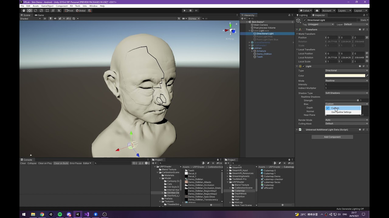
}```So I'm trying to do some Half Lambert Lighting and used the Shader Graph Feature Examples graphs as a basis for custom lighting.
It seems to work fine, but when I enable shadows on the mesh, I get this odd banding.
Shadows Off

Shadows On

Any idea why this is happening?
(Ignore the rocky sphere in the back, it's using standard lighting as a comparison.)
Shadows have to be projected based on whether a polygon is occluded from the light source, which always happens at a specific angle
Non-projected shading can have whatever smooth ramp you want instead
Usually the shading matches the shadow so the jagged border is concealed
The jaggedness itself happens because shadow casting is limited by shadowmap resolution, as well as the geometry normal prior to any smooth interpolation
Sorry I don't think it's clicking. Where are these faces even getting a shadow from?
Shadow casting from your light source, which you said you enabled
You said that shadows are projected based on whether the polygon is being occluded from a light source. This region is for some reason in shadow. What is it getting occluded by?

These guys?

Like the other side of the mesh?
Yes
Wouldn't be much of a shadow if shadow casting geometry in front of the light wouldn't cast a shadow
Not untrue 🤔
So then what's the solution here? Is there a way to make it so this shadow doesn't appear while making sure the object is still reactive to other shadows?
You might be able to disable shadow casting but keep receiving shadows on, though that means your objects don't have any of the expected self shadowing
Usually your shader shouldn't be involved with casted shadows at all if the shader's light attenuation is too smooth to cover the rim
Well at least it receives shadows correclty while casting is off.

But how would you get it to both cast and receive withoust projecting shadows onto itself? Windwaker for example did it.

Hey guys i'm having a little trouble understanding something about the pipelines, I learned to write HLSL shaders for built-in pipline, but it seems everything has moved to URP. I am trying to understand how can I keep doing HLSL shaders for URP instead, I do not want to use shader graph. Any shader i write seems to work completely fine in URP project but i'm a bit unsure if i'm doing the right thing.
I am not sure if this is the correct locate to ask. But I am trying to create a 2D top down game. I want to add water similar to how forager did it. Not sure how to do it. Do I create sprite then animate it?
I was thinking maybe I have to create a shader but not sure how to make it interact properly with the bottom tiles.

This is probably just sprites. I don't see anything that might require a separate shader in this screenshot.
One thing to mention the waves do move. But it could just me the sprite being animated. So I'll go ahead and create my wave sprites. Thanks 🙂
Yes, it's likely a sprite animation
Hey I created the same tileset. Just wondering if you know how they got them to align properly. If you don't thats ok thanks anyway 🙂


Not sure. Maybe ask in #🖼️┃2d-tools
Ami missing something, or is there no Perlin Noise node in Shadergraph? Perhaps i missed a package? URP
Sorry messaging again. I think that forager uses a shader not sprite animation. This is a video of it bugging.
how do I go about making this?
Donno about that. I think the submerged tiles are just animated like that. I don't see anything that would require a shader here.
That being said, you can probably implement it with a shader as well. It's just gonna be more work imho.
There should be. Did you look at the documentation?
Sorry I’m still new to sprites and game dev general. In the video I shown, did they create sprite animation water only or water + wall?
Bah! Thank you. i did not expect Perlin to be bundled with Gradient :/
So when the object receives shadows, a copy of the shadow appears below the mesh.

The sphere isn't even casting a shadow down in this case.
Do you know how I get rid of this copy?
if it is not a custom shader, perhaps ask #archived-lighting ?
Is it a custom shader 😛
Trying to implement Half-Lambert lighting
wouldn't that just be Bert? 😁
Bro I actually looked up "Bert" lighting
I hate you
!LOL 🙂
It could be that, or it could be an animated transparent water sprite overlayed on top of a wall sprite.
It's not a "copy", but that both sides of the mesh are in the way of the shadow
The casted shadow should be blended with the directional light attenuation
So you'd probably want to apply your custom light ramp only after you've multiplied the casted shadow and light direction together, or use a blending method that doesn't stack them like "darken"
Oh I think I see what you mean. Like I get a 0 to 1 range of light intensity values across the whole object (shadows contributing to that) and then I map those values into whatever gradient I want?
wouldnt this bottom region still end up dark though?

Well actually... hmm.
If I do all the calculations within that standard 0 to 1 lambert range, then I can just remap to half lambert.
This bottom shadow will be be 0 with everything else on the opposite side of the mesh.
But then wouldn't the shadow get affected by the shifting and look spread out?
Ugh
No
With directional attenuation to 1 to 0 range occurs evenly across the whole mesh as per normals
With casted shadow attenuation it happens only across the penumbra / shadow terminator which by comparison is usually an extremely quick transition
Which means the shadow terminator will likely still clash with your soft half lambert shading
Games that use that type of shading (Source and Valorant apparently) for that reason do not have the characters receive any projected shadows at all
Instead opting only to get shadowing from baked probes
Wind waker does not seem to use half lambert style light attenuation that'd risk exposing the shadow terminator at 0.5 attenuation, even if the characters also don't seem to receive projected shadows except via probes of some sort
Hmm. Ignoring half lambert for a second. If I wanted to have a mesh that was fully lit everywhere (basically unlit behaviour) but received shadows, what are my options assuming I don't want shadows appearing through the backside of my mesh?
I guess you could flip the directional attenuation and blend that to the casted shadow attenuation with Lighten blend mode
It might look weird though, since the side of the object that's away from the light would be less in shadow
Damn this sucks.
I think the easiest way is to clamp the bottom of light attenuation, so instead of having 0 - 1 light range, you have 0.5 - 1 light range, this should be different from your half lambert lighting as half lambert, remap from 0 - 1 to 0.5 - 1
I recommend analyzing more carefully how old stylized games did their thing for ideas of how you want to buid your own stylized look
Most of them got by with very sparse shadow casting and looked fine
Unity's and other modern games' shadow shadow casting techniques have specific limitations especially especially when it comes to hiding the shadow terminator
It never mixes very well with toon shading, so workarounds are worth looking into
Or even alternate shadow techniques like stencil shadow volumes
Stencil shadow volumes?
Hi 🙂
I'm using Unity 2022 and did this on shader graph
But I can't make the alpha work, it always displays me the black area. I tried to come up with multiple solutions but none of them work. I'm pretty sure this used to work on my previous projects, do someone has any idea to solve this?


Alright I saw the google symbol 😛
But I feel anything involving stencil tomfoolery will be tough in URP
Your alpha clip threshold is at 1 so pixels will never be clipped by transparency regardless of alpha value
It's possible you'd want instead to change the material from opaque with alpha clipping to just transparent
Right now it is transparent

Also I believe Unity has a (relatively) new graph type called Sprite Unlit which lets materials from Shader Graph behave a bit better with the Sprite Renderer controls.
I'm using it for particle system, would this work as a sprite unlit?
Also, if those are particles the particle systems uses vertex color for particle color and alpha, not any other color property
Sprite graph is inteded for sprite renderers, not particle systems
I honestly think it might still work.
Pretty sure the Sprite graph just does some vertex coloring/applies masking values.
Could, but it's not intended
Aka stuff the Particle System can control too.
Or so I assume anyway
Additionally shadow volumes are a 100% different and custom shadow system, and there doesn't seem to be any existing URP compatible solution
Is vertex color entirely handled by particle system?
fun
Yes, when it generates the particle geometry it also writes to vertex colors, as well as custom vertex streams, if any
Alright, I'll check that thanks!
Like I implied you don't really need much in the way of shadows, especially likely not fancy custom systems just to have nice stylized lighting
But it's important to understand the benefit of features available to you, like probes
In Wind Waker when a character goes into a building's shadow, the shadow is not projected onto the character but the whole character is simply darkened
Very simple and apparently good enough for most
Really what I'm just trying to replicate is this.

The card shadow.
The rest of the board seems to be unlit to me.
Relying solely off the painted art style.
If it's all top down it doesn't seem like you need to worry much about how the shadows look on the underside of things, or even at shallow angles
Not untrue, but it bothers the backside of my brain.
😛
It worked! 🥳

I'm using the texture shown at the bottom right, to map the white pixels to a buffer in my compute shader, and those values are written to my tilemap system.
Right now I'm using the full resolution texture for this, but as the tilemap has far less resolution than the texture, would it be worth using a mipmap instead?

I believe you'll be sampling the texture only for each tile, so it doesn't really matter (unless your source texture had noise or small details that can cause eccentric results)
If the texture was huge, you might be able to save some memory by not loading it in full resolution, but it's not
(Based on my knowledge sampling a lower res mip level directly would save VRAM, but to not load the full texture into RAM you'd need some type of texture streaming, but again that's likely less than a marginal issue here)
ah, if its only really good for making it more optimal then I wont worry
I wasnt sure if a lower resolution texture might produce a better result in the tilemap. The higher resolution texture has a lot more information thats going to waste
One concern is that I'm doing a very basic check where as soon as any pixel is white, that tile is marked as being filled.
[numthreads(8,8,1)]
void CSMain(uint3 id : SV_DispatchThreadID)
{
  uint width, height;
  Layer0.GetDimensions(width, height);

  float l0 = Layer0[id.xy].x;

  if (l0 == 1.0f)
  {
    int2 gridCoord;
    gridCoord.x = id.x / (width / MapWidth);
    gridCoord.y = id.y / (height / MapHeight);

    int bufferIndex = gridCoord.x + gridCoord.y * MapWidth;
    Result[bufferIndex] = 1;
  }
}```so even the smallest overlap will fill the tile. But if it was lower resolution, theres less chance for that to be the case
With a lower resolution the image will be blurrier with bilinear filtering, so less pixels would be white
You'd rather check if the color is > 0.5f, or some threshold adjustable to taste
How can I modify the ShadowCaster pass from blurring the shadow edges? I don't want the smooth transition

The ShadowCaster pass doesn't determine whether soft shadows are applied. The surface the shadow is being cast on determines that, or a separate full screen shadow pass in some cases.
You can disable soft shadows globally, but not per shadow caster.
Aha thanks
hey guys, i got recommended to try and use channel packing for my textures, but I can't find any documentation on them for URP. Is this a shader thing? How do I get it to work?
Here's an example
https://m.youtube.com/watch?v=m5bP-xc6Sgs&pp=ygUWU2hhZGVyIGNoYW5uZWwgcGFja2luZw%3D%3D
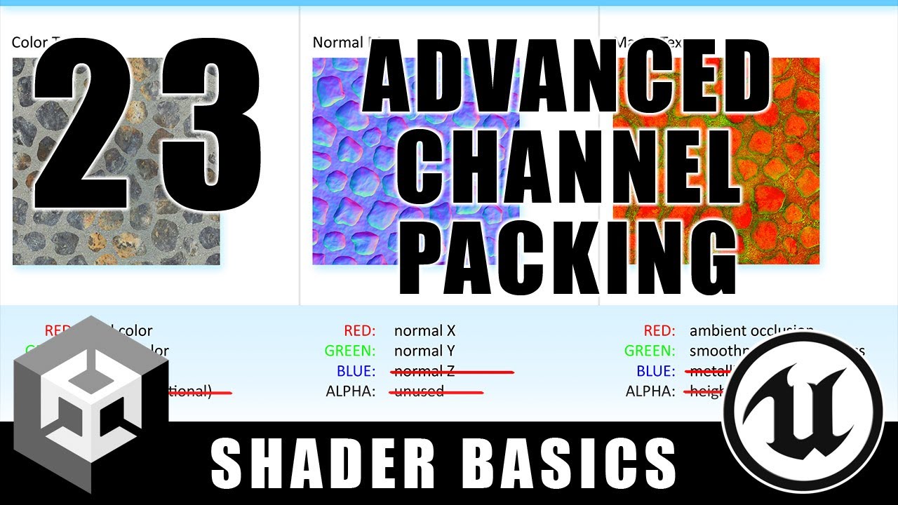
In this shader tutorial, I show an advanced technique for packing data into texture channels that allows you to represent all of the texture data needed for a material in just two texture samples. Using this method saves both texture memory and performance, but since you're packing non-normal data in with the normal map, you do lose a little bi...
Guys, do triple a games make all of their own shaders?
I'll give this a watch, thanks!
so it looks like the Complex Lit shader has the channel packing which is what I'm after
how do I enable it? the UI just looks the same as the regular lit shader
What do you mean by enabling it?
There is no enabling or disabling
You just stuff textures into channels
Unless you mean doing that in unity
so say I generate the required channels in R, G, A colors
it should be in a single image/texture right?
and I just drag and drop the same image into the metallic/occlusion/smoothness inputs?
No, single texture, 4 channels
You can switch between channels and see what each one contains
You would usually pack textures like that in photoshop
There are probably online tools for it or something
yeah so if I've got it right, I should have a single texture containing metallic/occlusion/smoothness in the R/G/A channels - then in Unity I drag and drop the same image into the metallic/occlusiom/smoothness maps? Does that mean the shader is only doing one texture read or have I got my understanding wrong?
You understand the purpose bjt not the method
You should drag the individual outputs into the channels they need to be in
So if metallic is in red, you drag R to metallic
G to occlusion or whatever the channel are
I think this method is for something you create in shader graph - like you take the single texture and read the R, G, B , etc.
I found the Complex Lit shader form Unity's documentation which seems to support channel packing already, but I wasn't sure how to put those RGBA channels through
lordantares1 apperas to be talking about how you create a packed texture, where you merge several grayscale images together
a shader would have a single Texture property that you throw this packed texture into
You wouldn't have multiple separate texture properties
yeah, this bit is where I'm confused about because the Complex Lit shader says it supports a packed texture, yet I'm seeing multiple input spots for textures
like thiua\

Where did you see that?
oh, I searched for "packed" instead of "packing" and instantly gave up
also, that's very poorly named
it has nothing to do with the actual "base map" texture
I see what they're getting at tho
So you do assign the same texture to multiple properties
When you do that, the texture still only has to get loaded onto the GPU once
I think the idea is that it checks the red channel of the Metallic map, the green channel of the Occlusion map, etc.
So grayscale textures work as expected
But a packed texture will also work correctly
so uh
I just put the same texture into the different properties and it should just samples the same texture once
it's a bit weird that there's no normal map property, I would have thought that it would be a common thing to want to pack
Normal map is already using all the channels(or at least 3), so there's no much space to pack anything.
Hey guys, I have sort of hit a wall and I could use some help.
I am trying to control my shader via code which will be triggered by in-game events that take place.
In this basic proof of concept attempt, I simply want to update a grid to shade the tiles different colors.
The problem is, as far as I can tell my calculations are correct, and I am passing the right values, but the shader is only ever updating the last tile in my grid to be colored by the highlighting, regardless of where I click.
In this case, I clicked where the mouse is, and it colored the last tile. It always colors this same tile, regardless of input position.
My grid is comprised of a UV node to start which we then plug into a tile node, with the grid size. We then split that off to our custom function node for the highlighting work, and a fraction node for generating the rounded rects which we are using for grid tiles.
Happy to share the shader graph file or pictures of it, if it helps!
Just trying to understand if I am even in the right ballpark, and if so, what might cause the highlighting to only ever be applied to this particular spot?

void GetHighlightData_float(float2 scaledUV, out float4 highlightColor, out float highlightIntensity, out float4 debugColor)
{
    // Initialize outputs
    highlightColor = float4(0, 0, 0, 0);
    highlightIntensity = 0;

    // Get grid position
    float2 gridPosition = floor(scaledUV);

    #ifdef SHADER_API_D3D11
    // Loop through highlight buffer
    for (int i = 0; i < _HighlightCount; i++)
    {
        HighlightData highlight = _HighlightBuffer[i];

        // Check if current grid position matches highlight position
        if (gridPosition.x == highlight.position.x && gridPosition.y == highlight.position.y)
        {
            // Set full color with alpha
            highlightColor = highlight.color;
            // Ensure intensity is properly scaled
            highlightIntensity = saturate(highlight.intensity);
            break;
        }
    }
    #endif

    // Update debug visualization
    debugColor = float4(
        gridPosition.x / 10.0,  // R shows X position
        gridPosition.y / 10.0,  // G shows Y position
        highlightIntensity,     // B shows if we found a match
        1                       // Full alpha for debug
    );
}
You can disable "soft shadows" and/or use a step function on the shader of the object receiving the shadows
But the issue may turn out to be that the shadowmap is made of pixels and it'll look jaggy if unsmoothed
I've got this strange jittery issue (I click to update the texture which is why some tiles get tinted white) that only seems to occur around the edges of the texture
I'm not too sure why that could be happening. Thats the shader code, which is pretty much the same as how it was previously
#pragma kernel CSMain

RWTexture2D<float4> Layer0;

int MapWidth;
int MapHeight;

RWStructuredBuffer<int> Result;

[numthreads(8,8,1)]
void CSMain(uint3 id : SV_DispatchThreadID)
{
  uint width, height;
  Layer0.GetDimensions(width, height);

  float l0 = Layer0[id.xy].x;

  int2 gridCoord;
  gridCoord.x = id.x / (width / MapWidth);
  gridCoord.y = id.y / (height / MapHeight);
  int bufferIndex = gridCoord.x + gridCoord.y * MapWidth;

  Result[bufferIndex] = l0 > 0.0 ? 0 : -1; //-1 means no match
}```Thats the actual C# code that calls the shader
  public void GenerateZonesFromLayers(TerrainLayer[] layers)
  {
    ComputeShader cs;
    TextureHelper.LoadComputeShader(out cs, "LayerZoneCompute");

    TerrainLayer layer0 = layers[0];
    cs.SetTexture(0, "Layer0", layer0.LayerMask);

    cs.SetInt("MapWidth", _mapWidth);
    cs.SetInt("MapHeight", _mapHeight);

    ComputeBuffer outputBuffer = new ComputeBuffer(_mapWidth * _mapHeight, sizeof(int));
    cs.SetBuffer(0, "Result", outputBuffer);

    TextureHelper.Dispatch(ref cs, 0, _texSize);

    int[] outputData = new int[_mapWidth * _mapHeight];
    outputBuffer.GetData(outputData);
    for(int x = 0; x < _mapWidth; x++)
    {
      for(int y = 0; y < _mapHeight; y++)
      {
        _map[x, y].Zone = outputData[x + y * _mapWidth];
      }
    }
    outputBuffer.Release();
}```I don't understand what's actually creating that texture
thats where it comes from, when I create a new TerrainLayer. It just reads a texture2D as a placeholder texture
    TextureHelper.CreateRenderTexture(out LayerMask, texSize);

    var testTexture = Resources.Load<Texture2D>("tex/test2");
Graphics.Blit(testTexture, LayerMask);```I'll generate the LayerMask texture later, but theres no need until the shader is working correctly
the only thing that changes is the property when I click on a tile, but thats unrelated to the zones
this isnt the first time I've encountered this same jittery effect when using a texture in a shader this way
Or do you mean the texture that creates the red tiles?
Kind of both, really
I don't see why there are red tiles at all
(is the problem that the red tiles are changing?)
not at my PC now, but the shader that creates the white colour when I click, is exactly the same as the one that creates the red color. But it reads the zone property not the isClicked
it just figures out which tile the current pixel is inside
its something like this
  int2 gridCoord;
  gridCoord.x = id.x / (width / MapWidth);
  gridCoord.y = id.y / (height / MapHeight);
  int bufferIndex = gridCoord.x + gridCoord.y * MapWidth;

  int zoneValue = TileBuffer[bufferIndex];

  if(zoneValue == -1)
  {
    Result[id.xy] = float4(0,0,0,0);
  }
  if(zoneValue == 0)
  {
    Result[id.xy] = float4(1,0,0,1);
}```yeah, it shouldnt be changing every time. A tile either is or is not located above a white pixel in the layer texture
Are there any good resources on shader keywords?
I kinda have difficulty understanding them and deciding if I need them
Heya, can someone explain to me what exactly CommandBuffer.DrawProceduralIndirect is supposed to do exactly? Is it just rendering one part of an index/vertex buffer or is it rendering all of it with the indirect args?
The args buffer specifies the index/vertex count per instance, as well as an index/vertex offset. So you can use it to render a section of your buffers, or all of it, depending on what you specify in the args buffer.
what does the args offset do exactly? and what should I set it to?
documentation isn't exactly helpful
Args offset is just where in the buffer the draw call should be reading its args from within the buffer you provide. It provides more flexibility, so you could for example pack more than one set of arguments into one buffer and have each draw call read its own section of it.
But in the case where you only have one set of arguments in one buffer, you'd always set the offset to 0.
That's different from the index/vertex offsets I mentioned.
There are two different versions of DrawProceduralIndirect. A version where you provide an index buffer and a version where you don't. The arguments mean different things depending on which one you're using.
can you walk me through it please?
or link me to some actually helpful documentation?
The docs explain what the arguments mean for each one.
When providing an index buffer:
Buffer with arguments, bufferWithArgs, has to have five integer numbers at given argsOffset offset: index count per instance, instance count, start index location, base vertex location, and start instance location.
When not providing an index buffer:
Buffer with arguments, bufferWithArgs, has to have four integer numbers at given argsOffset offset: vertex count per instance, instance count, start vertex location, and start instance location.
If you don't intend to use instancing, you can ignore "per instance", "start instance location" and set "instance count" to 1.
I can probably explain better if I know your intention with this method.
say I have a list of unique meshes I want to render in one single command (unless I am completely misinterpreting drawprocindirect) and I put it all into their big respective buffers - vertices, indices, and the commands ofc - would I be doing this?
cmd.DrawProceduralIndirect(indexBuffer (my triangles), Matrix4x4.identity, material, -1, MeshTopology.Triangles, commandBuf (indirect args), 20 (5x4 bytes), matProps (which I have set my indices, vertices, and other stuff I'll need in the shader));
more context: rendering voxel chunks efficiently ig
also want to give myself better ways to cull with the computebuffer parameter for my args
The indirect version is only useful if you want to be able to change the indirect args from a compute shader, such as GPU culling. Is that something you intend to implement?
yes yes
wait so there's no real way to render everything all at once with the indirect args? Something similar to OpenGl's glmultidrawarraysindirect
I have to like, loop through all my commands with the offset?
The old DrawX methods do not support command count, but the new RenderX methods found in Graphics do. It looks like that hasn't been brought to CommandBuffer yet.
https://docs.unity3d.com/6000.0/Documentation/ScriptReference/Graphics.RenderPrimitivesIndexedIndirect.html
so with this I just set the command count to the amount of commands I have - and that acts like multidraw?
Yes, assuming your args buffer has multiple commands in it.
Nice! one last thing, can you please explain to me more in detail the properties of the IndirectDrawIndexedArgs struct? Mainly the baseVertexIndex; while I was experimenting with it, I found it has no impact to what rendered. I assumed it meant the offset to each index because all the indexes in a combined buffer would lead to the start of the vertices buffer rather than their respective vertices, however it had no effect when I attempted to change it...
The thing I was trying to do was take two different meshes, combine their vertices and indices into their respective buffers, and make two commands for them so they would both render with the one command - which was the RenderPrimitivesIndexedIndirect method - however if the two meshes I set in the inspector were different, it would work fine but using two different meshes would absolutely break the meshes rendered with the second command. It was obvious that the problem was the indices of the second command/mesh where using the vertices of the first, however changing the basevertexid did literally nothing
Also sorry for bothering
I haven't used it before, so I'm not sure, but I can't find anything that would suggest that it wouldn't work the way you assumed.
The equivalent argument in D3D11 is documented as:
A value added to each index before reading a vertex from the vertex buffer.
which makes sense and is critical for my use
however is doing nothing
I've tried using the correct offset values and have tried using some random constants
to no avail
Oh, but I don't think it will change what you get from SV_VertexID in the shader. That apparently always acts as a counter starting from zero.
that's what GetIndirectVertexID(svVertexID) is supposed to be used for aparently
I don't see any case where baseVertexIndex gets added to svVertexID here
https://github.com/chsxf/unity-built-in-shaders/blob/master/Shaders/CGIncludes/UnityIndirect.cginc
In fact, it's not used in any of the functions, it can only be accessed directly with GetIndirectDrawArgs
ooooh so I should be using the args directly in the shader myself?
makes so much sense
I've never had to do that, but I've never used baseVertexIndex or multi draw.
though honetly thought it'd be trivial to have the engine be doing that for you, but what the hey, this is a function designed for flexibiltiy anyway
Anyways thank you so much! You have been such a great help.
How would I fix this issue? I want the face in the middle to not be visible while maintaning transparency everywhere else

Which render pipeline and is it an option to modify the geometry instead
URP and no
I really need to do it this way for my uses
What do you mean by "your uses"
Separated from what?
Are you making these meshes? If so, can you just separate the middle part as a child object and disable it?
Or not have it at all, depending on what you need it for
Hello, im still learning, so im having a hard time understanding some things about shaders.
I have a 2D URP project and im trying to use dither transparency controlled by alpha clip threshold. If my shader is set to "Lit" which is for 3D, alpha clip threshold at 0 means fully visible while getting to 1 is more dithered until invisible at 1. On the other hand, as a "Sprite Lit" shader, everything is the same but alpha clip threshold 0 is already dithered for some reason. That is not what I want. I want the "Lit" behavior but on a "Sprite Lit" shader. I have tried many workaround to no avail.


been playing with the example https://toqoz.fyi/thousands-of-meshes.html
at this point though, I'm scratching my head at shaders. I like the instanced shader they tossed together to give them unique colors, but those alone won't support a sprite on the material. (I've at least tracked down that it's probably a property of shaders).
is there a shader people like to use with sprite rendering? one that (presumably?) has a z coordinate as well?
Michael Palmos
GPU instancing is a graphics technique available in Unity to draw lots of the same mesh and material quickly. In the right circumstances, GPU instancing can allow you to feasibly draw even millions of meshes. Unity tries to make this work automatically for you if it can. If all your meshes use the same material, ‘GPU Instancing’ is ticked, your ...
I wonder. Feels like a tall order to do sprites, individual scales, colors and rotations, all crammed in a shader that I can push into a bulk mesh render.
Any shader expert here? I need a shader to be made, i can pay for the help
!collab
:loudspeaker: Collaborating and Job Posting
We do not accept job or collab posts on Discord.
Please, use Discussions to promote yourself as job-seeking, advertise commercial job offers, or look for non-commercial projects to participate in:
• Collaboration & Jobs
cant find the collab channel / thread
Click the link in the bot message.
hm. is there a summary of the features the in-house shaders support? instancing, alpha blending, et cetera? I'm even just at the point of trying to navigate this, but I figured I'd ask...
Like there are 2 meshes
Working in shader graph and trying to offset just the alpha channel of a texture on the XY axis. Is this possible? From what I can tell, the Tiling and Offset node could possibly help, but I have no clue how to modify the pixel positions on the 2D output from the alpha channel or math nodes. Alternatively, just being able to offset the XY position of any 2d output from a math node would be helpful

Hey, is it possible in a hlsl shader to sample from sth like a shadow map if there is a shadow rendered by unity at a specific position (in screen or world space) in urp and how would you do that?
hello, i bought a shader that is supposed to do a wind distortion, but the sample scene i got looks like this:


Get the [Free Asset] Fan Spin Effect: Wind Particles package from SOLODREAM CREATION and speed up your game development process. Find this & other VFX options on the Unity Asset Store.
vs that ^
its not telling me a specific error either, so im not sure whats wrong
My guess is that plain is what's supposed to render the distortion effect, but the correct shader is not applied to it for some reason. Check the plane material.
I'd also check the readme file included to make sure you're using the asset correctly. Perhaps it's only effective at runtime or something.
any hints how to make my simple square spriterenderers do this, what keywords/shader nodes are related to this effect?

I just want box spriterenderers that mixes with other when they touche
It's not a simple keyword or a node. This could be a pretty complex effect to implement just via shaders.
It also depends if you want it to render just like in the screenshot( only the border of the mesh?) or is it just a simplified example, and you actually want textures to be rendered in that area somehow.
they wil literally just look like white boxes with edges
when the edges touch, the touching and overlapping parts are not visible
Then the easiest way I can think of is either:
- merge the individual rectangle meshes and use a mesh renderer to draw the combined mesh.
- render all the sprite renderers into a mask render texture and use that in screen space or something.
The drawing of the outline is a separate issue.
If using combined meshes, you'll probably need to adjust the uvs of the mesh and use the uv values to determine how close to an edge a pixel is.
If using the mask approach, you could sample several pixels to the sides to see how close to the edge you are. That's probably gonna be way more expensive than the first approach.
Maybe there's a simpler way, but I can't think of anything else.
thanks, i'll try looking for other solutions first, I'm not that good with working with meshes just yet 
this sounds easy though, might worth the try if desperate
so I want to display point data with a shader. Aka to have small bubles or squares at the data I have. I cannot use compute shaders or VFX graphs. I thought I can save my position data into texture, and then combine that texture data with position somehow and do something with that data, like adding extra visuals or etc. But I failing to do it. Maybe someone have to suggest different approach?
#pragma multi_compile_fog what does this means?
Usually, anything starting with a # is something that tells additional info to the compiler. You have #define which are very common in C++ code to define a certain keywords, set it's value or define a macro. #pragma on the other hand seems to adjust the behavior of the compiler.
In this case, it tells the compiler, to compile several variants of the shader for different fog types:
https://docs.unity3d.com/2018.4/Documentation/Manual/SL-MultipleProgramVariants.html
for example I just use exponential fog in my scene, so I dont need that fog compiler to include the other modes which are unnecessary, in such case which practice are better to write shader efficiently
@kind juniper
I don't think there's a keyword for each specific mode. If you want only specific fog type, you'd probably need to code it yourself in the shader. At least not published anywhere. If it is anywhere, that's in the source code. So maybe look at the built-in shaders source code.
Is there a specific reason you want to avoid using the multicompile?
i got this, thanks
nothing in specific, i was just curious about it
Hello, I picked up a PS1 Style shader graph for URP on github but it doens't have support for normal maps, I'm new could someone please tell me if there is a spot for me to hook up my normal map + normal strength variables from the blackboard so that they appear ingame ?


does anyone know how to fix this error for a shader?

Hello guys, why are one of my shaders staying pink even though they are not supposed to? (I am using URP)

This magenta color from a shader usually means there is an issue with Shader's Custom Node in my experience.
Perhaps there is an issue with the shader code.
I will check the shader again.
The other possibility is, if you just switched to URP, you may need to run the material conversion to update all your project materials to be URP materials.
Edit > Rendering > Materials > Convert

Maybe re-create the material and re-apply the shader. Idk what else would cause the magenta coloring like that.
Hard to say since I don't know the timeline of when you created this material & went to URP. It may or may not be the actual issue.
Unity cannot auto-upgrade custom shaders
it knows that "Standard" should be replaced by "URP/Lit"
that's all
It has no idea what to do with this third-party shader
I mean, i just made the shader today
And i got URP like 2 weeks ago
No, I wrote the shader today.
okay, so you need to write it in a way that's compatible with URP, then
Oh okay.
If you use the Shader Graph, that should be straightforward. If it's a ShaderLab shader, then I'm not familiar with how that works -- I only hand-write shaders in the built in RP
If it's ShaderLab, then right click on the shader asset and reimport it. You should see shader compilation errors in the console.
hello i made a fullscreen shader in unity hdrp but this shader is not used in the build version. does anyone know why?
How are you using the shader?
It might not be getting included in the build if Unity doesn't think anything is using it
i use it with custom pass
a simple shader that provides thin stripes on the screen


Okay, that ought to be pulling the shader into the build
You could double-check by forcing the shader to be included
Project Settings > Graphics
then put it in the "Always Included Shaders" list
(you have to manually change its size, very silly)
Hey, im working at an instancing shader atm and currently i am stuck with the problem that the instanced cubes/meshes arent being writen to the depth texture therefore this collides with my raymarching shader any ideas why that could be? https://pastebin.com/pHJK03Ay
Pastebin
Pastebin.com is the number one paste tool since 2002. Pastebin is a website where you can store text online for a set period of time.
Hey a bit of a late response, but you could check out this tutorial of mine, it does not use shader graph but should show you how to make an edge detection shader
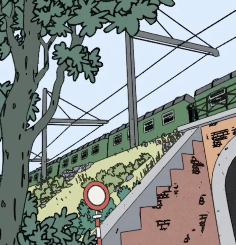
🖍️ A tutorial on how to render outlines as a post-processing effect in Unity 6 and Unity 2022. Makes use of an edge-detection technique based on depth, normals and colors, and can be used in Unity's Universal Render Pipeline (URP) using the new Render Graph API. Can be used for game mechanics or stylistic rendering.
Oh cool, thanks!!
thank you but i understand this is not the only problem
when i created the shader graph i kept getting error and warning messages i didnt care about them because the shader was working fine in the editor
i dont understand the shader system at all 

I'm getting sprite popping/swapping when my camera moves or zooms out, and i'm 99% sure it's coming from some internal issue where a material with multiple instances and sprites are deciding to coalesce to the same sprite image regardless of assignment. Is this a thing? If so what's the best practice for material assignments versus unique sprite needs?
The material in question is just Sprite-Lit-Default, but i remember running into this in the past with a custom material which i solved by making a unique material per texture (which felt super counter-intuitive, but did solve the problem). Thanks in advance!
Can we stop unity from autogenerating a material with every graphs in 2022+?
Hey guys. I'm working on a 2D game that uses sprites and I have a question. I'm pretty sure it's possible to have a black and white sprite and then create shader that replaces the shades of gray with a color palette. Then apply that shader on the material my sprite is using.
I thought maybe that's something I can use for my butterflies, instead of creating dozens of sprites to cover multiple color variations.
But is it possible to have the material display different colors on different butterflies at the same time or I would have to create one material per color palette?
Just wanted to post an update in here and ask a question while I was at it!
I am working on making a shader for my game and I thought it would be a fun challenge for myself to learn shaders. So far so good, I can render planes with their own materials on them for individual grid highlighting. I was just curious what suggestions people had for controlling the rendering of this on a per player basis. For example, if I want to enable or disable showing this shader, on a per player basis in a multiplayer game, what would be the best approach?
Imagine this grid is being used for a turn based game, and we only want too show it to player 2 because they are choosing a target for some ability they used, or something along those lines. I am not sure what to look up from here that will help me reach my goal so I thought I would ask here.
My fallback plan is to just do the below approach, and render each grid to a different player camera.
Thanks!

My bad, didn't mean to reply to you with that. I think to solve your problem though @inland ibex you will want to apply the color variance from the shader itself. Quite possible to do with shader graph.
Edit: Maybe something like this:
https://www.youtube.com/watch?v=firdoL0pjiI&ab_channel=AETuts

This is a quick tutorial on making a material that assigns a random color from a gradient based on the position of the object.
This material is part of the URP Material Pack Vol 2:
https://bit.ly/lwrp-materials-2
Checkout my assets for more Tuts!
...
That's not really a "thing" that I know of, at any rate especially if it happens with the default material
You could show a video of what it looks like and when does it happen
More of a #🖼️┃2d-tools subject if you're not using custom shaders
#🖼️┃2d-tools message video posted here, thank you 🙂
i just solved this problem and its solution was very stupid
i just changed the operating system language to english all the errors I received were fixed and the shader worked flawlessly in the build version
Has anyone here successfully implemented compute shaders in a mobile game?
How widely are they supported on mobile devices in 2024?
They are supported in OpenGL ES 3.1 and up. So, the answer to your question can be found by asking how many devices support OpenGL ES 3.1 or above. Surprisingly, there's not really a good resource for this, but I would guess the majority of phones made after ~2016 will support ES 3.1.
Thank you. I'm aware of that, however I wanted to know how compatible they are in 2024. Looking at old messages (2023) on this server, it looks like they didn't work on quite a few mobile devices, so I was wondering how more experienced devs went about it.
I wanted to mention it, because I figure it's easier to find out how widely supported OpenGL ES 3.1 is, instead of specifically compute shaders, because they overlap the same devices.
Yup, it looks like many manufacturers don't bother maintaining the drivers to support compute shaders even though their products have 3.1+ or Vulkan.
The issue is more granular than that. Pretty much any device you should be targeting nowadays 'technically' will support compute. However, what you'll find is that due to driver bugs, half of what you actually want to do will cause issues that need workarounds.
Hey all, I don't want snow tree effect on distortion as this tree is ahead of plane? How can I resolve it?

Sample the depth buffer and compare it against the current depth.
I'm unfamiliar with your shader setup so it's difficult to explain how to do that
Here is the shader.

Apparently there's a scene depth difference node you can use https://docs.unity3d.com/Packages/com.unity.shadergraph@17.0/manual/Scene-Depth-Difference-Node.html
Perform different logic based on whether the difference is positive or negative
(in front or behind)
Thanks, Let me try.
How do you know if it's a driver bug or not?
Simplest way: If your code works on 4 phones but not the 5th, then it's probably a driver bug 😄
Good to know, thanks Alex!
hi, it is not really shaders, but I am not sure where to post. I am trying to display a cylinder in wireframe, but there are too many polygons in it. Are there cylinders with less polygons ?
I'd just make your own model in any 3D tool
Hey im using a psx shader in my unity game and it seems to not be reacting to light i have hdrp render pipeline any help?
I have a multi sided sprite shader for a game, and for some reason it isn't receiving shadows/lights or casting shadows. Could anybody help me?
Hay, does anyone have any clue how to implement MSAA using the RenderPass/SubPass system in a custom SRP?
Me: "Why do my decals look strange? They seem to not be fully transparent. How odd."
- Spends the next hour researching and trying things. Eventually takes a break and closes Unity.
- Comes back 3 hours later and opens Unity.
- Problem gone. Seemingly no reason why.
We take those.
why would you want to have psx shader to react to light?
So I'm trying to make a very common shader, an edge shader. Anyone have recommendations for a solid modern tutorial for this? It seems there are a lot of ways to do it, just not sure which direction to pick.
Ok there are fewer options than I thought, most tutorials are for outline shaders, which won't work, and the rest are shaders that are done at the scene level... but I want it on a per mesh basis instead.
Well what do you mean by "edge shader".
Do you mean when the mesh intersects another, something happens along that border?
Or do you mean something happens on the edge of the mesh, like an outline?
@steel notch like an outline, but from what I've seen of outlines, they are projected away from the mesh (or behind it?) and I don't know how that interactions work with a transparent shape in something similar to voxel terrain.
I guess the closest thing would be stormworks building UI:

There's a lot of very different outline techniques https://ameye.dev/notes/rendering-outlines/
intresting
according to this edge detection is a full screen pass, bummer
So one of the outline methods is my only option
does anyone know how i can make a compute shader that adds shadows to tile maps sorta like terraria but doesn't rely on light but only on distance from the edge of clumped tiles. maybe it would render black square cells with certain amount of alpha depending on how far from the edge it is and then blur it all. OR have a reference to a website where i can learn where to do it.

Terraria uses a type of flood fill algorithm for its tile based lighting, which is similar to a distance field generation algorithm
Both of which could be useful techniques for you
I wonder if https://bgolus.medium.com/the-quest-for-very-wide-outlines-ba82ed442cd9 would be applicable there..
I'm Trying to make the sprites glow. but Why they have some outlines if I use my Glow Material?

It's Default Material

and this happens when I change Material


This is the Material / Shaders info
It seems the shader graph is set to opaque
this is my shader graph

followed a brackeys tutorial and its the same
yet isnt working
all settings the same
right i somewhat fixed it
but on the emission nothing is happening
no blue
where should I look for info about #pragma multi_compile _ _MAIN_LIGHT_SHADOWS
#pragma multi_compile _ _MAIN_LIGHT_SHADOWS_CASCADE
I'm trying to access shadow maps from code in URP
Is there anyone familiar with the RGB mask workflow in Unity?
I want to use rgb mask workflow for my model in unity. For example I want the red color to be rust, the green color to be dust, the blue color to be scratches.

how can i do this in unity?
And what tutorial can you recommend?
Why not bake this in with the base color
Otherwise you can pack your rgb texture and sample twice, once for regular base color and once for your rgb mask, and blend in such a way that your mask overrides the base
I.e. mask is white, no mask part is black
you sample the mask texture, then multiply red channel with rust texture, green with dust, and blue with scratch, then you add them together, but you need to care to make sure the rgb channel for one pixel to never exceed one.
Or, you ignore the red channel, and interpolate from rust to dust using green channel, then interpolate from that result to scratches using blue channel, that way you dont need to worry about 'oversampling'... Also you can use the red channel for one more texture slot
Is there any way of making a Shader Graph for using in TextMeshPro?
Technically I believe there is but I don't think there's any official examples or much guides at all for it
The only problem is that the TMPro relies on a shader to deduce the glyphs from the SDF texture so you would have to replicate the same in your own shader. You may be able to find the standard TMPro shader code somewhere (might be available on the package or somewhere on internet) if you want to find out how it works
for per-object outlines, you could use several of those outline options from the article
- vertex extrusion (does not run as full-screen pass)
- blurred buffer (runs as full-screen pass)
- jump flood algorithm (runs as full-screen pass)
even edge detection (runs as full-screen pass) can do per-object outlines though
So yeah all those outlines can still do per-object outlines 🙂
To make a selection between the outline types, it would depend more on things like
- do you need different outline widths between the objects in the scene, or all the same?
- what should happen if outlined objects overlap?
Because i have a flashlight in the game
a "psx shader" is probably designed to only support vertex lighting
and also might not care about anything beyond a single directional light
im trying to make a shader that does textures base on height
i can set 2 textures and then set the height limit for the first
rn ive got this but as you can see its scuffed

because from the top its just black

the white only shows from the side
this is what im aiming for (i got this with a terrain script)

but start small so 2 colors yk
What are you using for "height"? vertex color, actual frag/vert position?
I've got like no experience
I did a position module
split the y I think
then multiplied it with the color
well you will lerp between the two colours using the height. you should define a min and max that you can inverse lerp the current height with.
then you get 0->1 to then lerp the colours.
if using shader graph there is probably a node for inverse lerp with clamping
@devout quarry I tried a few things, tried some on the asset store, nothing quite does what I want. I reverted back to using a kind of bounding box made of GL lines.
What was the issue with the ones on the store? Or what exactly do you want?
But if that bounding box works, all good of course 👍

my tree textures are pink
i used the default unity tree shader for the tree gameobject
Probably due to using urp/hdrp and the tree shaders being for built in
Hello! Does anyone know a way of using the Scene Depth node inside shadergraph for the vertex shader? Basically I am working with Gerstner Waves and I want to set the amplitude based on how "shallow" the water is. For this I need to know the scene depth when setting the vertices. Is there maybe some workaround? I am using URP with a transparent material
Can use a Custom Function node. I think this should work :
#include "Packages/com.unity.render-pipelines.universal/ShaderLibrary/DeclareDepthTexture.hlsl"
RawDepth = SAMPLE_TEXTURE2D_X_LOD(_CameraDepthTexture, sampler_CameraDepthTexture, UnityStereoTransformScreenSpaceTex(uv), 0).r;
//LinearDepth = Linear01Depth(RawDepth, _ZBufferParams);
//EyeDepth = LinearEyeDepth(RawDepth, _ZBufferParams);
Thanks! Just a quick question, I pasted the code as a type string into the custom function node, but what would the function name be? Right now its giving me an error
Shader error in 'Shader Graphs/GW_Island': undeclared identifier '_CustomFunction_373be800f5a64ee3a169ac13a94b6628_LinearDepth_1_Float' at Assets/Testing/GW_Island.shadergraph(1217) (on d3d11)
Function name shouldn't be that important, can be mostly anything. But the output name is (e.g. RawDepth) and input uv is
If using the LinearDepth/EyeDepth output you'd use float RawDepth = ... too
You might also need to do this to prevent SG previews breaking
#ifdef SHADERGRAPH_PREVIEW
LinearDepth = 0;
//EyeDepth = 0;
#else
#include "Packages/com.unity.render-pipelines.universal/ShaderLibrary/DeclareDepthTexture.hlsl"
float RawDepth = SAMPLE_TEXTURE2D_X_LOD(_CameraDepthTexture, sampler_CameraDepthTexture, UnityStereoTransformScreenSpaceTex(uv), 0).r;
LinearDepth = Linear01Depth(RawDepth, _ZBufferParams);
//EyeDepth = LinearEyeDepth(RawDepth, _ZBufferParams);
#endif
oh wait, is the _CameraDepthTexture supposed to be a input? Shader error in 'Shader Graphs/GW_Island': undeclared identifier '_CameraDepthTexture'? If it is, what am I supposed to put there? Sorry for asking so many questions, kinda lost here
No that should be defined by the DeclareDepthTexture.hlsl include

hmm well now its throwing me an error, but inside of the DeclareDepthTexture hlsl file
"Shader error in 'Shader Graphs/GW_Island': undeclared identifier '_CameraDepthTexture' at /UnityProjects/Tranquil-Waters-Unity-/Library/PackageCache/com.unity.render-pipelines.universal@14.0.11/ShaderLibrary/DeclareDepthTexture.hlsl(15) (on d3d11)"
and
"Shader error in 'Shader Graphs/GW_Island': syntax error: unexpected token '(' at /UnityProjects/Tranquil-Waters-Unity-/Library/PackageCache/com.unity.render-pipelines.universal@14.0.11/ShaderLibrary/DeclareDepthTexture.hlsl(8) (on d3d11)"
I mean I have the Depth Texture enabled in my URP settings, so I dont really know what can be causing the problem. Its also not allowing me to open the hlsl file in a IDE to check
Hmm maybe try as File mode and use this as a .hlsl file instead.
Inputs "UV" (Vector2) and outputs "Out" (Float). Function Name "SceneDepthLOD"
#ifndef SCENEDEPTH_LOD
#define SCENEDEPTH_LOD

#ifndef SHADERGRAPH_PREVIEW
#include "Packages/com.unity.render-pipelines.universal/ShaderLibrary/DeclareDepthTexture.hlsl"
#endif

void SceneDepthLOD_float(float2 UV, out float LinearDepth)
{
#ifdef SHADERGRAPH_PREVIEW
LinearDepth = 0;
//EyeDepth = 0;
#else
float RawDepth = SAMPLE_TEXTURE2D_X_LOD(_CameraDepthTexture, sampler_CameraDepthTexture, UnityStereoTransformScreenSpaceTex(UV), 0).r;
LinearDepth = Linear01Depth(RawDepth, _ZBufferParams);
//EyeDepth = LinearEyeDepth(RawDepth, _ZBufferParams);
#endif
}

#endif // SCENEDEPTH_LOD
(mostly to move the #include out of the function body as that might be causing some errors)
Yes! That worked, huge huge thanks
@devout quarry What I needed just wasn't there. I was kind of looking for something that just paints on the edges of a material so the seams between objects are more visible. My example was from Stormworks, in-game all those cubes that make up the boat are seamless but in editor each has a sharp black seam. Maybe I just need to have a custom texture for each shape to get a similar effect? Kind of a pain to do it that way though. My bounding box selection is kind of a temporary solution at the moment until I sort out something better.

You could just make a shader in that case for a cube that shows black edges? For the white you could just a texture.
But for non-cubes this would get more difficult.

Otherwise I'd say use edge detection (if you want to get inner-object lines)

@devout quarry yeah I have some other shapes that are more complex, edge detection looks better for sure. Per your prior information, I should be able to do edge detection and enable it just for the objects I want.
I'm on the latest version of URP. Why can't I find this asset type?


what unity version are you on?
this will affect which version of the URP package is available
Yeah, that won't have the fullscreen graph (or the relevant full screen pass renderer feature)
I believe that was part of URP 14, which requires Unity 2022.3 or newer
guess it's time to upgrade?
I vaguely remember DIYing this in a 2021 project
but if you have no major obstacles to upgrading, i'd consider it
I mean I do have low storage space but honestly if I can manage to upgrade I'd have less space taken up because then I can delete the android module
that thing takes up like 15 gb
wait no it's 6
woah what in the world is 6000
That definitely breaks the previous naming convention
version numbers strictly increase with each release
therefore, making the new version be 6.x.x would be wrong, because that's less than 2023.x.x
hence 6000
oh is it like a completely new type of version
I was expecting like 2025 or 2024 or something
@royal bloom the shader graph would be pretty simple
i never touched them before
something like this


Yes.
so behave like the normal material
a lit shader graph lets you create something that looks a lot like URP/Lit

do i have to select transparent here?
do you want to be able to actually see through this shader?
i thought the idea was to fade between the texture and a solid color
true
will the rest of the options work with this?

like will i have the other options on the material
at this point it might be easier to just duplicate the face mesh in front of the face by like 1mm
anyone knows why im getting these white dots artifacts at distance? i have mipmapping enabled for the textures already..

close to camera is fine

this is what the shader is doing
  float noiseValue = tex2D(_NoiseMap, uvNoise).r;

  // Smooth texture blending
  if (noiseValue < _Treshold1)
  {
      return tex2D(_Texture1, uv1);
  }
  else if (noiseValue < _Treshold2)
  {
      float blend = (noiseValue - _Treshold1) / (_Treshold2 - _Treshold1);
      return lerp(tex2D(_Texture1, uv1), tex2D(_Texture2, uv2), blend);
  }
  else if (noiseValue < _Treshold3)
  {
      float blend = (noiseValue - _Treshold2) / (_Treshold3 - _Treshold2);
      return lerp(tex2D(_Texture2, uv2), tex2D(_Texture3, uv3), blend);
  }
  else
  {
      float blend = (noiseValue - _Treshold3) / (1.0 - _Treshold3);
      return lerp(tex2D(_Texture3, uv3), tex2D(_Texture4, uv4), blend);
  }
how can i use nature/soft occlusion shaders if i am using a urp 3d template?
I want to capture the look of a "brilliant diamond" with a shader. I'm trying to figure out what makes it look like this.
I'm guessing there's a ton of very complicated refraction going on.

Does the look change if you switch from tex2D to tex2Dlod? You signal which mapmap to use manually with this function. Put the mipmap number in the W coordinate
If it looks identical with mipmap 0, that suggests it's not actually picking the right mipmap
I know that tex2D selects the mipmap based on the derivative of the UV coordinate
yeah i tried it before and yeah its a mipmap problem
seems likee derivative getting fkd or sth by gpu?
I wonder if it's getting confounded by the branching
any warnings in the console when you compile the shader?