#archived-shaders
1 messages · Page 90 of 1

if I use a constant vector 3 instead of the object scale, the rendering is completely fine
how am I supposed to know its scale if I cant use this tho
- Don't use scale at all.
- Make sure the scale is valid(not 0 or negative) on all axes and within the shader expected range.
I mean this isnt changing
I just set some random numbers for the scale
but they are not invalid numbers
and I cant really see how else I could do what I wanted without getting the scale. The goal of the shader was to create a fade which took place over a set world distance of say like 5 units, removing itself from the scale of the object
the only way I know how to do that would be to get the scale and sort of undo it from there
which I got to work, except apparently having 2 objects is a big no no
yep
just wrote up a quick test shader

its really dumb, but the instant I duplicate the object, both things stop rendering correctly
im like 90% sure this is a bug in urp or shader graph
although tbf I am on 2021.3.19f1
You probably need them to have separate materials
Material instances

thank you unity discord, anyway, can you actually duplictae materials at run time?
if so that might solve it
Yes. It would get instantiated automatically if you use the renderer material property. Or you can Instantiate it manually.
I'd suggest defining a custom property in the shader(and use that instead of scale) and assigning it manually in update or something. That would guarantee a new material instance is created.
ima go write a thing and see if material duplication solves this
if so then thank you
I'd also check if you're using static batching on the object, as that could mess up shader properties like that as well
idk what that is, but I just made a new object through 2D Objects > Sprites > Square, so if that has static batching by default then it could be
Static batching would be applied if the object is marked as static. Though, I think it's a bit different in urp.
just tried duplicating the object's material using instances
that worked
thank you kind sir
have the blessing of the worst testing code I have ever written

Shader Graph for 2021.3. doesn't support Canvas images
It has all kinds of unpredictable behaviour even if it sorta works
not using a canvas
just sprite renderers
but I have got the problem fixed with material instancing
thanks to dlich
is there a web or something i can use to code hlsl
mines is still not resolved for no reason
Wdym "web or something"??
What's not resolved?
the hlsl file
visual studio does not read the file
the file extension is .shader however for some reason its just not reading it
im quite new to hlsl and i wanted to learn about it, its just not effective because i have to compile it from unity as i cant depend on the visual studio
@kind juniper
i want to try things out, sadly its too slow for me to try out
Not reading in what sense?
The intellisense doesn't work you mean?
this

- You can install the hlsl extension in vs.
- Get used to it. Real shader programmers don't rely on intellisense.💪
thats fair, but i want to learn effectively
im totally new to the language, the compilers not helping me identify errors so i cant really just test things out
And whatever that second(first if ignoring the comment) line of code is, it doesn't seem correct no matter what language it is.
The compiler should be helpful.
it does help but not in this state as of right now
and i do already have the hlsl extension im kinda confused

Well, you wouldn't get more than that. That's just how writing shaders is. The intellisense is not gonna work on the same level as with C#.
its not the intellisense that kinda in the case of finding the keywords if thats what u meant
i just want to know the errors
Well, what do you see in unity console?
yea unity console did compile it but not directly from the visual studio
its not that effective if i have to save, wait unity to compile and see the errors uk
Yes, that's the only workflow there is.
Visual studio can't compile your shaders directly as they need to go through the unity shader compilation pipeline.
alrighty then
shadertoy uses glsl but close enough
that's the place people code shaders online and share with others
are these 3 just templates for the same thing or does unity treat my shader differently depending on what I chose here?

maybe just templates
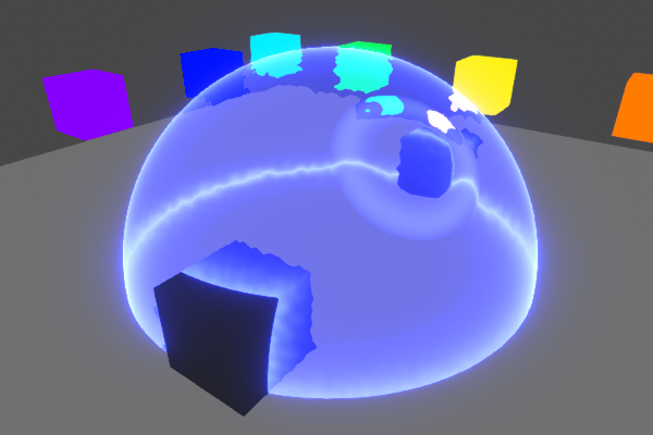
Hello. I need some help, terribly. I'm working on a shader for use in a scene with only point lights, but I get a square point light shape. They are very annoying and causing some delays in my work. Does anyone have a way to get around this? Please 🙏

I'm using Amplify Shader Editor, btw.
@subtle obsidian what do you mean by square light shape?
It looks like your lighting looks fine, looks like you implemented stylized lighting ramping.
Or did you do that accidentally?
If you look at the image. There is a nice circular falloff from the point light. But if you look at the top right corner, you will see the top right corner of a square, and outside that square is unlit.
Yes, I've done toon shading
maybe this shows it more clearly


I guess you broke the light distance attenuation curve and now it doesn't go down to 0.
well I don't want it to. because I don't want black outside the falloff radius.
Are you extracting the light positions and using them with your own attenuation curve?
This is what I use for light attenuation. It looks like a nice curve shape. But again, I don't want a black unlit color, and anytime I try to increase or remap these values to anything above 0 (black) the square comes back.


Also.. I don't think OneMinus works properly in this instance. In ShaderGraph, I would just OneMinus the light attenuation to invert this gradient, and use that as a mask to multiply a base color. But in Amplify it does not work as expected. If I use OneMinus on this output, I will get all White (1) which makes no sense to me
So I feel like I need another way
Well, think about it this way. If an object is outside of the bounding box of any light, what's going to make it match to the darkest color of a lit object? I think you need to have attenuation that goes down to 0 and add a constant ambient color to raise the floor. This way both lit and unlit objects will have the same lightness floor value.
I really dislike debugging visual shader graphs so that's as much rubber duck debugging I can do at a glance 😆
whenever I add color, I get the square though. like so.

the area outside the circular falloff seems to get more added to it.
That's kinda odd, can you post the generated text shader? Though if it's not for HDRP or URP I'm a bit rusty, been ages since I looked at builtin rp shader code.

It's BiRP
Ah. Birp does this outdated approach I think where it invokes a shader pass for each 4 lights?
I think Ive read something like that. each pointlight is a new pass through the logic
Maybe your custom lighting is going into that additive pass instead of the base pass.
i would love to learn more about not doing that
Could always write the shader by hand 😆
XD ohboy.
never done that
but I learned theres a Custom Expression node in ASE that can support code
I'm worried how much time it would take me to learn, vs when I need to have it done.
Well, you can at least check the source code for the generated shsder and see in which pass your ambient color gets added.
ok ty
Oh, also try adding the ambient to the albedo instead.
No difference it seems

No, I mean plugging a Color node to the Albedo slot. At some point you'll add colors to your shader and then you'll instead plug color + constant custom ambient color to the albedo slot.
And by plus I mean adding those two colors.
Albedo = mainColor + ambientColor
Ok. I tried this. Nothing changed. I have had issues with the albedo channel before. Just doesn't work. Emission works but it doesnt help me

Do you maybe know why the albedo channel does nothing?
i should expect to see blue but i do not. I learned this is because albedo is baked GI only

Ok I've looked at the shader code. If I understand correctly....
I see this LightingStandardCustomLighting get a +=
its in a function that starts like this
// fragment shader
fixed4 frag_surf (v2f_surf IN) : SV_Target {

In ASE, there is a Rendering Option that says "Add Pass" when I uncheck this, the point lit areas disappear (pic 1). Does this help confirm your assumption?


@subtle obsidian Use ambient lighting for the light color outside of any lights
It doesn't make sense that individual lights could control the lighting of objects outside of their influence
That produces squares around the point lights which I don't want.
Unless you know a way to do what you suggest without producing the square.
I don't necessarily want the point lights to light anything outside because so far as I know, it's additive and will lighten in an undesirable way
does anyone know how to fix this marching cubes compute file
me preview the file 👀
see massive lines of const of numbers
close
Nope, not me
Fix in what sense? Are there errors? Also !code:

Posting code
📃 Large Code Blocks
Use links to services like:
https://gdl.space/, https://paste.ofcode.org/, https://hatebin.com/, https://paste.myst.rs/, https://hastebin.com/
📃 Inline Code
Surround code with three backquotes. Not quotation marks.
To format as C#, add cs to the first line:
```cs
// Your code here
```
Add a comment with a line number if there is an error message.
hey yall on this shader this color isnt solid and its making it near impossible to make a hue shifter how would i make it so its a solid color?
and i also tried changing the A and it doesnt effect it its still a weird gradient. any ideas?


It's just how Unity displays HDR colors in the UI, internally it is a solid color, not a gradient.
Not sure if I should put this in the shader chat or coding chat but I am basically creating a mesh from c# and I want to have my triangles a singular color(for the low poly effect). Now I am guessing the way to achieve this is making sure three vertices that make up the triangle all have the same color but the result is not what I really hoped for.
My guess is the shared vertices that the triangles have, and that might be whats causing the issue but I have no idea on how to solve it 😔


You guessed right, if you share the vertices between the triangles you can't separate the color of individual triangles.
You'll need to duplicate the vertices
Ambient light would be applied before any other lights, separately from them
The lights then would only have black as the darkest color, so the darkest areas get lit only by ambient light
Then there can be no "square"
Any idea why this shader is affecting the pivot position? It suposse to be a grass-like movement


Shaders cannot affect pivot position
So, the shader is moving the vertices away from the pivot
Naturally. I've found that if the object in 0, 0, 0 position it doesn't affect vertices position
Is there a way to isolate only the objects behind a shader using depth?
I know I can compare depth values from whatever the screen is seeing with Scene Depth node, but I'm not getting the depth of the shader I'm doing the calculations on. The shader itself is transparent, and not included in the depth texture.
I'm trying to make a distortion-type portal, but I only want the stuff behind the portal to be distorted.
My idea is to use a branch and just take normal scene color instead of the distorted one if the depth is below the position of the portal-shader.
But my issue is to get the actual portal-shader fragment depth...
any ideas?
Either of these get the depth to the fragment being rendered
Position node View space -> Split/Swizzle "B" -> Negate or Absolute node
or
Screen Position node set to Raw mode -> Split/Swizzle "A" (though this one only works for perspective projections)
(in world/eye units, so would use Eye mode on Scene Depth when doing comparison)
Bit of an old tutorial but I use the same technique in this, in case it's useful
https://www.cyanilux.com/tutorials/water-shader-breakdown/
Both of these work the same way...?
well not the same way - but they yield the same result?
Assuming perspective projection yes. The latter one using screen position is more commonly used, but is always 1 for orthographic cameras.
hmm do you maybe know on how I can duplicate the vertices? I have spent some time now and I cant figure out a "algorithm" on creating the vertices that way and then sucessfully setting the triangles with the duplicated vertices. Dont know if you maybe have some experience with this
the code for the mesh https://pastebin.com/Kr4TeM7c
Pastebin
Pastebin.com is the number one paste tool since 2002. Pastebin is a website where you can store text online for a set period of time.
hey guys, I'm quite new to shaders, but I was wondering if anyone could tell me how to turn my fullscreen shader into an overlay? preferably with the ability to set its "alpha" to a value for different parts of the image?
I'm creating a blur shader, but what I would want to do is make it so only dark parts of the image are blurry

meaning basically the alpha in the blur overlay would be lower in brighter parts of the image
Well, you need to rethink your mesh generation logic.
You are doing a grid where each cell is two triangles. But share the triangles vertices.
Currently the vertex count is (density+1)² and triangles count is density² * 6 (number of triangles * 3)
Well, have as many vertices as triangles indices, and give each triangles unique vertices.
The end algorithm isn't that much different than what you already have, just have more vertices and some will have the same position as they are at the same grid position, but relate to different triangles.
So vertexCount would be the same as triangleCount? I am sorry, I am kinda lost here. I tried googling and seeing if anyone is creating the same effect as me but havent found any code or anything
Figure out a quad, made of two triangles, and 4 corners.
The triangle index array will be 6, 2 triangles * 3.
And because you want to have an uniform color over each triangles, you can't share vertices, so you need 6 vertices, 3 unique ones for each triangle.
So yes, on any mesh that is flat shaded or where you would paint vertex color by triangles, the vertex array will be the same size as the triangle indices array.
I'm unsure to understand the issue. Isn't the fullscreen shader enough ? Why (and what do you call) an "overlay" ?
Imho, simply sampling the color a first time before bluring to estimate the blur radius seems the way to go.
yeah you are definetly right, i should probably simplify my problem before I start dealing with thousands of vertices. I am gonna make the quad manually and from that figure out getting loops into . Thanks for your help!
How can i set #pragma target 5.0 for custom function in shader graph?
Is there a way you can get the additional light info in the shader code and do something with intensity and the texture2d? (2D sprite in 3D URP). Wait does it matter if I'm using 2D sprite or not?
AFAIK, you can't do this and I don't see any exposed setting for defining the target shader level.
nvm, I found it
I'm trying to create a blur shader that only affects dark parts of the screen, basically taking the entire shaders result and modifying its alpha so the alpha is weaker in brighter areas, and then layering that shader on top of the screen
Like I said, if you already have the blur shader working, you could just reduce the blur radius based on the darkness of the pixels.
I'm getting these glitches here and there, and the whole shader looks pretty uncomfortable and scratchy when the camera moves - and these artifacts between texels appear frequently

I'm guessing it's a floating point error thing?
Without any shader code it's impossible to tell what's going and and what's supposed to happen but the vertical line looks like some arithmetic error like division by zero
often happens for specific row of pixels with same uv value for example
Looking to try my hand at recreating this type of effect. How do you do this sort of layered 3D rendering? Stencil buffer shenanigans?
Probably textures sampled with parallax. In short, using the view direction in tangent space to offset uvs
You don't think it's broken into layers? The card text/elements are obviously just transparent sprite elements layered on top (probably), but I'm unsure on how the rest is put together. Could it all just be one shader on a flat card model?
yeah you don't necessarily need stencil buffers here. Just offsetting the textures based on angle would yield the same effect.
Mmm, Idk for sure. The background is likely parallax. But yeah it is possible the character could be separate and masked with stencil
Actually yeah looking closer that's likely. Parts of the character are even at different depths/offsets or angled it looks like (mostly looking at wings & tail)
Id say it would be easiest to just use parallax for the offsets. Only seems to be two layers in this case so shouldn't be too hard to use different depths for different parts
I mean parallax with the character seemingly in front and background behind the card. The text and such seems to just be slapped on top of the card separately
With actually different depths and stencils you may run into problems if you need multiple cards on top of each other
I am trying to follow a tutorial to fix my water refraction issue. They are using Amplify and some of the nodes are not in normal Shader Graph.
What is the Shader Graph equivalent to Amplifys Surface Depth node?
https://hastebin.com/share/vomidoboca.csharp
it dosnt create any triangles theres no errors or anything
Hastebin is a free web-based pastebin service for storing and sharing text and code snippets with anyone. Get started now.
Are you sure the issue is with the shader itself and not with how you dispatch/use it?
Thanks!
https://hastebin.com/share/zuwozobizu.csharp
heres the code the other parts are just other noises that arent important
Hastebin is a free web-based pastebin service for storing and sharing text and code snippets with anyone. Get started now.
I'd check that finalVerticies has the values you expect.
It also seems like you're basing off Sebastian Lague tutorial. I'd try to revert your changes to it until it actually works as in the tutorial, then add back your own changes one by one to see where it starts breaking.
What about the very back of it? Those sparkles of gold. Do you think that’s just a series of scrolling dot textures?
Looks sort of particle-like.
Also parts of the body don't even seem to be on the same layer.
Tail is under the border while wings are above.

maybe it's parallax with several layers, left foot on +3 layer, head and body +2 layer, wing and right foot on +1 layer, frame on 0 layer, and tail on -1 layer
im starting to see something thank you very much but its still glitchy some so i still have to work on it but thank you for the help
Hey guys I have a shader and i want to Include options to enable or disable the effect for different sprite states (e.g., hover, selected).What is a good way to do that?
I am working on a game, this bullet has a shader assigned to it, there are no light sources in the game , compute shader is used for that, now i want to add glow to the bullet as if its glowing when its dark can this be achieved solely with shaders without light sources, I am using built in rendering pipeline, if yes then can someone guide me where i should start

- You need to understand how glow usually works : Glow in the general use case is a post process that "bleeds" pixels of high intensity to their surroundings. So it is not somethings that individual object do, but an overall screen effect. Most of the time this is done using the emission property of lit shaders, or by having a high color value (higher than 1) on unlit shaders.
- In some cases, you can fake glow by using some transparent object with an additive shader
- Glow never lights other objects. That's what lights are for. For high intensity objects to actually light their surroundings, you need global illuminations. Baked for static objects, or realtime (SSGI, Raytraced GI) for moving objects like your bullets.
So, in the context of the built-in pipeline :
Simple solution : add emission to the shader or increase the output color value, and add a glow post process effect
If you want them to light other objects : add an animate a lights source, or use realtime GI.
So I have an issue. I'm trying to create a sense of parallax. The problem is that when I set the offset to be "closer" to the camera, the texture suffers from distortion if the camera physically gets close enough.
Parallax when farther from camera.
Parallax when closer to camera.
This is the shader logic.

I'd obviously like there to be no distortion, but I'd also like it if the texture suffered no change in apparent size.
The goal is to create a faux parallax, something similar to this.
iirc you need to divide the viewDir vector by it's own Z
I'm assuming this distortion occurs because the view direction operates on a per-fragment basis, and the angle across the image gets bigger as you get closer.
Interesting.
Is there a way to prevent it from changing apparent size?

Noticing some oddities around steep angles. Makes sense why that'd happen.
Instead of the viewdir, you can use the camera forward vector (direction), transformed to tangent space, if would do an "orthogonal" offset.
Or have a mix of both to controll the apparent size.
You coudl also try the "Parallax Mapping" node 😄
How would I convert the camera forward vector to tangent space?
"Transform" node
oh, hmm

Uuh this or do I set the type to direction? Sorry for blasting you with questions, haven't messed much with camera trickery.
The direction is in world space.
So you need to transform from "World" to "Tangent" and indeed set the type to "Direction"

I think that's it?
Yup
When using the "view direction" node, as you've mentioned, the value is per pixel (it is camera position - pixel position, normalized). So when looking from close up, the vector goes away from the center of the screen, resulting in a zooming effect.
But the camera direction vector is a constant vector over the whole screen (it is the camera transform forward vector), so it uniformly shifts the UVs.
I understand that part. What's more of a mystery is why this vector, in tangent space, results in this shift.
Try to visualize it in 3D at the surface of the quad. The camera vector goes "underneath" the quad when you look at it.
In tangent space it as some X&Y value, and a negative Z.
But since your are applying it to the 2D uvs, the Z componend it ignored, and an uniform XY offset is added to the UVs.
Oh so it's sort of like, there's a unit sphere formed around the current UV coord.
At any given frame, we use the camera direction vector to get a new point along this unit sphere, which is then projected back on the XY plane because we ignore the Z.
Offset is used to modify the radius of this unit sphere and simulate farther distances.
Right?
Ooooh and we switch to Tangent space so this XY contribution aligns with the UVs.
Fucking shaders bro.
It's just linear algebra and trig all the way down.
Yep, always 🙂
Thanks for the help and explanation, appreciate it.
Does this type of parallax have a name even?
Probably, but I don't know it :p
Orthographic parallax? I guess?
🤷♂️
This seems to work nicely at first but it's hard for me to believe this would be the mathematically correct way to simulate it as if the texture was at different distance. Especially when you are close to the quad and rotate the camera (without moving), the texture seems to move a lot even though it should stay at the middle of the quad
I think you should actually use the view direction in tangent space and do some simple math to calculate the right uv shift
I have a bunch of shader properties in groups on my blackboard that I want to copy into another shaders blackboard... Is there a way to do this?
Copy/paste should work
Why should it stay near the middle when close?
If you are at the middle of the quad it should right? And rotating the camera shouldn't move it relative to the quad right?
let me show you
thanks for this. On my end it seems what's happening is that the copy and paste will fail (do nothing) if there's a category in it. but I guess I can just recategorize them
Ah yes, I think it can be tricky indeed. IIRC, you can copy/paste properties but not the categories, but you can paste in categories. So if you create the category in the target graph first, you should be able to paste properties in it when it is selected.
that's not working either on 2022.3 but I'm close enough thanks again
@steel notch @amber saffron I miraculously got my maths spot on the first try too 🎉 . Let me show how mine works. I also added an actual sprite that I enable in the video to show that it matches exactly what it is supposed to look like if it was a sprite behind the quad (also works for negative distances meaning it would be in front). The math also simplifies to only couple very cheap nodes too.

I swear I had this earlier.
#archived-shaders message
I didn't realize you actually did. but that's what you are supposed to do no?
Could it be that in this video you had a "negative" distance, making it so that the image is projected toward the camera. If would easilly explain why it looked like if it was scaling up when looking up close.
it would. Still the apparent size would slightly differ but that's what's supposed to happen in parallax mapping
I did yes, but I do want some elements to be "in front" of the quad.
Here for example, charizard is definitely moving as if it's infront of the card.
#archived-shaders message
I think it is very slightly in front though
And if it was in front, it should scale larger when you move closer no?
This method shows the image exactly like with the stencil method discussed earlier
With the character only slightly above the card surface it would likely look very similar to the example provided
The View Direction solution seems to not like it when you get too close 😛
You are behind the texture at that point
That is when the camera goes under the "virtual plane" where the iamge is projected.
Assuming something flips when the camera distance becomes smaller than the simulated distance.
Ya.
You can just make sure it hides the texture when the distance is smaller but I don't think you want to go that close to the cards anyways. The character seems to be very slightly in front of the card in the example footage, not like one card length away like in this one, more like 0.1 card lengths
Hmm. I'll stick to yours for now. I do sorta like the concept of being able to keep the apparent size. It's nice making sure the art is scaled properly.
If you want to change the parallax you gotta mess with the tiling this way.
I get that but luckily the size change isn't that noticeable when looking at the card from larger distance and the parallax offset is relatively small. I think the problems with the camera direction moving the card could also become a problem at closer distances
There could also be some middle ground between these two
Anyone know why my Graphics buffer does not show up in renderdoc ?
In what context is it being used and how are you looking for it?
Im declaring and giving it a name in c#, then setting it as a global buffer. Im looking for it in the resource inspector
Unity will only bind it if a draw call requires it, and it will bind it at that point.
Hmm a shader does use it. But the resources inspector does not change between events…
I never use the resource inspector. I just check the resources in the relevant events.
How could I get the pixels behind a mesh in HDRP, like how grab pass works in BiRP, I need it for an atmosphere shader
My thinking is that since Im setting it as a global buffer it should be bound even before the draw call
So I did find the buffer but it does not have the name I set it for some reason 😦
shadergraph has a scene color node
yeah IK, but it doesn't exist in shaderlab, and I need it there
Just look at what the shadergraph compiles to. I don’t remember how to sample the color buffer unfortunately.
The node uses macros, which are defined in https://github.com/Unity-Technologies/Graphics/blob/master/Packages/com.unity.render-pipelines.high-definition/Runtime/ShaderLibrary/ShaderGraphFunctions.hlsl
so I could just call shadergraph_HDSampleSceneColor to get the same effect?
If you use that include, or could copy the function/body
Hello, I am having a little trouble with a vertex shader I made for an ocean. Specifically I am having trouble with the normal map displaying correctly compared to the video I am using as a starting point. I have deliberated for a day trying to figure out why it's broken and I can't figure it out. I am using URP on unity 2022.3.47f1
I can show the video, what it's supposed to look like, and what's wrong if anyone can help
Yes, that is information we would require
Should look somewhat at least like this, but instead looks like this. I know my planes have less vertices than his, but I don't think it would cause this
Here is the video I was following:
https://youtu.be/QAH1Kep3zRM?si=PNqoz0UCw_9Y9x9w
around 26:46 is where I am, I have some normal maps I'm using for noise across the surface but I cannot get the basic part figured out so I turned it down


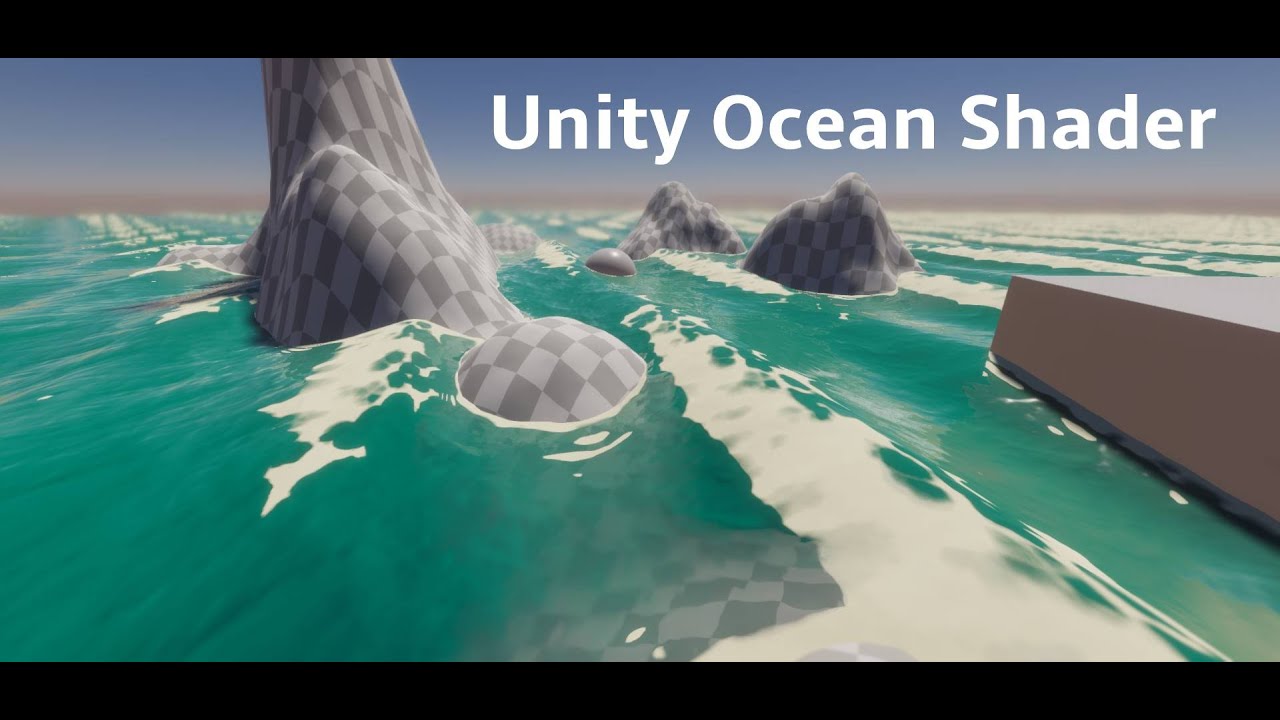
I've been experimenting with shaders a bunch recently, and wanted to showcase some of the techniques I used in this ocean shader. It's my first tutorial, please be gentle.
00:00:00 intro
00:02:01 shader setup
00:03:17 wave generation
00:15:44 secondary sine wave
00:20:14 normals
00:28:00 edge foam
00:42:57 wave crest foam
00:45:40 desmos graph
...
this would be the part I am having trouble with atm, even if I pull from what I put into that vector3's y value instead of what I currently have it still does the same thing

by that I mean this, it hasn't made any difference

it is probably something stupid that I just don't know yet as I am learning unity, but if anyone needs more info I can provide it
hey did you find a solution for this ?
or for this. I have the same problem
Looking for a impact collision shader on sphere with a wave or custom noised dissoleved effect on it. What i find around is kjust a simple circle on collision.
Having an issue where when I blend a texture, I get these dark regions at the border.
I assume I'm fucking up the alpha

Could be caused by many other things too. All basic arithmetic is pretty fast on GPUs, I don't think any of the nodes are particularly expensive, the most expensive would be texture samples which aren't really that expensive either
Thanks.
Texture samples in terms off? Could you please explain more about it?
will the sampler state work?
The Sample Texture 2D node, I'm not sure what you mean
oh! got it.
I understand something else, I got your point. I think I have to add one more node that is sampler state.
maybe that will work.
The texture import settings are used if no sampler state is defined
I have already sated textures setting as per the mobile.
You should use the profiler to troubleshoot performance, rather than making random guesses.
you are talking about unity profiler or any other profiler, like snapdragon?
Start with unity profiler to identify the general direction of the issue.
It shouldn't have any impact on performance, but what is the point of the branch node where the predicate is always true ?
I will add the property to turn it on/off.
any one how how to make cross section shader graph
Yes
can u guide me
I don't know what kind of complexity you need but as of now I have created this, I hope it will help you.

what is this inverse(B) ?
you want to cross section from top or bottom.
bro this is not working i tried

bro what i want is i want expose inner texture as well so that it look like a solide mesh

it is currintly hollo mesh i want this type of behavior

Has anybody have a shader or does anybody know how I would create a "censored" / "pixelated" local shader which I could attach to a plane or other 3d object to pixelate everything behind it? Ideally in shadergraph and HDRP.
oh! got it
can we cannect if u wana help me in this topic?
DM me
I think that's usually done by rendering the back faces as if they were flat at the intersection. With shader graph though you will run into problems with shadows/reflections/lighting/SSAO/you name it because you can't change the apparent pixel positions in fragment shder. Now that I think about it, there might be a way to actually project the backfaces into the intersection plane in the vertex shader and keep only the relevant parts in the pixel shader but I'm not yet sure how exactly that would be done
With custom interpolators at least you should be able to keep track of the original position before projection to the intersection plane and use that to cull the pixels based on depth
If you change the normals of the backfaces to match that of the clipping plane it shouldn't look as hollow
Remy also has an example that creates texture coords #archived-shaders message
Hello, How can i add a normal map to this shader ?

Wouldn't that alone cause the lighting issues I described?
Maybe, better than nothing though
Like shadows that get inside the intersection/box reflections/screen space effects etc.
Haven't looked into Remys solution, the demo looks cool at least
Hey everyone, does anyone know if there is a way to make a general lighting (like the sun) in Unity work in per-Vertex mode instead of per-pixel (like you can do with dynamic point lights)?
Hi guys, How can i use Standard surface shader with HDRP ? because its actually pink
Alright I'm confused about something. I have a shader here that just combines 2 textures through a lerp. Here is the result and the shader. The top layer has a blur to it, so it's semi-transparent along the border. For some reason, this border region appears darker than you'd expect.

This is the result that I want, and I can get this using the follow graph, but why does this work but not the other?

Is there something off with the alpha channel? Some pre-multiplication?
When using that Float (1) output into that Multiply (4) input, the float is "promoted" to the same size - it makes a Vector4 filling all channels with the float value float4(alpha, alpha, alpha, alpha)
While when you are using the RGBA output, the RGB data stored in the texture is likely just 1
Yes, that looks like a premultiplied texture. The transparent pixels are black instead of white.
Oh but over the alpha it's actually increasing. So during the lerp, in the semi-transparent regions, I'm lerping between the background color and some value between 0 and 1, not white, which is making it appear darker.
Cyan is right, I didn't look at the graph closely enough before answering.
All good. So wait though in the actual image file itself, what are the values in the completely transparent, semi-transparent and fully opaque regions? Is it...
- Opaque: (1, 1, 1, 1)
- Semi: (1, 1, 1, 0-1)
- Transparent: (0, 0, 0, 0)
?
Ok I just pumped the R,G and B directly into the output.
And it's all white.
Depends on the texture and how it was exported and imported... 😅
All the channels are 1 across the entire image.
Except alpha.
Yeah, that's what I expected based on the results above
So once I bring in a colored texture and just show the red channel, obviously we see the red contribution, but there's also these messy regions surrounding the art. What are these?
I'd assume the texture is imported with the "Alpha Is Transparency" option ticked - if you hover over that the tooltip should explain iirc. It expands colours into fully transparent areas to help avoid artifacts
The rest might be from the texture data itself
Okay, I'm kind of stupid, how exactly do I do that, because I have added/copied shadergraph_HDSampleSceneColor into my shader, it just returns the default black color. I have also added #include "Packages/com.unity.render-pipelines.high-definition/Runtime/ShaderLibrary/ShaderVariables.hlsl". Is there something else I have to enable?
Sorry for blasting with questions. Why is it like this then? Is it some result of png compression?
Like creating repeating regions to save on space?
I'm not familiar with how the png format actually stores data so not completely sure. But I'd assume it's just the program that exported it in that way. I know GIMP for example, has a "save colours in transparent areas" tickbox when exporting to png. When unticked (which is the default iirc) it might stretch out like that
Might need #define REQUIRE_OPAQUE_TEXTURE and #define _SURFACE_TYPE_TRANSPARENT as it checks for those in the function
Could be easier to just use return SampleCameraColor(uv) * GetInverseCurrentExposureMultiplier(); instead
yeah about that: Shader error in 'Hidden/RenderSkyMesh': undeclared identifier 'SampleCameraColor' at Assets/PlanetaryTerrain/Graphics/Shaders/BrunetonsImprovedAtmosphere/RenderSkyMesh.shader(281) (on d3d11)
doesn't exist apperantly
Then another include is probably needed
I'm just wondering which
Hmm, alright just one more question then. I've noticed that a lot of textures in VFX tend to just be completely white and black, this includes masks. Why not use the alpha channel?
I already defined that though
Like for example, Unity's default particle.

I guess you can use it for other stuff then easier, like multiplying it with a color to get a fade out or something
Might be to save space, as that could be imported as a single channel texture rather than full RGBA.
But I think those textures are "premultiplied" like MentallyStable mentioned earlier. Meaning it would create a darker edge even when using the RGBA output
In these cases I'd probably use the texture only in the T input and just a color property in the B one
Ya this does it.

Is that line before where you're using the function?
yeah, it's just after pragmas
Hmm not sure why it wouldn't work then
yeah me neither
Oh well I'll sleep on it and keep banging my head against a wall tomorrow
check this out
even this
Hello, is anyone there avaliable to help me calculate coords for my skybox?
It's a very strange issue- but it should be simple to fix (Just not smart enough to fix it myself lol)
Using a modified built-in skybox, I've created this function which is supposed to project a texture unto the sphere:
{
    return float2((0.5) - (acos(dir.x)/2), (0.5) + (asin(dir.y)/2)) / size;
}```
When it's called:
``tex2D(_MoonDetail, projectImage(-ray + _WorldSpaceLightPos0.xyz, _MoonSize));``
``ray = normalize(IN.vertex.xyz)``

This accurately projects an image onto the skybox! Well, expect when the sun is around ``-90`` or ``90`` on the y axis, it starts to stretch... I've discovered that this fixes this, but presents the same issue but for the other axis
```float2 projectImage(half3 dir, float size)
{
    return float2((0.5) - (atan(dir.z)/2), (0.5) + (asin(dir.y)/2)) / size;
}```
I was trying to merge them together, but no matter what I would do it would make wacky results:

```float2 projectImage(half3 dir, float size)
{
    return float2((0.5) - ((acos(dir.x) + atan(dir.z))/2), (0.5) + (asin(dir.y)/2)) / size;
}```

I'm so close yet so far to getting a moon texture on my skybox, and if someone would help me how to normalize each value out, I would GREATLY appreciate it!!Does anyone know why whenever I double click the .shader file or .hlsl file (in Unity Editor) it always opens with VSCode but not Rider? I can open the C# file with Rider when double click but not .shader and .hlsl
Yo, Im trying to get a shader graph that uses Main Light Direction to paint shadows but not per-pixel as by default, but instead per-vertex. I am using a URP Unlit shader as a basis for that, but... is that wrong? Don't I need there to be a Color node in a Vertex block?

You can right click and add a custom interpolator
https://www.cyanilux.com/tutorials/intro-to-shader-graph/#custom-interpolators
Oh dang, thank you!
Man linking his own website is such a power move.
it is rather useful tho. I remember visiting it before, and after a while I often find myself looking for something that this site has
Fog Plane Shader and an article about Depth are a must have
it kinda pisses me off a bit that when you google for these things - you mostly get results from reddit, unity forums or youtube
but there are a lot of blogs/sites like this that might have exactly what you need, but they don't show up as much
okay when I get paid from the games I put out - this fella is getting something
Okay, I was trying to blindly get this thing to work, and I ended up in an Unlit shader that includes:
- Vertex Shadows which were painted onto the model by hand as Multiply blend
- Normal Shadows from Global Illumination
- Ambient Light that lights up the Normal Shadows from global illumination
- Inclusion of the scene Fog that blends as a Screen blend
The problem is, Im plugging it all into Fragment Base Color, sooo, even though Im calculating shadow from comparing surface normals with global light direction - I don't think it's actually vertex-based shadow, so now I have to read up and figure out how to plug the same stuff into a custom interpolator

So I have a shader that I'm trying to convert to HDRP from Built-in, and I'm at the point where I would need what's behind the mesh. Now I wanted to use scenecolor for this, but I just can't get it to work, as It says SampleCameraColor isn't defined. But in it is how it's defined in the shadergraph files right here: https://github.com/Unity-Technologies/Graphics/blob/master/Packages/com.unity.render-pipelines.high-definition/Runtime/ShaderLibrary/ShaderGraphFunctions.hlsl.
Does anyone have any idea on why it isn't, or where that function is actually defined?
https://pastebin.com/LD03d8Ti here is the relevant code (the part of interest is at the bottom, line 282)
Pastebin
Pastebin.com is the number one paste tool since 2002. Pastebin is a website where you can store text online for a set period of time.
How do I make a Canvas Shader Graph maskable?
Apparently just adding a new float named Stencil did the trick
Hey @regal stag
considering the force shield here: https://www.cyanilux.com/tutorials/forcefield-shader-breakdown/
Is it possible to have better impact like this in the image?
The impact we have on that shield is just a simple circle. I would like to see something with a mask texture for the impact, so that I can custom it as I prefer with an alpha mask and not just a perfect circle. is it possible?

A forcefield shader using fresnel effect for glowing edges, scene depth for object intersections and scene colour to produce ripples/distortion
and is it possible to make it work with hdrp?
hope you can help me. Thanks
What reason might there be for one of my shaders being missing from build? It simply highlights some objects. It works as expected in editor but in build the objects become pure purple when highlighted by the shader
did someone ever give this a look?
Purple doesn't necessarily mean missing shader. It could be an error or render pipeline incompatibility.
Make sure the build uses the same quality settings level as the editor.
The color from an Image doesn't match what is rendered in the game when using a canvas shader graph. This is most likely due to my game being in linear color space. Any idea how to convert the color properly within the shader graph?
There's a Colorspace Conversion node though I'm unsure if you'd need to use it in this case. Might just need to adjust how the texture is imported?
I wasn't using any texture, but I think I was doing something wrong in the shader overall, I wasn't using vertex color as I should've
And tried color space conversion too and yeah it wasn't the answer here
Using a mask texture would be possible but not sure how you'd calculate the uvs to project it along the ripple direction atm, and might be a bit expensive anyway as you'd be sampling for each ripple.
Adding some noise that is mapped to the shield instead should be easier to make the ripples less circular. e.g. sample noise in graph, Multiply by 0.1 and pass into custom function, add to 3rd param of smoothstep I think should work
pls help. Material is working on cube but doesn't working on my model

It's likely that your model isn't UV mapped
Thank you!
Using ShaderGraph (Unity 6, URP) is it possible to have self shadowing in a custom lighting shader? (base shader is unlit)
Petition to rename this channel Cyan-Support or Ask-Cyan 😄 The amount of help you give the community is insane. Unity should pay you.
I don't suppose there's any way of doing some kind of each-eye-different processing in shadergraph whilst still using single pass/multiview VR mode? I'd love to be able to do even something as simple as something like if left eye +1 if right eye -1 , but I can't pay the performance overhead of multipass VR for it
You can copy the lighting code and the shadow passes from the default URP lit shader
It's a bit tedious but can be done
You'll need to search in the #include-ed .hlsl files
Hopefully we get block shaders soon so we don't have to mess around like this for long
Also, if you're using a "CG" shader you'll need to make it into a HLSL one by replacing ENDCG with ENDHLSL and same with BEGIN or whatever it's called. Also the base Unity .cginc won't work
you'll need the Core.hlsl include at least in your shader
check "unity_StereoEyeIndex" to see which eye you are rendering to in your shader
I'm guessing 0 is left 1 is right
ooooh, and I guess this is that

yea
super nice, I didn't know we could get this, thanks!
I was about to suggest hlsl blocks, didn't know eye index was a default thing
no problem!
I got a quick question about shader variant compilation for builds: Each pass of pretty much any shader being compiled is taking about 2 full seconds on average, which I feel like is way too slow. Any tips to speed up this process? I have stripped pretty much all the variants I can, I'm just trying to see what I can do to speed up the time it takes to compile a shader variant. Unity is using 100% of my cpu to do this
I'm using an intel core i5-8400 with 24gb of ram
Is there some way to do color replace on these colours with shader graph?

so i can make chromas easily?
how can I add some code to the URP Terrain Lit shader vert's function? I am using unity 2022, but if I go to the Packages/Universal RP/Shaders/Terrain/TerrainLit shader code, tehre's no vert function
anyone know y the specular seems inverrted on my water?

How to make a canvas shader additive?
I'm trying to achieve a good TV scanline animated shader, but so far I just used a mask recycled from a hologram shader.
Can somebody suggest me a good tutorial/guide to achieve it?

nvm just found Cyan's amazing shader
Thanks man 🙏
is it possible to make a tree sway in the wind with shader graph? I know how to do that for the leaves with vertex manipulations, but how about the tree trunk? I assume swaying trees arent made through skeletons or rigging, cause that would be insane, but what about shaders?
I know Unity used to utilize SpeedTrees, especially when used with Unity's terrain and windzones, but as I understand SpeedTrees are now deprecated? or outdated? or whatnot?
Why does Rider not recognize that my Shader Graph shader is a valid shader when finding it via Shader.Find I've added it to the project to the always loaded shaders already.
It's a problem because then I can't set properties.

You set properties through the material.SetFloat, SetVector, SetColor, SetTexture etc functions
Ah I see, thanks!
Though it may be easier to create a material asset and use a public/serialised Material field and set from inspector rather than setting properties through code. That also ensures the shader variant is included in the build, which doesn't happen with Shader.Find
Yes I saw the docs on that, so for the moment I added it to my project settings to always be included.
Speedtree is not deprecated, is now uses shadergraph to handle wind sway for hte two new render pipelines.
Usually, the trunk/branches sway is the same logic as the leaves, but you add a "weight" to the model usually through vertex color or UVs.
The very base of the trunk has a weight of 0 to not move at all, and the finest branches have a weight of 1 to stick to the leaves.
Oh! That's great! I thought I ran into a block when I was trying to figure out speedtree stuff, but... I'll have to take another look. Vertex Color... Vertex color... That might work, that might work even without a speedtree, if I can reconstruct the shader graph. Thank you!
it it true that every shadow rendered using indirect instacning is drawn in all 4 (assuming thats the setting I have) cascades, no matter how far it is located from a player?
Thanks for the reply Peter, I found everything in the ShaderLibrary folder of the URP package
Also for future reference the ShaderGraph package has new examples including custom lighting
Hi, I have a lot of skinned characters (150-300), and I'd like to fade in a damage/blood texture on them as they get hurt. Not decals, just an overall texture that covers them. I'm on 2022.3 URP, what is the best way of passing in a single value for each entity to describe the amount to blend in this texture? Are there ways of doing it without breaking batching? I heard that MaterialPropertyBlocks breaks batching in URP, correct? Thanks!
You can use material instances
SRP Batching doesn't need to worry about breaking batching
Right, that's great. Thanks!
This may be a #archived-urp or #archived-hdrp question, I don't know that part of the pipeline off the top of my head.
It would be pretty silly tho if that was the case
I'd imagine the renderers are culled per cascade
are you using "Graphics.DrawMeshInstancedIndirect"?
In there you need to add a "Bounds" property
that bounding box will most likely control which cascades your objects are drawn into
So if you go around making an infinitely big box they will probably indeed be drawn into all cascades
anyone know how to define a cubemap property?

Needs {} at the end
i think I tried that but ill try again
oh lol I was missing a semi colon later in the code and got confused, thx
sorry do u know if I can fix this?

I'm trying to render a camera pointing at the sky into a skybox cubemap texture
ah nvm im just going to use a static image for now
Hello hello! Coming here from a halftone shader tutorial :)
I'd managed to get the shader graph set up with no real fuss,
but when it came time to apply it to the scene, no lights seem to affect it just like any standard unlit shader graph
Currently working on trying to figure out how to integrate the additional lights (not very well versed in shaders in general) to see if that will help, but if anyone has any advice that would be helpful :)
Currently using Unity 6 for the project if that's helpful at all
Will be sending images of the shadergraph and subgraph shortly
https://www.youtube.com/watch?v=3iZrZrEWQuA
The tutorial that was used

Halftone is a technique used for printing where tiny dots of different colors and sizes are layered to look like a full-colour image. In this video, I use Shader Graph to implement a similar technique, where the shaded regions of the image are converted into differently-sized darkened dots.
👇 Download the project on GitHub: https://...
The shader graphs (The smoothstep connects to the final value of the Lerp node like in the video)


test cubes :)
No shadows being cast on the unlit normals

if unity's shader was built in shadergraph, can i somehow add billboard feature to it? or modify how billboards look? or is it not done in shadergraph but somewhere else
my shaders are not compatible with unity's bilboarding. so i assume i either need to modify the tree's shader (shadergraph) or how billboards work. idk which
@regal stag Doing some research for my own shield shader I came across your post and tried to adapt your ripple code into my own. It works but I can't for the life of me figure out how to change the speed of the ripple. This is the custom func I currentyl have ``` float t = 1 - _hitsBuffer[i].w;
float dist = distance(Coords, _hitsBuffer[i].xyz) ;
float3 sphereMask = 1 - saturate((dist - Radius) / (1 - Hardness));
float rippleSize = 0.07;
float gradient = smoothstep( 0, t, dist / rippleSize);
// float ripple = saturate(sin(10 * gradient));
float ripple = frac(gradient*3);
float3 rippleDir = normalize(Coords - _hitsBuffer[i].xyz);
float rippleStr = _hitsBuffer[i].w * ripple;
dir += rippleDir * rippleStr * 2.2;
// dir = floor(dir * 32) / 32;
str += rippleStr;
OUT += sphereMask * _hitsBuffer[i].w;
life = t;
iirc the "speed" is controlled by adjusting the radius (w component of hitsBuffer) so would be handled on the C# side rather than in shader
ohh my w of hits buffer is the lifetime of the hit
Oh maybe I changed it so radius is fixed and w is lifetime, either way that's still what controls the speed
right I need to redo the ripple then I think
anyone used the new canvas shader graphs?
You'd better directly ask your question.
I am trying to make a typical stylzied water shader for low poly game. Problem is that this game is gonna use orthographic camera which will not render properly foam and depth which uses screen position and scene depth. I thought it may be possible to have 2 cameras, one orthographic to render whole game and one perspective to render only water, but I am not sure how can I combine those 2 cameras to make them both render things at the same time. Or perhaps there is a simpler solution that someone might have?
Depth based foam can work in orthographic. Instead of raw Screen Position, try Position node in View space, Split B -> Absolute
And Scene Depth should work fine in orthographic. Unless you're on versions older than 2022.2 - then you'd need to use raw mode and convert to eye units, I have an example in a foldout in this post
got it, thanks a lot
Can someone help me? I created this simple Shader Graph in HDRP to generate an outline. The outline appears in the editor, but in-game the camera doesn’t recognize it.


Why are you multiplying the position by the exposure ???
(also, this shader works for simple shapes like the sphere, but for more complex shapes you probably want to use a normal "push" deformation)
I was just testing combinations with some of my other shaders, and this one ended up working (at least partially). I'm really not very good with shaders.
How can I do this?
output position = position + normal * "scale"

When you say (normal * scale), do you mean the normal vector and the float scale, multiplied and then multiplied with the position to get the output?
like this

I got it!
Thanks @amber saffron

hey im trying to add simple triplanar projection for my cave game but i keep getting this pink texture, its the first time i use shadergraphs i got URP installed but still no solution


does anyone know why every so often (like every 4-5 domain reloads) a shader I use for a decal (it was the default package one before with the same error) happens to hang unity having me to force close it?

regenerating library cache didn't do anything
Technically, there shouldn't be a shader reload on every domain reload. That in itself sounds like a problem.
yeah it comes uninvited
I'd have a look at the editor logs and make sure that the project is not in some place that might cause read/write issues to unity.
alright so I have an outline shader that uses a roberts cross to get the difference between the depths/normals surrounding a pixel. But that equation always returns positive values, so it can't tell if the difference is greater or less than the sampled pixel. This means that the outlines double up when inside the object or if multiple objects are layered over each other, which looks inconsistent and janky.
What equivalent can I use that lets me tell in what direction the difference lies?
I want to ensure it only draws the outlines for a pixel if the surrounding depth is deeper, or the normal is angled more away from the camera, instead of pixels on both sides of a change trying to draw the normal themselves
Also, in Shader Graph is there a simple function to convert a 0 - 1 range to a -1 - 1 range, or shall I make a subgraph for it?
And what happens if you try to lerp between two Vector3s, using a third Vector3 as the parameter?
Probably a compile error.
I don't remember if there's an inverse lerp node, but if there is, it should work that way.
oh yeah duh I can just lerp between -1 and 1 using the 0-1 value
although I don't know if that's more or less performant
maybe it doesn't matter, but I'm also trying to learn here
Probably negligible difference
I'm working on a circle wipe fullscreen shader, but having some trouble with positioning. I'd like the circle to be perfectly round in all resolution and aspect ratios, and also be perfectly centered. Here's what I have so far:

I can offset the center point using the Distance node, but I'm not sure how I'd go about getting it centered for all aspect ratios
I just made a new project and imported some assets, the project is urp and the asssets sa they support urp yet are all pink?

Seems like you're missing the shader.
ah wack, I just imported the asset. Do you know how I can find it
Inspect the asset contents. Does it contain any shader files? Can you share a link to the asset?
I will check, here is a link - https://assetstore.unity.com/packages/3d/environments/gothic-megapack-271511

Elevate your workflow with the Gothic Megapack asset from Meshingun Studio. Find this & other Environments options on the Unity Asset Store.
Got it in a humble bundle
it does contain shader files

and its weird some of the assets work
but then all of the modular ones dont
ah manually setting the asset to that shader works
and then finding their material
gonna take a little bit for 500 assets lol
Possibly they made a mistake when setting up or uploading the package.
also thanks @kind juniper for the info
anyone know if u can use RWTexture2D in hlsl URP shaders cause I cant geet it to work
Im seeing conflicting information online about the range of NDC position values. Is it from -1 to 1 or from 0 to 1?


I'd test by sampling the value and writing the X and Y values to values on a returned colour struct. If it's 0-1, the colour spread should go across the whole screen, if it's -1 to 1 then the colours would start at the centre and go to one corner
I don't actually know either, but that's how I'd try finding it out
I was looking at the new shader graph canvas with procedural shapes now possible, but I don't know how to use corner radius of a fixed size (not proportional). Seems you would need to add a component to pass size info from a RectTransform on an Image to the Material shader
But even then if it does nto nine slice it won't even work!
It would have different values depending on the graphics API. There are many differences between the graphics APIs. By using the engine provided API, you can usually ignore these differences and rely on the engine documentation instead.
You should read OpenGL and DirectX documentation directly. OpenGL uses a (-1, 1) range, DirectX uses (0, 1).
Can you make an array of colors as a parameter in a shadergraph?
My outline shader is turning out pretty well, except that the outlines become thinner and disappear the closer the camera gets to the model. The code in question compares the dot products of the normals relative to the view direction, and draws an outline if the difference is above a certain threshold.
I tried multiplying the threshold based on the camera distance (so the closer the camera, the lower the threshold to decide to draw the outline), which is better, but some of the outlines still disappear when I zoom in. Is the scene depth not calculated linearly or something, e.g. due to the camera perspective?
Here are the 3 methods I tried for getting the camera distance, in case there's some difference I didn't notice:
- Getting the scene depth with 'eye' sampling (raw produces even more artifacts)
- Getting the scene depth as a 0-1 value and multiplying by the camera's far clip plane
- Getting the view direction in view space and isolating the Z value
- Calculating the world space distance between the sampled position and camera position
I also tried lowering the threshold globally, but that creates fuzzy artifacts all over the model, so I need to be smarter about it.
alright it might be partially based on perspective. I tried setting the scene camera to orthographic and the effect was lessened. With both the orthographic camera and the distance modifier, the outlines barely changed with the camera distance
do custom render textures and custom render texture shaders work?
Just as a simple test I'm making a shader graph custom render texture shader/material ouputting a colour and then assigning that in the inspector, but nothing changes in the render texture preview window
the material updates in the preview window
Yes, in perspective projection depth scales non linearly, I recommend reading up on that to avoid further confusion. It's also reversed on some platforms. Raw depth is non linear depth coming up straight from the depth buffer. Eye depth is linear depth converted to worldspace meters so it's basically a distance from the camera in meters.
any good resources you'd recommend? Because I tried searching for that stuff but I didn't get much out of it
learnopengl.com probably covers it.
OpenGL has the best resources for theory, Directx only has like the rastertek tutorial series and that's about it.
@warm moss cheers thanks, I'll probably look at it tomorrow once I'm better rested
actually one more thing to ask before I go to bed, is there any disadvantage to changing a material's input values many times per frame? I've been brainstorming how to pass script data into a custom buffer, and I realised I could use a global material, then iterate through a for loop for each renderer, and before rendering change its values based on whatever data I want to glean from the current renderer in the loop.
I'm setting up a ScriptableRenderPass in URP
this is for a separate shader to the outline one I was talking about earlier
You're doing an "hull" outline, right ?
From what I remember of some hull outline shaders, the trick to have a constant line width is to :
- transform the normal to clip/screen space
- normalize it
- apply screen ratio if necessary
- multiply by line width
- transform back to object space
- apply the hull offset
nah I'm doing a sobel based thing
I do also have a hull based outline (for a different purpose) and that's turned out pretty well, except for finding a balance of depth threshold that ensures no part of the rear pokes through to the front, but none of the outline is cut off because there's an object too close behind it
If each object isn't using a separate unique material, this isn't going to work. Rendering isn't synchronous so if you want per object data without unique materials, you'll have to use a material property block that you either set on the renderer or pass directly if you use Graphics.DrawMesh/Graphics.DrawRenderer.
I just closed that project, but I believe I was going to use the CommandBuffer.DrawRenderer function
I know there's a separate function for drawing all the renderers at once under certain culling/drawing criteria, which obviously doesn't allow for adjustments based on specific objects
I have a custom screen space outline that does outlines based on object id and I use material property blocks to make objects draw their id to the id buffer.
as in only drawing outlines for renderers that bear specific IDs?
huh apparently it's not good for performance with URP https://docs.unity3d.com/ScriptReference/MaterialPropertyBlock.html

No. All the renderers draw their ids to the id buffer. That gives me a guarantee that there will be an outline around each object 100% when I do a sobel filter on the id buffer.
But I was just giving an example that this works.
This isn't as cut and dry.
I'm trying to use refraction on a transperant shader but with 0 alpha it looks like this. What gives ? why is the refraction not respecting the alpha.

This actually something I need - sobel filter alone means sometimes objects at same depth next to each other get merged and lose outlines. I need to have an id per object written somewhere to also do lines between ids
Just had a bug with a compute shader where I was setting tileSize externally, and it caused the values to glitch out. Any clue what might cause that?
I just set it using SetVector and then when I divide with it, it uses a similar value but glitches out in random ways depending on the value I set.


worldPos is just a value representing the pixel in world space, and worldPosOffset is the pixel within the tile
But when I set tileSize to (24, 18) the Y axis worked perfectly, yet the X axis showed 0-24 on the first tile, then 1-23 on the rest. Changed it to 23 in X and now it starts at 0-22 (which is correct), then goes to 1-21, 2-20, etc and all kinds of odd behavior. Some tiles even started at 6, then showed 0 for several pixels, and then counted up to like 16.
I have fixed it by setting the value in the shader itself but I find this quite worrying
Does anyone know what causes my shader to fail to compute objects like this? It only creates faces that separate from the square, while with circles, the outline works fine


Non continuous normal vector : the split normals between the cube faces make the "push" effect diverge.
To work arround this you either need an other form of push direction information, or ... not have the cube look like a cube 😅 (or add more vertices to fill the gaps)
How are you doing this ?
How could I add more vertices?
You are already dooing a floor operation at the worldPosOffset line, I would avoid to also do it at the worldPos one, to avoid loss of data.
Well, it's tricky, basically you need to edit the mesh, make it "smooth" (to have contiguous normals), then bevel all the edges with a 0 distance.
What is the URP way to render object id data into a buffer to then use with a post process for outlines etc?
(I need to detect object edges even when no/tiny depth or normal difference between adjacent or overlapping objects)
I just enabled refraction

You have quite a "low" smoothness, so what you see here is rough refraction (it is blurred)
The question is why am I seeing anything with 0 alpha
Well ... a perfect glass is 100% transparent but does still do refraction, right ? 😅
because transparent adds reflectivity & specular and becomes non transparent even with alpha 0
right.... but I want to add a disolve to this so how would you suggest I do this ?
You can combine with alpha clip to fully disable the pixels.
Now, if you want to have smooth dissolve edges, you need to fade the refraction, using the refraction index, but it will be harder to fade the smoothness without also implying some sharp direct specular reflections.
you can fade by reducing any specular refraction etc over time no? It is a problem with this kind of transparency if you actually wanted to fade out!!
Previously when I tried alpha clip it also did not work....turns out it was disabled in the material for some reason.
I fell like it needs an alpha and a fade value - which one could do with shader graph but bit of work...

You'll have to manually draw each object with CommandBuffer.DrawRenderer and pass the object id through a property block.
How could I create a glitch effect similar to Pibby's Apocalypse from Friday Night Funkin'? I'd like to create something like this, where, on top of the main material, glitch effects with small pixels would continuously be generated and destroyed at intervals I define.

How does one... load that one vertex paint layer in Unity?
I can create several in Blender via Color Attributes, but...
A) I am certain only one is visible by default, but I THINK that all of them are packed into FBX
B) I don't see a way to get any Vertex Color layer besides the first one in Shader Graph
C) I have a suspicion that you can do this in Shader Scripting
Can anyone confirm/deny any of this?
Afaik the crux of it is that while blender exports multiple vertex color channels in the fbx file, unity only imports the first one of them
ah, so its not like they are imported but hidden, its that they aren't imported at all
oh hey, this is the problem I had
I don't know a lot about Unity's mesh system, so I don't know if there's a smarter way to do this
I wound up packing extra vertex data into UV1/2/3
Unity supports up to eight UV maps, but the Shader Graph only lets you access the first four
oooh, okay, how does that work? Like... you, uuuuh, so if you save it as a UV it acts pretty much like a texture, right? not a set of vertex colors?
Each UV map is just an extra stream of vertex data
You normally only use UV0 -- and only the X and Y channels
But each UV map can hold up to four floats per vertex
and you don't have to use UV maps to sample textures!
They're all just values stored per vertex
So the quick-and-dirty fix is to write a Blender script that writes the data you need into the UV maps
okay... okay! Im not much into Blender scripting but I think I have an idea where to find how to do that
I'm working on a Blender add-on that exports all of the vertex data into a big blob and a Unity package that stores that data into the UV maps during import
I use it for a game and my VRChat avatars, but it still has a lot of rough edges :p
oh god, I think I've seen a way to save vertex colors in a UV using Color Attributes? Or am I confusing stuff?
e.g., I have a mesh that contains many pieces of debris that I'm rendering on the water's surface
For each vertex, I record the center of the object it's a part of (to sample wave height with) and an object index (for use as a random seed)

Actually...I wonder if you can do this entirely in Geometry Nodes now
Oh yeah -- one issue with the simple method is that either Blender won't export 4-component UV maps or Unity won't import them. I forget which it was
So I was limited to UV1.xy, UV2.xy, and UV3.xy
so wait, when you paint vertex colors over an object
and then bake them into a UV map
you don't need to do any UV unwrapping? It just correctly translates stuff from a UV back into Vertex Colors?
Or, if as you say, UV maps are all values stored per vertex, then... uuuuh
You're thinking of the most common use of UV maps -- looking up colors from textures
A UV map just tells you where on the texture the vertex should look
"UV unwrapping" is done so that two vertices near each on the model wind up near each other on the texture
(except at seams, of course!)
uh-huuuuh, okay, okay. This can work still, at least in cases where you don't need to use all those UVs for anything else
But that's not what we're doing at all here. We're just putting arbitrary data into the UV map.
Yeah. You usually just need UV0 for your textures and maybe UV1 for lightmapping
Right, lightmapping. yeah. That's the thing I was thinking about, gimme a sec
My mesh looks like this after the import is done. Note how UV0 is "Float32 x 2" -- 2 floats per vertex. UV1 is "Float32 x 4" -- 4 floats per vertex

UV0 is being used for the usual purpose -- sampling textures. But UV1 is full of arbitrary data
so Im going for a retro look and I want to use hand-pained vertex coloring/lighting for that retro look.
As I was twiddling with it - I kinda like the idea to use both color variation and lighting variation with vertex painting

so I'd need 2 vertex color layers, if I go this route
then again, can't I just use several texture layers, several UVs, and use some more UVs for alpha masking those layers?
I think so, yeah? I can do with RGB without the A, if thats what you're asking
In that case, you could store R and G into UV1
then put B into UV2
(since Blender will only export X and Y for UV maps, as far as I know)
would you say that's more or less convoluted than having several texture layers?
I guess that depends on the requirements, huh
The problem with using textures is that they won't line up nicely with your vertex colors
I mean...I guess you could make a UV map that puts each vertex onto its own pixel
mmm, riiight, right
so that each vertex could have its own color
I don't even think I know how to do that
it'd be another funny Blender script :p
at that point you might as well do this
It looks like I deleted the script that does this; lemme go fish it out of Git
oh dang, yeah that'd be very helpful!
ah, there it is
so this is just copying the original vertex position into UV1.xy and UV2.x
import bpy
from mathutils import Vector

for o in bpy.context.selected_objects:
    if len(o.data.uv_layers) == 1:
        o.data.uv_layers.new(name="XZ Position")
        o.data.uv_layers.new(name="Y Position")
    for face in o.data.polygons:
        for vert_idx, loop_idx in zip(face.vertices, face.loop_indices):
            pos = o.data.vertices[vert_idx].co
            pos = o.matrix_world @ pos
            o.data.uv_layers[1].data[loop_idx].uv = Vector((pos.x, pos.z))
            o.data.uv_layers[2].data[loop_idx].uv = Vector((pos.y, 0))
I should have code that roughly does this, but with attributes..
This code doesn't use bmesh, whilst my exporter does, so they look completely different
You can access attribute data with o.data.attributes["NameHere"].data[0] -- that'd be the value of an attribute called "NameHere" for vertex 0
oookay, thank you! This is real helpful
then, in Unity I'll need to take that data out of UV1 and UV2 and push it through the vertices
import bpy
from mathutils import Vector

for o in bpy.context.selected_objects:
    if len(o.data.uv_layers) == 1:
        o.data.uv_layers.new(name="RG Color")
        o.data.uv_layers.new(name="B Color")

    for face in o.data.polygons:
        for vert_idx, loop_idx in zip(face.vertices, face.loop_indices):
            value = o.data.attributes["Color"].data[vert_idx].color

            o.data.uv_layers[1].data[loop_idx].uv = Vector((value[0], value[1]))
            o.data.uv_layers[2].data[loop_idx].uv = Vector((value[2], 0))
This copies the colors out of an attribute named "Color" and stores them into UV1 and UV2
You can sneak in two RGB colors if you use UV1-3
I wound up writing my whole export-import system because I ran out of space :p
I'll have to work on that some more. I still have Unity import problems to work out
right, 3 channels, twice, 3 UVs
I wonder why does shader graph use only 4 UVs, but I guess that can be worked around with custom functions too
I think Surface Shaders also only support up to four texture coordinate streams
maybe
do you use 'data attribute' or 'color attribute'?
I guess Color Attributes are listed in the general list of attributes as well

I believe "Color Attributes" just shows you attributes that are per-vertex and that are colors
yeah
Those are the kinds that you can paint in Vertex Paint mode
yup yup
I'd like if you could paint floats and vectors too..
I wind up painting color attributes, then throwing out G and B
I have found this video on youtube where the guy is using a 'Face Corner - Byte Color' attribute, but then he claims it is baked to Vertex Colors?


You can bake to images, but also to Vertex Colors. Here is how you bake AO to Vertex Colors.
#blender #blender3d #material #texture #procedural
Face Corner is storing more data than Vertex
I don't get what he means, really

oh jesus
That's how Blender stores UV maps internally, since a vertex might wind up being in two different places on the UV map
riiiiight


okay that sounds like an overkill. And those attributes would still follow the same rules, only 1 shall be imported in Unity?
Unity will import up to four UV maps, I believe
It doesn't really matter what your attributes are in Blender
you're just smuggling an extra couple of floats into Unity
e.g. three floats here (and a constant zero, I guess)
right, but it imports vertex colors as well
Yeah, you get that too
I think blender exports the attribute that's active for painting?
You can get a bit of extra data out that way
3 floats (or are vertex colors just bytes?) in vertex colors, and then UV1/2/3
maybe this is what controls it then?

Yeah, that's what I'm thinking
I mean look, it gets out full RGBA set

well not the A, I think, unless I misunderstood something
so you get only 1 RGB set of vertex paints from Blender
and then... you have to 'smuggle' more by some shenanigans like the UV juggling method you've done
wait thats a wrong picture
that's it. It doesnt show anything but its there

I wonder why isnt there just... capacity for more Vertex Color layers? I guess it must not be used that often, or maybe there's some kind of, uuuh... standard
wlp thank you for everything!
wait
can you pack B/W colors into one channel?
like into, uuuuh, into A?
I guess you could call it just brightness, then.
Right
Yes -- you could copy a float attribute into UV2.y here, for example
That's where I originally started -- I was hoping I could just tell Unity I want completely custom vertex streams
I don't think you can do that?
because that is pretty fundamental to how the rendering system works
I tell you one thing - Ive bugged chatgpt about it, and it said... that it can be accessed, but not through the shader graph, only with shader code
he might be full of crap though
like, the question here is whether those additional color attributes are carried in the fbx. You say they aren't, right? Only one, unless you stuff that info across several UVs
I believe the extra attributes do wind up in the FBX?
Been a hot minute
My first idea was to write some kind of custom FBX importer for Unity, or to at least read the extra data from the original FBX
I guess that's what I'm gonna try to figure out tomorrow
unfortunately, the FBX format makes you want to explode
so I decided to not deal with it
maybee you just need to code some shaders to do that? Maybe even a custom function within a shader graph will do? I know to little about that to make an educated guess :P
yeah I don't even know how to begin touching that
The question is whether you can just make up completely new kinds of vertex data in Unity. I don't believe you can
Per face vertex colors would've been nice to have earlier
you can shove up to 32 floats into all eight texcoords https://docs.unity3d.com/ScriptReference/Rendering.VertexAttribute.html
I dunno how you'd even store that in a way that the renderer could use
since you have many values per vertex now
You could split all edges so that every face corner corresponds to a vertex, but then you'd lose smooth shading
Ha! It says GLTF format can support more stuff
(I had to figure out how to tell my importer which original vertex each actual vertex in the model comes from after splitting)
I wound up writing the vertex index into UV1.x
I know Godot uses GLTF instead of FBX as a default format
but FBX is the industry standard
I think you can split vertices while keeping the normals identical
The tools just don't make it easy
ah, right
it's only a problem because the resulting vertices wind up with different normals
I should have a look at glTFast
huh, so Unity doesnt have that by default for GLTF then?
oh yeah: I recently discovered that Unity will split vertices when calculating tangents with the "mikktspace" option
I think it cuts along UV seams
(which makes sense -- you're figuring out the tangents FROM the UV map, aren't you?)
nonsense like what 👀
very elaborate shaders, mostly
i've started learning how to write editor scripts to generate animator layers
so i can automate more stuff
VRChat is a Unity game, yeah
Understanding Unity makes it a lot easier to work on avatars -- but it's very divorced from normal game development
You do almost everything in the Animator
You can't write any custom code, and you have very limited control outside of animations
you do get to write whatever shaders you want, though
but it's sometimes hard to get the data you need into those shaders
hence really wild hacks like using point lights to figure out where objects are (you can access that in a shader!)
you can access point lights in a shader?? not just main the main light?
I guess it makes sense, shaders need to keep track of point lights anyway
yeah, dumb question
Yeah -- ultimately, the shader has to figure out how to light itself
I've been slowly learning about all of this stuff
praise bgolus
This is where the per-object realtime light limit comes in. The shader is only told about 4 of them (by default, at least)
(in the built in RP)
you don't really write HDRP shaders by hand (as far as I know), so god knows what's going on in there
right right. You can up that to like 8? If you change their rendering mode to per-vertex I think you can crank it even higher? Or no
I know that it gives you eight lights in a vertex-lit shader
that is per-renderer, so you can have lots of realtime lights as long as they aren't all hitting the same object
oh right
because why would you need that anyway
and the renderer decides which 8 to receive data from
it makes sense with small, dynamic objects
but lets say you have a road with streetlights. Unless you cut the terrain into pieces - you can have only 8 4 of those active at the same time, only 4 lights on the road
so then is cutting the terrain the solution?
Slicing meshes, limiting light ranges and spacing them out is the way to go in the forward rendering path
Forward+ and deferred rendering path don't require such workarounds
the only thing about forward, forward+ and deferred rendering that I know is that they exist
can you swap between those in Unity?
yeah, you can configure it
also, this is very silly
"The per-camera limit still applies"
It's a link to
"The per-camera limit still applies"
It's a link back to the first page!
whoops!
okay, when I'm making a build on my game, everything besides the UI becomes black and this appear on the development build debug
WindowsPlayer "DESKTOP-KRNCDQ1" ArgumentNullException: Value cannot be null.
Parameter name: shader
it works normal on the editor
Not sure if this is the place to put this but every time I try to convert blocks to a subgraph in shadergraph I get an error and the subgraph isn't created. The error is ```NullReferenceException: Object reference not set to an instance of an object
UnityEditor.ShaderGraph.Drawing.MaterialGraphEditWindow.ToSubGraph () (at ./Library/PackageCache/com.unity.shadergraph@14.0.10/Editor/Drawing/MaterialGraphEditWindow.cs:991)
UnityEditor.ShaderGraph.Drawing.MaterialGraphView.ConvertToSubgraph (UnityEngine.UIElements.DropdownMenuAction action) (at ./Library/PackageCache/com.unity.shadergraph@14.0.10/Editor/Drawing/Views/MaterialGraphView.cs:918)
UnityEngine.UIElements.DropdownMenuAction.Execute () (at <332857d8803a4878904bcf8f9581ec33>:0)
UnityEditor.UIElements.EditorMenuExtensions+<>c__DisplayClass0_0.<PrepareMenu>b__0 () (at <80a8ce1980c648dca8e68f0d8aa3b930>:0)
UnityEditor.GenericMenu.CatchMenu (System.Object userData, System.String[] options, System.Int32 selected) (at <80a8ce1980c648dca8e68f0d8aa3b930>:0)
Are there any errors during the build?
ok but is the 'id buffer' a separate render texture for screen? Draw them to a separate buffer on top of screen is slow
just on the build, I already solved by removing the outline system
Right, and URP shaders totally aren't writing to multiple render targets... /s
ok fine. I wish the stencil buffer or some other buffer was there to use so shader covers all, but stencil buffer seems to have very limited bits so no can do
What I'm saying is you can bind the id buffer as an extra render target and write to it from your forward/deferred pass if you don't want to do an extra rendering pass.
Fragment shaders can write to more than 1 render target at once.
ok ok I was wondering that. So can you allocate a buffer and write to screen and to that buffer in a shadergraph?
Haha no. HLSL shaders only.
oh, well non shader graph is almost a no no in URP these days so that means rendering everything normal way and then rendering to another buffer with a custom shader
Not really, just never upgrade your package.
I hate the render graph system and it's completely unnecessary for what I do so I'm never upgrading my packages(on my personal projects where I get a choice)
Besides, I regularly have to rewrite custom shaders from one pipeline to another and to upgrade them a little bit between package versions to support new pipeline features and I don't see what the big deal is.
!code
Posting code
📃 Large Code Blocks
Use links to services like:
https://gdl.space/, https://paste.ofcode.org/, https://hatebin.com/, https://paste.myst.rs/, https://hastebin.com/
📃 Inline Code
Surround code with three backquotes. Not quotation marks.
To format as C#, add cs to the first line:
```cs
// Your code here
```
Add a comment with a line number if there is an error message.
Assertion failed
UnityEngine.Rendering.Universal.ScriptableRenderPass:Blit (UnityEngine.Rendering.CommandBuffer,UnityEngine.Rendering.RTHandle,UnityEngine.Rendering.RTHandle,UnityEngine.Material,int)
ScreenSpaceOutlines/ScreenSpaceOutlinePass:Execute (UnityEngine.Rendering.ScriptableRenderContext,UnityEngine.Rendering.Universal.RenderingData&) (at Assets/Visual/Render/OutlineScripts/RendererFeatures/ScreenSpaceOutlines.cs:171)
UnityEngine.GUIUtility:ProcessEvent (int,intptr,bool&)
this erro is appearing after I tried to Upgrade the Rendering system, the area responsible for this error is this one
 public override void Execute(ScriptableRenderContext context, ref RenderingData renderingData) {
            if (!screenSpaceOutlineMaterial)
                return;

            Debug.Log("RendererRodou1");
            CommandBuffer cmd = CommandBufferPool.Get();
            Debug.Log("RendererRodou2");
            using (new ProfilingScope(cmd, new ProfilingSampler("ScreenSpaceOutlines"))) {

                Blit(cmd, cameraColorTarget, temporaryBuffer);
                Blit(cmd, temporaryBuffer, cameraColorTarget, screenSpaceOutlineMaterial);
            }
            Debug.Log("RendererRodou3");

            context.ExecuteCommandBuffer(cmd);
            CommandBufferPool.Release(cmd);
it's after
Debug.Log("RendererRodou2");
Hi, I tried to set a material on a UI panel, and is it just not possible to edit it's properties outside of scripting? Not that I mind, just having access to the material properties in the inspector directly would make it a lot easier to debug
how can i optimize a shader? its made in shadergraph
i do not know which of those nodes are expensive and which are not
Unity 6 introduced a "heatmap" node color mode that gives you an idea of which nodes are expensive
But as with all optimization you need to profile performance and compare different scenarios
A quick question, fellas.
Im rather vexed about how my texture inputs are shown in my custom shader graphs. Is there some neat way to have the same thingy with base_map and a color picker that standard Unity materials have, but to have it appear that way in shader graph?
Its a more of an organizational thing. Not a big deal, but I do be wondering

I wish. You could technically write a custom inspector, but I'm not sure if you can easily attach those to shader graphs.
bummer, oh well. thank you!
@toxic peak @grave vortex Don't know how "neat" the way is but the Lit shader custom GUI is accessible at
Packages\Universal RP\Editor\ShaderGUI\Shaders\LitShader.cs
The graph inspector has a field for Custom Editor GUI and the Lit GUI can be used with the name UnityEditor.Rendering.Universal.ShaderGUI.LitShader
Shader graph's Production Ready Shaders includes the Lit shader made of nodes if you need an example of the GUI in use
Meaning you can't use it with custom shaders without modifying the script, but it's there
Thank you!
Does anyone know why rotating a URP-Decal in Z Axis changes its color? I am confused
Currently using Unity 2021.3.21f1

Not being able to rotate them means I have to make 2-4times the amount of decals :/
Am I doing something wrong or am I not understanding how they work?
Is Shadergraph just broken in 2022.3.22f1 Unity? It won't let me make subgraphs, just gives an error
Do shadergraph shaders have GPU Instancing by default? My shader inspector doesn't have a checkbox like I see when I searched it up
Made this very basic custom blur shader to just do some gaussian blur. Some screens are having the screen completely mess up and artifact weirdly. Works fine in editor, even on mac in WebGL. But some PC's can't handle it, and I have no clue why. I think I've safeguarded it well, but I guess not.
Any ideas?

hello! working with a vertex displacement shader and I noticed that when added to my meshes, it looks fine in Scene view. But when I hit play, the meshes sway all over the place. The only thing that fixes this is turning off Static for all of the meshes. Does baked lighting not work on meshes that have vertex displacement?
It's enough to disable Batching Static, or make the vertex displacement not dependent on Object Position
Baked lighting is not related to it
Is there a solution that allows me to keep them as static with baked lighting? Or so I need to turn off Static?
"Static" is a dropdown that includes all the different types of static
The checkbox toggles them all on/off
Contribute GI is for baked lighting
Ahh I misunderstood you. Ok that worked! Thanks!
@grizzled bolt one last thing, Im trying to get some randomized swaying in here, rather than everything swaying at the same time. Here's where Im at, not sure where to go from here. Any ideas?

Since these are used on separate objects, you could use the object position (not object space position) as a "seed" for the offset in the time
hmm, not sure I follow completely. I have the Object Position node, where is this getting plugged into? Should I just use this route instead of the Simple Noise route?
The object node I mean and linked is not the "position: object" node you are speaking of
Since the position is different for each object, you can leverage it to get an offset into the time
oh I know, its this one

Im just not sure where to plug that new node in. If I plug it in place of the position:object node, it doesnt seem to work
is that what you're saying? or am I not getting it here.
You'd use it to offset the time
So you'd take the object's position, multiply it with some large arbitrary value to make sure it's different from ones close to it, take modulo of it with constant: tau, add that to Time, take the sine of the result
Use that sine instead of Sine Time
That would use only the X position as the "seed" so if your objects have identical X positions, you'd need to add or multiply the vector axes together first
all the positions are different. the only positions that are close is the Z, but all those are different as well. Is this correct? Im getting meshes that are all moving different from each other, but instead of swaying back and forth they are scaling up and down in Z axis

Try taking the X component of the modulo result
Since now it's XYZ all the way through
Which coordinate represents the depth of the pixel on the screen position node?
Got it. The alpha.
is it normal to be getting a near clip value of 3 in NDC coordinates?

getting these numbers from this function

My shader graph shader is not rendering correctly in VR. It seems to not be doing the pass in stereo. Does anyone know how to fix this?
I used the built-in lit shadergraph base
It doesn't show at all on quest and appears to only render one eye on PCVR
Hi, a few months back I made a shader for a title screen animation in Godot, since I'm picking up gamedev again, I'd like to re-use it's effect. However I lost the original shader and have no idea how I did it, can anyone help get me in the right direction? This is a demo of it: https://youtu.be/3-I6aoWdeLA, and this is what I got so far


Title screen made in Godot 4
It's a bright circle being modulated by scrolling noise going from bottom right to top left. The noise itself appears to be a slice of 3D noise, which is moving in the Z dimension, since it's morphing a bit while scrolling.
question guys
is there any blur shader solution for URP that like
supports stacked UI blurring?
does anyone have some good resources that explain how exactly different shaders work? we touched on it briefly at uni but I don't really get it yet and I'm finding it hard to wrap my head around how they even could work
it looks like magic to me currently
As in vertex, geometry, tessellation, and fragment shaders?
I'm not sure, we mainly looked at surface and unlit shaders in the lesson
I saw that shaders can also be used for stuff like trails in snow when an object moves through it and that confused me
Can you elaborate on that?
I guess what I'm asking is if anyone knows videos explaining how that actually works rather than tutorials on how to achieve the effect - doesn't have to cover every usecase but I'd like to at least understand shaders fundamentally to an extent. Idk if that makes sense
Before properly delving into how to make shaders, I want to know what they are and how they work
Id recommend taking at look at this as a starting point: https://learnopengl.com/Getting-started/Hello-Triangle it's more focused on implementing it in openGL but is general enough to get the idea across
Learn OpenGL . com provides good and clear modern 3.3+ OpenGL tutorials with clear examples. A great resource to learn modern OpenGL aimed at beginners.
Hi so I followed a tutorial for making outline shaders, and after I’m done it just looks super janky and I'm not sure why because the preview is like mildly okay, does anyone happen to have experience with sprite outline shaders that I can maybe look at? I imagine it’s pretty simple lol


Which tutorial did you follow?
Here’s a couple I followed, but they’re essentially the exact same lol

✅ Get the Project files and Utilities at https://unitycodemonkey.com/video.php?v=FvQFhkS90nI
Let's make a Outline Effect Shader to apply to our Sprites in Shader Graph!
Check out the entire Shader Graph Tutorials Playlist
https://www.youtube.com/playlist?list=PLzDRvYVwl53tpvp6CP6e-Mrl6dmxs9uhx
If you have any questions post them in the comment...

Thanks to NVIDIA for sponsoring!
Learn more about NVIDIA Studio► https://nvda.ws/38AaA8K
Razer Blade Studio laptops► https://www.razer.com/studio
In this video we create outline effect using 2D Shader Graph!
● Learn more about 2D Shader Graph: https://youtu.be/5dzGj9k8Qy8
● 2D Glow Tutorial: https://youtu.be/WiDVoj5VQ4c
● Get Gothicvania Ch...
ill take a look, thank you!
What you mean by "janky"? What exactly is it that doesnt look like you want and how you want it to look?
Like for example this, the first image is how it should look and the right is my game. It’s very angular and has these weird black spots, not smooth at all


And then my shader graph looks the same as those tutorials do but i can send it if needed
Please do. Especially those black spots look very weird to me
for sure, is this good?


Sure, I'll take a look
At least you need to plug the alpha of the last node into the alpha block (use the Split (edited, sorry for the blender node name) node to get it). Both of the tutorials use old enough unity version that the alpha was packed onto the Color(4) block back then (hence the 4). Now you need Base Color(3) and Alpha(1)
The black spots might happen due to too large outline thickness (would appear transparent if the transparency was plugged correctly). Your outline was likely not bounded by the outline thickness value but rather the physical outline of mesh
The method used isn't perfect though and might cause some other issues that are mentioned in the videos but at least it should look better than it does now after that
Time -> floor ignores a few numbers like 14, 23, 28, 41,43, 51, 56 and many more, no idea why, any suggestions?
What does "ignores" mean?
That it does not return specified integer, ex. 12, 13, 15, 16
same with 1397 and 1402
I think it must be something to do with the visualiser; even the float(time) one skips from .5 to .7 - something with its rounding?
(Also skips from .0 to .2)
That was my first thought too
That's interesting, I'll check it using sprites again
Yeah it looks like there was a different issue, which I tried to debug with the visualizer, while doing that I fixed it and then found the issue with visualizer and didn't notice it
That's disappointing
@deft remnant Might just be a floating point value precision issue and not necessarily the visualizer being wrong. The shader graph only operates on floating point data and so does shading languages in general
Hi
I try to create a simple sobel effect to have some outlines around shapes in my game.
I follows this tutorial
https://www.vertexfragment.com/ramblings/unity-postprocessing-sobel-outline/
It works well with objects with a default material, but not with my custom made material.
Here the shader code, it allows me to create some "fog of war" effect with a texture that darken non explored area (unlit yes, the game don't need lights).
https://pastebin.com/s8dyJJLb
I already added a fallback to the Standard shader, to allows to theses objects to be shown on the _CameraDepthTexture.
But they are still missing on the _CameraGBufferTexture2
How i can do (i think on this shader) to add theses objects on the last buffer ?
function toggleInfoBox(id) { $("#" + id + "-body").toggle(); } Overview Sobel Operator Sobel Outlines as a Post Processing Effect Outline Settings and Renderer Outline Shader Depth-Based Outline Normal-Based Outline Combining the Outlines Enabling Anti-Aliasing Excluding from the Outline Other Sobel Applications Sobel Blur Normal Map Ge...
Pastebin
Pastebin.com is the number one paste tool since 2002. Pastebin is a website where you can store text online for a set period of time.
Newbie question: does URP support multi pass shaders? I'm trying to inject an outline pass into a generated shader graph shader but it doesn't render at all..
Render object renderer feature works fine but I need the outline pass to use some properties from the main pass
*correction: it does render but it's either the main pass or the outline pass, not both
You can technically use passes with UniversalForward & no lightmode (or SRPDefaultUnlit) and both will render - but it breaks SRP Batching so may affect performance.
You can also use a custom lightmode tag, and write a custom renderer feature or use RenderObjects (i think it has a shader tags/names list iirc?) to render it. This should keep SRP batching too.
Or split it into separate shader & materials and manually set the needed properties to the same values. That may be easier when dealing with graphs as you don't need to edit generated code.
Not sure if I've done something wrong but I've been creating a fire effect and I can't get the shape right. I've been following this tutorial: https://www.youtube.com/watch?v=XyOAk4rlIUY&t=396s
For some reason my fire is a square. I've gone through all of my settings and followed the tutorial perfectly but I can't work this out. Can anyone help?


Show your Support & Get Exclusive Benefits on Patreon (Including Access to this project's Source Files + Code) - https://www.patreon.com/sasquatchbgames
Join our Discord Community! - https://discord.com/invite/aHjTSBz3jH
In this 2D Unity tutorial, we'll make a REALLY nice stylized fire effect using shadergraph and the visual effect graph.
This...
Share a screenshot of your shader graph
Hi, I need some help with pixelating shaders that use polar coordinates. I tried the multiply-floor-divide method, but it results in jagged circles as the polar coordinates expect continuous values. Is there any way to just pixelate the node that is connected to the final output, or do I still need to work with the base UVs?
this took a few hours of adjusting a fragment shader but the result looks nice:
Anyone know a good way to debug what causes shaders to display on the editor but not on the build
hello everyone, im using the following video to try and make volumetric clouds:
https://www.youtube.com/watch?v=bhW_OYuQ33k
at around 6:00, he teaches us how to make a box to render the clouds in with proper bounds, but it doesnt work, i even copied the code directly from his github in order to try and fix it, but it still doesnt work, does anyone have any idea why?

I spent a lot of time making this video. At first, I edited one, but it got too long and boring. So, I made a better, shorter, and more interesting version from scratch. Hope you like it!
Links
Sebastian Lague's Cloud Video : https://www.youtube.com/watch?v=4QOcCGI6xOU
Github : https://github.com/Parrot222/Clouds-URP
You can contact me through...
please ping me if you have anything'
What does this error mean? It says no matching 2 parameter method, but none of the methods I'm using have only two parameters. Here's the HLSL code.
For context, I'm trying to set up a custom buffer.
//UNITY_SHADER_NO_UPGRADE
#ifndef CUSTOM_LIGHTING_INCLUDED
#define CUSTOM_LIGHTING_INCLUDED

TEXTURE2D(_ThermalBuffer);
TEXTURE2D(sampler_ThermalBuffer);

void GetThermalBuffer_float(out Texture2D buffer)
{
    buffer = _ThermalBuffer;
}

void SampleThermalBuffer_float(float2 screenPosition, out float4 colour)
{
    colour = SAMPLE_TEXTURE2D(_ThermalBuffer, sampler_ThermalBuffer, screenPosition);
    //colour = SAMPLE_TEXTURE2D(_ThermalBuffer, _ThermalBuffer.samplerState, screenPosition);
    //colour = _ThermalBuffer.Sample(texture.samplerState, screenPosition);
}

#endif //CUSTOM_LIGHTING_INCLUDED

Is assume that the issue is the last line in your function. What is texture?
well that's commented out so it shouldn't have an effect anyway
but yes just to be safe I changed it to colour = _ThermalBuffer.Sample(_ThermalBuffer.samplerState, screenPosition);
although trying to use that instead gives a different, simpler error, invalid subscript 'samplerState
Kinda hard to say without knowing what the unity macros expand to. For example, what type is _ThermalBuffer? Judging by the error it doesn't have a sampletState member.
maybe I'm not setting up the variable properly? It's supposed to be a texture
https://ameye.dev/notes/edge-detection-outlines/
this outline tutorial has some code on creating a depth/normals buffer, and I'm trying to modify it to parse custom data
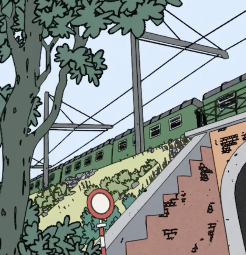
🖍️ A tutorial on how to render outlines as a post-processing effect in Unity. Makes use of an edge-detection technique based on depth, geometry and colors, and can be used in Unity's Universal Render Pipeline (URP). Can be used for game mechanics or stylistic rendering.
And is it supposed to have a sampler?
I figured I could just return the texture itself then sample it inside shader graph (the first function), but I got a 'can't convert from Texture2D<float4> to UnityTexture2D' error
You seem to be mixing up several things. There is pure hlsl API for sampling textures, then there's unity API thay builds on top of it for sampling textures as well, implemented as macros. If you're gonna use the unity API, you've got to make sure you're using it correctly. And vice versa, if it's pure hlsl, you also have to follow it's rules. Mixing the two wouldn't work most of the time.
yeah since there's no intellisense in HLSL it's hard to tell what's inherent to unity and what's regular HLSL
There is documentation though.
You can consider that macros are almost 100% related to unity API.
so I presume the 'TEXTURE2D()' stuff is unity macros, that aren't working because I'm inputting a custom value name that Unity doesn't recognise?
Yes.
gotcha
I'm trying to assign it from a custom render pass using buffer.SetGlobalTexture(globalTextureName, handle.id);
If you look at the examples from the link, they declare a sampler separately to the texture and never try to access it as a member of the texture. Unless I'm missing something.
TEXTURE2D(_CameraDepthTexture);
SAMPLER(sampler_CameraDepthTexture);
So, I'm not sure where to got that texture.samplerState. API from
SAMPLE_TEXTURE2D(_CameraDepthTexture, sampler_CameraDepthTexture, uvSamples[i]).r;
inside the outline shader code included in that tutorial
oh yeah the samplerstate stuff is from a different set of code and it didn't work, that's why it was initially commented out
But here you declare the sampler as a TEXTURE2D, not as a sampler
oh shit
neat I changed that and it compiles correctly now, thanks
now time to see if it actually works
oh shit I think it works
except for some reason the alpha is always one
and I also think it's rendering everything with the same material values, even though I'm changing the material colour between each render call
foreach (Renderer r in renderers)
{
    // Set material colour to contain the desired data, based on properties of current renderer
    material.color = SetDataToRenderIntoBuffer(r, camera);
    // Draw data to buffer
    buffer.DrawRenderer(r, material);
}
What's buffer?
Not quite clear what's going on in that code.
a CommandBuffer
Assuming you modify the same material every time. All of the objects rendered with this material would have the last color value you set to it.
ooh hang on considering I'm generating a material from scratch using code, maybe I could use an object pool to have as many unique materials as are necessary for what's being rendered?
or at least for the number of unique colours
Yes, you would need several materials or use material property blocks
I don't think I'll be able to use property blocks since that means altering the renderer object itself, since this is all for a screen space overlay effect
so I don't want the original object visuals to change when the effect is disabled
alrighty I'll get to using the object pool
i don't know why unity rotate direction of the texture but it is so annoying, how can i fix this ?
the texture showed in the scene view and the source texture have different rotations

Hi, does anyone know that if Unity (>2022.0) forces multi_compile to have an underscore option to use or not in compute shader?
Since I want to delete the underscore, but my compute shader complains an error only in runtime "Can't find kernel (0) variant with keywords: ".
(it's empty after the colon so I suppose the variant for no option is still generated? And I don't know why the non-option variant could cause any problem)
The "rotation" doesn't matter in your case as long as you are using equal-length plane. Just rotate your plane to fit your preferred direction.
What is inconsistent here is that the UV data in Plane mesh doesn't match your preference of the axis you want to align to.
why does unlit not get affected by fog?
Fog is more or less categorized as part of lighting calculations
Probably no more compelling reason than that for it
that makes sense i guess. I just wanted the effect of unlit, not affected by shadows, while being occluded by fog. is that possible?
Lit with texture/color in emission probably does all that
It has a separate toggle for Receive Shadows but emission is applied on top of shadows anyway
okay, thank you!
guys what if a shadergraph shader is as bright in the night as it is in the day?
how to fix
Thanks Cyan, indeed it seems that URP doesn't support extra passes (other than using the lightmode trick while breaking the SRP batching - also only one extra pass would be allowed in that case). I found an alternative using the RenderObject renderer feature while setting the override mode to shader: in that case all material properties are kept (so I can access shared data) and SRP batching is still working for the main material. Not 100% satisfied but it works and only requires to setup the main material once.
Is it an unlit ?
no
idk
its shadergraph
Shadows work on it
but lack of light doesnt make it dark
In the shadergraph settings you can select the target shader type.
I guess that if it recieves shadows, it is a "lit" type.
Did you plug things into the emission output maybe ?
Hey guys
Just a silly question
How expensive is one dot product in shader if I am targeting lower end mobile phones too? Also for more info, I am using the lit shadergraph
Yeah theres a texture in the emission
I saw someone advising to avoid dot products for lower end Android phones
dot product is a very simple operation (3 mul and 2 add for a 3D vector ), so consider it not expensive at all.
Well, this is emitting light, in the dark.
Ohh, that's a relief 🙂
Thanks
I created a simple shader to blend between moss and rock textures and on testing on an older device, it looks like the framerate drops quite a bit when the shader is covering a decent portion of the screen
If it can help you optimize a bit, shadergraph now has an Heatmap Color Mode to help identify computational heavy nodes.
It isn't very messy or large
Can you check if I am doing something which isn't optimal
Ohh
That's interesting
Lemme check
Yep, can have a look
Appreciate you!
May I directly share the shadergraph file in dm maybe
Here is fine if it's not secret. Or a (readable) screenshot of the graph it it's not that big.
Yes, no secret 🫠
Hold on
Also I am using the red channel of the diffuse texture to get a cheap hacky heightblend kinda look
Hum, I don't see anything particularly costly.
You could replace the Clamp nodes with Saturate and optimise the dot product (as one input is a float), but I don't think that would help the perfs.
You could also try implementing this to go from 4 to two textures samples.
Replace power by multiply ?

ohh
seems like power and clamp are a bit costly
if i understand the heatmap feature right
thanks! I'll look into all of em
Does anyone know where I can find/buy a pixel scaler shader?
Reddit
Explore this post and more from the godot community
I'll pay someone $100 to make me one from scratch too, if not
hqx shader on shader toy. take it free, but if u want to give me money, i will take it 
Oh, thank you! I've never heard it called that before
Do you know how you might make the same effect but like... In a render pass for Unity? :D_ _
Because I'm totally willing to pay for the convenience of that
During the fragment shader, do I have access to the respective worldPositions of each pixel?
I have generated a normal map using a shader graph. Is it possible to save it in a png?
Nvm got it thnx
Not by default afaik.
could you calculate that somehow, idk if its common to do position based calcs on frag shader
hello, how would i make it so that particles take priority over my cloud shader, aka how can i make particles get obscured by the clouds
right now when the particles are inside the cloud they render through it
I think there's a node for that in shader graph, so it should definitely be possible to calculate it. As for how, I'm not entirely sure. You'd probably need to pass the vertex world position as an interpolated value in the vertex shader output.
Either render them before the clouds, or make sure they are making a depth check and the clouds write to the depth buffer.
interpolation as in the position of the pixel relative to its triangle vertices? OK, thank you
Yes, in the vertex shader output you can specify what members the GPU would interpolate for you with an attribute or semantic keyword. Don't remember the details.