#archived-shaders
1 messages · Page 82 of 1
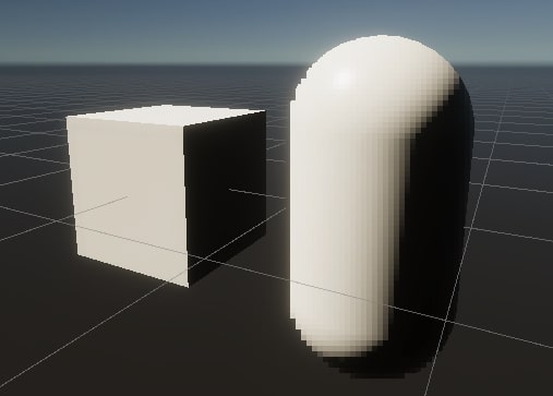
define "this"
if you mean that there's bright and dark part, thats because mobile diffuse is a 'lit' shader, means that it calculates light
So I was learning Unity Shader Graph and was trying to create a stylized grass shader. I got the result but i am unable to see any shadows of the assets in the scene. Any help with it? How can i cast the shadows on top of the grass. I am using terrain and scattered the grass on it. Plus I am using Unity URP.


Does anyone know what kind of shader shader graph makes?
what do you mean by what kinda of shader
its output depends on what render pipeline its used with, but it outputs a HLSL shader
you can easily view the generated code from it if wanted, its a bit of a mess to read though
ok thanks, i dont know too much but I know there's like compute shaders and vertex shaders. Is HLSL in that same category of shader types? Im using URP.
compute shaders are there own thing, but rendering you got vert and fragment shaders that are jsut different functions defined in hlsl
Why i cant modify values?

Does anyone know how to do depth textures for surface shaders HLSL?
I can't seem to find ANYTHING on it online
The game Turbo Overkill has this shader where a surface shows a different place. In this case, the breakable holographic material shows that nice nature background. In Unreal Engine 1 ( yes 1, from the 90ies) they did that for skyboxes.
I wonder how this is done in Unity. It's not just a render texture and not some sampled cubemap. Both spaces exist in 1:1 scale.

Also, this part of the fragmented glass half transparent over the BG looks like it's that shader showing that other place and putting the broken glass over it, so not a second render pass that only renders certain pixels als "the other place".

Could just be a second camera moving in a different area that is rendered first, assuming it actually is an environment and not just a skybox.
Then just have areas that don't clear before rendering on the second camera
It is an environment. The question is how is that done. It's not normal camera stacking which is basically another render on top of existing pixels and it's not normal from close to far rendering.
Is it possible to read an existing pixel and write it back while updating the depth buffer?
Could you elaborate a bit more what you are trying to do ?
Hello, I saw this topic on Unity forums (https://forum.unity.com/threads/setting-an-array-of-textures-possible.1021246/) which states that is possible to declare a texture array as a sampler2D variable[numOfItems] inside a HLSL shader.
My question is, is possible to pass from _TextureArray ("Texture Array", 2DArray) = "" { } property to this field inside the CGPROGRAMof a HLSL shader?
Unity Forum
I have an advanced shader in GLSL that takes an array of sampler2DArray. So, the GLSL has:
uniform sampler2DArray textureArrays[64]; //Note, 64...
Probably not. As bgolus mentions if the compiler even allows it it's probably unrolling to multiple single texture properties.
If you're using the 2DArray property type, you use Texture2DArray type in the hlsl portion - or macros appropiate for the render pipeline (for built-in RP there's an example on this docs page : https://docs.unity3d.com/Manual/class-Texture2DArray.html)

Yes I'm using those macros, the point is that I'm using UNITY_SAMPLE_TEX2DARRAY then how can I get the sampler2D from this? I'd like to adapt this code: https://github.com/jensnt/TerrainHeightBlend-Shader/blob/main/textureNoTile.cginc to use a Texture2DArray.
Neither I can't use this as an argument for a function: float3 getAlbedo(Input IN, Texture2DArray side, Texture2DArray top, int arrayIndex, float2x2 rotationMatrix) because: Unexpected identifier "Texture2DArray". Expected one of: in inout out uniform sampler sampler1D sampler2D sampler3D samplerCUBE sampler_state SamplerState SamplerComparisonState bool int or a user-defined type.
So I'm not sure how to continue developing my shader

GitHub
Unity Terrain Shader with Height Blending and more features - jensnt/TerrainHeightBlend-Shader
How can I use two clip calls in a single URP shadergraph?
i used to have a clip(x) and later in code a clip(y) in a fragment shader, but now moving to URP im not sure how to use alpha and alpha clip to make it work
See example here for using the macros with function params - https://forum.unity.com/threads/2darray-texture2darray-in-shaders.838828/#post-5543086, though I think there's a missing ) after the UNITY_ARGS_TEX2DARRAY(_MyTexArray macro
I'm trying to make edge detection for water effects
For an opaque shader where the alpha isn't needed, you can use two Step nodes each with a different threshold and Multiply together. Then keep the Alpha Clip Threshold port at 0.5
Otherwise can probably call clip() from a Custom Function node
AAAAh that was it, of course, step
I was trying to add, or multiply them but was getting weird values
That's so much more clean
Hi, not sure the best place to ask this as it covers particles, compute shaders and rendering. Essentially I'd like to do the following set of things:
- Have some simple particles running on the GPU (Spawned from CPU).
- Have these particles collide with the environment - somewhat accurately, and including backfaces, so depth buffer collisions are out. I'm currently thinking voxel or SDF representation of the world.
- When these particles collide with the world I want to generate (append) some data that a subsequent compute shader will process to generate some simple geometry.
- After that, I want to render this generated geometry into a rendertexture.
So, it's complicated and I don't know if any parts of this can be done inside existing tech - like VFX graphs (though I don't think they will let me do the collision data generation). Apart from the CPU particle spawning, I know all of the rest can live on the GPU. I'm guessing I'm going to have to write all of this from scratch aren't I? Anybody done anything like this?
Yes, also you need to use UNITY_PASS_TEX2DARRAY()
Then for example, I could pass my texture array into the textureNoTile code (https://github.com/jensnt/TerrainHeightBlend-Shader/blob/main/textureNoTile.cginc). But I have questions, for example, we have:
fixed4 textureNoTile( sampler2D samp, in NoTileUVs ntuvs )
{
    // Use modified UVs to sample a texture
    return lerp( lerp( tex2D( samp, ntuvs.uva, ntuvs.ddxa, ntuvs.ddya ),
                       tex2D( samp, ntuvs.uvb, ntuvs.ddxb, ntuvs.ddyb ), ntuvs.b.x ),
                 lerp( tex2D( samp, ntuvs.uvc, ntuvs.ddxc, ntuvs.ddyc ),
                       tex2D( samp, ntuvs.uvd, ntuvs.ddxd, ntuvs.ddyd ), ntuvs.b.x ), ntuvs.b.y );
}
Where is declare this tex2D constructor? Because in HLSLSupport.gcinc I only see float4 tex2D(sampler2D_f x, float2 v) { return x.t.Sample(x.s, v); } and which is the equivalent for UNITY_SAMPLE_TEX2DARRAY(), because uva, ddxa, ddya, ... they are fixed2 types
Because as we said, we cannot recover the sampler2D from a UNITY_SAMPLE_TEX2DARRAY() call, no?
I'm looking in docs: https://learn.microsoft.com/en-us/windows/win32/direct3dhlsl/dx-graphics-hlsl-tex2d-s-t-ddx-ddy ddxa ddya stands for Rate of change of the surface geometry in the x/y direction
But I don't think we have such thing on UNITY_SAMPLE_TEX2DARRAY
I found this: https://forum.unity.com/threads/texture2d-array-mipmap-troubles.416799/#post-2730309
#if defined(SHADER_API_D3D11) || defined(SHADER_API_XBOXONE) || defined(SHADER_API_GLES3) || defined(SHADER_API_GLCORE)
    #define UNITY_SAMPLE_TEX2DARRAY_GRAD(tex, coord, dx, dy) tex.SampleGrad(sampler##tex, coord, dx, dy)
#else
    #if defined(UNITY_COMPILER_HLSL2GLSL) || defined(SHADER_TARGET_SURFACE_ANALYSIS)
        #define UNITY_SAMPLE_TEX2DARRAY_GRAD(tex, coord, dx, dy) tex2DArray(tex, coord, dx, dy)
    #endif
#endif
But the following prompts: undeclared identifier 'UNITY_SAMPLE_TEX2DARRAY_GRAD' how can I check the SHADER_API_xxx directive I'm using?
Unity Forum
Hey. I've used atlases for my own terrain texturing in my project. And I've had troubles when mip map was enabled. After that Unity 5.4 came with...
You need to set the camera DepthTextureMode to Depth, and then in the shader the texture should be available as the _CameraDepthTexture variable : https://docs.unity3d.com/Manual/SL-CameraDepthTexture.html

Alright
How can I convert that to a float I can use? I'd also like to covert it to alpha
Well, it is a texture, so you need to sample it to get the float value. It's a single channel texture, so either .r or .a value is the raw depth.
Look into UnityCG.cginc for helper functions to convert the depth to other spaces (like eye space : aka distance in meters)
Once you have the float value, up to you to do anything you'd want and plug it into the alpha output
Thank you
Hi! I have a pretty complicated sub graph that i would like to use in a compute shader, is it possible?
actually nvm! I forgot that yhe important code is already in an hlsl
Hey all! I am currently trying to find a way to efficiently create a outline/stroke effect on my Render Texture, currently I have a white/black image and am trying to add/expand extra mass similarly to the blue area is done in this image (blue area is an example to show area made in photoshop, actual result would ideally be white as-well). Does anyone know of a shader effect I could use to expand the white area as such, any help would be amazing, thanks!

I would suggest the flood fill algorithm again
is that not for "filling" empty space? Or is that also possible in this instance?
I did end up getting my old system working, just looking to make it even faster than it is currently by reducing the amount of blur passes needed!
Not necessarily
It can be used to expand a region of pixels with diminishing intensity
Like how Terraria, Minecraft and Starbound do it, as I tried to explain some months ago
Alright, I'll have another look into it! I mostly stopped looking into it prior since I had found a working way to implement the "blur" method, which gives the exact result I was aiming for for only a 10%~ fps cost in editor. However, if I were to find a cheap way to give an outline/stroke effect I could probably bring that down 80% since the blur passes would be able to fill a lot more area with less passes, but I'll look more into flood fill since I'll likely need to use it in other areas of my project down the line either way, appreciate it!
The my knowledge there are many different methods and algorithms to make a flood fill outline, the best of which depends by platform and use case
I would guess they are cheaper than blurs, on average
Probably pretty similar if I had to guess, based off a first look at some of these references it looks fairly similar to how these blur passes work.
I was really just wondering if there would be a really standout obvious solution to creating a stroke/outline cheaply that I had been missing, but I'll definitely give this a try if that isn't the case.
The flood fill definitely seems like it has a lot more potential as far as additional parameters + I could probably reuse a lot of the flood fill outputs for a variety of different systems in my project, definitely a good one to keep in mind!
There is any one obvious solution, but several contenders
https://alexanderameye.github.io/notes/rendering-outlines/ check "jump flood algorithm"
As well as the link in there
Amazing, thanks! I'll try that out.
Yeah just off a quick glance, the extrusion method shown in the link you sent looks like exactly what I was looking for!
It probably isn't
You're working with pixels, that one is for geometry
That is also true, I was reading the title for the wrong method.
The first one I was referring to, but it seems there isn't a title for it "fresnel effect" potentially?
Fresnel effect is also for geometry
Only blur and specifically jump flood are relevant to your case
Ah I see, I'll look more into it! Thanks.
Okay, it isn't giving me the result I want
float _depth = Linear01Depth(tex2D(_CameraDepthTexture, IN.pos).a);
And in the vert function
o.pos = UnityObjectToClipPos(v.vertex);
UNITY_TRANSFER_DEPTH(o.depth);```
The result I want is LIKE this, this was made in shadergraph

Try .r (or .x) on the depth texture instead of .a

what are the uv naming conventions i need to follow so that i can use multiple uvs per mesh, is it simply uv(0), uv1, uv2 etc etc?
and now i have two normal maps. one on uv0 and one on uv1, if i simply add them together, will they only affect their respective uv or will it turn into a mess?
Your normal maps can't be "on" an UV channel, but you can intend them to be sampled with coordinates on a specific UV channel
And then blend after sampling
I don't think any names for UV maps will be kept when exporting the mesh
the blend after sampling part, thats what im interested in, how do i do that
bc this does (obviously) now work

and for non normal im guessing i use the standart blend? and it will keep the previously set uv mapping?
I don't fully understand what you mean
UV map is not "set"
It could be thought of an address where to sample a texture pixel from at the moment when you sample a texture
After that you only have the color of the pixel you got by sampling to work with
yes, but when i "set" the uv map on a texture sampler its set or isnt it? i have a mesh with 2 different uvs and 2 different textures for the corresponding uvs, since i do only have a single channel per property to plug it into im trying to combine 2 texture samplers that have different uvs, just like in the pic above but with albedo textures instead of normal maps
Yes, you specify an UV channel to sample with, after that you only have the resulting color that you can blend or do whatever with
ok, so there is no way to have a different texture on the green flats considering im constricted to a single material

You should need only one UV map for that, that has the flat bits on one portion of it, and the stem on another
If you want them to be on two different ones for some reason, you'll additionally need some way to separate or mask the different parts
Otherwise you're sampling two overlapping UV maps on every fragment
maybe im fundamentally misunderstanding uvs then, but if i add the flats, it would mean i need to make space for them in the uvs which would also mean that the stem would not loop the texture that nicely since it will also loop the flat bits aswell to fix that i would need a substancially higher res texture than 128 by 128
You will need extra geometry for repeating sections of the UV maps, or perhaps not if you can allow it repeat in only one direction (which is how "trim sheets" work)
I would increase poly count and texture resolution to accomodate the leaves
To have extra UVs and and a mask map or vertex colors to mask between them has its own cost that's probably higher anyway
hmmm, ill do that then
Please I need help with a math formula. I need a shader that accepts parameters _Rotation and _Segment and gives me the shape seen on the image (ignore the test image lol). The shader calculates the angle of a point from the pivot and saves it as variable angle. I can't figure out what the right thing is.


I was a bit to lazy to do it in code, but is this what you'd want ?

well... yeah... but i found a better solution than what i requested, so im fine. thx tho
Hey! So I've been looking into jump flood a lot more and it seems extremely efficient especially at higher pass counts than gaussian blur so it's basically a perfect match for what I am looking for, however I am still quite unsure if it would work with diminishing light values, since it is being used as a "passthrough" through walls as we discussed prior a few months ago, adding an outline directly would likely not account for varying light opacities as shown below, would you know of a way/work around to allow that to work, and also account for color in the flood fill? (Example below)

The only way I can currently theorize as potentially working is individually passing each light to a separate render texture and separately masking/jump flood filling each of them in their respective colors and blurring them together afterward, but that still has the opacity problem as to my knowledge the stroke would effectively force all the area in the light to be fully opaque in whatever color the flood fill "outline" is set to be?

this is the current documentation I am referencing, which I've found to be great at explaining how jump flood works and directly comparing them to other methods (such as gaussian blur).
I guess you would have to sample a texture that differentiates empty space and filled space
Usually you would fill around a light, accounting for walls, rather than fill around a redundantly filled area (this also prevents your light from passing through walls)
I don't know how colored lights work with this method, maybe they're calculated separately and composited
I think colored lights would need to pass position and color separately to directly using the already compiled "light texture" I have been using, but yeah, diminishing light amounts with flood fill seems problematic.
I think we expect light to diminish over distance and to be impeded by walls
I do have the "outline" mask which I can use to separate the "filled" and unfilled space.
yeah, the idea is light diminishes a lot faster through walls but still overlaps to reveal a bit of it.
A really high blur pass does this amazingly but is super computationally heavy.
(based on this depending on the amount of passes around 10x less efficient than flood fill)
Blurs are not generally used for this
Yeah, I see why. But it seems to be almost required to get a starbound-esk light system that isn't insanely complicated. (even a low blur pass combined with other techniques for blurring the result if jump flood fill was used).
I think you're overcomplicating it, and overcomplicating it even more in an effort to avoid the jump flood algorithm
I am definitely open and trying to use the jump flood algo but as we discussed before wouldn't that not work with diminishing light amounts?
I don't understand what you mean by that
All your reference games get by with it fine
Ben Golus' example is for outlines, so it's not 100% the same case
That is true, I might-as-well test it with shaders since I really don't know if my suspicions are true at all. My only real evidence of the light amounts not affecting it is using a "stroke" in photoshop, which creates an effect like this:


I don't understand how photoshop is relevant here
just for testing similar algorithms for creating outline effects, I am unsure of what is being used here. But it produces an outline so it was worth trying I thought.
I'll give the flood fill a try and see how it goes, the only real way to know is to try I suppose.
Is it possible to change the bayer matrix used with alpha to coverage?
I defined a macro like: #define UNITY_SAMPLE_TEX2DARRAY_GRAD(tex, coord, dx, dy) tex.SampleGrad(sampler##tex, coord, dx, dy) to be used on this code:
fixed3 textureArrayNoTileNormal( UNITY_ARGS_TEX2DARRAY(texArray), in NoTileUVs ntuvs, in half normalScale )
{
    // Use modified UVs to sample a normal map, also inverting red and green channels where needed due to mirroring
    return lerp( lerp( fixed3( ntuvs.ofa.z, ntuvs.ofa.w, 1 ) * UnpackNormalWithScale( UNITY_SAMPLE_TEX2DARRAY_GRAD( UNITY_PASS_TEX2DARRAY(texArray), ntuvs.uva, ntuvs.ddxa, ntuvs.ddya ), normalScale ),
                       fixed3( ntuvs.ofb.z, ntuvs.ofb.w, 1 ) * UnpackNormalWithScale( UNITY_SAMPLE_TEX2DARRAY_GRAD( UNITY_PASS_TEX2DARRAY(texArray), ntuvs.uvb, ntuvs.ddxb, ntuvs.ddyb ), normalScale ), ntuvs.b.x ),
                 lerp( fixed3( ntuvs.ofc.z, ntuvs.ofc.w, 1 ) * UnpackNormalWithScale( UNITY_SAMPLE_TEX2DARRAY_GRAD( UNITY_PASS_TEX2DARRAY(texArray), ntuvs.uvc, ntuvs.ddxc, ntuvs.ddyc ), normalScale ),
                       fixed3( ntuvs.ofd.z, ntuvs.ofd.w, 1 ) * UnpackNormalWithScale( UNITY_SAMPLE_TEX2DARRAY_GRAD( UNITY_PASS_TEX2DARRAY(texArray), ntuvs.uvd, ntuvs.ddxd, ntuvs.ddyd ), normalScale ), ntuvs.b.x ), ntuvs.b.y );
}
The following error prompts: Unexpected token '('. Expected one of: ',' ')' at Assets/Resources/Shaders/Terrain/textureNoTile.cginc(93)
I have two questions, can I see the character position where the errors occurs? I understand that is caused because tex.SampleGrad isn't allowed, but why? Do I need to share some project settings?
i cant find where the error is, but im only getting the normal on one of the sides


Is the output node in Tangent space too? (And can you use the existing Triplanar node?)
what do you mean with output node? i dont have any triplanar nodes. but am calculating the uv's from world space


I think Tangent space still requires the UVs to be good on the mesh (the UVs are part of the mesh, they aren't just made by the shader); can you try outputting UV as base color and see what it looks like? (All faces should have gradients on them, like the unity default cube)
the mesh has no uvs at all
what do the tangent and bitangent vectors look like?
they form the red and green components of the normal afaik
where can i find those?
Usually if you're doing triplanar mapping you avoid using tangent space as those are aligned to the regular UVs.
The Triplanar node gets around this by doing a World->Tangent transform at the end, but that's kinda an unnecessary calculation as you can change the Normal Output Space under Graph Settings to World instead)
See the code snippet on that node page, and/or this article - I think Unity's node uses the "whiteout" blend iirc
does what i'm doing count as triplanar?
Yes it's the same
If you don't need different textures on each axis you can just use a couple Triplanar nodes to handle all this for you
#archived-shaders message i looked into other options because someone mentioned you could get a similair effect without using it. but i couldn't find a different option
i only want a different texture for the topside and try to blend it into the sides. was also thinking of using a vertex shader again so i could change the textures at certain locations
but ill have to call it a day for now, thanks for the links and ill be busy working on this again tomorrow
is the texture type set as normal map? because it doesnt look like 'normal' normal map
is there any reason why my shader looks different in scene view (Image 1) than in game view (Image 2)? it seems like the alpha clipping is just not working in scene view and i dont know why? when i make the surface type transparent, the clipping works but it was give it that weird affect where you can see the trunk (Image 3)


This is the shader graph as well

I been trying to follow this tutorial
https://youtu.be/eYzihHPtGJE?si=quUZOWNPT-pV9k9x&t=726
But i have noticed that when ever i try to animate the uv offset the Voronoi noise it breaks apart.


On this tutorial let's see how this Stylized Vertical Beam attack is done in Unity! We are gonna use Shader Graph and VFX Graph to build this bad boy and by the end you will have a great start to improve on.
00:00 Intro
01:07 Starting the VFX
02:10 Cylinder Mesh in Blender
03:02 Vertical Beam Core
04:58 Beam Background
05:56 Fresnel Cylinder
0...
Am i missing how you can animate this noise, i also tried on amplify shader as well and it had the same effect

Does anyone know how to apply different mixtures of this texture to a material, so like, 100% lighting, that bright part is nothing, 50~75% is the small dots, 25~50% is mixed of small dots and heavy dots, and 0~25% is heavy dotting

wait- I just figured it out
yeah, its the same texture and normal thats projected on the other side face
i've taken this screenshot from the game timberborn and i want to achieve something similair. where i can give a different texture to the top of the mesh and for the sides. with ideally some controll with how those edges blend with eachother. and being able to render different textures that also blend depending on fe if water is in range

for now im guessing i could achieve this with vertex coloring. but i would have to add a vertex in the middle on top of the mesh to hold the information and keep the texture centered on the voxel. or could that be solved another way?
I think you can combine world space xz texture mapping and uv mapping.
worldspace for the top surface so they dont have any seam, then mask it using texture with uv mapping
You'll need an auto tile algorithm though
For what it's worth, I made this in my nodes library : https://github.com/RemyUnity/sg-node-library/tree/master

Now, that's purely based on the normals, it won't blend the edges of the top faces.
Like it was mentioned, if you want this sort of edge blending, the distance to the edge information is needed, probably in the form of some additional vertices and UV / Color
i'm trying to understand but i don't really follow. are you saying have the grass on the mesh uv's and the dry rock projected over it and then mask the mesh uvs with it?
the nodes look usefull. is there an explanation on how to get them into my project somewhere?
hey when im editing my material settings for example of my water shader is there a way to preview the animation if im editing the waves?
Sorry, I didn't write any doc on that repo 😅
You can simply import it using the package manager with the "import a git package" button
I just hope it still works with recent versions ...
what is the exact link i should use for this? i also tried https://github.com/RemyUnity/sg-node-library
https://github.com/RemyUnity/sg-node-library.git
Exact 🙂
For next time you want to grab a github repo :

ty got it now
i've added some uvs to my mesh aswell, is 0 to 1 per face good enough or do i need to tile those uv's how i want them for that shader?
🤷♂️ That depends on the way to plan to use them
Hello, its a project in HDRP, in unity 2022.3.10f1 and my colors are in green here in my shader butin the scene my color 2 is ok, it can change but color 1 does not work and stays black and dosn't change when i do


don't you have a script somewhere that set this color to black?
otherway you can try recreate and rename a color property to see if that solve your case
yes, thats what i will try yes
mayeb its just a bug
can anyon help me
why?
bayer is a recognized good algo
Don't ask to ask
im currently trying to make a shader (graph) where no matter in which rotation the prefab is placed in the scene, it will face the same direction based on a vector3 like in the pic. never worked with any sort of orientation/rotation in shaders so i dont really know where to start

Is there a reason you can't just rotate the renderer correctly?
the objects will be instanced on a terrain so doing it with a shader seems easier
I guess you could pass the shader a transform matrix and use that to transform the vertices
I've used this when trying to use local-space in a shader that's used on an overlay canvas
local space gets lost (it's just the canvas's local space)
i made a windshader, but i am kind of confused, it works with noise. what i want is that the wind isnt so uniform and moves everything in waves, but to have it more random. how can i do that?

guys, super massive noob just starting with unity, do shaders made with the shader graph works with all render pipelines or are they render pipeline specific?
Render pipeline specific
thank you very much
Hi I have switched over from Unity's default lit to the https://docs.unity3d.com/Packages/com.unity.toonshader@0.8/manual/index.html Unity toon shader and its laggy as hell now, is there something Im doing wrong or do I have to buy a third party one?

(for reference this same screenshot would easily yield 200+ fps in editor with the lit shader since theres really nothing graphically intensive going on at all)
Did you ever solve this? I am encountering this now
Assuming the blocks are all the same size in a grid, you could do the blending in world space
In my experience unity toon shader isn't prohibitively expensive to render, so something else could be wrong
According to your screenshot your framerate is bottlenecked by your CPU, not by your GPU
Odd I have a proper 13700k, I don't struggle to run anything really
And again, only happened with the new shader but thanks for the insight I'll do some more investigation
You've got a lot of batches btw. Could it be that the shader broke a batching of some sort?
Both cpu and gpu rendering performance can bug out in the editor for various vague editor reasons
Restarting and library deletion may help, but ultimately you want to measure performance in a build
I've only used the toon shader package on URP where batches aren't a problem
Though it does support BiRP
I think that's a key part of it, but I have no idea whats different other than the shader. I'll try it in a build and find out
What do you mean by library deletion sorry?
The shader alone can break the GPU instancing for example and if the shader doesn't support GPU instancing, you are not gonna get any GPU instancing happening. Do you remember whether you had the batch count somewhere around 6k prior to the change?
Library is a folder in your project's filesystem that contains all temporary editor-generated data
If this problem appears to have no logical cause (though here it seems like it might have), consider deleting Library and letting the editor rebuild it
But restarting is usually the first remedy in that case
I believe it was defo lower than that, like 1k with multiple k saved by batching lol
Okay will try this thanks
Is there any indication that unitys toon shader doesn't do batching properly?
I believe its outlines have to be rendered in a different pass
And since they're mesh outlines they also increase the polycount by rendering the mesh an extra time
Ah
That sounds like the probably reason then, theres many meshes technically even if each one is low poly sigh
I thought the outline might be the reason, I don't think there's much way for me to have my scene the way it is without rendering every mesh twice
Even though theres like 4 materials rip okay I'm thinking thanks
I guess other games get around it by having essentially a single mesh and material for whole buildings and objects rather than many little ones like I have
Use the frame debugger to see why the draw calls are not batched.
Ty will try
With inverted hull mesh outlines including the outline and its color in the mesh and texture itself is a very efficient option for performance, but perhaps not for workflow
Additionally there are many different varieties of outlines
https://alexanderameye.github.io/notes/rendering-outlines/
Many of them rely on post processing instead
Excellent, thanks I'll take a good read of it all
Probably can roll my own outline or something if it's all that I need
Got a shader graph for ice from an older version of unity cause i was following a guide, but then tried to import it as a package into a newer verison of unity and it won't work even after i've tried the Converter

Any ideas on what to do?
The project im working in, is the 3D URP Core base, preset, whatever it's called
It looks like you may need to upgrade the material to URP
doesn't the converter do a swathing upgrade to everything in the project?
and i just created this Material raw on the spot and tried to apply the shader
so it SHOULD already be convertred since i just created itin the newer verison, right?
could i copy everything IN the shader's node graph, create a new empty node graph, and just paste all the settings in there?
I'll try that as soon as i remember how to create a new node graph lmao
Ok, got it working. I could manally change the vector's settings to use URP instead of Built In
Auto converter doesn't work on it, so had to manually do it
how do I get loops to work in shader graph?
I was worng, the material looks like it should in the preview, but when i apply it...and that piece on the mesh literally shifts around as i move the camera, the shader on it does

it sounds interesting but cant find anything about worldspace blending
What I mean is that you know the size of the grid, so rather than using vertex data to tell where to blend, you can use the modulo of the world position since that will be the same for every block
It works for blending the edges of a "top square", but it would do it for all the sides, ignoring adgacent tiles that have the same texture/height.
This information needs to be passed to the shader in some way, and other than using vertex data like UVs / Color, I don't really see how it could be done. (Or have some sort of terrain heightmap sampled to check neighbours ...)
I'm almost tearing my hair out trying to figure why my shader isn't working
So, I created a script to index a texture according to its colours into 16 separate colours
using this formula Color(i / 16f, i / 16f, i / 16f, alpha) where i is the index of the colour
this gives me a grayscale texture
but when i multiply the values back again by 16 in the shader graph, I don't get the correct values
I have compression set to none and filter mode set to point
so Idk what I'm doing wrong
so if I store the values as 0, 1/16, 2/16, 3/16, ... in the grayscale texture and multiply them back by 16 in the fragment shader, it doesn't work
they should give me 0, 1, 2, 3, 4, ... but that doesn't seem to be the case
I've tried rounding, flooring and ceiling the values but it still doesn't work
If someone is willing to help, I can send the shader graph file as well as the textures
I'm using urp as the render pipeline
Might be a colorspace issue. Try also using the Colorspace Conversion node
Or try unticking sRGB in texture import settings
Oi! I'm pretty new to shaders and have been trying to fix a small isue i'm having. Where the render feature is overriding a shader i have for portals. I've added in two images one is with the feature on and the other off. Anyone got any ideas on how to solve this?
Render feature:
https://paste.ofcode.org/396Cj478z6HVdMZHX9fY2iE // The shader
https://paste.ofcode.org/ppkTGYaAXQWRTqLQZUME6t // The feature
https://paste.ofcode.org/QXiDihNtYgVJY2Zj3UYEph // The pass
https://paste.ofcode.org/ermYKRHFGFQktTzsCc9yxH // Controller for the feature
Portal shader:
https://paste.ofcode.org/njtzEihcUA8TVfEvLFdFZz // Portal shader
https://paste.ofcode.org/unNb2ySypsKvusQDTbNjQx // Portal code


OH MY GOD thank you so much it worked
I have spent frickin hours trying to figure out whats wrong

wanted to post this here aswell, apparantly the shader issues i had dont seem to be caused by the shader, it works fine on the test cube but not on my mesh

Issue with normals I guess from the look of it ?
Maybe the mesh has bad normals ? If it's imported, you could try enabling "recalculate normals" in the import settings.
#💻┃unity-talk message #💻┃unity-talk message i posted about it here, its a procedural mesh i use mesh.RecalculateNormals() on, but i also had an issue with uv mapping so im suspecting some underlying issue i haven't pinpointed yet
Maybe also tangents
i dont call mesh.recalctangents yet, i could give it a try
Did you also add this ? https://docs.unity3d.com/ScriptReference/Mesh.RecalculateTangents.html
Normal mapping requires proper mesh tangents for tangent space normals, or you use object space normals
mesh.Recalculate tangents did fix my normal issue. the mirrored uvs seem to persist though

only problem with recalculate tangents is that it massively slows down my mesh generation, i'm currently rerendering the entire chunk for every minor change
Well, if you use the position .XY, .XZ or .YZ coord to project the texture, you need to invert one axis when looking at the other side, it makes sense.
If would be more optimized if you are able to provide the tangent and normals yourself instead of relying on the recalculate methods
i think i could manage that for the normals, but i dont even have a clue what tangents are😅
To put it short, the tangent if a normalized vector, perpendicular to the normal, and pointing "toward" the UV.X axis on the mesh
(well, more or less perpendicular to the normal, but you get the point I hope)
i think so, ill look some more into it. thanks for the suggestions and the help🙂
In the case of your mesh, the tangents could all be easilly guessed from the normal.
If the normal is 1,0,0, the tangent is 0,0,1 for example
(or 0,0,-1 ... I always mess up the right or left hand rule)
Well, if you use the position .XY, .XZ
hey guys i wanna create a game where the visuals are similiar to fall guys. notice how the mesh shines and looks kinda like a wet chewy bubblegum?? or more like a shiny colorful assets ? well how to create it?? i want my assets to look just like how fall guys assets are made.
Play with the smoothness value off the standard or /Lit shaders
thanks remy
I need a bit of help. I'm trying to get a fog of war like effect for my games map, but my current shader graph doesn't seem to be doing the trick and I don't know what else to add to it.
My biggest problem right now is that the fog just looks REALLY watered down. Like I want the fog to be thick.
I was thinking maybe adding tiles beneath these ones with the same shader but the fog has a different scale/offset,
I just tried it out and it gives a decent result. I might need to do 3 layers, but I was wondering if there's anything else I can do with my shadergraph to enhance the result.
ALSO, what could I do to make the fog move across all the tiles? Because currently you can focus on a dark spot in the noise on one tile and watch it just disappear as it gets to the end of the tile because the noise is basically a copy paste between all the tiles, same exact offsets
I'm using the shader graph in an HDRP project. Unity isn't letting me change a property named _EmissionColor. If I change the name to _EmissionColor2, it works fine.
This seems a bit weird!
Heya, can someone help explain what's going on with the rendering order in my scene?
I have 5 "layers", just RawImages with a shader graph material attached. Queue Control on all of them is set to "Auto". I have a fish as another RawImage in the middle of all of them, and I'm expecting it to show up tinted green/blueish from the transparent images in front, however it doesn't render at all. I tried attaching a non-default material to the fish, in case that was the problem, but the result persisted.
I'm using URP if that changes anything.


Canvas or non-Canvas? What "Material" in Graph Settings?
Only UI components can go on a Canvas, and their shaders must support UI rendering
Canvas components are depth-sorted by their hierarchy order
Canvas, both Unlit.
Only Canvas in Shader Graph should be used then, which Unity 2023 adds support for
I'd try removing all Materials from the image components, to reset to using default shaders
Then at least the sorting should work as expected
I'm on 2021.3.16f, no option to update.
Not sure what you mean by "Only Canvas in Shader Graph"
I'm relying on the Shader Graph to do specific stuff, can't just throw it out.
no visible difference between the two


Very confusing that this field is named "material" but it defines the features available to the graph

Oh, that option in the dropdown does not exist in 2021.3.16f1
Indeed
Does that mean making shader graphs for UI is unsupported?
Officially
There might be some hacky ways to enable SGs for Canvases pre-2023
But if those don't work out, you'll have to abandon either SGs or Canvas in this case
.....how deligtful
But first of all verify that the shader is the problem by emptying the Material field of the image components
Huh yeah without the shader hiearchy changes the visibility
Something to try is to split the foreground and background into separate Canvases, with the fish in between on its own Canvas
Even if your custom shaders will break sorting within a Canvas, there's a change it'll still work between them
how would i make the firework effect here in URP shadergraph? it's not clicking for my brain
So is my best option recreating the images as meshes instead?
oh wait sorry took a sec to process the message
hold on lemme try
Welp, it does work

A Canvas is a mesh, once generated from its components
So kinda yea
Which is also why it requires special shaders within
It's so weird though, I was using Sprites earlier and they rendered as expected when set to Opaque, but had the same issue when switched to Transparent
Still best to research a bit if there's some other missing features or potential pitfalls to using the unsupported shader, and if there's something to remedy it
Sprites have also their own sorting logic, but it breaks with an opaque shader falling back to ordinary depth buffer sorting
https://docs.unity3d.com/Manual/2DSorting.html
And worth noting again that sprites or other non-UI objects should not go on a Canvas
Ultimately it depends on what you intend to make
If URP doesn't support something, there's less resources about customizing it
But out of the box it has many tools that can speed up development like shader graph, vfx graph, 2d lighting and most importantly SRP Batching
Currently it has more features than BiRP, but is still missing support for a few very specific ones
The color is going through a gradient or doing a hue rotation uniformly on the whole firework effect
The firework explosion is likely a flipbook / texture sheet animation
Those explosions may be sampled multiple times in different positions and composited / blended over previous explosions, with a time offset for the animation
yeah figured the rest. was only confused by the firework shape. was split between a spritesheet and polar coord manipulation
I need some help with a 2D shader. I wrote a very simple shader in accordance with a YT tutorial and it seems fine except for this weird translucent white box around the sprite

I tried to put it over a BG to illustrate the weird box. I can post the shader's code if needed
Either the texture's background is not fully transparent, the shader is blending a color over the transparency, or reflections (if any) aren't excluded from transparent areas
Hmmm well the background of the spritesheet seems to be fully transparent. Is it possible putting it into Unity caused something like that?
When I give it the normal sprite default material it doesn't have this issue
Should I share the code to see if it's the second suggestion?
You could but I'd prefer to first know which render pipeline it's for, and if it's Shader Graph or not
URP and I tried to code this shader
I often use shader graph but I don't think it can do what I'm looking to use the shader for. But if it could that'd be amazing
Which is what?
Which is that I'd like to be able to build or find some kind of a template so I can easily make shaders that apply any blending mode I might need based on the calculations for them that I've learned
I'm not sure if shader graph can give a material itself a blend mode as opposed to using blend modes in nodes
Pastebin
Pastebin.com is the number one paste tool since 2002. Pastebin is a website where you can store text online for a set period of time.
Either way, this is the code
I guess those are what you would have to work with
Curious what other blending modes you require
Well, I already have access to materials for additive and multiplicative blending
But I'm exploring what kinds of effects I can make so I felt like the best way to do it would be to do this so I theoretically have any of them at my disposal that I might need
It's a bullet hell game. I'm trying to create an effect for warning the player of a certain area that's about to be attacked. I tried using multiply but that doesn't work on dark backgrounds. Additive would run into a similar issue on light backgrounds. So maybe something like overlay would yield good results but really just being able to easily experiment would be massive
Overlay would be neat
I don't see what the issue could be in the shader since it looks like you're just directly using the texture color and alpha
Ok I'll try using the material on some other sprites and see what happens
Same sort of deal seems to be happening
Something isn't quite right with the alpha
If I put it on a blue fireball

Oh wait hang on I might have it
Changed Blend One OneMinusSrcAlpha to Blend SrcAlpha OneMinusSrcAlpha
It does indeed appear to work on any sprite

I get the feeling that's not everything and that the problem isn't truly solved by that but I'll just keep going and hopefully nothing new comes up
Thank you for your help
I ran a build just a few hours ago. I'm running another build now, and it looks like all of my Shader Graph shaders are being recompiled -- I'm seeing zero cache hits in the editor logs.
I did switch from development mode to non development mode, but this still feels wrong..
It does look like I got hits on the next build (for macOS, after this most recent Windows build...)
i've been thinking about how i could get some blending between my top and side faces for my procedural mesh, and i was wondering if it would be possible to do height based blending for every individual XZ's height? im currently storing that in an 3d array but dont know how to access those values from a shader

The video explains my problem and shows my current ShaderGraph, but incase you don't want to watch it.
My problem is that is there is no accompanying fog tile, my fog doesn't fade out as it gets closer to the edges, so you can see a sharp edge. I'd like to know if there's any way I can fix that.
Example: There are 4 fog tiles, bottom left, upper left, bottom right, upper right. The player explores the bottom left fog tile so it fades out and disappears. The player can easily see the edges of the rest of the fog tiles because the fog doesn't fade out as it gets closer to the edge where the explored fog tile was
Is the result I'm looking for even possible with a shadergraph?
Hey so in my game I have a primarily rainy/wet environment, and I want my gun models and FPS arms to have raindrops on them and appear wet, does anyone know how i'd do this? (I am just assuming it would be a shader.)
(Something like the image is what I am going for)

i can't give you a clear answer because im trying to make a fog of war myself right now but i saw a simmilar problem on a video but it's quite a long one i'll link it to you just in case it might help : https://youtu.be/Y7r5n5TsX_E?si=YJcFRA-KA-qGIz_y

Sign up via my link will get two FREE months of Skillshare Premium https://skl.sh/romanpapush
—————
#Update: Blender 2.8 is out! https://www.blender.org/
—————
Heyo my dudes!
I really hope you will enjoy this advanced tutorial for complete beginners!
By the end of this video you will master the Air-Bending techniques of the ancients and will le...
i also saw a lot of people using Gaussian blur
but not sure
sorry for not giving you a clear answer
Anything helps at this point XD
I tried finding an answer myself, but I haven't found anything. I don't LIKE using ChatGPT, but I got desperate and ChatGPT SEEMED to know what it was doing, but it didn't help at all, as expected XD
ChatGPT SEEMED to know what it was doing, but it didn't help at all, as expected XD
Well, that's what chatGPT good at, it's good on making itself look smart XD
as for your problem, I can only think of some options
- using autotile fog (not shader stuff actually), but you'll need to make fog 'tiles' for it
- Or, render the fog to a rendertexture, then blur it, if you want to keep your scrolling fog unblurred, you need to blur only the fog tile and use it as masking for the scrolling fog
🤔 actually, you might not need to blur at all, just render the fog 'mask' at low resolution, and upscale it, as long as you dont use point filtering for the render texture, it should 'blur' it on upscale
did any one tried to upragade a shader from built in to urp by hand ?
F it. I think instead of a fog style fog of war, I'm just going to make stylized cloud sprites and have like 10 or 15 in a single tile, and when the player explores a tile a script runs that makes the clouds slowly move out of the tile and fade out.
I'm better at scripting than using shadergraphs lol
I"m in the same Unity version across two projects. My shaders work in one, but i try to click and drag them over to the other proejct window, and they turn purple.
I don't know why it's doing this
Different render pipelines perhaps
does anyone know how to make an easy wetness shader? I want to make rocks in my scene appear wet
if you respond please ping me ty 🙂
Hey guys, I made this custom node called from_to_rotation imitating the unity built in function (using a method that works from git). It does exactly as I would expect, I have a lerp to interpolate between two normals and it rotates as expected
however, you can see how it's jarring

How could I add an offset/how could I calculate how much to move the ground position so that the circle doesn't look so suddent
instead of looking like A, it should look like B

Alright found the way, i just had to displace it by an amount of the vector
Hi, could someone explain to me what "eye" sampling in the scene depth shadergraph node means?
viewspace units from camera plane
@regal stag Thanks, how does it differ from raw?
Raw is the value straight from the depth texture (0-1 and stored non-linearly for better precision - and may be stored in reverse depending on platform)
I've got an article with a lot of info about depth stuff https://www.cyanilux.com/tutorials/depth/
Thank you very much
What package should i include to use Linear01Depth() function in shader?
For what render pipeline?
What is the proper way to mix two smoothness maps together? Lerp just gives me a transition between the two. I think Adding is what I want, yeah?
Maybe add, maximum or lerp to override one with the other? Probably depends on the situation
To be more descriptive, I have a base smoothness map for my rock, and a detail smoothness for when you're up close. I want to mix these, but without losing the information from the base smoothness.
Urp
I think it should be auto included along with the main Core.hlsl one then. But for SRPs the function has an extra param, so use Linear01Depth(rawDepth, _ZBufferParams)
Okay, I'll check
Thanks
How do shore lines work broadly for water shaders?
Initially I thought they worked a bit like intersection effects based on depth but then the camera angle would affect the thickness of the shore line, and that doesn't seem to be how things work physically?
The common method involving subtracting eye depth values does change thickness at different camera angles
@regal stag Okay, thanks again. I guess there is no method addressing this specific issue other than manually constructing a representation of the shore in a texture or something of the likes?
I have seen the depth texture been rendered from top down view prior to the actual water shader to get the actual depth but that will obviously have it's impact on performance
@dim yoke Thanks, any pointers towards the direction they took to achieve it? It's a small game, I may be able to get away with a large hit from water
That is true. The pixel shader does not have any information of its surroundings besides the depth and color buffers/textures which in this case is only enough to give some estimate but not calculate the actual value
btw what type of shore line effect are you looking for? sometimes scaling the eye depth based on the surface normal at the bottom can give better estimate for the depth but that mostly works for shallow and even bottom ponds
Okay, thank you again
So, I could create a map of the shore by uh, I guess raycasting all in directions at sea level and finding the closest distance to shore, then baking that into a texture and sampling that texture to determine distance to shore in the shader?
Hm, stylized simple lines slowing slowly washing up the shore
problem is camera is orbital
You could do that but that would definitely be really expensive. You could use different camera that renders to a render texture and only draws the depth. It depends on the render pipeline how that would be easiest impelemted
Oh, so then by having that camera at a fixed angle, shore lines thickness would be consistent
Is that hte idea?
yeah, from the top down angle preferably. I think sebastian lague did that in one of their coding adventures, let me look up if I can find it.
holy this guy has done work
It was actually something else that they used but I don't see why the idea wouldn't work. If you could prebake the depth texture in your modelling software (or in unity), it would be even better for performance thought in theory you would only need to render the depth texture once at the start of the game
Ah yeah now I get you. So basically every pixel on the texture points to a depth, which is the compared against sea level.
exactly. Like any real life depth map of a body of water
@dim yoke Well, here I go! Thanks for your help
How do I display the texture on the left of the text on a custom shader ?

what is this blue-ish shader?

and how can i remove it?
nevermind, it was due to the skybox
I understand this may be a very dumb question, but I am confused as to why this wouldn't be clipping the sprite, based on the "_UVOffset" variable which is being set through code, I have tried subtracting vector from the "Y" of the UV, and nothing seems to alter the sprite itself, I understand I am very likely being dumb but I cannot for the life of me seem to get it working, any help would be amazing! Thanks.

the intended outcome is having the sprite shown below, update it's visible "height" based on the "fill" parameter I have set via code, I am currently setting it as follows:
liquidInstance.GetComponent<SpriteRenderer>().material.SetVector("_UVOffset", new Vector2(0f, 1f - (liquidHeight / 16f)));
^ my tile is 16x16, and "liquidHeight" is an int of how many pixels tall the tile should be, so / 16f is a normalized value which can be used as a Vector for UV, (in theory).

Offsetting will cause the texture to be sampled outside the 0-1 range, but that doesn't mean it'll clip pixels or make them transparent. It'll either tile/repeat the texture or clamp to the same pixel colour at the 0/1 edge - depends on the texture's wrap mode. Though for a full blue texture the outcome is the same.
For a height/fill, it's likely you'd want to Step using the UV node and the height value and use that as the alpha output
Oh, okay thank you I'll try that!
Also for future reference, putting a property into the UV port on a Sample Texture 2D doesn't offset it, but overrides every pixel to use that coordinate. You'd use a Tiling And Offset node to apply an offset
Oh, okay. I initially was splitting the texture's UV into X and Y and adding the Y Offset to the Y, but that didn't work so I was sort of just trying anything haha.
Yea that way works too, though bit more wires to deal with
I am not to familiar with the "Step" node, from what I am seeing though based on this descriptor: https://docs.unity3d.com/Packages/com.unity.shadergraph@6.9/manual/Step-Node.html
How would this work with a Vector 2 such as a UV? I don't suppose I could just plug the UV and offset into the Edge and In inputs?
From what I've tried the output is clear which I assume means the Step is outputting 0, is there possibly something I am missing?

I'd probably split and only use Y axis
This is plugged directly into the "Alpha" output of the "Sprite Lit" shader graph.
Oh okay!
Hmm, still no dice unfortunately. The closest output was a small sliver was shown when the "fill" of the tile was 1, but it would disappear at any value lower. For simplicity I have converted the Vector 2 to a float, and I am either constantly getting a "filled" tile or a completely blank invisible one, should my float be normalized to for example 0.5f/1f if I wanted half of the sprite visible?


this is the output of the image above flipped
It depends if the sprite is a single texture or part of an atlas (as then the mesh uvs are only a portion of the larger 0-1 range)
It won't change the output as it's truncating down anyway, but I'd split the UV to only the G/Y axis as well
The liquid tiles are using a white 16x16 pixel sprite, which is then using a liquid material which changes it's color and ideally visible fill amount.
Okay sure!
Then yeah, a value of 0.5 should be half filled
Still no dice, but just for future reference the shader graph separates each pixel in the UV separately, so having a step node would be "pixel based" and not alpha for the entire UV? Because if the step node is always outputting 0, or 1 I'd assume if that weren't the case I would either get a "filled" tile or an empty one?

this results in the filled tiles being a single pixel tall and any other "fill" amounts being empty
I also tried adding another UV node, and combining the unchanged X to the output of the Step node, to hopefully create a new UV using the X and Y but that didn't work, I am unsure if it is even possible to plug a UV into an alpha output.
Maybe try it without the property and just hard code 0.5? I'm not sure why it wouldn't be working
Okay, so hardcoding it works so something on my script's end is broken appreciate the help!
Ah, I figured it out. I have two liquid creation scripts so it was only working for the falling liquid creation!
Do you mean a shader that distorts water when a player moves through it, or a static distortion effect?
If you want to learn about shaders I'd look into getting to know HLSL syntax and starting there, if you want to have player movement affect it I'd recommend looking into emitters and how to utilize them while making shaders.
Anyone on here familiar with custom pass volumes? Specifically I have a bunch of objects on an interactable layer that I have a selection shader for, and I only want it to render on that one specific object when the mouse hovers over it. I just cant figure out how to mask out all the other objects to only render the shader on that specific one when the cursor is over it.
When I get home I'll link a good video which may help push you in the right direction.
When i dont know how to explain exactly, i have a 2d gameobject that i use as water and i want that anything that is inside that gameobject (the player inside as example) get distorded with a shader
I'm sure there are quite a few guides on YouTube explain in depth how to do just that I would recommend looking into, there are a variety of ways to go about doing that to achieve different effects with different varying levels of difficulty. Just Google "Unity water distortion shader", and I'm sure you'll find something that can walk you through it better than I could.
A short introduction to custom passes in Unity's High Definition Render Pipeline.
u can basically copy this approach
use a “selected” layer
So I have the selected layer I want, the problem I'm running into is its rendering over all those objects in the layer. Essentially its a selection effect, and I just want it to render over the one object when the cursor is over it and I want to mask out all the others that are on that same layer, but I still want them to render. So I'm wondering if there is a way to do that without having to turn on and off the custom pass.
Trying to write a compute shader for frustum culling. Arkano on the unity forums described a pretty simple method but I'm having trouble implementing it. Does anyone know of any examples online (github repos, etc) of this method for frustum culling? All I can find is examples of GPU frustum culling that uses parallel prefix sum which is a pretty complicated algorithm that I just can't wrap my head around.

So I have everything on the layer I want it to render on, my problem is I only want it to render on the exact object I have set to that layer when my cursor is over it. And that's the problem I'm having. I have no way to reference the specific game object if it's a part of that layer and set the custom pass to only render on that specific object in the scene.


Anyone have a good tutorial for water shaders?
if i have an object with many child objects of different materials how can i greyscale the whole heirarchy from the parent down with some shader that replaces the child materials but the issue is if i need to no longer be greyscale i need to re-apply the previous materials it currently seems very tedious to go throug them all swap the material and store what the previous material was, or give all of them a custom mader shader which has its own problems too
Correct me if I'm wrong but to me it seems what arkano is suggesting is to use InterlockedAdd in order to calculate the prefix sum sequentially. The problem with that is that GPUs are designed to to do extremely parallel work and therefore a question arises: why not do the work in CPU if you are doing it sequentially anyway? Unfortunately in order to do frustum culling, you must calculate the prefix sum and parallel algorithm is the only way to make it extremely fast whether you like it or not. To me the Hillis Steele scan doesn't look easy per say but not too bad either. Maybe the best resource I could find on it was this slideshow https://people.cs.pitt.edu/~bmills/docs/teaching/cs1645/lecture_scan.pdf. Is there some specific part of the Hillis Steele implementation that you are specifically unsure about?
hey, chatGPT created a shader and material that basically change all of the tilemap colors to gray, but the lightning doesn't work after that, how can I fix it?
code to shader: https://gdl.space/ixamigidig.cs


I assigned a normal map in the vertex shader, but when I access the "normal" property in the fragment shader, I still get the default normal of the mesh. Is that expected behaviour ?
Not sure what is wrong, should I also assign the tangent ?

What do you mean by "the normal property"?
The block called "normal vector"
Or more specifically, getting the view direction in tangent space
Oh you meant assigning the normal map in vertex shader, I see now. I'm pretty sure it should change accordingly. Does setting the normal have any effect otherwise? What type of normal map is that?
Aaaah I edited fragment to vertex but I changed the wrong one >.<"
I think I got the issue, the vertex shader is only evaluated for each vertex insead of each pixel, so the details of the normal map don't carry over
That is true actually, didn't realize that. Only the value at the vertex positions is interpolated to the fragments so it will get very blurry since it's only one normal value for each vertex blurred out over the triangle
Then, when I get a vector in tangent space, how do have that tengent space be affected by the normal map ?
what is the alternative for shaderGraph node "IsFrontFace" in hlsl unity shader (URP)?
It's the SV_IsFrontFace semantic used in the fraggment input struct (or frag function param)
Is it set by unity automatically, if i see both sides?
It's set automatically yes (probably not Unity but by the graphics API)
okay, thanks!
Found an example in case it helps - https://github.com/przemyslawzaworski/Unity3D-CG-programming/blob/master/face.shader
oh thank you very much! it helped:)
If you just wanna apply normal map to your object, you should do that in the fragment shader if that's what you are asking
Trying to debug a compute shader using unity's renderdoc thingy. How can I see the contents of a compute buffer from within renderdoc?

I can see the dispatch calls but I can't seem to figure out how to see the data of the compute buffers

How would I get translation/position from a TRS matrix in a compute shader that is made like this on the CPU:
TRS = Matrix4x4.TRS(
    vertex,
    Quaternion.identity,
    Vector3.one
)
The last column should be the position so I think float3 pos = theMatrix._m03_m13_m23 should do the trick (note the swizzle)
thanks!
Having a weird issue with my culling. Is there anything that I could be doing wrong from just this gif?

there's a lot of code (nearly 1000) to deal with this so it's not very easy to post my code atm
hum guys i have a shader that seem to work in editor but when i enter play mode it stops working, how can i paste it here so you can check it?
how can i paste something like in this grey square?
https://forum.unity.com/threads/frustum-culling-with-compute-shader-how.1552049/ my code (and the code that zbajnek on this post ended up with) is based heavily on acerola's culling code from his grass rendering videos.

Unity Forum
I'm working on a little project for a while - creating an area where you can spawn a bunch of grass. I've overcame a major headache when figuring out...
arkano states that it may be caused by the fact there's no check to make sure id.x is within the range of valid date
but I'm not entirely sure how I would do that.
@hexed sorrel how can i paste something ina kind of grey square? like for code
https://gist.github.com/BradFitz66/0066d105e9b4e003f8c9b6049d393433 Attempted to do bounds checking for id.x but it didn't seem to work. Here's all the relevant code that I feel like I can share (this is modifications to a paid asset so I'm only really comfortable posting code that is mostly my own and not part of the paid asset)

includes:
- Entire ComputeShader
- When the ComputeShader is ran, just before DrawMeshInstancedIndirect is called
- Code for setting up the ComputeShader's buffers and their data.
!code

Posting code
📃 Large Code Blocks
Use links to services like:
https://gdl.space/, https://paste.ofcode.org/, https://hatebin.com/, https://paste.myst.rs/, https://hastebin.com/
📃 Inline Code
Surround code with three backquotes. Not quotation marks.
To format as C#, add cs to the first line:
```cs
// Your code here
```
Add a comment with a line number if there is an error message.
Stil having issues. I've gone and replaced the compute shader and it's initialization with the exact code Acerola used in their project, but I'm still getting these artifacts.

Another thing I've noticed is that it doesn't work with an orthographic camera at all. I assume I have to do something different here?
//Calculate VP of camera before sending it to compute shader to determine if a point is within view
Matrix4x4 P = Camera.main.projectionMatrix;
Matrix4x4 V = Camera.main.transform.worldToLocalMatrix;

Matrix4x4 VP = P * V;
or here?
    //Vote on whether or not a grass blade is within view of camera.
    float4 position = float4(_GrassDataBuffer[id.x].TRS._m03_m13_m23, 1.0f);

    float4 viewspace = mul(MATRIX_VP, position);

    float3 clipspace = viewspace.xyz;
    clipspace /= -viewspace.w;

    clipspace.x = clipspace.x / 2.0f + 0.5f;
    clipspace.y = clipspace.y / 2.0f + 0.5f;
    clipspace.z = -viewspace.w;

    bool inView = clipspace.x < -0.2f || clipspace.x > 1.2f || clipspace.z <= -0.1f ? 0 : 1;
    bool withinDistance = distance(_CameraPosition, position.xyz) < _Distance;
I'd appreciate any help since I'm way out of my depth here.
I don't think I understand

Why does my shader still show like it's the basic one in the preview?

because the preview of the scene color is grey
Oh, that makes a lot of sense now that I think about it
Also, dunno if I can ask this but
where can I find some 3D noise?
clipspace maybe faulty here
I'm kinda new on this shader thing, how do I use this? I downloaded it and now it's in my project folder
If it's in the correct folder, the nodes will appear under "subgraphs" when you make a new node
The problem I have is that I need the noise as a 3D texture, not as pure 3D noise
How can I convert 3D noise into a 3D texture?
How so?
My only issue with that theory is that its the exact same as Acerola's code and they didnt have this issue in their video
But they also had a chunking system that was culling chunks on the CPU so maybe that hid the issue?
The bigger problem for me is that orthographic cameras dont work and my game uses orthographic cameras
thanks
Posting code
📃 Large Code Blocks
Use links to services like:
https://gdl.space/, https://paste.ofcode.org/, https://hatebin.com/, https://paste.myst.rs/, https://hastebin.com/
📃 Inline Code
Surround code with three backquotes. Not quotation marks.
To format as C#, add cs to the first line:
```cs
// Your code here
```
Add a comment with a line number if there is an error message.
oopsie
Does anyone know?
Do I need to do anything different for the camera MVP if I'm using an orthographic camera?
Have I not given enough info?

Where are you expecting to assign a value to it?
Turns out Unity staight up wouldn't open the graph inspector
I had to restart the editor
crossposting [this question](#archived-urp message) here for better visibility. hope that's not deemed spam... I'm not sure which channel is more suitable for such URP-meets-shaders questions 😛
hi, anyone know how what I'm doing wrong with this shader? It appears to be custom-made for one specific type of object (right), how do I apply it to other objects?

Could someone please share a screenshot of a Shader Graph using the URP Triplaner node
like this ?

Perfect, thank you
It seems to start to do the effect on th left sphere.
Maybe you just need to tweak some parameters ?
the shader effect works but it has this packaged in 3d model
Is the one on the right the one that works?
maybe you just have to change the texture?
I have 3 cloud sprites, and I want to apply a shader to them. Currently I just want a noise that moves across the image, and then maybe distort the clouds in a way to make them seem like they're "floating" in a way. But what I'm finding right now is applying a noise effect to the entire image, even the pixels that are supposed to be transparent. How could I get around this?
It seems I'm horrible at finding solutions on the internet because the way I'm wording my problem is not resulting in anything related to it XD
You could use the alpha of the clouds to affect the noise(s) intensity
Like this?
I feel like this is horribly wrong, mainly because it seems like it's trying to render what looks like Batmans logo in the last multiply XDD
Also... is my Texture2D sample supposed to look like it was copied and pasted several times with an offset?

Why do you need it to be a texture, in this case?
That 'batman logo" is just the effect of having the clouds texture alpha previewed in 3D mode, yand can change it on the multiply node if you want to.
And the "copy paste" effect is expected, shadergraph doesn't display the alpha value in previews, so you are looking at the RGB values from the texture, without alpha mask
This surprisingly works, but I want the noise to overlay ontop of the image, and not completely replace it. :/
From what I see in the graph, it is already doing this.
Maybe just the cloud image doesn't have enough contrast to distinguish it from the noise ?
You can change the noise intensity by lerping it to white
hey guys, does anybody know why my alpha clipping thing isn't working?


I'm not very good at shadergraph but I think it's set up right in the preview 🫠
Try unconnecting from Alpha Clip Threshold and set that at 0.5

Is alpha clip also enabled on the material ?
Hello !
I noticed all my meshes have indices like [0, 1, 2, 3, ...] because each triangle needs its own 3 vertices and I add them in the correct order.
Is there any way to get rid of this useless buffer and to only keep the vertices buffer ? (I guess it could be faster ? )
I use the advanced mesh API with SetVertexBufferData, SetVertexBufferParams, ...
hey! I think it's enabled? I set in the universal tab in the graph inspector

is there another material tab somewhere I should be looking at?
How are you drawing the quads? though vfx graph? Maybe it's a setting there too
yeah I
it's a VFX graph thing
let me see
I think it is supposed to read from the shader

if I remove the shader graph from the output the alpha clipping and all the other options come back
(in vfx graph)
the trails seem to look better in scene view

but still not getting that alpha clip I'm looking for
I fixed the alpha issue (not the alpha clipping) - but man it doesn't look very nice...
UnityEngine.Mesh cannot be created without indices. You can draw non-indexed vertices directly with Graphics.RenderPrimitives.
Oh ok, I'll look at that, thank you ! 🙂
Hi all! Is it possible in unity urp to write a fragment shader which doesn't return a float but a specific datatype like a uint16. I know, it may not make any kind of sense. But is it technically possible when I write a simple shader pass or do I need to define a custom rendering pipeline from the ground I?
I mean I would write a fragment shader which returns uint and put it into a custom rendering buffer. Then could Unity visualize it?
i didn't see a material help channel so i guess this belongs here. i have this transparent material trying to make it look like dark glass or like a crystal, but i can't see the back of the object through the front i just see right through it

Why uint16?
how come i only have 5 types of shaders to add but none of the graphs the guy has in the tutorial i'm following?


Is there any way to turn black textures into alpha? Like, I want to convert the level of "whiteness" of a texture into level of alpha
A shader can use a texture's color channels as the alpha channel to do more or less that
Or you can use the texture importer's "alpha source: from greyscale" to generate it
Or use the additive blend mode which instead of alpha uses the brightness of the texture for blending
https://media.discordapp.net/attachments/517108768933281843/1259556123678085130/image.png?ex=668d6e0d&is=668c1c8d&hm=10c04da5e796b7f00bfa0f62e7806f54ba2716bad63321ea687f1e13bdd54d7f& does anyone know what is wrong with CoreRP/HDRP shaders here? Did I do something to it?
Things I did:
Rebuild library folder
Reinstall HDRP and Core RP
Update Unity
Modify shader code, comment problematic line


I don't think that limit is device specific. I think that's a hard limit in DirectX.
I see, okay
Also, is there any way to divide two long values so that it ceils instead of flooring the value?
Ah using the systen.math.ceiling and working with doubles
Do you know if there's any method that returns that value directly instead of hardcoding it?
That's what I tried but got 32
no worries, Im just gonna stay to 256 and use that as a boundary
I think I nailed the alpha clipping problem - the shader graph has clipping enabled, but for some reason the vfx graph asset it generates does not

does anybody know how I can edit that vfx asset?
Yo can someone help me out with fixing my shader. I've copied one from a unity 2017 tutorial and made the changes suggested by the unity manuals to make it work for unity 6 (or at least work for the URP) however apparently the surface shader can't be used for vertex displacement. Does anyone know how to fix it? Before changing it all to use the URP syntax it shows the mesh displacement working when in wire frame shaded, however it's stuck on the missing texture pink. But if I change it it stays on default white and doesn't do anything.
If it's easier please feel free to dm and I can share the code I have there
Question about shaders and theyr performance impact, I've set up a shader that is something like an abstract screensaver, its animated and seamless.
I've made up 7 different version of them by just chaning up the value of the variables.
Currently when I need to change from one to another I use the same material and change the values stored in the script.
In terms of performances is it lighter in this way or by just creating 7 different materials for every combination that gets swapped it via when the event is raised?
Here's an example, since when changing from one to other I fade everything to black, I can potentially swap the material
hey guys bit of a noob here - just comparing preview to play mode and i see there are white dots on the model... is this due to the mesh / texture not being properly alinged ?

Hello i create an underwater game but i want to have fade of black here but i can't find how i can do that if anybody have idea , thank a lot 😉

The problem isn't vertex displacement - surface shaders do not work in URP at all. You must use vert/frag style shaders, or graphs
Can apply a fade in the shader based on the worldspace Y position. In shadergraph it's something like Position node (World) -> Inverse Lerp (in T, with A/B set to where the fade should start and end) -> Saturate -> Multiply with textures/etc for Base Color output.
I would like to use another datatype, namely bfloat. My hardware not supports it, however I believe it is possible to emulate somehow.
But for what purpose?
The context may be important
It could be color leaking from mip mapping, but since it only happens in Game view at that distance it's probably caused by MSAA
UV islands that are too close will bleed over in many situations
Gotcha - these models are exported from BlockBench so Im' guessing the texturing / uv is the issue
Yup looks like the UV's are jammed up too close - moved some stuff quickly to see and you can see the difference, much thanks!

hey, i created a custom renderer-feature and a render-pass (see link) in the render pass execute method im bliting the cameraColor texture onto a texture, that is defined in the pass by using a material. then this texture that is being modified by the material (and its shader) is blited back to the cameraColorTarget-thing. (Is this correct?) And how to reference this texture handle that i created in the render-pass in shadergraph to modify it? https://pastebin.com/yAQKnnrP
Pastebin
Pastebin.com is the number one paste tool since 2002. Pastebin is a website where you can store text online for a set period of time.
Do you know any ways to easily convert the shader to work then? For the most part it seems to work, it's just when I change it to HLSL to fix the missing texture it stops doing the displacement
I'm trying to use this shader but it stretches really badly when on an object that is not flat, is there a way flatted the objcet uv based on the camera view so the shader will loke more like the one on plane? This object and its camera will never move in the scene so that will not be an issue...


What you're describing sounds like screen position, but localized within the bounds of the object. I've seen solutions for this in the past, but I'm struggling to find it now. I don't think there's any common term for this, because it's not a very common requirement.
But basically, you take the Screen Position, offset it by the screen position of the object's center and then scale it by the screen-size of the object. That last bit is the difficult bit, figuring out how big the object is in screen space.
If you know the object is always going to be a sphere, you can calculate it manually in the shader. Otherwise, you probably need to use the object's bounds and calculate the screen positions of the corners or edges to get the screen bounds.
So where should I use the screen position node? Keep in mide that the effect doesnt depend on the object scale/size

I've tried thtis butt it unfortunately denatures the rest of the shader 😐
Simple acceleration purposes, like the way half substitutes float.
"Acceleration"?
Just to be sure, is this the right spot to insert the screen pos node?

is it where the old UV node was
Hmmm yeah, but maybe you want to override the UV0 on the Tiling And Offset nodes too with that
May also still want to use these groups too

Mhh maybe adding it also to tiling and offset solved the problem
it a bit tricky since the effect is a bit abstract its hard to figure out if is the result is the one I was looking for 😅
So what about this question?
Let me simplify it: Source-wise, is it ok to run 2 shaders in one and switching from one to another by a lerp or is it better to have 2 separate shaders anche swapping it via code?
Swapping materials is cheaper
Otherwise you're running every effect for every fragment at the same time
Ok, what if the 2 materials come from the same shader so same nodes but different paramater values?
Still the whole shader executes with all its calculations
so I guess its the same, like running 2 script with different var values
Unless there's some runtime shader variant thing to prevent it that I don't fully understand
Hey. I'm trying to transform a Shader Graph shader used for billboarding sprites towards the camera to HLSL code.
I've attached the shader graph in an image, and the HLSL code in a file.
I am getting a syntax error in my HLSL code because I'm not sure how to convert the Transformation Matrix to HLSL:

The transformation matrix for InverseView should be something like UNITY_MATRIX_I_V rather than a property.
Though you might be able to use a slightly different method. Graphs use the inverse view as the Position port is expected in object space, while vertex shaders can output directly to clip - might be cheaper
float3 vpos = mul((float3x3)unity_ObjectToWorld, v.vertex.xyz);
float4 worldCoord = float4(unity_ObjectToWorld._m03, unity_ObjectToWorld._m13, unity_ObjectToWorld._m23, 1);
float4 viewPos = mul(UNITY_MATRIX_V, worldCoord) + float4(vpos, 0);
o.pos = mul(UNITY_MATRIX_P, viewPos);
(From https://gist.github.com/kaiware007/8ebad2d28638ff83b6b74970a4f70c9a)
I am trying to make a transparent unlit shader in URP, but when I set the surface type to transparent and the alpha to 1 it is still completely transparent. It shows an opaque preview but when I put it on an object it is invisible, which makes no sense. Does anyone know why this might be happening?
Maybe check Frame Debugger window. Check if it's actually rendering. (If it's not, might have removed the layer from the Transparent Layer Mask on the Universal Renderer Asset?)
Thanks, I figured it out from that. Turns out my custom post process is messing up the transparents layer so its invisible. For my use case it would work to just change it so the transparents are rendered after the post processing, is it possible to do that?
my post processing is a full screen pass renderer feature
also just checked and transparent layer mask is set to everything so its this for sure
I'd probably try a custom feature to draw the fullscreen pass in the Before Rendering Transparents event, if the Fullscreen one doesn't have that in the dropdown already
I guess you could also remove all layers from the Transparent Layer Mask and use a RenderObjects in After Rendering Post Processing to render them all. But that's a bit messy imo
oh I fixed it, there is an option for before rendering transparents. Thanks
Ah good, wasn't sure if it was limited to later events
yeah, if it was anything complicated like that I think I would have been out of luck lol. The rendering and shading stuff is so complicated, I just started learning it recently
Question about shaders and theyr
hey guys what shader would you recommend for high performance on mobile? i used unity's built in mobile shader thinking it was the best in terms of performance but it doesn't receive realtime lighting and that's a dealbreaker for me. the perfect shader for me would be a simple diffuse shader which receives realtime lights. any recommendation is welcome.
im pretty newbie when it comes to shaders, how can I make it so the pixels in my censor shader will scale based on distance?

because when you are too close the detail is too high and when you are too far the detail is too low
This line took four hours to create...

I managed to code a shader that takes in two points and draws a pixel perfect line between them. Now the next step is... Making it actually useful. I think what I need to do is make this code somehow access the screen size, and somehow use that to render its pixels???
Anyone who wants to help, I have a unity package with the work I've done so far.
Right now, the line is drawn in the texture space of the object using the material, but ideally, it would render to something like a quad in the scene, and somehow take the main camera and use that as a reference to draw it "right"
bumping this in case I managed to pick the very moment when everyone was still waking up 😄
hey, i created a custom renderer-feature and a render-pass (see link) in the render pass execute method im bliting the cameraColor texture onto a texture, that is defined in the pass by using a material. then this texture that is being modified by the material (and its shader) is blited back to the cameraColorTarget-thing. (Is this correct?) And how to reference this texture handle that i created in the render-pass in shadergraph to modify it? https://pastebin.com/yAQKnnrP
Pastebin
Pastebin.com is the number one paste tool since 2002. Pastebin is a website where you can store text online for a set period of time.
Hello, I'm trying to enable GPU Instancing on a HDRP project without success, the shader graph and material inspectors are greyed out. How could I enable it?


Seems that you are looking at the "default material" of the shadergraph, which is not editable.
You need to either create a new material using that shader, or a material variant of this default one, to be able to edit it.
Thanks by creating a variant its now editable 👌
Now I need to figure out why I still have the same amount of draw calls with gpu instancing enabled😅
That's because of SRP batcher : https://docs.unity3d.com/Manual/SRPBatcher.html
The SRP batcher basically takes over previous unity batches optimisation (dynamic batching and auto GPU instancing).
Enabling GPU instancing on a material in HDRP is usefull if you are manually drawing instances using the Graphics API
Ok thanks, so I should have only one game object that draws all instances of the mesh?
If you really want to use GPU instancing with regular gameobjects, check the "Intentionally removing SRP Batcher compatibility for GameObjects" section of the page
I will take a look, thanks 🙏
Is that possible to render a color based on dest color without using the GrabPass?
So I have a map which has color1 and a background with color2. I want to do next: if geometry is on color1 than render color2 and vice versa.
If you don't want grabpass (or a similar custom texture), I think the only other way would be Blending commands.
https://docs.unity3d.com/Manual/SL-Blend.html
https://docs.unity3d.com/Manual/SL-BlendOp.html
Probably won't work with specific colours, but you could use black/white and apply an image effect to swap those out for actual colours later.
Haven't tried it but the BlendOp LogicalInvert sounds cool, assuming the target platform can support it. Otherwise Blend OneMinusDstColor OneMinusSrcColor might work, based on : https://forum.unity.com/threads/invert-colors-shader.205244/
I don't want to use GrabPass because of performance. The problem with inversion it will not actually change to the color I specified.
But the idea of using post processing after inversion 👍
Thanks
I'm trying to create a rather simple fog shader using the Full Screen Pass Renderer Feature and I'm trying to emulate how the default cubemap skybox shader does exposure, however at a value of 1 my sky is completely overblown.

Or I'm completly missing the point on how to blend the skybox with a simple exponential fog
Also there appears to be a rather big difference between the scene and game view when it comes to the density
There are different types of HDR textures that need to be decoded in different ways. How certain are you that you're performing the correct decoding for the HDR texture you have?
I am not. I dont understand what the decode instructions do ```// Decodes HDR textures
// handles dLDR, RGBM formats
inline half3 DecodeHDR (half4 data, half4 decodeInstructions)
{
// Take into account texture alpha if decodeInstructions.w is true(the alpha value affects the RGB channels)
half alpha = decodeInstructions.w * (data.a - 1.0) + 1.0;
// If Linear mode is not supported we can skip exponent part
#if defined(UNITY_COLORSPACE_GAMMA)
    return (decodeInstructions.x * alpha) * data.rgb;
#else
#   if defined(UNITY_USE_NATIVE_HDR)
        return decodeInstructions.x * data.rgb; // Multiplier for future HDRI relative to absolute conversion.
#   else
        return (decodeInstructions.x * pow(alpha, decodeInstructions.y)) * data.rgb;
#   endif
#endif
}``` this is the code that decodes it
in the skybox shader half4 _Tex_HDR; is simply declared and never filled with anything
If your texture format is already HDR, you don't need to decode it. You only need to decode it if it's encoded using dLDR og RGBM. dLDR means the values are saved at half their intensity to fit into a normal LDR texture, and the shader is supposed to multiply by 2 to get the real values. RGBM is similar, but instead of a hardcoded 2 as multiplier, the multiplier gets stored in the alpha channel as M for magnitude.
This sort of encoding is more common on mobile platforms, where HDR texture support can be missing or slower on some low end devices.
As it happens this is intended for a mobile platform. But I cant figure out if it is RGBM or dLDR or what ever

what does this do ColorMask[_LightLayersMaskBuffer4] 4 as it fails unity 6 hdrp when on older hdrp it worked
The same decode method should work for both, because Unity will adjust the decode instruction float4 depending on the encoding format.
So you think unity autofills in the _Tex_HDR variable ?
Cause it does not in shadergraph
It will be called [YourTexturePropertyName]_HDR and is automatically filled by Unity. It's part of the core material system, so how the shader was made or the render pipeline being used doesn't matter.
it does not let me just do a half4 _Cubemap_HDR; in the custom funtion it says it is not initialized.
Because you're using the String mode in Custom Function, which only lets you write the function body. You need to define it outside the function, so you have to do it in a file.
Or just define it as a hidden property in the Shader Graph, that should work too.
On Blender I see for a material there is a checkbox for "backface culling" which stops rendering the opposite side of faces.
I also see a checkbox for "Show backface", which does something I don't know how to describe so I have attached a screenshot where the left side has it enabled and right side has it disabled.
I know in unity I can enable/disable culling in a shader. Is there an equivalent option I can enable/disable in a shader that corresponds to what blender's "Show backface" checkbox seems to do, based on the screenshot?

Hello, I'm rather new to unity shaders but I'm curious about something. I wanted to implement a simple gaussian blur effect to an image and I understand the process is to convolve each kernel in an image with a given matrix in order to achieve the effect. I'm trying to understand how I would do this process efficiently
Looking to replicate this effect. Any tips?

Specifically the wispy line between the two planets.
Seems like a line renderer with a reduced width in the center.
Anyone have any ideas about this?
#archived-hdrp message
Looks like two funnnel shaped meshes with something like a line renderer between them, or another type of stretched mesh
Got a better image for these.

Those funnels look even more stretched so it could be one mesh being stretched between the points, with multiple layers
Stretching could be accomplished with a skinned mesh renderer or a vertex shader
Ya looking at this planet there definitely seems to be an inner/outer mesh.

Maybe even a third in there for that spike.
The geometry can be anything if it's a stretched mesh
Though with blend modes other than additive it can be tricky to prevent the polygons from being drawn in the wrong order

#unitytutorials #unity
The file is available here: https://github.com/sanliuk/DropRain-Unity-Shader-Wet-VFX
Free offer at on paypal if you want at: eraltdet@gmail.com
Or support by subscribing this channel
Method used:
Amplify shader with render texture
Scroll shader,
render texture shader
what I made with vfx graph can be replicated with ...
sorry wrong conversation it was for a particle system. anyway could be helpfull for shaders too!
Shader Graph 'compiles' down to HLSL right? So, there is no reason that i should assume ShaderGraph is inherently slower than typed HLSL
the problem with shadergraph is (unless you look it up in the manual) you dont know what is inside the node, does it have many expensive operations or not? Like voronoi noise node with for loops and if inside
If it's typed, you'll immediately notice those loops and might reconsider to just bake it into texture and do a simple texture lookup
https://hastebin.com/share/zudopixehi.cpp
Can someone help me? I'm having trouble with this shader I'm writing, specifically, I'm having trouble getting the top and bottom of an object, then converting those points into points in screenspace.
Hastebin is a free web-based pastebin service for storing and sharing text and code snippets with anyone. Get started now.
The idea with this shader is that, if you put it on a flat plane, it will draw a line from the top of the plane to the bottom, converted into Screenspace coordinates.
Ok, understood. Thank you
Hello all!
Can someone explain to me, how does the Texture Size Node currently work in shadergraph?
For example, documentation says for "Width" port: "The width of the Texture 2D asset in texels.".
But it seems to always return 1. I tried using 64x64 and 128x128 sized textures and there was no difference.
Also "Texel Width" seems to return the size in pixels also return 1 no matter what.
So how do I now get the actual texel/pixel size in UV units?
It worked differently some time ago.
I am confused. Am I missing something?
Let's say I wanted to offset the texture for one pixel, currently I have to do something like this and enter texture size (128) manually.
I feel, this is not how it's supposed to work.

I think you need object's bounds and the only way it can be done (that I know of) in shader is to pass it from script.
Shader graph has object node which can return object's bound, but it seems that the function (SHADERGRAPH_RENDERER_BOUNDS_MIN/MAX) is exclusive to shadergraph
you should use the Width or Height output instead, and skip the divide
Texture Size width is basically texel size which is 1/textureSize
And it seems that they rename the node from Texel Size to Texture Size? I wonder why? 🤔
Yes, that's how it should be, how I understood it from documentation.
But it doesn't work that way for me currently..
Texture Size Width just returns 1 no matter what. Same with Texel Size.
These two work identically


Which is the same as

Idk how to get texel size/ texture size currently. Is this node broken?
I tried this is in Unity 2023.1 and the latest versions of Unity 6 as well.
anyone know if canvas shaders support emission in hdrp? im not getting anything with a basic example

https://www.youtube.com/watch?v=6faMCg6oohc this video seems like it works but i dont think its using HDRP

In Unity 2023.2, a dedicated UI shader called Canvas Shader will be available in the Shader Graph. I briefly tested it in the beta version and would like to share the results in this video. You can check what has been improved, how does it work, and how to use it.
00:19 Introduction
01:10 Shader Graph Problems in UGUI
03:58 Canvas Shader
08:34...
figured it out
didnt watch the video close enough, canvas has to be in camera space
i made a simple billboard shader for my LoD trees, the textures all have the same color but as you can see, they all have different shades, why is that?


If you have a normal map, use Sample Texture 2D with Type dropdown set to Normal.
Normal From Texture is used to convert a heightmap into a normal
that explains a lot. my issue pressists though
Hey, im using a subshader inside my shadergraph shader and want to access the subshader via code to edit a color i am using in the subgraph.
Is it possible to adjust values in a subgraph via script or do i have to add a property in the main shader (which i edit via script) and plug it into the subgraph?
Maybe something with the mipmaps? I'm not too sure
I believe subgraphs are not more than an organisational unit. They do not compile to something specific you can address
hey everyone, i'm working on a chunk lighting system for a mod of a game that was made in unity and i have a few questions. Disclaimer, i am NOT using shader graph. up until now, i've been using scripts to assign material instances to different cells, but i've been wondering, is there was a way i could get the nearest cell with a CellLight component attached to it via my custom shader?

Can anyone here tell me where I'm going wrong?
https://hastebin.com/share/ofowacayod.cpp
For some reason, this shader, intended to be used on a Fullscreen render pass feature, is blurring the screen, no matter what I do.
Hastebin is a free web-based pastebin service for storing and sharing text and code snippets with anyone. Get started now.
Use _BlitTexture, not _CameraOpaqueTexture
Is there a good way I can find this stuff? I'm having a really hard time finding any resources I can use.
Right now, I'm struggling to figure out how to make this script do some stuff to the pixel's depth.
https://hastebin.com/share/ogihawelag.cpp
Okay, so, I've managed to get the post-processing shader to draw a line, now I'm trying to make that line have a depth value, and clip into and out of the world, by adjusting the depth value of the pixels being rendered in the line
Hastebin is a free web-based pastebin service for storing and sharing text and code snippets with anyone. Get started now.
I'm not sure it's working, though, since adjusting the depth values never makes the line disappear
Going through Unity's new production ready shaders, I saw this keyword for applying feature only to LOD0

How does this work? I'm not seeing any differences with any of the other LODs
https://hastebin.com/share/oziwivigej.cpp
(Spoilered due to flashing)
So, I have the setup... Mostly working, but I'm having an issue where the depth checking for the line seems to be behaving EXTREMELY erratically, and I have no clue why or what might be causing it.
I'm basically trying to sample the render texture that my camera is rendering to, and use that to determine if the line should be drawn or not.

Hastebin is a free web-based pastebin service for storing and sharing text and code snippets with anyone. Get started now.
I think what's happening is, the render texture I'm providing isn't actually letting me access the Depth Texture embedded in it?
Like, the render texture HAS depth, but I don't know how to access it.
How do you go about rotating a mesh with a surf shader?
so im trying to like create this blob texture but i dont really know the way to blend this seam to make a seamless texture or shader sort of thing

Does anyone know why I get a null exception error when I try to convert some nodes to sub-graph?
I don't think you can. Surface shader is like a pixel shader iirc. You can manipulate the mesh vertices in a vertex shader.
You need to either use a shader or make a shader that remaps the uv coordinates of the texture to that of a sphere.
If you want to try making your own...
First, wide picture is how you can do it in shader graph. The Texture field of the two Calculate Level of Detail Texture 2D nodes is your main texture, whichever texture you are applying to your object. From that final Minimum node, connect it to either the Base Color or the Emission of your Fragment shader.

dang i didnt know it would be that complicated
i mean my texture is already complicated enough lmao
I mean, everything you need to do it is in the image there 😛
I just also have some other stuff going on there, hence the extra blue lines coming out of the final Minimum node to the right.
oh ok thanks loll
https://github.com/Firnox/BillboardShader/blob/main/Assets/Shaders/StandardBillboard.shader
I'm using this shader for billboards, but for some reason, it causes this to certain trees: I'm assuming because on the Terrain, they are rotated randomly
Does anyone know why, and how I can modify this shader to fix this issue?


GitHub
Contribute to Firnox/BillboardShader development by creating an account on GitHub.
I want to make a full screen vfx like in the image I attached. It has to be animated: start crashing white with black color until it is completely black. Doing it with sprites would decrease game's performance. Maybe some shader exists which can solve my issue?

how do I make my character show up in the mirror

Voronoi F2 noise could be useful

Set up another camera behind the mirror, render the scene from its pov, and then display that texture on the mirror
Sup. Can you tell if SOLID principle applies to shaders? I'm thinking if i should make master-shader with togglable dissolve, parallax, self-illumination etc. for 90% of surfaces, or is it a bad idea?
How to Acces _MainLightPosition (Like in URP) in HDRP custom hlsl shader?
Hey! I'm having a peculiar issue while working with a custom render pass,
public override void Execute(ScriptableRenderContext context, ref RenderingData renderingData)
        {
            CommandBuffer cmd = CommandBufferPool.Get();
            using (new ProfilingScope(cmd, _profilingSampler))
            {
                context.ExecuteCommandBuffer(cmd);
                cmd.Clear();

                SortingCriteria sortingCriteria = SortingCriteria.CommonTransparent;
                DrawingSettings drawingSettings = CreateDrawingSettings(shaderTagsList2, ref renderingData, sortingCriteria);

                // draw output of lightMaskMAT to rtMaskedLightTexture ?

                liquidSettings.liquidPassMAT.SetTexture("_LiquidMaskTexture", globalLiquidMask);

                Blit(cmd, rtGlobalShadedLiquid, rtGlobalShadedLiquid, liquidSettings.liquidPassMAT, 0);

                //context.DrawRenderers(renderingData.cullResults, ref drawingSettings, ref filteringSettings);
                cmd.SetGlobalTexture("_GlobalShadedLiquidTexture", rtGlobalShadedLiquid);
            }
            context.ExecuteCommandBuffer(cmd);
            cmd.Clear();
            CommandBufferPool.Release(cmd);
        }
In my "Blit" my intended output is an identical output to the above "_LiquidMaskTexture" (for testing purposes), and while checking the frame debugger I can see that it is indeed sampling correctly however, the output is always whatever I set here above: "ConfigureClear(ClearFlag.Color, Color.white);", my shader/ liquidPassMAT is a texture2D which simply grabs the _LiquidMaskTexture and samples it directly to the material output. Any ideas would be extremely appreciated as this issue is preventing me making any actual progress on my water shader, haha!

^ This is the "liquidPassMAT" shader.
Here I can see the global texture is being properly set, however the output remains blank.


^ The intended output would identically match the "_LiquidMask" being sampled, (which when working would be altered as an actual shader).
On the only pass that I am having issues with I am also noticing that the "Format" is set to "None" which to my understanding means it isn't interpreting any data being passed through the blit?

I swear every time I make a new shader I find myself facing a strange hard to diagnose issue it seems haha.
The strangest part is that the code works perfectly fine in another renderer feature I've created prior, everything in seemingly the exact same order of what has worked prior. I can only assume it is a problem outside of the shader itself somehow, but the material is set properly in the inspector, I've tried many diagnosing methods (debug logging, changing the clear color (which changed the blank output's color leaving me to believe it's a blit issue), reshuffling the order and clear amounts, changing the SetTexture names, using the global texture directly from the prior pass, and likely more I can't remember off the top of my head). I've been trying to debug this for a few hours now and no dice unfortunately!
@hexed sorrel don't really have time to go through this completely, but I can see _Depth after the RenderTarget name in the debugger, if you meant it to be a color target make sure you set the depthBufferBits = 0 on the descriptor before allocating the RTHandle
Also if you have another RTHandle you can just pass that as the source of the blit and use the URP Sample Buffer node instead of using a global texture property
Hmm, I do recall trying this but upon just trying now it still seems to have the same output however, now the format is properly set!
I'll try that!
Am I able to get the RTHandle from a prior pass?
If it's a separate feature not really (AllocateIfNeeded can kinda grab it again if everything is the same, but not ideal), but multiple passes in one you should be able to pass a reference
Actually I suppose I don't necessarily need two passes either, if I were to just grab the HTHandle and adjust it in one pass.
I'll definitely try that whenever I wake up, I've been up now for almost an entire day and should probably get some sleep haha! I really appreciate the suggestions though, I'll be sure to let you know if they work! Thanks a lot. 🫂
Hey so I have a big issue with shader compilation that I was wondering if anyone else knew how to solve
In image 1, heres the error
Globaldefines is an include file
but when I go to GlobalDefines.cginc, I dont see any issue?
Reimporting the original file(RayGenKernels.compute) fixes it, but as soon as I change something else in the include file it breaks again
This would be fine if its just one file, but I have 13 files that have the exact same issue
what do I do?
The way Ive fixed it in the past is to create an entire new file for each of the affected files, manually copy the code from old to new, and delete the old file, but this keeps happening
restarting unity or my pc doesnt fix it either

I have a surface shader that I need modified to first mess with things in the object space before it does anything in the clip space. How should a shader of that type be structured?
As in manipulating vertices? You'd do that in the vertex modification function. See https://docs.unity3d.com/Manual/SL-SurfaceShaders.html#:~:text=vertex%3AVertexFunction
how must hlsl shader in FullScreen Pass Render Feature URP look like? Please, tell me where i can find any examples?

I mean like what OceanUnderwater's material shader code must look like to run as Full Screen Shader
Something similar to this - https://github.com/Unity-Technologies/Graphics/blob/master/Packages/com.unity.render-pipelines.universal/Shaders/Utils/CoreBlit.shader
(specifically pass 0 or 1)
Also see the include, https://github.com/Unity-Technologies/Graphics/blob/master/Packages/com.unity.render-pipelines.core/Runtime/Utilities/Blit.hlsl
thank you very much, ill check!
How can you make a water shader without having to use the other 3d platform?
The one called SRP
Yeah, currently trying to get a mesh to rotate
I essentially need to be able to use this function ```cginc
half4 calculateRotations(appdata v, half4 input, int normalsCheck, half pan, half tilt)
{
// input = IF(worldspacecheck == 1, half4(UnityObjectToWorldNormal(v.normal).x * -1.0, UnityObjectToWorldNormal(v.normal).y * -1.0, UnityObjectToWorldNormal(v.normal).z * -1.0, 1), input)
//CALCULATE BASE ROTATION. MORE FUN MATH. THIS IS FOR PAN.
half angleY = radians(getOffsetY() + pan);
half c, s;
sincos(angleY, s, c);
half3x3 rotateYMatrix = half3x3(c, -s, 0,
                                s, c, 0,
                                0, 0, 1);
half3 BaseAndFixturePos = input.xyz;

//INVERSION CHECK
rotateYMatrix = checkPanInvertY() == 1 ? transpose(rotateYMatrix) : rotateYMatrix;

half3 localRotY = mul(rotateYMatrix, BaseAndFixturePos);
//LOCALROTY IS NEW ROTATION


//CALCULATE FIXTURE ROTATION. WOO FUN MATH. THIS IS FOR TILT.

//set new origin to do transform
half3 newOrigin = input.w * _FixtureRotationOrigin.xyz;
//if input.w is 1 (vertex), origin changes
//if input.w is 0 (normal/tangent), origin doesn't change

//subtract new origin from original origin for blue vertexes
input.xyz = v.color.b == 1.0 ? input.xyz - newOrigin : input.xyz;


//DO ROTATION


//#if defined(PROJECTION_YES)
//buffer[3] = GetTiltValue(sector);
//#endif
half angleX = radians(getOffsetX() + tilt);
sincos(angleX, s, c);
half3x3 rotateXMatrix = half3x3(1, 0, 0,
                                0, c, -s,
                                0, s, c);

//half4 fixtureVertexPos = input;

//INVERSION CHECK
rotateXMatrix = checkTiltInvertZ() == 1 ? transpose(rotateXMatrix) : rotateXMatrix;

//half4 localRotX = mul(rotateXMatrix, fixtureVertexPos);
//LOCALROTX IS NEW ROTATION


//COMBINED ROTATION FOR FIXTURE

half3x3 rotateXYMatrix = mul(rotateYMatrix, rotateXMatrix);
half3 localRotXY = mul(rotateXYMatrix, input.xyz);
//LOCALROTXY IS COMBINED ROTATION

//Apply fixture rotation ONLY to those with blue vertex colors

//apply LocalRotXY rotation then add back old origin
input.xyz = v.color.b == 1.0 ? localRotXY + newOrigin : input.xyz;
//input.xyz = v.color.b == 1.0 ? input.xyz + newOrigin : input.xyz;

//appy LocalRotY rotation to lightfixture base;
input.xyz = v.color.g == 1.0 ? localRotY : input.xyz;

return input;
}```
No, you want to make your shader as simple and short as possible.
public override void OnCameraSetup(CommandBuffer cmd, ref RenderingData renderingData)
        {
            var colorDesc = renderingData.cameraData.cameraTargetDescriptor;

            colorDesc.depthBufferBits = 0;

            RenderingUtils.ReAllocateIfNeeded(ref rtLiquidMask, colorDesc, name: "_LiquidMask");
            //RenderingUtils.ReAllocateIfNeeded(ref rtTempTexture, colorDesc, name: "_TempTexture");

            ConfigureTarget(rtLiquidMask);
            ConfigureClear(ClearFlag.Color, Color.black);
        }

        public override void Execute(ScriptableRenderContext context, ref RenderingData renderingData)
        {
            CommandBuffer cmd = CommandBufferPool.Get();
            using (new ProfilingScope(cmd, _profilingSampler))
            {
                context.ExecuteCommandBuffer(cmd);
                cmd.Clear();

                SortingCriteria sortingCriteria = SortingCriteria.CommonTransparent;
                DrawingSettings drawingSettings = CreateDrawingSettings(shaderTagsList, ref renderingData, sortingCriteria);


                context.DrawRenderers(renderingData.cullResults, ref drawingSettings, ref filteringSettings);
                cmd.SetGlobalTexture("_GlobalLiquidMask", rtLiquidMask);

                settings.liquidPassMAT.SetTexture("_LiquidMaskTexture", rtLiquidMask);

                Blit(cmd, rtLiquidMask, rtTempTexture, settings.liquidPassMAT, 0);

                cmd.SetGlobalTexture("_GlobalShadedLiquidTexture", rtTempTexture);
            }
            context.ExecuteCommandBuffer(cmd);
            cmd.Clear();
            CommandBufferPool.Release(cmd);
        }

        public override void OnCameraCleanup(CommandBuffer cmd) { }

    }
I have attempted to merge the two passes to allow me to pass the liquid directly without needing global textures, however I believe something behind the scenes is going horribly wrong as I am getting a strange unity inspector visual bug while it runs haha!
For some reason it seems to "work" or at-least do something while "rtTempTexture" is declared as a Texture rather than a RTHandle. Which could be the cause of the initial problem before merging the two passes, I am still unable to see any direct issues. But I would like the material to be able to adjust the entire "_GlobalShadedLiquidTexture" to simulate waves, after drawing it to a quad.
If anyone sees anything glaringly wrong I would really appreciate some diagnostics as neither me or AI are able to notice anything wrong 
Anyone have any ideas potentially? Coming back to it again and seemingly everything I am trying is either resulting in a buggy texture or no output 
How do I project testures on a skinned mesh?
Hello,
I created an ocean using my custom lighting model (works perfectly). Now, I want to use the HDRP PBR lighting model for my ocean, so I started rewriting my shader code in Shader Graph. However, I’ve run into an issue with outputting the correct normals, which is causing the lighting to look incorrect. In my normal texture, the red channel (r) represents the x slope (tangent vector) and the green channel (g) represents the z slope (bitangent vector). I suspect there’s a simple mistake that I’m missing. Any help with fixing the normals would be greatly appreciated.
Here is the vertex shader, where I displace vertices:
    float2 uvWorld = mul(unity_ObjectToWorld, v.vertex).xz;
    float2 uvWorld1 = uvWorld / _LengthScale1;
    float3 displacement = tex2Dlod(_DisplacementMap1, float4(uvWorld1, 0, 0));
    v.vertex.xyz += displacement.xyz;
Fragment shader:
    float3 posWorld = i.posWorld;
    float2 uvWorld1 = i.uvWorld / _LengthScale1;
    float2 derivatives = tex2Dlod(_NormalMap1, float4(uvWorld1, 0, 0)).rg;
    float3 normal = normalize(float3(-derivatives.x, 1, -derivatives.y));
Attaching shader graph:
I don't get your question. Most shader code tutorials use the built-in render pipeline anyway and even the shader graph works there on the newest unity versions

It doesn't apply. The question of uber shaders is of more practical concern - if you expect many different combinations of features to be used, you create an uber shader. If you only have a couple distinct combinations, you can make them separate shaders to save on the shader variant count.
Note that SOLID is specificly meant for object oriented programming which shaders do not use. The ideas behind the principles obviously may help you make more readable shader code but they are definitely not rules you should strickly follow (not even for OOP)
why does this work


and this doesnt
for pixelating
I want to change the alpha of an image but keeping it pixelated and not so smooth like the noise
Hey hol, been a while, I am currently making another effect for my game. However, this time I need a way to make it render on top of UI no matter what, so if the UI is set to overlay, the effect still applies. Do you know any way I could accomplish this?
This is what the effect looks like as a post process.

And this is my shadergraph
Looks cool! This one I'd imagine is going to be pretty hdrp specific. I'm on holiday & away from my computer for a while but got your @. You might wanna check in the hdrp channel! I'd imagine this could be solved either with timing of your post process event or with something related to the canvas. For problems like this I like to have the frame debugger open to get a better sense of timing.
Why not write your code in hlsl file and link through custom node?
Shader graph is not really good for expressing more complex ideas.
In the first example you're pixelating the texture coordinates, while in the second you're doing the operation to the color result, which is referred to as posterization
Notice how the Simple Noise has an UV input, you can plug your pixelated UV there if you want to pixelate the noise
Ur the best, I will try it out tomorrow thank u!
#archived-shaders message
bumping this question, anyone know if there's something that I can do with shaders to not render faces of a material that are part of the same mesh? the link is an explanation of how blender has a "show backface" checkbox, which appears to do exactly what I want. I'm wondering how i could accomplish it in unity.
Well, it's impossible to help you without k owing what that option actually does?
Does it just render the backfaces as front faces or something?
Thinking about it, if that's what it does, it shouldn't really change anything visually.
From: https://docs.blender.org/manual/en/latest/render/eevee/materials/settings.html
Show Backface
If enabled, all transparent fragments will be rendered. If disabled, only the front-most surface fragments will be rendered. Disable this option to ensure correct appearance of transparency from any point of view. When using Alpha Blending this option should be disabled because with Alpha Blending, the order in which triangles are sorted is important.
in Unity, the "not-front-most surface fragment" (?) is being rendered on top, and I'd like it to not do that.
Ah, so it disables culling of the faces of the same transparent mesh.
I don't think there's an option to disable that as it would normally be considered a bug.
What you can do is separate your mesh into 2 meshes and use a transparent material on both. That should have the same effect.
Yeah I thought I might have to split it into 2 different meshes 😭 Thanks for confirming
If there is a way to toggle that option that would be via altering the render state, not the shader.
If you disable depthClip for your specific draw call, that should work as you expect I think.
https://docs.unity3d.com/ScriptReference/Rendering.RasterState-depthClip.html
hi! when using a shader with screen color, the quality seems to get worse. can i fix this or is it a unity issue?
(off/on, you can especially see it on the dummy)

There is a "downsampling" option under the Opaque Texture toggle on the URP asset
Can set it to none and it should look better
hi, i’m a complete beginner with using shaders in unity. i’m trying to follow this tutorial online and it seems like they have a bunch more options than i do when creating a new shader, and i can’t find anything online about why that is, and im not entirely sure what i should do. i just installed URP and activated it as well. any help would be greatly appreciated! thanks


Hi, these extra options are related to Shader Graph, the package that allows you to create shaders without coding. If the tutorial you're following is about using these options, you need to first install ShaderGraph into your project
is that in the package manager thing?
yes!

then it probably had trouble installing or updating the menus 😮
the options might reappear upon restarting Unity
Oh I think I see
You have a "shader graph" submenu just above in your first screenshot
They just split the menu in two separate sections
thanks for your help!
no problem! have fun with the tutorial 🙂
I'm modifying the built-in procedural skybox shader, and I'm having trouble trying to make the sun have a texture. Could anyone give me some pointers?
(Yes, I do know about the sphere UVs and such, I just need help figuring it out)
In the meantime... I have an issue with the UnityEngine.UI.VertexHelper class and I really hope someone can point out where I'm wrong 🙏
I'm overriding the Image component to make my own graphics, more specifically I want to edit the generated mesh with OnPopulateMesh() to embed more information in the vertices.
And it seems like not all data passed via the VertexHelper makes it to the shader :/
protected override void OnPopulateMesh(VertexHelper vh)
{
    vh.Clear();
    base.OnPopulateMesh(vh);
    if (overrideSprite == null) return;

    // browse each vertex then add data
    int vertCount = vh.currentVertCount;
    if (vertCount > 0)
    {
        for (int i = 0; i < vertCount; i++)
        {
            UIVertex v = UIVertex.simpleVert;
            vh.PopulateUIVertex(ref v, i);
            v.uv0 = Vector4.zero; // this works
            v.tangent = new Vector4(1, 0.5f, 0, 1); // this does not
            vh.SetUIVertex(v, i);
        }
    }
}
Then I'm trying to get my newly-added data in a vertex shader:
struct appdata_t
{
    float4 vertex   : POSITION;
    float4 color    : COLOR;
    float4 texcoord : TEXCOORD0;
    float4 foo : TANGENT;
    UNITY_VERTEX_INPUT_INSTANCE_ID
};
Only the POSITION and TEXCOORD0 semantics contain data from the VertexHelper. Setting UIVertex.normal, .tangent or the extra UV channels does nothing. Is it a known bug?
line 382 in the builtin shader seems to be the only one to care about the sun in the fragment shader - it seems that instead of simply adding IN.sunColor you want to add a color that would be sampled from a texture, which you can get by declaring a texture in your shader and sampling it here (with the tex2D() function)
the tricky thing would be to figure out the exact UV coordinates for any given pixel in the sky
I'm guessing calcSunAttenuation gives you an approximation of how close to the center of the sun you are, then it's a matter of angle
tysm ily forgot to reply
would anyone know why my shader options thing is greyed out/how to fix it? i cant click on anything. im making my own shader with the shader graph

You need to either be changing those settings on your actual GameObject while in play mode or on the Material for your GameObject any other time.
They'll be grayed out on the GameObject while not in play mode.
this shader is stretching when blocks of the same type are next to each other, does anyone know how to fix this?
{
    Properties
    {
        _Color("Main Color", Color) = (1,1,1,1)
        _MainTex("Base (RGB) Trans (A)", 2D) = "white" {}
        _Cutoff("Alpha cutoff", Range(0,1)) = 0.5
    }

    SubShader
    {
        Tags { "Queue" = "AlphaTest" "IgnoreProjector" = "True" "RenderType" = "TransparentCutout" }
        LOD 150

        CGPROGRAM
        #pragma surface surf Lambert vertex:vert alphatest:_Cutoff

        sampler2D _MainTex;
        fixed4 _Color;

        struct Input
        {
                float2 uv_MainTex;
                float3 vertColor;
        };

        void vert(inout appdata_full v, out Input o)
        {
                UNITY_INITIALIZE_OUTPUT(Input, o);
                o.vertColor = v.color;
                o.uv_MainTex = v.texcoord.xy;
        }

        void surf(Input IN, inout SurfaceOutput o)
        {
                fixed4 c = tex2D(_MainTex, IN.uv_MainTex) * _Color;
                o.Albedo = c.rgb * IN.vertColor;
                o.Alpha = c.a;
        }
        ENDCG
    }

    Fallback "Diffuse"
}```
That's probably because the mesh has stretched UVs. Either correct this on the mesh side, or don't use UVs for texturing (use vertices positions instead)
its still greyed out for me for the gameobject and the shader and material, even in play mode
How would I use the vertices positions?
The position is available in the vertex input appdata_full, passe it to the Input struct out of the vertex shader to the fragment shader, through a new variable.
Then you can use the position (X & Z values) as uv input for sampling for example.
or see the manual, but instead of using worldpos.y, you use worldpos.x
https://docs.unity3d.com/Manual/SL-SurfaceShaderExamples.html
Bumping this question 😶
Is there a known issue where UI meshes can't transmit tangent/normal/uv2 values to the vertex shader? Or is something else happening under the hood? Thank you in advance 🙏
Edit: I found my answer! a Canvas can only use additional shader channels if they're explicitly added in the canvas settings. See dropdown in its inspector.
Is there any way to check with a #isdef if the shader is running inside a shadows only pass or not?
In a graph? Or code shader?
code shader
You can add your own defines then. Add #define IN_SHADOWCASTER to the shadowcaster then #ifdef IN_SHADOWCASTER where you want to test for it
Okay sorry, code shader that is inside a custom function of a graph
I don't know how to do a custom pass for the shadowcaster there
Okay, the graph adds it's own defines, so this should work
#ifdef SHADERGRAPH_PREVIEW
    Out = 1;
#else
    // For URP this is needed :
    #include "Packages/com.unity.render-pipelines.universal/Editor/ShaderGraph/Includes/ShaderPass.hlsl"

    // Test if we are in the SHADOWCASTER pass
    #if (SHADERPASS == SHADERPASS_SHADOWCASTER)
        Out = 1;
    #else
        Out = 0;
    #endif
#endif
In URP at least, for HDRP remove the include and use SHADERPASS_SHADOWS
Mmmm, and built-in? (just checking the three common cases)
Should be similar to URP, though the include would be different. https://github.com/Unity-Technologies/Graphics/blob/master/Packages/com.unity.shadergraph/Editor/Generation/Targets/BuiltIn/Editor/ShaderGraph/Includes/ShaderPass.hlsl
And im guessing I cannot check which render pipeline im in directly from the shader...
Not that I'm aware of really. But URP and Built-in both use a value of 3 for shadows, so #if (SHADERPASS == 3) should also work for both of those, even without the includes.
Anyone know how to do a dynamic paint system like this in Unity?
Multiple ways to do this.
You can get the collision on the CPU and then make a ripple shader with those inputs (position and force)
Is there like... any way to get the shape of the intersection of any mesh onto its UVs or something and make ripples from there?
You could just use the (world) position, right?
And then animate the vertices based on the distance to that position.
There are many ripple shaders online/on YouTube
I've been looking for Ripple Shaders that fit what I'm looking for. But say if a humanoid shape intersects with the rippling shape, I'd like to have a humanoid shaped ripple effect.
Okay
Btw, do you happen to know what does StartInstance actually do? https://docs.unity3d.com/2022.1/Documentation/ScriptReference/GraphicsBuffer.IndirectDrawIndexedArgs.html
I thought it would offset the Unity_InstanceID by the amount set there, but not really, so Im not sure what is doing
Is it possible to get mesh intersections on like a UV map for like a render texture to ripple or something?
Would anyone be willing to help me convert a relatively lengthy surface shader into a standard shader? Every issue I'm running into with what I'm trying to do is because I'm using a surface shader and it's driving me nuts
I don't mean to ask to ask but it's more than likely way too lengthy to post here
it's about 400 lines rn
not including the functions file
Hello. I have a question about materials and MeshRenderer component.
Lets say I have a mesh that is split on 3 sub meshes and my MeshRenderer has 3 materials. This way Unity connects submesh to proper material by index.
This is part I understand. I dont understand what happen if you add FOURTH material, lets say, manually via inspector. I know that it will be applied to whole mesh, but how it will is not clear to me. Will it override my previous material or render the same object again with different material?
My question arise because I am looking at QuickOutline asset source code. Asset is free so I'll post the picture of code.
Here, they add two additional materials to material list with specialized shader and suddenly - outlines start to work. But I would love to understand why/how.
Adding that material will make my object to be rendered again? Or two materials become blended somehow?
Could anyone help me understand how this works?

Extra materials will render the submesh again with a different material on top of the first one
With three submeshes, the fourth material will render again the first submesh, the fifth the second and so on
Thank you!
Specify what you mean by "try doing anything"
It looks like your'e specifically swapping to an unsupported shader
That kind of mesh shouldn't need to have a double sided material
If it seems like it needs to, you likely have inverted normals
Metallic materials only receive specular reflections
You must ensure there are light sources and/or a reflection probe to reflect
I cannot tell what shader that is but it doesn't support metallicness
You should use URP Lit shader
That is metallic enough but you need reflections to make sense for where the object is
You should bake a reflection probe for the area first, so that there's something to show up in the metal's reflections
I've one more question. How I can override ShaderGraph's shader "Surface" property via code? I'd like to turn Opaque object into Transparent via runtime.
What I was trying to do:
    material.SetFloat("_Alpha", alpha);
    material.SetFloat("_Surface", isTransparent ? 1.0f : 0.0f);
    material.SetFloat("_ZWrite", isTransparent ? 0.0f : 1.0f);
    material.SetFloat("_DstBlend", isTransparent ? 10f : 0.0f);
This does not work, my object is not changing to transparent. But if I open inspector at runtime, go to this particular material instance and modify whatever, even just a 0.01 alpha, then it suddenly start to work, like Unity could set something else behind the scenes that I did not set through code. I've got all float variables with GetPropertyNames(), compared it and its exactly the same.
Create a reflection probe, position it near the lamp, adjust its bounds to encompass the room, set any meshes to reflection probe static that should appear in the reflection, bake probe
When in doubt look up reflection probes in the documentation
In case someone would stumble on this, here is solution:
material.SetFloat("_Alpha", alpha);
material.SetFloat("_Surface", isTransparent ? 1.0f : 0.0f);
material.SetFloat("_ZWrite", isTransparent ? 0.0f : 1.0f);
material.SetFloat("_DstBlend", isTransparent ? 10f : 0.0f);
material.SetOverrideTag("RenderType", isTransparent ? "Transparent" : "Opaque");
material.SetOverrideTag("Queue", isTransparent ? "Transparent" : "Geometry");
material.shader = material.shader;
and yes.. the last line fixes the issue #justunitythings
Hey, do any of you have any resources on how to sample a texture in a [shader("closesthit")] shader, and how to get the vertex attributes here? I'm only able to get "barycentrics" and I have no clue what to do with them.
I am using custom srp (no srp core) for ray tracing
sampler2D doesn't even compile?
{
    Properties
    {
        _MainTex ("Texture", 2D) = "white" {}
    }
    SubShader
    {
        Name "RayTracingPass"
        Tags{ "LightMode" = "RayTracing" }

        Pass
        {
            HLSLPROGRAM

            #pragma target 5.0
            #pragma raytracing shader

            #include "RayPayload.hlsl"
            #include "Attributes.hlsl"

            sampler2D _MainTex;

            [shader("closesthit")]
            void Terrain(inout RayPayload payload : SV_RayPayload, Attributes attributes : SV_IntersectionAttributes) // BuiltInTriangleIntersectionAttributes?
            {
                payload.color = tex2D(_MainTex, attributes.barycentrics);
            }

            ENDHLSL
        }
    }
}```Is there any way to use #pragma surface surf StandardDefaultGI and #pragma surface surf Lambert vertex:vert together?
what are you trying to achieve actually?
I'm writing a custom shader for a VRChat asset called VRSL, which essentially allows you to have lighting fixtures controllable in real time via OSC or DMX. I already have the code to control all of the emissions and such, the only thing my shader is missing in terms of functionality is controlling the rotation of the fixture
which I'm only gonna be able to do with either a vertex modifier or by rewriting the entire shader from scratch, at least as far as I know
well, you can just add/copy the vertex shader to your custom shader (and the needed variables)
that's if I get what you meant right
the surface shader was written to use SurfaceOutputStandard
In order to use that, I need #pragma surface surf StandardDefaultGI
which is preventing me from using #pragma surface surf Lambet vertex:vert
So I assume I either need a way to be able to use them together, or a way to be able to use metallic and smoothness without SurfaceOutputStandard
Because otherwise, using o.Metallic gives me Shader error in 'VRSL/Custom/JDC1': invalid subscript 'Metallic' at line 187 (on d3d11)
IF you need a vertex shader, can't you just use:
#pragma surface surf StandardDefaultGI vertex:vert
?
Shader error in 'VRSL/Custom/JDC1': Surface function 'surf' and lighting model 'StandardDefaultGI' have mismatching output types ('SurfaceOutput' vs 'SurfaceOutputStandard') at line 61
That implies an issue with the surface shader, not vertex
It looks like you just need to define your surface shader parameters correctly.
https://docs.unity3d.com/Manual/SL-SurfaceShaders.html
Yeah I just still had the output set to SurfaceOutput
that fixed the error, gonna see if I can't get the thing working now
well, it's not giving me any errors and doing something simple like moving it along one axis kinda works, but something's up with my code logic preventing the rotation controls from working, not sure what
void vert (inout appdata_full v)
{
    //UNITY_INITIALIZE_OUTPUT(Input,o);

    int dmx = getDMXChannel();
    float tiltValue = GetTiltValue(dmx);
    v.vertex = calculateRotations(v, v.vertex, 0, 0, tiltValue);

    half4 newNormals = half4(v.normal.x, v.normal.y, v.normal.z, 0);
    newNormals = calculateRotations(v, newNormals, 1, 0, tiltValue);
    v.normal = newNormals.xyz;
}```I'm guessing I'm gonna have to write a new calculateRotations from scratch, since I'm just using the one provided with VRSL
half4 calculateRotations(appdata_full v, half4 input, int normalsCheck, half pan, half tilt)
{
    //    input = IF(worldspacecheck == 1, half4(UnityObjectToWorldNormal(v.normal).x * -1.0, UnityObjectToWorldNormal(v.normal).y * -1.0, UnityObjectToWorldNormal(v.normal).z * -1.0, 1), input)
    //CALCULATE BASE ROTATION. MORE FUN MATH. THIS IS FOR PAN.
    half angleY = radians(getOffsetY() + pan);
    half c, s;
    sincos(angleY, s, c);

    half3x3 rotateYMatrix = half3x3(c, -s, 0,
                                        s, c, 0,
                                        0, 0, 1);
    half3 BaseAndFixturePos = input.xyz;

    //INVERSION CHECK
    rotateYMatrix = checkPanInvertY() == 1 ? transpose(rotateYMatrix) : rotateYMatrix;

    half3 localRotY = mul(rotateYMatrix, BaseAndFixturePos);
    //LOCALROTY IS NEW ROTATION


    //CALCULATE FIXTURE ROTATION. WOO FUN MATH. THIS IS FOR TILT.

    //set new origin to do transform
    half3 newOrigin = input.w * _FixtureRotationOrigin.xyz;
    //if input.w is 1 (vertex), origin changes
    //if input.w is 0 (normal/tangent), origin doesn't change

    //subtract new origin from original origin for blue vertexes
    input.xyz = v.color.b == 1.0 ? input.xyz - newOrigin : input.xyz;


    //DO ROTATION


    //#if defined(PROJECTION_YES)
    //buffer[3] = GetTiltValue(sector);
    //#endif
    half angleX = radians(getOffsetX() + tilt);
    sincos(angleX, s, c);
    half3x3 rotateXMatrix = half3x3(1, 0, 0,
                                        0, c, -s,
                                        0, s, c);

    //half4 fixtureVertexPos = input;

    //INVERSION CHECK
    rotateXMatrix = checkTiltInvertZ() == 1 ? transpose(rotateXMatrix) : rotateXMatrix;

    //half4 localRotX = mul(rotateXMatrix, fixtureVertexPos);
    //LOCALROTX IS NEW ROTATION


    //COMBINED ROTATION FOR FIXTURE

    half3x3 rotateXYMatrix = mul(rotateYMatrix, rotateXMatrix);
    half3 localRotXY = mul(rotateXYMatrix, input.xyz);
    //LOCALROTXY IS COMBINED ROTATION

    //Apply fixture rotation ONLY to those with blue vertex colors

    //apply LocalRotXY rotation then add back old origin
    input.xyz = v.color.b == 1.0 ? localRotXY + newOrigin : input.xyz;
    //input.xyz = v.color.b == 1.0 ? input.xyz + newOrigin : input.xyz;

    //appy LocalRotY rotation to lightfixture base;
    input.xyz = v.color.g == 1.0 ? localRotY : input.xyz;

    return input;
}```I'm not sure what's wrong with this
mainly because the only modification I've made to the original function is changing the parameter type of v from appdata to appdata_full
Did you work it out?
Okay so I finally have the vertex rotation working as shown in this first pic, but there's still some issues

specifically, whatever the hell this is

this is my code so far:
float GetTiltValue_Fixed(uint DMXChannel)
{
    float inputValue = getValueAtCoords(DMXChannel, _Udon_DMXGridRenderTextureMovement);
    //inputValue = (inputValue + (GetFineTiltValue(DMXChannel) * 0.01));
    #if defined(VOLUMETRIC_YES) || defined(PROJECTION_YES) || defined(FIXTURE_EMIT) || defined(FIXTURE_SHADOWCAST) || defined(VRSL_SURFACE) || defined(VRSL_FLARE)
        return (((getMinMaxTilt() * 2) * (inputValue)) - getMinMaxTilt());
    #else
        return ((_MaxMinTiltAngle * 2) * (inputValue)) - _MaxMinTiltAngle);
    #endif
}

        float4 RotateAroundYInDegrees (float4 vertex, float degrees)
        {
            float alpha = degrees * UNITY_PI / 180.0;
            float sina, cosa;
            sincos(alpha, sina, cosa);
            float2x2 m = float2x2(cosa, -sina, sina, cosa);
            return float4(vertex.x, mul(m, vertex.yz), vertex.w).xyzw;
        }

        void vert (inout appdata_full v)
        {
            //UNITY_INITIALIZE_OUTPUT(Input,o);
            int dmx = getDMXChannel();

            //Channel 1: Coarse Tilt (MSB)
            float tiltValue = GetTiltValue_Fixed(dmx);
            //v.vertex = calculateRotations(v, v.vertex, 0, 0, tiltValue);
            v.vertex = RotateAroundYInDegrees(v.vertex, -tiltValue+90);

            half4 newNormals = half4(v.normal.x, v.normal.y, v.normal.z, 0);
            newNormals = RotateAroundYInDegrees(newNormals, -tiltValue+90);
            v.normal = newNormals.xyz;
        }

I'm trying to make a shader in Shader Graph where I manipulate the UVs of the color values of a texture, as in getting the RGBA from a SampleTexture2D node and then warping the UVs of that rather than the SampleTexture2D node itself. Is there any way to do that? I haven't found any nodes that take in RGBA values and a UV map and outputs a manipulated version. My guess is it's because color values aren't mapped to UVs, but is there any way to map them and then do it?
You can not deform a sampled value, you need to deform the UVs first and used them to sample the texture
Okay, thanks for letting me know
In that case, is there a way to set the UV maps available in the shader? I see it has UV0,1,2,etc. Can I deform the UVs and then set it to one of those maps so I don't have to connect the deformed UV node to everywhere I want it?
While technically it should be something possible, it has not been implemented in shadergraph.
What you can do is deform the UVs in the vertex stage, and store them in a custom interpolator, then use that interpolator in the fragment stage.
This works if deformations are "simple", if you need per pixel deformation, you are stuck in doing it in the fragment stage only, and reroute long connections along the graph
I need to do it in the fragment stage unfortunately. Thank you for the help!
Didn't try. But I tried writing simple phong shader. One in HLSL unlit and the other Unlit Shader Graph and the results are diffrent even tho math is the same. Something is wrong about reading the texture....
Why these two shader produce different results??? For some reason the shader graph does not read gradient map correctly....
EDIT - Just noticed that I'm adding object space for displacement, but it does not matter, so you can ignore it.


is it urp & built in pipeline?
iirc urp (by default) is using linear color space while built in is still using gamma space, that might be the cause of the difference
HLSL, but both shaders are written in HLSL. Same project. But to be more precise, the problem is not with color, the problem is that normals seem different.
Maybe it's because the sampler is clamping my values? How can I read the values in texture as they are not in 0-1 range.
is there a known way to disable the lighting of a material specifically in the material preview of the assets window? i have a shader that has the plane preview type, and all the materials end up just looking really dark and its hard to even see what material it is based on the preview (which i feel is... the entire point of the preview)
Compute shader with RWTexture<float4> throws error with opengl api on android
It seems to work with Vulcan and windows but throws error only for opengl android
Any idea how I can sort it
BUMP
I assume you would get the UV's from each of the 3 vertices of the triangle, then interpolate between those using the barycentric coordinates
That would give you the final UV
but how do I get the 3 vertecies?
what is 'real' type and why my urp does not want to deal with it?


Sounds like you have some package version mismatch.
Ah, it's a custom shader. Then you probably just need to include the unity file that defines it.
Oh, i found, it's common.hlsl from Core RP
Compute shader with RWTexture<float4> throws error with opengl api on android. It seems to work with Vulcan and windows but throws error only for opengl android.
Any ideas why it throws warning that RWTexture is unsupported in some shader but in others it seems to work.
because the device simply doesn't support it?
How can I find device doesn't support?
I'd try with this first : https://docs.unity3d.com/ScriptReference/SystemInfo-supportsComputeShaders.html
Does anyone have a clue, why in shadergraph a color, that is not exposed, doesnt seem to have impact onto the shader?
i am multiplying a color onto the basemap, but it only works as long as the color is exposed. (but i dont want it to be exposed in the mat) 😦
Is it white maybe ?
yeah
it is
Well, X mutliplied by white is X
sure, but the fact that its exposed or not exposed makes the difference.
If you expose it and change the color on the material, it doesn't affect the output ?
it does, but i dont want it exposed. I just change the color via script.
thats unexposed


thats exposed


it just multiplies as black, when unexposed
I think you need to enable "Override Property Declaration"
already tried that.
oh that works

hybrid per instance. what ever it means
"Hybrid Per Instance" or "Per Material" should work.
nvm. it doesnt. its just white
if i change color to red or something, it doesnt change ^^
I've got a shader that reads the UVs of the model to get the correct tiling and it broke when the game moved over to 2021.3.16f1. Im just wondering where I can find the bit that does the UV reading or whatever its called so i can try and fix it.
I would ask the person who made the shader for me but they just ignore me for some reason now
ffs.
It seems that unexposed properties doesnt care about the defaults you set inside shadergraph...
https://forum.unity.com/threads/non-exposed-parameters-dont-work.912149/
Unity Forum
In my graph, if I have a parameter that isn't exposed, it appears to not have a value. For example:
[ATTACH]
If I try to set either of these values...
Oh, uh, yeah, but you're changing it through code, right ?
yeah, but i guess i would have to write an editor script that sets the color to white to make it work like i want it 😄
so i just leave it exposed.. 😄
because i dont want my whole scene to be black in editor ^^
In the shader code, search for something named TEXCOORD
It binds the UVs to a properties in the vertex input struct.
Then you have to track what is happening to it as it is passed through the shader.
That's up to you 🙂 But glad that the root of the issue was found.
it seems theres like 5000 lines that have TEXCOORD in it so im kinda stuck now
If it's a complex shader with multiple passes, that's not a surprise.
Try to find the "Forward" pass and focus on this one.
But still, I'm surprised that a unity version update would mess with the shader UVs work.
It maybe has to do with the meshes themselves : if the shader is using the UV1 for some reason, the upgrade maybe did force the meshes to import with lightmap generation, that messed with the UV1 channel
the tiling looks normal on UV0 but the textures don't face the right direction
anybody here has implemented a box/gaussian blur in Shader Graph?
I implemented a way but currently I only can blur a texture and I dont know I could get it to work with just everything else 🤔
is there a way to make scene lighter but keep it the same in playing mode?

I think this is a question for #archived-lighting, or a channel of your render pipeline
okay, thanks
so im making a Billboard shader in ShaderLab using URP, and when i try to compare 2 values to get a boolean, this error pops up
varb24 = (0 != _Billboard);
What are varb24 and _Billboard types ?
varb24 is bool and _Billboard is a float
Try to do 0.0 != _Billboard to compare two floats
or explicitely 0 != (int)_Billboard ?
still same error
Hum, it seems to work on my side, but I'm targetting windows on my test project, are you maybe working on a mobile project ?
on the screenshot it says d3d11
so it is in fact windows
Oh, yeah, sorry
are you using cg or hlsl
cg on a simple unlit shader