#archived-shaders
1 messages · Page 80 of 1
Anyway, digging through it is gonna be a pain in the ass. No one does that. You need to get the original source code and compile that instead.
Hey guys
Im making a grass shader in unity.
I have come across an issue, basically.
when you get low enuf, the grass should obviously obscure your view like so:

However, when I use the grass as a detail on terrain, this is what I see:

as you can see, the colors of the grass seem to become wierdly transparent
and alll wierd
my shader graph does nothing fancy with the alpha either
can someone help me fix this?
hey my Project window isn't showing up. can somebody help?
is the shader transparent or alpha clipped
transparent
try it with alpha clip
lemme send u my settings
Top toolbar on your screen > Window > Then there's like a "Common" or "Default" > Project

Thanks but I just found it out. Thanks for trying tho
turn off transparency
and make it opaque?
i hate how you solved this in 2 minutes
yet i took 5 hours and got to nothing
thanks :)
https://i.imgur.com/dCENOdc.jpeg
looking for some solutions for a vertex shader to give some wavey functionality to the stencil mask's outer edges. I can think of ways of doing it in code, but I was wondering what node solutions I could consider with shader graph.
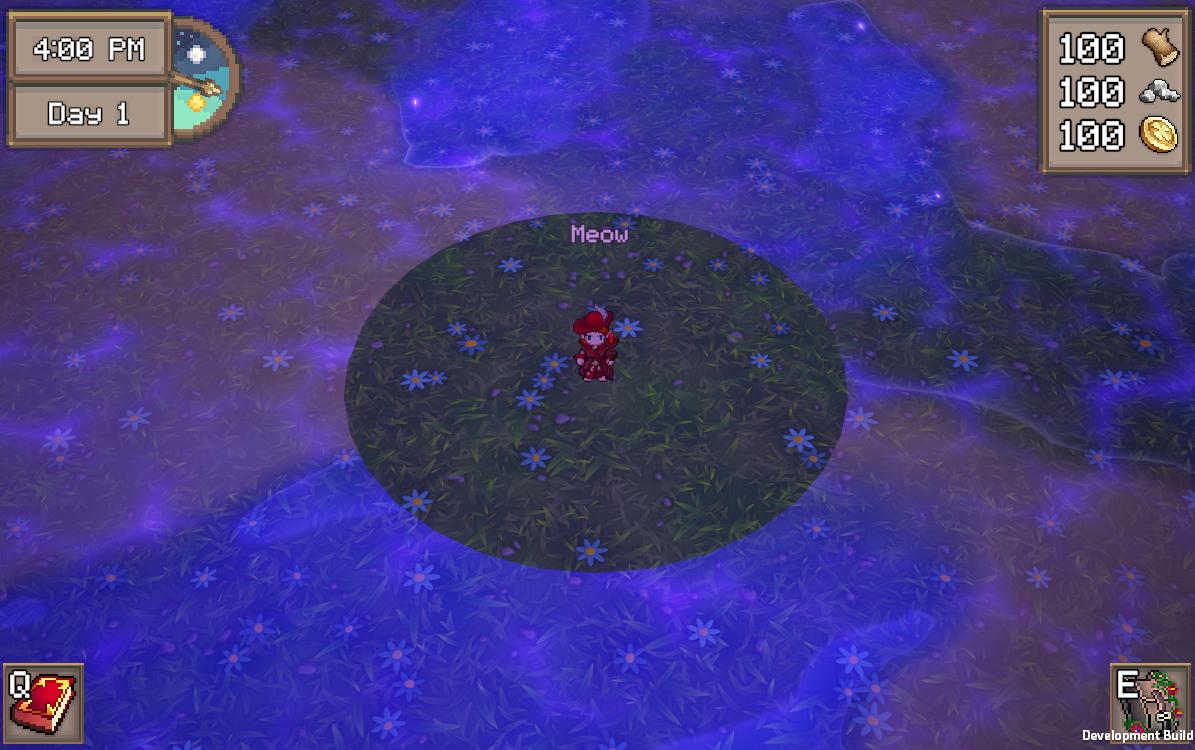
I would assume it's probably simple like pi radius and some sine waves
Upping this !
are there any other ways to do ordering/prevent z fighting than: render queue, vertex displace one on normal? I have a situation where neither of these is working great
Im not sure but I think you can use the sphere mask node in the vertex stage. If it works you can just invert it to get a mask that works inly for the edges
could do sin(atan2(object-space y, object-space x)*number of waves)
(then multiply the object-space position by 1 + 0.1 times that and set that as the new object-space position, or similar)
you can't get light directions in shader graph by default; you can either write a custom node for it or pass them in via script
Do you have any idea about the custom node that could do the job maybe ? I couldn't find much about that :/
It'd be the same as getting the light in normal shader code; apparently accessing WorldSpaceLightPos() and returning it should work? Though it seems that in some shader graph versions (maybe you need a specific rendering pipeline) there's a Main Light Direction node
WorldSpaceLightPos is only a thing for built-in render pipeline though right? Is that what you are using?
How do I make a conditional check of keywords
like multiple or
"keyword1" or "keyword2" etcc
Actually it's a shader created by someone else on amplify that I am looking to "convert" to SG ! I am using the URP pipeline tho !
if it's URP, then these might be useful (built-in functions): https://docs.unity3d.com/Packages/com.unity.render-pipelines.universal@14.0/manual/use-built-in-shader-methods-lighting.html and how to use (some of) them in SG: https://blog.unity.com/engine-platform/custom-lighting-in-shader-graph-expanding-your-graphs-in-2019
Thanks ! I'll take it a look when I'll have to work on it and I'll come back if needed !:) Thanks a lot for your time !
heya, so rn im trying to make a snow shader using a displacement map, and i split the whole terrain into chunks, but at the borders seams started to appear, so i chekced the uv's and for some reason theres a spike at the edges, anyone got any idea why? maybe a precision thing?
this is the uv's code:
void CSMain(uint3 id : SV_DispatchThreadID)
{
    float2 uv = id.xy / resolution;
    uv = (uv + offset) * scale;
    Result[id.xy] = uv.x; //gradientNoise(uv) + 0.5;
}```
Can you show your Dispatch code in C#?
sure, generator:
{
    [SerializeField] ComputeShader perlinNoise;
    [SerializeField] int resolution = 256;
    [SerializeField, Min(0)] float scale = 1;
    [SerializeField] SnowChunk[] snowChunks;

    public void Generate()
    {
        if (!Application.isPlaying) return;

        foreach (var chunk in snowChunks)
        {
            Vector2 pos = chunk.GetGridPos();
            RenderTexture texture = new RenderTexture(resolution, resolution, 0, RenderTextureFormat.RFloat)
            {
                enableRandomWrite = true
            };
            texture.Create();

            int kernel = perlinNoise.FindKernel("CSMain");
            perlinNoise.SetTexture(kernel, "Result", texture);
            perlinNoise.SetFloat("resolution", resolution);
            perlinNoise.SetFloat("scale", scale);
            perlinNoise.SetFloats("offset", new float[2] { pos.x, pos.y });
            perlinNoise.Dispatch(kernel, resolution / 8, resolution / 8, 1);

            Renderer rend = chunk.GetComponent<Renderer>();
            rend.enabled = true;
            rend.material.SetTexture("_DisplacementMap", texture);
        }
    }
}```
chunk:
```public class SnowChunk : MonoBehaviour
{
    [SerializeField] RenderTexture texture;

    public Vector2 GetGridPos()
        => new Vector2(transform.position.x, transform.position.z) / 5;

}```Is the resolution still 256 like the default value?
yep
Ok. What can happen when dividing resolution by numthreads is you get a fraction, which gets floored to an int, meaning you end up with one less threads than you need, so the last few ids won't get processed. But if you're dividing 256 by 8, that shouldn't be a problem.
why would it get floored?
also even weirder is when i dont apply the scale and offset it seems fine
also, if i turn down the resolution to 8, the weird area gets larger:

I mean if the resolution was, for example, 255. 255 / 8 = 31.875, but because it's an integer division, the fractional part is removed, so 31. With 31 * 8 threads, you only process 248 elements.
ooooh got it
could it maybe be something with the sampling?
im using sampleTexture2DLOD on a render texture
I don't think so. To be honest, I'm finding it difficult to understand the screenshots. The glitchy looking Moire pattern is what you want?
nope i think its just an artifact because of the low resolution
Are the two parts supposed to be touching?
You want everything to be a light gray color, but the edges are white?
I'm not really seeing the displacement, but it's also a very zoomed in and cropped image.
yes, so this is what i started with:
there were some weird seams at the edges, so to debug i set the colour and displacement values to the x value of the uv, which then led to the weird flat things at the edges

so this was meant to be just a seamless smooth ramp:

but instead, weird flat bits
What that looks like to me, especially at the black and white edges, is that it reaches 0 and 1, min and max, before it reaches the edge. So it bottoms/tops out, not able to displace it any further.
Is resolution defined as a float in the compute shader?
yes it is
Mm, I think you need to be dividing by 255, not 256. uint3 id will max out at 255, so uv will not reach 1 if you divide it by 256.
I think for the edges to align, you need the edges of the textures to overlap by 1 pixel.
So, Gpu instancing with shader graph doesn't work???
hmm mayb but right now the resolution is at 8 and it's still happening
oh yeah good point
Afaik it can with workarounds (at least in URP, I haven't tested other pipelines). Setup depends what you're doing. I have some info here -
https://www.cyanilux.com/faq/#sg-gpu-instancing
https://www.cyanilux.com/faq/#sg-drawmeshinstancedindirect
this is what it looks like with a resolution and thread size of 2:

the edges are taking up exactly 1/4 each of the area
Aaah that's where I recognized you from! I saw you somewhere and i couldn't figure out where XD
So im still first moving my stuff to shader graph in built in, according to this, it should work in urp and hdrp too (gpu instancing) but my problem is getting the instance ID to be a dif value than 0 https://docs.unity3d.com/Manual/GPUInstancing.html

So I should define the variables using the instancing buffer start , and similar macros
However, what if i do have some global variables? As I understand, having them in the blackboard will break gpu instancing
But even built-in, creating a lit shader graph doesn't have the GPU instancing checkbox
Got it to Work!
ithink what happened is the sampler didnt have another pixel to interpolate with, so it just set it to constantly the edge,so what i did when i sample my uvs i make it a little larger the the uvs will have some padding
Is it normal for Unity to compile shaders like this for 3 hours (Main culprits are Hidden/Lit, Terrain/Lit and Tree_PBRLit)? I've looked around and found very little about it besides for enabling shader stripping... It's a very simple game, and this seems bizarre, any ideas?


I found a post saying I manually need to remove keywords from these shaders, but I didn't even make the problematic shaders, they're native URP
https://i.imgur.com/wGVqL27.png
Having trouble understanding what I need to do here to distort this ellipse with some wave functions. I can run a texture over it with alpha values, but that doesn't really meet my requirements of modifying the values that are already there.
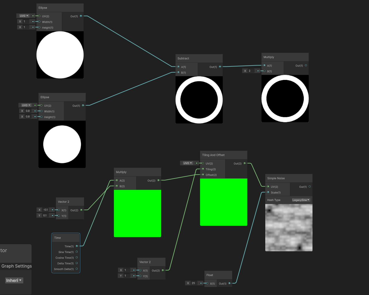
I'm trying to just modify the edges of the ellipse with some distortion then afterwards plug back in the center radius if that's doable
https://i.imgur.com/zWbG1AY.png
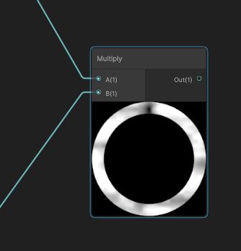
Multiplying would just give me the elipse with the noise being scrolled over it
You need to distort the UVs going into the Ellipse, not after
Ah, ok. I was playing around with that idea but couldnt really get the values I wanted
but now that I know I'll fool around with it a bit more
I'd probably do something like (Noise * Strength + 1) * UV
tyty
https://i.imgur.com/k7pFgYH.png
Was trying some things but going back to your formula here. Without that addition it offsets the ellipse to the top right most corner. The additional integer after multplying the noise and strength helps combat that offset, but the noise still seems greatly focused in one area of the ellipse instead of distributed evenly.
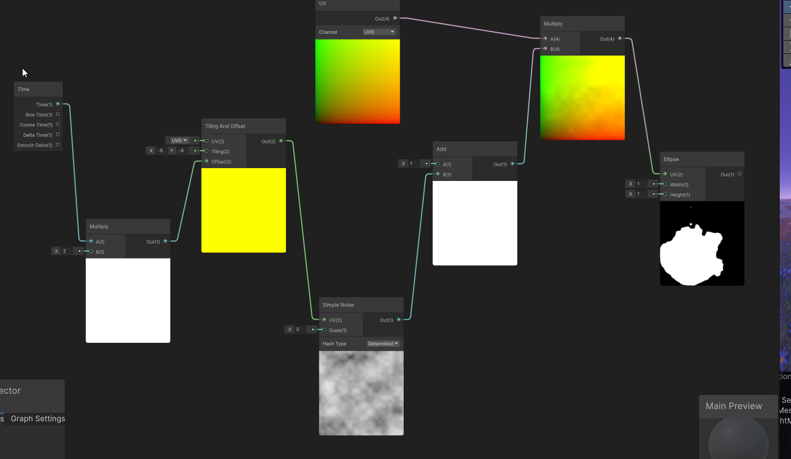
Ah right, I forgot the ellipse was centered at (0.5, 0.5). In that case you need to subtract before applying scaling, then re-offset to center.

Can also subtract 0.5 after the noise so changing the strength only distorts the ellipse rather than changing it's radius too
And if you use a seamless noise texture (instead of Simple Noise), could try using Polar Coordinates as the UV to sample that. Might look neat
https://cdn.discordapp.com/attachments/288887968960086016/1247701867668967475/Unity_0WUPyFFJhv.mp4
Works pretty good. I think maybe I'll look into removing the rotation from inside of the shader otherwise can just use some rotation constraint here. Also, maybe adding some emissions to the edges or something if I can figure that one out. I was thinking some intersection shading, but these both are transparent so I doubt I can do that.
IDk if it belongs here but i downloaded this blood decal and its very bright when theres no light, how do i go about changing that?

Use a lit material for it.


- This is not a lot shader.
- Most lit shaders can be made transparent or use alpha clipping.

Hey, am trying to mask UI using stencil buffer, when am changing the layer of UI element its disappearing from the screen.


These are the properties for my layers


can anyone help me to find reason why its happening.
I would try Queue : Transparent rather than opaque (for the InsidePortal one). If you need opaques too, duplicate it
tried but still same :/
Quick question: shadergraph now has heatmap color mode, but is the color legend documented somewhere?
not finding these colors super intuitive, black < blue < purple < cyan?

I know it was posted here - https://forum.unity.com/threads/2023-3-heatmap-color-mode.1507490/#post-9418109
So I've been trying to learn shader graph properly for the past week, there's one effect I'd really like to work out using a sprite shader in URP whereby the sprite inverts the colour of whatever is behind it. I feel like I am very close, I have tried using Scene Position > Scene Color > One Minus but it only returns the colour of the camera background. If there is a way to sample the pixel behind the sprite that might help?

Perfect that's it, thanks
The Scene Color node only shows opaque geometry (it samples the camera's Opaque Texture) so won't include other sprites which use transparent shaders. But if you can find a way to blit the screen at a different stage (After Rendering Transparents) to your own render target you can pass that as a global tex to sample instead of Scene Color.
Might help - https://github.com/Cyanilux/URP_BlitRenderFeature
(But note shaders that sample that global tex need to be rendered with RenderObjects so they can also be in the After Rendering Transparents event)
Interesting thank you, I did try using 3D objects behind and it works fine.

This could be done very cheaply with a blend operation, but I don't think that's possible to configure in Shader Graph.
Unity Forum
Hey guys, I thought I'd share this simple transparent shader. It inverts the colors of anything behind the mesh to which it is applied. It also has a...
Hey everyone! I ran into an issue while trying to implement an occlusion shader and would love some help 🙂
I'm working on a 2D game in Unity and I'm using URP for the render pipeline with Transparency Sort Mode set to Custom Axis (Y-Axis) so that the characters can walk both in front and behind Obstacles based on the Y position. I wanted to implement an occlusion shader so that the pixels of a character behind an Obstacle would render with a different texture (see first image).
To achieve this I set all the Obstacles to use a shader that has a Stencil Ref 1 Comp Always, and a Render Feature for the characters that checks the Stencil value and if it equals 1 overrides the texture with a special Occlusion Texture that I made. It works fine when a character is behind an Obstacle. But it unfortunately also works when a character is in front of an Obstacle (see second image). I'm not sure but could it be because I'm using Custom Axis as the Transparency Sort Mode, so the renders of the elements are sorted dynamically based on their Y position (?)
I don't know if the Stencil test is the right approach for this scenario and I would love to hear your ideas on the matter. Thanks nonetheless ❤️
P.S.: I'm still very new to shading so I'm sorry in advance if it's a trivial question 😅


Usually when I do this stuff it's by using depth in 3D space, but for 2D that seems quite complicated. Usually you compare by depth values then use stencil comparison, but here you don't really have that, only the camera sorting axis between the two sprites.
So in place you do need that sorting information and use it over the depth value.
Not too sure if you can do it all inside of the shader since a lot of this is scene-level sorting, so you may have to do it via script unless someone else has some better suggestions
Hey, I need the Built-In render pipeline projector component in URP. I tried using the decal renderer feature, but it doesn't work, I'm trying to make a flashlight that doesn't use actual lights.
First of all thanks for the answer, I appreciate the effort <3. What would be your way of approaching the fix via script?
Brute force approach would just compare against positions and swap out stencil/sorting values (or layers if you're doing it via render objects)
You mean comparing the character position and any obstacles in its proximity to check if it's in front or behind anything?
Right, your own comparison method on where each object is. But again, this is just an idea I've little research about.
Usually I do 2.5D stuff so I get the privilege of having that depth information to use.
Yeah true, but thanks still 🙂
https://i.imgur.com/xJjrck2.png
Basically the same thing you're doing with the render objects
neat, is it your work?
Was for a jam but a little over due lol. Rather iron some stuff instead of releasing something half-finished
For the life of me, I cant find a normal base outline shader that works on the Oculus Quest (Meta) and am using URP for my game. Does anyone have any suggestions?
hello my sprite fills up the empty space like this when i add a shader what do i do?

In shader there's the unity_ObjectToWorld and unity_WorldToObject matrices, right?
So uh, I'm meant to pass these two matrices, I'm basically writing the CPU side for rendering, thought that this question will be related to shaders-
Do these two matrices include rotation and scale?
I've only touched upon those two matrices a few days ago, when trying to write my own shader, and honestly? Idk what they really do yet '^^
Is that the same as Transform.localToWorldMatrix?
The naming suggests that they're probably the same thing...
Oh, yep! Haha I didn't realize how close I was to adding scale and rotation to my renderer 😂
Literally just change Matrix4x4 matrix = Matrix4x4.Translate(renderer.transform.position); to Matrix4x4 matrix = renderer.transform.localToWorldMatrix;
Yeah, I have managed to make a working invert shader in code but not shader graph
Why does this node have no input or output?
Unity 6 URP 17.0.3


Solution: Reopen the engine.
Might have collapsed the ports on the node. If you hover over there's usually an arrow/triangle in the top right corner of each node that toggles unused ports
Yes, I thought so too, but nothing changed when I turned it on and off 😄
Ah okay, just bugged out then
quick lightmap specular occlusion tip.
I've seen this in Bakery and unreal. I quickly did this in the shader graph before adding it deeper into the URP.


nice
the one thing that unity DESPERATELY has needed to add by default since the inception of the PBR standard shader
specular occlusion is very underated
what does this mean? Im new to these things

it really tells u exactly what to do
have u looked in the graphics settings like it suggests?
@kind juniper i spent all night and day trying to figure it out and i just couldnt. but i did find that if i change the shader to (image attached) it works like a charm

I am trying to draw to a render texture, and I want to make that render texture have a transparent background, but I have a problem where it seems that Shader Graph shaders don't write out to the alpha channel for some reason. Regular shaders write out just fine, but Shader Graph shaders don't.
Repro steps:
- Create an empty project (2022.3.20f1) with the built-in renderer
- Package Manager -> Add the Shader Graph package
- Create a new Render Texture asset. Change none of the properties on it
- Create a Camera in the hierarchy. Set its Target Texture to the Render Texture from step 3, set its Clear Flags to Solid Color, and set the alpha of the Background color to 0
- Create a new Shader Graph shader, using Buitin -> Lit Shader Graph
- Set the Shader Graph's Surface Type to Transparent, and verify that its alpha channel output is set to 1 (the default)
- Create a Cube in scene that is inside the frustum of the Camera from step 4
- Click on the Render Texture and look at it in the inspector. Click on the R, G, B, and A channels to see the cube rendered in each color channel
- Apply the default Material for the Shader Graph (from step 5) to the Cube from step 7
- Click on the Render Texture again and look at it in the inspector. Click on the R, G, B, and A channels to see the cube rendered in each color channel
Expected:
The cube shows up in the R, G, B, and A channels, in both steps 8 and 10
Actual:
The cube shows up in all four channels in step 8. That's fine.
But in step 10, it shows up in the R, G, B channels, but it DOESN'T show up in the A channel
Is there something I'm missing, or should this be working?
(note: this reduced repro is a bit nonsensical on its own, but that's cause it's minimal. the minimal repro doesn't have any actual display of the result of the render texture in scene. In my actual project I am using the render texture in a scene and it still doesn't draw properly unless I set the render texture camera's clear color to have an alpha of 1.0 [255]. and that of course makes the entire alpha channel white, which is not what I'm going for)
It might be better to create your own shader for decals, instead of using the UI shader(who knows what kind of overhead and potential bugs in your setup it would have)
Your absolutly right i didnt think about that, ill look into making my own shader.
huh. it looks like if I spit out the generated code, copy it over an older style shader, and edit it so the "BuiltIn Forward" pass has a ColorMask of RGBA instead of RGB that solves my problem.
Is there a way to do this in the UI, or do I have to forego an editable graph to get the results I'm looking for?
oh I see. it's just hardcoded into BuiltinTarget.cs
Hey everyone, quickie question
I'm working on something for a gamejam, and i have a conveyor belt that uses a shadergraph based shader, that just scrolls the texture, and the player can start and stop this belt, which changes the speed value in the shader
My issue is, that sometimes when the belt stops/starts, the texture jumps (my best guess to why it happens is that since the speed gets set to 0, the offset will be 0 as well, since it's multiplying the time by the speed, which wont match up with the current pos the belt was on)
Is there an easy way to fix this issue? The only idea i have for fixing it is setting the offset each frame from a script, so that it doesn't rely on multiplying the time with something to get the movement, but i feel like rewriting shader parameters each frame would be awful for the performance
Ended up implementing the script based approach, and the performance seemed to stay exactly the same, so ig it's solved
Is it possible to change a HDRP shader to URP?
it turned pink

and its a custom shader
and when i open it it becomes a script

any methods to turn in into urp compatible manually?
how do i make a custom shader graph node???
have you tried the Custom Function node?
no
You can also create a Sub Graph if you prefer to create the node with shader graph nodes (as opposed to HLSL code in case of Custom Function)
id rather use code
This is a surface shader, and shouldn't even with with HDRP/URP.
The best way to do it would be to make this shader with shadergraph
Use the Custom Function node then. The docs has basic example of how to use it: https://docs.unity3d.com/Packages/com.unity.shadergraph@6.7/manual/Custom-Function-Node.html
ty
alright thanks!@
How do you get the texel size of any texture?
Shadergraph or code ?
Unity shader can also use the {TextureName}_TexelSize macro :
{TextureName}_TexelSize - a float4 property contains texture size information:
x contains 1.0/width
y contains 1.0/height
z contains width
w contains height
(.shader is for the shaderlab language, where you also include CG or HLSL code)
ah yes - that macro worked before - the only place I was unable to use was in a PostProcess for the _CameraColorTexture_TexelSize, not sure if I missing the macro in includes
Hi guys, i have a custom shader work fine with SRP, but now i've tried to convert it into URP but it's dont work. Can any one help?
My Shader
Hello, I exported a model from blender to unity with my configs that works normally with other models but for this one when a face is deformed by a bone there is a reflexion/shading bug that appear with every materials and only when face is deformed in a certain rotation. I'm in URP and the face is flat shaded, I tried with different geometries technics but same result. Anyone know how to fix this? (please ping me for the answer, thx)
You need to recreate it and select the URP shader, not the builtIn.

we can't convert it?
idk any solution to convert but maybe just copy-pasting nodes will work
it's a custom shader not shader graph

If it's manually coded I can't help you with it
While it is technically possible to write shader by code for URP, it is not straightforward as with built-in and the surface shader syntax, so it is recommanded to use shadergraph.
If you don't want to redo to full shader with node, you still have to possibility to use a custom function node in the graph to do all the logic.
I tried to make a sun sun that is always in the background no matter where the object actually is by putting it back in the render queue. It works fine without a Skybox but when I add one, the skybox seems to cover it up. Does someone know why that could be and how to change it?


What render queue value are you using for the sun?
2000
2000 is the default render queue for geometry.

Is it using a custom shader?
yes

I also used it for outlines on some objects. It basically makes a bigger copy of the object and renders behind it
I fixed the problem. I changed the Queue Control to auto and the Sorting Priority to -50. Then I changed the Render Queue of the buildings to 3000, since all the other objects seem to be in 3000 on the render queue. It seems to work now.


where do i get a render pipeline asset
You can just create one
how
Assets>Create>Rendering>
ok i created one but there are lots of problems.

Are you sure you're following all the steps for installing URP?
Instructions can be found pinned in #archived-urp
i didn't follow nothing, imma follow them now, thx
nvm i solved all the things

i have this graph that spawns one circle that goes from the inward out like a shock wave, is there any way to multiply this circle ?
so that there would be multiple rings shooting outwards?
im shader graph noob just following tutorials here so help would be appreciated
Hi, Does HLSLPROGRAM support built-in RP? If It does, which file should I include that equivalent to UnityCG.cginc?
Anyone know how I can make massive swells using the new HDRP water system? I've messed with the water settings, but I can't seem to make anything really crazy. I'd love to make some massive waves
I dont think you need to include anything
https://docs.unity3d.com/Manual/SL-ShaderPrograms.html
except if you are making post process effect
Thanks for replying. But since Unity doesn't use CG anymore, will UnityCG.cginc be stopped supporting in the future?
I sure hope not 😅
Put the Length through some function that makes it change sign multiple times (e.g. multiply by twenty, then Sine)
And add the time to the length instead of the smoothstep
anyone done image filters in a shader graph? i.e. reading a 3x3 section of pixels and apply a formula. The graphs seem underdeveloped to do this but I figure a custom node should handle, just have not done much in that area
also using depth in shader - linear01 or raw? What are benefits or either?
Split node
Use #✨┃vfx-and-particles for vfx-graph questions
ok
omg thanks a lot that worked really well!!! even though i dont have the time rn i do want to learn shader graph really bad in the future, do you have any learning source for that?
highly appreciate your help
with a custom function node how do you access the screen's color or normal buffers?
(shadergraph)
Tyring to get RenderMeshIndirect working but Im only getting shadows in one of the items? Im not sure why, im using shader graph also

But I dont know even what to send here to test
here's for example the render params
RenderParams renderParams = new RenderParams(){
    camera = cam,
    material = lod.materials[lm],
    matProps = propertyBlock,
    receiveShadows = true,
    shadowCastingMode = ShadowCastingMode.On,
    worldBounds = terrain.meshResult.mesh.bounds
};
how do I use standard unity shading in my custom shader that is NOT a surface shader? I have separate vertex and fragment functions and all required properties of a surface like material properties, normal etc.
someone who knows how i can work around the issue where you can only use 16 texture samplers in 1 shader in hdrp?
This is hardware limitation. Why do you need so many?
Reuse samplers from other textures or use inline samplers (in shadergraph that's the Sampler State node)
heya, i know its possible to pass a buffer of structs to a compute shader, but is it possible to pass just one?
Brackeys has some shader graph tutorials, also just mess around with making things and you learn as you go
vertex painting
ill look into that, thx
Anyone here know how to animate UV Tile Discard in Unity with poiyomi shaders? I cannot for the life of me remember how I animated the UV tile discard before. : ( When I hit record and try to animate it like how I did for the hat no properties show up at all.

A buffer can have zero, one, or more entries. So sure.
You could also use a CBUFFER I suppose.
Hello I am currently following Japser Flick's compute shaders tutorial(I'm not aware of how well known catlike coding is) and this is my first time writing shaders, I get a Kernal Index (0) out of range error. I looked this up and apparently that means the shader didn't compile. Also in my project the compute shader appears as a text asset with a compute shader inside of it? I haven't seen this anywhere else and am wondering if it is related to my error and for some reason unity isn't recognizing the shader as it is supposed to. When I look at the compiled code, theres not really anything in there it says: *** Platform Direct3D 11: no variants for this platform (no compute support, or no kernels)


Kernal and kernel is not the same thing
ah thank you, I take it there is no linting for shader code
Intellisense you mean? You can install the hlsl extension for visual studio, but it's not perfect

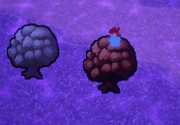
someone who knows why my red mist is making my leafs shader very weird?

Spline, fit mesh to spline, (or ideally generate mesh at runtime to fit spline of any size) shader on mesh to make translucent and glowy
Need to know more. What rendering pipeline is this, what does the material in question look like, and how are you doing your mist
hdrp, material is a custom shader and the mist just has a color


its a lit shader btw
i have a skybox that i'm trying to have a day-night cycle by simply shading from a day cubemap - night cubemap. I want it to also have a sunrise and set. So, i have two add nodes. one does sunrise-day cycle, and the other does night-sunset cycle. how do i add them together?
im using shadergraph btw
yall plz-
idk if im right heer but my problem is that my road is pink bc of the material and idk how to fix im usung the road from the Easyroads 3D Free v3 asset and its pink. i dont know how to fix

Hi. I'm new to shaders and started out trying to just follow along with a YouTube video creating a toon shader.
For whatever reason there seems to be no effect on my objects when I apply the material to them. They are just one singular opaque color, as if lighting is not being taken into account?
Unsure of where to start with deducing what is wrong. I'm using the built-in pipeline and the attached image is the first few nodes of the graph (I can post more if needed; or link the video I followed). Would appreciate any help on this.

how could i make it so that this transparent image (the word test), so that it inverts against the animated background?

Alpha = -1
Okay. I've narrowed it down and it really does seem to be that Main Light Direction is not working. I just did the dot product of that and the normal and the object is just opaque black as if there is no light.
Does Main Light Direction not work with the built-in pipeline?
kinda yeah, it extracts the text but is showing the transparent parts

Hey I am having what should be a relatively simple issue, but no matter what I try it's not working.
I simply want to render my mesh behind ALL geometry with my shader. It should always render in the background, right in front of the skybox.
I have tried:
- Setting the ZTest Mode to Lesser
- Setting the Render Queue to 0 or 1
- Messing around with the Stencil Buffer (I could probably test more with this)
No matter what I do I can't get it to work. I am on URP 2022.3.22f1
I have literally no issue having the geometry render on top of everything, but having it render behind everything isn't working.
Okay Stencil Buffer works if you use Greater or Equal
problem solved 😅
Hello everyone 👋
I need hep with bliting one render texture's depth buffer onto another render texture's color buffer. Is there anyone who has experience with this and could help, thank you 😃.
⬆️ If someone can help me with this, I can pay for your time
Here is more context: https://discussions.unity.com/t/getting-depth-from-rendertexture/365259
the mentioned post in this post explains why I need it
So starting from answering your second question on that page:
It probably depends on the graphics API. Assuming we're talking about dx11/12, a depth buffer is basically a separate texture that is bound to the pipeline each time you render something. You can have as many depth textures as you want, but only one can be bound during a draw call.
Now, unity obviously hides all of this low level stuff, so it's hard to say how exactly it coincides with the high level render texture API, but my guess is that internally unity creates an additional texture(depth) for a render texture if the depth is required. Unity doesn't seem to provide direct access to it in the shaders though. However, assuming you have a camera that only renders to that render texture, you can use it's scene depth(a node in shader graph) and it would contain the same data as the rt depth buffer.
Assuming the above is correct, you can use that depth node in your shader to access the depth data and do whatever you want with it, whether it's to render it into into a texture or use directly for whatever logic you need.
How do I get outlining work on HDRP? Specially the quick outline asset. I have only focused on programming game mechanics so I have 0 experience with shaders. I want it to hook it to my interaction script where I can give a highlight effect to interactables.
Assuming we're talking about dx11/12, a depth buffer is basically a separate texture that is bound to the pipeline each time you render something.
isn't that so like... everywhere except D3D9 (where depth buffer was not a texture)?
Hey Everyone, I'm trying to implement a Pixel Art Shader using an Unlit Shader Graph. Does anyone know where I should start looking into why my output is not showing up?

Most commonly project not using URP, yet the Target is Universal
Switch the project render pipeline, or switch the graph target
Thanks for that.
I have verified the rendering pipeline, now the output is blank? I trully appreciate your help

Sure you followed all the instruction for setting up URP, including quality levels?
Absolutely not. I do not know what I am doing and I'm following outdated Youtube Tutorials and ChatGPT
Proper instructions pinned in #archived-urp
🤣 Thanks @grizzled bolt
Donno. Haven't had the chance to deal with d3d9. I only know a bit about d3d12(and 11 since they are somewhat similar afaik) and some consoles graphics API, since I'm dealing with them at work recently.
does somebody know why it wont let me convert this to a sub graph?

I'm having a problem with my shader - it doesn't calculate values correctly when Y is below 0. I tried to make the pattern first in desmos becouse i needed to find out what the equation was, and there it looks fine.


Values below 0 just f up the shader

Note: If the input A is negative, the output might be inconsistent or NaN.
https://docs.unity3d.com/Packages/com.unity.shadergraph@10.2/manual/Power-Node.html
well that sucks
You can just ABS the value before inputting it into the power node
If you really need power there
multiplying number with itself manually is actually faster and fixes that problem :)
(btw, it's actually a limitation of the underlying shader languages rather than the shadergraph itself - they sacrifice support for negative numbers in cases where they would be valid for a slightly faster pow() implementation)
thanks so much! Tho my wave shader doesn't work either. Does modulo have similar issues?


its behavior is well-defined, but it gives negative values if you give it a negative argument
ok so abs() kinda fixes it...

it gives negative values on the opposite side :)
let me launch Unity editor and i'll show an alternative
yeah, i got that.

one way to do it how you expect

TYSM!

i actually figured that the alternate solution would be like this but i waited if you wouldn't present a better one
builtin modulo basically compiles down to HLSL fmod builtin function, which then in turn compiles down to something similar except with truncate instead of floor :)
is there a plugin or a way to convert shader graph into shaderlab
ive already tried pressing view generated shader on the graph inspector but it didnt work
guys i just started learning shaders and i just created a blank unlit shader in hdrp but for some reason its completely ignoring the z buffer
like everything is being rendered in front of it

help would be appreciated
thx in advance
the color is meant to be black also the zwrite is turned on
the areas where there is another object under that pixel seems to be the only area where it renders correctly
the sky where depth=1 kinda renders correctly but the water fails (hdrp water does not write to depth buffer at all so this is probably an issue with the fog)
ok no nevermind it never renders correctly anywhere on the screen
wait no that was something else
if the color is red this is what happens

ztest is lequal btw
alright i found how to solve it, set the renderqueue to transparent
ah, your clouds shader must be rendering after (thus on top of) your opaques
if your clouds are always far away relative to the scene, you could render the background and then render the foreground onto that texture
Hi! I'm using Cyan include file to draw instances with gpu instancing. https://www.cyanilux.com/faq/#sg-drawmeshinstancedindirect. The data that is written into the matrix is relative to the world. But the items appear in completely wrong place. Seems to be something related to the bounds, but I can't figure out how to make them right
Is there any way to not use the world bounds?
this is making me go nuts
This piece of code works, put the positions are not in the right place
#if UNITY_ANY_INSTANCING_ENABLED
    // Updates the unity_ObjectToWorld / unity_WorldToObject matrices so our matrix is taken into account

    // Based on :
    // https://github.com/Unity-Technologies/Graphics/blob/master/com.unity.shadergraph/Editor/Generation/Targets/BuiltIn/ShaderLibrary/ParticlesInstancing.hlsl
    // and/or
    // https://github.com/TwoTailsGames/Unity-Built-in-Shaders/blob/master/CGIncludes/UnityStandardParticleInstancing.cginc

    void vertInstancingMatrices(out float4x4 objectToWorld, out float4x4 worldToObject) {
        InstanceData data = _PerInstanceData[unity_InstanceID];

        objectToWorld = mul(objectToWorld, data.m);

        // Transform matrix (override current)
        // I prefer keeping positions relative to the bounds passed into DrawMeshInstancedIndirect so use the above instead
/*         objectToWorld._11_21_31_41 = float4(data.m._11_21_31, 0.0f);
        objectToWorld._12_22_32_42 = float4(data.m._12_22_32, 0.0f);
        objectToWorld._13_23_33_43 = float4(data.m._13_23_33, 0.0f);
        objectToWorld._14_24_34_44 = float4(data.m._14_24_34, 1.0f); */

... Next stuff
    }
#endif
However, uncommenting that commented part, makes the unity_InstanceID no longer increase, wtf
The data is correct, since manually setting a 5 or 30 i get the expected result, but why does uncommenting that give me weird results?
I'm gonna ping @regal stag since they probably know what's going on (because the code is theirs XD)
Perhaps you just want objectToWorld = data.m;? I'm not sure
that's what I thought too, but it seems that changing that line makes unity_InstanceID always become 0
It's super weird. Because manually changing it i can see that the data is setup correctly
yeah so im still testing this in and out, but setting it manualy for somereason breaks it?? im confused
    void vertInstancingMatrices(inout float4x4 objectToWorld) {
        InstanceData data = _PerInstanceData[unity_InstanceID];
        objectToWorld = mul(objectToWorld, data.m);
        objectToWorld._11_21_31_41 = float4(data.m._11_21_31, 0.0f);
        objectToWorld._12_22_32_42 = float4(data.m._12_22_32, 0.0f);
        objectToWorld._13_23_33_43 = float4(data.m._13_23_33, 0.0f);
        objectToWorld._14_24_34_44 = float4(unity_InstanceID,unity_InstanceID,unity_InstanceID, 1.0f);
this doesn't fill unity_instanceID
this ends up flat in the ground
        InstanceData data = _PerInstanceData[unity_InstanceID];
        objectToWorld = mul(objectToWorld, data.m);
        objectToWorld._24 = unity_InstanceID;
so it retrieves the data correctly, and at the same time instance id is 0
Hi hol, I have discovered an issue with my outline shader. I am currently attempting to make items in the players hand render in front of objects to avoid wall clipping. I am using the DrawRenderersCustomPass in HDRP to render the objects on top. But I am experiencing an issue where the edge detection is not detecting the objects at all, video here: https://streamable.com/avdvdo.
At first I thought this was mainly caused by the objects being fully rendered in the BeforeTransparency injection point. But, I just checked if rendering outlines AfterPostProcess fixes it and it doesnt, infact the outlines shader acts like the objects arent there, video here: https://streamable.com/4xbq93.
Are they writing depth? I'm gonna be scarce today
They are writing depth.

My outline shader also detects normals, so they should be detected.
Ya'll I got the purple problem >_< I imported the asset from unity asset store and both my project and it are URP I'v reimported it a few times but to no avail any suggestions?
Check the shader. Does it have any errors?
I tryed to open the shader and everything went laggy and it said failed to create rendered texture
I didn't mean that you should open it. Just look at the inspector. But failing to open it could definitely be related to the problem too
do you have any suggestions?
Start with providing more details. As it is now I barely have a clue of what's going on on your side.
Ok so bellow is what im working with its the material for an explosion all maps such as the normal map and base map are fine its just the material that's bad if you put the prefab in the game you can tell theres an expolation and the explostiongoes off because theres a ball of light but I big purple square blocks most of it.

This looks like a unity urp shader, so if it's pink, it means that you don't have urp setup correctly.
Should I use the render pipeline converter?
I have alot on this project I wouldn't want to lose and its not reversable
I think im going to make a copy and send it
No. Make sure you have the render pipeline asset assigned in the correct places(graphics and quality settings in project settings)
Hey friends! I'm very new to shaders, trying to use an asset I bought for camera-based distance dither fading. It seems to work fine as is, but my character has some alpha on the main texture that i'd like to keep. As I understand, this shader takes over alpha of the material to perform the fade. Is there a way I can still preserve original base map's alpha as well? Left is the original, right is the fade shader, you can see some unclipped textures around the ears.


I f**ked up man. Both were assigned to anything so I assigned them both to URP and everything turned purple and started doing weird things so I reverted back to both being none and some stuff is still broken

That means that you were not using urp initially. When you switched to it, some of the materials probably auto converted to urp, while some stayed the same. Then when you switched back you still have some urp materials and some nom urp.
You'll need to go through each material that is pink and make sure they use a shader compatible to your render pipeline.
trying to remove this effect from objects in my scene so I can dither based on shadows instead of just having it applies everywhere, does anyone have a good grasp of how to do so? cause currently based on where the camera is, it changes colors or adds more layers, but I don't want the color to change, just the amount of dithering based on luminence


urp-
something more like this, but with color

depends on how you apply the shader, is it post process? If it is, you can either use stencil to define which part of the screen get the effect, make/rewrite to the post process shader into surface shader
if you bought it, I think you might get better result by asking the seller on how to integrate/modify it.
But I think you can also multiply the fade(1) node with image alpha before connecting it to dither node
will give it a shot, also emailed them, hope they are responsive 🙂 thanks!
does anyone know why this imported shader is showing up as white?

Hard to say without looking at the shader documentation and/or code
Does anyone know how to make a waterish shader on a mesh?
how would i make something similar to this on a mesh?

all the shaders online work on a plane
take the usual stuff for a water shader, and then when the normal is not (almost) vertical start adding foam and whatnot to make it seem like it's flowing
The vertical and horizontal walls don't necessarily have to use the same shader
So i guess my problem is how im setting up those matrices. How can I create an object to world matrix, using a position?
trying to create it like this
    void vertInstancingMatrices(inout float4x4 objectToWorld, out float4x4 worldToObject) {
        float3 position = _PerInstanceData[unity_InstanceID];


        objectToWorld._11_21_31_41 = float4(1, 0, 0, 0);
        objectToWorld._12_22_32_42 = float4(0, 1, 0, 0);
        objectToWorld._13_23_33_43 = float4(0, 0, 1, 0);
        objectToWorld._14_24_34_44 = float4(position, 1.0f);

        // inverse transform matrix
        float3x3 w2oRotation;
        w2oRotation[0] = objectToWorld[1].yzx * objectToWorld[2].zxy - objectToWorld[1].zxy * objectToWorld[2].yzx;
        w2oRotation[1] = objectToWorld[0].zxy * objectToWorld[2].yzx - objectToWorld[0].yzx * objectToWorld[2].zxy;
        w2oRotation[2] = objectToWorld[0].yzx * objectToWorld[1].zxy - objectToWorld[0].zxy * objectToWorld[1].yzx;

        float det = dot(objectToWorld[0].xyz, w2oRotation[0]);

        w2oRotation = transpose(w2oRotation);

        w2oRotation *= rcp(det);

        float3 w2oPosition = mul(w2oRotation, -objectToWorld._14_24_34);

        worldToObject._11_21_31_41 = float4(w2oRotation._11_21_31, 0.0f);
        worldToObject._12_22_32_42 = float4(w2oRotation._12_22_32, 0.0f);
        worldToObject._13_23_33_43 = float4(w2oRotation._13_23_33, 0.0f);
        worldToObject._14_24_34_44 = float4(w2oPosition, 1.0f);
    }

    void vertInstancingSetup() {
        vertInstancingMatrices(unity_ObjectToWorld, unity_WorldToObject);
    }
and doesn't seem to work
Only one tree appears on the corner

yeah but the thing is
no no
that's the problem
the assets and libraries all use planes but i'm wondering if that's for a reason
Flat water shaders are much easier to make, allowing for some shortcuts and optimizations and probably suit 80% of use cases
what would i have to change to adjust for the mesh?
Impossible to say, entirely depends on how the individual shader is designed
I'm having trouble using vector arrays with urp. Searched a lot online for a solution but it seems that the vector arrays in the shader just aren't being set. Are there any quirks I should be aware of?
I've confirmed that the array I'm passing in has values set. I'm not declaring the vector array as a property, but instead declaring it within hlslprogram
I've even tested with a smaller simpler shader to confirm, and even that doesn't work.
Script for setting the array: https://hatebin.com/mhduulbnhp
Shader code: https://hatebin.com/dsmatqgdvf
super newbie question, I'm trying to convert a few nodes in urp litshader into a shadersubgraph but it doesn't do anything nor create any files, anyone knows what I'm doing wrong?
Hm alright, thank you
I'll try to make something and if it doesn't work I'll ask it here.
I rarely use setvector4 but from my few experience withit I dont recall any problem.
Are you sure you want to add the vector4[0] value with the maintex? If the color is white, anything added to white will just return white
^ yea to add to this, might be better to test with just return _VectorArray[0]; - and other indices (Index 0 would be black based on your c# script)
Could also try setting with Shader.SetGlobalVectorArray, iirc there is a quirk where the SRP batcher doesn't play nice with per-material arrays iirc, though unsure if that applies here as the shader doesn't look like it's srp-batcher compatible
If the right-click convert isn't working I'd manually create a SubGraph asset and copy/paste the nodes in
Hi Shader Graph has a branch node but it is kind of backwards - you pass in 2 alternatives and it gives out one or the other. What if you want to do if, else in the graph? Is that not more optimal or does the shader avoid calculating both alternatives for a branch?
You can chain multiple branch nodes together if needed. SGs Branch node uses a ternary (bool ? a : b;) which afaik in hlsl always executes both sides, it just discards one
ok, this is the annoyance. I guess shader code does not really skip anything, just uses only one result
Kinda yeah as gpus run in parallel. There are ways to properly branch (i.e. [branch] if() in a Custom Function node), but that's only useful if groups of nearby pixels share the same side, otherwise I think it can end up being more expensive
Thanks! that worked, took me a while to understand how to manually add the output and input but I figured it out
Why can't i declare and multiply by a matrix4x4 inside a custom function in a shader graph?
Aka, this doesn't work when used on a custom function
float4x4 _ObjectToWorld;
void TransfromPosition_float(in float3 objectPosition, out float3 position){
    position = mul(_ObjectToWorld, objectPosition);
}
but declaring the matrix in the blackboard and manually multiplying it does
im trying to understand matrices to debug my problem of instance ID and this is making extremely hard to debug and test out. I have no clue why sometimes instanceid has a value diferent than 0 and sometimes it doesn't
Correct matrix multiplication with a position looks like this:
position = mul(_ObjectToWorld, float4(objectPosition, 1)).xyz;
Okay, alright! this does work
Alright, taking this into account, this node correctly applies the transformation matrix into the position
void TransfromPosition_float(in float instanceID, in float3 objectPosition, out float3 position){
    InstanceData data = _PerInstanceData[instanceID];
    position = mul(data.m, float4(objectPosition, 1)).xyz;
}
However, overriding the ObjectToWorld matrix to make it happen by default doesn't, any idea why would that be?
    void vertInstancingMatrices(out float4x4 objectToWorld, out float4x4 worldToObject) {
        InstanceData data = _PerInstanceData[unity_InstanceID];
        objectToWorld = data.m;

        // Inverse transform matrix
        float3x3 w2oRotation;
        w2oRotation[0] = objectToWorld[1].yzx * objectToWorld[2].zxy - objectToWorld[1].zxy * objectToWorld[2].yzx;
        w2oRotation[1] = objectToWorld[0].zxy * objectToWorld[2].yzx - objectToWorld[0].yzx * objectToWorld[2].zxy;
        w2oRotation[2] = objectToWorld[0].yzx * objectToWorld[1].zxy - objectToWorld[0].zxy * objectToWorld[1].yzx;

        float det = dot(objectToWorld[0].xyz, w2oRotation[0]);
        w2oRotation = transpose(w2oRotation);
        w2oRotation *= rcp(det);
        float3 w2oPosition = mul(w2oRotation, -objectToWorld._14_24_34);

        worldToObject._11_21_31_41 = float4(w2oRotation._11_21_31, 0.0f);
        worldToObject._12_22_32_42 = float4(w2oRotation._12_22_32, 0.0f);
        worldToObject._13_23_33_43 = float4(w2oRotation._13_23_33, 0.0f);
        worldToObject._14_24_34_44 = float4(w2oPosition, 1.0f);
    }

    void vertInstancingSetup() {
        vertInstancingMatrices(unity_ObjectToWorld, unity_WorldToObject);
    }
Hello, how can I make a zigzag material which I can apply to this line using shadergraph?

guys i might be dumb because im just starting out with shader programming but i can't for the life of me figure out why this isnt working
ive got a very simple shader that just maps the uv's y value to the color in a lit hdrp shadergraph

but for some reason the output is only 2 colors

how is this possible? shouldnt it be a smooth gradient from white to black?
any help would be appreciated
also in the material preview it renders how i would expect it to

ok so the issue is something with probuilder because i made the plane with it and the shader appears to work as it should on a regular old plane
either way imma go to bed (its 22:09 here)
if any1 has any solutions pls dm me them thx in advance
Is there a way to conver the Shader into Shadergraph? without recreating it manually from scratch?
Bump, zigzag shader
That looks gorgeous, did you make it ? Or is it an asset pack maybe ?
I have a shader where I'm taking the result of TransformWorldToHClip and offsetting the Z value, This works perfectly to push a mesh towards or away from the camera without changing it's shape. However, if the near clip plane is modified at all, the offset amount also changes. How can I make this offset be clip plane independent?
nvm, figured it out
It's from skylanders spyros adventure :))
Hello there ! Might be a simple thing but I can't figure it out 🤔
I've a distortion effect but I can't clamp my UVs. Am I wrong in the approach ?


Looks good to me, what's on the left ?
You can try setting the texture itself to clamp
yo need anyone to teach me how i start dm me
can u teach me some things? @kind juniper
🥺
No. Check the server rules #📖┃code-of-conduct and #854851968446365696 on how to ask questions properly. If you just need learning resources provide more details on what exactly you want to learn.
where can i ask questions
About in every channel of the server, deppending on the subject
I hope it's readable ahah

i wannna make a game, need to learn some things like variables
That's would more be for #💻┃code-beginner then I guess. Unless if specifically about shader variables ?
But the discord is better to answer specific questions, I feel like you'd better go follow some tutorials first.
alr thx
The clamp node (or a saturate node) should have takend rid of this tiling.
It's not easy to notice, but if I squint very hard on the small texture preview on the left of the sample node, I think I can see some white pixels on the right, is the effect maybe offset ?
That's the point, I don't see any offset in here, that's why I don't understand why there's one 🤔


IT's almost as if the clamp node isn't doing his job ...
What if you use a saturate node instead ?
Are you using a texture transform on the texture property itself maybe ?
Same result. If I multiply my noise (intensity) by 0, offset is going away
As Yggdrazyl also mentioned have you tried changing the wrap mode on the texture to Clamp rather than repeat?
I'm sure it's possible to clamp uvs manually but if you don't need the texture to repeat it's easiest that way. Or override it with a Sampler State node attached to the Sample
Yup, it's working this way !
Is there a reason why it doesnt clamp with the clamp node tho ?
At a guess even clamped to 1 there was probably still some bilinear filtering from the other side of the texture
Since that averages multiple texels
Oh indeed, I didn't think about this
Clamping to 1-texelSize might avoid that? (not sure if that would work with mipmaps?)
But yeah, much easier to adjust texture wrap mode.
I'll try to do some researches about Bilinear filtering to understand a bit more the topic :)
Well, thanks for the help ! 🌺
Hey all, can any help me to create shader for hairs?
as of now I am getting this kind of issue.

This is a common issue with drawing order of hair triangles.
You have basically two options to tackle this :
- Carefully edit the triangles order so "deeper" hair strands draw first (not easy at all)
- Use some form of depth prepass with alpha clip so the topmost hairs are always drawn over the others
Thank you @amber saffron . I am more into mobile game. Will it work in mobile?
Yes it should
Thanks, I will try.
I want to poke at indirect rendering. Is there a good resource I should start with?
its a good resource but sometimes it take memory so its depend on your optimization.
as in, a good place to learn how to use it in Unity :p
I don't have a resource to point you to, but indirect draw calls are exactly the same as instanced draw calls in every way except how you pass information about how many instances should be drawn (and some other data about which part of the mesh to use, which you don't use as often).
I guess I also don't know much about manually performing instanced draws :p
Then I'd recommend starting there. Should be easier to find resources on that.
Probably most are using the older Graphics.DrawMeshInstanced, instead of the recommended Graphics.RenderMeshInstanced, but they do the same thing, just moving the parameters around.
What are your goals with this?
Strictly learning right now.
Any particular render pipeline?
I can't say I would recommend learning these fundamentals inside HDRP. It's doing a lot complicated things behind the scenes, making debugging more difficult.
inspecting with the Frame Debugger?
Well, I don't have a ton of experience with it, but I would say you're much more likely to run into issues where you're not doing things quite the way HDRP wants you to, and so it doesn't work. Not because you're doing something wrong, but because you're doing it the wrong way within HDRP.
For example, you may need to use Custom Passes to be able to inject your draw calls at the correct time. And Custom Passes are specific to HDRP and so are not useful for learning indirect draw calls, just another obstacle for you to learn to be able to even start learning what you want to learn.
@grizzled bolt
I'm back with the shader issue
I tried developing the water shader
But am having some difficulty

I'm trying to make the top first, I used a branch node to check if it was top, before using noise maps to create the scrolling texture
I just would like to know what I'm lacking in my shader to achieve the look that this game has


Pretty much the top left is just 2 scrolling noise texture, going in reverse to each other, and I colour the island with a gradient. I also use those gradient bars on the bottom left for adding a bit of noise extra.
One main issue I'm having is with the side areas of my island, since my mesh is curved in blender, adding the shader to the sides is warping it as you can see above.
I also don't think it looks very transparent, however can't figure out how to achieve that look.
The example shader appears to have a parallax-offset texture of the sea floor that's distorted by all the scrolling textures and beach waves
That gives the appearance of transparency
And some kind of blend or likely fake fade for the edges
Could be distorting a color buffer instead of using a parallax texture, but I can't see any mesh object under the surface so I doubt it
Hm yeah
That makes sense. Any idea how to fix that bending on my mesh? Make the shader look same regardless of triangle density?

Its curved shape is what messes it up
Also there's something to give intersecting objects a wave or shore effect which kinda looks like it's a depth comparison effect but might be much simpler to add some kind of shore mesh around them
Waterfall could be a different shader, or blending to different properties, like scroll direction and texture
This looks like distorted UVs in your mesh, rather than an issue in your shader
So what you're saying is, to achieve their effect I should have a texture for the sea floor, a texture for the caustics and just overlap them? And have some kind of mesh that's a bit bigger that has some transparent colour to it?
Hm but that's the thing
I'm pretty sure it's because it curves there
Let me show you the blender model
I m new to Unity
does anyone know how to make this look any better?
Skin, Hair and Fabric textures

HDRP has many shaders for rendering humans such as Hair and Eye, and the Lit shader lets you apply subsurface scattering
How do I make a zigzag shader which I can then apply to a line renderer?
Hoping someone can help me with this messing w shadergraph for the first time it seems like you can do a lot of cool stuff but im having an issue


Uuuh are you unable to use the continue keyword in hlsl?
I have this shader here, and if I add the continue keyword on line 86, Unity just freezes up and I need to reboot.
As long as it compiles, it should work. That being said, you probably want to avoid such logic in a shader.
Share the !code correctly

Posting code
📃 Large Code Blocks
Use links to services like:
https://gdl.space/, https://paste.ofcode.org/, https://hatebin.com/, https://paste.myst.rs/, https://hastebin.com/
📃 Inline Code
Surround code with three backquotes. Not quotation marks.
To format as C#, add cs to the first line:
```cs
// Your code here
```
Add a comment with a line number if there is an error message.
Shader is taken from Unity's 3D texture documentation
just wanted to add a cutoff along an axis
I know branching is pretty rough for them.
Still I was kinda confused as to why it just... exploded.
Unity just got stuck trying to compile the shader.
Hmm... Could be unrelated to the shader code at all then. Does it not freeze when compiling any other change?
Its just adding the continue
Did you try saving and compiling again? It could've been just one time bug.
Otherwise try adding a different edit to the code and seeing if it causes a freeze as well
Ya did some other edits (and eventually got the effect I wanted through other means).
Worked fine.
Unity froze up on this change mutiple times.
I am also using URP.
Weird. Perhaps it just took some time to compile. How long did you wait for it to "unfreeze"?
2 minutes before I hit it with the old Task Manager.
I see
I'd like to create a shader that makes it feel like electricity is running over the mesh. Bolts of lightning constantly zigzaging / scrolling on the mesh.
I'm not sure what would look the best... So far I'm using a scrolling noise texture but it doesn't look great. Any idea ?
i want to know is there anything impossible in shaders. anyone encountered very hard problem in shader something like impossible.

I will talk more about SO many good things that came out of this experiment. Stay tuned!
Passing data between fluidsim and CPU with minimal latency is tricky, but super fun to play with once you made it work. So many possibilities
I'll post a LOT of breakdowns. Meanwhile follow me on
Twitter 🍙https://twitter.com/Vuthric
Discord 🍙http://discor...
Hey! Got a small problem lol
As I move the camera, or an object moves too fast, you can see that me shader applies foam where that object is. Even if they aren't touching the water
Like the cannonballs, they are above the water, so there shouldn't be any foam, but as the camera moves, or if they cannonballs move fast enough, you can see the water where the cannonball was the previous frame being white because of the foam.
The second screenshot is the calculate depth difference function.
I'm not sure what I need to do to fix my issue. I feel it's something wrong with the depth but idk


now thats something wow. will be trying this first than ocean.
i think its made in unreal. knowing about unreal engine now how good it is in graphics.
i am talking about the walls and other stuff they look so real.
to bring such effect in unity thats heavy.
but the water blob in this video is possible. will be making it. https://www.youtube.com/watch?v=xOkfTyqDWGE
I will talk more about SO many good things that came out of this experiment. Stay tuned!
Passing data between fluidsim and CPU with minimal latency is tricky, but super fun to play with once you made it work. So many possibilities
I'll post a LOT of breakdowns. Meanwhile follow me on
Twitter 🍙https://twitter.com/Vuthric
Discord 🍙http://discor...
but can i post the video here after making it.
This is probably a floating precision issue.
You are drawing grids in the 3 axes, but where you have the vertical walls, I guess the polygons are at the exact position where the grid line should start to be visible. Due to floating point error, some pixels are showing black, and other white.
To avoid this, just offset a bit the mesh, or use some normal based logic in your shader to filter the lines.
Hi! I just made an issue into issuetracker related to using texture2d arrays inside a custom node in HDRP, could I get some votes? https://issuetracker.unity3d.com/product/unity/issues/guid/UUM-73838
It does up to 128 texture reads per pixel? That sounds crazy. Also if position.y < 1 does it actually still skip the texture read work or just ignore the result? I don't understand modern gpu branching but it isn't like code
It seems if one pixel on shader does a large number of iterations on a loop then others in the same tile/group will too. So some performance cost. Shader branching is a pain but better than it was
does UNITY_EDITOR define work in shaders?
I need a way to distinguish between build & editor in shader
just try it?
your posts like this. oh sorry it changed chatrooms trying to reply
Oh, yes that was solved in the end
Let me try to find the project where I used that shader
is custom shadow values/blending in the shader the solution?
Hm actually as I load the project I am starting to wonder if it was fixed  I was thinking of another bug with that effect that was fixed
i notice it doesn't happen in built-in with the same shadow bias values. So i'm confused what the difference between URP and built-in is
this was the bug I was picturing that was fixed. Ill keep loading the proj with this shader though to check what I ended up doing if I did fix that banding. I think I did fix it/ someone helped me fix it?

How can I test the fallback of a shader directly? syntax error works?
I want to fallback a shader to hidden/universal render pipeline. I want to hide it if the shader is not supported
I loaded the wrong project, its been a while since I used that shader so this will take a few minutes to figure out where I had used it last  will keep you posted
all good ty for checking
So it looks like even on my most up to date most fixed version still has some of this jank present

It tends to only really show on steep glancing angles
damn. It's happening for me at nonsteep angles so i must be doing something wrong. because yea it doesn't happen in built-in with the same values

it only goes away for me if i crank normal bias up to 6, but by doing so it completely ruins shadows in general and causes lightbleed on a ton of geometry
i might try to find out how built-in does its shadows and maybe try to copy that in urp, if that's even possible


hmm ya mine look pretty much the same
maybe i'll just stick to built-in. it feels like it should be possible though if built-in can do it

either that or if i can set a custom bias per object in the shader that might be a workaround
How to implement "Transparent Depth Pre-Pass" for hair URP?
Anyone know what is happing here?

Maybe those artefacts just exist on your texture maps
Maybe there's overlapping geometry
You're in a better position to check
any one knows?
Hello, has anyone tried to make a sobel filter in unity's shader graph? I wanted to make outlines with sobel filter on normal buffer. But I havent managed to do this on unity's built-in rendering pipeline. I was just asking if someone has done this already or there is a way to do this in the built-in pipeline?

Im pretty new to shaders and im struggling to make this
With a custom renderer feature, injected before transparents, rendering the hair mesh with a custom shader that only write depth, with alpha clip
Where are your strugling in particular ? What do you already have ?
Sorry i wont be able to answer that right now, i will dm you
No, please favor public answers here, we can also make it a thread if you prefer
Ok then ill asnwer later ;-; Im doing something else right now, but thank you for help, i will be back.
Thanks, I am going to implement the same, if I will face any problem I will ask you.
I can get you a source file even
It's works pretty well and pixelperfect. It's just fullscreen renderpass feature. But it's URP

I'm back with a question about that outline effect. How can I make it per-material? I can't just use masking or something similar, because I want to have different settings for each object.
Well the thing is that i cant use URP, I really need to use default 😅
And my game wont be pixel, it will be like this:

black outlines, flat colors, lots of details
Well
but ill try, Im trying to make it in shader graph.
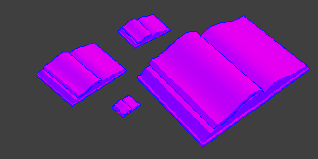
Create outline shaders for Unity that have a stable screen-space width, specified in pixels, regardless of distance from the camera.
Sobel edge detection you anyway will make in custom function code, in shadergraph you will just get depth/normal and put it at screen
Can you please show in shader graph if possible?
i mean, how do i put it at the screen (sorry if im asking way too basic things, im pretty new to shaders)
@amber saffron do you have any example to create depth custom shader?

But it's for URP fullscreen feature, time ago i maked it without fullscreen feature, just in render feature blit result

are you referring this for hairs?
Not, but in your case it's must works same
ill try, but thanks!
Hello, im back, i wanna ask that where did you get the sobel custom function?
Well, im strugling with using the sobel filter for unity's built-in pipeline. I really dont have anything, but im wondering how you can do it.
Most videos on youtube were using URP only, and some other only were explaining generally about the filter, and just showing it.
#ifndef SOBELOUTLINES_INCLUDED
#define SOBELOUTLINES_INCLUDED

// The sobel effect runs by sampling the texture around a point to see
// if there are any large changes. Each sample is multiplied by a convolution
// matrix weight for the x and y components seperately. Each value is then
// added together, and the final sobel value is the length of the resulting float2.
// Higher values mean the algorithm detected more of an edge

// These are points to sample relative to the starting point
static float2 sobelSamplePoints[9] = {
    float2(-1, 1), float2(0, 1), float2(1, 1),
    float2(-1, 0), float2(0, 0), float2(1, 0),
    float2(-1, -1), float2(0, -1), float2(1, -1),
};

// Weights for the x component
static float sobelXMatrix[9] = {
    1, 0, -1,
    2, 0, -2,
    1, 0, -1
};

// Weights for the y component
static float sobelYMatrix[9] = {
    1, 2, 1,
    0, 0, 0,
    -1, -2, -1
};

// This function runs the sobel algorithm over the depth texture
void DepthSobel_float(float2 UV, float Thickness, out float Out) {
    float2 sobel = 0;
    // We can unroll this loop to make it more efficient
    // The compiler is also smart enough to remove the i=4 iteration, which is always zero
    [unroll] for (int i = 0; i < 9; i++) {
        float depth = SHADERGRAPH_SAMPLE_SCENE_DEPTH(UV + sobelSamplePoints[i] * Thickness);
        sobel += depth * float2(sobelXMatrix[i], sobelYMatrix[i]);
    }
    // Get the final sobel value
    Out = length(sobel);
}

#endif```I found this
I did somethinglike this recently - learning you can read the depth map in a custom function node is so much better than the spider-graphs I have seen!
I wish I had seen this a week ago!
Oh nice! Youre using URP?
Yes URP - and things changed in 2022 LTS, I had to search for up to date info!
Oh ok, im trying to use it with built-in renderer so things are a little hard for me
ok there should be more examples for built-in, the pattern is similar to URP at the core, but can you even use shader graph?
Yeah, shader graph is avaible for built-in
Well you need to use a custom function node in the graph to do as above https://docs.unity3d.com/Packages/com.unity.shadergraph@14.0/manual/Custom-Function-Node.html
Hey do you get an error like this?

It is painful to learn, I got lots of errors. You need to put the function name in the node without the _float bit that you want to use
the _float bit is in the code to specify precision but should not be written in the node options when you write the function name
- set the node precision mode to float instead of "inherit"
ah ok
Also to be clear, the code posted above uses the name DepthSobel, not EdgeDetect which is the cause of the error
it almost always is float though when inherited - does anything put _half as default any more?

Any ideas why Scene Depth node works, but this code - not (just black)?


In URP settings, yes
I looked at scene depth node code and just copypaste into custom function, but for some reasons it's not work
When you use the Scene Depth node, shadergraph adds a #define REQUIRE_DEPTH_TEXTURE behind the scenes which actually enables the DeclareDepthTexture include and those macros/functions
are you using FullScreenPassRendererFeature and set requirements?
But Scene Depth node it's added, but don't connected to anything
In same shadergraph
If it's not connected the node is ignored, it won't change the compiled result
If you're using the code you posted above, make sure the inputs/outputs match the function used. float2 UV, float Thickness, out float Out
I'm trying to convert a fullscreen shader to a per-object shader. I've changed the type to Unlit, so the dependencies should change as well, right?
and in same order! it is easy to break!
Unity should provide an edge detect example as it was a lot to learn about what you can do in a custom function node and the setup for a FullScreenPassRendererFeature. Would be a great addition. Most examples are out of date with latest LTS
iirc fullscreen graphs always include the depth texture, but other types don't - and need a Scene Depth node
Not sure if there's a way around it in a custom function. You could try #define REQUIRE_DEPTH_TEXTURE but it probably needs to be before other includes so might not work
Easiest way would be to just use the scene depth node at least once
How are you making it per object? As in with Volumes and layers, or a typical material shader that will look at depth?
or a typical material shader that will look at depth
Make sure it's transparent too
Surface type?
Yes
That is the trouble with the shadergraph shaders - what you can do and how is difficult to understand. I had to search the package's (URP) shade code to find the functions to read from depth and normal buffers and then I found out I could not use SHADERGRAPH_SAMPLE_SCENE_COLOR for some reason
And it's have a lack of hotkeys, will be cool see something like node wrangler from blender
SHADERGRAPH_SAMPLE_SCENE_COLOR just comes out black for me for example unless I read from screen in the graph. Where as depth and normal are ok
you still can't have integer vertex attribs in shadergraph to this day
Is that in a fullscreen graph? The generated code automatically includes the depth and normal textures but iirc the opaque texture is only enabled when using Scene Color node.
But sampling _BlitTexture probably works
Well, that works
Yes that seems to be so - it is using FullScreenPassRendererFeature with everything enabled
Yes, i used _BlitTexture, works pretty well
I have troubles with normals btw, just black. What i can do with it?
ok - that is like what?! though. Like can't Unity provide some reference to these shader oddities! I only know for fullscreen
May be here same situtation, as with Depth? I just need some defines?
And how i can know, what node defines? In source files nothing as i see
Or may be not, because i can't get normal if i just use node
Is _BlitTexture a special-named texture input for your graph or you can use it as-is in a shader node?

color = strength * SAMPLE_TEXTURE2D(_BlitTexture, sampler_BlitTexture, UV);
For example i have that
There's probably a similar REQUIRE_NORMALS_TEXTURE define to make the macros work. But sampling _CameraNormalsTexture should work.
That said, you need a renderer feature to force URP to actually generate the normals tex (in forward/forward+ at least, not sure about deferred)
ah... _BlitTexture is not defined though
You can define it TEXTURE2D(_BlitTexture); outside the function (or probably as TEXTURE2D_X to properly support vr) - or maybe add it to the Blackboard
I think the fullscreen graph should already declare it though 🤔
I think you have to add it to the shadergraph and pass in. I am just doing normal scene color node read for now! If I needed further reads I will add to blackboard
well my material is blank and white but i guess its because of the hlsl is not compatible with built-in renderer

I know a game that did this amazingly even using the built-in shader: https://www.reddit.com/r/Unity3D/comments/taq2ou/improving_edge_detection_in_my_game_mars_first/

but i cant get a way or dont know the way to do this
Well, can i just use fullscreen feature? That will force to generate textures? Oh, sampling just works for me. Thanks
does anyone know how he did this?
sorry if im asking too straight questions but i dont really know where to start from ;-;
I would try
#ifndef SOBELOUTLINES_INCLUDED
#define SOBELOUTLINES_INCLUDED

// The sobel effect runs by sampling the texture around a point to see
// if there are any large changes. Each sample is multiplied by a convolution
// matrix weight for the x and y components seperately. Each value is then
// added together, and the final sobel value is the length of the resulting float2.
// Higher values mean the algorithm detected more of an edge

// These are points to sample relative to the starting point
static float2 sobelSamplePoints[9] = {
    float2(-1, 1), float2(0, 1), float2(1, 1),
    float2(-1, 0), float2(0, 0), float2(1, 0),
    float2(-1, -1), float2(0, -1), float2(1, -1),
};

// Weights for the x component
static float sobelXMatrix[9] = {
    1, 0, -1,
    2, 0, -2,
    1, 0, -1
};

// Weights for the y component
static float sobelYMatrix[9] = {
    1, 2, 1,
    0, 0, 0,
    -1, -2, -1
};

TEXTURE2D(_CameraDepthTexture);
SAMPLER(sampler_PointClamp);

// This function runs the sobel algorithm over the depth texture
void DepthSobel_float(float2 UV, float Thickness, out float Out) {
    float2 sobel = 0;
    // We can unroll this loop to make it more efficient
    // The compiler is also smart enough to remove the i=4 iteration, which is always zero
    [unroll] for (int i = 0; i < 9; i++) {
        float depth = SAMPLE_TEXTURE2D(_CameraDepthTexture, sampler_PointClamp, UV + sobelSamplePoints[i] * Thickness).x;
        sobel += depth * float2(sobelXMatrix[i], sobelYMatrix[i]);
    }
    // Get the final sobel value
    Out = length(sobel);
}

#endif
ooh how does he write the surface id in to a buffer - that is something I could use
Also make sure you are generating the depth texture. Built-in uses camera.depthTextureMode = DepthTextureMode.Depth; iirc
https://docs.unity3d.com/Manual/SL-CameraDepthTexture.html
Ah ok, thanks, i didnt know that
That's the kind of thing you'd do in a custom renderer feature. I've got an article which might help explain (mostly for 2022.2), but it's slightly outdated now. https://www.cyanilux.com/tutorials/custom-renderer-features/
Specifically the example section draws renderers into a custom target - and the override material would be responsible for writing the ids, probably via vertex colors.
ok thanks - that is really the way I need to do edge detection, but might have to allocate some time for that change!
But I already do a custom render for edges, just not to fill out ids first
How do you come up with surface ids like that?
i tried that but i still get a blank texture
That actually looks painful to implement. You have to write out a different value for each separate mesh section (generated on mesh import) to get the material ids in a texture. Sure is clean, but yeah could take a lot of effort to get working, would need to add vertex color values to mesh to use with a custom material... hmm I can't be hacking the meshes like that!
yeah, that guy is a genious 😂
I played his game, i recommend it
very fun game, generally i really like this art style and it suits like space enviroments
I will do a very bad idea but i will ask ai to littearly rewrite the hlsl file for me
These stuff are really complex, i didnt actually expect it to be hard to make edge detection shaders
Or its easy, i just cant find or dont know how to do it
how do i fix this problem with the material? like the stretching

It's UV unwrap problem posibly
Oh im getting somewhere slowly

the thing is that its just very weird
and when you get a little far away the outlines dont appear
What does this error even mean:
Property "..." already exists in the property sheet with a different type: 0
There should be a property name in the "...", I don't know if you just replaced that bit. But looks like this can happen if there's a mismatch between the property type as defined in the Properties scope in ShaderLab, and the uniform in the HLSL.
I cut out the property name from the message because it's too long
I used Int in shaderlab and int in hlsl
Int is a legacy type, which is actually a float, because ShaderLab used to not support real integers. Integer is the real integer property type.
I once tried using Integer and it didn't work
neither with int nor with float in hlsl
I'm gonna check it out again, because I understood what my real problem was for now
I scaled a concave object, had camera inside it and cull to BACK, so I had no ide why it wasn't rendering 🤦♂️
is it possible to set an attribute inside a shader graph? for example, right now I have a Gradient Noise node that offsets with time and I need to be able to access it in code. this means I have to have a Texture2D attribute that I need to set to the gradient noise. is this possible to do?
@tidal forge in the URP asset you can force depth prepass so both the depth and normal textures required for the outline effect happen before opaques. Then have the fullscreen outline pass's RenderPassEvent be BeforeRenderingOpaques and have it render to a rendertexture, then assign that rendertexture to a global shader variable via cmd.SetGlobalTexture.
This way you can have your individual opaque objects' shader sample the outline rendertexture and blend the outline pixel color with the object's pixel color along with any individual per-material adjustment to the object outline you want.
The caveat though is it would require your outline algorithm using depth/normal maps to be adjusted to only render outlines on the inner edge and never the outer, because the individual object's shader won't sample the outline pixels if it's on the outer edge. I can't tell if the outline algorithm you're using is outlining the outer or inner edges. Is it public? I'm curious how you do yours.
for some reason when i deleted my render texture my screen went bright white and i dont know how to fix

@timid sky on the camera in the inspector try clearing the target texture. it says Missing (render texture) because you just deleted it. it should be None. If that doesn't work try hitting play. sometimes unity view doesn't refresh
didnt work and i hit play
is that your only camera
no i got a second cam for the weapon
sorry then i don't know. i think it's a minor issue but it's hard to tell without having it in front of me
what was it
idk
If I'm making a game involving a submarine, and the game takes place in an ocean completely covered in ice, does it make sense to use a water system like Crest or Unity's HDRP water system, if I don't need waves? I just need a shader for the underwater visuals and I need to be able to incorporate physics like buoyancy.
No. You can make your own underwater effect and physics.
Thanks! Any suggestions on how to make my own underwater shader that supports volumetric lighting?
No clue. A full screen effect/postprocessing effect probably. You'll need to research it.
ive gone thru every shader and mesh adn swear theres nothing with that shader
im making my avi quest compatable and everything else is fie... besdies this one error

can someone help with this?
I currently have a script to procedurally generate a mesh, which involves a large number of UVs to obtain a flat shading effect. I'd like to improve performance. Will switching to a "normal" mesh and using flat shading shaders be more optimized?
Are you using particle systems in the prefab?
Probably. You're comparing two separate things. Your procedural generation is probably CPU bound, while a shader would affect the GPU time.
[ExecuteInEditMode, ImageEffectAllowedInSceneView]
public class ComputeShaderTest : MonoBehaviour
{
    [SerializeField] Shader shader;
    [SerializeField] bool renderInSceneView;
    Material mat;

    private void OnRenderImage(RenderTexture src, RenderTexture dest) {
        if(Camera.current.name != "SceneCamera" || renderInSceneView) {
            mat = new Material(shader);
            Graphics.Blit(null, dest, mat);
        } else {
            Graphics.Blit(src, dest);
        }
    }
}
Any idea why this shader isn't rendering in the scene view?


OnRenderImage isn't running in scene view to begin with and I have no idea why
(I'm using the built in render pipeline)
Thanks, that's what i tought
Yo! Has anybody used this shader in a mobile environment? I am having difficulties with some of the shader parameters in my apks, they work fine in the editor. The issue is only on sprites that are loaded from a sprite atlas. Here's a link to the shader: https://assetstore.unity.com/packages/vfx/shaders/all-in-1-sprite-shader-156513

Add depth to your next project with All In 1 Sprite Shader from Seaside Studios. Find this & more VFX Shaders on the Unity Asset Store.
it's a paid asset, you should ask the asset maker/seller
Why can't I select the Red


Hello
Can u helpme?
You cant select it?
Try disconnecting all the nodes from it then change, maybe that works
if that doesnt work then turn on the graph again
it's a float node, selecting everything will automatically select red, I think...
How can I select red? In the tutorial video I watched, red is selected.

I am about to lose my mind. :'8
As rakyat mentions, since the input is a Float, there is only one, red component. So Red=Everything. It doesn't really make sense to use it just on a Float really, you'd use Channel Mask on a vector type, what are you actually trying to do?
OMG cyan 😄

Isn't this your system?

Створення ефекту сканування місцевості в Shader Graph та Amplify на Universal Render Pipeline в Unity. Unity Shader Graph tutorial.
Blit script: https://cyangamedev.wordpress.com/2020/06/22/urp-post-processing/
Screen position to World position: https://forum.unity.com/threads/computing-world-position-from-depth.760421/
Більше корисної інформац...
Maybe an earlier version. The node isn't doing anything here though just ignore it
I don't know what I'm doing wrong, but I'm using almost the same version as the person in the tutorial video.
I have no idea why everything is white. In the video, it's not white for the person demonstrating.

Check the name (and reference) of the texture property, you're using "ManText" but should probably be "MainTex" (with reference _MainTex), or _BlitTexture in newer versions (blitter API)
I should use the newer version then, as I'm using the blit version that the person in the video used.

In the include file the function is named LightingCelShaded_float, so shadergraph is expecting "LightingCelShaded" as the custom function name, while you seem to be using "LightingCelShadedNode".
Also unsure if some of the functions used will work in Built-in target, I'v e only use custom lighting stuff in URP
Okay, I'd like to ask one last question, and let me also mention it's quite surprising to come across the owner of the system
. Now, should my MainTex texture name match the texture name in your script?

No, as long as the reference field of the property is _MainTex it should work
Is there any other setting I need to adjust?

Normally, I've been using Unity for years, but since I've never looked into the shader side, I'm so unfamiliar with it that I can't even describe how much difficulty I'm experiencing.
I would check what the scene looks like without the blit enabled. If it's still magenta, you may not have converted built-in materials to URP
See https://docs.unity3d.com/Packages/com.unity.render-pipelines.universal@17.0/manual/InstallURPIntoAProject.html
Oh ok, thanks. Sorry for being late 😅
Yea i checked and it sadly uses some URP stuff

Also if you happen to be using Unity 2022.2+, URP now includes a Fullscreen Pass Renderer Feature which could replace the blit one.
And a Fullscreen Graph type that goes with it which could simplfy the graph - can replace the "Screen to World Position" group just with a Position node (set to world space) as that graph type does the depth reconstruction for you.
And use URP Sample Buffer node set to "Blit Source" instead of Sample Texture 2D, and remove the MainTex property.
Hey! In the video I show the shader graph I'm using. Which I've also just posted screenshots
It uses the CalculateDepthDifference graph to get a difference I plug into my foam shader logic. The foam is the white texture on my water meshes. I want it to mostly show up around objects that are in my water mesh.
But my problem is, even when an object isn't touching my water, because of the depth, foam is still rendered. At the end of the video, you see me moving around a cannonball in the game view, and you can see a white foam trailing behind it in the water. I don't want that to happen. Because the cannonball isn't even touching the water.
How could I do this?
Sadly this isn't my shadergraph. I want to learn shaders and how to use them but they just feel like a massive feat and with the how much I'm learnin when it comes to just coding in Unity alone, I can't learn shader graphs rn XD


It's a bit weird that your depth texture seems to be a frame behind. Maybe try adjusting the Depth Texture Mode setting on the Universal Renderer asset?
My friend, you're truly awesome... but right now, for some reason, it's only updating in the editor screen, I can't see it in the game screen 😄
I'd make sure this is enabled

I don't think the problem is ending anytime soon; this shader seems to be devouring me. Now, for some reason, it's only happening when the game screen comes up with the mouse.
Hmm, not too sure why that is happening
Would that just be "Depth of Field" Because that's all I see in the settings. I'm using URP
At least that's the only setting relative to Depth I see

It's not in project settings but is on an asset somewhere in your assets. Usually under Settings folder if using the template
I guess you can also get to it via the Project Settings -> Graphics. Double click the Scriptable Render Pipeline asset assigned at the top, then the Renderer on the list at the top of that
Ahhh thank you. It was set to "After Transparents"
Omg that fixed it. My 4 day issue is over
I love you ❤️
Since you're using 2022.3, I'd try these changes - #archived-shaders message
Can someone please check #archived-urp :>
I've already done it, everything works, my outline is internal, so I had no doubt that everything would work.
I repeated this implementation:
https://github.com/KodyJKing/three.js/blob/outlined-pixel-example/examples/jsm/postprocessing/RenderPixelatedPass.js


GitHub
JavaScript 3D Library. Contribute to KodyJKing/three.js development by creating an account on GitHub.
And now i with new problem.
How i can get random point at mesh and get world pos and normal from this object at this point?
I can imagine how to get a random point, but with world position and normals - no idea
I did it!
Hey so I have some nodes here that operates as a angle circle mask from the UV center.

I want the masking to start from the center right and rotate around the circle (like you're working your way around the unit circle)
Right now it expands from the center right in both direcions.
If you want to keep using this set up, I'd just figure out the amount you need to rotate the whole thing to achieve what you want (sounds easy enough math to do) and rotate the incoming uv coordinates by that amount, the Rotate node should help with that
What I need is a mask that swings around in an arc. I'm fine with changing what I have to achieve that.
I know it's probably some atan something or other.
Rotate the B vector of the Dot product node
Any tips here?

trying to get a circular gradient around the UV center
Try this :

And change the rotation value of the rotate node
I imagine that would work, but is there a solution here with arctangent? Like any way to generate a circular gradient with pure math?
This ?

(it is "pure math" under the hood)
Or maybe you got confused because the gradient seems to be "cut" in our both cases ? That's just because the values are out of the (0-1) range, and can't be displayed in previews


Damn thanks. I think it was the addition of the 0.5 I was missing to pump it up.
Hmm. Any easy way to have it expand from the center left and then around counter clockwise?
I could use the rotate node I guess.
anybody?
This ?

This. Like it's progressing through the unit circle

Shouldn't the first argument of Blit be src ? doc
Or maybe you don't care in your material 😅
nobody else uses it, and it wouldn't matter if my shader didn't rely on my scene
but now that you mention it, that does seem pretty counterintuitive 🤔
but my issue still remains that OnRenderImage won't play in the Scene 😭
Like this ?

OnRenderImage doesn't work in URP
oh nevermind then
HDRP too?
Nope, as stated in the doc
Not sure if related, did you try to enable the image effect here ?

Behaviour needs to be like this, so I'm using that gradient.
Ok, so you want to do a circle mask on it ?
interestingly enough, my Camera.current is Null in scene view when printing from Update
let me see
THAT WAS IT
TYSM!!!
ily remy
can't believe that was it
some other guy I was watching do it doesn't have that on either
Yep. The idea was to produce a circle mask with atan, and an input where 0 shows nothing, we progress counter clockwise from the center left position, and an input of 1 is a full circle.
Got it, I'm doodling the graph to show you
This is my current graph. I just dont like the rotation node.


Oh missed a thing, add a "one minus" node before the top smoothstep to do it counter clockwise
@steel notch note that with the polar coordinates node, it makes the graph even tighter :

Thanks for the help.
How did you end up separating the depth edge pixels from the normal edge pixels for the highlight/shadow outlines? Or is it all 1 outline and you're changing the outline color using main light direction?
Seperated strength for normal and depth pixels
oh depth in red channel and normal in green channel?
i wonder why the threejs guy didn't do that
Normal uses rgb or not?
Oh, outline
Well
float strength = depthDiff == 0 ? 0 : (depthEdge > 0.0 ? (depthEdgeStrength * depthEdge) : (normalEdgeStrength * normalEdge));
Color = color * strength;
I use this like that
color is color that i achieved by shading
Or in fullscreen just blit tex
@tidal forge oh, then how are you achieving the highlight edge? if color * strength can't ever be greater than color since strength is clamped to 0-1?

oh the normalEdgeStrength property is > 1
in my case strength just not clamped to 0-1 and less then 0 it's dark outline, more then light and 0 it's just nothing
You can see demo btw
oh (1.0 + normalEdgeStrength * nei) that explains it
Well, i have some troubles, when trying achive best looking outline. That double-outline looks awfull... How i can remove this?

I can share project, if someone interested
@tidal forge have you seen this guy's outlines? https://www.youtube.com/watch?v=LRDpEnpWohM he shows the code in the video. I think it's also a custom variation of the threejs outlines. It might solve the overlapping outline issue.
Yep, i seen, but this not works for some reason
Forgot about this vid, btw
@tidal forge also what camera far plane do you use? I've found that the edges degrade unless the camera far plane is within a pretty specific range
is there a way to keep unity's built in reflection when applying a shader? I want to apply a custom color shader for a rock model I made, however it looks really weird without unity's built in reflection. the first image is before the shader was applied and the second one is after it was applied.


Well, that just means that your shader calculates lighting in a different way than the unity shader. Did you write that shader or made it in shader graph? Can you share the code/graph?
just a simple lerp between colors

is it just a setting i need to change or do I need do add more nodes?
Can you take a screenshot of the graph settings?

Changing the material property to lit is probably gonna bring back the unity lighting.
yep, that does it. thanks! I was thinking that this could be it, but a few hours ago when I tried this some of the textures started warping through each other. now that doesn't happen anymore i guess. thanks for the help!
is there a way i could traverse around this circle and distort it according to some pattern to try and strecth it like how i drew with the red line

Why am i getting low fps with just nothing? I tried to disable the outline shader but its still the same

I think you can use polar coordinates + some noise(perlin?) to do it.
It looks like a CPU bottleneck, so probably unrelated to your outline. Use the profiler to investigate it.
(notice that the CPU main thread takes 22ms/frame, while the rendering only takes 2.9ms/frame)
Can't see anything like that
@astral finch, i think author just doing something like that, where it's not full outline, but good enought. Hes hase depthDiff < 0 in strength calculations, that cuts off a decent portion of the outline but also fixes the double outline problem

He also doesn't show good examples to prove that this isn't the case.
Well i fixed that lol

Not in good way, but it's possible
Basically I just took the abs depthDiff for cases where the outline is normal. If you just take the abs depth difference, but the depth is drawn boldly, in 2 pixels, duplicating itself
Like that

I followed a simple tutorial to make a basic procedural skybox but i go an issue along the x axis. Any idea how i can fix this ?


The stars get stretched because the default Voronoi is 2D; you could get a 3D Voronoi node (online), or do some stuff with ddx and ddy nodes to rescale the stars
Probably things would be a bit more even if you Swizzled after the Normalize to get the xz component
(that way the stretching is on the horizon rather than halfway across the sky)
thx
I have a camera pointed at a screen/video, and use a Rendertexture to display said view on a seperate object. How can i make it so the rendertexture turns the footage into a "cutout" of sorts, so only a certain color is turned invisible, making the 2nd image a cutout of what the camera is seeing.


It will be simpler to use a transparent image as the texture with a transparent material
In my use case, the image displayed will be a video stream, so i cannot turn that transparent as far as i know.
Some video formats can be transparent, or you could have another video for the alpha channel
There's also a Replace Color node that can do what you ask in a shader
I would scrutinize if an animated character really needs a video and a render target camera, rather than animating it in-engine or using a flipbook image sequence
how would i use the alpha channel method? is there a material that can do that? (or does poiyomi contain such feature, as i already have that installed)
I'm not sure which method you mean specifically but all I mentioned would have you make a shader that samples a texture for the alpha, and optionally modifies it some way
I don't know of any that specifically does it that way out of the box but Shader Graph is relatively easy to learn
Hm... allright ill try that. Thanks for the idea! I'll ask again if i have any questions if that's okay?
You can ask here yes
I'm also still curious why your character must be in video format
I see it often done when there are more suitable methods out there
I actually managed to get the alpha-map idea to work! Great! Now i just have to sample the background from the feed and it should work! Many thanks for the idea ^^

It's a bit weird of an idea i had :P
but i can elaborate once it's actually working ^^
You could elaborate even before that, as we may be able to guide you
odd idea, ik, but i got curious to see if it works sooo :P
I want to offset z on verticies in perspective HClip space so that the pixels don't change but the zsorting does. I've got it mostly working, but the offset seems to be changing based on camera distance. I think I'm maybe missing a transformation of my offset from worldspace or viewspace to HClip space, however my attempts to introduce it have all failed to produce a desireable result.
What is your camera setup? Orthographic rotated 30 degrees down? Some of my outlines start disappearing if the camera far plane is greater than ~200, and or less than 125. I'm guessing because it affects the quality of the depth and normals textures and thus the edge sensitivity

Well, i think that can be problem if you use depthnormal texture and not seperated ones
i use the dedicated depth texture for depth and the depthnormals texture for normals
https://youtu.be/fW-5srSHDMc?si=d0ml-oM1fEmsm_Ib
Here something about that
✔️ Works in 2020.1 ➕ 2020.2 ➕ 2020.3 🩹 Fixes
► At line 39 in EdgeDetectionOutlinesInclude.hlsl, the sixth entry in sobelSamplePoints should be float2(1, 0), not float2(1, 1)
For 2020.2:
► When you create a shader graph, set the material setting to "Unlit"
► The gear menu on Custom Function nodes is now in the graph inspector
► Editing properties...
what textures are you using if you're not using the unity depth and depthnormals textures
are you making a custom depth texture?
I am using strandart depth and normal (not depthnormal) textures
Oh _CameraNormalsTexture I believe is the same thing as the depthnormals texture
maybe it's the scale of the objects i'm using. how big are your objects? Maybe 1 unity unit isn't large enough making the depth differences quite small relative to camera size and distance
Big enought, like normal size
what are your camera settings

The problem in depthnormal, in video that i sended some techniques for getting rid of problems
that video talks about non-linear depth adjustments. that's with a perspective camera. orthographic cameras already use linear depth

How do you get the pixelated look? It's important that the depth and normal are pixelated too
i render the main camera to a 640x360 render texture
Show a screenshot of the problems
i'll make a video one sec
streamable seems to downres uploads now which sucks but you can still see it.
I scaled up my model to match your orthographic size and far plane.
I overlayed the outline fullscreen pass to show the outlines changing as I scroll camera far plane back and forth from 150 to 1000 https://streamable.com/8z86z4
my outlines separate out the concave and convex and outline edges into the three color channels, but it's still essentially the same way the threejs and that one youtube video does it
Btw where did you take this scene?
i made it in blender, trying to build that one tessel8r scene
Something wrong with edge detection
it happens to me even if i use the raw threejs method or the one in that video instead of this custom variation
so what else could it be
For me outline stable and doesn't depends at cliping planes at all
it must break at some point, what's the lowest you can set far plane to before objects start disappearing
It's just how clipping works, but even at clipping outline works as you see

they're really rock solid. that's so strange
and you're doing a fullscreen renderer feature pass for the outlines?
No, I recently switched to per-material, but it worked just as well with fullscreen
maybe it's only happening because my shapes are more complex and i should try simple shapes
Lenins statue don't complex enought?
good point
guys can i ask about one problem?
@tidal forge how different is your outline shader from this? https://hatebin.com/kbvwuwoprp
i dont know its related to shaders or not but everything is pink
so we basically have the exact same outline shader, so it can't be that. you're saying this doesn't happen to you? i must be not doing something important

@tidal forge sorry i'll stop bothering you but 1 last question. can you add this crate model to your scene at scale = 3 and show me how it looks for you?
Did you recently add HDRP or URP to your project?
sorry could you elaborate, im not very good with uvs but trying to get better
Well, it's a lot to elaborate. Maybe watch this video first to grasp the concept:
https://www.youtube.com/watch?v=ZI1dmHv3MeM&ab_channel=TheCodingTrain
Ok thanks
so I understood what you meant with the noise and the polar, but Im still a bit confused on how you actually iterate radially via shader graph. I get it for code
Well, how are you drawing that circle now?
rn im either using the ellipse node or polar coordiante uvs with a rectange node
Can you take a screenshot?

Yeah, I guess it's not that easy to apply the same stuff in a shader graph, but here's an example of how you could do it

oh wow thanks so much, i didnt even think about adding to the uvs. Let me see what I can do from here.
Here's another way. I think it's closer to how they did it in the video that I shared earlier.

so is each pixel of the uv node a vector 4?
i like this way better; correct me if im wrong, but increasingh the scale of the gradient will lead to more drastic distortion and changing the multiply factor increases how much effect each distortion has?
Technically, it's a vector2 I think. Or rather float2 if we're talking about how it looks in code.
Yes, that's correct
thanks, I wonder whats with the color representation then
Wdym? The red, green, yellow in the uv node?
right it's scale 3

no
im redownloaded again and again(32bit version and yes i know it doesnt show 32bit versions on archive anymore)
im using unity editor 5.6.7 (that version with everything pink)
but before to switch to 5.6.7, that doesnt happened in 4.6.3 version
(absolutely everything is pink expect material from assets)
Why this can happen? Grass it's billboards so rotated to camera
Looks like a rendering order issue. If the big grass plane and the landscape grass are both transparent objects, it seems that at some angles the big plane is considered further aways from the camera than the landscape grass, and is drawn before
Is there a reason you are on such an old version of unity?
That was released in 2019
when you inserting asset:

hey people, i am trying to convert a blender shader into unity what is the equivelant of this in untiy shader graph?

Show the inspector for one of the materials that are pink
What render pipeline are you on? Builtin, URP, HDRP?
URP
Alright, I know that HDRP lit shaders have a Metallic and Roughness (or smoothness) output, not sure about URP
the default is pink-for example when you creating cube:hes pink

im tried legacy shaders
(random texture for example)

Read the forum post I linked. It is related to the error show in the bottom of your screenshot
Best thing you can do is try the fixes suggested there, and also look for similiar issues online.
Since you are on such an old version, I dont think anyone here knows how to help
And search for the other errors in your console too
im somehow did fixed it by just selecting shadow cascades

or not?
anyways if it will appear again... i will get solutions from link
This is basically the shadergraph output when you are creating a "Lit" shadergraph
Unity uses smoothness instead of roughness though, but smoothness = 1 - roughness 🙂
yes sure but the shader I am trying to convert of is a mixed shader (a cobblestone) and i need to mix those 2 shaders together
I am trying a different appraoach now .. I am tyrying to bake the blender shader into a texture instead
In scene view window, on the Gizmos menu, try deselecting "Selection outline". This worked for me
where is the gizmos menu?
nvm i was stupid
@civic lantern it doesnt works like shader model 2 and selection outline disabling