#archived-shaders
1 messages · Page 74 of 1
That being said, it's a pain in the ass to get the ide working with shaders, so maybe just ignore it.
As long as it compiles in unity, there's no problem.
well shoot, I'll let you know if I ever find a way
I told you the way. You just need to include the correct files.
You can find the unity shaders source code on GitHub, it's in open access. Import it into your project and provide and #include directive in your shader with a correct path to the correct file.
alright, thanks!
Though I wonder if it's gonna make unity complain if you put it in the project
well I found the hlsl file and included it, which resolved the type error in the parameters, but now SAMPLE_TEXTURE2D is not declared https://github.com/Unity-Technologies/Graphics/blob/master/Packages/com.unity.render-pipelines.core/ShaderLibrary/Texture.hlsl

GitHub
Unity Graphics - Including Scriptable Render Pipeline - Unity-Technologies/Graphics
I'm guessing it's in another file but I'm having trouble finding it
Yep. It's defined somewhere else. That's why I said that you better forget about intellisense with shaders.
Maybe in Core.hlsl
thank you this is an option I can look into
does anyone know of anything like this this that actually works in URP?
(cheap shader based DOF)

Add depth to your project with Fast Depth of Field ( Mobile , URP , VR , AR , LWRP, Default Pipeline ) asset from Rufat's ShaderLab. Find this & more VFX options on the Unity Asset Store.
Is it possible for two materials on a gameobject not collide with one another.

The element 0 is the top material and when the dissolve is done, the "Element 1" is th cloaking shader.
It turns out like this.
Assuming you don't have submeshes(or rather only have 1 submesh), then the mesh is rendered twice, for each of the materials. Neither of the materials k ow about the other so the latter one just draws on top.
Anyone know how to make a projector that makes a material's smoothness go up? I'm kinda struggling here
projector? you mean something like decal?
I'm making a fullscreen shader that turns everything grayscale except the color red (I want to control the color that doesn't get filtered but only red should be fine for now. I found something to make everything grayscale but I don't know how to bring back the red. does anyone know?

close enough, you can modified it further tho https://gamedevbill.com/hsv-shader-graph/


How to set up Hue Saturation Value, or HSV, Shader Graph nodes. Using Unity's Shader Graph to convert translate from RGB to HSV and back.

Full screen shaders in Unity's HDRP, URP, and Built In Renderer. How to create custom post processing effects in all of Unity's renderers
thanks
Yeah. Is that doable in Built-in?
i am not quite sure about BIRP since i never touch that but in URP you can use this in shadergraph

Hey guys how are you ? I have a question a don't know why my shader light is bug can you gelp me ?
Hello, I am trying to apply a texture to my procedural generated worlds and I am having trouble. I would like to paint the top of the world green and the bottom gray. In the transition from green to gray I would like to create a line of a darker green.
In the 1st pic I was trying to check where the color is 50% green and %50 gray and paint it a darker green, but since it does the coloring per triangle instead of per pixel, if you zoom in it looks weird.
In the 2nd pic I tried to solve it by lerping from green to dark green, and from dark green to gray depending on the normal, but i get a dark green-gray for the rocks.
How could I do so I get a distinct dark-green line with a certain width from where it goes from green to gray?


Can you not just add two conditions, so if it's in between the two thresholds it's dark green?
Oh actually I see what you mean
Yes, it is what I did in the first picture, and it does the painting per triangle
I think if you're doing flat shading, then it will be per triangle if you're working based on the normals
You could create a smooth-shaded mesh, then calculate the flat shaded normals and use the smooth shaded ones for colouring
THe problem is i am creating all the mesh at runtime and unity doesnt have any tool as far as i know to create smooth shaded meshes. When i provide the mesh and tell it to calculate the normals, it just does it flat.
That happens when you're duplicating the vertices
If the vertices are all unique, then it would be smooth shaded
This is my code to create the mesh from the triangles generated with marching cubes: https://pastebin.com/Ege4uz5Q
Do you know a way I could avoid adding duplicated vertices without checking all the vertices written till now and making it O(n^2)?
Pastebin
Pastebin.com is the number one paste tool since 2002. Pastebin is a website where you can store text online for a set period of time.
A hash map would be O(N)
You mean O(1)?
the lookup is O(1)-ish, so doing it N times is O(N)
since it's used in a loop
how can i add fog to my sprite unlit shader ? ive tried it like this but it doesnt work

I'm noticing an error in my development build:
<i>OSXPlayer "fens-mbp-2.lan"</i> Material 'Waveform(Clone)' with Shader 'Unlit/Waveform' doesn't have a texture property '_MainTex'
I do not need any textures for this shader.
Does Unity just try to cram one into it anyway? I guess I can add a property..
I don't attempt to set the _MainTex property; I'm only setting four properties that all do exist
ooh, I'm using it on an Image
and I bet it's trying to set _MainTex
If it's applied to a SpriteRenderer or UI Image then yes it tries to set that property
whoops, and that, itself, had a broken reference

I don't see any completely generic graphic component that doesn't even try to set a texture
so I guess I'll just give it a _MainTex property
good job fen

i am very bad at adding properties to shaderlab code on the first try 😭
I mostly use shadergraph, but if I do code manually I tend to just copy the property declaration from the docs 😅
The texture one has that extra {} too which I know others sometimes forget
I'm unsure of your desired result. That said, once you've created the mesh, you'll know the mesh's extents. Passing that info into the shader for each draw call MAY allow you to achieve what you desire in terms of color gradient per-object. You'll probably want to pass the info to the frag stage via an interpolator so you can work in object space.
I wanted to smooth the mesh and the guy who mentioned that i had duplicated vertices was right. Unity smooths lighting and coloring if vertices arent duplicated, if they are each one is colored and lighted independently giving that low-polyish style. I just modified the code that builds the mesh to delete the duplicated ones and worked fine, plus fixed a bug where if i was generating chunks with very different frequency in the noise, it would crash all the meshes and draw them incorrectly.
Hey so I've got a performance related question. In this image I have about 500 goobers. The entities are constructed from ~10ish different sprites all in a sorting group. Some of the sprites are lit (mostly the body) and others are unlit (the screen). The framerate is unfortunately pretty terrible. The profiler is telling me this is mostly a rendering issue, and the Frame Debugger is saying that I'm making about 2500 draw calls for transparent objects.

That's a lot of draw calls I'm pretty sure.
Realistically I don't expect to have 500 entities, more than likely about 200 as a max.
But I want to use this sprite shader for many props.
And I think it had broken batching.
How do I... unfuck the batching?
how do i split the scaling to x and y
Cant you maybe combine the screen and body into one material? Like, the unlit is mapped into emission channel. That alone should at least cut 500 draw calls... then, if you make the lit shader receive shadow, maybe you can make it not receive shadow...
Maybe? Really I'd like to know what is breaking batching, and how to fix it.
If I make all the materials unlit, then the draw call number goes way down.
Alright maybe I'm wrong.
Is it URP or Built In?
In Built in, additional forward pass (more than one light in one texel) may break batching, you can try adding noforwardadd to your shader (or just try the mobile shader family)
I'm not sure with URP though
URP unfortunately.
URP forces everything into one batch... not sure why batching breaks 🤔
Do the goobers change their scale (has different scale)? Iirc, that could also break dynamic batching
No they're the same size. They're all transparent sprites.
I thought it was maybe my custom lighting script, but I set them all back to the default sprite renderer and it's still behaving like this.
Like here is 1000 of them.

Animators off.
It's effectively just a collection of sprites.
13 frames, built.
Default sprite shader, 1000 units. 60 frames, built >_>

Only ~22 draw calls?
Bro what is going on.
Btw it seems that srp batcher only support sprite renderer on 2023.1 and later.
https://forum.unity.com/threads/srp-batcher-spriterenderer.1441009/

Unity Forum
The last time I tried migrating a project from the built-in render pipeline to URP about 6 months ago, I noticed that SpriteRenderers were contributing...
Well, I'm using sprite renderers and these 1000 sprites are all being drawn in ~22 draw calls.
It's definitely rendering many at once.
And this is over 4000 draw calls.

Did you use the profiler?
Used the frame debugger.
Use the profiler first to see what the bottleneck is
It's definitely rendering last time I checked
rendering is a complex system with many layers. Saying that it's rendering doesn't tell anything
Alright fair enough. 1 sec.

Would need to expand it quite a bit more


Hmmm... I think transparent materials are really contributing to the issue. Did you try making them opaque or cutout just for testing purposes?
I think it's also an issue that every draw call it sets up a rendering pass? This shouldn't happen with one shader normally.🤔

Can you share your shader?
Sure 1 sec.
Also, does the frame debugger tell you why the draw calls are not batched?
Problem is that we're pretty sprite based, as you can see. We construct sprites from many sub-sprites, so opaque isn't really an option. I am using alpha cutout as well for the transparent shader to try to save some speed.
In your screenshots I don't see anything that should be transparent. Cutout should do the job
These units don't. We have others that have a semi-transparent bulb on their head.
Also all the sprite sorting features break when the sprite is opaque.
Are you suggesting I separate the components slightly on the z?
Yet, the profiler data is for these sprites? And it clearly says that they're transparent.
I'm worried about parts improperly sorting in that case.
That's one option, but it's better to do sorting layers and order in layer
If anything, transparent is harder to sort that opaque
So I don't really understand the concern
I'm sorry I think I'm confused.
If I set the shader to opaque.
Order in layer doesn't work. Sorting layers don't work. Sorting Groups do not work.
Are you using the Sprite renderer?
yes
Then it should work.
Perhaps there's something wrong with your shader if it doesnt.
try a standard shader with the sprite renderer. Sorting order should definitely work. Otherwise there wouldn't be a need in it.
Yeah, it should work in urp the same way
Here is an opaque graph.

I have 2 circles at equivalent Z positions.
They are Z fighting.
they are in a sorting group

Are they on the same sorting layer and have the same order?
Green and yellow are transparent.

They sort correctly, and if you dont touch their sorting layer or order, they sort by order in the hierarchy.

Different order, different sorting.
take a screenshot of the red and blue circle inspectors


So they have the same sorting settings. Obviously they're gonna z fight
decide which one should be above and bump it's order in layer
Both circles have 0 in this picture.

that's the problem
Behold, the blue with a value of 1.

and red is 0?
mhm

Hmm... Then I'd assume that your shader does not respect these settings
Use the standard shader and see if it works
Also, it seems like you're not using a 2d Renderer in your urp settings
Nope. We're doing a combo of 2D sprites in a 3D world.
🤷♂️

I'm pretty sure the entire Unity sprite sorting feature set is dependent on transparent materials.
I'm pretty sure it's not. There's no reason for it to depend on it.
Well, then surely I'm missing something?
Take a screenshot of your camera inspector

Does anything change if you change it to orthographic?
No. Rotating the camera still shows Z fighting.
No no like the camera does settle on someone winning out.

Yes, so that's the correct behavior
but if I rotate just a bit...

That's the issue. You're not expected to rotate it
You need to decide which workflow is gonna be the main one: 2d or 3d
I'm rotating the camera, not the sprite.
if it's the former, then the sprites need to stay orthogonal to the camera.
Yes, that's what I said
...but why?
If it's 3d, you can't rely on the sorting settings for sorting
Because that's how the rendering system works. In 3d it sorts by position
In 2d layers and order take precedence
Okay but if the sprite is opaque it's writing to the depth buffer, no? We know the depth of the frag.
Can we not just go "this is a higher priority"?
That's part of 3d rendering, yes
You can. By moving them relative to the camera
I mean if I slap these on quads instead, surely I'll get the same issue.
wdym?
Sprite renderes are basically quads. With some extra features
You can use them both for 2d and 3d, but the ordering would change depending on your camera settings and orientation.
Give me a sec.
Here are the goobers moving around as transparent objects. Notice the camera is not rotating relative to the sprites.
Here's what happens if their shader is set to opaque.
Then the sorting order should work with opaque material
Are they orthogonal to the camera?
But it's not. The goobers ARE sorting correctly within their sorting group.
They are not. I guess I'll rotate them back 45 degrees.
Make them orthogonal
and make sure their parts have proper ordering within the group
Goobers are now orthogoal, ignore the big guy.
Eyes are gone, and their arms and legs still flicker (bit hard to make out).
looks correct to me
I don't see arms and legs at all.
As for the eyes, share their settings.
The eyes are on top of the screen sprite, which is a different material.
Is it an opaque material?
It is now.
Is the sprite orthogonal to the camera? Does it have a correct sorting order?
I have a simple test scene with a few objects and a directional light. If an item isn't too close to the ground or the directional light is fairly parallel with the ground then the shadows look good. If an item is close to the ground or the directional light is fairly vertical then the shadows look very bad. So, it seems that as the length of the projection increases the quality improves. Can anyone explain what's actually happening? Also, what can be done to remedy the issue? I've played around with a number of the shadow settings but thus far haven't found one to mitigate the issue.

Yes they're orthogonal. The sprite is rotated backwards 45 degrees, and the camera is rotated down 45 degrees.
I guess if I manually define values for each sprites sort order, it probably would work.
Ok so it looks correct now?
I really doubt that. Even if they do, it's probably just an undocumented behavior that you shouldn't rely on.
The only thing that relies on hierarchy order is UI.
I'm not crazy I swear.
Alright I appreciate the deep dive here but this isn't... optimal really.
No camera rotation? Ever? Not going to happen.
So either A) I work with transparency.
Or B) I somehow build these creates in a way where they become some type of opaque mesh?
And all their animations are built in?
And forgo the Unity sprite system.
Plus rotating the sprites back is going to be terrible for sorting with 3D objects behind them.
You would just need to make sure your sprites are orthogonal to the camera.
Or B) I somehow build these creates in a way where they become some type of opaque mesh?
Is this a viable option?
Not quite sure what you mean by that or why you would need that
Meshes can't be opaque or transparent. They're just an array of vertices and triangles
A lot of these types of 2D sprite/3D world games I see forgo using transparent sprites. They usually have just 1 quad displaying the whole sprite. (Also a lot of them tend to be pixel art).
Plus alpha cutoff.
There're only 2 explanations:
- They're following the rules that unity renderer defines, like you did now.
- They have a custom renderer with their own sorting logic.
Wait roll it back. Why are we even trying to make these opaque again?
Batching?
Overdraw?
Yeah, batching, performance, overdraw. All those things. It's probably only one of the issues though.
I'll be honest I've sort of been bouncing between Opaque and Transparent for the 2D creatures for a while. Interacting with a proper 3D world as a 2D transparent object... interacting with other 2D transparent objects can be incredibly messy.
But these sorting issues with Opaque are... rough.
It's not sorting issues with opaques.
I'm planning to have many goobers, so the chance they start Z fighting with each other (when rubbing against a wall for example) is actually quite high.
If anything there are more sorting issues with transparent usually
I thought about how I would handle water and immediately thought... fuck water 🙃
Don't make them have the same position as a wall.🤷♂️
If water is gonna be a 3d plain, it should be fine imho
If the goobers are opaque, ya.
I'll get back to this tomorrow. It's late and I'm dead.
Thanks for the help regardless. @kind juniper
I'll find a way out of the rendering hellhole, eventually.

Im using this hdrp/speedtree8 shader and enabled wind but it changes nothing, any idea why?
Mornin' all, Playing around with something kinda fun, but struggling to figure out something.
I'm trying to create a shader for Graphic Equaliser bars.
I have the equaliser side working great by simply moving the bars up and down between a value of 0 and 0.75 based on 'GetSpectrumData' and it works great.
What I'm trying for the shader is for the bars to 'pass through' a triplanar mapped Gradient image (Green to Red (Attached for clarity)). The thing I'm struggling with a little is 'clamping' the top and bottom of the image to world space values of 0 and 0.75. Would anyone have any ideas? Not sure I explained it very well if honest.


If you're looking to remap world coordinates into the 0-1 range to map the texture you'd likely want an Inverse Lerp node.
(In this case on the Position node, and then connect to position port on the Triplanar)
Aaah I get ya. Thanks, will give it a go 🙂
A little more context 🙂

Sorry, being a little dense, would you mind explaining a little more please? 🫣
Ah nm, got it. Works with Lerp node 🙂
Ah dang it. Doesn't look like Triplanar is the way to go. The 'tops' of my bars are a bit messed up colour wise. 😦
If they're always vertical could just put the remapped world coords into a Sample Texture 2D node, to project it from one of the side axis
Yeah they are always vertical, and tbh I was literally just going to ask if horizontal projection was possible. lol.
Hehe, winner. All sorted. Thank You 🙂
It's a lot for a menu screen, but this sh*t is so much fun. lol.

a tutorial told me to use this but I have no idea what it actually is. I thought it was just the screen as a texture but I'm not sure, anyone able to explain?

doesn't seem to be on unity documentation for some reason so..
BlitSource will be the source buffer/target in the cmd.Blit / Blitter.BlitCameraTexture / etc call.
If using the Fullscreen Graph & Fullscreen Pass Renderer Feature then yes, it's the camera color texture.
 then why is it a vector4 and not a vector3
I'm not too sure what format URP uses for it's color target, but in general they can have an alpha channel

I flipped the entire internet and asset store and couldn't find a terrain shader to achieve the same effect in Short Hike (left). I'm willing to pay someone to write me a custom shader that will achieve the exact same effect.
My game (right) has 2 issues:
1- Texture isn't blending sharply on terrain
2- The triplanar shader I'm using won't allow me to paint routes (or any texture in general) on the terrain (I think because it's forcing the Top/Side texture based on direction).

Hi!
Anyone maybe could advise whay 'Blank Shader Graph' is missing in my Unity 2023.2.12.f1 ?
Some tutorial on Youtube (probably older version of Unity):

Mine:

Graph options are moved under the "Shader Graph" heading
Just found it on Unity official website. Will check things there next time first. Thank you very much!
Haven't made terrain shaders myself so can't be much of a help but have you seen this? https://www.youtube.com/watch?v=F_jP3_FKOEE. seems to do quite exactly what you are trying although bit old and may not be on the same RP you're using
yep seen this one as well, it gives the needed sharp blending, but it doesn't give me the triplanar effect to auto color top/side based on direction

Learn how to create colors depending on the layout of your terrain!
Jason no longer offers the course mentioned in the video.
♥ Support Brackeys on Patreon: http://patreon.com/brackeys/
····················································································
♥ Subscribe: http://bit.ly/1kMekJV
● Website: http://brackeys.com/
● Tw...
I've been following this tutorial (Time stamped video)
I would like some help, I don't find the PBR shader + everything I try comes as bright purple
Using unity 2022.3.22f1 dx11

Sup. How to... instantiate shader? I've made a master shader that will be used for many-many objects, but, naturally, i will use different textures for each object. Copy-pasting doesn't sound like a proper solution.
Material assets are used for that purpose
Yeah, individual materials with master shader indeed worked, ty!
Hello there !
I'm a beginner in shaders, I wanted to use this effect for my Unity project : https://www.youtube.com/watch?v=cWpFZbjtSQg&list=PL_en-DE69hRwEq9gPAHls3A_ttWWMomXB&index=3&t=620s
but this have been created using built-in render pipeline and I personally use the URP so the problem is simple how can I convert these two shaders from the video to URP

Experimenting with portals, for science.
The project is available here: https://github.com/SebLague/Portals/tree/master
If you'd like to get early access to new projects, or simply want to support me in creating more videos, please visit https://www.patreon.com/SebastianLague
Resources I used:
http://tomhulton.blogspot.com/2015/08/portal-rende...
Thats not simple problem...
But if you can read the shader, you should be able to replicate it in shadergraph. Almost all the shader commands are available in shadergraph
I've tried but with not concluant results
I have around 50 planes with different colors, 25 of each color, now I am trying to achieve a color blend behavior where teh two planes meet each other , can someone point me in the right direction I have been trying for over a week now and nothing seems to work. I am no shader expert I use google and chatgpt for most of the shader work, I am even willing to pay for somone to create and explain the shader to me
Each plane is a separate game object
this is the effect I am looking to achieve

anyone?
maybe try adding a diffusion profile setting
i tried but still it doesnt add wind
like fx?
in shader graph i see some branch (?) I've never used shader graph only code
like waving vertices
can i somehow compile shader graph and edit code? i dont understand shit from this
can you call me i cant talk but maybe i can fix it
hey, im trying to set the normal from a ray marching shader but the result is incorrect. currently the normal is in world space and im guessing that might be the problem, but im not sure what to convert it to (or if theres some setting i can use to get the light to work with world space normals)
code here, just gotta add it to a default sphere or cube if you wanna test it
https://pastebin.com/jBxmuMk8
Pastebin
Pastebin.com is the number one paste tool since 2002. Pastebin is a website where you can store text online for a set period of time.

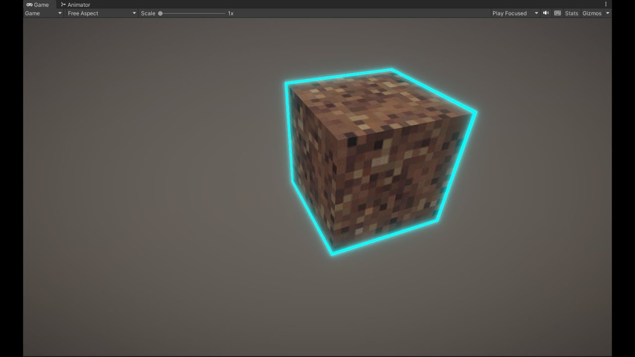
Weird that my highlight shader isnt working like how i want it to work

How are shaders like this one made
Are you following some tutorial per chance?
yes?
Ive tried using raycast and that didnt work and i tried the simple outline from the asset store which also did not work and now i tried this tutorial which also isnt working
Which one?
With all three of those solutions you should try to pinpoint why exactly they aren't working like you expect
Otherwise you're leaving it all up to chance
UVs of the sampled texture are offset by time
the first couple tutorials were how to highlight objects using raycast which is what i want but neither of them worked but no error code and this one fills the object instead of the outlines and Idk what to do
And u would think that the video that used the quick outline asset should work but nope
idk if its bc of my camera or smth else but its getting to the point i wanna cry
There should be a couple of things you should make sure is working
- check if the detection is working, log the detected object see if it return something
- check if the outline shader is working
- try showing outline on specific object when spacebar is pressed...
Now when everything works, you can start combining them
Tutorials and assets usually do work, or you'd see in the comments/reviews that it doesn't
Unless we know what steps you took, there's little that we can do
float4 worldOrigin = mul(UNITY_MATRIX_M, float4(0, 0, 0, 1));
````Shader error in 'HDRP/Nature/SpeedTree8New': 'ApplyWind_float': cannot implicitly convert from 'float3' to 'float4' at line 18916 (on d3d11)```
any idea? i can't fix it at all
it's hdrp
on srp it works with unity_ObjectToWorld but on hdrp it says to use UNITY_MATRIX_M, but when I do this error occurs
and yes with float3 worldOrigin its the same
Line 18916? 😱
Btw, are you sure the error is in the worldOrigin calculation?
Your code looks fine to me, maybe the error is in another place?
hmm wait
oh im stupid
I didnt delete unused input variable
sorry for taking your time
one more thing, I need in my function float4 rotation (quaternion) but i can't find it in shader graph, what's it's name?

Shaders don't typically use quaternions. You pass in matrices and use matrix multiplication instead (e.g. via Multiply node with a Matrix4x4 and Vector4)
Or can use Rotate About Axis for axis-angle rotations.
If you already have a function like that in hlsl code, can look into the Custom Function node too.
I found way to do it without quaternions and im already using custom function thanks
Do you know why I might be getting this error? I don't understand, HLSL has fixed data type right?


Also, now that I'm here, I wanted to ask too if this in shadergraph is normal:

I have over 81K variants!
fixed comes from the older Nvidia Cg language. Unity used to use Cg, now uses HLSL, but you can write Cg compatible code by using CGPROGRAM instead of HLSLPROGRAM, while automatically includes files that define types and functions, such as fixed.
So now it should be half4?
Mhhh interesting
I guess that if I'm using URP i shouldn't be declaring any shader as CGPROGRAM
Could anyone Point me in the right direction on how to setup an image shadergraph so that transparency can be applied along a circle? I have a circle of runic text and i'd like to fade one letter in at the time, figured i'd ask here as a starting point instead of messing around with the wrong UV nodes for hours
If by image you're referring to the UI Image component, you ideally want to use the "Canvas Graph" in 2023.2. For older versions sg didn't properly support UI, though the Unlit may work but only for a Screenspace-Camera canvas, not Screenspace-Overlay.
As for the nodes, Polar Coordinates -> Split G output, may be a good starting point. That should give you a value between -0.5 and 0.5 around the circle. Can then remap with Inverse Lerp (and Saturate to clamp betwen 0 and 1) or Smoothstep.
https://www.cyanilux.com/tutorials/polar-coordinates/

yeah litterally as you answered i dug deep enough into the youtube rabbithole to find a video which included it lol
Might be a good idea to make a specific tut vid on this just so its easier to find, since the solution was so simple..
thanks homie 👍
So I've got this situation where I'm trying to apply noise to world position coordinates and then feeding that into a sphere mask, and it's all working nicely at origin, but when I rotate it it all goes wrong. What I don't get though, is that it should just be using UV space?

What exactly do you mean by "it all goes wrong". I can see you're using sample LOD nodes so is this used for vertex displacement? Are you sure the issue is with the noise?
literally just figured the root of it, as always, I'll struggle with something for hours post a question then finally get there. I'm pretty sure it's ADDing to the world space instead of multiplying
Add makes more sense to me. I think multiply would mean the noise strength is lower near the world origin and higher as you get further away.
Guess it depends what effect you're after.
If you want the noise "aligned" to the sphere, could add the noise to the Radius instead of Position
Hey guys I was working on some LODs and shaders when I ran into an issue, I made trees which use LODs for the stem and leafs. each LOD uses the same mesh for the leafs. For some reason when I use the LODs my shader doesn't seem to be working correct on the leafs, for example: there is no wind, the gradient isnt correct etc. When not using LODs it works just fine
this is the difference, the right one is without LODs and the left one is with LODs. Someone who might know how this is possible?

Maybe the LOD mesh isn't UV mapped / vertex colors the same way? Assuming the shader gradient/wind is based on those.
hmm would be pretty weird but ill check
but the leafs are the same on the one without and the one with LOD, they should both be UV mapped the exact same way
hey guys, so this question may be a bit too specific, but ... I'm trying to implement a custom post process pass, and in my SetupRenderPasses I set the renderer.cameraColorTargetHandle as a field on the pass, but then when Execute runs, the field ends up being null ... but seems only for one frame?
I tried logging this, I see both calls happen in sequence, but when I recompile I will get this to log once
public override void Execute(ScriptableRenderContext context, ref RenderingData renderingData) {
    if (_cameraColorTarget == null) {
        Debug.LogError("Camera target is not set");
        return;
    }
    // ...
}
but it only when I have the shader graph window open ... if I recompile with just the scene view open I don't get this to trigger, but if I have shader graph open it does trigger exactly once on each recompile
sounds like a unity bug?
This question probably fits better in #archived-urp, but do you use if (renderingData.cameraData.isPreviewCamera) return; at the start of AddRenderPasses? iirc I usually use this to avoid some null target errors. (Might be that the renderer is trying to run in shadergraph's Main Preview or something?)
Found the problem, when exporting from blender I applied transforms, making it 100x bigger or smth because I scaled it down by 100. Idk why this mattered tho and also dont really know why it messed up my shaders
oh nice looks like that fixed it, thanks!
Makes sense. In that case the gradient/wind/etc is probably based in object space so will be affected by differences in model scales
dont really see the problem in my gradient tho, when using the non applied transforms model the gradient changes based on position/scale and the mesh with the applied transforms doesn'let the gradient go from top - bottom but from left - right

I'm using URP and tried to bake the lightning from this sphere, but no light bounces or bloom is coming out.
Both objects are set to static, and added post processing on the camera, but no changes.

check if the material is emissive
Yeah the emission box is checked for the sphere
Hi all, so playing a bit more with my graphic equalizer shader, but running into a snag that I can't seem to fix/figure out.
The issue is at the beginning where the platform raises up. As you can see, because I have the green/red gradient texture 'fixed' in world space, it repeats.
Is there a way to fix this? I'm a little stumped 😕


Should be able to change the Wrap Mode on the texture asset to Clamp
Unfortunately not I'm afraid, bars are now solid red. 😦
I still think you should be using Inverse Lerp instead of Lerp in the graph. That might be causing this, not sure.
Specifically, Position -> Split G -> (T input) Inverse Lerp though keeping it Vector3/2 might not matter much given the gradient texture.
Okay, gimme a minute and I'll give it a go 🙂
Does exactly the same thing. 😕

You still have the texture set to Repeat
Should also make sure your properties are set to the world Y values that the gradient should start/end at
HAH!, sorted it thank you. Just couldn't get it straight in my head but your last message helped a lot. Ended up modifying the minHeight and maxHeight properties based on the Y position of the 'platform' 🙂

i just learned that shader graph supports built in!
this looks nice... are you the artist who made this?
Thanks, Yeah basically I'm an artist, but I know a little shader graph
that's some nice work. love the hand drawn textures
who did the art direction?
Me
that's super consistent without being caricatural
anything else you've done?

ArtStation
This is the end of my recent journey over the past 2 months. I'm not a lighting artist or a shader programmer, but I tried my best and learned a lot, so I should mention that the journey was very valuable for me.
older project
nice, but you should use #1180170818983051344 next time
btw, is it possible to get vertex direction or normal from a trail renderer vertices? I keep having 0 even with Generate Lighting Data checked ON
Im trying to putting an HDR into a shadergraph to have better control on its rotation and its effects, I tried some suggestions written here but is not working, any help?
@amber saffron (sorry for ping, you were kind enough to answer me last time)


I've replaced the "Sample Cubemap" node with the "Sample Reflected Cubemap", now I can at least somewhat see the skybox, still need a way to turn the colors to normal and a system to rorate it on the 3 axis


A shader graph shader has all these keywords, but they're not listed as built in keywords in the shader editor: https://docs.unity3d.com/Packages/com.unity.shadergraph@12.1/manual/Keywords.html#built-in-keywords
How can I reduce these?

Mornin' all, I'm working on a simple 'ground displacement' Shader but I'm getting weird results and I can't for the life of me figure out where I'm going wrong.
Could anyone point me in the right direction please?


What's weird about it precisely
It's displacing along the wrong axis by the looks of it. It's okay, I've gone another route as I remembered I cant have accurate collisions using Shader graph
Since world/object position is composed of XYZ and the Gradient Noise is two-dimensional, it takes only the X and Y directions
You can instead swizzle it to X and Z
Ah gotcha. Thanks. 🙂
I'm trying to render this static field of flowers with just an ambient light that is around 45* Degrees towards the ground, any Idea why I get this shadow spots? I've already set the flower themsleves to cast no shadow


I tried to rotate the ambient in way it was more perpendicular to the flower, at start it seemed working but then after another bake these soft shadows returned
is it possible to scale objects through the shader graph?
You can modify vertex positions, so yes, but worth to note that object Bounds and so culling won't respond to changed mesh shape
hmm kk ty
I have a custom shader (vertex snapping) graph. However, when applied the selection outline of the object changes.. why would this be happening?

The object is in the correct/original position but its just annoying, as I can't click on the game object in the scene
You can rotate using the "rotate about axis" node.
For the "turn the colors to normal" part, this is not very clear, try to pass the color through a colorspace conversion node , or dim it by mutliplying the value with something between 0 and 1
Where the rotate node connects to? I dont seem to have any good result when connecting it to the sampler node
It should connect to the sample cubemap node
Did you maybe use "rotate" instead of "rotate about axis" ?

Oh yeah I now can rotate it
got this btw

At the end I found a coded shader to rotate the skybox on the 3 axis, I guess will use that and avoid all this struggle, maybe skybox arent meant to be played with like other materials
thanks, warning solved
still there is the color issue that isnt solved yet
when unity crosscompiles the HLSL shaders to OpenGL shaders does it leave the plain GLSL code in the asset files or compiles it to something like SPIR-V?
The transpiled source code is in plaintext in the build assets. But, the GLSL source is generated not from the HLSL source code, but from the compiled bytecode. This makes it look very different from the source HLSL.
thanks
ive been researching for days and haven't been able to figure anything out. i am currently using SetTexture and SetColor and a bunch of materials in my game. This works perfectly fine in the editor, but just does nothing in a window build. how do i fix this?
These shaders are all custom shaders. I've been trying a bunch of stuff with keywords, but im not even sure I'm on the right track.
hi i have snow texture and i have some rocks. im trying to add the snow texture(paint it) ontop of the rocks. any idea how?
(does this concern shaders? i basically dont know what it is [still new])
Hello Everyone! I'm running into a problem where my shader is working at ground level (near zero on the global y-axis) but breaks at higher elevations. It slides around as shown in the gif (grass made orange to see better) but for some reason, it functions as expected when I get the camera close to it. I have no idea why it is sliding around at all to begin with - I am reletivly new to shaders, but I don't think I referenced anything related to global positioning at all in the code, so I'm not sure why it is doing that. I had a similar problem to this in the past, and managed to fix it by disabling "Static" for the objects, but that isn't working here. As an aditional note, the shader for some reason works perfectly on defered rendering, but breaks on forward rendering... I'm not sure if it is a problem with the shader itself, or some unity settings, so I'm not going to post the shader code now (to avoid cluttering up chat) but will post it if requested. Help would be extreamly appreciated, I am totally stuck due to this. Thanks!

Does anyone know of a method for blurred UI that works with the Quest?
question. I'm trying to make the aplha clip so only some parts of the material is shown is there a way to do this because I been trying for a while a seem not to get it

its using the black for the color but I want the black to be transparent
never mind got it
actually I don't got it
Your alpha clip threshold is really high
Hey so i'm trying to use this shader https://assetstore.unity.com/packages/tools/particles-effects/quick-outline-115488#reviews to outline objects but I noticed that when 2 objects are overlaping each other there onlines collide. I don't want this to happen but I'm compelty new to shaders and have no idea how to make it so that the outline always fullys shows. Any help would be greatly appreciated!

Use the Quick Outline tool for your next project. Find this and more particle & effect tools on the Unity Asset Store.
Greetings ! In shader graph, is there a way to grab every output (or input) in order to plug them somewhere else ? Kinda like the same system as unreal ? Thanks in advance !
If you're referring to outputs with multiple wires, you can drag a selection box through them first to select them all, then click on the selection and drag
https://www.cyanilux.com/tutorials/intro-to-shader-graph/MovingConnections.gif
(discord doesn't like the gif but shows how to do this)
Could also add reroute nodes (by double clicking on a wire). If the outputs come from one of those it's easier to swap the input.
Ahhh yes, was definetely looking for it ! Didn't think about the drag tech ahah thanks :D !
Hello, i'm trying to cover a rock asset i found with snow ontop of it using shaders since i haven't found any other easier way. but all the tutorials use PBR shader and i cant find it. I know now its named Lit shader but when i try to work with it, it just turns the asset purple and nothing happens. anyone know an efficient way to do this?
What render pipeline is your project using and which render pipeline are the shader tutorials for
my project is either using URP or HDRP, they are both applied in package manage so i don't really know
for the tutorial i dont think they said which render pipleline they are using
Being installed doesn't determine which one is active
Project Settings > Graphics> Scriptable Render Pipeline Settings field
No
It's the built-in render pipeline
Shader Graph still works with BiRP but you'll have to add it as an Active Target

I'm trying to render particles on a "render texture" and I want to make it transparent.
How can I make this texture transparent?
I want to change the alpha value but I can't find it.

This is how the render texture is with my camera set to alpha 255.
The other picture is how the render texture is with my camera set to alpha 0.
The material of the particles isnt transparent so it isnt rendering.


I am missing "Override Property Declaration" in unity shader graph in 2023.2
has anyone had the same problem?
should i restart my project using another render pipeline that would be better?
That's a decision you make when you understand what the render pipelines do
alright thanks
Im trying to make a fresnel for my tree, but I can't seem to get a good looking fresnel. Im doing this in HDRP. Someone who knows what I could try to make it look better?


the red glowing thing is the fresnel as it is now
and the normals of my leafs are all sticking up, so it probably has something to do with that, but idk how I can use a fresnel with that
Fresnel relies on rounded normals to give an inner glow look. Even if the normals were correct on your leaves, they would still be flat, so only the leaves that are at an angle from the camera will glow, and then the whole leaf will glow the same amount.
Seems to be there for me. It's at the bottom of each property in the node settings.
(Should mostly only use it if you need Hybrid Instanced, Global matrices, or I guess purposely break SRP batcher compatibility)

hmm kk thx for answer
for me it is under "scope".Maybe because I am using the beta
Probably different in 6000/2023.3 yeah. You mentioned 2023.2 in your question but I guess that was a typo.
Is there any doc or an example of a custom scene picking pass from shader?
I don't see it documented anywhere however shaders generated by shadergraph include appropriate code on several occasions:
Pass {
  Name "ScenePickingPass"
  Tags {
    "LightMode" = "Picking"
  }
// ...
}
#define SHADERPASS ScenePickingPass
  #define BUILTIN_TARGET_API 1
  #define SCENEPICKINGPASS 1
// -- Property used by ScenePickingPass
#ifdef SCENEPICKINGPASS
float4 _SelectionID;
#endif

// -- Properties used by SceneSelectionPass
#ifdef SCENESELECTIONPASS
int _ObjectId;
int _PassValue;
#endif
If you base your fresnel off the view vector in the pixel shader, leave normals should not matter
hmm is the pixel shader some sort of lit shader?
I don’t do shader graph, but if you do most things you do should already be on the pixel shader
One option is you can make some fake normals. Like if your tree is a sphere, each leave can also pass the sphere’s normal as well. This usually results in more cartoon-like trees if you use it for lighting straight out, however this way you can get your fresnel
Say… if you aren’t generating these trees in runtime, you can make an approximation of the shape in blender and pass those normals to your leaf shader
https://youtu.be/DEgzuMmJtu8?si=uY31fmCzmCJKLPzD
Something similar is done in this tutorial
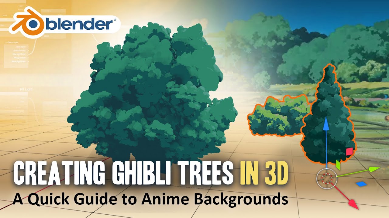
In this video, David from Lightning Boy Studio will show how to create 3D trees in the style of Ghibli films, all in Blender 2.83
You can download a free Blender scene with this tree setup on our Gumroad page :
https://lightningboystudio.gumroad.com/l/RZcQI
You can follow us on Twitter and Facebook :
https://twitter.com/LightningBoySt1
https:/...
thx! ill see if i can make it work
How are shaders, such as a shader for footprints, synced over the network? Or are they not? My assumption is that only player positions are synced and the footprint shaders are done locally based on the position of the players. Is that correct?
Yes
Thanks. I kind of answered my own question there, but needed someone to confirm that was correct so I appreciate it 🙂
So I have a plane here that has been alpha clipped around a circle at the base and then displaced upward with a Cos function.

For some reason I'm getting some very rough looking shadows.
Anyone know why?
Shadows are all kinds of messed up.

Are you modifying the normals as well?
I havent yet, but even just playing around with them isn't changing the shadows.
If the normals match the shape of the mesh correctly then the back of the mesh won't be relying on shadows (and the resolution of the shadow + the bias) to be dark
Hi all, what would be the best way to 'blend' two Normal maps together? (I've got 2 versions of the same texture set with one version 'on top' of the other but rotated 45 degrees). I've tried the Normal Blend node, but it makes the normal map look like complete ass. 😕
I'll give it a try. What do you mean by the back of the mesh exactly?
I guess I just dont understand what I'm looking at. Why do the shadows looks so poor here?
heya, I've been following this tutorial (https://www.youtube.com/watch?v=IZAzckJaSO8) and have it functioning properly, but I'd like to make it so each hexagon of the surface appears or disappears all at once. atm the alpha appears like so in the screenshot, where it blends across the hexagons instead

is anyone aware of a method to do this? ideally without using surface normals but that is an option if nothing else works
Both areas here should be dark; the one on the left largely is (though the fade is jagged because it's limited by the resolution of the shadow texture and offset by whatever bias is added), but the one on the right is lit up, because it doesn't know it's facing away from the light and the shadow texture says it's in the clear.

Why do they look so low resolution? I can understand it being in the wrong area, but why does it look horrible?
If it uses flat normals, I think a Dot Product with a direction towards the collision point should give you appropriate alpha values per-hex/face. (Could also bake those flat normals into UV channels if you need smooth ones too)
Or if you want to avoid normals, could also bake pivots of each hexagon into UVs and use those against the sphere check (in Coords port). Kinda similar to this fracture effect but controlling alpha rather than used for displacement.
Because they depend on the resolution of the shadow texture which has to cover a large area at once
You can shrink the distance over which shadows are cast and increase the resolution of the shadow texture and it'll look less bad
Is it because the plane itself is flat and it's getting stretched across this deformed shape?
normals are alright, I'm just trying to avoid using screenspace normals since those are a bit of a pita (I had to go through that recently for an outline shader)
I guess my confusion is getting the alpha value consistent across the whole face? it's flat-shaded atm but the alpha value is applied after the fact in the shader

in this sphere mask part
I assume I need to multiply this by some kind of stepped normal value but I'm too inexperienced to know what that is
You can use cascaded shadow textures--if ur on urp or hdrp idk if built-in has that
Indeed, you need a consistent alpha value across each face. Your current setup uses the Position node which is different per fragment/pixel, hence it's fading along it rather than the whole face.
Hmm.. since the shield is a sphere, you might just be able to swap that out for the Normal Vector (object space) and convert the SphereCenter/Radius/Hardness properties to be object space too.
Otherwise look into the methods I mentioned in the last post.
oh, actually

this is the model itself, it has these faces baked in already
but let me try that, tyvm
True, but ultimately you want to get areas facing away from the sun to be dark from their normals and use shadows where they're needed, not the other way around

worked like a charm
thank you very much yo you continue to be the best unity shader person
I'm kind of confused because this guy doesn't modify the normal and his shadows look peachy.
https://www.youtube.com/watch?v=poi10W6LHJo&ab_channel=LlamAcademy

Learn how to create 2 types of waves - linear and radial/circular waves in ShaderGraph with Maths!
The most common application for waves is water or liquids, but you can apply these throughout your game or integrate them with other shaders to get cool effects, like Wind.
If you are new to ShaderGraph, be sure to check out the Vertex Displacemen...
Is anyone experienced with buffers?
I'm working with some compute shaders. I want to use an append buffer, but have some complications so the workaround I've been using is using InterlockedAdd to get a synced index and then writing data to that index in a structured buffer.
Is this significantly slower than an append buffer?
I know the append buffer itself also has a hidden index value, just dk if there's some optimizations in incrementing it
The shadows at 9:05 look a bit dubious; the reason it looks good most of the time is because in the demonstrations, the light comes in at a fairly steep angle (so there aren't many shadows) and the waves are small (so they don't cast many shadows). Viewing things from the light direction also helps.

With unity builtin, when a camera is far from an object, is it possible for the generated motion vectors to be of objects that are not the closest? So the motion vectors are instead made for an object that should be obscured by a closer object, instead of being made for the closer object? in deferred btw
ITS DYNAMIC BATCHING
Hmm fair enough then. Well... now the question is, how do I calculate the normal vector along a sine wave 😛
https://www.desmos.com/calculator/fegsqy6h4x
The normal is the gradient of whatever height function, divided by sqrt(1 + gradient^2) (and the z component is just 1/sqrt(1 + gradient^2))

Desmos
Is there are decent resource for someone new (me) looking to work with shadergraph for a 2D game?
Most shader graph tutorials can give you the basics. Just see the 3D model as a plane/quad and you got 2D shaders :P
Hello guys!
I'm starting a 2.5D project similar to octopath, and I already got the multidirectional billboard shader going , but i'm looking to try to make my sprite renderers cast shadows as well. I've looked into some videos, but none of them worked, tried to do multiple passes but also didnt work. I've used the debug mode on the inspector and set my sprite renderer to cast shadow but no use eighter.
This is my shader atm:
https://pastebin.com/LWDGeMqZ
Pastebin
Pastebin.com is the number one paste tool since 2002. Pastebin is a website where you can store text online for a set period of time.
I dont discard the idea how adding another gameobject with a diferent shader just for the shadows if need be
I don't work in built-in RP but, have you checked if this casts shadows without the billboarding? If that interferes, you may need to write the shadow caster as a separate pass rather than using addshadow.
Also you use AlphaTest: _Cutoff but don't have that property at the top of the file. e.g. _Cutoff ("Alpha Cutoff", Range(0,1)) = 0.5
I removed it on the paste, Yeah i tried to write a separate pass for the shadowcaster but i didnt get it to work tbh
It should be URP tho
Oh right. I throught it was a surface shader because of this line
#pragma Lambert vertex:vert AlphaTest: _Cutoff addshadow keepalpha
That is doing nothing, you can remove it
If you want to cast shadows in a vert/frag shader you definitely need a separate ShadowCaster pass. If you're in URP one of these templates might help - https://github.com/Cyanilux/URP_ShaderCodeTemplates
Or look at the shaders URP already provides for reference. https://github.com/Unity-Technologies/Graphics/tree/master/Packages/com.unity.render-pipelines.universal/Shaders
Though it might be easier to just use a shader graph
Ok i'm checking it out, but i see that they are HLSL programs instead of CGPrograms, can i mix them both?
i'm having a bit of trouble getting it to compile correctly. Its giving me an error of unrecognized identifier on a different file: commomMaterial.hlsl
Might be okay to mix them between passes, I haven't really tried. But ideally you shouldn't.
In short, CGPROGRAM includes some stuff for Built-in RP, but that causes conflicts when using URP includes (like #include "Packages/com.unity.render-pipelines.universal/ShaderLibrary/Core.hlsl"). HLSLPROGRAM avoids that.
Using URP's shader library is mostly important for making shaders compatible with the SRP Batcher (to optimise setup between draw calls). Though that only supports sprites in 2023+ so if you're on older versions might not be that important.
Yeah, im in. 2022 version
Coding shaders is a bit of a pain in SRPs so I'd see if a shader graph can do what you want first. The Sprite type graphs probably don't allow shadows, but the Unlit or Lit graphs should.
struct Attributes {
                half2 uv : TEXCOORD0;
                float4 positionOS : SV_POSITION;
            };

             struct v2f {
                float4 pos : SV_POSITION;
                half2 uv : TEXCOORD0;
                float4 positionCS:  TEXCOORD1;

            };


            v2f DisplacedShadowPassVertex(Attributes input) {
                v2f o ;
                // Example Displacement
                input.positionOS += float4(0, 0, 0, 0);

                o.uv = TRANSFORM_TEX(input.uv, _BaseMap);
                o.positionCS = GetShadowPositionHClip(input);
                return o;
            }

            ENDHLSL
this is how im at atm, i just dont have the transform_tex definition
It is casting shadow now! (right one with the shader), now i just have to deal with the alpha probably

May need to override the ShadowPassFragment with your own function. Sample _MainTex and use clip(tex.a - _Cutoff);
something like this?
half4 ShadowPassFragment(v2f i) {
                half4 col = tex2D(_MainTex, i.uv);
                clip(col.a - _Cutoff);
                return col;
            }
its giving me "function return type missing semantics"
Sorry, i cant find docs for this type of things
ok, it was just adding SV_Target. If i raise my _Cutoff above 0 shadow just dissapears
            half4 ShadowPassFragment(v2f i) : SV_Target {
                half4 col = tex2D(_MainTex, i.uv) * half4(10,10,10,10);
                if (col.a > 0.2) {
                    discard;
                }
                return col;
            }
``` seems like nothing changes when i change this functionMake sure you have _MainTex in the properties at the top of the file. Maybe also rename the function and the one in the #pragma fragment just to make sure it's using the correct one.
i do have the MainTex and also
#pragma AlphaTest: _Cutoff
#pragma vertex ShadowPassVertex
#pragma fragment ShadowPassFragment
Okay, disabling cast shadow on the sprite renderer disabled the shadow. so maybe the shader isnt doing anything?
got it working dude, thanks so much!

Hello I need help. I found this online. I copy it and still mine doesnt look the same...


Below is mine. Above the one I've found online. Also my preview won't show, no mather what i do?
Turn off auto clipping
Where is that setting?
Is polybrush still the best way to paint vertex colors (materials) onto meshes in Unity? I've heard it's problematic in that it works by creating a duplicate of the mesh and paints onto that? Which is problematic because if you update the original mesh, it doesn't update the new dynamic duplicate mesh that it created?
They mean "Alpha Clipping" under the graph settings. Also change the Depth Test to LEqual, not Equal.
And even if the main preview shows nothing, save the graph (top left corner) and check it in scene/game
Yes my bad 🙏
I haven't used polybrush that often, but iirc you can export the mesh if needed.
According to the docs it looks like you can also use additional vertex streams so it's separate from the original mesh - https://docs.unity3d.com/Packages/com.unity.polybrush@1.0/manual/component.html
Though I imagine with that you'd still need to keep the vertex count the same. Not sure how it would act if you added vertices after painting.
It's working great now! 🙂 Thanks so much!
No worries! I love the help!
@regal stag Not quite understanding the description. So if I want to avoid it making a clone and actually write to my mesh I should use 'additional vertex streams' over 'overwrite'?

I don't think either option can actually edit the model file. For that you'd probably need to use the Export Mesh Asset button.
If it's something you need to do often, it might be better to paint directly in Blender or something
Yeah, that's what I'm doing at the moment with Maya. Ideally would be nice to be able to paint within the context of the scene so I know where exactly to paint, overwise it's a bit of back/fourth and tweaking to make sure everything lines up as I want it to. The export mesh asset is a nice option but it adds an extra step to the pipeline. Works as expected in Unreal, I can update VC in Unreal and tweak mesh in Maya and it holds the info pretty well. Obviously any major changes and you have to repaint but only the area that was heavily edited with additional verts etc.
is there a keyworld / way to get entire object's world space position (not per-vertex)
hlsl
I tried creating this shader using SDF and it looks pixelated in game view. Any Idea how to fix this?

float4 frag (Vert2Frag i) : SV_Target
            {
                uint maxHealth = _HP + _Shields;
                float numberOfSections = maxHealth / 25;

                float numberOfHPSections = _HP / 25;
                float numberOfShieldSections = _Shields / 25;

                float healthAtFragment = lerp(0, maxHealth, i.uv.x);
                float sectionOfFragment = int(healthAtFragment / 25);

                float4 fragColor = lerp(_HPColor, _ShieldColor, sectionOfFragment >= numberOfHPSections);

                float healthMask = healthAtFragment < lerp(0, maxHealth, _Health / 100.0);

                float2 coords = i.uv;
                coords.x = coords.x * numberOfSections;
                coords -= float2(0.5,0.5);

                float mask = step(0, calculateBoxSDF(coords, float2(0.5 + sectionOfFragment, 0.5)) + 0.05);

                float4 healthColor = lerp(float4(1, 1, 1, 0.05), fragColor, healthMask);

                return mask * float4(0, 0, 0, 0.6) + (1 - mask) * healthColor;

            }
The text and the lines are smooth as they are not included in the shader
I think it has something to do with Anti Aliasing but idk how to implement that because I am not using textures
You'd mainly want to look into removing the step(in, edge) function usage. Can use smoothstep(min, max, in) (with a small difference between min/max) or methods that use fwidth to achieve an in-shader/local anti-aliasing.
e.g. https://www.ronja-tutorials.com/post/046-fwidth/
If there's no dynamic/static batching, can extract it from the model matrix. e.g. unity_ObjectToWorld._m03_m13_m23 or UNITY_MATRIX_M._m03_m13_m23
It works but there are white outlines in the inner portion too which looks weird.

thats because of AA too right
Im using 2D Tilemaps and creating seasons. And really don’t feel like recoloring my Tilemaps for every single season, is there a way i can have shaders for each individual Tilemaps (plants, grass, dirt) to adjust the hue instead ?
? how you use webp in unity editor (can you load webp like in blender - keep save as file: Lit_Text.webp but without convert png) ?

@deep moth Hey, so, you know that issue I had forever ago where there was a black bar thing at the top of the screen? Well the way I got around that was originally by starting the game, stopping it, then increasing the size of the scene view. But I just launched unity, and the issue is 10 times worse now. All I did was create a second camera in the scene outputting to a render texture. Is the post processing being applied twice? First image is the before enabling the shaders. Second image is after.


That doesn't look like AA, AA would make it pixelated--it seems like a shader problem
I can't get rid of the second camera because I need to place the UI from the render texture on this radar object.

how can I make this effect in the shader graph? I have a texture with the areas I want deformed on different color channels, and the distance from the "wall" as a float. The arms looks normal from perspective

thank you
Hmm. I don't know why that's happening! It's interesting that it only shows up with a second camera. Do you know how to use a frame debugger?
It would answer questions like is it rendering twice pretty readily.
You can find it under https://docs.unity3d.com/560/Documentation/Manual/FrameDebugger.html
The Unity Manual helps you learn and use the Unity engine. With the Unity engine you can create 2D and 3D games, apps and experiences.
At first I thought it was an issue with how the outline shader grabs the width and height. But now I'm not too sure
Ill try out the frame debugger rq
Does anyone know why I can’t access the zbuffer directly instead of _CameraDepthTexture? I believe it has to do with how it’s not synced with any thread, however every pixel should be written to by only one thread, and if I’m only reading that specific pixel on the same thread I edit it there should be no racing issues
It appears to be acting strange from very early in the process.


I can't figure out why its acting that way
I can't find anything online for it
Might not be that helpful, but I've always just seen reading to a buffer currently bound as a render target as "undefined behaviour". It's likely very hardware specific so even if you get it working on one gpu you can't be sure it'll work elsewhere. Better to keep using the depth texture - sometimes that's created via a prepass to prime the depth buffer anyways.
Hm I don't know off the top of my head! You might have to start taking pieces out until you find the problem. Do you think it's related to the normals? I thought it was weird that it needed a separate texture sample to check if we were looking at the sky.
It could be related to that?
I feel like this is usually more of a IK setup than being shader based
I’m modding the game with a shader change, which is why I need to recreate it. It’s just used to fix shadows since the player isn’t actually getting moved to grab the rocks
Ah well... I don't think we're meant to help with anything modding related in this discord. You may have to ask elsewhere
Yeah I can see that maybe some gpu architecture runs shaders with the same queues in parallel. I was just hoping because otherwise I need to manually blit to the _CameraDepthTexture through a command buffer because I need the depth info from the opaques for the transparent, and the transparent depths for some SRPs.
On that note I've done some research, I believe this is the proper command...
cmdBuffer.Blit(BuiltinRenderTextureType.Depth, BuiltinRenderTextureType.CameraTarget);
Hi, I'm very new to shaders and I'm trying to set a particular colour based on the height of the object, now, all of the logic seems to work perfectly fine, except for when the blend distance is too low, the colours start acting weird, get significantly brighter / darker. Not sure what causes this, and any insight would be appreciated. Lmk if you need any more info.


To clarify, colours get more exaggerated the closer to 0 the blend distance is
Thats what I was thinking too, but then I turned off the outlines and the posterization shader is doing it too.
This is the scene view with just posterization enabled

All the shader does is this

So I don't get why its doing that.
Oh interesting!! Does it show up in builds?
Helloo
This is my first time with shaders
I created a glow shader, but the effect doesn't show up

I added a volume to my cameras but it only shows on the scene view, not on my game view


Can someone tell me why this shader applies a kind of gradient to my colours, it gets very dark at the bottom and very bright at the top.

check you groundcolor
the colours are fine
I do this with multiple colours and all of them have it
the only time they don't, is when I take out the transitioning, so the entire lerping part of it
Wrapping my head around shader graph and just sort of playing around. This is probably about as basic as it gets, but I"m just using tiling and offset plus some cosine waves to make a sprite move up and down, but my sprites are getting cut off, depending on the distance the shader makes the sprite travel.

I was thinking maybe it was the border size of the sprite itself, but I remade one of the sprites with a massive amount of vertical space above and below but it didn't change anything
nm, just figured it out
Mesh type set to Full Rect on the sprite solves it
So the border size was the issue, but I suspect that 'tight' mesh was just ignoring the extra border I made around the sprite.
if the "blocks" text that needs to be moved is a single mesh, I'd must rather just move the vertices up and down as it would potentially be bit faster and you wouldn't need to care about the padding around the elements (more padding also generally is more work to be done for the renderer because the transparent pixels must be dealt with too). that way the actual mesh moves rather than the pixels inside the mesh
#archived-shaders message this is the fragment shader do you see anything? It doesn't happen if I only use step instead of smoothstep
You need a Saturate to clamp between 0 and 1 between the Inverse Lerp and Lerp
Tried following this article for a more generic solution.
https://www.ronja-tutorials.com/post/015-wobble-displacement/
Summary So far we only used the vertex shader to move vertices from their object coordinates to their clip space coordinates (or to the world space coordinates which we then used for other things). But there are more things we can do with vertex shaders. As a introduction I’m going to show you how to apply a simple sine wave to a model, making i...
Still getting some strange shadows though.

Check if Post Processing is enabled on camera. If you still can't get it working best to ask in #💥┃post-processing channel
Might be that the mesh doesn't have the resolution at that peak
Well my concern is more that the shadows still look extremely grainy, and are incredibly dark.
You could try increasing the bias in the shadow settings
Though to be fair I'm pretty sure I'm doing this incorrectly given the look of the normals (currently outputting them as color).

Ah, that does look dodgy
This is the graph, which I'm pretty sure is a proper recreation of the following code.


Your add and multiplies at the start are the wrong way around
Also instead of the Split->Add->Combine, you can use Vector3->Add. Would keep connections cleaner

This looks inverted.
Try flipping the inputs to the Cross Product
Actually might be the subtracts before that
One Minus the end 🙃

2 questions.
- It still kinda looks grainy.
- Why does the shadow rapidly get brighter as I zoom out?
I think Negate makes more sense here

Oh wait I see what you mean.
just this instead

im trying to make my shader able to scale my UVs so I can get bigger leafs for a tree shader, but I have no clue as to where to put that thing at the top in my shader. Do i put it before/after my object position, do i multiply/add it? I have tried out a lot of things but nothing seemed to work

You connect this in the "UV" input of a texture sample node in the fragment shader
But that's probably not really what you want.
If you tree is a 3D object, with already working UV and texture, to make the leaves bigger, you need to actually scale the mesh.
But not the whole tree mesh, only the leaves themselves, relative to their "local" pivot. And to do this, you need to have that pivot information
Unless the leaves are individual meshes
yeah but the leafs and the tree trunk have seperate meshes
Ok, well, to scale a mesh in the vertex shader it's as simple as : object position = object position * scale
ill give it a try
this does indeed scale the leaf mesh in its whole, but since its relative to the pivot point of all the leafs it also goes up while scaling
That's what I mean with the "local pivot"
You will need this information in the vertex shader, usually this is done by storing the data in the vertex color of the mesh
Then you can scale around that pivot by doing : objectPos = (objectPos - pivot) * scale + pivot
But then wouldn’t it be easier to scale just the uv space instead of the whole object?
If the mesh has the "space" for the scaled texture, yes, but I guess that the leaves mesh is tightly wrapping around the texture to limit pixels overdraw. If you only scaled the UVs (and you would still have the pivot issue, but in uv space then I guess), you will end having leaves being "cut" by the mesh
It should be ok, the unwrap for the leafs is a square which fits perfectly in the 0-1 uv space
So if I just scale every uv separately it shouldn’t give any issues
Up to you to try
You probably still want to scale by the leaf "base" in uv space (like, bottom center if the leaf is oriented up)
I will check
Thanks
No it doesnt show in builds, but the shader itself also doesn't show in builds.
Oh that's not good. You probably need to add it to always include.
Most likely, could be because I had to delete the library folder
I added it to always include before.
I don't think deleting the library would get you in any trouble!
Could be something else. You might wanna use a development build and check the logs.
Alright, once I get home I'll check it out. Though I still don't see why the pixels are squishing like that in the editor.
It looks like the image is being squished to fit half the screen instead of all of it.
Ohhhh! I was running into that too. I'm not sure what that is...
The squishing
That really bothered me but I never quite nailed it down.
Seems like the kind of thing you'd solve in c#
I'm pretty sure the issue cause by the outline shader is caused by the same thing.
So if we figure it out in c# we could probably solve both problems.
There's a literal toggle for Post Processing in the Rendering section JAJAJAJAJA
Oh my God the amount of time I spent yesterday figuring what was wrong JAJAJA
when unity exports "ShaderLab" shaders into GLSL theyre supposed to be raw GLSL, but is it only for the new version or also older ones like 2020.x.xx
yo Guys. i need some shader magicians here.
I'm trying to make a multidirectional billboard shader that is able to take into account
- A character's movement direction in WS (passed to the shader from C# code)
- The camera's view direction
And then calculate the correct UV coordinates for a tilesheet.
The tilesheet has diferent directions going down from the Y axis(front, front-left, left, back-left, back...), and animations going forward on the X axis
The animation part is working already, the billboard as well.
I'm just having a lot of trouble calculating the uv.y coordinate from movement direction and view direction.
I tried using the dot product, tried using atan2 function, i've been on this for some hours now and i just cant get it be right.
If any of you magicians could help, it would be much apprecciated!
So.. code here
    float2 dotp = dot(normalize(_WorldSpaceCameraPos.xz), normalize(_MoveDir.xz));
    float angle = dotp * RAD2DEG + 270; //some offset here
        int yIndex = (int)angle / SINGLEFRAMEANGLE;
        float frame = _AnimFrames - (1 + round(_Time.y * _Speed) % _AnimFrames);
        o.uv = float2((v.texcoord.x + frame) / _AnimFrames, v.texcoord.y * UVOFFSETY  + UVOFFSETY * yIndex );
For some reason, clockwise rotations are kinda working, but counterclockwise arent
im doing this on vert btw
I found something online and it works, but its a bit buggy.
This is what I added to the C#: ```cs
int screenWidth = camera.actualWidth;
int screenHeight = camera.actualHeight;
if (source.rt.width != screenWidth || source.rt.height != screenHeight)
{
RTHandles.ResetReferenceSize(screenWidth, screenHeight);
}```
ah nice!! what's the buggy part?
It glitches out a bunch
moving the viewing of everything down or something weird
This is how it looks in play mode.

Unity Forum
I'm not sure if anyone has encountered this before, but it seems custom post processing effect do not align scale with the sceneview nor any camera...


GitHub
A first person multiplayer shooter example project in Unity - Unity-Technologies/FPSSample
have you tried using the drawfullscreen method they use there?
it seems like the documentation I sent was outdated w/ the blit
here's the render function from the new documentation
    {
        if (m_Material == null)
            return;

        m_Material.SetFloat("_Intensity", intensity.value);
        m_Material.SetTexture("_MainTex", source);
        HDUtils.DrawFullScreen(cmd, m_Material, destination);
    }
Thats what I already have though?
public override void Render(CommandBuffer cmd, HDCamera camera, RTHandle source, RTHandle destination)
{
    if (m_Material == null)
        return;

    m_Material.SetFloat("_Intensity", intensity.value);
    m_Material.SetFloat("_StepCount", stepCount.value);
    m_Material.SetTexture("_MainTex", source);

    HDUtils.DrawFullScreen(cmd, m_Material, destination, shaderPassId: 0);
}```I don't get why the post process is resizing the render?
I'm already using that :(
noo
: (
usually when I have problems like that its some kind of order of operations problem -- like im somehow grabbing the wrong texture in the list. This one is pretty strange.
Yeah, I dont get it. It is just resizing the image wrongly.
Best way to render grass in mobile?
I am using alpha cards (billboards) , from a free unity asset from polytope studio , it still lags in mobile, is there any alternative ?
NOTE- idk anything about programming shaders and seeking any premade asset
Thanks, that was it! I had assumed inverse lerp would clamp itself, but apparently not. Thanks again.
You should use the profiler to figure out the bottleneck first.
Pivot point? Like applying a rotation to the model? That's the object space position of 0,0,0. It is set in the modeling program. All other vert locations are relative to that.
You can then, say, transform that 0 vector3 into world space by applying a matrix transform to it...Theres a node for it, sort of.
https://docs.unity3d.com/Packages/com.unity.shadergraph@16.0/manual/Transform-Node.html
So you'd transform an input of (0,0,0) in object space to whatever you're after...like world space or something.
Any idea why my shadow caster pass is telling me "no matching 2 parameter intrinsic function" for the tex2D function?
                v2f o ;
                float3 objWorldPos = normalize(mul(unity_ObjectToWorld, float4(0,0,0,1)).xyz);
                float3 fromCameraToObject = normalize(objWorldPos - normalize(_WorldSpaceCameraPos.xyz));
                float angle = SignedAngle(fromCameraToObject , _MoveDir , float3(0,1,0)) + 180;
                angle = fmod(angle, 360);
                float mappedAngle = floor(angle / SINGLEFRAMEANGLE) * SINGLEFRAMEANGLE;
                int index = round(mappedAngle/SINGLEFRAMEANGLE);
                float intervalSize = 360 / _nDirections;
                float frame = _AnimFrames - (1 + round(_Time.y * _Speed) % _AnimFrames);

                o.uv = float2( (input.texcoord.x+ frame) / _AnimFrames , input.texcoord.y*UVOFFSETY+UVOFFSETY*index);
                o.pos = GetShadowPositionHClip(input);
                return o;
            }

            half4 ShadowPassFragment(v2f i) : SV_Target {
                half4 col = tex2D(_BaseMap, i.uv);
                if (col.a > 1) {
                    discard;
                }
                return col;
            }
In URP code it's usually
TEXTURE2D(_BaseMap);
SAMPLER(sampler_BaseMap);
// (might already be defined like this in an include file)
...
half4 ShadowPassFragment(v2f i) : SV_Target {
   half4 col = SAMPLE_TEXTURE2D(_BaseMap, sampler_BaseMap, i.uv);
...
More info - https://www.cyanilux.com/tutorials/urp-shader-code/#texture-objects
Somewhat related - https://docs.unity3d.com/Manual/SL-SamplerStates.html, the macros here basically switch between the DX9 or DX11 styles depending on platform
Thanks!
Do you think thats whats happening here?

Hello everyone, im having the typical issue of mapping a quad onto a sphere and wanting the least distortion... In my case I want to map a voronoi noise on the skybox. I thoght of making my own triplanar and multiplying the noise by each rgb value, this way i would map the noise on each face (i dont mind if it repeats). But this doesnt yield the result I expected, it still has a seam but i cannot understand why, in theory the same noise is mapped to each face(?

In fact, if i plug the output of normalize into the output, it draws the spherical cube correctly
int appendInd = 0;
InterlockedAdd(structures[COUNTER_IND], 1, &appendInd);
structures[appendInd + START_IND] = newStructure;
Does anyone know if I can access addresses directly like this in a shader?
does "ref" work?
... does ref exist in hlsl? I think that's a C# thing, unless I'm wrong
so InterlockedAdd(structures[COUNTER_IND], 1, out appendInd)? I'll try that
yes
It maps it correctly

I figured it out--you can just pass it in normally like
so InterlockedAdd(structures[COUNTER_IND], 1, appendInd) and it will pass by reference automatically
Hey guys.
I feel like i'm pretty close to finishing this shader i've been working on for the last 3/4 days. I opted to go the shader graph way now because the project is in URP and its a pain to get documentation on it.
Im trying to do a billboard shader that is able to take in a spritesheet as main tex and then choose the correct sprite to play based on the camera direction and position of the object as well as time. Kinda like octopath traveler or ragnarok online
So.. my spritesheet for test purposes is 512x512 and it starts with the forward animation (-y) , then has 7 more directions for a total of 8 and 6 frames for each animation(x axis)
The billboard part is done, i need help with 2 things now:
- Getting the correct index for the flipbook
- Adding shadow to the shader graph
This is my process up until now:
First image: Getting camera and object worldPos, then going the ACOS way to get the angle between said vectors in the xz plane, then multiplying it by the n_directions in my sheet to hopefully be able to move downwards on the sheet Hey guys.
second image, using time and modulo to get the current frame index which then i add on the flipbook part (3rd image)
Right now my problems are:
- No shadow :<
- Indexation for the flipbook is wrong, i.e., it almost plays the animation correctly but the first(or last) frames bleed onto indexes for other animations(bleeds onto the y axis)
Please, would surelly appreciate the help on this, its driving me nuts!


does anyone know how to fix this? this is my first time writing shader code


im trying to make it change color based on health, but currently the shader bug makes every block i attach it to the null purple color

Sorry if I'm not asking the correct question or making it clear what I'm trying to do. I want to take my 3d character and render him out to look like pixel art, example being dead cells, but I want to do that in real time so I can have procedural animation. My first approach was a render texture with small dimensions, and slapping that on a quad. But I am left with everything that is behind the player also being made low res. My question is, how would I make a shader that only renders on-top of the player model, and ignores everything else captured by the render textures camera. Please ping me with any resources/article or just any insight. Thanks!!
you need to declare the _Color, like fixed4 _Color
With a custom shader you don't have to use a custom texture. You'd just have to change how the texture is sampled.
Alternatively, render the character into a render texture by a separate camera and the rest of the scene by a normal camera
try using shaded wireframe mode, to check what is cropping the light volume.
Also you might want to use frame debugger to find what might be the cause
I'm not sure if doing whole this inside a shader would be a good idea (both complexity and performance wise), seems like doing the calculation inside a script and fetch the result offset should be easier
How can I fix my shield mesh from looking weird with the shader? I mean the middle part of the shield


Fix it in the mesh instead
You have overlapping geometry due to non-bisecting mirror modifier
how
Enable bisecting or don't have geometry crossing the mirror line
Works now thanks, do you know how I can make it so the hex texture doesnt end in the middle but at one side? They`re merging in the middle
I suppose you're asking how to UV map the texture to not have a seam in your mirror line
That will require you to understand UV mapping / unwrapping
Yeah i might opt to go that route
Could you elaborate please?
I've tried using frame debugger and couldn't figure it out. But I'll try the shaded wireframe mode.
This is what the scene looks like with shaded wireframe and without my custom post process.

This is what it looks like with my custom post process

It seems to shrink the rendered image.
I need a way to prevent this.
Also, @deep moth I tried disabling post processing on the second camera and the issue persists.
is Unity shader.SetX() smart enough, to skip unnecessary updates?
e.g. when I want to update an uniform every frame, does it remember last value and avoid sending it to GPU if the value didn't change?
or is it completely up to me to assure updates are not needlessly made?
Hi everyone! Unity noob learning how to code a custom shader and I have a problem. In Unity, when I double-click a newly-created shader file, nothing happens. VS is supposed to launch so I can code right?
are you double-clicking the .shader asset?

you can also try clicking topmost "Open" button in the inspector when shader asset is selected
yes, thats the icon. I tried double-click and then the right-click>open. Still nothing
@broken sinew
hmm, try to check if you can double-click regular C# scripts by double click
and if you have the editor set up in the... Preferences?
Yes, Edit > Preferences > External Tools > External Script Editor
I see this

yup, select the external script editor and it may work
is that devenv good enough to code shaders, or does it need to be in VS?
I don't even know what it is, I just use Rider ¯_(ツ)_/¯
I recommend VSCode as a free IDE though
you can get an extension for authoring shaders and whatnot
Sorry this is literally my first time doing this, I do not know much of the terminology.
ok so VS is an option in the dropdown menu, do I have to do anything else here?

I will look into that
and if you are a student you can get a free Rider license from Github Educational Pack (google it). Rider is superior imo.
well, I am following what's supposed to be a "simple" youtube tutorial. When they double-click it goes into a white screen with code. I dont get that, probably because I installed this today for the first time.
using VSCode sure it's faster but you need to install extra extention, idk if they update this tho
dont forget to restart your device after installing
huh, guess I'll do that now 😁
I was having the problem with just one camera too.. Do you remember what you were doing when it first happened?
I created the shader and added the posterization nodes to it and it started happening
The way I got around it before was by starting the game and it would fix itself
but that doesnt work anymore now that I have two cameras.
Also, for the outline shader it appears to be mixing the two cameras together.
Since this is what the second camera sees

And this is what the game looks like with just the outline shader.

You can faintly see the radar covering the whole screen
Its more defined when disabling the fog though, since the outline shader renders before the fog.

But the issue happens much less without two cameras
In fact, with only one camera, the issue only happens in the scene view.

But I can't get rid of the camera since I need it for the render texture displayed on the radar.
Im having an issue with Shader Graph. After multiplying with a rectangle, i am unable to connect to the position node.
I am using this to add rocks to a terrain, but rocks at the edges would show the edge.
hey so I made a simple outline shader and am having issues with some artifacts only on certain sprites, can anyone tell me why?


iirc the Rectangle node uses fwidth in it's calculations which is fragment shader only, so the node can't be connected to the vertex stage ports.
But you can replicate the calculations it uses. See https://docs.unity3d.com/Packages/com.unity.shadergraph@17.0/manual/Rectangle-Node.html
But probably replace the 1 - d / fwidth(d) with something like step(d,0);
I'd assume the sprites are part of a larger sprite sheet and other parts are leaking into the neighbouring sprite due to the offsets. You may need some extra transparent pixels as padding
yes that is the issue, do I need to modify every sprite sheet or is there a way to do that in the shader
If the sprites are aligned to a grid, technically possible if you mask the texture samples to a specific rectangle. But would mean passing in the amount of rows/columns and a tile index which requires different materials per sprite.
ah okay, whats the easiest way to modify the sprite sheet then? anyway to do it in unity or just change it in asperite and put it back in
Would be using external tools yeah
I suppose it might also be possible to just edit the sprite mesh a little so the upper corner isn't drawn. (it's the "custom outline" dropdown in the Sprite Editor window)
Don't know if that'll work for all cases though.
yeah its just easier to fix them in an editor
Aseprite can import and export sprite sheets for rearranging, allowing you to define order and even padding
is that different than what im doing? im just putting the png into asperite and changing the canvas size then moving the stuff into the new area
I assume it's what you're doing but sounds like you're doing it the hard way
whats the easy way?
Importing and re-exporting sprite sheets with the required padding
thats what im doing no?
My point is exporting lets you define the padding automatically, no need for moving any stuff manually
is "exporting" refering to something different
same thing but automated
thanks
I actually forgot to test if it happened in a build, and no, it doesnt.
I guess that's good to know. I wonder if it would happen again if resized in the build? I also noticed that only having the scene view or game view open one at a time works.
It's really weird that its an issue reproducable w/ their example code.
Unity Forum
I have a script that needs to render things in world space after post-processing effects.
This works perfectly using a custom HDRP pass with...
this one was what mine looked like
I asked in #💻┃unity-talk because I feel its Unity or C# related. And I found out that the shaders are trying to force 1080p resolution
800x600
Is there any way to manually cull faces through shaders? For example, I want to be able to walk around a tree and see it normally, but cull the backfaces based on the camera, now this isn't typical backfacing because you can still walk around and see the other side of it as you normally would.
What's the point of it though?
Just use a double sided shader and it'll do just that.
because then you're rendering everything, even if you can't see it. The tree was just an example, a better example would be hills
imagine there is a hill and behind it a mountain overshadowing it, you don't want to render the back side of the hill nor the mountain, only the front side that the camera can see
which means I'd need a solution which actually removes the verts from the renderer instead of just, lets say, turns them transparent
You don't render it normally. There's something called depth testing and depth buffer. When a pixel is about to be rendered it checks it's depth against the depth buffer, and if there is already a closer pixel, it doesn't get rendered.
This kinda sounds like it would introduce more overhead making the performance worse, not better.
Unless you have a very specific case where the scene is always meant to be rendered from a certain position/angle, any kind of manual optimization would be ineffective.
how come it's rendering the same amount of verts then?
Wdym?
Ah, verts
Because you use the verts to determine the depth
yeah but it's still rendering them even though they aren't visible
It's not "rendering" them. You can't render vertices in the first place.
It runs them through the vertex stage to calculate screen position and depth. Then the generated fragments/pixels are to be rendered in the pixel stage/shader. That's where they would be discarded before processing them.
Vertex stage/shader( and consequently the vertex count) is rarely the bottleneck anyways. The pixel shader is usually the culprit of performance issues.
Besides, if you're talking about vertex count metric in the stat window/profiler/frame debugger, even if you were to cull the vertices in the vertex shader, these metrics wouldn't change, as they tell you how many vertices are passed to the GPU from the CPU side.
thanks for the insight
looking through the profiler, it seems like my primary bottleneck is memory so I'll just focus on that for now. Cheers again
You mean memory allocation? Like the GC?
the GC used memory seems to only hit 500 mb so it's not that bad, I mean my overall memory.
What are you trying to do actually?
improve performance
I'm rendering 1.1m tris so I thought that would be my primary issue
1.1m triangles is nothing even on mobile. You should use the profiler first to see what's the main culprit is.
does anyone know why my outline shader makes the rest of the image black only in the editor? in build it looks fine

Hard to say without investigating. Could be that your editor uses a different graphics API than the build?
how would I know?
any suggestions on how to fix it?
the shader also appears fine on other objects, its specifically in that ui
using Images
on spriterenderes its fine
You could try playing with the graphics API priority in the player settings and seeing if it makes any difference(in build specifically).
This kind of issues are usually debugged by looking at the frame debugger to find the draw call that causes the issue and investigating it.
this is the draw call on the frame where it draws the black

no idea what it means though
well i figured out that if i turn the cavas to screenspace instead of overlay it fixes it but this causes things to look wonky
so I assume its an issue with how the UI renders the shader
fully fixed it, turned on alpha clipping in the shader
how can i achieve a flashlight (which will look like a spotlight) that will work on unlit shader having a single pass? any help will be great for me...
Hello guys ! Maybe someone can help me I am trying to figure out how to fix an issue, I am developping a shader with shader graph to blend textures for a ground.
The issue I am encoutering is I have tiles that I want to spawn procedurally so the model for the floor can be rotated 360 degrees. The normal map for the floor rotates with the model so it causes the normal map to be inverted when my tile spawns with a rotation. Is there a way to offset the normal map to always be in one direction ?
Note that I have a basic understanding of shader graph, I know my way around it but I am missing some logic notions to be able to do what I want to do ?
You need to also inverse rotate the normal value.
If you've rotated the UVs 30° , you sample the normal map, and use "rotate around" on the normal value, around the Z axis (0,0,1), and -30°
Would I need to do this math before or after my sample texture ?

You want to do it here :

Okay so I just need to figure out with which node I can do this equation : Zrotation - degree it is rotating ?
It's the "Rotate About Axis" node
Ah right, my bad @_@ ! Thanks Remy
You basically need to implement a custom lighting with a spotlight (and passing the light object informations), and make it blink.
Why not simply use a lit shader at that point ?
@amber saffron optimization really matters a lot in my case...doesn't lit shader cost more performance than unlit?
It does, but I would try to profile before getting elbow deep in custom lighting shader code ...
i tried a bit...it was costing performance heavily
that's why i had to chose this tough way
but it is really tough for me as i am not too familiar with shader coding...
Was it really the shader itself or what "revolves around" ? Like rendering shadowmaps ...
Did you try to tweak the graphic settings ?
CatLikeCoding has great tutorial to write custom shaders with lighting if you really want to go this route
i have an openworld scene...it has almost 12-13 materials in total...it is for mobile platform..that is why performance is really important for me...my scene will be lightmapped..but only during the nightime the flashlight will work as realtime over that lightmap....that is the long story in short...
what catlikecoding shows takes more than one pass....but i am trying to stick with a single pass...isn't there any way to create a spotlight type thing manually?
Nothing prevents you to include the lighting code in a single pass.
here the problem is that the shader uses lightmap, i was curious if I can have the spotlight effect on the lightmap in that shader at the same pass or not... is it doable?
Yes, it's doable
amazing, i thought i would end up using two passes, but can you please give a hint about the whole function?
The pseudocode for general lit shader is :
lighting information X surface color = final color
Four your unlit shader you'd do something like :
lighting = bakedLightmap + spotlight
output = surfaceColor * lighting
how do i do it?
Implement the above logic in a single pass
I've tried the solution but my problem persist I've attached here a gif to show the issue, with my output shader
One thing I understand is that I could set the normal to be in worldspace, but this bring a lighting issue, we have a day and night cycle and when the light moves around the floor looses all the normal map information so I put it in tangent. But as you can see when the model rotate, the normal map does too. I used the rotate about axis node, but maybe I am missing what to plug in the rotate input ? Like how do I put the Y rotation parameter from my object into it ?


Like I said, the normal rotation needs to be the inverse of the UVs rotation
@amber saffron maybe i am making it a bit confusing....what i am trying to ask is, how do i do the spotlight part that takes two pass in a single pass? i mean the catlikecoding tut does the lighting using two pass...but i am trying to limit it to one single pass...some clarification would be helpful
You can probably hack unity behaviour where the 1st pass is always the main directional, and the other ones are for additional lights, by using a single pass with "LightMode" = "ForwardAdd" (which is supposed to be for additional passes)
as far i know it doesn't work like that...but i'll try it, thanks....
Yeah, I guess what I am trying to say is I cannot figure out how this works ?
Like how do I tell Unity that which ever float is my Y rotation on the object/UV, Rotation invert for my normal ? Like Lets say My mesh is spawning at -90 degrees, but I have another one of this mesh at -180 in the same scene, inputing rotation +90 wouldnt fix my issue right ?
Like here is the example shown, I have 3 tiles with various rotation, but as we can see, the normal is affected. I understand what I need to do, but am missing the how I can do it ?

Do I need to take the tiling and offset node I am using for the uvs of my texture > one minus it > and plug it into the rotation port ?
Oh, okay, so I didn't get the information correctly. You are rotating the whole mesh, not the UVs in the shader ?
In that case, just using the normal in tangent space, without rotation should be enough
Yeah exactly the model of the tile need to be rotated as we are using tiles that are rotated procedurally for the map creation of our levels. These tiles are using my floor material.
You've mentioned this earlier :
One thing I understand is that I could set the normal to be in worldspace
Should I understand that you are mapping not with the mesh UVs, but the world position ?
Yes this is right !
Okay, now it comes together 😅
My bad I must of explained it wrong 😵💫
Is see here that you lerp two normals with a mask, I guess one is the "ground" normal, mapped with world position, and the other one is the "tile" normal, using UVs ?
nah both are normals mapped with world position. I blend these 2 with a mask to do something like this : Depending on my vertex paint, A shows up or B shows up blended with a mask

both are in world


Then using world normal mode should be enough.
But 😄 :
The sample texture node is by default in tangent space (and normal maps are also in general in tangent space).
But since you use a planar mapping (world XZ coordinates), you can consider that your normals are in the world Y-plane tangent.
You can easilly convert the output of the sample nodes (or better, after the normal strength nodes) to world space with a swizzle node, set to xzy
(also, for security, you might want to normalize the output of the normals lerp)
Ohhhh I seee, yeah I am unfamiliar with Swizzle, also normalize ? I will with your explaination try to make it work, Dang, thanks Remy
also normalize
The result of a lerp between two normalized vectors is not a normalized vector :
lerp( (1,0,0) , (0,1,0) , 0.5 ) = (0.5, 0.5, 0)
So as a rule of thumb, after a lerp, you normalize ( For a normal )
interesting I feel like I am getting there, this should be the setup if I understand correctly, But This is the result I get


And you did set the normal output space to world ? 🤔
Oh I did not, since we are using directional main lights to light our levels, depending on the angle of the light, using world makes it so depending on the angle of the light we loose normal details
The swizzles are here to "convert" the normal to world space, if you don't set the output to world space it results in wrong normal orientation for lighting
Oh 🤦♂️🤦♂️🤦♂️ damnit, my inexperience make me do silly things as you can see i’ll try that
the gameobject is being invisible by changing the tag...what should i do?
Sorry, I don't have a clue right now, I would need to test it myself, but I don't have time for that ...
alright...if you get some time, will you please spare a bit of your time for this?
I can't warrant anything.
Maybe @regal stag has an idea, I know he worked a lot with custom lighting.
alright...let's see if @regal stag notice this unlit flashlight issue😅 ...anyway thanks @amber saffron
Hmm, I mostly only work in URP which already passes everything into a single-pass for forward rendering. If you don't have a lot of custom shaders/assets converting the project's render pipeline could be an option. I think SRP batcher is also pretty good for optimisation. (Just be sure to back-up the project before)
If you do want to stick to Built-in RP. Afaik you need a ForwardBase pass, (otherwise it won't render unless a point/spot light shines on it). Other lights usually use a ForwardAdd pass, but there are "non-important" per-vertex lights (included in ForwardBase), which you might be able to hack into the fragment shader. Similar to this forum answer from bgolus - but probably using ShadeVertexLightsFull with last param as true, not Shade4PointLights.
Alternatively if that doesn't work out, write a C# script to pass the light position, direction, radius, colour, etc. into the shader (via your own material properties / global shader properties) and handle the spotlight calculations yourself. I think that ShadeVertexLightsFull function above should also shows how to handle that, would likely remove the loop and swap the unity_X variables for your own properties.
i tried something like what your 3rd point says...but when i was moving the light source(fake) backward, the radius was decreasing where it should have been increasing as real light's bahaviour...i mean i couldn't do i correctly, i did the circular lighting part only...most probably i also couldn't do the opacity part...opacity wasn't changing based on how far or close the light source is
Maybe try again using that function I mentioned/linked as reference, it should show how to handle the attenuation properly.
thanks, i'm gonna try it now
I have a line renderer with a given shader. Inside the shader, how do I access the length along the line each pixel is ?
UV.x maybe. Depends what "texture mode" the line renderer is set to though
In other words, I want the beginning of the line to have a spcific effect, regardless of the total length of the line.
It's from VFX graph, so I have Strech, Repeat or Custom
Strech and repeat don't work, Custom i'm not sure what is it
I feel like the only solution is to somehow find the total length of the strip and pass it to the shader 🤔
I'm trying to overlay this eyebrow alpha texture to my character, but the transition doesn't seem to be smooth and I can't figure out what it is

The edges are darkened a bit
All I'm doing is using a Lerp node with the eyebrow alpha for the T.
Nvm, I see where I screwed up. All good now!
Yeah, I'm just gonna report it as a bug.
checkerboard floor 😎

I'm trying to write a vertex shader that lerps the vert positions between perspective and orthographic based on distance to a given point but I'm struggling with the matrix math. I've got my ortho projection matrix, how do I lerp between the two different projected positions?
are we talking shader graph or shader code?
Shader code, sorry.
makes it ton easier. transfer the vertex positions to view space -> transform to clip space using the two matrices (one for perspective, one for orthographic projection) -> lerp between the two, that all in vertex shader of course
Gotcha, thanks. I think what I'm stuck on is, what space does the vertex shader want them output in? I usually only mess with fragment shaders so forgive the stupid questions.
it's the position after MVP (Model, View Project) transformation (either UnityObjectToClipPos or mul(UNITY_MATRIX_MVP, float4(pos, 1.0))). So basically you need to only do the MV (there's also UnityObjectToViewPos function for that) transformation and then use the projection matrix to transfer from that to the final position. Also note this documentation if your orthographic projection matrix isn't already in GPU compatible format (I think it does some swizzling to ensure correct format on different platforms): https://docs.unity3d.com/ScriptReference/GL.GetGPUProjectionMatrix.html
Got it, I'll give that a shot. Thanks for your time!
does anyone know if I can bitshift a vector type? For example
uint2 vector = uint2(1, 2); int value = vector >> 32; ?
im using clip(color.rgb - subnoise + amnt); inside a urp forward pass shader to cut out the grey part, but its not clipping just the one objects pixels but seemingly everything?

fixed it, depth priming was interfering with it
It appears any shadergraph I make That uses the URP Sample Buffer node is not compatible on android devices. It simply is not visible, not even pink, its just not visible.

However I use this node for a lot of full screen renderer features
What is the solution here? I can't afford not to use this, and I can't afford the time to convert all of my shadergraphs into .shader code
This node is integral to some of the visual effects I want to achieve in my game
https://www.youtube.com/watch?v=szKg447QpeA&ab_channel=damsku
I need to make a dripping effect with shader graph . Any Idea?

Ben Cloward on Youtube should have some pretty in-depth Unity shader tutorial on this particular topic.
I've made a few fun shaders with Shader Graph, but I just had an idea to make a small modification to the standard build-in shader. I can't find a template or starting point anywhere. I realise I could start from scratch, but as this must be a fairly common need, could anyone point me to a Shader Graph version of the standard shader?
I have a feeling I'm missing something obvious, so apologies!
I'm pretty sure unity has not released a shader graph versions of their default shaders
Ah, ok thanks, I guess I'll just build it from scratch then, and save as my own template. Just wanted to make a Shader Graph double-sided version of the standard built-in. Searched everywhere but can't find one of those either.
The reflection probe. I already did bake. But the object dont showing on the table mirror. It is because it's too close?

Using shader graph is there a way to achieve effect similar to this but instead of lerping between 2 patterns to make it lerp between random paterns?
Are you sure the fullscreen feature is running on a renderer asset that is being used in the android build? The URP templates use multiple URP & renderer assets for each quality setting iirc
With more patterns and more lerps probably. Could get kinda expensive though. If you only want to lerp between two patterns at a time, could consider passing those as textures and use a C# to handle the lerp timings and swap the textures.
I know how to lerp between 2. It's in the video, but the idea was to make it lerp between random patterns. There is a Random range node, but to my knowledge it works nothing like a random number in VFX graph
If I could set a random offset between each lerp, then I could probably achieve it
Oh okay. By patterns I thought you meant totally different noise types or something. If it's just the same but offset that should be doable.
Maybe some offsets based on Time->(some remapping)->Floor->Random Range. The remapping would be to sync it, so the jump occurs when the noise is hidden by the lerp. Depends how you calculate your current t value.
Yes, i have double checked. The correct urp assets are being used
If you use a solid colour does the fullscreen feature still render on android? I'm trying to understand exactly what "not visible" means here
It is almost as if It does not run at all
Like it has no impact, it is completely ignored
It works on PC
So the problem might be the fullscreen feature, not the URP sample buffer node specifically
There is an alternate route that has worked. But I despise it thoroughly.
I can make custom Post Process Scripts for each of the effects that I have made
but that requires polluting the project with 3 .cs files. And then further making sure that the post process is added on a volume component somewhere in the scene
its a very ugly implementation, and will take too much time to convert everything to that
and I have to use a .shader file instead of shadergraph
What leads me to believe it is an issue with the URP Sample buffer node is the following:
- Normal shadergraph materials work, so its not a problem with shadergraph.
- I have 3rd party assets which use RendererFeatures which work. So I know RendererFeatures is not the problem
- My post process effects work if I use the alternate route mentioned above.. using .shader instead of .shadergraph
I'm left with the conclusion that its the URP Sample buffer node that is the problem, as that is the only differing variable
To me it sounds more like a problem with the Fullscreen Pass Renderer Feature that Unity provides specifically. But idk for sure. If you make a graph just outputting a Color node and see if that runs in android it would help confirm it.
Either way though, may need to make a bug report
A graph that SIMPLY sets a color works
I tried it
its specifically when I use the other node with it
ill try bug reporting
im not sure
That's confusing then. Afaik the URP Sample Buffer node isn't doing anything special, it's just sampling the _BlitTexture, which in this case is the camera view.
Are you sure the Opacity property in your previous graph isn't just set to 0? What if you hardcode it as 0.5 in the graph and test on android then.
So uhm can someone help me make outlines?
If you can show how you're trying to make them and where the problem seems to occur, someone may be able to offer advice
Last time you didn't give any precise details so it wasn't possible
The last attempt i used this https://www.youtube.com/watch?v=z3llR94ckbg&t=1s&pp=ygUUb3V0bGluZSBzaGFkZXIgdW5pdHk%3D
Anything you may have had to do differently from the tutorial? Is your project also using the Universal Render Pipeline?
Yes
URP
If you increase the custom shader's material's Scale variable by a large amount, does anything change?
ill check
You could show your shader graph and the gameobject's mesh renderer so we can at least confirm it's exactly as in the tutorial


That's entirely different from the node setup in the video tutorial
Did not work anymore after i changed to URP
The tutorial you linked is for URP
I don't know how you expect us to be able to help if you show nodes that are not based on the tutorial you claim to be following
This should be equivalent to the "inverted-hull" style outlines, provided you make sure under graph settings it's set to cull front faces (Render Face : Back)
You would also use it as a secondary material. For URP could also use RenderObjects feature.
did you make sure to invert the mesh normals for the outline material? currently it seems like it is working but occluding the main material due to the normals not being inverted.
Hello guys. I've made a shader with the shader graph, but everytime i change one object's property, it changes all objects property that share that material, any way i can add per instance data?
I could enable GPU instancing but that darkens my colors by A LOT
The weird part is that my player and my Enemy share the same material, but the player is not changed when i change the enemy settings and/or enable GPU instancing
If using URP/HDRP, you are meant to assign different material assets, or from C# use renderer.material to create a material instance. Property blocks can work but breaks SRP batcher compatibility.
For Built-in RP it's fine to use property blocks. Though iirc they won't batch unless you also use GPU instancing. I don't think shader graph has full support for it, so may require using a custom function instead of using the blackboard properties - https://www.cyanilux.com/faq/#sg-gpu-instancing