#archived-shaders
1 messages · Page 73 of 1
you need to use the normal dot lightdir for that
this line
half NdotL = dot (s.Normal, lightDir);
well
i said in my answer i know thats an option and it wont work
i would like it to be more dynamic than that
🤔 maybe you can multiply the NdotL with the atten to get the lookup factor
what is the atten exactly
light attenuation, how strong is the light at that texel (I assume XD)
I'm only using unity to turn existing models into avatars for use elsewhere. Is it possible to have a translucent material cull out parts of the mesh behind it? Like if I have a translucent object with a hole set into it, I don't want to see any of the hole's walls looking in through the side.
Basically, draw the material as if it were opaque, hiding anything that isn't in front
hope this is the right channel
Does the built-in render pipeline support displacement maps like this?

an actually very basic question here, how do you make it so that you don't see an object through itself if it's transparent. For example, in this image, I actually want the mesh to appear all the same grey, even though it's transparent ( as it's layered over video)

It's like I actually want the whole thing to be rendered solid, and then afterwards have it's alpha overridden to .5
hi! has anyone had luck reducing shader size for android build? I saw online that one way is to update the player settings as in the image below. But that barely did anything. Shaders are a third of my game's size. It is specific to all the URP shaders like Lit.shader, TerrainLitAdd.shader, TerrainLit.shader, etc.

How much storage do shaders actually take up in builds?
Make sure shader striping is on and use the latest LTS version
You need to change the depth sorting I think.
Many VR hand shaders (like in XRIT) have that feature. Maybe look there
Maybe with tesselation or by having a high poly mesh where the verts are changed
thank you! for me it is taking 68mb. how do I turn on shader stripping? I am using 2022.3.2 did they make another update that improves shaders?
There have been 19 versions so give it a go. And in graphics settings you can check shader striping. 68mb isn't that much dependent on your game
would I strip all? or just unused? Yes it is not too much by itself but adds up with meshes, textures, and audio to 4.9gb ;/

Stip unused. I was more talking about the setting below and in the submenu (urp global settings iirc?)
And maybe in the player settings the strict shader matching, but never tried playing with that myself

And textures, meshes, and audio is something else.
Focus on what is actually used most first. Shaders are probably the hardest to fix, and are not the biggest file size cause.
If it's mostly textures look at crunch compression maybe
yes, I compressed all the textures to 256 and used compression for every one of them. reduced the game by a lot. So now 71mb. This is the setting I put in all of them. Hoping I missed something to reduce it further 🙂

Check the build logs to see it per file
oh Dev Dunk hey I've read a bunch of your forum posts over the years
yeah I'm devving a thing for quest 3 at the moment
passthrough, meshing, all that fun!
Exact same question I had last night
did you find the checkbox of your dreams that solved all of your sorting problems?
No
And idk if mine can be done compared to yours because it can't be separate code. I'm using the avatar in VSeeFace so it has be done with a material with a built in shader if possible
VSFAs allow custom materials but are a nightmare to set up, VRMs are much easier especially since I'm not a Unity user otherwise
ah, I'm custom shaderizing everything pretty much
The usual way is by doing a prior pass that only writes to the depth buffer, or by using stencil comparisons
thanks, can you do that straight up in shadergraph?
No. If you're in URP using the RenderObjects feature might help.
hello
i have a problem
i tried using graph shader
i was following a tutorial
but whatever i do the output is only 1 color

Might just be looking at the dark side of the sphere, I think you can rotate it by clicking in the view. But sometimes it is bugged. Personally I always find it easier to hit Save Asset in the top corner and just apply the shader/material to an object in the scene view to visualise it.
Would also depend which render pipeline you're using. I think the Main Light Direction node does not work in Built-in RP.
is there a way to disable batching in a shader graph? I have a shader and if I use it on more than one material everything breaks
There's a tag you can usually add to code shaders to prevent it batching ("DisableBatching" = "True" under SubShader), but shader graph doesn't allow you to do that. Could copy the generated code to a shader file, edit and use that maybe. But then it's separate from the graph.
But I am curious, what breaks exactly? What objects is the shader being applied to (sprites?). I would probably look into methods to try and fix it breaking before disabling batching.
alright give me a moment and let me do some debugging
How to make the wall on the right darker like the right wall? I am using URP-High Fidelity and new to these stuff so I am confused (shader nodes are not mine)


yeah nvm I thought it was an issue with batching and vertex changes but it was an error in the shader
thanks though!
I'm working on a little puzzle game and I'm trying to create a shader for the background of the game. The shader I'm trying to create is looking a little bit like Lego Builder Journey's. My problem is that every time I try to actually go into play mode to run the shader, my Unity Editor just crashes. I don't understand where it's coming from and I can't find anything online about it either so maybe someone here knows
It works perfectly fine in the Game view, but once I try to run it, my unity freezes and won't unfreeze or sometimes compiles for infinity

Not sure what I'm looking at here, the background is just a solid colour (or maybe a slight gradient?). Shouldn't really cause any crashes though, that sounds more like it could be a scripting/C# issue (i.e. infinite loop)
I should clarify, I made a little shader put on a material on a sphere surrounding the entire 'level', the shader is just some lerping math but even if i remove the shader and add any basic shader from unity on a material, it also crashes
It appears it's not a shader-specific issue, just more a shader existing in general?
Does it crash in a new/empty scene?
Or could disable objects, try to find which one could be causing the crash/freeze. It's very likely a script causing it, not a shader.
You've put me on the right track, let me investigate further, thanks a lot
Yeah, it is indeed a C# related. We have a script to put the entire level in the center of the screen, which is probably stuck by hitting the sphere.
I think a seperate layer mask should work
Feels like a pretty weird node setup to add UV coords to the screen colours. But an Absolute and Negate nodes after the Subtract might do what you want
Unfortunately, it doesn't work even after changing the values of the shader :/

Managed to fix it, thanks a lot!
it's completely black

Any tutorial on how to use Keywords to have shader graph that branch depending on wether or not a texture is provided ?
can anyone help me? it's always 1 color and don't know what to do
What render pipeline are you using
In short they change how rendering works. There's some info here - https://docs.unity3d.com/Manual/render-pipelines.html
Can be kinda complicated, but the regular "Built-in" render pipeline doesn't have great support for shader graphs (the Main Light Direction node here included)
I would either :
- focus more on code tutorials (surface shaders) if you want custom lighting/shading in BiRP
- Or if you want to continue with graphs, switch to URP. Can create a new project with the template or install under the package manager. The docs has setup, linked in pinned messages in #archived-urp channel. Most shadergraph tutorials probably assume URP.

Would use the Boolean Keyword and connect the Sample Texture 2D output to the On port
If you want keywords to be enabled automatically when you assign textures, you may need to write a Custom Shader GUI (and assign it under the graph settings). Otherwise just exposing the keyword as a tickbox is easier.
Thanks ! That's clear
hello, has anyone ever tried sum custom 2D lighting stuff within the shader graph? I managed to get to the lightTexture of the current view, but I struggle to crop it to the rendered object. Also the light texture is black and white even when the light has some color
For URP this may help, https://github.com/Cyanilux/URP_ShaderGraphCustomLighting
Unless you're referring to 2D lights
In case anyone is wondering, your solution works but only for things you do in the editor. If you gonna use keyword at runtime, you need to change them by code, you can't have them toggle automatically depending on provided textures
Hi everyone,
I need a local fog volume and I watched many tutorials to make it
I was wondeing if its possible to make it without using the sky and fog volume.
is it possibile to use a fog shader and sse the clouds without the sky and fog volume?
#archived-shaders message Still looking for help.
Hi all,
I'm having yet another brain fart morning.
I've got myself a very simple 'scrolling noise' shader, but I want to have it fade to nothing on the vertical axis of the UV Map, but I can't seem to remember how to do it. lol.
Any pointers in the right direction please? 🙂

Multiply the noise by the v channel of the uv. (Or the inverse of the v if you want to fade in the other direction. )
Thanks 🙂
I impoorted this material from blender. How do I edit this material? Everything on the material is grayed out


How do I remap the Position to give a linear 0-1 range? For example to get a fade along Y axis (either in world space or object space) instead of using the UV.
I want it to work regardless of the mesh size or object scale etc.
If you're in URP/HDRP 2022.2+ there should be World Bounds Min/Max in the Object node which you can use to remap (Inverse Lerp) the world space Position
Yes I am. So world space Position into inverse lerp T, between Object world bounds min and max? Would that give a gradient along the objects local axis, or the world axis?
I'm working on a vertex displacement that should track shadows, by dividing the main light direction by the dot product of the light direction and up-axis, and multiplying by the object height, to get the offset. But I'm having trouble getting it to work regardless of object rotation etc.

In the above screenshot it works fine. But if I rotate my cubes it breaks. I need the offset direction vector to stay relative the world, not the object..

Is Light Direction in object or world space?
Here's what I have so far.

I am using a script that makes something transparent if it is between the player and the camera by adjusting the materials alpha value, so I need to set the Shader to transparent. Howerver, if I am using the transparent shader, even if I set the alpha to 1, the player can still see through the object.
How do I prevent the object from being see through if I am using a transparent shader.
The position node up top is in object space, that might be causing the problems. (And if you're doing everything in world space, make sure the vertex node is also in world space in the graph inspector)
The vertex output is in object space. That’s why the displacement is subtracted from the Position in object space. But the left most Position is in world space, subtracted by the worldBoundsMax. The idea is to get 0 at the top of the object, and get object height at the bottom.
I don't think the displacement should be in object space since that's affected by scaling and rotation
Probably would all work if you transform the light direction from world space to object? (assuming it's in world space to begin with)
Yeah if I replace divide by obj size with a world -> object transform, it works when I rotate the object (around Y axis), but then the offset magnitude is wrong..😑
I am actively trying to flip all of the colors from scene depth in URP SG and each time I do it becomes fully white so it breaks the shader and just makes it bright
I tried one minus, negate, flip...
in shader graph, how to apply a uv to an already sampled texture? (so not providing it as the UV input of the sample texture node)
Finally got it working! (Unless you rotate the object too much around several axis)

So now, I have fake volumetric light that follows the light direction 🙂

hi, im making a 3d fps with 2d hands, is it possible to somehow flip how those sprites are being illuminated? I'm using the "Screen Space - Camera" canvas render mode which basically just scales my canvas down and puts it in front of the camera which makes the sprites appear dark when staring at a light source and light when my back is turned toward it.
It's unfortunalely quite difficult to create custom lighting behaviour in Unity without doing a lot of low-level coding (to me at least). It seems like quite a simple problem, but you need to implement subsurface scattering to the object, as the normal can only point towards one direction. For this you need light-data, which is quite a handful to work with in Unity in its current state.
I'd recommend making the hands slightly emissive to make sure that they're visible by the player, even when not lit up by a light source. You can do other tricks, such as flipping the normal when you turn around, or pointing the normal upwards instead.
if you want to dig into an actual solution, then you basically want a dumbed-down version of subsurface scattering.
If you have good knowledge of the VFX-graph then this package might be useful: com.cyanilux.shadergraph-customlighting.
I reiterate though, custom lighting is unfortunately quite difficult at the moment.
if you are in HDRP, there's already SSS implemented, but it might not give optimal results...
maybe some tricks like rendering textures / cameras and displacing the sprite but rendering on the main camera forward
or some other similar hacky solutions like that
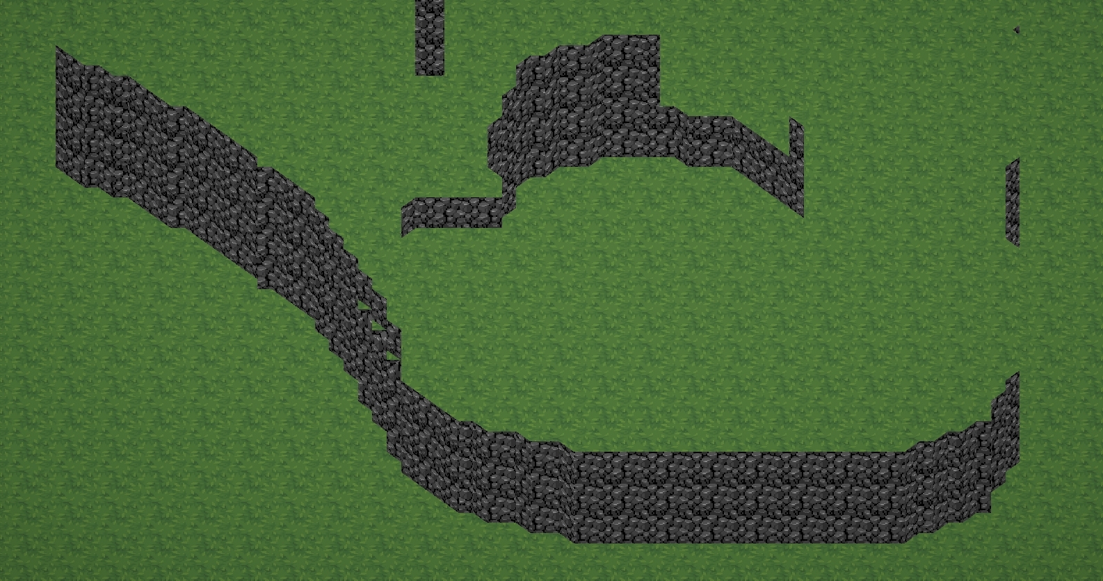
heya, is anyone aware of a way to texture these slopes with a 2d sprite?
alternatively, a way to texture right on top of the slopes (following the border of this plane: https://i.gyazo.com/69b7c1645e8482b65131eb19869f4efe.png)
i've tried a few things, but texturing via worldspace uvs doesn't work as these slopes are at different heights (and therefore the texture tiles differently)

what'd make sense to me is probably making something like an outline where the area that needs the sprite texture is white and everything else is black, but i'm unsure how to orient those sprites to face the correct direction
i would be trying to use this sprite as reference
I don't see exactly what you want to do...
You want to texture the grass in this case?
this might be a more straightforward visual

basically I want to texture the border between grass and mountain with that sprite
but I'm unsure of how to make the texture orient itself to face the edge/corner

(ignore the slopes in this case)
getting it to face the edge of the right here isn't too hard, but then I'd need to figure out how to do it for every other angle there
all the faces with this are slopes?
atm it's just a triplanar shader projecting grass onto the top and cliffs onto the sides fwiw
all slopes should share a texture is what you're saying?
sort of
i can get slopes to share a texture, my issue is more orienting the texture correctly
like how can I have the border face east on the eastern cliffside, f.ex
vs. the south, which is the way it's already facing
the border of the texture?
the more grey part?
I think I'm missing something...
The slopes already seem to be facing the correct direction no?

ah, detecting the edges and changing texture accordingly?
right
hmm, I mean looking for discontinuity in normals and rotating accordingly is probably how you would do it. Actually implementing that though is beyond me...
yeah, i've been trying to look up resources for this but it's surprisingly scarce
Ooh, look at that! A new weapon in #ProjectTerra !
This is the Kama, which can be used in battle, but also as a form of movement for exploration and for puzzles off course!
#gamedev #indiedev #pixelart #ドット絵

i'm trying to replicate an effect like this
oh you know what
i guess i could use the vertex/world height
it'd be a very weird interpretation of the word outline but if the vertex below the current one is 10 meters below, you know the edge has to face south
right, thank you. I did add emission and set it to like 1/3rd the brightness already. It still looks quite off so I guess I'll have to try the low level method haha. I am using URP btw.
I was hoping that flipping normals would somehow do the trick but I guess it's not that easy, I did see quite a few people have an issue with this while making a 2.5D platformer
Another “fix” would be to actually use a 3D model and just protect it orthographically to your camera. This way the shadows are accurate. Using dynamic resolution in the camera you can achieve a pixel art style while reducing the cameras rendering time tenfold
A solution that's useful with sprites is to implement a custom lighting attenuation that ignores normal direction, only being dependent on distance
Although implementing any kind of custom lighting in URP is not as easy as it should be, it's not particularly hard in this case especially if you only need to skip the normal attenuation part of the existing lighting calc for the desired effect
Here are some resources
https://nedmakesgames.medium.com/creating-custom-lighting-in-unitys-shader-graph-with-universal-render-pipeline-5ad442c27276
https://github.com/Cyanilux/URP_ShaderGraphCustomLighting
Yeah, this would honestly be the best approach which is what I do for a project. Create a crude 3D mesh of the sprite silhouette and just use the lighting that's there.
yo, how could i make a Fullscreen shader that would render only the wireframe of 3d objects in the scene?
hi, i have this displacement shader which i think i followed unity's tutorial for
how could i do so the displacement only starts after a certain height?


Is this a bug? My lightshaft shader works fine in the editor, but when running inside my Quest 3 the calculation is off.


I'm using OpenXR, URP.
Weird thing: it works correct for a unity cube primitive, same in both editor and player, but not this hollow cylinder exported as fbx from blender.
the cylinder has baked transforms and is also 1x1x1, samt dimensions as the cube.
Very weird. Using the same cylinder next to a cube primitive, both scaled to double height, it works fine in both editor and player. Could there be an issue with the ceiling mesh (from VR template) giving this problem?

Ok, it was static batching that broke it. Making the light shaft non-static fixed it!
Unity6 Demo Building from Shader Compiler is slow (Use CPU)

Why does it looks like tihs ?

I'm trying to render a mesh using compute buffers, without sending data back to the CPU.
When I try to render the mesh, the number of indices is zero and the mesh doesn't render, but I do get draw calls in the render pipeline.
I previously used Ver and Tri compute buffers to render the mesh using the meshRenderer component and it worked fine, so the problem is probably with the shader.
How can I make it work?
draw call :
shader.Dispatch(0, (res + 2) / 32, (res + 2) / 32, 1);
        Graphics.DrawProcedural(
            material,
            new Bounds(transform.position,transform.lossyScale*10),
            MeshTopology.Triangles, 6*(res + 1) * (res + 1), 1,
            null, property,
            UnityEngine.Rendering.ShadowCastingMode.On,  true, 0
        );
Shader :
Shader"Hidden/VertexColor" {
  SubShader{
    Tags{ "RenderType"="Opaque"}
    Pass{
      Cull Off
      CGPROGRAM
      #include "UnityCG.cginc"
      #pragma vertex vert
      #pragma fragment frag
      StructuredBuffer<int> Tri;
      StructuredBuffer<float3> Ver;
      StructuredBuffer<float4> Col;
      float3 worldPos;
      float4 vert(uint vertex_id : SV_VertexID, out int vertexIndex : TEXCOORD0) : POSITION
      {
          vertexIndex = Tri[vertex_id];
          float3 position = Ver[vertexIndex];
          return mul(UNITY_MATRIX_VP, float4(position, 1));
      }

      fixed4 frag(int vertexIndex : TEXCOORD0) : SV_TARGET
      {
          return Col[vertexIndex];
      }
            ENDCG
              }
          }
      Fallback"Diffuse"
}
https://forum.unity.com/threads/how-to-render-a-sprite-oriented-to-the-edge-of-a-face.1559723/
heya, is anyone aware of a way to do what I've described here? I've been looking for a solution for a few days, but it seems very rare
Unity Forum
Heya! I'm trying to recreate this effect: https://twitter.com/lachsen/status/1346589705052299270/video/1
They're using marching cubes terrain and...

Hey guys, so quick question. I'm making a grass geometry shader for a small game I'm working on. I am brand new to shaders and I have been following this tutorial: https://roystan.net/articles/grass-shader/ I have it working as I want it to. I even combined some tutorials to make it cuttable. The issue I'm having though is I made a scene where the geometry isn't even and the grass is not uniform across it (as you can see in the pic and the middle part is a different material). Just wondering how I can fix it. Any help would be appreciated.

Learn to write a grass shader for Unity engine. Generate grass from an input mesh using a geometry shader, and control the density using tessellation. The blades of grass use a random function for size and angle variation, and cast and receive shadows.
Is there a way to get colored ambient occlusion?
Hey, how do I enable and disable reflections of a standard material (in code)?
i am trying to use shader graph to make my sphere become scabrous but it created slits
how to fix it ?

I want to have a rendertexture, black and white, with the cheapest possible DOF on it, in URP. I haven't managed yet. I've tried normal PP and aren't getting anything, tried an asset which claims to do fast shader based blur (sounds perfect? ) but it doesn't work. I considered writing depth into blue channel or something and using that to mask between a blurred and non blurred image, but I think without adding edge expansion/bleeding (how?) this wouldn't work. Any ideas?
Maybe try skipping the multiplication, and just add it to the position?
Any thoughts on why the outlines don't show up on the unity toon shader?
The UVs don't line up at the seam, and they're uneven towards the poles. Try using 3D perlin noise instead (https://github.com/JimmyCushnie/Noisy-Nodes this is a good one)

GitHub
Adds various noise generation nodes to Unity Shader Graph, including 3D noise nodes. - JimmyCushnie/Noisy-Nodes
Can someone give me some direction on how to offset a specific vertex of a UI sprite? For example the bottom right vertex, instead of all of them.
Would need some way of masking which vertex needs offsetting - i.e. obtain a value of 1 at that vertex and 0 elsewhere. Could perhaps compare against the UV coordinates to do that.
Wouldn't a vector2 with values 1,0 work as a mask? Because it's pointing to the bottom right vertex
As a mask, no. You need the value to vary across vertices for the result to be different. But you would likely use that direction/position (or similar values) to calculate the mask.
For example (uv.x > 0.9 && uv.y < 0.1) ? 1 : 0 may work assuming UV is in 0-1 range.
In shader graph could use Comparison, And and Branch nodes for that.
Probably need to avoid scaling planes / model with consistent vertex density.
But geometry shaders are pretty inefficient too, so you might want to look into alternatives. Maybe using DrawMeshInstancedIndirect or DrawProcedural & compute shaders.
Joyce (MinionsArt) has a neat grass system here - https://www.patreon.com/posts/grass-system-urp-83683483
Hi everyone, I do not understand how to expose grandient color on the editor. is it possibile to expose gradient shader? It seems like you can not check the "exposed" box on shder graph for gradient parameter.
It is not possible. If you only need a gradient of two colours can Lerp. For a few colours, put input coords through Inverse Lerp nodes and use multiple Lerp. e.g. https://www.cyanilux.com/tutorials/intro-to-shader-graph/Lerp3Colours.png

For more complicated gradients, can use a texture and Sample Texture 2D instead.
no thank you, this should be fine! nice solution, thanks!
Omg thanks! Took me a while but it worked like this
I'm using amplify
I'm note used to shader logic so I'm not 100% sure why it worked but it's fine
what if I need a noise between these colors?
I used to have a gradient noise ad sample gradient before
Should be able to add noise to the UV.y (or whatever coordinates you're applying the gradient to) before the Inverse Lerps.
it works, but it seems like it's an "adding" mix between them like a blue and a red made me a green color that is not what i would like to see rather a noise with red and blue
I'd probably look into adjusting the mesh generation code to apply UV coordinates to map a tilemap rather than anything specific in shader.
Can you show the graph

I would do something like :
Noise -> Multiply by a "Strength" float property -> Add to UV -> T input of Lerp
The Inverse Lerp is only needed if you need more than 2 colours in the gradient.
I need more than 2, I just put 2 for testing
I had no idea this guy was here, one of the best resources for shader stuff and made all the modern orthographic related guides
so based
Well should still be similar. I'd alter the coords used in the T inputs. Keep the A/B inputs for "min/max" values for remapping the coords. Though I'm still not completely sure where the green was coming from (Color Border maybe?)
If you're still looking for an answer to this, create a mask using a Smoothstep (or Inverse Lerp and Saturate) on the Y coords (probably in object space). Then multiply it with the displacement (sine output). (A value of 0 in the mask will prevent it moving)
you wouldn’t happen to know any resources for this would you? most of the marching cubes examples i can find say to just use triplanar which led me down this route
but being able to map uvs to simply say where to put each texture at which rotation would be amazing
Yo guys someone help me out , so I installed a different version of UniGLTF and it caused many errors so I reverted back to previous but then I get this error .


Package Version Does not exist in the current context
Thank you! I will look into that!
you need to fix uv parametre in noise node
you are using model's uv coordinates for this node
idk what is your uv for this mesh
but i think it's not something close to uv from 3d space
basically you can get something like this with /0.0f operations, you may also get the same result with wrong normals, try to fix them
Yo can someone help me out, do I need to download again?
This isn't to do with shaders.#🔀┃art-asset-workflow probably fits better. But yes, if you haven't already you should try removing & reinstalling before asking there.
No resources come to mind really. But I'd probably still use positions for UVs (similar to triplanar) but calculated on the C# side.
If you use a texture containing a bunch of tiles layed out horizontally, you can divide the calculated X coord by the tile count. And for each configuration of the marching cube/square you can offset that to select a different part of the texture. That's the general idea at least.
An alternative could be pre-modelling the marching square tileset (can manually apply UVs then)
Oh okay but how do I know the version of that one ? Do I only need to download one time?
Becuz I downloaded before , and the navmesh didn't work and it was some other version
I don't know anything about what you're doing or UniGLTF. You need to ask in a more appropiate channel
Oh okay thanks for Ur time tho
ty, this is kind of what I was thinking- I want to use this for a terrain editor for my mappers, so I need to be able to do it live
but deciding texture based on marching cube configuration sounds like a solution to me
I need to do some testing but I can probably bake that into the vertices and pull from it in the shader
and blend between textures/rotations based on that
Hello guys!
I'm trying to apply a barrel distortion shader to a camera
And it is working
But I would like to quit the black parts that I am not using
I'll show you with a photo

This is the shader that I am ussing:
The Add node is used to compute a vertex output. The Multiply node is used to compute a fragment output.
I have somehow connected a node to both of them.

If I delete a connection, Unity won't let me re-create the connection
But it seems to...work just fine
What's the deal with this?
It's annoying because I want to use the same math in both the vertex and fragment shaders. I guess I can just make a subgraph.
figured out how to do what I was trying, for future reference I'm looping through the triangles post-mesh creation and checking if the tri is:
a. flat
b. neighboring non-flat tris
pretty easy in retrospect

Hi, any idea why there is no srgb/linear option for this imported texture?

Im trying to create a water shader with waves, but instead of waves the entire mesh just moves up and down. I followed the tutorial and it gives me the same preview. It just works weird on objects on my side
Alright figured it out haha
nvm ;w;
aaah thank you ive managed, i was doing that but in the wrong place :D
Does anybody have any tips for reducing shader build times?
Has anyone an idea on why is my shader to working when cull mode is set to front? Main effect here is Fresnel Effect, but it completely stops working in cull mode front after using One minus block on the Frensel Effect


You could do manual shader striping/filtering.
Otherwise try to use as little different shaders, enable shader striping settings, and make sure you have done at least 1 cold build so shaders can be cached
This stuff? https://docs.unity3d.com/Manual/shader-variant-stripping.html
https://docs.unity3d.com/Packages/com.unity.render-pipelines.universal@17.0/manual/shader-stripping.html
Will take a look into it, thanks 👍
Cold builds are nice, but whenever somebody does a shader change it ends up having to spend hours recompiling lol
That's a big shader then :o
I think it's that multiple shaders are sharing the same... subshader? subgroup? Forgot what the name is
Importing the same shader script, and therefore forced to recompile if that changes
Ahhh yeah could be, not sure what is best to do there tbh
from my understanding unity has to completely recompile the subshader for every single shader that uses it, which seems a bit excessive
Hey everyone, how can I change the apparent sss thickness of a plane in shader graph using a texture?
Adjusting the transmission mask or thickness didn't make any difference for me.
Subsurface mask made a difference, but it seems to either mask to fully thick or a predefined thickness.

I'm struggling a bit with the "refract" node in urp, has anyone got some tips?
I'm having trouble with learning shader grqph in hdrp. I just can't work out how to make it do anything at all and none of the tutorials work. Any ideas?
WDYM "I just can't work out how to make it do anything at all" ? Like, setting a color property as albedo doens't work ? ...
The thickness is to controll the transmission effect. Do you want to be able to controll the SSS "radius" ?
Thickness didn't make any difference for me, but perhaps it has to do with my mesh. Yea I would like to control the SSS radius.
So the sss radius is only controller from the diffusion profile, and can not be changed per pixel by a texture.
Alright 👍
I mean that I want to make the black parts transparent
You can use alpha clipping here.
HLSL has a function called clip that discards the pixel if its input is less than zero.
Instead of using return float4(0,0,0,0);, just do clip(-1);
Should I just replace the return line?
Right.
I'm not sure if you need to make any other changes. I haven't written shaders by hand in a little while.
Returning transparent black would require you to make the shader transparent, rather than being opaque
You could make it transparent, but I prefer to avoid transparency if I don't actually need it
An opaque shader is all-or-nothing on each pixel: either it writes to the screen or it does nothing at all
A transparent shader writes to every pixel, but might wind up making no change


Ah, it still needs to return, I guess
You have a compile error in the console.
So return 0,0,0,0 after calling clip

You wouldn't return clip(-1).
I presume you get another error when you try to do that, since it's not a float4
just return float4(0,0,0,0) after calling clip(-1)
yes sir
@warm pulsar
You are just my hero
Yo don't know how grateful I am
I've been looking for the error for three days

I'm trying to understand, if you clip the pixels here, is the distortion being expanded out into the clipped space?
clip prevents a pixel from being drawn entirely.
By using clip, we can eliminate the black borders around the distorted area.
right, so why does the black area matter here if the effect is what's contained in the area
so that the shader draws nothing at all, rather than trying to draw transparent black (which would require a transparent shader, not an opaque shader)
flare didn't want to see it at all
perhaps this will be drawn in front of a computer screen model
and Flare wants to see the model, not black, at the edges
oh, so I guess they want half the camera warpped like that, and half non-distorted?
No. This doesn't get rid of any distorted areas.
All it does is draw nothing outside of the area that shows the image
rather than drawing black
The distortion effect means that the image doesn't fit in a square anymore
It has some gaps on the sides.
Wouldn't the border turn into that effect where the pixel buffers aren't flushed?
so kinda like the edges would have that dragging pixel effect
so in the end you either render something or have a space of unupdated pixels
im just curious what the end result is here
If nothing else drew to those pixels, sure
But there are lots of other shaders drawing to the screen here, including the skybox and the ground
Just because one shader doesn't draw to a pixel doesn't mean that another shader doesn't
You can have a problem if your shader writes to the depth buffer (which indicates that nothing behind that point should render) but doesn't actually draw to the pixel
Then you get a pixel with whatever data happened to be in it from the start
Ah, true, so yeah there would be some parts of the scene undistorted instead the black frame if that's the desired effect of the shader
That's about the only think I can make it do. Anything more than that and I just get a flickering visual mess. I just can't find anything that will teach me that isn't wrong pipeline or just not working.
The fact that the pipeline matters so much is a big problem. All the tutorials are URP and they don't even work in that.
Like all I want to do is makr it do something.
Anything
But all it does is produce garbage.
Thinking of just going to code them because it's probably gonna be easier to find working examples.
I have a shader graph used as material in custom render texture, used as animated light cookie. this works in vulkan but breaks in opengles. is this a known issue or something I'm doing wrong?
Almost everything that you can do with urp shadergraph can be done with hdrp or even build in renderer. Can you show an exemple of a "flickering visual mess" graph and what it look like in scene view ?
Making code shaders in urp or hdrp is not an easy task though ...
Ok, so very weird problem
in-game my water looks like this

but the when im in a build this happens.

idk what the issue is tbh. normal transparent shadergraph. been working fine until today
This is supposed to be a glitterball effect. But it's very weird. And very flickery
It might be, but if it's documented that counts for a lot
Alternatively, just playing about with components:
Alos:


I am having a very weird problem with the StackLit shader graph. I'm sometimes getting big patches of pixels that fail to render at all (so you wind up seeing the skybox behind them). This only happens in the game view; it's fine in the scene view.
I'm using UV1 and UV2 for an effect, and I've noticed that the problem only happens if I'm trying to use a UV map in the vertex shader. In the example above, I'm using UV0. I compute the length of the output from the UV node and multiply that by a frequency value.
I also multiply the time by a move speed value.
If I add these two values together and the "Move Speed" property is a whole number, it works fine. If I use any input other than UVs in the top half of that graph, it works fine.
If I filter out NaNs from either of these values, the issue goes away. Everything works fine. In the graph shown above, connecting either of outputs from the "Branch" nodes to the "Add" node fixes the issue.
This makes no sense -- if there were NaNs present, then surely I'd be seeing the vertices jump all over the place as I enter and exit areas of NaN that got replaced with zeroes! My only guess here is that there's other vertex shade work that's getting broken by a NaN, even if the vertices I can see aren't relevant...? Very confused.
This only happens with a skinned mesh renderer. If I export an identical model without its armature (or just display the skinned mesh with a MeshRenderer), there is no problem.
I am absolutely baffled. I'm going to fix this for now with the NaN filtering, but I really need to figure out why this is happening. I'm cleaning up an example so I can share that.


You'll need to show how you did that "glitterball effect".
From your last video, you have bloom in the scene, that is very visible due to the object having a very high emission?
As for the black screen flicker this is also likely due to bloom if the object/shaders outputs NaN under certain condition it can bleed to the full screen with bloom
yeah, I've had that happen to me a few times before
NaN can wind up eating the entire screen
submitted a bug report for this after simplifying it and reproducing it on my PC. how weird!
Hi! I have been following a tutorial for my first compute shader (shell texturing). What does this error mean and how do I fix it?

I found this online: https://issuetracker.unity3d.com/issues/draw-indirect-argument-buffer-too-small-is-thrown-when-using-an-argument-buffer-of-4-ints
How to reproduce: 1. Open the “2022.3.18f1_DrawProceduralIndirect“ project 2. Open the “SampleScene“ 3. Enter Play mode 4. Observe t...
Does this mean that it's a problem with my Unity version? I am on 2022.3.18f1
Yes, it says the bug was fixed in 2022.3.21f1
I'd be curious to try to have a look if you could share the bug ID
I'm not sure exactly how to show you this properly,. but......

It also says this, but I have no idea what it means. Is it saying the 'power' function is the problem?

Yes, exactly that. The gradient noise ends up outputting negative values, and you can not power negative values. So like written in the error : apply an "abs" node to each of the noises outputs (or after the add nodes) to secure the values to positive
That's also why you can see purple pixels in the previews
I assume that means Absolute because there's no ABS node
yes, absolute, "abs" is the HLSL function for absolute
Thank you. The errors are gone, but I still have a black ball that doesn't do anything rather than a glitter ball
Can you see any other issues with it?
You are outputting the graph in the base color, so this will affect the surface albedo that itself is getting lit byt the scene ambiant and dynamic light sources.
If you were expecting this to act like a fake lighting, you need to connect it to the emission output.
Furthermore, if you are using HDRP, you should also make it go through the emission node with "exposure weight" set to 0
Thank you. It was eventually going to be through the emissions node so I put it there. I can't find "exposure weight" though
Orb is so far the same

Here's my setup, IDK is this was you are expecting though :

That's more than I'm getting tbh
I was expecting this https://www.youtube.com/watch?v=kkOTlvLqu-Y

Tutorial on how to create a Universe Sphere Shader in Unity using Shader Graph.
Unity Version: 2020.3.8f1 (using the URP)
Music used:
Walking in the Sky - Nico Staf
This tutorial is for URP that is a bit more straight-forward when outputing emission. Are you using URP or HDRP ? Like I said, for HDRP you should use the emission node and output, as the basecolor will be capped to the [0-1] range
I tried it in both tbh
Doesn't work in either
URP tutorials are easy to come by, but never work in HDRP, and I've not done much URP
Any ideas why it isn't working in HDRP?
I've just very roughly made that tutorial in URP, and it works, you must be missing something
Like I said, it should work, simply by passing the effect through the emission instead of base color.
Did you do it from my screenshot?
Or from the video?
If the latter, you may be right
From the video. If you want to, send your shadergraph file so I can check ?
Sure
So, I took your shader, assigned it to a sphere in my scene.
I changed the "inner color" property to use HDR color, and increased the intensity to make it more "dramatic" : Is that getting closer to what you'd expect ?

Yeah getting warmer

That's what it's meant to be like
Well, I've further increased the intensity of the color to have more bloom and :

Oh cool!
Where would I do that?

Ah okay thanks!
Hmmm this isn't working still

Even though the material seems to be?
Did you assigne the red preview material to the sphere in the scene or the other one ? Tried setting the intensity even higher ?
The red one
I set it really high & low
It flickers with red dots for a second, then nothing
IN-71651
Also, here's a .unitypackage containing the scene I submitted, if that's easier to use
interestingly, the glitchy areas appear and disappear in waves; the closer the second parameter is to 2, the slower the procession is
It's got to be some floating point hijinks, but I can't figure out exactly what they are
Hi,
I struggle to find some information on material transition in a game level. Correct me if I am wrong on these assumptions on how people achieve it:
- Transition on tiles is just e.g. grass tile -> grass/rock transition tile -> rock tile
- Decal projected on object
- object simply put on top on another object (not technically transition)
- big painted texture maps ??
- Other options????
Bonus question:
How breakdown a tiled material with another material on top of it with bigger scale so player cannot see those repeating tile that much. Example with some cracks. I know I can use other props like some rocks, building, plants, lighting etc. I am just curios if there is other options.

Could someone explain why my vector4 can't connect with the other vector4

The main thing that prevents connections is when you try to mix vertex and fragment contexts
(so you try to mix nodes together that wind up flowing into both the Vertex and Fragment outputs)
I don't see that happening here, though.
This is what the function does

what does DepthFade do?
I just want to lower the waves height closer to the island
That sounds like it might be fragment-only

yeah, you're reading Scene Depth
NOTE: This Node can only be used in the Fragment Shader Stage and it is not guaranteed to work with an opaque material.
hmmm thats fair. Do you maybe know a solution for my issue then?
I am still pretty new to this(like 2 days)
I'm not sure what a good alternative would be here.
You may be able to sample the depth texture manually in a custom function node using SAMPLE_TEXTURE2D_LOD
I don't actually have a water texture. Its just a plane mesh
I'm referring to the camera's depth texture, that's what the Scene Depth node samples.
A custom function using this might work
float rawDepth = SAMPLE_TEXTURE2D_X_LOD(_CameraDepthTexture, sampler_PointClamp, screenPos, 0).r;
float eyeDepth = LinearEyeDepth(rawDepth, _ZBufferParams);
Out = eyeDepth;
Always need to use LOD versions of the sample function when connecting to the vertex stage. (Kinda wish shader graph would just automatically switch to it)
So something like this

How do I access camera's depth texutre?
and what would be the input in the custom function?
Would need to pass a Screen Position (regular mode) into the function for the screenPos
The rest should hopefully work but check if the errors say something is undefined
Do you know why that's the case?
there's so much weird niche information (like that _CameraDepthTexture exists in the first place) that I've been struggling to find

The regular sample functions use the screenspace derivative functions (ddx / ddy) to calculate which mipmap should be sampled. Those are available as the fragment shader runs in 2x2 pixel blocks, hence it only works in the fragment stage, not vertex.
Specifying which mipmap you want with the LOD sample avoids that
ah, that makes sense (although now I'm left wondering why you need to compute the derivative for that!)
I think it's something to do with objects being further away have a greater change in derivatives across pixels, hence need a lower res mipmap. Exactly what calculation is done I'm not sure though, bit beyond my knowledge
Hmm that's a bit annoying. What render pipeline is this for, URP?
Yeah URP
May be able to add #include "Packages/com.unity.render-pipelines.universal/ShaderLibrary/DeclareDepthTexture.hlsl" then
weird its talking about normal render pipeline

nope still nothing
@regal stag Maybe this causing the issue

It's a convenient way to estimate the "density" of the UV coordinates. Where it's more dense, you want lower resolution mip maps so the pixel density of the texture matches the pixel density of the screen as closely as possible. Many things can affect the UV density, like distance, angle, UV tiling. Derivatives handles all of that automatically by comparing the neighbor pixels in the 2x2 cell.
Not sure what you're referring to here
Output Texture but never mind that wasn't it
Has the shader still got an error message?
Yeah still the same error
none of these lines refer to the built-in render pipeline
it's all Core SRP and URP stuff
(and some ShaderGraph code)
I see!
I think adding that include I mentioned to the start of the custom function body should fix it
Uhm how do I do that?
Same where you posted the earlier code here
Might be other errors too. Make sure you add the screenPos input, and rename the output Out

Change the body to
#include "Packages/com.unity.render-pipelines.universal/ShaderLibrary/DeclareDepthTexture.hlsl
float rawDepth = SAMPLE_TEXTURE2D_X_LOD(_CameraDepthTexture, sampler_PointClamp, screenPos, 0).r;
float eyeDepth = LinearEyeDepth(rawDepth, _ZBufferParams);
Out = eyeDepth;
I'm hoping that will force the shader to declare _CameraDepthTexture
Rest looks okay, though may want screenPos to be a Vector2. Add a Screen Position node to the graph to connect to it.
Once working, should be able to copy the nodes you have for your "Depth Fade" subgraph but use this Custom Function instead of the Scene Depth node
Only thing Im worried about
is that everything looks pink now
Yeah its still bitching about _CameraDepthTexture
I can't find anything about it online either

One thing I realized is that the #include dissapears in the generatedShaderCode
Not sure if this is the right way to go about it, but looking for some help with an issue that i think shaders may be able to solve, decently new to unity postprocessing / graphics
If you have a question/problem just ask/explain it. Don't ask to ask.
But if it's post processing related, #💥┃post-processing channel might fit better.
Gotcha, wouldn't know which it is to be honest, looking for a way to not render the lights from a room behind a door in a 2d sidescroller project
Could maybe try using File mode instead of String. Would be something like this (in a .hlsl file)
#include "Packages/com.unity.render-pipelines.universal/ShaderLibrary/DeclareDepthTexture.hlsl

void GetHeight_float(float2 screenPos, out float Out){
  float rawDepth = SAMPLE_TEXTURE2D_X_LOD(_CameraDepthTexture, sampler_PointClamp, screenPos, 0).r;
  float eyeDepth = LinearEyeDepth(rawDepth, _ZBufferParams);
  Out = eyeDepth;
}
scares me how fast you came up with that
dont worry you're not the only one
If you use URP (specifically with 2D Renderer asset) it has a 2d lighting system where you can control the angle I think
https://docs.unity3d.com/Packages/com.unity.render-pipelines.universal@17.0/manual/2d-index.html


I am using URP, will have to mess around to implement your suggestion
was trying to use occlusion areas to just not render it to be honest, wanted it to be essentially black space beyond the door
Could maybe have some black quads/sprites on top that appear when switching between rooms, using C# scripts to toggle their visibility.
current situation is this, have URP 2d lighting system with a shadow caster on the door sprite, if camera moves far enough then you can see the light source in next room despite shadow being cast. gonna give your angle and sprite generation ideas a whirl. thank you!

it's been a while since I've messed with the 2d lighting, are you sure it's not a layering issue?
something else to check for, thank you!
I guess in theory I could just tie its order in the sorting layer to opening the door
idk if there is a "right" way to doing this though typically
dont wanna do the sketchy solution and pay for it further in development
Not too sure why this error is occurring. But I'd try this instead
#ifndef SHADERGRAPH_PREVIEW
#include "Packages/com.unity.render-pipelines.universal/ShaderLibrary/DeclareDepthTexture.hlsl
#endif

void GetHeight_float(float2 screenPos, out float Out){
#ifdef SHADERGRAPH_PREVIEW
  Out = 0;
#else
  float rawDepth = SAMPLE_TEXTURE2D_X_LOD(_CameraDepthTexture, sampler_PointClamp, screenPos, 0).r;
  float eyeDepth = LinearEyeDepth(rawDepth, _ZBufferParams);
  Out = eyeDepth;
#endif
}
oh there's a missing "

Yeah that's really weird, this has nothing to do with lights


can you show a screenshot of the node settings for the custom function?

set "GetHeight" to the function name
That works
yeah
Holy shit
It jsut doesnt work in the sub shader
but thats not the worst
whichever function name you put in the node settings is what function is called from the Source file + whatever precision the node is set to. So you can have multiple functions in one file and only execute which function you want from your custom function node
Aaah
okay that makes sense
Thanks for the help!
Now I just gotta clamp the value ad it should be fixed
https://docs.unity3d.com/Packages/com.unity.shadergraph@6.7/manual/Custom-Function-Node.html
I'd say you can right click the node and "Open Documentation" but for me at least it links to a 404 lol
May want to change the 6.7 to 17.0 in that link for a more up to date version
ah my node is returning 14.0 which was 404'd
nvm it's the rest of the url that was 404'd
I guess they changed the filename
oh, no I see
I think the F1 just checks the node name, but that's something we define for that node
it tries to open the documentation for the node title, which in this case is the custom function
if I'm writing my own custom lighting shader graph(https://blog.unity.com/engine-platform/custom-lighting-in-shader-graph-expanding-your-graphs-in-2019) is there a way to not render cast shadows without disabling them? I'm sampling the shadow map myself to do some customization to how shadows are drawn so if I try to draw my own shadows they are getting drawn twice. If I turn off shadows I can no longer sample them so that's not an option

What do you mean by "they are getting drawn twice".
It also should be possible to sample (receive) shadows from other objects without that one casting a shadow
meaning they are being drawn by default by the shader, and then my custom render of shadows are being drawn on top of that
You'd typically want to use an Unlit graph when doing custom lighting. That would stop the default shading/shadows appearing
Though there are some workarounds needed
Can use the subgraphs from my package https://github.com/Cyanilux/URP_ShaderGraphCustomLighting
Or look at the CustomLighting.hlsl file at least. Need to use the #undef REQUIRES_VERTEX_SHADOW_COORD_INTERPOLATOR to avoid errors in Unlit Graph, and define keywords in the graph.
@regal stag @fair jackal Thanks from you two It is working correctly now!
alright thank you I'll take a look!
think I found a solution to my issue as well, will let yall know if it works. ❤️
So, i'm working on adding hats but i'm curious on if there is a shader that would use a mesh to hide other meshes so for instance a hat goes on the person head but the hair goes through the hat. So I was wondering about using a mesh with a shader that would hide the hair.
https://www.youtube.com/watch?v=z2uFaBoYhaY this technique perhaps?

How to Use Depth Mask to Hide Water in Boats in Unity
1:06 to skip Intro
5:14 to jump to Blender Instructions
Have you been trying to figure out how to put your boats in the water, but not let the water seep in? Then this tutorial is for you!
Here is the Unity Wiki on the depth mask:
http://wiki.unity3d.com/index.php/DepthMask
Last I checked...
only inverted obviously
Yes like that pretty much.
Hey everyone. Dealing with a lots of world space canvases and i needed to disable backface culling.
Found a shader in the forums to do that.
It works great, but those elements can only be seen on the left eye in VR.
I'm a complete beginner when it comes to shaders though.
Could someone help me adjust this code so it works in VR on both eyes? I dont want to change Stereo Rendering Mode for Oculus since it works with default UI shaders too.
I did the steps explained in the docs: https://docs.unity3d.com/Manual/SinglePassInstancing.html
But it didnt have any effect
If possible (but not as urgent), i'd also like to be able to Mask the Ui Images that use Material of this shader.
I appreciate any help.
The code for the shader i used is too long to post here: https://pastebin.com/YLiAieh8
Source: https://forum.unity.com/threads/worldspace-canvas-backface-culling.310857/
Pastebin
Pastebin.com is the number one paste tool since 2002. Pastebin is a website where you can store text online for a set period of time.
Unity Forum
Hello guys,
I have a bunch of worldspace canvases and when i move around my world, I can see the backfaces of my UI. I am using a separate camera for...
I'm using XCode to do in-editor GPU frame debugging on my macbook. The capture works great, but Unity freezes afterwards, and I have to kill it and restart.
The debugger isn't paused -- I can pause and unpause in XCode and nothing happens over on Unity's end.
Has anyone else had this problem before?
I'm discovering that using simplex noise in the fragment shader can get very expensive 🥲
on my macbook, the ALU is parked at 100% utilization, and the fragment shader is doing billions of ALU ops
How can i optimize my scene / remove things as even with this basic room its sending my VR usage from 4.2ms of 11.1ms (In SteamVR) to around 17/11 ms
and taking away on the screen mirroring FPS by nearly 60fps when sat doing nothing 🙂
This is my current Room and theres really not much to it

im assuming my main problem is the ligthint

you can see the GPU usage here once i unhide the room
and it gets worse too
Real-time lighting can be very expensive, yes
You should see how it behaves when you toggle the lights -- or when you turn off shadows, if they're enabled
how can i toggle shadows sorry?
im new
Look at the inspector for your lights.

still burns FPS
with "no shadows"

less of a jump now between Lights on and off
still goes quite high tho for a background ap
The next thing I'd check is how complex these assets are.
You can get a vague idea with the Stats window in the game view -- it will tell you the total number of triangles

uhhh quite high
21.4m
Wait is this not using my GPU?
or is that what "Render Thread" is
the render thread is responsible for setting up work for the gpu
software rendering would be giving you truly catastrophic framerates
and yeah, you have 21 million triangles in this scene
that's a lot
its going from 7.4 (when not in play mode0
to 21.4 when in Play mode
How is 1 Spot like 3million?


MY CHAIR IS 15MILLION
Nahhh wtf
somt broken right there
I believe you get an inflated triangle count because one object can get drawn multiple times.
I know that turning off decals on one of my skinned mesh renderers significantly reduced how much it contributed to the tri count
I'm a bit fuzzy on that.
whats a target for Scenese then of this size its like
4mx6m and just a gaming room
it's hard to give a target; it's just that lower is better
I guess that you could look at what VRChat suggests: it wants your avatar to have under 70k triangles
20 people standing around would therefore be 1.4 million triangles
Yea
i called my brother and asked for how to optimize lighting
We got the FPS to solid 60 and a 5.5ms SteamVR "Performance" thingy
and screen mirrors now 60-90
when playing a game
Thanks for helping me
Hi. I am trying to achieve perspective rendering of 3d characters inside UI. Since our UI uses an ortho camera, my idea was to send in the main cameras projection matrix and worldToCameraMatrix and transforming the verts using those. So to validate the idea I am just doing it on a normal sphere in the scene (using a perspective camera, not UI), and changing out UNITY_MATRIX_V and _P with those values from camera. It works fine when using the values in shader of UNITY_MATRIX_P and my provided camera.worldToCameraMatrix, but using the values of camera.projectionMatrix instead of UNITY_MATRIX_P then i can no longer see the sphere. First of all, is this a valid work around conceptually? And is there some kinda transformation that happens to UNITY_MATRIX_P that isnt being done when I use camera.projectionMatrix?
Can you do that with fog, outside of fog voids?
Like, say, to stop random cars filling with fog?
doing some work for a course but the material looks visually demolished compared to the professor's example. is this a graphics issue on my end or something? I'm hoping it at least appears like the right side on someone else's computer

Ambient light not generated for the scene
ah, definitely must be that then haha
I want to be able to dissolve a piece of geometry.... how to describe it. It's like I want to have thousands of invisible spheres all over the mesh growing and where they are they cut out the geo...
which I'd blend into with distance from a transform
I would want it to be in world space rather than UV space
3d voronoi mabye but not? Is there a node that noisily clusters spheres everywhere? (would be too good to be true)
I don't suppose you can use a VFX graphs' geometry to inform alpha clip on another object
3D voronoi you can get through NoisyNodes (download off Github)
How can I make a compute shader that creates a mesh of an object that is extruded like the "Extrude Along Normals" function in blender? I need this for a shell texturing shader
displace the vertices along their normal vector
world position + nomal vector times multiplier
what Xandi said is the way to go + why compute shader? I'd assume shell texturing would be done in vertex shader no? Also make sure the mesh is smooth shaded in case you don't want the edges to split and leave gaps between the faces
Hey everyone, how do I do refraction in shader graph on an transparen object using HDRP?
RTX 😉🔥
I don't want to use raytracing
The lit shader has a screen-space refraction option, but I don't see how to do it with a custom shader graph
Hello people! One quick question: I want to add an interaction with a snow shader when the player walks on top. I have seen a lot of tutorials that use an extra camera and a render texture to do that... Is this efficient tho? Is it the best way?
What if I have a really big snow plane
I just don't know if it's the only option hahaha
I'm usually bit hesitant to use render textures (with camera) for this type of things due to the overhead of using extra cameras. Compute shader is something that I would definitely consider using to draw those trails on the texture. On larger map the map should probably be divided into chunks and same way there should be one trail texture for each chunk to keep only the relevant areas on the memory at once
Wow, hadn't thought of using Compute Shaders, do you know any examples or info I could use?
I think I found something based on a grass shader
this isn't a tutorial but achieves something similiar to what you are doing: https://www.youtube.com/watch?v=Uy5DUc4Np7E
Interesting! I will look at it
Thank you!!
Tech art is dificult ahaha
probably if you're doing some sort of volumetric fog I'd assume.
https://ameye.dev/notes/rendering-outlines/#blurred-buffer
Can someone help me understand how this was done? I'm so confused.

🖍️ Explaining multiple techniques for rendering outlines and highlights for real-time applications. This includes vertex object-space as well as screen-space methods. This can be used to render outlines in Unity or Unreal. Outlines can be used for gameplay reasons or aesthetics.
Like how do you scale down the render result of a pass?
that seems like post processing effect so you need to do that in some sort of post processing shader. To down scale the pass you have to make either buffer or texture where you store the scaled down texture
I have an enemy damage flash material with appropriate shader graph. Now i want to make an outline around my sprites to indicate something. Is it possible to give a sprite 2 materials? Or should i somehow combine both shader graphs into one? What is the right approach here
Hi, I'm looking for dissolve effect but i don't have the emission on my game like the mats someone know why pls ?

Maybe you need a bloom volume from URP?
dunno not good with shaders
i'm on HDRP and i have Sky and fog volume
maybe its a post processing side ?
im new to shader so x)
i fix it its because of the Sun emission is too high so i didn't see the emission of the shader
So the triplanar node seems to require a Texture 2D but i want to use a procedural texture i have generated in a seperate shader graph, is there a way to combat this or will i have to just make the triplanar mapping from scratch


HDRP uses different intensity units from other render pipelines, so you'll have to crank up the number by a lot to be seen in a bright area
yes i see that
Holy hell, post processing is the worst thing I've ever used in my life.
Never using it again
then you better find solution made by someone else or use outline method that doesn't require post processing
i have made a fairly basic shader graph shader using builtin, but it takes FOREVER to compile. i did some research and i'm guessing it's all these keywords causing variants to be genereated. How do i get rid of these keywords to speed up build time?

I have a question I have found myself confused.
Let’s say I add a normal sphere.
It has 1 material slot element 0.
When I increase to 2, I can add 2 materials(vertex displacement component)
One for the base material and one for a highlight material.
But let’s say I am getting a complex material with multiple materials spread out over a mesh.
Why is adding a 2 material slot creates this highlight effect?
How can I do this with a mesh with more than one material?
Is there a name for what I am doing?
As far as I understand adding more material slots than submeshes causes the mesh to be rendered multiple times with different materials, which you're not meant to do under most circumstances
I think all shading of a mesh should generally occur within one shader/material
So merging the materials into one?
And swap between shaded and non shaded
And add extra slots would likely just choose a random mesh to duplicate in a multiple material object?
Extra slots not associated with any submesh would duplicate the mesh
Or one of the submeshes, not entirely sure how it works in that specific scenario
You can't quite "merge" materials but you can create shaders that support all the necessary features
It's unclear to me what "shaded" and "non-shaded" mean in this context
Sorry, yes merge the URP shaders graph in this case
Ty
I will open my computer and show what I mean with shaded and non shaded later
I'm using shader graph with URP and have just started getting this odd error when connecting new nodes:
_AdditionalLightsPosition: implicit array missing initial value at line 151.
This is an Fullscreen shader type so there should not be anything lighting related, despite the error message. Any ideas? I'm not seeing anyone else that's run into this on the forums
Here's the full error that's logged to the console when I save the shader: https://hastebin.com/share/copivigiru.sql

It appears to be happening on any parent nodes of a custom function node. However I'm still confused because there are plenty other parent nodes that cause no issue

Check the custom function is set up properly (correct inputs, outputs, name). Might also be some syntax errors in it's include file?
It should be fine. It's been working for the last couple weeks and there aren't any errors on the custom function node itself. It was only once I started editing the shader again today that the error started popping up. https://hastebin.com/share/lajokopola.csharp


Hastebin is a free web-based pastebin service for storing and sharing text and code snippets with anyone. Get started now.
Just tried adding a node that already existed and the error shows up. So strange!

Might be that #include line causing conflicts with shadergraph's own "shaderlibrary" used for node previews
I think I got it working by removing the #include and using my own sampler in the ColorSobel_float function instead of the builtin sampler_LinearClamp (idk why I was using that)
The fact that it happened is still a super confusing thing to me since everything seems properly ifdef'd, but some things can remain a mystery 🤷♂️
would this prevent the triplanar node from even being evaluated if the value is not greater than zero?

I dont want to waste gpu time running a triplanar node when its not going to be used

I only use it when the value is greater than 0 because im lerping between 2 triplanar nodes
This works fine but I just want to make sure its not pointlessly actually evaluating it
Probably not. The Branch node uses a ternary operator which in HLSL evaluates both sides. Actual branching may require if statements in custom function nodes.
Afaik branching around textures also requires some special handling, need to use SAMPLE_TEXTURE2D_GRAD and calculate the uv derivatives (using ddx/ddy functions) before the branch. Mentioned here - https://medium.com/@jasonbooth_86226/branching-on-a-gpu-18bfc83694f2
Bro why 😭 😭 💀
graphics programming always doing the most
what if I just lerp the textures before using the triplanar node
then it would only require one triplanar node
well 2, one for normals and one for the actual texture
im just gonna get rid of the branch and leave it be
maybe in the future ill return to this
I do plan on making this terrain material a bit better eventually
but its a material for an entire planet so its a little complicated
actually that means nothing, its the same complexity of any other terrain material
idk why I said that
for now it looks pretty good from space

and pretty good on the ground 

also I appreciate the blit render feature you made and threw on github that supports single pass instanced rendering, im using it for my atmosphere
how can i fix this happening whne i zoom outit like clips out of view i want the Power button visible from some distance


Can someone help me understand this behavior?
I have a custom shader and I had to add the following so that my custom stuff would get masked in the UI:
        Stencil
        {
            Ref [_Stencil]
            Comp [_StencilComp]
            Pass [_StencilOp]
            ReadMask [_StencilReadMask]
            WriteMask [_StencilWriteMask]
        }
however, i am now observing this, basically everytime i load a texture, there is residule textures somewhere in the buffer
I dont know where to look/what to ask for help on, its totally bizarre behavior!
Anyone have a good video to explain how to make textures for my terrain for unity? I have no clue on where to find a video on this. I'm going for a low poly one colored texture.
Hello
I'm having lots of trouble turning on a keyword by code in the editor.
I made a static function that take a material, assign the textures to it, and then turn on some bool keywords, but for some reason the keywords dont change. i'm really stuck i dont know what to do
    [MenuItem("CONTEXT/Material/Set card texture from folder")]
    static void MaterialSet(MenuCommand command)
    {
        Material mat = (Material)command.context;

        Texture2D t = getTextureFromPath(mat, "background");
        t = getTextureFromPath(mat, "holo_mask");
        if (t)
        {

            mat.EnableKeyword(new LocalKeyword(mat.shader, "_HOLO"));
            mat.SetTexture("_HoloMask", t);
        }
        t = getTextureFromPath(mat, "holo_pattern");
        if (t)
        {
            mat.EnableKeyword("_HOLO");
            mat.SetTexture("_HoloPattern", t);
        }
}
i tried two ways of turning it on but no luck.
If i check mat.keywords its missing all of my keywords.
But if i check mat.shader.keywordSpace, there are here
Mornin' all,
Would anyone be able to point me in the right direction for this please? I'm trying to build a Terrain Shader for a spherical world using a heightmap to drive the different texture layers I want to add. (different textures for different heights (grey levels) of the image, but I'm struggling to figure out how to get/set the height from the image.
I've used the node tree attached before to create a 'linear height' shader, but need to adjust/edit it to work with the height map image.

Is the heightmap meant to displace the vertices, or just control the layers?
If you want it to control layers should just need to swap the Position node out here for the Sample Texture 2D
I would check that the values t here aren't just returning null and stopping the EnableKeyword/SetTexture from running. (Add some Debug.Log or whatever)
If you're exposing the keywords to the material inspector as well, there may be some float properties that you should also set, otherwise the Shader GUI might be overriding the values.
Maybe that other canvas with the characters is still rendering behind this one?
Its not null and the texture get set correctly
I'm not sure about "exposing the propeerty"
All i did was create a material and assign the shader to it and they show in the inspector
it looks like its on

do what you say is the material use another float for showing the value in the inspector so it has anotherr name
Generate Material Property is probably what exposes it to the inspector. You only need that if you want to be able to toggle it on the material
May need to view the generated shader code to see what the property name is
i think i found sommeone saying i need to do "mat.SetFloat("_HOLO",1f)
do i do this on top of the enablekeyword or just this ?
Thanks i was hitting my head on walls xD
It worked thanks ❤️ ❤️
So, the layer that is still masking was entirely deleted. the whole game object with that canvas is gone. So I am really confused why its still masking my UI element
I guess the stencil buffer isn't being cleared then. Though not entirely sure how to force that. How is the UI rendered, second camera perhaps?
Also what render pipeline is this
Im instatiating a new prefab ontop of the current page ( and then closing it )
so no new camera or anything like that
and I think(?) its URP?

fp means "fragment program" in this context, i.e. pixel shader. You'll also see vp for "vertex program".
It's reporting the number of variants for each shader. Fragment shaders often have more variants than vertex shaders.
aah, oki, ty
Is there a way to see what all the different features it's compiling variants for are? I tried putting on logging, but I don't see what's actually causing all the variants there
like, surely 5 minutes to compile a single shader is too long lol

oh

Hello, since I switched to URP I cannot set the [Range] and [Color] attributes in the material properties when writing a custom shader. It throws a parsing Error "unexpected TVAL_ID". Does anybody know what happened to those attributes? Is there an alternative?
Range and Color are property types, not attributes. e.g.
_ExampleName ("Float with range", Range(0.0, 1.0)) = 0.5
_ExampleName("Example color", Color) = (.25, .5, .5, 1)
My bad on the terminology. I copied the example straight from the unity Shaderlab docs. I'm getting a parse error
Bit weird then. Could maybe have a fullscreen quad using a shader with
Stencil {
Ref 0
Comp Always
Pass Replace
}
To reset the buffer. But shouldn't really be needed. URP usually clears the camera buffers every frame. 🤷
May just need to double check the syntax of all properties. No extra brackets.
Also make sure your texture ones have that extra {} at the end - that's something missed quite often. (And iirc that only errors when other properties are put next to it?)
it was those extra brackets on my texture :/ thank you Cyan.
so this almost works
the buffer indeed clears, but now its entirely empty

what would reseting the buffer to full look like? im not too good at shader code, but can I invert this?
Would probably need to adjust the render queue so it renders either before or after everything else
Question on Stencil buffers and overlapping. For optimization reasaons, im trying to limit the amount of unique layers. I am using a box surrounding an interior space, where you can only see the inside of the space via a threshold. The outerbox has a stencil shader on it set to equal, so it masks out the geometry its around. this works perfectly as i would like, however when you enter a space, you can see the other stencil boxes from inside because the stencils are overlapping. Any insight on how to use a single stencil layer in this fashion, where when you are inside the other same layers arent composited on it? Seems like it needs to be something with depth or sorting order?

Can anyone explain why my noise texture will have random colors on the edge and not white?
The first image is using "Noise Texture".
The second image is using "Simple Noise Node".


Likely some precision differences with the colour channels due to how textures are stored/compressed. If it's a greyscale noise texture, just use one of the float outputs on the sample texture node (R, G or B) rather than the RGBA.
How to do that, its a bit too late to make drastic changes. Even once a use the step node on the "Noise Texture", it already have RGB colors. So i think it might be the texture being the problem, as shown above.
Shouldn't be that big of a change. Use the R (or G, or B) output from the Sample Texture 2D node instead of RGBA.
Importing the texture as Single Channel may also fix it, not sure
Y'know @deep moth, I find it very interesting how similar the effect caused by the posterization looks to the function in a graph


Is there any way to get the per-instance index in inline raytracing in a compute shader? Like I need to know which instance I am looking at so I can properly get its transform from a buffer
Haha yeah that rocks. Feels like a neo in the matrix moment when u get a feel for the way functions make pictures.
I'll bet you could smooth it out if you got clever with a smoothstep function!
something more like this

Hello! I have the following bit of code to produce a smoothed out circle:
    _Size,
    _Size - 0.1,
    length(uv - _Position)
);```

**_Size** and **_Position** are in UV Space.

Now, i'd like to specify the size of the circle in world space dimensions (meters).
How would I go about this?Hello! I am relatively new to Unity. I was trying to use lilToon to achieve semi-transparent stencils, but despite following the docs it doesn't seem to be working. It may be because I messed up something in duplicating materials, as I wasn't really sure how to do it properly.


ah, nevermind! i solved the issue on my own

Does 3d TMP text not sample depth? Making a card game with 3d cards that overlap, can't seem to find a fix anywhere for this
https://i.gyazo.com/f456ad32f79de2452e4f947a06215828.mp4
i am making a shader using shader graph the builtin pipeline and the unlit shader as a basel. For some reason, in game (vrchat) the shader is being rendered at an offsett on the right eye. does anyone know what could be causing this problem?

i created a simple shader that makes the surface of a plane wavy using noise
however the wavy surface is not visible even though the shader is set to lit
how can I make unity recalculate lighting?
I think I have to somehow update the normals as well right?

Eaxctly, you are only displacing the vertices position, without affecting the normals, so light calculation is still done like if it was a flat plane.
There is no way to automatically recalculate the normals after displacement (unless using shader code and geometry shader ...), so you have to do it yourself in the vertex function.
If the noise that you are using also outputs derivatives in addition to the noise value, you can use them to calculate the normals, else you can sample the noise 2 more times for each vertices (with a X and Y offset) to calculate the derivatives yourself and build the normals.
is there any reason why you have to make it wavy using shader?
if you do it from script (c#) there's Mesh.RecalculateNormal function
I added this shader to a material an used this material inside of an image. Why doesn't the texture get shown as the image

How can i make this material not react to the lighting in the scene? the purple makes it unusable

Choose an unlit shader
thanks 🙂
anyone have a object specific pixel material
is there something im doing wrong? it isnt working.

its a shader graph and im trying to put a cubemap onto it
anyone able to see whats wrong?
nvm figured it out
Could someone kindly provide guidance on procedurally generating a canvas UI-based repetitive shader - Graph without the utilization of any textures?

Hi!! This sounds like a cool problem. I'll bet you could get a good start at it by using 2d distance functions for shapes and domain repetition techniques in the uvs.
Here are some resources that are geared to glsl but very informative in terms of technique / concept and pretty easy to transcribe if you have experience with written shaders.
For understanding making shapes with shaders:
https://thebookofshaders.com/07/
For understanding how to repeat those shapes:
https://iquilezles.org/articles/sdfrepetition/

The Book of Shaders
Gentle step-by-step guide through the abstract and complex universe of Fragment Shaders.
Articles on computer graphics, math and art
I apply this shader on an Image. I'm only seeing a grey to white square that fadedes like the texture should do. Why doesn't the image get rendered?


How slow are Shader Graph shaders vs normal ones.
Like I know it depends quite massively on exactly what the shader is doing, but should you expect a pretty big performance drop regardless?
Also, if let's say you had 1000 quads stacked on top of each other (slightly varying z) and pointing at the camera.
If these quads are opaque, I assume the renderer doesn't try to render all 1000. It knows which frags will be representing which quad.
So it's only the vertex func that'll be ran for all, I assume.
With transparent quads though, even if the alpha is max, will it render all the quads fully?
Yes, if depth, prepass is enabled, only the top most will be rendered and if not, some of the fragments can still be skipped by chance if something is already drawn in front of it (closer to the camera). Transparent geometry on the other hand must always be rendered (if not behind opaque geometry) even behind other transparent geometry (theoretically it could be possible to write to depth buffer only if the alpha is 1 but I don't think that's easily possible in unity). That is exactly the reason many games suffer with performance when you go inside smoke grenades because the smokes are usually rendered as multiple large transparent quads/particles
Hmm. Awkward considering I need to render ~200 small transparent sprite creatures 😛
when it comes to 2d rendering, I know very little but 200 doesn't sound too bad especially assuming those are not covering large proportion of the screen at once (if you are inside a smoke grenade, there might be dozens of smoke particles covering the whole screen at once making it really expensive). Sprite rendering is usually also very cheap (simple fragment shader)
I'm doing some (relatively simple) custom lighting on them, and did a stress test. My Laptop isn't amazing, but with 200 on screen I'm hitting around 40 FPS in build.
Checked the profiler and it's mostly from Rendering.
Custom Lighting is definitely doing it. I swapped to unlit and hit 60 easy even with 400 units.
could very well be but if you have many of the same creatures rendered at once, the problem could also be the lack of proper instancing which your handwritten shader code might not take into account making it impossible for the renderer to GPU instance them together
I'm actually using shader graph.
And ya, I imagine there is quite a few things I can do to improve performance. I'm pretty sure the custom lighting node I found is calculating specular highlights and then doing absolutely nothing with it.
make sure GPU instancing is enabled for the material, there should be a checkbox for that
I did but I got some strange lighting behaviour.
I'll look at it again toomorrow, it's pretty late for me.
Mind if I toss you a ping if I find anything?
feel free
thanks
"Could you Guy's kindly provide step-by-step guidance on achieving a repetitive canvas UI shader without relying on textures using SHADER GRAPH ? Your assistance in this matter would be immensely beneficial for my learning journey."
Afternoon all, Yep, I'm struggling again. lol.
I'm trying to add displacement to an irregular shaped object using Shader Graph (URP), but struggling with grabbing the object normals and displacing from those instead of the origin. Any pointers please?
Position + Normal * displacementAmount no?
I shall give it a go. Thanks 🙂
Hmm. Okay, soooo, obviously doing something wrong I think. lol.


A haaa, nm, fixed it 🙂
Okay, next question. Is it possible to update a Mesh Collider based on the object displaced by the shader? (the displacement/update only happens on start, so no worry about performance etc)
I think you could break it down into (1) separate blocks (there, of uniform length), which in turn you can split into (2) a header and body; the header (circle for pfp and then three rectangles) is the same, and then the body switches between one version with an image and one without
Hi! How do I update from lit to simple lit shader? I heard that simple lit works faster for mobile?
The CPU side deals with the colliders and the shader displacement only exists on the GPU side; the latter doesn't communicate to the former so you can't update the colliders based on what the shader's doing. Rather than using a shader, modify the mesh in C# and update the collider there.
Click on the material in your assets, and then in the inspector, switch the shader (near the top) to simple lit
Yeah I've just modified the base mesh externally with the displacement. It's increased the Poly count some, but meh. lol.
Thanks!
shouldn't matter that much but i'm just curious why does that increase the poly count? if you don't create new geometry, neither triangle nor vertex count should increase or decrease
I've done it on the actual model, not through code and I needed the extra geometry to get the needed level of detail.
ah ok. btw if you are using blender, you can use geometry nodes to proceurally change the mesh in really similar way to how you would do with vertex shader
Yeah I don't use Blender. Hate the thing. lol.
Anyone knows any shader or script that I can use for a free form deformation on a camera?
how can i make dithered shadows similar to tiny combat arena? (in shader graph)
couldn't find the dithered shadow example you are talking about but you could use preprosessors inside a custom function node to output whether you are inside the shadow pass to do something different in there. It would look something like this: #if SHADERPASS == SHADERPASS_SHADOWCASTER
its not very visible in this image but kinda like this is what i mean

oh, that won't be achieved by modifying the shadow pass rendering. In order to achieve that, you would need to modify the shader for the object receiving the shadow. In given image, it would be the ground below. I'm sorry but I have no clue how you would be able to achieve that in shader graph, not with supported features atleast. You would have to do some magic with the custom function nodes if possible at all
I dont playaround with shadergraph much, but this might be useful on creating custom function for the shadow
https://blog.unity.com/engine-platform/custom-lighting-in-shader-graph-expanding-your-graphs-in-2019
Idrk where else to put this
so I have a glasses model right? but the lens are not transparent. is there any way I can make the lens transparent and not the rims?
#🔀┃art-asset-workflow
You can use the base map alpha channel to determine transparency
But to avoid sorting issues you'll want to separate the lenses from the frame to their own material slot so one material is transparent and one is opaque
I'm creating a 2D game with built in render pipeline. How to achieve glow/bloom effect for flame or laser beam?
I don't want any post processing. I want to apply the bloom to specific objects, not to the whole screen.
You could use particles with an additive material over the glowy object to fake it
Could also use procedural geometry to shape the fake glow around the object precisely, but that's often overkill
I have added a blur texture to the existing laser beam shader, BloomColor property with [HDR] PropFlag. Multiplied bloom sampled texture with the color. To output color I added result of the bloom.
This I will use to flame effect
Thanks

Hey, I'm currently writing a really simple transparent vertex-lit shader that lit said material with ambient light, though I'm encountering this one issue: the transparent/alpha part also seems to be affected and gets changed to a semi-transparent white instead. I'm assuming it comes from the Blend part? as the unlit version doesn't have this issue, but still can't get my grasp on (rookie mistake!)
For a few clarifications: I'm using an old version of unity thus don't have access to shader graph. I tried to write said shader the most simplistic way as target hardware uses very limited fragment functions.
I'm not too familiar with the legacy/"fixed function" style of writing shaders but the problem is likely the Blend DstColor SrcColor as that is ignoring the alpha channel for that pass.
I'd probably combine the passes into one as that will be cheaper, and keep using Blend SrcAlpha OneMinusSrcAlpha for transparency.
Also side note, may also want to avoid using a red cross symbol. Might cause legal issues even with the additional triangles here, better to use alternate colours or "H"/heart symbols, etc.
main pewview is not showing preview
This is my first thought aswell, though, switching any Blend color with alpha (or just omitting the line) will result in an entirely white and textureless material
About the single pass, unless I'm doing wrong, it makes the shader unsuitable and with a bit of search on my end, it has to be separated? unsure.
(No worries about the red cross, this is a strictly personal project I do on my free time for education purpose, and have no intention of releasing it  )
)

Based on docs seems like this should work
Blend SrcAlpha OneMinusSrcAlpha
Pass {
  Material {
    Diffuse (1,1,1,1)
    Ambient (1,1,1,1)
  }
  Lighting On
  SetTexture [_MainTex] {
    Combine texture * primary
  }
}
Oh, this works! ...It was all down to how I sorted things in a single pass. Order does be tricky
Thank you for the answers!
I think it's sometimes bugged. But I'd recommend just saving the graph (button in top left) and previewing in scene view anyway
If using URP, can get shadows using the Main Light Shadows node in my custom lighting package - https://github.com/Cyanilux/URP_ShaderGraphCustomLighting
Should be able to use that to mask the Dither node (or some dither texture sampled in screenspace). Not sure on the exact setup off the top of my head though
okay thank you
I am like 80% sure you cant have that symbol. It definitly looks similar to the red cross and you will probably get a cease and desist lawsuit sooner or later.
basically this
I'm aware of it, thanks for the heads up though
So something like this in shadergraph?

This appears to mix the posterization with the original image.
If I set step count to 1 it looks like this.

This is how it looks with 64 steps.

It appears to be mixing pre image with posterized
This is how it looks normally

Oh wait, I get it
Its smoothly transitioning between each step.
yeah!! I dont know if its useful or not just thought it might b fun to play with
something i didn't make clear is that you can adjust the smoothness in that equation too


URP, I need help on building a shader that support multiple alpha objects, my friend modeled on blender a set of different flower and trees as billboards and then exported the whole group as a single object sharing one material. I tried building a simple shader on unity with transparecy in it but I get a very weird effect where far elements gets rendered on top of the nearest. Can somebody help me fix that?

sorting order issues are really tricky! One very simple way to solve the problem would be to use a cutout shader instead of a transparent blend shader.
So they're technically opaque but discard the pixels that are below a certain alpha threshold
beyond that solutions tend to get pretty technical and are hard to solve w/ shaders alone in my experience.
Order-independent transparency (OIT) is a class of techniques in rasterisational computer graphics for rendering transparency in a 3D scene, which do not require rendering geometry in sorted order for alpha compositing.
This is the domain of solutions for this problem ^^
easiest is just to use dithering with alpha discards -- cutouts
Anyone know if its possible to rotate an individual tiles on a tilemap using a vertex shader? My attempts so far have only rotated the entire tilemap. I'm trying to make the individual tiles react to external stimulus and the effect would essentially be to rotate the tileObject.
I'd be fine with a fragment shader as well. - thanks
Hi Guys,How to make it that over normal character/terrain texture you add just one layer of highlight on the edge of the object, like they did in this new game No Rest for The Wicked.
It looks like just one layer of toonshader, without overwriting the texture. But it's actually not so smooth as toon shader - looks like real (maybe too strong) highlight.
How to do that? 🙂

fresnel (or normal dot lightDir)
Will google that. Thank you very much!
so i made a shader graph that allows me to put on cubemaps, but when i put it on objects, it doesnt line up. is anyone able to help with it?

Did you wrongly order the faces in you cubemap ? 😅
How can I 'preset' shader sampler?
 sampler2D _GlobalMap;```
The global map is set to a rendertexture using Shader.SetGlobalTexture at runtime, which is running fine (atm).
But the problem is, during editing, it's become grey texture, which is hindering the editing process. I want to set it to black during editing so it become transparentOh, I forgot to add, I'm using fragment shader
Global textures always default to grey afaik. If you can make it a local (property) it can default to "black", otherwise you may need to add a keyword and #ifdef around when you sample it.
Hey everyone,
I'm in need of some assistance. If anyone could guide me in the right direction or already knows how to handle this situation, I would greatly appreciate it. I'm attempting to render elements only when they're viewed through another object. In the example below, the cube should only be rendered when viewed through the door. I'm encountering significant difficulties in achieving this. Most tutorials and online resources I've found are geared towards URP, but I'm working on an HDRP project, which seems to have significant differences. Any help would be greatly appreciated. Thanks!
From what I've seen, there doesn't seem to be any way of filtering the opaque layer masks in HDRP settings. If you believe there is any other method besides stencils that I could try, please let me know. I've done some more digging, and I believe the way to go in HDRP is by using a "Custom Pass Volume," but I might be mistaken.

You're right, to do this you'll need to use custom passes and the stencil buffer
I see...
I currently work around it by adding ExecuteInEditMode to the script which calling Shader.SetGlobalTexture
Thanks 👍
Hello!
Do you think i can archive a shine like this via a decal shader?
i want to project a decal on the ground and add the shine in the same shader without any additional geometry.
Is this possible?

Thanks for confirming! Custom Pass Volumes sound like the right track. Where exactly does the stencil buffer come into play with Custom Pass Volumes? Is it handled in the shader or through scripting? I assume I need to write custom shaders or scripts to achieve this effect? I haven't found any HDRP examples for a stencil scenario. Maybe you know of any resources or a similar workflow example? Thanks again for your help! I apologize for the barrage of questions, but I'm fairly new to HDRP and would greatly appreciate any additional guidance or resources you could point me towards.
Hey, did I do anything wrong while making this shader? I'm new to the shadergraph. (It's an 8k screenshot, so that everything is readable)

Check out the "draw renderers" custom pass , in there you have a toggle to "overwrite stencil".
This will allow you to tweak the stencil operation for the objects being drawn in this pass.
To make your effect work, you need to have a first pass that renders the "portal" plane in the stencil as a mask, and the render the objects behind the portal, while checking the stencil value.
Probably works... but you can just put the texture channels into the input ports on the Enum Keywords, then you don't need the Comparsion, Branch and Add nodes
I'm also not really sure about being able to choose the channel anyway. Seems like unnecessary shader variants imo. Might be better to author textures with consistent channels. (I guess that's the point of this over the URP/Lit though?)
You also have an emission map & color but haven't used those yet btw
Thanks, I didn't know that that was possible. Also I have two asset packs that use I converted from Unreal that use two different channel mappings. So thats why I added the option to configure the channels. And yeah I forgot to add the emission stuff, I'm gonna do that now.
I made the shader to reduce the memory load by loading less textures and combining the metallic map, roughness and occlusion into one texture and seperating the channels.
Decals only project on surfaces afaik. You could maybe do a shader on a cylinder mesh that reconstructs the world pos (same kind of calculations as a decal), but the circular part at the bottom will be confined to that mesh (not stick out a little, like it does in your screenshot). I'd probably just use a separate cylinder for the shine.
And to also make it easier for me to use those converted assets. I don't want to manually split channels, save them as images and assign them.
Oh right makes sense, I forgot the URP/Lit has them separate
iirc when importing textures (in Unity's Inspector) you can swizzle the channels (maybe 2022+ though? Can't remember the version it was added)
Yeah it's under the advanced part

I'm using 2021.3.21f (Because of AppSW) and it doesn't show up for me

Ah okay, must be a 2022 thing then. Guess stick to the shader method 😅
Yeah it's good pratice too
ages ago, I was playing beton brutal and noticed that although plants faded out when you got near, they had a dither effect instead of fading out smoothly
now I think about it in this context, that was probably a solution to that problem
each individual pixel is still opaque or completely transparent, but the overall effect approximates partial transparency
Using the Unity Toon Shader, why does my model blow out as blinding white light in the scene view with the post processing if the rotation of Y is set to 0?

Maybe it causes a divide by zero in the shader somewhere (adding a saturate(x) may fix it)
Ahh, that make sense. I can just make sure it's never 0. Be easier than trying to debug it forever. It looks really nice other than that little bug.

yeah, but i want to make sure, that the teleportpoint will be visible on every surface, thats why i want to use a decal.
I could add a cylinder to the decal projectror maybe, so the decal makes sure the ring is projected on the ground correctly and the cylinder provides the shiny effect 
Is there a way in shader graph (HDRP) to make less transparent objects behind more transparent objects visible?
To be more specific I have a cube with an alpha of 0.4 and inside there is another cube with an alpha of 0.9 and I can't see it from outside
I've created two render passes, one for each layer (portal and inside), and regardless of the changes I make in the Stencil Override settings, nothing seems to happen. My thought was that there were no declarations for the meshes' stencil references. So, I devised a simple shader code to assign them a specific reference. However, in this case, neither of them renders anymore, regardless of what I try to change in the custom pass settings.
Do I even need this shader code, or am I missing something completely different? Once again, sorry, and thank you for your help. I'm struggling to understand how to make the stencil and the passes work together from the documentation alone.
Shader "HDRP/Custom/StencilMask"
{
  Properties
  {
    [IntRange] _StencilID ("Stencil ID", Range(0, 255)) = 0
  }

  SubShader
  {
    Tags { "RenderType"="Opaque" "Queue"="Geometry-1" "RenderPipeline" = "HDRenderPipeline"}

    Pass
    {
      Blend Zero One
      ZWrite Off

      Stencil
      {
        Ref [_StencilID]
        Comp Always
        Pass Replace
      }
    }
  }
}
Why decals are okay but additional geometry isn't? Usually the latter is cheaper, I think
latter?
Usually some geometry is cheaper than decal projectors, I mean
ah yeah. i just want to use the projector to make sure, its always displayed perfectly on the ground, no matter what ^^
Hello everyone, is it possible to use any node similar to "Sample Texture 2D" that will sample a RenderTexture?
I am trying to write a compute shader that outputs into a texture, which is then sampled in a Shader Graph and used later on.
If there is any other way, like sending a texture reference to the CS and directly editing the texture, I am open to hearing options. Thanks!
Decals are flat, but the cylindrical effect there is not flat so I'm not sure how you intend to bend a decal projector to that purpose
Honestly not sure-
Ill make a duplicate and see if it fixes it when i do that
You still pass render textures into shader/material using a Texture2D property and Sample Texture 2D
Really? Well then it's weird that it doesn't work
Because from the preview, my RenderTexture is same as the Texture2D 👀
so i cant change the sides-
I’m not sure which category this goes in but when I changed me build settings to android these white dots appeared, why and how do I get rid of them?

This has never happened before for me but now it’s doing it
Ok so I think it’s with the textures
They also have the dots

Can someone please help I’m so lost
I went back to windows and now it’s fixed but I need it in android

everytime i add a new object i have to assign them everytime ,or else it stacks up like on the left

the default output particle quad has a uv mode option and when i use my own shader graph the option disappears


do i have to basically make a shader graph that accounts for the flipbook uv?
Probably yea. There's a Flipbook node which should help
hmm okay gotcha
another question, do you know how i would go about making a drop down option for single texture uv and a flipbook for a shader if i wanted to
Anyone know how to make stencil only work if they are in front of the object depth wise? I don't want stencils behind an object to reveal things on the stencil layers.
Seems possible in 2023.3 (aka 6000) using keywords, but not sure about other versions
https://portal.productboard.com/unity/1-unity-platform-rendering-visual-effects/c/2282-shader-graph-keyword-support
thank you
Render the stencils with regular ztesting (ZTest LEqual) after other objects (then render the stencil-reveal objects). I think that should work
i managed it to get it working but now this is happening
actually
it might not be the best idea to use a distortion effect with a flipbook effect
i feel like the other textures might bleed in
Hi, is there any way of having two separated shaders into the same object?
you can have more than one materials on one object if that what you mean
and can it be activated and desactivated by code?
You can deactivate the renderer or the gameobject, but I dont think you can deactivate materials
What are you trying to do?
Hi, I have this texture that looks normal in the sprite editor/when applied to the object but when I try to sample it in the shader graph it's completely off.
What could be causing this?


I tried restarting, reimporting etc. but none of that works.
i have one shader with an outline and a lava shader onto one object, and another shader that tints the same object green or red depending on the situation so i wanted to put both shaders onto the same object and when the tint goes off just deactivate it
🤔 Maybe you should combine the outlined lava shader with the tinting shader.
iirc, tinting can be emission and you can parameterize the tinting color.
That way you can set the tint to any color you like and turn it off by setting it to black
Question, why can I just plug the output of the final multiply into the clamp node and use that as alpha(pic 1) but I have to multiply the alpha of the main tex with the final multiply before clamping and using as alpha(pic 2).
This is kinda confusing because I am already multiplying rgbA output of the main tex with the base color which is then included in the final multiply.


because you're feeding a Vector (4) into a Float (1) field, which takes the first value, x/R
that makes sense and also explains a weird thing I had going on, thanks!
(And you want w/A, so you'll need to split it off to handle it individually)
it doesnt allow me to reorder them...
I'll try that, thanks for the reply!
Stencil Mask HDRP

If anyone has insights about Render passes and stencil masks in HDRP, please join the discussion in the thread above. Your input would be greatly appreciated. Thank you so much!
If you can edit the asset, you just have to move the faces around on the texture to follow one of these conventions : https://docs.unity3d.com/uploads/Textures/CubeLayout6Faces1.png
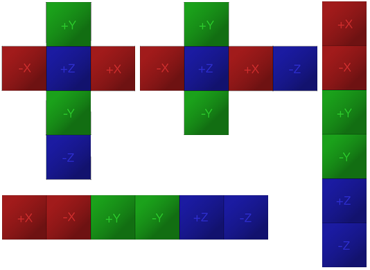
what do you mean texture???
Well, hum, where does your cubemap come from ?
i got it from the asset store
Hi! I have been trying to reduce the android build size and to also speed up my android build (super slow currently). Shaders is the biggest part of the build. Do you know if I need all these shaders for default URP. I am not even sure which are required, and which are not:

Hello, I have created a wave shader which modify the textures uv, is there any way to make it ignore the parts of the texture that is transparent?

the texture looks like this and i only want the effect to be applied to the non transparent part of it
Do you mean the alpha channel should stay still and kind of "mask" the waving on the color channels?
yes the alpha channel should not be affect by the wave, only the color channels
the alpha should basically be ignored completely
Sample the texture before modifying the UVs as well, and then use the alpha from that sample?
sounds like it could work. im still very new to shaders, how would you combine them afterwards?
Is it possible to create a custom shader for an HDR? I want it to be able to also be rotated on the vertical and not just on horizontal
shader for HDR? what does that even mean? sure you can output color values out of the 0-1 range if that's what you mean. when it comes to the rotation, I'm having hard time trying to figure out what you mean
Hdr meant as skybox, default one doesnt have that much control

how do I get the max Y value of an object in world space compare to its origin in shadergraph
for example I wanna get the number 6.5 (height of the object) in this case

but I want to apply the shader to everything, and it would be a pain to manually set it up from every object
oh, I think those are usually referred to as HDRi's. Isn't the panoramic skybox shader meant for "HDRi" no? If you want to add support for more rotations, I'd suggest taking the shader code and modifying it to your needs and not try to do that from scratch https://github.com/TwoTailsGames/Unity-Built-in-Shaders/blob/master/DefaultResourcesExtra/Skybox-Panoramic.shader
is it possible to make it via shadergraph?
I don't see a reason why it wouldn't but it may be hard to replicate all that math in shader graph. you could use Custom Function Nodes to reuse the written shader code to make it easier tho
Hello! Is there any way to get the object current rotation and scale inside a URP Shader?
If you're in 2022.2 there should be World Bounds Max in the Object node that can do this
Basically I want to apply a texture decal inside a shader that points to the forward vector of the model (player)
There's a scale in the Object node, but shaders don't typically use rotations exactly. They handle rotation & scale using transformation matrices.
Like projected from the forward vector, or a different axis but a specific side is aligned to forward?
Mhh projected from the forward vector, basically the texture that the player leaves to the ground must point towards the forward vector
If that makes any sense
It's like a dash effect
Sort of a trail that you leave behind
float cosAngle = cos(_RandomRotation);
float sinAngle = sin(_RandomRotation);
                //Map the UVs within the PainterPosition space
float2 newUVs = (_PainterPosition.xz - i.worldPos.xz)*0.3;
                //Rotate in 2D coordinates. Reference 3D Math Primer ebook
newUVs = float2(
   newUVs.x * cosAngle - newUVs.y * sinAngle,
   newUVs.x * sinAngle + newUVs.y * cosAngle
);
                //Offset the UVs
float4 texMask = tex2D(_MaskTex,newUVs+0.5);
I have this right now
I don't know how to get the "RandomRotation" , which rn is just a random number between 0 and 360, to get the angle from the Forward Vector
You should probably calculate that in C# when you dash and pass it into a material property
Oh, okay! I thought I could do that with matrices
Thanks! This worked btw!
i dont know where this would go but when i changed my build settings to android this happened to my texture, why and how do i get rid of it?

Can someone please help me I’m really confused
I’m using URP to make a Mod for a game and I need to make a shader graph that raises lowlights to make a night vision effect. I’m not versed at all in shaders or shader graphs so if someone could help or tell me how to make a shader graph to do that, that would be a HUGE help because im completely lost
so i found out the cubemap i was using was a single image not multiple images
so i do not know if i can reorder it
you could sample the opaque texture, do some transformation on it which raises most of it (e.g. multiply by a big number and saturate, or take some small power) and then return that
while some real night vision works by multiplicating incoming light by a large number, this wont work on totally pitch black environment, zero light value multiplied by anything will still zero (black). You can actually 'cheat' it a bit by adding a light source near/on camera, then use postprocessing for the green effect and vignetting.
I'm not sure what is causing it 🤔
show you texture import setting and the texture preview.
check you lightmapping setting, and clear the light map if it's baking/baked
maybe it's lightmap still in process of baking
Question, does unity_worldtoobject matrix work on spriterenderer?
I tested it on meshrenderer and itworks, but not on spriterenderer
I'm havins issues to make a skybox from shadergraph starting with this hdr, can somebody please help?

There are several cubemap layouts
https://docs.unity3d.com/Manual/class-Cubemap.html
If yours is just one image it might be "latlong" or "spheremap"
nah it says cubemap but it appears as a sphere icon
"A sphere icon"?
You might be looking at a material asset rather than the texture import settings

In URP 2023+ sprites seem to use the SRP Batcher now (during play mode at least). So it may work there. But other versions and during edit mode, sprites are dynamically batched (that combines meshes / vertices already in world space, model matrix is cleared to identity, likely inverse too)
You can open the image in an image editor (photoshop, gimp, paint.net ...) and move the zones around to match one of the layouts
yeah i cant do that im way too stupid-
is there a way to do this though?

how should I consider mine? Cube or sphere?
Huh. Well im a little confused because i cant find how to add that but i will look in the morning.
Similarly, import the texture as "cubemap", the layout should default to "latlong", use sample cubemap node, taking "view direction" as "Dir" input.
Hey folks. I'm having some trouble with passing vertex data to Sprites. My issue is that SpriteDataAccessExtensions.SetVertexAttribute works for sprites in simple mode, but apparently not in tiled or sliced mode. I've detailed the issue more extensively in this forum post.
Unity Forum
In my game, I want to pass data to a shader using Vertex Data (I don't want to use Material Property Blocks because that would break batching).
My...
Does anyone know how to get Stencil Shaders to check depth with one another? I am currently using a stencil shader in scene, and it renders on top of other stencils.
I have a stencil in scene that hides certain geometry, and I have another stencil in scene that, if closer, needs to cancel the other one out. But they dont seem to be doing any sort of depth testing
Hi. Does anyone know a way to get the edges so I can show like some wear in them please? Thanks in advance

Depth and stencil checks are different things, if you first stencil operation doesn't write to depth for example, there is no reason for the second one to check against it.
Have a baked texture hold the "edge distance" information.
so there's no way to do it with shadergraph itself so it is procedural?
Shaders have no way to know the proximity to "edges" of geometry (unless using geometry shaders, and still in a limited manner), so to put it shortly, no.
But take the example of how Substance tool handle this : bake a map representing the edges (the curvature map), and use it in you shader to proceduraly apply wear.
oh okay, thanks
might be a stupid question, but I'm following a tutorial on how to make a water shader. but what is this depth fade distance node? I'm super new to shaders, so I'm following this tutorial religiously, but it's not explained in there. and I can't find it when i type it in.

Small nodes like that are properties, which you can create in the Blackboard window. In this case it's a Float type, shown by the (1) and light blue port/wire.
ahh okay! thank you!

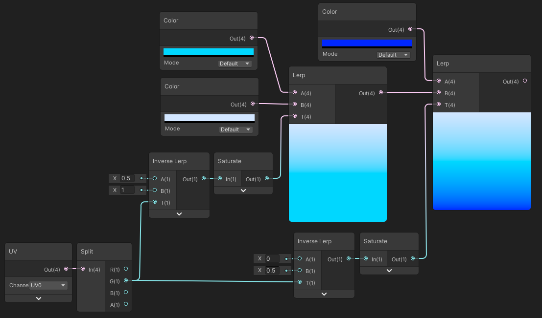
The nodes that sample a cubemap expect a cubemap texture asset
As Remy said you'll have to compile the images into one cubemap texture, according to the vertical or horizontal layout shown earlier
It can be done in any image editor but I prefer the Image Sequencer of VFX Toolbox
what's the super cheapest way to get one channel triplanar mapping onto an object?
I'm thinking something like this but for unity https://www.artstation.com/blogs/daanmeysman/WzzV/cheap-triplanar-mapping

Cheap triplanar mapping optimized world aligned in unreal
I really just want one channel, black and white
I think that's the same as any triplanar implementation, but sampling a single channel texture instead of an RGB texture
perhaps, but I've seen people talk about solutions that avoid doing 3 texture lookups per pixel, which is I guess the more important part
you can use world space normal to blend(or switch, since you cant blend UV) worldspace coordinates (XY, XZ, YZ) to be used as uv for sampling the texture.
There's a trade off though, it may result on a noticable seam
I have the following HLSL code for a custom function in shader graph, which works perfectly fine (basically just the sample texture 2D node at the moment)
#ifndef BIOMES
#define BIOMES

void Biomes_float(UnityTexture2D Tex, UnitySamplerState SS, float2 UV, out float4 Out) {
    Out = SAMPLE_TEXTURE2D(Tex, SS, UV);
}

#endif
however, UnityTexture2D and UnitySamplerState are not defined types, so my code editor is complaining
Cannot resolve type: 'UnityTexture2D'