
#archived-shaders
1 messages · Page 69 of 1
Here is what I have for the new calculation

I replaced both that and the original calculate difference section.
oh man that's a lot of nodes
should be an option to change the bridge coloring so you don't forget which goes where
Try averaging and then checking if it's negative!
what do you mean by checking if its negative.
Oh wait, averaging it makes it look like the outlines but inverted. so the part where the outline should be is the only visible part of anything.

That makes sense! That's what I mean about checking if the summed value is negative
You could even just negate the whole thing
And that would probably give you a good result
Or use one minus your value
I subtracted the value but now it looks like its just brightening everything a bit.
Without outline

with outline

Try using saturate on it to make sure
Saturate is shorthand for clamp to 0-1 range
Doesn't look like you're getting an outline either where you should either
You might need to play with that range of values a bit
Uh, yeah no matter how I set the values it seems to just either brighten or darken everything.
I don't really get the outlines
I did saturation and it fixed the brightness, but I still don't have any outlines.
At the moment it looks like it did when I added quantization.
but, with only quantization
go back to this result, multiply the shit out of it, saturate it, and then sub it from the original color
additionally you could do a step node after the saturate before the sub
to get extra crispy outlines like lethal company
what do you mean by "multiply the shit out of it," multiply it by what?
or a very small number
or add to it with a number
if the math doesn't make sense sometimes it helps to just push things around until you can feel out what the right numbers are
not if we want strong outlines
we want them right?
ye
this approach wont get there super easily actually
thick lines are gonna need a lower resolution
or introduce artifacts
but should give some nice sharp lines
I would say first we cannot even see the outlines
once we see them we can work on makin them thicc
totally -- yeah you need to bring them in by shaping the number you're getting out the dot product. You might even want to bring in a couple of sliders in the C#.
This
You mean like, settings in the post process override?
Ok just looked at this again and as long as your process is
sample normals -> dot product everything against the center -> add up result -> divide by 8
since rn it just has intensity
you should be fine
yeah! I'd add those as settings in the postprocess override
basically like
debug sliders for yourself
just to understand what's going on
Yeah, this is what I have when I do that

to test things
how do I add sliders?
I'm not sure how I would do that

I made it to where I can change outline color sorta.


wooh!
I don't exactly know how to modify the result of the dot product to make the outline function as expected.
I was able to solve it by adding
sample normals -> dot product everything against the center -> add up result -> divide by 8 ->** saturate -> oneminus**
saturate ensures that its in the range 0-1 so that when i use oneminus i know it will properly invert the values
in cases like that its just nice to add coefficients basically -- little sliders to play around with that help you understand where the values are -- when you start seeing the line come back in etc. just by adding adds and multiplies
with those parameters attached to them
Hmm, alright, well now the outline is technically working, but it doesnt really look like anything.
the dot product is from linear algebra and its super useful and pretty simple.
dot (float3(x,y,z), float3(u,v,w))
becomes
x*u + y * v + z * w
This is what it looks like with a black outline

and this is with white

so I know that the outline is there, it just doesnt look like it because its only at dark parts
this is where multiplication w/ those extra sliders can help a lot
you're kinda in an artistic experimentation stage
you've got the tools you need
now you just need to fiddle them into place
so I'd add as many levers as you can
sliders from C# will be really helpful
remember graphtoy is super helpful for visualizing how math functions shape numbers
I found how to increase the intensity of the outline, but I gotta figure out how to increase the thickness
this is with the outline multiplied by 10

ooooh, scaary wooood

With the current involved method, this will get more and more expensive, or give a blocky effect.
To increase the thickness, you'll need to either check pixels that are further away from the current one (increasing the UV offset of the 8 samples of the surounding pixels), or do an average with more than 8 pixels (the thicker, the more pixels you need)
alternatively you can lower the resolution of your camera
which is pretty much what lethal company does, I noticed when installing a mod that increases resolution, the outlines were substantially less noticeable. Meaning that most of the thickness is caused by lowered resolution.
Plus, since I'm using HDRP, I wanna make sure lower end PC's can run my game.
My friend's crap laptop can run lethal company and it uses HDRP and volumetric fog, so most of the performance is benefited by lowered resolution.
if you want a fudge factor for thicker outlines
kinda a cheat that will add more artifacts
I have a section that allows you to break the pixel perfectness
at the start
called "extend"
that might be a fun place to put a slider
its going to create some strange artifacts tho
Just added a slider and it looks a bit odd, might use it later though for weirdness.
This is looking even closer, now all I need is thick depth outline.
Which should be pretty easy

IDK if any of these resources will help your use-case, but I keep them around "for fun". Haven't followed your entire conversation, so please excuse the intrusion if not applicable.
https://www.youtube.com/watch?v=5EuYKEvugLU
https://bgolus.medium.com/the-quest-for-very-wide-outlines-ba82ed442cd9
https://alexanderameye.github.io/notes/rendering-outlines/

In the realm of image based edge detection, aesthetically pleasing edges are hard to come by. But, what if we could get stylized edge lines by just blurring our image twice?
Download my GShade shader pack!
https://github.com/GarrettGunnell/AcerolaFX/wiki
Patreon: https://www.patreon.com/acerola_t
Twitter: https://twitter.com/Acerola_t
Twitch: ...


🖍️ Explaining multiple techniques for rendering outlines and highlights for real-time applications. This includes vertex object-space as well as screen-space methods. This can be used to render outlines in Unity or Unreal. Outlines can be used for gameplay reasons or aesthetics.
Jump Flood Algorithm seems where it's at huh
that's going to be another weekened for that
I got vertex extrusion working alright, but seems to get drunk when putting it on some really detailed stuff (when extruding far enough)
Silhouette technique works as a backdrop fine, but I can't get the sorting down, so maybe I'll try stencils with it
Hi, I am trying to offset sprite vertices via shader and it seems like it has too few to look nice.
Is there a way I can somehow increase the number of verts it has or is that automatically calculated?

Try sprite editor's "custom outline"
hey, i'm trying to make a 2D point light that works with normal maps. i'm getting view space normals (in picture 1), by making background color (0.5f, 0.5f, 1.0f, 1.0f). and rendering normal maps. then im rendering point lights with this shader code. i made a simplified version with no falloff to check. heres the code.
            fixed4 frag(v2f i) : SV_Target
            {
                fixed4 col = _LightTempColor * _LightTempIntensity;
                float4 normal = tex2D(_ViewSpaceNormal, i.scrPos.xy);
                float3 dir = float3( _LightTempWorldPos.x, _LightTempWorldPos.y, _LightTempWorldPos.z) - float3(i.worldPos.x, i.worldPos.y, 0) ;
                dir = normalize(dir);
                float dotMult = dot(dir, normal);
                col *= dot(dir, normal);
                return col;
            }
the problem is, dot product looks weird. theres this black diagonal line, when i change lights z position, the lines position also changes

i have no idea why dot product is like this, help
this is a test and i'm not using any attenuation here thats why its cube by the way
The dot product will return approximately zero when the two vectors are approximately orthogonal to one another, and negative values when they face away from one another
yeah, the problem was normal map
since view space normals are between -1 to 1
i was packing the values to be between 0 to 1 by doing (normal*.5f)+0.5f
but i forgot to unpack them here
the solution was just doing normal=normal*2-1
and it got fixed
woops wrong channel
does anyone have an idea of how to make a compute shader that gets the mass of an object and deforms it on a grid so it looks like this

why do you need a compute shader for that
thats just a vertex shader, pass in the positions and masses into a buffer and thats it, you can deform the grid using that data
Well if it's for a visual effect and there isn't a worry about colliding with the grid. Then a compute shader would run better since it would be running on the GPU. not sure if that's why they want one but just a thought.
actually all shaders run on the gpu! vertex shaders are probably the way to go just to avoid headaches with platform / graphics api support -- your heart of your code will look pretty similar either way
- expose an array of positions to your shader and masses
- using said masses calculate an offset for the vertex
- apply it
the catch with a compute shader is you'll need to write a lot more logic to bind things like the mesh data to the gpu, manage the lifecycle of the shader, and manage thread counts
what you get as a perk is that you can send structs to the gpu and organize your ideas a little better, and importantly you can keep track of vertex positions over time. So if you wanted to make a spring for example for vertices you'd be able to do that w/ compute. Vertex shaders can do it too but need to be set up similarly to a compute shader to do it.
At the same time you also have to keep track of the size of those structs and be very specific about memory.
Do you have a boilerplate for writing compute shaders?
hi - im using default render pipeline with shadergraph and the shaders seem to not be compatible with multiview, its only visible in one eye
anyone know how to enable multiview for my custom shadergraph shaders?
It should be enabled out of the box in shadergraph! It's always a little more setup in vertex fragment. Is there a node you're using that's dependent on the eye?
i'm not sure. I'm on and older unity version still, 2021.3.34, do you know if it always worked, or was added along the way?
Im using position nodes
not sure if those are dependent. Also fresnel - that may be dependent on eye position??

o ok thanks

oh hrm -- here's everything a shader needs to render in both eyes. I'm not sure how to apply that to shadergraph yet: https://docs.unity3d.com/Manual/SinglePassInstancing.html

some of the macros need to be in the structs which I dont think you have access to
You might be able to inject other ones into fragment and vertex by adding custom code nodes that are parts of chains that lead to vert / frag in nodes.
but it feels like a stretch
Im thinking of updating to latest unity version and URP
Im just picking this back up, but people used to say stick to BRP
not sure if thats still true though, im seeing people on reddit say how they use URP now
No double posts pls
got it - at first I was posting about the shader issue, then when URP came up, i asked in the URP chat
Hi guys, is there a way to make a shader either:
-look the same when the plane is right-side-up and when it's upside-down
or alternatively:
-make the shader itself makes its effects apply upside-down instead of rightside-up?
Because what I am dealing with is... needing this water plane to be upside-down (Z rotation 180) in my game. But the water shader looks different when the plane is turned upside-down, which I don't want

hi! what's the shader that you're working with ?
Those are both doable things but depend on the shader you're working on as to the specifics
oh! if it's about changing things in the actual shader graph, I will revisit this question when i'm happier with the shadergraph. This is just a placeholder one and it's very chaotic so I'd rather not get help changing this one specifically. But Thank you
For right side up-ness I'd look at things like negating or taking the absolute value of the object y position wherever you're sampling it
same for the normal
where you use it
Okay, thanks! I'll try that when cooking up the next one.
I just got depth outlines working with the normal outlines, and I can make the outlines thicker if I increase the extent. But I am getting this gradient due to being at an angle. How can I fix that?

is that coming from the normals or the depth ?
Depth
also, why is it taking 10 years to load just from me moving a single object in the scene?
It's probably not post processing related! That's really strange.
the depth thing isnt related or the taking 10 years to load?
The 10 years to load. Does it tell you something when you do that?
The depth thing is definitely related and something I think you'll need to change the comparison technique for slightly. This part is going to be a bit trickier.
No, it says unity.redraw or something
For a solution to the grazing angles issue I recommend looking at the way that EdgeDetection in the HDRP samples handles it.

their solution is to find the smallest dot product between the view direction and each normal
and then multiply that by the depth edge detection
so if the angle between the camera and a point is perpendicular it will give a value of 0
hi, im pretty new to using shader graph and have this set up to simulate darkness in a 2d terraria-like game. in code im calling setpixel and editing the texture depending on the intensity.
that's all working fine, what i'd like to do next is add some kind of circle i can put around the player to cut through this texture and see regardless of the darkness level. i wanted to google a guide to follow but i dont know exactly what im looking for if someone more experienced could put it into words ❤️ thanks

its nice that you're using the absolute world as coordinates! this will make things a lot easier
you can set parameters on materials using material.set__
in your case you want a new vector2 for your player position
so in c# you'll need to write
material.SetVector("_PlayerPosition", player.transform.position) (or something like that)
in the shader - you want to cut a hole out around the player -- the best way to make a mask like that is to measure the distance between the position you have in absolute world units
and the position of the player
you can then use the distance as an input to a smoothstep function to define the edges of the circle
with a light feather
I just applied that and two things just happened. One, it appears to be a bit messy with the outline now. Two, holy crap this shader graph is a mess.


I highly recommend looking at the book of shaders for this to get a better intuition: https://thebookofshaders.com/07/

The Book of Shaders
Gentle step-by-step guide through the abstract and complex universe of Fragment Shaders.
ok so leading up to this point I've been helping you work with shadergraph and its a really easy way to learn the api but pretty cumbersome to work with for loops like this. if you wanted to clean things up a bit you could start to put things into custom hlsl nodes.
thanks @deep moth , ill try that
good luck!
Hmm, like what?
You mean put some of the groups in custom nodes?
the nice thing about custom functions is you can use things like loops
if you pick up a little bit of hlsl it'll go a long way
its what shadergraph is making under the hood
Yeah, I know what hlsl is, the only reason I'm not using it currently is because it looks very complicated.
Though, I guess the first thing I could do is move the offsets group into a hlsl script.
How could I convert this?

that i think works best as shadergraph nodes -- you could make a subgraph if you really wanted to pack them together
but as hlsl the core function would look something like
{
    upperLeft = float2(-1,1);
    upper = float2(0,1);
    upperRight = float2(1,1);
    etc....
}```Ah, so it would just be just a large node with 9 outputs
just to get that offsets group in there
i dont think its worth it unless you can see a nice use for it
but!!
Yeah, it wouldnt change much
yeah actually now that I'm thinking about this
it's gonna be a lot of work to get the HLSL working because you'll need to figure out what each node corresponds to in HDRP. the documentation is good at it but it'll be annoying.
the reason i was thinking you might want to approach things like that is that you could write
{
    float2[8] offsets;
    offsets[0] = float2(-1,1);
    offsets[1] = float2(0,1);
    offsets[2] = float2(1,1);
    etc....
    for(int i = 0; i < 8; i++){
        float2 offset = offsets[i];
        ~~~ sample here ~~~
        ~~~ do some math ~~~
    }
    ~~ compare results ~~
}```you get cleaner results in someways but other kinds of messiness
anyway right now it's hard to tell why the outlines are scratchy in your graph. if you send multiple screenshots i could look more closely.
Okay, let me do that rq.


Wait, do you mean screenshots of the shadergraph?
yeah! but these are really helpful too
it seems like its scratchy actually more-so because of the normal map


it kinda looks like its doing what its supposed to
thank you!
it does look very thin on the capsule tho
Yeah, it looks like it stops being scratchy if I remove the normal map.
But I don't want it to be scratchy.
How can I solve that?
i dont know off the top of my head but so far:
we look in a 3x3 grid and compare change in depth and normals. filter that by the amount of difference between the camera angle and the normals. then combine those outlines to get our final mask.
the issue right now is that the filter for outlines at sheer angles is overcorrecting
its doing what it should by comparing the normal from the image with the view direction of the camera
but it's doing it when there should be an edge rendered there
maybe what you could do is only start to apply the filter for grazing angles when it starts to get extreme
you could use a smoothstep (.1, .3, grazingAngleFactor)
and that would give you a nice transition from when it starts to become grazing to fully grazing
you might have to flip the numbers around a little
"in the shader - you want to cut a hole out around the player -- the best way to make a mask like that is to measure the distance between the position you have in absolute world units"
im having trouble figuring this out, whatre the important nodes i need to add to the existing shader graph i have? i already added the vector 2 and have the player position accounted for in code and updating
Great!
you want a distance node
and then to begin with i'd try a step node
just to get a sense for how it works
(eventually using a smoothstep to avoid artifacts)
then you want to multiply that with your shadow
in pseudocode it would look like this:
float distance = distance(playerposition, worldposition);
float mask = step(distance, radius);
shadowAlpha *= mask;
does this look about right or did i go wrong somewhere

some corrections below:
distance
A = playerPos ✅
B = absoluteWorldSpacePosition (node you have above)
step
edge = range
in = distance
what is the 2nd Edge if using smoothstep?
so step is basically
if(in > edge) {
  return 1;
} else {
  return 0;
}
smoothstep gives you a gradient between those numbers instead
so you need to input the range it should go from 0 to 1 across
before Edge1 its 0
after Edge2 its 1
between them its somewhere in-between
so a good place to start a lot of the time while you're testing numbers is to set them to be something very similar
it'll look something like step
then start adding to both of them to get a wider feather
one pattern I use a lot is this:
smoothstep(range - feather, range + feather, distance)
its nice because you only have to work with two variables but still feels like a step function
nice, thank you. just need to work on the feathering now. if i wanted to do this for like torches or something too, do i just create a new instance of the material and apply it to that?

you mean like this?

with this approach your best bet with torches is to make them all variables in your material and have a maximum number.
the approach is definitely best for just one in shadergraph
another way to approach the problem would be to make a render texture where you draw all of the lights
as quads
and then multiply that render texture with the texture you have right now to use that as a mask instead
i'm not sure which approach is more efficient since rendertextures can be demanding on some platforms
yep! and again those numbers are things you'll want to play around with so making them parameters is probably a good call
thank you again, really appreciate your help and insight ❤️
np : )
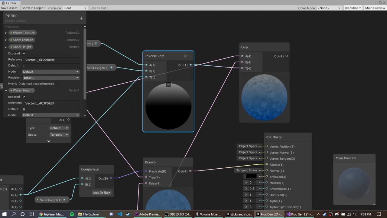
I was following a tutorial to texture my island, the shader works fine except it seems to be working on the wrong axis. Here's a picture https://imgur.com/a/FLVwt0t. This is the tutorial I was following, it is intended for URP but I am Using HDRP https://www.youtube.com/watch?v=uJSxqr3a0cA. Heres the shader's generated code https://github.com/jacklaplante/Unity-URP-Terrain-Shader/blob/master/Assets/Materials/Shaders/Terrain.shadergraph.
Please help me rotate or find an alternate shader to use.
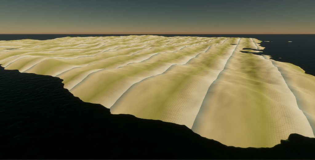
DOWNLOAD THE PROJECT HERE: https://github.com/jacklaplante/Unity-URP-Terrain-Shader
FOLLOW ME ON TWITTER: https://twitter.com/_snubber
This tutorial explains how to use the new shader editor graph to create a shader for procedurally generated terrain that works in the new Universal Render Pipeline in Unity.
Hi, I am trying to overlay a colored noise pattern on top of a solid color and it does work but there is a slight issue.
If the base color is black/something dark it is fine because the noise is being added on top of that.
If the base color is white, the noise being added is p much dismissed because that value is already 1 and there is visible noise.
Using a multiply node won't do it because what if the base color is black, no noise will be visible cuz everything is multiplied by 0.
Thanks in advance!


hi there! I'm 90% sure this is because you're blending based on the UV.y component. For something like this I would expect to be using the world position y instead.

let me try thta out
hi enenra -- you might want to try a blend mode like replace and then plug the noise into the opacity.
oo hm actually i think i missed something
you're looking for a way to blend two opaque things
I am not seeing a replace blending mode so I tried overwrite and it doesn't appear to work

yeah, like if you were to have 2 objects in the world with alpha blending
i think that works about those usually is that one has an opacity
but in your case you have two fully opaque things
it looks like your maintex has an opacity though
when I swapped out the uv for absolute world, it gave me an all white super bright color
there must be a way to make the noise transparent instead of the black background, no?
that makes sense! try puling down the SandHeight, SnowHeight etc
in the material
ok
would that be because its multiplying the color by the height and now the obsolute world pos?
yea! definitely, you have the original noise node right? you could try plugging that in.
that actually worked 💀

wooh!!1
thanks a ton, never would've thought of that 0_o
np !!
it looks like the way this shader thinks you basically in world space have different layers right

and you use inverse lerp
which takes a range of non-normalized values
and makes them normalized (range 0-1)
changing my height value does work, but i have to multiply ~100x what they were prior, thank you
I got something working, now I just need to figure out how to increase the width of the outline.

Would there be a shader that could rotate sprites based off of player position? I'm trying to make it so that my tall grass reacts to my players presence without colliders/animators.
The tall grass are sprites on a tilemap in a 2d scene.


Yeah, usually you'd have two types of shaders that interact with each other
I got it working by setting Edge1 to a value higher than Edge2
actually I forget the details but let me find a video on the subject
yesss!! that looks super sharp
https://www.youtube.com/watch?v=AmO7k-Lr0XM
Ned's usually got some good stuff

✔️ Works in 2020.1 ➕ 2020.2 ➕ 2020.3
Grass renderers are complicated! I've explored a few different ways to handle them, and in this video, I'll add character interaction, or trampling, to my shader graph implementation. I show how to create a renderer feature to upload character positions to shaders, and then how to access that data in a shade...
looks like he uses render object though but you can probably shove it into a shader
if you're familiar with shaders that dissolve walls (if your camera is to close as an example), it's very similar concept too
Hmmm, I'll look into it... I'm a little worried translating to 2d and tilemap. I'm not that knowledgeable about shaders although i have slammed my head into them a couple times.
I'd actually do this stuff in hlsl, but I find doing sprite stuff in URP a pain because _MainTex is used as _BaseMap and a lot of unity structs and methods pass by that variable. Last time I was working it in I had to chop up a bunch of structs just to rename everything.
Shadergraph is a bit more friendly as you can change the reference name to MainTex_
It's just what SpriteRender expect is the problem
So, increasing the extent mostly works to make it thicker, however, it appears to have a really weirdly thick outline beside the bean over the wood, and normal one over the sky.

I believe the reason for that is that is because of our is-sky check
i think that only needs to be there because of the normals
so you might be able to get some thickness back w/ the depth
if you just apply it to the normals
Now that solves that problem, but now I am getting these funky lookin spikes at corners of the plane

Hmmm. What do they look like when you decrease the extent?
They dont appear when I decrease the extent, but that also makes the outline thinner.
might be a trade off unfortunately : (
you're basically sampling in a circle around the pixel
so if the circle gets really big your error is gonna increase with it
so one way to get more accuracy is to add more samples
but that's gonna slow things down a lot
another is to use a fancier technique like jump flooding
another is to decrease the resolution
since it makes pixels and therefore outlines
bigger
Hmm, I think since I'm lowering resolution anyway it should be fine, because the weird corners should also disappear with a smaller pixel amount.
what is the default of scene color in transparent materials?
I tried with uv, world and object position, nothing gives the same result as "default"

nevermind found it, it's screen position
How can I use volumetric fog in hdrp?
I made a Local Volumetric Fog asset but it isnt doing anything
Wait, does it only work in game?
Hdrp lighting is weird

You might have better luck in the HDRP chat instead of the shaders chat for these questions!
is there some way i could modify the bottom row so that the bottom row uses pixel information to place these cutouts in the texture? i have a shadowTex which is the terraria-like 2d darkness over the tiles. i also have a second candleTex which is keeping track of which pixels in the grid have candles and should be lit up. the way its set up in the screenshot i can only place one candle using candlePos, i want to scale it so i can place more

Would you send a screenshot of the candletex?
is it "cheaper" to animate the seed of a procedural texture or the uv coordinates of a shader?
I believe the procedural texture is generated from scratch every frame so it wouldn't matter
It'd be cheaper to animate the UV coordinates of a pre-generated texture though
Hi guys, i created a Texture where each pixel is set using a Vector3 ( x,y,z). In the Shader Graph can i retrieve all the positions from the color of each pixel?
Do you mean this as a solution to some problem?
I want to draw 500.000k + points and i looking for the best solution
Did you look at VFX graph ?
Vfx uses the particles system right?
You can store the points positions (and other) in "attribute maps" (basically, textures where each pixel is a single point data), and use it to display as particles
VFXGraph is the new particle system, using GPU for simulation and rendering
i will take a look, right now i use a shader where i have a ComputeBuffer for the position, and i draw with Graphics.DrawProceduralNow(MeshTopology.Points, pointsPosition.Length, 1);
shader code is simple `v2f vert(uint vid : SV_VertexID) {
v2f o;

float4 pos =  UnityObjectToClipPos(_Positions[vid]);
uint icol = _Colors[vid];
half4 col = half4(
    ((icol >> 16) & 0xff) / 255.0f,
    ((icol >>  8) & 0xff) / 255.0f,
    ((icol      ) & 0xff) / 255.0f,
1);
o.pos = pos;
o.col = col;

return o;
}
half4 frag(v2f i) : SV_Target {
return i.col;
}`
The color is encoded in an integer
Btw i'm new to Unity and Shader, this is a project for my Thesis
Why encode the color in an integer and not simply use a RGB texture ? 😅
Because the colors i receive are already encoded
Hello, I'm trying to wrap my head around inverting the distortion of an equirectangular projection. Here is my shader code that is working for showing equirectangular projection. ```// Vertex shader
v2f vert(appdata_img v) {
v2f o;
o.pos = UnityObjectToClipPos(v.vertex);
    // Convert from 3D coordinates to spherical coordinates
    float theta = atan2(-v.vertex.x, v.vertex.z);
    float phi = acos(-v.vertex.y / length(v.vertex)); // Note the negative sign for Y


    // Spherical Rotation is between (-1, 1), so you can add +0.5 to the shader to rotate it!
    // Map spherical coordinates to UV coordinates for the positive X face
    o.uv = float2((theta / TWOPI) + _EquiRotation, (phi / PI));
    return o;
}
fixed4 frag(v2f i) : COLOR {
float3 unit = float3(1.0, 1.0, 0.0);
// Adjust UV for negative X face with equirectangular distortion
float phi = i.uv.y * PI ;
float theta = i.uv.x * PI;

unit.x = sin(phi) * cos(theta);
unit.y = -cos(phi);
unit.z = sin(phi) * sin(theta);

return texCUBE(_MainTex, unit);
}```
How would I invert the distortion caused by the projection? Instead of blowing up the center of the screen, I wish to push it out, like a fish eye lens; so I can see more of the surrounding cubemap views (y+, y-)

(this is just a fish eye shader applied, but I want to achieve this look by inverting the distortion of the equirect projection)

Thank you
How can I (do I need to?) tell a shadergraph shader to render on the GPU instead of the CPU?
No need
Shaders are all on the GPU
Ah thanks
post wall of text or link?
What?
somebody say to post my shader here
Pastebin
Pastebin.com is the number one paste tool since 2002. Pastebin is a website where you can store text online for a set period of time.
how to change color
You may need to put more detail into your question
its always black
color option in editor will be nice but setting color by value inside shader will suffice
I am trying to read the generated code from an unlit shader by shadergraph, and I just can't parse any of it
the shader is really easy, but the generated code is extremely long
Does anyone know how I can find the vertex and fragment functions?
there is #pragma vertex vert, but there is not function called vert
That's common. Generating the decompiled shader graph code will give you everything, thousands of lines. I believe they are usually near the bottom?
I searched all of it: https://pastebin.com/qKTbnGRs But I am not able to find them
Pastebin
Pastebin.com is the number one paste tool since 2002. Pastebin is a website where you can store text online for a set period of time.
It's usually in an include file, e.g. https://github.com/Unity-Technologies/Graphics/blob/master/Packages/com.unity.render-pipelines.universal/Editor/ShaderGraph/Includes/UnlitPass.hlsl
But if it is in a standard include file, how does it contain my custom shadergraph logic|?
Does anyone know if this amplify shader editor generates better code? I am following a tutorial, and there they use shaderforge and their decompiled code is really clean and nice, but its also quite a while ago
ah ok I see, the shader calls the functions defined in the code
thanks
but its really unfortunate that its so hard to take a quick look what the graph is actually doing :/ But there really is now simpler way around this, yeah?
- Ok, so the shader graph generated code (what my nodes do) is happening in
SurfaceDescriptionFunction - However, that function is not called https://github.com/Unity-Technologies/Graphics/blob/master/Packages/com.unity.render-pipelines.universal/Editor/ShaderGraph/Includes/UnlitPass.hlsl
- The generic shader above only calls
BuildSurfaceDescription. But that is not in the include file and even when I do Ctrl+Shift+F to search the whole repo in Rider, I can't find the definition of that function.
does anyone know how to proceed to find where my code is called and get a full picture?
It's called in https://github.com/Unity-Technologies/Graphics/blob/master/Packages/com.unity.render-pipelines.universal/Editor/ShaderGraph/Includes/Varyings.hlsl, which is included just before UnlitPass.hlsl
ah ok, I just checked the includes of UnlitPass itself, since I thought if it relies on something it will include it
but its dependency is included in the main shader file?
probably because shader code doesn't work with multiple includes or something?
thanks!
I made a shadergraph material that appears on a 2D sprite (circle). When I use this material, the circle reduces to a 12-gon. How can I prevent this?

You're usually meant to sample the _MainTex reference and use it's alpha channel
@ebon basin @regal stag that was it, thanks. I made a circle shape and plugged it into the Alpha. I didn't see it right away, I had to adjust the Fragment node
Ah, right so the sprite has soft edges. but it's basically a quad circle with less verts

i have a shader graph like this to create a of 2d fog effect
but when i change parallax mult here
the noises zoom out for some reason
i am only changing tiling and offsets offset value, so how does that even happen
i want to create a parallax effect for fog and layer it here by multiplying position with parallax multiplier
i guess world position node was something different
i set camera position as a global vector and used that instead
and it worked
so how i change shader color
Add a color property to your shader (properties section of shaderlab, or blackboard in shadergraph), and change it on the material.
i think it havent worked
Show what you've done
here
I see not color in you properties block
return tex2D(_MainTex, float2(input.tex.xy)) * float4(1, 0, 0, 1);
you need to multiply your texture color with your custom color
I'm not sure why would you want to use billboard shader on text, but...
return float4(1, 0, 0, tex2D(_MainTex, float2(input.tex.xy)).a);
yes now works
because shader uses way less resources than rotating text towards you with code
that make sense 🤔
though i might not rethinked it fully
as sure <color> in text would be easiest way for changing colors
any reason why these non functional with shader on?
you need to get the vertex color from the text mesh and pass it to the fragment shader
Hi, i'm trying to put a procedural skybox in VR. Note that I'm not working in my own project, I'm modding Blade and Sorcery, so my access to things like project settings is limited.
I tried both making a pure code shader, and a shadergraph. Both won't show up in vr, and setting that aside it seems like shadegraph doesn't like to be used as a skybox even without vr, in the editor iit's all funky.
I searched a couple posts online and they suggested to add seemingly mysterious magic macro-like instructions in the sahder, and I did, but I still don't see it in VR.
This is my basic setup, is there anything obvious i'm missing?
Shader "Procedural Skybox"
    {
    SubShader
        {
        Tags { "Queue"="Background" "RenderType"="Background" "PreviewType"="Skybox" }
        Cull Off ZWrite Off

        Pass
            {
            HLSLPROGRAM
            #pragma target 2.0
            #pragma vertex vert
            #pragma fragment frag

            #include "Packages/com.unity.render-pipelines.universal/ShaderLibrary/Core.hlsl"
struct Attributes
                {
                float4 position : POSITION;
                float2 uv : TEXCOORD0;
                UNITY_VERTEX_INPUT_INSTANCE_ID //Insert
                };

            struct v2f
                {
                float4 position  : SV_POSITION;
                float2 uv : TEXCOORD0;
                float4 world_position : TEXCOORD1;
                UNITY_VERTEX_OUTPUT_STEREO
                };

       v2f vert(Attributes IN)
                {
                v2f OUT;
                UNITY_SETUP_INSTANCE_ID(IN);
                UNITY_INITIALIZE_VERTEX_OUTPUT_STEREO(OUT);
                OUT.position = TransformObjectToHClip(IN.position.xyz);
                OUT.uv = IN.uv;
                OUT.world_position = mul(unity_ObjectToWorld, IN.position);
                return OUT;
                }

            float4 frag(v2f IN) : SV_Target
                {
                return IN.world_position;
                }
            ENDHLSL
            }
        }
    }
Looks like you have the right macros, but missing #pragma multi_compile_instancing to add instancing support.
oh, where do i need to add that?
Anywhere inside the HLSLPROGRAM block, as long as it's not inside any other block. Next to the other pragma lines is fine.
alright, ty!
I've seen somewhere it is possible to remove tiling and offset properties from a 2D texture property. (Shaderlab HLSL)

Add [NoScaleOffset] attribute before the texture property (in Properties section at top of shader file)
done that but still doesn't work.
The skybox is visible from the game window, but not from the VR visor.
A different material (still handwritten shader) used on a mesh on the floor works just fine in vr in both eyes, it's just a skybox issue
Is the game view mirroring the VR view or do you have a separate camera for the monitor?
can do both. When mirroring vr view the skybox isn't there. When using a separate free camera, the skybox is there
while the material on the mesh works in any combination of settings
And it didn't even have this 😅
#pragma multi_compile_instancing
Are you sure the VR camera has its Clear Flags set to Skybox?
that part i cannot check
Note that I'm not working in my own project, I'm modding Blade and Sorcery, so my access to things like project settings is limited.
Then you'll have to ask elsewhere. This server doesn't allow modding discussions.
oh i missed that my bad ;-;
hey, anyone knows if it's possible to pass bools in structs to a compute shader? I have a struct with all kinds of properties that I send an array of to a compute shader, and until now the data's transferred fine but once I added 2 bools at the end it broke
https://i.imgur.com/LjLfGRU.png https://i.imgur.com/zC0gjaY.png https://i.imgur.com/8sYqfnR.png
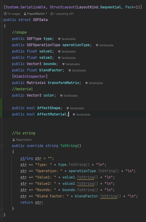
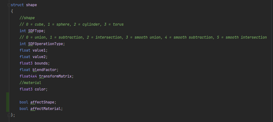

I think it should work. What does UnsafeUtility.SizeOf return for SDFData? This might be a padding issue.
returns 110
What about without the bools?
108
is there a way to make structs automatically the size of the closest multiple of 4 or something? or do I have to manually adjust padding every time I change variables?
You could try adding this attribute to the struct:
[StructLayout(LayoutKind.Sequential, Pack = 4)]
Not sure if it affects UnsafeUtility.SizeOf.
just tried that it ended up working, thank you
I misunderstood what pack actually did
nvm there's still a problem, first struct in the array seems to work fine but the 2nd one gets messed up when read by the compute shader, possibly because the bools aren't being sent or something so there's misalignment?
gonna try just changing them to ints at this point
that fixed it, go figure
I forgot, bools are 4 bytes in HLSL 😬
So you should be able to have them as ints in the C# struct, but as bools in HLSL, if you want.
is there any reason they're 4 bytes? that seems like waste
Just to ensure that structs are always 4 byte aligned, I believe.
WebGL never ended up getting compute shaders, so no. Eventually when WebGPU support is fully fleshed out in both in browsers and Unity it should be possible.
This is the last update I saw on that: https://forum.unity.com/threads/early-access-to-the-new-webgpu-backend-in-unity-2023-3.1516621/.
I want to make an effect that required position to get distorted in voronoi pattern. Basically it takes the UV and output the position of each cell.
1st image is UE which has a vector noise node. 2nd image is from blender, which has a position output in voronoi node. In shader graph I dont see anything like this. How do I achieve this?


The best is probably to find a voronoi noise function that directly outputs the cell center position in some way.
But if you want to use strictly shadergraph, here is two ways to do it, both calculate the X and Y variation of the voronoi, and use it to shift the UVs. Some nodes (inline floats and multiply) can be used to tweak the results


@remy for the rescue once again, LOL
Unity Forum
Hi,
I want to make this kind of effect in shader graph:
[IMG]
https://github.com/keijiro/KinoVoronoi
I want that each voronoi cells show the color...


Note that the second one is obviously more expensive, having to do 5 noises in total.
And the custom function node in the forum post is the best way to do it 😅
@uri nice. Yeah that function is gonna come in handy. I was searching for something like this. Helpful to know all the tricks though.
Hey Remy did the ability to make custom nodes come back ?
Did it go away at some point ? AFAIK custom function nodes never left
No like the c# api for actual custom nodes
There was public API at some point ? I can't remember ...
But by using some ASMRef you can do custom nodes still.

@amber saffron @mental bone thanks for the help. This is what I was working on. I needed 3d noise with position, wasn't hard to do, because I already found some 3d voronoi custom functions. Modified the position/center output.

I still like the handpainted look, but I think I can modify it more and make a completely automated painted filter.
Looking nice
Hey, I can't find any helpfull answers on THE INTERNET.
I'm running rider with unity plugins installed, but it seems that hlsl for custom functions have problems with keywords like UnityTexture2D, SAMPLE_TEXTURE2D etc.
Is there any plugin/fix for this or do i have to use VSC to gain access to intelisense?
looks really nice!
@nova needle Thanks 🙂
When i try to change the shader of a TMP object it changes the shader on all the TMP objects is there a reason for this and how do i make it not do this
I am trying to add volumetric fog, but the posterization shader is making darkness see through and I don't know why?
Here is without posterization.

Here is with it.

seems like TMP use shared material for each font. maybe you can try duplicating the font?
or change the shader via code (get material automatically create an instance of the material)
duplicating the font worked
I am trying to apply one giant texture to an island made on many square chunks, it applies my texture to each individual chunk as its own objetct, how would I apply a continous texture to all the objects in shader graph without tiling?
use worldposition.xz as texture uv
is there anyway to offset a texture thats using a triplanar node?
Hi sorry I'd love to help but I'm super busy this week. The roughened falloff of the light looks really cool w/ the outlines!!
how can I connect the normal texture I have to the normal node? I have no idea what object space means

but as is it wont let me connect the normal strength node to the normal node
Oh, that's alright! I can work on other aspects of the game until you are available.
wrong output, there should be another output node with color, and a tangent space normal soccet.
To output in the vertex stage, you need to use the SampleTexture2DLOD node when sampling the normal map.
I don't remember if the note itself has a space dropdown, else, if it is stuck to output tangent space, you can use the "Transform Direction" node to transform from tangent to object, after the normal strength, and then connect to the vertex normal
Hello everybody I made an endless world generator which uses a ton of different noise layers to generate diverse landscapes featuring different biomes at runtime, as you traverse through the landscape.
It its not texured yet though ... Does anybody knows some good resources on how to approach this? Since I do not know much about shaders or texturing in general I would happily use a third party asset if possible. But since I am creating the mesh myself (not using any build in terrain features); i guess I have to create my own solution.
I would like to texture the terrain based on 1. its height 2. the steepness 3. and the biome.
Any help and Ideas and links to usefull resources are much appreciated 🙂
try searching for terrain auto material
Is that an Asset?
have you searched it?
Question:
how can I get the uv scale inside shader? I want to 'de-scale' the texture uv scaling so the uv size reverted to original size
Yes but nothing comes up ..
I did just to see and its 2 assets that pop up, one is 150$ the other one 60$
Idk if they meant free asset
Ah yep I found it. But thats a hefty price tag also I think its meant to work with unity build in terrain and not on a custom mesh
- i had random search filter set, thats why nothing came up😳
maybe browser does matter (I'm using edge, dont ask why 😅 )
the Geo Grass Auto Terrain Material is free, it's for terrain though

Chrome did not show me this like at all
3 Stars so idk if its actually all that good 😅
Maybe thats why chrome didnt show it
Hello, does anyone why I can't set SRP Batcher incompatible of a custom coded URP shader ? I tried the methods in this doc https://docs.unity3d.com/Manual/SRPBatcher.html
looks super basic i will check it out, so probaly a good starting point. judging from the comments people were using it exactly the way i intend to thanks
Its just one shader file so i should be able to adjust it for my needs (if the base functionality is there)
Ok tried it it doesnt work with mesh renderes; it also depent on terrain
You also have outlines there, which would be my first suspect rather than posterization
I've googled a few solutions but not quite found the answer Im looking for, I'm trying to sample the shadowmaps to allow a shader to "reieve shadows" in URP on 2022.3.7f1 on an UNLIT shader graph with custom lighting. The custom lighting derived from the HLSL is working but for some reason the shadow attenuation isnt returning the shadow map? I think I may be missing a keyword?
I typically use an Enum Keyword (Global, Multi-Compile) with reference _MAIN_LIGHT and entries SHADOWS, SHADOWS_CASCADE and SHADOWS_SCREEN as that is equivalent to what URP shaders define
Also a Boolean Keyword (Global, Multi-Compile) with reference _SHADOWS_SOFT if you need to support that
Hey Guys, I'm using a Sine Time node to rotate UV coordinates. Thing is working just fine but for personnal preference I need the switch from one half cycle to the other to be quicker. On desmos I can achieve this by simply powering the Sin wave by a number lesser than 1 (0.76 in my case). But doing the same in shader graph results in impossible values (that cursed flashy pink) even when powering by one...
Someone know why this happen ?
In shader, the result of powering a negative number is NaN
You can work around it by taking the absolute value of the sin wave to the power, and then multiply by the signe of the sin wave again.
Okay good to know 🙂
r = pow(abs(sin), 0.76) * sign(sin);
Yep just like a charm now 🙂 Thank you !
Out of curiosity, why the result of powering a negative number is NaN in SG ?
Mostly because of powering a negative number to a non integer power is ... nonsense ?
I don't have enough math knowledge to understand how it would be possible to calculate this without removing the sign and applying it again 😅
Desmos calculator use unseen workarounds perhaps ? :/
like, -2 pow 1 = -2 -2 pow 2 = 4 but -2 pow 1.5 = ??? -2.8.. ?
Probably


Not all values of a display a correct wave though

damn you were faster
It's probably graphing -(2^x)
(-2)^x doesn't even show up 😄
there we have it 😄
xD
Yah, IDK what desmos is doing without telling us, I get inconsistant results when trying to power negative values.
Anyway, that "safe power" workaround was the way to go 🙂
Awesome, thank you for that!
I've now implemented the recieved shadows in my simplified custom lighting and it works a bloody treat, you have my great thanks @regal stag!
If I use Material.mainTextureScale to get the texture scale in C# of a material, how do I do this if it is shadergraph, which doesnt have this property?
iirc under the property/node settings there's a "Use Tiling And Offset" tickbox which exposes the fields to the inspector - might also be needed for it to work in code, I'm not sure. These values are automatically applied when sampling the texture, but there's also a Split Texture Transform node which can obtain them
For mainTextureScale specifically, you can also right-click a texture property in the blackboard to set it as the Main Texture
Thanks!!!
Some powers have real solutions for negative inputs, most don't. You need the power to be such that (1 + 2n)/p is an integer for some integer n, where p is your power.
Certainly most real numbers don't fit the bill, I think half of all rational numbers should work (if we rewrite p = a/b with a, b being coprime integers, then we need (1 + 2n)*b/a to be an integer but (1+2n) is an integer so we don't need to multiply by b; then (1 + 2n)/a needs to be an integer, which can be true if a is odd (n = (a-1)/2 and odd-1 is even) and can't be if a is even)
But the way it's usually computed afaik is by doing exp(p*log(x)) = x^p (probably in base-2) and all log(negative number) is undefined for real numbers so it dies there
(if you use complex numbers, all powers of negative numbers are accessible)
How do you deal with textures that are bigger than 8000 pixels?
does anyone know how to fix where the textures are pink and invisible in game?
anyone?
this is an error caused by a shader that failed to compile, or for a shader designed for another rander pipeline
select the pink object, check the pink material, select the shader used by that material, the error usually shown in that shader inspector
Is there a way to choose black as a color in a shader graph utilizing HDR color?
why cant i select a texture from a atlas as my maintexture in shader graph?
Set the color node/property to HDR, and set the value to 0,0,0
Do you mean, a sprite atlas ?
The atlas itself is the only texture, sprites are essentially UVtiling and offset to look into that texture, so if you want to use a sprite in your shader, you need to pass the UV tiling and offset of the sprite alongside the texture.
Then it ends up invisible. 
Are you using an additive shader ?
Ask the question or explain the issue, don't ask for permission
whoops
so basically I had a URP water shader in my VR game, then I went ahead and added "Oculus Intergration" which turned all my textures pink, then when I changed them all back to normal the shader is still pink and everytime I try to change the thing from like lit/shader and allat it just stays pink
and im new to unity and dont know how to fix it :/
So, this ? https://assetstore.unity.com/packages/tools/integration/oculus-integration-deprecated-82022
It has been deprecated apparently :
Oculus Integration has been deprecated in favor of Meta XR UPM Packages. For version 59 & above, please use Meta XR UPM packages instead.
It means that you should stop using it in favor of the new tool
ohh alright, what would be a better one to use? (if you know)
The one mentioned on the page I guess ? : https://developer.oculus.com/documentation/unity/unity-package-manager/
thanks!
So, try with that if it helps, I'm still surprised that the oculus integration broke your project, it states that it is compatible with all pipelines.
Maybe it forced the project to go back to the built-in renderer, making all the shaders incompatible, in that case you maybe just have to assign it back in the graphic settings.
alright ill try that
thanks dude!
it worked
I guess not? I never saw an option to change it.
Ok, that needs more context. How are you using that black color ? What is the shader doing ? Can you post more informations like the shader code/graph ?
Basically, I have a shader for a sphere that has two primary effects to it. One being a fresnel effect and another being a dissolve effect.
In the dissolve effect, it dissolves the sphere from the top side down, keeping the sphere color as it goes down
but on the edge, I have a secondary color for the dissolve I wanted to use black for.
Ah, the reason why it didn't have the option for changing it to additive was I had it on opaque and not transparent.
But the black color still doesn't show up, even when changed to additive.
Are you trying to apply that black color by using an "add" operation / node ?
Originally, when the black color is introduced, I wasn't.
But when I change it to an addition

The black color is just grayish white.
Well, adding black to any color just give nothing. Black is 0, adding 0 to X results in X.
You will need to use a lerp node to blend from the base color to the black color using a mask.
Hi, I have a problem with shader, it works perfectly on 4 PCs, but on one it seems like its invisible, did someone else also have this issue before? Any ideas how to fix it?
What seems different about those PCs? Or their GPUs most importantly
In project or in build?
I feel like this is a dumb question, but how can I (In shadergraph) use the camera direction for UVs, so that I can use any objects mesh as a 'hole' into a skybox that you are inside? As if you are inside the sphere of the skybox and anywhere is that material is punching a hole through to it
some kind of screen position meets view direction wizardry?
not sure i understand quite right, you wanna have it so that this material/shader masks any objects behind it so just the skybox is visuble
🤔 even if the shader is unsupported on other PC, I dont think it should be invisible, usually it just went with the famous pink color (assuming the shader doesnt have any fallback)
well not quite, I want them to BE the skybox - just set their UVs such that when you see this geo it look like it's skybox....
so, lets say I put a teapot into a scene, and then I have a teapot shaped 3d 'hole' into the sky, although in reality it is just how the uv is mapped that makes it look like that (the 'sky' would only ever be seen through these 'holes' (3d pieces of geometry)
yeah, thats basically the same effect as i described, gimme a few miins cause i did that in another project
ah okay, i dont think its possible in shadergraph, unless you want to write some nodes yourself, but basically, you wanna look into something called the stencil buffer, which lets you test stuff based on whats in the buffer. so you'd assign the magic object to the buffer, then in other materials that are getting holes put through, look if the stencil full for that pixel and if it is, discard it which would allow you to see through it
its in office, every pc has the same build
its completely invisible not even pink, can't be seen at all
hmmm, thanks, is a stencil buffer really necessary there? isn't there some maths that would just sample the skybox texture based on some VIEW DIRECTION -> maths -> UVs?
maybe, i could just be over complicating it
Anyway, anyone know if its possible to sample a texture inside the domain shader? atm im getting just using this: float displacement = 1 - tex2D(_MainTex,uv).r; and its giving me an error '[Worker0] Shader error in 'Unlit/tesselation3': cannot map expression to ds_5_0 instruction set at line 129 (on d3d11)'
Any hints on how to smoothen this circle?

ok so I am a fool and I was literally just looking for the sample cube map node 🙈 and piping in view direction
oh damn didnt realise there was a node for that
You mean, to smooth the white to black transition in the output of the fraction node ?
It could be done in multiple ways, here's one :

thanks, don't really understand the idea behind this process but it works
Sorry for not adding explanations.
The idea is that the fraction operation simply removes the integer part of the value, without smoothing from 0.999999... to 0.
What that node setup does is to take the highest values (from 19/20 = 0.95 to 1), and dubtract if from the greyscale.
So instead of doing 0>1|0>1 ... it does 0>0.95>0<0.95....
Then divide by 0.95 to be in the 0;1 range
Thanks!
So I am yet again trying to re-create this system from Valve in shader graph. https://steamcdn-a.akamaihd.net/apps/valve/2010/gdc2010_vlachos_l4d2wounds.pdf Slide 15 holds the relevant shader code. This is the way I did it in SG. Now the thing is I actually have no idea what how to controll the actual elipsoid via the 3 axis. "// Apply rotation and ellipsoid scale. Ellipsoid basis is the orthonormal basis
// of the ellipsoid divided by the per-axis ellipsoid size." this coment from the valve presentation is entirely unclear to me, looks like I decided to skip out of school when they went over this haha. The other problem I'm having is that the blood texture is completly missaligned from the cutout hole left by the elipsoid.


From what I understand of it, you have to pass the ellipsoid axes to the shader.
Take a transform, and pass the Transform.up , .right and .forward vectors.
You can also scale them to stretch the ellipsoid in the matching axis
And scaling them is just a multiplication ?
Right now I believe it is
(btw, either Valve or yourself did typos on el-l-ipsoid 😄 )
But subtracting it from the preskined vetex pos brings it to object space right ?
In that case you need to make sure that the UV3 (which is the pre-skinned position I guess ?) is also in the same space. Simply by using a transform position from object to world would be enough
No, that's an origin shift, but if the values are not in the same space to begin with, you'll end up having some offset that accumulates
I use skinnedMeshRenderer.BakeMesh to put the pre-skinned positions into uv3
Would it not make more sense to transform the elipsoid center to object space ?
So it's in object space.
Then you'll also need to transform the 3 axes vectors 🙂 That's why I suggested to only transorm the position to world
You could also choose to pass the ellipsoid values in the object local space by transforming them in the c# script
I will try this
Ping if you need any help 🙂
@amber saffron so I did this quick test void Update() { if(_renderer!=null) { _renderer.sharedMaterial.SetVector("_ElipsoidCenter", _renderer.worldToLocalMatrix.MultiplyPoint(transform.position)); _renderer.sharedMaterial.SetVector("_ElipsoidSide", _renderer.worldToLocalMatrix.MultiplyVector(transform.right * sideSclae)); _renderer.sharedMaterial.SetVector("_ElipsoidUp", _renderer.worldToLocalMatrix.MultiplyVector(transform.up * upScale)); _renderer.sharedMaterial.SetVector("_ElipsoidForward", _renderer.worldToLocalMatrix.MultiplyVector(transform.forward * forwardScale)); } } now moving the object seems to have correct result bit I think the scaling is wrong. I was hoping that using the matrix would take the object scale into account, so I tried that before adding the manual scales but that hos no effect
It should be the same, but instead of using matrices, I prefer to pass through the transform object and use TransformPoint and TransformDirection
I think that using TransformDirection or MultiplyVector ignores scaling though ....
"When transforming a direction, only the rotation part of the matrix is taken into account." you are right
You could force the scale of the directions using something like this :
localScaledUp = _renderer.transform.TransformPoint( transform.up * upScale + _renderer.transform.position)
It could probably be better done with matrix math, but I always get lost with this.
It samples the reflection probe applied to the object, it does not override the reflection
An example of use would be to fake refraction
Well, you're not so far from doing custom lighting at that point.
Else, I think that if you switch to a specular material and set the specular color to a full black, it should kill totally the reflection.
But it will also kill the specular reflection of light sources.
You could also use light layers (or rendering layers depending on the version you're on) to have that object not in the same layer as the reflection probes, so it will ignore them
Maybe have it use a dedicated full black custom reflection probe instead.
Hum, if there is no environmental reflection (or pitch balck ambiant probe + global reflection probe) no fresnel should be visible
@amber saffron Should it be InverseTransformPoint ? Since we want to put the world elipsoid into object space ? I also tried what you suggested and the scaling still seems wrong. For example if I increaze the z slace the elipsoid seems to get smaler in that direction. _renderer.sharedMaterial.SetVector("_ElipsoidForward", _renderer.transform.InverseTransformPoint(transform.forward * Scales.z + _renderer.transform.position));
Strangly enough TransformPoint yields the exact same results so now I'm even more confused
Just divide by the scale then 🤷♂️ 😅
hmm the original paper did say devide yes
Actually deviding the result of the matrix transformation by a scale seems to have done the trick… I waih there was a way to visualise this mysterious ellipsoid
You could output frac(length(vEllipsoidPosition)) to display the ellipsoid
Like to the base color in the frag shader ?
Sadly I need to go, but do you mind if I ping you tomorrow when I get stuck again 🤣
Yeah, that's what I was trying to say. URP lit shader are supposely PBR, so you if you don't want that fresnel effect, either find a way to remove ambiant lighting, or use a non PBR shader.
Yep.
no pb 🙂
Hello! I built a shapergraph in HDRP to cut holes in my ceiling at runtime. It uses a camera with clear flags set to white and unlit black objects on a layer the main camera does not render to create a render texture. The shadergraph then uses that render texture to do alpha cutout on the ceiling.
This works but isn't terribly performant due to having another camera in the scene. It also falls apart if the ceiling height or dimensions of the ceiling change as the camera no longer sees the objects at the correct distance/size to cut the right size hole.
Is there a better way to do this? Using all the different objects positions in world space or some type of overlap shader. I've been searching for something and haven't found any good answer online.
End goal is just to have a shader or something cut out shapes from the ceiling where ever my recessed light fixture objects are at runtime (In HDRP).
Would be a better fit in #archived-hdrp I think.
But your solution for performance would probably be to use a custom pass to render that mask instead of a dedicated camera.
Thanks. I've been playing with custom passes but haven't been able to achieve the effect yet that way either. Can't find a good starting place to work off of.
@amber saffron sorry to @ you specifically but I have a good feeling you can help. I'm currently messing around with doing bit-packing experiments for textures but I'm having alot of trouble decoding values

so currently messing around with an encoding scheme of encoding color down to 4 bits
and packing them into RG
leaving 16 extra bits for other data
my texture format is RGBA32
8 bits for each channel
This repo might help ? : https://github.com/alelievr/HDRP-Custom-Passes
But else, the idea would be to use the custom pass render object to render to a custom color buffer, and sample the custom buffer in your shader to do the actual curtout.
but on the step of the decoding I can't seem to figure out whats going wrong
I'm able to encode the first channels I have into 4 bits and get them just fine
but the moment i pack another into the same data it gets mangled somehow?
Thanks. That's something I can work off of
tldr my encoding scheme is this
RGBA
R8 - Red Encoded 4 bits | Green Encoded 4 bits
G8 - Blue Encoded 4 bits | Alpha Encoded 4 bits
B8 - 8 bits free for other data I will eventually put in
A8 - 8 bits free for other data I will eventually put in
I switched from doing it from scratch to using the SRP core packing functions here https://github.com/needle-mirror/com.unity.render-pipelines.core/blob/master/ShaderLibrary/Packing.hlsl but stil lgetting the same issues

GitHub
[Mirrored from UPM, not affiliated with Unity Technologies.] 📦 SRP Core makes it easier to create or customize a Scriptable Render Pipeline (SRP). SRP Core contains reusable code, including boilerp...
Did you get rid of possible issue with pixels interpolation and texture compression ?
there is no compression its a standard RGBA32.asset
this is the packing code atm

and the unpacking one
Hum ... if the RG data is read properly when B&A are 0, I don't see why it would break when you store data in BA 🤔


red and blue get encoded correctly, and it makes sense because they are the first 4 bits
but trouble comes when you try to fit the green/alpha color into the other 4 bits
its worth noting that I am using a compute shader atm do run a packing function for the texture
and of course at runtime I have another shader that takes the packed texture and unpacks it
the compute shader has an RT that is set to Float precision
I have set it to ARGBInt also but that doesn't seem to make a difference
Why not RGBA32 ?
I'm not sure to understand how to read the images above.
top left is probably the source color texture ? But the others ?
top left is source color, bottom is the packed texture, top right is the unpacked texture
the unpacking is done at runtime in a shader
my bad should have mentioned what the setup is
but this here on the top right is with all 4 channels "decoded" but the green and alpha values are mangled
the data is there clearly but its not getting decoded properly
Then, I'm a bit surprised to see nothing in the packed texture where the green color should be.
And where the blue is visible initially, I don't think it should look like this 🤔
thats my conundrum lol
but the data is certainly there

here I boosted the brightness of the texture before it gets unpacked
its clearly there
So, to understand : you send a base texture to the compute, that writes in an RT, and that RT is displayed for the "packed" quad, right ?
not quite
here
- BitPacker takes source texture
- BitPacker dispatches compute shader to pack bits
- The rendertexture is then converted and saved to a texture2D
- In the top right quad, there is a shader that takes the saved texture2D and unpacks it at runtime
I sense that since you mentioned only RTs that is potentially where the culprit lies
going from RT -> Tex2D
Have you tried feeding the packed RenderTexture directly from the compute shader without the conversion step to Texture2D between?
Maybe. You could try to display the RT directly, just to check
I'll try that yeah
although if it ends up working that is unfortunate, I'd like to be able to pre-pack these textures and save them to the disk
It would be a good thing, then you know where the problem lies so you can fix it.

I think that now we're at a point where you need to share some code 😅
I did lol
I had an original implementation before but switched to functions from the SRP Core Packing library when I saw that existed
But ... more. c# code, the full compute also ?
sure
https://pastebin.com/wKZdtTck - bit packer c#
https://pastebin.com/AwrCKiw3 - bit packer compute
https://pastebin.com/0yusZuDd - unpacker shader
https://pastebin.com/U2NgVJAZ - BitPacking.cginc
Pastebin
Pastebin.com is the number one paste tool since 2002. Pastebin is a website where you can store text online for a set period of time.
Pastebin
Pastebin.com is the number one paste tool since 2002. Pastebin is a website where you can store text online for a set period of time.
Pastebin
Pastebin.com is the number one paste tool since 2002. Pastebin is a website where you can store text online for a set period of time.
Pastebin
Pastebin.com is the number one paste tool since 2002. Pastebin is a website where you can store text online for a set period of time.
the .cginc has tons of uncommented stuff mostly from failed original implementations and copy pasted functions from the Packing library
and to reiterate, I want to have a packed RGBA32 Texture2D, encoded like so
R8 - Red Encoded 4 bits | Green Encoded 4 bits
G8 - Blue Encoded 4 bits | Alpha Encoded 4 bits
B8 - 8 bits free for other data I will eventually put in
A8 - 8 bits free for other data I will eventually put in
effectively 16 bit color (4 bits for each channel)
As a quick sanity check, you could try packing and immediately unpacking in the same shader, just to make sure the data isn't lost during that process.
I can do that
getting the gut feeling that the packing functions are not correctly implemented but we'll see
I'll do that sanity check give me a moment
well intresting
the sanity check fails

Can you show your shader code for the sanity check ?

compute shader - https://pastebin.com/CtiEeG3B
bitpacker C# - https://pastebin.com/0WkQ8d3v
@amber saffron
Pastebin
Pastebin.com is the number one paste tool since 2002. Pastebin is a website where you can store text online for a set period of time.
Pastebin
Pastebin.com is the number one paste tool since 2002. Pastebin is a website where you can store text online for a set period of time.
oh wait
I know why
Oh, I'd thought that you'd do a single pixel shader that packs & directly unpacks the texture color
well this is just a "sanity check" as @low lichen proposed
but the end goal though is a seperate pixel shader that takes the packed texture2D and unpacks at runtime in the pixel shader
the compute shader here is meant to be offline

ok so sanity check worked
I released the active render texture on accident while converting which was making it black
but same results there
nothing going wrong clearly with RT -> Texture2D
or even RT -> RT
which only leaves the packing/unpacking functions
which is a bummer because its directly from unity...
They should work though, just looking at them, they are pretty straight forward ...
but they aren't clearly
Can you just send your original texture plz, I'm to lasy to draw a similar one myself right now
sure
damn its too big for discord let me give you a wetransfer link
its a 2048x2048 RGBAFloat Texture2D
@amber saffron https://we.tl/t-LI60Y1xfbe
1 file sent via WeTransfer, the simplest way to send your files around the world
It shouldn't be an issue, but maybe a RGBA32 UFloat would be better ? unless you really need that sign
the sign isn't needed yeah but it wouldn't make a difference
but for sanity sake I will go ahead and switch it
Hum, interesting, indeed, I get the same or similar results as you 🤔 byt simply packing and unpacking directly in shader code. I'm wondering if we use thos packing functions somewhere, because if it was that broken, our RP should have some issues.
well I'm sure if it was used it wouldn't have any problems
but here we are lol
intrestingly enough though I got very similar problems when doing it by hand
just got some intresting results
and its not looking good

packed texture
which looks as you'd expect, I was able to get similar results when doing it by hand as well
but unpacking it in the compute shader works
i.e. that sanity check I had

but in the pixel shader

For the look of the packed texture, it would really help to change the texture format to unsigned float. I can't be sure, but maybe that sign bit isn't helping, and you are loosing precision
I dont have any unsigned RGBA32 TextureFormats though
I'm on 2020.3.35
unless
aaaaah
I need to pull from GraphicsFormat
no I'm aware of that
that is intentional
but the packed texture format is RGBA32
8 bits per channel
the reference texture being that massive is intentional, I wanted a reference with as much precision as possible
for comparisons, but also experimenting with ways down the line to take that large amount of data and do some bit packing experiments which is basically what I'm doing
I did try some dumb thing, and added a safeguard to the packing function :
float x_expanded = f.x * 15.0;                        // f.x encoded over 4 bits, can have 2^4 = 16 distinct values mapped to [0, 1, ..., 15]
float y_expanded = f.y * 15.0;                        // f.y encoded over 4 bits, can have 2^4 = 16 distinct values mapped to [0, 1, ..., 15]
x_expanded = floor(x_expanded);
y_expanded = floor(y_expanded);
it helped
Anyone know how you go about sampling a texture in the domain shader?
I think you need to use SampleLevel. Like for vertex shader, the domain doesn't have the derivatives info.
Hmm, I’ll give it a go thanks
@prime shale I addition to this, I did also double check that the input value for packing is in the 0-1 range. I simply used the saturate function
I do the same
still getting similar mangled results though
it does work when going from RT -> RT
Here's my dummy shader code :
float4 c = float4(0,0,0,0);
                c = tex2D(_MainTex, i.uv);

                c = saturate(c);

                float4 p = float4(0,0,0,0);

                p.r = PackFloat2To8(c.rg);
                p.g = PackFloat2To8(c.ba);

                float4 o = float4(0,0,0,0);

                o.rg = Unpack8ToFloat2(p.r);
                o.ba = Unpack8ToFloat2(p.g);

                return o;
And what the pack/unpack looks like (bottom square)

but thats all at runtime though
yeah it works, but the problem is going from the already packed file saved on the disk to unpacking at runtime
the packing is offline basically
Indeed, but that floor additional step in the packing function helped in my case.
going to experiment saving in a raw graphics format instead of using TextureFormat, give me a moment
but again your fixes does work


but only from RT -> RT
You could try to feed the packed RT to the shader that unpack and display, that could help identify if the saving to disk part is the culptris

there is hope after all
graphics format seems to be the culprit
makes sense as I can now more directly set the actual format rather than behind the abstracted textureformat


haha!
boy that was way harder than it should have been
so tldr; solution was to set the graphics format
I agree ^^
I still have the feeling that the packing function is wrong and should do the flooring I've added 🤔
I'd take that up with the author of whoever wrote those packing functions in the SRP core library
but thanks for the help!
I can finally move on after being stuck on this for 2 days now
👍
I'll put myself a not to fix this tomorrow. Indeed that packing function seems to be unused in our code :/
I'm crossing fingers that none of the other ones are broken 😅
sorry to have put the idea of some of the library functions not working into your mind now
the idea will grow like a virus, I have performed inception
Well, I guess that if the ones we use were broken, we would have seen it
agreed you guys would have, but unfortunately looks like I ran into it
Hi there. I'm currently building a shader for shading pixel art bushes. I take my texture, add some offset that is a multiple of the reciprocal of the Texel Size and I substract the alpha of the texture by the same alpha offsetted to only get the outer layer of pixels on my bush. I then replace the colors.
I can apply a rotation to my UV to get a rotating effect and the shaded part will always be in the corners (see images).
However I also want to add noise to the edges too (to simulate rustling leaves). So ideally I would like to the take alpha of my texture, apply the rotation, apply the noise, and use the result to get my outlines. Aaaaaand I don't seem to make it work.
In a few words: I'm trying to get the outline of an alpha part of a texture, without using the texture itself.
Any ideas on how to proceed ?
Yeah turns out that is the cause of the issue. When I disable the depth outlines it removes the weird black bar at the top.
And when I remove the normal outlines it removes the other stuff behind the light, but also the normal lines.

It looks like the black bar appears because after a certain distance the depth value becomes 0 causing it to be pure black (the outlines are inverted in this view.

And the little lines appear past the foggy light because the shader is constantly rendering outlines that shouldnt be visible.

This is a giant platform with a asphalt material from cgbookcase
can someone tell me why visual studio doesnt understand the type shader?

hey, i made a project from 2d urp template. im trying to make a 2d shader but the drop down i see in brackeys and a unity page is not there, what am i doing wrong?


also, this is supposed to be a white circle, but fr some reason its not

hlo?
look under shader graph?


is it this one
that sems to work
i applied a _MainTex
but this happened
the left one is the texture using Sprite-Lit_default
the right one is using the material i created

the brackeys tutorial is outdated
you also need to plug sprite alpha into fragment alpha

Can I use the code generated in this link through shadergraph in my custom shader? if i can, can anyone please show me how to implement it?
link:
https://docs.unity3d.com/Packages/com.unity.shadergraph@7.1/manual/Simple-Noise-Node.html
Just copy the generated code to your shader and call the function, like
Unity_SimpleNoise_float(IN.uv, 1, out value);
what is the 'value' in this line?
should i just make a variable and put it in the code as you showed?
yeah, maybe like
float value;
i did it, but it doesn't seem to work in this way...in the graph the out value it pinned to the texture's uv slot...i never used any generated code before...can you please give it a try anytime when you are free?
tested it, it works (the ground is using that generated noise)
but the scale needs to be greater, like 1000
Unity_SimpleNoise_float(i.uv, 1000, value);

where did you put it? in the vertex or fragment part?
in the fragment part
            fixed4 frag (v2f i) : SV_Target
            {
                // sample the texture
                fixed4 col = tex2D(_MainTex, i.uv);
                fixed value;
                Unity_SimpleNoise_float(i.uv, 1000, value);
                // apply fog
                UNITY_APPLY_FOG(i.fogCoord, col);
                return value;
            }
            ENDCG
thank you so much..rakyat!
no problem 👍
What would be the best approach to render decal on object with transparent shader?
@amber saffron Hey me again. So turns Out I dont want the ellipsoid to be in world space at all, having in ws and converting from c# ment that the animated model could go in and out of the clip volume. So by not doing any conversions at all I think everything stays in object space. At least the clip volume moves with the character now. My problem is with getting the blood texture to align/ project correctly with the ellipsoid. Here a nice hole is being cliped but simply using the xy of the ellipsoid position as uv's for the texture dont result in the blood being centered around the hole. That white part should be a alpha used to roughnen out the edjes of the wound a bit more. Also what I really need is a gizmo to debug this damn thing. What you suggested with the frac does not really give me much info. Any suggestions ?

I'm a bit lazy to scroll up to find the screenshots of the graph again, but iirc you are storing the projected ellipsoid UVs in an attribute.
You could first try to ouput this attribute as color / emission to see if thos UVs are what you expect
is it possible to do a color replace shader? that have 2 color property and replaces one to another?
They look okey to me . Given where the cut from the volume is happening. If I crank up a ellipsoid axis to something extreme like 600,0,0 they trigger the bloom so they dont stay in the -1,1 range but that isnt a problem right now

replaced based on what a texture ? Or do you want to transition from one color to another ?
all solid black(in the UI image) will be like transparent

how is adding those 2 gives me the diamond

and not a arrow
okay mb sounds like there was some negative values
Do somebody know a technique where a shader makes everything behind it transparent?
Lets say a quad.. placed above a gras plane hiding the gras thats behind the quad to fake a hole in the gras?
you can use the replace color node for this. But it would be way better to just author the alpha in a program like PhotoShop
That would becalled a Stencil Cutout/Mask but I dont think it's possible to do with shadergprah, so depends on what render pipeline you are at
URP & Shadergraph
Hi! SO i'm using an asset that requires the unity version 2020.2.--- and I only have one issue. The shadows of this version are a little harsh on the eyes. Is there a way I can change them to be the same way as version 2022.3? Sorry, i'm a little new to unity 😅

what is replace color node?
a node in shadergraph
install it ^^
are on the build in pipeline ?
https://www.youtube.com/watch?v=y-SEiDTbszk this seems like a decent tutorial

Hey game dev enjoyers!
Here we are: the mighty tutorial about the stencil buffer that I’ve been working on for weeks now. I hope you’ll enjoy it ;)
WARNING: Please make sure to follow the instructions of the “IMPORTANT” chapter (it's only 30 seconds long no worries), otherwise you would not be able to use the stencil buffer.
The shader and ...
thanks, i will have a look!
Yea, seems ok.
You can always frac the result to avoid the blooming.
That would also allow to see the "0-1" uv zone.
You could also disable the masking part and replace it with something like a small darkening or something to better visualize things 🙂
Is there a way to- how do i put it- soften these shadows? There's a lot of contrast and it's a bit extreme on the eyes.

You just posted about this
This is a #archived-lighting issue
Your scene is missing ambient lighting which must be generated
AH okay! ^^
yeah sadly I have been doing that for the better part of the day and still cant figure it out 😦
Can you show the full graph, or at least the section when the UV is calculated + where the texture is sampled ?
Sure this is the full graph , screenshot came out a bit blurry I can make several if you cant read it

Ok, pretty straightforward. Note that according to what I see, the texture should be applied to something like a quarter of the ellipsoid (from it's center to the up/right bound).
You also mentioned before that it would be helpfull to visualize the ellipsoid. You could build up a very quick c# script (or add in the current one) with a OnDrawGizmos function to draw a wire sphere, but do Gizmos.matrix = transform.localToWorldMatrix before.
thats exactly where it is applied yes. I've also been doing the wire sphere thing from the gizmos but It does not line up with what is getting cut.
So, for the splat to be centered on the ellipse, you just have to remap the UVs. From (-1;1) to (0;1)
And for the gizmo, pay attention to the scale in the shader, it the scale is not 1, it will be different to the gizmo.
ok wow that centered the texture on the ellipse
So, hum, is it working as intended now ?
um kindof I'm still tinkering with it a bit. But the remap sure did put me in the right direction. I suppose the next hardest challane is to figure out how to translate bullet hits to ellipsoids haha
Ellispoid forward = bullet direction (or something like that) then scale is up to you
@deep moth are you available?
Oh! That makes sense, you have that IsSkyValue, what if you made the depth when it IsSky the maximum value?
I can chat for the next 20 or so minutes!
could be as simple as lerp(depth, 1.0f, IsSky)
or you could use conditionals -- from what I've noticed under the hood in shadergraph that's how they handle them
Hmm, well, the problem with that is the black bar wouldn't disappear, because its not being caused by the sky, its the giant platform being viewed. The sky is already fine, could I see if the depth value is the max, then set it to the minimum?

Oh sorry I misunderstood!
Lemme mock something up in graphtoy for you.
equality is something that usually will give you weird artifacts so it helps to use continuous functions when you can

something like this would give you what you're asking for but it might not solve your problem
its worth a shot though
The other thing you could do is just clamp it
It's kinda wild that its doing that -- if you send me your latest I can also look more closely at it.
the rate of change in depth should be much much less when you're looking down at a plane
Bet, Ill send it rq
Clamping would make the outlines semi-transparent, since the outlines are the same color as the bar.
Wait, but that also means this probably wouldnt work, because the outlines are the same value as the black bar.
Yeah, I just set up what you recommended and while it fixes the black bar it also mostly removes the outlines.

that makes sense! I think what we're running into is:
right now the outline is based on the amount of change between pixels
At a grazing angle the amount of changes seemingly exponentially
which gives you this funny gradient you're looking at
some of the jumps out there are as big as the jumps that you're looking for at the players scale
I think that means that the depth approach needs to change slightly. I tested using the derivatives (measuring how much the rate of change changes between pixels using DDXY) and it helped a little bit but feels crunchier.
they're still not constantly scaled
another thing we could try is based on the camera depth increasing the amount of change it takes to create an outline
So here we could multiply by a different value to make the check more or less sensitive?

Like, before subtracting and adding the absolutes, we could multiply the outputs of this by something to change the threshold of the outline?

I think I would actually move that logic later down the line
you've got the average amount of difference between pixels calculated already
so if you grab the depth you can then choose how much that should create an outline
where you're adding it
ill do some more thinking about it
I've gotta dip for now

the derivative thing actually did help a lot

if you want a simple fix too
you compare the difference in the change in depth
it could be expesnive
Anyone knows why my texture is purple?
And also where do i change the Shader to be two sided? Thx

Usually because of wrong Active Target / not compatible with your active render pipeline
what da heeeeel oh gawd nooiiohioh
I guess you are looking for render face on right side, and wanna choose both?
Whats up?
Im using it on a particle System as a Texture
I mean these active targets here

Particle System Texture field doesn't take a shader or a material, it takes a texture
I tried it without before and it didn’t work or Transparency wasn’t working, yes I had the Shader set to Transparent
do I need a lot of math to write some past-ground basics shaders compared to regular game programming?
I don't wanna blindly copy tutorial graphs or code, but when I look at shader code or graph (especially it) - I just can't understand anything
yes, I'm pleb at math when it comes to things past basic operations, but for general programming even math related code is not so magical for me and I mostly can understand why something here, but any basic shader code or graph is more like a satanic spelling and I can't grasp anything in it, lol
how can i create a shader that stops clipping like this but instead kind of fades out the mesh? if thats possible

how do i make it so i can change the rotation of the texture

There's a lot of variants of this effect but at simplest I suppose you'd take the depth position of that fragment and remap that to be a gradient right near the near clipping plane of the camera
Then clip the fragment using dithering if you want to keep it opaque, or fade its alpha smoothly if you're also willing to swap the material to a transparent one for the duration of the effect, though that technique often has unavoidable visual glitches
what is this effect called for future reference, i could look it up online
Hmm don't recall fully
I thought "camera wall fade" but that gives a rather limited selection of examples
The variants are composed of like first the type of fading which could be
-the whole mesh fades gradually
-geometry fades based on camera distance
-geometry fades based on character distance to wall
-the fade is radial around a character, projected from camera
and second the condition of the fading
-always active, dependent only on distance
-activates when character is in an area
-activates when character is occluded from camera
-activates when object is viewed from a certain angle
You only want the camera distance type that's always active, but as far as I know these effects all go loosely by the same names you may need to sift through carefully
Cinemachine's importable examples have the type of effect you're looking for, but it's for BiRP
Could anyone help me with my deffered shader for urp? I'm having trouble getting anything working at all, and urp there aren't many resources/documentation out there other than unity's shader source. I understand the basics of how deffered shading works, but have no idead how to actually implement this in urp. Heres my shader so far:
                        CustomPointLight currentPointLight = (CustomPointLight)lights[i];
                        cmd.Blit(lightRenderTexture, prevLightRenderTexture);
                        cmd.ClearRenderTarget(true, true, Color.clear);
                        cmd.SetGlobalFloat("_LightTempRadius", currentPointLight.radius);
                        cmd.SetGlobalColor("_LightTempColor", currentPointLight.color);
                        cmd.SetGlobalFloat("_LightTempIntensity", currentPointLight.intensity);
                        cmd.SetGlobalVector("_LightTempWorldPos", new Vector3(currentPointLight.worldPos.x, currentPointLight.worldPos.y, currentPointLight.distance));
                        cmd.DrawMesh(currentPointLight.mesh, Matrix4x4.identity, pointLightMaterial);
                        cmd.Blit(lightRenderTexture, tempLightRenderTexture);
                        cmd.SetGlobalTexture("_BlendTex", tempLightRenderTexture);
                        cmd.Blit(prevLightRenderTexture, lightRenderTexture, addTextureMaterial);
hey, i made custom 2d lights in unity but they are terribly unoptimized, what can be the main cause of this?
i am suspicious of all those blit operations
this is happening for each point light
would blit cause optimization issues?
also i try to make lights toon on the gpu side, which might be another problem
            fixed4 frag(v2f i) : SV_Target
            {
                fixed4 col = _LightTempColor * _LightTempIntensity;
                float4 normal = tex2D(_ViewSpaceNormal, i.scrPos.xy) * 2 -1;
                float3 dir = float3( _LightTempWorldPos.x, _LightTempWorldPos.y, 0) - float3(i.worldPos.x, i.worldPos.y, 0) ;
                dir = normalize(dir);
                dir.z = _LightTempWorldPos.z;
                dir = normalize(dir);
                float dotMult = dot(dir, normal) * 0.5 + 0.5;
                float totalMult = clamp( (_LightTempRadius - (distance(i.worldPos, _LightTempWorldPos)) ) / _LightTempRadius , 0, 1) * dotMult;
                float toonValueRange = .7;
                float toonSmoothness = 0.02;
                int circleAmount = clamp(round( _LightTempRadius / 1.5), 3, 8);
                float toonMult = 0;
                float oneDividedByCircleAmount =  1.0/(circleAmount);
                for (int j = 1; j < circleAmount; j++)
                {
                    float valRange = (toonValueRange / circleAmount) * (j);
                    toonMult += smoothstep(valRange - (toonSmoothness / circleAmount), valRange, totalMult) * oneDividedByCircleAmount;
                }
                col *= toonMult*.5 + totalMult*.5;
                return col;
            }
(by toon i mean this by the way)

mini-circles
what is probably the most unoptimized thing here?
the gpu for loop or blits
or something else im not good with shaders
im lost
a few lights are not much of a problem but many lights + high resolution
destroys fps
How many lights exactly?
20ish
and its resolution dependent
normally i get around 130-140 fps
when i have 4k resolution and around 20 lights
Yeah so i think your main issue is youre doing a fullscreen blit for every single light
i get like 20 fps
Even offscreen ones
You dont need to
What youre gonna want to do is draw a quad for each light
Like a bounding box sort of
That way, each time a light is rendered only the pixels that could be effected by the light are actually drawn to
And any offscreen lights are culled
i am drawing a quad right now
currentPointLight.mesh is a quad
that is as big as lights radius
i don't know
how can i check
i wasnt sure about the blits though
i really need to remove them
thanks for clarifying that
Yeah sorry i didn't read your code properly lol