#archived-shaders
1 messages · Page 67 of 1
is it normal to fps just drop absurdly when close to transparent material?
i'm kinda sure i'm doing it wrong

If you're looking at many transparent objects overlapped, then overdraw can cause massive FPS drop, more so if it takes up more screen space.
Is this a flat plane with transparent grass on it and the camera is inside the plane looking across it?
And will this be a common point of view in your game?
no
Do you also see FPS drop in more reasonable points of views?
but i really feel the performance diference in transparent material
yes
So you had a non-transparent material before? Was it using alpha clip?
i didn't made anything to make it transparent
was just a basic surface
how would i do it using alpha clip?
That depends, is this a custom shader? If so, is it made with Shader Graph, or a surface shader, or a vert/frag shader?
If you are making a custom shader, share the whole thing
You need to provide details rather than repeating the question
sure, can i just paste the code here?
discord undestand it as a text file xD
but ya, it is a geometry shader with a vert/frag
Then you just need to add this line in your fragment shader, after you've calculated your alpha value:
clip(alpha - _AlphaClipThreshold);
where _AlphaClipThreshold is a property or hard coded variable.
thank you bro
And turn your shader back to opaque, that is: remove Blend, change the render queue and enable ZWrite
in the subshader i need to change anything?
thx
But this changes the look of your grass, with hard cut off instead of a smooth blend.
And it can introduce aliasing, but there are some ways around that.
like that?

That looks right.
If the aliasing bothers you, you can read about workarounds here:
https://bgolus.medium.com/anti-aliased-alpha-test-the-esoteric-alpha-to-coverage-8b177335ae4f
Medium
Aliasing is the bane of VR. We have several tools we use to try to remove, or at least reduce aliasing in real time graphics today. Tools…
thx
how can I make it so the mesh is only visible around it's edges?

tried something like this, doesn't quite work

Why does my shader create these random black lines (they flicker randomly around the screen whenever the shader is used for rendering)
Shader "Hidden/ColorBlit"
{
    SubShader
    {
        Tags { "RenderType" = "Opaque" "RenderPipeline" = "UniversalPipeline"}
        LOD 100
        ZWrite Off Cull Off
        Pass
        {
            Name "ColorBlitPass"

            HLSLPROGRAM
            #include "Packages/com.unity.render-pipelines.universal/ShaderLibrary/Core.hlsl"
            #include "Packages/com.unity.render-pipelines.core/Runtime/Utilities/Blit.hlsl"

            #pragma vertex Vert
            #pragma fragment frag

            SamplerState sampler_point_clamp;
            float2 _BlockCount;

            half4 frag (Varyings IN) : SV_Target
            {
                UNITY_SETUP_STEREO_EYE_INDEX_POST_VERTEX(IN);
                float2 blockPos = floor(IN.texcoord * _BlockCount);
                float2 blockCenter = (blockPos + 0.5) / _BlockCount;

                float4 tex = SAMPLE_TEXTURE2D_X(_BlitTexture, sampler_point_clamp, blockCenter);

                return tex;
            }
            ENDHLSL
        }
    }
}

what is the limit of vertices i can pass in one call using this?
using UnityEngine;


public class PointCloudGenerator : MonoBehaviour
{
    private Mesh mesh;
    private MeshFilter filter;

    [SerializeField] private float distance;
    private void Start()
    {
        filter = GetComponent<MeshFilter>();
        Vector3[] vertices = new Vector3[59536];
        int[] indices = new int[59536];
        Vector3[] normals = new Vector3[59536];
        Vector2[] uvs = new Vector2[59536];
        filter = GetComponent<MeshFilter>();
        int index = 0;
        for(int i = 0; i <  244; i++) {
            for(int j = 0; j < 244; j++) {
                if (Physics.Raycast(transform.position + new Vector3(i-122,20,j-122) + new Vector3(Random.Range(-distance,distance),0,Random.Range(-distance,distance)), Vector3.down, out RaycastHit hit,float.PositiveInfinity))
                {

                    vertices[index] = hit.point;
                    normals[index] = hit.normal;
                    indices[index] = index;
                    uvs[index] = new Vector2(getValueInPerlinNoise(i, j) * getValueInPerlinNoise(i, j), 0);
                     index++;


                }
            }
        }
        mesh = new Mesh();
        mesh.SetVertices(vertices);
        mesh.SetIndices(indices, MeshTopology.Points, 0);
        mesh.SetNormals(normals);
        mesh.SetUVs(0,uvs);
        filter.mesh = mesh;
    }
    private float getValueInPerlinNoise(int x, int y)
    {
        return Random.Range(0f,1f);
    }
}
Yes, you can upload the file into discord or into a paste site
im working on a cloud shader in urp unlit shadergraph. so far it has displacement and color depending on depth. the issue is when i try and make it transparent. it creates weird artifacts. here's non transparent(opaque) and transparent results.


wdym?
If I understand correctly you could step a dot between fragment normal and reversed camera dir
otherwise if you want something like "mesh visible on intersection between a mesh and other geometry" then depth buffer testing should be a good approximation — fragmetn's depth - depth from current depth texture < threshold

scan effect made shader graph in unity
Today we have a sweet Sci-Fi Barrier / Shield tutorial made in Unity Shader Graph! We are also going to have a quick overview on how to use this with Unity Visual Effect Graph. Enjoy it folks!
Sci-Fi Shield: https://youtu.be/IZAzckJaSO8
Overwatch Reinhardt's Shield: https://youtu.be/m7GimQakt3A
Follow Rabbit's Tale game development: https://tw...
is there any way to see the min/max value of a texture or its mean or something in the shader graph?
I often kind of assume that the textures are from 0 to 1 and relatively evenly distributed around 0.5, but often that is actually not the case
@prime shale have you found a method? ^^'
So I was following a tutorial on how to create a 2d hologram effect in unity. But for some reason, the hologram effect isn't appearing in the final thing

You're not using the fragment alpha input there
Instead of Combine node, just drag the holo output to final alpha input
Textures are always 0 to 1
I don't think SG does it but you could use an external image editor to view the histogram of the texture
Just consider gamma correction in case it's not a color texture
BRO! Thank you sooo much. I've spent HOURS tryna get it to work!!!
That's expected
Transparent meshes are sorted very inaccurately relative to each other and within themselves
Usually you would consider it a limitation and try to work around it, or use an empty pass to clear any transparent polygons behind the first one, or use Scene Color node to a similar effect
Order independent transparency may be an option but it's usually has not been implemented by game engines due to its cost and complexity
i need to render a ton of grass, what are the optimization techniques i should look for?
can i use apply a shader "to the ground" without making a giant plane ? (my ground is flat)
like instead of the "ground color"
You could make it as part of a custom skybox shader.
There is no "the ground" technically
It's just an arbitrary color gradient defined in the sky shader
Were it in the sky it'd seem like an infinite distance away
But with shader magic, you can make it look like it's closer.
That's quite a bit of magic for something that ultimately looks just like a mesh plane!
i didnt find a way to apply a shader to my skybox using hdrp
also, how can i "smooth" a shape ? make a black to white fade at the borders

tried smoothstep but i dont think its for this use case
You need some scripts to enable that option, and HDRP sky shaders are somewhat more complex than skies of other render pipelines
If you just want ground, you own't need it
With shaders you don't really "smooth" things
You'd rather start with a radial gradient and then use smoothstep with that to control the smoothness/sharpness
okay ty ill test
I think there's more tutorials popping up that implement additional lights in addition to main directional light, but it's still manual work
Your other option would be to try the official toon shader
https://docs.unity3d.com/Packages/com.unity.toonshader@0.9/manual/index.html
Hello everyone, someone could tell me some tips about merged 2 shader?
I'm building a mixed reality application that create some portal trough walls.
In the first picture attached I have 2 wall with 2 different shader but I need to use both on 1 wall:
- The first wall with the hole at the center have a shader that allow me to create at run time a hole and move it to see what is behind the wall
- The second wall that looks like a black wall actually its a shader that allow in mixed reality application to have invisible wall that cover all objects behind it, is very useful in mixed reality because allow me to cover object behind a invisible wall.
In my application I need a invisible wall that cover all the objects behind it and also can create a portal on it, so it's a fusion between the 2 shaders already have.
I'm not really great with shader and I think I have to use Stencil (maybe?), someone can tell me some tips to merge togheter this 2 shader or some workaround?
Thanks

Hello I am following a mix of these two tutorials: https://www.cyanilux.com/tutorials/tornado-shader-breakdown/ and https://halisavakis.com/write-up-tornado-explosion/
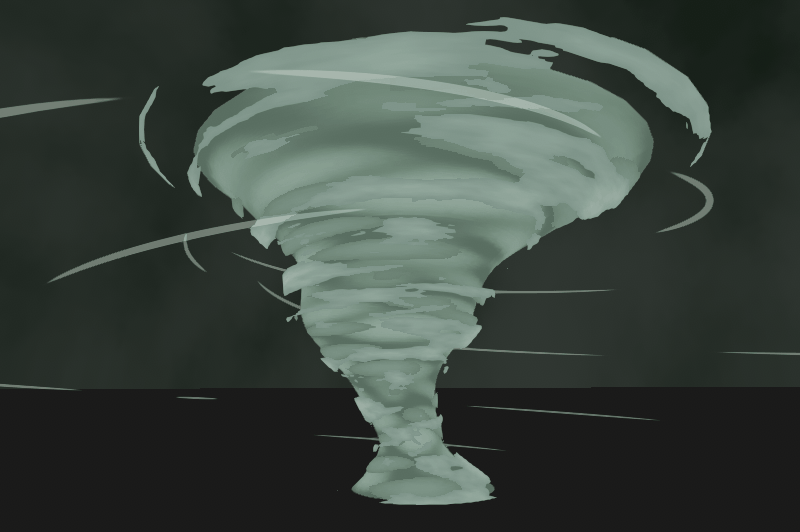
A shader applied to a few layers of alpha-clipped scrolling noise, with vertex displacement to make it wobble
This is how it looks. Is there an easy way to get rid of the obviously tiling texture (I think its quite visible on the grey thing). I could multiply it with another noise texture maybe which has a different tiling?

Hmm allthough now that I am thinking about it, the displacement texture is not tiling at the same speed already, so it could take care of this. But maybe the displacement also is not enough to make this effect not visible
Also here its quite visible. I am trying to replicate the rightmost effect of the left gif.
. If anyone knows what I am doing wrong in copying (his looks much better), and specifically why its not so obvious that his one is tiling, that would help me a lot!


Hey Peepz Im trying to Vertex display from uv space, basicly scroll a texture over uv space and move it up by the black and white value of the shader, in the image you see the gradient scrolls up and down.
Now I just want to vertex to go up and down according to the values of that map In UV space. I use Unreal a lot for vfx, and in there this would be easy as pie what am I missing?

you want to displace the vertex based on the black-white amount in the texture?
i managed to do a sphere fading using sphere mask, but how would i do for a rectangle ?
Im new to vfx and shaders and i keep running into this error.
Shader error in '[System 1]Initialize Particle': undeclared identifier 'GetWorldToObjectMatrix' at kernel CSMain at Packages/com.unity.visualeffectgraph/Shaders/VFXCommon.hlsl(78) (on d3d11)
i Have zero clue on how to fix it
hi everybody: my editor log contains errors of this type: Protocol error - failed to read magic number (error -2147483644, data transferred 0/4) Platform: d3d11. Seems to be related to shader compiler. Does anybody know how to solve this? thanks!
Im having a problem with a sprite outline shader im trying to make, i just need the shader to get any black pixel in the sprite and replace it with a white color, but the shader is affecting the sprites wireframe as well and colors the entire wireframe instead is there a way to make it only affect the texture?


Hi All!
I've been trying for so long now to make a circle surface shader on my terrain
However just learnt that the reason my material was pink was because urp doesn't support surface shaders!
How do I convert this to a shader graph?!

:((((
Yeah But I need it done not in object or world space but dependent on the meshes uv
So I'm trying to replicate the style of Cult of the Lamb. Aka, 2D sprites in a 3D world, reactive to 3D lighting and shadows.

What is the preferred set up for this? Opaque shader with alpha clip? Transparent shader with alpha clip? Something else?
Currently I have a transparent shader with alpha clipping, but this causes sorting issues as the camera pans across the screen if the sprites are close together.
I tried making the shader opaque, which as you would expect, fixed a lot of the sorting issues, but my sprite-based characters/props are composed of multiple segments.

I was initially using Sorting Groups to handle this layering, but those don't seem to work with opaque shadrs.
trying to have normal map tile with the simple triplanar texture tiling but it seems to be applying to the whole object instead of matching the tiles. Any ideas how to do this properly?

Easy, I'm making one too haha! Use tarodev's tutorial on sprite shadows.
He gives you a shader
Mind linking?

Casting shadows from your sprites is as simple as pie. For some reason, Unity hides this by default, but I'm here to abuse the system and show you how to turn it on.
URP Shader link: https://bit.ly/34c0ttF
Original source: https://hananon.com/how-to-make-2d-sprite-cast-and-receive-shadow-in-3d-world-using-unity-shader-graph/
❤️ Become a Taro...
This?
It's a simple google search which can be done by yourself if you had the commitment to type what i just typed in
Unfortunately this is almost exactly what I had already, and doesn't solve the issues I've listed with sorting.
it works for me
Ah use pivot point sprite rendering

Try using pivot
By default for sprites is the center point not the same as the pivot point?
definitely looks a lot better like that, any idea why that big shadow might still be present?

instead of with the tiles
Does anyone have an answer to this?
here is with the transform node deleted
How can i get rid of these seams on my icosphere?


There are caused probably by the UV (or normal) seams.
I don't see anything in the graph itself that could justify the seam though, ..
Maybe some precision issue, if you are using a very high "height" value ?
Or double check the model to be sure the position and normal at those edges match proerly between the split vertices ?
Turned the model's normals to "Calculate" and there are no more seams.
Does anyone know how the vector here is transformed to a half?
half test = tex2D(_SliceGuide, IN.uv_MainTex).rgb - _SliceAmount;
what will be the left hands side value?
Only the X (red) value of the vector will be kept
thank you!
weird that the .rgb is then specified explicitely instead of just doing .r
Well, you're the one writing the code, up to you to only keep .r 😄
Haha yeah no I was copying from a tutorial and now wondered if there is a reason for him doing it like that
But yes I will use this newly acquired knowledge on my quest to write the best shader code jetbrains rider has ever laid eyes upon
Is there anyway to sample the URP colour buffer from a custom node in a shader graph? I'm trying to implement the Discrete Fourier Transform as a full screen shader but in order to do it efficiently it needs to be implemented as a multi pass shader.
Computing the DFT requires for loops to sample the image at specific XY coordinates and as far as I can tell that's not possible in shader graph. I found the undocumented function used for getting the buffer used for the scene color node but I need to be able to access the output from the last shader, which in shader graph is done via the URP sample buffer node.
Alternatively if anyone has any documentation for writing a full screen shader in HLSL that would be a viable alternative for me but from what I can tell Unity wants people to move away from that in favor of shader graph
Is it common to implement custom lighting in voxel games? What is the benefit?
Suppose there is just one directional light.
By implementing custom lighting, we can control the intensity based on voxel types, it can pass or not and so on?
Because all voxels are rendered with opaque shader
Lets say I want to draw lines every meter. Normally I use modulo and add a large value to the position to ensure it nevers goes in the negative range.
What would be a better implementation?
Use absolute value ?
@amber saffron Hah I'll see myself out. Thank you
Using Shadergraph, Lit, URP. Why does my roughness values have a sort of border/outline when the roughness map is clamped with high contrast?

the alpha value of the full white areas of the texture is responsible for that
you can just reduces the brightness of the roughness map.. so that the whitish border parts have lower white strength
the less white on the roughness texture, the less darkness on the tile object
@compact reef I don't think that's true, it should be able to deal with full whites in the roughness. I lowered them as a test and still have the borders


https://marmoset.co/posts/pbr-texture-conversion/ see Metalness Workflow vs Specular Workflow
I forget whether it's a problem with the specular workflow in Unity too, but either way it's a painful issue with content
https://creativecloud.adobe.com/learn/substance-3d-designer/web/the-pbr-guide-part-2 also goes into it a bit
For some reason The Mesh Effect i made wont add the rest of the gradients and effects
compute-shaders: well my HLSL chip8 emulator finally starting to do some more things after being stuck on things for months. still don't get why the fix i found in CPP for the biggest flaw still doesn't work but progress is progress. (using unity to set vram and export the render to project the rendertexture on a model) https://i.gyazo.com/fd24e9eaf2c2542cb5c81a605b0c67ba.mp4
also all roms are loaded in as textures. so the cpu is only used to init things nothing more. it will probably need to export sound at some point based on texture/DMA or sum to wav and input to texture but eh. small details, i similarly had to add a timer anyway for clockcylces. so it has a custom fps inside the shader.
[numthreads(10,1,2)]
void CSMain(uint3 id : SV_DispatchThreadID, uint threadIndex : SV_GroupIndex, uint3 threadid : SV_GroupThreadID)
{
    if (threadid.z == 0)
    {
        ProcessCPU(id, threadid);
    }
    else if (threadid.z == 1)
    {
        ProcessDisplayRendering(id);
    }
};```

forcing a target speed of 10fps on the emulator while the game runs normal around 144fps https://i.gyazo.com/7170a30158db7c3322fdbad167cd6539.mp4
I can't seem to get the effects to work on the material.
Hi guys! i'm trying to make a Shader to draw points in the scene. This is what i got but it is not working.
This is the code https://gdl.space/ocahunebek.cs with the shader and cs script to load the point to show.
Hi all 👋! Is it possible to enable POM Shadows under URP ? Thanks
@wary bolt what kind of points can you show an example
I want to make something like this

From a vector3 to a "3D points"
I'm trying to render a Point Cloud
Oh nice!
Camt help sorry. All I can think of are already made components to render point clouds and or gaussian splat
What component?
could be filtering, try using point (no filter) to see if it makes any difference

GitHub
Point cloud importer & renderer for Unity. Contribute to keijiro/Pcx development by creating an account on GitHub.

Learn how to use the Unity VFX Graph to create a Point Cloud Renderer.
if you're having issues following along here's the C# script I wrote: https://pastebin.com/SaiTrQ0k
And here is a git repo for unity 2022: https://github.com/Renge-Games/UnityPointCloudTutorial
Sick of downloading assets one by one into a new project? Get my free package As...
Good point, I noticed my shader says smoothness instead of roughness. The anwser isn't to invert, the order is correct (i.e white = matte, black= reflective) so I wonder if I have the wrong shader?

I set the data map (RGBA that contains roughness map) to Point-NoFilter, didn't change anything.
How about 'stepping' the metalic and smoothness input?
@tacit parcel Not used stepping before, like this? What would you suggest for values?

I usually start with 0.5
I dont use shadergraph often, but seems like you need to connect the sample output to In and 0.5 to edge
Ah much better, think you're onto something. Wondering if the pixels come from the texture (2048x2048) or something else.


switching back to bilinear from point filter helped, oh and I can play with edge values. Ok I think I got this now, thanks so much @tacit parcel been trying to figure this out for a while!

anyone ever succeeded in rendering Parallax occlusion mapping shadows under URP?
To work, this would need either to :
- use a custom POM node to also consider light, and so, custom lighting
- Modify the generated code to add depth offset to the fragment output (this was something done in the japanese garden sample at some point)
- Wait for URP to implement depth offset in the lit stack
Hello, is there a significant difference about how unity handles shaders in built in vs SRPs?
I had some shadergraphs in HDRP that used some position randomization to be able to reutilize a materiala cross multiple objects
it worked pretty well, but here in SRP the randomization still works but for some reason is applied to all objects, so it doesnt really work
oh nvm, I think I am not randomizing my vertex distortion, one sec
yup yup, my bad
what comes in the Shader Graph slot? I got some that wont get in there but they are shader graphs. Do only specifc ones go in there?

Grettings Friends. I have a ShaderGraph I made, that does exactly what I want, except only on static objects. For non-static objects, the object is rendered at 0,0,0, and its scale is reset to 1,1,1. What's up with that? This is the graph.

how to reverse a VFX?

how do i make emission float use the same color as the variable above but only control the intensity of it
i tried this but it doesnt have inputs

Multiply the Color and Emission properties
Should be a "Support VFX Graph" tickbox in the Graph Settings to enable graphs to be used there. https://docs.unity3d.com/Packages/com.unity.visualeffectgraph@16.0/manual/sg-working-with.html
Or for older versions, you'd add VFX Graph as one of the Active Targets.
Should i be concerned with this error text?
'MetaVertexPosition': implicit truncation of vector type
Compiling Fragment program with UNITY_PASS_META
Platform defines: UNITY_ENABLE_REFLECTION_BUFFERS UNITY_USE_DITHER_MASK_FOR_ALPHABLENDED_SHADOWS UNITY_PBS_USE_BRDF1 UNITY_SPECCUBE_BOX_PROJECTION UNITY_SPECCUBE_BLENDING UNITY_ENABLE_DETAIL_NORMALMAP SHADER_API_DESKTOP UNITY_LIGHT_PROBE_PROXY_VOLUME UNITY_LIGHTMAP_RGBM_ENCODING
did you enable "always refresh" in the effect toogle windows

You have more properties in the blackboard that don't appear in the Material (e.g. the GradientNoiseX and Mask ones). I assume you may have unticked "exposed" on these, but this may not do what you are expecting - Unexposed properties can only be set through C# using Shader.SetGlobalX functions, otherwise will default to 0.
Should keep properties exposed unless you need them to be global.
Yea i have that enabled, but it seems like it won't load in the gradients and the other effects when i turn it into a material
I checked out the properties, all of them does has exposed ticked
Part me think may be an issue with one of the vectors
Are you using a custom Shader GUI to hide the properties then? Maybe remove that and check the values?
Or maybe you have multiple versions of the shadergraph file and are creating materials from the wrong one?
It doesn't make sense the properties don't match the material unless it's one of those.
Maybe share the shader in a unity package so we could check it
gotcha
Gauntlet
Having a bizarre issue with shaders right now. I have some models that use 2 materials, one as a base and oneto sue with a trim sheet

my issue is, if I set the trim shit material to be unlit, it works as expected
but if I set it to be an opaque material instead it just dies
(when using a shadergraph)
I cant get it to crash right now but if I use this material or any other shadergraph material
then it starts spasming out and the texture seems to start appearing mid air
Super lost here, I am not doing anything at all on the graph
literally just setting its color to red
shadergraph lit works fine for everything else, just not these specific model setup
might be some z fighting issues?
Anyone used polybrush for painting? Is it seriously buggy because I find it works and then doesn't. I'm just trying to blend between two colors. My setup is simple.

Yet nothing happens when I paint in red. I get a warning message that keeps vanishing and then re-appearing, it says my material is not set up for VC but it is. I just want to be able to paint green in.

I don't think the issue is polybrush however, if I directly hookup my VC into the basecolor it's going what it's supposed to. Leads me to believe the problem is more in the shadergraph?

yeah no shadergraphs to some extents are completely borked up
in built in
I used a triplanar node on a shadergraph, which was working perfectly, then i used a triplanar node inside chadergraph, which completely broke the material forever
absurd
now for that specific model, every single instance of a shadergraph used on it will not work on it
I have no idea how to fix this lol
like, i have no changes in my git
I restarted my project, discarded all my changes and even went back to an earlier commit
but the shadergraph is still eternally broken for that mesh
this makes absolutely 0 sense
Is there any way to compute the FFT of the colour buffer? I've been stumped on this for a while.
Something like this never happend, but i had some similar problem when changing material. I was changing shader like you were doing and it made a mess. What helped me was changin material directily in the Mesh render component. Also i think you are having problem because you are using prefab and maybe somehow it s not updating.Another thing , you probably already know you should use one material per object, otherwise it has impacts on drawcall. I dont know if the scene is heavy. So probably you should plan the shader in a different way. To be honest i really dont know what is the problem, so mine are just suggestions to try. sorry
Dont worry thanks for the help
I ended just making a new material
and replacing it via script
I have no idea how I broke it so badly
but hey, on the plus side, I was able to get a nice water puddle
Pretty flexible too! now I just gotta make some decent masks hehe
hi, i am trying to use mask using custom shader but there's problem where it would block all of my 3d object, anyone know how to fix it?
Hey, would some good soul have nice object space triplanar node/custom function or graph that is not streching texture on it's object space y aligned surfaces?


Have you tried with a plane instead of a cube? A cube has all 6 faces with the normals pointing outward.
hi, this was using quad

Maybe check back face culling in the shader
Is that a custom shader with shader code or ?
yup, it's shader code
Shader "Custom/Mask"
{
SubShader
{
Tags { "Queue"="Geometry+1" }
    Pass {
            Blend Zero One
            //ZWrite Off
            Cull Front

    }

}
}
using cull back still have the same issue
but when using cull Front all the object is rendered


my first idea was using stencil buffer but when player looking at specific angle it will reveal the object that i want to hide
Have you tried ZWrite On?
yup, nothing changed
i think using masking shader was not a right choice
any ideas whats going on with this material? I have shadows completely disabled in URP settings. And the shader has cast/receive shadows disabled.
Hi. I added a depth effect to my materials. In the 3d program (Blender), everything shows perfectly (in the render mode: Material and in the Eevee render. In Unity itself, I don't show these materials very much... How to do the same as in Blender?


Correct way to do this? I want to just combine a texture with a fresnel effect. (2D sprite lit graph)

Hey, I want to create this water effect can someone help me. My simple game idea is that we will control a water drop or a patch of water then we will collect water.
Image

How do I make a 2D puddle for a dungeon crawler? I can't make the reflection direction well, since if I rotate 180 degrees so the reflection looks good, when the player goes down, the reflection goes up instead of also going down with the player. How do I fix this?
This is the shader:


What do you mean a depth effect? Can you be more specific?
It depends on the result. the last node can be a ADD or MULTIPLY node. IF you want a kinda glow effect i'd say to use add.
yeah: no matter what i do, sprite appears black. if i plug the texture straight in it does show up though
is this something to do with 2d?
Yes of course it appears black, because you have the center of the fresnel dark. Now dark in value is 0. So if you multiply a value from the texture you 0, hence black.
What's the way to achieve the intended effect?
Can't really see what's going on in the shader; there might be a Reflect node, if not, the reflected vector is r = v + 2n*dot(v, n) where n is the normal vector and v is the view direction
There is no Reflect node. Should there be?
There's an option to make specular reflection not depend on alpha; you'll want that and for the top one it looks like there's just some constant grey base color. It might be that you'd need to do sky reflections manually or all reflections manually to get the style perfect but that's not too much of a pain
Iirc it's in GLSL but might not be in HLSL (or just Shadergraph). Either way you can calculate it as in my message so that's fine
Sorry but I'm really inexperienced with Shader graphs. Could you please tell me how to use the formula you gave me?
You want to calculate the vector you're looking along for the reflected image right?
just to make sure
wait you're doing a 2d game actually then you don't need to do normals and stuff
you'll want to switch the sign on the y coordinate of the reflection
you want the reflection to follow the player in x, but go in the opposite direction in y
I want the texture image on the model to be the same as in Blender.


Thank you bro I will try it and get back to you asap
Did you put your normal map in the right place ?
you need a normal map. 1 note: your normal map looks pixelated, and i think you baked the texture with shade flat on in blender. I don't know if that's the look you were looking
normal map + maybe parallax as well
I switched to the normal map, and as a result everything turned red...

You need a separate normal map texture for the material
anyone here know why the normal texture become less visible when i am far away?
That's mip-mapping, check the texture import settings:
- you can set "Filter Mode" to"Trilinear" to have a better fade between mips
- you can increase the "Aniso" Level to make the fade further away
thanks, it fixed, i just disable the generate mipmap
Not a "great" fix, but yeah, it fixes it.
I made a skybox shader but now all objects in my scene leave a weird afterimage trail behind. why is this the case and how do I fix it?

I guess it has alpha below 1 so it's partially transparent so the uninitialized void creeps through
the skybox?
Yes
So im trying to make a custom shader with really specific features
The shader is for a particle so that:
- Red and Blue channel are uv coordiantes
- Green channel is the height position in the space of 0,1 and blended to grab always the minimum of all the ones rendered in screen
- Alpha channel is a strenght parameter that is like a smoothed out circle (1 in the center, 0 on the edges of the circle) blended as a Max operation
i got all of that sorted out with three passes right now (could probably simplify to two)
However I want to add nother condition. Red and Blue channel should only write if the new alpha on that pixel is bigger than the alpha that currently exists on that one pixel
I feel like there is a way to do that with BlendOp, Color Mask and Blend keywords (like I've been doing until now) but I cannot figure it out
Here's the shader, you will see that altough long, the fragment shaders are extremely short with what I said
Ideas?
If I just put blend op max on the RB pass, im getting that, obviously its only getting the max value, so 1,1
I'm curious what that's for
an option would be to clip the RB channel by the alpha- existing alpha value, but I dont think I can get the alpha value on screen on the shader
It's for a 3d displacement shader for grass that works with a single 2d texture and a particle system. So this shader allows for the spawned particles to inform, direction to how to displace the grass, up to which height should it start displacing and how much should it be displaced. the particle system is set anywhere you want to displace and then an ortographic camera captures that data and creates a render texture for the grass to sample from
By adding that new condition I can add a fake direction of the particle system effect on static particles that would allow for grass to stay as the first time the particle is spawned until a new particle is set on top
(the particles never move, so they have 0 velocity) (but with that the end result of the render target would give the effect)
This is how its looking rn, which is nice, i just want to add that extra blend to allow for the grass to stay down to the original moment

Any idea to apply that condition?
Ah, that image sheds some light
Not sure if your particle shader can "wipe" the texture over time, as the particles are gone already and 0 alpha can't overwrite anything on the render texture
Or so I assume
If you had some "neutral" color, you could blend the render texture towards that a bit each frame
OKay so I do blend to 0 alpha, which gives 0 strenght and it doesn't apply anything, but the direction doesn't have any neutral value
The idea would be that if the existing alpha value on screen is less than the one that im trying to write, to apply the new red and blue, otherwise, keep the older one
(by using the particle system, I also added an alpha multiplier and a size over time which makes them disappear over time)
Ah, of course you're not using the trailing effect of an uninitialized camera
No if you don't have to, fading the particles directly is better, I just forgot you had the option
ah okay 😄
I think what you're asking requires the use of GrabPass, which I'm not familiar with
With that even if the particles share the render queue you probably are able to read the color of the particles below before drawing a new one
Actually nvm! Seems that if I change the sort mode to Oldest In Front it gives me the desired effect
ah no, it does give the effect, but not exactly as I wanted
I will take a look at grab pass
OKay so I just checked and it seems that the grab pass is returning a texture with the alpha to 0?, or maybe im doing it wrong
yeah nop, because of the render queue, it seems that i don't really get a value of anything written before that pass, and since i need to get the red channel of the previous pass to write the next red channel, and i have the grab pass before the red channel, i dont get any red channel data on the pass
I think this is for #archived-hdrp
And what node do I use to do that?
you can negate the y component and then vector2 them back together or you can just multiply by (1, -1)
So any ways, I couldn't get it working, no idea what Could I dO?
None of the TMPro shaders are SRP Batcher compaitble, does that sound right?
I wonder if theres a way to get a reduced version of the shader, I dont require any UV scrolling or any fancy stuff, I just need to translate and scale a bunch of world space TextMeshPro instances (non-UGUI)

Have you measured poor performance on TMP draw calls? You could write your own SRP Batcher compatible TMP shader, but there's no guarantee you'll notice any performance difference.
Fair enough, no I was just going by all the non-batched calls in the frame debugger
Do you have many different materials for text, or mostly using the same material? SRP Batcher mostly helps when you have many different materials using the same shader variant. But if you're using mostly the same material instance, then you will have fewer SetPass calls, which is usually the most expensive part of a draw call on the CPU.
Its 2-3 different materials at most
I think the Frame Debugger will still show it as separate draw calls, whether they each have their own SetPass call or not. You could try having the Stats window in Game View open and see how the SetPass number changes if you disable all the TMP text.
Im also scaling the transform over time (think in-world damage numbers), which is invoking some SDF rebuilding stuff which is probably more costly than the draw calls
good call, Ill try that
Are you using 3D text or UI text?
3D text
Thanks!
Like this? It still doesn't work 😭
ah i see the goal; can you show the whole graph?
if you change the tiling back to (1,1) and swap the arguments in the remap to (0.02, 0)?
This is the main preview instead of the player character

nvm fixed it now it's this

but it's not flipped
How do I get light attenuation factors for point lights in the ForwardBase pass? I tried using (unity_4LightAtten0) as the docs describe in (https://docs.unity3d.com/Manual/SL-UnityShaderVariables.html), but it does not seem to work, it does not seem to supply it with any meaningful value
I'm trying to make a shader graph that lets me change the transparency of a particle system over time. Since I'm wanting to use HDR colors, I figured I needed to use a shader to control the transparency over its life time but I'm having trouble getting it to work and can't figure out what I'm not thinking about.

Hi, folks, is there a fast way to make an outline of an object in frag shader?
I'm working on a old shader of mine (in URP) and got some errors, did these got renamed?

Are there errors in Unity?
Yeah, this. If it is too hard to fix, I'll just backup the project and update the plugin, for some reason updating it is removing some setups I made on the materials so I wanted to solve the error :((

the project is from 2020 so URP probably changed a lot
and the plugin as well lol
That error doesn't have to do with something being missing, that has to do with something being declared twice
also, you'll need to select the shader and look at the errors in the Inspector to show them consistently, as shader errors can be cleared from the console
Oh, I found the double definitions lol now it works, although unfortunately I'm having a weird issue with my project
for some reason every custom shader I use flickers the whole screen as some sort of depth view

it flickers very fast and I'm not sure whats causing this, a lot of shaders are doing this
So Im trying to re-create the Specular AA from this presentation https://media.steampowered.com/apps/valve/2015/Alex_Vlachos_Advanced_VR_Rendering_GDC2015.pdf in URP. How do I do normal centroid sampling in shadergraph ?
Since it's an interpolator modifier, you can't add it to a Shader Graph shader.
Im trying to figure out what it does under the hood so I can replicate the behaviour
That should be at least possible
Hey everyone, I have a little trouble with Shader Graph. I want to create a smooth transition between black and transition using Node SmoothStep. I'm also using UV node to give direction of this transition. But I've realised that now I can only apply transition from left-right or up-down. Is there a way to create transition from down-left corner to right-up corner of a object?


You can add R and G to get a gradient from bottom left to top right
One minus before adding R to flip horizontally, before G to flip vertically
Or use Rotate node instead of / in addition to UV for a free rotation
THERE IS ROTATE NODE
OW SHIT
I LOVE YOU DUDE

THIS IS AWESOME
@grizzled bolt I've done what you said with Rotate but I can't be connected to other panels


What's the expected result?
That I will connect three planes, and they will hide top of the walls
But the problem is with intersection of two walls
Seems like something you'd fix with mesh UVs and corner pieces

It should be more linear effect
Could you descibe it for me?
Cause to be honest I'm pretty nooby in this subject
You can't overlap the parts and expect the parts not to overlap
So you probably want a corner piece with UVs for the gradient like this

discord CDN might not be working right now
Yeah... I've tried to send image to my friend and it still loading
It's not overlapping anything
There are 3 distinct planes
One for left part
One for corner
And one for right part
Ah, my mistake
And I though that I could use a Rotate, rotate UV for 45 degree and that get the effect
But as you see border have different color
So it's as linear and clear as I hoped
If streaming is working then we could call to each other and I could share my screen
If it's working
Not like sending images
Cause it's still loading for me
XD
I guess you could use the Remap node to change the corner piece from 0 to 1 range to 0 to 2
But that seems maybe like bit of a waste to do it with multiple shaders when you can do it with one by utilizing mesh UVs
I mean creating new UVs specily designed to deal with this problem?
Or some kind of node in Shader?
UVs are mesh data that (primarily) determine how a texture is mapped onto the mesh
You're reading that data when using the UV node
(URP) 2D Animation Reimagined
That I understand. But what you are suggesting is creating new model with special uv to deal with this problem?
Or is there any way to deal with this using shader
Cause to level building I'm using ProBuilder
And this could potencialy mean each corner in my map would take more time to deal with
Am suggesting that and yes can also be dealt with a shader like I said using the remap node
I wanna use remap node. But how XD. After the rotation or before?
Should work in any place but I'd put it after the rotations
I imported a psb file into Unity with the PSD importer package, with the settings Individual Sprites (Mosaic), so that the various layers are separated. The default material, Sprite-Lit-Default works perfectly fine. However, when I tried to make a custom material for a custom shader graph, it first says that the _MainTex is missing. I added the _MainTex reference, and next I have to fill in the Texture, and I chose the thing I imported from earlier. The _MainTex is linked to the Texture(T2) field of a Sample Texture 2D node, and the RGBA is then linked to the Fragment's Base Color(3). The end result is a really messed up sprite. I am guessing each layer in the image is looking at the entirety of the thing I imported, instead of the specific area which concerns it. Am I missing something? Is there a better way to go about this?
Wild guess you have not linked Sample Texture node's alpha output into the final alpha input, and you're seeing the sprite without alpha applied
But another weird thing you're likely seeing is the whole raw psd texture
When you import a PSD, the texture itself is a jumbled mess but the importer compiles it into neatly sliced sprites like it was in your image editor
Shaders don't see it that way, but it doesn't really matter
When you use the _MainTex property, that gets data from the Sprite Renderer component to display the correct sprite slice
I was actually missing the alpha output, so I added that in, but currently the final sprite just looks grey:
The non-grey part uses the sprite lit default material, the grey parts are the layers which are using my custom material.
I restarted the Unity editor, and now it's no longer grey, and back to messed up:
AH I think I got it. I had to click on Fragment, then Graph Settings, Universal > Material, and select one of the Sprite options.
Which I expect means you were using the 2D renderer?
That one attempts to disable all non-sprite shaders
Out of spite, likely
Yep
Makes sense. Is there a go to documentation page for these kinds of things? The ones I found have scattered pieces of information, but doesn't have the nuances like the relationship between 2d sprite renderer and the shader graphs
No, just scattered stuff as far as I know
Trialing and erroring for a couple of years helps though
I have an idea for a shader but I have no clue where to begin with tackling this idea
basically I want to check what UV coordinates fall within 2 functions I made and if they do, I want to color that part white while leaving the rest black so I can use the output to put into the alpha and multiply it with a color to put in the color.
this is the function, b is only there to move it from [0,0] to [0.5,0.5] to map it for UV's

in the graph it looks correct but when I put it on a quad it doesn't work. anyone know what's wrong?

nvm made it work
Hello, i made a Rainbow Scroll Effect for ui image components.
Everything works, it uses the alpha properly and the scroll effect looks to my liking and the scene mode shows the same working thing, but in game it always shows weird dark red where it is supposed to be transparent.


Unity 2023.2 has a "Canvas Graph" type which would fix this. Older versions don't properly support UI, but switching the Canvas component to ScreenSpace-Camera (instead of Screenspace-Overlay) is a workaround
Working on a custom shader graph. I have an object, consisting of different kinds of identicla mesh modules that have already been joined into one object fbx in blender. I want to build a shader that takes these individual modules in the mesh (sub-meshes) and assigns each one a different texture, randomly. how can i get access to information about the "mesh islands" within my parent fbx in the shader?
So my question: How to select between different textures in shader graph URP, depending on which mesh in the joined final fbx is concerende
Hi guys, I'm new to this part of game dev and wanted to know if what I intend to do is possible and how would you do it.
I'm creating a 2d procedural Galaxy and I have a 2d plane tiled with voronoi, each tile has a terrain type (void, Galaxy arm, nebula, etc).
I now need to draw each tile and was thinking of using a shader to blend textures and make tile transition smooth, taking into consideration the neighbor tiles.
Is this possible?
I'm using urp
Submeshes have their own materials independently, which means you can give them whatever materials and material properties including texture via scripts
It's not apparent why you would need to do it in one shader instead of multiple materials, but in that case you need some different way to pass the information about the island to the shader such as uv coordinates or vertex colors
ok thanks i upgraded unity and it works now, thanks
Anybody?
Anything is possible more or less
But shaders alone don't really have knowledge of what's around the pixel they're working on so you usually need something else also
Ok cool, good to know. Thanks!
Yeah I guess I'll need to set the shader textures for each tile.
But as your said, I don't know if the shader can know if the pixel is near the center or the edge
Often UV coordinates, vertex colors or additional texture maps are used to convey that information to the shader
i made an intersection, how do i make it noisy though? so it looks a bit more interesting than just a line?

Ok thank you very much!
@grizzled bolt hello I am a noob at unity and I am learning basic material and texturing
whenever I apply a normal map to a texture I fount on the asset store, its colors are all weird.

It looks like this on Default

Please don't ping those uninvolved, or crosspost
Seems like you got an answer already
no can do mini mod
!warn 1146591321801379961 In that case, don't ping people into your question, it's obnoxious.
 lilmoonly has been warned.
lol


Is the shader on a Canvas component? You may need a Canvas Graph in that case
#archived-shaders message
sadly this is on unity 2021
is there any otherway?
One way would be use sprites instead of UI & Canvas. Otherwise see #archived-shaders message
There may be some unofficial Canvas Shader Graph examples but I never looked into those
I created a tractor beam using a 3d model and a moving texture shader, but for some reason on the seem and on the seem only the texture doesn't overlap properly, I know this is an issue with the shader somewhere because when I remove transparency or dual sided rendering it look fine, anyone have idea's what it could be? or how to fix it


on the inside it also matches up btw, just looks funky when transparency is applied


I'd probably keep the shader single sided, but include both sides in the mesh itself (duplicate cylinder, flip normals and join objects). Somewhat similar to the "Pre-sorting Mesh Triangle Order" example here - https://www.cyanilux.com/faq/#transparent-sorting
Bit messier, but an alternative is splitting it into two objects. Enable the "Allow Material Override" in the Graph Settings, then can have two materials (one rendering Front faces, another rendering Back). That way you can also force the render order with the Render Queue / Sorting Priority on each material.
Hi everyone, I'm making a transparent alpha noise shader for VFX and I ran into this problem with Bloom. When Bloom is turned on, the parts that are transparent (using a mask texture) have these bloom artifacts that goes in and out similar to what happens when you have bloom on a really reflective material.

What could be the cause of this and how do you fix it?
The first thing I'd try is a Saturate (or Max with 0) in the shader, to remove any negative alpha values
HI. Question. I have a normal texture for a material albedo, and a mask texture of black and white. I'm trying to use the mask on the same material but it's not working out as planned. The black is what will disappear (ignore the clipping for now. the model still in development)
Am I using the wrong shader/ settings for this?


Hi guys ! Can someone explain me something ? Here my problem : I would like to create a pixel art animation of a teleporter that I could put on any sprite, any size, and any shape without it being stretched or distorted...
I already got my spritesheet ready, and cut on Unity, but when I try to import it on a texture material, I simply can't, most options in the inspector are grey-ed, I can't interact with them... I already selected, in the texture type, "sprite/default"... Any idea ? I don't know how to proceed, since I don't know much about these things...
I know it got suggested to me to use the shaders thing, but again, I know nothing about it, and tutorials didn't help me much...
I upgraded from Unity 21 to 22 and now my polybrush tool doesn't work anymore. Can anyone help?

its in urp
https://paste.ofcode.org/35aY9ACXbyXSUuafN5x2FMM
This code is supposed to change a shader material values over time and it works for the mesh renderer component but i also want to use it on a skinned mesh renderer and don't know how to do it. Can someone tell me how you can do this.
From a glance it should work on a skinned renderer as well since you are getting the base renderer component type
One problem could be that the material you want to disolve is not the first material on the skinned renderer
Anyone know if its possible or if there is a tutorial somehwhere to turn the cone into like a line of sight cone with a shader? So that it doesnt render the parts blocked by geometry from the capsules positions?

You would need to create a mask for the code. This can be in the for of a one dimensional depth map rendered from the point of view of the capsule.
You obviously understand that a million times better than me 🙂 Is there somewhere I can read up and learn how to do that?
Some line of sight effect tutorial probably exist around, but I don't have any in mind right now.
Hello!
I'm making a BIRP surface shader with custom lighting.
It should let me pick a colour for the shadows.
It works fine for directional lights but point lights produce this strange square-like artifact.
Does anyone know what could be the cause of this?

just wondering, if i create for example a kelp model in blender, can i then move the leaves using shader graphs with sine wave and so on in Unity?
Sure
Hey, I'm a mainly a programmer and only recently am I learning about the rendering pipelines more in depth so...
are surface shaders... used? I vaguely remember either reading something or someone telling me that it's a rather legacy system
How does one get the shader graphs to work?
and that they are "basic", i.e. only relevant when you don't need anything fancy
you should be more precise in that question
Surface shaders can only be used in the Built-in RP, but yeah they're the standard way to write a shader affected by lighting.
If using URP, HDRP, it's recommended to use a Lit Shader Graph instead
Sorry, how do I get the shader graphs to install correctly, or be able to be used
@broken sinew Unity wants you to think of anything exclusive to BiRP as legacy, so make of that what you will
yeah, I read so much about how URP/HDRP/SRP are underdeveloped/lacking/incompativle that for now I am solely focusing on BiRP
Those criticisms don't apply much in the current year
huh, good to know. Are SRP/HDRP used now more then BiRP? or is the BiRP still the mainstream choice?

People using Unity, what Render Pipeline are you using most?
💖 12 🔁 1
Doesn't embed but this poll shows URP is likely the most popular now
It was for a long time even when it was losing to BiRP in graphical features, due to the easy to use tools and out of the box functionality
HDRP has been a well polished and feature rich render pipeline for years, but it's overkill for most projects and takes some learning to get into so it's not used a lot
interesting! Before seeing that I was under the impression that it was still BiRP that was the most used one! (it was magnified by remembering how the feature comparison table looked like)
BiRP still has its niche since it has so many resources made for it over the decade, and currently expanding its rendering capabilities seems easier than expanding URP
hmm, this made me remember an issue from a while ago — does URP have some easy way of sharing data between passes? e.g. first pass renders something in a much lower quality as a "precompute" step (e.g. to implement cone tracing) and the second one reads from that buffer?
Practical usage of that would be for example writing a single shader for gaussian blur
That I don't really know about
There might be a way but it's hard to find resources, so it's the kind of thing that falls in the "expanding capabilities" category
The way SRPs work with passes is kind of unique to them
Looks like you are treating the light distance attenuation as shadow, when it should just be a "mask".
The red artifact you see is the light "range"
I'm pretty sure the rendergraph implementation coming with unity 6 does exactly that
(finally lol)
huh, where can I find any info about unity 6 ?
I've only recently started using ShaderGraph. Found some bugs using it in Builtin, so switched to URP.
But, I guess I still don't understand something. Why does my shader cause some objects not to render if I view them from certain angles?
I have two example videos here. Looking at the gameobject from one angle, causes the particle system to get 'cut off' by I guess the floor?
But, if I rotate my camera around the gameobject 180 degrees, it renders how it should.
Does anyone have any glow shaders instead of Post Processing for mobile?
glow can only be achieved by using post processing
you can use custom bloom either by creating it by yourself or buy mobile post processing in the asset store
or you can use fake billboard if your obj is not too complex
I've checked the asset store and they all seem to have poor reviews
Could you explain this futher, this is my object

https://assetstore.unity.com/packages/vfx/shaders/fullscreen-camera-effects/fast-bloom-mobile-urp-vr-ar-default-pipeline-135229
this one is not that bad, or you can try it before you buy, just search it on the internet for free then buy it if you like it,since unity refund policy is not that great

Add depth to your project with Fast Bloom ( Mobile , URP , VR , AR , Default Pipeline ) asset from Rufat's ShaderLab. Find this & more VFX options on the Unity Asset Store.
basically you create lens flare
thought it's very time consuming and if you put too many "fake bloom" in one scene then the performance will drop
right. is this really the only options, i've been stuck for weeks trying to get it not ruin my mobile game
do you know any trsuted sites for the free version to test
A bit tactless to ask for an asset piracy site on a channel where the type of people who make these kinds of assets hang out, don't you think
Is there a way to attach a heigh map to a shaderGraph?, cause I have not found out how
Heightmaps are usually used in Parallax Mapping, there's a node for it - https://docs.unity3d.com/Packages/com.unity.shadergraph@14.0/manual/Parallax-Mapping-Node.html
It's used to alter the UV coordinates when sampling the other textures
But like where can I connect it? The main node doesn't have an input for heigh by default
You connect it to the other texture samples (e.g. the albedo, metallic and bump maps). e.g. Parallax Mapping Parallax UVs -> UV port on Sample Texture 2D
So I add the heighMap texture to the normal texure or...?
No, there is a Heightmap input port on the Parallax Mapping node
Yeah, and then where do I add the parallax mapping? To another texture you say? which of them?
All of them
Another way to use a height map is with tessellation displacement such as shown here https://youtu.be/ycJ434Lh21w?si=-dzER3txSXULljbU
In this shader tutorial, I show you how to use tessellation and displacement to create incredibly detailed meshes without paying for high polygon counts. I show how to adjust the tessellation so you get triangles right where you need them and remove them where they're not needed.
Here's last week's video on creating the specular highlights for ...
Hi guys have you any idea for shader of cloth tearing simulation , a bit like paper tearing
hey i'm asking here since resources on the internet about this are simply non existent. I'm trying to make volumetric clouds on HDRP and transparent objects work together, but could not find any way to do this. Does anyone have any idea ?
If the transparent objects are always in front of/behind the clouds, you can put the clouds into their own transparent object; otherwise you'll probably need to recalculate the clouds for every transparent object + the background
i use the HDRP clouds included in volumes, i cannot access their data, but anyway i discussed about this in the HDRP channel and a solution would be to use a custom skybox
You could probably render anything that is supposed to always be behind clouds straight into the sky, like in a custom pass right after the sky pass
this or use a second camera which exists in an empty world with only the sky writing to a render texture which is applied to the skybox
Hi! i have this shader https://gdl.space/oceduqehed.cs to draw points on screen. I Set position and colors and than i draw with Graphics.DrawProceduralNow(MeshTopology.Points, points.Length 1); How can i edit the code to draw Quad instead of Points?
If you're on HDRP (and in general) just never use second cameras. Writing custom render passes is a LOT more efficient
Unless you need wildly different perspective or rendering, you can do it better with a custom pass
for now the issue is at the bottom of my todo list, i'll look at custom passes when i get back to it
I am working on a custom lighting shader.
It works at runtime and in scene/game view, but the shader graph preview is bugged.
I use custom HLSL blocks. I expected the following code to only set the value to 1, but shader graph still calls the main shadow method. Can someone point me into the right direction on how to set this up properly?
void MainLightShadows_float (float3 WorldPos, out half ShadowAtten){

    #ifdef SHADERGRAPH_PREVIEW
        ShadowAtten = 1;
    #else
        ShadowAtten = GetMainShadow(WorldPos);
    #endif

}```

When opening the graph I get the error `Shader error in 'Master': undeclared identifier 'TransformWorldToShadowCoord' at Assets/DevDunkStudio/ShadowReceiverURP/Shaders/CustomLighting.hlsl(65) (on d3d11)`
This is from the GetMainShadow method.Is the GetMainShadow method also surrounded in a #ifdef SHADERGRAPH_PREVIEW block?
An old question again, Any suggestions/clue/link/help for implementing real time spot light/point light on a simple fragment shader which is also holding lightmap on the object at the same time?....tbh, it's been month i've been digging this matter
still havent come up with any solution
how do I customize main texture for shader graph for other sprites than player without having to make another shader graph?

Customize how ?
You've exposed the MainTex which makes it reusable on the material if that's what you mean
maybe you can loop through these arrays
source: https://docs.unity3d.com/2020.1/Documentation/Manual/SL-UnityShaderVariables.html


🤔 interesting, the lights are in view space position?
ty, i know these keywords, but i have poor knowledge on managing them to work along with lightmap
Thanks, that fixed it. Did not know this was needed before.
I know it's probably micro optimizing, but what would be faster in hlsl blocks on mobile (half fp supported)
if(half > 0) or if(half > half(0))
Would 0 be cast to an int, which can be optimized, or will 0 be a float (in which case half(0) would be faster)
Hi! I have a simple shader set to transparent mode for some of my environment pieces, as I need to fade them in and out, but now the grid in the editor draws above these objects, and it's quite confusing to look at. Is there a fix for this? I understand this might have to do with the depth not being calculated the same way with transparent shaders. You can even see shapes where the grid is hidden, these are non transparent objects

Is there a way to customize the Input texture using code I mean
im creating a Damage Flash and want to use character's default idle sprite as Main Texture
If you named the property reference "_MainTex", it should automatically take the texture assigned on the sprite
Is there a fix for this?
you can make/force the transparent object to write to zbuffer and also enable depth check. Shadergraph or shader code?
It's shadergraph so it has depth check but I'm not sure if I can set Z Buffer
it should be possible with shadergraph, but I forgot how 😅
yep, that should be the one. Not sure why it doesnt work though 🤔
Yeah that's strange.. It's fine I ended up swapping the material at runtime before the fade, so that I get all the opaque advantages while not faded
Thanks for your help though 🙂
No problem 🙂
Hi all. I have a transparent object that occludes another one. To do so, the occluder has a shader that has ZWrite On, ColorMask 0 and a render queue of 1999 (Geometry - 1). The occlusion works fine in the scene view, but in the game view, it looks black or any solid color i use in the camera's clear flags since they don't support transparency. Any way to fix this? I'm using ShaderLab and the built-in render pipeline. Should I use SRP? Thanks.
when increasing the intensity instead of making the actual color "glowing more" it takes more space
can I make it glowing without sacrificing space ?


how do I make a similar low poly grass for my game?

I ma ussing URP, it doesn't seem to suppor tesselation; I found a script to add it, but lireally no idea where to place it for it to do anything XD
Can anyone help with that?
help guys
You problably can literally find that on a free asset on the store
Also, is just a a bunch of plains with a plain texture
Just make sure you have both sides rendering enable so both faces show
Where can I see it?


hi, is there anyway to make HDR color intensity more than 10 while keeping the original color?, because i need the object to be more bright using unity bloom
You are missing a reference to a hlsl file somewhere, I am guessinmg you only took part of the needed files for the shader
As you increase intensity it gets closer to white; you could use some point ligth to simulate a glow of a specific color
Yoy can keep the intensity low and increase your bloom ig
Beacuse increasing intensity makes the object look more white
Its like how our eyes work
When there is more light things like more white
Sadly I can't do that,since it will break some effect in my game,the bloom intensity could be changed for welding mask effect
Well if it makes your other materials look more bright cant you decrease the intensity of those materials?
The point light will be too bright but only reveals small area
I am using color correction to simulate welding mask dark effect
why not adjusting exposure instead?
can someone help me, i have an avatar that came with substance painter files, i used substance to make my own texture but now im not sure how to replace all the textures in unity to the ones i created
how do i add a shader to my camera.. ive made a script but no matter what shader i use it either does nothing or just makes the screen a single color
if its built in rp use graphics.blit to add a fullscreen shader
i have no idea what that means... srry i havent worked with shaders ever
You can look up what it means ;)
if you are struggling in finding answers then you can ask me tho
Provide more info
What shaders are you building, how and for what render pipeline
Cameras by themselves don't use shaders
Are you trying to implement custom post processing? If so that's what you'd be searching instructions for
idk
- HDRP
- it doesnt happen all the time
- i am using a material made from a shader graph
im trying to add fisheye lens to my game
So, can you show the nodes in a readable way with the Graph Settings visible?
That is a post processing effect
Every render pipeline's post processing system gives you something like that so check out those first
sure


this is the output

What's the desired result?
The preview looks like I'd expect it to with the values you're feeding into it
Though you're giving it a gradient with a variety of colors, plugging it into alpha will only use the first channel (R)
The output is good
The issue is in the builded project
The transparent zone is all black
The colors are for me, the gradient is just for the alpha fading
That doesn't sound like any kind of problem that could be caused by your shader graph's nodes
Okay, so what can cause the issue
Could be related to shader stripping or something
Sometimes URP's shaders break in build because the URP asset has become corrupted internally and a new one must be made
I'd rule out a similar issue in HDRP by building with a different quality asset
Okay ty for helping
You could also ask in #archived-hdrp since this doesn't seem like an issue with node logic
I would also see if the problem persists with nothing but a 0.5 float attached to the Fragment Alpha
I cannot get a custom shader editor working
UnityEngine.GUIUtility:ProcessEvent (int,intptr,bool&)```And it's on the same folder

Maybe there's a workaround to my need of custom editor
I have a keyword that needs to be true when you are in the editor mode, and false when you are in game mode
Is there any way to diferentiate that in a shader without a custom editor?
Solved the issue with not finding the editor, any idea with the other part?
Could use a script that does Shader.EnableKeyword in Start/OnEnable, and Shader.DisableKeyword in OnDisable
Mmm, yeah, im doing that but with the custom editor, via checking if Application.IsPLaying
but was wondering if there's a more automatic way
Is it possible to rotate the entire render 30 degrees with a shader? I can manage to do it on an individual material shader level but that introduces a lot of other issues and I'm hoping to just apply a tilt to the whole world at once without needing to change the world physics or anything
This isnt exactly your problem but could you rotate the camera instead?
no, rotating the camera is causing some jitter that I'm trying to avoid(along with some other tools that require the camera at 0,0,0) so I've rotated the world instead
pitch
Is the problem with individual shaders the workload of doing all of them?
Writing the code
it's mostly combining the various shaders into one for every material
I have two bad ideas for you
One bad idea is to edit the shader source to replace unitys model matrix with a matrix that gives you rotation
This has the catch of being hard to maintain
But will let you rotate everything at once.
(Also since shaders apply to the viewport while editing it makes it difficult to edit a scene with everything rotated)
Oo yes. Hm
Ok another bad idea
In screen space post processing
Lemme think about the math for this for a sec actually I think I'm overlooking something
You might be able to draw the depth buffer calculate world space positions and then shift them in screen space using a rotation. I think I'm overlooking something though.
The problem is that you'd need to know what pixel is rotating onto your pixel
Which is hard
And also expensive Bc post processes work best in small sections
And lossy
Are you using the scriptable render pipeline?
(urp / hdrp)
urp, yes
Another idea - probably not a bad one. Would be to control how everything is rendered in a custom pass.
I think there's even a custom object pass built into urp
With an editable camera
Position
there is a custom object pass
It should let you override the camera and material
Which are both shortcuts
If you write your own you can probably set the model matrix per object.
Just thought through this and it is really expensive haha - the trick would be to sample a pixel and then sample every pixel in the direction you're rotating to see if its in front of that pixel after rotation - then replace it.
A scriptable render pass is probably your best bet
it seems to overwrite the materials/shader completely though, meaning everything loses the material they already had(such as textures, other shaders). Seems not very different than just replacing the material on every object myself
You'll probably have to write your own
Mostly spitballing ideas I hope this is helpful
damn lol. I would have been fine but it seems they changed the api or something on fullscreen passes and it's really hard for me to wrap my head around
Oh wait sorry did you try the custom camera thing?
It doesn't override by default
It's a way to have your camera at 0 in game logic and mvoe it in render logic
They're really a rabbit hole
it only supports FOV and position offset, no rotation or anything(and my camera is orthographic)
Here's an example of someone overriding the matrices in a custom pass.
Unity Forum
i have successfully overwritten both - the camera projection and worldToCamera matrix - in URP using a
ScriptableRendererFeature to render with an...

You'd want to override the world matrix for a set of objects instead of the view matrix
And then set it back
The reason you'd use a custom pass is so that you could control what gets rendered that way. It's a precise filter.
So if you can find another place to put that in timing that lets you spare your ui you might be in luck.
Like maybe you could put it here https://docs.unity3d.com/Packages/com.unity.render-pipelines.universal@7.4/manual/using-begincamerarendering.html
And then check which camera is rendering
And reset it when the camera is done
Command buffers really were simpler lol
But less powerful
I think this is where I started having problems https://docs.unity3d.com/Packages/com.unity.render-pipelines.universal@13.1/manual/upgrade-guide-2022-1.html
a lot of guides/resources are for 2021 and I was having a problem with the process
Guys is this the correct way to use reflection probe node?? My reflections definitely don't look correct

but all your help has given me a lot to think about, thanks a lot!
For sure!
I just stumbled on a way to make outlines around shadows quite performant in the frag shader. Online I only see this done in post processing.
Has someone else seen this be done?
If not, I might make it into a modular shader for URP on the asset store
I've written "a bit" about doing outlines, like using inverted shells, render texture blurs, or JFA. But there's one more technique I've alluded to in a few places I wanted to share. Offset multi-pass stencil outlines.

this approach is pretty cool
not sure if its what you're describing
It's hard to say if it's been done before without knowing the technique used, but is likely.
Are you maybe masking a portion of the gradient at the edge of the shadow to produce an outline? (though might require soft shadows, especially if outlines need to be thick)
I know I've used something similar for a watercolour style shader (+ offset with noise here)

Right now I just use the shadow values from URP to produce the outlines (additional light is used now)

I just does (light.shadowAttenuation) * ( 1-light.shadowAttenuation) and some magic around that for actually getting the shadows
But I feel like this is quite hacky lol
And not too sure yet on how to change the thickness of the line
I'm not sure I'd say it's hacky. It's just obtaining the values between 0 and 1 from the shadowAtten. Though that will likely require shadows to be full strength.
The width will also be a bit dependant on the resolution of the shadowmaps and whether soft shadows is enabled.
I missed something important here -- the model matrix is defined per renderer not globally.
So you'd need to set it for every renderer
but you could take the same approach and change the view that way
which would probably be the best way to solve the problem
What's easier to transfer tp URP, a surface shader, or a vertex/fragment shader?
vertex fragment!
surface shaders aren't supported in urp
they're working on a new idea for text based URP shaders but they're not finished yet
to be honest I would use shadergraph instead of writing shaders by hand for URP when you can. the API has been unstable enough its one way to avoid headaches with upgrades.
you can include HLSL in your shader using custom function nodes
Unity Forum
Greetings from the Shader team!
We heard your feedback regarding the need for SRP compatible surface shaders, as well as a better way to integrate...

Here's some info on the status of the replacement for surface shaders
I was playing Cult of the Lamb and noticed this interesting interaction.


The player, as they moved deeper into this gold pile, was cut away progressively.
If both the player and the gold pile are transparent sprites, wouldn't this not happen? Wouldn't one be rendered fully on top of the other?
Would one of them need to be an opaque object for this type of sorting to occur?
yeah! the other tell that they have a zwrite is that they're casting shadows
which you need to write to the depth buffer for
im trying to make a simple shader that lets me do a minecraft style break overlay as you break away at something i can drag a slider up to make cracks appear over it, im 90% new to SG and this is what i have as of now, but its clearly not right, the noise blobs are showing up in the end result and the cracks are always there, the slider just makes them brighter.
how should i go about this properly?
thanks!

I'd get rid of the Subtract and Noise nodes and simply set your cracktexture's alpha into the Step's input, and Output to Lerp T
that works, but the cracks look chunky

and the noise was to show the cracks in round chunks
Could use smoothstep instead of step
If the noise blobs were the desired result, you can use noise instead of the cracks alpha
that was what i first tried in the first screen shot, i was trying to use the crack alpha BUT subtract the noise from it before use, then i control the step for the noise, idk why it overlays a slight noise pattern along with the cracks always being there
the smoothstep works, and ig will have to do for now but i cant make it right
You often end up with negative values when using subtract which have very unpredictable appearance, so it's best not to use it unless you know the specific calculation really needs it
If you want to dark a texture/color using another, multiply is usually your best tool
i did find that multiply did somewhat fixed it but it had issues still
ill keep messing with it ig
Perfect, thanks!
I wanted to take a look at it. If I write a shader with shadergraph for built in, does it make it easier to transfer+
? *
Yes, SG is primarily made for URP and HDRP but also supports built-in RP with most of its features
And as it doesn't support any built-in exclusive shader features, converting an SG shader to URP should be as simple as enabling the URP Target in SG settings
I see, so I would be better of probably making my shaders first into shader graph, and then It should be easy to transfer, rather than keeping it vertex/fragment before transferring?

Yes
Both of them are "vertex/fragment" shaders but SG can generate the code using the correct functions for each target pipeline
If you'll be moving to URP, it would be most practical to make them in URP to begin with
But I assume you have a reason for supporting multiple pipelines
Yeah, I want to sell as a package, so I wnt to support the three pipelines. Alright thank you
I have never had problems before with unity being slow, but I recently imported a terrain demo with included a shader for terrain grass, and it takes for ever to compile.. Im currently up to 16h
https://i.gyazo.com/b410497ce6a01ea4c04216b2a3b6ffae.png
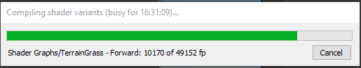
is there anything I can do to reduce the shader variants, like is all of them really needed?
16 hrs!!!! i'd just smash the screen if it would dare happen with me
not a pro in shader graph but have you simplified the shader , like stripping out unnecessary modules or something?
I suck at shaders so I didnt dare to edit the shader graph file :/ "TerrainGrass" is the only shader graphs shader, and thats the only one that takes forever
what's special in that shader comparing to unity's default one?
cant you better switch to default and cut that out?
it has winds proterties for the grass and it also has it built in " lod variant" system with works with terrain painting tool
it is form this asset
https://assetstore.unity.com/packages/3d/environments/unity-terrain-hdrp-demo-scene-213198

Elevate your workflow with the Unity Terrain - HDRP Demo Scene asset from Unity Technologies. Find this & other Environments options on the Unity Asset Store.
Have you confirmed they're transparent? Could be rendering the sprite frames (parts) through the texture and not through layering
could be doing some fancy stuff
do any body know how to get a noise similar to the noise outputted buy the gradient noise node in shadergraph?
im trying to make a basic buoyancy system but i need to replicate the logic i used in the shader into a script and i couldn't find any better way that to use a fixed noise texture (or textures) for bouth the shader and the logic in the script.
my current problem is that all the noise textures i tried are not as smooth as generating the noise in the shader.
I searched in google and said that I need a shader if I wanted to ever invert the colors in Unity, I want mine to invert all colors within my MainCamera, anyone know how?
question. how does ForwardAdd pass work? does it act upon already changed (in forwardbase) vertices (i am doing some things with geometry)? what about if i change vertex colors
Shadergraph is open source in the packages! You can reference it here.

GitHub
[Mirrored from UPM, not affiliated with Unity Technologies.] 📦 The Shader Graph package adds a visual Shader editing tool to Unity. You can use this tool to create Shaders in a visual way instead o...
Are you using the built in pipeline?
thank you!
For sure!
If you are the process is different from urp or hdrp. It's probably easiest in the most recent version of URP.
Because you don't have to write any code.

In this episode, we go over the very basics of Image Effects, and implement a screen displacement filter and a box blur.
Code and Resources:
http://danjohnmoran.com/Shaders/102/
Unity Image Effect Reference:
http://docs.unity3d.com/Manual/comp-ImageEffects.html
Kenney Assets:
http://kenney.nl
Intro Music by Tommy Moran
https://soundcloud.com...
I'm using plain empty 2D
Sweet! Check out that Makin stuff look good video.
There's a bit of setup involved but you're gonna take a shader and apply it to your cameras rendered image using blit - which renders an image into a render target.
The code when you get there for inverting is really easy
1.0 - the main textures color
the video talks about blurring the image?
Yep it goes a little further but should help you understand how post processing works
All you really need from it is in the first 3min
The boilerplate is that oncamrra render blit function
ah i see
hmm that would take too much time for me to setup just to invert the colors of my sprites, especially if my png would be inverted in the wrong way
What if I just wanted to invert certain sprites instead of the camera?
Oh I see!
You'd still want to use shaders
The catch is that you'd want a shader that inverts but is attached to your object
I see I see
The easiest way to write shaders right now is shadergraph imo
Bc it handles a lot of things like lighting / depth
But it's not always the most helpful for learning
You'd basically make a new material with a shader that can invert the sprite color
The problem you might run into is if you want to have lots of different shaders
And invert all of them
You'll have to put the same invert code in them
Ahh
but my game is really simple
All I need is a simple shader that inverts my small sprites
Plus the sprites get destroyed once they leave the camera view so, no problems in having too much shaders at once as well
Shaders are actually used to render pretty much everything in unity!!
The nice thing about the engine is you can look at unitys shaders too
hmm I see I see, but what would you recommend if I just really needed a basic inverter shader?
I'd give shadergraph a shot
is that part of unity?
You'll have to add it - it's an official package
Here's the line where it's called in the source!

GitHub
Unity Built in Shaders. Contribute to TwoTailsGames/Unity-Built-in-Shaders development by creating an account on GitHub.
GitHub
Unity Built in Shaders. Contribute to TwoTailsGames/Unity-Built-in-Shaders development by creating an account on GitHub.
just another question if you don't mind, this is the part responsible for the waves in my shader. but when i use the texture lod 2d it's not smooth but when i use the noise (it's not connected to the rest of the shader) it's normal and smooth.

Ah I see, but creating shaders for inversion is very easy yeah?
Very very easy! It's everything else that's gonna take you a sec to get used to
You basically take the color you want to output and then subtract it from 1
And that's it!
The everything else is keeping lighting support, catching sprite rendering, etc.
That's nuts lol! You could look at the code that shadergraph is generating
oooo thanks for the help!
Shadergraph should make all of that a lot easier though! For sure!!
the texture is fine actually i think it has something to do with the tiling and offset for example ?
Nothing super weird looking to me there. Hm.
Are you sure texture2d lod is the best fit for your function?
The lod part means it doesn't change mip maps
Which can make it look noisy at a distance
The other place to check w/the pixelation thing is in the filtering for the texture asset
If it's point you'll see the pixels
Where bilinear will make those transitions smooth
It could also be a resolution problem - the numeric approach to noise will always be more precise because it has infinite resolution. With the texture you can only approximate that.
Oh sorry I got off track
thank you so much
Oh cool!
I'd assume the tiling and offset node isn't changing the texture filtering but if you check the generated code you can know for sure.
no actually it's always important to like learn more
Sweet : )
I just wanted to make sure I wasn't missing your question
That's pretty much every way I'd tackle your problem
i just turned off the compression from the texture inspector menu
and that completely solved the problem!
sorry for wasting your time
No worries! I enjoy answering questions here. Thanks for letting me know how you solved it.
and also changed the resize algorithm to bilinear
testing some shader ideas using a shader graph, but I don't know how to prevent the offset being relative to the texture size, instead of absolute, as in the bigger the texture the more noticeable the offset is

the texture on the right is quite bigger than those on the left, and while using the same shader you can notice the shadow effect being relative rather than absolute so bigger texture means wider shadow
I can imagine that that is just how shaders work and there isn't much that can be done but I still ask just in case
if there is something that can be done so the offset is kept absolute and not relative
shader is currently, using urp, sprite (2d) unlit
this might be useful!
you can get the size of the texture you're working with in the shader
if you use 1/width you can get a normalized value from the width which will give you exactly one pixel
you could use the same variables to get the aspect ratio
which you could multiply by to get a constant offset if the issue is the proportions of the image
@deep moth thank you! did actually work ^^
sweet :- )
Guys, you know about triplanar node? How it makes the texture adapt to the gameObject UV and scale and stuff?
Can I do that but for a procedural texture instead of an image texture?
For some reason, I'm brain farting. I know there's some radial function or something I should be looking at, but I want to make a shader that causes my texture to fade from the center of itself over its life time.

I thought it'd be helpful to make a visual example at least.
Not out of the box but you can take similar ideas! Here's a nice implementation for triplanar mapping by Robert Yang
.... where?
You'll have to think through how to turn code into nodes
I can't help w/ that right now but I hope it puts you in the right direction!
But you didn't link anything, I am supposed to know how Robert Yang is?
Cause I don't XD
I suppose he ment this https://www.blog.radiator.debacle.us/2013/02/a-smoother-triplanar-shader-for-unity.html?m=1

But did you know if you hit f1 on a node in shadergraph it takes you to the docs for that node and you can see its “internal” code?
Oh omg sorry that's absolutely what I meant. Didn't link it on accident sorry!
So I see that SortingGroups only work with transparent materials.
I'm using 2D Sprites in a 3D world, so instead of being transparent, they are opaque and alpha clipped.
The characters are composed of multiple sprites though.
I can separate the pieces slightly in Z, but that causes the standard issue of overlapping characters sometimes having their arms/heads being sorted incorrectly.
Is there any way to get SortingGroup-like sorting with opaque object?
You'd need to disable depth
then you can change the rendering priority
few ways to do this such as doing it all via shader, or half-half using pipeline rendering objects
rather you don't want to write to depth, but you still want to depth test
I forget, it's been a while
Just use a lerp function on the texture's alpha channel, centered at the uv's of course (0.5, 0.5).
OK, it would be GL_Less (ZTest Less in HLSL?), this would probably give you similar results to Transparent Sorting, but then you'd have to question why use opaque and alpha clipping lol
Was thinking about this too, but assuming the the gold pile is opaque and the sprite is transparent, then there shouldn't be a problem here. The gold pile itself it tilted back a bit to allow partial clipping between pixels.
https://i.imgur.com/8CWQ2NV.png
Gold quad being opaque, with the white quad being transparent still respects depth sorting between the two.
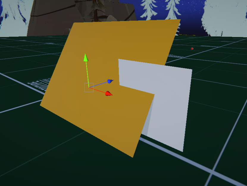
how to attach shaders into sprites 2d?
Boys
I've encountered something weird
This material does this on an iOS build

It's on a particle system, and it's the only one that does this
Put it on a normal sprite and it's fine, but on particles (non VFX graph) it does this
Shader is just a simple cutout one using clip() to cut out pixels below an alpha threshold
Those little smiling seeds are not supposed to look like that obviously
<@&502884371011731486>
Ty, is there a way to adjust it so I can leave an outer ring or something intact at the end?
Of course, you most likely want some way to clamp the distance of the effect. So, throw your lerp function inside of a saturate or clamp function or something similar where you can set the max radius from your uv center that you want the effect to reach out to. (presumably from the edge of your circle or whatever - some amount).
How can I store a 4byte data with an extra 1 byte index? I dont need a buffer of 8 bytes, but a packed 3byte and 1 byte falls short
Ty
If you're in raw HLSL, something like this is roughly what you want. Granted, I haven't actually run this. lol
// calculate distance from the center of our texture
float2 center = float2(0.5, 0.5);
float dist = distance(IN.yourMainTexUV, center);

// calculate transparency based on our distance from center
float transparency = saturate(1.0 - _Time.y - dist);

// apply transparency
fixed4 c = tex2D(_MainTex, IN.yourMainTexUV);
c.a *= transparency;

How did that error occur, and are there relevant yellow warnings or white info in the console additionally?
i have no idea how it started. everything was fine until i think when i dragged an fbx id recently edited into the scene
well now ive lost my error log window. how do i get it back
found it

none of the whites or yellows seem to be related
when i double press the other 2 pptr it brings me to visual studio
reopened project and this

Hey guys, Is it possible to use MaterialPropertyBlock for multiple instances of shaders to have different values, and also render them in one call? like batching all blocks or something
I just reaed about GPU instancing, is this the way?
the error message pops up when i click my avatar
It doesn't really seem related to shaders, more like something vaguely getting corrupted in the project or editor
I'd look into deleting project's Library, or even reinstalling the editor
I assume googling the "pptr cast failed when dereferencing" didn't produce any leads
no leads. ill delete projects
no idea what you meany by projects library honestly so i just reinstalled the editor but my project still has the same issue
all my other projects are fine though
could it have been the fbx i edited and reimported
I mean the folder named Library in your project
does anyone know how to make such shenanigen in shaders with sprites? kinda shrinking the sprite, there is not such thing as border, so basically border is where alpha turns from 0 to 1. I was thinking of scaling UV down, and add alpha 0 anything that is left, but I don't know how to do it, i'm very new to shaders


Doesn't look additive to me. The middle would be nearing white. If you want it all to be the same color, you need to prevent the sprites from drawing on top of each other. That's not really possible with transparency, but since your circles are one uniform color and transparency, you can use alpha clipped rendering instead.
With alpha clip, you can use depth or stencil to prevent the circles from drawing on top of each other.
how would that work for a render texture
mine just ends up looking like this


material is this
ah nvm found it in the shader
what should i set the threshold to
my render texture doesnt appear to take transparency properly either
the metaball camera is using a solid color for a background, and its white atm but the transparency is set to 0 so it shouldnt be visible

For metaball rendering, you usually want to render the balls as radial gradients, not as solid circles with a uniform color. And you want the circles to blend together, that combined with the cutoff afterwards is what gives you the metaball look.
i tried a lot of things, and what i got working was having some sprites with physics that get seen by a metaball camera, that can only see the metaballs
it applies a blur to them, and is then sent off to a render texture
that render texture is applied to a material which uses a color cutoff on the blue spectrum (since i cant get alpha to work because the render texture isnt accepting alpha values properly)
the material when centered at whatever x and y coordinate the camera has renders the metaballs in the same place they are physically, and the main camera only sees the rendering of the cutoff balls, not the physics ones
And the reason for why you want to avoid the additive blending is because it looks weird when it gets blurred and rendered as metaballs?
yeah
i want the center to be all one color, not changing based on how many metaballs are crammed together
my goal is just to make water, almost
not like realistic water but the stylistic choice
i kinda want to make it look like this

This is not an issue if you draw the circles as gradients instead of solid circles, which is usually how 2D metaballs are achieved. You won't need a blur then.
The merge looks a bit choppy there because they're using a texture that's not very high precision. You can do the gradient in the shader of the ball instead to get a precise gradient.
No, you can just output the inverse distance from the center of the UV.
sorry i cant really imagine what thatl ooks like in shadergraph im a bit slow
How are you rendering these circles, as SpriteRenderers?

Plug the UV position into a Distance node, comparing it to (0.5, 0.5). That gives you the distance from the center of the sprite, pixels closer to the center will be closer to 0. We want the opposite, white pixels towards the center, so we need to inverse it by plugging it into One Minus node.
The sprite you have selected in the SpriteRenderer matters here, because it affects what mesh and UV coordinates are used. As long as the sprite isn't in a sprite atlas and it takes up the size of a circle, or its mesh type is set to Full Rect in its import settings, it should work.
ok
whats a good introduction to shaders ?
i one day would like to be able to archieve something similar to this https://youtu.be/ERA7-I5nPAU?si=K5FbdrMZvSggrB8a

Date of Recording: 2020-11-14
I took a bit of a break from the usual tech updates this week to record a making-of video detailing what it's like to create a scene from start to finish in the Unity-based pixel art game engine I've been developing.
I found some neat modifier stack tricks in Blender for creating procedural, non-destructive detail...
so how do i get there? can u maybe even recommend some more advanced tutorials if theyre required for a similar kind of style
oh is this post processing?
oo this looks interesting
honestly nvm t3ssel8r now i think i just need some good basics on shaders/toon shaders any recommendations
Hello, I've got a problem. I'm starting to learn shaders and have been making some transparent shaders to practice. Then I tried combining two of these shaders but I can only see one at the same time. I searched for solutions but did not find anything that helps solve this. Does anyone know a solution?

I'm doing this in shadergraph btw, but could switch to code if necessary
yo that transparent thing is pretty cool
thank you!
Looks like some fun stencil buffer stuff. Nice.
Doesn't stencil only store one value?
yeah
How could I make it so the transparent materials get the colors from the other transparent material behind it instead of getting them from the opaque objects in scene
I semi-solved it by not making the objects transparent and instead making them opaque. But it only works fine with the blue distortion and the depth one. The blue scheme thing becomes black sometimes and does not show the cell shading effect

okay i did not fix anything it only works with the distortion because of fome weird interaction between a thing i added to the urp asset_renderer and the distortion shader
back to my old problem, the thing i did was not fixing anything, only getting things worse
Transparent objects often don't play nicely with each other; if you're sampling the opaque texture or similar then you won't be able to see any other transparent objects behind and would need to do some custom stuff to render everything that's supposed to be behind so your shader sees all of it.
how do people render transparent objects like glass or bottles in front of bodies of water without it breaking like my shader?
Usually those are simple and don't need to sample the background; it's just alpha blending. If they have to include refraction or reflections, they have to do something more complicated to render the background first and then the object on top
why does doing this turn the noise into a single value? i wanted to scroll the noise texture

The uv input of the noise is constant for all pixels, so the noise is constant also
You need use to add the result of the multiply node to the texture coordinates, and then input in the noise
where are the texture coordinates? sorry im still new to shaders
"UV" node
this one?

yes
how do you add if theres only an output?
"Add" node
like this?

yes
awesome
thanks bro
shader stuff is cool
seems very cimplicated though
i couldnt write shaders in code either 😅
If you are able to read through a shadergraph, doid the same in code is just the matter of transcribing it into the (often) same function and respect the execution order.
You can get by just by getting good with shadergraphs
dont feel like u need to be able to do it in code either
Yes, shadergraph should be enough in most of the cases, unless very specific things (like loops) that require code, and can be used through custom function nodes
Random question: Do shaders change a mesh's MeshRenderer? for instance, if i put a "Ocean Waves" shader on a plane, would the mesh renderer become wavy? (I'm doing it in my project and it looks like not. But if not, what exactly is a shader changing if not the mesh renderer?)
They don't change it, shaders can deform the mesh by moving vertices
Oh but the vertices only move on the GPU right? with shaders
Yes
okay now that's making sense! Thanks
Hello
how do i make it so instead of the color being black its transparent?

You're looking for "additive blending", or you'll want your texture to be fully white with the black&white color used as the alpha channel
im using gradient noise

cant i like minus black or something
You can use the b&w color as your alpha with the base color / whatever your visible color property is as fully white
I think premultiplied blending would also work here, but I agree, the noise should only be used as the alpha, not the color output.
im multiplying it by my interasection shader that i made, is that not how u do it?

Don't use the noise as base color, use fully white instead
this seems to have worked

is there a way to do like scrollspeed.x?

It's a bit weird to go from a Vector4 to a Float for alpha. It will only use the first (x / red) component here. Perhaps you just want the split A output multiplied by the noise.
i figured it out, i wanted to make one go left and one go up to make it a bit more interesting

Split node is used to access the components of a vector. .x would be the R output.
Or can use a Swizzle node and type in X or R in the field
i ended up just making scrollspeed a float

shader graph is really cool
my first time messing without a tutorial

The time output is already in seconds, shouldn't need to do anything to it
how would I make this effect
