#archived-shaders
1 messages · Page 61 of 1
Then you didn't complete the process
If your project is well along, changing render pipelines can be a big change so research it first
Hello, I am trying to make a shader that I can apply to objects dropped on the ground (just to give their edges a little glow). The thing is, the items already have a shader applied and updating it to my glow shader will change the look of the item. I just want to add glow and nothing else. How would I go about this?
Hey there, I was wondering how I could make a shader graph material that would dissolve all the other materials on an object. Basically, I want the white part of the object to be transparent.

Anyone know if there is a node in the full screen shader graph that basically uses the current screen as a texture?? Like render textures would but more of a shortcut?
how do i make a default urp material capable of tiling on a per gameobject basis
rather than tiling every object with the same material
https://docs.unity3d.com/ScriptReference/MaterialPropertyBlock.html you can use this from a script

thanks
do you know how to use it though ?
this is what i tried
var mats = GetComponent<MeshRenderer>().materials;
foreach (var mat in mats)
{
    var mpb = new MaterialPropertyBlock();
    //adjust uvs to match scale change
    mpb.SetVector("_MainTex_ST", new Vector4(1, (float)scale, 1, 1));
}
go.transform.localScale = new Vector3(1, (float)scale, 1);```

its not clear to me how it links to the materialsYou set your prop block in the renderer https://docs.unity3d.com/ScriptReference/Renderer.SetPropertyBlock.html
will that work in edit mode aswell
I dont see why not
i tried this:
var renderer = go.GetComponent<MeshRenderer>();
var mats = renderer.sharedMaterials;
foreach (var mat in mats)
{
    var mpb = new MaterialPropertyBlock();
    mpb.SetVector("_MainTex_ST", new Vector4(1, (float)scale, 1, 1));
    renderer.SetPropertyBlock(mpb);
}
but the values in the inspector didnt change
Hmm for multiple materials I believe you should provide a mat index to the set method as well. It is also good advice to first get the property blocks from the renderer modify them and set them back
The URP Sample Buffer node can give you access to the Blit Source
Thanks I'll check it out 👍
@quaint grotto should avoid using MaterialPropertyBlocks in URP as they break the SRP Batcher compatibility. Better to instead use GetRenderer().material which'll create a material instance.
_MainTex_ST likely won't work the default URP material, the reference would be _BaseMap_ST instead. It would be set to Vector4(tilingX, tilingY, offsetX, offsetY);.
But there's also .mainTextureOffset/.mainTextureScale that should work. Or .SetTextureOffset()/.SetTextureScale()
Creating a different material for every object probably isn't ideal. Probably better to keep references to the materials and reuse them if the tiling matches. Or just manually create & assign the materials.
Sorry, I'm new to shader graph. Why isn't my texture showing up on my object?

I am using URP btw
If you mean the result isn't what you expect in scene, these are things to check :
- Is graph saved? (Save Asset in top left)
- Is texture assigned to the material, and DetailStrength set to something larger than 0
- As the texture sample uses UV0 input, is the mesh you're applying the shader to UV unwrapped
You can also assign default values to the properties in shader graph (click property, set default field under Node Settings tab of Graph Inspector window), that will show better previews in the graph, if that's what you mean.
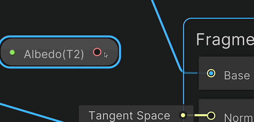
Its just the following image, It shouldn't need to be uv unwrapped i dont think:

Meshes need to be unwrapped if you use the default UV0. That accesses the first UV channel in the mesh, it's what tells the shader how to apply the texture to the model.
(There are alternatives, like Triplanar mapping but that's more expensive. You'd likely just want to unwrap your model here.)
Also, this is a normal map so you'd typically use Normal mode on the Sample Texture 2D and connect to the Normal (Tangent Space) port, not Base Color.
How do I unwrap the texture? Sorry if that's a dumb question
You unwrap the model (in software like Blender), not the texture. If you google "UV unwrapping tutorial" you should get some info.
The mesh is procedurally generated so that's not really possible
Then you'd need to generate UV coords with the geometry. Or if it's quite flat, like a terrain, you could instead project the texture from above using the vertex positions, like this : https://www.cyanilux.com/faq/#sg-planar-mapping
How would I generate the UV coords? This is my code to generate the terrain:
does anyone know how to fix this shadow in cutout texture ?
I've looked on different sites, but I haven't found anything.

Does the shader have a billboard behavior, where it always faces the camera?
Welcome to the next few weeks of trying to minimize self-shadowing on your quads
idk
it's the standard cutout shader, maybe not
What is the box collider at the bottom? And why does it appear to be aligned with the shadow?
What's the name of the shader, specifically?
because I'm using this for tabletop simulator, it's like having the sprite standing
like this

Standard
Ok, but then why isn't it aligned with the sprite in that screenshot? Isn't that strange?
Are you able to look at the sprite side on, or does it rotate to always face the camera?
it rotate to always face the camera
Okay. I know the Standard shader doesn't have that behavior, so that's happening by some other means. Do you have a script on the object that might be doing that?
no, it's just the particle system to make this, and the box collider
The shadow shouldnt render like that with a basic lookat script, so it's being alligned in the shader, no?
Alright, that's a pretty non-standard set-up so that would have been good to mention.
I don't have much experience with shadow casting particles, but this sort of problem can be explained by the particle system orienting itself to face the shadow mapping camera, which will make it appear to be facing the source of light when you look at its shadow
idk
it's just with the cutout rendering mode this happened, like
with something else, the shadow doesn't work correctly (screenshot 1) but with cutot the shadow works but this happened (screenshot 2)


Oh, so you're talking about the shadow that it's receiving, as opposed to the shadow it's casting on the ground?
I actually find that pretty bizarre to use the particle system for this, but hey if it works
no no
the shadow it's receiving for the house AND for the token
on the image itself
Because the shadow it's casting is obviously wrong here. The shadow is flipped, with the hanging straps on the wrong side, and the feet are not aligned.


But both issues are symptoms of the same problem. The billboard behavior is rotating the sprite separately for the main camera and the shadow camera.
This seems to be an issue with Particle System, but it's hard to call it a bug because you're using it in a very unconventional way.
Since this is for Tabletop Simulator, I'm assuming you can't create your own scripts to put on this object? And that's why you're resorting to hacks like using Particle System to draw one persistent particle with billboarding?
Funny thing is, from the perspective it does look like the shadows should be aligned like that, it's just that they need to be panned out a bit more
yes
because they are just too inward to the sprite that it's self shadowing
Well if you want to continue using Particle System for this, then this is not fixable.
Alternatively, you can create a shader that does vertex displacement to rotate the mesh to always face the camera.
This isn't just a particle system problem though, it's hard to get the shadowing to the base of a quad without it shadowing itself, and usually you'll have to use a bunch of tricks to get it working in URP.
You can just disable intake shadows completely if you want

Im pretty new to unity, I have a toon shader and a toon material setup I have managed to get the toon lighting to work on objects but I cant figure out how to make the light affect terrain grass It seems to just diffuse it, could someone possibly help or mention an alternate way of doing things https://youtu.be/2SaLs6dE12w

Just a quick test of my grass system
Hey there, I was wondering if there is a way to make a dissolve shader that affects all materials on an object, without changing the values of those materials.
Basically I don't want to manually make a duplicate material for each of the original ones, I just want to use one shader graph and one material to do the dissolve effect.
Hello! I am developing a VR app for Quest 2 using unity that involves loading OBJ files during runtime. The asset I found to do the importing requires the "Standard (specular setup)" shader to be enabled in order for the files to show up. But when I have this specific shader enabled the build time goes from 1-3 minutes all the way up to 20-30 minutes. I included a screenshot of the longest part of the build process. Has anyone encountered this before and is there any way to use this shader without such long build times?

I've been trying to do this for a while now, but I can't figure it out. Can someone help?
I want to recreate the Night Vision effect
Hi, I’m trying to get a shader to hide all objects above the player for multi-story cutaway buildings (including furniture, monsters, other players, etc) anyone know how I can do this? Do I have to make everything in the whole game use the same shader? Can I use some sort of clipping plane?
When i use GetRenderer() it warns me about leaks in editor mode
Instantiating material due to calling renderer.material during edit mode. This will leak materials into the scene. You most likely want to use renderer.sharedMateria
this is the issue
Camera Depth Texture Bug for a heat distortion trail
Hello everyone - i am trying to make a heat distortion trail for a sword swing so it looks like the air is bending in it.
But it create a lot of _CameraDepthAttachment_1069x667_Depth_MSAA4x and also _CameraNormalsTexture_1069x667_R8G8B8A8_SNorm_Tex2D_MSAA4x. Does anyone know why that happens and why it increase my memory usage so much. Here are some images for it and from the shader:


Hello. I Made vertex-paint shader to my scene, and it workes. But after baking the light and adding light probes i have weird black spots where its painted. https://cdn.discordapp.com/attachments/917756226820010004/1159406535592652880/image.png?ex=6530e87a&is=651e737a&hm=91e3ab55d4ab175735dcba6cebea49590568f9b35c51d99627ec55e3936b3e8e& https://cdn.discordapp.com/attachments/917756226820010004/1159406871497674782/image.png?ex=6530e8ca&is=651e73ca&hm=b96a8d59f5a72cc7c14e06b3da75c2f90c687ab236fa27e096794780b7b18671& What can Cause this problem?


is there a way to use shaders to hide objects above a certain Y value? Without making all entities use the same shader?
How do I refactor this so that I can fill each cell in a specific order?

the order being either rows or columns, but preferable the order being any order I want
essentially just a direction as the order, where 0,1 or 1,0 does rows or columns sequentially, and other values do the inbetween

its getting close but its still not right
I cant control what direction the gradient fills in from
no matter what variables I use, I cannot get the exact specific look I am trying to get and its immensely frustrating which is only making it harder
and I need help to solve this, I havent been able to do it on my own
What's the mathematical formula that takes in a grid of XY dimensions, and a vector2 direction, and returns a sequence that visits each grid space sequentially, where visit is defined as containing a value exactly 1 greater than the previous cell?

I want every single cell to fill in exactly after the previous finishes, which means each cell must have a value of +1 relative to the previous cell
I know for sure a formula exists that solves it
where no matter what the dimensions are the direction returns cells that are all +1 from previous cell
its so easy to verbally describe the relationship but impossible to write trigonometry same
I hate math so goddamn much
I'll admit, I have no idea what you're trying to explain.
Okay ill try to break it down into its individual components:
Grid of X/Y size.
Every cell is a gradient value between 0 and 1 in a direction
Every cell adds an integer to the entire cell
the 'sequence' is sent to a Step function, step now fills each cell sequentially
things that must be variable:
the direction of the sequence
the direction of the gradient within the cell
the xy dimensions of the cells
since words are hard

here is a gif that is almost working but not working at all the way I want
this is at like 80% of the way to done except the problem is beyond my knowledge and ability to solve, but it MUST be solved and i must be the one to solve it but I cant solve it so I have to ask for help to solve it
there's no other path forward
Every cell adds an integer to the entire cell
This I don't get.
Lets call this an XY problem
What I WANT is to fill each cell individually fully completely before moving onto the next cell
what I think will do that is to add +1 to every sequential cell
pictured: cells not completely filled before the next cell is already beginning to become filled

what I actually want is to add +<any variable> to control the rate of cell fillage eg. I could make it do one cell at a time, or all cells, or some other thing
but I canteven get one cell at a time going
big ol not working

So can I think of this as you have some cellsThatShouldBeFilled number that you're increasing, and as it goes up, cells should fill in some sequence, I guess left-to-right and from top-to-bottom, but cellsThatShouldBeFilled is a decimal number, so if it's set to 3.5, then the first three cells should be completely full, and the fourth half full?
drew this before reading what you just posted, let me explain and then read yours

if the grid was 3 x 3 for example, I want to add the listed value into the cell as shown, and that value would be determined by a direction vector, shown in green
but I want it to work on any grid size or direction value
you can think of it like wrapping around a line continuously

unless Im just completely dumb and this is not possible to achieve
reading this now
Sorta? I think my diagrams hopefully answered the intent there
Hmm, so the number of columns doesn't really matter. For example, if you ignore the numbers and see the columns I added, the green line is still the same.

So it's just a bunch of rows that have a height and width.
another example, if the direction vector was exactly 45 degrees, this would be the expected cell fill sequence

pretend my diagram was square
but its supposed to work no matter what XY dimensinons and no matter what direction
Okay, but if you had this working properly, would I be able to visually count how many columns there are, like I can in your non-working WIP?
which currently I can't get the cells to fill sequentially outside of very specific confluxes of magic numbers that don't meet my use case
I am not sure what you mean by that, yes I guess? There should be rows and columns
Are the cells intentionally labeled 1, 2, 3, 2, 3, 4, 3, 4, 5?
thats the sequence values as in the order I expect them to be filled
they wouldnt have numbers in them
So the two cells that you labeled "2" would fill at the same time?
in the second example yes
Now you've lost me.
I want to fill cells
by row and column
sequentialyl
no subsequent cell fills before the previous finishes, or rather the sequence is a variable
so I can say, start the next cell at 0.5 of the previous, where 1 would be wait completely
and 0 would be all cells fill at the exact same time
hm writing it like that, my sequence value would be multiplied by whatever input value then added 

still not really working
Anyone know how to get object scale in Shaderlab? I wanna do this same effect but in Shaderlab
https://twitter.com/AndreaG_3D/status/1613582447857254401?ref_src=twsrc^tfw|twcamp^tweetembed|twterm^1613582447857254401|twgr^6d8366f23809a1ef3a262d92c9c6cd76bf4b6b1c|twcon^s1_&ref_url=https%3A%2F%2F80.lv%2Farticles%2Fbreakdown-auto-scaling-uvs-in-unreal-engine-based-on-object-scale%2F
All is contained in this simple material graph 👇
But there are some things to consider when implementing it, this setup supports tiling based on scale only on 2 axes, which means that all models that'll use it'll need to be oriented along the required axes to avoid artifacts
2/7


here is getting almost there, a little closerm 90%
but as you can see its still acting like a 'wave' and not filling cells sequentially

I had to throw in a ton of ugly hacks, random multiplies, remaps everywhere to get it to do this
this is the behaviour I want and was trying to describe
but that above ONLY works for that exact pile of ugly hacks magic number
I want it to work for any grid size without relying on shitloads of magic numbers
I posted here a few times, wondering if someone can help me. Trying to make a clipping shader for all objects above the player.
Okay, but where does the direction come in? Is this a hard-coded example where the direction is up (or left/right)?
in that example its hard coded yeah

https://www.shadertoy.com/view/msGyDG I believe this should have the functionality you want :)

Do you think the if else will matter if the shader is for mobile? Or am I old fashioned and if statements in shaders are really noticably unperformant for something this basic?
Otherwise yeah that looks 100% exactly spot on; the sine was just for debugging the values though lol
The if/else is just to draw the square in the grey background
Does that mean its not neccessary in some way?
Ooh right like its so that the shader doesnt fill the entire shader toy window?
Yeah exactly
Gotcha, now I understand 👌
Yeah this looks great, thanks a bunch. I knew it could be solved since there were bery clear mathematical relationships but I knew not how to find them 🤔
Tbh I just messed around until it worked, no rigorous calculations really
thats fair. Did you change it just now? I reopened it and the behaviour is different
I assume some variables changed was the reason why
it looks like some cells are actibating out of sequence
Oh I was messing around and might've saved after changing DIREC
If it's (GRIDNUMBER, 1) then it'll fill in order
hey, I'm working on a horror game, and I'm very new to shaders
i managed to get this edge detection effect working, in which a sphere gameobject slowly expands and whatever intersects its surface is highlighted
is there any possible way i could get the edges of geometry inside the sphere to also be highlighted, such as the corners of these walls?

(shitty mspaint example)

looking more into this,
https://halisavakis.com/my-take-on-shaders-spherical-mask-dissolve/
i could potentially use something like this? simply have the walls already have glowing edges and clip pixels outside the radius of the sphere
how can I create a similar effect to sprite renderer tiling, while using Shader-graph and "ellipse" node?
That is:
- I have a shader-graph that generates a circle using Ellipse node.
- I have a wide rectangle which uses that shader graph. The UVs are from (0, 0) to (width, 0). For example, width would be something like 11.
- The end result is a single ellipsis, but I want to do much like tiling a texture - and end up with multiple ellipses.
Hey I am having issues trying to get my toon shading lighting to apply to my terrain grass anyone got any tips or recommendations, do I perhaps have to code toon shading into my already exiting material for grass? I have already got a toon shader that work for objects as you can see on the box https://youtu.be/2SaLs6dE12w
Just a quick test of my grass system
back now porting this to unity - your grid size is a float here if I understand correctly? Will ti be hard to make it non uniform?
xy and and not just a value?
porting this over im just sorta guessing at what all thes equvuilate to

void ShaderGridFiller_float(float2 uv, float SQUARESIZE, float GRIDNUMBER, float FILLLEVEL, float2 DIREC, out float indexer)
{
    float majorFill = floor(uv.x * GRIDNUMBER) / DIREC.x + floor(uv.y * GRIDNUMBER) / DIREC.y;
    float minorFill = frac(uv.y * GRIDNUMBER);
    float maxFill   = abs(dot((GRIDNUMBER - 1.) / DIREC, float2(1,1)));
    float majorBias = max(DIREC.x, DIREC.y);
    float totalFill = (majorFill + minorFill * majorBias) / maxFill;
    float fillCheck = (majorFill + minorFill / majorBias) / (maxFill + 1. / majorBias);

    indexer = step(0., fillCheck - FILLLEVEL);
}```
testing this nowalso I just noticed no value of that is the 'time' yours was using, how do I actually -use- this?
I will try to figure out how its meant to be used and where I pass in 'time'
oh FillLevel must be that

it just returns black no matter what parameters I pass in

fillcheck returns broken pink, I assume its a division by 0 happening?
#define SQUARESIZE iResolution.y/2.0.9
#define FILLLEVEL (0.5sin(iTime/2.)+0.5)
#define GRIDNUMBER 5.
#define DIREC vec2(5,1)
is the problem that your pass in values arent just static values, they're sub methods?
oh progress 👀

hm little confused how direction is meant to be used
making a gif

oh is direction supposed to be the direction of the gradients?
or something else? I feel like this thing is missing a lot of the 'directions' its supposed to have
like 0, 1 is a direction but it returns black and I dont know why
void ShaderGridFiller_float(float2 uv, float2 direction, float2 resolution, float time, out float indexer)
{
    float SQUARESIZE = resolution.y / 2. * 0.9;
    float FILLLEVEL = 0.5 * sin(time / 2.) + 0.5;
    float GRIDNUMBER = 5.0;

    float majorFill = floor(uv.x * GRIDNUMBER) / direction.x + floor(uv.y * GRIDNUMBER) / direction.y;
    float minorFill = frac(uv.y * GRIDNUMBER);
    float maxFill = abs(dot((GRIDNUMBER - 1.) / direction, float2(1,1)));
    float majorBias = max(direction.x, direction.y);
    float fillCheck = (majorFill + minorFill / majorBias) / (maxFill + 1. / majorBias);

    indexer = step(0., fillCheck - FILLLEVEL);
}
my current broken version
FILLLEVEL should be an input to the function (though time works actually)
I assume ive fucked it all up in my attempt to port it from GLSL to HLSL
oh yheah saquare size isnt even being used because it was multiplying the UV before
Don't use the resolution thing; the actual part that makes and fills the grid just uses a (0-1) UV
now Im confused and lost, I was just about to use the resolution thing
now I dont know what I should do to progress forward in making this do what I intended
This is the relevant part; it calculates the UVs for the square at the top and they just range from (0-1) in x and (0-1) in y

I'm assuming you're applying this to a quad or something and it doesn't matter what happens outside that UV range
Yeah its a quad 0 to 1 value range correct assumption
I think this should be right actually since you just take in the UV and use it as is

I think im just making it worse
it keeps ping-ponging but that behaviour was just because I was using sine to show the value scrub
okay I see the sine inside Ill.. not remove that
because its already broken and im breaking it worse with each attempt to fix the last thing I broke 😬
Both components of direction should be >0 and FILLLEVEL should be an integer if you want the grid to line up with the UVs (I think HLSL casts nicely where GLSL doesn't? But no harm leaving it as float)
I think if both components of direc are integers, then the filling lines up with the cells (otherwise cells along the diagonal fill line will be filled different amounts)
Having FILLEVEL an input would be best I think, just so it's easier to change in future
debugging variables to see what they're doing outside of the black box, progress

cells and gradients I see them now 👀
I am a little confused as to why 'Direction' changes the size of the cells
direction and cell size should be unrelated?

im also confused why direction blows up if either axis is a 0.
I know the answer is because the divide by zero
but that shouts red alerts to me
that direction is not a direction
because directions can have zero values
It doesn't change the size but it changes the major fill since the major fill decides which cells fill first, and that depends on the direction
I am trying to parameterize every single assumed value
assuming that I dont want to assume anything, how do I unassume them
or rather, what do I want to not assume?
The assumption of value ranges 0 to 1 is not an assumption I want to change 🤔
I am slowly trying to expose what is assumed to passed in variables so far
The direction is basically 'how many cells should i fill along x before i start filling on y'; filling zero cells on x before you start filling the next cell on y means the second cell on x has to wait for infinitely many cells to be filled. Something like that
Ohh
okay so the direction was not a direction, it was 'fill this many cells before next'
which explains why a 'direction' of 1 , 1 filled in 45 degrees
The direction and grid number are the main free parameters; you can also play with how major and minor fills are calculated as long as they end up in the same range

okay I see now, its essentially flood filling out
with this particular conjunction of values
Okay my comprehension is growing, I feel able to evolve it further now
Thank you for the continued support 🫂
you're welcome :)
If I make grid number not a float but a float2, what then does become this value?

is this how I should be changing grid number?
its obvious to apply x to y and y to y
but that instance of its use isnt to a specific channel
I would guess replace GRIDNUMBER there with dimensions, and the float2(1,1) with normalize(dimensions) perhaps?
hmm no it doesn't fill all the way in the shadertoy...
oh looks like it should stay (1,1), and replace GRIDNUMBER there with its float2 counterpart
(because the (1,1) is from the max value of the UVs, not anything related to the grid)
void ShaderGridFiller_float(float2 uv, float2 dimensions, float2 direction, float time, out float2 indexer2, out float4 debug)
{
    float cellFill = floor(uv.x * dimensions.x) / direction.x + floor(uv.y * dimensions.y) / direction.y;
    float gradientFill = frac(uv.y * dimensions.y);

    float maxFill = abs(dot((dimensions - 1.) / direction, float2(1,1)));
    float majorBias = max(direction.x, direction.y);
    float fillCheck = (cellFill + gradientFill / majorBias) / (maxFill + 1. / majorBias);

    float indexer = step(0., fillCheck - time);

    indexer2 = float2(indexer, fillCheck);
    // Set debug output
    debug = float4(cellFill, gradientFill, maxFill, fillCheck);
}
I am renaming the variables to make them clearer to myself
major and minor fill were the cell value and the gradient within the cell
but I am not sure what maxFill, majorBias, and fillCheck do with that new understanding 🤔
like what does it mean to max fill something, that's just a value of 1 right?
maxFill is just so that instead of going from empty to full over a range from 0 to some random number, it normalises it so it fills over the (0-1) range
oh remaps to a normalized range, gotcha
And majorBias converts between the units for cellFill and gradientFill, so it knows how much gradientFill equals one cellFill
hmm and this is FillCheck

cell+gradient divided by how much gradient per cell
divided by the remapped 0 to 1 range
oh and then we step it
its the threshold
yep
for some reason I was missing the indexer = step
hopefully it works now?
Yeah im almost done, its at that 99% point where I am trying to remember what I was even intending to do with it before getting neck deep in the trenches
I think I want to change the direction of the gradient per cell

is the extra thing I was about to do
so I have to check what I was doing before
void GridWithGradient_float(float2 uv, float2 gridDimensions, float2 gradientDirection, out float outer)
{
    float2 cellUV = frac(uv * gridDimensions);

    float2 cellCenteredUV = cellUV - float2(0.5, 0.5);
    float gradientValue = dot(cellCenteredUV, gradientDirection);
    outer = (gradientValue + 1.0); //* 0.5;
}```this was my old bad code
but it was full of flaws like I coudnt forcefilly just say 'make it a range of 0 to 1
it constantyl returned values out of range
just make sure it still ranges from (0-1); if you make a direction vector, you can calculate the gradientFill with dot(fract(uv*dimensions), direction)/max(direction.x, direction.y) I think
Yeah that was my problem right there bingo
I couldnt make it still range from 0 to 1
as soon as the gradient isnt moving purely in one direction
because when you rotate it even a little bit now there's values beyond if the range WAS 0 to 1 across a square
right other things I wanted to do was adjust how fast the cells fill even, which in my mind would be achieved by adding more cell per cell
like your version is carefully constructed to stop lerping one cell and begin lerping the next cell at -exactly- the end moment
but what if i want a little before a little after, some play to make it feel and look right
I think you could do that by messing with majorBias
It would still start filling at t=0 so if you want the same delay at the start and end you would have to do something a bit more complicated
*max(abs(direction.x), abs(direction.y))
Will try those now
Ive also been working on this since 8am so my brain is tried, its 5pm here
literally none of what I did before you linked my your shadertoy version ammounted to anything 😬
Anyways we got the results now
I was skilfull in reaching out for help, even if I didnt find the answer by my own hands 😣
immensely frustrated and pretending im not because this always happens even though I know no one can know everything and do it all 🔥
but thats mental health, not trigonometry
Anyone here having luck reading a rw buffer from a vertex shader filled via the shader's vertex id?
which shader does support Reflection Probe except unity's Standard Shader!!!??
Hi i got question is there any good guide that could help me recreate swirl effect from world of warcraft

i dont know if this is the right channel to ask this but i want to know if anyone know why my build is all pink like this
it's normal when run in the editor but pink in the build version

shadergraph has a spiral node
Is it a common optimisation tecnique to start the vertex shader with indices, and then read out the vertex data from a uniform buffer?
This seems very good for rendering huge ammounts of simmilar meshes, since compared to batching you can decide what mesh you want to be drawn
I'm having some issues with the "Power" node.. or rather the pow function in HLSL.. Its probably me not properly understanding stuff. But if I do something like this
float3 a = <world space normal>;
float b = 2.0;
float3 c = pow(a, float3(b,b,b));
The result in C seem to be absolute values as soon a b is assigned a non integer value.
To clarify, I'm doing this in ShaderGraph

the code in "MyPower" is:
Out = pow(A, float3(B,B,B));
Same thing happens with the regular power node
output with integer values on B

Output with non-integer values (in this case 4.2)

IIRC, this is expected, as non integer power of negative values is undefined.
To fix this, power the absolute, and multiply by the sign
THANK YOU! I was not aware of that.
did I make a mistake in recreating these nodes in code? its not returning the same result and im not sure why


    float gradientFill2 = frac(uv * dimensions) - halfCell;
    gradientFill2 = dot(gradientFill2, gradientDir) + halfCell;
left is the expected return, right is what I am gettting instead

These lines should be a float2 variable
I'm a little confused, which part of them should be a float2? the gradientfill debug value?


Im trying to debug right now why its failing to look like that frac right from the first function
making this a float2 just breaks everything


oh its this line being float2'd?
There's a bit of a mix because uv is float2, but dot() returns a float
I think I understand now - I wanted a float eventually but i converted to a float too early (at the UV step instead of the dot step)

The dot needs to take two float2 inputs, after it can be a single float
Yeah, I'd probably change it to
float2 gradientUV = frac(uv * dimensions) - float2(0.5, 0.5);
float gradientFill = dot(gradientUV, gradientDir) + 0.5;
I was thinking the same thing, I used an unclear variable name that ended up confusing me
will do that now 👍
pebkac
Multiple Pass, Stencil, Surface Shader Conversion from built-in-render pipeline to URP
I have a shader in Unity which is compatible with the built-in render pipeline. Which I want to convert into URP
Here is the basic structure
Shader "test/ClothStencilTwoPassDefault"
{
    Properties
    {
        //some properties
    }

    SubShader
        {
            Name "Pass 2"
            Tags {"Queue"="Geometry-1" }

            Cull Front
             Stencil
        {
            Ref 0
            Comp GEqual
            Pass Zero
        }

        CGPROGRAM
            //Some variable declearation

            void surf (Input IN, inout SurfaceOutputStandard o)
            {
                   //surface shader function magic
            }
            ENDCG

            Name "Pass 1"
            Tags {"Queue"="Geometry-1" }
            Cull Back

            Stencil
        {
            Ref 1
            Comp always
            Pass replace
        }

            CGPROGRAM

        //Some variable declearation

            void surf (Input IN, inout SurfaceOutputStandard o)
            {
                    //surface shader function magic
            }
            ENDCG
        }
    FallBack "Diffuse"
}
I have tried using a BETTER SHADER https://assetstore.unity.com/packages/tools/visual-scripting/better-shaders-standard-urp-hdrp-187838
Here is the documentation of the same https://docs.google.com/document/d/1UUSIOIiq4dK8OMDyGHqpsURxsYBYmwKaPo0zOZ5vkHk/edit
I am not able to find the syntax to implement multipass with stencils in a better shader.
The goal is to get the shaders to work in URP.
Hey guys. I have a question - what is the most efficient way to blend more than 2 normal maps in Unity with Mask? For example - I can lerp 2 normal maps and it works fine, but when im trying to add one more lerp with one more normal map its giving me a bad result. Normal Blend its not good solution because it doesnt have input for mask

Why don't you also use lerp on the right ?
idk if it falls here, but the characters in my scene kind of blend in with the background and stuffs
how can I make the characters stand out?

If you can define how you'd like them to stand out, if would help to answer.
BTW, your groud looks very shiny, that's not really normal 😄
so something like a bit shiny or something
or maybe a little brighter?
ya, the ground is like really reflective as well. No idea about how i got that
Then you could :
- Use a dedicated shader for your character that would add a sort of rim light to them
- Use an additional light that would lit only characters, using the light culling
oh thanks for the tips
Will try them out, thank you
@regal stag hey that blur shader you gave me is a great addition, however I can't seem to get it working in conjunction with the normalmap distortion noise and not get visual artifacting in the shader... Could you help me out, please? notice how in game view (second panel), the shader only stacks the particle effect vertically but not horizontally.


Anyone, or I am on the wrong channel?
You are.
So, first of all, URP won't handle multi-pass shaders.
You have to tell the renderer to re-render the objects you want using rendererfeatures or ScriptableRenderPass
Second : While you can write shader in URP with shaderlab, URP doesn't support the surface shader declaration that handles all the boilerplate for declaring required passes in the built-in renderer.
The easiest is to re-do the shader with shadergraph.
Might need to adjust shader/pass Queue tags? I don't really remember the details of this that well - it may be better to phrase it as a new question (to everyone here), and share the shader code.
When im trying to lerp 3th normal map its not working properly
So I've been editing Kelvin van Hoorn's blackhole shader to work in vr and I'm getting there, but now the gravitational lensing makes sense in the left eye, but in the right eye the whole sample scene color looks to move when I move my head around.
Using single-pass and urp, anybody got an idea how to fix?
(It's a raymarching shader btw if that matters)
If I want to draw a mesh with a vertical gradient that starts at the bottom-most vertex and ends at the top-most vertex, do I have a way to do it without manually inputting vertex positions?
Also a normal map would be good to break up the lighting on the ground
is there anyway to make transparent decal not overlaping with each other.it looks like this, but for decal

For shadows, right? I think I ran into this problem before but instead used some mask and did some replacement methods using render objects.
No clue if it was optimal, but it worked.

if you or anyone cares to help me out on this, I'm willing to pay so that it gets done properly
can you tell me how to do the setup for this?
Don't really have Unity open right now, but it's basically just some stencil stuff. You could probably just do it all in a shader, but if you've not used stencils before, you can get an idea by messing around with render objects since their settings compile just as quickly.
i see, thank you 
Maybe look up stencil blob shadows. I do believe people develop them this way.
sure, will do
I'm currently trying to make a realistic jet exhaust heat particle effect by combining these two into one, but when I try it, It doesn't work. the former shader produces distortion, and the latter produces blurry squares. how do I make it so the shader only shows blur on the opacity mask texture of the former shader combined with the refraction of the normalmap?


this is the custom blur shader: `// Upgrade NOTE: replaced 'mul(UNITY_MATRIX_MVP,)' with 'UnityObjectToClipPos()'
Shader "Custom/Heat Blur"
{
Properties
{
_Factor ("Factor", Range(0, 5)) = 1.0
}
SubShader
{
Tags { "Queue"="Transparent" "IgnoreProjector"="True" "RenderType"="Transparent" }
    GrabPass { }

    Pass
    {
        CGPROGRAM
        #pragma vertex vert
        #pragma fragment frag
        #pragma fragmentoption ARB_precision_hint_fastest

        #include "UnityCG.cginc"

        struct appdata
        {
            float4 vertex : POSITION;
            float2 uv : TEXCOORD0;
        };

        struct v2f
        {
            float4 pos : SV_POSITION;
            float4 uv : TEXCOORD0;
        };

        v2f vert (appdata v)
        {
            v2f o;
            o.pos = UnityObjectToClipPos(v.vertex);
            o.uv = ComputeGrabScreenPos(o.pos);
            return o;
        }

        sampler2D _GrabTexture;
        float4 _GrabTexture_TexelSize;
        float _Factor;

        half4 frag (v2f i) : SV_Target
        {

            half4 pixelCol = half4(0, 0, 0, 0);

            #define ADDPIXEL(weight,kernelX) tex2Dproj(_GrabTexture, UNITY_PROJ_COORD(float4(i.uv.x + _GrabTexture_TexelSize.x * kernelX * _Factor, i.uv.y, i.uv.z, i.uv.w))) * weight

            pixelCol += ADDPIXEL(0.05, 4.0);
            pixelCol += ADDPIXEL(0.09, 3.0);
            pixelCol += ADDPIXEL(0.12, 2.0);
            pixelCol += ADDPIXEL(0.15, 1.0);
            pixelCol += ADDPIXEL(0.18, 0.0);
            pixelCol += ADDPIXEL(0.15, -1.0);
            pixelCol += ADDPIXEL(0.12, -2.0);
            pixelCol += ADDPIXEL(0.09, -3.0);
            pixelCol += ADDPIXEL(0.05, -4.0);
            return pixelCol;
        }
        ENDCG
    }

    GrabPass { }

    Pass
    {
        CGPROGRAM
        #pragma vertex vert
        #pragma fragment frag
        #pragma fragmentoption ARB_precision_hint_fastest

        #include "UnityCG.cginc"

        struct appdata
        {
            float4 vertex : POSITION;
            float2 uv : TEXCOORD0;
        };

        struct v2f
        {
            float4 pos : SV_POSITION;
            float4 uv : TEXCOORD0;
        };

        v2f vert (appdata v)
        {
            v2f o;
            o.pos = UnityObjectToClipPos(v.vertex);
            o.uv = ComputeGrabScreenPos(o.pos);
            return o;
        }

        sampler2D _GrabTexture;
        float4 _GrabTexture_TexelSize;
        float _Factor;

        fixed4 frag (v2f i) : SV_Target
        {

            fixed4 pixelCol = fixed4(0, 0, 0, 0);

            #define ADDPIXEL(weight,kernelY) tex2Dproj(_GrabTexture, UNITY_PROJ_COORD(float4(i.uv.x, i.uv.y + _GrabTexture_TexelSize.y * kernelY * _Factor, i.uv.z, i.uv.w))) * weight

            pixelCol += ADDPIXEL(0.05, 4.0);
            pixelCol += ADDPIXEL(0.09, 3.0);
            pixelCol += ADDPIXEL(0.12, 2.0);
            pixelCol += ADDPIXEL(0.15, 1.0);
            pixelCol += ADDPIXEL(0.18, 0.0);
            pixelCol += ADDPIXEL(0.15, -1.0);
            pixelCol += ADDPIXEL(0.12, -2.0);
            pixelCol += ADDPIXEL(0.09, -3.0);
            pixelCol += ADDPIXEL(0.05, -4.0);
            return pixelCol;
        }
        ENDCG
    }
}
}`
the shader effect should more or less end up looking like this (quick edit in Paint.NET for reference)

Looks like it's just sampling a bunch of pixels nearby and adding them on; if instead of using i.uv as your central point, you used the refracted version, it should do both the blur and refraction
(just requires altering ADDPIXEL)
do you suppose you could help me by writing the proper shader code? I hardly know anything about shader coding so I have no idea what goes where and how to write it.
I assume the refraction shader works by calculating some new UVs which are then used to sample the background; if you just replace the i.uv.x and i.uv.y in ADDPIXEL with these new calculated values, I think it should do what it's supposed to. Though I'm not too familiar with all the complicated stuff myself
the shader code I pasted is ONLY the blur effect. it is sepparate from the normalmap distortion shader code
this is the distortion shader:
would also be great if there was a way to make a curve for the distortion shader that reduces the strength of the normals over lifetime instead of reducing the opacity of the particle.
seriously, I'm willing to pay if someone can help me solve this shader issue
Hey guys to you have any idea how could improve the transition from sand to grass?

Adding some noise should help

Either sample a noise texture or use the Simple Noise node, probably projecting it in world space (using XZ world space position as the UV input - see here for example https://www.cyanilux.com/faq/#sg-planar-mapping)
Can probably then Multiply to scale the strength of the noise, Add it to the t value and Saturate.
Then mask the noise to the border first. To do that, calculate a value of 1 along the border and 0 everywhere else. I'd probably take the G axis of the object position like you do above, Subtract to the halfway point (I guess maxSandHeight-minGrassHeight), Absolute and Smoothstep to control the falloff.
Multiply it with the noise before adding.
Or maybe just use the t value you already have for masking too (multiply noise with t instead of adding). Hard to debug off the top of my head.

hello there, Im pretty new to shaders but I want to start adding some to my game. at the moment everything looks like unity plane scenes. I want to go from this:

to something like this :

How do I start ...
:/
Those are not just shaders, those are fully textured models. So learn texturing, or get already made models.
ok...
so you say when I just texture the models it will look better
Then another question,what are shaders good for?
Take a look at the pinned resources here. Top right.
Think of shaders as basically how to shade your scene
You can only shade a certain object to look so good
The object having good modeling/textures goes a really long way
And having proper shading is what will really take it to the next level
So … I wanted to keep the low poly stile in the game. But get rid of the Unity default look
Can I use shaders to achieve this?
Because Modelling and texturing is done in the game
Or is it lighting?
80% of what people mean when they say "unity default look" is lighting
Material properties and textures are the second biggest part
Custom shaders are a way to go beyond those two, but not really necessary for what you're asking
Ok thanks
Im really sorry for my inpercise questions…
Im new to unity and most of the time just work alone… so I nearly never use the accurate words for the things I mean
Anyone have an idea whats wrong with this compute shader? ```
Shader error in 'GenerateMapData': syntax error: unexpected token 'point' at kernel CSMain at GenerateMapData.compute(20) (on d3d11)
(I'm getting this error for every line that references "point" in the code)
```glsl
#pragma kernel CSMain

struct Point
{
    float3 color;
    float height;
    float isSpawnPoint;
};

RWStructuredBuffer<Point> points;

float chunkWidth;
float chunkPosition;
float chunkResolution;

[numthreads(8,8,1)]
void CSMain (uint3 id : SV_DispatchThreadID)
{
    Point point;

    point.color = float3(54.0f, 2.0f, 234.0f);
    point.height = 5.0f;
    point.isSpawnPoint = 1;


    uint index = id.y * chunkWidth + id.x;

    points[index] = point;
}
Thanks!
(Posted in wrong area before) Hey I'm getting a few errors on my shader file and I'm not too sure how to fix this cause I'm only just learning. What would be the issue here?


It's unclear with this little context. Are these errors in the Shader inspector in Unity? Because many IDEs cannot provide accurate autocomplete for shaders.
Unsure really, I only just created it
Ill screenshot
this is the error I get

But it doesnt look like theres an unexpected }
none that I can see at least
You can't have an empty subshader, you'll have to finish writing your shader for it to function properly
though it does raise the question, why are you not just using Shader Graph?
Im following a video cause im only just starting shaders
But even the boilerplate code errors out
This will create an unlit shader for you to work from

yea I did that and it gave me a script that was pretty much all errored out
Has a bunch of unexpected tokens and being unable to open files
Show the shader inspector in Unity with an Unlit shader created via the asset menu

There are no errors
Are these errors in the Shader inspector in Unity? Because many IDEs cannot provide accurate autocomplete for shaders.
So it should just work?
Yes
alright, was just confused cause it looks like a normal script
Afaik only JetBrains Rider will provide proper syntax highlighting for shaders. Iirc Visual Studio Community added some support, but if you're using it, support must be patchy.
I seem to be misunderstanding something fundamental here.
I've been experimenting with some shader techniques and it hasn't been going well. I have tracked the problem down to a fairly basic assumption being incorrect.
If you look at the code, you will see that I am simply outputting the _WorldSpaceCameraPos as a color.
As I understand it, this value should be the same for each fragment, but if you look at the screen shot, you can see that it's not rendering as a single color.
What am I not getting here?
Hastebin is a free web-based pastebin service for storing and sharing text and code snippets with anyone. Get started now.

As I'm playing with I just noticed that it's only broken in the scene view. The game view Works exactly as expected.


I have a shader I'm working on that when I view it in the scene view, it looks fine but when it's in game there's a very faint, thin black rim on it.
Any idea what might be causing such behavior?
Do you only see it if it's against the skybox?
The scene view renders the skybox a bit differently to the game view.
I can't really see it at all in the scene view, so not sure?
Hey there. Can anyone tell me why I dont have all the options shown on the Screenshot?


It’s hard to give any meaningful advice without seeing your shader code, but from your screenshots, my first guess is to have a look at your antialiasing settings. If that’s not it, then I’d like to know what render queue is used and weather or not theres any alpha clipping going on.
I’m not %100 on this but I think the first screenshot is the inspector of the camera component in a URP project, and the second one is a BIRP project.
Yeha nearly. After all the time I found it out myself. Good that ive noticed it yet. Worked with 2D Core all the time. Switched now to URP.
But I have an other question u could help me out. Im acctually trying to make a Water Reflection Shader. My Problem rn is, that it dosnt showing anything yet. Rather in the Camera or in the Render Texture. Its just blank. I really dunno why.


Hey, how do I apply a shader without changing the texture? Like when you use the standard shader it automatically just picks out the texture applied to the object itself, in my case a tilemap
How can I do that in a custom shader
Before you apply a shader you can get a property like texture, and when you assign the shader you can set that property
Simpler if you use the same property reference names
The editor keeps track of every property that the material had at any point outside of the shader for quick switching, but I don't think there's an equivalent system by default for doing that at runtime
Okaay
Thank you
how could I make a shader that makes the black kind of blend in with the wall textures?

the black is just the solid color of the camera so its just void
How to get like a loop inside a selfmade Shader?
Just that the effect goes on an on continuesly?
Do you have a more precise example of what you mean
"Loops" in code are different from "looping effects"
Yeha sure! So ive made my own shader as water reflection. Mirroring my default camera. I also added a water texture to it. The problem im facing is, that the effect will last for 5-10 secs when im starting the Gameview and then its just running out with no return. What I'm trying to do, is that the effect will rather restart or just keps going. Like an infinite loop or extension. Im not really sure where the mistake might be. Followed some tutorials and in the footage ive seen the effect was already endless. In my case it isnt. Double checked everything and also made it again from scratch.

Is the texture used as Water_Texture set to "repeat" Wrap Mode in import setting?
Not from what I know. The thing is I not quite sure where to check that.
But as I said I followed along the tutorials and there wasnt any step like that. In my case it didnt worked but in the tutorials it were displaying continuesly.
Texture import settings

Worked. Took a min. cause an error accured. But ive fixed it.
Thanks alot @grizzled bolt ❤️

can someone help pls ive spent all day trying to fix it, my materials arent even using lit anymore and its still broken
is there ANY way for me to change a #define in a cginc file from C#? I cant use shadervariants or anything because its a mess of nested compute shaders
Is it possible to make a shader that blends two materials based on a texture? I want to mix the two materials as seen in the example (the example was made in blender)


hey guys i wanted to ask you what i could improve (or add) about my terrain shader?


Yes it’s possible, but performance can be quite bad depending on the effects that you are blending. You will essentially need to compute both effects for each fragment and then lerp between them based on your blend map texture.
I see, would it be better/possible to "bake" several steps in advance then?
It’s always better to bake when possible. The images you’ve shared aren’t enough for me know if that’s an option for you.
Here's some more context: I want to do this for every structure in my game, right now I only have a couple structures, but I don't know how many I'm gonna have in the future. The structures have baked textures applied through materials, and the hologram in my picture earlier is a shader made and shader graph.


I see, and what are you hoping to bake?
The blending material was to represent how far along the structures construction is, so I could settle for 4 or 5 stages of transition from hologram to the original material.
At this point I don't know how this would be done, because I don't have that much experience with shader graph and shaders in general.
I see. I don’t think baking is the answer. I think what you want to do is essentially have a whole chain of nodes in shadergraph that process your building material, and a while chain of nodes that process your hologram material. Then add a lerp node that blends the two. You can control the lerp with a texture, or a noise function (just experiment until it looks good). The tricky thing for you is that your building material is using the lit shader so you’re going to have to kind of recreate that in shader graph.
Sorry for the late response, I see though. Thank you very much for your help 🙏
does anyone know how to set up simple vertex shader for unity 2022.3 as i can not use lwrp
i have been trying for 30 mins
i can send code via dms if it would be useful but im using gradient.evaluate(height) and then mesh.colors = colors;
i can find anything online on how to make it properly render this
Suggestions
I know how to setup a vertex shader, but I’m not sure what your intent is with gradient.evaluate and mesh.colors. Can you explain what the expected behavior is?
i am making a script to make terrain using noise. i am assuming the vertex colors based on the y value that the vertex is at
so like the higher up parts on mountains are white and bottoms are green
idk if this is a good way to do this
I see. Which render pipeline are you using?
universal
Cool, so you can use shadergraph. Drop in a position node, set it to world space, pass the output to a split node, pass the y channel into a gradient node and set up your colors in the gradient editor, then pass the output to the albeido. Then just make a material that uses the new shader and apply it to your terrain mesh
You’ll probably have to screw around with scaling the y value before passing it into the gradient, but that’s just a multiply node.
cool thank you i will try this
what shadergraph start thing should i use?
urp unlit?
Will you have real-time lights in your scene?
im not sure but probably not for a while
To be very honest, my guess is that you’re probably going to throw out your fist attempt (and your second third and fourth). You might be ok with unlit in your use-case but I’d recommend starting with PBR. It’s the one that’s used for most applications and if you end up not needing it, it won’t take long to rebuild your shader using unlit.
what is PBR is that just lit?
It stands for Physically Based Rendering. And, yes, most of what it does is try to get things to react to light in a believable way.
so i should pick URP > Lit Shader Graph correct?
You should right click in the project tab and then select Create > Shader > PBR Graph
weird it’s not there for me
Huh. Yeah that lit thing is probably the same

thats what it looks like for me
also sorry if im being dumb lol this my first time using unity shaders
Yep that’s the one. In my instructions, when I said “ albeido”, that’s the same thing as “base color”
When dealing with shaders “rgba” is synonymous with “xyzw”
ok thank you
also gradient does not seem to have option for input
do i use sample gradient?

its all just the pink
Oh yeah, I forgot that shader graph is like that. I think you’ve got the right idea.
it still seems to not work idk why
the console is giving no errors
Hmm, not sure what to tell you. Keep fiddling with it. Shader graph is kind of meant to be fiddled with.
weird ok
do i need to plug something into all the holes on the other part
on the vertex thingy
I’m fairly certain it passes in the mesh data without you telling it to.
i will see if google knows
I think it’s because the sample gradient outputs a vector4 but the color input is vector3 try splitting it and then recombining is into a vector3 node

Did it work?
still pink
Hmm. Weird. TBH I write shader code, so I don’t know the ins and outs of shadergraph. I’m sure it’s one thing small. Try saving it, and making a material out of it. Hopefully unity will complain and send you in the right direction

Hmm get rid of all your nodes and see if you can just pass a color to the base color
ok
no lol
just pink still
its like it came broken

complete default and its broken
maybe i set something else up wrong
Yep, looks like you need to sort out shadergraph first. There’s a bunch of tutorials around. I’m sure you’ll figure it out
ok thank you
i think i figured it out im testing now
it’s because when i updated my code to use urp i did it wrong
im re configuring it now to check
yeah that's definitely it
you need to set the correct target in the graph inspector otherwise it's pink
it all works now thank you guys

both the shader and perlin need tweeking but it all works now
Nicely done
still need work but did littlt tweeks

Hi guys, how to sharpen black and white values in noise in shader graph without using Contrast node, contrast node is not working as intended
this is how contrast node is behaving in Shader Graph (URP)

this is result without contrast node but i want the edges more grunged and sharpen, so difference can be felt

Try using contrast (or step/smoothstep) on the alpha or t or whichever value you're using for blending, not the color
This looks like the expected result to me if using it on color
i used contrast on Noise texture which is black and white and noise output is sent to T of Lerp Node.
Then I guess it could be a result of negative t values
Try placing a Saturate node between the contrast and lerp
Wait i did that too, it didnt work, let me show u
it worked, Thansk Spazi, i used Saturate after Contrast, it removed the Colors
so its not possible to expose a gradient in a custom shader??

Nope, but can use a gradient texture instead
can quickly show me / the nodes
Texture2D property & Sample Texture 2D
Set the UV to the same input you would for the Sample Gradient
The downside is you need to create the gradient texture yourself - e.g. in photoshop/GIMP, rather than using colour keys like the gradient editor has.
(Though there's likely some C# editor tools/scripts to create gradient textures)
1 px width texture ?
Sure (can be 1px width or height - shouldn't matter as putting a Float into a Vector2 port fills both components)
any other specifications for that texture?
Would likely want the Wrap Mode set to Clamp in the import settings so colours at the start/end don't blend together
alright you amazing man thanks a lot
anybody know a good shader (or other) approach to hide objects at "Y" value above the player? ALL objects, regardless of shader they use
how to get the connection again please?

left is the gradient texture
Sample texture as texture, not as gradient
Remove Sample Gradient node, and put Sample Texture
how can i get a gradient in a shader for my particles so the bottom ones are darker then the top ones ?

Could maybe use screen position
Otherwise you may need to set up Custom Vertex Streams (under Renderer module of particle system) to pass the particle positions into uv channels - but remapping that might also be difficult.
If the particles rise up like smoke, could also just use color over lifetime.
Base Color(T2) is black and white...so is this right now?

but if the screen moves the gradient will also move
ill try that, thanks
Using the vertex positions might also work. But again will need remapping to the "bounds" of the particle system, which you'd have to pass in yourself.
i want to create shader that morph sphere to cube in shadergraph, does anyone know how to do it?
You'd need to use a subdivded cube mesh, but you can Normalize the (object space) vertex positions in the shader to turn it into a sphere. For animation of morphing, lerp between the original positions and the normalized ones.
ah, if i am not wrong subdvision cube from blender usually have high polygon
looks like i need to use another way
thanks for your help 👍
How subdvided you need it would depends how detailed of a sphere you need
true, the problem is i need to spawn at leas 30 of them and this is for VR, so i want the polygon as little as possible, and i already use tesellation shader for the 3d obj
*stand alone VR
How do you add slight transperency?

i can’t i don’t see alpha option
are you sure your graph is set up to be transparent (in the graph inspector)
some changes to my terrain shader

i am not sure when i get home i will check
Hello!
I need help with the default volumetric shader in the Unity docs

I copied the shader from here: https://docs.unity3d.com/Manual/class-Texture3D.html
the rendering bends and distorts as the object moves away from zero position... what am i missing?
rotation and scaling works fine
Nice!, Personally I'd prefer a cleaner edge to the interesction but its ur choice
How would i make a HDRP Lit Shader Graph compatible with the terrain
What data type do I need to make texture nodes? I made them Texture 2D but I can't plug it in to my base color. https://i.gyazo.com/b029d3d75eb4179169f8bd4e921cb9b1.gif
@manic arch you need a sample 2D node and take the RGBA from that and plug it in
Sample Texture 2D to be more specific
your plug the Texture node into the sample node
Ahhh thank you very much. Do you also know how to make the field in the inspector look compact like the buildin urp lit shader instead of expanded? And also if a texture is not provided, to choose a float instead?


Honestly im not to sure but it might help if you click the plus button in the right and make a catagory put them in there see if it compacts it
oh you already did
nvm
but shaders that ive seen really arent compact, creating a material from it will come compact though as seen on the left
On the right is the inspector of a material that's using my shader graph as a shader (that's correct, right?)
Well no those are just the shader options that materials can access when using the shader
How do I create the material properly? This is what I have currently

MixMat is the shader graph from earlier
Yeah mb
Never mind, I think I fixed it, I changed 1 character....
I wanted to create a wood carving app where the users can carve into a wooden block via touch input. I was thinking that the drawing the users create would be a black and white and would serve as a heightmap to a the wooden's material so that material would be appear carved.
Ultimately I was wondering if I could get some advice on this:
- Is this approach the best way to implement this (ie drawing the heightmap to a render texture that is manipulated via a compute shader) ? If not, what is a better way?
If indeed the best way to implement this is via a compute shader + render texture:
2: How would I implement the scenario where a user draws another stroke in an existing place (the darkness of the black part of the heightmap becomes more dark ) so that the appearance of the cut is deeper than in other places where the user carved once. However there would be a max depth of a cut somehow?
3. Is there a way to implement a type of "brush" so that the center is the darkest but then the edges are a lighter?
1: The "wood" is a mesh that you define and cannot really be changed by shaders. Still, it's ok as long as the user doesn't carve a lot at the same spot
2: I lied, the mesh can be manipulated both on the GPU or the CPU but both comes at a cost. Anyway: You can generate a new mesh based on the old mesh and the user input.
see this video about "marching cubes" https://www.youtube.com/watch?v=vTMEdHcKgM4&ab_channel=SebastianLague
3: If you really want to apply brushes, step 2 (mesh regeneration) is a must, but after that it should be easy.
4: PROFIT

I got a bit tired of my simple heightmap-based planets and decided to experiment with generating them using the Marching Cubes algorithm instead, so that I could add a 'terraforming' ability for shaping the world with caves and tunnels and so on. I hope you enjoy!
Project files are available here:
https://github.com/SebLague/Terraforming
If yo...
I am using a custom function node in shader graph and I think that I've identified the issue, it seems to be my method of RNG for the wave pattern. Now, the problem only affects the actual color, which I find odd but I suppose the vertex or pixel shader just deals with it differently somehow. But the only thing that is randomized is the angle.
float SimpleRNG(int iteration, float seed, float min, float max)
{
    return fmod(sin(float(iteration) * 12.9898f + seed * 78.233f) * 43758.5453f, 1.0f) * (max - min) + min;
}

void SumOfSines_float(...) {
// ...

loop(i) {
  float angle = SimpleRNG(i, seed, -360, 360);
}

// ...
}
The first video showcases how it looks with the above function.
The second video showcases it with a way more rigid "generation" where I set the angle like this.
float angle = i * -40 + (i % 2) * 12 + i * 5 * modAmp;
I've tried just setting the angle to the value of the SimpleRNG function like this:
float angle = fmod(sin(float(i) * 13 + seed * 78) * 43759, 1) * (360 - -360) + -360;
But it also didn't help. I also tried making SimpleRNG static, no luck there either.
Could someone help

What IDE are you using?
visual studio with UNITY
Yea, I'm not familiar with shader language to tell what's wrong definitively, just know that you need special plugin for VS to have some correct intellisense support for shaders. (last time I looked at it)
So just follow a tutorial correctly and ignore errors without plugin
Thanks, seems plugins I get anyways don't wanna work for me and I'm not following any tutorial I simply just opened a shader, my VS its picking up any shaders 😦 and giving erros for stuff that should be built in "i think"

Are you using VS 2022? I forgot it suppose to have built-in HLSL support now.
Visual Studio 2022 version 17.6 comes with built-in support for HLSL and a new tool to view Unreal Engine logs.
I have 2022 17.7
I just did a reinstall earlier to make sure it wasn’t the VS application
Latest and greatest
Probably causing errors as only the HLSL/CGPROGRAM portion of the code is HLSL. The rest is Unity's "ShaderLab" which VS might not support (without an extension)
@grand jolt thank you for responding and your input! I was just curious why it would be a mesh instead of a texture :O?
I want to get started with shaders. I will use them to render some simple shapes for now, like a circle, based on an object. How should I go about it?
Can I get some feedback on this graph? This is my first one so I want to know if I could do anything better.

The purpose of it is to blend a PBR material and a hologram material.
https://i.gyazo.com/599d0371afba43e5bd4589eda7a1c104.gif Works as intended

something went horribly wrong but its cool looking

Hey folks. I've been trying to reduce draw calls for mobile with 2022 LTS and URP. Zoomed out I'm getting about 120 draw calls and only 15fps with about 200 sprites on the screen and 2 layered tilemaps using a material with lit/tint shader I wrote. No lights in the scene. I suspect on these slower Android devices its the draw calls killing me. But batching doesn't seem to reduce draw call counts claiming every sprite is a different material. I'd like to swap to shared materials for everything and then when tinting is needed I'd just change that one sprite and then go back sort of thing. I've seen others discuss it here. But there's a lot of confusing answers. Is anyone available to discuss it in a little detail by chance?
so whats the alternative to material property blocks when you need colour variations per gameobject?
The approach is to clone the original material, change it’s properties normally and assign it to the object. SRP batcher doesn’t really reduce draw calls it makes submitting them faster.
thats a lot of cloning in edit mode though
If you change a material's property in code at runtime, a material variant will be created automatically
You should also destroy it in code when it's no longer needed though, or pool and recycle them between meshes
No need for cloning in edit mode
Is there a way to use geometry to create eg a black and white mask…. So that’s where the main mesh and a secondary intersect?
Hey, is this possible to create material output that would put additional float/int to screen that would be usable in post process renderer feature pass?
The thing i would require would be adding seams and params for toon shader
You should be able to do this with stencil shaders for example
If you are using URP or HDRP, you can do this by using custom shaders and custom passes / renderer features, to store this additional data into a buffer.
Yes, URP in my case. Could you attach some exaple/resource. I know of using layers to do this, but I'm not after using this, but instead using texture with sort of mask, and I can't find anything about adding this.
Could anyone tell me why this isn't giving an output? It's just kind of like, idk, some random colour from the texture provided.
#include "Packages/com.unity.render-pipelines.core/ShaderLibrary/Common.hlsl"
#include "Packages/com.unity.render-pipelines.core/ShaderLibrary/Texture.hlsl"
void N64Sample_float(
in UnityTexture2D Texture,
in float2 UV,
out float4 Out)
{
// texel coordinates
float4 texelSize = Texture.texelSize;
float2 texels = UV * texelSize.zw;
// calculate mip level
float2 dx = ddx(texels);
float2 dy = ddy(texels);
float delta_max_sqr = max(dot(dx, dx), dot(dy, dy));
float mip = max(0.0, 0.5 * log2(delta_max_sqr));
// scale texel sizes and texel coordinates to handle mip levels properly
float scale = pow(2,floor(mip));
texelSize.xy *= scale;
texelSize.zw /= scale;
texels = texels / scale - 0.5;
// calculate blend for the three points of the tri-filter
float2 fracTexels = frac(texels);
float3 blend = float3(
abs(fracTexels.x+fracTexels.y-1),
min(abs(fracTexels.xx-float2(0,1)), abs(fracTexels.yy-float2(1,0)))
);
// calculate equivalents of point filtered uvs for the three points
float2 uvA = (floor(texels + fracTexels.yx) + 0.5) * texelSize.xy;
float2 uvB = (floor(texels) + float2(1.5, 0.5)) * texelSize.xy;
float2 uvC = (floor(texels) + float2(0.5, 1.5)) * texelSize.xy;
// sample points
float4 A = Texture.SampleLevel(Texture.samplerstate, uvA, mip);
float4 B = Texture.SampleLevel(Texture.samplerstate, uvB, mip);
float4 C = Texture.SampleLevel(Texture.samplerstate, uvC, mip);
// blend and return
Out = A * blend.x + B * blend.y + C * blend.z;
}```
Any help would be appreciated!!! Do you guys think the switch to URP is worth it over the built-in pipeline?
im asking here cuz i think asking in #archived-urp might be a little biased lol
URP looks so much worse by default and its not like im making a mobile game, what are the benefits?
is the hassle worth that small performance boost?
My understanding is also that it makes coding shaders considerably more complicated
If you intend to use real-time lights in forward rendering, URP is much better. The forward renderer in built-in handles real-time lights horribly.
Yeah I mean I plan on making an open world game so baking lights is definitely off the table
For the most part
But do you intend to use forward rendering or deferred rendering?
The "default look" is irrelevant and if anything URP currently starts with more graphical features enabled out of the box
Built-in RP has a couple more features out of the box like SSR, but they're mostly capable of all the same stuff
The bigger difference is that Built-in RP is easier to extend under the hood and has a much larger archive of such user created extensions and tutorials
Thanks to Shader Graph making shaders is much easier in general, but considerably harder if you need to push beyond the limit of what SG allows for
I find that SRP batching is incredibly effective and makes optimization much simpler, but some have given conflicting reports about how good particularly the low-end performance is in comparison
The SRP Batcher is a good point. It completely changes how you approach draw call optimization as a developer. In built-in, you want to minimize the number of different materials, using things like GPU instancing to be able to reuse the same material with different properties. With SRP Batcher, you only need to minimize the number of different shader variants.
The most optimized SRP Batched scene is not going to be as fast as the most optimized GPU instanced scene, but it's pretty close and way less work.
I think im probably going to use forward rendering
Then using built-in would be a mistake. Out of curiosity, why do you think you'll rather be using forward rendering? I'm a fan of it, but deferred has its use cases, and and open world game with fully dynamic lighting sounds more like a deferred use case.
I'm gonna keep it real, I'm still somewhat new to this 😅. the 10 minutes i took to reply were mostly used figuring out what the differences are between the two are.
My understanding is that deferred consumes more memory, i want to make a game that can run on most devices.
you are more knowledgeable than i am, if you think deferred is better i'm certainly open to suggestion
@low lichen
The discussion is best continued in #archived-urp if it's not directly related to shader creation
True. Actually the whole reason I started looking at URP is because I was hoping itd fix a shader graph issue ive been having. Every time I connect a node, disconnect a node, or play the project, the main preview becomes a bright teal color and it stays that way until I wiggle the preview window around, change the preview zoom, rotate it, or basically interact with it at all.
it is so annoying

Any help?
how can i change the strength of a emission map via a slider? emission map in a power node or how?
when I apply my shader material it stretches a lot because of the object shape, how can I make it not stretch but repeat?

how do i get the varient reference to destroy it from the material property block 🤔
You don't use material propery blocks with material variants
They're two different systems
but you said if you change materials property in run time it creates a variant but thats not true because when i did it, all the obejcts with the material changed
the only way i found to do it per object was a material property block
Accessing sharedMaterial applies changes to all
http://gyanendushekhar.com/2018/09/23/difference-material-shared-material-unity-tutorial/
sure but in edit mode i have to use shared material because if i use material it gives a warning about memory leaks
I'm not sure why you would use it outside of runtime
well i want to set up the data one time so was doing it edit mode since it doesnt change at run time
Then I guess you would use this to create new Material and make them into assets with this
https://docs.unity3d.com/ScriptReference/AssetDatabase.CreateAsset.html
But it depends on what you're actually trying to do
well my editor tool generates meshes and im assigning a material then the tool is changing some colours for that specific object thats the general idea
instantiating a new material for each new object seemed a bit memory inefficient i thought
Often vertex colors are used for that purpose
It's all mesh data so you don't need extra materials
Hello. I am new to shaders and am running into a bit of a problem. I am using the built in render pipeline and am trying to create a transparent shader, but don't want to render the internal geometry. I have a feeling it will have something to do with the stencil buffer but I'm not sure. My current transparency calculations are being done in in the fragment step, but I'm almost 100% sure I should'nt be doing that for the desired effect. I have attached an image of my current effect, and edited the desired effect with photoshop. Any help pointing me in the right direction would be super appreciated, Thanks!


{
    Properties
    {
        _Color("Color", Color) = (1.0,1.0,1.0,1.0)
        _Speed("Speed", Float) = 1
        _Limiter("Limiter", Float) = 1
    }

    SubShader
    {
        Tags
        {
            "RenderType" = "Transparent" "Queue" = "Transparent"
        }
        Blend SrcAlpha OneMinusSrcAlpha
        LOD 100
        ZTest Always
        Pass
        {
            CGPROGRAM
            // pragmas
            #pragma vertex vert
            #pragma fragment frag

            // user defined variables
            uniform float4 _Color;
            float _Speed;
            float _Limiter;


            // base structs
            struct vertexInput
            {
                float4 vertex: POSITION;
            };

            struct vertexOutput
            {
                float4 pos: SV_POSITION;
            };

            // vertex function
            vertexOutput vert(vertexInput v)
            {
                vertexOutput o;
                o.pos = UnityObjectToClipPos(v.vertex);

                return o;
            }

            // fragment function
            float4 frag(vertexOutput i) : COLOR
            {
                float4 color = _Color;
                float time = (sin(_Time.w * _Speed) / _Limiter) + (_Limiter * _Limiter) - 1;
                color.a = ((time + 1) / 2);
                color.a = color.a * _Color.a;
                return color;
            }
            ENDCG
        }
    }
}```Adding a stencil pass may work, e.g.
Stencil {
Ref 1
Comp NotEqual
Pass Replace
}
(basically, stencil buffer will set pixels to 1 when drawn. Then for an overlapping pixel, it's already equal to 1 so doesn't meet the comparison and is discarded)
Alternatively, do a pass before only writing to the depth buffer, similar to this thread - https://forum.unity.com/threads/transparent-depth-shader-good-for-ghosts.149511/

Unity Forum
So one of the things you will encounter when rendering complex meshs' using standard transparent rendering is that they depth test against the scene,...
@regal stag Thank you so much, I'll look into this!
Is there no way to expose a gradient to the inspector in shader graph?
Not truly, but textures can be used similarly to gradients
ah dang, slight inconvenience
So, I have some ocean, and it's transparent, and I keep getting these really ugly artifacts from it. I've "circled" the issue with the red marker, if for some reason the issue isn't apparent. And I haven't been able to find a solution, and I've also not noticed a similar thing happening to the transparent water in the videos I've looked at. It's obviously not as extreme when I have the amplitude at a normal value, but it is noticable. Anyone recognize what's causing this and how it could be fixed?


Do we have Time in compute shaders? __Time__? or should I use _Time like frag shaders?
Can I use standard c++ arrays instead of StructuredBuffer in a compute shader?
int points[10];
Time? IDK off hand, but if it doesn't work you can pass it in yourself. It would be the _Time one if the engine sets it up for FRAME TIMES. For system time pass it in.
As to the ints, yes that works, make sure you initialize it from C# every frame. As in your syntax above, the array size has to be specified at compile time. With a structured buffer, it does not.
Shader error in 'Shader Graphs/S_Basic_PBR': maximum ps_5_0 sampler register index (16) exceeded at line 448 (on gles3)
Getting this error in my URP project and not letting me build for Android. Any help?
I want to access the upper voxel (one specific field) of current voxel in my shader. Is it better to access it in frag shader itself or calculate it in my compute shader for each voxel?
   v2f vert(appdata_full v, uint instanceID : SV_InstanceID)
            {
                #if SHADER_TARGET >= 45
                VoxelStruct data = voxelBuffer[instanceID];
                #else
If a specific field of the upper voxel has value >= th, then render the current voxel.
I can define an extra bool field to struct voxel and set it in the compute shader.
To many samplers in you shader, you need to edit it to share sampler states
I'm a noob regarding shaders. Any guidance regarding this or if you can direct me some link?
Look at sampler state node doc here : https://docs.unity3d.com/Packages/com.unity.shadergraph@14.0/manual/Sampler-State-Node.html
You can create a sampler state in your shader and connect it to multiple sample texture 2D nodes, this way you save samplers as by default 1 texture = 1 sampler
so i have this project i upgraded from Unity 2021.3 to 2022.3.11 and the empty, default lit shader graph is giving this error/warning. Why does this error only appear in this project but not in the same shader in other projects created in 2022.3.11? Is there something that wasn't updated properly?

like this definitely means im running old code, do i have to do something to update UnityCG?
In shader graph, how can I replace black color in this example with different color? I tried adding a color but that applies a color over the noise texture

@tardy field use multiply
actually wait no i misunderstood ur issue, idk what method u should use.
Yeah, multiply won't do because it will change the color of noise texture
lerp
Not really, its still covers the texture

You need to use your gradient as the T input
Then what is the B value supposed to be?
Your noise
https://europe1.discourse-cdn.com/unity/original/3X/2/3/23437a92e19490727510c01d4eae5a229998a6fa.png

Here's a handy image from google to show how to use the lerp node
its seems to work but only in one way


Use Older VS, im using 2019 unity with 2021 VS and make sure to clean uninstall all files
Ok figured this one out somehow
Hello guys, I've been dealing with this issue for a week now, and the creator of the asset is not responding to my emails. I'm turning to you as a last hope.
I purchased the Curved Worlds asset, and it works perfectly. However, I need to integrate it with a custom shader I've created in Shader Graph. The Curved World asset comes with documentation for this process—it involves adding three nodes to my shader and connecting them to Vertex Normal and Position. However, when I follow these steps, the material of my object becomes invisible.
I have the documentation and everything needed, but I'm not sure if someone could lend me a hand. There might be something I'm missing.

Shouldn't the "Vertex" port be the Position node (object space), not (0,0,0)?
I think I don't understand.. could you explain me? Look, without the connections:

I was referring to the previous image above, where you had a Vector3 node connected to the Vertex input on the CurvedWorld custom function
That would set all the vertices to the same position
I understand now. The asset provides that part for me; it's supposed to be correct. How would you do it?
Here is the manual, page 44 https://docs.google.com/document/d/1nptLK-X8kwUdXWbE_RyqiaPHYd5R96zu7LptWJ2tcf4/edit?usp=sharing

Google Docs
Curved World Copyright © 2023 Amazing Assets amazingassets.world What is Curved World and how it works Curved World is a vertex transformation shader for creating various mesh bending effects. It is like a vertex displacement shader, where texture is used to adjus...
I'd connect a Position node (set to Object space) to the Vertex input on that custom function node.
The manual also shows that
Ok, got that:

I'm going to change all the materials in the scene to see if it works. I'll let you know in 5 minutes. Thank you very much for your help.
Oh my goodness, it worked! Thank you!
Although there are severe performance issues, and I'm not sure why it could be... the curvature effect separately works very well, and the plasticine effect separately does too. But combining them has dropped it to 30FPS. :S
@regal stag Sorry to bother you, but do you have any small hint as to why it dropped from 90 to 28-32 FPS? I'm quite lost when it comes to shaders. Thank you.
No idea. Manipulating vertices in a shader usually isn't that costly afaik
Alright, thank you very much. At least, I've managed to make it work. I'll strive to achieve 60fps, although starting with so few objects, I can barely get 40... it's tough.
On another note, do you know how I can eliminate the blurry effect on the ground material? Let me explain: I only see the part very close to the camera in focus, and the rest is not sharp, creating a strange effect because as I move forward, it becomes clear. My explanation might be a bit confusing, xD.

That looks like mip mapping on the normal or roughness map. Switching to trilinear filtering on whichever texture is causing this will blend that seam.
Does sewing my uv's create a discontinuity, meaning that when my shader animation plays there will be a separate shader animation being applied to each zone?
thanks, I´ll try
If the cuts in the UV mapping are visible, they will be much more noticeable with an animated shader.
ok yeah, I'm back in blender now trying to fix my uvs again cause my animated shader was not playing correctly at all
I guess the goal is to get all the boxes looking like they go together continuously right
I guess you're talking about the UV mapping of a box. The idea of UV mapping is to unfold the mesh of a model as it would in real life if you were to cut it.
actually an arm, just removed a bunch of seams and its looking way better now:

I think i'll get rid of that big seam

Shader color calculation question 🤔
Multiplying white (111) by 0.33 doesn't produce a color equivalent to HSV of (0,0,33)
I assume there is some kind of hidden conversion going on, I could convert the color to HSV and back just for this one purpose, but I'd rather just know why my assumption is wrong
The RGB Color (85, 85, 85) is identical to HSV * 0.33, but multiplying White (255) by 0.33 isnt identical

the plot thickens
I guess my question now becomes: why does default mode's math differ and how do I make it not differ? how do I compensate for it behaving differently?
iirc HDR colours are already in Linear colour space, while Default is in sRBG. This page mentions it a little as in prior to v10 it was actually incorrect : https://docs.unity3d.com/Packages/com.unity.shadergraph@10.2/manual/Color-Node.html
Hi! I'm trying to extend my UV's onto this sphere, should I / where should I place seams on the sphere?

That's an #🔀┃art-asset-workflow question and the answer is "depends on how you want to texture it"
Does shader graph crash for anyone else when creating a new node using the "recommended nodes" menu you get when dragging from an output port to an empty space?
ok i switched back to the 2021 lts version and its fine now
Hey everyone, is it possible to get the decal layer of a screen position in shader graph?
Hey there - in shader graph, there is a Scene Color node, but I don't know if I understood what it does: my use case is - I would like to read the colours behind a given quad and distort them, by resampling the screen position and adding some scrolling perlin noise.
however, no matter what I do, I cant seem to read the data behind my quad :c
Maybe my approach is wrong - how am I supposed to get the color data behind an object I'm currently rendering?
If you're in URP, for the Scene Color node to work - you need to enable the "Opaque Texture" option on the URP asset. The Surface Type of the graph should also be set to Transparent.
If you're in Built-in RP, add this script to your camera - https://gist.github.com/Cyanilux/181893cd061e97eb12d5bfdec9fecaab
I did not find the Surface Type, but toggling Opaque Texture worked
this is what I see in my graph?

Ah sprites are already be transparent.
That also means sprites won't appear in the opaque texture btw - it only contains opaque geometry. It's designed more for 3D scenes.
okay I see - thanks :v
Hello, sorry to bother you.
I never made shaders before and as a starting point I decided to follow this tutorial:
https://www.youtube.com/watch?v=taMp1g1pBeE&t=1s&ab_channel=Brackeys
But when I apply the shader, I loose the texture that my gameobject had
I'm very confuse how shaders and materials interact
Could some one give me some clue on what to search ?
I feel i'm missing something

Let’s learn how to create one of my favourite effects: Dissolve!
Check out Skillshare: http://skl.sh/brackeys6
● Download the project: https://github.com/Brackeys/Shader-Graph-Tutorials
♥ Support Brackeys on Patreon: http://patreon.com/brackeys/
····················································································
♥ Subscribe...
Materials are presets of properties for a shader to use
A texture is one type of property among many that the shader can use
https://youtu.be/nDsTBk6eano this is probably the least outdated Shader Graph tutorial, and doesn't seem to skip over information like Brackeys does
oke, so to summaries what I understood so far:
materials are packs of data.
on top of materials you have to have a shader (which is built-in mat by default or different if you have URP or other rendering pipeline).
those shader will take specifics data from the materials but those data can be different from a shader to a other.
am I right on all of those points ? (i'm just trying to understand what i'm dealing with x'D )
Materials hold data values like vectors, colors and references
Shaders are code that do math with those values
So you might have two materials using the Lit shader, one with a green color and the other with a specific normal map
The Unlit shader opposed to Lit shader might be able to also use the green color property, but not the normal map because Unlit does not implement normal mapping
All render pipelines have multiple "default" shaders for different purposes
okeee
thank, I watch the video, I learn quick a few things 😄
one last thing I don't understand is, everyone seems to say URP is required for shader graphs, but it was working fine even without it, so now that I have spent some time converting everything for URP I wonder if I should stick with it or revert back to built-in RP
URP used to be required to use SG, but now SG supports the BiRP too although not perfectly from what I hear
It's unlikely to matter regarding SG, but the render pipelines are otherwise somewhat different
Mostly I think you'd stick to BiRP if you want to use custom assets that require it, or otherwise extend the rendering features yourself
URP is simpler if you're a casual user, given the features it offers*
What is the general process to achieve that kind of vertex displacement?
https://youtu.be/DqL7GYXFc-s?t=23
I was thinking of having a texture where each pixel maps to a vertex, and then offsetting on xyz based on rgb. Is there a more efficient way to achieve something similar?

Geometry Wars 3: Dimensions Official Trailer
Battle enemies on 3D grids in this frenetic arcade shooter!
Hello again guys! So I have a shader graph that I'm having render both the front and back of an object. I'm using a Fresnel effect for opacity, so only the edges of the object are visible, and it works great when I'm rending just the front face. But it completely breaks for the back face and renders it completely solid. Is there a way I could logic nodes to filter out normals facing away from the camera?
i know thats a lot to read, but id really appreciate any help 😀
nevermind lmao

is there a better URP skin shader than Lux Essentials? I have PIDI as well.. not quite what I was hoping for, but could easily be user error...
I have a question that may be a bit silly. I am working in AR and have successfully written a shader that takes the values from a depthImage and then uses logic to determine whether or not to render that object (I.E. it won't render objects 'behind' other objects). The issue I'm having with this is that it's resource intensive, so I had an idea and, as I'm a beginner, wanted to ask you all because i don't know if it's possible.
Would it be feasible to have a single shader applied to the actual Camera's texture. That way, instead of checking each object for whether or not it should render the pixel, it would just check the 'background' image's depth values against the GameObject's depth values and determine whose pixel to render - the camera 'background's, or the gameobjects...
Any thoughts or advice would be greatly appreciated! 🙂 Thank you
If I understand correctly, you may be able to use a fullscreen quad with a shader outputting the depthImage to fill the camera's depth buffer (by using SV_Depth output in fragment shader) before rendering anything else.
That way when you render other objects, they can use regular depth/z testing.
You could create arrays for displacement amount and displacement strength, and then just loop through them. I would look at interactive grass shaders for ideas, since those are pretty common and aim for very similar effects (functionally)

Probably the top doesn't have UVs set up
how i do that
I assume it's a procedural mesh or one you made in some other modelling program; if the former, you can set mesh.uvs and if the latter, you can do it in the other program
Ah yeah that’s a good idea! Thank you 🙏
Hey, stupid question, how could I achive a shader to only render the outline of any object, and remove the faces, something like this:

That's probably nothing complicated. A double-sided mesh with a faded transparent texture mapped to it
Thanks! 👍🏻
Does anybody have an idea for why an outline shader I downloaded isn't working on a shader I made? This is my material, and this is the outline I'm using: https://github.com/Robinseibold/Unity-URP-Outlines

It works on any URP Lit material.
Hi eveyone. I am relatively new to HDRP and I got a water shader whuch was created in URP but I adapted it to the HDRP Lit Shader.
When I changed it from Opaque to Transparent, I get thois funny glow. if, I turn off the directional light in my scene, it goes away. I turned off the post processing, but no luck.
please, any idea what could be causing this?


this glow can only happend when post processing is on, are you sure you disabel the pros processing?
at least in URP,
Even when post processing was turned off, the glow still remained
The shader actually works well in a URP project
Why does this happen when i enable opaque texture in urp?

I'm trying to make water refraction with a shader graph
what node did you put to the screen color node?
There's no screen colour node
Is this a bug? This is producing a divide by 0 error. URP, version 2022.3.7. I've seen many tutorials just use something like this and no divide by 0 error.


You cannot devide by 0. It's a math thing
You can make the value a slider from 0.0001 to whatever you want, but /0 will always give errors or graphical issues.
If your materials are setup that the value would never be 0, you can ignore it
what screen color?
How to update and change some elements of an array (structure buffer) in a compute shader?
//CPU
  private void Update()
        {
            if (_isDirty)
            {
                _isDirty = false;
                if (_worldChangeBuffer != null)
                {
                    _worldChangeBuffer.Release();
                    _worldChangeBuffer.Dispose();
                }
                _worldChangeBuffer = new ComputeBuffer(_worldChangeList.Count, 16, ComputeBufferType.Structured);
                _worldChangeBuffer.SetData(_worldChangeList);
                _computeShader.SetBuffer(4, "worldChanges", _worldChangeBuffer);
                _worldChangeList.Clear();
            }
//GPU
[numthreads(100, 1, 1)]
void UpdateVoxelWorld(uint3 id:SV_DispatchThreadID)
{
        VoxelData changeVoxel = worldChanges[id.x];
        int index = GetIndex(changeVoxel.pos);
        VoxelStruct voxel;
        voxel.state = changeVoxel.blocked;
        voxel.pos = voxels[index].pos;
        voxels[index] = voxel;
}
Is it OK?
and should I create a compute shader with max size only once instead of creating it frequently with different size?
usuallly people used it to create refraction effect for waters, and it need to use opaque texture to make it work

How can I make the same circle decal with radial gradient shader as here?

You could just use a texture, or step(r, 1)*pow(r, n/2) where r = dot(uv - 0.5, itself)*4 for a quad
Hello,
does anyone know how i can get light direction with 2d URP? preferably in shader graph.
there has to be a way since normal maps work in 2d Renderer, but for the life of me i cant figure it out
In shader graph afaik you need to make a custom node for it.
(there are tutorials online)
Where am i dividing by 0?
Properties are usually set to 0 by default; you can change the default value in the graph inspector for the property
What about the second image?
i get a divide by 0 in both
And the property wasnt set to 0
Idk
It's a warning, not an error. This probably means there is a possibility for /0
Hey everyone, I'm messing around with shaders in HDRP and I made a simple tessellation shader graph that has literally no blocks, just default values. When I tried to compile and show the preprocessed code it gave me a... 25 million lines file and, if I understand the image right, almost 2k shader variants (which seems a bit exccessive for a blank shader no?). If anyone can enlighten me about this it would be great, thanks

Accessing different indices of a structured array in a compute shader is expensive?
for example index_up,index_down, index_left, index_right
buffer.GetData is expensive even for small size like 10000. How can I handle it?
I want to send fluid data from GPU (compute shader) to the cpu. I have defined an append buffer and populate it with data (fluid).
My entire world is 200 x 200 x 200 but even for fluid array data with 10000 size, getting data takes around 150ms !
how would I fix that glow from far away? I'm using the scene depth.


it only happens when I have bloom enabled.
https://forum.unity.com/threads/d3d11-texture2d-blitting-framerate.562552/
Can someone with knowledge about rendering please help me with the last post in this thread.
I could not figure how to get m_SrcTexture.
CopyResource's first parameter takes SharpDX.Direct3D11.Resource.
But if I were to get the texture from game, it is going to be UnityEngine.Texture
It looks like some value is going big right at the edges (difference in depth -> 0). The simple solution is to just clamp your outputs but it's worth checking where it's giving bad results
I'm having a strange issue where my float array doesn't seem to be getting copied correctly. The array getting passed goes linearly from 0.0 to 0.99 (100 elements). But inside the shader, Every 4th element inside it seems to be 0. All the other colors are just sort of wrong as well. I'm not modifying any array elements either inside the shader. ```cs
mapDataShader.SetFloats("oceanHeight", MapGenSettings.OceanHeightCurve.GetBake(MapGenSettings.OceanHeightCurve.Resolution));
    foreach (var item in MapGenSettings.OceanHeightCurve.GetBake(MapGenSettings.OceanHeightCurve.Resolution))
    {
        Debug.Log(item); //Outputs 0, 0.01, 0.02, 0.3 all the way to 0.99
    }
I won't be around long, but some thoughts for others:
- Show the declaration of the array in shader code e.g.
float heights[100];and maybe how you deal with it later in the vert/frag. - Colors? Are they heights or colors?
I can't think of a reason why every 4th element is screwed up unless you're dealing with them as float4's and somehow the alpha is whacked.
How can I solve this problem? GetData is expensive.
  private void Method()
        {

                Profiler.BeginSample("WorldWaterUpdates1");
                _changesBuffer.GetData(_changeStructs);
                Profiler.EndSample();
                Profiler.BeginSample("WorldWaterUpdates2");
                //_waterBuffer.GetData(_waterStructs);
                _waterCountBuffer.GetData(_waterCounter);
                Profiler.EndSample();
                Profiler.BeginSample("WorldWaterUpdates3");

                    for (var i = 0; i < _waterCounter[0]; i++)
                    {
                        var data = _changeStructs[i].data;
Funny how this is phrased exactly like I would formulate a google search
From https://forum.unity.com/threads/computebuffer-getdata-takes-15-20ms.308284/
GetData has to wait for the GPU to actually carry out the work you've dispatched, so calling GetData immediately after Dispatch like you're doing there is going to mean you're stuck waiting for the GPU's work queue to clear, and for it to carry out the kernel, and for the results to be copied back to system memory.
Try doing other work after Dispatch(), so that the GPU has a chance to get things done - you could even yield for a frame and retrieve the results later that way.
Unity Forum
Hi!
I wrote a rather simple compute shader and it works fine but almost always resultBuffer.getData(someArray) takes forever! (Mostly 15-20ms but...
some good tips there
I want to draw edges in a shader. I read that I should be preprocessing meshes to bake distance from edges into UVs. Is there a recommended technique to do this?
Or in a texture I guess
i made a vfx graph with active targets set to only universal, but now i want to integrate it into vfx graph
when i try to add vfx in the active targets
it doesnt allow me to set it
and when i remove universal, it just messes up my shader
You can do this with the normals, with the depth, or both.
Using the fullscreen shader graph sounds like the best idea
Only select URP, scroll down, check vfx graph output
The visual effect target is deprecated
Do you mean as a custom URP render pass?
Hello! This may be extremely simple but I can't seem to figure it out but, can I color a specific vertex via its UV coords in a fragment shader? Ideally I'd like to send a UV coord via a RWbuffer and use that to do the coloring😟
Unity 2022+ has a new fullscreen shader graph. Enabled via an urp feature
So like we cannot use shadergraph with vfx graph?
You can, do what I said...
Check vfx graph output with the urp target
Interesting, thank you
clamping worked. How would I check?
I would just go through the maths as if one quantity is very small and see if there's a step that would cause it to blow up (e.g. dividing by the small value)
It only happens from far away. I don't think I know enough about what values the screen position / scene depth nodes give to do that. I guess clamping will work for now.
how do i invert this!? The top one is too sharp of a fade to black, the bottom one has no black.

take max(0, top value) and then put it through a power node
var m = waterChangeCount / 100;
var n = waterChangeCount % 100 == 0 ? m : m + 1;
_computeShader.Dispatch(0, n, 1, 1);
[numthreads(100, 1, 1)]
void MainLoop(uint3 id : SV_DispatchThreadID)
{
    int count = waterCount[0];
    if (id.x >= count) return; // compare it with the actural length
To calculate thread group, is it a correct way?
Thanks, can you give me a better way?
I have implemented cellular based water system in my voxel game.
I have to get water positions and liquid value because logic in cpu side requires it.
async, can you explain more? I have tested Task.Run before to async it. Do you mean Task.Run to async?
Getting data (buffer.GetData(data)) in another thread and keep data to a queue then, use it in the main thread?
yes, but it should be around 20-30 ms (one frame) but it takes 300ms probably because the world size is huge (200,200,200). I have changed it, now, just water voxels are considered and not the entire voxels
Tbh I'm not sure how best to implement it, when I've used compute shaders in the past I just dispatched and .GetData()ed and it was reasonably alright so I left it.
Try splitting it into chunks so it does less work in one go.
if you instantiate a material using a material reference so its a copy of it, are these still connected in that if you change the properties of one it will change the other? or does instantiate create a new material independant of the other?
wondering if that will avoid me needing material property blocks
How do you choose number of threads and thread group in terms of efficiency?
Example:
shader.dispatch(0,64,8,1)
//////
[numthreads(1, 1, 1)]
void MainLoop(uint3 id : SV_DispatchThreadID){}
shader.dispatch(0,1,1,1)
//////
[numthreads(64, 8, 1)]
void MainLoop(uint3 id : SV_DispatchThreadID){}
and which one is more efficient? the first one?
I want to execute a kernel on a 1D array with different offsets/directions (7 directions)
shader.dispatch(0,_length / 64,7,1)
//////
[numthreads(64, 1, 1)]
void MainLoop(uint3 id : SV_DispatchThreadID)
{
}
Is it correct?
There's no straight answer to this. It depends on the GPU and the workload. Best advice is to just try both and see which is better.
shader.dispatch(length/100,7,1);
/////
[numthreads(100,1,1)]
void AssignValues(uint3 id1:SV_DispatchThreadID)
{
    if (id1.x >= count) return;
    FluidChangeStruct v = structureChangeVoxels[id1.x];
    int3 id = v.id;
    int dirIndex = id1.y; // 0-6
    id += dirs[dirIndex];

    int index = id.x + id.y * arraySizeX + id.z * arraySizeX * arraySizeY;
    int indexUp = id.x + (id.y + 1) * arraySizeX + id.z * arraySizeX * arraySizeY;
    int indexDown = id.x + (id.y - 1) * arraySizeX + id.z * arraySizeX * arraySizeY;
    int indexRight = (id.x + 1) + id.y * arraySizeX + id.z * arraySizeX * arraySizeY;
    int indexLeft = (id.x - 1) + id.y * arraySizeX + id.z * arraySizeX * arraySizeY;
    int indexFront = id.x + id.y * arraySizeX + (id.z + 1) * arraySizeX * arraySizeY;
    int indexBack = id.x + id.y * arraySizeX + (id.z - 1) * arraySizeX * arraySizeY;
    // voxels[index]
Is it correct to calculate index?
What does the first one mean?
1- 64,8,1 thread group, one thread for each?
2- one thread group with entire ?
My understanding is that numthreads determines that batch size per dimension, and the numbers in the Dispatch determines how many batches there are.
I agree, thanks
So, for arrays with small size, the first one is better
https://www.youtube.com/watch?v=XyUusirGAl4
I "default" to numthreads(8,8,1) for most applications to allocate cores in groups of 64 with both x and y varying. YMMV.

Thank you:
Scott: https://twitter.com/ImpossibleScott
Landon: https://www.instagram.com/landon.vfx/
Thanks also to RobotFunk for catching a bug in the video.
Remember to check for out-of-bounds conditions for non-multiples of dimensions.
I have these windows projecting this box projection but i have to have a reflection probe for each window. i tried doing this through a shader but im not to sure how. is there a way i can just have one reflection probe that is used for all the windows.


trying to use solid color skybox but this happens
using canvas in front of cam to give retro effect
I'm having a strange issue where my float array doesn't seem to be getting copied correctly. The array getting passed goes linearly from 0.0 to 0.99 (100 elements). But inside the shader, Every 4th element inside it seems to be 0. All the other colors are just sort of wrong as well. I'm not modifying any array elements either inside the shader. ```cs
mapDataShader.SetFloats("oceanHeight", MapGenSettings.OceanHeightCurve.GetBake(MapGenSettings.OceanHeightCurve.Resolution));
    foreach (var item in MapGenSettings.OceanHeightCurve.GetBake(MapGenSettings.OceanHeightCurve.Resolution))
    {
        Debug.Log(item); //Outputs 0, 0.01, 0.02, 0.3 all the way to 0.99
    }
Isn't it OK to check if (id1.x >= count) return;?
count is the array length
Not only "OK" but it's a must. Don't access out of bounds. If you only have one dimension, checking id.x is fine. Note you may need to use "<" rather than "<=" or use count-1 since your index is probably zero based, but think about it.
You're repeating the same question, and not providing the requested information. How are we supposed to help?
Sorry, your quite right.
I'm declearing the array like this:
const float oceanHeight[100];
and accessing from it with mapPoint.color = oceanHeight[24];
mapPoint.color is an item in a buffer. I know that mapPoint.color correctly renders to a texture because I'm able to input any other value (Numbers, noise, etc) and get the expected result
Are you sure out of bounds access is bad? If the out of bound reads/writes stay out of bounds, then it should be fine, no? But you definitely should if you're reading or writing to neighbors, like blurring.
And you save a couple of instructions and maybe even a branch by not doing the check.
Can't I define a const array int[] or for example int3[] in the compute shader?
Should I pass data from cpu to gpu even for const arrays?
// compute shader
const int3 dirs[]={int3(1,0,0),int3(-1,0,0),int3(0,0,1),int3(0,0,-1)};
Another question, when passing append buffer to a frag shader, should I pass its size as well and check it or not?
I mean append buffer
_instanceMaterial.SetBuffer("voxelBuffer", _appendBuffer);
  #if SHADER_TARGET >= 45
            StructuredBuffer<FluidStruct> voxelBuffer;
            #endif
I mean it is valid for each instance Id or not? all instanceID are valid?
Becaues a buffer has a max size but probably the actual size is less than it containing data.
 v2f vert(appdata_full v, uint instanceID : SV_InstanceID)
            {
                // compare instanceId with passed actural buffer size
                #if SHADER_TARGET >= 45
                FluidStruct data = voxelBuffer[instanceID];
                #else
What is some simple way in shader graph to gradually decrease alpha over height of an object? I was thinking about using a gradient but I can't get it to be from top to down instead from left to right
Depends a little. If this is for 2D/Sprites you may have a problem due to batching. Can use UV coords but will rotate with the sprite.
For 3D/MeshRenderers can be easier. You'd use the Position node.
To get the Y axis, Split and use the G output (or Swizzle with "g" or "y")
If you want "height" to be relative to the object, use Object space. May need to Remap/InverseLerp or Smoothstep the value.
Otherwise for relative to the scene, use World space. Again may need to remap, but probably using the Bounds Min/Max from the Object node.
hey guys, i have an issue with a fullscreen shader. basically, the hue changes based on the screen position. its more pink at the right and more green at the left


im using URP
We can only constat what your are saying, but if you don't explain what the intended effect is supposed to be it will be hard of us to help.
the effect is dithering like in a psx game

heres a video, you can see the issue on the big cube
it changes color based on where it is on the screen
i dont want that to happen
That's not how the dither node works. The dither node will return a 0 or 1 value (for each color channel) per pixel, based on the input value.
In the reference image, you can see that it is composed of way more data.
To mimic such a thing you'd need to do something like this :
- sample the buffer
- multiply by your color resolution value
- split the integer and fractional par of the value (use floor and frac nodes)
- pass the fractional part through the dither node
- add again to the integer
- divide by the color resolution
- output
The idea is to use the dither "between" each step of the color resolution
well how would i fix the issue that i have tho? Sorry if im asking dumb quetions, im very new to shader graph. i followed a tutorial to make this
I've literraly gave you the steps to setup a dithering effect
ooh ok
i thought you meant the other dithering
sorry
how do I do step 3 and 5? @amber saffron
i have most of it set up, but I that I did step 3 wrong and i dont know how to do step 5

I used a texture here instead of the sample buffer for the example :

thanks
This is neat but seems that ColorResolution doesn't directly correlate to color resolution
With values of 2 and below there still are midtoned pixels after the dither, even when operating on just one color channel, and the result gets progressively darker
hey so I want to do this in a VFX shader graph:

using these custom interpolators. Is that possible or just impossible with the VFX shader graph?
I don't have the ability to add custom interpolators in the VFX shadergraph
Yes, I've also noticed that, I think there is something to do with sRGB / Linear, but I'm trying to find how
Wha tdo you want to do ? Pass value from the VFX graph to the custom interpolators in the shader ?
I have a shader that was a part of an asset I bought, which has a shadergraph that renders imposters. I blieve it uses the vertex pass to prepare which angle of the iposter to deliver to that fragment (may be way off here)
This bit seems to facilitate the bit that actually gets the imposter stuff wroking. And I want to have my VFX particles be imposters

if I chanage the render target to VFX graph, I lose the ability to add custom interpolators to the shader
I wind up with this in VFX graph but my particles are invisible

and I hit this error:
Ok, I get the idea.
I think that to achieve this you have to copy the logic in VFX graph and sent the 5 values of the custom interpolators directly as shader parameters
thanks. in the shadergraph this is a custom function linking to a C script... Does VFX graph have the ability to do similar?
From HLSL you mean ? I think VFX graph can also do it in recent versions.
@compact adder
I did somehow find a fix.
Indeed, the dither node is a bit tricker than I thought, it doesn't output 0 or 1, but does input - something between 0 and 16/17
If I use the output of the dither through a step node I can better controll the effect. And if I add a power node before the dither I can controll the "curve" of the color dithering (power B value is between 0 and 1)

Oh how odd!
I think I also noticed the dither node operates on inputs in 0-2 range rather than 0-1 range if that's correct?
It is in the -1;1 range :/

lemme try it out
what variable types are DitherCurve and ColorResolution(1)?
Float and float
k
(you could guess by the color)
didnt know variables were color coded, thanks
its much better now, thank you
sorry my bad HLSL. Looks like something to look into, thanks!
Why do I recieve these error messages for a defualt new surface shader in newer versions of VS but not older eg 2019? Edit:Don’t worry I’ll just use another form of shader lel

Remap, that's what I have been missing, thanks!
I have a plane that's 40x40, with a normal facing up. This is the play area of my game.
I bend everything in a cylinder shape via shaders, including objects hovering on the plane. This works fine.
I use the x position to determine the angle, and then I set the x and y with the angle. The z stays the same. So circles are drawn on the XY plane, and the cylinder goes down the Z axis.
I want to add a mechanic where objects can move outwards (so simply upwards in the actual world). When drawing object, I add the y position to the radius. This works fine, to some extent.
The problem is that the further away from the XY centre an object is, the greater the distance between points for 2 given angles. This ends up making objects seem to stretch on the XY axes as they're moving further away from the centre.
Any idea on how I could solve this?
The goal would be to retain proportions, or at least somewhat close to
Okay, it is somewhat solved...
For objects that aren't the actual plane, to obtain the cylinder's angle, I am using the object's position, rather than the vertex position. To the obtained world position, I add the local vertex position, rotated by the angle at object's position.
Problem is I'm not sure how to include scale
to clarify, when rotating the local vertex position around the object's world position, there is currently no scale included. This means all objects are drawn as if scale was 1x1x1. How could I factor in the scale?
ok, it was as stupid simple as multiplying the local vertex position by the object's scale before rotating the vector
all solved
I'm trying to create a lit urp shader graph, but I'm having an issue with a texture not sampling the right UVs. When I name the main texture "Base Map" it works fine but if I name it anything else it has the same issue, so I'm not sure if the normal lit shader is doing something special?
Actually I think I'm just confusing myself with different meshes
Hello everyone, I'm having a performance issue with the red-boxed part of this shader made in ShaderGraph and HDRP. When I use this part, the game's performance drops to about 40 FPS, and without that part, it runs at over 120.
Does anyone have any ideas on how to optimize the red-boxed part?
Thank you very much.

Procedural noises tend to be expensive
The simplest optimization is to use an image texture of the noise instead
Something like this?
How should I make those connections? Thanks, I don't know why I didn't think of using an image..."

Tiling and offset goes to UV
The slider you were using for "smoothness" but with a texture the smoothness of the noise would be a part of the pixel data
Textures, unlike noise algorithms don't have infinite resolution, nor are they infinitely big but there are some workarounds depending on use case
Layering textures of different sizes is one way to get large variance together with small details
Okay, thank you very much for the help!
I have another small question. In this shader, I have a part that creates an imitation of the stop-motion effect. If I disconnect it from the rest of the nodes, would it affect performance? Or nodes that are not connected to an output (or nodes that don't reach an output node) are not being processed?
I hope I explained myself well.
Loose/disconnected nodes are not processed, nor included in the generated shader code I'm quite sure
THANKS! 😄
was just wondering if anyone can explain how I can make a shader that makes hair move both in the wind and when the character moves
is there a way to force unity editor to treat a fixed3 as actually fixed3 (ie, ~float11x3 precision)?
or like just math to nuke precision above that?
you could have a script calculate your velocity relative to the air (wind + motion) and then give that to the shader
but the shader itself doesn't know if the mesh is moving or anything, it just knows where it is
"Bounds" in this case refers to reading the array (float oceanHeight[100]). so don't read element -1 or element 100, nor 101. They're garbage reads. You don't know what you get back, and don't want to use it.
If the cac using id.x to create an index can be guaranteed to stay in bounds of the array, no check would be necessary, but you might want to do some "If debug compile, do this ____" kind of thing for future-proofing.
is mapPoint.color a float? Or a float4 as in an actual RGBA color? You may want to remove the const part of the declaration, I doubt that's the problem though.
If mapPoint.color is a float, I'm at a loss as to why every 4th one is bad.
finalColor.rgb += tex2D(_LightingTex, IN.uv).rgb; // this doesnt seem to do anything
this is the code Im using by manually changin the light values, but it still not affected by light
But if the garbage data you read will only be used to write garbage data also out of bounds, then it's better to let the shader units all do the same work instead of branching, right?
I'm not sure how pure arrays work, but I know that D3D11 guarantees zero for any resource (buffer, texture, etc.) that is accessed out of bounds.
https://learn.microsoft.com/en-us/windows/win32/direct3d11/overviews-direct3d-11-resources-intro#:~:text=Direct3D guarantees to return zero for any resource that is accessed out of bounds
Don't crosspost please
sorry, maybe its better to delete the other one wasnt sure where to post
Is there a shader I could use that would make a sprite behave just like a standard unity shaded 3d object?
(so reflect lights, use reflection probes, receive shadows, etc?)
In other words make it act like a texture maybe?
Use a material with a 3D lit shader
The shader will need to use _MainTex property for the sprite renderer's sprite to appear on it
At least URP's Lit shader does that but I'm not sure if BiRP's Standard shader does
Hello guys I'm new to shader graph and currently working on some forcefield shader which I saw on YouTube, now I'm stuck
I have this notion that I want to make my shader forcefield dynamically interactive
Hiya. So I have a shadergraph material which is instanced onto loads of game objects and it batches nicely.
I’m hoping to have each one tinted in different colours but maintain batching. I think that’s possible, what are the terms I should search for that?
Followup is, I have eg 4 GO’s under a parent controller GO, and I want the children to take a value from their parent controller to get this tint. What would be the right way to go about this? Thanks!
Yeah, does seem mostly fine, just can't get it to reflect the same way it seems, will keep experimenting
What do you mean "the same way"?
Sprite renderers don't have proper tangents so normal mapping may get weird at times, but otherwise they should render just the same as any other mesh geometry
Here's an example, both the sprite and the 3d object is using the same shader (and all albedos are set to white)

Max metallic + smoothness on both
maybe something svg related too, but i assumed it worked like the sprite renderer for shader handling
It's not a sprite renderer?


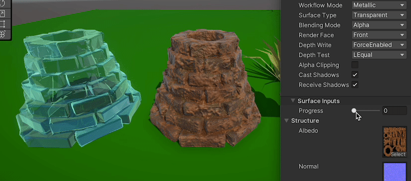
No idea how that component handles materials
will test with a sprite and see
@grizzled bolt metalllic/smoothness reflections work just fine with a sprite
so most likely due to the svg thing
Hi, how can I make it so a texture always looks at the camera, kinda like a billboard, but not the mesh itself?
Use screen position as UV input for the texture
thanks
how can i combine both the tiling/offset thing and the screen position?

Screen position -> UV port on Tiling And Offset -> UV port on Checkboard
oh ok thanks
Hi all, quick question, i have a bunch of textures similar to the one attached, but each one has a different 'darkest' level (ie, the darkest grey on this one is lighter than some of the others, or darker). Is it possible with shader graph to 'normalise' any texture I plug in, in the inspector, so that they all share the darkest dark colour and lightest light colour when processed through the graph?

It's a bit Kludgey but seems to work.

No
Such normalization would require checking all the pixels of the texture which shaders cannot do
It'd be for the best to correct the brightnesses in an image editing program
It'd also avoid having to have those extra properties in the shader
Okay, thanks for the reply. I've decided to go another route. 🙂
Hey guys, for some reason when im building my game for android, my fullscreen shader isnt enabled for some reason (im using URP) does anyone know why?
The build might be using a different Renderer asset (one without the fullscreen pass), as it can be overridden per Quality setting.
The project template usually creates 3 sets of URP & renderer assets iirc.
ooh i see
yea lemme configure those
thanks fixed it
Hi there, I want to create a black and white effect for a 2d game and when an area of the screen is clicked on, a circle around the cursor has colour restored to the screen - I dont whether id use a shader for this or how that would work, i dont whether that would be a shader or something else?
^