#archived-shaders
1 messages · Page 60 of 1
You can't use instancing to draw different meshes, or at least not trivially.
I see. So there is not instancing in unity in the way I want it to?
Sorry, but gradient internally is an array of 8 values (8 color and 8 alpha) which is sampled in a loops. Maybe different versions of shader graph have different implementations, but v14 uses value array.
Yes, but the gradient struct is directly declared and populated in the shader code, not in the shaderlab properties, where, like I said, there is not gradient type.
One could argue that it could have been done using 16 properties collapsed into one in the inspector, but that's not how it has been done, and this is why gradient can't be exposed in the inspector.
Thanks for the clarification.
Any tips on how to manage this? I need to make sure the circles are see through or the squares/5sided one. Is there a shader solution for this?

it would be easiest if you got texture on them with outsides being white and inside being dark so you could connect to alpha and easily get it to be transparent
They are 2 separate entities, but maybe I can overlap it like above and then make the ends black 🤔

I've got a simple shader going on that is applying a layermask to show two different textures at once. For some reason, when I swap between using a mask I made in photoshop (left) with a mask I made using shader graph nodes (right), I get this bluish hue. anyone know why?


Oh I just noticed that the texture 2d is a square but the thing I made is a circle, anyway to make the circle a square lol (idk if the shape indicates 2d vs 3d or something)
The mask has negative values. Can use a Saturate node to clamp it between 0 and 1 before lerping
oh, thanks!
Can also change the preview type in the node settings (tab of graph inspector window)
You solved all my problems, thanks!
A scrolling wave texture is a good start
You would animate its UV with a acrolling coordinate with the _Time property or such
Don't know if this is more appropriate for the Unity or the Blender server so... I'll just put it in both.
There's a model I'd like to use in Blender over Unity given it's what I'm used to and such, but there is a specific shader that makes it work that I can't import from Unity to Blender. It's the VRC toon shader by Poiyomi.
Any solutions or help?


Just showing off, this is my first dithering shader + outline shader. Not perfect but I learned a lot.

Hey, would anybody know how i can add to vornoi (self made min distance on point array) some math to allow me of smoothing out nearby points? With normal implementation I'm getting flat seams between those.
Something similar to attached smeared example.

You can look up shader smooth min/max. Here are some examples:
https://www.shadertoy.com/view/Ml3Gz8
https://www.shadertoy.com/view/4dtXRn
https://github.com/glslify/glsl-smooth-min
Thank you a lot
I've got a very basic question which I can't seem to figure out. I just want to overlay the lower node to the upper one, considering black as transparent. How can I do that?

There is a Blend node that should do the trick.
None of its options did it for me really
Have you tried using Max?
That's another node
Using Max makes the upper one cover the lower one. Using Min makes the lower one cover the upper one because the black part isn't transparent. Isn't there some sort of standard way to treat black as transparency ?
Do you mean only the rgb(0, 0, 0) color, or the darker the color, the more transparent it is? So grey would be 50% transparent?
You could try using the Replace Color node to replace black with a transparent color. That makes it similar to chroma keying/green screening.
I want it to be the darker, the more transparent but I also forgot that my colors are in grayscale as well so that might be an issue
The fuzziness parameter in Replace Node should let you choose the right value.
Nevermind, I'll see if I can rework the shader a little bit as perhaps this is not the right way of doing things. Thanks for your suggestions!
If I have the depth texture mode set to depth normals how do I sample the depth normals in shader graph I see no node for it
Hello guys i have one question i was trying to follow this video
https://www.youtube.com/watch?v=RMt6DcaMxcE&ab_channel=NedMakesGames
But i got stuck because there is a blitmaterial feature scrip and its outdated i cant get it work with RTHANDLES (https://github.com/NedMakesGames/RendererFeatureBlitMat/blob/master/Assets/Rendering/Desaturate/BlitMaterialFeature.cs)
Isnt there a better way to do this outline thing when we have the Full screen shader graph now ?
✔️ Works in 2020.1 ➕ 2020.2 ➕ 2020.3
🩹 Fixes
► I made an editing mistake around 1:30. Please note, you need to place the outline material into the material field of the BlitMaterialFeature. It should not be empty after this step. Sorry about that!
► At line 35 in EdgeDetectionOutlinesInclude.hlsl, the sixth entry in sobelSamplePoints should be f...

GitHub
Contribute to NedMakesGames/RendererFeatureBlitMat development by creating an account on GitHub.
Yea, should be able to do the edge detection calculations in a Fullscreen graph and use the Fullscreen Pass Renderer Feature rather than this blit one
How do i get the Depth texture though ? i cant wrap my head around this
Do i use the URP sample buffer somehow ?
Should be able to use the same shader graph setup with custom function like in the video, just with the Fullscreen graph instead of Unlit
Yeah but the in the video he has the Texture input _MainTex -> Sampler -> Blend and this is not giving me results
Ah okay, use the URP Sample Buffer "Blit Source" instead of the MainTex -> Sample Texture2D
Tried doing that but nothing really changed


The result still no outlines

Its doing some weird stuff ..
I think you want the Pass Index to be pass 0 here (DrawProcedural). The fullscreen pass uses a fullscreen triangle, not quad/blit iirc.
Changing that doesnt have any immediate effct but i changed it
Values are probably quite large here too, the video uses something like 0.01 for thickness and 1 for others
i know but it does nothing ...
I had to overshoot the values to even see a change


Its just darkening the whole screen 😄
How do specular highlights work on the URP lit shader? For instance, see the picture attached. How is it that on a single face I am able to get such a result? My attempts with blinn or with phong seem to yield uniform results across faces.

I made a shader that adds an outline to any 2d sprite and removes the parts of the outline that intersect with another outlined object, but it has two passes and I need to make it URP-compliant (URP does not allow you to use multipass shaders for some reason). I already have a version of the outline shader that does have one pass, but I can't manage to get the non-intersecting outline part working because of the way I implemented it in the multipass shader (I used the stencil buffer, ref 1 comp equal pass incrsat fail incrsat). Can someone help me with getting this working with a single pass?
Here's the code:
Single pass
Multi-pass (This one does work as intended)
This is the intended result (Using multipass)

Could somebody advise me on where to begin / which terms to search for to achieve such a shader effect (URP) ? a sort of dot-effect with glowing emission. like LED meets hologram. Thanks!

You could make some texture for the LED dots, and multiply that by whatever color you want it to be, and put it on a transparent material with additive blending
😁 thanks! i knew i was overcomplicating things. @karmic hatch and what about the blur emission thing?
Bloom, it's a standard post-processing effect
Always makes bright things look better
in URP ? 😄
Yep!
Hey everyone. Are there any tutorials to make a procedural tiled shader like this for a sprite?

Still struggling to understand how default specular highlights are implemented. Any idea?
step(0.5, fract(dot(stripe direction, UV*stripe frequency)))
(really, stripe direction and stripe frequency can be included in the same Vector2, but it's easier to change a single value for stripe frequency than to have to change both components of stripe direction at the same time, in the same way)
Or even simpler: how do I make a shader for a tiled sprite? Like, to make a shader tile itself if the sprite is in Tiled mode?
Multiply the UVs by some factor and then fract them before passing them through the rest of the shader
Phong shading is probably the simplest to understand.
That works but how do I get the size of the sprite to decide on the number of tiles?
The sprite is tiled based on its size in the game world
@low lichen Yeah, I've tried blinn and tried phong. With both of them, faces are uniform. With unity's default, I get a result like this.

calculate it in the shader from the object scale
I'm trying to understand how they are able to get a result such as this
they shouldn't be uniform; the specular reflection depends on the direction of the light relative to the face, as well as the view direction relative to the face, and that latter one is why the specular highlight is localised
are you using the camera forward direction or something?
I'm using the camera node direction output in shadergraph
Let me process the above real quick
Right, but it is relative to the face, and it is why everything that shares the same normal will share the same highlight value, no? @karmic hatch
you want to use the view direction, not just the camera direction
they are different unless the camera is orthographic
oooh I see how this makes sense
hang on
@karmic hatch Yeah, that was it. Thank you vm
np :)
Almost it, but I need a shader for the UI, and it doesn't use scale to change the sprite's size. The scale is always 1. Can I somehow get the size of the UI element into my shader?
@karmic hatch 😄

w/ bloom!

ill try to benchmark a bit on mobile before i get too happy about it 😂 thanks a bunch!
hi , i wanna create in fragment shader the same function as

does anyone knows how to do that
Exact syntax varies a bit between render pipelines. But in short, sample _CameraDepthTexture and put it through LinearEyeDepth function.
it's not working
L : is the output of Scene Depth - Eye
R : LinearEyeDepth(SAMPLE_DEPTH_TEXTURE(_CameraDepthTexture, (OUT.screenSpace.xy / OUT.screenSpace.w) ));

im using URP
@regal stag any ideas ?
How are you calculating screenSpace?
o.screenSpace = ComputeScreenPos(o.vertex);
Is that after calculating o.vertex?
yes
How is screenSpace defined in the output struct? float4?
yes float4 screenSpace : TEXCOORD1;
Then I'm not sure why it's isn't the same
have you tried it on ur side ?
For URP you'd also usually use this include https://github.com/Unity-Technologies/Graphics/blob/master/Packages/com.unity.render-pipelines.universal/ShaderLibrary/DeclareDepthTexture.hlsl
But with HLSLPROGRAM, not CGPROGRAM & UnityCG.cginc. What you have should still be equivalent though.
thanks I'll take alook at it and try to figure out what is wrong
I've thought about this more, the result here might make sense if one of these outputs is writing depth while the other is not.
You'd usually only use the Scene Depth node in a Transparent shader graph (Tags {"Queue"="Transparent"} and ZWrite Off in code) - to get the depth of objects behind it. Unless the background is a plane with a grey material, there's no objects behind to get the depth of, so difficult to tell if it's working.
If you just need the depth to this object itself there's other ways of handling that, like -viewPos.z
i'm not sure what -viewPos.z represents? its unidentified for me
btw, are you the owner of this https://www.cyanilux.com/tutorials/depth/ ? that looks quite interesting for shader graph
A big post explaining everything about Depth : Depth Buffer, Depth Texture / Scene Depth node, SV_Depth, Reconstructing World Position from Depth, etc.
Yes that's my article. -viewPos.z represents the depth to the fragment being drawn, it's the first section in that.
Whether you want that or the LinearEyeDepth(SAMPLE-etc) depends if you want the depth to the mesh being drawn or the scene behind it.
I just want the same effect that this node does when it's on eye sampling to work on URP fragment shader @regal stag
not sure, why it's kinda hard to find the code that generated it in fragment shader
That should be equivalent to the code you already have
But results will vary depending on the graph/code is set to render in the opaque queue & ZWrite vs transparent queue & ZWrite Off
You're meant to only use it in the latter, so you'd want to make sure your code has Tags {"Queue"="Transparent"} and ZWrite Off under the Pass
queue set to transparent and zwrite is off but the results is more like sceneDepth raw/linear01 than eye , i'm looking into it
i do have those and
Is there a way to use Shader Graph on UI element without setting canvas render mode to "Camera"'?
so I followed an old tutorial to manipulate colors of a sprite, and everything works except for the end, because unity changed from masters to fragments and vortexes. endless amount of searching doesnt bring up anything. how can i make the main preview show my sprite?

im using a sprite lit shader graph
and universal render pipeline
what does this do

the output seems to be just black or no colour
i assumed it was the world normals much like you can get depth values from scene
but doesnt seem to be
It is, but only if URP generates the camera normals texture. A renderer feature can tell URP to do that, like the SSAO one or a custom one that uses ConfigureInput(ScriptableRenderPassInput.Normal);
yeh i have that

i presume this is all i need to enable it ? right?
@regal stag or do i need to do something extra?
the output however is just black or regular scene colour

I'd also assume that's all you need, but I haven't really used the NormalsSource on the URP Sample Buffer node before
Frame Debugger window might give some clues to see if texture is generated and used
A magenta Main Preview usually means the shader is not suitable for the current pipeline. Check that you have URP setup correctly (URP asset assigned under Project Settings)
oh ok, how do i set it up properly
i followed a tutorial step by step, i know it was a bit old but idk what else to do
oh wait nvm figured it out
thats weird how the tutorial didnt mention it but!
well now my main preview is just blank
wait i figured that out too, tysm
whats the difference in these two options for scene depth

would would raw be ? and is eye depth essentially world units relative to camera?
hi- another question: how would I do URP with spritesheets? whenever i try with a spritesheet it compresses it a bunch in the render pipeline area which makes it hard to pinpoint colors because its so compressed
The raw value is a float packed/encoded by unity. There's shader macros for dealing with it, but mostly you'll want either eye depth or 0-1 depth. Think of it as "Unity encodes the depth the way it wants to, it can change, and I don't care I just want the 'regular' depth not the raw encoded depth." Usually.
'Pixel values in the depth texture range between 0 and 1, with a non-linear distribution. Precision is usually 32 or 16 bits, depending on configuration and platform used. When reading from the Depth Texture, a high precision value in a range between 0 and 1 is returned. If you need to get distance from the Camera, or an otherwise linear 0–1 value, compute that manually using helper macros (see below).
From https://docs.unity3d.com/Manual/SL-CameraDepthTexture.html

so would i use that to get world units ?
bit confused how i would actually convert 0 - 1 to a world value
Try the eye-space one. Eye-space is view-space and should be in world units IIRC.
I dont understand , nobody seems to know how to do the simplest ( ScreenPosition -Raw ) node in fragment shader..
it's literally just that

ex: I found this detailed code online that calimed it has the same effect, but it's not at all https://gamedev.stackexchange.com/questions/186226/understanding-screen-position-node-in-unity-shader-graph
struct v2f {
    float4 vertex : SV_POSITION;
    float4 screenPosition : TEXCOORD0;
}

v2f vert (appdata v) {
    v2f o;
    // This is effectively a multiplication by the Model-View-Projection matrix,
    // taking the vertex from object space to clip space (before the perspective divide)
    o.vertex = UnityObjectToClipPos(v.vertex);

    // This copies the information from the "special" vertex position semantic that in
    // older shader models we can't read directly in the fragment shader. Copying it out
    // lets us interpolate it and read it just like any other texture coordinate.
    o.screenPosition = o.vertex;
    return o;
}

fixed4 frag (v2f i) : SV_Target {
    // Here we get the per-pixel value, after it's been
    // interpolated between the three vertices in the triangle.
    float4 shift = i.screenPosition;

    // Ordinarily, 0,0 would be the center of the screen, but Unity calls
    // that mode "Center" not "Raw". In Raw mode, the center of the screen is 0.5
    shift.xy += 0.5f;
    return shift;
}
here is the results of that code compared to the node i mentioned earlier
the white ball is the node, the black one is the code
completely different results.
I dont understand , how is this so hard that everyone gets wrong ?
the unity shader graph manual stated that the generated code of that node is just this

but when i output screenPosition as mentioned , it's not the same either. it outputs another black ball
The "screen pos" of a fragment is going to be passed from the vertex stage to the fragment stage via interpolators. There's a shader semantic "Position" that ties a value to the struct so the GPU can use it during rasterization (and it does a 'perspective divide' where it is divided by the .w component).
Now, starting there, you seem to be asking about "raw" mode. This is the screen position in clip-space BEFORE the projection divide happens during rasterization. So it is passed from vert() to frag() unchanged. And that's what your code sample circled in red above shows.
As far as "I want to match some random code on the internet to Unity" IDK what your motivation is, but you have to have apples to apples comparison. Note that there's a "center" value that is available in the node too.
https://docs.unity3d.com/Packages/com.unity.shadergraph@17.0/manual/Screen-Position-Node.html
See the last comment in your code sample, and try using the "center" option on the node.
1 - does that means I should multiply the screenposition with w component screenPosition * screenPosition.w before i return it ?
2 - if the center position for RAW is float2(0,0) , then i think we should ignore it, correct ?
I have no idea, I'm not following you very well.
What do you WANT to have for a value?
Your "2" is ....the center position for RAW is .5, .5
So they're using "screen position" as lower-left = float2(0,0).
My explanation was bad due to unity's terminology, sorry.
i still dont undertand how to do this
here is the code im trying
float4 g = OUT.screenSpace * OUT.screenSpace.w;
g.xy  = g.xy * 0.5 + 0.5;
return g;
im still getting a black ball
It's a divide, not a multiply.
What are you trying to get?
What values do you want?
Unless you're trying to "un-divide stuff".
oh , i thought it was divided when it moved to frag function , so i thought to reverse that to raw i need to multiply it
anyway when i divided it i got a similar results to default screenposition but not raw
What do you want to have?
Do you want (0,0) to be the center of the screen, or the lower left?
i want it just like raw mode
at the lower left corner of the screen. This mode is useful for projection.
If 0,0 is center, use the center option on the node. If you want it to be lower-left, use the raw value.
Why can't you just use the value from raw node?
as far as i know it doesnt generate a fragment shader rather a surface shader
yeah not using shader graph
Oh. OK. So I'm starting to figure out what you're doing...you're using shader graph's examples for sample code, but are hand-writing a shader. And you have questions as to what the SG sample code is about, and why it's different from something on the internet, but you also want it to work in your custom hand-written shader.
yes pretty much
but yeah i didnt look for the inter fist, i tried to follow the descriptions and it work several times so i looked for answers online , so yeah pretty much
You want what as a result?
- (0,0) in lower left and (1,1) in upper right for the fragment?
- (-1, -1) in lower left, (0,0) in center, (1,1) in upper right for the fragment?
- (0,0) in lower left, (x, y) in upper right for a pixel position of the fragment?
well, based on the description of RAW mode here >> https://docs.unity3d.com/Packages/com.unity.shadergraph@17.0/manual/Screen-Position-Node.html
it says
Raw - Returns the raw Screen Position values, which are the Screen Position values before the clip space position W component is divided out. Position float2(0,0) is at the lower left corner of the screen. This mode is useful for projection.
so that is what i'm trying to achieve (0,0) but in fragment shader not surface shader nore shader graph
They seem to be doing something a bit weird.
They're internally computing that screen position somewhere else and you're not seeing the code to compute it, you're just seeing the sample code to "return the value". They're calling the normal clip-space value NDCPosition in their code (also not shown except as a return).
So let me go back and look at your code, sec.
thx for doing that ❤️
OK, in your sample code, o.screenPosition is the normal clip-space values that are called NDCPosition in the shader graph code. It is what you get with the "Default" option from shader graph's node.
It's NOT the "raw" clip-space value, which isn't in your code sample, and they don't show the calc for "ScreenPosition" the SG code. I'd have to check a sample of the shader graph code to confirm this. So if I read it right, it's a bit confusing. They're talking about a "raw" screen position, probably lower-left=float2(0,0) based, not a raw "clip-space" value. Oy.
Did you try "default"?
wait, it looks like they did it after dividing it out.
sigh
shader graph fenerated code (RAW)
SurfaceDescription SurfaceDescriptionFunction(SurfaceDescriptionInputs IN)
{
      SurfaceDescription surface = (SurfaceDescription)0;
      float4 _ScreenPosition_297c7762a2ef4afd8e33b288ccdbd47d_Out_0 = IN.ScreenPosition;
      surface.Out = all(isfinite(_ScreenPosition_297c7762a2ef4afd8e33b288ccdbd47d_Out_0)) ?            half4(_ScreenPosition_297c7762a2ef4afd8e33b288ccdbd47d_Out_0.x, _ScreenPosition_297c7762a2ef4afd8e33b288ccdbd47d_Out_0.y, _ScreenPosition_297c7762a2ef4afd8e33b288ccdbd47d_Out_0.z, 1.0) : float4(1.0f, 0.0f, 1.0f, 1.0f);

return surface;
}```That's not it, it's already calced before thtat as it comes in via the IN. struct.
output.ScreenPosition = ComputeScreenPos(TransformWorldToHClip(input.positionWS), _ProjectionParams.x);
OK, that's how the calc it and what macros they used in the new pipeline.
You can look for NDCPosition too, if you care.
there is no mention for NDCPosition in the raw code, let me check the default
 output.WorldSpacePosition = input.positionWS;
    output.ScreenPosition = ComputeScreenPos(TransformWorldToHClip(input.positionWS), _ProjectionParams.x);
SurfaceDescription SurfaceDescriptionFunction(SurfaceDescriptionInputs IN)
{
      SurfaceDescription surface = (SurfaceDescription)0;
      float4 _ScreenPosition_297c7762a2ef4afd8e33b288ccdbd47d_Out_0 = float4(IN.ScreenPosition.xy / IN.ScreenPosition.w, 0, 0);
      surface.Out = all(isfinite(_ScreenPosition_297c7762a2ef4afd8e33b288ccdbd47d_Out_0)) ? half4(_ScreenPosition_297c7762a2ef4afd8e33b288ccdbd47d_Out_0.x, _ScreenPosition_297c7762a2ef4afd8e33b288ccdbd47d_Out_0.y, _ScreenPosition_297c7762a2ef4afd8e33b288ccdbd47d_Out_0.z, 1.0) : float4(1.0f, 0.0f, 1.0f, 1.0f);
    return surface;
}
wow there is no mention for NDCPosition at all, strange
OK, so:
float4 _ScreenPosition_297c7762a2ef4afd8e33b288ccdbd47d_Out_0 = float4(IN.ScreenPosition.xy / IN.ScreenPosition.w, 0, 0); takes the output.screenPosition value (which looks like it is not divided by yet) and stores it in some work-variable after manually doing the perspective divide (note the divide by .w), and they check for validity and they return a 1 in the .w component because it's after the divide.
I made it look more simpler , by changeing _ScreenPosition_297c7762a2ef4afd8e33b288ccdbd47d_Out_0 by g
float4 g = float4(OUT.screenPos.xy / OUT.screenPos.w, 0, 0);

                if (all(isfinite(g))) {
                    return half4(g.x, g.y, g.z, 1.0);
                }
                else {
                    return float4(1.0f, 0.0f, 1.0f, 1.0f);
                }
its not right yet..
So in your code, if you wan the same value as "raw" you'd use:
SurfaceDescription SurfaceDescriptionFunction(SurfaceDescriptionInputs IN);``` (copied from your partial code-clip above).
````o.screenPosition = float4(o.screenPosition.xy / o.screenPosition.z, screenPosition.z, 1.0f);```
I think.   If that's what you want.  And it's using the new pipeline macros.
OK, I'm out of date on the current version of "your code"that sounds great but ComputeScreenPos(TransformWorldToHClip(input.positionWS), _ProjectionParams.x); this raises an error TransformWorldToHClip is undefined even thought i have those included
#include "HLSLSupport.cginc"
#include "UnityCG.cginc"
¯_(ツ)_/¯
I get it. You're trying to hand write shaders in the new pipeline without a of docs and you're using SG as a code generator and it's giving you fits. This is where I usually bow out because I don't hand-write stuff in the new pipeline, I'm waiting for the new shader block system and/or using SG. So I let others deal with it.
BUT you should be able to find the right include somewhere.
And BTW, shader graph code it a bit convoluted and that's what is throwing you off, and back in the "old days" it was pretty direct as to what you'd code, but SG is doing some thing as a code generator that you'd probably not do by hand.
@meager pelican thanks for the help , i will look into it a bit further , its kinda weird how things are not as clear as it used to be , but as long as we have access to the code, we could learn something
but thanks a lot for ur help ❤️
balls
yooo ive made an outline shader in shader graph
im using a bolean to programatically turn it on/off
its for a card game, so when you mouse over a card the outline comes on
probably is I want a really quick fade in/fade out on the outline
like 10ms
but right now the bolean is just a bineary
i was hoping they were was a simple function I could use to like slew the bolean
i can fix this ?
does anyone knows how to get (position of the pixel on the screen) using shader fragment ?
how would I do URP with spritesheets? whenever i try with a spritesheet it compresses it a bunch in the render pipeline area which makes it hard to pinpoint colors because its so compressed
Im started to think that there are things that cant be done in shader fragment, I've been trying almost every tip i find online to do a similar effect as what shader graph screenPositionRaw does
This chat is full of questions but no answers
I swear
I will become a shader pro
And help you all one day
Same
Like I just wanna put my shader on a sprite sheet bro why’s it gotta compress

yes they said that on the document but they didnt say the full function of ScreenPosition, im trying to mimic the same thing in fragment shader
Does anyone know if Unity included a pre-made shader graph for the new water system and if so where it is? the HDRP package no longer has Water Samples in it, was going to check there for the graph....

Use a Float property instead of a boolean. Set it from C# using material.SetFloat, lerping a value from 0 to 1 (or 1 to 0) in Update function or in a Coroutine. Can probably ask in a scripting channel for more help on that part
https://docs.unity3d.com/ScriptReference/Material.SetFloat.html
There should be settings near the bottom of the texture importer to adjust compression
https://docs.unity3d.com/Manual/class-TextureImporter.html
If you're using Replace Color node there may also be alternative methods
Change your spritesheets filter to Point and remove mipmaps
to get the best quality
and dont compress at all
Im not sure what mipmaps are but the filter is point, compression none
It looks perfect on scene it just gets squished in the texture2D in render pipeline
ah ok, just checking, its probably what Cyan suggested then
Unsure what you mean by this
Do you mean in shadergraph previews and such? That's just how those work.

yeah like it squished
so i cannot replace color
It's squished because previews will shows the whole texture while in scene it's applied to a mesh with specific UV coords, but it shouldn't affect the colours.

Well, maybe the preview itself has slightly different colours due to bilinear filtering. But you should be able to colour-pick from other sources
Well for anyone interested the water scenes are apparently in the environment sample set but it's currently just not listed under the HDRP samples lol

well see if i color pick the eyes
the eyes are all different colors cause of the compression
so when i color pick to replace, it will only do for that one shade of yellow
wdym color pick from other sources
Is it possible to use the colour picker to select colours from a different window rather than the preview, like the texture opened in paint/photoshop/etc
Alternatively you could use a separate texture with only pure red/green/blue to mask the parts you want to recolour - would be more accurate than the replace colour node. Something like the examples here & the "Mask Texture" section after - https://www.cyanilux.com/tutorials/color-swap/#tint-color-channels
well it wouldnt work with spritesheets still cause it compress. this is me replacing the color of the eyes to the color red, i colorpicked from the texture preview in the inspector instead of the one in the URP

those compressed offcolor yellow bits still stuck
Are you sure the texture is using Point filter mode, this looks like Bilinear filtering - or different colours baked into the texture itself, perhaps as a result of resizing?
100% if i just use 1 sprite and not the sprite sheet it works
Hey, sorry for a super long delay, just realized I forgot to say thanks for that, it does exactly what I need 😄
I've just checked it a few days later, went to do other stuff and then forgot
Does the sprite sheet (atlas?) have it's own filter mode perhaps? I'm not that familiar with 2D components/assets
idk what you mean by that, it's just a regular old image
see when i do it with 1 sprite URP doesnt compress it together like that
cause its big enough to fit in the preview
Hmm.. I thought you might be using the Sprite Atlas thing to combine smaller sprites but nvm. Is the texture a power of two size? Unity might be trying to resize it, unless you tick Non Power of 2 on the texture importer.
not sure let me tick it and try again
Make sure you close and reopen the graph after as well to refresh the texture
yeah i cant find that setting
iirc it's under the Advanced heading/dropdown in the texture importer

It's not there, but i think i found the issue
i was comparing the single sprite i imported with the same version of it in the spritesheet
and the spritesheet was in noticably less quality
Ah so it's the texture data itself which is the problem
i have no idea why, they both look identical quality on my computer
Or is it only worse quality after imported into unity?
Is it maybe the Max Size setting in the texture importer? I think the default is 2048. But if the texture itself is larger, unity might be scaling it down
height is 662 and width is 2802
That might be it then
gosh why is it soo hard to find the actual code that creates the ScreenPosition(Raw) just like shader-Graph
it has to be at most 4 lines of code.
yet I cant find it anywhere!!
and I dont think i am not knowledgeable enough to came up with it myself, my exp in shaders are quite limited.
Afaik it should be equivalent to doing ComputeScreenPos(UnityObjectToClipPos(v.vertex)); in vertex shader and passing the resulting float4 to fragment
Well, those are the CGPROGRAM / UnityCG.cginc functions, intended more for the Built-in RP
but when you actually compare apples to apples, its not the same at all, its quite different..
@regal stag the more yellow ball is the one with this code ComputeScreenPos(UnityObjectToClipPos(v.vertex)); , notice if I returned the whole float4 it makes the ball just black , so i had to make it like return float4(OUT.computeScreenPos.xyz,1);
the other one is just shader-graph screenPosition(RAW) outputting float4 directly.
When they overlapped there's some dark blue which is a bit odd, there's probably some different blending going on
i honestly have no clue, i really dont know how to do it right, i surfed the internet for the past 2 days, i couldnt find anything
not sure why a simple code like that is so hard to find
I'm new to shaders, i have like few weeks exp, i cant till what could be the reason , this is beyond my experties.
If you're returning 1 alpha in the code is the graph also using 1 for the Alpha port?
this is how it looks like with return OUT.screenPosition;>> (COMPLETELY DARK) instead of float4(OUT.screenPosition.xyz,1);

and here is how my sahder graph looks like >> the other white ball

This setup is wrong, connecting a Vector4 output to a Float port will truncate the vector, taking only the first (Red) component. You want to use a Split node to take the alpha (A) channel before connecting to the Alpha port.
like this ?

Yes, is this the same when comparing to return OUT.screenPosition; now?
I'll let u be the judge of that @regal stag
code is outputting return OUT.screenPosition; ( dark ball )
any chance for u to test it on urside ?
maybe u can get it to work ?
This is equivalent - https://pastebin.com/0q9Tf0Mc
GOSH!! it worked!!, thank you soo much !!
do u have anyidea what i was doing wrong ??
u know what, at this point im so relieved i dont wanna even do anything today good night 😄
thank you so much ❤️
At a guess I'd say the Blend line. I copied it from the generated shader graph code to make sure it was the same as the alpha blending from there.
I'll pay attention to that next time , gosh what a waste of time 😄 , i spent 2 days on this lol
thank you for ending my misery 😄 ❤️
Hi all, I switched my 2d project to urp, but I have a issue with shadergraph, I have no preview (for 2d shadergraph & 3d shaders)

Generally I think i installed urp properly, I created the pipeline renderer asset and the 2d renderer, and added it to the player build settings
How to make a sprites-default in shader graph? I am using sprite shape with different sprites for corners n stuff, but idk how to pull the texture directly from the sprites instead of always needing to put the sprite directly onto the material...
I selected create new custom material on the HDRP water system and this is the shader graph I got for it.....is there no way to route anything to an emissive output?

i cant select HDR color as an option for any colors in the system itself either...
Might just be bugged. I'd recommend saving the graph (Save Asset in top left) and previewing in scene view by applying the material to an object.
The _MainTex texture reference is usually where the SpriteRenderer component passes the sprite texture into
I haven't used the HDRP water system, but can you add the Emission block to the Fragment output? Need to right-click on ones of the lines that appear between blocks or at the end and select Create Node, like this

If after adding it's greyed out that means the active target won't use it though
Nice suggestion....unfortunately 😦

@Cyan any idea why is SG using TransformWorldToHClip() when you can just use ComputeScreenPos(o.vertex)? Post ^^.
He was using SG to get samples of how to hand code in the new pipeline.
Can't wait for block shader system....hopefully with at least some docs.
Or object2clipPos or whatever
It's the same sort of thing, ComputeScreenPos just needs a clipspace input. In a handcoded shader you easily have access to the clipspace vertex shader output (that you calculate through functions like UnityObjectToClipPos / TransformObjectToHClip).
I imagine SG is just a bit messier as it has to generate all the code. But I think the compiler might optimise it?
I phrased it wrongly....What's the diff between UnityObjectToClipPos and TransformObjectToHClip?
I get that ComputeScreenPos wants a clip-space value.
The first is more for the Built-in RP. It's in UnityCG.cginc include. The latter is in the render-pipelines.core ShaderLibrary (so only available if using URP/HDRP includes)
I mean, it's infuriating! Oh well. At least that explains why the includes didn't work. But why have a different name for the function just to make it harder to transition to the new pipelines?
thanks.
As always.
Hello, I'm following a tutorial that allows me to create shadows for my 2D sprites in a 3D space. The result is that the shadow created fits the original sprite by the sprite itself is now a purple shape (not possible to render I assume) is there a way to fix this? (The tutorial uses a standard surface shader)
Before and After the material change

Code used to create this shader

Is there an easy way to get sprite dimensions inside the shader? I want to set certain pixels to different colours depending on their position relative to the edge of the sprite but not sure how to get the sprite stuff relative to the uv coordinate
shader is pretty simple for now
{
    Properties
    {
        _MainTex ("Texture", 2D) = "white" {}
        _StatPercent ("StatPercent", float) = 0.5
    }
    SubShader
    {
        Tags
        {
            "RenderType"="Transparent"
            "Queue"="Transparent"
        }

        Blend SrcAlpha OneMinusSrcAlpha

        Pass
        {
            CGPROGRAM
            #pragma vertex vert
            #pragma fragment frag

            #include "UnityCG.cginc"

            struct appdata
            {
                float4 vertex : POSITION;
                float2 uv : TEXCOORD0;
                fixed4 color : COLOR;
            };

            struct v2f
            {
                float2 uv : TEXCOORD0;
                float4 vertex : SV_POSITION;
                fixed4 color : COLOR;
            };

            sampler2D _MainTex;
            float4 _MainTex_ST;

            v2f vert (appdata v)
            {
                v2f o;
                o.vertex = UnityObjectToClipPos(v.vertex);
                o.uv = TRANSFORM_TEX(v.uv, _MainTex);
                o.color = v.color;
                return o;
            }

            fixed4 frag (v2f i) : SV_Target
            {
                fixed4 col = tex2D(_MainTex, i.uv) * i.color;

                return col;
            }
            ENDCG
        }
    }
}```Hmmm, float4 _MainTex_TexelSize; would give you (1/width, 1/height, width, height) of the sprite texture - the first two components being the size of a single texel.
(If the sprite is part of a larger sprite sheet / atlas that's going to be the whole atlas, not just a single sprite though)
Why not just stuff the original non-transformed UV into the zw component and make the UV info a float4?
That could work... can you elaborate?
Is there a shader error in the console / inspector on the shader?
Also what render pipeline are you using? Note that surface shaders are only suitable for the Built-in RP and won't work in URP/HDRP.
In the vert()
o.uv = float4(TRANSFORM_TEX(v.uv, _MainTex).xy, v.uv.xy);
where o.uv is in the v2f struct as a float4 instead of a float2.
No compiler errors from the console, and in terms of pipelines, URP
just make sure your references are to i.uv.xy or i.uv.zw where you want them. Or use separate variables (better to pack them into a float4 though, to save on interpolators).
IG let's change the pipeline and see what results I get
Then yeah, you'll either need to switch to Built-in RP or find a different shader as surface shaders are not supported in URP. Could use the URP Sprite-Lit as a base maybe : https://github.com/Unity-Technologies/Graphics/blob/master/Packages/com.unity.render-pipelines.universal/Shaders/2D/Sprite-Lit-Default.shader
But add in your own ShadowCaster pass (the URP/Lit.shader in the folder up might give an example of that)
So say I want to compare the y value of the original uv to the height of the sprite, I'd be looking at i.uv.w and _MainTex_ST.w ?
I'll see what I get a report back if any further problems arise - thanks
I think since it's a SpriteRenderer I'm not sure it gives you access to override the mesh uv data. (Though not 100% sure, I don't tend to do 2D)
I'm not too fussed about the method used, as long as I can determine (for example) if this pixel is 70% of the height of the sprite
Depends on what you're doing, I'm unclear about " I want to set certain pixels to different colours depending on their position relative to the edge of the sprite but not sure how to get the sprite stuff relative to the uv coordinate".
The uv is a % of the size. It's transformed by the tiling/offset values by that macro.
The original uv is the original % without tiling/offset. But its more of an "abstract concept". So if you wanted a grey scale at the center and color at the edges of the sprite, you could lerp between the logical (0,0) of the center of the sprite and the edge of the sprite by doing something like
float4 texBW = ...blah...
float myPctGradient = abs(i.uv.zw - 0.5) * 2.0;
float4 result = lerp(texBW, texColor, myPctGradient);```Well, if the original uv works, the zw would be 0.7. (well, the w would be)
But see Cyan's comment above.
Oh man ok, I had the space of the UV wrong in my head for some reason
I can just totally use the UV value as it's between 0 and 1
IDK that it works though. See what Cyan is saying above about sprite renderers.
it does :)
I'd assume if you have to use the TRANSFORM_TEX macro, that the original uv is "normal" untransformed.
It's _MainTex_TexelSize you want btw, if you don't want to hardcode the size of a pixel in the texture, I wrote the wrong reference before
Thanks both
My shader experience is sorely lacking... give me a second and I can show you what this was for
<img removed>
There is an issue though - if I want this to work with more than one resource, calling SetFloat on the material sets both of them - is there a way I can instantiate them on runtime such that they use different instances so I don't need to duplicate the material?
Using GetComponent<SpriteRenderer>().material should automatically create an instance
Assuming it's a sprite renderer and not UI
Nah I'm in UI atm
so it's Image.material
I guess I could just get it, copy it then set it back right?
Then you might need to duplicate the material yourself. img.material = new Material(img.material); should create a clone
cheers
Ideally you keep a reference and Destroy it when it's no longer needed as well (e.g. in MonoBehaviour.OnDestroy)
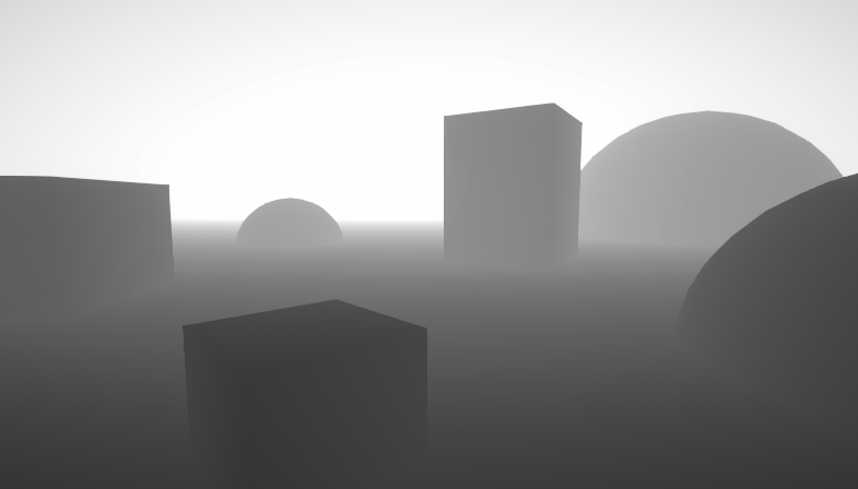
Hello, i saw a GDC video about the rendering for the game called Inside.
i was wondering if it's possible to do something similar with the fog?
They have a linear fog but it is clamped at a maximum so lights still show through the fog


how could i fix the flickering issue with the skybox?
if i switch the render queue to transparent then instantly i get lots of draw calls increasing , as it is for mobile , i was curious about another solution
thanks in advance
bump)
So I found out, in the Game window, if I look through the occlusion mesh instead of the left eye, I see a blue like "background" around where the eyes are rendered. This thing gets streched into the view while rendering the black hole shader, because It's warping the scene color I believe, do you happen to know anything about this?
Why is the blue color space less intense than the red/purple/green/yellow lights. I'm assuming it has something to do with blue color space?
Im only changing the color
Looks like green and blue disappear. If it's a shader graph I'd guess you might have a Color/Vector4 going into the Alpha output (single component float port). That truncates the vector to the smaller size, so will take the first (red) component. You'd need to use a Split node to obtain the A output.
Thank you, I will look into this. That probably is the issue
what makes shader Lit or Ulit ?
im talking about fragment shader , if shader graph we could just choose it from the drop menu
which one is the lit shader ?

i ended up pulling the project into 2022lts instead of a newer version
saving the asset didnt help, and i could not find an answer why it was happening
:))))))))
Lit means it's affected by lighting/shadows/etc. Unlit is not, always full brightness.
In the Built-in RP you'd typically use the Surface Shader to write lit shaders.
In URP, it's currently quite complicated. It should change when Block Shaders become a thing, but for now it's recommended to use Shader Graph instead.
If you really want to go the code route, you can use the URP/Lit shader (and related hlsl include files) as a template - can find that in the URP package, under Shaders folder.
OR I have some templates here - https://github.com/Cyanilux/URP_ShaderCodeTemplates
wow thank you so much , I assume u are talking about URP_SimpleLitTemplate.shader that is the template i should use ?
it has 450+ lines of code, is that ok ? is it optimized ?
btw there is no license attached to this repository, is it cc0 ?
not sure which one i should use, im a bit confused 😬

Yea, probably should add that and a readme
Diffuse is Main Light only, no specular/smoothness. Meant as a simplified example
SimpleLit is roughly equivalent to the URP/SimpleLit.shader - uses the BlinnPhong lighting model
PBRLit is roughly equivalent to the main URP/Lit.shader
These were written for URP v10 / 2020.3 so might be a little outdated though
thannks for clarifying that ❤️
im using 2021.3 so im not too far but yea they have few issues, they're not update. I'll try to update them by myself
and thanks for giving up ur professional hard work , that is very sweet ❤️
Anyone have experience with this? Using a compute shader and I'm setting the same texture to two different Texture2D variables, but when I sample one of the variables, it doesn't work (no error, just no result). It immediately works if I set a separate texture to the second texture. So my question is, can I not set the same texture to two different Texture2D variables in a ComputeShader? Because it seems like I can't.
Hey all
Anyone here can help me ? I can not work with "schader Graphs", but i need help to make a Schader in HDRP, for "replacing" UV on X and Y coordinates
on a Texture in Runtime ( so that the Texture is animated at the end )
anyone here can help me with that ?
I need to make a shadergraph that cuts off a model's top based on a slider from 0 to 1 but I need this to affect all objects in the parent object without all of the objects getting cut off on their own Y levels, but the y level of the parent object only. I'm not sure how to do this... anyone got information on this?
I think you may have to define the bounds of the hierarchy in a script, then pass those as exposed properties onto the materials
like, a cube that has everything in the hiarchy in it right?
oh it's just a function
Bounds are a concept, a box defined by two opposing corner points
Unity predefines bounds for mesh renderers but you'd calculate a new one for all of them, or use simple max and min distance values relative to an arbitrary middle point
 I'll see what I can figure out, thanks
Im currently trying to learn shader dev and I cant figure out how to offset a vertex's y by a noise texture, Im not getting any errors but my plane is dead flat, any idea why. Also any help finding good documentation/tutorials would be greatly appreciated!
Shader "Custom/Standard"
{
    Properties
    {
        _Color ("Color", Color) = (1,1,1,1)
        _MainTex ("Albedo (RGB)", 2D) = "white" {}
        _NoiseTex ("Albedo (RGB)", 2D) = "white" {}
        _Glossiness ("Smoothness", Range(0,1)) = 0.5
        _Metallic ("Metallic", Range(0,1)) = 0.0
    }
    SubShader
    {
        Tags { "RenderType"="Opaque" }
        LOD 200

        CGPROGRAM
        // Physically based Standard lighting model, and enable shadows on all light types
        #pragma surface surf Standard fullforwardshadows

        // Use shader model 3.0 target, to get nicer looking lighting
        #pragma target 3.0

        sampler2D _MainTex;
        sampler2D _NoiseTex;

        struct Input
        {
            float2 uv_MainTex;
            float2 uv_NoiseTex;
        };

        half _Glossiness;
        half _Metallic;
        fixed4 _Color;

        // Add instancing support for this shader. You need to check 'Enable Instancing' on materials that use the shader.
        // See https://docs.unity3d.com/Manual/GPUInstancing.html for more information about instancing.
        // #pragma instancing_options assumeuniformscaling
        UNITY_INSTANCING_BUFFER_START(Props)
            // put more per-instance properties here
        UNITY_INSTANCING_BUFFER_END(Props)

        void vert (inout appdata_full v, out Input o) {
            v.vertex.y += tex2Dlod(_NoiseTex, o.uv_NoiseTex.x).b * 10;
        }

        void surf (Input IN, inout SurfaceOutputStandard o)
        {
            float2 uv = IN.uv_MainTex;
            float2 noise_uv = IN.uv_NoiseTex;
            noise_uv.x += _Time.x * 0.1;
            noise_uv.y += _Time.y * 0.1;
            uv.x += tex2D(_NoiseTex, noise_uv).x;
            uv.y += tex2D(_NoiseTex, noise_uv).y;

            // Albedo comes from a texture tinted by color
            fixed4 c = tex2D (_MainTex, uv) * _Color;
            o.Albedo = c.rgb;
            // Metallic and smoothness come from slider variables
            o.Metallic = _Metallic;
            o.Smoothness = _Glossiness;
            o.Alpha = c.a;
        }
        ENDCG
    }
    FallBack "Diffuse"
}
I think you need to add vertex:vert to the surface pragma line to tell it to use the vert function.
If you want the noise to scroll (move over time) you'll also want to move the noise_uv.x += _Time.x * 0.1 to the vert shader before the tex2Dlod.
hmm ok after adding the vertex:vert and also the line UNITY_INITIALIZE_OUTPUT(Input,o); to fix an error im finding all the verts are just offset by 1
  void vert (inout appdata_full v, out Input o) {
            UNITY_INITIALIZE_OUTPUT(Input,o);
            float2 noise_uv = o.uv_NoiseTex;
            float3 c = tex2Dlod(_NoiseTex, noise_uv.x).rgb;
            v.vertex.y += c.r + c.g + c.b / 3;
        }

Hmm, I don't think you can use uv_NoiseTex. The Input o param is only an output (out) at this stage and is likely not populated. iirc the UNITY_INITIALIZE_OUTPUT line just makes any parts of the Input struct equal 0 to prevent uninitialized errors.
Instead try using the uv/texcoords directly from the appdata_full, so sample using float2 noise_uv = v.texcoord.xy;
oh that worked, tysm
might need to look more into how everything works before I start trying to code things
Also if you want the tiling/offset values from the noise texture to be applied to those uv might be able to do float2 noise_uv = TRANSFORM_TEX(v.texcoord.xy, _NoiseTex); instead
apparently I need _NoiseTex_ST
Hmm, I thought the surface shader would be adding that automatically.
is there a way to apply the new time multiplyed noise_uv to the surface shader?
As in pass the noise_uv to the surf function so you can continue sampling the texture there too?
yes
You can add a custom value to the Input struct (not starting with uv_ though as that's a built-in thing)
e.g.
struct Input {
...
float2 noise_uv;
}

float4 _NoiseTex_ST;

void vert(inout appdata_full v, out Input o) {
float2 noise_uv = TRANSFORM_TEX(v.texcoord.xy, _NoiseTex);
...
o.noise_uv = noise_uv;
}
Then IN.noise_uv in surf
also weirdly my time seems to drop overtime untill nothing moves
perfect thanks
I guess you might also want to remove float2 uv_NoiseTex and handle the tiling/offset. I'll edit the above
yep got it working, the time thing is still kinda weird
the vertex's move less and less until they eventfully dont, the texture still moves tho
Hmm that is a bit odd
It looks like you're using noise_uv.x in the tex2Dlod, is that meant to be noise_uv.xy?
oh you can do that? yes probably
Shader error in 'Custom/Standard': 'tex2Dlod': no matching 2 parameter intrinsic function; Possible intrinsic functions are: tex2Dlod(sampler2D, float4|half4|min10float4|min16float4) at line 50 (on d3d11)
You may also want to add Time.y to both axis. Time.x is much slower.
_Time float4 Time since level load (t/20, t, t2, t3)
(https://docs.unity3d.com/Manual/SL-UnityShaderVariables.html)
yea I just changed that
            UNITY_INITIALIZE_OUTPUT(Input,o);
            float2 noise_uv = v.texcoord1.xy;
            noise_uv.x += _Time.y * 0.1;
            noise_uv.y += _Time.y * 0.1;
            float3 c = tex2Dlod(_NoiseTex, noise_uv.x);
            v.vertex.y += c.r + c.g + c.b / 3;

            o.noise_uv = noise_uv;
}
Oh right, I guess float4(noise_uv.xy,0,0);. iirc z is unused, w is the LOD/mipmap level to sample (0 being full resolution)
oh yep that worked
thanks, its not a great effect but its a start
appreciate the help
How can i implement tesselation based on the camera distance to an already existing shadergraph shader ?
If you're in HDRP you can enable Tessellation under the Graph Settings. Other pipelines do not support tessellation in SG yet.
Okay, unfortunately im in urp, do i need to edit the code of the shader then ? I really dont want to because its about 1000 lines long
@regal stag
I imagine it might be a bit difficult to edit, but that would be the only way really.
Unless you just provide a higher tessellated mesh. Or split the mesh into chunks and use LODs
Depending on why you need tessellation, using parallax mapping / parallax occlusion mapping could also be alternatives
i tried to follow this video once with a completley new shader but it didnt really work as it was also culling parts of the mesh that were in view https://www.youtube.com/watch?v=63ufydgBcIk&t=476s

✔️ Tutorial tested in Unity URP 2020.3, 2021.3
Hi! Tessellation shaders are advanced shaders which can subdivide triangles in a mesh, creating new vertices. You can move these around for a variety of cool effects! This tutorial aims to give you a deep understanding of tessellation shaders in Unity by first explaining how to write your own and t...
i dont think that will work as im using it for these clouds and i need actuall displacment for it too look good

That may be an issue with the displacement, not necessarily the tesellation. You can update the Renderer.bounds (or localBounds) on the C# side to prevent the mesh being frustum culled
but i want it to be culled if its tesselated and that was just that shader without a height map
do you have any good resources for tesselation ?
Can someone help me with this?
Hoping someone may be able to help me. I'm trying to give 2D sprites shadows. I've found a tutorial from someone who supplied this shader, and when I use it on my sprite it turns it a solid blue.

turning it to Standard -> Fade makes the sprite appear and cast a shadow

but when i flip the x of the sprite to run the opposite direction of the sprite's direction, the sprite goes 'invisible'

but it's actually not technically 'invisible'

any idea how to fix this?
rotating the gameobject does not work
I'm asking here because I think it's a shader issue specifically, as the sprite still shows with flipped x without this new shadow shader
Are there any toon shaders / pre-made toon shaders easily accessible? I'm new to using shaders and I have no idea where to start.
Try adding Cull Off under the Pass
Oh it's a graph - but it looks like the material here is using the "Standard" shader, not the "Shader Graphs/Sprite Shadows" one
sorry i was afk
this is what happens when I use Shader Graphs/Sprite Shadows

oh
putting the spritesheet of the player in here fixed it

is there a way to make it automatically take the sprite it's applied to so it's modular, rather than needing to make a new material for everything I want to use this on?
You'd want to make the reference of the texture property _MainTex. It'll be under the node settings when the property is selected
like this?

Sure
because it's not working 😓 sorry, i know nothing about shader graphs so im lost as heck
Did you click Save Asset in the top left?
you know
i thought i did
but apparently not
ah that's so wicked, thank you very much for your time
There's this Unity one that's compatible with all render pipelines, though I've never tried using it so don't know what it's like - https://docs.unity3d.com/Packages/com.unity.toonshader@0.9/manual/index.html
Otherwise you could search for "unity toon/cel shaded tutorial" which would explain how to make one. Should be quite a few tutorials out there. But make sure it matches whichever render pipeline you're using.
For URP specifically I've also got one in my custom lighting package for ShaderGraph - https://github.com/Cyanilux/URP_ShaderGraphCustomLighting
If you give the second pass a custom LightMode tag, you might be able to make it render with the RenderObjects renderer feature (on the Universal Renderer or 2D Renderer asset that URP uses)
Or split it into a second shader (with "Queue"="Transparent+1"), separate material and duplicate the sprite object. That might work too.
The video you posted above is already covers it pretty well iirc. But there's also an article from CatlikeCoding - https://catlikecoding.com/unity/tutorials/advanced-rendering/tessellation/
Personally, I'd just pre-tessellate the mesh in Blender (or whichever modelling program you use). Probably making the center (where other scene objects are) more detailed.
Pre tesselated it would be 50k tris
Thanks for the article
hi,
i wanna ask a technical question
what is the best way to create an intersection shader?
the only method I know is by using scene-depth node, which works well if the player is not moving , but if the player is on the move, the depth value changes which makes it look unrealistic, because the effected area changes as the camera change it's position
1 - is there is a way to lock-in the scene-depth value to keep whatever value it has at a particular frame until something else allow it to update like a cSharp function?
2 - is there is anyother method ?
What exactly is the use case here?
im trying to freeze water at a certain point to create some cinematic effect, that includes water foams and stuff, i dont want the foam to be changing position as the camera moves.
i heard that there is a way to tell shader to not update a shader at some poinit
Oh, that worked. I just gave the second pass an extra tag, "LightMode"="UniversalForward" and it renders the outline now, but it seems to be skipping the stencil check.
Nevermind, I mustve made a mistake in the stencil
would this UNITY_SHADER_NO_UPGRADE help ?
Even if you could "freeze" the depth texture, I don't think it would work as that is in screen space. The foam would be in the wrong place as the camera moves.
I'm not sure on a good solution, but it's probably fine if it moves a little - other details like specular reflections would also still move, so it might not be that odd.
I need to write a shader that I can use to map inner and outer rounded corners of a UV map into a single image but I can't figure out the math to get the results I need
I -think- those are all the 'tiles' I need so to speak to draw any shape?? But how do I describe that in math?
I know signed distance fields will be involved but i can barely comprehend SDFs on a good day
void sdRoundRectNew_float( float2 p, float2 b, float r, out float dist, out float2 qOut )
{
    float2 effectiveB = b - r;  // adjusting the dimension based on roundness
    float2 q = abs(p) - effectiveB;
    dist = length(max(q, 0.0)) + min(max(q.x, q.y), 0.0) - r;
    qOut = q;
}```
I dont want hard edges though like in that picture, I want SDF gradients so I can tune the appearnace
thank you for your reply but it's kinda weird that this kind of function is not their already, there has to be a way to tell shader, ( all colors on each pixel of that shader, shall not be changed until we turn on a bool for example )
I got this far on my own but im struggling to now turn that into the result I want 🤔

and im aware my masks are stupidly complex just to get a corner but I'm not skilled enough to do it without huge ammounts of stupid waste
I don't think it's that strange. Pixels are in screen space, it makes sense that if the camera moves everything needs to be recalculated as pixels are in different positions.
all of this is a stupid XY problem of course, my REAL question is how do I fake ambient occlusion with no post proccessing
to which my idea was to make a 3d 'tileset' and map UVs into the relevent spaces
The top left and bottom right is essentially the same thing but with the colours flipped. If you can calculate one, you can use the same calculation but shifted vertically and one minus
test in 3d software showing what I meant to make use of this for, this is me manually mapping UV to a gradient texture

but I dont want to sample a texture because that will look like crap due to texture compression  and its way less useful or flexible than an SDF
Ill try that now
what I expect to occur if I made any progress on this is that my inner and outer corners are not going to align, and its going to be a nightmare of fighting with magic numbers to keep things aligned
it would be easier to explicitly define 3 separate shades as side/inner/outer but that would also be a pain in the ass to use because now I cant adjust all 3 at once, and triples render time
is everything I am doing stupid? is there some better way to get this result? is this even going to work in the end / even be possible?
massive self doubt imposter syndrome is making this a struggle
A texture might be fine tbh, while there might be compression you can make the texture quite small and with bilinear filtering the result tends to be pretty accurate still. SDF textures are used all the time
whats more performant, texture sampling or the math of an sdf?
normally I wouldnt care and do what is easiest but this is specifically going on phones
oh yeah , that make sense..
but is it possible to somehow save each pixel's data/ color somewhere ? maybe on another shader/material and replace the org temporary ?
For phones, probably texture
isnt texture sampling one of the slowest things you can do in a shader?
or am I just misinformed?
going to try mapping polygons onto this fake SDF for now to test if any of this even works the way I think

since you reccomended texture and have like, 5 lifetimes more experience than I
My knowledge around performance is a bit limited. But gpus have optimisations in place, like texture caches and prefetching when the UV coordinates aren't altered in the fragment shader.
I'd try textures, if it doesn't perform great you can always try a math approach later and see if that is any better.
Alright, will do. I'm not even sure if any of this will even work so I shoudl test it on a texture to begin with
I bet im going to get weird artifacts at the 'cell' corners from the texture blurring
Possibly yeah. You could try adding padding between the cells to help prevent that
That also means altering the UV mapping though
Yeah even a slight mislaigned will cause really obvious seams, is why I was approaching it from SDF first than texture
Well if you want to try generating it with maths, it should just be a couple circle sdfs for the left two cells, and a horizontal gradient for the right - bottom one stepped at 0.5.
hm yeah you're right looking at it now I don't actually need the definition of a rounded rect 🤔
or maybe I do but we'll find out in a minute as I use this texture
There are ways to bake shaders to textures but that usually doesn't have a camera or depth texture involved, that still makes it only work from one angle
is it reliable to do it on runtime ?
It's not that much different from a shader outputting to the screen texture, it's just a render texture instead.
I've got a tool that has a few baking options - https://github.com/Cyanilux/BakeShader
But this assumes you pass that render texture back to the cpu to save it as png/asset. That part might be a bit slow.
Also not sure if the tool will work with camera based things, depth, or any lighting. Wasn't really designed for that.
wow that is actually quite cool ❤️
thank you for sharing that ❤️ , i will give it a try
fake it till you make it

Whats the point of materials in the UI.Image component?
Whenever I assign a material, nothing renders?
I've got a bit of a shader dilemma, I have some 2D sprites that animate in sequence with a unity animator. These sprites are on a spritesheet, and behind the scenes unity is animating the sprite by animating the UVs of the spritesheet. The shader I'm working on is a distortion shader that distorts the UVs of the sprite, however it's possible then for you to see other sprites on the sprite sheet when the distortion is strong enough. Is there any way I could clamp the UVs to just the current frame, preferably without needing to tell the shader how big the spritesheet is?
Im used to the 2d sprite lit shader graph, so rather than alpha, do you know where you plug in the opacity for a 3d sprite lit shader graph? (URP)
you click on the fragment node, then in the graph inspector there should be an option for surface type, which defaults opaque but can be set to transparent
if it possible to make a shader that pixellates a specific layer in the scene? ive literally never used a shader in my life so im not sure if this is possible, thanks
Im using URP Shader graphs. How can I get a distance of the camera to the material shader. i want a value of the shader to gradually rise and the camera gets closer? how do i get the camera distance>?
Get the position node (world space), get the camera node (position)
Use the distance node
Probably possible. Small chance you can do it with the fullscreen shader, high chance it's possible if you develop an URP render feature.
It will probably be hard if you don't have experience in graphics engineering
i guess ill just scrap the idea then, thanks anyway
ok so I need some guidance, I need to make a shader that needs to use a slider from 0 to 1 to make parts of child objects from that Y level upwards transparent. but I kinda have no idea how to go about this. someone did say I'll probably have to make a bounding box in a script and input that into the shadergraph but I don't know what to do with that bounding box.
To what is your "Y level" relative ?
World ? The object itself ?
In both cases, you'll just have to compare the position.y value with your reference, and output it as transparency + use alpha clip.
If it is for the object itself, you can use the "object" node with it's bounds values.
If it is relative to the world, you have to pass also the min and max value of your slider.
ye world y pos
Ok.
So, in addition to the 0-1 slider, you need two "Ymin" and "Ymax" float inputs.
In your graph, use lerp (a = Ymin, b = Ymax, t = slider), it will output the Y threshold where the object must be transparent.
Using the "position" node, in world space -> split the output -> subtract the output of the lerp with position.y
This should give a gradient, with 0 at the "cut" level, >0 bellow and <0 above.
Output this to the alpha, and set alpha clip threshold to 0, should be good
I'll try that, thanks 


I am having some difficulty reproducing the exact value gradients shown in the left exture
left is a texture, right is done through code - you can see the inner and outer corners are discontniuous
but I am not sure what i have to do mathematically to fix that
graph currently is large

oh wait I found the problem, I just had to multiply by 2

Hey I'm trying to make an outline shader's material a render texture on a secondary scene camera. I'm applying the new camera to a specific layer in my scene so that only specific objects get this outline effect. It works! However, the background is now black and I'm not sure how to change the transparency on the new Texture. any ideas? (images, before effect and after)


following instructions for a known solution here https://forum.unity.com/threads/adding-outline-to-character-based-on-multiple-sprites.863101/
I set the Alpha to 0 for the BG Color on the camera

but it still shows black... shader works fine without any black BG so I don't think it's that

Unity Forum
Hi,
I have a Canvas (Screen Space - Camera) and some Sprites, so most of the Canvas space is empty, ie, transparent. Then from the Render Camera, I...
Maybe that solution in the original article is just outdated at this point, but Idk how else i would make an outline on a multi-sprite character
What mode is the Canvas set to that the image is on?
I've tried both Overlay and Base
with Overlay, I tried adding the child camera to the Main Camera stack as well...

I'm talking about the canvas, not the camera. If it's an overlay camera it probably wont render to a render texture target
I had the canvas set to Overlay Camera, it was rendering I think? Because it's showing the render texture on the screen
hence why it turns black & outline appears
Is it a shader graph rendering the outline? On the UI Image?

Then on the parent Canvas component there's a mode field which can be set to Screenspace-Overlay, Screenspace-Camera or Worldspace.
You should use the "Screenspace-Camera" mode, drag the Main Camera in and set the plane distance close to the near plane. Shader graphs do not work well on the Screenspace-Overlay canvas currently (unless you're in the 2023.2 beta version which I think has access to a new UI graph type)
You'd also want to make sure the graph sets the Alpha port appropriately
When you say parent Canvas, you mean under Character Outline Cam -> Canvas in my heirarchy?
If I change that to Screen Space - Camera, then the texture no longer shows
Did you set the camera field and plane distance?
If this is URP it might also be easier to use the Fullscreen graph and Fullscreen Pass Renderer Feature on the Universal Renderer to apply the outline shader to the screen, rather than using UI
That sounds like maybe a better idea, i'll look into that solution instead, thanks
& yea i'm in URP
even that solution seems rough
tbh im just gonna duplicate all the sprites, add my shader to them, put their sort order to -99 and call it a day
computationally pricey, but my battles don't have that many enemies, so doubt it will hurt the game much
If that works it'll probably be better than rendering a second camera and fullscreen pass anyway
it will, but it's annoying bc i'll need to animate the duplicate sprites as well, i can probably write a script to do it would be better than using the editor
I have this lcd pixel shader and i want to make it so if the camera is far away from it, it hides the pixels but keepos the color node normal which is connected to a image. so only hide the pixels which are in base color. figured it out

URP
shader coding question: how would I make an otherwise standard shader's texture always face the camera?
I'm aware of viewDir, but not how I could use it
I am trying to add a shadow caster pass to a shader graph. Is there a way to branch the shader using compiler directives so it doesn't execute both branches every time?
If I recall, branch node always executes both sides
Right now I am making two separate shader graphs, then editing the source to inject the shadow pass into the other.
It would be convenient to have a simplified way
in short, if the condition of a branch node is constant, does it execute the other branch?
Not 100% sure for shader graph ([branch] attribute generated or not, or if it matters), but in hand-written code if the compiler can determine that the condition is "constant" (uniform) it won't execute the other branch. In other words, no cores are active for the other side of the branch, so it can skip it, all would be 100% masked off. There's a [branch] attribute you can include before the conditional, but in modern compilers it's probably ignored anyway...they determine it regardless IIUC.
But that's probably not going to help you much, as you're discussing PASSES, not branches. The shader PASS is called for shadow casting by the engine at the right time, and for each of the relevant light(s) according to the type of rendering. I don't see how your branch logic can do any good in that case, either way, because the branch logic would be in the main drawing pass(es), not the shadow caster pass.
From what I understand you'll have to hand edit it to even get a shadow caster pass with proper light locations to cast a shadow map, and later apply the shadow map to the object while they're being drawn. This is why shadow casting is done before main drawing. Or use a lit graph that generates a shadow casting pass.
Google "Unity camera facing billboard".
The idea was to use a simple custom function node as condition for a branch, like:

it does work that way, but I am wondering if both branches are being computed, or not. If both are being computed, then I would rather make it into two shaders, to use one as shadows only
In shader graph there is no exact answer with custom nodes. It should use static branching, the docs say shader graph does not do static branching, but text based shaders do. If you combine both I'm not sure.
For something this simple it does not matter performance wise.
I mean, that is a condition for a branch, so there are two long things in each side of the condition
thanks for helping
I know, but static branchign and dynamic branching is different https://docs.unity3d.com/Manual/shader-branching.html
If the graph type doesn't already generate a ShadowCaster pass, it is not possible to add it afaik (without editing the generated code, as you mention)
But if the graph does generate one and you're looking to do different calculations in the ShadowCaster vs other passes, this works.
The code would be included in all passes, however #if is a compile-time branch. When the shader is compiled, only the shadowcaster pass will meet the condition, so only that pass will compile the contents of this block.
If the resulting bool is then going into a Branch node, it's a little messy as both sides of that are calculated - but the compiler might be clever enough to see it's always true or false and optimise it - not sure. Ideally, you'd instead pass the values you want to branch around as inputs to this custom function and return that rather the bool.
Thanks, I guess I will make both versions and profile them to see how it works
if I wanted a regular scripting answer I would ask in the scripting channel. but no matter, I managed to come across a good enough solution
hey i'm trying to make a skin color palette swapper using shadergraph and running into some weird issues.
i don't know if the original colors i'm replacing are too close together (#885848, #D89878, #F8D8B8) and if i need to modify the spritesheet or if there's something off with my range or fuzziness values (0.01 and 0) or what - does anyone recognize what's going on and how to fix it? it looks like the swapper might be too aggressive and combining colors?


i tried converting the spritesheet to greyscale and using the greyscale base colors #D8D8D8, #A0A0A0, and #606060. Looks like the same problem though.

all of the darkest color is replaced with the lightest color
Hi, I'm trying to make a hologram-shader with build-in pipeline and shadergraph. With the help of a tutorial I got pretty far but I have an issue. When applying the shader to an object with a flat surface, the color changes everytime one of that lines crosses the top. For better explanaiting I recorded a short video of the bug. I already tried to solve this with an intersection effect but since I'm completly new to shader graph I can't get it up and running. Here is the video and some screenshots of my graph: https://www.youtube.com/watch?v=EAkJDPBlpcQ . How could I solve this issue?


I had a minor mistake on the shadergraph that i found that was unrelated to the color bug i still need help with. this is the corrected version

Hello lads!
Does anyone have any idea how to recreate this Camoflague effect in the unity shader graph? How to read colors from the diffrent part of the image behind the material and only behind the material?
I know how to map these colors onto my model but i dont know how to get them.
https://youtu.be/-cbiD2uFvo8?si=k58mKWCbfX84BG7r

This is an original Camo proxy for the leaked npc_combineelite entity
Scene Color node can be used for distortion effects, which is probably how that one works internally
You see thats not what i want. What i want is to get 3 colors from behind the model and then replace diffrent colors on a texture i put on the model with red, green and blue splatters with the colors i got from my HD Scene color node. This is how its done in the video i sent.
It also makes the end resault look more simplistic and not like the cloak effect in evrey other game
Is that even possible?
What makes it look "simplistic" is that the refraction texture has solid color values per "color area" instead of using a normal map to offset the scene color texture UVs
multiply the position by some factor; also this sort of shader works better on rounded objects or vertical ones (since then there isn't a large flat top to light up at once); you could use the screen position instead of the fragment position too
Not really. It takes samples from the textures behind it but that could work too. Thanks!
That's what the Scene Color node does
If you want to do it by reading the texture pixel color using non-shader methods that works too
https://pastebin.com/83tyV78x this shader is breaking on windows build only

Pastebin
Pastebin.com is the number one paste tool since 2002. Pastebin is a website where you can store text online for a set period of time.
any help would be appreciated!!
??????
building as a development build fixed it? or was it the random pragma I removed
it was the random pragma
it SEEMS
lord
what luck
hello
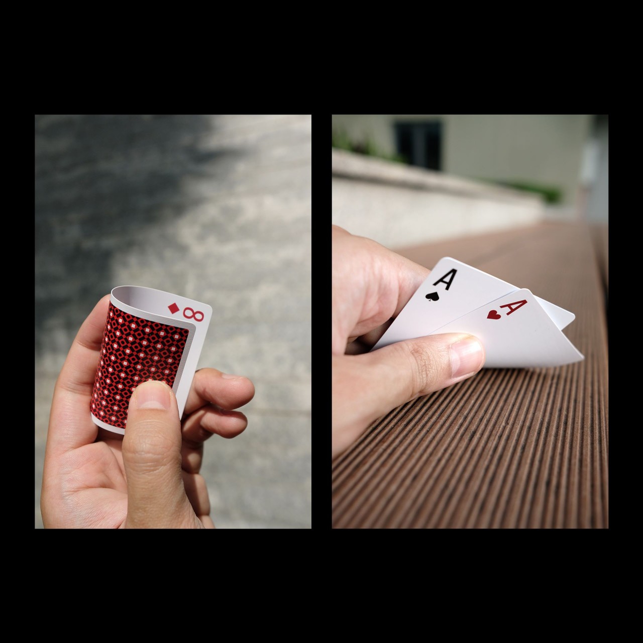

trying to get a shader up and running for a card bend
is this possible in Shadergraph?
2d unlit sprite shader to be precise
could someone write up, how I can get started? any particular video series that deals with vertex displacement i can follow to get a more clear picture on how I can achieve this?
Hello. Reflection Probe and SSR, which causes more performance overhead?
In low resolution. I just want to reflect the scene when it's rainy.
SSR if the probes are static
Probes if they're realtime, I expect
Ok, thanks.
To do palette swap, I would greatly suggest to use some "old school" paletting method :
Store the index of the palette in the sprite as color value, and use it to sample the palette texture.
Or, maybe it would be simpler to apply a tint effect to the skin parts of the sprite ? :
Have the exposed skin as greyscale pixels, and with an additional mask texture (or some shader logic based on the color value), multiply those greyscale pixels with a skin color tint (or use any blending option you prefer)
Hi all,
So, I'm playing with making my own Terrain Shader based on Height, that will be applied to multiple terrains over multiple scenes. It's pretty simple at the moment (only the Albedo in there at the moment, using temp textures), but it's working.
The only thing I don't like is the obvious 'banding'. Is there a way to sort of 'roughen up' the edges of each of the layers a bit? (all the gameplay will take place inside the crater(s).


You can add some noise to the height value
@karmic hatch I have tried that, but the edges were really hard and couldn't figured out how to soften them 😕
hello guys. is there a way to take parts of the scene color node and avrage out the colors to turn it solod in shader graph?


Hello. I have a big problem here. I made a shader for a fake shadow of an object. I'm showing the problem on the squares. Each square consists of two sprite renderers, one for the object itself and one for its child shadow.
When the objects are batched the shadow gets an offset regardless of the position of the object, the shadow looks good.
When objects are not batched, the offset is added for some reason depending on the rotation of the object.
I need the shadow to always look like the objects that are batched.
Please help me how to fix the shader and fix it. I do not understand how to do it.

My Shader
Shader "Unlit/ShadowStencil2DShader2"
{
    Properties
    {
        _MainTex ("Texture", 2D) = "white" {}
        _ShadowColor("ShadowColor",Color) = (0,0,0,1)
        _Offset("Offset", Vector) = (0.125,-0.125,0,0)
    }
    SubShader
    {
        Tags
        {
            "Queue"="Transparent"
            "IgnoreProjector"="true"
            "RenderType"="Transparent"
            "PreviewType"="Plane"
            "CanUseSpriteAtlas"="True"
        }
        ZWrite Off Blend SrcAlpha OneMinusSrcAlpha Cull Back
        LOD 100
        Pass
        {
            Stencil {
                Ref 0
                Comp Equal
                Pass IncrSat
                Fail IncrSat
            }


            CGPROGRAM
            #pragma vertex vert
            #pragma fragment frag
            #include "UnityCG.cginc"

            struct appdata
            {
                float4 vertex : POSITION;
                float2 uv : TEXCOORD0;
            };

            struct v2f
            {
                float2 uv : TEXCOORD0;
                float4 vertex : SV_POSITION;
            };

            sampler2D _MainTex;
            float4 _MainTex_ST;
            fixed4 _ShadowColor;
            float4 _Offset;

            v2f vert (appdata v)
            {
                v2f o;

                v.vertex = v.vertex + _Offset;
                o.vertex = UnityObjectToClipPos(v.vertex);

                o.uv = TRANSFORM_TEX(v.uv, _MainTex);
                return o;
            }

            fixed4 frag (v2f i) : SV_Target
            {
                fixed4 col = _ShadowColor * tex2D(_MainTex, i.uv).a;
                clip( col.a - 0.01);
                return col;
            }
            ENDCG
        }
    }
}
You need to change it so your offset happens in world space, not object.
Should be something like this in the vert function -
float3 worldPos = mul(unity_ObjectToWorld, v.vertex).xyz;
o.vertex = UnityWorldToClipPos(worldPos + _Offset);
Wow its works now. Thank you.
Can take multiple offsets & samples of the Scene Color, and average by adding them together and divide by the number of samples (though converting to linear space first (or perhaps HSV / another colour space) and back again at the end might be more correct)
Given it's multiple samples, doing it in a loop inside a Custom Function might be easier than node form.
If you do this on each pixel, the result will be more like a blurred image than these random spots of colour though. If you need that, what Spazi mentioned here makes sense #archived-shaders message - though I'd call it more of a UV-lookup than a refraction.
Might be difficult to do this on a 2D sprite as it needs enough vertices to actually be able to bend. Using a premade card mesh and MeshRenderers would make more sense.
"shader graph world bending / curvature" style tutorials might give you something similar, or at least a place to start for learning about vertex displacement
ty 🙂 will look into vertex displacement videos
Does SSPR has better performance than SSR?
hi,
if float4 color1 looks like this

and foat4 color2 look like that

how do i subtract color2 from color1 ?
So I have a shader which uses the scenes depth node, and it works in the scene view, but not in the game view? (In game view it flickers working if I click the mouse? 🤷♀️
Do you definitely have the Depth Texture enabled in your URP settings?
What's SSPR?
Yes, before I did that it wouldn’t work at all. Now that I’ve checked it, it works in scene view but not game view
I'm pretty sure it is a prepass. Where do you see it stated otherwise?
so unity still doesn't use MRT at all?
Not for forward rendering. Even in deferred, the depth buffer is not part of the MRT, it's just the depth buffer.
Thank you, I got it working with using a different material on the top faces
does anyone knows how so subtract two shapes from eachother using shaders? like this one
thanks moving the discussion to URP channel
it appears I was remembering correctly. There are condition under which depth prepass won;'t be needed even with SSAO requiring depth normal
ok no it was set to depth
depthNormal needs it
I find still weird they don't resort to MRT but I must miss something
So is this expected for motion vectors?
This image is me reprojection using the unity motion vectors the normals from the previous frame and displaying them here
The car is fast moving, and the camera is attatched to the car, with a floor underneath
https://pbs.twimg.com/media/F7F-T5PbcAAQouE?format=png&name=small

is it hard to make a fragment shader double sided ?
Hello guys
I have a fog shader with orthographic camera. I render the fog on a plane but fog looks slightly tilted from near to far

What could be causing to that? I'm sure the plane is not rotated
Hey so I discovered this game recently and I'm really enamored with the combination of 3D geometry with 2D sprites. It seems that the sprites are billboarded so they're always tilted towards the camera, but I'm kind of confused as to how sorting is handled.
https://www.youtube.com/watch?v=OG_lFaqnCoA&ab_channel=IDreamofIndieGames

Is Relic Hunters Legend a must-play game for all the fans of looter-shooter games out there? Find out what Ole Gamer Joe thinks of the gameplay, in-depth customization, and thrilling multiplayer experience. While the game offers endless hours of fun and excitement are they hours well spent? Grab your gear, assemble your team, and embark on a j...
If the sprites are billboarded then I assume they tilt backwards, and if they approach walls too closely, won't they clip into them?
Sort like this:


I guess you could make the bounding box of the characters big enough where this doesn't happen, but in this game they seem to get pretty close to the wall without issue.

I also think the characters are always drawn on top while against the wall on the side? Not sure on that one.

So my question is, how do you handle this sorting, especially considering the characters are clearly built with multiple sprites? Do they have some shader that defines sorting at the very bottom of the character?
That's Screen Space Planar Reflection. I suppose it performs better as it avoids ray marching in SSR.
But it seems that it only works fine on flat planes like water surface. I don't know if it will work well if the surface has normal mapping applied.
Unity has SSR and planar reflections, planar being more expensive since it renders from another camera
So if SSPR avoids using another camera and is restricted to a flat plane, I'd expect it to be cheapest of them all
Ok, thanks
Maybe I'm dumb, but I don't see how a screen space reflection, even if "planar" would work without raymarching 🤔
bgolus has probably the best method i've seen
Unity Forum
Hey guys, I've been experimenting with building a tactics engine using 3D geometry but 2D character sprites, similar to the Final Fantasy Tactics and...
I've actually seen this one, though I am concerned about the whole batching issue. Does that mean using this on many, MANY sprites is a bad idea? I would prefer being able to use this on foliage.
yeah
Ok, I've read a bit about it and I get it.
Now, it mostly only works for a dang glat mirror water surface, if you add ripples you'll have to fake it I guess by offseting the sample.
Maybe in the case where you only need planar reflections it is worth it, but I'm not sure it has a use if you already have SSR, the added cost might cut the gains.
it does break batching
I've used it in some smaller projects with a lot of enemies and it handled alright considered I had a lot of extra going into my pathfinding
How detrimental is this? Cause at a baseline I expect 150ish entities on screen using it.
And that's not including foliage.
It's something for you to gauge honestly, but it's not that detrimental unless you're doing this via mobile
I actually should try a webgl build and test it haha
I decided to use SSR now. Because I just knew an algorithm called Hierarchical Z-Buffer. It can significantly boost up the process of ray marching. I'm now reading this article (it's not in English) https://zhuanlan.zhihu.com/p/650035462 and the author implements that algorithm.

知乎专栏
Unity版本:2022 URP版本:14.0 基础SSR很简单,更重要的是如何对其进行优化和应用。在本文中,首先完成了在视空间的SSR,然后优化到屏幕光栅空间SSR,最后加上二分和Dither。 最后更新了一下HiZ,这是优化最大的…
about 4 times faster than normal raymarching
Is there any way to get back batching? Exactly what am I losing out on here? I am a bit unfamiliar with it, though I assume the idea is that repeated textures just get reused instead of being calculated for each instance.
Unless there's some updated fix somewhere, I've only really used the base code and implemented shadows
One thing you can test is the performance of billboarding via cpu vs this shader
Well it's really the sorting part that matters to me.
Well wait I assume you mean "billboarding via the cpu" to mean... rotating the sprite in actual 3D space.
Yeah, using lookat methods
cause that's usually the implementations I've seen otherwise haha
Well with this game, #archived-shaders message the sprites aren't truly billboarded. They are rotated to align with the viewing angle that the camera normally sits at, but when the camera moves or changes perspective, they don't change with it.
ya same but it's the clipping into 3D geometry that's the issue
phyiscally rotating it back results in that
It seems like they lock the camera which actually does give more freedom for giving a camera angle
I mean I've seen this set up of 2D characters, 3D world quite a few times now. There must be some standard that doesn't like... blast the shit out of the GPU 😛
Well, if you don't allow your player to move the camera, you can always draw your characters a little skewed
or the terrain
as you probably seen from that post with that legend of zelda game
I assume this is in unity because it looks like they read the article directly on rendering objects behind walls from unity's site
I have ya. There's this other game here
https://www.youtube.com/watch?v=u_8AR9TYjdM&ab_channel=NintendoofAmerica
Which is also 3D (though less obvious) which skews everything.

Wake and Kirby have come such a long way, and soon you'll be able to grab The Wild at Heart for Nintendo Switch. Coming Nov. 16, 2021.
Subscribe for more Nintendo fun! https://goo.gl/HYYsot
#TheWildAtHeart #NintendoSwitch
Visit Nintendo.com for all the latest! http://www.nintendo.com/
Like Nintendo on Facebook: http://www.facebook.com/Ni...
Characters are rotated back 45 degrees.
And the forward faces of hills are also tilted back
Sort of like this from a side view

Lot of ways you can do it. The clipping only becomes a bigger problem when you can rotate the 3D world usually
Ya. In my case I definitely won't be rotating the camera around. Strictly top down angle. Maybe a little jostling from a camera shake but that's it.
I just don't know if I want to commit to the whole... everything rotated thing.
Seems a bit easier to just solve this sorting issue and have a proper 3D world?
But idk
There's also rendering via depth, which I've seen some examples around, but it's quite a lot of work
^ for 3D rotation
what would that entail?
In my head at least it seems like what would make the most sense is to have the bottom of the sprite define the depth of the whole sprite.
I'm pretty sure those things are just quads under the hood anyway.
Just rendering everything on top using exact depth coordinates. It's a little screwy but I could see that working for a locked camera scene as well.
oh that does seem rough
I learned about the skewed level geomtry for The Wild at Heart by contacting the devs directly.
Might try that for Relic Hunter and see what they did.
hey i have strange issue with shader (azure vegetation) for tree. When im moving strange light go through leafs. Its not LOD for sure, what can it be ? (Unity Urp)
Is it possible to make a non screen space outliner that behaves like blenders selection outline (can see thru objects)
Currently using https://github.com/Arvtesh/UnityFx.Outline which works exactly as mentioned except the performance - multiple users all complaining about becoming a slide show when selecting multitude of objects

GitHub
Screen-space outlines for Unity3d. Contribute to Arvtesh/UnityFx.Outline development by creating an account on GitHub.
2023.3.0a7
Shadergraph: Added a new sample content pack that can be installed via the Package Manager. The samples contain descriptions, examples, and break-downs for a majority of the nodes in Shader Graph - helping users understand the inner workings of the nodes and see examples of how they work and how they can be used.
Shadergraph: Added a zoom step size option in the user preferences.
Shadergraph: Added dozens of new shortcuts for adding new nodes, toggling sub-window visibility, and moved several existing shortcuts to the shortcut manager.
Hi I've created a copy of unities "HDRP/Lit" because I want to add 2 int properties to the material "MatID" and "VariantID" but I don't know how to make them visible in the inspector?
Shader "Moonlit/Paintable"
{
    Properties
    {
        MatID("MatID", Int) = 0
        VariantID("VariantID", Int) = 0

[MainColor] _BaseColor("BaseColor", Color) = (1,1,1,1)```For the time being I guess I can just use debug mode to access them
If anyone knows though... It'd be nice if I can move this

Into this

If you notice at the very bottom of the Lit.shader there is “CustomEditor "Rendering.HighDefinition.LitGUI"
So you want to make a custom version of that as well
Oh I see, thank you 🙂 I should be able to figure that out
I appreciate it
Does anyone know how to make a shader that's invisible to the player but occludes other meshes?
Hi again all, so almost got my Terrain shader built, but I am now running into this error.
"Shader error in 'Shader Graphs/Master': maximum ps_5_0 sampler register index (16) exceeded at line 5125 (on d3d11)"
After some poking around, I understand why it's happening (limit on texture samples), but I can't seem to find a way to fix it. The shader is quite complicated (bunch of subgraphs etc. to get rid of tiling and whatnot).
Would anyone have any ideas on how this can be fixed? 😕 The shader has 8 layers, each containing 3 textures (Albedo/Normal/MaskMap).
I'm including a screengrab of the 'root' shader. (NormalMap not yet applied.)
Thanks.

why does a material's tiling value offset the texture?
Just to follow up on this, I contacted the devs and they actually shared with me how they did it.

The sprites are simply stretched along the Y, and the tilted perspective of the camera "shrinks" them back down to the intended size.
The camera is also quite far from the level with a small FOV.
So no fancy shaders.
I actually tried some warping with sprites but never was able to get the look just right
I think I've tried most non-shader methods and that's when I kinda delved more into shaders
I think the far Camera distance/low FOV is the key. Otherwise you're going to see quite a bit of distortion.
Head for example will be bigger since it's closer to the camera than the feet.
but also I was doing some full 3D camera rotation so the clipping was rampant. But if this method works for you, they're still widely used today
Ya for an anchored perspective, this works well.
erases a lot of headache too if you're doing realtime shadows and stuff like that too haha
Disable writing to the color/alpha channels, but write to the depth channel.
https://docs.unity3d.com/Manual/SL-ColorMask.html
The docs read backwards to me....IIRC using
ColorMask 0
DISables writing to the color+alpha channels. Using "ColorMask RGBA" would enable all of them (the default). But test it out, maybe I'm mis-remembering.
Anyway, if you update the depth buffer, it will occlude opaque objects that are deeper than the object you want to not-draw. Note that you'd have to use a lower queue or layer and draw the occluder first.
Note this would probably occlude transparent things too, and I'd assume if you're occluding opaques you'd also occlude transparents.
The tiling doesn't. The offset does, but it's a Tiling AND Offset note/function.
It multiplies (or divides?) by the tiling values, and then adds the offset values. The XY values are the tiling, the ZW values are the offset. The TRANSFORM_TEX macro does the calcs for you, and can be found in the include files depending on your pipeline. For example in one of the files listed in Core.hlsl
@meager pelican well I was just changing the value on the material inspector and it's 100 % offsetting not just scaling

When I scale the mesh I'm adjusting the tiling value on x axis
It's offsetting
Shader graph? Or code?
Neither the material inspector
It's default urp material for lit
Makes no sense to me
From my understanding if I local scale on y from 1 to 0.5
Then tiling needs to scale from 1 to 0.5 aswell
On the u axis in my case
OK, so it's mapping the whole tiling (0 to 1 for the entire "sprite sheet") to a value that is in the range of 0 to N where N is the result of the multiplication.
#define TRANSFORM_TEX(tex,name) (tex.xy * name##_ST.xy + name##_ST.zw)
From Cyan's link here: https://www.cyanilux.com/tutorials/urp-shader-code/
So it's multiplying.
It's just that you need to do it in discrete values of the proper size and it will work.
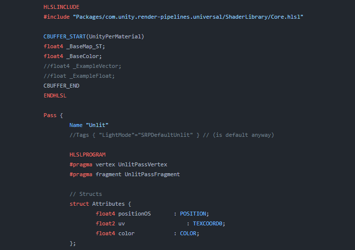
Explains how shader code (ShaderLab & HLSL) is written to support the Universal RP
so If it's 5 squares high and 4 wide, you'd use those values or their reciprocal. I don't remember if the inspect converts these values to the reciprocal for you or not. Maybe it's just using them, too early to do the math in my head.
Make sure wrap is on for sampling the texture too.
To prove it to yourself, don't change the tiling, and just change the offset in the inspector. And note the difference. The rest is just how the math works out.
It's just that if you're using fractional values you're shifting the "imaginary cutout" by small increments and to you it is looking like offsets, but it's not offset, its that your values are wrong.
@meager pelican but if my object spans 1m and it's uv goes 0 to 1. Then I squash the object to say 0.25m so the uv needs to scaled by uv.x*0.25 right? Which is what tiling does no?
That's what tiling DOES, butIIRC the values you plug into the inspect are going to be 4 and 4 for x and y. (and the reciprocal of 4 is 0.25).
Even if I put the reciprocal it shouldn't shift right? The uv at uv.x = 0 is still 0 even if I tile by 4 or 0.25 so it shouldn't be shifting only stretching / squashing
Right, but it depends on what the INTERFACE wants for input, and what it converts it to.
I couldn't tell the dims of your texture very well from the post. It's 4 wide and how high?...in squares.
Not sure what dims is
dimensions
It's 1m wide and 1m tall default
no....how many squares tall and how many squares wide (the squares in the checkerboard pattern)
Oh 4 by 4
OK, now we're talk'n. So plug 4 and 4 into the inspector. Make offsets 0 and 0
To show 1 grid square?
Right. I'm showing you how it works.
Did you get the one square? Assuming yes, now plug in 0.25 and 0 for offsets.
From what I understand you can't fix it, unless potentially you use texture arrays to reuse the sampler
The default Terrain shader uses multiple passes to get around sampler limitations, but those are not available to us with shader graph
Yeah that's what I've figured from what I've read. I've just cut down the amount of layers from 8 to 4. 😦 Kinda looks like ass, but meh. lol.
Should be able to connect Sampler State nodes to the SS port. It should be the same as using a "inline sampler" in code, avoids using the ones defined by the textures
I read a couple of things suggesting Sampler State but tbh, never even heard of it. lol. Will give it a go at some point, moved on for now cause it was annoying me. lol.
how can i use custom bits in shader for an effect?
something like depth alpha value
that isnt normally used
Like stencil bits?
yeah i think thats it
thanks
i didnt know its name
@meager pelicanare you still here
i had to pop out earlier when dealing with uv issue suddenly
im still having the weird offset issue
so i scaled the verts down so the mesh is half the height yet when i adjust the tiling it doesn't match


if it correctly repeated it wouldnt have the same colour tiles
doesn't make any sense to me
The sizes of the tiles is correct though. It's likely just that the model UVs isn't the full 0-1 range, but some smaller portion
hm well it doesn't span all to 1 because some space has been reserved for the sides of the model
but then i dont understand how people proc gen and keep their uvs correct
what would be the solution to keep the texture working correctly
If it's procedurally generated you'd probably apply specific UV values to the vertices rather than adjusting tiling
that would be even more challenging to convert vertex positions to the uv position 🤔
You can also do stuff like triplanar, which projects 3 textures from each axis using the vertex positions and blends based on normal vector. But that's more expensive than a single sample.
maybe i can just remove vertices beyond a certain distance so i dont have to scale it to fit the full length
or rather. remove the triangles
oh actually that probably wont work either
Probably depends what you're trying to do.
A lot of procgen stuff I've done deals with pre-modelled tilesets. With that the models aren't usually scaled - if I wanted one wall shorter than another similar to this, they'd be two separate models uv mapped differently.
yeh mines premade but the line could be any length so if it was 10.67m the .67m part is whats giving me issue
since i have to squish the last piece down to fit it
Is it only one axis that'll stretch like this?
yeh
Maybe if the front & back faces take up the bottom part of the UV map (full 0 to 1), it should be fine to scale/tile along that axis.
The model sides could be put in the top half of the UV somewhere, or maybe they can overlap some of the other faces if you don't mind it repeating.
i dunno why but the offset seems to be 0.44 on x axis:

but this seems like an arbitrary number at the moment so i can't code it in
the uv map looks like this

the margin at the top is for the top faces
I'd make sure that the vertex at the pivot of the mesh (bottom left?) is actually at (0,0) (bottom left) in the UV map.
Also if those are the UVs isn't it the Y axis being tiled above? Getting a little confused
yeah but for some reason its the x axis i have to adjust to get it right i have no idea why
@regal stagi fixed it

you were right to suspect it was odd that i had to change the x axis not y
so i re-unwrapped
and now it seems to work so the uv's must have been a bit off some how
https://pastebin.com/m5s5Ddf5
Hello, anyone know why my SSR keeps flickering as I move my camera?
Pastebin
Pastebin.com is the number one paste tool since 2002. Pastebin is a website where you can store text online for a set period of time.
If the shader works correctly, the second half of the video should not flicker with white points but pure black
I just set up a scroll with a mask and a scrollbar and everything works fine, except only the UI elements hide behind the mask and the game objects dont. How can I fix that? #💻┃code-beginner message
"A shader. Ask in shaders." LOL. Well, you came to the right place I guess. But it's hard to explain if you don't know shaders, particularly since the thing you want to do will probably require hand-coded shaders.
There's one discussion here: https://forum.unity.com/threads/render-ui-on-the-top-of-everything.1402822/
The idea of using a second camera for the UI stuff (separated into a UI layer) might solve your problem without custom shaders. Then there's the "overlay canvas" concept.
Lastly there's the custom shader concept.
What pipeline are you using? Are you in VR? What target platforms do you want to support and can you "take the hit" of drawing the non-UI elements that will eventually be occluded?
Unity Forum
Hello everyone,
In VR, sometimes when opening up the UI, it is blocked by the objects in the scene. I wonder if there is any solution out there using...
Not VR, it's just 2D
It's just a simple 2D scrollbar
What pipeline? BiRP (Older built-in render pipeline), URP, HDRP?
I dont really know what you mean, propably the one which is standard
Where can I find pipelines?
Nothing is simple in shaders. 😉
But it's fun and you learn a lot and its worth doing!
Pipelines? In the docs: https://docs.unity3d.com/2023.3/Documentation/Manual/render-pipelines.html
You can try the 2nd camera trick for an easy-out. The problem with that is that you MAY have to render all the stuff behind the scroll, unless you render the scroll first AND you can find a way to tell the scene objects to ignore those pixels (like perhaps a stencil) but in that case it may require hand-coding the shader.
@astral bobcat
I'll take a closer look, ty, expected that to be a 30 sec fix...
I don't do much 2D so maybe someone else will chime in.
You've obviously played with the thresholds and other settings? That didn't solve it?
The "2nd half" of the video added a large blob shadow? What's with that, what's the change between the first and 2nd half?
Or is that a reflection?
Some ray will hit the model while ray marching, but some will not. So, in the second half video, I set the pixels whose ray hits nothing to black instead of the original color. I had played around the settings. I also saw some one on unity forum said that "the low thickness will make the plane flickering". But in my case, no matter how the thickness is, the plane flickers.
Well, that's ray-marching/tracing for you.
One thing that's often done is to render to a render texture at lower resolution, maybe blur, and then upscale the result in a blit/combine pass.
Screen space reflections are common and have limitations, although they shouldn't be doing what you're showing, so it's a fix needed for sure. The easy way is to use a cube mapped reflection and avoid the whole overhead of rays if you can. 2 cents. But maybe you can't do that.
But my scene is dynamic and reflection probe will cause extreme performance overhead. Is there any way to solve my problem? I had seen many SSR tutorials but none of them mentioned this problem.
The reflection probes DO cause overhead, sure. But so does SSR. Depends on the resolutions you use, your needs, and benchmarks both ways. One solution is the 1st half's method, the right number of rays and thresholds, and a blur pass in your command buffer. But without playing with it all, IDK what else the problem is. If there's something besides settings, maybe someone else will spot it.
I had tried realtime reflection probe with the lowest resolution. It still costs more than SSR. I don't know if you have heard Hierarchy Z-Buffer. It's an algo that can boost up raymarching 3-4 times faster. So I think the performance overhead would be ok (if I improve my shader in the future) . In the first half you might notice that at some angles, the reflection totally disappeared so blur does nothing. Anyway thanks for your help!
Did you also play with probe frame settings? You don't have to generate all 6 frames each time.
Anyway, you're welcome.
I'll look up Hierarchy Z-Buffer, maybe an acceleration structure of sorts?
Yeah, SSR has problems, and once you see them you can't un-see them. Yet they're real common, even in AAA games.
Did you also play with probe frame settings
Oh I didn't notice that. If that still costs too much, I'm gonna seek for a SSR implementation on github 🤣
Right on. I mean, you gotta check out all the options. There's a reason SSR is common, even if it is imperfect. All depends on use case.
Some games combine all reflection methods. Like Mirror's Edge: Catalyst or RDR 2.
Well, at least I don't remember RDR2 having SSR but it definitely had some kind of realtime reflection probe setup according to a frame breakdown I read.
Realtime reflection probes are relatively uncommon
Extra cameras required to render them are particularly expensive in nearly all modern engines it seems
And the amount of pixels you need for a sharp reflection is huge when you have 6 perspectives per probe
Here's an excerpt (well time link) from Acerola's intermediate water shader where's he's discussing skybox reflections on the water. Anyway, there's some things to think about, and it's an interesting video. He went to the trouble of talking about how sucky SSR is in terms of realism, but it's usually cheaper, depending on the resolution you want for your reflections.
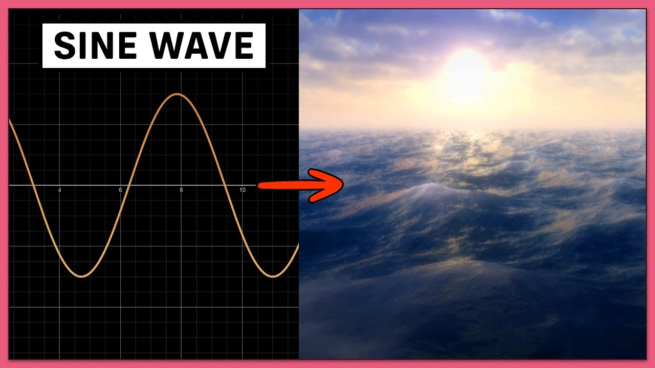
Get a free 30 day trial and 20% off an annual plan at
https://brilliant.org/acerola ! #ad
Many Acerola viewers ask the question: How do games render water? Well, real time water rendering might sound intimidating, but it turns out most video games (Final Fantasy XVI, Elden Ring, Genshin Impact, etc.) use a relatively simple technique. How conve...
how can i acces light probe data from shader graph ?

i dont want to use a lit shader, i want to "blur" it so the whole object still apears as flat but matches the environments brightness
i found this but i dont have a node like that

iirc the Baked GI node would handle it (but also sampling of lightmaps if the object is static and has one baked)
Otherwise can try a Custom Function node
thank you, that worked
can you halp me with something else ?
I need to take the average color/value of the light probes since i want my models to look flat(like theyre 2d)
how would i do that ?
my current solution looks like this but its not the best i think

it only works for non static objects

someone had showed me how to do this about a month ago but it appears upside down can someone help teach me how to make it not upside down?


Try Negate on the view direction - or maybe Multiply by (1, -1, 1) if you just want to flip the Y axis.
Alr ima try that rq
Static objects probably are lightmapped, so would be sampling lightmaps instead of probes. If you only want probe data, might need to use that SampleSH(Normal); in a custom function node.
how do i do that
i dont know anything about shaders im sorry
can i still use the same material for that that automatically chooses between the two ?
The graph you showed has a View Direction node going into the Sample Cubemap. Add a Negate node inbetween those.
it worked thank you
In shader graph, I have a shader that I am using to paint cars based on an input color. I am multiplying the base texture by an input color, and this works correctly. How can I mask the area that is multiplied so I don't paint certain areas? In this case, I don't want to apply color to the car's glass. I have a mask texture2D (alpha) but I am not sure how to set up the nodes to get this to work.

You'd usually use the mask (I assume output of the bottom texture sample) as the T input of a Lerp node.
Can then set A to the tinted result (output of Multiply), and B to the untinted result (RGBA from Sample Texture 2D of Base Texture)
Or alternatively lerp between white and your Paint Color and Multiply with that. Either works.
Side note, you can also group nodes by highlighting a selection, right-click and select "group selection". Using sticky notes makes it pretty hard to read the nodes and see connections.
Thanks! I don't think I'm doing it right. I'm not quite sure I follow your explanation of input and output.

OH I didn't have to invert the alpha. That did it!
Thanks!
Hey guys, I have a question about shaders. So In 2D I want some fake shadows that connect with other shadows. Currently we use a second camera to render to texture the whole scene except for the fake shadow sprite, and add some color to it via shader graph (this is important to have some aesthetic quality to it).
2dLights don't affect this layer.
Anyway, having another camera cuts our fps by 10 frames, and I'd love to know if there is a way of achieving a similar effect or same if possible in a more efficient way?
So I made this map in blender and I'm just wondering how I would get this color gradient effect across multiple objects in unity

Maybe use world position as uv to sample a gradient map? or use a function to describe it. btw your map looks nice
In this video by Sebastian Lague, he sets up the scene to use a custom rendering system. Do you know how I would go about implementing that?https://www.youtube.com/watch?v=Qz0KTGYJtUk

I tried creating a custom ray/path tracing renderer. Featuring: maths, shaders, and cats!
This project was written in C# and HLSL, and uses the Unity game engine.
Source Code: https://github.com/SebLague/Ray-Tracing
Support the channel: https://www.patreon.com/SebastianLague
Coding Adventures Playlist: https://youtube.com/playlist?list=PLFt_AvW...
Hi, how can I prevent the grass grow out of the platform?

My favorite part of shader creation is finding neat little things like this, it seems to invert whatever's behind it when Alpha Edge is very close to zero.


not an issue or anything but i think it's kinda neat
I think I'm happy with how this looks so far, probably gonna go to bed for now and work on it some more in the morning

Hi! In unity docs about writing shaders for different graphics API (https://docs.unity3d.com/Manual/SL-PlatformDifferences.html) there is an advice to use float4 and float4x4 while writing into StructurredBuffer because float4 has the same size on each graphics API, and doing so may help to avoid wrong data writing in buffers. So if I have for example 3 float values it is better to pack them into one float4 value with empty one float. How then should I implement int? Does int4 has same sizes across different APIs? Or should I use float4 and round it to use as int ?
Probably because the alpha is leaving the (0-1) range it's usually supposed to be in. If it goes >1, the background gets inverted, and if it goes <0, you have your transparent material inverted and your background brightened.
Final color = (1-alpha)*background + alpha*foreground
(for alpha blending)
How to make such a shader? https://assetstore.unity.com/packages/vfx/shaders/uv-independent-gradient-249703

Add depth to your next project with UV Independent Gradient from fisekoo. Find this & more VFX Shaders on the Unity Asset Store.
I wonder how to achieve this?
Hey. I'm noob in shaders. How can I don't render transparent material if it's behind same material like glass blocks in minecraft?

Perhaps with a depth-prepass with ZTest On, but Minecraft does render transparent surfaces behind others - if you have another layer of glass separated with an air block, you can still see it.
But the faces between blocks do not exist as it likely generates a combined mesh of only visible faces, rather than using cubes.
So it's more of a procedural mesh generation question - or manual editing of mesh, if it's just imported and doesn't need to actually update with block placement.
Assuming the objects aren't statically batched, can use one of the axis of the vertex positions to lerp between two colours (e.g. lerp(colorA, colorB, pos.y);.
If that position is in object space, it would rotate with the object. World space, it would be relative to the world, but you'd want to remap to still follow the position of the mesh. In ShaderGraph, can do that by subtracting the Position from the Object node from the Position node set to World. (Or Remap that using the World Bounds, assuming 2022+)
That's the general idea anyway, should be a place to start.
Exactly, I needed to combine the mesh, thank you!
I'm thinking of buying a book to learn shaders in its code form. I just want to make sure I'm learning the correct language. Is it correct that Unity's built-in and URP use the HLSL language?
Yep, HLSL is your go to 🙂
Well, built-in is mostly CG, but the syntaxes are like 95% the same
Do you think I should purchase a book relating to only CG also? Sorry for the late response
No, I think you're totally fine with HLSL
That's cool - thank you very much
Hey everyone, I've got a problem I can't wrap my head around:
So, I'm using HDRP, and I want my game to have that curvy vibe like Animal Crossing, and I nailed it with the Curved Worlds Asset.
Now, here's the snag: my game rocks this clay look with a different shader, and if I slap on the curvature shader, well, obviously, I lose that clay vibe. I have no clue how to blend these two shaders into one.
The clay shader is made in Shader Graph, and the curvature shader is pure code.
Can anyone lend me a hand? Ask me whatever you need, thanks a bunch!!
With curvature:
Real graphics game:
In this video by Sebastian Lague, he sets up the scene to use a custom rendering system. Do you know how I would go about implementing that?https://www.youtube.com/watch?v=Qz0KTGYJtUk
I tried creating a custom ray/path tracing renderer. Featuring: maths, shaders, and cats!
This project was written in C# and HLSL, and uses the Unity game engine.
Source Code: https://github.com/SebLague/Ray-Tracing
Support the channel: https://www.patreon.com/SebastianLague
Coding Adventures Playlist: https://youtube.com/playlist?list=PLFt_AvW...
Can someone help me debug my HDRP shadergraph?
I'm essentially trying to recreate this effect in the Original image with these conditions:
Given normal map
Given height map
Pixel displacement mode
Currently my shader graph properties:
Input: wood texture
Input: height map texture
Generate a normal map given the height map texture
Create a height map effect via the Parallax Occlusion Mapping node...
I am confused what I am doing wrong since the effects are slightly different - it doesn't seem like my height map is working correctly?


can the object: scale node not be trusted? The material looks tiled correctly before pressing play. But, on play, its like it uses a completely different scale. I've added a modifier, so, at runtime, I can find the right modifier, and then it looks fine at runtime (but no longer looks good when not at runtime).

The Object node data is calculated from the model matrix. But that might change when entering play mode if multiple objects are batched (specifically static or dynamic batching where meshes combined together into one, SRP batching is fine)
The video should show this. It uses OnRenderImage to blit a fullscreen quad to the screen (though that only works in Built-in RP)
Ok, maybe I just misunderstood what was happening. Thanks.
Recreate the curvature calculations and connect to the Position port in the Vertex stage of the clay shader graph.
Should also be able to find tutorials for world curvature that use shader graph - though I think these are usually written with URP in mind. Still could be useful. HDRP doesn't support the camera node iirc... but should just be able to use "World" space and ignore subtracting the camera position, as that space is already camera-relative in that pipeline.
Hey, I’m trying to make a mobile car shader that’s on par with some of the typical car games like car parking multiplayer. My current thought is do all the gradient, specular, etc in the vertex shader. Then use a Cubemap inside the fragment shader. Is this a decent approach?
Hi, guys. I have to hide anything behind a plane except several particular objects.
I'm a newbie for shader. I know somewhat about depth-mask and stencil mask. However, since I'm making mods for a game, I cannot change the shaders or render queues of this sort of "anything" in the game. What I can do is just manipulating my "particular objects" which I want to prevent from hiding. Their render queues could distribute from 1000 to 3000, and my "particular objects" are greater than 2500 and cannot be lowered.
Is it possible to achieve this effect by using shaders? Really appreciate it if there is any clue. 
Hello! I'm trying to use shader graph to capture the distance of a surface from the camera in the Z direction for use as a mask for displaying sharp details on faces that are close to the player. I've posted screenshots of my best results so far, but you can clearly see that it isn't cleanly highlighting the near surface to the player as one might expect. What I'm looking for is for the white part of the surface to appear more radial, as in a true measure of distance. Can anyone see where I'm going wrong?
Yes, that is a material zoo in the background.
Thanks so much if anyone reads.


I found a solution, but I'm not sure that I like it. I would prefer to use the view space if possible. Does anyone see a better way of achieving this?


Don't try to recreate the normal from the texture, use the pralax uvs to sample the normal map.
You can use the position node, in view space mode.
Then divide the z value by viewdirection.z
Thanks! I'm onto experimenting with that.
If you have a material read from the opaque texture, it won't see any transparent objects behind it
@drowsy abyss Are you familiar with "detail maps"? In case this wheel might not need reinventing
Yeah, but in this case I'm not using texture data, just isolating a channel for use later.
It took some experimenting, but here's a working solution! Thanks!


Not that it should matter much for the compiler, but you could split the view direction Z first, then negate the value (there is a negate node btw 🙂 )
Yeah, but between that and the remap, I was leaving my options open for hacking nodes together until something worked.
Does View Direction provide a vector from the camera for each fragment rendered? I thought it would have been the literal camera orientation.
OH it literally is when set to world space. I get it.
That would explain why the 3d preview looks so spherical. That is actually really handy to have.
what the name of the book you will buy,maybe if it unity bible shader we can buy it together?

Are you thinking hard copy or virtual? In terms of books, listing the best ones that fit my needs, so I don't have a definitive answer to the first question
😦
Well for hard copy I need to pay the shipping fee so I prefer e-book,I see if you found anything good please tell me
Lol yeah, if you have said hard copy, I was also wondering how sharing the book would have worked - we'd have to ship it everytime anyone one of us wanted it

Anyone know how to create a Skybox Shader where I can use alpha? I need it to do a transition from passtrough to Virutal reality with Skybox, in mixed reality i have to see the real world when i switch to virtual i want use an alpha field do animate a transition from real world to skybox
What was the name for the shadergraph plugin which did the named-reroutes thing again?
Are you referring to - https://github.com/Cyanilux/ShaderGraphVariables
YES - thank you
Wait a second 👀
That's your thing!!
Just wanna let you know this stuff is amazing ❤️
@amber saffron well in a later prototype the height map is going to be made dynamically ( someone will be drawing to a render texture that will passed in as a height map ) so I kind of need to have the normal map from texture
Then try to tweak the offset and strength values of the normal from texture node. This is probably the easiest to do here
You probably want the amplitude of the parallax and the strength of the normal from texture to be linked btw
Ok! let me try this - and thank you for responding 🙂
But otherwise @amber saffron - did I hook up the nodes correctly between the parallax occlusion mapping, the sample texture 2D, the normal from texture node and the master nodes?
Yep
Hmmm so I'm fiddlin w/ the amplitude of strength & parallax and I can't seem to get the wood texture's "softness" that the original has...(in the pic, the top is the shadergraph version, the bottom is the original material)
I tried to match the smoothness between the original material's properties and the shadergraph, turned off depth offset to match the original material's settings - is there another property that I'm missing?

The amplitude seems way to high
Hmm I set it to be 5 like in the original material 😵💫
And you should try to tweak it this way :
Amplitude param -> amplitude of parallax
Amplitude param * normal strength param -> strength of normal from texture
That way both a related together, but you can change the normal mutliplier
Also, this is somewhat unsure looking at the screenshot, but looks like the height is inverted between the two results 🤔
Like, one has the shaped carved, and the other embossed
Not fully sure of the terms :/
On the top the shape is "down" and in the bottom it is "up"
ya i see wat you mean
i can't tell if it's the focus of the camera and how the light hits it
let me address that after i add a normal strength parameter
Ok so I did the separated normal strength and amplitude and am fiddlign around - still the same effect?
Also I think the different inverted appearance gets resolved when you move the camera around?
I think you need ato have your "strength" value between 0 and 1, prob something like 0.2 : look how the normal is already very high contrast in the preview.
You could also expose and tweak the "offset" value of the normal from texture node
Ooo I see! Thank you let me try that
Where can one find information on the URP Sample Buffer node? I've been trying to make mine render out something which isn't just flat black, but idk how to change the node's output
This seems to be a nice explanation : https://forum.unity.com/threads/undocumented-node-in-shadergraph-for-urp-2022-2-what-does-it-do.1371792/
Okay, I didn't understand that (I found that post a while ago), I just need to know where in my C# can I do this:
Sample a global texture called "_BlitTexture",
I'm not super experienced with SRP
Note that the sample buffer node is mentioned here : https://docs.unity3d.com/Packages/com.unity.render-pipelines.universal@17.0/manual/post-processing/post-processing-custom-effect-low-code.html
For the 3 possible source buffers :
"BlitSource" is globally "what is on screen before this post process is rendered"
"NormalWorldSpace" probably needs to use the deferred renderer or an additional renderer pass to have an active normal buffer
"motion vectors" will also probably need to have motions vectore enabled somewhere, but idk where to enable it. Maybe TAA or motions blur needs to be active
I'm attempting to make a Skybox shader that uses the direction of the main directional light source to create a sun. I already have the light source direction, I'm just not sure how to make the graph know when and where to render the sun.
I don't want exact answers, preferably just which nodes I will be needing
As the skybox is not a mesh itself, you can't rely on any position information to render. But you can use the view direction. Use this with the light direciton and a dot node, and you should be able to draw the sun 🙂
Alright, I'll try that. Thanks!
that worked perfectly, thanks!
I use the metallic map in the screenshot. Applying it to the URP/Lit Shader. For some reason the metallic maps is rendering my blade black. Any idea why that is?


Shader math question
Distance through a cube is a simple formula to calculate
Is it possible to do distance through other shapes, such as a triangular prism just as easily?
Ideally without ray marching. I don't know much about geometry math so if its nontrivial to calculate distance through shapes other than a cube or sphere, I can live with that

pictured: distance through cube top left, various failed attempts to get distance through triangular prism
I figured since its just half a cube that it would be easy to describe in maths but no luck so far
hmm thinking about it in cube terms, maybe it would just magically work if I subtracted a cube from a cube on an angle?
Or am I just wildly out of line in my comprehension of how distance works

Should be able to calculate the distance to the plane that cuts the cube in half (look up ray-plane intersection), and take the minimum of that vs the distance through cube.
my attempt at SDF cube cutaway from second SDF cube didn't pan out so Ill look into as you suggest


almost sorta kinda worked on the meshs that are the shape of the SDF but still jank

okay ray-plane intersection time
Does the formula for a prism SDF help me in any way get distance through that volume?

Or do I still need to do advanced maths?
Yeah not making any progress
just a lot of strange distorted returns that look nothing like triangle prisms
time better spent elsewhere, going to give up on this because I'm not knowledgeable enough to solve it without handholding for the entire thing
it sucks being an artist who wants beautiful visuals when those visuals are entirely dependant on being a mathmetician
and I am not a mathmatician
is there a shader for blender objects out there? I exported all the textures from blender but some of the blender options arent in the unity standard shader
I don't think SDFs will help you get a distance through a shape. SDFs give you the distance to the nearest point on the surface of the shape, while I think you want the distance along the view vector.
For a convex shape, that's probably distance(entryPos, exitPos); and if the prism matches the mesh, entryPos should just be the interpolated vertex positions (Position node)
For calculating the exitPos you'd likely need ray-intersection maths. I imagine a mix between a ray-cube and ray-plane intersection, but that's where my maths knowledge breaks down.
Unity shaders are technically capable of almost everything that Blender shaders are and vice versa, but there are no tools that exist that could convert from one to the other
where would i put subsurface and stuff though?
HDRP supports SSS out of the box: https://docs.unity3d.com/Packages/com.unity.render-pipelines.high-definition@14.0/manual/Subsurface-Scattering.html
For BiRP and URP you need a custom shader
i followed a tutorial on switching to hdrp and now the scene is just blank

the object is there but not rendering
Check pinned messages in #archived-hdrp for upgrade instructions that are up to date
Note that render pipeline upgrade is not an easily reversible process so use version control or backups, as always
dw, deleting the asset reverts it