#archived-shaders
1 messages · Page 56 of 1
Show what you created. The texture doesn't matter, it will be overridden by the spriterenderer
so i select none in the sg material, i don't drag any texture to that field?
Flickering how?

it's vanishing and appearing again
(you just need to create MainTex properly like this)

Is your sprite just interesecting something else? Or at the exact same depth and sorting as something else?
actually
it's the animations
you need to fix your texture so it uses the right one that matches what's being animated
when it's swapping out the sprite the mesh is changing, which is clipping your character
but the shader is using the wrong texture
just tell me this. Do i need to drag a texture to the sg material like this?

No, you just need to use the correct name
sry the name of what?
^ the name of the exposed texture
change it here?

it was supposed to be MainTex without space ohh seriously fuck me!! I was wresting with this for hours for just a fucking space!! Sry man, sry for wasting your time
All good 👍
I think you may want to use a compute shader and a compute buffer
easy to get the data back to cpu that way
Hi guys, is it possible to keep the texture aligned with the direction of track?

This outline shouldn't have much of a practical effect on anything but you can get it to be "tight" if you enable alpha clipping
The default sprite shader might be using it, or it might be just a scene view effect
the tracks uvs should follow it
ok fixed it. I just entered the Main Tex with space, that was the whole problem
actually i want the texture to be align with object coordinated instead of uv
that's exactly what will happen if you make the uv's x component start at the left side of the track and the y component start at one of the ends of it. y should be 1 at the other end, and x should be 1 on the right
this is what i achieve with these nodes


how do I set a compute buffer for a texture? should I just send the texture without do any struct{}?
the UV of track patches are placed above on each other. so i dont know how can i use UV for this
you know that instead of rotating it you could just immediately get the object position instead of the world position, right?
in the dropdown


why do you specifically need it to be a texture? I think in a texture you can't really read back uints to cpu
play with the tiling


because I don't know how to send 8000 arrays of vector16 inside a struct to the gpu
my texture is 8096*16
will 8000 struct with inside 4*vector4 do the same job?
or a struct with inside 16 floats as an array
a compute buffer has some x, y, z sizes and element size
so you can just make a compute buffer that's 8096x16 Vector4s
ah that's 2D noise, swizzle the object coordinates differently
didn't you need uint?
you can read back float4s
from texture too
I thought you needed uints
swizzle means mix? and how i we achieve the effect you mentioned?
I decided to use uints for store thread id... I think it's better If I show you the code... it's uncomplete but should give you an idea of what is happening inside my shader
RWTexture2D<uint> _grid;

uint x = uint(abs((_dataBuffer[id.x].pos.z*64*64)+(_dataBuffer[id.x].pos.y * 64) + _dataBuffer[id.x].pos.x));
    float2 xy = float2(x, id.y);
    _grid[xy] = id.x;
swizzling is doing e.g. [float3].xzy or [float4].xxz or something. It's basically just picking out the components you want in the order you want and making them into a new floatn
there's a swizzle node in shader graph too
is there any tutorial on it? i am not sure how can i achieve this effect, but i try
There's a swizzle node in shadergraph; doing a.xzy is just the same as float3(a.x, a.z, a.y) just faster to write
ok
Why is this logic not creating parallax? Camera position is the camera's position, but the camera is in orthographic projection so there is no parallax, so I am trying to fake the parallax by offsetting the vertxes but for some reason, EVERY mesh is offset in the exact same direction, globally

which makes no sense to me since object position is different per mesh, there's no logical reason why they would all universally offset in the exact same direction
ithere something wrong with the object space position node perhaps?
because there othewrise I don't see how there can be anything wrong with my logic

the reason I can convinced something is wrong with the object position node is because the meshes do this weird insane flickering effect any time object position is sampled anywhere in the shader graph values
removal of object position fixes this
but I need object position because how else am I supposed to sample the object's position?
I DO NOT WANT vertex position because that will distort the meshes, parallax does not distort meshes, it offsets all vertexes uniformly
For the flickering, it could be because the objects are culled
How can I determine if they're being culled? Currently they're stock 2D sprites, with a stock unity camera set to orthographic, zero other parameters have been changed
The renderer bouding box is not affected by the vertex displacement, so you could end up with a mesh that visually should be visible, but where the renderer is offscreen
Find a way to display their bounding box, like temporary putting a box collider on the object
I'd prefer to do parallax with scripts to avoid dealing with bounds entirely
Since the effect is per mesh anyway rather than per vertex
I read that its way more performant to offset vertexes in shader than to loop through every single mesh every frame and do distance tests between the camera and the object for hundreds of objects, is that not the case?
It doesn't sound too bad if you're not finding new references to the meshes every frame
I don't think it requires a distance check either but I'm not sure
🤔 how can you do parallax without distance, isnt parallax completely dependant on distance?
Even with shaders you'd have to update the bounds somehow or stop them from culling
Sprites with the same material will also have batching which'll combine meshes so it may not be possible to extract the object positions
Oh right, sprite renderers
ooh THAT I did not know, that might be why they all offset universally as a single object
Unless you have a VERY big number of objects to update, reclaculating their position in a loop should be very fast

adding box collider highlights the weirdness better
some at randomly bellow, lots are randomly way above, none are where the mesh actually is 
since this doesnt occur if I dont use object position, like Cyan suggested the interference might be coming from the batching
If you need parallax in two dimensions only then it should be enough move the object a fraction of the camera's motion when the camera moves
Hmm and I suppose that if performance becomes an issue, I could always only parallax things you can actually see/potentially see instead of everything
Ill test the above with 3d planes instead of sprite renderers to see if the batching is the issue, and even if it is the case its sounding like I should just do this in script instead of shader
I have some sprite parallax scripts from years back that might be potentially useful
#🖼️┃2d-tools message
🫠 also another weirdness, the fewer non-sprite renderers in scene, the less it flickers
I just deleted all the non-sprite renderer meshes and the flicker reduces more and more as each was deleted, until there;'s no flicker when all scene meshes are spite renderers
I dont know how batching works but maybe that is another finger pointing at athat
tryin planes for the moment then checking those scrips
Maybe other renderers inbetween the sprites prevents them batching
Ah yep using quads instead of sprite renderers, it works 100%
but my enviro is 2D so I was going to use sprite renderers to make sorting easier, so going to look at Spazi's scripts now
Thanks for the help, Cyan, Spazi, Remy
good to know the logic was correct and it was sprite renderers batching causing most of the jank I was getting frustrated not being able to identify any mistakes in my shader that were causing it, its a relief to know I didnt make a mistake, it was unity
or rather, the mistake I made was not in shader, it was being a sprite renderer
So, I have this hlsl code, any idea why it returns 0?
//Inigo quilez https://www.shadertoy.com/view/XlXcW4
const uint k = 1103515245;  // GLIB C
float randValue(uint3 f){
    f = ((f>>8)^f.yzx)*k;
    f = ((f>>8)^f.yzx)*k;
    f = ((f>>8)^f.yzx)*k;
    return f*(1.0f/float(4294967295));
}
I just want to use this, in unity https://www.shadertoy.com/view/XlXcW4

Inside a shader
Maybe if you do the RG split after the subtract?
Either move the declaration of k inside the function or add static to the const uint k. HLSL defaults global variables as zero & only set externally.
It's still returning 0
Hi, I have this room model with simple square tiles textures... I wish to create an effect using Shader Graph that changes the color of some random tiles to a random color ... Any idea how I should go about?

what do you mean by "turn"?
Change the tiles color for instance... it doesn't matter.
it matters a lot
when you said "turn" I Imagined something like... rotating
which is very different from changing a color
oops... you are right 🙂 I meant to say turn on
Most recent Rider version brings many improvements to ShaderLab support 🥳
https://blog.jetbrains.com/dotnet/2023/07/25/improvements-to-unity-shader-files-in-rider-2023-2/

The JetBrains Blog
With the release of Rider 2023.2 just around the corner, it’s time to take a look at all the new features we’ve added for Unity shader files.
I would do the following:
- Multiply the UVs by the number of tiles you want
- Put this value into a fract node, and also into a floor node. (not sequentially, in parallel). The fract node gives you the in-tile coordinates, while the floor gives you the coordinates of the tile
- Put the output of the floor node into your favorite hash function that returns a value between 0 and 1, then put that into a step node where the edge is the fraction of tiles you want 'off'. This randomly selects tiles and returns 0 if they're off, 1 if they're on.
- Taking the output from the fract node in 2., do min(fract value, one minus fract value). Take the min of the x and y components. Divide by 2, and put into a step. The edge in the step node is the width of the line between the tiles. This should give 0 for the edge of the tile, and 1 for the inside.
- Put the output of the step from 3. into the T input of a lerp node; put the color of an off tile into the A node, and the color of an on tile into the B node. This returns the color of the tile; if it's on or off.
- Put the output of the lerp from 5. into the B input of another lerp; into the T input put the output of the step from 4., and into the A input put the color of the inter-tile lines. This adds the lines between tiles.
Wow... thanks @karmic hatch. Amazing!

Is someone capable of explaining to me what the hell could be happening here?????
I thought frame debugger was supposed to not change if i'm inspecting it??
How is that even possible?
Hi, I have a character and I wanted to try applying some gradient to them but theres an issue when they bend over, they change colors. Its a ragdoll so the player can easily fold in weird ways, this issue happens a lot cause of it.
I know the issue is because I use the position node, but is there an alternative? I tried UV but i dont think it works on my character because of the UV mapping. if i directly plug the UV node into my base color, its just all mostly green/dark green (which I believe means its all roughly the same value and wont work for a gradient). Using URP


Each time you refresh the frame debugger by selecting a new draw call, it needs to re-render the frame up to the draw call you selected. Instead of rerunning the same draw calls as before, it just re-renders all the cameras as if it were a new frame, while keeping the same game time. But all the camera render events are invoked again and such, so things can still change when you're selecting new draw calls.
Hello. I'm using the scifi pack from synty. Their planet rings are using a legacy shader. I'm trying to convert this to a standard urp shader. I created a new material to try to replicate it, but it doesn't seem to render. It only shows on the right-hand side because I have it selected. I'm not sure what I need to do here. Does any one have any advice?
By doesn't render do you mean it's completely invisible when applied to objects in editor?
Oops, I forgot to attach the screenshot. Sorry,

Might be a dumb question but is that particular particle shader usually supported by urp anyway?
The legacy one? It appears to be. Just seems odd to leave it on "legacy" but that's what I'll do if there's no click boom bam to migrate it
When the shader works with bitwise and shift operations keep values as bits, here is working one in shadergraph with custom function, I dont seem to find function to get current frame index in shadergraph so you either have to supply it from C# or multiply the Time value to some number above your target frameRate to see it change every frame.

How do I make a shader?
Hello! Sorry to bother everyone but I'm having trouble with my shader (written from scratch)
In unity 2021.3.24f1, I'm writing to a shader to create the effect where:
The user's silhouette (as roughly detected by the azure kinect depth threshold on the kinect's depth data) acts as a mask/cookie cutter and will reveal a video playing wherever hte user is. Otherwise there is a blank picture of the desert.
I'm using the Examples for the Kinect plugin and in the KinectManager, I am able to set the max depth distance to 3 and the correct depth shows (in the preview on the bottom right)
However, clearly the output is super wonky and I'd appreciate any help debugging these two lines that I think are the problem:
fixed4 maskedColor = lerp(_BackgroundColor, mainColor, zCheck);```

Here is my shaderIt'd be good to know what you're expecting to see
But honestly from your description if you're literally displaying the correct image down in the bottom right I can't imagine what's wrong
I'd try simplifying a little, displaying your main kinect image full screen as the mask for the video, it seems like one of your lines will have a slight mistake so just try narrow it down
I can't imagine it would be too hard to debug
@weary dawn - the bottom right image is what the KinectManager controller outputs . The yellow data is the raw data interpreted through the plugin.
I'm not sure how to simplify it down since I think the problem relates to:
fixed4 maskedColor = lerp(_BackgroundColor, mainColor, zCheck);
I realize that in the KinectManager script it says 3 and then the yellow image is cropped correctly via the MaxDistance..But somehow when I use 3 for the _DepthThreshold, it doesn't crop it
Essentially what I want to do is just have the people filled w/ the video of the sand falling
so the big image should ideally match the yellow image on the bottom right (but the w/ the sand falling instead)
For starters, output a black colour for that mask and see what you're getting from it
Second, change it to an if statement
I know lerp is faster but it's what I'd do to test
wait sorry do you mind clarifying with code? I'm pretty new to shaders >__< sorry
my friend had tried to explain it to me and pair program but they are in an airplane >__< and i wanted to get a headstart
the bottom right output comes from the package Azure Kinect Examples - the Kinectmanager.
There is a feature where you're able to show the output of the sensor
If you have the code for that, that'd be nice, I know nothing about kinect API, as I'd assume most people do in this channel
yea sure lemme send it to you sorry!
here's the kinect manager code:
            fixed4 frag (v2f i) : SV_Target
            {
                // sample the texture
                fixed4 mainColor = tex2D(_MainTex, i.uv);

                float2 flippedUv = float2(i.uv.x, 1- i.uv.y);
                fixed4 depthColor = tex2D(_DepthTex, flippedUv);

                //float mainLuma = (0.299 * mainColor.r) + (0.587 * mainColor.g) + (0.114 * mainColor.b);

                float depth = depthColor.r; // maybe this is enough, maybe we need to average the rgb components?

                return depth;

                int _DepthThresholdMm= 1000 * _DepthThreshold;
                //True means second
                //false = first

                //depth <= 1000 && depth >= -1000
                bool zCheck = depth <= _DepthThreshold*1;

                fixed4 maskedColor = lerp(_BackgroundColor, mainColor, zCheck);

                return maskedColor;
}```Try that and send me the output, and let's move this to a thread
Kinect Help Thread
You can use UV channel, but you need to map/project the UV first
Another option would be to use script to 'paint' the vertex position into the vertex color on Awake/Start, and use the vertex color inside shader
Would you have any resources/docs on how to do either? I'm not an artist at all so I dont really know anything about UV mapping
That 2nd way sounds easier to me
Yeah if you're happy with how it gradients when it's stood up, you can probably find a way to bake that so you can use it all the time
If you don't need the colour to change you could just bake your texture in blender etc
Its customizable by the user, I was thinking I just make it some texture map and then color the texture map instead but idk if thatll work
The customization is just the color choice though
This seems both easier to do and a lot more performant
Also allows you to do more custom patterns
Bake a black to white gradient top to bottom then just colour that
Alright thanks I'll try that, that's a pretty good idea too with custom patterns
Good luck 🙂
Hi Guys
is it possible to control the distortion in wave pattern in unity shader graph?
i am using gradient noise but it just wrap the whole pattern on its noise data, i just want little bit of distortion, lines just jaged around


you have to map UVs onto the character (or vertex color equivalent); shadergraph doesn't know which part of the character is which except through the UVs/vertex data
Lerp between the original UVs and the noise values
(or add some number multiplied by the noise values to the UVs)
they're functionally the same; the mesh has a UVs array and a vertex color array, both of which get interpolated across the triangles. So it's as easy to set the vertex color array as the UVs array and gives the same results
this is the UV plugged directly into color on the character i was gonna use, I think id have to redo something to use UV properly 😅 which is why I thought the 2nd way would be easier.

Both are just going into the mesh with a script and setting the mesh.uv or mesh.colors array
would assigning the mesh.colors mean i dont need to do the gradient through shader?
if you want the color to be customisable, it's probably best to do that via a material (on the shader side) rather than rewriting the vertex colors
ah true my customization screen will suffer assigning those colors
(though the shader side would be UV/vertex color -> lerp; as it is, using position, you really just need y coordinate -> invlerp -> lerp; not sure what the GradientDirection node is but you don't need it if you want the gradient just vertical)
i wrote that GradientDirection so the gradient could go other directions, might just end up scraping that part later though. Thanks for your advice, ill look at what I can do
the position logic is broken since bending over will change the y coordinate and the body changes color 😅
If you use vertex color you can have the mesh store gradients along all three directions whereas UV just contains 2 so that would be one advantage of using vertex color
im messing around the vertex colors rn but would this stop me from using texture maps or anything else? I do want to try adding more so the players can choose a gradient or possibly a character with a face
Then it probably would be worth sorting UVs for the character, textures are usually sampled with UVs and that's what the UVs are for
ah I see, thanks ill see if i can get this fixed then
the vertex colors look promising, I might just ignore the whole texture maps for characters 😄
Hey all! Trying to recreate this with shader code to no avail. Especially having issues with replicating that "wobbling sides" effect shown at 0:45
https://www.youtube.com/watch?v=unzOrKpoBnA&list=PLcAlFzRruGhsSWmX3YAQ6f-doqAZPDI9N&index=8

Hey there! So this is a plain and simple way to simulate clay with shadergraph. Enjoy!
Also, if you want the source code, you can get it right here: https://www.patreon.com/posts/36683496 . It includes a few more features like shadow control and fingerprint normals. Hope you learn something new with this graph.
Find more under60sec tutorials on...
What are the issues that you're having ?
I just can't seem to find a way to do it, tried vertex displacement but it doesn't seem to "wobble" the same just deforms
Maybe you don't have the same setup ?
Would be nice to share screenshots / videos for us to understand, as difference between "wobble" and "deforms" is ... fuzzy
I don't have the same set up as I'm not using graph I'm using unlit shader code
I've just got the scroll going at the moment but I've definitely done it wrong
Shader "Unlit/NewClayTest"
{
    Properties
    {
        _MainTex ("Texture", 2D) = "white" {}
        _OffsetSpd("Offset Speed", Range(0,5)) = 1.0
        _OffsetRange("Offset Range",Range(-5,5)) = 1.0
    }
    SubShader
    {
        Tags { "RenderType"="Opaque" }
        LOD 100

        Pass
        {
            CGPROGRAM
            #pragma vertex vert
            #pragma fragment frag
            // make fog work
            #pragma multi_compile_fog

            #include "UnityCG.cginc"

            struct appdata
            {
                float4 vertex : POSITION;
                float2 uv : TEXCOORD0;
            };

            struct v2f
            {
                float2 uv : TEXCOORD0;
                UNITY_FOG_COORDS(1)
                float4 vertex : SV_POSITION;
            };

            sampler2D _MainTex;
            float4 _MainTex_ST;
            float _OffsetSpd;
            float _OffsetRange;

            v2f vert (appdata v)
            {
                 v2f o;
                o.vertex = UnityObjectToClipPos(v.vertex);
                o.uv = v.uv;

                float offset = _Time.y * _OffsetSpd;
                offset = offset*_OffsetRange;
                offset = frac(offset);
                o.uv.x += offset;

                return o;
            }

            fixed4 frag (v2f i) : SV_Target
            {
                 fixed4 col = tex2D(_MainTex, i.uv);
                return col;
            }
            ENDCG
        }
    }
}
It just does rapid flows of a scroll rather than what they have and I'm at a loss
Well, you didn't implement the noise here.
And not, frac for the offset, but floor instead, to have a stepped animation
Ah, no, that's only for the UV part, we're not talking of the displacement here even.
Yep, replace frac by floor
Oh no I haven't added the noise yet as I found out my usual displacement method doesn't work on mac which I am using rn
Thanks! What is the U?
your welcome, "U" or "u" should make sure the number is unsigned integer
👌👌
What would be a reason for the data to change? Shouldn't everything be redone from the same starting point, and therefore, give the same result?
I've found this issue tracker that might explain why, but i cannot check the package to see if it's the same problem https://issuetracker.unity3d.com/issues/instances-drawn-with-drawmeshinstanced-flicker-when-the-buffer-changes-order
How to reproduce: 1. Open the user's attached project and Scene scene 2. Enter the Play mode and observe squares Expected result: sq...
Newb issue I'm sure but how can I get around Shader error in 'Unlit/NewClayTest': cannot map expression to vs_5_0 instruction set at line 46 (on metal)
float displacementValue = tex2D(_NoiseTex, v.uv).r;
That entirely depends on the scripts that are active and listening to the various events that fire.
You need to use tex2Dlod for the vertex stage, w component is the mipmap level. e.g. tex2Dlod(_NoiseTex, float4(v.uv.xy, 0, 0))
Thank you!!
How could I make a texture that looks like cracks?
What node should I use to add color on top of a texture using a mask and preferably blend it a bit? Blend doesn't seem to work because in no mode all colors are visible
could do something with fractal voronoi
https://www.shadertoy.com/view/ddsyz4 like this

Lerp is the simplest way to blend colors in shadergraph
Ya I tried Voronoi, thank you! But unfortunately it covers the fragments themselves, not their edges... And I cannot figure out edges!
Hmmm shader toy doesn't seem to load for me
thanks
Where it picks the edges is decided by when the distance to the point on one side is equal to the distance to the point on the other, so if you instead make some decision about when those two distances are very similar, you can pull out the outlines of the cells
Im copying custom render texture A to custom render texture B. That works. Then i take B as input to a shader that alters A. Now i get a warning "Custom Render Textures contain a cyclic dependency. Update order will not be sorted." And A doesnt get updated. Both custom render textures are set to update on demand. Im using URP. All shaders are built using shader graph.
It sounds like you could be using double buffering instead.
@low lichen I dont get the warning anymore. I dont copy from A to B. I just take A as input into A. I dont do anything with the inputs. I just write a solid color to A. But A doesnt get updated.
You must use the _SelfTexture2D property in your shader when using double buffered textures, to get access to the previous texture.
But if you're just writing a solid color, then it's weird you're not seeing that.
@low lichen Now i get an error "redefinition of '_SelfTexture2d_TexelSize'"
ok its working but i named it something other than _SelfTexture2D. The mistake i made was to forget to set active target to custom render texture.
@low lichen thanks for suggesting i use double buffering
I'm completely new to Unity here so sorry if im missing something obvious, but I'm trying to add a custom shader to a plane object however the shader is greyed out in the inspector? Any help would be appreciated.

Ah cheers
@low lichen i see shade graph cant do what i want. i need to write an hlsl shader. but how do i make it so the target is a custom texture
You assign the material to the custom render texture. That will set the target to that texture when running your shader.
@low lichen what light mode and queue should i use ?
No lightmode, queue won't do anything because it's not being rendered in the scene with other materials.
Whereabouts in the shader file should I add new functions? Want to make a float3 function
Above wherever you need to use it.
Cheers
hi,
is it bad to define multiple macros in shader ?? i think i read that somewhere but I cant recall where
ex:
||#define macro1(x,y) (((x-y)/(x+y)) + (x + y))
@low lichen its not updating the CRT. the only code in the frag is outputting a solid color.
What does your vertex shader look like?
Shader "Custom/hlslAlterHeightMap"
{
Properties
{
_texOldHeight("texOldHeight", 2D) = "white" {}
}
SubShader
{
Name "MinDistScalpelSurf"
Tags {"RenderType" = "Opaque" "RenderPipeline" = "UniversalPipeline" }
        Pass
        {
        //    Tags {"LightMode" = "SRPDefaultUnlit" "Queue" = "Geometry"}

            HLSLPROGRAM
            #pragma vertex vert
            #pragma fragment frag

            #include "Packages/com.unity.render-pipelines.universal/ShaderLibrary/Core.hlsl"
          //  #include "Packages/com.unity.render-pipelines.universal/ShaderLibrary/Lighting.hlsl"

            struct Attributes
            {
                float4 positionOS : POSITION;
                half2 uv : TEXCOORD0;
            };

            struct Varyings
            {
                float4 positionHCS  : SV_POSITION;
                half2 uv : TEXCOORD0;
            };

            TEXTURE2D(_texOldHeight);
            SAMPLER(sampler_texOldHeight);

            CBUFFER_START(UnityPerMaterial)
                float4 _texOldHeight_ST;
            CBUFFER_END

            Varyings vert(Attributes IN)
            {
                Varyings OUT;

                OUT.uv = TRANSFORM_TEX(IN.uv, _texOldHeight);
                OUT.positionHCS = TransformObjectToHClip(IN.positionOS.xyz);
                return OUT;
            }

            half4 frag(Varyings IN) : SV_Target
            {
                return half4(0, 1, 0, 1);
            }
            ENDHLSL
        }
    }
}
sorry for the large message
@reef mango You can see an example here of a custom render texture shader:
https://docs.unity3d.com/Manual/class-CustomRenderTexture.html#writing-a-shader-for-a-custom-render-texture
I would recommend using that as your template. Don't worry, even though it uses CGPROGRAM, it will work in URP. Unlit shaders are compatible between render pipelines. You also don't need to worry about the UnityPerMaterial cbuffer here, because there's no reason for this shader to be compatible with the SRP Batcher.
I'm making a potion bottle and I want to make a shader so around the edges of the clear part of it fades inwards from an opaque white to whatever the material of the potion bottle looks like. It should look like this no matter what angle it's viewed from. I'm sure its possible, but I'm not sure what terms to look up to get started on this path. I'd appreciate any advice!
its working now thank you
I have this shader where transparency only affects kind of half of it

        Cull Off
        Blend SrcAlpha OneMinusSrcAlpha
        Tags {"Queue" = "Transparent" "IgnoreProjector"="True" "RenderType"="Transparent"}
This is set
and the color is set like this in a fragment shader
                float4 tex2DNode3 = tex2D( _MainTex, uv_MainTex );
                float3 albedo = ( _Color * tex2DNode3 ).rgb;
                return float4(albedo,saturate(tex2DNode3.a));
What could be a reason?
The original has this code, im trying to move from surface to vertex/fragment shader
        void surf( Input i , inout SurfaceOutputStandardSpecular o )
        {
            float2 uv_MainTex = i.uv_texcoord * _MainTex_ST.xy + _MainTex_ST.zw;
            float4 tex2DNode3 = tex2D( _MainTex, uv_MainTex );
            o.Albedo = ( _Color * tex2DNode3 ).rgb;
            float temp_output_1_0 = 0.0;
            float3 temp_cast_1 = (temp_output_1_0).xxx;
            o.Specular = temp_cast_1;
            o.Smoothness = temp_output_1_0;
            o.Alpha = 1;
            clip( tex2DNode3.a - _Cutoff );
        }
Ah, I just had to add the clip method
Could someone explain me why?
I'm sorry I don't have an answer to your question, but I don't understand what you mean by "affects kind of half of it". To me it looks like it's working fine, just looks weird bc it's on a sphere when it's not supposed to be.
hey! I'm running into weird issues trying to just render some textures with a shader using Graphics.Blit() and a couple of RenderTextures that I'm trying to ping-pong between for each pass of the shader.
It seems like as soon as I try to pong, the texture just goes blank. If i set it up to just use as many RenderTextures as there are passes, then the result comes out correctly, but that's probably not very good for memory.
any ideas on what might be going wrong?
You can get this behavior indirectly by using Unity's RenderTexture pool through RenderTexture.GetTemporary/RenderTexture.ReleaseTemporary. This is recommended for multi pass effects.
So I should get & release for each pass?
Yes, only keep the texture for as long as you need it, which maybe is just one or two passes.
alright, i guess i can see how it might work, although i'm not a fan of allocating/deallocating while performing what should be simpler.
It's a pool, so it's reusing textures.
And if you're lucky, you may even be sharing textures with other effects, like post processing, if you happen to be using the same resolution and format.
i know, i'm sure it has some internal logic to it, but why is the ping-pong thing not an option? seems like a lot of stuff out there still uses it.
By ping-pong, I assume you mean texture swapping/double buffering. It's an option and should work. I'm suggesting RenderTexture.GetTemporary, because it's simpler to get working and should give you the same memory and performance benefits. The reason why your implementation isn't working is likely due to some logical error that can be difficult to pinpoint.
I'm not sure what kind of logical error I have in particular, unless there's some kind of restriction on how many times a render texture may be written to in a single update (or input callback) cycle
        Graphics.Blit(inputTexture, renderTextures[0], material);

        for (int i = 1; i < passes; ++i)
        {
            var source = renderTextures[(i - 1) % 2];
            var destination = renderTextures[i % 2]; // ping-pong
            Graphics.Blit(source, destination, material);
        }
i only have the 2 render targets initialized in that array.
Hello, question: is there a Keyword or node that I can use to determine whether a shader is in the SceneView?
(I have a camera centric renderer but it is a bit tricky in the scene view)
URP 14.
Apart from the for loop doing one loop fewer than passes, I don't see an issue with this snippet, but I also don't have the whole context. There isn't a limit to the number of times a render texture can be written to.
that's because i do it already once from the input texture, before starting to ping pong (first line above the loop)
anyway, you say it's fine, but it doesn't work 😄
i get black as soon as a RT gets reused
using GetTemporary() in the loop works
i suppose i'm not doing anything that would be too intense atm
So the blit outside the loop correctly sets up the first texture, but the first blit in the loop just writes black to the second texture?
blip outside of loop writes input texture result into renderTextures[0]
the first iteration of the loop writes the correct color into renderTextures[1]
the second iteration of the loop is when stuff breaks.
        Texture source = inputTexture;

        for (int i = 0; i < passes; ++i)
        {
            var destination = GetTemporary();
            ClearAndBlit(source, destination, material);

            if (source is RenderTexture rt)
            {
                RenderTexture.ReleaseTemporary(rt);
            }

            source = destination;
        }
this seems to work, but i'm not a fan of doing the allocation in the loop, as i said :\
I'm checking if I can recreate this. It might also depend on what render texture format you're using. Can you recreate the issue with a simple shader that just outputs a constant color?
This is my test, which works for me.
public class RenderPassTest : MonoBehaviour
{
    [SerializeField] private Material material;
    [SerializeField] private int passes = 4;

    private void OnRenderImage(RenderTexture screenSource, RenderTexture screenDestination)
    {
        var inputTexture = Texture2D.whiteTexture;

        var textureDescriptor = screenSource.descriptor;

        var renderTextures = new RenderTexture[]
        {
            new(textureDescriptor),
            new(textureDescriptor)
        };

        Graphics.Blit(inputTexture, renderTextures[0], material);

        for (int i = 1; i < passes; ++i)
        {
            var source = renderTextures[(i - 1) % 2];
            var destination = renderTextures[i % 2]; // ping-pong
            Graphics.Blit(source, destination, material);
        }

        var lastTexture = renderTextures[(passes - 1) % 2];

        Graphics.Blit(lastTexture, screenDestination);

        foreach (var renderTexture in renderTextures)
        {
            Destroy(renderTexture);
        }
    }
}
I imagine the biggest difference from yours is that you create the render textures once in the beginning and reuse them.
I think another might be where I'm calling it?
I'm not doing it in that unity method, I'm actually not even doing it at runtime at all. i'm trying to do this in the editor, so I have a button calling my method from a custom inspector.
Then it's best to use CommandBuffer and Graphics.ExecuteCommandBuffer. I'm not sure when commands from Graphics would execute in the context of the editor.
i think i tried that too at some point, but then went back on it. alright, i'll try that, too!
Actually, it probably behaves the same way. The buffer is being executed through Graphics, after all.
But I've used blits in editor before without any issues.
@rustic dagger Works fine in a custom editor as well, just using Graphics.Blit.
which unity version?
The editor script: https://hatebin.com/eofshdfkvf
i'm on 2021.3.15f1
2022.3.6f1
And the shader is just the Image Effect template with this fragment shader:
half4 frag (v2f i) : SV_Target
{
    half4 col = tex2D(_MainTex, i.uv);
    col = lerp(col, half4(1, 0, 0, 1), 0.2);
    return col;
}
wouldn't surprise me if this was a bug in my editor version
i'll try your snippet out soon. thanks!!
Getting strange lines when tiling my 3dTexture in my volumetric shader:

The library I'm using should provide perfectly tiling textures
So I'm unsure where these huge gaps appear from
how can i fix this error? found a thread that seems to have solved the problem, but unsure how to add the resolving code into my own
https://forum.unity.com/threads/customer-shadergui-warning-only-on-package-import.310841/


Unity Forum
Edit: Oy, how do I edit the thread title? It should say custom, not customer. Sheesh.
I just discovered a bit of a problem with a shader asset I just...
Maybe that picture didn't show it well enough. But for example, here (same picture but focused) you can see how there's a cut on the texture. That is happening because the front part is hiding the back part

Are you sure that’s because the front part is hiding the back part? To me that looks like it’s a non-repeating texture.
When you rotate the preview it looks differently?
Is there a way to fetch in all vertices within the Shader Graph (without the use of having to pass them manually)?
I'm working on a low poly shader graph at the moment and since "nointerpolation" doesn't seem to exist within the Shader Graph (even with custom interpolates) I thought of fetching in vertex data manually, and reading it within the fragment shader manually (kinda like reading data for procedural instanced rendering in the OpenGL/Vulkan world through SSBOs).
Even if reading them wouldn't work, is it possible to get the vertex_id inside the fragment shader without interpolating it? The custom interpolators example shows passing it as a custom interpolator value, which linearly interpolates (even though it's supposed to be a uint, something that should not interpolate)
https://docs.unity.cn/Packages/com.unity.shadergraph@12.0/manual/Vertex-ID-Node.html
I'm assuming this wouldn't work for you for some reason.
What exactly do you mean by all vertices? All vertices in the view?
What's good way to debug these tiling errors in a 3D volumetric shader? I'm getting what seems like tiling errors

It only works in the vertex stage of the shader
For example I cannot access it inside the fragment stage (unless I pass it as a custom interpolator, which messes up its value since it interpolates it)
Honestly I'm not very well versed on shadergraph stuff, mostly for this reason
This seems like the kind of thing I'd do in HLSL
Is there a way to use HLSL with the new HDRP? I haven't touched Unity in 2 years and last time I checked the shader graph was the only way you could make shaders with
I'm using URP, but I think the process is the same
Long story short, make a renderer feature, make a renderer pass, make the renderer pass Blit your shader to the screen.
I'll happily help you get going with it, as it took me about 3 days to get mine working because the documentation is just shit.
And community tutorials overcomplicate things
As long as it doesn't impact performance that much then yea sure I'll bre glad (dms?)
Sure, that or a thread, go for it
This only blits the shader to the screen no? Would it still be possible to use it for rendering meshes using said shader or is it only for fullscreen passes?
That's the main reason you'd use it afaik
You can just use hlsl directly on meshes
Same as before I think?
Haven't tried it admittedly, but you can make materials with custom shaders.
Oh okok that's what I need yep
All of this just to be able to use nointerpolation lol
I find in general shadergraph is great until you want to do anything outside it's box.
I'm sure there is a way to get the vertex in the frag shader tbh
But I don't use it enough to know
There is, but the way to do so without disturbing the raw value of the vertex index requires nointerpolation in the first place!
I’m trying to make just a simple distortion affect with shaders and it works fine enough but it’s doing this weird thing where when the top and right side touch the edge of the screen it warps and gets pulled around idk how to fix that
does anyone know why my shader isn't working properly? i'm trying to make like a sprite mask but for grayscale, the sprite alpha value is working properly, but the mask itself isn't since all i get is a gray box. The gray box is also darker than the color of the box sprite itself, and the color seems to be independent of things like the sprites behind it and the background color of the camera. I'm working in Unity 2D with URP


nevermind i think i figured it out, i guess screen color doesn't work with 2D URP so i'm just using a render texture and sampling from that instead

help, is there any specific reason why video player runs normal on editor
but won't play on my android
would anyone be able to help with this issue
i'm a bit out of my depth with shaders
@low lichen im writing to the CRT height map with the CGPROGRAM shader you gave my yesterday. Its double buffered and I use _SelfTexture2D to read from it. That height map is used in a displacement shader (made with shader graph) that modifies vertex positions on a mesh. If i draw the height CRT to a quad then i can see its updating correctly. But the vertices arent being affected by the change at all.
@roomy that snippet looks all messed up. first of all: why do you have two fragments?
This might not be the reason, because I think you'd get an error or Shader Graph won't let you do this otherwise, but are you definitely sampling the texture using Sample Texture 2D LOD?
Also, if you're using a quad, there are only vertices on the corners of it, so only the corner pixels will affect them.
for the displacement shader yes im using sample2D LOD.
no im using a quad just to see the values of the height map. Im using a high detail mesh for the displacement.
I am feeling a bit blind/dumb, can anyone see a reason why one material is dark grey and the other is not? They're different material instances, but both from the same shader, and I am not seeing a parameter anywhere that is responsible for the greyness

the objects the materials are on

the grey one's alpha is the same, tint is the same, everything as far as I can tell is 100% identical
except that its grey, and there isnt a single reason I can identify why its grey
Wow that's bizarre 
I had changed its shader myself from Sprite/Default to URP-Sprite-Default, which doesn't have the tint parameter, but somehow the tint value was carrying forward to the changed shader?
How can I see what the macros actually do?
Trying to add shadow casting to a shader where im using DrawMeshInstancedIndirect so im guessing I need to do my own implementation
talking about this macros
        Pass
        {
            Tags {"LightMode"="ShadowCaster"}

            CGPROGRAM
            #pragma vertex vert
            #pragma fragment frag
            #pragma multi_compile_shadowcaster
            #include "UnityCG.cginc"

            struct v2f {
                V2F_SHADOW_CASTER;
            };

            v2f vert(appdata_base v)
            {
                v2f o;
                TRANSFER_SHADOW_CASTER_NORMALOFFSET(o)
                return o;
            }

            float4 frag(v2f i) : SV_Target
            {
                SHADOW_CASTER_FRAGMENT(i)
            }
            ENDCG
        }
Need to find where they are defined. Probably in UnityCG.cginc.
Can download the built-in shader includes from Unity's site, or use this repo - https://github.com/TwoTailsGames/Unity-Built-in-Shaders/blob/master/CGIncludes/UnityCG.cginc
Perfect thanks
Okay this complicates things
Maybe im doing it wrong
If I have a shader where the position of the object is given by a compute buffer, can I use the macros to apply the shadow?
The macros seem to expect v.vertex and v.normal from the appdata_base input. As long as you set those it should work
Mmm, I see
If I set a material property, and multiple passes use that same property, is it set by all?
Like can I use that same property on all the passes or not?
You'll need to redefine it in each CG portion (unless you use a CGINCLUDE) but yes all passes can access the properties
Okay, perfect
Wo they are! niceee
aH!
The shadow exists, but is not on the ground?

shouldn't the macros handle that?
Fixed
Had to add the command buffer to the light too
So now shadows almost always render, but if i get close they disappear, any idea?

The near plane in the light is set to 0.2
It's actually at the treshold from loq quality to high quality shadwos
im initialzing a custom render texture with a solid color. When i view that CRT its still black. Heres the code:
var currentActiveRT = RenderTexture.active;
RenderTexture.active = _crt;
_crtCPU.ReadPixels(new Rect(0, 0, 1, 1), 0, 0, false);
for (var y = 0; y < _crtCPU.height; y++)
{
for (var x = 0; x < _crtCPU.width; x++)
{
_crtCPU.SetPixel(x, y, Color.green);
}
}
_scalpelSegmentLengthCPUTexture.Apply();
RenderTexture.active = currentActiveRT;
It's because of cascades
Is _scalpelSegmentLengthCPUTexture referencing the same texture as _crtCPU?
yes thats a type
*typo
i tried waiting 10 frames before passing that CRT into a shader but it still doesnt work
i never call readpixels on it again. only once during init
And the CRT isn't updating itself?
BVut haven't been able to fix it yet
the crt doesnt even have a material. i never call update on it.
@low lichen i just tried doing the same but with a render texture (not custom). It still doesnt work
But a render texture doesn't have a CPU equivalent, it only exists in GPU memory. You can't write to a render texture from the CPU. That requires a Texture2D.
_crtCPU is a Texture2D
But you want to modify the render texture. I don't see that happening here. You're copying the pixels from the render texture to the Texture2D, and then modifying the Texture2D.
_crtCPU.SetPixel(x, y, Color.green); then at the end i Apply. that should send it back to GPU
The Texture2D is its own texture on the GPU. Calling ReadPixels doesn't connect it to the active render texture.
then how do i upload it to the GPU ?
You need to upload it to the GPU (which you are doing with Apply), then perform a copy of that texture to the render texture on the GPU, using Graphics.CopyTexture
Graphics.Blit is also an option, if the resolutions or formats of the textures aren't compatible, but it's slower than a copy.
still no luck.
Show your code please
var currentActiveRT = RenderTexture.active;
RenderTexture.active = _rt;
_Tex2DCPU.ReadPixels(new Rect(0, 0, 1, 1), 0, 0, false);
for (var y = 0; y < _Tex2DCPU.height; y++)
{
for (var x = 0; x < _Tex2DCPU.width; x++)
{
_Tex2DCPU.SetPixel(x, y, Color.green);
}
}
_Tex2DCPU.Apply();
RenderTexture.active = currentActiveRT;
Graphics.CopyTexture(_rt, _crt);
_crt is black
What is _rt? You need to copy _Tex2DCPU to _crt.
_rt is never changed in this code, just copied from using ReadPixels.
for (var y = 0; y < tex2DCPU.height; y++)
{
for (var x = 0; x < tex2DCPU.width; x++)
{
tex2DCPU.SetPixel(x, y, Color.green);
}
}
tex2DCPU.Apply();
Graphics.CopyTexture(tex2DCPU, crt);
still black
And no error in the console about the CopyTexture failing?
Graphics.CopyTexture called with mismatching mip counts (src 5 dst 1)
ok its working. created tex2D with 1 mip level
@low lichen thank you for all your help
I've been assuming this has been a sort of hypothetical scenario, but just to mention it, there are better ways to assign a solid color to a render texture. There are very few cases that I can imagine where SetPixels makes sense if it ultimately gets applied to a render texture.
yes the solid color was just for testing
hey people, im pretty new to shader graphs but can someone help me? I cant attach this shader on any object and I cant figure out why

create a material of that shader, you can't assign a shader to a material slot
oh yeah it works! why is it pink tho?
it can be a number of things, did you press "save asset" in the top lefthand side of shadergraph?
yes
like recently? 🙂
usually it's because it fails to compile, like you are creating a shader for the wrong pipeline. I'm not familiar with creating shaders for the sprite renderer, it could be that there is a disconnect there. probably someone else here can be more helpful.
thanks anyway for the help!
no worries!
I fixed it and it works perfectly
Hi all! I have successfully made a blurshader and applied it to my camera (via Graphics.Blit) so everything is blurry. Perfect!
However, I also want to add some depth haze to the scene and then blur everything after I've done so. Is this at all possible?
A bit more info:
The problem I'm facing is that if I use the Scene Depth as a mask to generate haze, the Scene Depth is creating sharp edges. So I'd like to blur the image after the the haze has been applied. But I'm not sure if this is possible?
Any Idea on how could I make sure that a draw mesh instanced with a command buffer writes to the right cascade? For some reason now it's only writing to the third/last
Even if I set a shadow map pass it only goes to the third cascade
Hey! I need some help, I can't find Universal Graph Settings, like Material, Workflow or Surface! Also where is the Master Node or whatever new there is to replace that?

yes this is possible with simply 2 graphics.blits one for the fog and another for the blur. Or simply apply the fog for each blur sample before well getting the blur sample.
your active target is empty, and did you already create the render pipeline asset?
no
yes you can, by installing the package sure you can
I did
Isn't shader graph for URP and HDRP only?
My bad, it is
the package


It's VFX graph that you cannot use in built-in, got confused there
Click the + on the active targets list
I cant click it
(Bro, can you type in whole sentences? XD)
If I click it it does nothing (whole sentence)
What Unity version are you on?
2020
I think that's too old for Built-in RP
Built-in target for SG requires 2021.2+
i mean if you really need to use 2020 you can use amplify
nice qebsite btw
nah I dont need to use 2020
ah ok, it's better to update it then
2022 still to early imo, if it for production probably it's better ro stick with 2021
k
So my cel shader has this weird issue where the colored lighting doesn't work (the color doesn't effect anything)

Pastebin
Pastebin.com is the number one paste tool since 2002. Pastebin is a website where you can store text online for a set period of time.
even weirder, the colored lighting only works when there is no texture
wait i think the issue is the texture im using
Can we talk lol 😅 I would love to learn how to do both of those things! I can't find any info on it online or I'm not looking at the right stuff. I'll send you a PM (which bounced, feel free to PM me if you're up for it. I would love to ask you a quick couple of questions)
how do i make it so that greyscale doesn't count as alpha in shader graph
Are there any helpful tools for debugging VR shaders?
Obviously putting on the headset every time gets old quick
My shader just looks like a 2D screen in front of the eye position, and rotates weirdly
if anyone has experience with VR shaders in URP, I'd love to get some advice in general, thanks
even worse, sometimes what you see in the editor is not what you get in the final build
A lot of the time in my case, I can't for the life of me figure out how to do my vertex shader for stereo rendering. I'm trying to get a view direction for each pixel but it seems impossible
Without using a Shadergraph instead, which introduces it's own set of overhead, bloat, and time consuming input output setup
Hey, suddenly some of the shaders have these massive weird black lines. and i can't figure out how to fix them. the material is pretty much a full flat color with projection mapping to have sand from the top.

Is the number exposed by the Vertex ID Node in shader graph the same as the vertex index in "mesh.vertices" ?
just make rgb greyscale and leavr a as 1
I don't really know what I am looking at + I don't really know what you did...
right sorry, yeh excactly thats how messed the shader was. apperently just a bug, i fixed it by simply unpluggin and replugging in the same texture map. so nothing changed but it got fixed xd
Yes. It is SV_VertexID system generated value: https://learn.microsoft.com/en-us/windows/win32/direct3d11/d3d10-graphics-programming-guide-input-assembler-stage-using#vertexid

System-generated values are generated by the IA stage (based on user-supplied input semantics) to allow certain efficiencies in shader operations.
Hello! I have a very simple shader here that generates a square, rotates it, tiles it and then it is applied on top of a texture. I was wondering is it possible to make the rotation and scale of that square based on global values and not the local ones? As soon as I rotate the game object that is using this shader the square rotates with it

you are using the uvs right now but you can use the position node and set it to world instead
it works like a charm, thanks!
hey guys how can i rotate a 3d texture in a compute shader?
#pragma kernel CSMain

RWTexture3D<float> EditTexture;
int size;
int3 brushCentre;
int brushRadius;
float deltaTime;
float weight;
float4 planetRotation;

// return smooth value between 0 and 1 (0 when t = minVal, 1 when t = maxVal)
float smoothstep(float minVal, float maxVal, float t) {
    t = saturate((t-minVal) / (maxVal - minVal));
    return t * t * (3 - 2 * t);
}

// convert quarternion to matrix
float3x3 QuaternionToMatrix(float4 q)
{
    float3x3 mat;

    float x2 = q.x * q.x;
    float y2 = q.y * q.y;
    float z2 = q.z * q.z;
    float w2 = q.w * q.w;

    mat[0] = float3(w2 + x2 - y2 - z2, 2.0 * (q.x * q.y - q.w * q.z), 2.0 * (q.x * q.z + q.w * q.y));
    mat[1] = float3(2.0 * (q.x * q.y + q.w * q.z), w2 - x2 + y2 - z2, 2.0 * (q.y * q.z - q.w * q.x));
    mat[2] = float3(2.0 * (q.x * q.z - q.w * q.y), 2.0 * (q.y * q.z + q.w * q.x), w2 - x2 - y2 + z2);

    return mat;
}

[numthreads(8,8,8)]
void CSMain (int3 id : SV_DispatchThreadID)
{
    //if (id.x >= size || id.y >= size || id.z >= size) {
    //    return;
    //}

    const int b = 4;
    if (id.x >= size-b || id.y >= size-b || id.z >= size-b) {
        return;
    }
    if (id.x <= b || id.y <= b || id.z <=b) {
        return;
    }

    float4 inverseRotation = float4(-planetRotation.x, -planetRotation.y, -planetRotation.z, planetRotation.w);
    int3 offset = id - brushCentre;
    int sqrDst = dot(offset, offset);


    if (sqrDst <= brushRadius * brushRadius) {
        float dst = sqrt(sqrDst);
        float brushWeight = 1-smoothstep(brushRadius * 0.7, brushRadius, dst);
        EditTexture[id] += weight * deltaTime * brushWeight;
    }


    //EditTexture[id] = sin(id.x * 2) * 0.2;
}
well doesn't matter how you are sampling your texture, you should be able to rotate the sampling input using a matrix for example
You should either pass the rotation in as a matrix, or use a function that can rotate a vector using a quaternion. I've used the optimized version of this function here with success:
https://twistedpairdevelopment.wordpress.com/2013/02/11/rotating-a-vector-by-a-quaternion-in-glsl/

I’ve found numerous code samples which produce erroneous results in my shaders. The functions I’ve found to work are the following: vec4 multQuat(vec4 q1, vec4 q2) { return vec4( q1.w *…

lerp between two colors based on y position
i will try that
it is just not working
i am losing my mind
i dont understand can you elaborate
by using swizzle?
In shader graph I would just use a split node
(it is the same as swizzling just split seems like a more appropriate node in this case)
If you put an inverse lerp then saturate before the lerp, then you can put in the height at the bottom of the gradient and the height at the top
this is little lenghty procedure to fit in my mind, but let me try
position -> split (y coordinate) -> inverse lerp between min height and max height -> saturate -> lerp between two colors
The saturate is just there to make sure the argument of the lerp doesn't go below 0 or above 1 (we don't want negative colors or colors with components higher than 1)


Why does my shader glitch?

I don't know if this was the right channel to do this in, but I have this wierd issue with robot kyle where he is just not rendering any of his textures in. How do I fix this?

i'm assuming you are using URP
and trying to use BIRP materials
Anyone know a way to retrieve the view direction in a full screen HLSL shader in vr?
Hey guys, how would I go about exposing a 'flip green channel' property in a shadergraph shader? I'm using the Flip node to flip the channel in the graph, but i see no way to expose that to enable the user to toggle flipping the green channel in the material. is there a way?
you could create an exposed bool property and use a branch node to switch between the flipped and unflipped versions
ah yeah. that makes sense. cheers.
how do i set a texture 2d array property in a shader graph through script? 🤔
Use https://docs.unity3d.com/ScriptReference/Material.SetTexture.html with a Texture2DArray type object
I creat a Texture2D and make it green. Then i go SetTexture on a material. It displays as white. Here is the code:
var tex2DcpuVertexHeight = new Texture2D(2048, 2048, TextureFormat.RGBA32, 1, true);
for (var y = 0; y < 2048; y++)
{
for (var x = 0; x < 2048; x++)
{
tex2DcpuVertexHeight.SetPixel(x, y, Color.green);
}
}
tex2DcpuVertexHeight.Apply();
_matDiagVertexHeight.SetTexture("Tex", tex2DcpuVertexHeight);
What kind of error ?
can't convert from a texture2d[] to a texture
AH, ok.
Not an array of Texture2D[], but a Texture2DArray object
That's not the same thing
Are you assigning to the correct texture property ?
the material is using a shader made in shader graph. It exposes a 2d texture property named "Tex"
Look at the detail of that property, is the "reference name" also "Tex" or maybe "_Tex" ?
its _Tex
That's the value you must use with the SetTexture property
ok its working now. Thank you for your counsel brother
Anyone know a way to retrieve the view direction in a full screen HLSL shader in vr?
when i create a texture2D and make it green and then copy it to a render texture it displays black if i execute Graphics.SetRandomWriteTarget(2, _rtVertexHeight); Heres the code:
        var _rtVertexHeight = new RenderTexture(2048, 2048, 24, RenderTextureFormat.ARGB32, 1)
        {
            name = "_rtVertexHeight",
            enableRandomWrite = true,
            filterMode = FilterMode.Point
        };
        _rtVertexHeight.Create();
        Graphics.ClearRandomWriteTargets();
        Graphics.SetRandomWriteTarget(2, _rtVertexHeight);

        var tex2DcpuVertexHeight = new Texture2D(2048, 2048, TextureFormat.RGBA32, 1, true);
        for (var y = 0; y < 2048; y++)
        {
            for (var x = 0; x < 2048; x++)
            {
                tex2DcpuVertexHeight.SetPixel(x, y, Color.green);
            }
        }
        tex2DcpuVertexHeight.Apply();

        Graphics.CopyTexture(tex2DcpuVertexHeight, _rtVertexHeight);

        _matDiagVertexHeight.SetTexture("_Tex", _rtVertexHeight);
i have a little problem. my water gets transparent in the dark but why?


what do you mean its also transparent when its day time?
at the shores at least
                float3 viewVector = mul(unity_CameraInvProjection, float4(v.uv * 2 - 1, 0, -1));
                o.viewVector = mul(unity_CameraToWorld, float4(viewVector,0));
                output.viewVector = mul(unity_CameraToWorld, float4(viewVector,0));```
From my code 😦does that work in VR for you? Would confirm I'm doing something else wrong atleast
I don't know about that, I just know that thats how you would get the viewVector for a full screen quad
Doesn't seem to work with stereo rendering, I don't think the Camera projection variables are adjusted.
The output appears in the wrong position, floating away from the camera
Has anyone figured out if there is a way to change the seed of the noise? Or add a third (Z) axis to the noise? Just offseting is a bit flat looking 😦

what s [numthreads(1,1,1)] in computeshaders for
I don t know but best is probably to add your own noise function
I use this
its how many threads should be used per Dispatch call
or to be exacter per wavefront the rule of thumb is to always use a multiple of 32
why does how many threads it gets dispatched on change the outcome so drasticly, it seems to be messing up the id.xyz?
well that really depends on what you are doing, you want to dispatch as many threads as you need for your specific task
does 32,1,1 mean that each id.x will be calculated 32 times?, I think I just got how it works, thanks for your help
well it means there will be 32 threads and that you will split up your task among those 32 threads, foreach thread id.x will be a different value. Since well its the id of it.
yeah makes sense now, the issue was that I was dispatching it with 32, 32 so that means that the id.x was being called like 32 times as much when I added the numthreads[32,1,1]
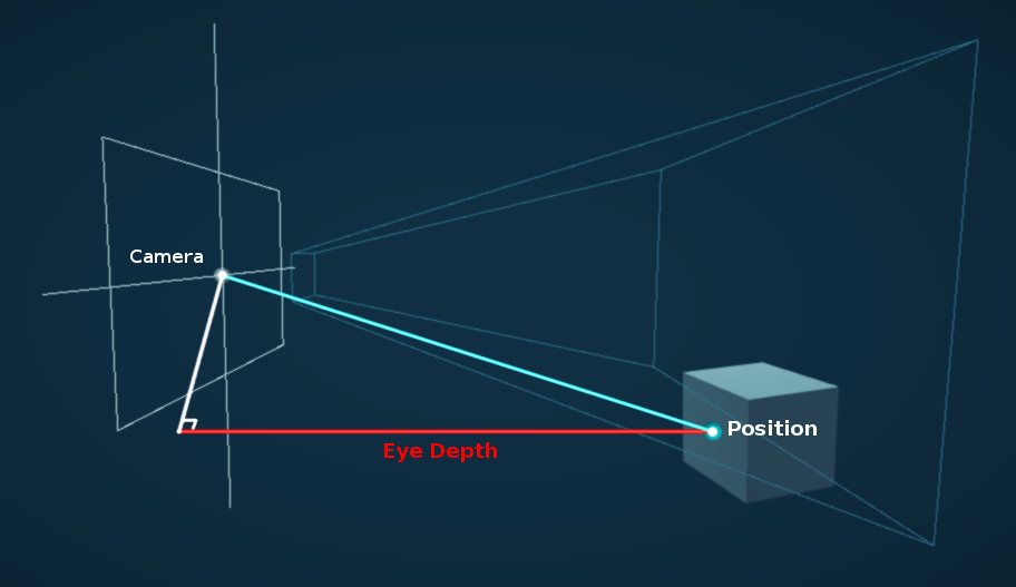
                float nonlin_depth = SampleSceneDepth(IN.texcoord);
                float depth = LinearEyeDepth(nonlin_depth, _ZBufferParams);```
How can I get the depth in world space units / distance?the eye depth is in world space units
Not really
It's the depth in camera space
So it's right at the very center of the view
but obviously the ones as it gets closer to the edge are not correct
I fail to understand what you want, would you like to get the distance from the center of the camera to the object?
this is the eye depth is that not what you are looking for? https://images.app.goo.gl/Z7vHASaa6MaQXQ8F7
Über Google auf www.cyanilux.com gefunden
Anyone alive, I've got a quick question about applying shaders, I'm using the Quibli shader, and whenever I convert any materials to it from the built in rp they just appear white
any ideas on how to fix it, or where I can go to ask?
that musst be then the shaders fault if that isn't their intended behaviour, I am not aware of that shader tho.
Well even ignoring that shader specifically most of the materials, when used on the URP appear either colourless with some texture or completely blank
Like here

What would be a performant way of making a pixel shader for mobile VR? There seems to be a lot of ways from post processing to just scaling down the camera's view or applying a shader to objects.
And another similar question but on color correction. Should I use a LUT or is there a better recommended way?
So happy, got it in the end, just needed to convert the material to urp in rendering
the tiling and offset node in shader graph doesn't seem to have any effect with a texture 2d array sampler? 🤔
How can I use shader keywords?
#pragma shader_feature STORE_DATA
#if STORE_DATA
AppendStructuredBuffer<GrassData> _DataForCollisions;
#endif
[numthreads(8,8,1)]
void SelectIndices(uint3 id: SV_DISPATCHTHREADID){
    if(id.x < _InstancesInChunk && id.y < _InstancesInChunk){
        uint2 xy = id*indexMultiplier+int2(IndexOffsetX, IndexOffsetY);
        uint index = xy.x+xy.y*_TotalInstances;

        GrassData data = GetGrassDataFromIndex(index);
        if(data.height > 0){
            _Indices.Append(index);
            #if STORE_DATA
            _DataForCollisions.Append(data);
            #endif
        }
    }
}
Im trying to get the STORE DATA keyword enabled
            if(VegetationSet.GenerateColliders)
            {
                VegetationSet.DataForCollisions.SetCounterValue(0);
                IndexDistributor.EnableKeyword("STORE_DATA");
                IndexDistributor.SetBuffer(0, "_DataForCollisions", VegetationSet.DataForCollisions);
            }
            else
                IndexDistributor.DisableKeyword("STORE_DATA");
but something is wrong since its not working as expected
there's 3d noise and many variant in github just search it 3d noise github
can someone help me, I modified some blur shader (shaderlab) I found for my needs, it worked fine with orthographic camera but stopped working after switching to perspective camera and I'm not sure why
Hey guys, quick question. How would i go about creating a setup like this that remaps the vertex colour range, but also expose it in the material controls so that you can move the white band up and down the vert colour values to brighten a certain part of the range.. does that make sense? I feel it's a very common thing to do, but I cant think what to search for. anyone know of any tutorials or such that might cover this? cheers

Hey can i get some help plz. Now im brand new to this and idk if this can be fixed, but i have a sniper scope shader setup where if you scale the object it shows more of the screen and when i increase it to a massive size (even tho i dont think i would make a scope that big) it get these stretched UV's

Could be that it's larger than the FOV of the camera producing the texture
not to sure ill have a look, but ill increase camera fov to test out. was looking at my render texture wrapped settings if that helps,
yeah if the scope is larger than the render texture then it will not work properly
any suggestion on how to fix this? looking into the physical cam options now
you could have a script increase the FOV of the camera to follow the fov of the scope
oh my b forgot to say that i change my cams fov from 60 to 120 to see if it would fix the problem and it didnt
did it change the texture to make stuff smaller because if so, then just increase the size of the texture too
it is changing the zoom of everything, but increasing the texture size didnt do too much
the camera I was meaning is whatever camera is making the render texture for the scope
im really confused now but this is what happens when change fov

i've got this sample texture array plugged into the base colour, but the tiling and offset node doesn't seem to be doing anything. how can i control the scale of the textures from the array?

actually no i think i'm just being dumb
hello guys, when building package I have this error:

(sorry for putting an image, it is too many characters to put even when splitting the message)
why is the documentation for the SRPs so awful? BIRP had much better documentation and 3rd party support.
It's constantly changing. It takes time to write documentation, especially when it becomes outdated with the next update.
Is there a performance difference between creating a temporary material from a shader vs using an asset?
Not at runtime, just additional cost during the creation and destruction. You have to ensure that you destroy it when it becomes unused, otherwise it will only be released when Unity loads a new scene.
Is it possible to use RWTexture2D in a regular shader or does it only work in compute shaders
You can have it in a regular shader, you just have to set #pragma target 5.0 or greater.
Or it might be 4.something
It won't be supported on lower end GPUs, but if it supports compute shaders, it supports readwrite textures in other shaders too.
A property value gets messed up somehow. If i use a literal instead it works.
_VertexHeightMapWidth("VertexHeightMapWidth", Float) = 2048

  CBUFFER_START(UnityPerMaterial)
               float _VertexHeightMapWidth;
  CBUFFER_END

Varyings vert(Attributes IN)
{
 //  _VertexHeightMapWidth gives some nonsense value.  Substituting 2048.0f works however.
}
whats the best way in shader graph to take a single channel from a rgb texture, and take the values, whatever range they may be in, and smoothly remap them to 0-1 value range?
No need for all caps text, just start by asking you question ...
If you don't know in advance the min an max of you range, you can't easilly remap it :/
umm i do need the caps (screaming)
ah ok. thats what I was worried about. I'm trying to write a shader that would be robust enough to accept any range and remap it to create a mask that could be edited more consistently by the end user. thanks
Well, in a single shader, while not impossible, it will be hard.
The best would be to compute the min and max values first, and pass them to the remap shader. And to get th emin and max, there is not really any other way than to check all pixels :/
Well, stop screaming, and ask your question ?
umm i need help with normals


im using a texture for the uhh position node
idk what to do im pretty much new to shader grahp
in that case, does anyone know of a good tutorial that would show you how to create something like a plastered wall shader that uses a texture mask to lerp between brick and plaster, but has controls for how much brick is showing through? perhaps i'm going about this the wrong way.
i need help asap :()
Transforming the position doesn't alter the normals, that's why it looks flat.
The best would be to have also precomputed normals with your displacement texture, and apply them to the vertex normals.
The other way to do it is to calculate yourself the normal from the heighmap. The node provided for this sadly doesn't work in the vertex stage, so you will have to do it yourself by sampling multiple times the heightmap : One at the vertex position, one with a small x offset, oen with a small y offset, and compute the normal from all those points using a cross product.
precomputed normal is like the purple looking texture right
i tried it and it looks super weird
That souds like some sort of heightblending
Note that a normal map is in tangent space with "Z" pointing up, where you plane is flat and it's the Y axis that points up, so you will need to swizzle the normal information from xyz to xzy
so i plugged this texture into the normal node using sample lod 2d


oh
yeah i didnt thought of that
i shouldve split them and rearrange them using combine right
let me try
Or use the swizzle node 😄
does this looks correct

whats a swizzle nod
ooo
i have another problem too
when i look in certain angles

the shader turn black like this
what should i do
and what might cause this
im total clueless :()

oo that may come handy in the future thank you mr remy
Is you normal texture imported as normal map ?
Is the normal strength a "correct" value ?
What does the current graph look like ?
its imported as normal map i think i setted the type dropdown to normal in sample texture
and my normal strength is just set to 1
is it wrong
No, should be correct
Oh, did you put the swizzle after of before the normal strength node ? It should be after.
sre
sure
let me clean it up first
its very messy

i hope the nodes are readable
- The split and recombine is not necessary
- The space of the smaple texture 2D LOD node should be "tangent"
- The swizzle is wrong, it should be "xzy"
(for that last point, it does depend on your object axes, but for a unity default plane, it is this)

I fixed this by setting override mode of render objects to material instead of shader
thasnk you so much mr remy
i keep looking for solutions online but it didnt help but urs did!
very cool thanks
Any one here has a Shader Graph sss example shader?

In this tutorial I'll show how I made a fast, lightweight shader for mobile devices using Unity's shader graph.
The shader is based on articles by John Austin and Alan Zucconi, which were themselves based on a GDC paper by Colin Barré-Brisebois and Marc Bouchard.
No, I'm looking for the distance from point on the camera nearplane to the drawn point in the scene.
In order to draw my world space effect only if it is not occluded by geometry
More generally, being able to accurately recover the world space position of the geometry from the depth texture is ideal
I have yes, if I recall correctly that only works for mesh shaders, not screen shaders
So you've tried it?
From a quick glance, I don't see anything mesh specific in it. The only attribute used in the fragment shader is the clip position, which is the same for a mesh object and a fullscreen quad.
You may just have to update the vertex shader to match whatever you need your fullscreen shader to be. That depends on how the shader is used.
Yeah, I tried implementing something similar. I could reconstruct the world position, but getting the actual depth was a little trickier, unless you take the difference of WS positions then sqrt
All in all it was all a bit more roundabout than some random code I found online to compute the view vector, then multiplying it with depth
I'm not well versed enough in matrices etc to convert this to calculate the distance
float3 ComputeWorldSpacePosition(float2 positionNDC, float deviceDepth, float4x4 invViewProjMatrix)
{
    float4 positionCS  = ComputeClipSpacePosition(positionNDC, deviceDepth);
    float4 hpositionWS = mul(invViewProjMatrix, positionCS);
    return hpositionWS.xyz / hpositionWS.w;
}```Here's what the Scene Depth node does in Shader Graph:
https://github.com/Unity-Technologies/Graphics/blob/8872a133378eae31edafc39748ad94b0c6632690/Packages/com.unity.shadergraph/Editor/Data/Nodes/Input/Scene/SceneDepthNode.cs#L102C85-L102C85
Out = LinearEyeDepth(SHADERGRAPH_SAMPLE_SCENE_DEPTH(UV.xy), _ZBufferParams);
@weary dawn
Doesn't that just give eye depth?
My current code which works (for normal rendering (non stereo) atleast) looks like:
            float viewLength = length(IN.viewVector);

            float nonlin_depth = SampleSceneDepth(IN.texcoord);
            float depth = LinearEyeDepth(nonlin_depth, _ZBufferParams) * viewLength;
How could I do this?
float4 veg = tex2D(vegetationMap, uv);
return veg[subindex];
i want to get one of the channels only according to an index
And what's wrong with your code ?
It doesn't allow that kind of acces
Shader error in 'DistributeIndices': cannot map expression to cs_5_0 instruction set at kernel SelectIndices at Assets/Scripts/ProceduralBuilders/ProceduralInstances/Helpers/GetVegetationPosition.cginc(33) (on d3d11)
That's the line
It should, you can access a floatX values as an array 🤔
oh, maybe the error comes from the texture sample float4 veg = tex2D(vegetationMap, uv);
i cannot do that in a compute?
Oh wait, now that I have the attention of someone from Unity, maybe you can help me out to understand if its unity bug or my bug from this
I need some help understanding a bug I'm having. I have a compute buffer containing indices that are important. Those indices are then transformed into position and set on another compute buffer with a compute shader. So
Indices = {1,4,5,8,10}
for loop with indexI of length of indices (5)
{
  get the first indice
  transform it into a position
  verify if position is valid
  if so
  {
    finalpositions[indexI] = position
    finalIndices.append(indexI)
  }
}
the final positions buffer and the final indices bufer are pre seted on a material, all of this has been going on through a command buffer so that each step is sequential
then i copy count the finalIndices length
and I call commandbuffer drawmeshinstanced with the material
the material then does
for loop with indexI of length of final indices
{
  float3 position = finalPositions[finalIndices[indexI]]
  draw the object in that position
}
after this loop is done, the loop is repeated with a diferent set of Indices, while reusing the previous command buffers (final indices with a count value set to 0, and finalPositions untouched)
After all the commands are set, the command is executed at a certain point of the event.
The problem is, the meshes flicker. Is like some data is leacking from loop to loop, or at each loop, data is being calculated slightly diferent (the position seems to be the same, however, slightly diferent since a random generator is returning diferent values)
Im not sure how to debug it, the frame debugger changes the results when checking the diferent steps meaning that it is not returning the same values at each call, even if the calls and the data is always the same
I think there might be somethign about command buffers that I don't understand
Hi. Just started looking into compiling shaders. I'm trying to follow this tutorial: https://www.youtube.com/watch?v=jidloC6gyf8 but I don't get any cutout in the texture. So my question is: what the hell does Active Target mean? Google says I can choose them, but what's "Universal" and what's "Built-in"? When I choose "Universal" and compile, I get 0/49000 in the progress bar (getting to 100 takes 30 seconds so I counted the total would last 4 hours). When I choose "Built in" the progress is like 0/1500 and the compilation finishes in less than 1 minute. Which one should I use? Do I need to use Universal and wait 4 hours to compile 1 shader?


Many games need to make sure the focus is on the player or some other object, and walls are usually a hindrance. You could move the camera past the wall or render things over it.
In this tutorial, we'll just cut a hole in the wall instead. I've seen a wall cutout effect before in a handful of ways, so I'm going to take an alternative approach t...
I'm not 100% sure here, but maybe the order of the finalIndices.append is not constant between calls.
If you are doing the append in you compute shader kernel, maybe the different threads are fighting to write to the buffer.
To sample a texture in compute I would try to use the regular hlsl sample method, not sure unity macros work there : https://learn.microsoft.com/en-us/windows/win32/direct3dhlsl/dx-graphics-hlsl-to-sample
Samples a texture. | Sample (DirectX HLSL Texture Object)
Okay, I did with SamplerState which seems to work
I see, this is how Im doing it
            if(isValid){
                if(dist < _LodDistance)
                    _HighIndices.Append(id.x);
                else
                    _LowIndices.Append(id.x);
            }
        }

        _VegetationData[id.x] = finalData;
So in theory, it shouldn't matter the order of appen since then at the material I do
 uint index = _Indices[instanceID];
 float3 grassPosition = _VegetationData[index].position;
The active target is the renderpipeline that you shader will support. If you'r using URP, choose Universal. If you are using the built-in render pipeline, use Built-in
The thing is, I found this bug issue in Unity Issue Tracker
https://issuetracker.unity3d.com/issues/instances-drawn-with-drawmeshinstanced-flicker-when-the-buffer-changes-order
Which I think it might be related to my case, but since I cannot download the pacakge I don't know if it's the exact same thing Im finding, and im not sure either if it has been updated (since the issue is from 2021)
How to reproduce: 1. Open the user's attached project and Scene scene 2. Enter the Play mode and observe squares Expected result: sq...
Also, you can see the bug here, where the blade changes orientation and details randomly between two random states when just checking diferent frame states
You cannot do the tex2D in compute shader because automatic mip map selection using partial derivatives is not available. You should use version with manual mip specification (tex2Dlod as I remember)
(texturename).SampleLevel(sampler,uv, 0) works
Do you have any update? I'm sorry to bother you, but I've been dealing with this for way too long, so any bit of hope is amazing
Compute shader stuff has no relation to the Unity. Unity just helps executing and creating resources for them. I am 100% sure that it is your issue. Can you show the compute shader code?
I can't share the code for multiple reasons, but the main being that i don't know where the issue is happening. The whole code base is way too big to send it (too many lines in between that are probalby unrelated) But you can find what i'm doing here. I'm 70% sure that the issue is how command buffers/compute shaders work by itself in relation to Unity and it's probably something I don't know about the nature of it
This is what im doing @frigid jay
- here a video of the problem
But I would be more than happy to jump in a call to walk trough it if you'd like, i think it would be way more fast
My only guess right now is that there might be an issue in relation to floating point error, since the problem is that it appears or disappears, something that is related to a random function I have
float3 uRandValue( uint3 x )         // iq version
{
    const uint k = 1103515245U;  // GLIB C
    x = ((x>>8U)^x.yzx)*k;
    x = ((x>>8U)^x.yzx)*k;
    x = ((x>>8U)^x.yzx)*k;

    return float3(x)/float(0xffffffffU);
}

float3 randValue(float3 f)            // $FaN: vec3 to vec3. any scaling. f.z=0 seed is ok.
{
    return uRandValue(asuint(f));
}
So im guesing that if float3 is slightly diferent it will give diferent random value and therefore the change of rotation
The problem, I have no clue how the value could be slightly diferent while still being at the same position (aka the difference is extremely small or im not sure) and having always the same starting position
Calculation of the position
        uint index = _TargetIndices[id.x];
        GrassData finalData = GetGrassDataFromIndex(index);
_TargetIndices returns an index which is precalculated, so it will not change between commands (maybe the position of the index, but that shouldn't be relevant, since everything is calculated in relation to that)
here we have the code that calculates the actual grass data
GrassData GetGrassDataFromIndex(uint index){
    uint x = index%_TotalInstances;
    uint y = index/_TotalInstances;
    float2 fractalIndex = float2(x,y)/(float)_TotalInstances;

    float2 addition = (randValue(float3(fractalIndex.xy, 0.0f)*_MeshScale+randValue(_itemIndex*100)*40)*2.0f-1.0f).xy;

    fractalIndex.x += addition.x/(_MeshScale/2.0f);
    fractalIndex.y += addition.y/(_MeshScale/2.0f);

    GrassData finalData;
    if(fractalIndex.x <= 1 && fractalIndex.x >= 0 && fractalIndex.y <= 1 && fractalIndex.y >= 0)
    {
        finalData = CalculateInterpolatedGrassData(fractalIndex);
    }
    else{
        finalData.position = 0;
        finalData.height = -1;
    }

    return finalData;
}
Since index is always the same i expect the rest of this code to be always the same, between commands
More code
GrassData CalculateInterpolatedGrassData (float2 normalizedIndex) {
    uint2 floorIndex = (uint2)floor(normalizedIndex*(Resolution));
    uint2 ceilIndex = floorIndex+1;

    float2 fractal = (float2)normalizedIndex*(Resolution)-floorIndex;
    uint4 indices = uint4(
        floorIndex.x+floorIndex.y*(Resolution+1),
        ceilIndex.x+floorIndex.y*(Resolution+1),
        floorIndex.x+ceilIndex.y*(Resolution+1),
        ceilIndex.x+ceilIndex.y*(Resolution+1)
    );

    GrassData data;
    // Calculate height with bilinear interpolation of the heights of the nodes of the cell
    float4 result = InterpolatedPosition(indices, fractal, normalizedIndex);
    data.position = result.xyz+worldOffset-float3(_MeshScale,0,_MeshScale)/2.0f;
    float dt = result.w;
    dt += (snoise(float3(data.position.xz, 0.0f)*ExtraNoiseFrequency))*ExtraNoiseScale;

    //Calculate _Displacement through noise
    float grassBladeHeight = (snoise(float3(data.position.xz, 0.0f)*_ClumpingSize)+1.0f)/2.0f;
    grassBladeHeight += snoise(float3(data.position.xz, 0.0f)/10.0f)*_PerBladeVariance;
    grassBladeHeight = lerp(_MinHeight, _MaxHeight, grassBladeHeight);

    //Check vegetation map too
    float chanceToAppear = InterpolatedVegetation(normalizedIndex);
    float closenessToWater = invLerp(0,10,data.position.y);
    float slopeness = saturate(pow(abs(dt),SlopeDampnes)*SlopeStrenght);
    chanceToAppear *= slopeness;
    chanceToAppear *= closenessToWater;

    float randomFactor = randValue(abs(data.position.x+data.position.y+data.position.z)*100).x;
    grassBladeHeight = randomFactor < chanceToAppear ? grassBladeHeight : -1;

    data.height = grassBladeHeight;
    return data;
}
and finally
float4 InterpolatedPosition(int4 indices, float2 fractal, float2 position){
    float FloorX = floor(position.x*Resolution)/(float)Resolution;
    float FloorY = floor(position.y*Resolution)/(float)Resolution;

    float3 pX = float3(FloorX*_MeshScale, heightMap[indices.x],FloorY*_MeshScale);
    float3 pY = float3((FloorX+1.0f/Resolution)*_MeshScale, heightMap[indices.y], FloorY*_MeshScale);
    float3 pZ = float3(FloorX*_MeshScale, heightMap[indices.z],(FloorY+1.0f/Resolution)*_MeshScale);
    float3 pW = float3((FloorX+1.0f/Resolution)*_MeshScale, heightMap[indices.w],(FloorY+1.0f/Resolution)*_MeshScale);

    float3 interpolXZ = lerp(pX, pZ, fractal.y);
    float3 interpolYW = lerp(pY, pW, fractal.y);
    float3 interpolABCD = lerp(interpolXZ, interpolYW, fractal.x);

    float3 interpolXY = lerp(pX, pY, fractal.x);
    float3 interpolZW = lerp(pZ, pW, fractal.x);

    float3 A = interpolYW-interpolXZ;
    float3 B = interpolZW-interpolXY;
    float3 cro = normalize(cross(B, A));
    return float4(interpolABCD, dot(cro, float3(0,1,0)));
}
So, my hunch says that there's something here that could potentially return diferent results between commands, or a problem with unity
Removing all randomness from the previous code still makes it flicker though
So this cutout shader finally works for me. But I'm wondering how would I make it only see through horizontally, without making floor visible? 

Question, a command of draw call needs to be completed before executing any subsequent commands, right?
The problem
Yes.
make a check based on the object normal?
Hey everyone,
I'd like to make the meshes completly invisible. However I only achieve this "slight ghost" kinda look. Any idea what I am missing?

I just found Alpha Clipping as option. It works for what I want. I hope it's the right way
If you want it completely invisible why not turn the meshrenderer off?
Is there an equivalent of "returning early" in the shader graph? Like: if condition, don't do further calculations
I think you're using the transparency blend mode "premultiply" which preserves reflected light on fully transparent areas of the surface
Hi
Just wondering if there's something like the "feedback node" of Touch Designer?
https://www.youtube.com/watch?v=8mWauvn2Gb4

In this TouchDesigner tutorial we look into feedback again and do a sort of particle simulation with a trick from the palette.
I'm also working on a new TouchDesigner + Kinect + Ableton project, stay tuned!
I used this technique for a music video for RackRash Records, which will appear in autumn.
00:00 Intro / Overview
01:11 Setup
02:46...
Or if not specifically in shaders, is there a setup to achieve this?
I guess using RenderTexture somewhere?
what would be the operation instead of multiplication to make the comparison result determine if the dither result should be applied? xD

if comparison == 1 and alpha == 1 then return dither value
if comparison == 0 and alpha == 1 then return 0
if comparison == 1 and alpha == 0 then return 0
if comparison == 0 and alpha == 0 then return 0
wait, actually it's the other way round, black is 0 and white is 1, right
wait, that's what I dont' get, white == no alpha == 1 == non transparent, black == alpha == 0 == transparent
is the preview BEFORE or AFTER the operation? that's what confuses me
1*1 = 1 but I want 0 * 1 = to be 1 when dither is 1 or greather than 0 because of the smoothness
1*0 = 0
0*1 = 0
0*0 = 0
If (!comparison && (dither < 1) ) return dither else 1
how do I write that in node language
I am using Alpha
Never said I want that as a final result. I want to have a noised transparency. Partwise so to say
Alpha blending mode or alpha transparency in general?
You can use multiple Comparison nodes, and combine the bool outputs with logic nodes such as And. (There's also Or, Not and Nand if you need those)
The boolean result would typically be used in the Predicate input on a Branch node, which acts similar to an if statement
Thanks, looks like Branch node is what I need 👍
https://streamable.com/z4l7gs lol, looks like the shader pretty much works how I wanted 😄

now if I only could fix the display of the cut blocks that would be great...
the point is that the transparent circle appears when the guy is behind a wall 😛
im trying to write out the number of vertices seen by a camera to a 1x1 texture. I set ZTest to Always but i still get zero. Here is the shader code:
        Tags {"RenderType" = "Opaque" "RenderPipeline" = "UniversalPipeline" }
        Pass
        {
        Tags {"Queue" = "Geometry"}
        Cull Back
        ZTest Always
        HLSLPROGRAM
            struct Attributes
            {
                float4 positionOS : POSITION;
                uint vertexID : SV_VertexID;
            };
            struct Varyings
            {
                float4 positionHCS  : SV_POSITION;
            };
            uint _numVertices = 0;
            CBUFFER_START(UnityPerMaterial)
            CBUFFER_END
            Varyings vert(Attributes IN)
            {
                _numVertices++;
                Varyings OUT;
                OUT.positionHCS = TransformObjectToHClip(IN.positionOS);
                return OUT;
            }
            half4 frag(Varyings IN) : SV_Target
            {
               return half4(_numVertices / 1000, 0, 0, 1);
}```You can't pass variables from the vertex shader to the fragment shader like this
Either you need to pass it through Varyings, but then each fragment will only get the interpolated value from its three vertices, or create a buffer or texture object that you write to in the vertex shader and read from in the fragment shader.
ok thank you
bump
Blending mode
Then at least in theory I think the mesh should be entirely invisible with 0 alpha without requiring alpha clipping
Hi!
GrassData GetGrassDataFromIndex(uint index){
    uint x = index%_TotalInstances;
    uint y = floor(index/_TotalInstances);
    float2 fractalIndex = uint2(x,y)/(float)_TotalInstances;
    GrassData finalData = CalculateInterpolatedGrassData(fractalIndex);
}
_TotalInstances is an int, is there a chance of FractalIndex being diferent value with same starting index?
This is extremely weird, same index diferent results, floating point error?
im brand new to unity and i cant figure out how to get directional lights and point lights working "properly"
Might be worth debugging in RenderDoc to see the actual values and commands sent to the graphics driver.
i've been doing that, but I don't see any anomaly either
Is there a way to get distance between 2 positions in compute shaders? I tried .magnitude length() and distance() but none of them work.
im having a really hard time googling this so im thinking this might not be possible to do but: is there a way to read a variable FROM inside a shader in a C# script
i know you can use C# to set properties to send data into the shader, i want to go the other way around
I got an error when I tried length(pos1) - length(pos2)
Im not sure why you got an error, but it should be length of the difference not difference of the length
I think it's the same
Hello, It is amazing, how difficult must be to create Outline effect in HDRP....I spent like one day with searching and did not find any functional solution. Is there anyone, who was able to do it without HLSL knowledge?
I carefully read your code snipped and there is no obvious issue in it. As I can see from your video there are two alternating states for your drawings. Whole bunch of things can cause this behavior, so I suggest to go by "simplification" debug method. Simplify your shader by removing parts and finally you can track down the root of your issue. You can replace your rand function by texture lookup too. Use RenderDoc shader debugging functionality. It really helpful.
I did everything you mentioned previously and the error did seem to be happening randomly. I simplified the computes, tried multiple versions of random generators, order of calls, order of commands, etc... At the end I somehow got it working well, still not sure how. I guess one of the changes fixed it, or otherwise it will appear soon again
I think the error came from using scriptable objects and some data not being reseted betwen play modes, which would make (in theory) some play modes have wrong data.
However i couldn't exactly fix the issue, but i have found a way to prevent it for now
It's weird
It's not related to compute shaders or command buffers
Or is the scriptable object thing, or some shaders not being compiled correctly
I also dropped the use of uint to int which seemed ro alleviate a bit
Why might areas of my water shader be invisible when viewing at shallow angles?

It appears to be an issue with the normals, but they're never exceeding (1,1,1)
(or 0,0,0)
is float what used to be Vector1 ?
Yes
ty
hi ,
i wanna hard coding an array or 2 in shader , is it possible ?
is it possible to give value to uniform float test[4]; like test ={1,2,3,4} ?
static const int test[4] = { 1, 2, 3, 4 };
thank you so much ❤️
does any1 know how to fix this?

its a targetting system that is supposed to control the transparency from code which it appears to do in the editor yet in the scene theres no transparency.. shader tips appreciated


https://twitter.com/lejolix/status/894947209892032519?s=46&t=1A3JnRKz0mNHrDv4eDn76A
I need to figure out how to do something like this with ShaderLab.
Wireframe Shader DirectX 11: https://t.co/krXmv29xGx
#gamedev #indiedev #AssetStore #madewithunity
Hey im new to shading and made a simple shader that should set the color to blue and the alpha but somehow on the edges of the terrain there are these weird lightblue things if im far away from it the line thickness is high and if im close to it the line thickness decreases but if im in front of it it is very high again (sorry for my bad english)


I don't really know what you're referring to
Could you show us in game view so we can see what the issue is more accurately?
Also, does anyone know if it's possible to make a surface shader in URP hlsl?
It kinda looks like shadows. Make sure your surface doesn't cast shadows.
Is this still the case? Seems very restricting for a lot of shaders
Yes
hey can i get some help with my shader graph texture. So i have no experience except a few tutorials to get a scope texture up and running. Anyway im trying to make it so the scope is always at 1x zoom no matter the size or position, ive done the size node system and i think thats all working fine, but im struggling with the position part where it is zooming extreamly far out as u move away.

not to sure if this would work, but make some sort of Vector3 origin point that the object position has to subtract? idk
i wrote a vertex shader to write to a RWTexture the number of vertices seen by a camera. But i always get the value '0.1'
            uniform RWTexture2D<half2> _rtMinDistScalpSurfAndNumVerts : register(u3);
            uint _numVerticesUnderPOV = 0;
            CBUFFER_START(UnityPerMaterial)
            CBUFFER_END
            Varyings vert(Attributes IN)
            {
                _numVerticesUnderPOV++;
                _rtMinDistScalpSurfAndNumVerts[int2(0,0)] = half2(half(_numVerticesUnderPOV) / 10, half(0.0));
Can anyone point me in the right direction to drawing lines to create a grid? I thought I had it down but it just keeps breaking...
The lines were black but they randomly turn red for no reason

This is the code that is on the "RenderPipelineManager.endFrameRendering" event

As to why I'm asking in #archived-shaders ... I really think the issue is the material I am using... Or if anyone had any better idea for creating the grid? I duno... Open to suggestions
No idea where the hell it keeps getting red from for one
When I reopen the proejct it's fine
I figured out what causes it! As soon as I select anything in the scene view, it breaks
I turn the grid on and off and it stays red
Hi everyone,
I'm working on implementing Gerstner waves in Unity using the Universal Render Pipeline (URP) and Shader Graph, but I'm running into some issues where the waves are not displaying as expected.
I'm using the Gerstner wave equations to create the effect:
Horizontal Displacement (x in Unity): x(t) = Dx - A * Dx * cos(k(D * P - wt) + phi)
Other Horizontal Displacement (z in Unity): y(t) = Dy - A * Dy * cos(k(D * P - wt) + phi)
Vertical Displacement (y in Unity): z(t) = A * sin(k(D * P - wt) + phi)
Where:
A: Amplitude
D = (Dx, Dz): Direction vector
k: Wave number
w: Angular velocity
phi: Phase
P = (x, y): Position on the water's surface
I've double-checked my equations and the connections in Shader Graph, but I must be missing something. The vector 3 is also connected to vertex position. And if you wonder what the problem is, the plane become invisible.
If anyone has experience with this or sees something I may have missed, I'd really appreciate your insights.
Thank you in advance!
Here's a screenshot of my current Shader Graph setup:

Haven't checked over this completely, but you don't want to Multiply the Position & Direction. You instead want a Dot Product.
Also make sure the final Vector3 is added to the original vertex position (Position node). The final output should also be in object space, so if these calculations are in world, use a Transform node to convert it.
But how do I get vertices data from the voronoi texture?
This is a top down view of my shader applying a texture in the facing direction (so just top to down). How could I make it relative to the current polygon, so the facing direction is of the individual face, not the entire object?
Hey all, I was having a problem that I think probably has a simple answer that I just don't know. I built a simple shader graph that allows me to dissolve out 2d game objects starting at the top and working their way down. It works great right up until multiple of the same object exists in the scene at the same time. It is like it swaps to using world space instead of local space for the height of the effect starting. Anyone know how to get around this?

Does the image show your desired behaviour?
If I had to guess, I'd say if the material is shared, it's can't do 2 different things at once.
Try making a new material when you want to fade out an object
.
I'm having issues with parts of my mesh being visible through other parts, when using vertex displacement in a shader

It looks like this, works fine
But look through it at an angle and you can see the waves through each other
Alpha is set to a constant 1 for testing


This becomes more problematic with complex simulations

Surface Mode set to Opaque seems to fix, but obviously ruins any transparency I may want, plus the normal maps don't work?

Disable, if you want realistic underwater lighting probably easier to do it in a custom shader
Thanks. Looks like I have an even bigger issure than I thought. I expected the attatched material to be a unique instance attatched to the objects similar to how scripts work. I need something that has an effect like the one shown that can be mass produced as needed across multiple 2d game objects some of which are cloned prefabs of one another. If a shader isn't the way to pull that off, then do you have any ideas what might be? The goal is to keep our teams artist from having to manually animate a dissolve effect for every kind of enemy in the game.
Yeah a shader is fine you just need to create a new material instance for each one.
Can probably be done via C#
Perfect. I'll look into it. Thanks a bunch
You might need a pool or something though to prevent creating 1000 duplicates of the same material
Or just dispose when done is what I'd do probably
Any idea if I can create the material as an object in the enemy script? That way, it will be disposed of when the enemy is destroyed.
Looks like I can. Perfect and thanks again for your help
how do i create a shader graph that has a main texture, and then draws another texture based on a stepness threshold value??
Lerp
You get the world space vertex position then process that into a blend amount between your two textures.
this is how sebastian lague did it to the the blend amount in one of his videos, but i don't know how to do this in shaderGraph

i know how it can be done, but i don't know to do it...
you're not providing enough info in your questions
did what?
he just placed grass at a certain level above the stepness calculated in the image
that's what i want to do
My stencil mask is causing horrendous aliasing due to Alpha Clip, does anyone know how to either smooth this out or change how the alpha blending works?
Hello, I'm having a problem with my windows blocking the outside light

Changing shadow treshold on the glass material does nothing whatever the value
If I cutout the glass, the glass itself disappears but the light then goes through

How can I have the light going through AND the glass itself? The frame of the windows still needs to cast a shadow, like this

Here are the settings on the glass atm

Set the renderer to not cast shadows
But if I do that, the frame of the windows doesn't cast shadow either
Like this. I'd need the frame to still cast a shadow

I believe shader graph has a way to specify whether shaders can cast shadows. I don't believe default materials expose it as a setting.
Your other option is to split the object up into multiple renderers.
@vocal narwhal https://forum.unity.com/threads/hdrp-transparency-shader-casts-shadows.619543/#post-4682744
If it's the same property as this thread, it should be the Shadow Threshold but after playing with it, it does nothing. Not sure what I'm doing wrong.
Unity Forum
Glass shouldn't cast a shadow should it? (or at least, not a full shadow)
If there is any way, how do i prevent a transparent HDRP material casting a...
Ha nevermind. Switching to the default HDRP lit and playing with the shadow threshold, it does work. So I guess my custom shader has a problem with this option. I'll test it more. Sorry for the bother.
Ok found it. I had forgotten to check "Use shadow treshold" in the shader graph options so despite showing my custom property, it was having no effect. Enabling the option made it work. Thanks for your help!
Ok I'm having another weird problem with my beard. It appears fine when I'm close up.

But starts to disappear the more I zoom out until it's not visible anymore.

Is there a way to keep the beard even zoomed out ?
Material is opaque so it shouldn't be a transparency problem
Using the HDRP lit seems to work fine so I assume it's another bug in my shader graph but not sure on which side.
Nevermind my last comment, it's also disappearing with HDRP Lit, but less than my custom shader.
Here with the HDRP Lit, the front of the beard is not visible anymore when zoomed out. Really strange behavior

Seems to be a problem with mipmaps since disabling them fix the issue but the texture is too big then
Here with mipmap off on the beard texture. But the beard fickles a lot

bake the beard to texture?
I'm not sure what that means
How could I give the sides of my polygon different texture?

So these parts!

These are all facing out polygons, the walls will always be on a line from origin
This is how I set this up!

I should check for if it's a side before connecting to the third node, but I am not sure how to decide this...
Wait can I just check my UV and if it's the side UV, do the side UV texture!? I think that'd work!!
Usually you'd simply UV unwrap the mesh so each side can have the texture it needs to without any shader math
Or use triplanar mapping
hey can i get some help with my shader plz im trying to zoom my texture when the object is further away from the camera, but its all based on world position atm and when i move my player the texture UV zooms out or in.

hi I am trying to generate a mesh using code and then apply vertex displacement shader to it, but for some reason shader works only on default meshes and not on my vertex grid

is it possible, in the same shader, to read from a texture passed as property and also write to the same texture but set as a RWT?
does your vertex grid have UVs set up
p sure the camera position is world space and you don't want to be combining world and object space coordinates unless you are very sure you need to; you should switch the Position node to be world space
oh, no I didn't, I will try to do it
thanks it works now
okay ill give that ago, been trying to get it to work with screen position and adding a transform with object > view, but ive still got a zoom when it get closer, so just need the opposite i think
just tried it, with position in world but it still zooms when i move
These are the current nodes. when i bring the object close to the camera it zoom in and vis versa for moving it away. i believe what i want is to just change the zooming so when object is close it zoom out for more camera fov.

what does the whole graph look like and what are you trying to do, just to be clear
thx
In terms of what the graph is doing, its a scope texture (crosshair and black ring) and what im trying to do is make it so when the object is close or at a larger scale the scope increase the fov of the texture instead of zooming it in closer, that way i can keep the scope aligned with the world and also have a correct magnification because im handling that another way

^
if the texture is being made with a camera, isn't it easier to zoom in/out the camera via script?
Question:.. if i want to tile a textures channels independendtly from each other ( for masks etc) is the correct way to do that to add a new 2d texture sample node for each channel? or is there a way to use 1 texture sample and edit the tiling after that per channel? also, If i create a new 2d texture sample for each channel (RGBA) each with seperate tiling values but it uses the same texture sample.. does that count as more texture lookups and is more expensive? cheers.

There's no such node
I assume that's a custom function
it is from an old tut
Probably a sub graph
The section before that is creating that subgraph. See 6:40
ok
ah you are right, it is a sub shader, sry pretty new to this thing
i am jsut trying to get refrectation for my water as simple as possible
Does someone has a good learning resource for the topic Clip Space? I am currently watching a Unity Shader course and the explaination about Clip Space in there is very thin. I already checked YT for some videos about this but everyone there is just super fast with the explaination 😄 I need a throughout explaination cause dum-dum
Try reading this article.
https://learnopengl.com/Getting-started/Coordinate-Systems
If you still don't get it, come back here.
Ok now I get it. Thanks!
What could be causing these errors in Freya's Shapes package? I've posted to their forum as well but if you have insight to know how to fix this

I tried reimporting all assets, that did not fix
I don't know what centric or interpolation were (methods? variables?) so I don't think I am capable of just opening that file and adding a definition for them
I can't even find that file in my repo, I assume its a built in unity file?
I found these but none of these are just 'core.cginc'

Question: is it possible in shader graph to use the alpha channel of a normal map, while still keeping the normal map as normal type? i dont really want to be doing all the whole 'unpacking and reconstructing' the normal map from a sRGB type texture.
Freya has a Discord server you could try asking in. centric isn't a built-in identifier, at least.
On some platforms, normal maps are compressed into a specific format made just for normal maps. Those formats won't have an alpha channel, because normal maps don't need them. If this problem can be fixed, it would be somewhere in the texture import settings.
But I suspect Unity will just always ignore the alpha channel if you choose the Normal map type, regardless of whether the texture format you choose supports it.
I thought as much. not seeing anything in the import settings to keep the alpha. though there are options to keep the alpha coverage of mip maps... even when you set it to normal map type. which is kind of odd. thanks anyway
She's here too (Acegikmo) but idk if she'd appreciate a ping
Another quick question: is there a node or a way to have an input for a RBG packed mask texture in shader graph, and then expose a control to the user that would allow them to choose which channel of the packed RBG texture to use as the mask?
It is important to me to have a shader do it, so I could apply one big texture to many polygons to form the original shape ^^
I'm sending the same Render Texture with write enabled to a shader as a property as well as a RWTexture2D. When I read from the Property texture it works correctly but if I execute 'Graphics.SetRandomWriteTarget(2, _rtVertexHeights)' before running the shader I always get a black value.
    Properties
    {
        _rtVertexHeights("rtVertexHeights", 2D) = "white" {}
    }
        HLSLPROGRAM
        #pragma target 5.0
        #pragma only_renderers d3d11

        uniform RWTexture2D<half4> _rwtVertexHeightsIndexedByVertID : register(u2);

        TEXTURE2D(_rtVertexHeights);
        SAMPLER(sampler__rtVertexHeights);

        CBUFFER_START(UnityPerMaterial)
            float4 _rtVertexHeights_ST;
        CBUFFER_END

        Varyings vert(Attributes IN)
        {
          vertColor = SAMPLE_TEXTURE2D_LOD(_rtVertexHeights, sampler__rtVertexHeights, float2(0.5f, 0.5f), 0);  // this works if i DONT execute Graphics.SetRandomWriteTarget(2, _rtVertexHeights) on the CPU side
Hey everyone. Short question from a newbie:
// given
v2f vert(const appdata_base appdata)
{
    v2f data;
    data.vertex = UnityObjectToClipPos(appdata.vertex);
    data.position = appdata.vertex;
    data.uv = appdata.texcoord;

    return data;
}
// ...
float length = length(i.position.xy);
I don't really understand the length helper function here.
The given argument is uhm the two values of the position vector x and y. These are the coordinates of a point.
How or what result is the length between two point values to be interpreted?
I expected something like length(i.positionOne.xy, i.positionTwo.xy) - like a length/distance between two points. That I do understand.
However as shown above the function only takes one vector point and returns me a float value that I can't really understand.
Any enlightenment would be amazing!
What you expect would be distance(p1,p2). But length(p2 - p1) would be equivalent.
In this case I'd probably think of length(i.position.xy) like getting the distance between the point position.xy and (0,0)
ah so it defaults to the center (0,0) point and gives me the lengths towards that. That's why my circle drawing code worked 😄
I haven't done much with RandomWrite targets, but afaik shaders can't read and write to the a given target at the same time. Probably need a copy / double-buffer kinda setup.
hi everyone! I'm having a little trouble using shaders and I don't know why this happens (it doesn't happen in tutorial videos for what I've seen)
for some reason the visible stuff on my sprite is delimited by the orange outline, instead of the whole canvas, so even if I put a blank shader on it, it just covers that part, and that's an issue since I'm working on an outline shader and that limit crops it


is there a way to fix this?
also it probably has that weird shape because of almost transparent stuff I didn't notice, but in other sprites it just covers the borders of the image
In the sprite importer you can set it to "Full Rect" rather than Tight, but there will be more overdraw. You can also draw/generate a different mesh shape, check the "Custom Outline" dropdown in the Sprite Editor window
https://docs.unity3d.com/Manual/SpriteOutlineEditor.html
OH that fixed it immediately, I don't know how I didn't notice that hahah
thank you so much!!!!
what do you mean by more overdraw tho? I'm really new to this, sorry
Where pixels on the screen are drawn multiple times. It's probably the main thing to be careful about for gpu performance.
Having a tighter sprite mesh means there's less pixels to draw (so less likely to overlap with other objects). Obviously some shader effects like the outline might need that extra space, but it still may be better to define your own shape (see link above) rather than use the full rectangle.
ohhh gotcha
now, I'm having a really weird issue tho, since I'm doing kinda the same as a tutorial (main difference is that is an older version so they don't have the main node with color and alpha separated)
I'm doing this thing, just making an offset and getting the extra part to later add them to the main sprite, but for some reason it ends up substracting colors from the sprite

looking like this

I tried different methods of putting the final alpha but none of them worked
(also the outline is semi transparent for some reason)
here's a simpler version, basically the same as the tutorial just with the added step of separating the components of the image at the end to put them correctly in the final node

aaaaaaand it just doesn't show the outline, it just takes in count the alpha of the original sprite, and also the color substract still happens
if I were to do that, i would parent a circle to the gun and apply a mat to it
it what u mean with "circle near the gun" is what i think it is it should do the trick
@autumn ore
if u parent a circle to the gun u would apply the mat the the circle
not the gun player or the bullet
because if u were to apply a material the the gun for example, that material can't create a circle near the gun
how do i install a urp shader?

is this your script? looks like it has an override keyword on a function, and the base class (if there is one) does not define the function as virtual or abstract (overridable).
this isn't my script sadly
just get it in your project assets folder, then you can create materials that use it
does it have to do with volumes?
ohaah
that error is a complier error, it indicates a problem with the code files. don't know if the script generating the error is related to volumes- but can confirm a volume would not generate a compiler error like that.
they are disabled too and it has no overrides
i don't know if that's important
but if i put it on a material it does work so
no, this error has nothing to do with your scene. you could create an empty one, and you'd still get that error. You'd need to fix the error in the code to get rid of it. If you didn't write it, I'd guess some kind of installation error/corruption.
Hey, I'm having issues with my shader graph material turning black when the game is being previewed, but not when scene editting

It used to work fine, and I changed nothing but now it does not work.

The only thing I think I changed might be the lighting?
ahh alright
But the lighting mode is mixed
but it does work. so is there way to apply it on all objects?
because this is meant to be globaly applied
do i have to put it in manually?
@weary dawn hmm.. looks more like it's going transparent than "black"... a clue perhaps?
the errors don't really affect the game,but it's not letting me play it because of the errors..is there way to bypass that?
only by fixing, or removing the script that is generating the compiler error.
The material is meant to be somewhat transparent. It seems to be doing almost everything fine except drawing the right colours / normals
Going to try reverting to a realtime light I guess
It's a shame baking lights takes forever
It's taking 30 minutes on a 3080 in my really simple scene

Yeah seems like a lighting issue, this point light seems to help
alright
this is a shadergraph you created? what does a sanity check of setting the output color to 1,1,1,1 produce?
I don't know why it's happening, I thought mixed lighting was meant to light these dynamic meshes fine?
It's not set to static
Sorry, I've not messed with lighting stuff enough to comment.