#archived-shaders
1 messages · Page 50 of 1
IIUC ....The standard is to orient the tangent in the same direction as the UV.x direction (red) and since the surface normal is oriented at that pixel in the z direction, the bitangent is orthogonal to them both and is the green value in the RGB order. Hence the oft-used TBN matrix...tangent, bitangent, normal. (RGB = TBN ish).
But like Peter226 said, there's a handedness to it and a multiplier in the .w component somewhere.
http://www.opengl-tutorial.org/intermediate-tutorials/tutorial-13-normal-mapping/#tangent-and-bitangent
That's an openGL version, but nice graphics.
Free tutorials for modern Opengl (3.3 and later) in C/C++
Every point on the surface has its own tangent space.
You'd have to pass the object's extents into the shader/material data. You could calculate such a position in the vertex stage relative to the object-space origin (0,0,0) and then transform them to whatever-space.
This is because, by default, you only get the current polygon's info (and really only the current vertex of that polygon at the vertex stage, when not using a geometry stage).
My custom shader doesnt care about enviromental lighting, like at all, could anyone point me in the right direction to make it affect it? 😄
if you are using URP your best bet is to dig around in the default lit shader code, if it's a shadergraph there are a few nodes for it I think but I found that lackluster
there's a thing called block shaders the devs are working on, which will be kinda usable like surface shaders for builtin but with more control
Yeah I only managed to use them to change the color, not affect the actual lighting :/ oh well, thanks anyway!
is there any way i can only calculate it once and then based on it i'll decide if i want to proceed or not ?
btw, thanks for the answer
are your objects the same or different sizes?
and do they need to be different sizes later on
can't you just add an offset to the object position?
could maybe have an exposed variable in the shader that sends the offset so you only need to calculate the offset once
and you can have it different for those two objects
ok tbh idk what i did but the lighting is fixed, the textures however arent
the textures?
materials i mean*
can you post pictures?
yeah hold on one second
ty, how they look and how they are supposed to look
theyre meant to look like this:

wait nvm that scene works
theres one scene that doesnt work
this is what happens when the scene runs through the menu (not meant to happen):

the desert is correct, only the coin is wrong?
yeah
in that case it still looks like a lighting issue to me
if you looks at it closely it has some kind of texture
just too dark
np, maybe if you do have any light probes / baked lighting double check that, can't think of anything else that could cause it
nice, gj!
Hey all, I am working on converting a fog shader I wrote in unreal to unity shaderlab. I am running into a snag on one node in particular which is "TransformVector", which is taking View Space to World Space.
This is the function, and you can see there its transforming a 0,0,-1 vector.

This is the result of the function, and I am having a hard time getting the same behavior in unity. I am avoiding sampling the depth texture and this results in a close enough depth mask for me to use for fog.

https://docs.unity3d.com/Packages/com.unity.shadergraph@14.0/manual/Transform-Node.html
Doesn't work? (There's shaderlab code in the examples. See also BiRP tuts for shaders and TRANSFER_FOG).
Did you duplicate that custom function also?
This looks a lot like unity's depth based fog, BTW. See also:
https://docs.unity3d.com/Packages/com.unity.shadergraph@16.0/manual/Fog-Node.html?q=fog
I’m writing it in hlsl and it’s hard to find documentation
I'm using URP and a vertex displacement shader, It was casting my vertices to a wide range, and I had the camera at (0, 0, 200) and no self casting shadows. I noticed if I move my camera closer to the origin the self shadows to appear. I can probably tweak my shader and scale everything down, but I'd like to understand what the default logic is for displaying self shadows, is it dependent on camera distance or is there something else going on?
The vertex displacement doesn't change the renderer bounding box, so by moving the camera maybe the renderer got out of the camera /light frustum and got culled
hmm... that might be it, the near clipping plane setting seems to affect it. thanks!
https://glowfishinteractive.com/dissolving-the-world-part-1/
These devs had an interesting idea with how they dissolved walls, using a texture with world space uvs to create a mask that dissolved other compatible materials. If you want more of a 'global' rendering option, using renderer textures with a mask and sorting what gets rendered between the layers instead of relying on the object's material. There's also some nice tools outside of shaderlab called render objects, which are available on srps, that I found pretty easy to use for this type of stuff.
Hi, I made this simple dissolve shader but the problem I'm having is that it isn't affected by ambient lighting, it's pitch black if there's no directional light. Any idea on how to fix it?

This is not quite what i was looking for, but great nevertheless. Thank you very much for it :D
Yeah np, I do use the render objects for walls in my isometric game and they do work pretty well for that specific case
Hello, I'm trying to fix the transparency issue in my hair shader in HDRP. I've already tried to play with depth prepass, depth postpass and cutout value but I can't get a good feeling out of it. If I cut out too much, the hair becomes fully opaque which defeats the purpose of transparency.

Howver I noticed that if I simply duplicate the hair and stack it on top of itself, the transparency gets much better.


Is there a way to reproduce this stacking effect directly in shader graph? Maybe through postpass in some way? So that I don't have to duplicate the model?
But what pipeline? I assume one of the newer ones, as the BiRP has a bunch of HLSL doc, as that's how it is written.
Anyway, yeah, I can imagine it's tough.
Cyan has a site with docs. See stick pin above.
Also, you can use shader graph to generate the code for you and then examine what it generated. It's really a code generator anyway.
Then there's the unity source code for the shaders they use, in the code repository for your installed version.
And of course lastly there's the web and varied resources.
Yeah I am using BiRP
I know it’s something simple it’s just hard to identify the right property to grab
But HLSL and the unity API are pretty well documented for BiRP.
https://learn.unity.com/tutorial/writing-your-first-shader-in-unity#
https://docs.unity3d.com/Manual/shader-writing.html


Unity Learn
In this live training session we will learn the fundamentals of authoring shaders for Unity and you will learn how to write your very first shader. No prior knowledge of authoring shaders is required.
Here's some samples, that include unity fog.
https://docs.unity3d.com/Manual/SL-VertexFragmentShaderExamples.html
The code to do the transformation that you asked about above is in the node example from the shader graph link I posted earlier if you want to do it that way.
Hey guys, can you help me with a question? I'm trying to make a tileable shader that sets textures based on position (or at least that's what I wanted to do) this is my graph:
Basically it works perfectly, exactly as I wanted when the object's scale is large, but when the scale is low, the texture is stretched instead of tiling correctly, is there any way to fix this so that the Atlas texture is always on top , the middle one always in the middle and the bottom one always on the bottom? without stretching of course


https://i.gyazo.com/93e48d99357bad322d411d47d94f5efc.mp4
The effect I want is exactly this:
(effect of using a tileable UI panel with rect tool)
Neat, I'd assume you need some ratio between the tiling and the scale amount, but there's always some easier way to go about it
Check out wrapping mode maybe
Same results :/
x_x
So I've got shadow casters on my sprites, but it's a little iffy considering I also billboard them towards the camera and by not rotating the direction the shadows they cast. It creates problems such that the self shadowing darkens the sprite at specific viewing angles. Seems a little complicated to resolve, unless anyone has any ideas, otherwise I'd probably want to disable the self shadowing if that's possible at all with shadow casting. Actually doubting this is even that possible considering it's just a quad...
Does anybody know if there are any restrictions regarding texture channel packing? I have 4 greyscayle textures: two albedos, two masks. I want to merge them into one packed texture. red would be albedo1, green is mask1, blue is albedo2 and alpha is mask2.
Here is my custom sub graph to extract the channel dynamically (Can't use the buit in one since the channel can change depending on packing configuration) I want use a vector4 input. x would be red, y is green, z is blue and w is alpha.

The preview seems to work fine but the actual result is different than expected.
Here is when I use a texture where I packed albedo1 and mask1 into one single texture

And here is when I use a full packed texture.

Each are using the adequate channel but in the second picture, the alpha seems messed up.
is it not possible to pack a mask texture into something other than alpha channel or grayscale channel?
Here is a better comparison. Left is 4 packed channels, right is 2 packed channels

The left one has much more transparency than the right one despite both using the same mask. The difference is in left one, I packed the mask in the green channel and in the right one, I packed it in alpha channel.
Hm, after checking the preview in my custom sub graph, both channel do not render the same for some reason. I guess my packing script has some flaw. I'll investigate :x
That or my sub graph logic is flawed too.
Hm, I've checked my packing and both channels are exactly the same...
but the preview still shows different results
My logic seems flawed in the sub graph?

My idea is still to mask 3 channels and just keep 1 based on a Vector4 mask. I multiply each channel by the related mask channel and then take the max out of any of those to get the final result.
I tried to preview the green and alpha channel on each of the textures but I forgot alpha is ignored in preview node :/

But even like this, it seems my green channel preview is not the same as original.
Some semi transparency is lost on all edges
Have you tried looking at the compression settings of your texture, and if you're not importing it as Linear, switching to that?
Indeed, I thought about that. But both are using the same settings. I figured the main preview had alpha working so here is the difference. Straight from green in 4 packed and straight from alpha in 2 packed. Really strange

Both files have the same settings


The same settings can be compressed differently across channels. Have you tried linear, which is switching off SRGB (Color Texture)?
Oh indeed. Unchecking the box now shows something closer than the original
Great, it's the same now
Thanks a lot for your help! So many settings to understand :x
@vocal narwhal Would you by any chance have some insight about this one? Semi transparency is a bit clunky and duplicating my model does seem to reduce the clunkiness. If I understand well, I'd need a way to impact transparency after the shader rendered? Is it possible to have the same visual of those 2 stackigns hair models but using only 1 model?
It's complicated and there are many options to consider that all have their own drawbacks https://unity.huh.how/graphics/materials/rendering-issues/transparent-materials
Got it, thanks for the link!
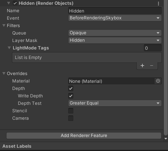
How do I write a depth only shader with HLSL for URP? Everything I tried only works when I also output color.
You can use ColorMask 0 so the colour buffer isn't edited
Oh yeah just figured out I already had it working. It just did not work as I expected it to. It will just not clear this part of the image 😬
could experiment with stencils or different ztest modes depending on desired result
I figured it out using stencil buffer. I was already using stencils as a render feature and wanted to avoid explicitly setting the stencil in the shader again. But it turns out that was the easiest solution
Hi! I need some help optimizing this shader i've ben working on
I wrote a fragment shader that returns .5 for RGB. But in the Unity color picker the color is not 128,128,128 for RGB. This is a clean new project using URP. Why?
fixed4 frag (v2f i) : SV_Target
{
fixed4 col = fixed4(.5,.5,.5,1);
return col;
}
I mentioned the other day that I am working on converting a shader I had made in unreal for non-depth buffer accessing fog. It relies heavy on this vertex depth function. I am using BiRP, but have not been able to get it to function properly. I was able to make it in shadergraph, as you can see here, the math works, and the mask cascades into the distance. When trying to do this in hlsl, I cannot get proper results, its as if the worldPos, and cameraPos in Standard Surfac input are not correct.

It's to do with gamma vs linear colourspace. https://docs.unity3d.com/Manual/LinearRendering-LinearOrGammaWorkflow.html
Possibly also post processing.
@regal stag thanks I've been searching for hours to try to find out why this is happening
Is there a way to have a stencil shader ONLY RENDER what's inside it, and not other objects that are behind but don't have the material/shader applied?
Basically I would like this floor not to render through the stencil shader

source image

So, you want the windows to render through everything, along with any object the window itself is rendering?
ah, ok I see what youmean
Something like that?


I'm not sure what objects you're trying to render without the material, but you can instead just use render objects and do it by layer if you wish

The "other objects" would set the stencil, saying in effect "don't render floor here". The floor shader would honor the stencil and not render pixels where the stencil is set. This happens because the frag() function won't be called for those pixels that do not pass the stencil test.
Of course, all the other objects would have to be rendered first, and the floor last.
I'm new to shading, and I have been stuck on this issue for a while now, but it seems really simple. How do I give the shader a vector2/float2? (writing a compute shader)
Any idea why these Materials are not in sync with the textures?

Should be able to use float2 _someVector; on the hlsl side (global scope) and computeShader.SetVector("_someVector", value); on the C#
https://docs.unity3d.com/ScriptReference/ComputeShader.SetVector.html
As it's magenta, I would assume the shader being used by the materials is not suitable for the current render pipeline set in the project.

That won't make URP run shaders that are made for built-in RP. They need different shaders
the "MenuHome.glb" is imported through "GLB Importer"
using these 2

oh
@regal stag Could you please give me a hint where to search so I can import different shaders?
(like, what type of tutorials should I search for)
Okay I see now, the GLTFUtility has shaders for both Built-in and URP. You need to use the ones under the GLTFUtility/URP heading. You can change the shader at the top of each material asset.
Though if these are embedded materials from import you might not be able to edit them directly. I'm not sure if there's a way to tell Unity to automatically use the URP ones... But should be able to create your own materials and assign it under the "remapped materials" in the model settings. https://docs.unity3d.com/Manual/FBXImporter-Materials.html
Okay, I will try it and I think it will work.
You were really helpful, thank you very much!
UPDATE: It worked perfectly!
Thank you again for your help @regal stag !
Yes exactly that!
So you used render objects instead in that screenshot?
Oh wait, is the texture applied to the object or is it something "inside it", not exactly that probably then.. I'll still look a bit into it though.
Also, are render objects URP? (I'm using built-in)
I'll see if I can wrap my head around this, I'm still pretty bad at everything shaders.
Here's the code I have if you don't mind directing me more:
        Pass
        {
            ZWrite [_ZWrite]
            ColorMask[_ColorMask]

            Stencil
            {
                Ref[_StencilReferenceID]
                Comp[_StencilComp] // always
                Pass[_StencilOp] // replace
                ReadMask[_StencilReadMask]
                WriteMask[_StencilWriteMask]
            }

            CGPROGRAM
            #pragma vertex vert
            #pragma fragment frag

            fixed4 _Color;

            struct appdata
            {
                float4 vertex : POSITION;
            };

            struct v2f
            {
                float4 pos : SV_POSITION;
                float4 worldPos : TEXCOORD1; // fog
            };

            v2f vert(appdata v)
            {
                v2f o;
                o.pos = UnityObjectToClipPos(v.vertex);
                return o;
            }

            float _FogDensity, _FogOffset; // fog
            float4 _FogColor; // fog
            half4 frag(v2f i) : COLOR
            {
                /* Fog */
                float viewDistance = length(_WorldSpaceCameraPos - i.worldPos);
                float fogFactor = (_FogDensity / sqrt(log(2))) * (max(0.0f, viewDistance - _FogOffset));
                fogFactor = exp2(-fogFactor * fogFactor);


                return lerp(_FogColor, _Color, fogFactor);
                // return _Color;
            }
            ENDCG
You'd need the render order to be stencil window -> then all other objects. Can force that by using the Queue tag or override the render queue on the material. Can then have those objects test against the stencil buffer. The white objects you have there are already doing that. You'd do the same for the floor but using a NotEqual comparsion.
If you're in URP, you can use RenderObjects features to override stencil values for an entire Layers of objects without needing custom shaders.
An alternative to stencils is to use an additional camera & render texture, similar to rendering "portals". Might be a bit more expensive though.
ehm, there's no metalness when using SSS with the StandardLit ?
What's wrong with the refraction?


Creating custom shadows is very tricky but when shadows are enabled for the shader, self shadowing should work automatically
How about, is there ways to remove self shadowing when casting shadows? ^^
Hey, my colleague has implemented cellular automata based water fluid simulation. (Compute shader)
I see in his implementation, an index can be changed/written in different threads. Is it OK?!
The operator is +=.
buffer[index]+= diff[index-1];
buffer[index]+= diff[index+1];
//...
if the same index is written and read in different threadgroups it can cause issues and some values will be random, consider atomic add operations or memory barriers with group sync
when appropriate
looks like there's a diff buffer tho, I guess the diff buffer is calculated beforehand? if there's a memory barrier group sync after the diff buffer calculation then it's okay
Thanks but using atomic add is not efficient.
I don't access his code but I can put it tomorrow, appreciated.
Sorry my wrong. It is the opposite direction something like below
buffer[index-1]+= diff[index];
buffer[index+1]+= diff[index];
//...
Allright, ping me when you posted it here, if I see it I'll take a look
It adds the current value to its neighbors
He is intern and probably his code has a lot of bugs
would do the same, no?
Yes, I have said to him
but he said the cellular automata based water fluid simulation is not similar to standard cellular automata!
I try to convince him
Yeah, thats expected tho, compute shaders aren't the most straightforward thing to be honest 😄
what do you mean by this?
"cellular automata" is very broad
He found the code written in C# script and tried to convert it to a compute shader version
ahh, yeah makes sense
needs a bit of tweaking then, but he's got the right spirit 😄

He wants to resign 
Yeah I've done something similar just with velocities incorporated
Jeeez, why so soon? 😂
does he not like the job?
He does not like cellular automata especially compute shader and now even water.
Oh man, that would be a job I'd love to work on 😆
Guess some prefer normal gameplay programming
Not really, the shadows are rendered separately onto a texture, and that's what every object uses for shadows. Unless you can afford a lot more latency for rendering all shadow casters except your object, then normally render your object before everything, then render the object's shadow, and then render everything else
Ah, that's unfortunate. Trying to figure out some realtime shadows with sprites, but there's a large peter panning issue I'm having and I've no clue how some 2.5D games manage it all
doesn't help I've got full 3D camera rotation on the sprite which is a problem of its own
wait, you are doing sprites? can you send a pic of your scene and what needs no self shadow?
Easily solveable by just not allowing to recieve shadows, but I've spent a week to actually get that correct lol
my thinking is I need to reduce the bias (or offset?) of the shadow when the shadowing is behind the character
but then I would still run into the panning issue (shadow isn't completely under feet)
idea 1 (the simpler) is to push back the shadow map's value inside the player's shader, so it need something "more above" to create a shadow
idea 2 is to write a custom shadow rendering pass where you also render the ID of the topmost object with it's depth value in the shadowmap
but it's REALLY time consuming
and in this case, if the topmost object's ID is equals the current object ID then we don't need to shadow
by more above, you mean that a shadow wont render on the sprite unless the depth of it all is at a specific height?
I was thinking of something like that if that's the case, but that would then affect the shadowing of the geometry of the level (on the sprite)
it's kinda like a custom depth bias just for that object
that's "easier"
you need to copy the lit shader's code, and re-define the part in the shadow calculation code after importing it, where it reads the shadow map
OR the value of the depth bias global variable 🤔
that may be easier now that I think about it
Yeah, more technical then I thought it all would be. Really would have loved to do something with just light layers, but that doesn't seem possible.
yeah, shadows are kinda their own species
I'll look into your suggestions, but if it comes to this maybe I should look into just making my own silhouette and rendering that on the ground of sorts.
another sprite ;p
oh yeah that would work too 😄
ty though
np
I don't have any shadow on builtin unity, on urp i had them, how can it be?
So i have a problem and a question at the same
I have a image with sprit renderer in a 3d project
I have also List of points of vector3
I wanna make of that image a heatmap where it is full of green and on those given points
does it get red and you know orange yellow
any way how to do it?
How can I handle it?
I want to use sprite renderer with order + cutout shader.
Anyone who can possibly help me out with a shader issue? I feel like I am really far, may just be moving things around, but I can't seem to get there.
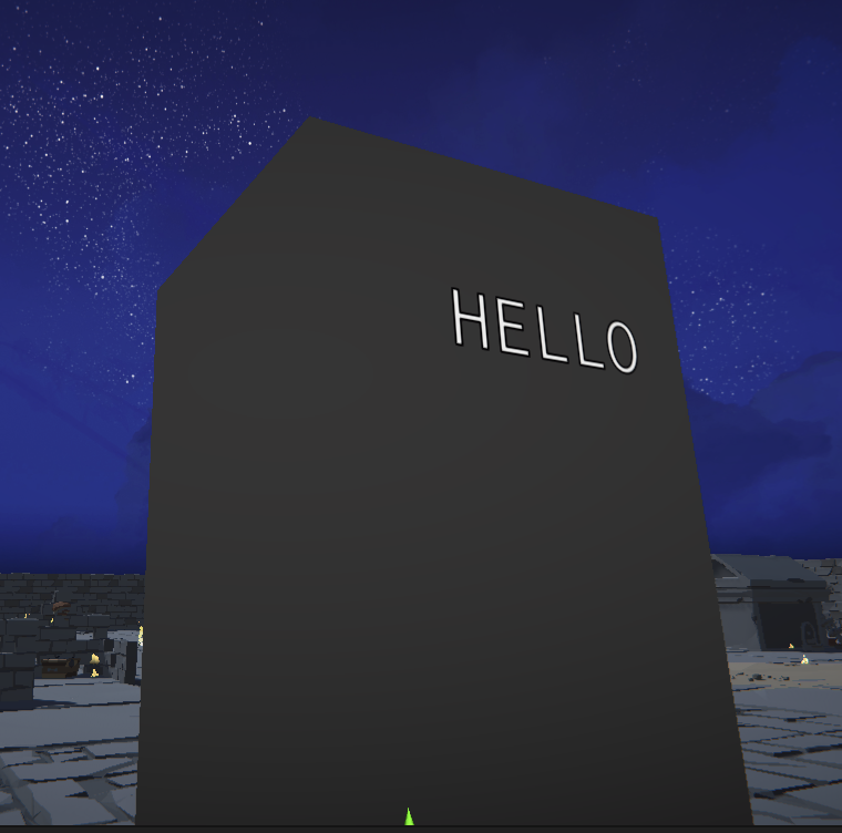
I have a shader in which I'm trying to add a cutoff, where the top part doesn't get rendered based on an Ycutoff float. Right now it's just making things white within or the whole top white.

If you join Unite in Amsterdam, I can offer you a beer for this 
Are you asking how to handle the cutoff? Is this shader code or graph?
Yeah, struggling with it. It's shader code and shaders are really not my expertise
It's just a pass I added at the bottom, but its just making things white
Pass
{
Name "CutOff"
        CGPROGRAM
        #pragma vertex vert
        #pragma fragment frag
        #include "UnityCG.cginc"

        struct appdata
        {
            float4 vertex : POSITION;
            float2 uv : TEXCOORD0;
        };

        struct v2f
        {
            float2 uv : TEXCOORD0;
            float4 vertex : SV_POSITION;
            float3 worldPos : TEXCOORD1; // added this line
        };

        sampler2D _MainTex;
        float _CutoffValue;
        float4 _ObjectBounds; // add this line to get the object bounds

        v2f vert(appdata v)
        {
            v2f o;
            o.vertex = UnityObjectToClipPos(v.vertex);
            o.worldPos = mul(unity_ObjectToWorld, v.vertex).xyz; // added this line
            o.uv = v.uv;
            return o;
        }

        fixed4 _TopColor;

        fixed4 frag(v2f i) : SV_Target
        {
            fixed4 col = tex2D(_MainTex, i.uv);

            float relativeHeight = (i.worldPos.y - _ObjectBounds.y) / (_ObjectBounds.w - _ObjectBounds.y);
            if (relativeHeight < _CutoffValue)
                discard;

            return _TopColor;
        }
        ENDCG
    }
Just a copy of the default unity "Standard (Specular setup)" with this pass added at the bottom
You can't add it as a separate pass, that renders the mesh twice. You need to alter the main pass
Ahh, makes sense. I assume the main pass is in this case the "FORWARD"
If you're in the Forward rendering path yeah. For the deferred path there's probably a gbuffer pass. You may want to add the cutoff to multiple passes.
I added it above ENDCG on every pass. Issue might be the frag
#pragma vertex vert
#pragma fragment frag
#include "UnityCG.cginc"
        struct appdata
        {
            float4 vertex : POSITION;
            float2 uv : TEXCOORD0;
        };

        struct v2f
        {
            float2 uv : TEXCOORD0;
            float4 vertex : SV_POSITION;
            float3 worldPos : TEXCOORD1; // added this line
        };

        float _CutoffValue;
        float4 _ObjectBounds; // add this line to get the object bounds

        v2f vert(appdata v)
        {
            v2f o;
            o.vertex = UnityObjectToClipPos(v.vertex);
            o.worldPos = mul(unity_ObjectToWorld, v.vertex).xyz; // added this line
            o.uv = v.uv;
            return o;
        }

        fixed4 _TopColor;

        fixed4 frag(v2f i) : SV_Target
        {
            fixed4 col = tex2D(_MainTex, i.uv);

            float relativeHeight = (i.worldPos.y - _ObjectBounds.y) / (_ObjectBounds.w - _ObjectBounds.y);
            if (relativeHeight < _CutoffValue)
                discard;

            return _TopColor;
        }
Thank you so much though @regal stag I can play around a bit more with this, don't want to take up too much of your time ❤️
The passes already have their own vert/frag shaders in the include files (UnityStandardCoreForward, UnityStandardShadow, UnityStandardCore, etc.), you'd need to copy & edit those. But if you're in the built-in RP it might be easier to look into writing a Surface Shader instead.
Yeah, just using the build in render pipeline. I was just hoping to copy the Shader "Standard (Specular setup)" and add a cutoff. Didn't think it would be this difficult 😂
Been messing around with it for 2 days now, even bought gpt4 to no prevail
I should learn Shaders a bit more properly at some point, this is just donig random things you don't fully understand and hope it works
I managed to get a cutoff working in the shader editor, but can't seem to add the texture and holes to it 
Hi everyone :),
I'm trying to do a tornado shader for my study project but there is a line on the side of my tornado and it's ugly 🥲
I don't know if this problem coming from my blender model or if it can be solve somewhere with unity somewhere.
It's maybe appear because i'm using noise but i'm not sure :/ I'm in URP.
Some help please ^^'

Both your wind texture and mesh UVs need to be tileable / repeating
There is no wind texture, it's a noise with twirl and a dissolve, but i'm going to try to switch my noise by a repeating noise texture.
does anyone have any feedback on how i could improve the look of this water shader? It moves and the colours are quite nice but I think the normals look quite flat. It would be nice if the waves were more promenant

hey guys, i have a simple question: why can't i multiply these two?

You can't use sample texture 2d going in the vertex space
swap it out for a Sample Texture 2D LOD node, i had this issue
i think that's the right explanation
Yeah, in the vertex function you need to choose the LOD level yourself, so you need that node
Hey.
Hoping someone can help me out with a shader problem.
Might be trying to do too many things in one shader but lets see.
Currently using built-in rendering.
I just want a standard shader that can clip up to a certain worldPos.y on the second camera (minimap) using plane clipping. I couldnt find the code for the current Unity standard shader so using: https://github.com/TwoTailsGames/Unity-Built-in-Shaders/blob/master/DefaultResourcesExtra/Standard.shader...it might be the current, not sure but it does the job.
Then tried to implement: https://www.ronja-tutorials.com/post/021-plane-clipping/ on top of it (but editing for the second cam) and mash them together.
Got mixed results lol.
I can get it clipping well or rendering well, but it messes up when trying to do both.
Code: https://gist.github.com/Unrelentless/cb8f1d7ae771838ea16562843a8fc346
What am I missing in the clipping subshader to get it rendering those leaves nicer? Or do those two methods just not mesh well together?


Summary Another cool effect is to make the surface disappear when it’s beyond a certain plane.
To follow this tutorial, it’s best to know how surface shaders work - you can find a tutorial how they work here.
Define Plane We start by creating a new C# script which will define the plane we use later and pass it to the shader. It has a material as...

Gist
Standard Shader + Clipping. GitHub Gist: instantly share code, notes, and snippets.
yeah he's an explanation of using Sample Texture 2D vs Sample Texture 2D LOD

Thank you guys! That makes sense :) (btw, am I allowed to say thanks in this chat?)
of course!
I gave up 🙃
I cannot see any reflections or refraction. There are no waves or vertex displacement. And that normal texture you slapped onto it doesn't look at all like waves. And there are also no specular highlights
there is vertex displacement when the scene is played
I agree though
I've tried some new normal maps
i'll take a video
this is the new normal maps. think it looks better though i have set it quite strong at the moment

I'm going insane due to something strange with transparent materials in stand-alone builds.. By using RenderDoc it looks as if my UV coordinates gets messed up in the fragment shader somehow... This is my issue

Its so simple its stupid.. Switching the shader to opaque instead of transparent and everything works as intended.
RenderDoc also tells me that the UVs are OK both pre and post the vertex shader step.. (I'm rendering a simple quad here, so its quite easy to verify)
I try to use a render texture that uses a camera that can only see a layer with these ball things then I made a material with this render texture and I put the material in a flat quad but for some reason the quad is darker then the camera and I don’t know how to fix this issue

Hello there, I have encountered a grabpass issue on built-in rp
Recently, I've been working on a large project involving the Pixel Perfect Camera and Canvas space effect. Specifically, I applied a grab pass shader to a full-screen image component for filtering purposes. However, I discovered that when the pixel perfect camera is set to the mode {Pixel Snapping, CropFrameXY, Stretch Fill}, the grab pass effect (material attached to the UI image component) appears stretched.
To provide a clearer demonstration, I have attached a simple project that you can open and follow these steps to reproduce the issue:
` - Open the project and adjust the resolution setting in the game view to "Free Aspect."
- Click the Play button and resize the game view to different aspect ratios.
- You will observe that the game view displays the stretching problem.
- To resolve the issue, disable the image component under the canvas, and the stretching will no longer be visible.`
Please note that in this project, the included shader merely captures the image behind it and renders it directly. In the actual project, there are several shaders based on this one, and they function correctly when attached to the sprite renderer.
(From Unity Forum
quad is probably lit or you gave it a color
huh.... I was told this was supposed to make the plane invisible, did I do something wrong?

figured it out 
You'd need to enable the "Opaque Texture" on the URP asset

what is the step node coming from?


np
for some reason the objects with my shader only render when the render queue is above 2500, any ideas? https://pastebin.com/AeKC1YTn sorry about the left over comments that don't make sense


Pastebin
Pastebin.com is the number one paste tool since 2002. Pastebin is a website where you can store text online for a set period of time.
fresh project with that shader
is works with the prebuilt shaders and shader graph shaders though
And you're using URP? Maybe try removing the constraint urp tag from it
I am using urp, and nothing changes if I remove the tag
https://i.imgur.com/hdsmz0C.png
plugged it in without any changes and it works with my URP project
I'll try changing the unity version
nope
I'll just restart my computer
maybe I'll just use shader graph but write the entire thing in a custom function node
thanks though
seems to work after switch to an even newer one
What's the right way to set material properties for individual objects? If I apply the same material to 10 objects, but want them to behave differently depending on object properties? (As an example, a material that is more red if the character's HP is low)
It's likely because of this : https://www.cyanilux.com/faq/#urp-depth-priming
But yeah, if you can recreate in shader graph that may be easier.
I've heard if you set material properties directly you either make new materials or alter the material for all objects using it
From a C# script, if you use GetComponent<Renderer>().material it'll create a clone of the material so .SetColor/SetFloat/SetVector/(etc) methods will only affect that object.
While renderer.sharedMaterial or a serialised reference to the Material asset would indeed affect all objects using that material.
You can also set properties on a MaterialPropertyBlock, passed to the renderer via renderer.SetPropertyBlock. (That's okay for Built-in RP, but would avoid that in URP/HDRP when working with MeshRenderers, as it breaks the SRP batcher compatibility)
I'm using a 2d renderer, URP. Does that affect your suggestion about MaterialPropertyBlocks?
Basically mostly sprites
Also, would using material property blocks even once completely turn off SRP batching, or is it a "The more you use it the worse it gets" type situation?
I don't typically work in 2D so not sure. I don't think sprites use the SRP batcher (yet) so it might be fine to use MPBs there over material instances. But either way it'll still break the dynamic sprite batching (unless the shader also supports GPU instancing). For only 10 or so objects that may not be a big deal anyway.
If you just want to make a character more red, you could use the SpriteRenderer.color field which uses vertex colours so doesn't need separate materials.
It only affects the SRP batching for those renderers the blocks are set on. But only MeshRenderers (& SkinnedMeshRenderers) use the SRP batcher anyway.
It was just an example. Don't actually want them to be red, but do kind of want to set shader properties based on buffs etc on my units
like, intensity of effects
Another option could be to render effects with an additional transparent sprite over the top of the regular one.
I remember I came across a tutorial on grass that moved when the player got close, so I knew there was a way to do it reasonably.
That makes sense, and then maybe add more transparent sprites if I want to have more effects apply at once?
Would work for stuff like glow
That's a bit different. That likely uses the players position sent into a global property and the shader compares the distance against that. It's still the same material for all grass blades.
Ah, and if it's a global property it would not work if I for example had multiple units?
So the player can move grass but enemies can not, for example
because it's just a vec3 of the player position as a global property?
With that example yes, it would only work with a single unit. There are also methods that use render textures that could work with multiple.
Similar sort of idea for leaving trails in snow
yes, this fixed it in the original as well, thanks
Right, thanks for the info. I'll take a look at render textures and global material properties
I am trying to use a transparent material on my model in unity but you can see the back side throught the front of it? I don't know why

It's on the bottom face of the arrow. The face should be hidden from this angle, so I don't know why I am seeing it here. This issue doesn't happen if I have the material as opaque
May be interested in this post : https://forum.unity.com/threads/transparent-depth-shader-good-for-ghosts.149511/

Unity Forum
So one of the things you will encounter when rendering complex meshs' using standard transparent rendering is that they depth test against the scene,...
Thanks, I found a shader that fixes this issue. I don't know how to write shaders yet unfortunately. But now it doesn't disappear fully with 0 alpha 😭
That's due to the mode used for alpha blending. If it's a surface shader, alpha:fade should make the whole object disappear at 0 alpha. While alpha:premul doesn't affect the specular iirc.
This is the shader I am using. How can I get it to fully dissapear at 0 alpha? There is only one alpha setting that I can see in the editor, idk how I would change it to use alpha:fade
I think it's Rendering Mode : Fade, rather than Transparent
That was it! Thanks, I got it working now :)
Hey there, I purchased a Polygon food pack recently, and I've just tried to import it into a URP project, and the shaders are all broken.
Is there a way to convert them to URP, or do I need to have a non-URP project?

if they are custom shaders you need to use a non urp project
They are, although it says it supports URP so I'm not sure if I'm doing something wrong or not
Edit ^ Actually they're not custom

if thats the case you can just use the auto convert button
If I am correct, I should be looking in Window > Rendering > Render Pipeline Converter?
yeah
Does anyone have an example of the correct syntax to sample a texture inside of a custom node of shadergraph?

I am struggling to find on google the correct variables to pass in and the syntax to then sample it
sampler, samplerstate, unitysampler, others
Tex2D, texture2D, UnityTexture2D, I'm not finding the correct syntax on google
void SampleTex_float (UnityTexture2D _tex, UnitySamplerState ss, float2 UV, out float4 sampledtexture)
{
    sampledtexture = SAMPLE_TEXTURE2D(_tex, ss, UV);
}```Does this look right?
yay it worked

trying to convert a shadertoy to hlsl, what is an ichannel and where do I plug the SS?
im not sure why there is a random , in the method, im assuming the ichannel is the texture, then the UV, but whats that third value
i would like to create a outline shader for a plane without doing fancy depth stuff. just a simple plane with a boarder. i currently have this which is working ok:
but as soon as i change the scale of my plane the outline width changes. does anyone know how to fix that?


The width changes because the UV channel in that direction is getting squished when you scale it. To fix this you'll have to take the object's scale and multiply the UV by that axis in some way

I dont know the exact steps to solve it, but that's the problem at least
There is no third value, the UVs are : uv+vec2(cos(d),sin(d))*Radius*i
what is that apostrophy doing then?
uv+vec2(cos(d)
and
sin(d))Radiusi
I'm trying to port a shadertoy glsl to hlsl but not having much luck
OH its uv + vec2(params)
I was having difficult parsing it visually
https://www.shadertoy.com/view/Xltfzj
void mainImage( out vec4 fragColor, in vec2 fragCoord )
{
    float Pi = 6.28318530718; // Pi*2

    // GAUSSIAN BLUR SETTINGS {{{
    float Directions = 16.0; // BLUR DIRECTIONS (Default 16.0 - More is better but slower)
    float Quality = 3.0; // BLUR QUALITY (Default 4.0 - More is better but slower)
    float Size = 8.0; // BLUR SIZE (Radius)
    // GAUSSIAN BLUR SETTINGS }}}

    vec2 Radius = Size/iResolution.xy;

    // Normalized pixel coordinates (from 0 to 1)
    vec2 uv = fragCoord/iResolution.xy;
    // Pixel colour
    vec4 Color = texture(iChannel0, uv);

    // Blur calculations
    for( float d=0.0; d<Pi; d+=Pi/Directions)
    {
        for(float i=1.0/Quality; i<=1.0; i+=1.0/Quality)
        {
            Color += texture( iChannel0, uv+vec2(cos(d),sin(d))*Radius*i);
        }
    }

    // Output to screen
    Color /= Quality * Directions - 15.0;
    fragColor =  Color;
}```
The shadertoy

```csharp
void GaussianBlur_float(float Directions, float Quality, float Size, float Radius, UnityTexture2D _tex, UnitySamplerState ss, float2 UV, out float4 outColor)
{
    float Pi = 6.28318530718;
    float4 sampledtexture = SAMPLE_TEXTURE2D(_tex, ss, UV);


    // Guassian Blur
    for (float d = 0.0; d < Pi; d += Pi / Directions)
    {
        for (float i = 1.0 / Quality; i <= 1.0; i += 1.0 / Quality)
        {
            //sampledtexture += SAMPLE_TEXTURE2D(_tex, uv + float2(cos(d), sin(d)) * Radius * i);
            sampledtexture += SAMPLE_TEXTURE2D(_tex, ss, UV + float2(cos(d), sin(d)) * Radius * i);
            //sampledtexture += SAMPLE_TEXTURE2D(_tex, ss, UV);
        }
    }

    sampledtexture /= Quality * Directions - 15.0;
    outColor = sampledtexture;
}```

My port of itIm making mistakes in my port though because the output looks wrong
instead of gaussian blur it just looks.. wrong, and im not sure why

I assume the problem is I've made mistakes in porting it, but I can't find my mistake 🤔
vec2 Radius = Size/iResolution.xy;
this line I didnt know what to replace it with because I dont know what iResolution is or what it should be for me
that is because you have uv as input. Use object space vertex positions instead for sampling it
like this? doesnt seem right :(

ires I realize is for shadertoy's preview window, I think I just need UV there 🤔
try tiling and offset node into the UV, -0.5 offset both axis
position is 0,0 at center whereas UVs are 0,0 at the bottom left corner
so you'd need to offset it to account for that
mh doesnt work. tried both -0.5 and 0.5. both doesnt work

Change the preview from 3D to 2D
its working but you can't see it off the edges of the sphere most likely
i fixed some of my mistakes but im still not getting the expected result from this


hm its almost working if I set size to be extremely small, but I dont know why this is the case

well my plane is completly black when i do that :(
Radius = size / input texture resolution.
Did you apply this ?
TEXTURE resolution? Not the uv coordinates?
the shadertoy has 'iResolution' google says that value was the height/width of the screen itself
Look at those two lines from the original code :
    vec2 Radius = Size/iResolution.xy;

    vec2 uv = fragCoord/iResolution.xy;
First is used to define the blur radius based on the size, second are for UV coordinates
And the radius is 2D
my understanding of that is that iResolution is the size of the viewport on shadertoy. So to get UVs they have to take those values and make them a range of 0 to 1, but a UV map already does that for me in Unity
Where am I incorrect?
iResolution.xy is the shadertoy rendering resolution => your texture resolution in shadergraph
I critically am not understanding why its my texture resolution
I dont want to just go 'okay ill just assign it the texture res' because I dont feel like I am learning why its wrong, and wont be able to fix any future problems because I dont understand the fundamentals
Neither is your code posted here : #archived-shaders message
nor your last screenshot shwong where the radius value is comming from, this is probably the error that make it "work" when size is very small
Neither is your code posted here
I am not sure what you mean by this, could you clarify, neither what?
the test texture is a crate thats 512 512 so Ill try passing in 512 as the iResolution?

not that I understand why at all
The shadertoy effect is bluring a texture that is applied "fullscreen" on the viewport. But you are trying to blur a single texture (unless you're doing a post process effect maybe ?). So the iResolution from shadertoy translates to the texture size
You don't even need to pass it, iirc shadergraph has a node for it, or you can use hlsl GetDimension
I was just trying to say that I have no idea from where the "Radius" value can come, because none of the informations you gave showed it

vec2 Radius = Size/iResolution.xy;
Yes, than you , I saw the original code, I was talking from your code
it didnt make any sense to me so I failed to translate it properly because I have no comprehension
which is why I dont want the answer but the understanding of why and how it works because I lack the comprehension
The code you shared seems to have Radius as an argument of the function, but it was not visible as input of the node after, so I don't get it.

here is my untested code as of right now
I probably changed something in my attempts to fix it and didnt screenshot the inbetween
Also, just for facts, you can also do a cheat blur effect by sampling a lower LOD of the texture.
Hey, I am new to unity and I need help. I can't really turn off the unity filters off or find where it was. Do you guys have any solution?
What do you call "unity filters" ?


This is where you get mad at me because this is entirely an XY problem and I dont want gausian blur at all, I want to fix my REAL problem which is that my texture is pixelated as fuck and I want it softer
Its a camera captured render texture so I dont know if it even has LODs
no LOD's that im aware of

Or when I click play it doesn't show in the game
You don't need to adjust the UVs in your case
Search for the post processing component in your scene
It's "Enable Mip Maps"
I will finish correcting the current method then look into sampling LODs like you said if gausian isnt performant enough for my needs
I crashed unity by giving it a negative number accidentally so currently reimporting
Ok, so while it is restarting :
The line float2 adjustedUV = uv / resolution is useless.
in shadertoy, there is no UV input, that's why they do fragCoord / resolution it's the pixel coordinate (+1 per each pixel) / the resolution => the UV
Since you are already passing the correct UV to the function, no need to correct it.
Okay so I understood that shadertoy has no UV, but I misunderstood that the -other- use of iResolution was not related to UVs but to the texture resolution

Yeah, disabling post processing here can also work.
Not really a shader issue though, you'd better continue in #archived-urp
Oh alright! Thank you!
@amber saffron its working-ish. Currently the texture is very bright but when you rotate the preview, it flickers to the correct lightness sporatically.
I am guessing the problem has something to do with floats?

void GaussianBlur_float(float Directions, float Quality, float Size, float resolution, UnityTexture2D _tex, UnitySamplerState ss, float2 UV, out float4 outColor)
{
    float Pi = 6.28318530718;

    float2 Radius = Size / resolution;
    //float2 adjustedUV = UV / resolution;

     float4 sampledtexture = SAMPLE_TEXTURE2D(_tex, ss, UV);

    // Guassian Blur
    for (float d = 0.0; d < Pi; d += Pi / Directions)
    {
        for (float i = 1.0 / Quality; i <= 1.0; i += 1.0 / Quality)
        {
            //sampledtexture += SAMPLE_TEXTURE2D(_tex, uv + float2(cos(d), sin(d)) * Radius * i);
            sampledtexture += SAMPLE_TEXTURE2D(_tex, ss, UV + float2(cos(d), sin(d)) * Radius * i);
            //sampledtexture += SAMPLE_TEXTURE2D(_tex, ss, UV);
        }
    }
    sampledtexture /= Quality * Directions - 15.0;
    outColor = sampledtexture;
}```
Im not sure what that magic - 15 number is or if its related to the problem
I think that 15 is a hard coded value that the person forgot.
The idea is just to get the average value for all the pixel samples, so divide Color by the number of samples
Which value is the samples? Quality? The number of times that the for loops maybe?
If you don't want to calculate them, you could just add a counter 😄
Like so?

Yep, but it should start at 1, as you have one sample out of the loops
Oh good point
and at the end, just /= samples
Hey that worked AND it fixed the flicker problem
so it was the magic 15, huzzah

void GaussianBlur_float(float Directions, float Quality, float Size, float resolution, UnityTexture2D _tex, UnitySamplerState ss, float2 UV, out float4 outColor)
{
  // directions = 16
  // quality = 3
  // size = 8
  // resolution = input texture resolution
    float samples = 1;
    float Pi = 6.28318530718;

    float2 Radius = Size / resolution;
     float4 sampledtexture = SAMPLE_TEXTURE2D(_tex, ss, UV);

    // Guassian Blur
    for (float d = 0.0; d < Pi; d += Pi / Directions)
    {
        for (float i = 1.0 / Quality; i <= 1.0; i += 1.0 / Quality)
        {
            sampledtexture += SAMPLE_TEXTURE2D(_tex, ss, UV + float2(cos(d), sin(d)) * Radius * i);
            samples++;
        }
    }
    sampledtexture /= samples;
    outColor = sampledtexture;
}```working guassian blur for anyone who wants it
Now remove the resolution input and use GetDimensions 🙂
https://docs.unity3d.com/ScriptReference/Texture2D.htmlI cant find the property or function to run for that 🤔
float resolution = _tex.GetDimensions().x; wasnt a thing
maybe width or height, ill try that
invalid subscript 'width'
Returns the dimensions of the resource. | Texture2D::GetDimensions function
oh I dont have a Texture2D though, I have a UnityTexture2D
_tex is not a hlsl texture object, but a UnityTexture.
You can get the underlying texture using _tex.t iirc
invalid subscript t, trying to google it
now getdimensions wants parameters, reading that method now
Returns the dimensions of the resource. | Texture2D::GetDimensions function
it returns nothing?
Nope, it has out arguments
oh
Just like your custom function 🙂
collosal error
I wish I was smarter and could understand how to find the answer without so much handholding

You need to provide the 4 required arguments of the syntax
this is beytond anything ive ever done, how will it know which OUT to pull from?
``` is this right? I dont know what miplevel I want, 1? 0?You want mip 0
How do I cast the uint to a float, will that implicitly just work in shader?
isually it gets mad like "cannot convert uint to float"
You can cast explicitely like this : float width_f = (float) Width;

Yes, you are defining it at the same time you are calling the function here, but you can as well define it outside
I still get the error above, no matching 0 parameter instrinisc method
even though I'm not passing any zero methods
so ive made a mistake for sure

this seems like a huge painful run around just to get width
If you want the dimensions of a UnityTexture2D, can't you use _tex.texelSize.zw?
Ah, yes .. true
Or if you're doing / texelSize.zw, doing * texelSize.xy should be slightly cheaper
@amber saffron sorry for dropping off on replies I had an hour apointment, reading your and cyan's messages now
After lunch Ill try this method out 👍
This worked, thanks both of you 👍

i have a problem with a 3d masking shader im using, im trying to mask a door that slides up and down and before it was clipping through a wall so i decided to add a mask above it. here's how it looks (LEFT) what it's supposed to look like (RIGHT)


so for some reason it just got rid of the texture
(this is using a mask shader)
and the mask isn't working at all
shader code```c
Shader "Custom/Mask"
{
SubShader
{
Tags {"Queue" = "Transparent+1"}
Pass
{
Blend Zero One
}
}
}
masking code```c
using System.Collections;
using System.Collections.Generic;
using UnityEngine;
public class MaskObject : MonoBehaviour
{
public GameObject[] ObjMasked;
void Start()
{
for (int i = 0; i < ObjMasked.Length; i++)
{
ObjMasked[i].GetComponent<MeshRenderer>().material.renderQueue = 3002;
}
}
void Update()
{
    Vector3 mouse = Input.mousePosition;
    Ray castPoint = Camera.main.ScreenPointToRay(mouse);
    RaycastHit hit;
    if (Physics.Raycast(castPoint, out hit, Mathf.Infinity))
    {
        transform.position = hit.point;
    }
}
}
hey im following brackeys tutorial (https://youtu.be/NiOGWZXBg4Y?list=PLPV2KyIb3jR6Wxj8HaJ_pZhBtaamtXL7J&t=116) on shaders but the pbr graph isnt showing up. im using 3D (URP). any fix?

(ping me pls)
It's now just shader graph rather than PBR graph (the node is also renamed from PBR Master to fragment + vertex)
when I use fresnel on a 2 sided transparent shader, the entire mesh looks uniformly/heavily affected by the fresnel effect. I think it's the backface causing this. Why? and can I resolve this?
Shader graph or code?
@regal stag shader graph
You need to use a Is Front Face node then, into a Branch. Either to remove the fresnel for backfaces completely, or to flip (negate) the normal vector.
Works flawlessly, thank you. Does this mean that whenever rendering backfaces for whatever reason, flipping the normals will always give me the proper normal for the given backface? @regal stag
I guess so actually, it'd make sense. Forget I asked
Does anyone have a detailed explination of HDR color intensity math?

For example in this picture I am writing those cubes to a 32bit texture and multiplying by 0.2, I would expect the 10 Intensity block to resemble a 2 intensity block but that's clearly not how this math functions 🤔

so Intensity must be something other than just color+++
I think HDR colour is rgb * 2^intensity
Oh a power 👀
Does that mean I want to logarithm the texture? Or the multiply value has to be.. an exponent relative to the input color?
the XY goal I am seeking is just better control over the output
trying to go from "that looks nice/right" to "I have exact control over all of this"
hm, multiplying the output by ANY value seems to completely ignore the higher intensity cubes
they all get darker/lighter perfectly identically, expected output would be the far left one would get darker faster than the far right
maybe my problem is in the render texture itself

Bloom post proccessing gets brighter the higher the intensity is as expected 🤔

Ill do more googling
🤔


float intensity = Mathf.log(factor) / Mathf.log(2);
I'm obviously making a mistake because of my lack of comprehension
what values should I be logging in? The log function doesnt say what base
doesnt clarify it to my comprehension
if I dont add that tiny ammount it also blows up completely

How do I debug a shader when I have no idea what of the 1000s of things could be going wrong and all I have is a texture that i cant even eyedrop a value to find out what it is
this HDR texture thing isnt working and I have no idea why or how to determine why
log(0) is undefined which is why it breaks
the values in this texture SHOULD be HDR values

but my output is not HDR (I think) because it wont behave like other HDR values
and I dont know why or how to make it be HDR

which of these 600 formats is right, because I googled it and tried the ones who said they encode HDR values, and they dont for me
or maybe the problem is the shadergraph, or URP itsself, or literally anything
no way to debug because you cant debug shaders

if it was encoding correctly, I would expect the value under the glowing cube to be glowing just as brightly
because that is bloom on an HDR color
so because its not glowing, then there's no way that encoded value is in the HDR range
I'm just guessing here but it might be that the R32G32B32 colours are still normalized (0-1), and that the texture itself is saved in a way that clamps all the values
Do you think there might be some setting somewhere to force it to not normalize?
IF that even is the case?


I would guess the way to do it is to use some higher-precision texture format but have all the colors divided by e.g. 1024 or something, then you multiply by 1024 in the shader but again just guessing
NOW its glowing when I set it to this but it definitely wasnt before


Yeah thats actually what I was trying to do here all along
I was multiplying it by 0.2, that last cube is Inensity 10
but the output wasnt intensity 2
instead it was 0.2, as if clipped to 1 before mult

Like why

as I multiply it, the expected is the far left one would get darker first, and the glowing one last
but that is not at all what I am getting
its 100% being clamped somewhere somehow but how do I stop that
https://discussions.unity.com/t/hdr-data-is-not-rendered-into-render-texture-when-using-urp/231826/3
Unity Discussions
I’m trying to do a similar thing in unity 2021.2.15f (latest unity version at the time) using URP. I’ve got a sun (sphere) with a material with a HDR emissive colour with an intensity of 10, I render this to a cube map using this code: public class CubeMapGenerator : MonoBehaviour { public Camera Camera; public RenderTexture RenderTexture; ...

this persons sollution doesnt work

anything wrong in here?
how do I get a reference to a render texture to run this method on it?
its not a thing I can assign to

I am so stuck and so lost
why does it feel like everything I try to ever do something no one has ever done before ever
can't find a droplet of answers on google
my head is so deep in the forest I can no longer see any trees, putting this to rest for tonight

if the render texture / shader / camera / anything was displaying an HDR value, that purple would be glowing like the purple on the left
its not glowing so its clearly not HDR
its picking up the HD glow values but its clamping them to 0-1
and I dont know how to stop that 🤔
Unity Forum
I've written a custom skybox shader and the texture I'm using is an HDR formatted texture. Sampling the texture directly via tex2d clearly leads to...
maybe the problem isnt the texture but the sampling of it
If there's post processing enabled on this camera, the resulting texture could have tonemapping or something applied, which would convert the HDR values to SDR

I was sampling it with sampletexture2D
now im trying to sample it some other was in case that was clamping it
except im getting the error no matching 3 parameter function
even though its right there and its 3 parameter
and that exact syntax worked in other shaders
Hmm, I think SAMPLE_TEXTURE2D should be fine
so once again Im doing something wrong and dont know what
im getting too worked up to solve effectively because I desperately want this to be overwith solved
I know I used lesser methods in shaders in other projects, ill open one and search the codebase
Unity Forum
Hi everyone,
Unity default skybox shader samples a cubemap like this
half4 tex = texCUBE (_Tex, i.texcoord);
half3 c = DecodeHDR (tex, _Tex_HDR);...
I need to replace sample texture 2D with DecodeHDR
but I dont know how
its what I must do but I cant find the answer on how to do it
nothing makes any sense
just going to give up and close up
Hey, I'm trying to make a simple vertex rotation shader, but my mesh is also skinned to a parent bone. When I use a position node as my input on the rotate about axis node, it's taking the position of the bone the mesh is skinned to, not the mesh itself. Is there a way to change the position pivot to local to the mesh/object, not the bone it's skinned to?
i made a shader that simulate the heat distortion
and i wanna use it for other reasons, so how can i make it on the screen like a canva
the shader is applied to a quad
What is Unity calling PBR Graph Shadder now?
not in built in I think you will need to write your own
If you go through the shader graph docs, or by right clicking on the nodes you can grab the generated code unity puts into them
Lit shader
Hey, how should I go about making an animated shader graph that flickers the emission like a candle?
*I know that the below screenshot is completely wrong I was just testing stuff out

Hello, I read some time ago that branch nodes should be avoided since they are not that optimized? Could someone give me more details please?
plug time into sin wave mutliply it with some speed and some amplitude and plug it into the strength
It's a bit of a large discussion.
It's not that bad if you're branching based on a uniform value (one passed in that is constant for all pixels in the frame for that shader).
The problem comes when you have a situation where the condition is different for different pixels in the same work group. Remember that GPUs are massively multi-threaded...so you could have 64, 128, etc. threads in a group running IN PARALLEL at once...all sharing the same instruction/program counter.
So what happens is that if thread 32 has to take the top part of an "if" condition, and thread 33 has to take the "else" part of the condition, ALL 128 THREADS have to "march" through BOTH sides of the conditional. So you incur the performance penalty of executing BOTH sides of the condition and you don't save anything.
This isn't too bad if your condition is something like "if (foo) then blue else red". Two small statements...meh. Unless you're real tight on your rendering budget it probably won't matter much. And using a ternary operator IS a conditional, just like an "if".
Sometimes you can get around it with math, but often "jr." programmers end up using a conditional in the math to get to a 0 or 1 value to multiply by!
All you can really do is try things and benchmark your specific set of conditions. Big flags should go off in your head if you have a conditional where (A) it isn't a uniform value and (B) you have a big block of code for the "true" side and another big block of code for the "false" side. Or really any big block of code that isn't based on a uniform....know that you'll likely get the performance cost of ALL the code.
But if ALL threads can skip a chunk of code, they should.
There's also dangers of disabling some optimizations if certain code is embedded in a conditional, like I think some texture reads that are dependent on something, particularly bad are texture reads dependent on other prior texture reads (DTR).
I see. So as long as both sides are quite small, it shouldn't matter too much then? I'm trying to optimize my game and use channel packing technique where albedo (grayscaled), bump and alpha are all merged into the same image, 3 different channels, and I might pack another image. Sometimes, I might not need an alpha channel, so I can pack 2 albedos and 2 bumps in the same images. Meaning alpha might not always be in the image alpha layer. And I'd like my shader to be flexible: All textures will have an albedo, but might not have an alpha or bump. And sometimes, the bump or alpha might come from another image too. So I was thinking of having 3 texture inputs for my shader and use branching to determine if alpha and bump have been filled. By using a Vector4 mask on the RGBA then getting the max value out of the mask, I get a single float which would be grayscale value of albedo, alpha or bump. My issue is how to determine which input will give me the bump and alpha. Could be coming from the main albedo texture or from another texture. That's where I was thinking of using branching.
But I'm thinking maybe it would be easier to simply feed the same texture to both inputs? Though it would be sampled twice for nothing? Is sampling an image a heavy operation if it's the same image ?
GPU's are built for sampling but it isn't free. They are time offset. When a sample is pending, the thread is assigned other work and it comes back to it later, kind of.
But
What you MAY want is shader variants. Depends on your use case.
How many variations you have on a theme. For each binary-thing..."has ALPHA" or not...you get a variant.
So if you have one keyword for "HAS_ALPHA" and another for "HAS_BUMP" you'd end up with 4 variants...2 squared.
00, 01, 10, and 11 in a truth table. Each time you add a variant keyword, you double the number you had before. This also incurs a penalty for the executable code size and memory footprint as each shader variant is just that...another copy of the shader.
But things not used are compiled out...saving execution time.
Ok. I thought about it too but I was worried about the number of variants it adds. I know Unity strips them on build but it already builds so many shader variants i'd rather not add more if I can avoid it.
I'm thinking I might simply add 3 masks (albedo_albedo, albedo_bump, albedo_alpha), on the main albedo, 1 mask on the bump (bump_bump) and one mask on the alpha (alpha_alpha) inputs. This way, if I have the bump texture on the main albedo green channel, I could set albedo_bump to 0,1,0,0 and the bump_bump to 0,0,0,0 then get the max out of each float?
I still use sampler nodes for bump and alpha but I'm guessing if I don't fill the texture slot and leave a black color input, than no sampling occur in GPU?
And I would avoid using branches or variants.
Would this solution be more efficient than branching or variants? I have no clue
I do have 5 Vector4 masks information to fill each time but that might give me the flexibility I want while keeping the shader optimized?
Make a test project, and some different shaders, and test it out in isolation. Benchmark, basically.
GTG, good luck, maybe others will have more input.
Im trying to make my own shadergraph so the player can customize their color, with an option for gradients in different directions. Currently it does make a gradient if the user chooses updown, leftright, or frontback but it also lerps the red, green, and blue value. I understood why it does this, but I dont know what to do.
How can I get this so the player can choose red/green, and then LeftRight, UpDown, or FrontBack so the red to green gradient happens in that direction?

theres more to the graph thats unrelated, but this output goes straight to Base color and alpha
I think chaining the branches would work (so output of one into False input of the next). Last one would go into the T input directly, the Vector4 is not needed.
Though that does mean some will take priority over others, kinda unavoidable with bools. If only one should be active at a time it might make more sense to use a Enum Keyword instead, that way you also get a dropdown in the inspector.
I was considering allowing multiple at once if it just worked, but ill try that rn ty
Might also want to add an option to offset/remap the value & Saturate before connecting to the lerp too
I will attempt to understand what that means, im just a dev who cant afford an artist :p
And adding an Inverse Lerp or Remap (from MinMax property to 0,1) would let you choose where the gradient should start and end across the mesh
Saturate will clamp the values between 0 and 1, as currently the position can be negative or higher than 1 and the lerp will continue to extrapolate the colours, might be a bit odd.
wow ty that enum works! What happens when the (1) output goes to T(4)? I assume its affecting every value

oh i see, thats actually what i need now because the gradient is kinda just happening in the middle
Basically going from value to float4(value, value, value, value); which is what you want, as you want to lerp the same amount across all colour channels (otherwise you get the problem you started with)
I'm having an issue with the normal from height node in shader graph

I get a lot of flickering over the face
If I use a normal map texture, I don't get this flickering
What could cause this flickering?
It's more visible in this one
I can't figure out what's the problem. It's as simple bump map with a simple normal from height node.
I have an old 3D vertex-painted mesh whose color data are in UVW.
Is there any way to get that W in Unity? Look like it's stripping that value no matter what and only keep UV.
If you mean uv coordinates, they are 2D, there is no W. How was it authored to make a W?
With custom in-house tools from the PSX era (Spyro the Dragon's skyboxes, to be precise).
The .obj must contain that W since I have a viewer tool who does display them correctly.
well, you're going to have to re-author it externally so it's normal afaik. Unity's mesh representation does not have a W coordinate, and I doubt it's interpreted by the OBJ importer. I see that the w coordinate is for nurbs geometry, which is not supported.
Crap. Well, time to see if Blender can save the day then.
Thanks for the answer.
can i use a shader on ui ?
Does anyone know why this shader would be invisible? Using URP
Thanks 🙂


because you didn't transform your vertecies to clip space
ill have a look into it
thanks for the help 🙂
perhaps the scale/resolution is off so it's almost random from pixel to pixel
when sampling the texture, try multiplying by some very small number and seeing if that improves things
Sorry for bothering you but ive done this here:
but it still produces the same results. Anything that might be wrong with it here?
also of note: the shader works in the material preview

Another reason why it may be invisible is due to URP using Depth Priming to prime the depth buffer, but the shader doesn't have a DepthOnly pass. More info here : https://www.cyanilux.com/faq/#urp-depth-priming
Might also be easier to use Shader Graph
i have been considering shader graph but I want to try out writing shader code as generating noise in the shader graph might be a bit difficult
but thanks for the help 🙂
also gotta say your site is very useful ive used it for a fair while now
You can use Custom Function nodes with HLSL include files for the actual noise generation code
true that
Adding the depth passes to the shader worked!
Thanks 🙂
Is anyone familar with .shaders in SRP and URP? I am trying to convert this .shader to work in URP that was original made for SRP.
If anyone thinks they can help, feel free to make a thread on this message 🙂
How can I make a render texture an HDR texture? How can I debug where in the following flow that the HDR values get stripped out?
URP 2022.2.17f1
I have a cube with a high intensity HDR color value material on it. This value is HDR.
I have a camera pointing at it that outputs to a render texture. The color format is RGB32SFLOAT so it supports the HDR range of values
I have a plane that displays the render texture.
I have a global post processing volume with bloom.
The problem is somewhere along that line the color values get clamped to 0-1, the plane doesn't bloom glow and all that extra data is stripped out. Is there some way I can force or bypass the problem to be sure 100% the HDR values are getting encoded?

here is a version I faked that I am not happy with - this was done by lowering all the colors into non-HDR value ranges then multiplied back up again

while this 'works', its very not WYSWIG and just adds an extra layer of spahgetti to break making controlling the desired output look that much harder
Would anybody have some insights regarding this issue? A bump map with a normal from height node flickers like crazy for unknown reasons. Using a real normal map without the node doesn't have this issue
vs all the same length because the HDR isnt being encoded while WYSWIG correct HDR material colors

guys, im working on the sprite of capsule, I want to make it have two colors, one on the outside and one on the inside, how do I do that?
the way i am thinking about it, it should be copying the UV and scaling it, (that's the step that i can't do the rest is easy)
RenderDoc will let you investigate each draw call and inspect the pixels to see when the colors are clamped.
Ill look this up and try it 👍
apparently you can encode HDR textures as RGBE where the E is for Exponent, not sure how you would generate such a file and I think you need a special package to import/use them
yeah im currently thinking the way I sample the texture might be clamping it to SRGB ranges, when I want to sample its raw data values which in theory are in HDR ranges
How do you write a sampler yourself in the shader? I googled and couldnt find, and GPT doesn't know what it's talking about when I ask it
I am thinking my problem is the normal sampling method is returning SRGB and I am trying to return its true linear values
so I am trying to write acustom function node that will use a Texture2D<float4> and sample that to get the real values

this is xy - how do I sample a unitytexture2D and get its linear values without converting to SRGB? for this specific texture, not the entire project
The texture is not a texture, its a Render Texture, so I can't simply 'set it to linear' or do anything related to texture import settings
If it's a HDR texture format (i.e. R32G32B32A32_SFloat), it is already linear and not using sRGB.
I'm also not convinced that tex.Sample is the problem
Neither am I but I am just exploring every possible thing I can explore, because I am completely utterly blind with no means to determine what's wrong, I just have to keep trying every possible thing until I stumble into the answer
Someone mentioned a RenderDoc thing Ill look at that again
Is post processing still enabled on the camera rendering to the render texture?
Yes for sure

Disable it, you don't want it enabled
jfc 👀

unchecking post proccess fixed it
the HDR values are sustained
I have no words but gratitude
The post processing likely includes tonemapping which is what is converting the HDR->SDR. You typically want that for the final image, but not for intermediate render textures
How can i get multiple fragment shader outputs using blit in a renderer feature pass? My frag shader outputs a color and a depth map and i need to use both of them in another pass. But blit only has 1 target to copy to.
@regal stag Thank you endlessly from the bottom of my heart, it's been about a week of chasing ghosts trying to figure out where my HDR values were being eaten and likely wouldn't have figured this out on my own.
now I can resume actually working on the thing that I needed to make use of the HDR values in the first place 👀
Afaik, blit only affects the destination colour target passed into the call. If you need depth info you may need to set the render targets & draw the fullscreen quad/triangle yourself
Thanks! I had no idea the code i saw online in this subject was. I guess i kinda understand now.
Normal From Height node uses screen space derivatives (the difference between neighbouring pixels). It's only an approximation and doesn't work that well in all cases. Sometimes lowering the strength of the noise based on distance from the camera can help.
But as you've found out, an actual normal map is usually better and can have mipmaps to automatically look better when viewed from a distance.
hype that this is finally working and working the exact way I pictured it would 👀

HDR intensity values being used to write temporal positional data for further shader effects
neato
Thanks, I didn't realize Shader Graph had to be installed manually.
Hi there,
Would anyone know why the same material / shader could like entirely different in two seperate unity projects, if they are both using the same shadergraph shader and referencing the same exact textures for the surface inputs. Here are the two different outputs. Maybe there is something in settings I don't have enabled? Would appricaite any help here. thank you!
~~Here's a better image - looking to replicate the one on the left, settings and shader is the same, but it has a lot more more shine and brightness--Additionally, The shader with out any surface inputs looks like the same. Thank you!
Update: Looks like biggest difference occcurs when adding rim color - its almost like the rim color is much brighter in one of them even though they are using same shader, and inputs, how could that be~~
Ok i figured it out, both projects were using different color spaces, one linear, one gamma.
Thank you

could anyone pls help me understand why the result there isnt blue borders?

as far as i understand, black is 0, and so since the top image has black borders to the circles, and the bottom one only has those borders colors, adding should just make the borders blue no?
Black in previews isn't necessarily 0, it can be negative values too. You may want to clamp/saturate after the subtract.
ooo i just assumed the substract defaults to 0 if it goes under
works now, thanks a lot

Hi,
im working on HLSL shader, and I wanted to make Blend mode dynamic but I realized I cant use (If-else) statements under SubShader>pass and also cant use Toggle switches , how do I make blend mode dynamic ?
Got it, thanks!
the result I'm looking for is something like
 Pass {
// if additive
      Blend One One
// else
   // dont add blend ( normal mode )
  ...
}
something as simple as that
You can bind those to properties, which you can then change in the material, through the inspector or through script.
You can find an example of this on the bottom of this page
https://docs.unity3d.com/Manual/SL-Properties.html
Hello, I'm a bit confused by the HDRP cotton/wool shader. Aren't normals supposed to be using 3 channels? How come it only uses 2 channels in this shader?

Normal maps contain XY directional lighting information, picture it as a 2D vector that describes how the surface faces, (0.5, 0.5) being straight up, (1, 0.5) being to the right, etc. The third channel can be blank/grey.
It depends on the format though, it's just something you can compress down to, typically the third channel is just so you can get a normalised vector without doing extra maths.
OK, thanks. I also noticed there is a shader graph node to reconstruct the Z axis from X and Y. Might be the solution to pack my textures while keeping the normal map quality. A converted height map really can't fill the role properly. I'll test it. Thanks again.
I'm having some issue with the normal reconstruct z node in shader graph

I've packed my normal into the G and B channels of my textures and I'm trying to generate a normal map from those two channels.
From my understanding, I first need to combine those 2 channels into a new one using R and G, then feed that to the z reconstruct then I should have a normal map which strength I can control through a float. But at the moment, it only makes the normal map whiter instead of increasing strength
What am I missing?
I realized that my gradient shader for the player really messes up when the player bends over. the players head will change colors (because of the drastic change in position)
my character is a ragdoll, so it can bend a lot. Is there any way I can still have a gradient in any direction, but maybe not using the position? Or maybe by having it calculated off position and never changed after?

Looking into it more, it appears to be a colorspace issue. My packed image is sRGB (Gamma) but normal maps are supposed to be RGB (linear). My texture are loaded dynamically from the streamingassets folder so I can't use the default unity textureimporter checkbox
I can't figure out how to convert from linear to gamma in my shader.
I read you're simply supposed to raise the color by power of 2.2 to transform from gamma to linear but after adding a power node after my combine, it's still not working.
So to answer my own question, since I was creating texture at runtime, the texture class has a linear parameter when creating the texture to choose linear colorspace...
BUT! I was loading my textures using UnityWebRequestTexture.GetTexture which offers no options for linear... Luckily, the Unity documentation gave the answer. Need to use ImageConversion.LoadImage(tex, tex.GetRawTextureData()); to convert from gamma to linear after loading
Now my normal map works fine. 4 hours spent just to figure this out... I love coding lol
guys how do I change the intensity of an HDR color if that color is a property in the shader graph from script
Usually things doesnt happen by itself. It would be really really odd if subtraction was clamped to always give positive results, it would result in lot of confusion as thats not how math works and it would even make some things impossible/really tricky to implement because usually negatives are really useful on calculations
Multiply the color by a float, 2^intensity.
Can you use UVs?
I don't really know how I would
I thought UV was something for like world position
UVs are attached to your mesh, they basically tell the shader what part of the mesh it's looking at.
There might be some way to get what the position was before it's deformed by whatever ragdoll action but UVs would serve that purpose well
hm ill try to experiment with it, although when i tried just replacing position with UV, it didnt really work
You need to have UVs set up on your mesh
The UVs basically tell you how to transform from a point on your mesh to a point on a 2D texture
i believe my character mesh doesnt have that at the moment, not entirely sure. I was told its just a bunch of vertices. I tried even getting the UV mapping in blender (had no clue what i was doing) and the option was greyed out
Maybe ill come back to this then when I get a different model, because this model has some weird Plane thing that i really dont like as well
Yea i plugged in UV to base color and i see this, so imma assume the character doesnt have it.
Thanks anyways! ill be sure to use your advice when i come back to this

I am trying to draw a line from ray values, so all I have is a starting point and a normalized direction. this is my line code:
float Line(float2 p, float2 a, float2 b)
{
    float2 pa = p - a, ba = b - a;
    float h = saturate(dot(pa, ba) / dot(ba, ba));
    float2 d = pa - ba * h;
    return dot(d, d);
}
p is the current pixel, a is the starting point, b is the end point. so to make this show the ray I do this float RayLine = Line(id, ray.position, ray.direction*200.0) but I get the attached image. I used shader doc to find what the float2 was for direction and it's been normalized it seems, (I'm passing the float2 in just as (200,200) at the moment for debug sake). so I don't know what's going on there but if I swap ray.direction*200.0 to float2(200,200) it works normally.
Here is how I'm passing in the variables in a c# script:
shader.SetVector("RayDir", RayDir);```
I could try passing the rays in as a buffer but I don't know if that would help
Quick question regarding how shader graph casts types. If I have a float with value 0.3f and I connect it to a Vector4 input node, the generated Vector4 will be [0.3f, 0.3f, 0.3f, 0.3f], correct?
Yes, Float->Vector4 fills all components with that value.
Thanks!
I'm attempting to create an underwater game which needs fog that blends in with the skybox but Unity's fog only allows for a single colour. How can I go about this?
Hi. I am using the Lit Shader graph, and every time I make a change, it turns the main preview into cyan. But if I just change the base color on the master node to whatever, even one % difference, it autoupdates correctly. So a sort of visual bug. Anyone who knows why?


Resizing the unity window also seems to "fix it"... but now I realized the shader only works in preview but not in the scene at all.. what the
Did you click Save Asset in top left corner before switching to scene view?
Thank you, that was it. facepalm
How do I remove the bottom right shine from the light? I tried removing smoothness, tried different shaders, nothing seems to work+

Apparently it was the transparent shader I have on top, that is like this. But still I removed the smoothness and all, so why is it reflecting light?

A lit shader, whether fully smooth or rough will reflect light
Though it looks like the part that's reflecting is not your shader, but the surface that's behind it
I see thanks. Last question. How do I invert this effect? Like an inverse fresnel. So the black part is on the edges, and the yellow in middle and orange between. I tried doing one minus, invert colors etc but nothing really works?

One minus after the fresnel node should work
Unless you've got negative values or the color gradient is severly weighted towards one end of the 0-1 range
Sorry I dont quite follow, this is the entire layout

as you can see it turns blue with one minus, but what negative values do you mean?
Try one minus after fresnel like I advised
Ah, I should've worded it as "...should work, unless..."
Hmm I think this is beyond my understanding
Because before it looked like this (as you can see the edges of the circuits are lighting up, where I really want the center of it to be the most lit up)
And now with the minus one it is like this ( for some reason now it doesnt care about the alpha background transparency??) https://gyazo.com/65f86e35b66d4da0b59520a494813ac2
Here is the full stack with the minus

If you've tuned the Power of the Fresnel to look exactly right first, you may need to change it again
It doesn't look like those nodes have any effect on alpha transparency
I actually fixed the alpha issue by using the bottom right sample texture and using multiply with the emission thing, but anyway, tuning the fresnel goes like this: https://gyazo.com/87b19ba4f771e41b8c5c18097bfe2334 it is kind of all or nothing, not really the inversion I expected?

Lowering Power does make it darker on average, which should make it more easier to get the color gradient effect you had at first
That's what I assume you wanted
I randomly clicked some nodes and actually kinda got the effect I wanted, by chance xD so it is resolved, but thanks for the input, I learned a lot
Hey, can someone please help me ?
i'm trying to make a water shadergraph in unity. It's almost done, the last thing missing is a black outline arround the foam in the water (because since it's an unlit shader, my postprocess outline doesn't work on the foam). I was thinking i could just duplicate the way the foam is done, but scale it up a bit and change the color to black, so that it does a black outline, but i don't know how to scale up and i don't even know if it's a good idea. (PS: i'm a newbie)

- Can i configure transparency in a way that two sequential objects do not affect each other, i.e. two transparent objects don't blend?
Do a pass before which writes to the depth buffer only (Write On, ColorMask 0)
I imagine you could use another Step node, but adding/subtracting a small amount from one of the inputs, then subtract the other step to give you a mask of where the outlines should be. Can put it into the T input on a Lerp to combine with the regular foam & black colour.
- I ended up discovering stencil buffer and its configuration. Still a mystery to me but it worked
i think i understood everything you said, the only problem is how do I substract or add from the steps node ? I tried using the substract node, but if i put a value in B, instead of making the black spots bigger, it just makes the whole thing darker 🥲

as in add/subtract from one of the inputs before the step
Would also be a much smaller value than 0.5, something like 0.02 probably, depends how thick you want the outline
@regal stag thank you it works ! But the outlines are white tho, how would i make them black ? Because if i multiply the result with the color black, then no outlines appear

is using material.SetTexture() inside of a renderer feature pass execute function fine?
            outlineMaterial.SetTexture("_DepthTex", depthRenderTexture);
            outlineMaterial.SetTexture("_MainTex", colorRenderTexture);
            commandBuffer.Blit(null, source, outlineMaterial);
this seems to give blackscreen so i thought the source being null also sets _MainTex property to null so i changed it to
            outlineMaterial.SetTexture("_DepthTex", depthRenderTexture);
            commandBuffer.Blit(colorRenderTexture, source, outlineMaterial);
this solved the blackscreen, however the depth texture seems to be 1 frame late, my guess is that it sets it 1 frame later or something somehow (im not sure) is this approach fine, what is the correct approach?
why does shader code that works in 3D core not work in URP 3D
Shouldn't part of this texture use the grass texture?

It's there slightly, but I think you mean to use the Normal Vector node, not Position?
Some unlit vert/frag shader code still works. But lit/surface shaders are not supported. A lot of the code for URP is completely different.
It's easier to use Shader Graph, but I have also got some resources :
https://www.cyanilux.com/tutorials/urp-shader-code/
https://github.com/Cyanilux/URP_ShaderCodeTemplates
I'm following this video and its using absolute position at the 4:50 mark:
https://www.youtube.com/watch?v=eZqd68YaY2U&t=89s
In this video, we'll take a look at how you can simulate a triplanar effect in the Universal Render Pipeline using Shader Graph.
Get the Boat Attack Demo here!
https://on.unity.com/3fIw3QV
Learn more about Universal Render Pipeline here!
https://on.unity.com/38WY7NH
Get more information on Shader Graph here!
https://on.unity.com/3fwXyg7
oh thanks
Hm okay, well it should be working as intended. The preview sphere only ranges from -0.5 to 0.5, while that rock is a much larger mesh in the scene.
Thanks! That might explain a few things...
Kinda depends. material.SetTexture will occur instantly, but the blit doesn't, all these commands are queued up and executed later by URP.
If there's only one camera that the feature is running on, then it should be fine. But multiple cameras might interfere with each other. It's usually better to use CommandBuffer.SetGlobalTexture to set a global texture property instead, as that will be queued up to happen right before the blit.
As for why the depth texture may be a frame late, might be related to when the feature/pass is occurring (set by renderPassEvent, usually in the feature's Create method). Maybe check Frame Debugger too.
thank you!
I'm thinking of a shader that I want to make that changes the texture along the arm, starting from the hand. to control it I'm just gonna use an exposed float between 0 and 1 and have it linked to an animation curve in a script. but how do I target a specific part of a mesh in shadergraph?
You'd likely need UV coordinates going up the arm
sorry didn't see the ping, how do you do that?
the idea btw is to limit this shader to only the arm
https://www.youtube.com/watch?v=jLUGRGdji2o

Unity Shader Graph - Galaxy Effect Shader Tutorial
The Galaxy Shader can be used in different objects, it’s even used in skins for champions, weapons or even potions, why not? And accompanied with a few particle systems it can look pretty interesting, specially with a simple Plexus effect going on.
Enjoy!
------------------------------------...
sorry for late response , but yes I have done this to many things but it just doesnt work under Pass , from my understanding blend mode should be defined under right after pass.
the whole point of the question is how i just use any conditional statement under pass because it raises errors
if i use it before CGPROGRAM it gives an error and after it also raises an error : unexpected token 'if'
if im not wrong , blend mode should be defined before CGPROGRAM , how could I make a toggle or if statement before CGPROGRAM ???? anyone ???
ok I thought I knew what to do but I doubt it's correct. I was going to create a circle around a position on the UVmap and have it grow from there, but that sounds incorrect...
is there is maybe another way to use blend that doesnt need to be before CGPROGRAM ??
You misunderstand what MentallyStable is referring to. There's an example at the bottom of the docs page they mentioned, but here's an example specifically for Blend :
// under Properties
[Enum(UnityEngine.Rendering.BlendMode)] _BlendSrc ("Blend Src Factor", Float) = 1 // "One"
[Enum(UnityEngine.Rendering.BlendMode)] _BlendDst ("Blend Dst Factor", Float) = 0 // "Zero"

// under Pass
Blend [_BlendSrc] [_BlendDst]
This will expose dropdowns, allowing you to set the blend mode factors from the material.
I've got more examples listed here : https://www.cyanilux.com/faq/#shaderlab-operation-properties
I mean, that might work but if the circle gets too large it might overlap with nearby UV islands from other parts of the model. It really depends how the model is unwrapped. You can also have multiple UV maps if necessary.
The way I'd probably handle it is have a second UV map, unwrap the arm with Blender's "Project from View", rotate the UV island so it's perfectly horizontal. In the shader the UV1.x would then be a value from 0-1 along the arm so you can use that in calculations to mask and animate effects on it.
you can make multiple UV maps for a model?
or would I have to seperate the arm from the rest?
Yes a model can have multiple UV maps
how do I know which UV map I am using with the material?
Does anyone know how to use textures in HLSL when using a custom function from shadergraph?
The UV node in shader graph gives you access to them. UV0 is the default one, but there's UV1, UV2 and UV3 available too.
does it matter if they are overlapping?

ah that makes sense
In this case no
in what case would it matter? just thinking about the future. going to spend my summer holiday learning more about shaders and vfx so
Depends what type of texture. But a Texture2D would be UnityTexture2D type in shader graph (assuming SG v10.3+). There's then macros for sampling, such as SAMPLE_TEXTURE2D(tex, tex.samplerstate, uv)
I have examples here :
https://www.cyanilux.com/tutorials/intro-to-shader-graph/#better-texture-data-types
https://www.cyanilux.com/faq/#sg-custom-function-textures
Like, if you were to apply a texture using those projected UVs that texture may be stretched on the top/bottom of the arms
is there a way to unwrap it in a way that it wouldn't do that?
but still work for this arm shader ofcourse
Probably. I'm not an expert in UV unwrapping 😅
I'll give it a shot. thanks a lot for the help 
what's the return of SAMPLE_TEXTURE2D?
Can I assign it to a float?
float4

it's giving me this error
this is the line that I changed
what the
wtf
nevermind
it works now
tho thanks to you
I wasn't really expecting the resulting preview to be black. Does any have any idea here?

Actually, Vector4, but its basically one float per channel.
We're talking about HLSL, where it's float4, while ShaderGraph uses Vector4. It's the same thing though.
Question is there a one minus function in hlsl?
like the node
I tried that but at the time of doing it the result was kinda wrong
so I wondered if I got it right
the problem must be somewhere else
Good to know... Thanks
is your value clamped between 0 and 1? or how hlsl calls it "saturated"?
I am trying to use oneminus on the scene depth
I want to one minus

this
since I am using a function instead of raw code for this shader I am making

this basically
This macro likely gives the same as the "raw" mode on the SceneDepth node. You'd need to put the result through the Linear01Depth function.
Specifically, float linearDepth = Linear01Depth(rawDepth, _ZBufferParams);
Any one have any idea why the preview here is black? Could this be correct...

@regal stag Thank you soo much!! ❤️ ❤️
hey,
in the old versions Blend Off turns off the blending effect, but in the newer versions, it's not an option
how could we turn off blend ?
Blend One Zero will perform no blending, since it will do: source * 1 + destination * 0, which ends up as just the source color.
I'm trying to do a dissolve effect in Unity, but when I use grab pass to display the dissolved part, it interferes with postprocessing. [I'm using ShaderLab, not Shadergraph, and I'm in Built-In]

Why are you using a grab pass and not just clipping it?
Clipping just shows the pass I'm using from my main shader.
IE: The undissolved portion
Why would it do that...
Alpha clipping would clip it so there's nothing rendered, like it wasn't there
I think how it's set up is that it uses the pass from my main shader first, and then it applies the dissolve effect.
This just seems like a bad way to set this up. The problem is likely that that portion is rendering to depth still, and you won't be able to fix that using this setup
Mind if I send you my shader code via DMs?
Just post it here so other people can help. I don't really have more to add
Hastebin is a free web-based pastebin service for storing and sharing text and code snippets with anyone. Get started now.
Man... if only there was a way to inherit functions from other shaders...
Copy paste :)
I've recently been editing and stuffing a lot of Unity's helper functions into my utility script
Anyone know why this shader caused my object to disapper?
https://paste.ofcode.org/32pVNRHumwL8scwnW6hNfqK

Is your project URP?
yes
and I used the URP template project so there should not be errors on configuration.
Check Cyan's info here
The problem that has been bothering me for half an afternoon has finally been solved!!!!!! thank you very much!!!!!
i'm drawing a quad with unity's GL library using a shader that has these lines of codes in it, as far as i understand this code makes it so that frags never pass the stencil test and therefore don't get rendered, however my quad is still visible.
i tried copying the whole code onto a new shader and assigning that to a 3d cube instead of a GL quad and it works as it should. idk what to do??


the only difference between those 2 objects is that the quad i render onto a different rendertexture, but that rendertexture has all the default values in it the only thing i change is height and width
That's so lame. What if you update the source shader, but want those changes to automatically apply to the other variants without copy pasting?
You can use #include to include functions from elsewhere, https://learn.microsoft.com/en-us/windows/win32/direct3dhlsl/dx-graphics-hlsl-appendix-pre-include
If you've seen .cginc files, that's a include file
So if I put all the original shader code into a function, and use the #include tag to reference it, I can discard the "UsePass" command entirely?
I don't know the exact restrictions of what you can and can't put in include files, I just use them for common functions and structures. I think you can put anything in there though and it'll just be as if it was shoved inline in the shader that included it
Problem with some unity libraries is that their functions sometimes have some global properties which you may not have included in your shader, and some seem to templated to the point where you're better off making your own and editing its functions.
Mostly a problem I've encountered using the sprite renderer because in URP it still requires the property to be passed as _MainTex and not _BaseMap
Unless there's something I'm not aware of, because the majority of these new functions dont bold well with it lol
Oh man. Vertx. I think you're a genius. I think the #include system in Unity might just save my bacon.
my compiler(visual studio) doesn't autocomplete or show errors in shader code. Does it just not exist or is there a way?
Hi everybody, working on a shader and packing my textures in channels and I was wondering what was the best image format to pack images ? Currently I use jpg when I have only 3 channels packed and PNG when 4. Usually, textures are 4K and JPG seems to handle that quite well with max 5Mo in size but PNG are reaching 20Mo+ each. When unpacked in GPU with mip maps on, the image is about 21Mo so I'm surprised the PNG format can't shrink its size more.
Is there a better image format for such case? I'd like to reduce the game download size as much as possible since I'll be updating regularily
I just tried tga and tiff and it ended up bigger than png
So the best image format for packed images is png I assume ?
Never use JPG
PNG, TGA or TIFF according to preference or tool compatibility
When the project is built they get converted to internal formats anyway
Don't use transparent queue. Use opaque if you can.
No JPG? Why is that? it's much smaller in size compare to PNG so it's faster to backup.
Oh, good point... I forgot about Unity compression afterwards anyway. That's one less problem to think about then, cool.
The thing with jpg is that it's a lossy compression method. So you're screwing up your texture data at the input/source side.
Oh, I was forgot about this detail. Got it, thanks for the reminder.
What is this error? I followed a youtube tut but I get an error for some reason

Your output is named "New" but the code uses "Out"
Thank you xD, had no idea they had to match
- I have a single object with sprite and trail renderers, both use exactly the same material and so shader. Rn the trail appears on top which i want to change, but all solutions on the internet tell me to duplicate the material and change the render queue for one of them. It's not an option for me since that material is modified at runtime and this change has to be reflected on both renderers. Order layers also seem not to work. Here's configuration of the shader
Tags
{
    "RenderType"="Transparent"
    "Queue"="Transparent"
    "PreviewType"="Plane"
}

Cull Off
Lighting Off
ZWrite Off
Blend SrcAlpha OneMinusSrcAlpha

Stencil
{
    Comp Equal
    Pass IncrSat
}
What you describe would be an option if you change your code to modify both materials
- I definitely can do that, but that would require quite a bit of rewriting. Is there any other alternative?
Seems there's a rendererPriority, that can probably change the order while keeping the materials the same.
https://docs.unity3d.com/ScriptReference/Renderer-rendererPriority.html
I have a simple light that i got from creating a mesh and doing calculations in frag, how can i get rendertextures of each light object in the scene? I need to have an array/list of light textures so i can use them for shading. How is this usually done?

cmd.DrawRenderer did the trick
- This helped. Thank you very much, i was desperate at this point 🙏
pisses me off too, no autocomplete for shader code, try the jetbrains rider editor if you can, that does have shader support
having some math difficulties here, setting up a heightmap-blended vertex paint shader and wanted to do it additively
the three nodes at the top all add to 1 unless the original vertex color had a hsv value below 1
the end goal is for each channel to still end up like the combined node on the right when added together, but the values for each would be shifted around based on the heightmaps (left)

vs code has an extension as well
- Can i configure shader to exclude/include some code based on a parameter? If so, does it impact performance? And if so, should i make different shaders for different configurations?
You can, with keywords : https://docs.unity3d.com/Manual/shader-keywords.html
Code that is based on the keyword (under an #ifdef) isn't included in the shader so it can perform better, but keywords create multiple variants of a shader which affects batching and build times.
What you want to achieve isn't very clear. Does adding together the multiplies give the result you want?
can it read from Unity's packages and suggest functions from there?
sorry for the poor wording, but nope. i'm trying to have the heightmaps on the left take away from each other channel so that what is remaining is what is highest.
adding the vertex colors on and subtracting each heightmap gets really close but isn't quite it
basically the goal is the same as lots of height blend shaders but applied to 3 or more heightmaps instead of 2

i did it with lerping two channels fine but had issues expanding it out to three, so i wanted to do it additively to also allow a texture on the bottom

Uhm so I am wondering something extremely basic here, I have a material that has a texture, and I want to use a shader to kinda do some glow on/around the texture, but I forgot how to do that.
So what I did was set the shader in the material Shader dropdown menu, but then the original material disappears completely, so I am wondering how to kinda blend the original material texture and look, with the shader thing? Like having the shader set at 50% opacity or smth
But I dont wanna use sample texture 2d because I wanna be able to apply this shader to several materials without having to specify the already existing textures ya know?
Shader "Custom/AdditiveBlendShader"
{
    Properties
    {
        _MainTex("Main Texture", 2D) = "white" {}
        //_BlendTex("Blend Texture", 2D) = "white" {}
    }

        SubShader
    {
        Tags { "RenderType" = "Opaque" }
        LOD 200

        CGPROGRAM
        #pragma surface surf Lambert

        sampler2D _MainTex;
        sampler2D _BlendTex;

        struct Input
        {
            float2 uv_MainTex;
            float2 uv_BlendTex;
        };

        void surf(Input IN, inout SurfaceOutput o)
        {
            fixed4 colMain = tex2D(_MainTex, IN.uv_MainTex);
            fixed4 colBlend = tex2D(_BlendTex, IN.uv_BlendTex);
            o.Albedo = colMain.rgb + colBlend.rgb;
            o.Alpha = 1;
        }
        ENDCG
    }

        FallBack "Diffuse"
}
this texture adding shader first works in the DEFERRED pass of surface shader, and then becomes completely black in the META pass. Why could it be? I use it in a renderer feature like this:
            cmd.SetGlobalTexture("_BlendTex", source);
            cmd.Blit(source, colorRenderTexture.Identifier(), addTextureMat);
            cmd.Blit(colorRenderTexture.Identifier(), source);
It is supposed to add source to itself as a test of shader. I am not sure if the problem is blit or the shader.
Usually with a blit you only want to run the main forward pass, not any others. You can specify the pass index (probably 0) as a forth parameter to cmd.Blit
You mention this is a renderer feature too, which suggests URP so I would avoid using surface shaders there as they aren't properly supported. Use a unlit vert/frag style shader or Shader Graph instead.
Currently shaders don't have a good way to stack/combine. That might change a bit when "block shaders" become a thing as they are designed to be extendable, but until then you'd either need to create a shader that combines the effects, or sometimes you can get away with rendering a transparent effect over another by using two objects/materials (and adjusting the render queue / sorting priority). Though that option is more overdraw.
Unsure what you're referring to with the last part about SampleTexture2D, but if you create a shader using the same property names as the original, when switching the shader on the material it'll keep any references to textures/vectors/floats/etc. If it's for a sprite, you'd also use _MainTex to obtain the texture from the sprite automatically.
Hey guys! A small shader question.
I have a vertex function where I set UV.
That UV goes to the fragment function.
The question:
I'm reading a book where it says "vertex function data goes straight into the fragment function".
Is it really true? Why, then, in the fragment function I get hundreds of different UV values for each pixel, while having just 3 vertices (meaning I set UV data just 3 times in the vertex function).
Some interpolation happens in-between to get per-pixel UV and probably some other calculations.
Where can I read about what happens in-between vertex and fragment functions?
As you mention, the data is interpolated. "Rasterization" also occurs between the vert/frag stages, can probably find some resources if you search for that term.
Thanks! Calling the 3rd pass somehow worked. Will switch to vert/frag soon.
@vocal narwhal you crazy son of a b-!! Thank you so much for the suggestion!! It worked!! Thank you!!


Hey, with Unitys shader graph editor, how can I achieve this waving effect within a circle?
Or is this too complex? I have no point of reference, no idea how hard this might be to achieve, or if the shader graph is the correct tool for it, etc.
So some feedback could very much help me out
How can i crate the red that fades to 0 opacity?

Depending on how this is implemented all you need is to take a vertical gradient and put it into the alpha of a shader
Where can I find this setting in universal? I wanna make brushed metal according to a youtube tutorial

You'd have to implement such a shader yourself
            cmd.Blit(source, colorRenderTexture);
            cmd.SetRenderTarget(lightRenderTexture);
            cmd.SetGlobalTexture("_ColorBuffer", colorRenderTexture);
            foreach (MeshRenderer light in LightScript.lights)
            {
                cmd.Blit(lightRenderTexture, prevLightRenderTexture);
                cmd.ClearRenderTarget(true, true, Color.clear);
                cmd.DrawRenderer(light, light.material);
                cmd.SetGlobalTexture("_BlendTex", lightRenderTexture);
                cmd.Blit(prevLightRenderTexture, lightRenderTexture, addTextureMat,3);

            }
In this loop, (which is in Execute function of a renderer feature pass) i fail to set prevLightRenderTexture correctly. When i check it in frame debugger it is set to _CameraColorTexture which is fine for the first iteration. However it should be set to previous lightRenderTexture after the first iteration. Why could this be even though i am blitting from light rt to prev rt
This is only for HDRP
Thanks a lot, my shader has NotEqual fields and such so I will try experimenting with that since I don't use URP.
In shader graph does a texture2d sampler cost the same if the input texture is null or not GPU wise?
It should not sample anything if the texture is not there, but never explicitly tested this
Afaik there's still a cost without a texture assigned. Unity passes in a small default texture containing a solid colour (depending on the mode set by the texture property - either white, black, red, bump, grey, linear grey)
If you actually want to avoid the cost you can use keywords - but be careful, that creates multiple variants and those objects no longer batch together.
Is it possible to make compiled shaders with ShaderGrpah ?
I mean not be obligated to download ShaderGraph to use a shader made with it.
I don't like that final blit as you use cmd.SetGlobalTexture to set a property to lightRenderTexture while that being the the destination target. You aren't supposed to read and write to the same one, should always use a temporary inbetween.
But I'm also not sure you even need these blits? Could you not render all the lights into their own buffer using Blend One One in the light.material. Then one blit at the end outside the loop to combine that with the camera source.
Afaik no, you need the ShaderGraph package for those shaders to work. You can copy the generated code, but for the Built-in RP it'll use include files from the package.
hmmm Okay good to know, thanks !
I had no idea i could do that thank you so much!
How do I do that?
Also, now i understand the problem. I thought SetGlobalTexture was creating an instance of the texture or something. Really, thanks so much i looked around all internet and couldn't find a solution.
Depending on how many lights you have, you could also look into cmd.DrawMeshInstanced or DrawMeshInstancedIndirect too, as that should be cheaper than drawing each renderer separately.
Thanks! I will.
What is the usual way of creating a gbuffer by the way, i guess it is using SetGlobalTexturefor color, normal, depth etc. in a pass but i am not really sure at all.
unity doesn't support position texture and grab pass ?
can we port old unity's built-in .cginc includes and implement the stanard rp[shaderlab] to this :

How to create custom shader graph nodes in the Unity Shader Graph package. Add HLSL inside graphs. Example outlined: Polar to Cartesian coordinates.
SetGlobalTexture is just passing in a texture to shaders, it's not creating anything. There's multiple ways to create a buffer but it depends somewhat on the URP version.
If you're in 2022.2+, that introduced RTHandle which is what you should use. I have some info here : https://www.cyanilux.com/tutorials/custom-renderer-features/#rthandle
Older versons used RenderTextureHandle, might be able to find some examples of that in other Custom Renderer Features online. There's also Render Texture assets, RenderTexture class and cmd.GetTemporaryRT.
Not sure what you mean by "position texture" but the Scene Color node acts as the replacement for GrabPass.
depth buffer
There's also a Scene Depth node then.
For URP, the Depth Texture and Opaque Texture needs to be enabled on the URP asset for those to work. You'd also only use them in a Transparent shader.
Depends :x
Are you using URP?
is this possible now or not yet implemented :https://portal.productboard.com/unity/1-unity-platform-rendering-visual-effects/c/2149-post-processing-alpha-preservation-setting
Thank you! Guess it is time to update my projects unity version. Your tutorial/documentation is incredibly good by the way. Couldn't find such detailed explanations anywhere else.
I want to compose different custom post processing effect in the final image
Yes
there's some workarounds but it seems involving writing some advanced shader which I'm not experienced on
I'm not sure what that roadmap card has to do with the Scene Color/Depth. But it's under "Planned" so hasn't been implemented yet.
That roadmap is about alpha presevation, not custom post processing effects.
For custom effects in URP 2022.2 you can use the Fullscreen Graph and Fullscreen Pass Renderer Feature.
For older versions, you'd use a https://github.com/Cyanilux/URP_BlitRenderFeature to apply a custom shader/material.
try this shader (fourth time I write this, discord does not like me today xd)

Thank you!
there's some effect which require either [position texture] or the not yet implemented post processing composition using camera stacking ( different layers for some custom post processing effect )
Post Processing composition here in https://forum.unity.com/threads/post-processing-with-multiple-cameras-is-currently-very-problematic.1028533/
some ppl suggest to get the camera depth buffer and reconstruing the world position aka ( DepthInverseProjection)
the effect explained here
https://halisavakis.com/my-take-on-shaders-spherical-mask-post-processing-effect/
Hey, I have a problem with a water shader graph I made following a tutorial. It works great in most cases, but I've built my game to be tilable, and I've rotated the tiles. However the water shader doesn't really respect the rotation and keeps the light reflections local, so that rotation is not really respected. It sort of "rotates" the reflections as well, which looks very bad. The color in the screenshot shows that some tiles are much darker than others, because they're rotated by 90, 180, or 270 degrees. How can I fix this?

How do you manage the reflections?
Might be good to do this with depth
sorry for the mention , can you explain how to do that sorta effect (NPCs part) where they have chromatic aberration ( ONLY FOR THEM) I might need some extra texture sampling for the particles to sell the effect but that's something not important atm ..

I actually just figured it out, just needed to multiply my normal calculation by the normal vector in tangent space xdd
Thanks though!
Hello everyone !
I'm in URP and i'm currently have this result which corresponds to a tutorial on creating a portal shader. The circle shrinks over time and the cross rotates. I would like to distort this texture to make it a base for my shader on which I will add noise and a step. However I don't know how to deform this texture, I tried using another texture but it just overlaps.
Does anyone have an idea of what node to use? I have already tried add and multiply with a texture.
is my general method correct?

I was just trying to remember how I did it (after my no backups bluescreen yesterday xd) and this is what I landed on:
Regular tiling&offset node goes into lerp A, the same node with a 'normal from texture' node added on top of it goes into lerp B, finally connect a 0-1 float to the T value to control how much distortion you want.
Not sure if this is the way to go, but as far as I can see it worked for me 😁
edit - you would probably want to implement this where you use the rotate uv (I'm using tiling&offset in my example)

For distortions you usually put the noise into a -1 to 1 (or -0.5 to 0.5) range then multiply by a small value (to control the distortion strength). Then add/subtract that with the coordinates used as UVs. In this case, perhaps after the Rotate nodes. Or maybe before the Fraction.
@shell wing https://www.youtube.com/shorts/b-OGVrMAFdo That's what i'm trying to do but many problems appeared, and don't how to use polar coordinates like them so i made a similar thing but not with the same process. Just after they add a texture and a noise and it's there where i'm struggle. @regal stag Yes i will try that. Thanks guys 🙂

There's a Polar Coordinates node that somewhat does the calculations for you. The X axis is the same as the Distance calculation you already have. For the Y it uses the atan2 function.
You might be interested in this old tutorial of mine that creates a similar effect : https://www.cyanilux.com/tutorials/portal-shader-breakdown/
I already tried the Polar coordinates nodes but in the video, are they using a grid as texture with a polar coordinates nodes ? or it's just a mathematic explanation ? or both ? because i tried to use a grid as texture and it was weird x) I will look at it !
The first part is a grid texture yeah, but mainly just for visualisation. They swap it out for a noise texture (specifically one that'll repeat seamlessly)
ok that's helpfull ! thanks a lot 🙂
it's possible that this approach would also give you a pixel-width line artifact at the point the texture wraps; if so, one easy solution would be to use SampleTexture2DLOD as this artifact is cause because Unity can't determine what mips to use at that edge
There's an effect I did recently which is somewhat similar. The foldouts here show the renderer feature, shaders & result. https://www.cyanilux.com/tutorials/custom-renderer-features/#full-example
Though that's a fullscreen pass and for a single character it might be better to spawn particles (or use a Capsule mesh or something) around the character with a shader/material that uses the Scene Color node 3 times with offsets to split the RGB.
Assuming the "shards"/triangles of the character are opaque geometry, they'll appear in the Opaque Color texture used by the Scene Color node.
There's also an additional blur to the chromatic abberation in the video which might mean a few more blits. It's all very custom, URP doesn't have a way to handle post-process locally like that.
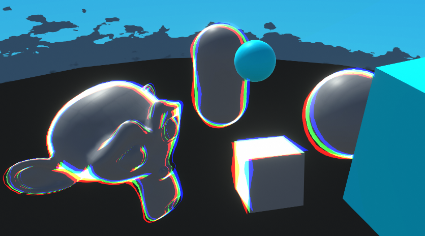
Goes through examples of Renderer Features and explains how to write Custom Renderer Features and Scriptable Render Passes for Universal RP
I need help with my shader.
The kyle robot is pink.
and the shader for robot2 is hidden/internalerrorshader
idk what to do


pls help
Is there a Material assigned under the SkinnedMeshRenderer component?

Oh I guess it's the Robot_Color one.

Can probably change the shader on the dropdown. I'm not sure why it's using the error one.
im trying to make a gorilla tag fan game, and the kyles robot was said to be the best model for it
how do i change the shader?

Probably want the Standard one
your problem can be potentially solved by going Edit->Rendering->Materials->Convert
could be the material just needs some encouragement to work in your enviroment
probably not the case then, ignore me 😁