#archived-shaders
1 messages · Page 42 of 1
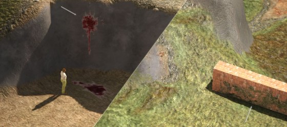
I have this scene in my unity

my character is a 3d model and ive set it to complete white
now I kind of want a environment which will have a texture on top of it like this

i want my camera to display first picture view, but the person will have this second picture thing masked on it as it walks like it will be present there but only visible on the person
can someone please help me with this?
Thanks in Advance!
If the camera is fixed like that, you can use screenspace shader
See detail texture in screenspace
https://docs.unity3d.com/Manual/SL-SurfaceShaderExamples.html

If the camera is movable, maybe you need to setup a camera with render texture
Set the sampler to point, in shader or in import settings.
Maybe try using tex2dlod to set the MIP level to 0 or something (might backfire).
Alpha cutoff is just that...a cutoff threshold. You're not going to get anti-aliasing or "non-rounding" from that, so you may need to edit the texture alpha to do what you want.
That's a Boolean Keyword https://docs.unity3d.com/Packages/com.unity.shadergraph@14.0/manual/Keywords.html#boolean-keywords
Could someone point me in the right direction, i'm trying to use UNITY_MATRIX_VP and other Unity shader variables like _ScreenParams in a compute shader but i'm not having much luck, there is no compile error but the values are all 0
I do have #include "UnityShaderVariables.cginc" in my compute shader but i'm wondering if there's something wrong with simply including it in a compute shader too?
Photoshop gradient tool ?
or with shader graf, or with hlsl
Photoshop / .NET paint / Gimp etc
If you however need a gradient with a very specific set of values, i'd simply create it in C# and save to asset or set as shader property as appropriate
Its ok i dont need it anymore
These values are not set for compute shaders because they are dependent on the current camera and render target settings, which compute shaders do not care about (unless you pass them in yourself)
To simplify a bit should #include "UnityCG.cginc" work just fine in a compute shader?
The choice of words around this particular difference between regular shader pipeline and compute shaders in unity is rather unnecessarily confusing imo so thanks for any help!
You can include that file, but the variables will just be defined, not assigned. Unity only assigns those globals for the regular shading pipeline, you'll have to do it yourself to access them in a compute shader.
That seems like a rather odd choice to not assign them if they're defined, considering one of the most common usecases for compute shaders is usually manipulating complex shapes or making custom rendering setups (the latter for me)
But atleast i know now, thanks!
Related thread with answer from Unity employee:
https://forum.unity.com/threads/global-shader-variables-in-compute-shaders.471211/

Unity Forum
Hi there,
I'm trying to access a global variable (set from C# with Shader.SetGlobal) from inside a Compute Shader.
Is there any reason this might not...
I would rather not get any random property conflicts in compute shaders from unity trying to assign it's default stuff
Like it was mentioned, those variables are set up by the engine at the moment of rendering.
For ex, UNITY_MATRIX_VP depends on the camera, and it will change during on frame for each rendered camera.
You might however be able to access them, depending how your are executing your compute shader : if you as using a generic dispatch, that is executed during the update loop, it will probably not work, but if you are dispatching the compute in one of the camera's command buffer, the values might still be there.
Hey, how can I evaluate the above texture at the below UV coorindates?

Input the bellow UV to the above ?
the above already has an input UV
I use it to animate it
so now I have the voronoi diagram moving "upwards". I however want the circles to come from the center in a sense
my first "hack" was that I just want to change the coorindate system
The voronoi node is not a texture, and juste generates data from the UV input. If you warp the UV input, you will also warp the "texture"
if x is seen as the angle and y is seen as the radius that would nearly do it (modulo some inconsistencies)
Polar coordinates node (rectangular to polar) ?
But it won't juste "move" the circles, it will fully distord the result
Hmm, nice node, good to know, but it doesn't do what I need
basically I want to have the output of the voronoi node, lets call it voronoi(x, y)
and then evaluate it at voronoi(arctan(x/y), sqrt(x^2 + y^2))
don't know if that makes sense
so I want to send x, y to their polar coordinates (phi, radius) and then evaluate the voronoi there
or is there maybe a much easier way to do what I want (have the balls all come from the center instead of from one side)
I'm dispatching in URP / HDRP by adding them to the RenderPipelineManager.beginCameraRendering, i ended up just supplying the matrix myself since the camera is available in the context, atleast it'll reliably work in both scene and game view then
Ah that's annoying, cus I know nothing about making shaders I was just following a tutorial about how to make a segmented health bar but they didn't use UI elements
Using polar coordinates and animating the radial value should be enough.
You can not re-evaluate a node with different UVs like you said, bur you can alter the original ones.
When using Fallback in a shader, should the fallback routine also use Unnamed passes?
Hmm it is going to be quite complicated like that
I think I am going to try to code the shader instead
Thank you!
Does anyone know how I can make a shader graph that realistically resembles wet mud (see reference pics)? Im already familiar to how shader graphs work, and Im doing this in HDRP, though I need some help


Should I just use a seamless texture instead?
Textures is probably the easiest. Otherwise you'd need yo work with some kind of noise textures probably to generate it, but that's quite hard
Alright
Basically just trying to find a way to USEPASS a shader pass that is not named - for some reason, every pass in a shader graph is named except Universal2D
Why does the texture on the object not change when I change tiling? The material changes but the object's texture remains the same. Does this have to do with uvs?


All the other settings on my shader do affect the object
Is the tiling settings connected to something ?
The whole project has an import preset I've made for point filter, so I know it's not that since the textures work just fine (same with the alpha) if I apply them to a mesh or other 3D object with a standard shader. It's the grass billboard shader used by the Terrain system in Unity that has some sort of anti-alias/bilinear filtering applied after the texture is brought in as a source.
The shader has point filtering for alpha (you can see that the "pixels" have round corners , they don't look squared), the issue is that it is using an opaque with alpha cutoff, and the linear filtering of the alpha gives this result.
It can be fixed by having a higher resolution texture, or lowering the cutout value
How would I lower the cutout value? I'm trying to keep a lowres aesthetic for the game so I'd like to avoid having to raise the resolution of textures unless it's absolutely necessary
I don't really see why the terrain grass / detail shader would overwrite the interpolation method set on the texture 🤔
What version of unity are you using ? Built in pipeline or URP / HDRP ?
is there any way to detect in a shader if a main light's ray has/would have passed through more than 2 faces?
it doesnt have to be very exact, a very rough approximation would be enough.
XY I am trying to mask out the area pictured where the body self shadows but the extended foot doesnt


I assume the answer is ray tracing, but that is nontrivial and costly(?)
Either
- raymarch in the volume with a SDF representation of the object to count the intersections
- do an "overlap count" buffer from the light point of view (custom passes / renderer features will help for this)
I have not heard of an overlap count before, how is that done? Would I be able to google resources for it?
It can be rendered in a single pass with a shader that draws back & front faces, with an additive blending : Output a constant 0.1 for example, and if the "ray" from one pixel goes through 4 faces, the rendered final value will be 0.4
Ooh okay, sort of like the depth buffer but its recording the depth between faces and not just from camera to first surface. That sounds do-able, thanks!
that looks cool
it should look like this
https://vimeo.com/manage/videos/816142031/privacy
when the person moves infront of screen
there are lots of ways to achieve this. if you are in a modern unity, use shader graph, and instead of using uv coordinates from the object (the default), use uv coordinates that correspond to the screen
i was doing shader earlier but that didnt work
think about what the UV node is doing in shader graph
but for shader graph i need to be in urp?
it is saying "for the given pixel on screen, query the mesh for what coordinate in the texture should i sample"
yes.
URP or HDRP
if you haven't gotten very far
you should probably switch to URP now
umm i havent done much with graphics
it will be much easier in shader graph
2021.3.21f1 and built in piepline
Ok, well clearly I don't see why it wouldn't use the interpolation setup of the texture :/
so the trick is the UV node. a pixel shader is about making decisions with what to draw pixel by pixel. so when it is deciding how to draw a pixel on your guy, it normally looks up a value on the mesh on that pixel (you can think of it as raycasting through the pixel onto the mesh)
but instead of using the value on the mesh
use some other uv coordinate. the uv coordinate is where on the texture to copy from
when it pastes onto the pixel it is trying to draw
you want the UV coordinate to be the same as the screen coordinate, instead of the coordinate from the mesh
@wicked prawn does that make sense?
Same, since every other material seems to just use the filtering method and interpolation of the original texture. Just this billboard grass shader seems to dislike point filter for some reason.
because that's like having a big rectangle across the screen, fit perfectly
okay well shader graph is fun
a lot of doing art in shaders is about UVs
it's very tricky
my manager showed me this same effect in 3d max today, he simply created 2 cameras one was looking at character (white material) and black background, one was looking at that texture kind of thing, and it was only being projected on the character
you can definitely achieve this with "compositing" and a lot of people do
compositing & masking
but doing unity stuff with multiple cameras
and messing around with the "z test" field in materials
it is buggy and gross
it isn't more esoteric than a UV, but you will have learned nothing lol
besides, making something in 3ds max... we call that "making a screenshot"
delivering a screenshot is easier than making it work in a game
yeah he was confusing me
i knew it isnt achievable simply like that in unity
I'll go with UV
glad someone answered i have to get these done tonight
okay here's what normally happens:
pixel shader(a screen position, mesh data) {
 i have a Texture
 i want to read the "right" pixel from the texture to draw on screen
 i ask mesh data
   mesh data.What position on the texture corresponds to the screen position on my mesh,
             given the way the camera is looking, what is in front of me, etc.)
 this is the uv coordinate sampled using the mesh
 query the texture at the uv coordinate. then return the color from the texture
}
and here is what you are trying to do:
 i have a Texture
 i want to read the "right" pixel from the texture to draw on screen
 i ask __SOMETHING ELSE__
   what position on the texture corresponds to the screen position i am drawing right now
   given the way that the camera is looking
   but also, i'm pretending that instead of a mesh, i'm using a big screen sized rectangle
   that is always pointing at the screen
 query the texture at the uv coordinate. then return the color from the texture
i guess what i would do is some arithmetic on the screen position directly
to get my uv coordinate
hmmm
oh i also need to set opacity for my 3d gameobject
4 levels, 100percent, 80percent, 60percent, 40percent
oh and one more thing, when my character will stop it should stop too
If I want my shaders to look a bit different (randomly, for example animation started at different offset), how do I go about that? Do I just make a field "offset" and sync that from the CPU?
Or is there a GPU-internal way to create random numbers like that
I am trying to impliment this pass now but I am not understanding how to do it, is this right?

Seems so
I cant find the option to render the pass to a texture, or make use of the pass
The pass must exist somewhere but I can't find any sort of output to make use of it
None of the provided renderer feature will do this, you will have to code your own
How would I do that? Or find tutorials to explain how to do that?
(small detail : the shader doesn't render depth at all, only "overlap")
Hey! Im having trouble with my game which only happens after building it it just spews out alot of shader errors I went in unity debugger and found these two errors
https://paste.ofcode.org/pHJg7zhmjFUBtxeSAd3HQD
I assume this is just refering to my semantics of calling it depth and not anything to do with the function?
Yes 😅
This page seems to have it all, I'll start implimenting this, thanks again
It will be more tricky than what is on this page, as you need to use the light's point of view
Yes, otherwise the material wouldnt change (as seen in the bottom right of the pics)
Im pretty sure it has to do with the uvs
but idk what to do with them
Indeed.
If the mesh has now UVs, the shader can't "guess" how to apply the texture.
You have to create UVs for this object, in a 3D modeling tool, or even with the probuilder package
welp that's gonna take a while
Does anyone know why the atan2 output looks like this (and doesn't seem to work for negeative x)?

I pretty much implemented the function as described in the unity docs here https://docs.unity3d.com/Packages/com.unity.shadergraph@5.9/manual/Polar-Coordinates-Node.html
copy and paste and then plot the angle component
void Unity_PolarCoordinates_float(float2 UV, out float2 Out)
{
    const float2 Center = float2(0.5, 0.5);
    const float twoPi = 2 * PI;
    float2 delta = UV - Center;
    float radius = length(delta);
    float angle = atan2(delta.x, delta.y) * 1.0/twoPi;
    Out = float2(radius, angle);
}

void WigglySphere_float(
    float2 uv,
    float3 sourceColor,
    out float3 color)
{
    float2 centred = uv - 0.5f;
    float2 polar;
    Unity_PolarCoordinates_float(uv, polar);

    color = polar.y;
}
ah
There are negative values, they just appear as black in previews. Unless you're clamping them with a saturate/max
Yes, but atan2 should handle negative values as far as I know?
It does, but the preview can't
Think of it : how would you display something darker than black ?
ah the angle is not normalized to 0-2pi but to -PI - +PI?
I get it
Thanks both of you!
yes makes sense thats how arctan is defined haha
Hey! Im having trouble with my game which only happens after building it it just spews out alot of shader errors I went in unity debugger and found these two errors
https://paste.ofcode.org/pHJg7zhmjFUBtxeSAd3HQD
And also a very noob question since I am new to shader programming: THere is no good way to get raw outputs etc for debugging right? I have to find some way to portray the result nicely as color so that I understand where the error is?
Yeah. The other option is to use a debugger like RenderDoc.
@hot yew, I made a shader graph and it seems to act in similar way
because im using a 3d gameobject?
you have to actually figure it out lol
i mean you gotta try to grok what UVs are
yeah
Hello everyone, this is my first shader with a custom node (and in general), I wanted to make a small fireball for a 2D game. The custom nodes basically output a texture of float1 with 0s and 1s where of the yellow and orange shapes

I wanted to ask if anyone knows any obvious easier way to do this or if I made any mistakes in this setup
also, would this scale to 100s or 1000s of projectiles with this shader?
Hello.
I'm trying to set up a simple shader graph that creates a grayscale gradient between two input values.
To remove banding I would like to use the Dither node.
I'm struggling to get this set up.
Has anyone done this or knows a place where I can look it up?
Thanks!
What part specifically are you getting stuck on? What did you try already?
I am trying to turn off culling on a custom shader so that a player cape can be seen from both sides.
following the advice of this post (and the rest of the thread) https://forum.unity.com/threads/how-to-turn-off-back-face-culling.329744/#post-3182708,
i created a new custom shader by right-clicking in assets, and then added Cull Off to the subshader section, and to the pass section within the subshader section.
when i selected it as the shader for my material however, it did not change anything.
I'm hitting a road block here (First time messing around in HLSL too).
I'm trying to write a new shader for RW since none of the current ones do what I want. I need to implement the base stuff that those ones already do though as well.
I'm getting caught up on the vertex shader bit atm. I need the base of the texture with said applied shader to essentially not move at all and the top most part of the texture should move the most. Think of a plant in real life, where the wind blows it back and forth and up and down but the trunk, base, roots, etc don't move. Video showing what it looks like now and current vertex shader below. (using hardcoded values for testing purposes)
            // vertex shader function, input vertex format as an argument
            v2f vert (appdata v)
            {
                v2f o;
                o.vertex = UnityObjectToClipPos(v.vertex); // transformed vertex position

                // calculate height of current vertex
                float height = (v.vertex.y + 1) / 2;

                // calculate sway strength based on height
                float swayStrength = 1 - height;

                // calculate sway frequency and direction
                float swayFrequency = 2 * 0.25; // 2 * _SwayHead;
                float3 swayDirection = float3(0, 1, 0);
                if (height > 0.1)
                {
                    swayDirection.xy = cos((1 - height) * 3.14 / 2);
                }

                // calculate sway offset based on height and wind speed
                float3 worldPos = mul(unity_ObjectToWorld, v.vertex).xyz;
                float windStrength = pow(clamp(1.75, 0, 1), 2); // pow(clamp(_WindSpeed, 0, 1), 2)
                float3 swayOffset = float3(0, 0, 0);
                if (height > 0.1)
                {
                    swayOffset = sin(worldPos * swayFrequency + _Time.y) * swayDirection * windStrength * swayStrength;
                    swayOffset.xy *= height;
                }

                o.vertex.xy += swayOffset;

                o.uv = TRANSFORM_TEX(v.uv * _MainTex_ST.xy + _MainTex_ST.zw, _MainTex);
                return o;
            }
Edit:not this channel
Please don't cross-post.
I'm guessing there that you really don't want to modify the vertex after it has been transformed to clip space, which is what you're doing.
What you want to do, I think, is transform it to world space, modify it according to wind direction, and then transform it world-space==>clip-space.
That macro that you used at the start is an expedient way to transform an object-space point directly to clip-space, hiding the intermediate stage of view/world-space.
ANOTHER way to do it is transform your wind direction to object space somehow, then you can "just" apply that to the model (if it is unscaled) and then use the UnityObjectToClipPos() macro.
Now to find the code to do that (the first way using world space)...
worldSpacePos=mul(unity_ObjectToWorld, objSpacePos)Takes an object space point and transforms it to world space. This includes translate, rotation, scale of the object. The info you see in the inspector of the game object, relative to world space.
Now that you've done that, your vert is in world space positioned correctly, "in the world". But the camera may be looking anywhere, and further, the camera's 3D space (if the object is even in it) has to be "flattened" into the 2D screen with perspective applied.
So we first rotate the world to correspond to the camera! Think of you standing still and the world rotating under you, until it is position like the camera's view. Yeah, it's backwards from what you'd think. So we transform the world space points to view space...that's the camera's view. Still in 3D.
viewSpacePos=mul(UNITY_MATRIX_V, worldSpacePos);
Now that we have view space, we can "splat" that onto the 2D screen, with perspective applied such that the things farther away are "squished" toward the center of the screen giving us the "cone" shaped view frustum. This is something we set up for the next shader stage but we don't really apply it yet....so we need a special space called "clip space" that is a LOGICAL representation of the screen that clips to the view-frustum (it ranges from -1 to +1 in all three axis directions AFTER the perspective divide is done during rasterization...called NDC space...anything outside of that gets "clipped" hence the name). The GPU actually does that math for us later during rasterization. It does the "perspective divide" and divides the xyz values of a clip-space position by the .w "depth" of the point in the view frustum to squish it and give us the proper 3D perspective, unless we have an orthogonal camera setup, but we'll ignore that for now and assume 3D perspective.
clipSpacePos=mul(UNITY_MATRIX_P, viewSpacePos);
The Vert shader ALWAYS outputs clip space, it's a requirement of the stage, basically.
Well well well, this is a lot to take in. 😄
It'll probably take me a full weekend to really understand everything you've said and put it into practice. But I think I get the gist of it, for now.
I unfortunately do need to get some rest before I go climbing tomorrow so I'll have another stab at this after that tomorrow.
And there's cheater-combos of those matrix transforms. For example, there's UNITY_MATRIX_VP to apply both the View and the Projection matrix at the same time.
https://docs.unity3d.com/Manual/SL-UnityShaderVariables.html
But you get the idea, anyway. You have to decide where and when to apply your changes so that you get the object translation, rotation, and scale, apply the changes according to the scaled Y height in world space, and then complete the rest of the process to get to clip space that you have to output from the vert() stage.
Enjoy your climbing.
Sounds good, thank you so much by the way!!
Folks, question:
I have this shader, from a package called flatkit, that looks normal on the editor, but on a platform build (PS5), it doesn't show... I had this same behavior on PS4 but fixed it by setting
#pragma target 4.5
But this one isn't working... anyone has a clue on why this might be?


nvm fixed it 😄
do motion vectors just not work for single pass instanced xr? im sampling _CameraMotionVectorsTexture like i would any screen space texture but it seems like only the left eye slice has anything written into it
UNITY_DECLARE_SCREENSPACE_TEXTURE(_CameraMotionVectorsTexture);

fixed4 frag (v2f_img i) : SV_Target
{
    UNITY_SETUP_STEREO_EYE_INDEX_POST_VERTEX(i);
    return UNITY_SAMPLE_SCREENSPACE_TEXTURE(_CameraMotionVectorsTexture);
}
Hi all, I'm new to shaders and trying to show a 2D image on a plane with some effects:
- First of all, I need the transparent parts of the image to stay transparent
- Second of all, I want a little cutout to where the player is
I achieved the first effect by just using the Unlit/Transparent Cutout shader. For the second effect I followed a cutout tutorial, and can now render a hole in the object based on the screenspace to show the player. However...
How do I combine these effects?
Logically I have two alpha channels, one from the image and one from the player cutout, so I need to combine them. I tried subtracting the player cutout from the original image's alpha, but that only works for the main image and not the transparent edges... Any help would be very much welcome!
Images for context:
First image looks good!
Second image doesn't...
Third is the current ShaderGraph


To combine the alpha masks, use a multiply or minimum node
What are the "transaprent edges" you are talking about ?
Normally, the edges of the image are transparent. However, when applying the subtraction node they turn white. I'll try the nodes you recommended, thanks
Ah yes.
Well, when you used the subtraction node, it resulted in negative alpha values, doing unexpected blending.
You could as well add a saturate node after the sub node
That worked perfectly! Thanks!
What part specifically are you getting
anyone know why the time value of this shader graph is not showing in scene view? (It moves how I want it to in the graph editor but whenever I play the effect and yes it has been connected, it doesnt move with the motion in the graph)

btw im in hdrp
Well, I'm guessing here. But since you're using single-pass instancing, there's only one texture, and it is the one for the left eye.
So you'll have to compute the right eye's perspective 'manually' like you compute the right eye manually. (single pass outputs both eyes in one pass, right? Gives you two inputs, camera view data for each eye, writes MRT).
As to how to do that, IDK, I don't do xr.
Did you enable "animated materials" in the scene view settings (top) ?
ooooh thanks for telling me, it turns out i need to select "always refresh" as animated materials is not a setting in hdrp i think
all good now ty
can i make an exposed slider from shader graph?
I think there's a checkbox for that when you select a property? maybe range?
oh yea, thanks!

How do you write shaders(with code) in the unity hdrp?
Use shadergraph and custom function nodes
so it s not possible?
Not impossible, but very hard
It's way easier to user shadergraph as the "holder" of your code, managing all the complex boilerplate code, and encapsulate your code in one or multiple hlsl files, references in custom function nodes

Hover the ! icon to show the issue
Bu basically, you didn't write the code as expected
Shadergraph will generate itself the function bloc, you need to only write the content
And it doesn't return anything, it's a void function, you need to set the output values
in your case OUTMAIN = 1-inputColor;
Does anyone know any good page explaining what "Override Property Declaration" actually does? I can't find anything, neither in the official unity docs nor outside
Also, do I understand this right https://blog.unity.com/engine-platform/srp-batcher-speed-up-your-rendering
this right? I should not have the same material on many different objects where I change its properties (like color) for each of these objects?

alr that makes sense, so the function will create a struct, and inside the function I have to set the values to it, but I do not have to refference the struct
Is that correct?
No struct, it it as function with output parameters
Here is a very nice barebones tutorial: https://www.vertexfragment.com/ramblings/unity-custom-shader-graph/
Overview Custom Shader Graph Node Function Setup Function Implementation Creating the Custom Node Using the Custom Node References Overview The Unity Shader Graph is a powerful tool that provides the ability to design custom shaders and effects without having to write any code. It comes with a well-rounded suite of existing nodes and util...
This helped me to get setup yesterday
Taking your example again, it would be something like :
void InverseColor (float4 inputColor, out float4 OUTMAIN){....}
okay seems logical
Yes : changing the color = changing the material
but it is just an input to a shader? I always thought this should be cheap? All that would need to be updated is to send 3 or 4 floats to the GPU no?
the shader stays the same, all the "data intensive inputs" like meshes or textures stay the same, I only change the smallest input
I don't have deep knowledge in this, but afaik the input for a shader are send as a whole, you need to change "everything" when switching the setup, not only the color.
With the exception of the constant buffers, that allow to store all the data for a single batch containing multiple materials, and uses pointers instead.
Oh ok, do you know the keywords that I should search for to understand these topics more deeply?
Like what of this is just GPUs, what is bad design of unity, and how is unity designed etc
Look for the different overrides names
@nova needle@amber saffron
Using PropertyBlocks would be the best way to do this, right?
This way dynamic batching can still work on the objects
I actually still get the same error with the rewritten funciton


I have no clue haha, this is the kind of stuff I want to understand
When using the string mode it just needs the body of the function, not the entire declaration. So just InvertedColor = Color; here.
More info in docs https://docs.unity3d.com/Packages/com.unity.shadergraph@14.0/manual/Custom-Function-Node.html
bruh thanks
If I have an x offset in tiling an offset of -0.5, and plug that into SimpleNoise, why isn't, what was before at the right border (with offset 0) now in the middle?
Or to ask differently, what are the dimensions of the simple noise?
Can kinda ignore it. You always want to use the Exposed tickbox instead to define if a property should be Per-Material (set via material inspector or material.SetX functions) or Global (set via Shader.SetGlobalX functions).
The only exception, is a Matrix4x4 property, as they are always defined Per-Material by default, but cannot be exposed on the material. If you need to set a global matrix, you'd need to use the Override Property Declaration to force it to Global, or it'll lead to glitchy/garbage values.
You can also use it to intentionally break the SRP Batcher compatibility for the shader, (e.g. define an exposed property as "global" - which really just moves it out of the PerMaterial cbuffer - or vice versa)
It can also be used to switch properties to Instanced for the DOTS Hybrid Renderer too, but I don't know anything about that.
You'd want to avoid MaterialPropertyBlocks in URP/HDRP as it breaks SRP Batcher compatibility for those renderers. Using material instances is better.
(I also think MPBs will still break dynamic batching. Unless you're using GPU Instancing too)
Yeah, I am doing DOTS, thats why I care for that property unfortunately haha
the tutorials tell me to tick it
I assume DOTs probably isn't relying on the SRP batcher anyway, so using the override property declaration to switch the properties to Instanced is probably required. But idk
Yeah, I would just really like to understand this rendering stuff, at least at a high level
Maybe due to the Scale set in the noise node?
But I don't know where to start
On the link there is syntax supplied how to define the funciton inside a file, but it gives me following error
#ifndef MYHLSLINCLUDE_INCLUDED
#define MYHLSLINCLUDE_INCLUDED

float InvertColor(float Color)
{
    return 1.0 - Color;
}
#endif //MYHLSLINCLUDE_INCLUDED
Maybe you know why

You need to add the precision suffix, probably _float here. So the name of the function would be InvertColor_float in the file, and InvertColor in the name field on the node. The docs also explain this
Functions should also be void and have out parameters, as I think Remy already explained earlier
yes sorry I forgot to update that but, how comes the function always needs to have _float as a suffix?
It can be _half too, it depends on the Precision the node has been set to. Also see https://docs.unity3d.com/Packages/com.unity.shadergraph@14.0/manual/Precision-Modes.html
You can also have both, the node can be set to "inherit" the precision of it's inputs. Hence the suffix is required
thanks for the great explanations, really makes sense
I do not think that is it, or does the editor behave differently in shader graph and real life? No offset (mark the black little thing in the lower left corner):

And now with -0.5 offset:

see how it moved exactly half, scale is at 8 though
but if I do a very similar experiment in game, this behaves differently
wait what are the UV coordinates of the default Plane mesh?
Hmm weird, should be the same in scene/game too.
iirc, the default plane mesh has regular 0 to 1 uvs
I think they're 0-1, same as the quad here
But what do you mean by "very similar experiment in game" ?
The offset value is not exposed as a property here
Its not exposed because I deleted the exposure for the pictures
normally it is
Basically I have something like a parallax background, but at 0 distance, so it should just move exactly as quickly as the player (basically I have a static mesh that moves with the player and just want to change its offset so that it displays the right background)
If thats really dumb please tell me haha
And I am trying to get the background to move at the right speed, which in my thought should be
-PlayerPosition / SizeOfBackgroundInWorldCoordinates
yeah ok the uvs are indeed 1-10. I just thought that might be it because I was surprised that the plane itself has measurements 10x10, that cost me a few hours to notice today already haha
Ok but seems to work now lol, no idea what I changed
Ok, I think I found out how I should have been doing this
How do I manage to get the UVs in world coordinates?
So I want the UVs of my mesh to be their world coordinate position
Don't use UVs, use the world position
Would be the Position node (world space), may need to Swizzle depending on which axis the plane is aligned to. Then put into the UV port on the noise/tiling and offset
does sampler state work in webgl?
how would you go about reading the world space normals inside a hdrp shadergraph so they can be read as a vector3?

new to shaders, trying to make water shader but it doesnt apply, im using URP, created shader and then material out of it.

does it stay purple if you delete the link to Base Color?
so that it's just a constant color input
all time purple
scroll up in the graph inspector and look at the list of targets
I do see Universal in there

if you create a new URP lit shader graph, is the preview also purple?

i imported the package from the manager
do i need to do more to make it work?

changing "Shader" does nothing
The magenta error shader likely means you haven't configured your project to use URP correctly. Check the pipeline asset is assigned under Project Settings (see urp docs pinned in #archived-urp for more info)
I'm having an issue with shaders not consistently working in my unity project. Here is an example of a shader that flickers on and off. The view is Scene view but the issue persists in game view. This issue is not solely occurring with screen edge but it is easier to show off the issue with screen edge. Is it possible my project isn't setup correctly?


The position variable is from an Object node's position
Well, get rid of the "random range" stuff, and base a TEST solely off of the 2D position and see if it still flickers....
And make sure the position is world-space, not some other space.
I'm not sure if this is the right place to ask but I'm trying to make a model and export it using an addon named Vrm but it gives me this error and when I export it the model's material looks wrong
VRM is an external system with its own workflows and quirks so it's unlikely anyone here knows
The warning implies that the material's shader is not what's expected by the system
Oh, well thanks anyways!
so i guess a fullscreen shader is always on top, then whats the best way to make a background, custom skybox or just a big quad behind/under everything facing the camera or something else? (just need something behind the board, the camera will not move or rotate and i want the background to feel 2D so if it was a quad it would face the camera)

well yes when applying a post process effect its gonna be on top of the entire screen. But that doesn't mean that you can't make your effect appear behind objects. You could check for the depth and with that render your pattern behind everything. But of course you can also use the skybox or just simply place a quad behind everything
Thanks! For now i will stick to a quad, but gonna check and learn about postprocessing!
Post processing usually uses a quad or an oversized triangle. Like @lunar valley said/implied skybox shader is like a post process, but it's a mid process....between opaque and transparent queues. Checks the depth buffer.
Their suggestion of a skybox shader is a good one, IMO. It's all part-and-parcel.
is there a way unity lets you,
1.Allocate the MeshDataArray on the gpu
2. Get a native Ptr to that and then edit it in a computeshader?
Removing Random.Range did not fix the flickering issue, and Object node does not have options for world space. I'm trying to randomly assign hue variance to my trees based off of each object's position. If you can think of a different node for object position let me know.

What kind of objects are the trees? I'm thinking they might be batched in some way which can alter object position
Yeah if they are sprites that's probably the case. Might be better to tint based on Vertex Color instead (or at least as the seed for the random number gen)
The trees are prefabs with a child object sprite renderer in which the shader is applied.
Can you explain how vertex color would be applied? I've never used it before and it seems to be more of a 3d thing.
does someone know how you can make a mesh that runs completely on the gpu?
like I would like to
Reserve some storage on the Gpu,
then start a Compute Shader and write to it.
I don't do much 2D but my understanding is that the Color field on the Sprite Renderer component is sent into the shader through vertex colours in the sprite mesh (though same colour for all vertices). Could get it in Shader Graph using the Vertex Color node.
Though I'm not sure if the sprite graph types are already applying that colour
Anyone know how to get baked lighting to work with Shader Graph shaders, which my projects is heavily dependent on?
Is there anyone who knows how to work in a outline shader for 2D post processing?
I’m trying different YT tutorials but most of them are for 3D, and I’m working with a 2D game.
I am in dire need of help to create a separate post processing camera, and blend that with the main camera so that I can have different layers for outline objects.
I did try a material shader, but since it requires two passes it can not be batched, so that’s why I started looking into a post process alternative.
I recently tried the YT tutorial called: “creating an outline effect as a post process in unity” and afaik this should work with the build in render pipeline which I use, but is aimed at 3D.
If anyone could help me adjust it for 2D it would be lovely!
Here is an example made with HDRP:
https://github.com/alelievr/HDRP-Custom-Passes#outline-effect
Dunno about good implementations for other pipelines. The code is available in this repository, so you can check it out and tweak for your needs.
Ok, I’ll check it out 👍
Hey guys, if I wanted to make a BIRP shader that turns everything into pixel art, where would I start? Is that possible in BIRP?
I've done a couple shaders so far but nothing really like this.
Well jeez there is an asset just for this haha "Pixelation"
i have been at this for about 20 hours over the past few days, not just for pixelation but for any shader i'd make, i know you can do it with a custom render feature but as a beginner i really have no interest in trying to learn that alongside c#. i'm trying to see if theres a way to overlay it on your camera or something similar to that and man it is a pain
So, I've simplified the shader I was using (it works as intended), and now I've imported it into a brand new project to see if I can isolate the shader flickering issue. But, now my shader isn't working as intended. It defaults to a position of (0,0) for every object.
The objects with this material/shader are objects with a sprite renderer on them, and nothing else.
Any help identifying why the Object node is outputting a position of (0,0) (red) regardless of the objects position?


Highly recommend the shader I mentioned, at least for this. Maybe you can look at it and get an idea of what it's doing, because it is just that -- a camera overlay.

Toon shading is from another shader.
i checked it out and apparently i had it downloaded so i'll give it a look again tomorrow, thanks for the advice, good luck with your stuff
Thanks you as well
why not just simply add outline to the images? using image editor
That's why we test, so we eliminate things. So good, and what @grizzled bolt and @regal stag said about batching makes sense.
But to answer one of your other questions, you don't use the object node you use the position node:
https://docs.unity3d.com/Packages/com.unity.shadergraph@7.1/manual/Position-Node.html
Still, static batching will mess that up. As stated above. So you'd want instancing rather than batching, I assume. But URP batcher works differently than BiRP batching, so I'm not sure what you get (I think instancing)...and if you based it off world position with instancing happening, it might work. Or you could create, say, 50 material variants and assign them to object instances based on world pos in C#, then no shader magic is even required, and SRP would batch them up.
Position node makes the shader useless. I'm assuming its because each sprite renderer is a child of a prefab object and therefore in the same local location. Regardless, the result is that every object is the same color. The object node seems to provide a more accurate world-object position.
edit - Actually I have no idea what position node does, but it does break the shader. No matter what gradient I use the shader is unapplied to the trees, so i assume its breaking my shadergraph.
Having multiple materials is pointless as I'm trying to make a single prefab have variations. Unless, theres a way to have the materials randomly selected.
I know next to nothing about batching, so you lost me on that part.
I'll be honest, at this point i'm thinking of giving up on shadergraph. I've always tried to use them through lots of different tutorials for the simplest thing, but they've always broken in some way. It just seems like a broken feature in unity, and yet i see lots of people using them in their games.
I would try multiple materials, but have a C# script assign a random one out of a list at runtime. Should be able to ask in a scripting channel if you're unsure how to do that. But be careful, as different materials means those sprites no longer batch and increases draw calls. It may hurt performance if you use too many materials.
Afaik the "Color" field on the sprite renderer should also already apply a tint to the whole sprite? You could randomise that a little through the script too.
The color field doesn't quite do what I want as that will just apply a color on top. I was using shaders because of their "blend" node. That applies colors in a much more appealing way.
But, I appreciate the help.
Hey ya'll first post in this channel. I'm having an issue where my game objects using a shader are invisible. When I fidget with the settings in the inspector(see video) my game object will suddenly appear. The really weird thing is this will sometimes be a fix for an hour or so. I found this which could potentially be referencing the same issue but I can't follow the context. https://issuetracker.unity3d.com/issues/urp-gameobject-shader-is-invisible-in-scene-slash-game-view-until-shader-property-panel-window-is-expanded
Reproduction steps: 1. Create a new URP project 2. Import the provided custom package "UrpTree.unitypackage" 3. In the Project windo...
Because there are 2D sprite sheet animations for X amount of characters and enemies and that would take too much time! ( plus i want to be able to change color of the outline during runtime )
In HLSL is there any way to access a texture as if it was a regular array of color/float4?
textureObject.Load
Before SRP times: When would I not want to use GPU instancing on a given property of a material?
Lets say I have a color property in my shader
If I do not add the property to UNITY_INSTANCING_BUFFER, then, if I understand correctly, if I change the color two blue for one of my objects and red for the other one, then unity would now upload two different materials to the GPU, one blue and one red (say they have id 0 and 1), and afterwards always say: Draw this object with this mesh and material 0, this object with same mesh but material 1
Whereas if I instance it, then the color would needed to be uploaded every frame, right? So I only want to instance properties that change frequently or where I have so many different values that I do not want to have a single material for all of them in the persistent GPU memory
Do I understand this right?
The default batcher isn't smart enough to recognize when only instanced properties are different between materials and combines those into instanced draws. To change instanced properties, you have to use MaterialPropertyBlock through script. That way, the same material is used, but instanced properties are overridden on each renderer.
So there's no benefit in making your properties instanced unless you also use MaterialPropertyBlock to set them.
@low lichen Ok, thank you! But my general understanding is right? So the non-instances properties of a material are just in persistent GPU memory all the time, so the reason not just instance everything (+ use MaterialPropertyBlock) is because you want the other variables to be fixed and not updated every frame?
In every case, the material properties are always reuploaded before the draw call, in the built-in renderer anyway. That's what SRP Batcher optimizes, by keeping the material data persistent on the GPU.
Even the mesh?
No, the mesh is not part of the material
As in, does the default renderer even reupload the meshes every call?
Ok
So meshes have always been persistent, since obviously they are quite large
And now the SRP batcher came along and thought maybe we should also persist other stuff?
But somehow then the tutorials on GPU instancing say that the SRP renderer does not work with GPU instancing at all anymore
thanks by the way for answering all these noob questions! haha
That's true, SRP Batcher is not compatible with GPU instancing.
But couldn't they have done something in between? Like vs Original: Upload everything every frame and now: upload only once?
The straight way forward would have been to make the non-instanced properties persistent and then reupload the instanced ones?
It just seems like a huge step backwards to me like this haha
I think they decided to prioritize optimizing the draw call performance of unchanging materials, since that's 99% of draw calls in most games.
And it makes it more user friendly, since you don't have to worry as much about the number of materials in your scene, or use workarounds like MaterialPropertyBlock.
Also, GPU instancing is more limited. It can only batch the same mesh. For cases where you still want to use GPU instancing, you can use it manually with Graphics.DrawMeshInstanced.
So, the story is like this:
- Totally unoptimized: Upload every mesh, all material properties (transform, scale, color, custom properties) every frame, for every object
- Old Renderer: Make meshes persistent, but upload all material properties every frame (This is where the old renderer was) for every object
- Old Renderer + GPU Instancing: Make meshes persistent, but notice than many object will have mostly the same material properties, so only use one draw call for them (where you send the properties, and for the instanced properties you just send a list or something)
- SRP: Make meshes and Materials properties persistent, and basically just drawCall(MeshID, MaterialID,) - but some properties still have to be instanced here too (at least position etc) - Why don't they give us the allowance to add our own instanced properties
is there any post processing shader expert that could help with a 2d outline effect that can be used with a camera for selected layers and output to a render texture and combined with the main camera? (NOTE, 2D only)
trying to layer a texture img on top of a gradient I created, but for some reason it's whitening the texture img a lot- any ideas as to why?

Dont use add to layer colors else you will just lighten them (add the numerical values).
To layer, use the lerp node with:
a: bottom
b: top (rgb of your texture)
t: top opacity (a of your texture)
IT WORKS, THANK YOU
Does anyone know why this might be happening?

These are all just quad meshes that render the texture in transparent mode. Their z coordinate is set to equal their y coordinate
so it should be clear for the camera which one has to go in front or not? Since the one with lower z coordinate are closer
Camera doesn't check for the z position in 2D, but instead their sprite depths
change the sprite depth based on the y coord
@keen cloud I don't think I am using a 2D Camera. I am using a normal 3D project (I am doing this hack since DOTS doesn't support 2D yet)
so these are really all just planes that render a small texture
interesting
how far away is the camera?
because it could be zdepth overlapping
if it's far away, the difference becomes too small
It is a orthographic camera (cinemachine), located at 0, 0, -20
what I did change is that the far clipping plane is at 1 000 000 or so
so that I can freely change the z values without worrying things go out of sight
yea that will most definetelly be the issue
change it to something sane like 100
and just map the z values to a max of 100
or even a 1000 is just fine
Unforuntately not, the issue persists
hmm
they are planes? not sprites?


Yeah this is how the prefab looks

and you are sure that the Z changes?
because you are using the Sprite Shader
sprite shader ignores zdepth
I am using a standard unlit shader created by the shader graph @keen cloud

I just called it SpriteShader
But I think it should not ignore anything
Transparent surface mode would mean it doesn't write to the depth buffer by default. You likely want Opaque surface mode but enable Alpha Clipping instead.
Aha!
@regal stag majestic save, thank you!
@keen cloud also thanks for all the help! 🙂
I'm trying to make a pixelization shader

does anyone know what the logic behind getting clean object edges would be?
I don't want it to look antialiased
like this for example
also by observing the UV, I noticed this happening

sorry, missclick
ah, well first, yes, wrong place to ask, I feel like this is more a thing for #⛰️┃terrain-3d
secondly, yes you could use raymarching to blend these two meshes, idk how to implement it in the best way possible tho
oh okay, thanks I will move my message so.
Maybe you have to activate Windows... 😉
funny

Does anyone know why this animation is really laggy in the editor window?
I just want the ghost to move up and down slowly while moving
By default the Scene View does not constantly re-render the scene to help with editor performance. But there's a dropdown at the top right, enable "Always Refresh"

I guess it should not be that laggy?

Thank you!
also, is there some sane way to get an object into the right kind of orientation when exporting from blender to unity?
I usually use these settings

If that doesn't work, I imagine other channels can help further with that
Hey guys ^^
Would there be an easy way to add a shader effect to all of your shaders? (not post processing). What I want to do is Tonemapping but during the forward pass and not as a postprocess
thanks again!
is this the right place to ask about shadergraph?
There's no easy way to add an effect to all shaders, would need to rewrite them manually. Would need to calculate the final shaded value, then apply the tonemapping to it.
Probably why post process is usually the method used for stuff like Tonemapping. (But if you're targeting mobile/VR I guess it makes sense to avoid fullscreen passes)
yuppp, VR
I'll just write a shaderinc and copy pasta it everywhere lol
most of my shaders are written in HLSL so thank god for that lol
I'm also not sure if applying the tonemapping before will work exactly the same with transparent objects. Might blend differently
One more question. Most of my animations will be really simple (like just a bit of hopping from left to right for "walking" while moving in the direction). I want to do all of this completly in-shader and either just have different shaders or one shader with flags for walking, idle etc.
Is this
- The preferred / best practice way to do it?
- for some reason a bad way to do it?
I am asking since the normally you could animate this on the CPU with the tools and then it would just animate the specific properties. But I don't know if this is done for convenience or because my idea is bad for some reason
Yes, you can ask shadergraph related questions here
Am I doing something wrong? For some reason my preview isn't working. I'm on 2021.3.23f1

I think most high quality Quest 2 games are doing some type of forward pass Tonemapping from what I've seen so I'll just have to live with it lol
Hey im sorry for asking a really noobish question as its my first time learning about shaders. Unity uses HLSL for its shaders right? But i thought it was for Directx only not metal or vulkan so how does this shader language work on Linux,mac and Windows
Probably not the usual way to handle animations but should be okay? Be aware that changing vertices on the GPU means :
- does not automatically recalculate normals (so if you do any rotations, would need to calculate those too, if shading is important)
- does not update colliders, so physics system won't act to any changes in vertex positions
- does not update renderer bounds. If the camera goes outside the original bounds, the renderer will be culled. So try not to offset vertices too far.
If you're looking to avoid CPU animations to be able to animate lots of meshes, and want more complicated animations than a sine movement, you may want to look into "Vertex Animation Textures". The idea there is to bake the animation (vertex positions, normals, etc) to a texture, then read that in the vertex shader.
Unity pre-processes the hlsl shaders and will cross compile them to languages compatibles for all platforms
Thanks, that helps a lot! Yeah I am talking about small graphics effects mostly
so the first few points are all fine
ahh i see remy thank u so much thats what i figured have a good day
we love unity cuz it does the hard work 
does anyone know what's wrong?
Only the preview, or is the shader also not working when applied to an object ?
ill try putting it on an object and see what happens
it works when I put it on an object
only the preview is not working
🤷♂️
Id try to close and open the preview window, change the preview mesh and close and open the whole shader graph window, its most likely a bug and it might reset to normal by doing something like that
when I changed it from opaque to transparent it started working
Weird. But it should work in Opaque too. Just using transparent will lead to other problems (like sorting issues).
If it doesn't work with opaque for some reason, could just preview the material in Scene View / Game View instead.
I think it just needed something changed to recompile
Hey so I just watched a really nice tutorial on how to create trees in blender, where they basically just make a path and then use a skin modifier.
Could one also do something like that on a GPU?
Or say on the CPU create the tree as a very simple tree (graph), just the as path
and then the GPU just makes this a mesh with something like a skin modifier etc? That would make procedual generation of these meshes really easy
Is it ok to post a link to a YT tutorial I want to refer to?
I have a question regarding the tutorials implementation of a post process effect it does.
Alright, here goes nothing:
This YouTube video shows a tutorial on how to add a post process effect (outline) to your 3D project.
Now to the question:
I am wondering if this implementation would work for a 2D project?
Or can it be adapted to work on a 2D project, and if so, how?

Outlines can be tricky to do in a mesh shader. So, let's do it in post instead...
Want to support the channel?
▶️ Help fund new episodes by joining the Patreon - http://www.patreon.com/GameDevGuide
🛒Get GameDevGuide Merch! - http://www.gamedevguide.store
💡 Get O...
yes, you can create a tree inside of unity only using a shader. With a geometry shader for example you have the possiblity to add vertecies inside of a shader.
But I thought geometry shaders are kind of outdated since so expensive?
So probably doing this is then quite expensive?
Does anyonw know what the simplest way is to make the noise function periodic in shader graph?
yes geomtry shaders can be quite expensive, but instead of that you can pretty much always substitude it with a compute shader, which is probably most performant
does anyone know why it does not allow me to output the RGB of this combine to the vertex position?

(I know I should add the positions first, but it also doesn't work then - I guess there is some data type thats wrong, maybe the texture somehow has the wrong format?)
Sample Texture 2D cannot be used in vertex stage, but Sample Texture 2DLOD can be
Thanks!
so when I try to Lerp a texture with a sample gradient node it doesnt work
it does work with a makeshift gradient but...
what are you trying to achieve?
question, could you use urp's camera stacking and have a camera be looking at a quad that has a shader that gives a psx pixelate effect and have that overlay on the main camera with camera stacking, it works with dithering but i wonder if it's possible to do it with effects like i described. take this image for example, everything behind the glass appears fuzzy and distorted

if I have understood your question correctly, then yeah, sure
yea i'm not the best at wording stuff, but thanks, i'm hoping it's true cause this method is a lot easier than others i've seen
add a texture on top of a gradient, like this:

and what is the problem? cause it seams you managed to achieve what you wanted?
How would I achieve what they said in this video about culling the cards


In this 2021 GDC session, miHoYo CEO Haoyu Cai shares ideas behind the making of Genshin Impact, including the game’s anime style, character/stage design, pipeline, and more.
Register for GDC 2022, in-person in San Francisco, March 21-25, 2022: https://gdconf.com/passes-prices/?_mc=blog_x_gdcsfr_un_x_gdcsf_x_x-1
Join the GDC mailing list: http...
24:15
The problem is that adding whitens the textures; earlier I posted asking for help and someone said to use the Lerp, which does work for some things but not with the sample gradient node
well my guess is that sample gradient gives you a color but lerp interpolates between two things using a scalar which ranges between 0 and 1. not a color(4 values)
So is there another node I should use or a way to convert sample gradient to be compatible?
Really my goal is to be able to dynamically make gradients I can slap textures on top of
maybe you can calculate the luminance of the color and plug that into the t value of the lerp
tbh. now that I think about it just calculating the luminance wouldn't work because the could be the same, instead you might need a second gradient ranging from black to white and use that for t instead
If the textures contain an alpha channel, you'd typically use the A output of the texture sample as the T of the Lerp.
A input would be the sample gradient result
B input as RGBA of texture (or another Vector4/colour)
ups pinged wrong guy
do the dot product between the card normal and the viewDirection if negative cull the vertex

like so correct?
yeah
but tbh. shadergraf should have an option for backface culling so you shouldn't need to do it yourself
I could be missing something (maybe this doesn't work for you?), but shader graph does cull backfaces by default:

Yeah but that'd just end up only rendering one side or behind. Just trying to smooth the face when the camera is facing the tree
- you pinged the wrong guy 2. I know
I do not know what smooth the face is supposed to mean
Like such in the video, any vertex normal facing the camera, it'll clip the normal resulting in a more smooth look
I got it though, thanks anyway
ok i guess...

Anyone know why I'm getting this error: "Type mismatch between conditional values"?
The custom function is displayed in the bottom left
Out = (Bool) ? A : B
My best guess is that in 2020.3 's custom function doesn't support gradient, but I just want to be sure.
Seems like the ternary operator doesn't work on struct types.

I used the same ternary operator but had it output floats instead
error: "unexpected token '}'"
I think that's because you're missing a ; at the end of the line
That fixed it for the float comparison. The gradient one is still off. I'll look into another logic route then. Thanks for the help
It's uh, quite hacky, but this seems to work
if (Bool)
Out = A;
else
Out = B;
}
bool isfinite(Gradient g) {
   return true;
The isfinite part is another bug workaround. Seems it really doesn't like Gradients as params. :\
Is this the correct place to ask for help about compute shaders?
huh... Thats interesting. Any idea what the isFinite does?
Not really. I just know without it, Gradient params throw this error

I guess it's https://learn.microsoft.com/en-us/windows/win32/direct3dhlsl/dx-graphics-hlsl-isfinite
But why shader graph is trying to use it for struct param types, idk
Yes, you can ask compute shader related questions here
thanks
If it's a big question that's probably a good idea 😄
lol yea
Thanks for the help
Creating a texture from one kernel, but then editing it from another
If anyone starts answering in ^, try pinging me if I don't respond because I'm going to spend some more time banging my head against this wall
Thank you for all the advice. I got it all working and I was able to figure out my additional shimmering effect.
First shader completed.  Now I just need to import it into RimWorld. lol

hello, could anyone explain what technique i would have to use for a shader like this
for an object to be rendered differently if behind a wall
camera casting rays? some screen/depth magic? ...

no magic, what you want is a stencil shader
If you're using URP, something like this?

Lets look at occluding objects behind walls, this is a great way to create a gameplay scenario where you can scan for loot, enemies or other things that maybe behind walls. This could help you create an outline or transparent materials. This could work in Unity URP or HDRP.
🎁 Get OVER 185+ Scripts, Projects and premium content on my PATREON HER...
yep, thanks guys 
I'm trying to create a custom sprite material in Shader Graph. But the sprite mask seems to be ignored? I've created a "_MaskTex" parameter, such as it says here: https://docs.unity3d.com/Packages/com.unity.render-pipelines.universal@7.0/manual/ShaderGraph.html but this does not seem to be populated from the sprite mask

I want to be able to have it semi-transparent outside the mask and fully opaque inside the mask; but i can't seem to access the sprite mask texture inside shader graph
Hi everyone, I am just getting huge waitForGfx latency when I use the following line in my shader. Basicaly, I want a logo to appear on the sails like a decal. But it creates huge lag. Anyway to optimize this kind of operation? o.Albedo.rgb = tex2D(_SailTexture, uv_SailTexture).rgb * (1 - decal.a) + decal.rgb * decal.a;
this line doesn't seam very performance intensive... Is your SailTexture very big?
agreed
are you sure there arent other lines in your shader that are contributing @acoustic agate
Yeah this might be an issue, the texture is 2048x2048. Might this be the reason?
I will try to share the part here: https://codeshare.io/1Yjz83 Without the specific line I have no lags or freezes. But if I use it, than I have huge lag.
even 2k should be perfectly fine, i have multiple 2k objects running in my scene very close to the player and its still 130 fps
weird
I have also tried step function but it also creates issues. tex2DNode85.rgb = step(tex2DNode85.a, 0.01f) * _LogoTint.rgb;
o.Albedo.rgb = tex2D(_SailTexture, uv_SailTexture).rgb * (1 - tex2DNode85.a) + tex2DNode85.rgb * tex2DNode85.a;
Is there a more easy way for me to print logos on the sails of my ships?
Or is it better to use custom different textures for each logo?
ngl that looks very gvery simple
it should just work
have you tried doing the same thing in shader graph?
Ok, thanks
Is there a way I can output a color into a texture inside a shader. Or said differently can I change a texture inside of a unlit shader which sits on a regular gameObject. I know that there is graphics.blit for something like that but it needs to be inside of an unlit shader which sits on an object, because I am calculating its normals proccedually inside a shader but I want to save it in a texture, so I can then use it on another shader
There are other functions in the Graphics API that lets you draw meshes/renderers to the current render target (set by Graphics.SetRenderTarget). But you'd need the vertex shader to use UV coordinates rather than the usual vertex positions.
e.g. https://github.com/Cyanilux/BakeShader (specifically : https://github.com/Cyanilux/BakeShader/blob/d5cc76125efeb0bec575961f6a16e0143704d8b1/Editor/BakeShader.cs#L220)
(I set this up for editor use only, but may be able to copy the functions for runtime use as well - not too sure if it'll work the same though, as it delays the renderer bake call to rely on Unity loading the material variant)
that is interesting, but I can see that it bakes the output of the shader into a texture? in my case I am not ouptuting any normals, I am just using them for lighting calculations and then I need them for another shader
You'd likely need to create a new shader with the normal calculation and output those normals (probably in tangent space), then use the resulting normal map in both of your current shaders.
but the normal calculation derive from the vertex positions of the gameObject the shader sits on
Are you editing those vertex positions in the shader too?
yes, but the change of the vertex position doesn't matter, if I were not to change the vertex positions inside the shader the normals would still be correct. Well it would look wrong for the player because there is no actual displacement, but changing the vertecies inside the shader doesn't affect the normal calculation
I have got another problem (damn), so I have made a decal shader and it works fine, until I set the far clipping planes of the camera higher. ( like 10x) Then I am for some reason getting some streaks in my projection. I have a feeling that this is a precision issue, but I am not sure. any ideas? ```cs
//unstretch screenspace uv and get uvs from function
float2 screenUv = i.screenPos.xy / i.screenPos.w;
            //read depthnormal
            float4 depthnormal = tex2D(_CameraDepthNormalsTexture, screenUv);

            //decode depthnormal
            float3 normal;
            float depth;
            DecodeDepthNormal(depthnormal, depth, normal);
            //get depth as distance from camera in units
            depth = depth * _ProjectionParams.z;
            normal = normal = mul((float3x3)VIEW_TO_WORLD, normal);

            // Get ProjectedObjectPos
            float3 uv = getProjectedObjectPos(i.ray, depth).xyz;

            //read the texture color at the uv coordinate
            fixed4 Top1col = tex2D(_MainTex, uv.xz * 10);
            return Top1col;```
            float3 getProjectedObjectPos(float3 worldRay, float depth) {
                //get a ray thats 1 long on the axis from the camera away (because thats how depth is defined)
                worldRay = normalize(worldRay);
                //the 3rd row of the view matrix has the camera forward vector encoded, so a dot product with that will give the inverse distance in that direction
                worldRay /= dot(worldRay, -UNITY_MATRIX_V[2].xyz);
                //with that reconstruct world and object space positions
                float3 worldPos = _WorldSpaceCameraPos + worldRay * depth;
                float3 objectPos = mul(unity_WorldToObject, float4(worldPos, 1)).xyz;
                //discard pixels where any component is beyond +-0.5
                clip(0.5 - abs(objectPos));
                //get -0.5|0.5 space to 0|1 for nice texture stuff if thats what we want
                objectPos += 0.5;
                return objectPos;
            }```

hello i am new to unity how can i rotate a image texture?
in shader graf there is a rotate node
hey guys one question
In shader graph I am not able to see the preview when my surface type is Opaque.
Any suggestions on how can I fix this ?
how does it look like?


Like this, it's just blank.
so what are you feeding into alpha, and the alpha clip threshold?
huh i just rotated object but thanks i barely know anything
Though, it should work if you already had clipping in the other version... hrm. If it's just the preview, it's sadly unreliable and you'll just have to deal with it
probably the alpha clipping is just clipping the entire thing
They're some floats but I don't think that's an issue.
Because even when nothing is there
It's blank on opaque surface type


i see clip threshold is .5 but what is alpha?
Alpha is 1
Sorry these screenshots were not clear


btw. I found a thread on unity forum regarding this.
https://forum.unity.com/threads/main-preview-in-shader-graph-is-blank.1412793/
here only I got the workaround to set surface type as transparent to see the preview
Unity Forum
Greetings,
I hope this is the right forum.
My Main Preview in Shader Graph has been empty for a while now. I have tried clicking and dragging in the...
but in the screenshots you sent it isn't blank once it is just set to 2D and once to 3D preview
@lunar valleyLast question first, it's likely a precision issue as you say. I'm not sure what I'm looking at in that pic though, and am a bit confused as to what getProjectedObjectPos is doing internally....the right hand pic is the "jittering" that you're NOT expecting? Looks like precision to me. Guessing though.
As to your earlier question, if you want to modify a texture like you and Cyan were talking about, you'd have to either:
(1) output to the texture as a render target. If you're drawing the "other" object at the same time, you'd need to use MRT and output TWO values...one for the object, the other for the texture.
(2) Try and get RWTexture2D to work in a normal shader (pixel/vert). This maps the texture as a UAV rather than the usual SRV. It works for compute shaders, but IDK about pixel shaders.
can anyone help me with an issue i have with post processing?
but both are 3D preview
Sorry I am missing that.
Can you show me which option was it to switch between 2d or 3d preview
thank you for your respons <3 really appreciate that. My "pressicion issue" not sure tho, is more urgent so I would like to talk about that. It is a decal shader and what you can imagine is that essentially I am projecting a texture from a cube onto the geometry below. Like a decal shader would do. the getProjectedPos function is a function that calculates the projected uv coordinates nessesary to sample the texture. Internally it essentailly reverses everything back from screen space to object space which then at the end our objectPos ranges from 0-1. with that we can then sample the texture, but it seams that with high far clipping planes things start to break
I am wrapping a texture onto the surface below, from a transparent cube above
Are you in URP or what?
right click on the preview you should have options like that
no srp
ah sorry built in
OK 😉
bruh confused things
too many acronyms and abbreviations
lol
OK
OK, so the cube is the SOURCE of the decal?
Usually it's a destination area...
yeah the shader sits on the cube and the texture will be projected to everything which is inside the cube
OK, destination.
Like this?
https://www.ronja-tutorials.com/post/054-unlit-dynamic-decals/
Often when doing VFX you want stuff to stick to the floor. Even when that floor is uneven. Or decals to make existing geometry more interresting, or you want blob shadows on uneven floor, or some other use-cases in the same direction.
(note: I used the free “Nature Starter Kit 2” from the Unity Asset store throughout this tutorial)
Unity has t...
I knew I needed something to spruce up my monotonous terrain, so I recently implemented a decal system. This lets me paste moss, leaves, footprints, bullet holes and anything else “flat”…
yeah, pretty much
tbh. exactly like that
maybe that will give you a start. Precision, though, IDK what to tell you. I mean, there's no magic that I know of. How big is your far plane value?
There are techniques for "large worlds" where you remap the 0,0,0 point to some other area in world-space as you move.
like 100k, but i need to see that far, i mean the camera is at the origin
Hmmm. Found this: https://forum.unity.com/threads/is-there-a-hard-maximum-far-near-clip-plane-ratio.1377387/
Counterintuitively it appears that if you can increase the value of the NEAR clipping plane, that will help you set a larger far plane. This is due to the ratio of the two, and how they encode the depth values IIUC.
Unity Forum
Hi,
My team and I are developing Cesium for Unity:
https://github.com/CesiumGS/cesium-unity
It makes it easy to render large-scale geospatial...
interresting
sure
yo im dming
well you gotta tell me your problem so that I can help you
can we dm
this

a private chat? no need for that
oh alr
i do not know what you did or what you want to do or what the problem is, I cannot read minds
Version: 2021.3.14f1
Pipeline: none
post processing settings: bloom and vigentte
xr version: 1.5.3
Device, oculus quest 2
here
I am not familiar with vr, maybe someone else can help you
gn
@dark garden Stop cross-posting. Keep to one channel
I picked up the Unity Shaders Bible recently and am currently going through it, but I got an issue, is this a good place to ask about it?
yeah sure just ask right away
The part I'm at is going through functions in HLSL, and the examples it gives look like this
// create function
void FakeLight_float (in float3 Normal, out float3 Out)
{
  float[n] operation = Normal;
  Out = operation;
}
half4 frag (v2f i) : SV_Target
{
  // declare normals.
  float3 n = i.normal;
  // declare the output.
  float3 col = 0;
  // pass both values as arguments.
  FakeLight_float (n, col);
  return float4(col.rgb, 1);
}
I'm getting an error at the "float[n] line" inside FakeLight_float, so I thought I would change it to float3 instead to try to fix the error. But when I do that it gives me another error about an invalid subscript "normal" on the "float3 n = i.normal;" line inside frag. I'm not sure if it's meant to be like that
I am not sure what float[n] is supposed to be, if you want to create an array you do it using c syntax so float something[2].
well you are assigning it to a float3, so its probably float3
Yeah, tried that
and?
how are you passing that over?
you need to pass it over from the vertex function i.normal doesn't exist automatically
Right, makes sense
Hey, I'm trying to do UV displacement on a UI image, but when it displaces too far, it seems to hit the image border even though it's within the image boundaries. Does that make sense?


was animal crossing your inspiration for that bubble? 
Ok I found the issue to my problem, I do not really understand why it's the way it is, but for some reason when I am sampling _CameraDepthNormal texture and retrieving the depth like that, the thing happens. But if I sample _CameraDepthTexture with SAMPLE_DEPTH_TEXTURE the problem dissapears and it work no matter of the far clipping plane. Could it be that SAMPLE_DEPTH_TEXTURE does something special in the background to sample the depth non linearly so the precision issue doesn't occur. Because I have found a formula on openGl website to sample the depth texture in a way that fixes precision issues and zfighting (which happens because of the precision issues). But I really do not exactly know whats going on here, what do you think?
hi (again yes lot of issues) happens that my my bubble shader are pretty and all but i cannot use the PBR ! it is not compatible for my projet and could only realised at the end so am trying with some listed shader that are mentionned compatible on the doccumentation but am not sure how to use them, ichoose the unlit and a warning on the main node tell me i need a render pipeline but i dont know how to get it
We need more info, what do you mean you cant use the PBR? What does 'using the PBR' mean? How is it not compatible? What listed shader are you talking about? Can you show what you mean by the main node warning?
@lofty orbit
the PBR shader iz not compatible for VRM format / i meant to use it for shader ? (not sure what this question is about)/ the VRM doc precise that it doens't support PBR / here's the list : https://vrm.dev/en/univrm/shaders/index.html /i'll send the screen of the warning over the node

This page says that you need to use the unlit shader, available by default in the built-in render pipeline, in the shader selection dropdown of the materials.
The "Unlit Master" of shadergraph is not this
Basically, you need to stick with the provided shaders, you can't do you own
ho...so, no custom shader ?
Yes
ha..well thats pretty annoying for what i needed, at least i know im wasting time with the shader graph, thanks
I have a Sprite as a background and I want to make a shader that makes a watertrail like a boat whenever the mouse passes on the background.
Any suggestions on how to make that thing?

Perhaps UV maps are not configured properly. UV maps define what region of texture is being used by each polygon.
you mean UV unwrap isn't right?
Yep
okay, so i just import it into blender and fix the unwrap?
are there any updated tutorials about shader graph for unity 2022?
I'm just trying to make a simple shader that I can put on a 2d sprite

Did you save the graph? (with Save Asset in top left)
Does anyone know if it's possible to have a pair of connected nodes, one that has a dynamic vector input and one that has a dynamic vector output, where the output of the second node is the input of the first node, but without any wires/edges connecting these nodes?
So, rerouting without wires ? No
Is it in any future plans?
AFAIK, yes, this will basically be variables store / load
It's worth a try.
@timid shell I have an editor package that adds this
https://github.com/Cyanilux/ShaderGraphVariables
(It's two subgraphs and the script makes the connections invisible)
Haha, Cyan for the help, I was searching for this, thought it was one of needle's work ^^
i just realised i don't know how to import this building to blender. Its .prefab file
Prefab files and models are separate files. You can easily find the model by clicking on the mesh reference in MeshRenderer component.
The model would actually be in the MeshFilter component, but same idea.
if I make a build and it compiles all shader variants, I go and remove some features to reduce variants, does unity count this as a new shader, so it will rebuild all variants again or will the cached shaders stick around?
Is there a way to declare arrays or something like that in Shadergraph?
I have a shader that will use GPU skinning (via BatchRendererGroup) and I really don't look forward having to name 64*3 Vector4.
Not with properties, but you can declare shade arrays in hlsl files that can be included with custom function nodes
I believe it will rebuild all the variants again
Excellent question.
caching I suppose would be nice but no way to really know what variants you previously compiled you would need so might as well rebuild the variants that you supposedly need again
Thought about those, but it's per-instance data so it really feel ugly to not use BatchRendererGroup's per-instance data feed.
Can't you use BRG macros also in your hlsl file ?
... what do you mean exactly by that? I just started experimenting with BRG - I got it to work with custom color/smooth/etc, but I'm still a beginner.
I haven't worked with BRG in particular myself, so I don't really know if it requires some definition macro like cbuffers do 😅
I have found another problem with my custom decal shader (hopfully the last one) and thats if I put my camera inside of the decal projector object, my projected texture dissapears. I have found that setting Cull front and Ztesting to Always "fixes" this issue, but that comes with its own set of problems as well. If anyone has an idea just ping me.
I both saved and compiled it
this is all I've done so far. I have just guessed what to do lol

Maybe you need to right-click the property in Blackboard and "Set as main texture". Also make sure the material assigned to the SpriteRenderer is actually using the shader graph. If that's the case not sure why the warning is still there.
I don't tend to work with the Built-in target either, it might not really have support for sprites.
should I send a short video of me doing it so you can see what's going on? Cuz I've done that already
it says Clear main texture when I right click on it
so I've done it I think
I don't need to see a video, If you say you've done it I believe you 😅
lol maybe I might be missing something tho
that's why I thought a video could solve it
Did you check the material is using the graph as it's shader, rather than a different one?


The reference here is _Texture2D rather than _MainTex, that might be why. Though earlier you did also have that.
I thought I set it to _MainTex
YO! The name has to be _MainTex and not just the reference
that's weird
oh well ty for your time 🙂
Well when you change the name it automatically changes the reference to match usually. But you should be able to override the reference itself too.
Hi Guys, is there any way to merge two different materials in Unity using some custom shader?
i want to achieve this kind of effect but using custom materials or shader in Unity

So that my Texture quality doesnt get disturb.
there's blend node in shader graph
its the same as mix in blender
does this blend node works in standard Unity or URP only?
it works with urp and hdrp
if you want to make custom shaders in node editor in standard render pipeline you need some 3rd party tool
Thanks alot, i am not developer, so do i have to get coding knowledge or it is built in feature?
lets say, i use 3rd party tool to design a custom shader, will it be able to be handled by Mobile devices? or it can work for PC only?
my major aim is to integrate custom shaders in mobile games so that the textures dont lose their quality.
yes it would work fine on all platforms, but i've checked and it seems like unity added shader graph for standard render pipeline a while ago
https://www.youtube.com/watch?v=E5qu-v5XkK4

I go over some of the updates that came from Unity 2021.2 In particular the ability to use Shader Graph in the Built in pipeline
(づ ̄ ³ ̄)づ ~(˘▾˘~)
TWITCH ( ͡° ͜ʖ ͡°)
https://www.twitch.tv/PabloMakes
TWITTER (ಥ﹏ಥ)
https://twitter.com/PabloMakes
₪ ₪ Time Stamps ₪ ₪
00:00 - Intro
00:53 - How To
03:47 - Shader Graph Categories
04:19 - O...
Thats Awesome, let me check this out, i will update my results here then.
Can someone help me with this? It’s driving me crazy
If that bubble is a sprite, you can try changing its Mesh Type to Full Rect. Otherwise, Unity will generate a tight mesh around the edge of the sprite, limiting the space your shader has to work with.
hey was wondering if i add a shader to one sprite from a spritesheet does it effect all sprites in the spritesheet?
like example my sprite sheet

now i just want to add a shader to the leaf or something to have an effect after slicing the sprite sheet
They're all used by separate Sprite Renderers, correct?
Not sure, and I'm a bit short on time right now for research. But I do know that at some point Unity decided to encode the stored depth value in a non-linear way, and it has to be decoded properly. So that macro may very well do that.
Hello! I am very new to writing shaders and am having an issue when using StructuredBuffers. In c#, I have this code inside OnRenderImage
float[] testData = { 3 };
ComputeBuffer testbuffer = new ComputeBuffer(1, sizeof(float), ComputeBufferType.Default);
testbuffer.SetData(testData);
material.SetBuffer("test", testbuffer);
testbuffer.Dispose();
Graphics.Blit(null, dest, material);
In the shader, I have the buffer defined as
StructuredBuffer<float> test;
And inside frag, i have
float4 col;
if (test[0] != 0) col = float4(1, 1, 1, 1);
return col;
All of my code works if I use material.SetFloat(), but not with buffers
Heya I am completely new to shaders and such if anyone could help that'd be fantastic. How would I go about making an edge detection or edge drawing shader effect, cause my goal is to have all the edges of my objects and my normal map edges to be a certain colour.
I would guess it is because of the dispose you have there, I would put it in OnDestroy or something
you can make a post processing edge detection for example. If you want all if the edges to have the same color
I can make that emissive yeah?
cause thats probably far simpler than i thought it'd be
I don't mean unitys post processing stack if you mean that? Post processing isn't just color correction it can be any effect applied on the screen
What I meant is that you can write your own post processing outline shader
ah, I see, do you know of any resources I could use to learn how to do that, cause I don't know where to look, I am 100% new to this, All I have done so far in unity is the very basic starter stuff and some basic texturing prior.
Idk. starting right with a edge detection shader for the first time might not be that smart, outlines can be far more complicated then you first expect them to be especialy one that works on all scenarios. If you want to make any effect which is applied to the screen you can use graphics.blit function. If I were to start with shaders with no prior experience, I would start by watching the shader videos from freya holmer, I find them pretty good. They are not about making a post processing shader or about outlines but they teach you about shaders.
I'll start there then, thanks so much
Does the fresnell effect only work for 3d objects?


the 2d sprites to the right are sprites without my shader and the sprites to the left are with my shader
the sphere with a red outline is a 3d object
yes fresnel only works on 3D object because it works by taking the dot product between the geometrys normals and viewDirection
oh
I'm trying to make a glow effect for 2d sprites but I have no idea what I'm doing 😛
glow effect like bloom?
like a static line that looks like laser
Imagine these white lines being lasers instead

I guess the first step is to make blurred edges
you could try to manually paint a map which tells it "how much is this pixel on the edge?"
so like on a 0-1 scale
and apply a glow based on that texture in the shader
OR generate a map like that using some king of SDF generator
so the further it is to the edge, the more transparent it will be
idk how to do that, this is my first time trying out shaders lul
so I can't just go with the Square texture that's inbuilt in unity?
if you have photoshop your could probably do a quick job with like an outline and blur tool
which square texture?
Ah for the buttons or those milestones?

first I thought you needed it on those
the robot thingy
oh wait, can I multiply two textures to make blurred edges?
not rly
hmm
ye
if actual blur
if you want to blur edges you can use box blur gaussian blur...
no
yes no yes no 😂
so, to fade your texture all you need is to multiply your alpha in your shader graph by the value of your fade map, or the 1-x of that
oh
damn were about to say that
and the fade map is another texture I guess?
it could be
how are the lines rendered? those are what you want to add lasers to right now?
you could then also use your UV I think to create a blurred line
Could I multiply the alpha with these colors so the white makes it more transparent?

1-x of that, but that would work
wdym 1-x?
x is your color you get by sampling this texture
oh
or you could just invert this
cause white is 1, and your alpha should be 1 where it is opaque and 0 where fully transparent
oh right if I multiply my texture by 0 it will be completely transparent so it should be inverted
yea
this new texture map will need to go in the material itself, you wont be able to apply it in the sprite renderer
so it will be the MainTex texture?
or if you won't be using the sprite for anything, then I guess you could plug it in there too 🤔
tbh, if you don't need an actual texture for it, then it could be named anything

do you have transparency on?
idk how do I check that
in the graf settings

you don't change from opaque to transparent
it should be on transparent?
yes, because we are fading out your line using alpha
ok
it doesn't agree with the preview


I thought the shader was for a line?

try putting you gradient texture into the color do you then see anything or will it still be white?
I thought I should try it without color first to keep it simple
we are debbuging right now put your texture into the color
and another thing I noticed is that my sprites that has my custom material draws behind everything else no matter the Order in layer
you mean like this?

no your gradient texture
your texture is not plugged in the material

I just learned that godot has different shapes for their volumetric fog volumes. I can do this with sdf functions and volumetric materials in shadegraph but it would be nice to have something out of the box. Any plans for this or other aproaches?
you mean this? It's still white

the material
not your object
assets doldrr
foldrr
check https://unity.com/roadmap/unity-platform if you cant find it yet you can add a suggestion and if they approve they'll do it

Unity
Explore the timeline for the future of Unity’s platform and submit your feedback directly to the teams developing it.
the material that is using my shader?
yes
also, if you get other people to click the "important" button you may see the feature added earlier
but I thought the MainTex is automatically referring to the material that spriterenderer is using
Is it on the roadmap?
don't know, there are lots of things on the roadmap and I'm just a random person 😄
still no difference 🤔

yey
why do I have to change it there and in the shader?
its because it's an exposed property, what you set in the shader is just a default value, if the material is created before you changed something it won't be applied again
same goes for textures and everything
oh so if I make a new material it and attatch the shader to it I don't need to change it again
that should be correct, yes
no problem! 🙂

yeah, but if you want to fine-tune it as you did it's more efficient with the map
ah, so maps are a common way to do it
if you were to avoid that you would use the UV directly and a gradient, but gradients are more expensive I think
expensive as in more processing power?
gpus should be really good with sampling textures
ye
allright
it's looking a bit more funny now 😛

🤔

looks cool

I imported this through sketchfab to unity, looks like the material didn't apply correctly,
but the textures are still available,
how can I manually apply the textures to this one?
Do I create a new material?
or should I try to download this into Blender and then load it from blender into Unity?
I think I may have figured it out
if its pink then it means that there are shader compile errors, whatever material/shader you are using is probably not compatible with you render pipeline
ah
that makes sense
making new materials worked,
but then I went back instead and tried changing the shader to Universal Render Pipeline / Lit and it worked
thank you!
np
It looked better when OuterStrength was negative value but that doesn't make sense to the user interface 🤔

I'm trying to get the same effect but with a positive value and without getting the opposite color
Anyone knows if a pre-build library of SDF sub graphs for shadergraph exists ? My google fu is failing me
yoo look at what I managed to do thanks to this discord 😄
(the video is frozen in the beginning)
now I just need to animate the background somehow
wooeee thats nice
🙂
Convert these to HLSL https://iquilezles.org/articles/distfunctions/
Articles on computer graphics, math and art
it was hard to make the texture seamless tho lul
What do you use to edit it?
Gimp
yea, but that adds like a mirrored effect
which you can already do in the texture's asset settings
oh
coincidentally I'm working on an image editor that can also do seamless textures for my Uni thesis, but it's not done yet lul
you making your own image editor? 👀
yea
pog
hehe
Btw godot's volumetric smokes only render SDFs into a froxel grid, and that gets "raymarched"
Probably not doable in shader graphs if you want something as performant
HDRP with volumetric materials would do the same out of the box
I know about these but you see I'm lazy so this is why I asked for a pre-build solution 🙂
I mean it's pretty damn easy to do with the volumetric materials


Sprites-Default is one of the editor's own read-only default materials
Create a new material with that shader

Maybe try editing the Material asset itself rather than this dropdown on the gameobject/renderer
well, i want to edit the property just for this object
not all of them
it seems that just isnt possible for textures?
The textures are usually attached to the Sprite field of the SpriteRenderer. Unity automatically sends it to the material from there.
If you have multiple textures, can set them up as "secondary textures" on the sprite. e.g. https://docs.unity3d.com/Manual/SpriteEditor-SecondaryTextures.html
how can i access those secondary textures after?
for example in shader graph
The texture property needs to use the same reference
i dont think i really understood what you meant here, sorry im pretty new to this side of unity
oh nvm
i got it
thx!
thats actually pretty usefull to know:)
Hi everyone, I'm trying to use a shader using the stencil buffer to create a effect of 3D collection card but after looking multiple video about it and trying them all, its look like I'm missing something because it should be simple.
I made 2 different shader (code in screenshot) one for the object I want to hide and the other for a quad that will act like the filter (view on the card that will see the 3D object) I created after 2 material for each of them and applied the correct one for each.
When I apply it, I should be able to see the tilling texture of the hiddenObject (the sphere) only throught the quad but it look like I can't see it and after trying to watch those video, I wasn't able to fix the issue. Each video use different method but still pretty similar :
https://www.youtube.com/watch?v=AATjjduNUAU&t
https://www.youtube.com/watch?v=9wv7-XY2tp8&t
https://www.youtube.com/watch?v=EzM8LGzMjmc&t
https://www.youtube.com/watch?v=-NB2TR8IjE8&t


I see the render queue of the Hidden Object is 2001, but what is it for the mask?
I think the Queue in the shader is reversed. You want the mask to render before the object, so you'd usually use "Geometry-1" in the mask shader.
Even if you're overriding it on materials (would want mask to 1999), still a good idea to change it.
Also is this URP?
In the URP template I think it now has the "Depth Priming" enabled (or at least set to Auto) by default on the Universal Renderer asset. That means any shaders that don't have a "DepthOnly" pass will be invisible, which may be interfering.
Can either disable DepthPriming, or use a shader that is more suitable for URP, e.g. https://github.com/Cyanilux/URP_ShaderCodeTemplates/blob/main/URP_Unlit%2BTemplate.shader
Or could use the RenderObjects feature to apply stencil overrides to existing URP materials, or materials using shader graphs.

Did anyone use this video: https://www.youtube.com/watch?v=MqpyXhBIRSw

Thanks to NVIDIA for sponsoring!
Learn more about NVIDIA Studio► https://nvda.ws/38AaA8K
Razer Blade Studio laptops► https://www.razer.com/studio
In this video we create outline effect using 2D Shader Graph!
● Learn more about 2D Shader Graph: https://youtu.be/5dzGj9k8Qy8
● 2D Glow Tutorial: https://youtu.be/WiDVoj5VQ4c
● Get Gothicvania Ch...
I need an outline for my 2d sprites, but they need to be soft to cheat shadows
do you mean by soft that they fade out at the edges?
yeah
or completely soft
I do not know what completelly soft is supposed to be, but ok, is it for a pixelated sprite or?
is there a way of having an array stored somewhere, and use it from shader graph/custom function node?
like for example if i had an array of points (red on image) and would want to render a quad with different color by "distance" (black)
it would be just vector2s with values from 0,0 to 1,1 and be local to the quad
the array wouldnt be constant, its size and data inside would get changed by a c# script
well, can a custom function even access other variables than its input?
or is there a better approach for this kind of thing?
i guess i could just spawn smaller quads from that c# script on their location, with their own shader on top of the base one
but i would like to try to keep it to just one quad using that data, if possible

Yes it's possible, see https://www.cyanilux.com/faq/#sg-arrays
Any idea why reading from a global color yields a brighter color than a local color?
Probably shouldn't dispose the buffer before doing the blit call
Would also avoid using != to compare floats
Yeah I tried the BetterBuffer extension but it didn’t do it
I’ve heard bad things about it…
it does some bad things…
@lusty sundial the better was buffering but then it worked before it bettered
Global colours don't apply the gamma->linear conversion. When setting the global property, try using color.linear
@north bolt I think you need to buffer before bettering, I haven’t better buffered in a bit so I’m not positive about that though
@regal stag You absolute unit, thanks
There is also a 12 amp buffer extension that you could use made by dewalt, maybe that could work better. you can also use it to polish some stuff if you needed that
thanks!
Probably shouldn't dispose the buffer before doing the blit call
Would also avoid using != to compare floats
Im trying out shader graph in URP in a new project and for some reason I get these weird lines with the normal vector?

disabling scene lighting in the viewport fixes it but lights shouldnt affect unlit shaders??
It's due to Post Processing / Tonemapping
thanks, that's kinda annoying since it's on default settings
It's because that tonemapping won't expect shaders to output negative values. You wouldn't typically output normals as colour, but if you clamp (e.g. saturate(n) or max(n,0)) before outputting it should prevent those lines.
If it's for debug purposes, you may also want to disable post processing temporarily so you can check colours accurately.
i guess this is basically a texture
oops, was scrolled back
ah, but you can just do arrays straight-up; nice!
anyone know why voronoi and noise shader graph nodes aren't showing their previews? I'm on 2022.2.15

I don't know whether compute shader talk belongs in this chat, but is there a way to pass a dictionary into one? I am making a game like teardown and minecraft combined and I currently need a raycast function, but it was too slow on the cpu so i am trying to move it to the gpu.
basically what i need for the shader is a way to look up voxels by position without having to loop through the millions of voxels i have
maybe attach a preview to it?
I tried outputting it to a preview node but nothing showed. Seems like none of the procedural nodes worked, they were all blank. The effect is definitely applied to the material though.
then it might be a bug, have you tried using a lts version of unity?
Probably a bug. Haven't seen that one before. Seems to be a few graph issues in 2022 versions. I also get errors when deleting nodes.
yeah.. just recreated the project with 2021.3.1 (lts), the nodes appear to work again.

2021.3.1 would be an old version of the LTS
2021.3.23f1 is the latest
good catch, thanks. Just used the first one that popped up in the hub
Hey so i was following a tutorial for a clipping plane shader so I can hide an object on the other side of a portal. But the tutorial was for Standard shaders. Is there any way to convert this for URP?
Shader "ankyusie/ClippingPlane" {
Properties {
_Color ("Tint", Color) = (0, 0, 0, 1)
_MainTex ("Texture", 2D) = "white" {}
_Smoothness ("Smoothness", Range(0, 1)) = 0
_Metallic ("Metalness", Range(0, 1)) = 0
[HDR] _Emission ("Emission", color) = (0,0,0)
}
SubShader {
Tags{ "RenderType"="Opaque" "Queue"="Geometry"}
    CGPROGRAM

    #pragma surface surf Standard fullforwardshadows
    #pragma target 3.0

    sampler2D _MainTex;
    fixed4 _Color;

    half _Smoothness;
    half _Metallic;
    half3 _Emission;

    struct Input {
        float2 uv_MainTex;
    };

    void surf (Input i, inout SurfaceOutputStandard o) {
        fixed4 col = tex2D(_MainTex, i.uv_MainTex);
        col *= _Color;
        o.Albedo = col.rgb;
        o.Metallic = _Metallic;
        o.Smoothness = _Smoothness;
        o.Emission = _Emission;
    }
    ENDCG
}
FallBack "Standard"
}
Or does URP not support stuff like this anymore?
URP doesn't support surface shaders. Usually the easiest way to handle lit shaders is with a Lit Shader Graph.
I have a material with a shader I made with shadergraph attatched to it, and it requires a texture as an input. I need to use this shader on most of my gameobjects in my scene, but if i change the texture input on the material, it changes all of the other gameobjects' material. Is there a way for me to apply this change to each gameobject individually?
I got it working I just needed to fix up the script
And you'll probably just have to make a copy material for each object
That was the issue. Thanks!
Hi, i'm trying to write a shader that will unwrap an object's uv map and draw it to a flat texture. I'm very new to shaders and materials, and don't know how to draw a shader to a texture, and then also how to view the texture like in the inspector or on a plane etc. Any help or tips or links would be greatly appreciated!
Here is my hlsl file: ```#include "Packages/com.unity.render-pipelines.universal/ShaderLibrary/Lighting.hlsl"
struct Attributes {
float3 positionOS : POSITION;
float2 uv : TEXCOORD0;
};
struct Interpolators {
// Although this is clip space, it will be populated by UV position, leading to texture map effect
float4 positionCS : SV_POSITION;
float3 positionWS : TEXCOORD0;
float2 uv : TEXCOORD1;
};
float4 _PaintColor;
TEXTURE2D(_MainTex); SAMPLER(sampler_MainTex);
float4 _MainTex_ST; // Auto set by unity to Tiling and Offset values. Used in TRANSFORM_TEX to apply uv tiling
Interpolators Vertex(Attributes input) {
Interpolators output;
VertexPositionInputs posnInputs = GetVertexPositionInputs(input.positionOS);

float2 uv = TRANSFORM_TEX(input.uv, _MainTex);
output.uv = uv;
output.positionWS = posnInputs.positionWS;

output.positionCS = float4(0, 0, 0, 1);
output.positionCS.xy = float2(1, _ProjectionParams.x) * (uv.xy * float2(2, 2) - float2(1, 1));

return output;
}
float4 Fragment(Interpolators input) : SV_TARGET{
float2 uv = input.uv;

float4 colorSample = SAMPLE_TEXTURE2D(_MainTex, sampler_MainTex, uv);

return colorSample;
}```
You can't draw a mesh to a texture only with shader.
But you can :
- Deform a mesh so the vertices XY coordinates will be the UV
- Use a camera to render this mesh to a render texture
oh sorry i should have been more clear. this is a first step in my attempt making a system for painting objects in a scene, similar to Splatoon. I want to have a c# script running that uses this shader to draw pixels onto a texture that matches the uvs of my mesh, and then I can put the texture into a shader to display the paint if that makes sense.
so the goal architecture i'm thinking of is:
Paint() gets called on object that is paintable
Paint calls the shader, giving it a position and radius for the paint splat,
Shader uses world position to calculate if fragment should be shaded, and then colors in the corresponding pixel(s) on a texture, in location that matches the uv map
Paint Texture is blended on top of normal texture in a shader graph material, so final output would be the object with paint on it in the spot i want
I think André will explain it better than me here 🙂 : https://www.youtube.com/watch?v=FR618z5xEiM

This project is a take on the Ink System from one of my favorite games: Splatoon! Let’s explore game dev techniques and try to achieve a similar effect!
Check out @TNTCProject 's complementary video: https://youtu.be/YUWfHX_ZNCw
PROJECT REPOSITORY
https://github.com/mixandjam/Splatoon-Ink
REFERENCES
-----...
😮 I was actually already watching and basing my architecture off that video! haha
I wanted to build my own version from the ground up though, which proves difficult since I don't know much about renderers, textures, and shaders. I have been following some basic shader tutorials recently though
I just have trouble understanding certain parts of Andre's code, mostly the command buffer stuff like:
        command.SetRenderTarget(mask);
command.DrawRenderer(rend, paintMaterial, 0);```All the painting on object part is done is the attached video here : https://www.youtube.com/watch?v=YUWfHX_ZNCw&t=0s

Painting in video games is a very common practice, more than one might think.
It's often used to paint or interact with the environment,
but also it is used to dirt the player and create consistency between him and the game world.
Today we'll recreate this effect on Unity.
@mixandjam video:
https://youtu.be/FR618z5xEiM
Our sound designer and...
I think i've watched this too but i'll give it another shot, thank you
is there a way to hijack the Standard lighting model to set the output to always be greyscale?
uhm why does my texture look so weird?


wym by "look so weird"
don't you see the difference?
the edges are weird on the first image
compared to the second
The first one looks like a preview of .png with transparency before switching its type to Sprite. 🤔 Perhaps Unity is just terrible at displaying transparency in previews.
oh 🤔
I do not know what you would mean by that, but if you want everything to be in greyscale you can just do a post processing shader
not everything, jsut one material
can be done with a custom shader.
to get greyscale values you do the dot product between the incoming color and this vector: float3(.3, .59, .11)
i make the albedo greyscale but the light color tints the albedo and i'd like that to stop
any idea why the water looks a bit darker here?
