#archived-shaders
1 messages · Page 33 of 1
i haven't set the shaderlab blend yet
should have a Blend line somewhere in it
Blend One OneMinusSrcAlpha would expect color to be pre multiplied by alpha
Blend SrcAlpha OneMinusSrcAlpha would work without doing that
Same thing
Blend SrcAlpha OneMinusSrcAlpha did the trick, thank you
other thing that would work is using Blend One OneMinusSrcAlpha
but in your shader do color.rgb *= color.a
would just see which one looks best for your case
ok i'll try it out
Does anyone know why the transparent part of one of the textures in an asset im using?
how can a make the water edge look blured and not sharp?
https://streamable.com/42zbkq

This topic came up a few days ago
<#archived-shaders message>
this only shows the underwater effect it doesnt show how you make a blur
for the water edge
Once you have the generated mesh, you could differentiate the waterline with vertex data such as vertex color and draw a transparent gradient based on that
altho that would work
im using screen space instead of a generated mesh
Or lerp the surface's alpha based on the resulting gradient instead of drawing a new one
Neither of the examples appear to actually use a blur
examples?
The tweet my link takes to and the one above it
cyans water line?
Yes
As I understand the generated mesh is pretty important because otherwise there isn't really anything to draw the blurred edge on below where the water surface clips out
But there are different ways to get to the same result I'm sure
i mean there is but i wana know how i can get the clipping of the camera
ive seen someone make it in unreal but idont know how to translate unreal shader graph to unit shadergraph
Shaders are pretty similar across engines so an example may help

This is the first of 3 Videos about creating a Waterline in Unreal engine 4.
In this video you will learn how to setup a BASIC waterline with under water split Post Process material.
Download of Project and Files:
https://bit.ly/waterline_mm
Material Post Process blur:
http://bit.ly/wl_pp_blur
Link to all of my shared content:
https://bit.ly/m...
Hi, can someone be kind enough to explain the reasoning why the "Line" function of this Compute Shader calculates if the pixel is between two coordinates in order to color a line? I know what dot, saturate, vector subtraction means, but I'm having a hard time grasping the general logic. Thank you.
float Line( float2 p, float2 a, float2 b )
{
    float2 pa = p-a, ba = b-a;
    float h = saturate( dot(pa,ba)/dot(ba,ba) );
    float2 d = pa - ba * h;
    return dot(d,d);
}

[numthreads(8,8,1)]
void CSMain (uint2 id : SV_DispatchThreadID)
{
    float2 uv = float2 ((float)id.x/1024, (float)id.y/1024);
    float k = Line(uv,float2(0.3,0.1),float2(0.8,0.5));
    float thickness = 0.00001;
    surface[id.xy] = lerp( float4(1,1,1,1), float4(0,0,0,1), smoothstep(0.0, thickness, k) );
}```is shadergraph's world to view transform works the same as camera.WorldToViewport?
I'm trying to convert a position inside a shader to viewport point but the result is slightly different, like, in shader, I need to multiply it by certain magic number (0.1) in my case
it's may me an SDF equation, not sure tbh
Articles on computer graphics, math and art
looks like it is the Segment - exact sdf equation
the return value is a bit different, but same thing overall
it basically returns the distance to the line at any given point
as to how you come up with an equation like that
Maths
(go to articles > 2D distance functions) the link wasn't copied properly
Cool blog, thank you
what sort of noise/node setup should i use to get squares or polygonal shapes?

You'd need a voronoi function that gives you distance to edge or Chebyshev distance
The default one can't do either I think
yeah thats how i'd do it in blender. are there any alternatives? i tried checkerboard but cant quite figure it out
Bit of an old post but I've got some custom function examples that can output voronoi-edges. https://cyangamedev.wordpress.com/2019/07/16/voronoi/
For the XY axis at least, WorldToViewport gives a position in a 0-1 range, so it should be the same as Screen Position node in shader graph (for vert/frag position).
Or for a specific position in World space, Multiply with the ViewProjection matrix from Transformation Matrix node (matrix in A port). Then Split & Divide itself by it's w/a component.
The stencil operation can be tested before calling the fragment shader whereas the discard operation is done within the fragment shader. So it is more efficient to not even call the fragment stage for pixels that fail the stencil test.
This applies to depth buffer tests too. Pixels that fail the so-called "early z test" never even have to have their fragment shaders called.
This is why stencil operations and depth testing operations are set "at the pass level" and not coded into fragment shaders...because the fragment stage may never be called.
how can i project the line in screen space?

ShaderGraph 2D shaders/URP sprite shaders won't work properly with the depth of field.
From what I gathered, it is because sprite shaders do not write into the ZBuffer. Tried to generate and copy the shader and changed the ZWrite on, but it led nowhere. Any ideas what else could be hindering this?

Also I would prefer to not have to generate the shader and fix the ZWrite every time I make a change in the graph. Is there another way for shadergraph users to set these flags?
I think I just managed to solve the issue by using a standard lit graph. Probably a hacky solution I guess? If someone could shed some light on a proper way to handle sprite renderers, It would be much appreciated


what do you want exactly?
or whats wrong?
the depth of field post process was blurring the sprite renderer, eve though it was in the correct focal distance
as you can see on the first screenshot
So far it seems I solved that problem, just interested in feedback if my approach is somewhere near correct for the use case
in this sense you are doing it write (to my knoledge) since if you use a lit shader it will write to the z-buffer altho i think there are more solutions that may be better (or worse). but i mnea like if it works it works
and its a simple fix
Just hoping there wont be a problem down the line ☺️
thanks!
Depth of field post processing effect?
no no
like you can see the part where the water and camera clip right? thats where i want it to add a lineee
you could put a linerenderer there if you know the positions of the mesh vertices
no
im too dum for that😂
or do you know how to move this shader to unity?
This is the first of 3 Videos about creating a Waterline in Unreal engine 4.
In this video you will learn how to setup a BASIC waterline with under water split Post Process material.
Download of Project and Files:
https://bit.ly/waterline_mm
Material Post Process blur:
http://bit.ly/wl_pp_blur
Link to all of my shared content:
https://bit.ly/m...
Hi all, I'm having an issue with my character how wears two layers of semi transparent cloth, like a semi transparent bra and a semi transparent top. Sometimes, depending on camera angle, the bra will be display above the top??? How to fix this issue?
I dont really know if you would be able to understand this since i cant pull up a screenshot of what it looks like but here. Select the material of you chosing that you want to render first you should be able to scroll doen and find adavnce options then i think it was called render qeue or something then just change it from "from shader" to transparent and set the value to 3001
Yeah, I remember reading about this one and changed it before but I'm not sure about how it works. When you say, the one I want to render first, from my example, I need to render the top or the bra first ?
Meaning, the higher queue should be on the material closer to camera?
I mean i guess top
Np
U making a game?
Yep
What kinda game?
An adult simulation 😅 Not sure I can talk about it here lol
Oh.....
😉
Is it like life as an adult or explicit sht cus if so then no talk im not dealing with that😂😂
AYYOOOOOOO
Your joking... right?
Not at all. There are lots of "adult" games using Unity around. Mine is named "Glassix 2" if you dare search on Google lol
Stop
Im going to bed
Ahah, good night 😁
But why
Just
Why
And your solution fixed my issue btw. I'm changing renderqueue at runtime depending on the cloth type, so tops are 3002, bottoms are 3001 and underwear are 3000. That fixed issues between clothes but there's a weird behavior now with tops when parts of the back and front are visible at the same time. The front seems to render above the back. If you have any idea if that's fixable.
Ok cool
Just make sure you keep that bra on at all times
Well, it is on by default. I'm not the one removing it, it's the player 🤣
Why and wht possed you to make this
I mean at least you have some control but who would play it anyways
But why
I still dont believe you btw
Money. I tried normal games, but didn't earn back enough to cover the time invested. I tried with an adult one and it covered. And now, that's a huge part of my income so I can hardly stop. But I do wish to switch back to normal game when my financial situation is better.
In my search to learn shaders I'm struggling to separate information that's outdated vs current. My coding mindset has had me exploring custom shaders, but everything I find on custom written shaders seems more out dated. Are Shader Graphs the new hotness and can do pretty much whatever a custom shader can do? I see that Shader Graph properties can be set dynamically in C# scripts, does that apply to the shader as a whole? Or does it apply to that mesh? (I want to build a shader that blends textures in certain ways, but then each mesh will control the blending and even what textures to use for blending)
I think you're confusing some stuff here. Shader are applied on materials, and materials are applied on meshes.
One mesh can have multiple materials
And you can do what you said with shader graph indeed, blending stop with basic properties and have other options to change it based on the mesh
It applies to any mesh that has that material
Whether a shader is outdated or not depends mainly on compatibility with* the project's Render Pipeline
Shader Graph is a simpler tool for making shaders without having to know how to code them
Depends if the material is shared or instanced if it's shared yes, instanced have their own values
Yeah, that's something I'm struggling to wrap my mind around. I'm working with BathRenderGroups and controling the draw calls, but want to make decisions about what gets rendered at ever spot (not pixel, mesh)
If you want to control rendering at such a granular level you should study what shaders are and what the surrounding terminology is
I recommend these two, if you prefer written or video form content
https://halisavakis.com/shaderquest-part-1-graphics-concepts/
https://youtu.be/kfM-yu0iQBk
I know I've seen legacy custom shaders that do what I want. Blending two terrains where they meet. But dynamically support N number of terrains, just blending any two textures where they meet.
Thank you, yeah I really need a good starting point (one of the reasons I was wondering if I should be looking into custom shaders or shader graph)
The Terrain component does support texture layering, in case you haven't checked that out
Smudging the splatmap data of adjacent Terrains is surely also within the realm of possibility
By the way, here is a screen of my weird transparency bug, if anybody would know why it behaves like that and how to fix it, that would help, thanks!

Yes but the terrain component is a 3D component
It's a transparency feature
Transparent objects are sorted by their origin point's distance to camera, rather than depth of the geometry
One option is to tweak their draw order manually
Another one if they're a single mesh, the draw order is determined by index of each vertex which can be used to tweak the depth
I'm not really good at either though
You can probably find more info if you search for how this problem is tackled when rendering transparent hair cards
HDRP may have some advanced transparency features, or maybe those are only work in progress
Got it, I'll check, thanks a lot!
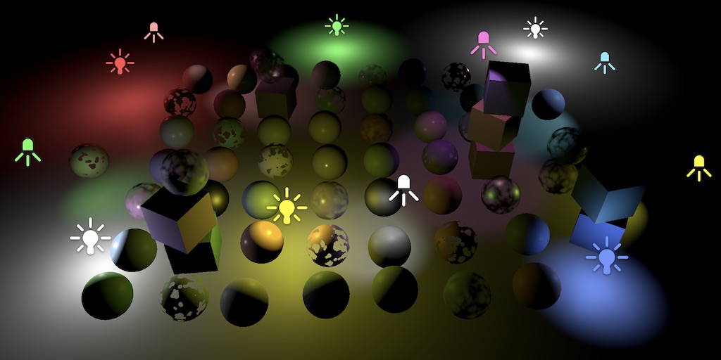
How would I go about determining if one shader code is more performant than another (inside the unity editor). The rendering debugger would be good, but im getting too much variance with one instance. Is the best way to just create 1000 instances to reduce measurement variance? (But then I have to worry about Unity batching things for me when I don't want it to optimize)
That's a pretty good way, actually. Just make sure to do apples to apples comparisons.
Put 1000 (or 500, or 100) spheres in some temp scene, and have the two materials ready. Assign one material to all of them, and play while watching the stats, and then switch the material to use the other shader. Assuming they have the same inputs. Or assign the other material if they have different inputs.
Don't move the camera, or do other stuff. Try to isolate it to drawing the exact same thing, stationary if at all possible.
You can of course check out the profiler, and the profiler api too, and frame debugger.
REALLY testing out this stuff requires vendor tools and shader debuggers/profilers.
I don't recall what renderDoc has for timing data, but worth a look.
I'm actually looking at RenderDoc right now. It has some timing data, but not sure how to use it just yet...
Well, this works similarly to Unity's frame debugger. clicking the clock icon reruns the frame and shows each step's duration. but again the variance is pretty wide so 😐

Though the tool does have a nice disassembly feature where you can see what the pixel/frag shader really does on the register level

I'd like to turn off backface culling for one of the segments of a game object. I read that I have to go into "shader settings". I went into "Edit" of the "Standart" Shader. However there is not really anything I can toggle on/off. What am I misunderstanding?
If you really want to analyze that stuff, you can check the vendor tools. I haven't messed with them in a year or so, but I know they can record and detect "waves" and core groups and register usage and such. Tell you about "vector register pressure" and give you an idea WHY it is taking the time that it does.
If you really really want to dig in that deep.
You can record and play back for debugging too, so you can check the values of variables that way.
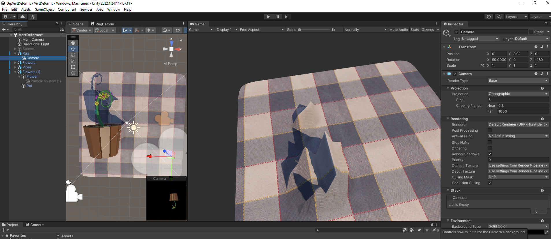
Hi, I have followed a PolyToots tutorial to make a 'rug deform' effect.
This is great except for that the vertices aren't deforming faithfully enough to complex meshes.
Here is what I mean.
https://i.imgur.com/yKPcL7A.png
The FlowerPot mesh is on a layer called 'Deformers' which a RenderTexture camera is looking at.
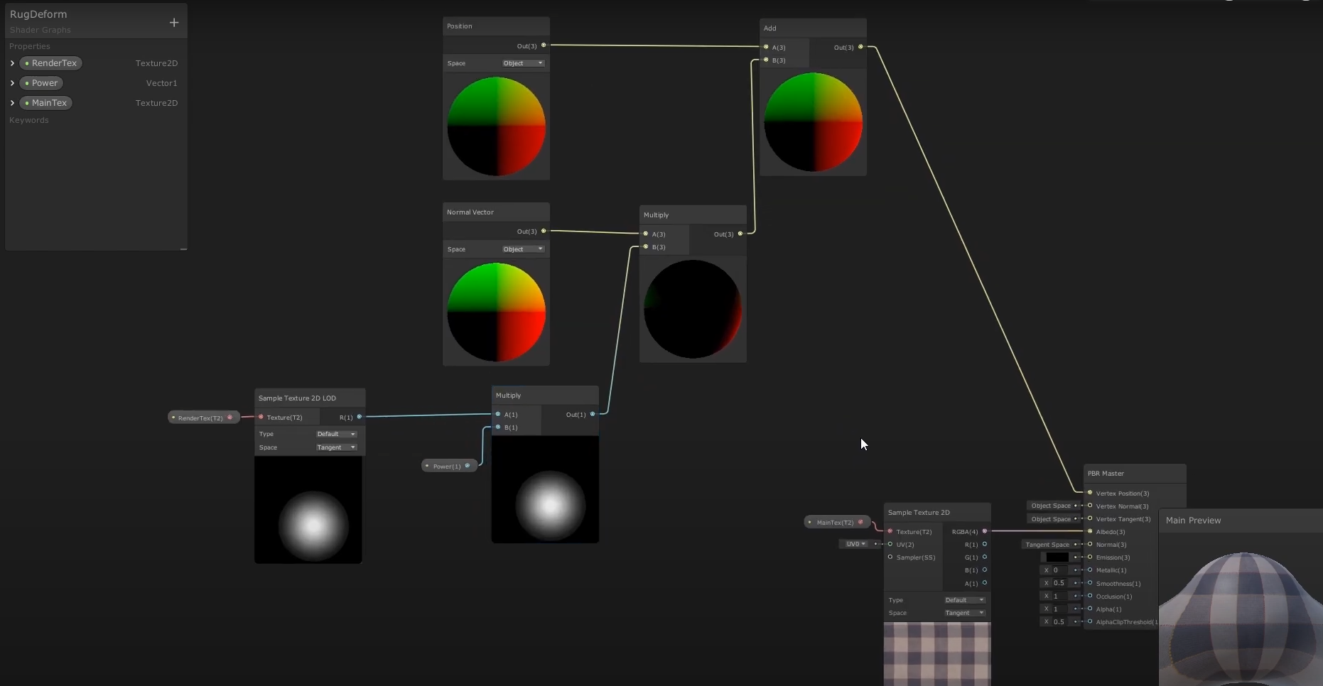
Then a shadergraph says to deform the Rug mesh based on the RenderTexture output.
This is the shadergraph: https://i.imgur.com/ucwqtOm.png
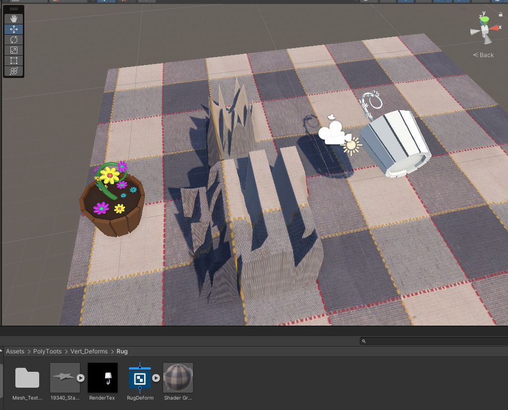
As you can see, the rug is deforming based on the flowerpot's shape but not in an accurate enough way. Is there a way to make the deformation more accurate?
https://i.imgur.com/hRUOxOX.png
Edit: I experimented with a higher polymesh for plane, and white material for flowerpot, and results are 'improved' but still weird. Spiky and overly indented... https://i.imgur.com/Ba7WTt9.png
The written doc wasn't much new, but that video is absolutely fantastic. I'm half way through it and it really helps put everything together for me. Thank you for sharing those!
That's good ^^
Note that the written article is just the first part of 6
Ahhhh, I missed that there were more parts. That makes sense.
so uh quick question, i vaguely know what im doing wrong but im not sure if i completely understand it, but i want per-pixel lighting (which i am doing, a bit of the calculation is in the frag shader) but i am unable to do it in a way that makes it visually appealing on lower-vert-count meshes like this cube that the objects are resting on, which makes sense because im using vert normals which i presume are interpolated across the surface to achieve the effect, what should i be doing instead?
v2f vert(appdata IN)//40
{
    v2f OUT;
    OUT.vert = UnityObjectToClipPos(IN.vert);
    OUT.verttwo = IN.vert;
        OUT.worldcalc = normalize( _WorldSpaceLightPos0 - mul(unity_ObjectToWorld,IN.vert));
    OUT.uv = IN.uv;
    OUT.norm = UnityObjectToWorldNormal(IN.norm);
    return OUT;
}
fixed4 frag(v2f IN) : SV_Target
{
    fixed4 pixColor = tex2D(_Albedo, IN.uv);
        float lightFac;
        if (_WorldSpaceLightPos0.x+_WorldSpaceLightPos0.y+_WorldSpaceLightPos0.z > 0)
        {
            lightFac = dot(IN.norm, IN.worldcalc);
        }
        float3 litColor = pixColor * _Color * _LightColor0 * saturate(lightFac);
    return float4(litColor,1);
}


btw, verttwo is for calculations ill be doing later
mostly irrelevant to this stage of the shader (basic lighting), its for stylization after the lighting is finished
@grizzled bolt @frosty linden (don't worry, I won't keep dragging you along my journey, I just want to post a follow up). I realize what I wanted was the ability to pass UVs to my shader on a per mesh basis (which is really per vertice) which can be done by interacting with the Mesh in my script and then working with those provided values within the shader. The fact that the UVs are specified on the Mesh (really the vertices within that Mesh) is the part I was trying to figure out. One more dot connected on how to make this all work. (don't worry, I won't be abusing UVs for weird things, at least I hope not. They will essentially be coordinates within a Texture / Texture Atlas, if that's the right terminology, still researching).
I am looking for some tips if anyone has any experience with using raytracing for rendering in Unity. Rn I am rendering using a compute shader but the performance is not ideal. I know there's something called a raytracing shader but I don't know if it really makes a difference if I try to use that instead or not, or if that's specifically geared towards lighting and such, or if there are other things I can do or disable in Unity to get some extra juice.
hey there! I'm getting these errors when I try to compile this shader, and I can't seem to figure out why.
https://paste.ofcode.org/3yzWGwuHxMYgGZgRWyDz3g
I'm not sure what I'm looking at in the pics, but my off-the-cuff comments are:
- OK, I'm ignoring .verttwo for now.
- .worldcalc is the light direction vector (lightDir would be suggested as a name instead).
- I noticed that lightFac is unitialized and technically undefined if the if-condition fails.
- I don't understand why that if is there, but that's up to you...I see WHAT it does, but not why you want that to happen.
- The worldcalc/lightDir vector should be interpolated across the polygon for normal polygons (not using POM or other things that fake out the depth of the fragment) since polygons are "flat". Ditto for the surface normal, unless you're using normal maps. The capsule looks lit correctly to me for what you're doing.
So the only thing I don't understand is the if and why you're limiting calculating lighting only when the light has one world-space position component in the positive quadrant. But it either does or doesn't, so I don't see where that's a bug. It SHOULD be doing an NdotL per pixel like you want.
For debugging purposes, you can always output the surface normal, the light direction, and/or the lightIntensity (lightFac) as color results to see if anything looks amiss. You may want to remap them to a 0-1 range to see the results as a color. Otherwise I don't know what I'm missing or maybe don't know what I'm looking at.
ok so i now noticed that i shouldve made it only if it doesnt equal 0, not if its greater than 0, my mistake
also i was focusing more on the cube underneath the objects than the objects themselves
ill think about this some more in the morning
Hello. I have 2 material. The left one uses Quibli Stylize lit shader and the right one uses URP lit shader. I have a spotlight pointed to the wall, why I only have the light on the left wall?

You've misspelt HLSLPROGRAM (line 85)
Is that a default unity cube? You're not sharing verts on that cube, right?
If I'm seeing/interpreting the pics correctly, and the bottom pic is a point light, the point light's NdotL looks correct, the entire top surface of the cube is illuminated. What you're not doing is attenuation of the light (yet).
https://catlikecoding.com/unity/tutorials/custom-srp/point-and-spot-lights/ might help, but note he's using a custom SRP
A Unity Custom SRP tutorial about including lighting for point and spot lights.
If I have two kernels in the same compute shader and I want to set a texture/buffer for use in both, do I actually have to do SetBuffer for each kernel? And won't that cause copied data on the GPU?
or is it just pointing to data
I THINK if it is already there an unchanged, it won't be recopied.
But yes, set it both times.
Alright thanks 👍
P.S. and the reason is that setbuffer sets the context PER KERNEL, that's why you have to pass the kernel index to it. Some kernels may use that buffer, others may not, in the same compute shader.
yeah i just wanted a texture to pass from one kernel to another after writing to it in the shader but i kinda settled on just combining them to one kernel instead for now. seemed better
looks like you are not rendering depth in your render texture just solid white
to have proper deformation you need to render depth
you could also try blurring the render texture afterwards, to get a more real cloth look
are Unity Terrain Trees supported by URP? or deprecated?
This shader takes normals that are close to a camera and stretches them downward.
Does anyone know how to make the stretched normals transparent?

that is the default unity cube
right, so when i include attenuation this should be less of an issue?
and should i write my own equation for attenuation? is there any way to get the pointlights range value?
It wont let me use clip() in a compute shader, but I can't find any information about this not being allowed. I tried doing a pragma target as well but nothing. Is it just not available for compute shaders??
clip/discard is only supported in fragment shaders
i see thanks
wow I can't believe I missed that! thanks!
I'm assuming by 'normal', you mean vertices/triangles? You could put the amount of stretching into the vertex color, and then read that in the fragment side and put it into alpha
Hey, I need to turn the output of a shader into a sprite
anyone know how to accomplish this?
I have my shader done, I have a material with the shader applied, so far so good....
but now I need to get whats on the material into the Sprite property of a SpriteRenderer, one way or another
I know how to turn a RenderTexture into a Texture2D which can then be used in Sprite.Create to create a sprite from it, but my output from the shader is a material, not a render texture
Any way to fix the mipmaps not taking texture scale into account?


They are mipping way too early. Doesn't happen with default URP material
!collab

📢 Collaborating and Job Posting
We do not accept job or collab posts on discord.
Please use the forums:
• Commercial Job Seeking
• Commercial Job Offering
• Non Commercial Collaboration
https://i.imgur.com/aEtWhix.png
success!
was way more complicated than expected, but I got it!
https://forum.unity.com/threads/how-can-i-access-the-properties-of-point-lights-or-spot-lights-in-a-shader.529344/
It can't be simple, because life.
lol
But if I were you and just playing with lighting, I'd start by hard coding something simple, and then build on that.
I think if you can get the light info at all, it's in the .w component stored as 1/range. But see all the complexities in that post above.

Unity Forum
Hi . I would like to access the properties of lights in a shader. Properties like positions, attenuation , etc.
I know I can access them up to 4 point...
☝️
alright
hey guys i need some help setting up URP in my game
i've imported some assets for water, but those textures dont seem to import and the lightning doesnt seem like it's changed
can someone help me out in a voice chat maybe? because im not even sure where to start
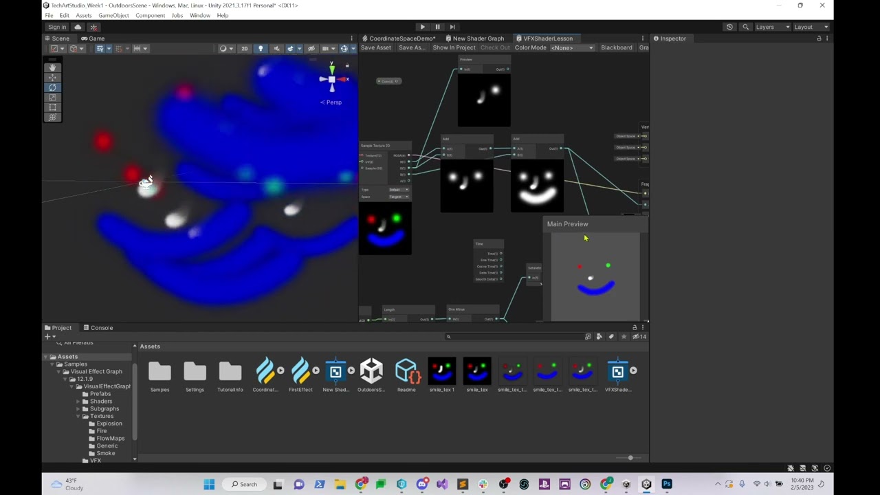
does anyone know how an Unlit shader's Base Color and Emissive Color interact in terms of the shader's Render Pass setting, being Default or After Post Process? After Post-Process seems to result in a final output color of Base Color + Emissive Color , but if the Render Pass setting is set to Default, it seems less clear. Like an emissive color of white with a base color of red gives a light peachy color
(just a general answer is fine. I'm teaching a class on tech art and we're covering shaders this week but I'm more used to Unreal Engine's situation, so i'd like to know what Unity is doing here so I can explain it to my students)
oh I'm using HDRP, that probably makes a difference here
I see... in the end I fetch the screenpos from script using Camera.WorldToViewport since I think it would be more effective than calculating it inside shader
https://www.youtube.com/watch?v=sqE7JVW_NNw one other thing: can anyone explain why this color artifacting is happening while using the premult blend mode? I can make guesses but guesses don't do much good for my students :P. I know how to solve the issue as well, I'd just like to be able to explain what's going on here in this incorrect setup
Thank you! Still trying to figure this out but sounds doable.
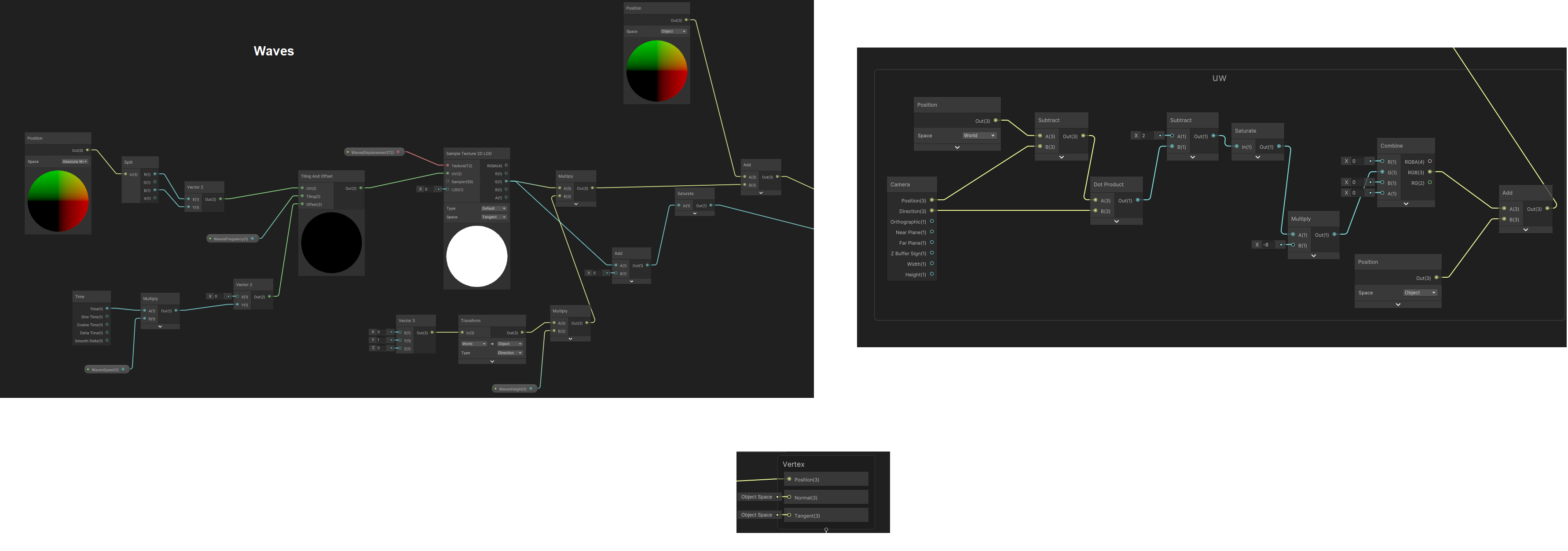
I have another question. I'm trying to use an 'underwater' shader effect that forces vertices downwards if they're close enough to the camera, so as to create the illusion that there is water continuing underneath a water-material plane mesh instead of empty space.
However, I am also using a "waves displacement" node group, and I can't figure out how to get these two node groups working well together.
The effect of each group works fine individually when plugged in to the "Vertex-Position". But I need to find a way to get both effects to apply together into vertex-position.
I have tried Adding, Multiplying, and Lerping these two groups together but each way results in visual problems. Of course, I could have done these attempts incorrectly.
Is there any solution to making them work together or do I have to just do another approach?
Screenshot of node groups...
https://i.imgur.com/nwf6A2f.png
Also, I tried a setup like PositionNode(WorldSpace) -> Waves group -> Transform(ObjectToWorld) -> UW group -> VectorPosition(ObjectSpace) [where the input to UW replaces the UW group's PositionNode] but it resulted in the waves effect being pushed down with the underwater effect, if that makes sense.
Hey I am having a problem of some shader-fu I'm doing not working in webGL
Sprite MaterialToSprite(AfterImageParams e)
    {
        RenderTexture _renderTex = new RenderTexture(e.playerAIRT.width, e.playerAIRT.height, 24);
        _renderTex.filterMode = FilterMode.Point;
        Material _shaderOutput = e.shaderOutput;
        Rect _rect = new Rect(0, 0, _renderTex.width, _renderTex.height);
        Graphics.Blit(null, _renderTex, _shaderOutput);
        Texture2D _texture2D = new Texture2D(_renderTex.width, _renderTex.height, TextureFormat.RGBA32, false);
        _texture2D.filterMode = FilterMode.Point;

        RenderTexture.active = _renderTex;
        _texture2D.ReadPixels(_rect, 0, 0);
        _texture2D.Apply();
        Sprite RT_Sprite = Sprite.Create(_texture2D, _rect, new Vector2(0.5f, 0.5f));
        return RT_Sprite;
}```I've been googling around a bit and it seems RenderTexture class may be the culprit here? I found some things saying that its not supported by webGL
what I'm doing here, in short, is turning the output of a shader into a sprite, through a multistep process
is there another way to get a sprite out of a shader ouput that doesn't involve RenderTexture??
or some other way to get this working on webGL?
Well, it's hard to tell (at least for me) from that video, but I'm sure you know that pre-multiplied alpha differs from the "regular" in that the shader code won't be generated to multiply color.rgb * color.a since this operation is already "burned into" the colors (AKA the color values are pre-multiplied by the alpha already).
Therefore the blending result changes because the values are different each way.
is there a way to display text using shadergraph? for example take a float input number and display it somewhere on the UV?
Nope. But you can scale a float to a 0-1 range somehow, and show it as a color value in the output pixels.
Unless you're using a shader debugger (vendor tools).
thanks, I wanted to make a speedometer, and the only thing left to do was to display the numbers on the large segments
Ah.
Well, you have to generate that result somehow. Like TextMeshPro and having quads with text on them. Or doing that and saving the result to a render texture. Or the easy way is to just burn it all into the artwork, like into a texture.
One way to do that in shader graph would be to use texture atlas to get all the numbers and pass the speedometer numbers in order (probably using 1d texture?) to the shader via c# script so the shader can display them using the atlas
thank you @dim yoke , i'm sure i'll figure something out. until then, I have a very minimalist wristwatch lol
Take the wave displacement group, and plug it in everywhere there is the vertex position, in the stretching group.
(make sure the spaces are the same; e.g. if one spits out an object space position and the other wants a world space position, put a transform node to convert them)
Perfect, thanks so much.
this is what I managed to do with a shader graph (one plane with shader in it), this ⬇️ texture atlas and C# script that sends the digits to the shader by using 5x1 Texture2D. It's certainly possible to do this in shader graph but I'd still probably use world space UI as it would be easier I think but If you are confortable enough with shaders, that could be solution too
@dim yoke thank you, i'll be using this
this is the 320x32 texture that I used for the numbers, may not be the artstyle you are looking for but here it is anyway
very nice of you

https://youtu.be/IC5JoS0wX0s
Followed this tutorial step by step, it works but this bizzare glitch happens on the scope

✅ Get the Project files and Utilities at https://unitycodemonkey.com/video.php?v=IC5JoS0wX0s
🌍 Get my Complete Courses! ✅ https://unitycodemonkey.com/courses
👇
👍 Learn to make awesome games step-by-step from start to finish.
🎮 Get my Steam Games https://unitycodemonkey.com/gamebundle
🔴 RELATED VIDEOS 🔴
3 Ways for a Scope Zoom Effect (Unity Tuto...

public class ZoomShaderScript : MonoBehaviour
{
    public Material material;
    Transform TR;
    public Camera playerCamera;
    private void Awake()
    {
        TR = transform;
        material = GetComponent<MeshRenderer>().material;
    }

    void Update()
    {
        Vector2 screenPixels = playerCamera.WorldToScreenPoint(TR.position);
        screenPixels =  new Vector2(screenPixels.x / Screen.width, screenPixels.y / Screen.height);
        material.SetVector("_ObjectScreenPosition", screenPixels);
    }
}

I guess that the zoom is sampling out of screen pixels.
Try to add a saturate node between "Tiling And Offset" and "HD Scene Color"
Hi. A question: is it possible to achieve the following in URP and shader graph: when (otherwise invisible) object B occludes object A, the occluded part of the object A is rendered differently (the red area marked with C in the image).
This SHOULD be possible, as in many games there are "X-ray" vision kind of features, where enemies etc can be viewed through walls, right?
What I find troubling in this is that this probably requires special 2 shaders, both for object A and B? But how to make the shaders "aware" of each other?

Well for x-ray features you can use ZTest Greater, so that the object only appears if depth values are higher than what is currently drawn (i.e. enemy behind a wall). There's a similar example here using the RenderObjects feature : https://docs.unity3d.com/Packages/com.unity.render-pipelines.universal@15.0/manual/renderer-features/how-to-custom-effect-render-objects.html
But that may not really apply here, since B is transparent and in-front of A.
Instead, you'd want to look into Stencil operations. RenderObjects also provides overrides for that too, which may be useful if the shader doesn't use stencils directly.
https://docs.unity3d.com/Manual/SL-Stencil.html
In short, the idea would be render A to the stencil buffer. Then render B testing against the same stencil value. Pixels that fail the stencil are discarded, so only the overlap would be rendered.
hello. im new to shaders. im trying to send the texture to the shader for post processing but I can't.
    private void OnWillRenderObject()
    {
        Camera.current.RemoveAllCommandBuffers();

        keyBuffer = new CommandBuffer();

        keyBuffer.name = "KeyBuffer";

        int tempID = Shader.PropertyToID("_Temp1");

        keyBuffer.GetTemporaryRT(tempID, -1, -1, 24, FilterMode.Bilinear);

        keyBuffer.SetRenderTarget(tempID);

        keyBuffer.ClearRenderTarget(true, true, Color.black);

        foreach (GameObject o in outlineObjs)
        {
            Renderer r = o.GetComponent<Renderer>();

            if (r && keyMaterial)
            {
                keyBuffer.DrawRenderer(r, keyMaterial);
            }
        }

        keyBuffer.SetGlobalTexture("_KeyTex", tempID);

        Camera.current.AddCommandBuffer(CameraEvent.BeforeLighting, keyBuffer);
    }
Thank you, I will take a look at this Render Objects Renderer Feature thing, which is totally new to me..
is it possible to set ZTest Greater in shader graph, or do I have to convert my shader to text?
Should be "Depth Test" in the Graph Settings, if you're in 2021.2-ish or higher at least
Is there any possibility to do this by writing shader only for object A? Im asking because the object B is using an existing shader Universal Render Pipeline/VR/SpatialMapping/Occlusion
hello every one i have very very simple shader which i want to convert it to Amplify shader editor (PAID JOB) if someone interested in it send me a dm!
btw here is the shader itself
{
  Properties
  {
    _Color ("Main Color", Color) = (1, 1, 1, 1)
    _Intensity ("Color Intensity", range(0, 5)) = 1
    _MainTex ("Base (RGB) Gloss (A)", 2D) = "white" { }

    _DistortionTexture ("Distortion Texture", 2D) = "black" { }
    _DistortionIntensity ("Distortion Intensity", range(0, 5)) = 0.5
    _ScrollSpeed ("Scroll Speed", float) = 0.5
  }

  SubShader
  {
    Tags { "RenderType" = "Opaque" "Queue" = "Overlay" "IgnoreProjector" = "True" }
    LOD 200
    Cull Off
    ZWrite Off
    Blend OneMinusDstColor One
    Fog
    {
      Mode Off
    }

    CGPROGRAM

    #pragma surface surf SimpleUnlit nofog
    #pragma target 3.0

    sampler2D _MainTex, _DistortionTexture;
    half _ScrollSpeed, _DistortionIntensity;
    half4 _Color;
    half _Intensity;


    half4 LightingSimpleUnlit(SurfaceOutput s, half3 lightDir, half atten)
    {
      half NdotL = dot(s.Normal, lightDir);
      half4 c;
      c.rgb = s.Albedo;
      c.a = s.Alpha;
      return c;
    }

    struct Input
    {
      half2 uv_MainTex;
    };


    void surf(Input IN, inout SurfaceOutput o)
    {

      half scrollX = _ScrollSpeed * _Time;
      half2 uv_scrolled = IN.uv_MainTex + half2(scrollX, 0);

      half distortion = tex2D(_DistortionTexture, uv_scrolled);

      half uv_distorted_x = (distortion * _DistortionIntensity * 0.1) - 0.05;

      half2 uv_distorted_xy = IN.uv_MainTex + half2(uv_distorted_x, 0);

      half3 col = tex2D(_MainTex, uv_distorted_xy);
      half3 finalAlbedo = col * _Color * _Intensity;
      o.Albedo = saturate(finalAlbedo);
    }

    ENDCG

  }

  FallBack "Diffuse"
} ```Hello, how should i do caustics for terrain in unity 3D? I would like it to interact with shadows too. Thanks
What is a texture2D in hlsl if I want to do it in a file instead of a string?


I get console errors if I use texture2D
I want to move away from using a string here because its hard to work with

but I cant figure out what to declare a texture2D, nothing seems to work
tex2D function says it takes in a sampler2D and a float for UV, neither of those are a texture
Assuming sg v10.3+, it's a UnityTexture2D. I've got some macros, types and examples listed here : https://www.cyanilux.com/faq/#sg-custom-function-textures
That worked 👍
That explains why I couldn't find the answer, the net was giving me standard hlsl answers, not unity ones
Hello, I want to create a material, with which I am able to see kinda the outer „edge“ of a sphere – so that I only see a circle. And when I am changing my position, I see the outline of the sphere again, but from that position. I googled a lot, but I can’t seem to find a solution. Does anyone know how I can achieve that?
sounds like you are asking for an outline shader?
I don't know what exactly that is, but I think so, yes.
I would try googling 'outline shader' to see if its what you are looking for
I googled and it seems to be exactly that. Can you recommend anything for that to me?
I am not very good at shaders myself, I could tell that's what you were looking for but I don't have the skills to make it beyond that
@bitter forge Is it exclusively a sphere?
Okay, but thank you :) now at least I know what exactly I am looking for
Yes
Then you can probably simply use a fresnel effect. If you're familiar with shadergraph, there is a fresnel node
Sadly I am completely new to that. I have never really worked with shaders
can anyone answer this question? i still have no idea why this isnt working
@bitter forge If you're willing to dive in, and your project isn't using built in rendering pipeline, then just create a new graph.
- Create a color parameter
- Create an outline color parameter
- Create a float parameter for the thickness
- Drag your color/float parameters in the graph, it'll create nodes
- Right click in the graph to add a node, search for fresnel
- Right click in the graph to add a node, search for step
- Right click in the graph to add a node, search for lerp
- Connect your thickness to the fresnel's power input
- Connect the fresnel's output to the step's "in" input
- Set the step's node "edge" value to something like 0.001
- Connect the output of the step's node to the "t" input of the lerp node
- Connect your base color to the lerp's a input
- Connect your outline color to the lerp's b input
- Connect the output of the lerp node to the graph's color input
Thank you very much! I will give it a try. One more question - where do I create a shader graph? I read that when I download the shader graph package, there is a dropdown point named shader in the window tab. But I can not find anything like that
@bitter forge Right click anywhere in the project window. Then Create -> Shader Graph -> Pick your rendering pipeline -> Lit or unlit depending on your needs
Trying to think of a good way to handle hexagon floor tiles that span over curved surfaces... probably facing the kinds of problems tile layers face in real life 😛
Beginning to think the best way to solve this would be with a shader effect instead of hexagon geo.

Normal + displacement height map? Anyone have ideas on the approach that would be suitable?
I see, thank you a lot!
@hearty obsidian I followed your steps now and put the shadergraph onto a material and than that on my sphere. But my sphere is completely filled with the outline material. (Thickness is 0.001 and also the edge value of step's node is 0.001 as you wrote). The only point I am not sure, if I did it correct is the last one - connect the output of lerp to graphs color input. Where is that? I have connected it to the color input of the fragment shader, was that correct?
Im getting undeclared identifier on uvX at line 9 but I don't see why its undeclared

What am I missing?
I added a second texture to the input which had nothing to do with uvX but now UV x is the part that broke

its clearly declared on line 7 in my eyes
Latter part is correct, yes! You should bring the thickness all the way up to make it smaller, I guess labelling it thickness is a bit counter intuitive.
after undoing all my changes returning it to how it was before I added the second texture, now its still spitting out the same error even though its exactly as it was before and it WAS working before
I hate writing shaders so much because it never behaves consistently ._.
this is literally impossible, code that worked before does not simply stop working, thats not how code works
void WhiteoutBlend_float(UnityTexture2D BumpMap, float3 worldPos, float3 worldNorm, float3 blend, out float3 Out)
{
// Whiteout blend\\
// Triplanar uvs
float2 uvX = worldPos.zy; // x facing plane
float2 uvY = worldPos.xz; // y facing plane
float2 uvZ = worldPos.xy; // z facing plane
// Tangent space normal maps
half3 tnormalX = UnpackNormal(tex2D(BumpMap, uvX));
half3 tnormalY = UnpackNormal(tex2D(BumpMap, uvY));
half3 tnormalZ = UnpackNormal(tex2D(BumpMap, uvZ));
// Swizzle world normals into tangent space and apply Whiteout blend

tnormalX = half3(
    tnormalX.xy + worldNorm.zy,
    abs(tnormalX.z) * worldNorm.x
    );
    */
tnormalY = half3(
    tnormalY.xy + worldNorm.xz,
    abs(tnormalY.z) * worldNorm.y
    );

tnormalZ = half3(
    tnormalZ.xy + worldNorm.xy,
    abs(tnormalZ.z) * worldNorm.z
    );
    */
// Swizzle tangent normals to match world orientation and triblend

float3 worldNormal = normalize(
    tnormalX.zyx * blend.x +
    tnormalY.xzy * blend.y +
    tnormalZ.xyz * blend.z
    );

Out = worldNormal;
}
Where is my mistake? how is this not working now when it worked before?
I literally saved out a copy of the working code before changing it, and upon reverting it, it no longer works
Ah yes I see, now I put it to 15 and everything works great! Thank you very very much!! Also shadergraphs are quite interesting, guess I will have a closer look at them now :D
I'd avoid using tex2D in shader graph functions. Use SAMPLE_TEXTURE2D(BumpMap, BumpMap.samplerstate, uvX) etc instead
There's also some comment ends */ in this code (not sure if that causes any errors or if they're just ignored by the complier)
okay there were some /*s floating around but even after removing them I still get the same error
What is the reason to not use tex2D?
I assume its more than just preference
The code I was given instructed me to use it so I am hesitant to diverge even further from it when I can't even fix it as written
void WhiteoutBlend_float(UnityTexture2D BumpMap, float3 worldPos, float3 worldNorm, float3 blend, out float3 Out)
{
// Whiteout blend
// Triplanar uvs
//float2 uvX = worldPos.zy; // x facing plane
float2 uvY = worldPos.xz; // y facing plane
//float2 uvZ = worldPos.xy; // z facing plane
// Tangent space normal maps
//half3 tnormalX = UnpackNormal(tex2D(BumpMap, uvX));
half3 tnormalY = UnpackNormal(tex2D(BumpMap, uvY));
//half3 tnormalZ = UnpackNormal(tex2D(BumpMap, uvZ));
// Swizzle world normals into tangent space and apply Whiteout blend
/*
tnormalX = half3(
    tnormalX.xy + worldNorm.zy,
    abs(tnormalX.z) * worldNorm.x
    );
    */
tnormalY = half3(
    tnormalY.xy + worldNorm.xz,
    abs(tnormalY.z) * worldNorm.y
    );
    /*
tnormalZ = half3(
    tnormalZ.xy + worldNorm.xy,
    abs(tnormalZ.z) * worldNorm.z
    );
    */
// Swizzle tangent normals to match world orientation and triblend
/*
float3 worldNormal = normalize(
    tnormalX.zyx * blend.x +
    tnormalY.xzy * blend.y +
    tnormalZ.xyz * blend.z
    );
*/
//float3 worldNormal = normalize(tnormalY.xzy * blend.y);

Out = tnormalY.xzy;
}```this version of the code works
but I dont understand why it works
all I did was comment out some useless parts I didnt need
but when un-commenting them because I needed them again, it stopped working
which doesnt make sense because all i did was revert it to how it was before, which WAS working
There's 2 texture syntaxes in hlsl. sampler2D name type and tex2D(name, uv) is an older syntax. Texture2D name, SamplerState sampler_name and name.Sample(sampler_name, uv) is the newer one. This page goes over this too : https://docs.unity3d.com/Manual/SL-SamplerStates.html
Unity SRPs/SG implements their own structs (i.e. UnityTexture2D) & macros (i.e. SAMPLE_TEXTURE2D) to automatically use whichever syntax is required to support the target platform. Again see : https://www.cyanilux.com/faq/#sg-custom-function-textures
I see I see, reading
So I needed to get the albedo from the gbuffer of textures that are on objects
I was doing this by adding together the diffuse albedo and specular albedo, but in some palces this messes up with specular being a white, when the texture is red for some shaders
is there a way to get just the albedo of the texture of the mesh on the screen?
basically I need this(but this is wrong because here the specular is a white that gets added on top, making it washed out)

I want to make a shader that had a couple sounds (an array) in its data, references to them, is there a possibility to add to the shader code if it is on collision or not?
This would be used for collision sounds
Have you checked out the Deferred rendering path's G-Buffers?
those are what I am accessing
Hmm....and specular is mixed in? I thought that was a separate buffer, but I admit I haven't looked it up lately.
it is a seperate buffer but you have diffuse albedo and specular albedo
if I only use the diffuse then metallic objects ar black
if I combine diffuse and specular then specular is always non zero
I have an issue where a shader isn't appearing inside of a vr build. Adding the shader to included shaders isn't working. Also this issue happened after a merge from source control. Any ideas?
Sorry, that's the best I had. :p
I mean, this question "is there a way to get just the albedo of the texture of the mesh on the screen?" sounded like the diffuse buffer. Thought I had a "win". lol.
you good, it threw me too
Not many ideas. I mean, you could try assigning a "shade it red" shader as a fallback and see if it gets called instead. In that case the shader isn't compatible with VR, but that's a wild guess admittedly.
Also check the build logs.
Can someone help me with this?
I want to make a shader that had a couple sounds (an array) in its data, references to them, is there a possibility to add to the shader code if it is on collision or not? The end result should be that I am able to have a audioclip array in the material inspector, for impact sounds
This would be used for collision sounds
I don't think that it is possible to reference audio clips from a material (or shader), beacuse the graphics hardware doesn't care about sounds.
Also, this might not work once you consider that the visuals of an object aren't necessarily using the same geometry, or maybe only one of them is present on the same object.
Instead, you might want to use a script to store the references to the audio clips, and select the right one to play.
I was thinking thag
Can a shader store a String?
I already have an audio library that could work if I can reference strings
I'm still not so certain why you want to attach this kind of data to your shaders/materials. Shaders and materials are used to render your objects, but not to hold any kind of data that might be necessary for other systems the objects might interact with (e. g. playing a sound). In order to retrieve the data, you would need access to the MeshRenderer to get the Material, but instead you could use GetComponent to retrieve the component that actually stored the data for the sounds and retrieve the data from there.
The reason I want to do this is for ease of access, one, and two because each material could have its own SFX for impacts, making it each material unique
I'm trying to copy what Source does with its Materials and Audio
You could create a "SoundDatabase" that contains a dictionary mapping sounds to materials, and use the material of the object to look up which sound to play. This falls apart however as soon as you have MeshRenderer with multiple materials, or once you can't distinguish which material should be used, or maybe also with a Terrain and its blended textures.
Yes, it would simplify things for the editing if only a single material needs to be assigned in order to adjust multiple properties at once, but there are also drawbacks to this. I guess the problem here might be that the Source engine has a different concept about what a Material is compared to Unity.
Fair yeah
I was thinking "what am I gonna do with multiple materials?"
I mean, at that point, just make a script, which I kinda already have
Thanks for your help
im trying to make an effect that results in the object being completely transparent, but even when alpha = 0, theres still a wierd lighting reflection

ive been playing around with the settings, but nothing completly removes the effect
(shown on the left capsule)
Hello, Any idea why I am getting z-fighting on Built In when the camera is far from objects? Increasing Clipping Planes on the camera has no effect on this issue. The object with this problem is using a semi transparent Shader. I appreciate any help!
That looks like the specular part of the shading, I can't tell though how you could disable this...
z-fighting can happen with anything, within the limits of floating point precision. It's a modeling error, not a rendering error nor is it a shader error. This is why changing the clipping planes didn't work, although you might perhaps REDUCE the distance between the near and far planes. The only solution that I know of is to remove the overlap itself.
Or possibly reduce your visible world size so you don't run into the floating point precision problem.
Like @gusty rune said, that's specular/environmental lighting.
The only way I can think of doing it is to either use a shader that takes alpha into account with the specular/environmental lighting (like multiplying those things by the alpha value) or swapping the shader out when alpha is near-zero...perhaps even better if you could just disable the drawing entirely. I mean why draw what you want to not be drawn? There's an old saying in CG...the fastest polygons are the ones you DON'T draw...so don't draw it if you don't want/need to see it.
This effect was done in shadergraph, is something like that possible without going into code for it?
Firstly, do you have to draw it at all?
not if its fully invisible, no
So this might be a bit hard to explain, but I used a normal map to make it so this grid only appears when a light is put on it. I want it to look like the second image from all angles, but half the time it looks like the first. Is there something else I can do, should I not use normal maps? I previously put this in lighting but I don't actually know if it should go there or here. Sorry if I'm intruding on conversation


Then don't!
What render pipeline?
But for the nearly-invisible, you'd have to show the shader. I assume you're using a lit shader, and that's why you're having a problem, but maybe show it so we can discuss. Maybe change the spcularity somehow as alpha approaches zero. Depends on HDRP vs URP, but the master stack has some inputs that impact that.
nevermind, I figured something out
I appreciate your willing to help, but unfortunatley ive got a meeting in 25 mins i must go to, but from your information i think i can figure it our from here. Thank you for your help!
Grids are often a shader thing.
You're not intruding, Discord is asynchronous.
I've not done a grid with a normal map, but I could see where it would have issues at different angles.
But they are not overlapping, it works well when the camera is close to the object but when it moves away there is z fighting
I think this usually happens if the shader use emission to show the specular, iirc emission doesnt automatically affected by alpha, so you need to multiply the emission with alpha manually
There's a limit to floating point precision. That's why I mentioned world-size.
I mean, Unity encodes the depth value (z) so as to try to deal with this, but there's only so much it can do.
How far is the far plane?
I understand, far planes are 0.001 and 1000
However changing any of them didnt had effect
I might need to resolve it using a LOD mechanism then
Hmm.
1000 isn't all that bad. Not sure why you're getting this.
If you'd had 100,000 for far plane...well yeah.
Does upping the near-plane help any?
I have a complicated shader that gives the appearance of 3D print lines.
An earlier version of it used World-space coordinates, world normals, world position
I want to switch it to use Object space everything, which I did by changing everything to object, but now I am having a problem.
I want to set up a vector 3 to rotate it's object position, but I can't seem to figure out exactly what I want to rotate to make it act the same as if it had been rotated in world space coordinates

How/what do I do to simulate rotating an object in world space to object space?

this alone wasnt enough, it doesnt behave the same as if it were world space rotations, so I assume rotating in world space is doing more than just this and I need to account for those other unknown changes
why do you want it in object space?
Because I don't want it to move or change or do any of the things it does in world space
but I want to be able to 'rotate' the mesh in-shader and mimic what would occur if I had rotated in world space
without actually rotating it
at no point is actual rotation occuring to the mesh or object
can anyone please answer this question
@serene creek @meager pelican It can also be a rendering error, particularly if it happens specifically at long distances
The suggestion to bring near and far planes closer should work in that case
The closer the near plane is, the more likely geometry will get squashed together close to the far plane and z-fight
is there away of fading alpha of shader based on cameraposition to the planes vertices?
@grizzled bolt Yeah, good point, but they mentioned changing "any" of them didn't help, so I'm assuming it was tried.
However, it's a settings issue, not likely a bug in the renderer. I'm surprised that it showed up with a max range of 1000, so the only thing I could think of was that .001 near plane
nvmi got it working
I just assume the correct settings weren't changed "well enough" which can happen to the best of us
It also depends on how close the surfaces are together, a small gap will disappear to rounding sooner
Road decal geometry for example can be visible far but easily too close to ground
Is there a way to get multiple render textures, each rendered with a different material?
Yes
how
Just do like you said : multiple render textures, multiple materials, multiple blits (or use custom render texture for the easy use)
it worked after adding that and increasing FOV of the camera, thank you
wait no it started happening again
wth
okay so it works properly only on maximized mode
something about resolution messes it up as you said
How can I make the green edge a hard line straight across instead of arced?

I have tried pulling out the green at earlier stages but I cant seem to get the line I want
hm maybe I am getting somewhere with this

It's a sphere, so I assume it'd have to depend on view direction to be completely linear
its not always a sphere, thats just the preview
I want to use this on meshes other than sphere
making progress but now I can't figure out how to prevent division by 0 here

you can just add a tiny value to it so that it isn't zero
I tried that but it completely destroys the mask im trying to build

maybe clamp the value between some values
i think if you do step(abs(g), threshold) it'll make straight lines
but to get all three to line up you'd need to find the right value of the threshold
Step makes a line that is too crisp, smoothstep maybe though
yeah smoothstep would work

i think 1/sqrt2 = 0.7071... is the right threshold value?

1/sqrt3 = 0.5773503 , as we are in 3 dimentions 🙂
i was looking at this one where the circles touch on the edges, for this i think it's 1/sqrt2?
bc the contact points form squares

The R/G/B contact point is the "corner" of a cube, not a square
This sorta works but doesnt meet my use case, I need to adjust where green is, and red and blue don't extend all the way to the top behind it
in this image though

Yeah thats a problem ^

if I remove the third channel I get divide by 0 problems
but if the third channel is there, red an blue dont extend all the way to the top

this doesnt work either, more divide by zero
?

Is minimum cheaper than multiply?
taking the minimum or multiplying are two different operations
Use of step is confusing me, I dont want super hard edges
this is for tri-planar so I need smooth-ish edges, I need to control the smoothness with a value
They are different, not sure if minimum is heavier. Maybe
Then use smoothstep
I dont know how to use it in your set up
replacing step with smoothstep has different values
In this case they have the same result though
Replace steps with smoothsteps
replacing step with smoothstep has different values
step takes in two, smoothstep takes in three,
Ill just try to figure it out myself
I'm trying to help, but please do some effort

I'm sorry that I am much less experienced than you on top of being extremely stupid
well that depends on what you did with these operations, but they are two different operators, but I would not know what would be faster
i am going to step away for a bit because the barrage of put down critisism is getting me agitated. Thank you for assisting me get this far
It's not about experience or beeing stupid, it's about the attitude .
I've only had the time to write that you should use smoothstep that you complained about it without even trying by yourself / reading the doc / testing how the values affect the result.
Historically a multiplication is one of the bases of vector math, so I suspect that it might be faster.
Now, min/max operations are also quite common (they are even available as blending states) so there might by some fast path in the compiled assembly for them.
I've showed using min as is the operation for intersections
Tbh. I do not know what he was doing but it probably doesn't really matter
thank you for the kind and supportive words 🙏
@amber saffron I just found a better shader tutorial and now it works like a charm, thanks anyways
Good idea, I'll try that.
Here's the zoom shader that works, all I need is to add a texture2D on top of it

and I have no idea on how to do that
ah so that was a question lol
what exactly are trying to do?
a sniper scope, zooming works, I want to add a reticle on top of it
a png texture
you don't nessesarily need a shader for that, that can just be some simple ui
Yeah I just duplicated the glass mesh and made another material with an unlit transparent shader. This works fine but I don't wanna use extra gameobject/mesh renderer/material just for this yk

glass mesh?
oh is it some scoped rifle or something
yeah
well you can just use a sample texture 2D and overlay it


goddammit
could you please show me how?
in this shader specifically
yeah do it in that shader
Im on my phone, but its really simple just add that texture to it
Hi how do you set a smoothness map on a material?
Hello this might not be related to shaders, but thats the closest channel to this issue that i can find.
So i made this in blender as just an example item for later ones, but i am having an issue where i can't find a way to transfer over the checker board pattern that was created by blender over to unity.
Blender:

heres how it looked right after importing

Heres how it looks right now, i just removed the glow and set its colors. Tho the checker board patter didnt transfer over

Under blender it is not a texture, but it is generated as shader i beleave by blender it self.

Help?
How do i transfer that patern over to unity
How do I add a second texture overlay in a custom sprite lit shader?
fastest way is to just create an 8x8 texture
paintDotNet is your friend
How do i know how big each of the checker things need to be tho?
1 * 8 pixel?
and then in unity i will be able to scale it up?
unwrap the UV of the checker top to be the default square aize
then 1 pixel per
import the texture into Unity with Point / None filter mode
Ok ill try tomorrow
Quick question about player UI's in vr. Can i add any image as a button?
U should be able to, but #🥽┃virtual-reality might help you set that up a bit better
Is there a reason there's so few examples of shaders with HLSLPROGRAM? I understand that CGPROGRAM is older and therefore has a legacy of tutorials and examples, but hasn't HLSL been the go to syntax for a while? Is there a reason Unity 2022 is still defaulting to CGPROGRAM when you create a new unlit shader? Do folks still generally write with the CG syntax and just let Unity compile it into HLSL for them?
How do I blend two textures, and make the black layer transparent? Ive tried multiple methods and can only get one textures 50% transparent by lerping by 0.5f. How do I remove the black layer to show the texture underneath

for context, here is both layers

Typically you wouldn't have black pixels in the texture you want to overlay, they'd instead have an alpha channel and be transparent. That way you could just use the A output in the T of the Lerp.
But otherwise you could also use some math to test if the pixels in the texture are black. Either with a Color Mask node, or since black is a value of 0, Add all the channels together and use a Step node (or Comparison + Branch). Again use that result in the T of the Lerp.
Is it possible to change which shader this material is using but inhereit that color field into the new shader?
I need to change a looot of materials and I was hoping if I just name it something it will just work instead of a ton of manual data entry

MY hero! Thank you. Played around with what you said and got results 🥲

Naming my color "_BaseColor" did it 👍
For the built-in RP there's not really a reason to switch to HLSLPROGRAM, especially given the amount of resources/tutorials as you mention. Either way it's still hlsl - CGPROGRAM just includes a few built-in shader includes, (HLSLSupport.cginc and UnityShaderVariables.cginc, iirc). That way you automatically have access to some macros and variables (like _Time, unity_ObjectToWorld, etc).
But yeah, when writing shaders for post processing v2 stack/package and other render pipelines, their ShaderLibraries replace those built-in include files, so we must use HLSLPROGRAM there or it causes conflicts.
I imagine there's less examples of shader code for URP/HDRP since it's easier to just use Shader Graph, especially due to the lack of surface shader support. But you can always look at the shaders those pipelines have in the package files / Graphics github (https://github.com/Unity-Technologies/Graphics)
For URP I've also got https://github.com/Cyanilux/URP_ShaderCodeTemplates (though it was written for v10 which is a little outdated now)
Mighty Sensei of shaders, would you happen to know if it's possible to clamp the max light contribution for a mesh from lightprobes to prevent certain objects from being grossly overexposed when they get too close to light sources?
I've been desperately searching for a solution for this problem for days now and am starting to lose hope 😦
Idk if this is specifically a shader thing, but this seems like the best place to post this. I'm making a toon-ish game where everything has the same material with uvs mapped to colors in a texture which is basically just a color palette. This works well and it makes things pretty fast for me.
But I have a few models that I want to have different colors. Pretty simple, like a cube that is blue, a cube that is red, etc. Not exactly that, but just as simple.
Is there a way to basically remap the UVs in unity so I don't have to export several meshes with different uv maps? I suppose I could have different materials with different versions of the palette texture, but that sounds less easy than having multiple meshes.
is there a way to get the edges of a mesh
like an outline?
sort of
I can't help you with the information: sort of
*currently trying to figure out how to phrase it
like synthwave but instend of cubes its whatever shape the sides of the mesh are
I do not really know if you can change uv maps in unity but using different models with different uvs is cheaper then having different materials with different shaders, simply said it reduces draw calls
that synthwave?
I am still confused are you asking how to do that synthwave or how to get the edges of the object?
how to make my game look similar to this

there is more than just one thing going on there, show me an example of what you want
all I can say now is lots of bloom, the black object in the background seam to have a subtle outline, and then we have these streaks on the ground which are also just emissiv materials
the streaks on the floor?
ye
or the glow around the object?
both
the streaks are probably just models with an emissiv material
the glow around the object is just bloom
the glow around the dark objects is an outline
+bloom
Idk if anyone cares about this but me, but I wanted to share just for posterity's sake.
In Blender I made several UV maps for my model, one for each color I want in the texture. The order of these matters.
Then in Unity I made an enum with the names of each UV map in order. Then they can be switched on the mesh filter like this:
var uvs = new List<Vector2>();
meshFilter.mesh.GetUVs((int)uvMapNames, uvs);
meshFilter.mesh.SetUVs(0, uvs);
And that's it. My use case is a little more complex because there is an object with several meshes in it and only some of them have multiple uv maps. So I just iterate through and if GetUVs() returns an empty list I ignore it.
I put the UV swap in the Awake() of that gameobject and when I press play the colors immediately change to whatever I want them to be. No preview in the editor, but I'm ok with that.
thats pretty cool
How would I use one sprite from a sprite sheet for a texture?
currently its using the whole sprite sheet


"Is there a way to remap the UV's in unity"....well, the UV's are an attribute of the mesh object. Although, as you note, you can make several copies of a mesh and put unique UVs on each copy. I suppose if you have to special case a mesh, you could, instead use some kind of override...perhaps a texture or a data array...and pass a switch to have the shader use that instead of the UV embedded in the mesh data. If it's as simple as "red cube" vs "blue cube" just pass a switch and a color, and use an IF to check it in the shader.
AKA you'd have
float4 overrideColor;``` declared in the shader and set that value on the material instance for that mesh.
If it's a solid color you could pass that on from the vertex stage to the fragment stage, so you'd do the IF in the vertex stage.In addition to this, meshes can also contain 4 sets of UV's so if one needs special behaviour based on custom UVs, just bake your data in the other UV's
Hey i think i did as you said or i missed a step? i made the texture is photoshop and exported it, but now it looks like this when added to it

size is good its just that the pixels dont show as pixels but more just blured out
also the little second image is the 8x8 pixel image
In the texture import settings, set filter mode to "point"
like this?
i did it but nowthing changed
The actual texture asset 🙂
Make sure to hit apply!
How to debug a HoloLens application using RenderDoc? The editor switches to mono rendering during initialization, but I need to capture a separate eye.
Am I right in thinking that it's completely impossible to make a first-person shooter using deferred rendering in URP? You can't use camera stacking to render the guns in front of everything else. Also, using custom renderer features draws the meshes on top of the level, but then the meshes within the gun on the top layer don't write depth. Is it literally impossible? (I HAVE to use deferred rendering)
Thank you so much, is there a way to also set the other faces of the object to be black? bc atm one of the faces is white, one is glowing for some reason

if i want one side to be checkers and other faces of the mesh to be black or white what do i do
- Use a dedicated mesh, with different materials per polygons
- You can use probuilder (additional package in package manager) to edit the mesh
- Use different objects per material
Many options
Also another quick question when i enter the game the board is light up as if it has its own light, i tried removing the directional light, but that didnt change anything in the board it just made every other mesh black bc of no light
How do i make it so it dosnt glow/emit light, as no matter how dark i make the light around it it still can be seen like before
Seems like the material you are using for the board is either unlit, or you plugged the texture into the emission channel
Hi everyone, just cross posting here since it's shader and terrain related #⛰️┃terrain-3d message
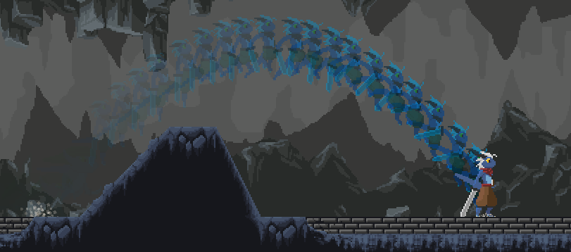
hi hello can someone help me with this water shader the bands are suppesed to come out of the meshes but instead it is moving with the camera.

its unlit. What type should it be then?
nvn i figured it out
i tried using sprites, but then i cannot change the tiling
it becomes this when setting it to sprite texture

Lit
What are you using to create the bands? If it's depth, they'll only appear where the water is in front of the capsules (which i think is what you can see if you look carefully around each capsule). That method for creating foam works well if you've got large objects, usually with fairly shallow gradients going into the water. It doesn't work well if you have very small objects or sharp jumps in depth.
Thanks
google results say you can get Unity to render both sides of faces (backfaces), but it seems like no one really knows how to get it to work anymore. i tried a bunch of different methods, but no luck. do you guys know if figuring this out in Unity is even worth it, or should I just create the geometry on my 3D model?
Soooo, I have a plane that my character walks on (fps) and I want to have it so it gets transparent the further away from the character (ie, have the character walking around on an opaque 'disk' with a fade off into the distance.
I know I need to have position and camera nodes going into a distance node and then an 'amount' float node to control the distance of the opaqueness, but I'm drawing a huge blank about where to go from there.
Could anyone help out a little please?
HDRP Shader Graph btw.
I'm surprised that you cannot force it to write depth, but you may need to set the proper depth buffer on the camera.
Also see here for some funky stuff: https://forum.unity.com/threads/urp-deferred-camera-stack-not-possible.1204534/
Unity Forum
Unity 2021.2.3f1
Universal RP 12.1.1
I'm using camera stacking to render first person weapons with a different field of view on top of the rest of the...
Depends on the use case.
The usual problem with backface rendering is that the normals have to be inverted on the backfaces or lighting won't work properly. Whereas if you render a full model with forward facing "other side" it will have proper normals. It's actually a good way to do it if you're good at modeling, and it "just works well".
For example a playing card...I'd use a double sided model for that.
Thanks! That's really helpful to know I'm not creating extra geometry for no reason or when something can be easily checked in Unity. Makes sense to make the models with both sides when needed.
What are the best resources for learning compute shaders?
Sure, it all depends on how you define "when needed". I mean, if you have a very complex mesh, it might be nice to just handle it in the shader, it's not all that bad. But then again, GPU's process polygons in the millions, so for a playing card, meh. And you can use all the same uv sets because they're all front facing polygons. So UV0 is UV0. Otherwise you tie yourself into knots doing "is backface, use UV1 otherwise use UV0" or whatever. Why bother for only a few polygons extra?
YMMV. It is possible to show the backfaces and invert the normals. And deal with the UV mapping.
Thank you
I'm just gonna post the question I posted in Youtube Answers to not repeat myself.
https://answers.unity.com/questions/1938514/lit-cutout-shader-in-universal-render-pipeline-urp.html
I'm on a tight schedule so I can't afford to start learning shaders from scratch, can anyone help me out or point me to where I can learn how to do what I'm asking about?
Unity is the ultimate game development platform. Use Unity to build high-quality 3D and 2D games, deploy them across mobile, desktop, VR/AR, consoles or the Web, and connect with loyal and enthusiastic players and customers.
I think the lit shader has an alpha clip option, is that what you want?
Turns out I didn't even need to turn on that option, URP handled everything on it's own once I switched to the lit shader, but thanks for pointing me in the right direction.
No wait, I did turn on alpha clipping but somehow didn't realize it, my bad, thank you.
Is it possible to use triplanar + parallax occlusion mapping?
Hello! I am trying to make a border shader for hexagons that use decals. I am using URP and the issue is the decals are rendering below water which is in a transparent render queue. I have tried forcing the water shader to use depth write, but the decal still does not respect it. I want the decal to project ontop of a transparent material. Any ideas on how to get the decal to do that?
hey, is it not possible to make a wireframe shader with shader graph?
https://forum.unity.com/threads/shadergraph-highlighting-edges.557005/ it is but requires some extra work
Sometimes people refer by "wireframe" a triplanar grid which is much easier
IDK, but as a wild guess you could try writing the water in the OPAQUE queue, write depth. You may have to use layers to get it to render on top of everything else. But you won't have an opaque texture yet, unless you're camera stacking. And you haven't indicated what pipeline you're using.
I'm assuming your decal process is after opaques.
I suppose the best option would be to change the queue of the decal writer to be after the water shader that writes depth.
I need help on doing this
how do i get objects position in shader
Shader or shadergraph ?
Sample texture node, and blend node
shader
You can use the unity_ObjectToWorld (https://docs.unity3d.com/Manual/SL-UnityShaderVariables.html) matrix .
Either multiply by the (0, 0, 0, 1) vector, or extract the translation.

i tried it before but it doesnt work

green objects are exactly same color
If you are trying to output the position in color, doesn't it seems obvious ?
What would you expect position value (25, 8, 0) to display ?
Is there a simple tutorial on how to make procedural 2d grass textures?
Aiming for something like this but 2d

Date of Recording: 2020-10-05
In order to evoke a pixel art aesthetic, a 30 degree pitch isometric camera that snaps the yaw to 45 degree increments is used. This can perfectly reproduce the 2-pixels-across-1-pixel-down look of rectangular pixel art blocks, while still allowing smooth camera motion between snapping regions.
I made portals so when the player collide with the 1st he transport to the 2nd
I made dissolve shader starts when the player collides
when I put the player besides the portal then start the game.. press D to move and collide with the portal .. the dissolve does not happen
But when I put the player above the portal and start the game he falls by gravity on portal and the dissolve is running ok
can anyone tell me why this is happening?
( I’m using a new input system)
well it sort of worked, still trying to get that png to view with its transparency

tried this

You'd likely want to connect the A output from the texture to the Opacity port, and use Overwrite mode.
it worked beautifully, thank you and thank you Remy
I'd assume the player might start inside the trigger radius, in which case the collision method isn't called. Or perhaps you're altering the transform of the GameObject rather than using Rigidbody movement. May want to ask in #⚛️┃physics or coding related channels as this is outside the topic of shaders.
I tried the old input system and disabled the new one .. it worked!
why the new input system is causing this?
Idk, I don't use the new input system, ask in a more appropriate channel
Does it need to be procedural? The example video you give appears to be using textured quads scattered over the terrain, I imagine something similar could be done in 2D too.
Procedural would be preferred, thanks.
why is my water shader graph shader thingy doing this when high or far from the water it has blue thingies and whithe thingies when you go too far

blue from this angle

I'd like to build a damage shader. It should work in a way that if a player attacks a wall then there should be a damage map that looks similar to a heat map. Ranging from undamaged to destroyed. For each color spectrum another Albedo map should be used for that "revealed" section.
Was something like this done before? Would be interested in how it has been achieved
Hey there!
Someone could help me please?
I added a rotate node, but when i set a value, like 90º, the texture doesn't seem to rotate properly, looks like 45, i need to put a very specific value to keep it like I want, as I show in the second image.
I put a rotate just before my images textures, idk if it's the correct way, i'm newbie at this shader stuff, thank you!


The Unit on your Rotate node is set to Radians, rather than Degrees
Wow, is that simple?! haha
Now it's working, thank you very much!
Decals may be simpler to implement depending on how granular the damage needs to be, but systems that fully enable texel variation definitely exist
https://youtu.be/c7HBxBfCsas such as one explained here
Wow interesting project. However I ultimately need the mesh to be see through at some point. Is that possible with decals? Never used them and am quite new to shaders
Decals can be transparent as well but I don't think they can directly alter the texture or other properties of the material below
I see - well ok I think I need to experiment a bit then. I guess when creating a new Shader I also can extend the existing Standard Shaders, eh?
we do not know what you have done
Is it possible to write a triplanar+ POM shader?
Please don't ping randomly
Why don't you try it
Hey! Thanks for the response. When I use the water as an opaque qeuue, it does not show the landscape beneath it. The decal I have on Transparent+001 and the water is on Transprent render queue. The water is made via ShaderGraph and has ZWrite On. Even still, the decal does not respect the depth buffer
Is it possible to write a triplanar shader to output UV instead of color?
There would be 3 uv coords used by triplanar mapping. It's typically the fragment position swizzled (.zy, .xz and .xy), probably with additional scaling (multiplied by some value).
I imagine triplanar + POM is possible but isn't very practical as triplanar triples the amount of texture samples. POM is probably already expensive enough without having to do that.
Is it better to use tesselation then?
can i use it with triplanar?
i`m creating a tile engine, it needs triplanar to look good but without POM it does not look as good
they are square for now

I'd look into proper UV unwrapping of the meshes rather than relying on triplanar. Can still sample both grass + stone textures with those mesh uvs and blend based on Y axis of vertex normals though.
but then it will be repetitive
if i repeat the same tile it will look bad
and very hard to do it seamless
i`m doing it like dota 2 tile editor
they use triplanar too but not POM
Is it too expensive if only for desktop?
Hi all,
I hope someone can help cause this is driving me insane. lol. I'm trying to build a shader graph whereby only the area of the 'ground' close to the player (relatively close anyway) is visible and fades out at a distance (ie, min/max distance) etc. (See image for an illustration as to what I mean. Red is player, dark grey is ground, light grey is ground visible area).
I know that at the beginning of the graph I need camera position and 'world' position into a distance node, it's what comes after that where I'm stuggling. I've seen a couple of videos on the subject but I can't seem to get those methods to work. 😕
Anyone have any ideas please?

Once you've got the distance you'd need to remap it. Could use an Inverse Lerp, with distance result in T port, min and max in A and B. Then Saturate to clamp between 0 and 1. Or could use a Smoothstep, similar but not linear.
Or there's also a Sphere Mask node.
Either of those would go into the Alpha port on the master stack.
@regal stag Thank you, will give those a go 🙂
Hmm......okay, not sure what I'm doing wrong here. 😕
There's the graph.......

That's the result. 😕 So very confused.

Use World space on the Position node
Oh yeah. lol. Thanks.
Okay, well something is happening, but not really what I expected.
The 'ring' is getting alpha clipped but the distance is way off (I have min/max set to 10/20) the ring has a diameter of 240km so I think I'm misunderstanding something about how the min/max distances are being read/applied.

And changing the min/max numbers doesn't seem to do anything at all. 😕
Guys, i'm still learning a bit about shaders.
In unity we have this first one, but the divisions among textures are so soft, and I need something with more "contrast" if i can say this way.
I made this new one (second image) based in some videos I saw, but to painting work properly I would need a very subdivised mesh, and that's not an option for the project we're working now, anyone could show me a way?
It's a mobile project


How are you blending the textures?
With a height map, someone tell me about blend by colors, but I have no ideia how to do that.

Okay, try adjusting your 'blend amount' Lower values may harden up the edges. Failing that, I think your height map might need to be a higher resolution.
The amount is working fine I guess, and the harder edges are the way a want.
But when i try some rounded shape, I can't get a sharp division, idk if there's a way to solve this without using a very high res mesh.

Hmm. Not sure tbh (still kinda learning this stuff myself. 😕
But thanks for trying anyway xD
Okay I'm seriously about to lose my ** about this. I seriously don't understand why, after trying every method I've found/been told about I can't get this damned thing to fade off.

InverseLerp, SmoothStep, no fading at all and SphereMask just makes the whole thing transparent.
Is the following shader using any bumpmapping or displacement?

GitHub
Source code for Toon Water Shader tutorial for Unity. Renders and animates toon-style waves from a noise texture and generates shoreline foam based off the depth buffer. - ToonWaterShader/ToonWater...
I believe so yes. My limited understanding of shader code suggests that this section
`struct appdata
{
float4 vertex : POSITION;
float4 uv : TEXCOORD0;
float3 normal : NORMAL;
};
        struct v2f
        {
            float4 vertex : SV_POSITION;
            float2 noiseUV : TEXCOORD0;
            float2 distortUV : TEXCOORD1;
            float4 screenPosition : TEXCOORD2;
            float3 viewNormal : NORMAL;`
Is dealing with moving vertices on the mesh to displace it.
isn't it just editing the noise and distorting coordinates to "fake" displacement?
I'm honestly not sure, but it's referencing the vertices of the sea mesh.
There's no bump mapping or vertex displacement. Though yes there is displacement/distortion of uv coords.
My bad. lol.
It looks like you might be using Alpha Clipping, but not actual transparency. Check the Graph Settings. If you want it to actually fade, you'd want Transparent surface mode, and disable alpha clipping.
@regal stag Okay, yeah it is set to transparency, will disable the clipping (the clipping before BTW that I mentioned was because of my camera far plane. lol.
You may be able to use a Step node to make the transition sharper, before blending the textures.
Though it looks like this is using vertex colors - you can see with your circle the bottom left and top right are more jagged due to the way the triangles are orientated. The step would also make that worse / more noticeable.
Really becoming frustrated now.
Player is 100m above the object I want fading. Min distance is set to 0, max distance is set to 200, but the bloody thing is still solid. I so don't get this at all.

Camera is attached to player.
What it looks like

What I want it to look like......
(with the transparent bit 'following' the player.


Hmm, I'd expect this to work. Is this in HDRP?
@regal stag Yes it is.
Then you shouldn't need the Camera node, as HDRP's "world" space is already camera-relative. Use distance to (0,0,0) or Length node.
Sorry, didn't realise it was HDRP at first
ok. 1 sec (thank you a lot btw for taking the time to help out)
Still the same result. 😦
And game view (running)

Not really. But the shader is from a tutorial, so this should explain it : https://roystan.net/articles/toon-water/
You could also look up some beginner shader code tutorials if you are unfamiliar with the syntax or structure (e.g. https://docs.unity3d.com/Manual/SL-VertexFragmentShaderExamples.html & https://www.ronja-tutorials.com/post/004-basic/)
Maybe try adjusting min & max now? Maybe like 40 and 50? Or the other way around to invert the fade direction.
Inverting just seems to fade the whole thing. And reducing the min max doesn't do anything.
Just spitballing but would the amount of vertices in the rings model have any effect? The ring is very low poly (ring of segments)

And the width of the ring is 20km.
The amount of vertices shouldn't matter as this is in the fragment stage.
Okay. Just thought I'd check. lol.
But if scales are this large, your min/max values may also need to be much larger
These values would basically be the distance at which the fade begins and ends, to clarify.
I thought that, but as I have the player/camera 100m away from the surface, in my head at at least a min/max of 100/200 should show some fade.
Oh, wait. Something is happening. lol.
Okay, it's sort of working. (at least the fadey part is now.)
But, something else weird is going on. I'm still getting a specular hit on the transparent part. 😕

What is uv-coords
UV's are a 'map' of sorts of the Vertices of a model but 'flattened' out. They allow for accurate texturing etc.
so what does this line do exactly?:
o.distortUV = TRANSFORM_TEX(v.uv, _SurfaceDistortion);
o.noiseUV = TRANSFORM_TEX(v.uv, _SurfaceNoise);
It looks like it distorts the UV Map, thereby giving the texture assigned to the object some distortion.
TRANSFORM_TEX is a macro unity defines, it applies the Tiling and Offset fields of the textures (from the material inspector) to the uv coordinates.
Also again, the tutorial literally explains this, please read it. https://roystan.net/articles/toon-water/
Learn to write a toon style water shader for Unity engine, complete with waves and shoreline foam.
Ah fixed my spec issue. lol.
Out of curiosity, how? Different blend mode in settings or something else?
There's a setting in the material settings 'Preserve Specular something' that was turned on.

Ah cool okay. I typically use URP rather than HDRP, so was just curious in case someone else has the same issue in the future.
But it's now doing what I want it to do 😄
@regal stag seriously dude, thank you. 🙂

Aaah fair play. Yeah I like URP, but wanted to try some stuff with this idea that I believe only HDRP can do. 🙂
RTX stuff mainly. lol.
Has anyone here made a shader for TextMeshPro Text?
Anyone have any insight on how to create a shader in shadergraph that when two outlines over lap one another it hides the overlap part?

Like the image above
Im trying to make a 2D shader and it turns out really weird


im not sure whats happening
is _MainTex not a thing for 3d shader graph?
Seems you are not assigning the alpha channel correctly
Select the texture in the inspector, what's it look like in the inspector preview?
yea, i started to think that I need to create a separate material for every model, and then select thhe texture and add it into the material manually.
I thought it was like in 2d, where _MainTex would just grab me the texture from the spriteRenderer, and then i can just edit stuff.
That gets a bit complicated. Each shader only knows about its own mesh. In order to do what you're asking, you need the outline to happen "after the fact" of them ALL being drawn. That information can be passed in the stencil buffer. However, last I knew SG doesn't support stencil operations. And the process for doing this requires another pass, as I said. So unless stencils are added to SG, you'll have to either generate a shader with SG and then edit it from there, or just hand-write one the "normal way". URP shaders support stencils, just SG doesn't.
Maybe you can find a way to use a separate set of passes and a render texture instead of the stencil buffer, but I don't know of a solution like that. Maybe someone else does.
More about outlines in general: https://alexanderameye.github.io/notes/rendering-outlines/

Different techniques for rendering outline effects.
i want a number to go from 0 to 1 and repeat from 0 to 1 (not go back and forth, just go 1 the max value and repeat) .... what node does that
Fraction
Or Modulo if you need it outside of 0-1 range
thank you, I will try both
hey hey, quick question
is there any way to expose and hide input fields dynamically based on a toggle in shader graph?
fraction is what i need thank you
ok so... I am working in a sprite shader, I want to repeat a texture in a mask of that sprite... I am thinking i should use a tiling and offset node to move the wanted texture.... but how do I repeat it (the tiling and offset only makes the picture smaller or bigger)
if anyone can help please do, I am unable to do this
i did this but i didn't get the same result

ok done.. the problem was the import settings of the texture.
why does my tessellation in the shader graph gett better and at around 5m it gets worse?
Define better and worse
more tessellated is better worse is worse
when it gets closer at around 5m it worsens


Like, when you get closer the triangles get bigger again, or just they don't continue to tessellate ?
Maybe you jost got to the tesselation limit.
closer = bigger triangles
Can you set a float2x2 in a shader from C#?
yeah I did SetVector but assumed it would not set a 2x2 matrix but will check
well something is not quite right doing that - best I got now is SetVector to a float4 and then fill out the 2x2 from that!
As it's a matrix, probably SetMatrix would work ?
Something not working in the tesselation factor math in your shader ?
there is only 4x4
Like SetVector takes only a Vector4 as input, but works on float2/3/4, I suspect that the matrix version works on different hlsl matrices size.
hey, i downloaded a shader file which makes sprites hide behind shadows. how can i make it so the hidden part is completely 0, ad not just like slightly hidden? the only way it would go completely hidden is that if i turned shadows all the way to 1, but that makes the shadows completely black and defeats the purpose of it.
https://stackoverflow.com/questions/65696260/is-there-a-way-to-hide-a-player-who-is-in-the-shadow-in-unity-2d-light-system/67780057#67780057


Stack Overflow
I want to recreate the field of view effect in the game Among Us in Unity by using the Universal Pipeline and 2D Lighting system.
But when I use 2D light and Shadow, I still see the character in the
this is the shader file i used
also, im having an issue where it says this, but the file is in the same folder?
Hello! I'm attempting to create a CRTV shader, and I'm running into the inevitable issue of the "subpixel" pattern causing moire patterns / artifacts at distance, making the text on the screen unreadable
I had seen mentions of using screen space derivative functions to determine when to draw the subpixel mask, essentially removing it when the subpixel pattern doesn't fit inside a certain clump of pixels or whatever
At a very surface level, I understand what that means, but not nearly enough to begin implementing it
If someone is more knowledgeable on this topic, I'd love to know more
guys need help in making a simple 2d dropdown shadow
i have this working right now

but it doesnt work with particles
this looks interesting but i have no idea whats happening and how should i go about using it, since im absolute noob at shaders https://github.com/UnityCommunity/UnityLibrary/blob/master/Assets/Shaders/2D/Sprites/SpriteDropShadow.shade

<@&502884371011731486>
!ban 782321334139092994 bot
 wilkasse#0290 was banned
help
Is the problem the light blue edge? I think you have negative values in your "drop shadow". Add a Saturate node between the multiply and add nodes
the light blue edge is ok, the problem is the sprite is all distorted, its supposed to be a circle
Oh, well I think that is just the texture you're using
the texture is a circle

for some reason its not showing properly
My guess is that the default texture in shader graph is still set to a non-circular texture. Setting a texture or value in a material will not propagate to the shader graph defaults
Can you click on "MainTex" in shader graph and check what the default texture is?
its set to the above circle image
You haven't connected the alpha channel (A output of sample) to the Alpha port on the master stack
but then the redish brownish outline thingy diappears
Combine the alpha channels of both texture samples with a Maximum node

ok imma try
ok it kinda works now
but now how do i remove this blue thing?

got rid of the blue thing too
but the brown color is also gone
Pretty sure the blue is from negative values from your subtract node. Add a saturate node after to keep the values between 0 and 1
anyhelp
the blue is gone, but the brown is gone too
the brown should be there
is that because of the alpha im using
can you show the graph again?
thats the current state
I don't see any saturate node. And you said the red is gone
wait, why did you switch everything to use the alpha channel of the textures?

it were not showing correct
man im soo stuck
Sorry, gotta go. But I quickly remade the shader. Hopefully this does what you want.

I'm not used to working with sprite textures, but that seems to be why shader graph is showing the weird shape instead of the circle in all the previews. But by multiplying the color by the alpha first, you get nice circles everywhere in the graph. This makes it easier to preview what you're doing. So you take your normal and offset circles, subtract to get the shadow, saturate it to normalize the values, multiply it by the color and then add it back. And for the alpha, I just took the max of the normal and shifted texture alphas like @regal stag suggested. This ensures that the circle and shadow are visible.
OMG THAT WORKSSSS, I FEEL LIKE AN ABSOLUTE IDIOT!!!! this is the 2nd time im using shaders like ever so thank you SO MUCH
AND THANK YOU @regal stag TOOO
just one thing tho
why the drop shadow not showing in game view?

nwm it works now
hi ,
I have a dissolve shader that maks the object seem as if its broken
my question is , is it possible to make the shader also TRANSPARENT?
I have never seen a Transparent dissolve shader before but I wonder if its possible

Like partially transparent?
Btw, if you just want fully transparent for some parts and fully opaque for others, I would change your clip threshold to something like 0.5. Any alpha value below the clip threshold will be fully transparent, even in an opaque shader.
the alpha value controls the dissolve function , let me show u
noise feeds the "step" and the other input is "position" which feeds the direction of the noise
the noise has a float value , 1 means no noise at all ( all white , apha = 1 ) , 0 means its full of noise ( all black = alpha = 0 ) , 0.5 gives a an image like the one u sees in this snap shot ( half the circle visable and the other is not )

so I dont know if there is a way to make the white part of the alpha a bit more "Grey" to make it transparent
Job: Shader Artist
Requirements: Looking for a artist to create a shader that will visually show how airflow is affected by an object and its pose. The current pipeline is URP however it can be changed if needed. This is a constant flow of air with a body in different poses. This cannot be animated as the body is falling at different rates/angles. It does not have to be 1:1 realism but does need to show semi realistic airflow. Examples of the visual effect we are going for would be similar a wind tunnel, aerodynamic testing etc
From a programming perspective we have Vector3 points the 'air' starts from and then Vector3 'hit' points where it hits the bodies collider if these are useful. The particle system in unity combined with a shader may be an idea. The key point is it shows a visualisation of how air is moved as an object is free falling through it.
Got it. Yeah, just change the Surface Type under graph settings from Opaque to Transparent. Then to fade the white part, just multiply the final alpha mask by some value less than 1.

But you need to make sure that your alpha clip threshold is lower than the alpha of the partially transparent stuff.
Or just turn off alpha clip
Thanks a lot , that worked ❤️
as in "semi realistic" would this need to have actual vortices generating, like a 3D fluid sim, or just some noise to fake it?
Easiest part is faking the direction the air flies off in, hardest part would probably be the vortices
So Im controlling a Skybox with a shader and long story short (cuz this is confusing) I have a condition where it's controlled by a variable where if its greater than or less than, the shader switches Cubemaps by using SetTexture but I'm having a hard time actually DECLARING the thing in the code....
I've tried Material, Float, Texture, GameObject, none of it works
It always comes up Null or just not found
@frigid galleon Job posts go on the forums
!collab
📢 Collaborating and Job Posting
We do not accept job or collab posts on discord.
Please use the forums:
• Commercial Job Seeking
• Commercial Job Offering
• Non Commercial Collaboration
      _Cube ("Reflection Map", Cube) = "" {}
   }

....

uniform samplerCUBE _Cube;```I think you misunderstood by question
I'm just having a problem with labeling the variable, I don't even think that code makes sense
🤦♀️ Not IN the shader, In the code. To control the shader when its active
You mean the C# code, not the HLSL code?
Yes
lol
OK
Well since this is the shader forum, not the scripting forum, I assumed you meant shader code.
But OK, there's a datatype for cubemaps in C#.
https://docs.unity3d.com/ScriptReference/Cubemap.html
For example, you'd declare a cubemap object in your code with:
Cubemap myCubeMap;
and later you'd assign an instance or create a new one.
See example code here:
https://docs.unity3d.com/ScriptReference/Cubemap-ctor.html
Yea, someone directed me here thinking I meant Shader code when I just meant something different 😂

I am not even sure what the problem is + not sure if this is the right channel
sorry i didn't know where to ask
im trying to use a command buffer with draw renderer to write into a UAV in a pixel shader, but it writes nothing no matter what i do. would anyone know how to accomplish this or why it isnt working?
ive read all the forum threads on this subject and cannot get a single thing to work.
// the creation of the rendertexture in the c# script
paintBuffer = new RenderTexture(1024, 1024, 0, RenderTextureFormat.ARGB32, RenderTextureReadWrite.Linear)
{
  name = "Paint Buffer",
  enableRandomWrite = true
};
paintBuffer.Create();

// relevant part of the painting method which gets called
cBuff.ClearRandomWriteTargets();
cBuff.SetRandomWriteTarget(1, paintBuffer);
cBuff.DrawRenderer(rend, paintMat);
Graphics.ExecuteCommandBuffer(cBuff);
// How the RW texture is defined in the shader (using SM 5.0 and only dx11)
RWTexture2D<float4> _PaintBuffer : register(u1);

// All I'm trying to do for now. The texture res is 32x32 so this should be fine!
_PaintBuffer[int2(1,1)] = 1;```THOUGHTS:
Is "rend" a full screen quad, or something the dims of the RT, or what? Does it cover the whole texture? You might want blit.
Do you write to multiple targets at once? If not, you can just "return" the value from the pixel shader to the render target if the rendering has that texture set as the active target.
I think you also need to call RenderTexture.active = paintBuffer somehow/somewhere.
Also maybe material.setpass(0).
Just some stuff to try off the top of my head, without actually doing it this way myself.
@peak ridge
You may also want a compute shader instead of vert/frag. It all depends on what you're doing.
hi! rend is a meshrenderer and the goal is to use its UVs for painting, so I can't use a compute shader for this.
and yes, i can use return with the shader targeting the rendertexture, but using that method i've been unable to sample the existing rendertexture inside of the shader and write back to it. the read into the shader comes up empty, which may be a symptom of the same problem. im not sure
ive never used RWTextures inside pixel shaders
regardless i did see some things online about being able to set the data of a RWTexture like this in the same manner you would do in a compute shader
"using that method i've been unable to sample the existing rendertexture inside of the shader and write back to it"
use blit, and swap the source,destination textures (so use 2 textures).
Blit will set a bunch of stuff for you, including the active target.
im not sure what active render target has to do with it?
im trying to avoid adding another texture. i already have a method which pingpongs between two but it's clunky.
hi. im new to shaders.
is it possible to find the closest pixel to the current pixel among the pixels with the light source?

youll need to create a distance field. jump flood would be the best approach
how should I make it?
hopefully i understood your issue correctly anyway. if so, jump flooding is a bit complicated. id recommend reading this:

thanks!
and taking a look at this to see it in action
https://www.shadertoy.com/view/4syGWK

basically you're finding the shortest distances to the source uv coords by doing 8 samples in each direction, halving each time. this isnt a trivial shader, but best of luck!
https://stackoverflow.com/questions/11410292/opengl-read-and-write-to-the-same-texture
You can't read and write to a FBO texture at the same time.
MAYBE you can in a compute shader, but not in a vert/frag....unless I misunderstand this or things have changed since 2012. Although there seems to be an exception by using special extensions, see post in that link, and here: https://registry.khronos.org/OpenGL/extensions/NV/NV_texture_barrier.txt
Stack Overflow
I have a RGBA16F texture with depth, normal.x, normal.y on it. I want to read r, g, b and write to a on the texture. I will hit every pixel exactly once.
Would there be a performance problem if I ...
Is it possible to access Structured Compute Buffer in Shader Graph? Or I need to save the output in a texture?
"Save the output" means you'd render the result to a render texture. So that you can do.
Accessing a StructuredBuffer in a shader is certainly possible. In SG though, if it works at all it needs a custom function node. There's been some historical issues about getting so-called "compute buffers" bound to the shader's context. But that might be fixed now, IDK.
I'd google around for "StructuredBuffer" and "shader graph custom node"....be warned I've gotten mixed results on the google search, so you'll have to play around with it and see if it works for whatever version you're using.
Cyan or others may know if recent versions of SG bind the compute buffers correctly now. So basically you can write it with custom nodes, but it may or may not work depending on if the engine binds the resource. And I don't have that answer but the easiest way is to try it with a recent version.
im not writing to a framebuffer though?
random write targets are part of the SM 4.5 standard and it specifically mentions pixel shaders
https://docs.unity3d.com/ScriptReference/Graphics.SetRandomWriteTarget.html
and ive found a few forum posts of people saying theyve been able to do it but no code i can successfully duplicate.
"random write" means you don't have to do the writes in order. You can write to pixel 100, then pixel 3, then pixel 25, then pixel 2. Doesn't imply you can read at the same time though. 😉
I think a render texture is a FBO in GL nomenclature but I admit I'm not much for OpenGL.
Let me ask you this:
Are you writing to something that is built from the PREVIOUS frame's results? Or something within the current frame's results?
you can read and write to the same texture, thats what an rwtexture is. it works fine in compute shaders. but thats not so much the issue so much as not being able to write into the texture at all via _PaintBuffer[index] = 1 in a frag shader
in the end i will be accumulating the previous results with the new results, yes.
in fact if i did _PaintBuffer[index] += 0.001 that should act as a basic accumulate as all threads write to the same location, but that doesn't work either
it seems to instead treat the texture as a local variable, even if specifying it as a uniform and doing the rest of the setup as directed by others
OK, I'll bow out and see if anyone else is more enlightened than me.
From what I understand, doing a same-texture read-update operation in a vert-frag shader is undefined.
This is because the GPU is massively parallel processing the pixels, and it cannot tell (at least not easily for a vert/frag type of operation) if some other core has updated the pixel before the read is done for "this" core. Since it can be written randomly, and it's not smart enough to know that the code logic is limited to its own pixel. So they'd clobber each other without sophisticated caching logic. And that's still a problem even in compute shaders so there's atomic operations do deal with contention issues.
So you can read the the texture, sure. You can write the texture, sure. But you will have problems both reading and writing the texture in the same operation. As I understand it.
Note that the open GL link mentions extensions that allow such. So it's probably theoretically possible.
But if all you need is the previous frames data, double buffering that stuff is (IMHO) the way to go. So you'd bind the last frame's result as a read texture, and the current frame's texture be output from that. May require a blit pass to copy the whole texture before you call the shader to do the mesh render update.
as far as how the approach works in compute shaders, if a thread reads from an index, does something, then writes back to the same index there is no problem since it only gets acted on once. i do this for a number of things across projects and its really useful.
you can read and write to the same index across threads but like you mention it has pretty undefined behavior. in the _PaintBuffer[index] += 0.001 i would expect to blow out to white very quickly, but instead when done in a pixel shader i get nothing at all. just a black texture no matter what and that doesnt make sense.
here's a link mentioning the correct way to bind an rwtexture to the pixel shader stage, which does not work for me.
https://forum.unity.com/threads/how-to-write-to-an-unordered-access-compute-buffer-from-a-pixel-shader.403783/#post-2941291
Unity Forum
Hello,
I am trying to write a pixel shader that makes arbitrary writes into a RWStructuredBuffer<> ComputeBuffer. Writing to these buffers from the...
It looks like they're binding a RWStructuredBuffer, not a render texture. BUT maybe that should work, IDK.
In the case of indexing into the output, with a bound render texture, as I mentioned before, you'd return the result (the pixel index is already set in the rasterization stage, so you only have to "return the result for the pixel"). But that's if you're using vert/frag in the traditional way, and double buffering.
So others may know more than I or have done this, and I hope you get your answer. 🙂
thanks! hopefully ill solve it soon, usually just takes a bit of noodling and finding some right ordering of things. the way ive been trying to write things currently is by having a void frag shader so there's no return, just a direct write into the rt's index. i did try using a return but couldnt get reads to work.
why is this happening with my tessellation? it gets more tessellated when i get closer but at around 10 metres it gets less?


am i doing aright?

its hard to tell just by looking at this but something about this doesnt seem like its being uniformly scattered
yeah
 CGPROGRAM
            #pragma vertex vert_img
            #pragma fragment frag

            #include "UnityCG.cginc"

            struct appdata
            {
                float4 vertex : POSITION;
                float2 uv : TEXCOORD0;
            };

            struct v2f
            {
                float4 vertex : SV_POSITION;
                float2 uv : TEXCOORD0;
            };

            sampler2D _MainTex;
            half4 _MainTex_ST;
            float4 _MainTex_TexelSize;
            int _StepWidth;

            v2f vert (appdata v)
            {
                v2f o;
                o.vertex = UnityObjectToClipPos(v.vertex);
                o.uv = v.uv;
                return o;
            }

            fixed4 frag(v2f i) : SV_Target
            {
                int2 ipos = int2(i.uv.x * _MainTex_TexelSize.z, i.uv.y * _MainTex_TexelSize.w);

                float bestDist = 1.#INF;
                float2 bestCoord;

                UNITY_UNROLL
                for (int u = -1; u <= 1; u++)
                {
                    UNITY_UNROLL
                    for (int v = -1; v <= 1; v++)
                    {
                        int2 offsetUV = ipos + int2(u, v) * _StepWidth;

                        offsetUV = clamp(offsetUV, int2(0, 0), (int2)_MainTex_TexelSize.zw - 1);

                        float2 offsetPos = tex2D(_MainTex, float2(offsetUV.x * _MainTex_TexelSize.x, offsetUV.y * _MainTex_TexelSize.y)).rg;

                        float2 disp = i.uv - offsetPos;

                        float dist = dot(disp, disp);

                        if (offsetPos.y != FLOOD_NULL_POS && dist < bestDist)
                        {
                            bestDist = dist;
                            bestCoord = offsetPos;
                        }
                    }
                }

                return isinf(bestDist) ? float4(FLOOD_NULL_POS_F2.xy, 0, 1) : float4(bestCoord.xy, 0, 1);
            }
            ENDCG
this is the code
am i doing something wrong?
cant look super closely rn but are you running multiple passes of this?

Why is my preview and the material different


send the code
Is there an easy way in shadergraph to blend the center of the 2 materials together, so its one color when they overlap?

your question doesn't make any sense
The center of the image is a darker version of the color because its overlaping
How can I either mask the overlap or something else so it doesn't look like and just one solid color
whats overlaping
The two circles which are 2 of the same objects with the same material on it
I can't see any difference an still don't know what the problem is, but I suppose just use one circle instead of two lol
This is usually done with stencils, but shader graph doesn't support them (yet).
So you have to hand write it to use a stencil operation and fill with a transparent color. It would be another pass.
Can't use 1 circle.. there borders each building has them.. Not sure how you can't see the difference, lol it's right in the center of the overlap 😄
Fantastic.. I hate hand writing shaders lol
I am outside and can't see shit because of the sun
That makes sense then haha
hi, I made a cube and applied a whitish shader on it but for some reason some of it's sides are invisable
i mean when I look at the cube from above, i can see its inside with no top side at all , is this because im on the editor or is there is something wrong with it ??
in blender when this happens we just flip the norms , is this is what I need to do in unity ? I dont even know if we can do the same in unity
Is the Render Mode set to Both and not just front or back?


Transparent and two-sided are probably the reason you can see the faces through itself
You'd see the same in Blender with backface culling disabled and alpha blended transparency enabled
Try turning off alpha clipping too, IDK why you'd want that on the box with a simple material like that.
We don't know what the goal is though
thinking its probably best I ask here instead
Im trying to make a toon shader and theres hundreds of instances explained doing it custom by code functions.
But in the URP documentation theres a node called Get Main Light Direction, popping up at URP 13.1.9. Nobody is mentioning this node but it sounds like exactly just that. Is it? cant find changelogs even mentioning it got added by unity either...
has anyone used it? trying to find what version of unity i can reach it but seems URP 13.1.9 isnt in any LTS yet
https://docs.unity3d.com/Packages/com.unity.shadergraph@13.1/manual/Main-Light-Direction-Node.html
🤷♂️ seems so weird its just there out of nowhere
There's been custom function nodes doing that for years.
Is there a problem using it as described?
The odd thing is I don't see main light color
I keep hitting errors triyng to follow the examples and am not sure what im doing wrong, so started looking at this instead out of curiousity
yeah exactly and its not really including the attenuations either
That fixed it , Thanks 😄
that was not the reason
but thanks for the help 😄
Yeah, but directional lights have an intensity (which could be factored into the color values) but no range, so no attenuation.
However I agree with your general observation.
its a valid point, Thank you for the tip, im new to shader, few hints sometimes improves my perspective by far 🙂
If you're having troubles with the Custom Function itself (and you're using URP), I've got a package that contains some in SubGraphs that you can add if interested : https://github.com/Cyanilux/URP_ShaderGraphCustomLighting
It also handles keywords (and an undef workaround) that is required to receive shadows properly in an Unlit graph.
ohh great thank you ill have a look at this
I have a background of a render texture. I am using Graphics.Blit(null, renderTexture, material) to render an electric-looking shader to the background. It appears to work at first, but it seems the "time" on the shader isn't getting updated. It shows the initial graphic, but never updates with time.
This is a simple shadergraph shader.
Hello I wanted to make some light reflections from the surface of my water and what I did was to simply make a specular highlight and then scroll a normal map on top of it. But it did not give me the results I was expecting..


How do people generally solve this issue in Unity? I made a shader w/ shader graph that gives a simple outline but it requires drawing outside of the sprite mesh. I can't use "Extrude Edges" in the texture because the sprites are part of an atlas.

you could make an outline shader as an post procesing effect
I considered that but I don't know how I'd make the outline color and size configurable per object if it was a post-processing effect
you can't post prosesing outlines is an all in or all out scenario
you can look into the inverse hull method tho if you want per object based outlines
is there a way to use a gradient texture as a gradient for water depth in shadergraph?
i'll try to summarize this better but basically I want to make a custom shader that makes a radial wipe so this circle (from sprite renderer) shows up like a loading bar, and so far the shaders i've found online have just not worked at all with what i'm trying to do

also i'm really not getting how to use shaders since i started out recently but this is basically pointing me towards the easiest solution
Different techniques for rendering outline effects.
Those pics look "ok" to me. The bottom one has cloud environmental reflections, yes?
Can you be more specific as to the problem you wish to solve?
What pipeline are you using, are you using shader graph or hand writing shaders?
Try messing with conditionals based on the polar coordinates of UV. The Y value is the "amount around".
This video may be interesting to you:
https://youtu.be/rj129Wc1vyo?t=653
https://youtu.be/rj129Wc1vyo?t=1400

Being able to draw different shapes in a shader can be really useful to avoid having to use a lot of textures, make images that can scale in resolution without being pixelating like a texture would or make shapes that can be modified on the fly.
This tutorial shows the principles that can be used in any shader, but focuses on using ShaderGraph, ...
like i said i just started and have literally zero clue what any of that means
i'll look at it anyways
okay i have no idea how to open the procedural shapes tab in the first place

Unity Learn
Free tutorials, courses, and guided pathways for mastering real-time 3D development skills to make video games, VR, AR, and more.
is all of this really the best solution for a radial wipe
at this rate i think a spritesheet would do better
Likely will
Shaders are a whole world
Sprite sheet would go in discrete increments. If that's OK, do that. It's all about you programming/deciding what works.
if you're sampling UVs and they're not even across the water, they'll look distorted. Try using the (x,z) components of world position to sample the maps
HI. If in fragment shader I want to calculate distance of pixel from a list of points, is there a better and more efficient way than saving an array of Vector2 as shader variable, populate and loop this array to calculate the distance of each pixel from these points? Thank you
Well, it depends on the list and the pixel...and if they change per frame.
Otherwise you can cache the results, and only recalc when things change. This is basically a distance field you'd store in a texture or an array if you're only concerned about ONE location's distance to the various points.
I mean, you can make a per-item-per-light list in an append structured buffer or something.
It all depends on the DETAILS. How many? How often? Per item or per pixel? All pixels or just some?
Consider Forward+ 's ability to render many lights by building a "heat map" per pixel. Basically an acceleration structure built per pixel. This guy has a million small-range point lights:
https://www.3dgep.com/forward-plus/
Note that that's not Unity's implementation, it's C++, DirectX and HLSL, in 3D. But you get the point.
Comparing Forward, Deferred, and Forward+ rendering algorithms using DirectX 11.
I've implemented a shader for a heatmap that changes the texture color based on a list of hit points. I have to loop the list of hitted points for each pixel to calculate the color for the pixel of the texture.
My solution has to support WebGL and the structured buffers don't work unfortunately.
Yeah, so sounds like you're dynamically looping through the point list, per pixel, per frame.
IDK what else to do. Maybe you can cache it if the camera doesn't move and points don't move. Other than that I can't think of an optimization off hand.
Acceleration structures MIGHT help you (calcing the range of the points and culling some that are out of range), but unless you have 50K points I wouldn't bother.
(not a literal number, but you get the idea)
Maybe you could invert it...instead of looping through the point list for each pixel, loop through the point list and set the pixels in range. Fewer loops if #points are less than #pixels.
But that would require atomics to increment pixel counts, so they don't clobber each other.
Maybe a compute buffer is supported in Webgl, and I can use a CommandBuffer to execute the shader only when needed. I could give a try.
Not a particular fan of WebGL so, IDK. Haven't had much use for it at present.
Me too. In fact I can stand webgl, only problems... 🙂 Thank you
hi guys
may i make a 3d game with low graphics with dx11?
i guess i could use shader
i want to make a game with low graphics for low end pc
well the one on top is the reflections that I have the one at the bottom is an example of the one I want to achieve
what specifically is your question, you are only saying you want to make a game that runs on potato pc's with dx11
Hey, I have a little question,
I have this shader with two property a float and a gradient. However in the inspector only the float parameter appears and not the Gradient


Is there anyway to make the gradient appear ?
currently sadly not
clearly i want to make a graphics that look like stalker call of pripyat
yeah right obviously what else
You could use a thing i found on youtube tho i cant remember what the video was but it had a solution but the sub graph itself would take alot of space
then do that
what do you mean by that
i thought i cant do that with dx11
I do not know that game but why should you not tell me a reason why you cannot replicate the graphics of that game
Graphics API is not something you have to worry about most of the time
If you're using dx11 exclusive features, then those won't be available on platforms or devices that don't support dx11
Heyyyy does anyone here have big brain for amplify shader editor
ask your question right away don't ask if there are experts in the server cause there are
Alright alright


well what i want to do is calculate a directional vector based on the brightness of the nearest light probes
then feed that into the lighting calculations instead of the realtime light direction
to get baked speculars
I have files of such a process yet I really need it for amplify for custom lighting
For built in
Standard pipeline
hey folks )
I use unity 2020.3.7 urp and faced a problem of an inverted and messed up normal map when the prefab's scale value is negative, with static batching on
I see people complaining about it in the forums, but couldn't find a better solution rather than disabling the static batching
was this issue ever fixed in the further releases or is there another workaround?
Thats quite expected because negative scaling will flip the winding order and therefore what was earlier front is now backface. Unity does some black magic (likely flips the culling side when the count of negatively scaled axes is odd) to make negatively scaled objects render correctly but its not going to work when static batching combines everything into single mesh and tries to render everything within single draw call (well, of course the triangle array could be changed to correct the winding for those negatively scaled objects but I dont think it is worth the trouble so unity didnt do that). Negatively scaled objects tends to cause all sorts of problems like physics going crazy and stuff so its noy recommended doing that anyway. Is there any way to achieve the same effect without scaling objects negative?
Static batching might not be necessary since URP gives you SRP batching which is of about equal performance, if not better in my experience
Is there a way to make the unity toon shader register multiple lights?
@dim yoke@grizzled boltthank you, guys, for the detailed explanation 🔥
as for
Is there any way to achieve the same effect without scaling objects negative?
perhaps mirroring the model with its collision and lods in dcc and importing to unity as a new mesh will do the trick
hi. im new to shaders. i want to outline all but a few in the game. depending on whether the w value of color is 1 or not, whether or not the outline is covered is determined. however, i wonder why the particle is sometimes covered with an outline or not.

Could be
I think it would be easier to modify the standard shader and add line and cell shading to it, than adding multiple light support to a toon shader
Is there a reason why _MainTex isn't working here?


Did you give a texture to your MainTex (because in your screen it is set to None)
isn't it supposed to get the texture on the sprite?

Using Shader Graph. I have a white plane and want to place a red rectangle on top of it.
- How can I place the rectangle so that I can control its size and position on the plane?
- I couldn't find a straightforward way to just "place a rectangle on a plane" so I had to subtract from the white plane the rectangle with inverted colour. However, if I change the color of the plane, the color of the rectangle will change as well, as I am using Subtract . Any way to avoid using subtract and just render the rectangle on top of the plane?
You can Lerp to a red color using Rectangle node's output as the Lerp's mask/T
is it at all possible to create a shader to add a blurred drop shadow (similar to the one in photoshop) to a sprite?
Thanks a lot!
It's not impossible
Blurs are not simple to make and sprite renderers can't normally be expanded outside of their mesh shape so there's some challenges there
The sprite itself is larger than the actual image. There is a good amount of "border"
Also for clarity, i already have a border around the sprite using shader (using the copy top/left/bottom/right technique). So i figured if i copied that and somehow blur the border, it would be somewhat similar. But i'm not sure how the blurring bit would be achieved
yes it is with multiple passes
is that a post prossesing outline?
If I make a procedural mesh and define my UVs as Vector4s, what are Z and W components used for in the HDRP default Lit shader? It seems to be some sort of transparency situation, but I'm not really sure, and I can't find much by reading the shader code itself
uvs have two coordinates usually...
indeed, but Unity allows you to specify Vec3 and Vec4 for them as well
I don't actually intend on doing this, btw. I'm teaching a lecture today on procedural mesh generation, and I want to go over why you might want to use this extra UV data, and I want to be able to tell my students what the default behavior is with the default HDRP lit shader.
(with the caveat that you should use vertex color for this first, as 4D uv coordinates isn't something you encounter in any other engine or 3D modeler that I know of)
I'm not sure if this is a shader thing or a particle system thing, but when I have a mist particle system, the outline of my tornado goes completely white:

(Without the particles)

Ah nvm, there was a tint setting in the shader I didn't see
yes
Hey guys, i downloaded this shader online that hides 2D sprites based off the amount of light incident to it. as you can see in the image, it does its job, but is there a way for me to make this completely transparent? it gets more transparent as it gets darker, and is completely transparent when its black, but that kind of defeats the purpose of the shader. anyone know how i can make it go transparent at this level?

Unity Forum
Hi everybody,
Since I did not find any built-in functionality to make shadow casters fit in the shape of the tilemaps (something that I think it is...
this is the shader i downloaded, if it helps 😄

What are possible reasons the scene prefab and preview prefab are lit so completely differently?
What can I do to make them one and the same? This discontinuity is making it exceedingly difficult to calibrate its appearance
I am not the only one with this problem it seems. https://forum.unity.com/threads/why-the-prefab-background-preview-in-project-view-is-black.869239/ found it discussed here but I am not understanding their tech jargon to figure out what I have to do to fix it

is this really the same issue as described in the forum?
I think it is? Look how dark the previews and thumbnails are
look how dark they are

but in scene they are blindingly bright
and 'just do all your work in scene view' is not acceptable
doesnt play nice with instanced prefabs or viewing elements together and all sorts of other stuff
The thread seems to be only about the background color
Not really familiar with shaders so not sure if this is possible but is there a way to have a shader only execute when I want it to, rather then every frame? I got a blur effect shader but apparently it's super taxing, I only actually need to change the blur intensity every so often rather then every frame. The object that the material is assigned to never actually moves or anything. Is this possible? 
are you using graphics.blit for your blur shader?