#archived-shaders
1 messages · Page 26 of 1
I will dig this way, thank you.
Maybe it's possible to get the intersecting vertex, afterwards scale them.
I've a question: Everytime when I try to install shader graphs in any version of unity in my project, there comes this error (you can see it in the picture), I've already tried to create a new project but it stil doesn't work... Has any one an idea, how I can fix that? Even if I create a new project in URP or HDRP there is directly again this error of Shader graphs and URP without I've done any thing... I'm confused... : (

Given this struct
      struct OUT_Data_Vert
      {
          float3 texcoord :TEXCOORD0;
          float4 texcoord1 :TEXCOORD1;
          float3 texcoord2 :TEXCOORD2;
          float3 texcoord3 :TEXCOORD3;
          float4 vertex :SV_POSITION;
      };
how do I migrate this to a shader graph?
Are you doing custom calculations in the vertex stage you need to pass on through those?
that's correct
ok then you will need to move them to custom interpolators, on the vertex stage block right click and "add block node"

then just push whatever you need to via custom interpolators and access them on the fragment side like you would any other data
what the hell I had no idea this was possible in SG. TIL, thanks,
if you are altering the position you can just do the position value at the top of the vertex block
I see, thank you!
Hello!, I'm currently using Mountain Environment – Dynamic Nature and I got no idea how to add shaders to make it look awesome.
You would probably best served with the Nature Manufacture discord for something that specific
Oh yeah, by the way u got any idea how to make sure the shaders are compatible with my render pipeline?
Again probably best to check with the asset author on that
You look at the compatibility listed on the asset in the store. It will tell you.
Anyone know how to tile a procedural pattern? I'm trying to generate a variable size bar and tile it so it looks like a barcode. I have managed to get as far as creating the procedural bar itself, just cant figure out how to tile it properly.
Hey, so I'm trying to create a shader where an object gets soaked over time. The object will be dry at first but after touching water (changing a value) a darker/wet version of the texture will slowly cover the object from the bottom up. I have the textures for the object but I don't know how to change the colors from the bottom up from a value.
What do you mean make it tile properly? if it is procedurally generated you should be able to control what happens when the UV goes out of range
Are you just doing like a character getting wet up to the level they submerge into a water volume?
Yes kind of. The player is made of sand, so if they touch water, they will get darker from the bottom up. The water will travel farther up the longer they stay in the water.
Maybe just writing it here will help me understand it better, but Ive generated a linear gradient that maps 0 on uv.x = 0 and uv.x = 1 and 1 at uv.x = 0.5. then uses step function to make the gradient harsh. I'm getting stuck on making the bar repeat and thinking about it now I might be able to test using a sine wave
So something like this?

The end I'm going for will look similar to that, but not like an actual barcode, just a solid repeating bar like scanlines on a crt or something. I'm checking out using a sinewave rq to see if it works, gimme a moment
So I think you'll want to get an object gradient using a remap and then you can alter that gradient to use as your blend map, finally to make it so it can be dynamic you'll want to expose a height value as a material property and then drive that however you want via script

What do you mean by "blend map"?
Well I was sort of right... the sine wave does what I thought it might, now I just gotta fix the blur lol

damn looks cool
Thanks, are you using shaderlab or graph for your thing?
Graph
Nice, the blendmap to blending the two textures, are you trying to replace the primary texture with the secondary entirely where the wetness is? or just overlay it?
Overlay it

Think abt like this
The one of the left is before touching it, and the one on the right is after. The dark part will slowly climb up the player.
So using the method Cameron just posted you should be able to just mask the secondary texture and add it to the primary when you output it. Alternatively if you want to replace the texture where the value changes, you can multiply the primary texture by the mask after passing it through a one minus node, then multiply the secondary texture by the mask and add the result. Then all you have to do to control the height of the effect is change the remap nodes map values I think.
Ok I think I got it but the texture changes the color of the overall model. It doesn't start at the bottom and go up.

I dunno if im doing anything wrong lmk
Wait nvm Im dumb
Oh, when I said mask I just meant the result of the remap, you should be able multiply it with the secondary texture to "mask" it.
Hey does anyone know a good tutorial on making a sort of sand tesselation blending with other objects and to move the sand away from objects the deeper the objects are in the sand (like with water)? (For URP)
You mean like snow deformation? https://www.youtube.com/watch?v=zr5kgZeo9LA

URP Post: https://www.patreon.com/posts/47452596
Built-in Post: https://www.patreon.com/posts/25641162
My Github site with all tutorials
https://minionsart.github.io/tutorials/
Discord: https://discord.com/invite/astrokat
Twitch: https://www.twitch.tv/minionsart
Twitter: https://www.twitter.com/minionsart
Patreon: https://www.patreon.com/minio...
Kinda. But also, that it can blend with other objects, like in Journey e.g
But thank you very much
And... Do you recommend Shader Graph or coding the shaders without visualization?
(general question)
I like shader graph in general but I've been using it or a system like it for many years now, that said there are absolutely limitations on shader graph that will force you into using standard shaders, currently you can't do things like tessellation in shader graph
This talks a bit about blending materials: https://inresin.wordpress.com/2020/04/03/terrain-and-mesh-blending-in-unity/
In this tutorial I’m going to go over how to blend meshes with terrain (or even other meshes) in unity. This tutorial is fairly advanced, but I’ve tried to break it up into individual stages. I ass…
Thank you very much, I appreciate that. As a developer, is it hard to code shaders, I mean I followed some tutorials on other shaders, and was quite confused
I feel like shader graph is really helpful to understand how a shader works but some folks like diving into the code right away.
Ok, ty
Im the person that didnt really understand shaders until I started writing them by hand, shader graph is nice tool but as a beginner its really hard to figure out what those colorful spheres actually represent
Still struggling after days :c
I still don't understand what went wrong here though. I thought my plan would work.
- Extract the rotation matrix to euler angles.
- Clamp it to min/max angle.
- Convert it back to rotation matrix.
- Apply it to the object.
Maye the matrix conversions are not working ?
Did you try to force an angle value in your ConstrainDirectionMatrix function to check ?
Is it possible that I can create my own globally accessible cginc file similar to UnityCG.cginc? Getting really tired of manually fixing every shader to specify it's path if I need to move the file or shaders that include it.
You can use path relative to the project folder like Assets/MyShaderIncludes/MyInclude.cginc
i want to discard a pixel when i set alpha of it to 0, how can i do it?
i need it to not exist in the depth texture too
if( pixel.a <= 0 )
  discard;
wait, can i use if statements in shader?
Yes
wow, thanks
Hey guys, Need some help here:
https://forum.unity.com/threads/code-included-queuing-multiple-passes-in-urp-single-render-feature.1373571/

Unity Forum
Hello everyone,
I am trying to render an object multiple times with same material(and shader). With each render pass, I need to change the color, to...
It's because all these drawing commands don't happen instantly - they queue up to be executed later (during ScriptableRenderContext.Submit(), probably called by the UniversalRenderer class).
But material.SetColor() does happen instantly, so you just end up with a material with the last specified colour. You should probably have the pass create it's own instance/copy of the settings.overrideMaterial
Or could switch to a global colour variable and use CommandBuffer.SetGlobalColor
Yeah I did try most parameters. :c
Hmm, the conversion is from Unity's Unity.Mathematics source though
Thank you @regal stag the context.submit did the work 🤩👍
Remy, did you know how to use Object Position node with objects marked as static?
Because when I mark it static, it does this on play mode.

That’s the problem when you mark objects as static. There’s a tag that had to be add like batching off or something but I guess it’s similar to making this non-static 😦
Need it to work with batching as well, because it literally is what the whole level is made of.
Hundreds and hundreds of blocks.
how can i get clip pos in shader graph?
Curious if you’re using gpu instancing? Also is this mobile?
Should I use GPU Instancing? target is PC.
Must! I love it
Assuming you're in URP it should already be using the SRP Batcher, which may be better suited
Hey. But that is a normal shader. i currently have a shader for my sand and how can I combine them?


I have different views on the batcher. While profiling I found that batching helps, but it doesn’t reduce the actual draw calls. So I used gpu instancing and static batching together. Like a mix of both the approaches and I got a really good boost in fps 🙂
please tell me how to add a small smoothness here, I need the shader itself to remain as simple as that. there is a Lambert lighting model and there is no Smoothness parameter

In the fragment shader you can just do a dot(normalsWS, lightDirection)
Which is a simple empirical model to give you specular. That’s the simplest. Then you can power it up using a slider to make it smooth or rough.
Lighting models aren’t just simple but the simplest is where you do normals dot lightDir and add it to the diffuse component
could you give an example of such a glare? I'm quite new to this so far and haven't found any suitable examples for lighting lambert
and how hard it will make my shader
this is my legacy simple diffuse transparent shader

Lambert does not include a specular model, so smoothness isn't required.
If you want that, you could switch to BlinnPhong model instead.
My knowledge of surface shaders is limited, but should be #pragma surface surf BlinnPhong alpha:fade. I think that requires SurfaceOutputStandard rather than SurfaceOutput. Then you have access to setting o.Smoothness =, probably using some _Smoothness Float property.
This might help, https://www.ronja-tutorials.com/post/005-simple-surface/
That’s great! Here’s a document that I’ve followed for my shaders and it’s by unity:
https://docs.unity3d.com/Manual/SL-SurfaceShaderLighting.html
Cyan is right, lambertian model doesn’t give you smoothness control. So you might have to switch to other models.
But if you really want a simple control then it’s:
DiffuseCol+spec
Where
spec= pow(dot(normalsWS, lightDir),48)
Replace 48 with a slider.
Also this is specific to light. So you can calculate a halfway vector as well. Which is:
Normalize(lightDir+viewDir)
And do a dot normalsWS, halfway vector

But you don’t need all those calculations because smoothness can be easily added using what cyan said and do check the unity documents. It has the info
I don't need a standard unity shader, it's too heavy, I just want to use Legacy

so you just want a shine, specular? @wicked niche
@wicked niche paste your code in here: https://pastebin.com/
Pastebin
Pastebin.com is the number one paste tool since 2002. Pastebin is a website where you can store text online for a set period of time.
How can I avoid this issue where outlines have gaps in them at certain angles (changing thickness of lines does not fix this)

void Curvature(float2 uv,float depth,out float curvature,Varyings input)
{
    curvature = 0.0;
    float3 offset = float3(_SourceSize.zw, 0.0) * (CURVATURE_SCALE);
    float3 center = SampleNormal(uv);
    float3 normal_up = SampleNormal(uv+ddy(uv*CURVATURE_SCALE));
    float3 normal_down = SampleNormal(uv-ddy(uv*CURVATURE_SCALE));
    float3 normal_right = SampleNormal(uv+ddx(uv*CURVATURE_SCALE));
    float3 normal_left = SampleNormal(uv-ddx(uv*CURVATURE_SCALE));

    float normalEdgeBias = float3(1.f, 1.f, 1.f);
    float normal_diff = dot(normal_up.g - normal_down.g, normalEdgeBias) + dot(normal_right.r - normal_left.r, normalEdgeBias);
    if (normal_diff >= 0)
    {
        curvature = 2 * CurvatureSoftClamp(normal_diff, CURVATURE_RIDGE);
    }
    else
    {
        curvature = -2 * CurvatureSoftClamp(-normal_diff, CURVATURE_VALLEY);
    }

}
Currently, this is the edge detection algorithm I'm using (from a screen space cavity/curvature shader on github)
is it possible to, in short, have a shader that's almost literally just the standard shader, but then I just plug in some extra texture inputs and an extra SubShader?
Pastebin
Pastebin.com is the number one paste tool since 2002. Pastebin is a website where you can store text online for a set period of time.
i want like right transparent bottle

but with simple shader
You have to recreate one's functionality in whatever form you want to work in, it's probably easier to do with hand written shaders, you can get the hand written version of a shader graph by using the compile and show code button when selected

The easiest is probably to use a shader graph lit, you will need to recreate the basic texture inputs but you just plug into the main node and it will do the same calculations as a basic shader
has the keyword REQUIRE_DEPTH_TEXTURE been changed since 2020? I'm in 2021 and i have a shader not doing anything, and im assuming its to do with this
I actually found what I was looking for. I just duped Unity's own standard shader. I'll also probably dupe and mod Unity's standard shader UI so I can tack on a third section for the, like, extra pass I'll put on.
or this? I'm not sure 😬

does anyone know how i can add a shadertoy shader as a skybox in unity
never mind i have figured it out
Add custom lightning function
https://docs.unity3d.com/Manual/SL-SurfaceShaderLightingExamples.html
you can use the simple specular but add the spec to the c.a
like c.a = s.Alpha + spec;
hey so i have a shader that makes a bunch of repeated tex2D calls to create a bunch of instances of the same texture at random UV points
so far it "works"
but i'm having an issue with the output seeming to "flicker"
it only happens sometimes and im not exactly sure how to recreate it

How do I make a material have higher rendering precedence (as in, overlays) than the other? I already tried making the overlay material have a higher sorting order than the other
any specific reason you are using a surface shader? @wicked niche
make sure the render queue is higher. Geometry : 2000; AlphaCutout: 2450 or something similar; Transparent: 3000; Overlay: 5000 I guess. Please refer to the unity documentation
@wicked niche : Thats the shader with transparency and specular https://pastebin.com/kCG2VTGB
Pastebin
Pastebin.com is the number one paste tool since 2002. Pastebin is a website where you can store text online for a set period of time.
with no code to look at, its a bit tough to say 😦


Hey, I'm trying to make a Ray Marching Shader for infinitely repeating patters and such.
I just followed a tutorial on making the Ray marcher but it it's only contained inside a the object I put the shader on (a cube).
Is there a way to project this into the unity scene so it it's visible from all angles and acts more like a normal object that you can clip through?

Either just slap a quad with the shader in front of the camera, or use a screen space shader.
screen space shader?
Throw up a full screen quad or triangle and compute it all in screen space.
FYI - this tut is using ray tracing, and compute shaders. That may not be what you want, IDK. But here, he even traces geometry (polygon lists and material lists, converted to compute buffers). It is an interesting approach, and might be overkill if you just need a full-screen triangle/quad to do your tracing with. But you should find it an interesting read even if you don't use this approach.
http://three-eyed-games.com/2018/05/03/gpu-ray-tracing-in-unity-part-1/
Aye, thank you!
Does this mean enabling GPU instancing on the material disables SRP batcher for the shader?
Yes I am in URP
IMO, one cannot use GPU instancing on static batched objects. if you use GPU instancing, you need to disable SRP batcher because, SPR batcher automatically batches multiple meshes into one wherever required.
the concept of GPU instancing is to use same mesh with multiple transformations. Static batching may combine all meshes together. So imagine a tree being rendered 1000 times (GPU instancing) VS 1000 trees being batched and rendered as one mesh (this is heavier as compute is done for 1000 trees multiplied by num vertices in 1 tree) etc.
But you can have some objects static batched (manuall) by checking the static batching checkbox in inspector window. And some objects GPU instanced.
I have disabled static batching for the project.
you need to disable SRP batcher.
But I read they're better than GPU instancing at most cases?
Even if it results in higher batches.
so there are a lot permutation and combinations that go along to get a good FPS and low(really low draw calls). GPU instancing breaks most of the times. So you need to keep seeing the frame buffer to get the optimal results.
E.g. In one scene with SRP batcher on, Set Pass Calls were 20 but draw calls were 70. So when done manually, I batched some and used GPU instancing on some, lowering draw calls to 25ish
I would suggest reading Unity's documentation on it.
Okay, I'll give it a go!
Hihi!
I am pretty new to shaders and I am trying to rework a existing shader of someone else
But after changing some stuff I get the error message
Surface lighting model 'vertex:vert' not found. Available models: BlinnPhong, Lambert, Standard, StandardSpecular at line 15
I do have the function called
void vert(inout appdata_full v)
I actually don't see this option anymore on my SRP settings.

Its there on the documentation
check the line where you do a #pragma surface:
#pragma surface surf SimpleSpecular alpha:fade
@keen onyx you should write vertex:vert after the lighting model. Here SimpleSpecular is the lighting model.
aaahh I might removed something out of that line
got now #pragma surface surf StandardCustomLighting keepalpha noshadow vertex:vert
error is gone but got another one
yeah thats the SRP batcher. Also GPU instancing breaks with lightmaps. So be careful. If you want to see the option again, in the lightweight asset(inspector window). right click and make sure you are able to see the advanced options
cools! thats specific to the code thats written. Can't say much without seeing the code 🙂
        void surf(inout StandardSurfaceOutput o) {

}```my shader knowledge is a possible 1 out of 10
check this code as reference maybe it helps. Also you should provide an Input struct before providing the input StandardSurfaceOutput o:
https://pastebin.com/kCG2VTGB
Pastebin
Pastebin.com is the number one paste tool since 2002. Pastebin is a website where you can store text online for a set period of time.
oki!
thats fine, everyone starts at the base level 0 hehe... very few try and you are trying 🙂 good luck!
thank you!
do you got by any chance a doc or tutorial for like
making a mesh (vert) move/bend towards like a location?
I know I need lerp & beziercurve
but kinda stuck on the how to shader run and what the best what the best way todo it is.
hey I would like to have a normal map in world space but can't seem to figure out how to do that
the overall "shape" of it looks correct but of course the direction of the normals are incorrect
as they give me undesired values back
I have looked around and well I would assume that I'd just make a vertex shader and multiply it with the inverse world matrix like this
       void vert (inout appdata_full v, out Input o) {
           UNITY_INITIALIZE_OUTPUT(Input,o);
           o.normal = mul(unity_ObjectToWorld,v.normal);
}```it is the built-in render pipeline btw
Are you using surface shaders ?
The regular surface shader expects tangent space normal values, so if you have a normal map in world space, you have to transform it to tangent space in the pixel (surface) function
I am using a surface shader yes
would a fragment shader be better?
I just want my normals to not move no matter what rotation my mesh has
which is just a plane
what I would want is for my tileable normal map to continue like how you could do it with an albedo
or do I understand you wrong?
Like I said :
- Surface shaders expect tangent space normal value
- You have to transform the world space normal value to tangent space
No need to transform the vertex normals
I can't find the world to tangent function (there must be one somewhere in the include files ...)
But once you have this, it's just the matter of doing
[pseudocode]
o.normal = mul( WorldToTangent, worldNormal);
so that's for the vertex shader
world Normal is the normal in world space I assume
No, surface shader
            float3 t2w0 = WorldNormalVector(IN, float3(1,0,0));
            float3 t2w1 = WorldNormalVector(IN, float3(0,1,0));
            float3 t2w2 = WorldNormalVector(IN, float3(0,0,1));
            float3x3 t2w = float3x3(t2w0, t2w1, t2w2);
            return normalize(mul(t2w, normal));
        }

        void surf (Input IN, inout SurfaceOutput output)
        {
            output.Albedo = half3(1,1,1);
            //output.Normal = UnpackNormal(tex2D(_NormalTex, IN.worldPos.xz / _NormalTiling));
            output.Normal = WorldToTangentNormalVector(IN, UnpackNormal(tex2D(_NormalTex, IN.worldPos.xz / _NormalTiling)));
}```so like that?
IDK what the WorldNormalVector is doing, but probably this yes
it's a normal texture sample
in world space so that it's tileable, correct?
now it's all black if I do it like suggested above

so this is the result of the normal map put into the albedo
which to me looks alright
WorldNormalVector is a sampling function ?
oh no that is from the library
But indeed, the value look ok when displayed here
#define WorldNormalVector(data,normal) fixed3(dot(data.TtoW0,
dot(data.TtoW1,normal), dot(data.TtoW2,normal))
that's what I found
but unfortunately it just makes my entire thing black if I put it inside the normal map

which I find odd since I believe that blue means they're pointing upwards
yes, loading time reduction, this gives an increase of about 2 seconds for the entire project, which is very important for mobile projects
why my bottle is red

Might want to check the color of bottle and the light color


did you copy and paste the whole shader or just part of it?
Whole
let me check and get back to you
@wicked niche hey sorry, for some debug purposes I had made a change at line number 45. Can you change it to o.Albedo = c
The albedo should not be equal to IN.worldNormal 😄
I wanted to recreate the pixelization in "A short Hike" so i used this github repo... https://github.com/itsPeetah/unity-simple-URP-pixelation
when i export it however i get a black screen
GitHub
Custom renderer feature to pixelate the screen. Contribute to itsPeetah/unity-simple-URP-pixelation development by creating an account on GitHub.
left is without the pixelization right is with

nvm i figured it out
good evening, guys )
help 🥲
I don't know how to fix it
I already went back to the very beginning of my shader, deleted and re-created all the sampler states with default settings

the warning remains
I'm using urp, if it makes any difference
just wondering if there is a way to get like the mesh origin world position from a single vertex?
Like how? Figure out the mesh origin using only the position of single vertex? Or do you mean you want to get the direction vector towards the center?
I using like void vert(inout appdata_full data) {
but I want the vertices to follow a curve based on like a start & end position, and based on there position inbetween these 2 points it should curve more or less
                float orificeChannel = 0;
                float orificeType = 0;
                float3 FinalPosition = float3(0, 0, 100);
                float3 orificeNormalTracker = float3(0, 0, 99);

                GetBestLights(orificeChannel, orificeType, FinalPosition, orificeNormalTracker);

                float4 modifiedPos = data.vertex;

                float3 P = float3(0, 0, 0);

                float T = (1 - ((FinalPosition.z - modifiedPos.z) / FinalPosition.z));

                Bezier(T, modifiedPos, FinalPosition.xyz, P);

                modifiedPos.x = P[0];
                modifiedPos.y = P[1];
                modifiedPos.z = P[2];
                data.vertex = modifiedPos;
}```thats my entire function ^
GetBestLights gives me a float4 back x,y,z,1
and the Bezier gives me the core responding location in between the 2 points giving P back as float3
currently I am calculating it from the vertex position towards the final position
but should be the origin of the mesh core responding with t he vertex offset
my shader knowledge is a 1 ish
from what I can understand is you want to plot a vertex between two points. So what you require is the index of the vertex. I dont know how to get that in the surface shader.
So what you can do is get the vertexID (its of type uint) in the vertex shader. Once you access that, based on the id and max vertices, you can plot the point on that curve.
e.g. if you have 1000 vertices, and current vertex id is 400 then the current position is : (400/1000 )*100 of the beziere curve plotted, which you can plot based on the min and max points A and B
need to see the code 😦
I am trying to move the mesh towards the light (making that Z is always facing forward)

but yeah its now the vertex going to the final position using a curve
what I want is like get the origin X+Y then calculate the offset with the vertex X+Y so it can curve from the origin center
Hello, does any one knows what happens to invalid shader variants from invalid multi_compile keyword combination ? Do they get stripped away ? If I define the same symbol to different values using different multi_compile keywords, do I only get the variant where the symbol is defined a single time (getting effectively a single variant per keyword if I define the symbol for each keyword)?
Related question, can I define a group of keyword to be mutually exclusive? enabling just one from C# is cumbersome because keyword enabling survives domain reloading (I'm using a compute shader, I know material shaders are handled this way by default by Unity)
thanks for responding )
I've found a workaround by simply not converting the sampler states to properties
forgot to post an update
Anyone know if the math is right? trying to extract Euler rotation part from matrix4x4.
    float3 ToEulerXYZ(float4x4 m)
    {
       // Extract the rotation part of the matrix.
       float3 x = m[0].xyz;
       float3 y = m[1].xyz;
       float3 z = m[2].xyz;

       float yaw, pitch, roll;

       yaw = atan2(z.x, z.y);
       pitch = atan2(z.x, z.z);
       roll = atan2(y.z, x.z);

       return float3(yaw, pitch, roll);
    }
I am using clamp, but it always gives me the MinAngle value.
float4x4 ConstrainDirectionMatrix(float4x4 DirectionMatrix, float3 MinAngle, float3 MaxAngle)
{
    float3 eulerAngles = ToEulerXYZ(DirectionMatrix);

    // Clamp the euler angles to the defined min/max values
    eulerAngles.x = clamp(eulerAngles.x, MinAngle.x, MaxAngle.x);
    eulerAngles.y = clamp(eulerAngles.y, MinAngle.y, MaxAngle.y);
    eulerAngles.z = clamp(eulerAngles.z, MinAngle.z, MaxAngle.z);

    return ToMatrix4x4(eulerAngles);
}

void ConstrainedBillboard_float(float3 VertexPosition, float3 ObjectScale, float3 ObjectPosition, float3 MinAngle, float3 MaxAngle, out float3 Out)
{
    float4x4 cameraInverseView = UNITY_MATRIX_I_V;
    float3 scaledVertexPosition = VertexPosition * ObjectScale;

    float4x4 constrainedDir = ConstrainDirectionMatrix(cameraInverseView, MinAngle, MaxAngle);
    float4 rotatedVertex = mul(constrainedDir, float4(scaledVertexPosition.x, scaledVertexPosition.y, scaledVertexPosition.z, 0));
    float3 finalPosition = rotatedVertex + ObjectPosition;

    Out = TransformWorldToObject(finalPosition);
}```UNITY_MATRIX_I_V is working properly though, gave me the camera inverse dir when I tested.
But I'm just not sure what kind of values ToEulerXYZ(DirectionMatrix); produces.
And why it kept producing me the MinValue
How to even debug shader values?
Still trying to figure out how to do this
Write them to a buffer and read from that buffer in C#. As for the math correctness, I'm a bit rusty and unsure. It could simply be that you get an angle value that's correct but negative
It probably depends on what final result you are looking for. Voronoi cells can probably be used for something like this.
buffer? How do I do that?
That would be really helpful
Use a RenderTexture if you are unused to buffers (just be sure it's in a format that contains 32bit floats) (RenderTexture have better documentation)
I've constructed a UI in a canvas that is applied to an ingame screen as a rendertexture. As part of this UI, I want to have a audio waveform visualizer.
Would making this audio waveform visualizer using a shader applied on a 2D texture inside the canvas have any downsides? Would light from the scene still affect the shader part of the rendertexture normally? or would it look weird compared to if I for example, alternatively constructed the waveform via a 2d mesh (probably much slower)
Depends a lot on the specifics of your implementation, but I expect that the lighting is calculated by the screen material. If you don't have trouble with your current canvas, there is no reason to think blitting another texture in that canvas would create new problems.
I see. I think i'll try to use a shader since I expect it to be a lot more performant than the mesh solution
Most likely yes. Rereading what you wrote I realize I misunderstood what you asked, having a 3d visualization of a waveform could run you into some weird cases yes. You'd have to calculate fake lights in the shader (having the scene lights affect something in a screen doesn't make sense). Check if someone has already done it on shadertoy?
I think you understood me correctly the first time. I have a UI Canvas applied to an ingame screen by using a camera rendertexture (mimicking a computer CRT monitor).
I just want a simple audio waveform visualization taking data from an audio source to display on the screen, basically.
here's how it currently looks

I want to use squares as shown in the example image below my original post. I've tried using voronoi before but didn't get a pixel perfect result hence why I'm trying to do it with the procedural shapes and hence why I made such a specific example image.
oh ok, so more of an equalizer look ? That should work no problem yes
Do you have a mockup of the final result you are looking for ?
exactly. Can you perchance point me in the correct way to do this in the HDRP pipeline, if you know? I'm not actually sure if the method changes depending on the render pipeline, since its not a global shader that I want to apply but more so just a shader applied to a single texture/material/quad
I'm currently watching some french guy showing how to do it in HDRP but it feels like a weird way of doing it: creating a custom layer, as well as a new custom volume game object. It seems to also remove the default HDRP shaders from the texture it is applied to, which will make it look sort of out of place compared to the rest of the UI in my current usecase
You can write to a renderTexture using a compute shader. It should be more than enough for this(and pipeline agnostic).
this, but the rectangles are placed randomly instead of uniformly as seen in the screenshot


Depends on the sort of random, if it's completely random, I'd probably just bake it for simplicity. It's probably possible to do in a shader but it's probably tricky
I've only delved into shaders recently, when I had to modify HDRP's HDRI skybox shader to allow XYZ rotation, but it was much trial and error
Do you know of any tutorials or docs where I can read about how to do this? or search terms? I tried to search for how to modify renderTextures using compute shaders, but the results werent very helpful
I found the docs for the .SetTexture method, but as in the steps between I am very much blank 🤷♂️
if that's even the way you're referring to
There are a LOT of caveats to do this but the example in https://docs.unity3d.com/Manual/class-ComputeShader.html is essentially it for the shader side. Be certain that the renderTexture has random write enabled. for the C# side you'll probably need https://docs.unity3d.com/ScriptReference/ComputeShader.SetTexture.html , https://docs.unity3d.com/ScriptReference/ComputeShader.Dispatch.html and SetFloat or SetInt.
Also, this is a pretty good primer, don't know if everything is up to date though : https://catlikecoding.com/unity/tutorials/basics/compute-shaders/
A Unity C# Basics tutorial about using a compute shader to make it possible to show a million moving cubes.
Thanks a lot, it would have been nice if someone had made a blogpost or video to spoonfeed this stuff, but this'll definitely save me some time
Oh, might've spoken too soon
By the way, what are those caveats you mentioned?
Depends on what you are doing but I'd generally stir away from constant buffers in Unity, they are buggy before Unity 2022. The tutorial should steer you clear of common pitfall of threadgroup size but essentially for [numthread(x,y,z)] try to have x*y*z be a multiple of 64 (for hardware reasons).
Unity has barely any error checking on this API, so things can fail silently very often, be very methodical.
Alright, thanks for the tips
I guess it won't even report if you overflow the buffer? uh oh
No I think hlsl gives you that and Unity shows it to you (because it causes a crash of the shader), but try it, you might get bad surprises
I don't know if your math is correct, but I have this method for converting from quaternion to eulerXYZ. Pretty sure it is correct. Maybe you can cross check with it if you can get a quaternion representation of your rotation:
/// <summary> /// Converts to extrinsic Euler XYZ in radians (or intrinsic ZYX). /// </summary> public static float3 ToEulerXYZ(this quaternion quaternion) { float w, x, y, z, w2, x2, y2, z2; UnpackAndSquareQuaternion(quaternion, out w, out x, out y, out z, out w2, out x2, out y2, out z2); return new float3( math.atan2(2*(y*z + w*x), w2 - x2 - y2 + z2), math.asin(-2*(x*z - w*y)), math.atan2(2*(x*y + w*z), w2 + x2 - y2 - z2) ); }
Not sure if you want extrinsic or intrinsic, but there is this one also:
/// <summary> /// Converts to extrinsic Euler ZYX in radians (or intrinsic XYZ). /// </summary> public static float3 ToEulerZYX(this quaternion quaternion) { float w, x, y, z, w2, x2, y2, z2; UnpackAndSquareQuaternion(quaternion, out w, out x, out y, out z, out w2, out x2, out y2, out z2); return new float3( math.atan2(-2*(y*z - w*x), w2 - x2 - y2 + z2), math.asin(2*(x*z + w*y)), math.atan2(-2*(x*y - w*z), w2 + x2 - y2 - z2) ); }
Anyone know why, when I make a cbuffer, it only works if the size is atleast 16 bytes (4 ints)? If I make a cbuffer with only one int inside it never receives any values from the cpu.
Yeah, Unity didn't follow Microsoft guidelines for data packing. They supposedly fixed it in 2022
You don't have to have 16 bytes worth of data but the buffer you declare on the C# side must have a size that's a multiple of 16 to work correctly
hopefully 2022 gets an LTS version soon
Idk, current LTS version should receive this sort of fix. They just won't idk why
you're not wrong, but who knows whats going on at HQ lol
Thanks, making the C# struct have an explicit size of 16 worked.
It's probably a good 6 months away lol
How did among Trees get such thick volumetric fog?
can you make shader graphs for ui?
i tried but it just comes out black when i apply material to ui
unlit
it sort of works if I turn on alpha clipping and render back face but transparency isn't working


no works fine with unlit
what is that color that you have there?
the ui takes it color from the vertex color usualy

on what component do you use the material?
i tested it with a UI image
i can send you a test shader if you want a reference

so its working?
mmm wired
seems to be a issue with the overlay mode of the canvas in screen space camera mode it does show
yeah that does work, but i gotta make the plane really close to the camera
ah found somting
there is a mode called Sprite unlit


i basically only need to do a transition
would it work as a blit?
or would that be overkill
how do I blit to only part of a texture?
Do you have float4x4 to quaternion?
EDIT: Nvm here it is!
float4x4 ToMatrix(float4 q)
{
    float4 q2 = q + q;

    uint3 npn = uint3(0x80000000, 0x00000000, 0x80000000);
    uint3 nnp = uint3(0x80000000, 0x80000000, 0x00000000);
    uint3 pnn = uint3(0x00000000, 0x80000000, 0x80000000);

    float3x3 rotMatrix;

    rotMatrix[0] = q2.y * asfloat(asuint(q.yxw) ^ npn) - q2.z * asfloat(asuint(q.zwx) ^ pnn) + float3(1, 0, 0);
    rotMatrix[1] = q2.z * asfloat(asuint(q.wzy) ^ nnp) - q2.x * asfloat(asuint(q.yxw) ^ npn) + float3(0, 1, 0);
    rotMatrix[2] = q2.x * asfloat(asuint(q.zwx) ^ pnn) - q2.y * asfloat(asuint(q.wzy) ^ nnp) + float3(0, 0, 1);

    return float4x4(
        rotMatrix[0][0], rotMatrix[0][1], rotMatrix[0][2], 0.0f,
        rotMatrix[1][0], rotMatrix[1][1], rotMatrix[1][2], 0.0f,
        rotMatrix[2][0], rotMatrix[2][1], rotMatrix[2][2], 0.0f,
        0.0f,            0.0f,            0.0f,            1.0f
    );
}
can someone help me get my SV_Depth working correctly?
not sure why the code isnt working

Im also confused on how to get the torus to not change scale and only change position when i scale up mesh
Hi guys, how do i delete the x on the fraction graph?

Is there a way to specify shader code that should run exclusively on VR devices?
For example, I made a glass shader using grab pass and normal map to make a nice distortion effect. However, when using VR, since the grab pass result is stereoscopic it breaks the shader entirely.
Anyone have an idea how I can have this same shader change its method of texture mapping based on what device the viewer is using?
i want to show only bottom left
What should the others look like then? Black?
i want it transparent
You can do the math yourself, just compare the x and y coordinates separately
You need to set the tiling right
Yes there is some code to check if xr devices are enabled or running. So what you can do is via c# check if XR code is running on XR devices and based on that you can enable or disable a keyword in your shader. That keyword will be responsible to run a specific section of code
Thank you for the info on that, that's extremely helpful, I'll do that. Additionally, do you think it's feasible to do without using a C# script at all? The use case I'm going for may not allow me to use a C# script to modify it.
I guess you will have to check the unity documentation. I am sure there are keywords that Unity might be using to identify if a shader is running on XR devices or not.
Alright, thanks for your help.
do i need to add with another tiling?
if you want ti to acquire only 1/3rd of the texture map as above and rest to be all black(transparent). Then you need to extract that part out and tile and offset in a way which gives you the right output.
I am curious as to why you want to have 1/3rd of the texture mapped with uv's and rest all transparent...
i want to try make atlas using shader. Each fraction will have different texture2d. for now i just want to try to show only 1 part
black is actually okay if transparent is difficult tho
okay, so if I understand you correctly, you need to sample a texture from the atlas and show it on an object right? @languid lagoon
yes
then you just need to add a tiling and offset node and enter the right values usually it would be x/3 and y/3. Then you need to put proper offset values to as you are scaling the texture up 3 times.
like this?

yeah, but your maps look really skewed!
what do you mean skewed?
sorry, offset'ed
hmm, how do i make it better?
with better tiling/offset values 🙂
Also, try with 4 textures first instead of 9. That will give you a better idea
and division by 3 will always cause issues
alright, thanks for the advice
so i moved my project to another git
it gives suddenly the message
your project is a project what is made in a version before 5.0
when i click continue and if im in the game the shaders looks totaly different.
Hey, I'm trying to make a very simple flat water-ish texture shader, and was wondering if anyone had any tips. Currently I'm using URP and I'm trying to make it in the shader graph. All I want is for a flat tile to look like top-down water ish. I've done some work on the shader graph equivalent in unreal, but not much in Unity.
I looked for some guides but they mostly seem to have the end result of moving 3d water, and all I need is for the texture itself to move
you must look into techniques for rendering water. Commonly used is to take a normal map and sample them twice, once with +ve y-axis (v channel) and once with -ve y-axis(negative v channel). this gives you a feeling that water is in motion. Make sure you use normal maps which are made to render water/sea/ocean.
Secondly, use a good texture map for water and make sure that there is some foam. foam can be made to flow by using flow maps(a bit of a complex concept, but its like 4-way chaos in unreal)
Right, I'll give that a try. Do you have any advice for if the end result is unlit?
I'm still kinda undecided on what I'll do lighting wise for this
Then its upto you if you want to render refraction or not. For that you might want to use the scene-color node and distort it a bit and then mix it up well with the diffuse color
research a bit on the flow map(4-way chaos node in unreal). If possible try to make something like that. Or simplify it to a 2-way chaos node so that water looks flowing. You wont need normal maps then.
I'll check out flow maps too, thanks
Mostly water in games is reflections and refractions, some good waves(they use a concept called gerstener waves and if you really want to go deeper then can do some signal processing like FFTs)
Boat Attack has a good Water demo, but you may not find it useful if you aren't focusing much on lighting and its top down etc.
Yeah, a lot of the tutorials etc I've found are more like, realistic water up close
but I'm really more at a "far away ocean, top down" place
Does someone know how the Material Variants in Unity 2022 are handled performance wise? Is it like using the same material or are they treated like a different material when it comes to the drawcalls?
I think variants will always be treated different with different keywords, which means a different version of shader will be compiled. E.g. LIGHT_ON will be compiled with all the code that has lighting calculation. LIGHT_OFF wont require all that code so why compile that. Hence, different draw calls... But I am also not quite sure about the same.
i think due to the fact, that variants need to use the same shader, the will save some drawcalls anyway
@fossil cloak I just made a shader with multiple variants and checked, it makes 2 draw calls
The mesh was same. It was just a simple cube. So it made 2 draw calls because it had to render 1 cube with a different variant and another cube with a different variant
in short, multiple variants means multiple draw calls because the gpu render state changes. Please correct me if I am wrogn
Not sure, i think i will test it too ^^
yes please! and do let me know!
In games with very good graphics, where your GPU is going to be the bottleneck rather than your CPU, does it still make sense to use compute shaders for performance?
(context is drawing a realtime waveform from an audiosource onto a texture)
Some platforms support async compute, which I think can run alongside the normal graphics pipeline, bypassing the bottleneck. Other than that, the only reason you'd still consider using GPU compute in that scenario is if you're in a mobile environment where power and thermals are a consideration. The GPU might be the more power efficient option.
Or if the CPU implementation is slow enough to make the CPU the new bottleneck.
hello anyone
i am using shadertoy into my unity skybox and when i load into the scene my 3d objects cant be seen through the shader
Thank you, I'll have to do some research on the cost of updating a render texture every frame on CPU
I'm trying to use a sprite renderer to animate a sprite, but without a proper sprite. All animation is done in the shader. However, I'm not managing to make it show the sprite. What are the technical details to make a sprite renderer into an empty square that I can resize to match the sprites in the shader?

this is the part of the shader that prints the character

my other option is to change to a quad mesh
Is there some kind of high-quality Glow on objects for mobile phones? preferably without post-processing, the effect should be something like from lightsabers
mb someone used something of high quality
Probably a transparent mesh aound the object would work
I've noticed shadergraph shaders stopped working for UI images after updating Unity from version 2021.3.2f1 to 2022.2.0f1 - the images are invisible unless I use Fullscreen material (which is not my intent). I'm using HDRP 14.0.4. Any ideas on how to fix the problem?
Hi all, can anyone tell me why I get this error message when I use the linked shader on a material? https://prnt.sc/6EClTj1qpVt4

Simple question probably but cant really seem to find the answer on google, id like to box project this floor texture but i dont know where to ajust

when i use shadertoy shader for skybox the objects in the scene are still solid but they are transparent
nevermind
i have got it working
Can I use shader graph to get certain objects in a scene?
shader graph is purely for creating shaders, which are programs that draw objects
any data you want in the shader would need to either be passed in as a material property, or fetched from one of the existing graph nodes
I can get the material properties?
How do I do something like this?

I'm not really sure what "this" is? Flat/toon shading?
It's from this video

The first complete explanation of how this bizarre glitch truly occurred.
🐦 https://twitter.com/JasperRLZ
💰 https://patreon.com/JasperRLZ
🤼 https://discord.gg/bkJmKKv
🌎 https://noclip.website
Glitch originally discovered by reddit user /u/Rangers_of_the_North:
📰 https://old.reddit.com/r/Breath_of_the_Wild/comments/6n68gq/odd_graphical_glitch_f...
i have a question, can i make a skybox using raymarching?
Keep in mind that game uses a different engine with a completely different workflow
I know
If you want to do something like overriding certain materials to certain objects by layer or something you could use a scriptable render feature in URP/HDRP
I don't know where to start, all I know is I have to separate it by materials
I'm not really sure what you're trying to do tbh
Hey, random VRChat users here, Does anyone know where I could get the shaders like the ones in the treehouse in the shade world? I don't know how to code at all btw, if anyone could show me where I could find them, that would be really useful
I just wanted to create a basic effect with the objects, I wanted to just get these objects by material and render them on top of everything, then use it with this shadergraph I have on the camera
I wanted to understand how graphical effects like the ones in the video/game are done

The video just seems to be describing which materials are applied to which objects in the scene to me
It doesn't seem like an effect that's overlaid on top or something
it works in passes or something, I don't know how because I don't know much about that type of stuff
The video basically describes a custom deferred rendering path iirc. But that's not something you'd do in ShaderGraph.
I see
so how would I do what I'm describing?
I just want the objects with that material to render on top of everything
how can i get position of a pixel drawn by object in shader graph
i just want to check if it is divideable by x
Should be able to change the Depth Testing option in the Graph Settings. Setting it to "Always" would render it on top. Then change the Render Queue on the material.
Thanks
I have been fascinated by (whatever it's called where you have a lot of buffers and then you combine them together to make a final image)
Screen Position should be what you want, if I'm understanding correctly. That's (0,0) in bottom left corner and (1,1) in top right - can use Screen node width, height put into Vector2 and Multiply by screen pos if you want actual pixel scales.
thanks so much
i was wondering why it didn't work
its because its between 0-1 i guess
thanks it actually worked
That's a "Deferred" rendering path. But rendering objects "on top of everything" doesn't really have anything to do with that.
am I not able to use shader.setglobalfloat() if the property is exposed?
If the property is exposed you'd need to set it locally on the material
ok thx
i set alpha of some pixels to 0, how can i make those pixels get discarded, from depth map too? (in shader graph)
Enable Alpha Clipping in the Graph Settings, and set Alpha Clip Threshold to something like 0.01
Thanks for helping out btw
Not sure what else I could do with it so I'll leave it for now

thanks it worked again
Hey, if there are any other vrchat users here, is there a chance anyone has used the poiyomi 8.0 shader and knows how to use this?

doesn't vrchat have a discord
I've asked there, barely anyone ever responds
I just want to ask one more question regarding that, how would you do something similar to the video in Unity, would you just use a camera shader with Blit to do that (like I was doing), or would it be something more advanced?
Deferred is usually quite advanced. When rendering objects to those G-buffers you use a shader that outputs to multiple targets (SV_Target0, SV_Target1, etc), rather than rendering the scene multiple times to each target separately. Can't do that in ShaderGraph so you'd need to code them.
But yeah, then there is usually a final screen space quad/blit that combines those buffers, calculating lighting/shading and outputs that to the camera target.
I'm certainly no expert but can look into these tutorials if you want to know more (for Built-in RP but the idea is the same)
https://catlikecoding.com/unity/tutorials/rendering/part-13/
https://www.patreon.com/posts/shaders-for-who-34008552
But also Unity does already have settings to switch rendering paths (Forward vs Deferred) and regular-PBR shaders (e.g. Standard or URP/Lit) that already support both. Might be easier to build on top of what already exists, rather than trying to write it all from scratch. Idk.
^ Don't try to write your own rendering pipeline unless you know exactly what you're doing.
It's pain enough in DX12, I don't want to imagine redoing it in Unity lmao
I don't know enough about Unity's rendering pipeline to really get into it, but I'll take a look into deferred rendering if you'd like
using SRP with render graph isn't too terrible imo
that's what I've been doing for the past month, with not that much knowledge of render pipelines beforehand
this is a great blog if you want to examine deferred shading: https://wickedengine.net/
along with the github repo itself (all the code is commented! but not in unity so you'd have to adapt it)
@young fog I was reading your posts. Here's something that I'd like to share:
- if you've worked with 3d softwares like 3ds max etc, you will know that you can do multi-pass rendering (diffuse, lighting, material-id, object-id...)
- after rendering out those passes, the final render is taken to a compositing software and there you can mask out objects based on object id masks or material id masks.
Now come the gaming engines:
- With unity you can apply a trick, where you can actually texture objects with an RGB mask and get that mask as a texture
- (as a simple approach) Using shader graph, you can, use the RGBA channels to apply various colors to the same.
Assume you have a cube. You go to 3ds max and unwrap it. And apply 2 faces each one color. E.g. Front and Back : Red; Left and Right : Green; Top and Bottom : Blue.
Now you can render out this mask and get it as a texture in unity. Then use this as a mask
@young fog again, that was a simpler approach. If you know well about rendering into frame buffers (Render Targets). You can render out those masks at runtime by giving objects material id's and use that to apply different shaders and not only colors.
hahha! yeah, it a little tricky. But gives a lot of control. As is, if you are creating renderer features, they are really helpful.
Oh yeah, I have full control over the rendering pipeline over one of the tools my team at work uses (uses DX12 though, so super granular) and it's great, especially considering it's a debugger lmao
granted I'm a graphics engineer so like
yeah, that's my job, but definitely wouldn't recommend trying to dismantle the Unity rendering pipeline to someone new to graphics
Honestly if anyone reading this wants to get into rendering, I'd say learn modern OpenGL first (DX12 is much harder to get started with), that'll give you some much-needed experience without the "interference" of an outside API. Same reason I never use Unity physics in games except for gameplay-agnostic stuff like debris/particles.
Thank you so much @hexed portal ! That really helps 🙂
Also, being so much into graphics, I'd love to have your opinion on implementing BRDF's
in real time or?
if it's real time, are you familiar with spherical harmonics?
not too much in depth 😦
any good resources you can recommend please?
I know the spherical coordinate system and how it works...
so that means using SH, we can encode the whole environment that affects a point on a surface?
thank you! I am going to read that document
Yeah. You can increase the precision of that information by adding more dimensions to the equation
on the same note, you can also decrease the precision by lowering the dimensionality of the information encoded at a given point
e.g. a game world might use 4D SH to bake lighting, but something lower res like a mirror or reflective puddle of water would use 3D SH because the baked reflection doesn't need to be that high res
i'm probably doing a poor job of explaining it lmao
ahh! I understand. By more dimensions you might want to say what all external sources affect the point at the surface?
no no, I will read that paper! Thank you so much for the help.
aye, I have resources at least, I'm not an expert on the subject
What I've implemented are just basic DGF models and done a summation of lights over it
we all are 😄
lowkey don't know how I got this job but apparently I impressed the shit out of the right people
Anyway, yeah, SH is good for approximating realtime lighting, but it can also be used in baked lighting to reduce computation time
the document that you shared has some pseudo code too! A good read for the weekend. I hope I implement that sometime.
yeah it's very concise and a good starting point if you're already familiar with the concepts SH is based in
To be honest math was never my strong suit but even I can understand what's going on lmao
hahah! hi5 on that... I think maths gets easier to understand when its supported with visualizations
I never liked maths in my school
with subjects like math, having the right teacher makes a world of difference
on the same note my graphics professor in uni was fantastic
and actually the reason I got into the field in the first place
woahh! yeah it does help to have the right person to teach you maths the way you understand. Else you end up just watching tutorials online 😛
don't underestimate the power of indian dudes on youtube
I have an added advantage of watching them in Hindi too 😉
Hey guys, im looking for the Shaders Reference for the "Emission Checkbox"
I fugured out, that the Emission color is _EmissionColor and the Emission Map is _EmissionMap.
But i cant find the Reference for the Checkbox in the URP/Lit Shaders Code.
I think that is done using a keyword toggle.
_EMISSION
i already tried this one
doesnt work?
nope
i cant find something in the docs that explains how the references are named.. 😄

enjoy~
its not in the docs I guess 😄
it has to be done via c# script
But everything here works perfectly by typing in the reference here 😄 Just the Emission Checkbox does not ^^

i just want unity to copy the bool of the Emission Checkbox to my shader when i change it from Lit > Custom
ohh okay, you have the code in the shader file:

Lit.Shader or SimpleLit.shader
okay you might want to ask someone else the same question, even I dont know how to enable or disable a keyword via shadergraph 😦
yes i found this one ^^
And every Keyword/Reference there is working, just not the Emissions Checkbox ^^
But thank you 🙂
ohh okay, sorry even I dont know how to tweak that via the ShaderGraph. Unless you use a lit shader graph which might give you the emission option
So does anyone know what's going wrong here? I can't figure out why this object is occluding itself inconsistently..

I've tried messing with the blending modes, operations, culling to no avail
wild guess, is culling on? Its culling its back face
Cull Off
It's off :(
also check the ZTest and ZWrite values
Turning off ZWrite in the pass fixed it. Thank you so much
cools 🙂
What is custom interpolator? Can I use it as some kind output data from shader graph?
It is used to do calculations in the vertex shader and interpolate the data across the triangle for the pixel/fragment shader stage.
Interpolators makes it possible to transfer data from vertex stage to fragment stage. That data is interpolated for each pixel so that each pixels data is weighted average of its three connected vertices.
I was hoping I can use it as output data in this case.

I need get back float current_height from shader after I feed it with player position.
You cant get data into c# side from shader graphs
Most likely its easier to just calculate that in c# side. You can copy the shader code from the generated code example of the docs page (Simple Noise) and change that a bit to make it valid c#
That sounds like great idea.
I dont know how presicely the values calculated on CPU and GPU will match, we once had problem with that same thing but it could have been our own fault
I dont need huge precision in this case, I doing some testing for boat animation.
I can also use FastNoise Lite I think.
You cant because it may not match the noise unitys shader graph node generates
But its possible to use FastNoiseLite as custom node in ShaderGraph I did it before.
Ah yeah, it seems it has hlsl version too so yes, seems feasible solution
Thanks a lot for help.
Np
I created a glass shader and applied it to my objects. But I don't understand why on some it works perfectly (see right window), while on others it seems not (left window). How come?

Maybe the glass is only one sided and the other side is not rendered?

i m actually have a foam like this
but idk how it s possible to have more "shoreline" foam

more like this
Hey everyone, here is my first tutorial/article, it is a breakdown of the effect in the tweet. We will learn to do a custom render feature in Unity there 😄
https://twitter.com/KubiakErik/status/1603709184456896512?s=20&t=0Rf7Cq0J8vJBlgNDQHPCzA

Hey everyone 👋
Finally, here is the intro and the first part of the medieval post processing breakdown 😄
RT & ❤️ is really appreciated 😄
Don't forget to follow for the next parts 😉
https://t.co/3P32lwEN9g
#madewithunity #shaders #medieval
That’s cool!
When I Set my alpha to 0 i have black color, how can I fix this ?


when without a background the mesh is invisible
What’s the renderqueue in the material inspector? Transparent? 3000
how can I make the color fade around the edges in the shader, so that there is a kind of glow effect, a smooth transition from yellow to transparent?

so the inverse of this?

Use sine(depth + time)
set alpha to be (1 - fresnel)
Is that not a shadow?
I Have not circle mesh
that is a spehre
Thanks
if you want o have a outward glow you might want to look into post processing
what i want to do is i have an outline shader for my mesh, how it works : the mesh is duplicated, flattened, and scaled a bit. I want to make it fade smoothly in the place where this outline is visible to achieve the glow effect

withpout post processing
I create tgame for low-end mobile devices
use a fresnel effect to highlight the edges, then put 1-fresnel into the alpha so it's 0 on the edge (where the mesh normals point perpendicular to the camera) and 1 on the inside (where the mesh normals point towards the camera)
if post processing is not a option and your mesh is that simple of a shape you could just use a gradient to fade it out to each side
I want to draw my mesh like this fade

how to do it with the help of a shader, exactly along the edges of the mesh at some distance from the edge?
not realy sure what that should show
1 sec)
in most cases you would use UV cordinates to know what is the border of the mesh
I want to set alpha color in edges like this, this is my outline mesh for example

this might be too complicated example, but at least something simple on the subject,
as I understand it, I have to figure out the distance from the coordinates of the point to some center, and depending on the distance, set the alpha, the question is how can I just calculate this distance


will not work the way you want it to
this is a capsule scaled flat

you are after a distance field of a line or very thin box
but somehow it is possible to draw a glow at the ends too?
Hey peeps,
I posted here a while ago wondering if there was a better way to make simple parallax shaders, and I've kept at it since! I think I found a pretty simple technique that holds up even at tight angles and can event be used for interior mapping... I posted a thread about it on Twitter:

Experimenting with Parallax #shaders👀
I got frustrated with how the most common approach for this effect seems to break down at narrow angles, so I came up with a new way to achieve the effect:
#shadergraph #madewithunity #gamedev
Likes
300
shader graph glow isn't too expensive for mobile devices?
Overdraw usually is expensive, which glow effects require
Outline effects also can be, if you need to draw them procedurally around arbitrary shapes
Less so if you can bake the shape to a texture
So i've never used shadergraph before, and I wanted to make a texture w/ an animated normal map so i figured i'd give it a try.
I instaleld urp and shadergraph, but the material is only pink no matter what i do. This reddit thread (https://www.reddit.com/r/Unity3D/comments/mlymk0/problem_unity_shader_graph_made_shader_is_pink/) seemed to offer the solution, but i don't want the rest of my materials to turn pink. Is there any way I can use shadergraph without this?
reddit
2 votes and 13 comments so far on Reddit
I see a lot of games with the glow effect on mobile devices and they work very well without any drawdowns
i m not having a perfect result but actually i have somes line

someone can help me to have a result more like this
?

some parts look weird
Then add some position-based noise to the input to the sine, and multiply the time and position by frequencies so you control the widths
Could also divide the depth by abs(normalize(world space view direction).z) so it's the depth of the water, not the length of the line of sight through the water
Interesting. So how did you do it ?
Hi. Does anyone know why when using a shader in the particle system to create a heat distortion effect, those particles make any other particle behind that 100% transparent please?
Like this
they probably read the opaque texture which doesn't include the transparent flame particles
and how can I fix that, if there's a way to do it please?
change your heat distortion shader code
it is just this, what do I have to change sorry

can you even tell Unity to create a grabpass still?
are those still a thing?
or just the opaque texture

GitHub
Replacement for GrabPass in Unity's Universal Render Pipeline (URP). - GitHub - Haruma-K/URPGrabPass: Replacement for GrabPass in Unity's Universal Render Pipeline (URP).
found this, bazinga
seems cool
try to use what I linked to create a custom grab pass and make it read the screen after the smoke has rendered
okay thanks
instead of the scene color node, you will need to sample a texture with the same ID as you provide to this render feature
im trying to achieve an effect where a 2d circular sprite imitates a spinning sphere, i found relatively helpful resources but im not sure how to translate to a shader or shadergraph, https://gamedev.stackexchange.com/questions/147193/imitate-a-textured-sphere-in-2d, 30:31 in this gdc talk https://gdcvault.com/play/1021863/Classic-Game-Postmortem-Star, im using urp's lit sprite shader as a base, in the first case there is a warning about sprite renderers not supporting offset, and the second case the shader doesnt have a heightmap, it seems a sprite mask is the way to go and just sliding the texture, but the actual distortion of the texture and retaining the pixel art is the problem
and what am I missing now sorry, I don't really understand how it works


The shader needs to render after this "after transparents" tag
lemme check the docs for further detail
okay thanks and sorry😅

can you check if this works?
what you need to do is:

it should add this

So, to sum it all up, for this to work you need to add a "LightMode" tag to the shader, that has the same value you provide on the render feature "Shader Light Modes" section
this would be easy if it were a coded shader, but in shader graph this may be the correct way?
I can't seem to find the background thing sorry

no, you need to add LightMode instead of RenderType
just like this?

and now change the default value to DistortionTexture
I guess you need to edit the entry
when you have that check if it works
like this?

yeah I guess
check if it works like this, don't forget to save the graph 🙂
if it still doesn't, please select your shader graph asset, and click View Generated Code
still nothing, now all I get is some kind of grey stuff

grey stuff is better than nothing
how do I share it?
or which part is important?

that's not good
alright, new plan, delete the enum thing in shader graph, and create a blank shader in your assets, just a regular shader, not a graph
then, generate the graph code again, and copy it all, and paste it into the new file you just made
after that, you see that lightmode part?

instead of that comment, write "LightMode"="DistortionTexture"
should definitely work ™️ ©️
oh, and save the shader and assign it to your material ofc
the downside of this, is that every time you change the graph you will have to do this
the key part is the LightMode tag
I honestly have no idea why they did not make this a lot easier
adding custom tags should be easy to implement, and grabpasses should have been replaced by something
well but do I have to copy everything like with the texture thing in the shader graph or like as it was before?
like, is this the thing I have to copy in code?

okay so this is how the new code should look like?

now nothing seems to be showing :/

can you increase the material's render queue by idk, 200?
so set it to 3200 or just 200?
3200
still nothing :/

I changed the shader light modes thing and now it's black, idk if that's good or bad progress

like, this thing

before was like this and that's when nothing was shown

and now grey again without changing anything...?

I'm opening the project
okay
I might not even have time today to solve this, I thought it would be an easy fix but it isn't😅
yeah, but what can it be :/
okay😅


the reference is still this? _DistortionTexture?
I don't know, where is it supposed to be?

ye
it is like that
hmm okay
well I have to disconnect now, tomorrow I'll try to search for a fix if one even exists😅
thanks for all the help tho, I didn't know any of the stuff you told me tbh
no problem, tomorrow if you send me the shader I can test it out
maybe I can get it working and drop you the solution
which one, the one in code or the one in shadergraph?
or you can send it now if you have the time
the graph
I would like to help you in a way that you can replicate 😄
bye bye!
turns out, the problem was in the package

GitHub
[Fixed up original code] Replacement for GrabPass in Unity's Universal Render Pipeline (URP). - GitHub - Peter226/URPGrabPass: [Fixed up original code] Replacement for GrabPass in Unity&...
made a fork
I made good progress on my spherizing sprite shader, is there a way to have the shadergraph target sprite sorting layers? Or some equivalent of selective distortion, not just everything behind the material
not really
if you need stuff behind your object preserved, you should use a secondary camera to render the planet
if a dynamic planet is your goal
but I would like to ask, does the planet have to be dynamic?
will you have stuff happen on it's surface?
because if nothing will move on it, or simple stuff happen that can be achieved in a shader, I would just advise rendering the whole effect in a shader, and not distorting anything on screen
Oculus Quest 2, Android, URP: Any suggestion how to make this cone look cooler? It's the cameras' detection cone. Right now I just packed a transparent material with some emission on it.

Additive blending so it looks like light instead of a transparent object. Fading around the edges, but that can be difficult to achieve while still looking volumetric in VR.
could be fully volumetric if you render an inverted (Cull Front) mesh with a depth-only shader before the effect
probably would have to be in the AlphaTest queue so the depth texture is updated beforehand
which means the skybox would not render properly behind it
but as I see it's inside
if it does become a problem, someone could upgrade this to work in VR 😜
and then it would work without skybox issues
(and other possible transparency issues 😳)
also, if it's a circular cone, there's probably a fancypants equation for it that returns the depth at any given point
Thanks!
Articles on computer graphics, math and art
may not be up to VR performance standards
Also, you could easily add some dust to it, particles that shine more as they are closer to the camera and inside the cone
if it's futuristic maybe it could be a bit hologram-like, some fancy scanlines added
I'm close to buying the volumetric lights asset as it includes this stuff ;D
😄 make sure it's VR optimized
at least that's what they're stating
evil dyno bot : (
but it's only 35€ and that's definitely cheaper than me relearning math

I imagine these could be way more sparse, and moving around, some independent of others
they look fantastic
for holograms
for the camera it should be more subtle
and randomness would make it interesting
I like it! will test it tomorrow in VR. Theres a component for dust particles, didnt check this out yet.

Nothing will move on the surface, any advice appreciated as im new ish to shaders and shadergraph
the problem i find with doing it in the effect itself is that the texture is a rectangle, so the visible uv needs to be square to be cut onto the circle properly, sprite renderer apparently doesnt like offset, so i need another way of panning/scrolling it
Someone knows how to include FastNoiseLite as custom node in Shadergraph? I remember I did it back then but it was C#, and not HLSL and Im little bit confused.
I have no idea how to do it.
I tried figure it out for some time but I still cannot do it.
Leave the sprite renderer out of this for now. Just set up a quad with your new material and shader
you need to scroll inside the shader
does not look too dangerous anymore, or is it not supposed to?
Do shader graphs that apply an outline to a mesh not work with quads? I have a custom mesh that made of a number of quads (think of it as a puzzle piece), been searching for an entire day to apply an outline to it. I tried many solutions, some of them worked with a sample capsule mesh object, but never my quad.
Obviously depends how you implement it. If you use the normals of the vertices to offset them, they all move to the same direction which may not be what you want
Unity meshes only ever use triangles.
Anyway the question is too broad to be answered. Depends on the shader and depends on your mesh geometry
Well basically i only needed to know if quads are exceptions when it comes to applying outlines. Now i know i just need to do more research on it. Thanks
how can i make a pixel that has 0 transparency get deleted from depth map too
on shader graph
not just be transparent but get deleted
equivalent of discard
in shader graph
enable alpha clip in the graph settings and use that
it's the same as clipping or discarding
is it available in sprite custom lit
i couldn't find it
i could find that setting in lit or unlit
but those dont have the 2d light texture afaik
Hmm you’re right. Will meet the concept artist to discuss further improvements.
Don’t know if this would go here, I’m doing the vr room tutorial, and everything is just a light blue. I don’t know why. It’s just blue. So I don’t know how to fix this. Could somebody help?
The shaders are compiling for the first time, just wait it out.
it's been an hour, still no diffrence
It’s still just blue
So I have created this shader graph, and I am pretty happy with the result on the sphere, but it doesn't work with a quad. I think it is because fresnel effect uses directions to make the effect and a quad is only one-directional, but what other approach should I take then?


Hey, anyone who knows about shaders can give me some pointers on what I need to modify here to get rid of alpha blending?

As you can see, when the text overlaps, the alpha multiplies, instead of this i just want 1 constant color. is it possible. ty
Assuming each symbol/character is rendered separately, there's not much you can do imho.🤔
How do i render all as 1
@kind juniper
A custom text rendering system with a custom shader I guess. The simplest solution would be just to save that text as a texture and use it with an image component. Or avoid having them overlap.
I'm not sure if there's a better way. Maybe someone else has an idea. Try asking in #📲┃ui-ux as well.
The text is dynamic
This is so trivial on the web, yet so hard in Unity for some reason 💀

I managed to get it to work almost
how do i fix where its not renderng
Lol i did it
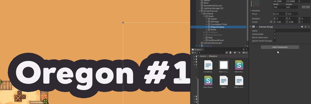
How??
Funny shader editing
To all use the same stencil, comp notequal and some other settings
It Works for my use case. I might publish a Gist of the shader since I’ve seen this same question asked in a few places and repeatedly left unanswered
It ruined anti aliasing though
Hi, still not sure how Discord works, and/or if this is the right place to ask, but I have a high level shader/ shader graph question:
In I use a "default" URP/Lit material, I get properties for a normal map, metallic map, occlusion, etc. If I create my own shader graph for some effect, is there an easy way to "layer" it with the default Lit shader properties? Other than adding new texture properties and reimplementing the other behaviours?
Basically what's the standard way to "compose" effect to avoid duplicating code/shaders?
I made this shader to directly negate fog. this works in editor, but in build its not working at all, Anyone know why?

How is it meant to work? Doesn't look all that different from how Lit materials act normally
By "not working at all", do you mean it fails at its anti-fog mission or fails to show up at all?
Mainly the boolean keywords, to negate fog. this works in editor, but not in a build
Editor:

Build:

https://danielilett.com/2021-05-20-every-shader-graph-node/
A Boolean keyword is either true or false, so using one will result in two shader variants. Depending on the Definition, the shader acts differently: Shader Feature will strip any unused shader variants at compile time, thus removing them; Multi Compile will always build all variants; and Predefined can be used when the current Render Pipeline has already defined the keyword, so it doesn’t get redefined in the generated shader code. That might otherwise cause a shader error.
Sounds like something related to shader variant stripping
I did set multicompile

Though I'm really not familiar with it
You and me both haha
Not sure about this keyword method, but for removing fog I've used a Custom Function : https://www.cyanilux.com/faq/#sg-lit-fog
mmm, lets give it a shot!
and then i'd route the outs of the sample Textures, through the custom function?

Should just need to be on one of them, but yes! The function itself isn't doing anything to the output, it's just required to define that MixFog macro - which "replaces" the MixFog() function call later in URP's code
Gotcha, i'll try it out!
Works perfectly Cyan, thank you 🙂
With custom render textures, is there a way to sample _CameraDepthTexture/_CameradDepthNormalsTexture?
I tried seeing if
return tex2D(_CameraDepthNormalsTexture, IN.localTexcoord.xy);
would work, but I just get grey .
How do you bring up the "add node" interface via keyboard?
I've tried everything under the sun that I can think of and nothing works
Surely I'm not expected to right-click, "Add Node" every single time
That would be crazy! 
oh looks like you can at least get it up by dragging off an existing node connector
idk if this channel is the right for this question
but is there a way to tell unity that there isnt a uv overlap where unity says there is?
these 2 are the exact same from blender to unity, and as you can see in blender, there isnt any uv overlap

Why do you think Unity's saying there's UV overlap? That would usually occur in lightmapping, which uses UV2. Is that UV2?
idk what uv2 is
The 2nd UV channel

i have no idea what to do
What don't you understand about the linked documentation?
I see overlap
lighter grey parts
i used the select overlay function in blender, didnt show me anything
I think the light gray is overlap tho
might be wrong
try pulling a corner of the light grey rectangle
does it have stuff under
it does not

looks like overlap
there isnt
there's another rectangle under?

ah
can you select that grey face and delete now I'm curious
what does it show
the only time I had that was when something was overlapping
cant delete any faces in uv unwrapping
deleted the face

🤔
after i fixed another uv overlap (made sure using unity uv overlap)
baked again and i got 1 more uv overlap now
11 before
12 now
anyway, im gonna head off now
why is the depth buffer (_CameraDepthTexture) always blank (completely black) when I try to access it in my postprocess shader despite the fact that Depth of Field postprocessing is working?
TEXTURE2D_SAMPLER2D(_CameraDepthTexture, sampler_CameraDepthTexture);```
it's just always a completely black texture
how do I get my hands on the source for the built in metallic shader
I would like to reference their math for supporting both a mask map and a functional slider for smoothness and metallic
In the unity github
yeah thats what I found, theyre just written in an incredibly distinct way from the way everything else teaches you to write shaders, I only care because I'm in an older version of unity
I guess Ill ask my main question: I want to support both a metallic map texture and a smoothness/metallic slider but have the texture take precedence, such that if the texture is present the slider information is disregarded, similar to how the standard shader works
non branching way to do this in psudeocode seems like metallic = metallicSlider * hasmetallictexture + metallic texture * hasmetallictexture
no clue the exact way to do this though
and unity shader source is very unclear for my beginner eyes
idk im a beginner too
but I'm guessing not having a metallic texture would just be a black color
and the black color would be replaced by a texture
if you do have a texture
i reccomend u follow catlikecoding tutorial
so you want metallic amount slider to work only if texture is present?
that pseudo code wont yield you this result.
pls make sure you have enabled using depth texture in the 1. renderer settings and 2. camera settings
predecessor?
\\do something
#else
\\do other thing
#endif```that is counted in static branching
but unity does that too
{
    #if GLOSSMAP
        return saturate(s.smoothness + (1-s.oneMinusReflectivity));
    #else
        return i.eyeVec.w;
    #endif
}```

Source
https://github.com/TwoTailsGames/Unity-Built-in-Shaders/blob/master/CGIncludes/UnityStandardCoreForwardSimple.cginc
GitHub
Unity Built in Shaders. Contribute to TwoTailsGames/Unity-Built-in-Shaders development by creating an account on GitHub.
Yes unity does that. Just that he asked what’s a non-branching way of doing it 😅
No, he asked the source for the built in metallic shader (which is actually integrated in the overly complex standard shader system), the non branching is most likely a guess or a suggestion.
ohh okay, sorry. I thought he was asking for a non-branching way. The source code in urp is available in the Packages/UniversalRP/ folder
actually, that's just my guess too 😅 I've might just misinterpreted it as well
He has a lot to read when he's back at work though 😄
While writing a custom renderer feature, how do I make sure to draw an object with a second shader pass index and not with first pass index? I am not overriding the material.
I was able to render using light mode tag. But I guess there should be a way to set the current materials pass index. Or access the current material / shader that’s rendering the renderer
Hello,
I am having an issue with my low poly water shader.
Whenever I put the Position into the Tile and Offset's UV (https://gyazo.com/4810c52a2ded521415e58ec0f8dad0b4) it does this: https://gyazo.com/41cf96ddb5f813dd6277b3bc75e0bb0a
It should look like this: https://gyazo.com/56fef068db50c74c9884cfabfa40a4f6.


I think you are putting the position in the UV not in the Tiling
also there are 2 position nodes, I am assuming you are talking about the one that is in the bottom left of the screen right?
Can I create shader in shadergraphy like mobile simple shader?
Yes.
so 2 things. You need to remove the position node from the UV node of the Tiling and Offset node.
rather you should change the position from world to screen space. I am sure you want screen space uvs and not world space uvs if you want to put them into the UV channel of the Tiling and Offet
try that first.
Using the Screen Position node?
yeah
I don't think that is what I am looking for. What I am trying to do it have the water tiled so I can have multiple water chunks. That is why I used the Position node.
oh sorry... then you need to remove the world pos from the uv. and put it into the tiling...
It still has the same result.
It also seems when I put the position into the Tiling and offset node it changes to a Sphere.


Graph looks fine here - though unsure about the "Wave Direction" property naming/usage.
You might just need to adjust the scaling, strength and height properties to get the result you want

Looks a bit bugged. But at a guess it might be that the graph has no Target (under Graph Settings tab of Graph Inspector)

target is not added
The graph requires a target. Press the + icon under that list and add the render pipeline you are using
It is weird because when I change the scale of the gradient noise, the water doesn't change.
Can you copy code of this shader please?
Maybe close unity and reopen, seems bugged
How are you changing the scale? via the material?
Yes
Which property are you editing?
The scale of the gradient noise.
I got it to work, I messed around with the Gradient Noise scale.
how can I adjust the transparency in the vertex shader depending on the deviation of the normal, I calculate through the dot the value between the normal vector and the vector directed towards the camera


If the z_correct_index is the transparency value you want, you need to pass it from the vertex tot he fragment stage to change the opacity.
You can do this by, for example, storing it in the vertex color, or add an interpolator in the vertex to fragment data structure.
Also, note that the current calculation doesn't seem to take into account the modified normal from the displacement
Further than this, the normal is not modified at all apparently.
if i set color like this in vert function alpha is changed

to 0.6
You didn't also apply the vertex color in the fragment stage ?
But now, simply, you just have to assign this alpha value to the vertex color alpha channel, and it should be good.
The code above sets the alpha to 0.6 and it works. Except it doesn't work with the dot product of my normals. There always alpha is set to 0
Maybe the result value of the dot operation is negative ?
Or something before is incorrect ?
How can I debug shader?
Personally, I output values as readable unlit color
I want to debug my z_correct_index
can anyone gimme an example that we can use view dir to make fun uv offset effect in shader graph ?
I wanna google for it but don't know the terms to search
Parallax Offset Mapping
thank you, I'm doing this, is this good?

I just wanna add some juice to her eyes bright dot, but don't know how to

if they're just static like a texture map then they're not so fun to look at
Note that shadergraph already has node for parallax mapping
Is the "bright spot" already in the texture ?
You probably want the view direction to be in tangent space btw
Idk if it's working since the dots are smol. But thank you for your help!
Can you please give a small example?
Something like
o.color = fixed4(1,1,1, z_correct_index);
This works. how can i flatten the display of my mesh? to render it flat? in this case, I have a spline-generated mesh, I want to flatten its display and blur the edges


Error building Player: Shader error in 'EasyRoads3D/Terrain/ER Terrain Mesh Tesselation': maximum ps_5_0 sampler register index (16) exceeded at line 149 (on d3d11)
Line 149:
sampler2D _NormalMap, _greenNormalMap;
To many texture samplers
Why don't you generate a flat mesh to begin with then ?
and it will not be too expensive for the device? generate a flat mesh constantly to match my volumetric mesh
I have no idea of what you are doing or trying to do.
I was assuming you were generating a mesh from a spline once, and wanted it to look flat.
From what I see in the screenshots it looks like two cynlindrical shapes
So what's the solution?
Declare separated texture objects and share the sample states
I’ll tell you in more detail, I generate a cylindrical mesh along the spline through the so-called TubeGenerator component
I want to add a simple glow effect
The original cylinder will still be drawn, I just need to add a little blur around the edges along this cylinder as if it were a lightsaber
I refused post-processing, there was also an idea to generate a flat Line along the same points of the spline with a white texture that disappears at the edges, but I think all these methods will be very expensive for weak devices
You don't know how to solve it?
You didn't describe the problem at all
^
That's an error, not a problem description
So how can I describe an error more than that?
I know how to solve it, and I gave you the solution, and a doc link pointing on how to separate textures and samplers
I don't plan to learn about shaders.
This error came from a paid asset.
The fix is not a simple one liner, it would involve to have access to the full shader and modify it.
Then contact the asset developper
Well, hum, please delete this link
Why?
Your are now sharing source code of a paid asset
That's not the debate. EasyRoads3D is a paid asset, they put time and effort to make it and write the shaders, you don't have the right to share their source code out publicly
Do people create shaders visually or via code btw?
Please remove the link or I'll have to report your to moderators
ok
So how can I fix it then?
Both / Depends
Try to contact the asset dev
no
...
We can't generally know from just the error what it is you were you trying to do or what the expected result is
A lot of the times the error itself is not the root cause, or even related to the apparent issue
Nor is it anyone's responsibility here to fix assets you bought
So