#archived-shaders
1 messages · Page 22 of 1
I think you're right. It was just called "plane" but I didn't recognise it because it looks kinda strange in the preview.
Is it possible to make a glowing URP decal? I made a shader graph like this:

But when i put it to a decal project it doesn't slow up, even if i set the HDR color intensity to really high
Here's what it looks like

I can make it glow if i add a bloom filter to the camera, but then other random stuff (like roof tops) start blooming too:

fix rooftops blooming
glow is just bloom in some cases
in others it's baked into the texture and does not look half as good
You can increase both bloom threshold and your decal's emission intensity to make nothing else glow
I can't seem to do that. For example I make the HDR on my decal material to say 100 intensity (or 1000 or whatever), but the bloom threshold doesn't seem to pick that up
I can't find any threshold that would show the bloom for only this material
Use layers to make PP only affect objects on certain layers
Post processing layers are per camera, not per object
Right. Kinda forgot about it. But then maybe use several cameras?
threshold should work, are the rooftops perhaps too bright to begin with?
It's possible to use camera stacking and have post processing on only some of them
However, the image that gets post processed is from the whole stack at that point, so only layers above/after can be excluded from it
It might be possible to render and overlay only specific objects* entirely separately, but then you'd have to somehow also do compositing so that your bloom can spill over to transparent pixels
Which I've never seen an example of in URP
I don't see any option on the post processing settings to select which layers the filter will pick up?

Volume components use their gameobject layer, the cameras use Volume Mask (not vcams)
how can i compare 2 hues in hlsl?
specifically, im trying to check if the color of the light illuminating an object matches a specific color
Okay, so how can I change the transparency value of a material? The material uses a shader graph that looks like this:

for some reaonsn the color porperty only applies for RGB values but not the alpha valie
value
how can I change it so I can modify the alpha value at will
You would need to Split the colour property, and multiply it's A output with your current alpha value
hi people, how would i do a radial fill shader ?
i need something like this gif i've made:

i basically have a sprite that's indicating the range of a effect, and this fill will say when the effect is gonna occur
what's the node i can use to do this fill effect and the one to "merge" the textures ?
if you always want it to fill from the center, you can do distance(UV.rg - 0.5) < fillRadius ? fillColor : emptyColor
and then have the empty color be the texture color perhaps
thanks, i've managed to solve it by doing this:

however now my shader works on the shader graph preview window but not on the game itself 

nice, that makes sense. Btw you can put a float into a float2 slot, it automatically converts it into a float2 with both components the original float
It might be something to do with not rendering areas it thinks will be transparent that actually do end up with color
Though I'm not entirely sure
uhh, and how do i do that?
anyone?
wdym multiply it's A output with your current alpha value?
What current alpha value?
the one from the branch node?
Hi, I'm making my own compute shader but when I render the image on something it has this blurry effect next to it. How can I disbale that?

Yes, what you have currently going into the Alpha port is what I'm referring to, so the output of the Branch node.
Also Split and Multiply are nodes
so like this?

Yes, with that the alpha slider of the colour property should now be taken into account
Would also need to change graph type to Transparent under the Graph Settings if it isn't already
but now the fill property doesn't work
Hi, I'm using the toon shader from Unity at: https://docs.unity3d.com/Packages/com.unity.toonshader@0.8/manual/index.html.
I'm finding that when I'm a certain distance from some models, I get faces coloured in solid black. It gradually increases the further away I get. I havent changed LOD model either.


Does anyone know why this happens? It only happens on a couple of models with really flat faces, it works a charm with everything else
Hey, does anyone know how to get the neighboring pixel of a pixel within the vertex and/or fragment shader? At the moment I am doing the following within the vertex shader
OUT.uv[i] = IN.uv + float2(_Offset[i], 0) * _MainTex_TexelSize.xy;
where _Offset holds a number like -2 (meaning pixel to times to the left of current pixel). (This is only for the horizontal axis)
I am not sure though if this is working :/
hey guys is any one have an idea for a good book to learn shaders and imageeffects for 2d games
like pixel art games
hey guys, does anyone have a custom node for URP that works with main and also spotlights?
If you read in a vertex shader, you must use tex2Dlod because it needs an lod level passed because ddx/ddy for the pixels don't happen until after rasterization (post vertex stage).
To read any textel in a texture you can take the width and height of the texture and compute the per-textel uv amounts....eg for a 600x500 texture it would be 1/600th and 1/500th. You can then calc the uv for your pixel via offset from current uv.
So, can anyone help? The issue lies in the fact that I also use a fill value which directly uses the alpha property
Oh, that makes sense, thank you!
And just to clarify, if I were to use tex2D(_MainTex,IN.uv + float2(_Offset[i], 0) * _MainTex_TexelSize.xy;) in the fragment shader that would work as I intend right?
Hello, I have a material and I want to change my Shader to: Standart Render Pipline
But seems like I don't have the option there look

The render pipeline is not a shader
There are a suite of default shaders for each render pipeline, but you find those throughout the various options
but in tutorial the guy have it like this

Search for 'lit' and there should be the option
also if you just create a new material, i think by default it's lit for whatever render pipeline you're using
those are categories

...
you did not set it up properly, look for a full conversion tutorial
(you have to create urp settings assets and assign them as render pipeline and whatnot)
yes

unity noob here. I'm used to creating materials using nodes. I have textures that I need to apply a HSV to. surely this is possible?
i just need to lower the saturation and bump the value on a few image textures
anyone?
Yes, that's where tex2D is usually done/used. As to work as intended, it looks like it, depending on your values for offset.
That is good to know, because that means I have to search for my error somewhere else. Thank you!
Hi, I need help. My shader displaces a different position depending on where the object is rotated in the game. If I'm facing a certain direction it will be displaced to the left, another it will be to the right. This is on a line renderer

Example of the offset, the one on the top is always in a different offset position then the normal material at the bottom

When I'm facing another direction

I want it to only displace the verts but it's displacing them all to the left/right for some reason, obviously it's a issue with the position ndoe but can't find anyone else having that problem
You don't really want to use the Contrast node here.
The Gradient Noise returns a value between 0 and 1 roughly, so first Subtract 0.5 to make sure it's centred (-0.5 to 0.5 range). Then Multiply by a value (e.g. 0.1) to adjust the strength of the displacement.
Thank you so much!
Hey, does anyone have any resources they could point me to that would help me understand how the Quest Guardian drawing is handled. I want to use something similar where I paint on the floor using a raycast. I am assuminug this is some sort of shader that reveals where drawn ?

Hello everyone, third time's the charm I guess. Basically I have a shader graph which allows you to set the fill value of a flask - AKA should the substance in it constitute 60% of it's volume or 25%? That fill property is handled by a remap node which, as it just happens, uses the alpha value. So how can I change the transparency of the substance without affecting it's fill value? Thanks in advance. The shader graph in question:

Line renderer could also work, there are many ways. You can find some on YouTube
Multiply the result of the branch by something
Also you can use a step instead of comparison -> branch, I think it compiles to identical results but it saves a node in the graph and looks neater
Using the line renderer sort gets me there. I am struggling with using those points to generate a mesh at the end like it does
See here for some...uh...discussion about _MainTex_TextelSize. https://forum.unity.com/threads/_maintex_texelsize-whats-the-meaning.110278/
Just an FYI.
Also remember that you can debug things in shaders by outputting remapped values as a color to "see" what is going on, just remap and plug into albedo.
Unity Forum
uniform float4 _MainTex_TexelSize
where is the value of the float4 _MainTexelSize from?
Hello! Is there any way to reference the total height/width of the surface to which my shader is projecting to?
What I'd like to do is have a tiling grid that shows the same uniform scale regardless of the dimensions of the surface that it is drawn on. You can see from the aliasing that my lines aren't drawn to the correct scale. The shader needs to appear transparent where the grid lines aren't drawn - that map in the background is showing through but is unrelated to the shader. This is for use in a custom editor window.
Also, the grid lines appear blue in the window editor regardless of the colour chosen in the material inspector - I'm not sure why this is and it hadn't been happening earlier.
Thank you in advance to anyone who might check this out!


I have actually seen this post already , it is very helpful, but also why I am confused about my program making things translucent instead of blurring them
The debugging part I always forget, thanks!
Edit: Found the mistake, one should not assign int buffers in the script part and then declare it as float buffers in the shader
Can you just use world space coordinates?
Hello! I would like to make a flashlight that reveals texture in hdrp i tried everything but nothing works. Can somebody help please?
You mean you want a material that displays one texture if the light is not on it and another if it is? If so, look into the stencil buffer.
Hi, does anyone know how can one access a value a node is outputting through c#? I want to access the "offset" value here

Hey y'all, i got an issue with shader graph, the preview of it works but it doesn't show that preview in the scene. I think a lot of people brought this issue up, but no matter where I look, I can't seem to have any of the solutions work for me. Can anyone help me with this? thank you in advance!


yes but i have no idea how to make stencil buffer
Preview node
The result is likely different for each vertex or fragment, so there fundamentally is no one value you could access
To the best of my knowledge to do that you'd have to render the result to a texture, then read the texture's pixels in C#
But you almost certainly don't want to do that
Heya, i recently found this shader: https://github.com/przemyslawzaworski/Unity3D-CG-programming/blob/master/fire.shader and wanted to make it so it doesnt have to blit the outcome and is actually applied to the mesh the material is on (you have to attach this script to main camera for it to work https://github.com/przemyslawzaworski/Unity3D-CG-programming/blob/master/fire.cs). I'm kinda stuck as I'm not really shader person, especially the GLSL ones so any point where to start would be awesome. Thanks in advance

GitHub
Various shaders. . Contribute to przemyslawzaworski/Unity3D-CG-programming development by creating an account on GitHub.
by what if I may ask? Sorry I didn't answer. I probably went to bed by the time you posted this
or just didnt notice
Whatever opacity you want
I might have turned off the ping by habit
so by alpha value from the color property?
once it's split?
Yeah that works
but here's the thing
hold on let me record it
the fill value doesn't work
let me show how it should look
*work
the fill value
oh wait
ok my bad
I just didnt notice somethin
Thanks though
yes
and now that I set it from transparent to opaque neither the transparency nor the fill value works
is it because you cant change the transparency of an opaque object?
indeed
you can use alpha clip
Is there a way to make a transparent object, well, not transparent?
if you set the alpha to 1, it acts like an opaque object (almost)
If you have it write to depth it will still block things behind it
but it's just A/B the whole thing will write to depth not just the opaque part
I mean the issue is that the substances can be either translucent or opaque
so uh
idk
but it looks the same if you set the alpha value to 255, right?
you can end up with sorting issues in particular around the edges because there are multiple valid faces to draw, and depending on the pipeline settings shadows may not be applied to transparent shaders, but outside of that a transparent with full alpha using the PBR lit graph should look the same as a non-transparent version of the graph
To get around sorting with other transparent elements you may also want to bump up it's sorting order to later or earlier in the queue
Wdym?
like
no matter the alpha clip
it looks the same
with alpha at full
because as far as im concerned you cant switch the shader graph setting from transparent to opaque and vice versa via code, correct?
If you have alpha fading smoothly, changing the alpha clip will change the point at which it transitions from opaque to transparent
yea but the alpha setting will stay the same after that
so
it's not a big deal for me really
I don't think so, unless you count swapping the material or setting alpha to 1
swapping the material is hugely inefficient though isn't it?
Probably, I'm sure you don't want to be doing it regularly
which, in case of instantiating a new game object, would be hugely inefficient to keep on swapping it
Unless there isnt a shader assigned in the first place and then it would be assigned by code?
I don't know
what are your thoughts?
i'm going to sleep. Mind pinging me with your answer later? Cheers
Hey y’all, I’m still trying to figure this out. Anyone knows what the issue is?
I’ve noticed something though. When I set the material to be sprite lit, the preview is identical to how it shows in the game
When I set it to unlit (which is what I want) the preview becomes white as shown in the screenshot. I believe this has to do with the 2D renderer, no?
hi, someone help me pls, how can i use blending mode in unity? m use 2021.3 vers
BiRP, HDRP or URP?
HLSL or Shadergraph?
i dont know, i m newbie, but i need to blend 2 layer of UI to got true color designed, im a designer not a dev, but our dev don't know it too, do u have a tutorial?
i saw some tut on utube, they use shader but i can't find that https://www.youtube.com/watch?v=oPNXDaNfls4

This shader can create all photoshop blend mode effects on the applied renderer. Just like photoshop blending with every layer below, this shader blends with everything behind the renderer with this shader. If you want this, just comment.
#unity #photoshop #blend #shaders #shader #unity3d #gamedev #oyun #oyungeliştirme #visualeffects
That's ok, it's hard to figure out the problem without the extra context but happy to still, try, I'm not too experienced with UI things. That video looks like it is showing a custom shader/material that you would need to get that to work
yeb, i think that need a shader to blend, but dont know how to creat it, so i ask for help, anw, thank you for aws :>
Shader Graph has a node Blend that has pretty much the same options as photoshop blending modes
Yeah you could set it up so that the shader samples the scene color then blends the element as needed, the problem is you could only do it with one layer
yeb, i found that, but still can not get blend with a sprite sheet :< , so i think i need to creat sprite sheet in shader too, but i cant find that note like this tut https://youtu.be/Mn3veUb4hA0?t=318

Help to support the channel if you are feeling super kind: https://www.patreon.com/dapperdino
Join our Discord: https://discord.gg/sn9xXK4
Here is the example project created by Unity: https://github.com/UnityTechnologies/ShaderGraph_ExampleLibrary
In this video I show you how to create shaders for 2D sprites and we make a simple colour gradi...
If you aren't using the 2D shader graph I believe you use texture 2D Array to access sprite sheets
If you want to set up something more flexible you could check out this: https://elringus.me/blend-modes-in-unity/
ok, i will try, thank you
Is there a reason Graphics.DrawProceduralIndirectNow() does not working in the update() method? It only works in the OnRender() method.
Because that's when unity sets up the GPU state and collects the command buffers I guess.
Command buffers need to be cleared before the new frame rendering starts. So if you queue commands outside of that timeframe, they're just removed without being processed.
Sorry for the late response (wasn't around anymore) - does world space really work in an editorwindow? Edit: I'll test this soon.
if you want to call a compute shader once per frame do you just call its dispatch method once per frame or is there a better way to do it?
for some reason whenever i try and run my VR project these flood of errors comes up, im not sure why hdrp wouldnt be supported by my GPU since its a RTX 3070, any idea as to why this happens and how to fix?

not sure if this helps, but its a laptop
same error on main desktop with has a 3080

i did briefly, both GPUs support DirectX 11 and DirectX 12,
Did you apply the mentioned project settings?
the "single-pass after startup" ?
This
To use Virtual Reality (VR) in the High Definition Render Pipeline (HDRP), you must enable VR in your Unity Project. To do this, see the VR tab in the Render Pipeline Wizard.

Please refer to Unity XR documentation for more information about XR developement with Unity.
i believe so? Let me double check.
yeah, HDRP + VR
should this be of any concern?

It tells you to confirm these things manually.
alright, i probably should do that, couple red errors came up and i just clicked "fix all"
alright i have manually changed them
it didnt take me 15 mins, i was doin some else
fun...................

I guess you can't replace UNITY_SAMPLE_TEX2DARRAY with something similar in compute shaders??
i'm using SampleLevel now but the UNITY_SAMPLE lets you use a number for the texture index
can you get the depth of a 3D texture somehow? _TexelSize doesn't fit that at least
this is all flowing completely through my head lol, i couple months into using unity and this is the first issue that i couldnt fix myself
It also wont really read what i expect it to from the Texture2DArray with SampleLevel. It's like it's just reading from the first array index or something.
no this is my issue 😂
sorry i have no idea whats happening for you
yeah its so weird, works perfectly fine in unity, cannot export it though
Hi guys
Any recommendations for books for learning image effect shaders for 2d games
UNITY_DECLARE_TEX2DARRAY seems impossible to use in a compute shader even with #include "UnityCG.cginc". Idk maybe I should just write a 3D texture as an array...
Alright I figued it out mostly. I changed it to a Texture3D and simpy sampled that with .SampleLevel, but even so it was a battle because I ended up having to declare Texture3D<half4> texture; Could someone kindly enlighten me what the big difference is between a frag shader and compute shader when it comes to texture declarations, because I don't really understand why I had to make this distinction in the compute shader?
Heya, I have a really basic understanding of compute shaders, and I was wondering if anyone could give me advice/point me in the write direction to rendering graphs based on values like in this video:
https://www.youtube.com/watch?v=hfMk-kjRv4c
You can see the effect I want from 14:43-14:09, and I know for sure this is done with a compute shader.

Exploring how neural networks learn by programming one from scratch in C#, and then attempting to teach it to recognize various doodles and images.
Source code: https://github.com/SebLague/Neural-Network-Experiments
Demo: https://sebastian.itch.io/neural-network-experiment
If you'd like to support me in creating more videos (and get early acce...
The only other thing I know about the method he uses this code. I assume here that graph references the compute shader.

I'm unsure how this method is being called, and given that this would have to be run for every pixel, and that this is c#, i'm not sure how this would be performance efficient either.
Hello guys i have big problem, i was making water shader graph and it was colored, and i touched something and all went wrong, it is transparent and not i dont know what can i do please help me

can we se the graph you were working on / what you "touched"
^
Hi guys, I was looking for some shader outline tutorial in URP but seems like I can't find any decent tutorial about that. Every video/guide forces the object to have something that I really don't want to have because it complicates everything in my code (e.g. setting the object of which I want the outline applied in a specific layer, and many objects in my game have their own layer type, for example dropped items need a specific layer to phisically interact only with the terrain).
What I'd like to have is a simple shader graph scheme (maybe a subgraph?) so I can place it inside every shader graph I want to give my shaders a nice outline. Almost all my objects should have an outline, and almost all my objects use my custom toon shader or a variant adapted to the object needs.
Have you got any tutorial about that? Anything to help me?
Hi there! I've made a shader graph shader in hdrp, and I'm trying to get it to display in the game view, but it is just showing up as blue. The shader has a material witch is attached to a image on a screen space overlay canvas.

If you look up how to create an ocean shader, they often will start with how to create foam which uses edge detection
You can then just copy off that and fix it to your needs ig
I did that, I also did foam in my water, but how that works is by "cutting" a part of the mesh, and my meshes are already very thin
It's more an "inline" than an "outline" 😛
there seems to be a bug with HDRP and shadergraph shaders for UI
it should work if you use screen space camera mode for the canvas
ok thanks
mmm
something definenatly changed
but the transperancy still doesn't work properly
waitt i have an idea
yep!
working now thanks @knotty juniper
Set it to point sampling
Should be an option in the texture's inspector. Ugh, opening unity takes forever

It's default bilinear so just select point then press apply at the bottom right
Select the texture asset in the project explorer within unity.
Yep, the textures. Click on it and look at the inspector window.
What do you see in the inspector?
huh, why do you have the debug menu open?
Press Ctrl-3.
Ha, nice.

I've never touched shaders before. Would it be the thing that I'd use to accomplish the sheen on this rocket? Or is that more of a material thing
Materials are driven by shaders, so yes and yes.
Sheen? The lighting? Definitely possible right out of the box (HDRP probably). The lens flare will take some tweaking but also possible.
The retro style will probably need a fullscreen post processing pass. Which will be difficult to perfect but also possible. A lot of work though.
What about it would require HDRP? I feel like I could sort of "fake it"(?) and not worry about incredible accuracy since it's pretty stylized right?
Just as long as it gets like a similar result?
Of course you can fake it. That means doing it manually. I recommended HDRP because a lot of the fancy lighting comes out of the box and is robust. If you want to use something like URP or built in, reinventing the wheel will mean better performance and flexibility but expect months to even years to get the look you want. Even with HDRP, it'll probably take months to get the retro filter looking right anyways.
I'm creating a project now - can I switch to using HDRP even if I started with a normal 3D template?
Yea, just install the high definition rendering pipeline package. It'll take a while and you'll need to spend time converting everything to HDRP supported shaders if you have pre-existing materials.
How does URP fit in all of this? What are its advantages?
Sorry, I know these are pretty broad/basic questions
Yea, those are very high level questions. Google will answer that far better than I can.
Basically, HDRP for the AAA visuals and URP for a clean slate. HDRP comes with a lot of baggage that weigh down performance, even if you're not using any of them, but URP comes with very little features and the ones that do come with it are pretty bad TBF.
How would I go about rendering an object whose mesh is calculated in a compute shader straight on the GPU without having to read the data back onto the CPU? I see Graphics.DrawProcedural , but wouldn't I have to set up the MeshTopology on the CPU with the verts/normals/etc that were calculated on the GPU? https://docs.unity3d.com/ScriptReference/Graphics.DrawProcedural.html

Oh boy, are you ready to jump into the rabbit hole of SRP?
Are you using HDRP or URP?
I'm not a big fan of using a ton of out-of-the-box stuff, so I'll probably opt for URP. Thank you for the insight
Yes! URP. And for this example, lets say I want to just draw a unit cube (whose verts/etc are calculated in a shader) and just pass the position to the GPU. Something like DrawCubeGPU(new Vector3(0,0,0))
You say that now but trust me, reinventing the wheel is a great educational opportunity but it will take months, if not years, to get good at rolling your own. It's that bell curve meme where the text goes HDRP - URP - HDRP.
But it doesn't seem like it's just a matter of DIY vs not, as from what I've seen online, HDRP is virtually unusable on systems that aren't state-of-the-art
(correct me if I'm wrong)
Ehhhh, a lot of the really high end features like raytracing need top end comps but basic lighting is far superior in HDRP than URP simply for the additional parameters.
Ah I see
I think what I'm looking for is something like a RenderTexture, but for a mesh instead
Do you know what a rendering feature is?
Yea, I know what you want (probably). I do a lot of GPU driven procedural rendering for my graphics.
I haven't messed with rendering features yet
You can make a room look near photo realistic with decent performance (60fps) on a midrange computer ($800 laptop) with HDRP. URP in the same room with URP lighting will look like garbage but you'll have 120 fps.
Custom rendering features are how you insert GPU operations into each frame. You get access to a graphics command buffer that you queue up draw calls and compute shader dispatches.
For example, this is how I setup and queue 2 draw procedural calls for my custom 2D lighting rendering system.

Thanks! I will look into this
And this is how the whole lighting system comes out to be per frame (using the frame debugger). 8 draw calls in sequence.

You can insert your compute shader into this sequence using the command buffer dispatch compute method as well and it just slides into the stack as a command. Then use the results of that compute shader to render a mesh using draw procedural indirect probably.
The main issue of course is hooking up built in lighting which will be very difficult. Wish ya much luck in that.
Just want to say that it's possible in all render pipelines, be it built in, urp, or hdrp. But most likely, any pipeline you choose won't give the wanted result out of the box. You'll most likely need to setup/write your own shader. That, or you simply 'bake' the look into the texture
what are the best kind of shaders to use with sprites?? there is lit and unlit and other ones.. can someone help
theres not "best", lit gets affected by lighting and unlit doesn't, unlit just displays the color as it is no matter the lighting
ah thank you
can you tell me a bit more about custom lit shader?
for sprites you should actually use the sprite lit and sprite unlit, the lit and unlit ones are meant for 3d
i meant sprite lit and sprite unlit... sorry
i do have another question ..., in this pictuer is there a way to make the black part of the picture invisible??
(i made it like this using the shader graph)

lit shader is a shader that gets affected by the lights on the scene. with custom shader you can make custom effects that changes the color of sprite, emission etc.
just use the alpha block to change the alpha and probably alpha clipping too
I am sorry I dont understand what this means
in the shader graph where you have things like the main color, position etc. there should also be a alpha block you can use to change the alpha (transparency) right?
yes
how do i make it change ONLY THE BLACK SPOT TO BE UNSEEN

how do I take the black part alone is my problem... the closes I got is to make the graph settings "additive" so the black part doesn't contribute in anything but now the look of the sprite is bad
I am using a step node so it makes some black and some white... that is where the problem begins
Go to that page you linked, click on the MeshTopology link....it's just the TYPE of mesh, not the verts. The verts are going to be in a compute buffer set up on the GPU.
basically add each pixel r, g, and b and input it to the step node, and use very small number for the other step input, then use the step output to multiply the alpha
OH I will try i
it*
Hello everyone !
I'm not a shader pro, I have written a few fragment and vertex shaders here and there, have a basic understanding of stencil pass, but that's it.
I'm currently working on a 2D game and I was wondering how I could manage to replicate effects from photoshop layers. Basically, something like that :
Final color = f(sprite1color, sprite2color).
I knew that shader passes somehow allow to make some blend combinations but it feels very limited.
Do you know of any resources I could study that would expend unity's URP to allow me to do this?

it isn't working because the input to the set node comes from a polar coordinates (only the g)
OH IT WORKED
now I got it ... thank you
It's "just math". The blend operations with the blend command work on passes, as you state, but you don't have to do it that way. Not quite sure of your use-case, but if you have both "layers" available to you in the same pass, you can "just do the math" of them manually.
For example, a standard transparency would be computed as:
float4 resultColor = float4(foreColor.rgb * foreColor.a + backColor.rgb * (1-foreColor.a), 1);
See the blend command documentation, and decode the maths. In the end, it's a float4 (or half4) vector rgba. It's all math.
Thanks for your answer.
The math part is not really the problem. What I would like to understand, is how to have those 2 layers accessible in the same pass.
Let's say I have this shader 1, that is used on sprites from the layer 1.
Then this shader 2, that for example would be the a soft light that would apply the blend formula on these sprites in layer 1.
How, from this Shader 2, can I access the color of those layer 1 sprites?
You'd have to have them in render textures. But you'd have some kind or "result/composite" layer result you're building up as you net it all out.
GTG now, but I'm sure others will have ideas too. 🙂 Good luck with this.
Thx I'll have a look at these
https://elringus.me/blend-modes-in-unity/
Found an interesting article. Never heard about GrabPass
Elringus
You’ve probably heard about blend modes available in image and video editing tools like Photoshop or After Effects. It is an important technique for content creation and has long since become an integral part of them.
nvm grabpass is very heavy.
I'm gonna look at render textures
heavy / expensive is relative
its faster then rerendering the whole scene into a rendertexture and using that in your shadr if that is what you would use it for
you just have to make sure not to overuse it erverywhere
From my understanding of different threads I just read, grabpass is using a rendertexture behind the scenes anyway
that could well be it has to get the texture data of that is currenty renderd somehow and rendertexture seem the right way
the difference it how you fill the rendertexture
Yeah. Although in my case I think there is a little struggle with the render texture :
I want to blend only with specific objects, let's call them "Lit". But those Lit objects could be hidden by "Unlit" ones. Will I be able to create a render texture that takes this masking into account?
the rendertexture is super dumb it does not knows anything about your scene
maybe a better way would be to use the stancel buffer
https://www.youtube.com/watch?v=-NB2TR8IjE8

Tutorial going over the core concepts and syntax for using the stencil buffer in Unity shaders.
Here is the full reference: https://docs.unity3d.com/Manual/SL-Stencil.html
(all depending on your scene and use case)
then you can write into the stancel buffer with the unlit materials and in the lit materials you check if the stancel mask is 0 and only then render the pixel
That's interesting.
I'd have one buffer exclusively for the unlit that would create the main texture
I'd have another one for the lit ones, where they would write only if they are not masked, to create a secondary render texture.
Then I'd apply my blend effects on the render texture and overlay it on top of the main texture for the final result
hello! quick shader maths question
when we transform a position from view space to clip space (ndc), we have to do a perspective divide, yeah?
well if we do it backwards
from ndc to view space using the inverse projection matrix
do we also have to do a perspective divide?
seems so
Hello! I'm using unity 2022.1.3f1 and URP. I need to outline most of the objects in my scene.
After many hours of research for exactly what I want to do I gave up and tried to follow the tutorial that seemed to be the closest to my goal: https://www.youtube.com/watch?v=RMt6DcaMxcE&list=PLAUha41PUKAaYVYT7QwxOtiUllckLZrir&index=4
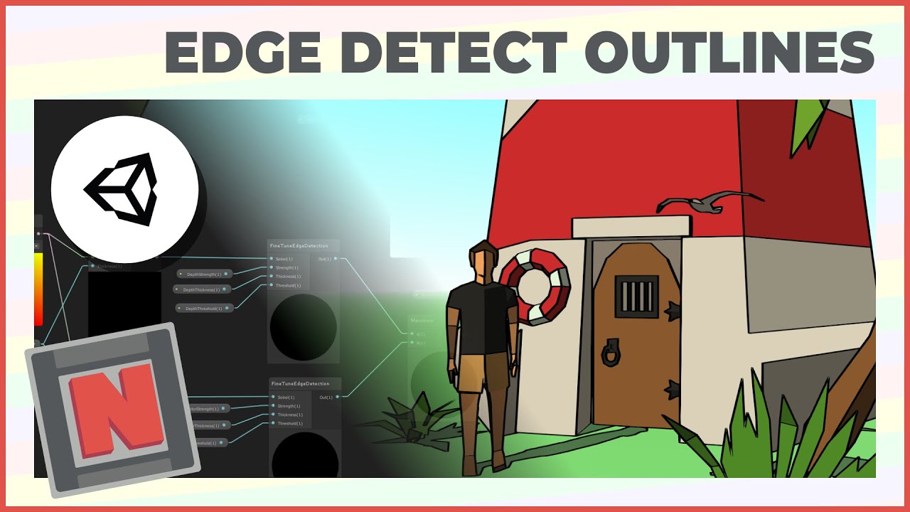
✔️ Works in 2020.1 ➕ 2020.2 ➕ 2020.3
🩹 Fixes
► I made an editing mistake around 1:30. Please note, you need to place the outline material into the material field of the BlitMaterialFeature. It should not be empty after this step. Sorry about that!
► At line 35 in EdgeDetectionOutlinesInclude.hlsl, the sixth entry in sobelSamplePoints should be f...
Sadly, it doesn't work and I don't know why!
First of all, it broke my editor:
As you can see from the screen, if I'm in the scene window, the game and shader window buttons are behind a random gray square

(if I blind-click the game, it gets back to normal, but when I go in the scene the gray area returns)

The gray area is also the same color of the material that I'm trying to apply the outline, so that's really weird
Second, the outline seems to work in the material preview, that is for some reason in a random square at left of the "Add Component" button. I can edit otuline values in the material, and the outline in this weird preview actually works.

But it doesn't work on scene, it doesn't matter what I do.
Any clue on why that's happening?
That's my renderer, as it is in the tutorial:

Depth texture is on
When working in hlsl, how can you easily go to the definition of a function? Is there some IDE or tool that would allow that even if the function is declared in another file?
I can't think of a way to do it via shader, unless you provide the terrain heights data into via a buffer or a texture.
I think it's more common to modify the indicator mesh instead.🤔
how to make a shader overlay on top of the base texture? I have a tilemap and want to preserve all tiles' looks, but shadergraph completely overwrites them
Has anyone used Shader Graph + URP to follow Sirhaian's VFX tutorials? I'm having some difficulties setting up the shader to work with Color Over Lifetime.
You guys have any tools/plugins that help you write shader code? Anything to get intellisense or something similar?
I don't know the ones you refer to, but Particle System uses vertex color for particle coloring, which you can access in SG
For monocolor overlays per tile, I've just been drawing a transparent texture over the entire map and a pixel per tile.
I do have a vertex color node set up, and the RGB values of Color Over Lifetime apply, but Color Over Lifetime's alpha values aren't applying to the effect. I do have my alpha input hooked up.
I'm sorry that my Shader Graph is kind of hacked together, the tutorial I'm trying to follow was originally made in Shader Forge so I'm trying to match a lot of things using context instead of function.

Plugging a Vector4 into a float probably only uses the first channel as the output
Try getting the alpha with Split
And I would be trying to pull the alpha from the Vertex Color?
Yes also
Ok, so I've split the alpha channel from vertex color and plugged it into my alpha input, but now that disregards the alpha information in my texture

Use what you originally had but split out alpha right before the output
Something like this?

The artifacting around the effect is what results when I split the alpha
Make sure your particle texture's background is fully transparent, and that transparency mode in graph settings is not "premultiply"
It's additive, and the textures I'm using have backgrounds with 1,1,1 value. They are .tga 24-bits / pixel, if that makes any difference.
Interesting, changing the graph settings to unlit removed the artifacting
does anyone know how i can get a texture to do this? (like scroll i guess in a drection)
UV.x += time.x * modifier;
im new to shaders, do i put like this script on my object and assign the ui.x
Shadergraph or manual?
ok thanks
You need to make a material that is applied onto the object mesh. Within that material, using either ShaderGraph or ShaderLab, increment the UV in the direction that you want the texture to move in as a function of time in the vertex shader. Very simple concept, difficult to begin if you're new to shaders. Wish ya much luck.
Is there a way to sample the realtime shadowmap in shader graph for HDRP?
Ah, thanks. Silly me...
When people saw "limit draw calls" do they mean any draw call, or only when a mesh is being uploaded to the gpu? If you use a buffer that is already on the gpu, are draw calls still bad?
a draw call is the CPU telling the GPU that it should render something
the less you have of them the less limited is your rendering by your CPU
URP and HDRP have the SRP batcher
that shold combine most materials together so that the drawcalls are not the big issue anymore
It's not the uploading that is the problem. I'm not sure about meshes, but for example textures are only uploaded to the GPU memory once. It's all kind of low level GPU state changes that take time. If you keep on rendering the same material, there's no need to change these states, but the more different materials you use, the more of these states need to change every draw call causing longer processing time.
One thing that I always wondered, do material variants each use a separate draw call?
It depends on many things. If they can be batched, then no.
But they don't instance together via gpu instancing?
Also depends on the render pipeline. As Malzbier mentioned, URP/HDRP are better at batching draw calls.
There's no magic that instances the materials automatically. Besides, instancing has some specific requirements for it to work.
I'll have to look into the frame debugger I suppose. I wonder how many draw calls you have to have for it to really be a problem these days.
tens, hundreds, thousands
Depends on the platform and the specific device. Besides, it's not like every draw call has exactly the same impact.
I'd say around 100-200 for mobile and maybe a 1000 for PC, but that's really rough. It also depends on how much budget you have for rendering. If all you do is rendering in your game, you can spend all the 16.6 on it to get 60 fps. If you're okay with 30 fps you have double that time.🤷♂️
Thanks, that's helpful. Was just thinking about where it fits on the priority stack without having dealt with it much in the past. CPU usage is something that's really important for my project, but up to now the biggest wins have been in script optimization
Yeah, usually rendering would take around 25-30% of your frame time budget, but again it really depends on the project.
Is it possible to take the output of a shader graph and save it as a new texture? Let's say i've got a complex shader to blend several normal maps together and want to create a new texture from the output, and use that texture in a simpler shader.
Id do that with handwritten compute shader (not shader graph)
You can use @regal stag BakeShader for that, -> https://github.com/Cyanilux/BakeShader
GitHub
Unity editor tool for baking shaders to textures. Blit2D, Blit3D, or MeshRenderer (uses model UV). Adds options to Material & MeshRenderer context menus and Editor Window (under Window/Cyan...
ooh didnt know about this, ill take a took, thanks!
i have no idea how to write this stuff sadly.
I think what you were seeing was reflected light being rendered on the transparent parts, which happens with additive and premultiply transparency
Would you say it's a good idea to slowly ween off of shader graph and just start coding shaders like normal?
Whats the difference between multiple shader passes and multiple shader variants?
I am currently working on a blue shader issue in an editorwindow, and similarly transparency doesn't produce the intended effect unless I enable alpha clipping. Can you share how you solved your blue texture issue?
If I can swap "visual behavior" by changing pass or by changing material to one with another shader variant, which method should be preffered?
As I understand it, it is best for performance to stick to one shader variant (for srp batcher) so using different passes seems best, but I have not seen anyone else do this.
I'm using CommandBuffer.DrawProcedural, but is the SRP batcher even affecting this call? Or does this bypass the SRP batcher?
Well, "draw calls" can be seen in the frame debugger. But it's more complicated than that.
The simple-number of "draw calls" is deceptive. The concerns are about two things, really:
- Don't draw things you don't have to (make everything efficient, best way practical).
- CONTEXT switches are much more costly than just draw calls. This is why various pipelines group draw calls by material and/or by shader.
Of course, to answer part of your question, having the data already on the GPU means less overhead to ship data "up" there. Which is why they/you do procedural geometry in the first place, otherwise you'd just ship it up every time.
In the end, "it's everything all at once that adds up". But, context switches are rough. And the old saying is "the fastest polygons are the ones you don't draw." The GPU is capable of doing millions of triangles per frame, 30+ frames per second. Hardware levels vary, of course.
TIPS: Making the shader and the entire process efficient is the goal. So be careful of taking one stat/number out of context. It's a whole package. Do as much in the vertex stage as you can practically do. Make the fragment stage as efficient as possible. Don't do things that you'll just have to write over later if you can avoid it. Use LOD in a common sense way (like only 1 or 2 levels beyond the main). Don't pass twice what you can do once. Vectorize calculations where possible, combine calcs into same pass where practical. Avoid read-back to the CPU. Group like-things (pipelines do this already, usually) to avoid context switches. Think about memory bandwidth on the GPU. Avoid dependent texture reads if you can (google it). Use the engine as it is designed where possible, it's pretty optimized, fighting it is often a mistake. Align compute buffer data on float4 boundaries (GPUs like that). Keep vert2frag data as low as practical to save interpolators. Reuse variables to reduce vector register pressure in the frag stage (the optimizer may help with this though, so not really sure on this one).
@meager pelican your mention of dependent texture reads send me down a rabbit hole of reading. But if we can trust the wise word of bgolus on the forums on modern hardware uv modification in the fragment stage is okey
Also doing "as much as possible" in vertex stage is not always good advice. If you do something like shift or rotate the uvs, it makes sense to do that in vertex stage but if that requires defining new interpolator, its most likely not worth it, its not free to interpolate the data from vertex to fragment stage
Thank you! Here is another scenario you may be able to shed light on. If im creating a procedural mesh but using box colliders instead of mesh colliders (cubic voxels), should i calculate the colliders in the compute shader as i mesh? Here is my setup:
- Voxels calculated with compute shader
- Mesh generated on gpu with voxel buffer
- Two options for colliders:
3a. Generate on gpu while meshing, pass back position and bounds of colliders to the cpu
3b. Pass voxel data to cpu, cpu generate colliders (separate thread for efficiency)
Why not just use a mesh collider?
Because is so much slower. Im making a chunk system and having a few box colliders per chunk would be a lot easier on the physics than a bunch of huge meshes
You can always trust bglous.
DTR's are more about reading one texture to get the result for reading ANOTHER texture after that. So the GPU can't parallelize it, since it has to wait for one result to go get the next result. It is a bottleneck.
@dim yoke Yeah, all depends. I mean, you can pack interpolators. And the general rule of thumb that I use is that if you can get away with four interpolators, that's fantastic. Don't remember where I dug that up though. It's all YMMV.
Did you actually test it? In my opinion there's not gonna be much difference. If anything there's a chance that the box colliders would be slower, since the physics will have to deal with more potential collisions.
In a random unity document, i learnt that batching is worse for mobile
specially for transparent objects
it sums up a whole bunch of overdraw
now the question is... if i make a single texture atlas...will there be reduction of drawcalls automatically? instead of using multiple textures?
Hello all! Some days have passed since I last posted here, and I still seem to be stuck trying to get a graphic to render correctly in an EditorWindow using a custom shader made in shader graph. What follows is my script to create two preview textures - one which contains a 2D world map which is used in the game and the second is a grid overlay that uses the same dimensions of the image beneath it.
    {
        DrawMapArea();
    }

private void DrawMapArea()
    {
        _scrollPosition = EditorGUILayout.BeginScrollView(_scrollPosition, true, true);
        EditorGUI.DrawPreviewTexture(new Rect(0, 0, _map.backgroundImage.width, _map.backgroundImage.height), _map.backgroundImage);
        EditorGUI.DrawPreviewTexture(new Rect(0, 0, _map.backgroundImage.width, _map.backgroundImage.height), _gridLinesTex, PrefabLoader.Instance.matMapEditorGrid);
        EditorGUILayout.EndScrollView();
    }```

1) First image shows the complete graph for this simple shader
2) Second image shows a solid blue colour which is the appearance of the preview texture when alpha clipping is disabled
3) Third image shows the graphic beneath the problem layer when the second call to `EditorGUI.DrawPreviewTexture` is commented out.
4) Fourth image shows the graphic rendering with alpha clipping enabled.  The shape is correct but the colour is still mysteriously blue.

I am using URP and the targets can be seen in the first image's graph properties.

Thanks to anyone who reads or can point me to what is happening here.


Just blit to a render texture using the first shader material and then use that RT as input to another shader in another blit.
ive never written shader code before, but ill look into it, thanks.
In my case, texture is not taking in the file I am trying to feed, are there other reasons or limitations?
Hi, everyone, I have an issue with the time node in the shader graph, the attribute Time doesn't work and I can't understand why, I use it like always. The others attribute works. Maybe the issue appears when I switch to the Android platform. Does it make sense to anyone?

need help with the parallax offset node, ive got a heightmap packed into the blue channel of this texture, how do i plug it into the height map? it wont let me, i tried combining the Blue channel into a vector 2 already

This node expects the height to be in the red channel iirc.
And you need to use a "Texture Object" node to connect into the heightmap input
is there a way i could use a swizzle node it then convert it into a texture object?
No
Sounds like a bug to me, the Time node should work on all platforms. Or maybe you're looking in the scene view out of play mode and the animated materials is disabled ?
hello everyone
so I was following this tutorial https://www.youtube.com/watch?v=tI3USKIbnh0
but for some reason the bottle isn't full, even though the fill value is on 1
I tried adding the same material to a 3D cube and it seemed to work, however after scaling it over a certain amount, I could see that it didn't fill the whole cube


Here's a basic Liquid simulation with Unity Shader Graph, an effect that fakes a fluid in a recipient. It uses world position, backface painting and a script to simulate a basic motion.
Wobble Script: https://www.patreon.com/posts/shader-graph-52529253
Enjoy!
Rabbit's Tale - STEAM WISHLIST: https://store.steampowered.com/app/1763860/Rabbits_T...
is length a stupid way to compare 2 floats in shaders? i'm checking texture sizes against a length(float2(1,1)) for example
length returns you the length of a 2/3/4 components vector.
If you want to compare floats, you use comparisons like A > B or others.
I probably didn't understand your issues 🤔
probably a simple issue but i guess i don't really understand a length. i was doing for example if (length(_MainTex_TexelSize.zw) != length(float2(1, 1)))
but idk if this is a bad idea
or if i should just do
_MainTex_TexelSize.z != 1 && _MainTex_TexelSize.w != 1
or if it doesn't matter
Oh, so you want to compare two float2 ?
With float imprecision, it can be risky to do A != B
But you can do this :
float2 diff = abs( A - B );
if (diff.x > 0.000001 || diff.y > 0.00001) ...
Comparing length is obviously not enough, as length(float2(3, 4)) is equal to length(float2(-4, 3)) even if the vector are very different
When using Graphics.DrawProcedural how do you set the render target to a RenderTexture? I have tried with RenderTexture.active = rt and var c = new CommandBuffer(); c.SetRenderTarget(rt); Graphics.ExecuteCommandBuffer(c); but it still renders to my camera.
hmm yea i guess maybe i should be doing it something like that @amber saffron i haven't had any issues with floats in the shader at least when it comes to checking vs texture sizes and so but. i think i figured out my problem tho, which was that I wasn't typing "f" after my 1's to turn them into floats.
converting my fragment shader to a compute shader has yielded plenty of secret issues that have been hard to find
I think you'd use RenderTexture.active or Graphics.SetRenderTarget, then Graphics.DrawProceduralNow.
Or CommandBuffer.SetRenderTarget and CommandBuffer.DrawProcedural then Graphics.ExecuteCommandBuffer
Ok I see, but for things like Graphics.RenderPrimitives they can not be used with rendertextures then? Since, I believe they don't have an equivalent in commandbuffers nor a "Now" version.
ah no nvm it just generated a syntax error that seemed to fix it 😂
I'm creating a 1x1 Texture2D with the color 0,0,0,0 and sending it to the compute shader yet it won't work to check against the texelsize. maybe the issue has been float precision this whole time i'll give that a try, but it wasn't an issue in the fragment shader
Or wait, Graphics.RenderPrimitives is basically same as Graphics.DrawProcedural.
All these variants are confusing 😆
I am not very experienced with shader graph. Can someone help me make a wave? I think that I can use the Noise Sine Wave node, but how do I map it to the material?
I am guessing that I will be needing the UV node
Off the top of my head, I don't remember all the nodes, but I'd be down to put one together quick.
Wow. That would be amazing'
Hey! I'm trying to just change the color of this Axe head to a different color. I'm not sure if it's an easy swap or if it's a lot more than that. But this is the texture that was attached to it. Any idea how I can just assign new colors from this texture? Thanks!


What render pipeline are you using?
URP
@sacred hull So when you say "wave", is this some kind of water shader?
No. Like a TV with no signal kind of. Just a plane with a wave "texture". I need it to move
_TexelSize isn't automatically allocated in compute shaders??
Just white noise?
No no. It needs to be a sine wave that I can scale
I also need it to be tilable, but I figured that would be pretty easy to add
Ahh, okay- not sure how I'd do that but I'll fiddle for a bit.
Ripple wave, I think.
Thank you 🙏

Yes, although it needs to be black at the top so that it becomes a white line
How did you achieve this?
Doing some bug testing.

Ayyyyy
Basically I'm exploiting multiplying the X and Y positions of an object's local space.
I'll explain it all once I know it works without bugs.
Thank you. That's great
No prob, had to figure this out for myself.
Okay, so this is going to take a little bit of trig, but not really.
@sacred hull


This section multiplies a Frequency float by 2π, which is the relationship between the radius of a circle and it's circumference. We need to tile by 2π in order to have the lines wrap at the horizontal edges, because sin(1/2π) = 1, sin(3/2π) = -1, etc. The frequency var is what you use to control horizontal tiling.
These parts take the X coordinate of object space (-1 to +1) and multiplies it against the pi value worked out in the top left, giving us a number that ranges from -6.28 to + 6.28 (two times pi). The Y coordinate is then stepped against the X coordinate as a mask to create that black/white waveform.

That's cool. What do you mean "stepped" tho?
The bottom three nodes here make a second version of the spiky black/white, but with a reduced intercept, so it's not exactly the same as the top one.

That's smart
Notice the use of step nodes to mask the wave pattern using the Y coordinate object space.
Here I invert the top version and then multiply them together so the blacks become even more black and the whites remain.

I see
Thank you so much 🙏 Now I just gotta map the mesh UVs to the material. Thanks again
You can expand this to allow for a custom line thickness- can you see it? @sacred hull
Yup. Change the subtract node right?
You got it.
And probably move the other part down by the same amount
Yeah, that's probably best, though technically it would be by half the amount... (then you'd probably want to half the subtract node, too).
Perfect
@sacred hull Here's the improvements we discussed, plus animation controls.
Hopefully generic question to answer. Anyone know if using a texture and scrolling it for noise instead of using shadergraphs built in noise node and scrolling it is more performant. In my mind the texture + scrolling it would probably use more gpu memory but take less computations than the noise node + scrolling it does that sound correct?
Correct. Keep in mind that procedural noise values are pretty heavy to generate, you can see that pretty easily by inspecting the Generated Code Example of the noise functions https://docs.unity3d.com/Packages/com.unity.shadergraph@7.1/manual/Simple-Noise-Node.html. Id not recommend using those for pixel shaders (atleast on low end devices), you can see how they require a lot of instructions just for one pixel. Textures are not free either but id call them better solution atleast for mobile devices etc. For low poly vertex shaders its not that big of a deal
Perfect makes sense to me. Thanks for the link!
can you update the stencil buffer in Shader Graph?
Right click -> create -> what is the difference / which is what for
in URP's ShadowCasterPass, where is Alpha defined? I'm trying to find the function declaration in the shader source, but having a hard time finding exactly where Alpha is defined.
Alpha(SampleAlbedoAlpha(input.uv, TEXTURE2D_ARGS(_BaseMap, sampler_BaseMap)).a, _BaseColor, _Cutoff);
It's in SurfaceInput.hlsl under the URP ShaderLibrary
And that uses AlphaDiscard, which is located in ShaderVariablesFunctions.hlsl
Thanks
This is a Shader Graph.

This is a "Shader" (in that context)

Graphs for visual/node based shader editor, likely easier for beginners. But doesn't support everything. e.g. No stencil operations, doesn't work with Overlay UI.
Shader for code-written (ShaderLab + HLSL). Can be more complicated, depends on the render pipeline really.
No, unless you generate shader code from the graph and edit that. Or use Stencil Overrides via RenderObjects feature if in URP.
i did the former, thanks 👍
thanksss
Hello! I’m having some trouble understanding how shaders work…
I have two textures that need to have point filtering so I can use them as data holders.
I use a palette which is a 256x1 and apply a bilinearSample function on the main texture which is a single channel and the palette, the output is a coloured texture.
After applying the bilinearSample I’d like to apply some filtering on the result so I can have a smooth texture however the functions I find to smooth the texture require a sampler2D which I don’t have anymore (I guess?)
fixed4 bilinearSample(sampler2D indexT, sampler2D LUT, float2 uv) {
                float2 TextInterval = 1.0 / uTextSize;

                float tlLUT = tex2D(indexT, uv).x;
                float trLUT = tex2D(indexT, uv + float2(TextInterval.x, 0.0)).x;
                float blLUT = tex2D(indexT, uv + float2(0.0, TextInterval.y)).x;
                float brLUT = tex2D(indexT, uv + TextInterval).x;

                float4 transparent = float4(0.5, 0.5, 0.5, 0.0);

                float4 tl = tlLUT == 0.0 ? transparent : float4(tex2D(LUT, float2(tlLUT, 1.0)).rgb, 1.0);
                float4 tr = trLUT == 0.0 ? transparent : float4(tex2D(LUT, float2(trLUT, 1.0)).rgb, 1.0);
                float4 bl = blLUT == 0.0 ? transparent : float4(tex2D(LUT, float2(blLUT, 1.0)).rgb, 1.0);
                float4 br = brLUT == 0.0 ? transparent : float4(tex2D(LUT, float2(brLUT, 1.0)).rgb, 1.0);

                float2 f = frac(uv.xy * uTextSize);
                float4 tA = lerp(tl, tr, f.x);
                float4 tB = lerp(bl, br, f.x);

                return lerp(tA, tB, f.y);
            }
What do I do now? 😵💫
I’m using a fragment shader btw
If you need them to have point filtering, why not just set it in the texture import settings and use the sampler that comes with the texture?
Honestly, I don't understand what you're trying to do and how/why. Maybe it's just above my level.🤔
Aight, I think I figured it out from reading your code. So, your main texture holds uvs for sampling the look up table for colors. You sample 4 positions: at the actual uvs and 3 more to the right, bottom and bottom-right of it(not entirely sure what that's supposed to achieve). Then you use the sampled values as uvs for the color look up and blend all the colors. And that's what your function returns - a blended color.
Now, if understand your question correctly, you want that these individual colors at each fragment shader thread are interpolated between before they're rendered to the surface/screen. Is that correct?
I don’t understand very much either. But that’s correct (I think), I have an atlas that doesn’t have any colours in it and I have multiple palettes textures with the colours indexed on the X.
I can’t use filter modes on the textures themselves because the end result would look messy, so instead we use both textures with point filter, do the processing and after that processing I want to add some smoothing similar to the bilinear filtering


I was thinking about using another pass after I do that UV magic to smooth the texture but I’m not entirely sure and not at the pc either it seems like URP doesn't support multiple consecutive passes? 😿
Texture Filtering
Hi, I'm making an Aurora Borealis shader that shows a texture on a plane. I'm pretty satisfied with the way it looks, except the sharp edge that's created when the mesh bends. Any ideas for how I could tweak that?

either antialiasing in the shader or taa should work
When writing to a texture with a compute shader, does that HAVE to be a RenderTexture?
you can use anything with writeenabled~~ and has a RenderTargetIdentifier i think~~
You can use a fresnel effect to lower the opacity at those bends
Yes (or I think so)
yea it kept crashing when i switched it to a texture2d so it seems to be the case
Never managed to write to anything but the render texture(aside from buffers of course).
I started on ShaderGraph and now moved to Amplify. Harder to find great Amplify tutorials.
Hiya. I want to set a shader property via script for all materials using a given shader. I know I can use material.SetFloat for a specific material of a shader, and I know I can use Shader.SetGlobalFloat for all shaders. Is there a method for all materials of a given shader?
you'd have to either use the same material for all the objects, or use a global.
Or maintain a collection of the materials and set them all in a loop.
Hey hi! I wonder whats the correct way to do if else statements in shadergraph
I have 4 subgraphs in the graph that make different shapes, and want to chose only one to output via parameter (maybe bool)
If you don't mind generating more shader variants, the easiest one to setup is the enum keyword
Else you can use a float input in enum mode with multiple comparisons and branches to select the desired shape.
Edit: I've realised that the float enum mode is broken and useless :/ You can still use a range for selection
most likely will do this
thank you
Thanks, figured those would be my options 🙂 Good to know I didn't miss anything.
Do note that you can potentially reuse the same material more often than you might think if you use the MaterialPropertyBlock API on Renderer.
If they're all identical, i think sharedMaterial would work to link them all?
if you use the same material for all the renderers yes you would use sharedMaterial if you want to modify that material and affect them all
Shouldn't this be changing the color of the secondary texture? But it just ends up being white.


The goal is to enable glow. Right now if I turn up the global volume for bloom, the secondary texture WILL glow with the appropriate color.. but the color itself doesn't come through very well.
This is with bloom enabled and with color set to maximum red. The glow works, but the red is barely there.

Was following a brackey tutorial on this and I copied his setup but seem to have different results
Can I load a ComputeShader in a non-monobehavior file ? (in a static class)
Load?🤔
Sure you can.
I need [SerializeField] that I can't use without monoBehavior.
And I tried other way but couldn't get anything to work
I have a compute shader that has kind of a generic purpose and I would like to put it in its own file/class so I can use it from somewhere else by calling a static function and giving a buffer as argument
No can do. You can pass it in from a MonoBehaviour.
Or get it in some other way.
Like loading via Resources. Or asset database(if in Editor)
Do you have hdr enabled?
yes
Basically I just want the color to come through more.
Like right now, it looks like the bloom is lightly colored but the secondary texture itself is white
whereas I want the secondary texture to be colored
Do you have tonemapping post processing effect ebabled?
Don't know what that is so I guess not
this is my graph right now
Though I did just add in ACES tonemapping and the results are pretty interesting
Basically just more contrast and more bloom
So is the problem the lack of red on the bloom or on the shape itself?
I'm trying to get red on the shape itself and on the bloom
The shape shouldnt really have much red in it, the way cameras work in real life too, the object itself is pretty white and the bloom defines the color

oh okay. Then I guess what I need to do is increase the coloration of the bloom
since this is rather weak coloration
I think part of the issue is I don't understand the difference between Add and Blend
am i understanding it correctly that a "Material" is nothing else but an instance of a shader?
Exactly, material contains reference to the shader and all the properties in it. So material is just certain configuration of shader properties
I'm trying to make a lit urp shadergraph, but the preview image is not showing up, while it is showing up for unlit and other stuff, any clue what I'm doing wrong?
how do I change a color in time?? 🤔
What you mean by that?
i have a sprite, i want its color to change through time... so far that I have done is using a uv node, (split it into a rgb) I used a hue node, and multiplied ONLY R with sine time... that's not what i want at all... i want a color that goes through all the rgb colors
Can you show image of the graph so far?
1 sec

the radius of the colour of course changes because of the time node .. I was wishing i could make it rotate fully (when you put the center of the polar coordinates in the middle exactly and do a rotation, there's this range where colours are cut)
(and no this wasn't my goal but i kind of liked the idea 😂 )
Hi everyone, I have a render texture with a line on it. How would I go about separating the two sides into different colours?

made a little mockup in paint to describe what I mean

is this possible with shader graph? :)
ok i am a beginner... so idk if there's an easier way BUT you can multiply the result that you have 2 times, each with a 1/0 then 0/1 then you'll have 2 separates sides
when you say the result do you mean what I have at the top? the bottom image is what im trying to achieve :)
sorry just saw your question, yes the result uis what you want to achieve
?
Is the render texture's line computed in real time somehow? Or is it static?
I ask because you can use another technique if it is static.
If it dynamic, you'd have to use some sort of flood-fill for an arbitrary line.
It's static, it's just capturing a line renderer via camera
A flood-fill might be relatively simple, though....if your shader knows the EQUATION of the line, you can just do a compare on the y value of the uv.
Oh, but it's not known at compile time.
And you can't use a static texture like your 2nd image.
I've got a line render which Is captured through an auxiliary camera and I get the line as a render texture - idea is to create an overlay of one colour above the line and one below it regardless of the camera angle
And you can't use a static texture like your 2nd image. So technically it is dynamic.
Google flood fill. Hope you don't have to do it every frame...
Question, how do I get the Cell color from this material and apply it to the basemap of this other material. This has to be done via script. Both colors are hdr. This is what i have currently in my script


that doesn't work
and no, it also doesn't work with _CellColor
set your inspector to debug mode and you can see the actual names of the shader parameters
also note that it's a Material, not a shader that you want to grab the color from and set it on
how do i set my inspectory to debug mode?
sry abt that
There's a little drop-down menu in the top right of the inspector
With a vertical ...
Bump so i dont copy-paste same message
Is it possible to use geometry shader in a surface shader ?
No, there's a way to have custom vert() and custom Frag() but no custom Geom().
See here for something lit that MIGHT work depending on your limitations (vert/frag/geometry):

GitHub
An example of a geometry shader with Unity's standard lighting model support. - GitHub - keijiro/StandardGeometryShader: An example of a geometry shader with Unity's standard lighti...
That assumes BiRP since that's where Surface Shaders are.
I think I just need the shadows working
I mean my geometry casting shadows on other stuff
Then you'll need a shadow-caster pass added to your vert/frag shader.
Is it complicated ?
UsePass "Legacy Shaders/VertexLit/SHADOWCASTER"
😄
Or maybe see the examples here:
https://docs.unity3d.com/Manual/SL-VertexFragmentShaderExamples.html
go about 4/5ths down the page and/or search for "shadowcaster" on the page
@south templeJust note that that code CASTS shadows, but it's not self-shadowing (shadow receiving).
AH, and for the self-shadowing ?
See the next section below in that link. They show a simple self-shadowing example, you'll have to incorporate that into your existing code for your albedo calcs. (in your frag() )
There's macros for the v2f and vert and frag
Does anyone have experience with https://docs.unity3d.com/Packages/com.unity.toonshader@0.8/manual/index.html ? Its the official Unity toon shader. Im struggling to get baked lighting to work with it on some static objects
anyone know why I have this weird spot on my sprite when I put it in the shader graph?

PNG shenanigans ?
¯_(ツ)_/¯
Question about (again) constant buffers. So I need to add a value to a constant buffer that has been working so far. It had 2 ints (but sized sizeof(int)*2 to go around a bug). Adding a third int works fine, but adding a float makes the buffer fall appart . Am I missing something ? Note, this is breaking in a compute shader, cbuffers in regular shaders work in Unity for the most part.
Debbuged it some and contrary to the usual compute buffer issue, it does not set the values to 0, but fills them with two different set of garbage (changes from one to the other every time the code runs)
I made a custom shader in shader graph and the alpha seems to work on the leaves, but there are left with a slightly transparent part around them and I wonder how to fix this

update on this: used LineRender.BakeMesh() and edited some vertices to make a white polygon instead, only have to do that at compile time 
I have these settings

You need to use alpha clip instead of transparency in this case (it will discard pixels under a certain alpha value)
And then you can also use opaque
What does this usePass do ? Does it work by magic ? Because i'm doing geometry shader stuff so it doesn't seem to work
Thank you both 👍
Ok, i'm trying to implement it manually, and since i'm doing weird stuff, I can't figure out how to use the macro.
I have ZERO data coming to the vertex shader, i'm generating it all in the geometry shader, so i need to use TRANSFER_SHADOW_CASTER_NORMALOFFSET inside the geometry shader i think for each vertex but I don't understand what the struct it want need to look like, i've read stuff like i need to name the SV_POSITION pos...
hey i know this is a simple question but how do i make shader graphs play through scripting cause i have a muzzle flash and it needs to activate when you click so how could i do that
shaders don't "play"
they run to render the object when an object in the scene uses them as a material
Some shaders use parameters to simulate animation. You can set shader parameters through your material
i.e. through methods like this: https://docs.unity3d.com/ScriptReference/Material.SetFloat.html
but in the unity editor it has a Play() thing and you press that and the shader plays its thing cause i have it as a one shot
see

that's not a shader
that's a Visual Effect
akak VFX graph
ah then how would i play it using script
The VisualEffect component has a Play() method
so how would i access that in a script on a different object?
This is a question for #✨┃vfx-and-particles btw
oh my bad
same way you do for any component in Unity
reference it
call the function on the reference
how do i call the function from the get component cause im getting errors
muzzleFlash.GetComponent<Visual Effect>();
thats the thing right, i get the gameobject and use the get component but i cant get it.
im so confused right now
this is veering into code territory so move to a code channel and post your errors
can anyone please help me im trying to make interactable snow so when something collides with it it will like delete
that needs to be on the c# side, and then in the shader you'd have a bool property that then marks if it's destroyed or not
if you want like footsteps and tracks there are tutorials on yt
is this some kind of URP transparency Limitation ?
how to reproduce :
Turn Camera in different random angle and its goes barely visible

also if mesh go smaller as some scale its fine

set to opaque everything seems to be good no flicker but yeah I want soft and smooth fade edge thing
no, probably just bad mesh bounds or you have 2 materials on it and one of them overwrites Z of the other
if they have zwrite
Take what I'm about to say with a grain of salt, I'm not an expert. I've talked with some artist friends from uni and it seems the master material approach is taught mostly as a workflow optimisation.
Code wise it is also a good workflow optimisation, for the same reasons, it lets you build materials for specific use by just toggling properties and plugging textures in and let the engine select the correct shader variant for you. It also let's you keep a single implementation of a feature used by many materials, so changes propagate to all of them, and the rendering looks consistent (I'd say you can have this benefit with include directives, and it'd be less monolithic).
Performance wise some old posts mention that it limits gpu context changes, i.e if you render two object with all the same shader feature/static branches but different texture inputs, the gpu can render it using the same shader variant and save time. That's probably still the case in modern APIs. It is also supposed to save on compile time and it seems reasonable to think that compiling variants of the same shader would allow the compiler to take some shortcuts.
Question about the 'UNITY_DECLARE_TEX2D' and 'UNITY_DECLARE_TEX2D_NOSAMPLER' macro.
Rider helpfully tells me that they are defined in <HLSLSupport.cginc> and indeed they are. But Unity gives me warnings that several dependent macros macros are defined twice (from some hlsl file). Anyone knows the "correct" minimum include I should use ?
somehow I turn this setting to 8 and its fixed Bruh

that the limit you have with URP
do you have a scenario where you need more then 8 lights on one object?
I guess your object was still there, just wasn't lit
Has anyone gotten any success using ComputeBuffer BeginWrite() in cases where it's GPU bottlenecked? I'm having problems synchronizing CPU writing to occur before GPU shader execution. Which is causing flickering rendering.
And has anyone used the new render pass API instead of set render targets? Especially in cases with non-camera sized texel targets?
Would anyone be able to help me understand how to get DrawProceduralIndirect working? I am trying to render objects made up of cubes represented on the CPU as an array of voxels. I want to make a shader that takes the voxels as input and will create the cubes, automatically calculating the verts/uvs/normals/tris, etc. Then I would like to render it without moving the verts/uvs/normals/tris back to the CPU to make a mesh.
I think I understand what I need to do conceptually, but the order and API/arguments is getting me
Kinda i work with some city scene where there are many points light
I thought it could be some shader stuff
Hello guys
Is there a way to create with shadergraph a material which allows to fill a text field with different characters/font ?
hey, im working on a grid shader. i have this grayscale now and would like to color black and white (1 -0) differently with transparency. so black could be transparent and white could be a color. im currently stuck at this coloring step. can somebody help me?

Adding the color is easy...just multiply that result by the color you want. Black will still be black (because black is 0) and the white (1's in RGB) will be multiplied by your channels in your desired color.
Now, making transparency is a different thing. If you can guarantee actual black and whites, just put the black and white value before you multiply by the color into alpha. 0 alpha (black color) is transparent, and 1 alpha is 100% opaque.
hm i dont think im understand this right. lets say i want to have 2 colors with rgba and the grayscale choses the color. black is my base color and white is my grid color. can i somehow asign the absolute values 0 or 1 the coresponding color?
Why greyscale for color instead of ...color?
I may misunderstand
Multiplying works, as mentioned

Heya I'm trying to tween Material.DOColor() a shader graph's exposed colour property.
Getting an error from dotween saying that the property doesn't exist. which is leaving me pretty confused
DOTWEEN ► This material doesn't have a DamageColor property
It does

And I can confirm it's using this material. I don't know how to proceed
mat[0].DOColor(Color.black, "DamageColor", 0.1f)
Perhaps this should be in #archived-code-general ?
I used dotween before and I had to use some sort of variable ID to get it to work
let me see if I can find my old code
Plugging rgba into alpha won't work as you expect, you should use only a single channel input for it
If you want only the grid to be not-transparent as I think you said, then you'd connect the result of One Minus directly into alpha, though then the red part won't be visible
You could control both their transparency with Remap node
I had to do this to get my tweening to work

idk if it'll work for you but worth a shot
Thanks! How does it know which shader to check? 0.0
This has no reference to the material:
int propertyID = Shader.PropertyToID("DamageColor");
Unfortunately it doesn't seem to work. Error:
DOTWEEN ► This material doesn't have a 1429 property ID
Thankyou anyway, @simple violet
maybe check to see if the property name is different
because the name you see in unity doesn't necessarily mean that's the property name

I even try this and it doesn't work.
int propertyID = mat[0].GetInt("DamageColor");
Error:
Material 'Flesh Whip SG (Instance)' with Shader 'Shader Graphs/Gildra_ShaderGraph' doesn't have a float or range property 'DamageColor'

it's the reference that you want i think
the one that starts with color
the one you're trying to access is just the display name
according to the documentation at least
I see. Thankyou! I changed them to the same name and it is working now
Anyone know if it is possible in HLSL to write a function that can accept all kinds of vector types? Lets assume I have a function float MyFunc(float input), is it possible to make the function accept float2, float3 and float4 as input without making a new function with the same body?
Sorta, if it has the exact same body you can do something in the style of #define MyFuncMoreLikeAMacroIGuess(input) input * 5.0; input it parsed at compile time so it can be anything that could be valid (so here pretty much anything you can use * on with a scalar), I'm not sur you can define a macro that's more than a single line like this, but you can built intricate single line function (use '' to line break for readability)
You use it just like MyFuncMoreLikeAMacroIGuess(myfloat)
Hello everyone!
I need to add a vertex color feature to the Autodesk Interactive Shader of Unity.
Is anyone here who can help me on that? [SOLVED]
This is a Unity discord but if it's hlsl/glsl, maybe?
Ok, I see. Only thing that confuses me is if we have macros, why would I use functions. Is there any situation when a function is better than macro?
@haughty moat yes I know. This is a shader, included in unity which we chose to use.
the compiler is more helpful with functions
Then yes there are a ways to do it
So I guess functions should be preferred and when not possible; use macro?
In what way more helpful?
I like to open a thread on my original post to discuss it?
Unity Autodesk Shader with Vertex Colors
The macro will accept literally anything as input as long as it can be parsed into valid hlsl. using a function with say float2 as input will guarantee that the function is actually working with a float2. You might miss truncation warnings and that sort of thing with a macro
alright
That's because when you give a float4 (the combined color) to a float slot (alpha) it by default takes the red component. You need to split, and then take the alpha component and put it into the alpha slot
i think this goes here but anyone know how i would go about randomizing the texture offset per object on a material? only way i can figure is making separate materials each with a different offset
I don't know why but my sampler is not loading the texture that it's given. also is there really no way around the sphere preview when using a node from a subgraph? I'm confused :I

@deft narwhal you can access the material instance in C# with getComponent<MeshRenderer>().material.MainTextureOffset and change that per object (you could also pseudo randomize it in the shader)
ok ill try that
here's the texture it's supposed to load

Looks like the texture is set to Clamp when UVs are outside of 0-1 range, rather than Repeat. Can change this wrap mode on the texture asset (outside of shader graph). Or connect a Sampler State node to the Sampler port to override what the texture uses.
ah yea it was set to clamp, don't know why. thanks :D
Only Thing we can do for perfect shader UI is using only shaderlab ?
or shader amplify could handle this too ? like masking or stencil. idk which is general workflow for making Shader for UI
BIRP are build into the engine and cant be removed
mot sure why you would remove the URP shader
unity only induces the shader that are referenced into your build so no need to remove them
argh. I'm trying to work on a custom SRP with Render Graph, and currently nothing seems to work. I only have two passes so far:
- render scene objects to color buffer
- blit color buffer to camera target
I have a single cube in the scene that should be rendered to the color buffer, and it shows up in the frame debugger but not the output of that pass. Any idea what's happening?
I'm working on a fairly involved transparent lit shader and I borked the normal calculations. I replaced the fragment shader by a sample of a texture containing the normal in object space(no other instruction), to see if I could see a pattern that would indicate my mistake. If I sample it with a point filter, no problem, I get a checker look and no lighting(as expected. If I do it with a linear sample bloom post process absolutely explodes and I get this : WARNING FLASHING LIGHTS
Anyone has a guess on why it behaves like this ?
is there a way to make a spirte in a 3d world only render 1 side and have it back side not be render?
That's sort of the default behavior
that doesn't seem to be the case for me


i tried converting the image to a mesh but it didnt turn out right
If you have a custom shader make sur it has back face culling on (I don't remember the syntax for it, but I'm almost certain it's in the documentation of all render pipelines
it the default sprite shader
is there a shaders i can download any where with face culling setting?
Default should have it
it pretty much making it look worst now

Actually the sprite shader doesn't have it . You'll need to use your own (should work with the source for the sprite one , just enable back face culling)
https://stackoverflow.com/questions/36205501/unity3d-sprite-but-single-sided/36208847#36208847 this should help

Stack Overflow
Unity's excellent Sprites (Unity's excellent new sprites), among other worthy advantages, are in fact double-sided.
In a 2D or 3D use case, you can flip the little bastards around and still see the...
all it does is send me to a link to download unity?
nvm
now i need to fine the sprite shader in the file
Probably easier to Google for it. It's source should be on unity's GitHub
No, just make a shader with the exact same code and comment out the 'Culling off' to have blackface culling (it's the default as mentioned in the linked post
i guest i turn it to Call back

Or Cull back yeah it will work too
@haughty moat ok i got it working thank you. Had to also mater a new material
ok I've narrowed down my issue: blitting works fine, so does rendering directly to the camera color target, but when rendering to the custom buffer nothing happens (yes, I'm calling UseColorTarget(customColorBuffer)). Any reason this might be happening?
not sure if this a sprite thing or shader but they don't seem to be overlapping the way i want them to be and when I move the camera around they lapping keeps changing.

Im basically brand new to shaders, i have a little bit of knowledge on how they work, but im still trying to learn the basics. Im trying to set up a simple liquid shader for my 2D game that can tile a surface and body texture over an arbitrarily sized quad, and then apply distortion

sampler2D _TexSurf;
sampler2D _TexBody;
float4 _TexSurf_TexelSize;
float4 _TexBody_TexelSize;``` I can access the size of the surface and body texture, I know what i need to do logically here, im just not exactly sure how to go about writing thisfor one, to tile it ill need to apply a modulo operation of some scale to something, so that the color taken from the UV repeats over distance instead of just stretching out to the size of the quad
and id need to start tiling the body at the bottom of the surface based on the height of the surface texture
im just not really sure how to express this with texture coordinates i guess
I want a shader that makes a gradient grow up an object depending on a value. For example, the feet would be light orange but as it grows up the object, the feet become a darker orange. This is what I have right now but I don't know a lot about shaders. Thanks.

As my sky changes color, the start are affected by it. How do I make them isolated so they shine bright even if the sky itself is really bright?
I'm currently adding them as seen here, but for some reason they're affected by the sky color.


something something hdr
that's probably right, I'll try adding a non-HDR colour and see what happens for now
just following up on this bc I've been working on this all day: is there a reason a shader/render pass will output to the camera target directly, but not a custom render texture?
Hello I'm working with open brush and I have almost everything working but a few shaders are still not loading correctly even with the OpenbrushSDK

Is there a way to disable self shadowing? it would still cast shadows but not on itself..
I'm not positive this belongs here, but does anybody work with a C4D to Unity workflow and be willing to assist me with a material problem? I've been studying the art of texture baking but I'm having trouble getting a luminance-based material to carry over to Unity correctly. Let me know and I'll post specifics. Thanks
So my goal is to create a UI element that desaturates the scene behind it
I imagine the Saturation node is what I want to use to actually perform the color change operation
But how exactly do I get colors behind it?
I figured Scene Color would be a good starting point, but as expected something like this isn't enough

Hay, Im trying to make Toon shader with additional lights support. Any idea why additional lights don't work?
I'm currently using package from this blog https://blog.unity.com/technology/custom-lighting-in-shader-graph-expanding-your-graphs-in-2019
Before I used 2 other HLSL scripts, but but they didn't work
This is how it looks right now:

Did you try this video yet ? https://www.youtube.com/watch?v=vpu5CeRQniY it should match your desire
🔥La Biblia de Shaders en Unity🔥 El libro definitivo para aprender shaders en Unity.
👉 Echa un vistazo aquí: https://bit.ly/USB-eBook-ES
📁Descargar UI Blur Shader: https://bit.ly/gratis-ui-blur-shader
Que tal JetGuys! Somos Jettelly Team. En este video te enseñaremos como crear un efecto de desenfoque para nuestro UI ( blurred UI Image ) utiliz...
should have been enough for scene color and scene position node

not sure if this should technically be here but. I have recently switched to vs code and installed som extensions for writing hlsl shaders. The only problem is that it is not able to realize that includes files exist and marks them and al functions, macros and all else from them as missing. Anyone know how to get vs code to relize the include files exist. Btw the extension I am using is called hlsl tools
For the _CameraMotionVectorsTexture the movement in the x-direction is in the r-channel and the movement in the y-direction is in the g-channel, right?
hey, i somehow have some trouble with my blender models. on the left is a unity quad. on the right is a normal blender plane. im using a gradient shader but i doesnt work with the blender plane. i already unwrapped the uvs of the blender plane in hopes it would fix something. you guys have any idea whats wrong?

What does the shader base the gradient on? UV coordinates or something else?
object position.

In that case I surmise the object scale got messed up on export
Most likely the plane has scale of 0.01
perfect thats it. had to "appy transform" in export settings. scale was 100 for the object. thank you very much
👆 Bump for a second time! Any help will be much appreciated..!
Afaik no, Unity's shadowmapping doesn't know what objects the shadows come from, just their depth. But could try offsetting that depth further (that's basically what the shadow bias settings do) or offset the world position used for sampling the shadowmap.
Thanks for the reply!
I noticed in Genshin Impact(game) for their vegetation system, for some type of their grass there were no self-shadowing, which nice to look at for when the density of the grass in certain area is a bit high,,,
And thanks for the direction! I'll do my own research for this
You need to use the GetAdditionalLight function with a third parameter (shadowMask, can just be set to half4(1,1,1,1) though).
If in an Unlit Graph would also need to specify some keywords (_ADDITIONAL_LIGHT_SHADOWS and _ADDITIONAL_LIGHTS)
e.g. see or use https://github.com/Cyanilux/URP_ShaderGraphCustomLighting
Yeah, I used that I guess
But currently I fix that in other way


but thx for help
Edit the UV
Hey. Is there possibility to design the inspector view like its done in standard unity shaders?
I can only arrange them below each other, not like in the standard one: Slider at the side of the texture map.

Our eyes see more contrast in dark areas than in light, even if the difference in absolute brightness is the same. The perceived brightness is roughly the square root of the true brightness, so what you want is for the two perceived brightnesses to add (B_perceived = S_perceived + A_perceived, where S_perceived = sqrt(S) is the perceived brightness of the stars and A_perceived = sqrt(A) is the perceived brightness of the atmosphere). So B (the true brightness) = (S_perceived + A_perceived)^2 = S + A + 2 sqrt(S*A). That extra 2sqrt(S*A) bumps the combined brightness up as the atmospheric brightness becomes larger, so the stars should appear with similar contrast.
probably z-fighting. Not dealt with it yet, but there should be a wealth of info online about it.
(It's probably also worth doing that in luminances rather than the actual rgb colors; so (star color/atmosphere color/white * 2*sqrt(luminance(S)*luminance(A)); there's probably some smart way of blending the colors properly but idk)
Anyone know if the srp batcher can handle materials created at runtime?
It seems reasonable that it would work, there should be debugging tools to check (the frame debugger has info about batching when in a good mood)
haha, ye it's in a bad mood for me right now I think. I tried to check that but its flickering so much.
We currently have some shader related problems working with addressable. We assume the addressable are the problem but if anyone here has a clue and worked with both we would be happy for any help. #📦┃addressables message
Though, if I'm drawing with commandbuffer.DrawProcedural it will never be "picked up" by the srp batcher, right?
I'm calling it twice and see this in the frame debugger:

Never used DrawProcedural sorry. But yeah, it could interfere. Try it in a minimal scene where you know precisely how much is supposed to be batch (or maybe only have procedural call and see if the batcher picks up anything
What is the best way to use the output of one compute shader in another shader? Is there a better way to queue them up back to back other than:
shaderTwo.SetBuffer("buffer", shaderOneOutput);
shaderTwo.Dispatch();```You can have multiple kernels in a single shader
then you only need to set the buffer on that one shader and both kernels can directly share the buffer
in fact when you call Dispatch the first argument is which kernel to run
In that case it would be like:
shader.Dispatch(1);```?well it has more args than that:
https://docs.unity3d.com/ScriptReference/ComputeShader.Dispatch.html
And no
You would get the kernel ID/indexes from here:
https://docs.unity3d.com/ScriptReference/ComputeShader.FindKernel.html
sorry writing shorthand, I know it has more args than that. I'm mainly wondering about simply running the two shaders back to back as efficiently as possible
ie two dispatch calls back to back on two different kernels of the same shader? Or would a CommandBuffer be more efficient?
I'm not really familiar with command buffers
I do believe you need to do something special to make sure the first shader is complete before running the second shader
e.g. using a graphics fence
Not sure if CommandBuffer has some built in way to ensure they run in serial
recipes?
shadertoy
@dim yoke this

Well, do you know what emission means?
i think not really
i just started using shaders today for first time
It means the amount of light the surface is emitting. You should use the Base Color which means the main color of the surface
If the surface emits a lot of light, shadows will not be very visible and it will be very bright in general (bloom pp makes bright things glow)
it still glow even after i set it to black

Ye i use bloom, but its okay that it glow, but its not okay that i dont see shadows
Set what black? Emission?
base color
Nonono. The base color should be taken from the texture, there should be no emission. Now you are setting the surface to be black and getting the emission (brightness) from the texture
like this?

What? No. There should be no emission
how to do this
Black = (0, 0, 0) = no emission
how do i put image if emission will be for black
I can give you the last hint, you have now connected the Triplanar node to two places, and it should only connect to one...
so what i must to do now
You have two and need only one, what would it be?
here?

I think you havent read my answers thoroughly enough
can you just send some graph example
Come on, no, wrong connection. You just made it the same as earlier 😅
So where i must connect it?
The Triplanar node should control the main color of the surface, not the emission

You just had to give the mystery away didn't you 😛
Yeah, actually I pretty much repeated what I said here <#archived-shaders message> but they didnt get it so had to simplify even more 😅
I'm hoping to create a somewhat mobile (quest) performant shader that can lerp between two different tiling parameters depending on distance to camera (so that when the camera is very close to the (very large) mesh, high tiling can be used, and when it is distant, lower tiling...
I have a shader graph shader that can achieve this, but it's woefully underperformant
maybe use screen-space UV coordinates?
sounds intriguing

how could i use this to determine distance to camera though? (to be able to determine the lerp factor between the tile modes)
AH Thanks this helped me get on the right track!
I didn't have Opaque Texture enabled
Now I just need to figure out why saturate isn't behaving like expected
Oh wait it is I just need to change the blend mode
you wouldn't need to
that's the point
There would be no lerping
Actually wait.
So the preview texture looks correct. But the end result does not. The material is unlit so I'm not sure why the color is changing. EG expected behaviour is that final image is also grayscale.


can you point me toward anything specific as an example of what you mean?
plug the screen space position into the UV sample node of your texture sample node
how hard it is to convert this to urp

why would my surface shader look different on my custom model vs a quad? I am just trying to set the red channel based on IN.uv_Tex1.x

@shadow locust i tried your suggestion but the result was a rather strange version of "the same resolution at any distance or angle"
Is that what you had envisioned? :D
that would most likely be due to the UV mapping that is baked into the mesh asset
or rather, assuming the texture file is specifically meant for the UV's of your book mesh, this may just be what it looks like on a plane
I'm new to shaders but is there some way to get around this? the texture is mapping onto the mesh perfectly fine as you can see. but I want to also modify the red channel based on the "x"
I was trying to do that based on the x I'm getting from the uv texture coordinate (ie: uv_Tex1.x), should I be using something else instead?
i am even newer to shaders myself unfortunately
Hey guys, im super new to shaders and unity's shader graph, I found this shader, and im trying to convert it into the shader graph but im not sure how, How I want it is video 1, what i have right now is video 2, then my shader is the pic, I think I need to somehow move the outline texture down in worldspace, but im not sure how, any help would be appreciated, thanks!

Hi! I've been having problems with making a custom SRP. I can render directly to the camera color target fine, but when I try to render to a custom color texture (so I can later do deferred lighting), nothing is actually drawn other than the clear color. Nothing on the unity forums led me to a solution, so any leads would help a lot.
Im trying to tile my textures based on the size of the object theyre drawn on
for some reason, scaling in this way is resulting in the tiling being infinitely small
How do you make a shader which just lightens the color?
I keep trying to mulitply or blend with white and it doesn't work
should work with add blend, but keep in mind not to add white, add for example a very dark grey shader using add-blend to just lighten something up a little
don't use multiply, that's for the opposite
The add node?
Does anyone know if there's a way in Shader Graph to get a value that's the normalised interpolation point between two vertices? Allthough as I type this I don't know if SG even works that way. Alternatively, is there a way to supply/poll that in a fragment shader?
just make an unlit shader, use additive blending, and set the colour (either in the material, or hard code it in the shader) to some shade of grey
do you mean something like the equivalent of SV_Position? Idk what that would be in shader graph, but it's the approximate position of the current pixel being rendered (interpolated between the vertices of the current triangle)
nevermind SV_Position gives screen space position, not object/world space
I'm confused what additive blend means. It doesn't seem to be a blend mode
Ah okay, I think I got it. Add node, split the alpha from the sprite, and use combine
I don't think so, more like... ok so say I have one triangle - and I have a red vertex and a green one and a blue one - the triangle with render with interpolated colour based on how far the fragment is (in object-space) from the vertices. -- oh wait... as I'm typing this I'm realising normalised doesn't make sense - I was gonna say I'm wondering if I can get a value that tells me how interpolated - but there are three reference points I think I'm just asking nonsense.
I wanted to make a transparent shader where I could have strong values near vertices and falloff to nothing in between them. Can do that via UVs but I was trying to imagine a pure geometry solution.
hmm I actually have no idea
what you said about colors might be interesting tho
if you let the shader interpolate some float3 between the vertices, then you might be able to measure the distance to each one?
it's a bit of a rabbit hole now haha.. maybe if I do use RGB per triangle, I could then see how far away I am from a pure single-channel value
Actually, you're probably in the ballpark.
Try googling "barycentric coordinates" for shaders.
huh. (from stackoverflow)
I'm not aware of any built-in for getting the barycentric coordinates. But you should't need any calculations in the fragment shader.
You can pass the barycentric coordinates of the triangle vertices as attributes into the vertex shader. The attribute values for the 3 vertices are simply (1, 0, 0), (0, 1, 0), and (0, 0, 1). Then pass the attribute value through to the fragment shader (using a varying variable in legacy OpenGL, out in vertex shader and in in fragment shader in core OpenGL). Then value of the variable received by the fragment shader are the barycentric coordinates of the fragment.
This is very similar to the way you would commonly pass texture coordinates into the vertex shader, and them pass them through to the fragment shader, which receives the interpolated values.
One "cheat" is to put 1 in the r at a vertex, a 1 in the green in another vertex, and 1 in blue for the third one. Then interpolate. But you'll have to use vertex colors (or some uv ) to interpolate.
lol
Hi @reef owl
Instead of fixed offset of (0, 0.06) you should use something like Transform node with World -> Object and Direction mode. You can then set the direction by changing the input vector which is the world space direction of the shadow, in this case (0, -0.06) or something could work
@subtle thicketDepends on what you want to do with the color.
Do you want to saturate it with white? or do you want a higher tonal value of the same color?
AKA a "whiter color" vs a "brighter color?"
With a multiply > 1.0, say 1.06345
This is true, because to darken it you multiply with a value < 1.0.
But you have to keep in mind that linear color space and gamma color space are not the same.
This is why shaders often like linear color space for calcs.
Simple math.
It's also technically true that the human eye is more sensitive to green, so changes in that channel can have more of an impact, IIUC.
Yes, but keep in mind that you can "blow out" top values. And you'd probably want to do a "saturate" function (I hate that name, particularly when discussing this) to set all channels to 0-1 range, unless you're in HDR.
I'm in hdr
OK, so at some point, the top values can and probably will go over 1.
but also at some point it gets re-ranged to output to the physical device/monitor/screen.
And that's where a gamma correction comes in. But let's not worry about that right now.
I did the add white method and it seems to work. Can be a little confusing since I'm using ACES tonemapping so the colors in game end up being somewhat different
Yeah, additive is the way to add whiteness, as was mentioned above by @warm otter
You can probably also do a lerp calc. Between your color and a pure white.
oops I missed these responses, catching up, appreciate the suggestion!
Oh that sounds smart
It's dumb or smart, depending on what you want.
For example, a 50% lerp between a high value tonal color, and white won't change much, but between a black and a white, it's mid-grey. Whereas adding (.3, .3, .3) is a constant
ahh yes..** barycentric coordinates** was the phrase I was missing in google. thank you! googling "interpolation values in shader" was just giving me lerp nodes etc..
Hi there. I've tried to make a very simple custom Shader Graph function, but I'm getting this error.
This is the entire HLSL script:
#ifndef ColourSplit_INCLUDED #define ColourSplit_INCLUDED void ColourRounding(float Steps, float3 In,out float3 Out) { float stepsize = (256 / Steps); Out = float3( round(In.x/stepsize) * stepsize, round(In.y/stepsize) * stepsize, round(In.z/stepsize) * stepsize); } #endif
I think you gotta call it void ColourRounding_float
Hey! Does anyone know where I can find a good explanation about the MotionVectorTexture that unity generates?
I have read through the documentation and even looked inside the code, but I am still highly confused about how I use them properly (they appear to be very close to 0 no matter how fast I am and that does not seem correct)
Edit: Do I have to multiply them by _ScreenParams.xy? That seems to do something, but Idk if that is just because it multiples it by very big numbers or if that is the correct approach
So you've read this: https://docs.unity3d.com/ScriptReference/DepthTextureMode.MotionVectors.html
Thus, it's a 2D screen space vector that can tell you the previous frame's position per pixel, basically. Or another way to say it...how much things moved from the previous frame to this one (I think).
So use that sampler from the docs, and also you'll have to scale it by frame time if you want to get a rational number for "amount of change per second". Logically a really fast card/scene would have very small valued vectors unless something moved a great distance in that amount of time.
@hollow ferry
i wanna do a shade that's a window and behind the window is and ocean, i'd like it to get daker with depth, if that's possible?
all in one quad
Yes, I have read this and what is written here: https://docs.unity3d.com/Manual/SL-CameraDepthTexture.html
There it says, that the returned values are between -1 and 1. So what I have figured, and what you described, is that it's a 2D vector that described where and how much each pixel moved from the last frame to this frame.
After reading you answer it definitely make sense for the vectors to be so very small. Still annoying, because I want to visulize them and that is hard if you work with near zero values. I tried scaling theme,a s you suggested, with the time, but that is still too small. I also tried scaling them by 1000. This made the vectors visible, but feels like the wrong approach.
However, thanks a lot for your answer. It helped me a lot in thinking everything over again.
hello there
is there a way to get a random value per mesh island on the shader graph?
No, you'd need to calculate or manually paint that outside of shader graph and send it into the shader via uv/vertex color.
No idea how I missed that. Thank you!
Hey, im currently working on recreating this transition https://sakura-rabbit.fanbox.cc/posts/4595405. I done some testing and im 100% sure that i have no idea how to do this, or dont have even clue what could possibly work. Any ideas where to look?

Thanks a lot! It works perfectly
Does anyone know a way to make 1 part of a texture render behind everything? Now my shader looks like this, which gets me the shadows i want, but now I come across an issue where the shadows also render ontop of other sprites


Is the flipbook node in shadergraph just broken ?
it doesn't loop properly, it seems to randomly bounce around tiles
tried passing in values that have been rounded, ceiling'd, floored, and whatever else I could think of it's always broken.
I can confirm it seems to work perfectly well out of the box
Why my shader graph stop working when camera is far away from object? How to make it render in longer distances?
Check your:
- camera far clip plane distance
- MeshRenderer's bounds
Changing far clip plane distance actually helped. Thanks.
How are you passing in the value for tiles? Anything you do it that I might be missing ?
Not many moving parts here

0.0-1.0 Is the first tile, 1.0-2.0 is the second and so on until here you'd get to more than 16 in which case it loops automatically
If you have the wrong inverts then the order will be wrong also
I get the same result when I input a value manually into tile, but if I set that via Time node it gets janky real fast
having to control the tile property by c# script kind of defeats the whole purpose of having the node in the first place, no?
This sounds most likely related to how Time node keeps counting frames as long as the application/editor is open, so it runs easily into floating point errors and eventually giving nothing but garbage values especially if you're multiplying it with something
Which is why you should take its Fraction at some point
Interesting, thanks so much for that input. I had a feeling it might be related to that. So I pass the time nodes output through a fraction node first?
Or use your own time/anim variable passed into material from C#
I do this, so the first Multiply can be as big as needed without problems
Though if you're doing this a lot it becomes more practical to have a custom time variable

I need this for a rain shader that should technically be able to replace any material, so I kind of need it to run script independantly. Having to add a script to every mesh would not be feasible long term.
Awesome, thanks so much. Giving this a try in a bit.
No need for that with global properties
https://docs.unity3d.com/ScriptReference/Shader.SetGlobalFloat.html
The transparent texture that i need have black background. How to make a shader graph that will remove the black background?
Many textures that are supposed to be used for additive blending will have black backgrounds. In that case, you don't need to do anything, black won't visible because it's additive.
its still visible

flipbook is completely broken... even when assigning a Tile by C# script it bounces around however it wants
shame ...
Wdym "remove"?
Make it transparent?
plug the texture into alpha and set base color to white
how alpha node is called
Has anyone found a force field shader with refraction that works on Oculus Quest devices?
https://assetstore.unity.com/packages/vfx/shaders/sci-fi-force-field-shaders-77668 This one works but the one with refraction doesn't
I want the refraction effect
Do you guys know how to build the view-matrices used to render a cubemap? I've tried all possible combinations, but my textures are always flipped upside down or flipped vertically.
Maybe the answer lies in the first comments here;
https://github.com/Unity-Technologies/Graphics/blob/master/Packages/com.unity.render-pipelines.core/ShaderLibrary/Common.hlsl
Hmm... I'm close to getting this to work. This is a shader on a UI image. In scene view:

in game view:

Anyone know why that could be?
I thought it was an unlit shader so it didn't need light
But I also don't know how to see if it's unlit or not
So I changed this
Now it looks like this:

The top one is a spriterenderer and the bottom is an Image. They're both using the same material and shader
Not sure why the bottom one is borked
Also the bottom one looks just like the top one in scene view, which is also confusing me
shadergraph doesn't support ui shaders
Oh.
yeah it's baffling, you have to make it a code shader