#archived-shaders
1 messages · Page 13 of 1
which is why at some point I played around with the colors but only got yellow
oh i just had a good idea
i'll just take the alpha from the Ellipse function, and not use RGB to HSV conversions
can any1 tell me why this doesnt works
Shader.SetGlobalVector("PlayerPosition", transform.position);
How do you know that it doesn't?
doesnt change in the Mat. I check the value there
The one in the mat is probably a local property
If its defined in the Properties section it is not a global variable
then how to make it global ??
Define it jusr in the shader and not in the properties
there is a option now

Should use the "Exposed", not the override property declaration as that may break SRP batching
is there a way to debug the value in shadergraph??
like, show the value of an output?
Usually you would look at previews or output to the Base Color / Emission which can help visualise what the values are (provided they are in a 0-1 range)
But Remy does have a node library that adds some Debug Int, Debug Value, and Plot Function subgraphs, included in this package : https://github.com/RemyUnity/sg-node-library
why doesnt changing alpha doesnt seem to effect shader mat ??

It depends what you want the Alpha to do.
If you want it to affect transparency, would need to change the Surface Type under the Graph Settings. Would also depend on which Blend mode is being used.
If Alpha Clipping is checked, then it just clips/discards pixels if their Alpha is below the Alpha Clip Threshold (but 0.5 > 0, so nothing is clipped here)
Hello, I want to know if there is a way to store pixel data (namely, the kind that you see in the Preview window in ShaderGraph) into some sort of pixel data variable of some sort. That way I can draw one circle on my Pen shader, save that data, and then I can try drawing a second circle without having to worry about the first one disappearing. Finally, the effect I want is the one shown in the video (it's an old attempt at making a Pen component, it's only acting weird because it was before I had implemented a simple fix)
Is there a way we can use global variables in shadergraph in URP13? I used to make a file which would just define the variable at global level - eg float4 _variable outside any function defs. Then I would include this file in my shadergraph and use a function to return the value. It worked in 2020/2021, but now throws errors in 2022
There is probably a nicer way of doing it, but I would implement this using a custom shader feature to store the image generated while drawing in a persistent way, and then read it from a postprocess shader to add the strokes to your scene
You'd would want to use the shader to Blit to a Render Texture (or perhaps just draw a small quad). Then draw that render texture separately to the screen.
You can write your own code to insert at more or less any point in the rendering process. I think I would roughly do it by creating a custom shader for your brush which implements a custom shader pass, and then render only objects with this pass into a separate render target that you don't clear between frames
what is Blit?
Basically draws a "fullscreen" quad. In this case fullscreen refers to the size of the render texture. e.g. https://docs.unity3d.com/ScriptReference/Graphics.Blit.html (or through CommandBuffer.Blit)

I haven't used v13 yet, but am curious - what error does using global variables throw?
something like shifting the circle's pixels over
You'd alter the UV coordinates in the Ellipse node. Again, it's 0-1 here rather than pixel sizes though. (0,0) should be the bottom left of the quad.
Can use UV & Add node, or Tiling And Offset
false alarm! (I think, just testing now) - my sea of switch statements for different versions had meant it wasn't making the correct include
13 has very significant changes for render features btw, do you have any guides on those?
i am trying to create a player fade effect. Problem is when player fades inside of char is visible anyway to fix this ??
How can I get the WorldToLocal matrix of a transform at a position offset?
My current solution is to just move the transform to that position, cache the matrix and move it back, but It feels like there is a better solution.
Current solution:
var old = transform.position; transform.position = transform.TransformPoint(Center); var matrix = transform.worldToLocalMatrix; transform.position = old;
you could use dithering, rather than fading the alpha. It's basically rendering the player as small dots instead of as a transparent object
omg tysm

I don't have any guides sorry, would just have to look at the features/passes that Unity provides in the URP package
by the way, how can I scale my UV (or something along those lines)? My circle, in fact, is a weird oval because my _MainTex is supposed to be 480x360
I've been able to figure out the changes required, but I don't know where the best place to put the info for others is
tried dithering but still has same issue char teeth tongue etc are visible
if you are dithering them all using screen coordinates with the same alpha for these components it shouldn't be an issue because the pixels rendered for each will overlap
This is more of a coding question than shaders. But could probably construct a new matrix using Matrix4x4.TRS https://docs.unity3d.com/ScriptReference/Matrix4x4.TRS.html
Where for the translation parameter you + offset
Ah okay, I'm not sure where the best place is, maybe unity forums?
I've had plans to write an article about custom renderer features on my site but since it keeps changing with each update it's a bit kinda difficult and I gave up 🙃
Should be able to use a Vector2 with x set to 1 and y set to width/height from the Screen node (or maybe height/width, can't remember which way around off the top of my head)
Multiply that with the UV (or use in Tiling port of Tiling And Offset)
Thank you very much, Cyan!
it keeps changing with each update 😦 😦 😦
What changes are there in v13 btw? I'm aware of the switch to using RTHandle, and Blitter stuff. Anything else major (that you're aware of)?
Hi guys I wanted to know how to make Single pass Instance work on shaders that I have made using the Shader graph.
Currently what happens is i can only see it from one eye and not the other. I have checked the gpu instancing on the material that uses these shader.
I tried asking earlier but no one saw this so I am asking, Any kind of help is appreciated.
RTHandle was the largest rewrite, I think it's a good change on the whole but it is frustrating the API is still in flux after all these years
Thank you for the clarifications
Hello, I have a question involving Shader Properties. Two of my Shader Properties are a Vector3 and a Vector2. However, they show as Vector4 Properties in Inspector. Why is that (and can I prevent it?)

Did my unity just try and allocate 2TB of keyword memory?

I think shader graph is meant to automatically support Single Pass Instanced. I don't target VR so can't confirm that though.
I know in the past I've tried to use regular GPU instancing and using any properties in the blackboard would break it. Instead I had to use a custom function as a workaround : https://www.cyanilux.com/faq/#sg-gpu-instancing
But I don't know if that really applies to SPI here.
It's because behind the scenes there isn't Vector2/3/4 for properties in shaders, just Vector - which always has 4 components.
But in newer versions of ShaderGraph / Unity (I think 2021.1+?) it does now display the correct number of fields in the inspector at least.
oh ok
@regal stag would you consider to port your water-color shader to custom rendererFeature? I reckon that's very possible, right?..
It is nice to have a fullscreen effect of it, rander than per object based effect
It might be possible if using screen space shadows. I'm not going to port it though
yeah, was just asking 🙂 .. Good to know! 👍

a pass is like a program on the shader that generates some outputs to write to the buffer/screen. You're probably most familiar with the forward rendering pass, because that's what you literally see when your shader runs (it determines screen color), but there are other passes like 'shadowcaster' (which is used to generate the data required for this object to cast a shadow
for instance, here's a list of shader passes used in URP: https://github.com/Unity-Technologies/Graphics/blob/632f80e011f18ea537ee6e2f0be3ff4f4dea6a11/Packages/com.unity.render-pipelines.universal/Editor/ShaderGraph/Includes/ShaderPass.hlsl
ooh interesting
That list is a good example of the different passes but note that the numbers next to them won't necessarily be the same as the pass parameter here.
The pass param is the index of the Pass{} within the SubShader{} in the shader. For a graph you'd have to view the generated code to see what each pass is used for (via the LightMode tag). Typically pass 0 wil be the main forward one though.

omg my camera rendered to a render texture
this is so beautiful
the data is saved
Heyyo! Any clue if it's possible to make the compiler resolve a constant expression like that at compile time?
normalize(float2(1, 1));
Or does it already do it?
The compiler might already optimise it. Could check the compiled code, there's a button in the inspector to view it
Alright. Gonna check it out after I'm finished with the shader. 😄
How can I render my RenderTexture?
Okay. Might be easier to find in the compiled code if you make a small unlit shader just with that code though
should I convert it into a Texture2D?
It's a compute shader so I think it's not gonna be that big. Hopefully...😅
oh do I create a material that uses Render Texture? I read something similar just now
Shouldn't need to convert it, just use it with material.SetTexture or Shader.SetGlobalTexture. Or if it's a Render Texture asset, just assign it under the material
ohh ok
You'd only need to convert it to a Texture2D if you need to actually serialize the data (e.g. save it as a PNG file)
ohh
So the idea is to keep one object with the brush, and one other for my canvas
pass isn't at all involved in the other overloads right

looks more like Material needs to be a parameter for that to happen but wanted to make sure
Probably because if you don't specify your own material, it automatically uses a shader with only one pass, that would just output _MainTex.
Another question. Does the float3 version of lerp need a float3 t param?
would that interpolate only the x components?
float t = someValue;
float3 vectorA = someVectorA;
float3 vectorB = someVectorB;
value = lerp(vectorA, vectorB, t);
The dimensions of each parameter need to match. If this compiles, it's probably promoting t to a float3, filling all components with someValue.
Oh, does it fill all the components with the same value? I thought it would only fill the first one.
I'm pretty sure that's how it works. It does that in shader graphs but I'd assume it's the same in HLSL.
Could do t.xxx to handle converting between float/float3 manually, which might be a bit clearer.
If you want only one axis to interpolate, you'd need to do value.x = lerp(vectorA.x, vectorB.x, t); instead.
Oh, I think I found it in the docs too.
Scalar | Vector | Replicate the scalar source value into every component of the destination vector after applying the type casting and conversion behavior described in Type Casting.
https://learn.microsoft.com/en-us/windows/win32/direct3d9/casting-and-conversion
I wanted vectors to interpolate similar to how they do in C# with 2 vector params and one float t value. So it seems to work like that by default, which is good.
You have float4 scale, when it should be float scale
Speaking of intellisense; what IDE do you all use for shaders? I'm using Visual Studio with the "HLSL Tools for Visual Studio" extensions, it's a good extension, helps quite a bit but I still somehow think that it could be better
dude im so dead, how do i make smth like this

Photoshop seems popular....
no i mean
the outline shader
so if 2 and more objects with that shader intersects
I was pulling your leg.... 😉
their outline combines
?
You do that with stencils.
The objects write to a stencil buffer, and then you'd use some kind of render to texture followed by a jump/flood-fill method to outline the mask(s) in the render texture. Then combine it back.
It's not simple
is it possible with shader graph or i need to code it myself?
SG doesn't support stencils yet, AFAIK
But maybe others will know a way. The jump-flood methods require loops too.
oh k, more things to learn about shaders

Well, see the stick-pin on the top header of this page for starters.
It's a constantly evolving black-art...there's always things to learn. But to get up to speed with the basics...month(s).
Your entire life

If I'm using Global buffers, do I need to declare them in each shader file?
Or would that be considered a local buffer?🤔
You always have to declare them, the global is the SETTING of the values/references onto the shader where you declare it.
The engine "just knows" to set them on the material/shader because they are global...but it has to have something to set.
I see. What about shader graph? I see that you can set some properties declaration as global, but there's no such parameter for textures?🤔

Ah
There's no such parameter for Texture arrays apparently
there is for Texture2D
Or was it because it's a Sample node🤔
In most cases, the "Exposed" setting should be used to switch between local/global. Using the override property declaration can break the SRP-batching compatibility
Oh. So it would be global by just not being exposed as a property?
Yeah
Weird stuff but okay
I guess I don't entirely understand how gpu resources are bound to shaders...
It's a bit different for Matrix properties, as they cannot be exposed and it is assumed that they are set locally. If you need a global matrix, that's when you'd need to use the override property declaration. But for anything else, don't touch it basically.
I'm not sure I understand it fully either. But I know what the shader graph options do to the generated shader code and how that compares to writing shader code manually.
I don't need matrices. I think it was some other person that had a question on matrices 😄
Exposed basically puts it in the Properties section at the top of the shader, and in the UnityPerMaterial cbuffer inside the HLSL portion - which is used to support SRP batching.
not-Exposed only defines it in the HLSL portion, outside that cbuffer.
I see. That's good to know.
Is there any way to blend 2 textures together into one without having to use a shader or manually combine each pixel through code? I have a shader that all my objects already use so I don't want to add this modification to all of those shaders just for this one object.
does Material.mainTexture return a RenderTexture type if that material has a render texture inside? The return type is Texture but that may be like saying GetComponent returns Component. Thank you very much for your time.
What's the difference between Shader.SetGlobalBuffer vs Shader.SetGlobalConstantBuffer ? what does the constant entail here really ?
I believe so, yes
It depends how it was defined in the shader. "cbuffer" (or related macros) would be a constant buffer, while a regular buffer is usually StructuredBuffer<T> / RWStructuredBuffer<T>.
On the C# side the ComputeBuffer constructor has a ComputeBufferType parameter. (clicking each of them shows what it maps to in HLSL : https://docs.unity3d.com/ScriptReference/ComputeBufferType.html)
But I'm not too sure what actually happens if you try to use SetGlobalBuffer with that type set to Constant, or vice versa. Maybe it errors.
Is there a way to take a Render Texture, and make all its pixels be RGBA(0, 0, 0, 0)?
basically, transparent
or maybe use a Texture2D as reference and directly set the render texture as that texture2D
Whenever I tile this sprite, it makes things come out of its corners. Why is that?

Possibly a dated method, but I know it's possible to use GL.Clear : https://docs.unity3d.com/ScriptReference/GL.Clear.html
Something like
RenderTexture activeRT = RenderTexture.active; // keep hold of current active rt
RenderTexture.active = yourRenderTexture;
GL.Clear(true, true, new Color(0,0,0,0));
RenderTexture.active = activeRT; // set previous active rt back
Or I guess use a Graphics.Blit, with null source and with a material/shader that outputs (0,0,0,0) maybe

It's because the texture is set to clamp edges (rather than repeat). Assuming you don't want it repeating, you'd need to pad the edges of the texture with at at least one fully transparent pixel to avoid those white lines.
Or use something like the Rectangle node to mask/hide it. (can Multiply the rectangle with the alpha from the texture)
oh
Hi guys, so I'm making a level editor for my 2D platformer, and I want to have a grid showing in game (that you can toggle its visibility). I've been looking around the Internet on how I could do that, but nothing seemed to fit what I wanted. Since this grid shows on the entire screen indefinitely, I thought I would need to make a shader for that. Any ideas on how I would achieve that ?
I'm trying to create materials at runtime and apply them to clones. The below portion of code seems to be working
            renderer.material = new Material(Shader.Find("MK/Glow/Selective/Legacy/Normal/Diffuse"));
            renderer.material.SetFloat("_MKGlowTexStrength", 0f);```

except the objects are spawning with what looks like no skin?

Ive tried fiddling with the shader in the inspector in runtime and I cant find a way to make his skin show back up. Did my creation of a new material lose this info somehow?
oh my god it worked Cyan 😩 thank you so much

Thanks for the insight, when I googled this I only found like 12 results and none of them actually relevant.
Looking into the Unity URP shader code; it seems that Unity implements both cbuffers and structured buffers for passing around light data. yet they fallback to cbuffers all the time.
Is structured buffer support that bad? I'm using them for this volumetric ambient light effect and they run very well for me, even ran on my Android Poco F3 phone.
Should I be using cbuffers instead of structured buffers?
Sorry for the random questions ... yet thank you for any input
OMG I GOT IT WORKING THANKS GUYS HOLYCANNNOLLLI WOOO WHHHOAHA FSIFHBSIHFBSIFHBIFBISBDF RTYHTBHS 78.2 (:

What would be the best approach as far as smoothing out the edges of the texture node on the right? I'd like to achieve as simialr effect to "feathering" in photoshop if that makes sense.

If you want concentric circles, you can do something like smoothstep(abs(length(UV - 0.5) - circle radius), edge1 = (thickness + blur)/2, edge2 = (thickness - blur)/2)
Aight, I think I can do that, thanks!
I might have gotten the edges the wrong way around or something similar, just ask if something is going wrong
Seems pretty good. Need to fiddle around with the values. I also imagine I would want to do some sort of normalization on the final node to make sure that it goes from 100% white to 100% black (since I intend to use this for alpha channel anyways).

if you set blur -> 0 (smoothstep probably includes a divide so don't do exactly zero) it should be sharp and go to 1 and 0
Hey guys. When passing a custom View Projection to a shader, and multiplying it by a world point, I'm getting strange values in the projected .z and .w components:
_reflectionProbesViewProjectionMatrices[(probeIndex * SidesPerProbe) + sideIndex] = _cubemapCaptureCamera.projectionMatrix * _cubemapCaptureCamera.worldToCameraMatrix;
float4x4 viewProjectionMatrix = _ReflectionProbesViewProjectionMatrices[(probeIndex * SidesPerProbe) + sideIndex];
float4 clipPos = mul(viewProjectionMatrix, float4(pos, 1.0));
clipPos z and w components are negative and I can't understand the values tbh
Hello, I have a question involving the usage of Shaders on Materials. I have a Shader which uses a texture (say, a picture of an apple). Scaling that texture, I find that the render space limit won't let me make the texture 5 times bigger, although I would like something of that sort. I am looking for a way to specifically make my Texture2D render through either a specific amount of pixels or a specific amount of units. Also, some of my textures get squished down in size, and I can't seem to get around that. Thank you very much for your time.

A mesh that you render, whether it's a 3d mesh or a simple quad, defines the dimensions of the rendered object. You can't render outside it's geometry(you can expand the geometry in the vertex shader though). So If you want whatever you're rendering to expand up to the full screen, your best bet is a full screen quad.
As for the w being squished I think it's due to the mismatch between the texture resolution and the mesh you're rendering it on.
So I've got this nice pulse effect going in shader graph. I was wondering if there was a way to normalize the value that's going into the alpha channel such that the size of pulse is consistent and doesn't scale with respect to the size of the mesh.

I have pixel art and want to create a sort of "shimmer" effect with gradient noise. How do I get the gradient noise to match the pattern of the pixel art itself? Aka how do I make the noise look pixelated at the same scale as the pixel art?
I know I can do this to pixelate the noise.

But I want the scale to match the pixel art dynamically.
If possible.
Hey, I'd like to have my shader know if a position under the sky, so I can have environmental effects like snow, raindrops and puddles. How would I go about doing this? I think I need to render some sort of depth texture from above? Any good techniques, ideas, resources? I'm using HDRP Shader Graph. Maps are procedural but a short baking delay is OK if needed.
how do I make it so that my shader uses a full screen quad? Also, what exactly is a quad?
Hey, so I'm generating some textures for my procedural terrain generation and passing them between different shaders(compute and rendering): heightmap and splatmaps. And I was wondering if there's any advantages/disadvantages of these textures not having a power of 2 resolution. I know that it's important for stuff like compression and mipmaps, but I'm not using either of these for these textures, so is there still any downside of them not being a power of 2?
A quad is a shape consisting of 4 corners. In games/3d graphics context it's usually just to 2 triangles in the form of a square.
For full screen effect you could use blit or something. Or use something similar to ui shader where the vertex positions are in screen or viewport space.
should be able to use the Texel Size node to get the texture dimensions and include those in the calculation. Maybe replacing the Pixelated property here.
Yep did exactly that 😛
Alright I feel like this is a basic thing I'm goofing. I obviously just want to tint pixels towards a certain color while giving them a bit of bloom, but often these regions just end up completely white. What am I doing wrong?
It can't just be as simple as doing a multiply instead of add.
Yeah you'd usually Multiply for tinting. Can make the colour HDR to control the strength better.
I guess I'll give a bit of context. I'm trying to replicate this effect here.

Basically this sorta randomized color tinting on a pixel by pixel basis off of what I assume is some scrolling noise.
While I got the noise to appear and move inline with the sprite's pixels, coloring isn't going as well.
Getting some fun results though.
Could try a Blend node, there's various modes there to try out too
bro I wasn't even aware there was a blend node I was just going off pure math
Any suggestions though on how to replicate what I posted above?
Since the effect is a bit more dynamic I'd also say there's multiple scrolling noise textures (at different scales) & in opposite directions / speeds here. Or maybe using one set of noise to distort another.
Ya definitely. I'll get to the distortion once I have the coloring down.
Yeah not too sure on the colouring part
Perhaps rather than greyscale noise they are using textures that have the colours baked into it
It does seem like the base color of the original sprite is used a bit in how those random colors are chosen? For example on the skirt of the rightmost one the pixels are nearly all blue.
Yeah I noticed that. That might be due to the Blend mode being used though
Also possible. Currently what I'm doing to get random colors is taking 3 simple noise textures at different scales and combining them back together in RGB.
produces this as an end result

IDK what type of grid you want... on the terrain only....or over the entire screen. The latter is more of a post-processing effect (see Cyan's post a bit above yours talking about a "Blit" too).
For the terrain-only version, it would be computed in the custom terrain shader. You'd have to decide (world space is probably easiest) if the pixel falls on a grid boundary or not based on coordinates and probably a remainder (think modulus operator returns near-zero).
Yeah I want it on the entire screen. I'll look at that
Oh yeah using post proc would probably work, the thing is I have no idea where to start with that
I am trying to make looping (repeating) gradient shader in Shader graph. Could someone please give me a hand ? :/
Whaat's the blue and yellow line of shader graph while connecting nodes?Why texture 3d cannot connect to vertex position
Because position is vector3, not texture
Light blue connections would be a Float (single value). Yellow would be Vector3 (3 values, xyz/rgb)
I remember I ever apply texture to the normal.I cant remember clearly tho
You need to sample the texture at certain position to get single vector3/4 out of texture
Got it
How to do that?
Ah you probably need sample texture 2d lod node
I actually didnt understand
I see
I meant you have to use Sample Texture 2D (/LOD) node, you cant connect the texture straight to the position block
That's also assuming you are using a Texture2D. You mentioned Texture3D in your question but unsure if that's what you meant or a typo. If you really are using a 3D texture you'd likely need a custom function using Out = SAMPLE_TEXTURE3D_LOD(texture, sampler, uvw, lod);
Oh, missed the 3d part
Can use the Fraction node before the Sample Gradient node. That'll make the 0-1 values repeat. It won't be seamless unless the start and end key in the gradient is the same colour though.
Alternatively could sample a gradient texture. Can then just set the texture to Repeat wrap mode.
I need to expose the 2 colors that will make the gradient as the gradient property in shader graph is not exposed :/
Still, can use a Fraction node if you want the gradient to repeat with seams.
Or perhaps Sine node (or Triangle Wave), remapped from (-1, 1) to (0, 1) if you don't want seams.
Put either into T of a Lerp node with A & B set to your two colours.
To be more specific, I need looping world-position based gradient. I was close to make gradient world positioned but it "overflow" resulting in different colors like it would keep going beyond the gradient
This is the nonlooping gradient. I can not add Fraction node there

Lerp out (4) and Fraction IN and OUT (1)
You'd put the Fraction before the lerp, not after it
Probably yeah
Ok ok, kinda works 🌟

I just need to make it loop (the color) as you mentioned before 🙂
I am having hard time doing so... Any ideas ?? It needs to start and end with same color, while integrating the second color in the middle.
So (C = color)
[ C1 C2 C1 ] - color order
Is there any node for such color that can have colors exposed?
OR
should I do it via the Lerp nodes ?
This is why I also suggested using the Sine node, or Triangle Wave node instead of Fraction. They should handle the calculations for you to loop it seamlessly. But those nodes output in a different range so you'd need to Remap from (-1, 1) to (0, 1) before your Lerp.
Aha
For Sine it would also expect a different input range if you want it to repeat each unit. Would probably need to Multiply by 2*PI (aka Tau, Constant node can give that) or something like that.
Yeah, Multiply just before Sine

It overflows

Ou, my bad
Ok done ! Thanks A LOT for your help 👍 You are great!

Any help here? 🤔
TLDR: need a global mask that stores data on if a position is outdoors or indoors
Anyone here could explain what are the values in the z and w components of a position multiplied by a custom projection*view matrix? The values I'm getting are wildly different from the ones I get using the builtin Unity MVP matrix
I expect you'd use a render target camera for that
You might find examples of the same technique being used to render water depth and foam effects
Right, I already use Shader Graph's 'Soft Particles' for foam and water depth fade, but I guess I need a separate texture
Soft particles use the camera's depth buffer
For a surface to know if it's snowed on from above or not, you'll probably have to render the mask using an downfacing orthographic camera
Yes that's what I was planning, thanks for validation. Guess i'll start experimenting :)
The MVP value includes the model's transformation. Then it moves to view space and projection space (basically making it end up in clip-space before perspective updates). "The values you're getting" I'm assuming are AFTER the multiplication, so the Z is the depth and the W is the value to be used for the perspective divide that happens during rasterization, between vertex and frag.
So If you're in the vertex shader stage, you haven't divided your results by W yet, but by the time you get to the frag stage, it gets divided out if it has the SV_POSITION semantic and X and Y are going to be NDC space....I think. Z is still the depth but might be encoded differently depending on API (not sure if that's fixed up or not at this point) and W is the value that was the divisor.
DX11 on Windows. But when using the following code on a surface shader:
o.Alpha = Linear01Depth(IN.screenPos.z / IN.screenPos.w);
Where screenPos is the builtin value passed in the Input structure:
struct Input
{
  float2 uv_MainTex;
  float4 screenPos;
};
I get a totally different value in another surface shader where I pass my VP matrix manually:
_reflectionProbesViewProjectionMatrices[(probeIndex * SidesPerProbe) + sideIndex] =  _cubemapCaptureCamera.projectionMatrix * _cubemapCaptureCamera.worldToCameraMatrix;
...
var ratio = (reflectionProbe.farClipPlane / reflectionProbe.nearClipPlane);
_reflectionProbesZBufferParams[probeIndex] = new Vector4();
_reflectionProbesZBufferParams[probeIndex].x = 1f - ratio;
_reflectionProbesZBufferParams[probeIndex].y = ratio;
_reflectionProbesZBufferParams[probeIndex].z = _reflectionProbesZBufferParams[probeIndex].x / reflectionProbe.farClipPlane;
_reflectionProbesZBufferParams[probeIndex].w = _reflectionProbesZBufferParams[probeIndex].y / reflectionProbe.farClipPlane;
Shader:
float4x4 viewProjectionMatrix = _ReflectionProbesViewProjectionMatrices[(probeIndex * SidesPerProbe) + sideIndex];
float4 clipPos = mul(viewProjectionMatrix, float4(pos, 1.0));
float4 screenPos = clipPos * 0.5f;
screenPos.xy = float2(screenPos.x, screenPos.y) + screenPos.w;
screenPos.zw = clipPos.zw;
return screenPos;
...
float ProbeLinear01Depth(uint probeIndex, float z)
{
  float4 zBufferParams = _ReflectionProbesProjectionZBufferParams[probeIndex];
  return  1.0 / (zBufferParams.x * z + zBufferParams.y);
}
...
float screenDepth = ProbeLinear01Depth(probeIndex, screenPos.z / screenPos.w);
The cameras used in both cases have the same configuration (fov, near and far clip planes), but the z and w values are very different in each case
The values I'm getting with the custom VP are like 1.6x bigger than using the builtin screenPos in the surface shader input structure
Your Pos variable is a world position? Or what?
World pos, yes
There is the trick I use in some screenspace effects that I'm honestly not sure what it does, but I'm not applying it here: (Makes no difference here anyway)
gpuProjectionMatrix = GL.GetGPUProjectionMatrix(context.camera.projectionMatrix, false);
var projMat = gpuProjectionMatrix;
projMat[15] = projMat[14] = projMat[11] = 0;
++projMat[15];
IDK why they don't just set projMat[15] to 1.
I'm not sure either, but the last component of the matrix ends up being 1, and the previous one a 0, and the another w component ends up 0...the one before the last one.
The meaning of the values in the projection matrix are:
https://www.scratchapixel.com/lessons/3d-basic-rendering/perspective-and-orthographic-projection-matrix/opengl-perspective-projection-matrix
If you want to digest and decode that, but I don't do that off the top of my head. 😉
@echo lily Keep in mind that Unity uses an Open GL standard for matrix multiplies, IIUC. However, this video was helpful in explaining how to build a perspective projection matrix. Thought you'd be interested:
https://www.youtube.com/watch?v=EqNcqBdrNyI

In this video you'll learn what a projection matrix is, and how we can use a matrix to represent perspective projection in 3D game programming.
You'll understand the derivation of a perspective projection matrix in 3D computer graphics. The matrix I'll derive is as used by left-handed coordinate systems like DirectX (OpenGL uses a right-handed ...
Ty. I will check this out. Im sure the problem is with the projection matrix indeed. It could be simple as muitiplying the point by the resulting matrix, but it is not
He says in the comments:
You'll understand the derivation of a perspective projection matrix in 3D computer graphics. The matrix I'll derive is as used by left-handed coordinate systems like DirectX (OpenGL uses a right-handed system). and I'm pretty sure Unity uses the OpenGL standard for its matrices (but auto fixes some stuff up for the API).
:/ so maybe not the best example.
Also don't forget about aspect ratio when you're building your matrix.
That 1.6 you mentioned is pretty close to 1.7777 of a 16:9 aspect ratio.
Yes. You have a good point
Hello, I have a question regarding Materials. I have a material which is currently using a RenderTexture as its _MainTex, and that won't change, and I want to access that RenderTexture in my C# script. The RenderTexture is an asset in my Assets folder as well (in case the RenderTexture in Assets is changed as it is in the Material). So, is there a way to access that RenderTexture from C# (Material.mainTexture returns a Texture, but that isn't enough to convince the compiler that it's a RenderTexture). Thank you very much for your time.

Could try casting, (RenderTexture)material.mainTexture;
Or could provide a public (or [SerializeField] private) RenderTexture field and assign the asset in the inspector.
oh yeah i used casting
i thought it wouldn't work well though
can the product of casting still be a reference
Does my source Texture for Graphics.Blit need to be showing in the game or can I disable SpriteRender the whole time? Also, if I use the Texture source, RenderTexture dest overload, does pass not get set to 0? If so, I would have to use an overload that uses the pass=-1 parameter, in which case I would need to specify the Material mat parameter. Which one would that be, the RenderTexture's mat, or the source's Mat? I was thinking the RenderTexture's mat. Thank you very much for your time.

hey i made a simple shader with shadergraph
how do i make it so i can change a material property without affecting another object with the same material?
at runtime*
Use GetComponent<Renderer>().material, rather than sharedMaterial or a Material field.
https://docs.unity3d.com/ScriptReference/Renderer-material.html
It shouldn't matter if the source and destination are visible or not.
I'm pretty confused about the rest of your question. But the idea would be to pass a material into the blit, which renders your circle to _MainTex. If you don't pass a material you're just copying the source to the destination without altering it.
ok im using that now thx
oh!
These are the objects involved with my Graphics.Blit operation currently. The operation assumes that there is a Material with the source texture in it as _MainTex, a Material containing a RenderTextureAsset, and that the parameters used are source texture, dest rendertexture, rendertexture's material, and pass=0. The operation uses these to draw the source texture onto the dest rendertexture. Are all of these the requirements, or am I missing something? I am asking this because when using the operation during runtime, there is no sign of change for the RenderTexture when viewed in the Projects tab as an asset. This change can be viewed when clicking on the asset (which I had tested by drawing using the Camera). I figured showing everything currently in use might be more efficient such that others may see any errors I had not known about or noticed. Thank you very much for your time.


Does Graphics.Blit require some sort of Camera to have its RenderTexture output set to that of the RenderTexture used as an argument in Graphics.Blit?
Or can I do it without using a Camera at all?

Graphics.Blit is separate, it doesn't use a camera. Unless the destination is null, then unity will try to use the camera as the destination instead of a render texture
oh
i was asking about camera since it has this option

that's how I got my camera to draw on the asset
Your DrawCircle function is currently using SetFloatArray, but these properties aren't float arrays. You would want to use SetColor for the Color, and SetVector for the Position.
You're probably also using the incorrrect property names here. You need to use the "Reference" of the property in shader graph, not it's actual name. Can find it under the Node Settings tab with each property selected.
They will probably be _Position, _Color, _Size and _Alpha at a guess. But if you're on older versions it might be an auto-generated string of random numbers, but you can change it to those to be more readable.
Yea, this is if you want the camera to output to the render texture, rather than the screen
OH
🤦 .
I'm also not too sure what Ut.Admin().rtpref is exactly but the source and destination here is probably the same "Pen" render texture, right?
yeah
Ut.Admin() returns my Administrator mono class, which contains the RenderTexture rtpref asset

You would ideally want to avoid having the same source/destination. So either should set up two Render Textures and kinda switch between them each frame, or have unity set up a temporary one via RenderTexture.GetTemporary : https://docs.unity3d.com/ScriptReference/RenderTexture.GetTemporary.html
and use two blits (also RenderTexture.ReleaseTemporary after that)
does my _Color property have to be a float4?
oh
is having two RenderTextures better than a temporary one?
since the temporary one seems to deal with memory allocation
In both cases there is memory allocated. Using a temporary one is usually easier but need 2 blits rather than one which is a bit more expensive

Yeah, it would use the same temporary each frame (provided you release it properly, and don't change the size or something)
If you find it easier you can also create RenderTexture from C# rather than using assets
so if I used two pre-existing Canvases, I would use a bool to do B is A was done last frame? What happens when one is used rather than two?
If I had two pens running at the same time, in which case they go to the same Canvas, would I need more canvases?
You could probably do something like
RenderTexture A, B;
// Start()
  A = new RenderTexture(width, height);
  B = new RenderTexture(width, height);
  A.Create(); B.Create();
// DrawCircle()
  Graphics.Blit(A, B);
  // swap A and B
  RenderTexture a = A;
  A = B;
  B = a;
// also in OnDestroy() would probably want to release. Maybe Destroy() too, idk?
  A.Release(); B.Release();
It's when the gameobject is destroyed, but it should also be called when the application closes afaik
And in the case of the temporary RT version, would be something like
RenderTexture temp = RenderTexture.GetTemporary(width, height);
Graphics.Blit(yourRenderTexture, temp); // copy to temp
Graphics.Blit(temp, yourRenderTexture, drawCircleMat); // another blit, using material to draw circle
RenderTexture.ReleaseTemporary(temp);
if i wanted to render my RenderTexture, would I do so by using some sort of Canvas material which takes this texture?

like so
Can do that yeah. Or if you want to draw it fullscreen could likely do another blit, with null as destination. That should use the camera then.
hello, totally clueless about shaders here - is it a simple matter to make this shader SRP Batcher compatible? https://kopy.io/lRTei
I'm referring to "Shader Compatibility" here https://docs.unity3d.com/Manual/SRPBatcher.html
as shown in the picture, it's okay if there's no sprite right?

A Hybrid Renderer V2 batch is using a pass from the shader "Amazing Assets/Terrain To Mesh/Splatmap", which is not SRP batcher compatible. Only SRP batcher compatible passes are supported with the Hybrid Renderer.
Haven't looked at the shader file you shared, but the usual way is to multiply the vertex displacement by the Y axis of the UV coords. Since Y=0 is the bottom of the texture and multiplying will result in 0 displacement there.
Can do some additional remapping of the values if necessary. e.g. By using add/subtract, multiply, and max(x, 0) to clamp any negative values.
Is this just a shader graph? Afaik it should already support SRP batching
wait so the source texture isn't the circle which I draw with, but the Material is?
@regal stag it is a .shadergraph file yes, so why is it causing this warning and showing incompatible with SRP batcher?
Eh, you'd probably want to use the Raw Image component if you're working with a UI Canvas. I'm not sure what happens with blank sprites, I don't typically work in 2D
Can think of the source texture as your Render Texture asset from the previous frame. The material in the blit adds the circle, and outputs it to the destination.
Depends what material you use, but pass:0 is probably safe. -1 would render all passes (like shadowcaster, depthonly, etc) which may cause some strange rendering in this case

I'm not too sure. Where is _T2M_Layer_0_uvScaleOffset defined, in the Splatmap.cginc include file? It wasn't included in the Properties{} block at the top of the shader file, so I'm not too sure why it wants it put in the UnityPerMaterial cbuffer.
not sure myself... lemme try to look around...
Ideally you want to use material.SetColor for colours instead, due to gamma/linear colourspace difference stuff.
here's the cginc apparently
@regal stag ah i see it in the .shader file
Hmm okay... that's quite different from what you posted before. It seems like it has a lot of properties that aren't included in the cbuffer so that explains why it doesn't support SRP batching
If those properties were setup in the shadergraph blackboard it would have added them to the cbuffer, so I'm guessing this asset copied the generated shader code then edited it
Given how many properties there are, it looks like quite a bit of work. You'd need to track down where they are being defined (I assume in some cginc include files) and instead put them in the
CBUFFER_START(UnityPerMaterial)
CBUFFER_END
And copy that for each pass.
Can keep the textures defined outside that, but all float/vectors/etc that are in the Properties block at the top should be there
sounds "simple" in the sense of it sounds like just a copy pasting job. if i may pester you over the next few minutes for specifics to make sure i'm doing it right - i'd love to give it a try
or - can i buy you a beer to do it for me?... 😛
oh snap 6600 lines of shader code... 213 instances of "#include"...
179 of which are #include "Packages/com.unity. ... "

It's a terrain shader...how many draw calls are you going to save by making it SRP batcher compatible? Not that I'm trying to dissuade you from buying Cyan a beer...but I think he should hold out for a brewery.
@meager pelican heh... good point - i have no clue really, i'm trying different things, cutting up the map into a grid 4x4 (= 16 parts), 8x8, 16x16 etc trying to find if any is more/less performant than another with dots's hybrid rendering optimizations & batching etc
Interesting. Might save you some due to culling, but OTOH, it might cost you too compared to just submitting en mass. I'm curious as to your results so far, particularly since you're using DOTS.
well so far this Splatmap shader is not rendering at all for not being compatible with SRP batching...
Is it costly to turn a RenderTexture into a Texture2D, or copy a RenderTexture's values onto a Texture2D during runtime like, every frame? Or rather, what's the best way to render a RenderTexture?
has somebody ever had it that shadergraph cannot open .shadergraph files anymore? somehow the icon also changed to what a normal shader looks like.
Really depends if you want to access the texture data on the cpu again or not.
If you only care to display it somewhere, you can use Graphics.CopyTexture that is GPU only and quite low cost.
But reasing the RT back to CPU using Texture2D.ReadPixels is way more expensive.
yeah i just want it to show during the game
so Graphics.CopyTexture can help me do that?
Yes

following is hlsl shader code, not C#
    {
        _MainTex ("Texture", 2D) = "white" {}
        _ScaleFactor("Scale Factor" , Range(0,1)) = 0
        _ReferenceDistance("Reference Distance", Float) = 10
    }```
*in subshader section*
```    SubShader
    {
        Tags { "RenderType" = "Transparent" "Queue" = "Transparent+500"}
        LOD 100

        Pass
        {
            ZTest Off
            Blend SrcAlpha OneMinusSrcAlpha
Cull Off``` float _ReferenceDistance;
v2f vert (appdata v)
{
v2f o;
float4 world_origin = mul(UNITY_MATRIX_M, float4(0, 0, 0, 1));
float4 view_origin = float4(UnityObjectToViewPos(float3(0,0,0)),1);
float scale = (_ScaleFactor * (length(view_origin) / _ReferenceDistance)) + (1 - _ScaleFactor);
float4 world_pos = mul(UNITY_MATRIX_M, float4(scale, scale, scale, 1) * v.vertex);
float4 flipped_world_pos = float4(-1, 1, -1, 1) * (world_pos - world_origin) + world_origin;
float4 view_pos = flipped_world_pos - world_origin + view_origin;
float4 clip_pos = mul(UNITY_MATRIX_P, view_pos);
o.vertex = clip_pos;
o.uv = TRANSFORM_TEX(v.uv, _MainTex);
UNITY_TRANSFER_FOG(o,o.vertex);
return o;
}```Making a game with lots of realtime lights using forward rendering is... not good to say the least.
I want the lights to have very simple features - kind of like cel-shading. Is there a way to create a "fake" light that acts like a realtime light and lights up on materials close by without needing all the processing of a normal Unity light?
The light just adding a certain colour to the area on the objects it emits on, just like cel shading I suppose.
I might want to change to deferred rendering and see how far I can come there...
Hi, I've made a shader for an aurora borealis, but the vertex displacement I use for my aurora plane does not work in play mode - only in the editor. What did I mess up?
Sure you can make all kinds of fake lighting solutions, but you have to know what to optimize for
Forward rendered lights despite their performance expense do have a number of optimization which you'd have to compete with
Deferred rendering is definitely worth a try

Is it possible to send positions through a buffer as half rather than float?
i tried many things and it seemed to glitch on rendering (drawn at 0,0,0)
i think its something c# side. MathF.Float2Half outputs ushort, and math.f32tof16 outputs uint
should probably debug the output, maybe next time. as they have to go in as x4, it still saves space using x4 half, compared to x3 float. no idea what the output would be like but wanted to experiment!
General question. Using a computeShader and CS.SetTexture(KernelID,PropId,Texture), I don't understand what the KernelID does(it does seem that you need to set the texture in every kernel you are going to access it in though). If I have several kernels, what does setting the texture in one kernel rather than the other do ?
Objects with shaders near both the editor view and camera view have this weird circle at the bottom of the view where things render incorrectly, anyone know what to do about this?


Usually related to shadow distance or cascades in some way
It's probably the fresnel/rim light effect you have on that toon shader
oh oops, you're right
was lazy and put the toon shader on the cube just to have something there
thanks!
what's the current way to add random meshes on a large mesh using only the GPU?
Is there a way to warp the UVs of a scrolling texture where it appears to sort of "crawl" along the contours of a sprite? Looking to replicate this effect.

And it seeems like it's more than just 2+ scrolling water textures?
It looks like one texture with its UVs distorted by another texture, possibly scrolling
So a texture producing the actual mask, and another distorting that mask?
Any idea on how they're producing the nice rainbow colors btw?
Hard to tell from the gif what's happening
I'm trying to debug something, can you see a difference between this code and this graph? I've looked it over half a dozen times but I can't find my error, but they don't produce the same result

more labels

expected output vs the output I get - it DOES work, but for some reason it only works from for a narrow 1/4 slice, which I assume is coming from distB


hmm I output min and max, and there is a distinct difference at that step
min looks right but max does not
ah
T0 was plugged into both slots of max
it wasnt the nodes the problem, it was the connections
solved
Quick Q, the moment I set the alpha clip threshold to > 0 in shadergraph, backfaces on a 2 sided shader are culled
What am I not getting?
how to make vertex displaced scene objects work with PP outlines?
if that doesn't make sense lemme know cos my english is like from another realm 😆
It's typically due to the method used to capture the depth & normals of objects. For example, Using an overrideMaterial in a URP renderer feature is the common method, but that means the new shader doesn't have the same vertex displacement code that the regular shader had. Same problem occurs with alpha clipping too.
Newer versions of URP can create it's own Depth & Normals textures (by using ConfigureInput(ScriptableRenderPassInput.Normal);). That uses a DepthNormals pass in the shader rather than an overrideMaterial - so it works with vertex displacement as long as that pass is set up with it.
That works with Lit Graph as they generate that pass. But sadly Unlit Graphs don't generate that pass... (Probably because the normals texture in URP was designed to work with the SSAO feature, and I guess you typically wouldn't have ambient occlusion around something that isn't lit?). You could copy the generated code and add it in, but probably a bit annoying to setup.
Hi sorry, i forgot about your answer back there. Im using this one: https://github.com/unity3d-jp/UnityChanToonShaderVer2_Project/blob/release/legacy/2.0/Manual/UTS2_Manual_en.md#installation i dont have any pipeline

GitHub
UnityChanToonShaderVer2 Project / v.2.0.9 Release. Contribute to unity3d-jp/UnityChanToonShaderVer2_Project development by creating an account on GitHub.
and there is not an option to choose

thanks so much, now I have something to work my way around it or at least to look up on the internet bcos of this.. rather than blindly trying like bazillion ways and none of them working, which what I did before I posted my problem here 😆
thanks once again @regal stag 👍
The installation steps listed here do not mention anything about selecting a render pipeline. It's for legacy/built-in, so you should leave it at None.
also that UnityChanTOonShader has issues with DepthPrimming...
Ok thanks, so i keep everything like that.
What exactly is depthPrimming please ? 🙂
you don't normally use that mode... so feel free to ignore it
So far im pretty happy. Only outline does bug if an object edge is aligned 0° to the view/camera

Hey is there a way to write to the gbuffer from a compute shader? I need to modify the depth texture for cases where I hit the skybox
Hey, I know this is a really old post, but I once again really wanted to thank you for your detailed response. It took a few weeks of doing some serious wizardry but I finally got it to work! The 'invisible' cubes here are using the reflection probes from the scene, which with a little extra shader tweaking can be used as frosted glass, to hide things like level loads, or create essentially vista impostors.

And frosted glass (without a grab pass or alpha transparency!)

You can do pretty fancy stuff with this technique
Tech Art tip ✨
Want a transparent refractive opaque material ? 🤔
Just use a reflection probe and sample it like this in your shader. Using #unity3d URP.
Bonus : caustics made with an emissive decal.
#gamedev #VFX #shader
I only got as far as sampling the cubemap, didn't figure out the correct math to get it to bend light correctly
Ah, but that does take URP. I'm in built-in render
That one was made with URP, but there's no guide or a source
The implementation whould be pretty much the same across all pipelines
Anyone with more generalized experience know if rendering water incurs more of a CPU or GPU cost?
My intuition would say that if there's no wave geometry deformation, it'd be basically entirely GPU right?
Depends on what "water" is in this context
Ain't that just it... seems like there's so many ways to do it... I guess just a shader would be like I'm saying, probably entire GPU... if water is something you have to interact with, you'd want to use VFX particles and such, and then if you're doing any geo deformation I'm not sure if that is CPU or GPU
Basically, I ask because I would desire to have an ocean in my game, but I do not really have CPU budget left so it'd have to be the most lightweight-possible on the CPU
Still quite an open ended question because it hinges on how the water needs to behave and how it needs to be interacted with
There are many techniques that use CPU, GPU or both, all with their own pros and cons
That's kinda why you have tech artists to gauge the options to every situation
Particles and vertex deformation can be done on the GPU
I guess I'd like to learn more about pros and cons... what do I miss out on with trying to eschew CPU processing?
Physics mostly, and detection of water surface in relation to characters and objects
Hrmm, if I don't need large waves, I can probably do with a static collider trigger area
if object position below surface depth is a pretty cheap way to detect underwaterness, at least cheaper than simulating waves
Yeah that should be fine
moving my questions to here bc i was told shaders might be the solution, is there any way to make the thermal cam im trying to create see certain objects as transparent, while the normal cam sees them opaque, at the same time?
@regal stag since right now this is kinda blocking my whole project prototyping in ecs/dots, i'm hoping to figure out how to do this (or find someone i can pay to do it) could you maybe show me with 1 or 2 example variables what i'm supposed to do, and i'll try doing the same for the rest?
Your question is kind of overlapping all three #archived-shaders, #💥┃post-processing and #archived-urp, but it's probably best to stick to one
kk ill stay in pp
- What's the exact error message you're getting?
- is it a pink-error-shader result for objects?
- Did you install HDRP at all and then maybe change the render pipeline?
(I'm wondering why it won't function at all)
@meager pelican
-
A Hybrid Renderer V2 batch is using a pass from the shader "Amazing Assets/Terrain To Mesh/Splatmap", which is not SRP batcher compatible. Only SRP batcher compatible passes are supported with the Hybrid Renderer.(also see image attached) -
no pink, just not showing at all, so maybe it is rendering - just not showing all the values/texturing expected since they are not part of the shadergraph SRP-batcher-compatible variables or whatever
-
using URP in this case not HDRP, pretty much left everything as-is havent touched anything rendering pipeline related at all.
To be clear - the shader does work in regular scene. But now i'm working it in SubScenes and ECS/DOTS/Hybrid renderer, which is apparently specific about SRP Batching compatibility for its optimization benefits

wondering whether to post a job for it...

Whats mathematically different between length, add, and maximum in this circumstance?

The colors overlap, you get different values because max() returns only the largest, adding returns the sum a length returns, well the length of the color vector
the key is that you overlap the colors here, if it were all just one color or separated colors then they would return the same
if that's what you're referring to
To be clear - the shader does work in regular scene. But now i'm working it in SubScenes and ECS/DOTS/Hybrid renderer, which is apparently specific about SRP Batching compatibility for its optimization benefits
OK, sorry, that makes more sense. Also there was a bug in some Unity versions related to HDRP installs, configs, and batching/rendering so I was asking.
But now, that makes sense. It DOES render in a regular scene. It's using passes that aren't compatible with ECS/Dots-Hybrid-Renderer. A pickle for sure, no easy answer as you're aware. You not only have to fix the CBUFFER issues, but the passes as well if they don't correspond, or maybe it's just that the pass would work if the CBUFFER was fixed up.
Hey, is there a way to get the second splatalpha in shader graph? I am using "_Control" to get the first RGBA values, but how can I get the other ones?

Max(x,y,z) = r looks like a cube
add(abs(x),abs(y),abs(z)) = r looks like an octohedron
length(x,y,z) = r looks like a sphere
So you're basically using the position and sampling what size of cube/octohedron/sphere you'd need to have that position be on its surface
how do I sample skybox in URP shadergraph
    half4 skyData = UNITY_SAMPLE_TEXCUBE(unity_SpecCube0, i.worldRefl);
    // decode cubemap data into actual color
    half3 skyColor = DecodeHDR (skyData, unity_SpecCube0_HDR);
I want to get this into my URP shader graph
have made this hlsl ```//this include provides unity_SpecCube0_HDR
#include "Packages/com.unity.render-pipelines.universal/ShaderLibrary/UnityInput.hlsl"
void SpecCube_float(out float4 Out, in float3 Normal, in float3 ViewDirection) {
float3 reflectionDir = reflect(-ViewDirection, Normal);
float4 envSample = UNITY_SAMPLE_TEXCUBE(unity_SpecCube0, reflectionDir);
indirectLight.specular = DecodeHDR(envSample, unity_SpecCube0_HDR);
Out = indirectLight.specular;
}```
UNITY_SAMPLE_TEXCUBE is not defined
honestly, I guess I dont need this. If I set spec and metal to 1
my real question is that my custom skybox will not render into the reflection probe
As I mentioned before, to support SRP batching all Properties in the shader, other than textures, need to be defined in the Cbuffer. e.g.
CBUFFER_START(UnityPerMaterial)
float _T2M_Layer_Count;

float4 _T2M_Layer_0_ColorTint;
float _T2M_Layer_0_NormalScale;
float4 _T2M_Layer_0_uvScaleOffset;
float4 _T2M_Layer_0_MapsUsage;
float4 _T2M_Layer_0_MetallicOcclusionSmoothness;
float _T2M_Layer_0_SmoothnessFromDiffuseAlpha;
float4 _T2M_Layer_0_MaskMapRemapMin;
float4 _T2M_Layer_0_MaskMapRemapMax;

// etc
CBUFFER_END
But doing this should cause redefinition errors as I'm assuming they'll already be defined elsewhere in the shader include files, so you'd need to search through for those lines and remove them.
Whether this is the only fix you'll need to make the shader compatible with the Hybrid Renderer V2 though, IDK.
do skybox need to be cubemap to render into the reflection probe?
There is SAMPLE_TEXTURECUBE(textureName, samplerName, coord3) in SRP-core
My issue at the moment is making my custom skybox render in the refelction probe
My goal is to have reflections match a changing skybox
I'm not too familiar with reflection probes. Didn't think there was anything special to get the skybox rendering there
If I use the default skybox it works fine - for some reason everything I make doesn't show up in the reflection probe
dang... I had fog on... lol
well, mystery solved
The shader graph still doesn't work as you need to add custom tags to the shader
any way to add tags to a shader graph shader?
Afaik no, the usual way to handle this in Terrain shaders is by using multiple passes (well, technically also separate shaders connected by the ShaderLab "Dependency" syntax)
e.g. Assuming URP : https://github.com/Unity-Technologies/Graphics/tree/2021.2.16f1.4502/com.unity.render-pipelines.universal/Shaders/Terrain
So in TerrainLit.shader you have :
Dependency "AddPassShader" = "Hidden/Universal Render Pipeline/Terrain/Lit (Add Pass)"
Dependency "BaseMapShader" = "Hidden/Universal Render Pipeline/Terrain/Lit (Base Pass)"
Dependency "BaseMapGenShader" = "Hidden/Universal Render Pipeline/Terrain/Lit (Basemap Gen)"
AddPassShader would be responsible for sampling the next SplatAlpha and 4 layers. I think the BaseMap passes are used when the camera is very far away.
Other pipelines should be basically the same.
But it's not possible to add these Dependencies in ShaderGraph currently. Perhaps you can find a way to pass the SplatAlpha textures in yourself, but not sure. Could also generate shader code from the graph and add those dependencies. Would still need to write separate shaders for those though. Or rewrite in shader code entirely, maybe using the provided terrain shaders for your pipeline as a base.
I don't really feel like converting this shader graph to CG
Nope. You could generate code from the graph and edit that though. There's a button in the inspector on the shadergraph asset
Hi guys, I am having trouble understanding how to connect the custom data in the particle system to the shader..
I am trying to dissolve the alpha over time, does anybody have any tips how can I improve this for it to work?
The custom data is being sent into TEXCOORD0.zw, this corresponds with the UV node set to UV0, but should use the B and A outputs to obtain them. (XYZW=RGBA)
The shader also doesn't use the Vertex Color node yet, which I believe is causing that "COLOR streams do not match" error
Anyone have a good place to get nice, tiling textures?
Looking for something like this.

Uh, you are right. Passing SplatAlpha by myself is for me good solution. Thanks
But this shouldn't stop the curve in custom data from working right?
@regal stag thank you very much 🙏 i will try to go by this example code for all the rest
Update: worked wonders
Thank you so much!
dont know if your still working on this, but is this close to what you're after?
oh damn yes
in the gif I adjust a mask to remove noise from the center
ill tidy up the graph and send 1 sec
Damn thanks.
What I was trying right now was to use a simple water texture with some UV distortion as the mask.
This was the result, but I was struggling to get the mask to follow the pixels of the sprite.
Before I could just use the texture size, multiply with UV, floor and then divide by texture size again to get the pixel look.
But with this UV distortion, those pixels are getting distorted too.
Wasn't sure how to separate it.
ohh you wanted to pixelate it in the shader, Ive got an upscaled render texture setup for certain layers to get pixelation on anything easily
Like you can sorta see squares in there, but it's getting distorted.
Well I wanted to pixelate the mask.


woah what are these?


ah, I never used this
good to know
so you get the colors it to pixelate through methods outside the shader?

yea, correct
Darn, looking to do it within the shader itself.
Thanks for the help regardless.
Your effect looks very good.
Can you post the graph? I feel like this could be solved by moving where the pixellation calculation occurs.
Ya sure.
toward the end of the gif i fade out the mask
(pixelation done in the shader)

just did what you mentioned at each noise UV


here is what I am doing currently to produce what I posted above, no Pixelation yet.
Might want to floor it instead of rounding? Those colors don't look like they're exactly matching the pixels all the time.
has the same result
they dont, im not sure how youd do that
easiest way for pixel perfect like that is to either use the PixelPerfect component or have an upscaled render texture setup
otherwise its likely gunna be a lot of work to get exact pixel snapping (i think)
Shouldn't be that much work. Can use the Texel Size node on the main sprite texture to get it's resolution
And it looks like the pixels always match.
I just wanted to try a different mapping for the colors.
It was the attempt at adding distortion that's mucking it up.
hi can I ask the default value for getpixels?
I declare Color[] pixels = _templateDirtMask.GetPixels();
but getting NullReferenceException: Object reference not set to an instance of an object
I already tried GetPixels(0, 0, 0, 0);
Preferably I'd like it to be like there's a "filter" over the mask, always forcing its color pattern to match the pixels of the sprite.
Rather than using a Lerp here, to handle the distortion I would Multiply the noise output by a small value (like 0.01, I guess can use the Distortion Intensity property for this) then Add it onto the other Multiply you already have
I think you'd need to handle the pixellation before applying that distortion though
ya I just realized that
which "other multiply"?
Was referring to the Multiply node you have currently with the Panning property
This would be better asked in one of the scripting/coding channels. Likely need an if (_templateDirtMask != null) check.
I need to set its default vaules
*values
Hey, how do I sample from texture array while using ddx and ddy derivatives in URP?
e.g.:
`float2 dx = ddx(UV);
float2 dy = ddy(UV);
float4 sample = SAMPLE_TEXTURE2D_ARRAY(array, sampler, UV, index, dx, dy);`
The usual function SAMPLE_TEXTURE2D_ARRAY doesn't have the dx, dy parameters. :/ Does any other function exist?
SAMPLE_TEXTURE2D_ARRAY_GRAD(textureName, samplerName, coord2, index, dpdx, dpdy)
thanks so much! works great. Been searching deep in the URP repo 😄
all I was missing was the simple _GRAD
cheers!
Most of these macros are located in the SRP-core ShaderLibrary,
https://github.com/Unity-Technologies/Graphics/tree/master/Packages/com.unity.render-pipelines.core/ShaderLibrary/API
How do I find "RotateAboutAxis" for CG shader?
When you're making a subgraph, how do you make it so your Vector1-4 adapt based on the input?
Like the multiply/add/subtract nodes?
Could use the generated code from the Rotate About Axis shadergraph node. See bottom of : https://docs.unity3d.com/Packages/com.unity.shadergraph@12.0/manual/Rotate-About-Axis-Node.html
Don't think it's possible currently
Good tip. Thankd, got it working.
I'm recreating the world space View Direction in CG but getting a different result.
nm, I got it now.
Im trying to write up some code for blending two or more normal maps together.
I already have the section of code planned out for blending the normal maps, so that part is not an issue.
The part im a bit stuck with is how to implement it.
cause I could have it all run on CPU and go through each pixel of a baseMap normal map and a detailMap normal map, but this is pretty CPU bound.
or i could have it implemented on the GPU, but in not sure how then i could retrieve the normal map after it has been calculated and keep it referenced in code.
Cause if i had it implemented as a material, it would have to perform that normal map combination each rendered frame right?
You could blend them in a compute shader and output as a new render texture@cursive swift
would I do that with graphics.blit?
No. Blit is for rendering to the render target with a normal shader. While you could do it too, compute shader way is way more straightforward.
what are some good resources for compute shaders?
im scratching my head a bit at how to get started with it
There are some decent tutorials on YouTube.
I want to render healthbars for units in an RTS-like game, above the units heads, with a "pixel aligned" healthbar. Ideally, the healthbars are always the same scale and have a perfect 1 pixel border around them. Am I correct to believe a fullscreen shader writing using screen space could achieve this effect? Or would it be better to use the common quad with healthbar shader approach, yet somehow achieve pixel perfect alignment?
If it's possible in a shader, would it also be possible in Shader Graph? Following some advice on the forums I was able to create a Texture2D with the positions of the units and their health values encoded into the image. However, I am unsure how to take that data and turn it into meaningful healthbars.
If anyone can help shed some clarify on the subject and recommend an approach I would be super grateful! Would honestly love to hear solutions to both approaches if anyone has any ideas. Thanks.
Im running 2022.1.16f1 HDRP. Is the tessellation feature not working when creating a new shader, or am I missing a setting aside from checking the Tessellation box under Surface Options?

anyone know why there's an oversized black version of my asset surrounding the asset when applying a material/shader?
both of these are the same asset but the one on the right was exported from blender and the same material doesn't work on both

that's the outline effect, it's just oversized....
im getting this bug when I added a tex2D in my compute shader:
cannot map expression to cs_5_0 instruction set at kernel
What's tex2D?🤔
Doesn't sound like hlsl
its been a bit since a last wrote a shader
for HLSL, I need to use samplelevel to then get the colour from the texture
though im not sure what samplerstate is
or why the example sampler state given here doesnt work https://learn.microsoft.com/en-us/windows/win32/direct3dhlsl/dx-graphics-hlsl-to-sample
Samples a texture. | Sample (DirectX HLSL Texture Object)
No, you don't need that In a compute shader. You access texture pixels as a 2d array.@cursive swift
You should be using the thread id for that.
Texture[id.xy]
omg that is so much more simple
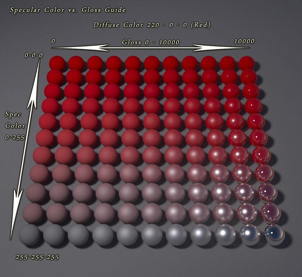
hello, is there a template for a material shader that includes Diffuse map / specular / glossiness and normal map?
I tried using this but the mesh material does not display correctly at all https://answers.unity.com/questions/747568/custom-shader-using-normal-diffuse-gloss-and-specu.html
Unity is the ultimate game development platform. Use Unity to build high-quality 3D and 2D games, deploy them across mobile, desktop, VR/AR, consoles or the Web, and connect with loyal and enthusiastic players and customers.
The standard shader perhaps..?🤔
standard shader does not have glossiness tho
Glossiness is the other name for specular, is it not?
Or rather a different workflow to specular but fulfilling the same function.
I need this to preview my meshes before I import them in bundles
escape from tarkov uses this maps for their meshes
they have a glossiness map a diffuse map and a normal map
and the difusse map has glossiness in its alpha channel
Here. A quick Google proves my pont.
https://forum.unity.com/threads/how-do-i-use-a-gloss-map.297752/
Unity Forum
Ive created a material with the main texture, specularity and a normal map but i cant seem to figure out how to add a gloss map. The only option i see...
Glossiness is just the alpha channel of specular. It defines surfaces that reflect light.
they output different results tho
okay so I use diffuse and specular and normal map in unity
it looks nothing like in the game
Then you're using them wrong.
Gloss map is probably just 0-1 in all the channels. In unity it needs to be packed into the specular map alpha channel(every other channel in it needs to be 0 I think).
so I still have to use glossiness map?
In the game they use diffuse map and in the diffuse map the alpha channel is the specular
and normal and glossiness are its own textures
Then they you'll have to rearrange the channels.
Alpha in diffuse is usually used for transparency in unity.
And specular is responsible for reflective surfaces.
Point is: you need to understand what they use how in their shaders. then you'll be able to map it to the standard shader or your own custom shader.
This screenshot looks like spec color is actually what metallic does in unity. And gloss is what specular does.
Thing is
I need this shader to preview my mesh before importing
So using a certain workflow with alpha channels for unity
Then making another set of textures that use different alpha channels
Then write your own.
Would defeat the purpose
So Its possible to make a shader that take those maps separately?
As their own textures
Not as alphas
So a shader that would take specular diffuse glossiness and normal all separately in a different map
Because that's how substance painter outputs them
Sure. Just write it.
So I guess the standard shaders already split the textures
But from alphas
So I should configure it that it would take separate images as the glossiness
What's wrong with my code(see 2nd picture)? I have a square and I want the all the vertex inside the sphere(less than radius) extrude out(see 1st picture).But effect looks wierd(see 3rd picture).The _Offset is obj's pivot(2nd picture)


You're extruding along the x axis(the red arrow)🤔
Yup.The problem is it extruded not look like spherical rather than it should be
I actually wanna make a trampoline with hollow and raised.I was trying to test it in x axis

Do you have enough vertices there?@clever saddle
It doesn't seem like you have any vertices in the center, so only vertices at the top are affected.
Yes,I have.I think maybe I mix up the v.vertex.Does v.vertex represen object position which center is object's pivot?

Depends on the shader. Based on the name it should be vertex position in local space.
What's your offset is equal to?
1 on w axis?🤨
You don't. At least not without special software. But you're setting that property from C#/inspector, right?
Usually by hooking the output to emission or unlit base color, if the output is in 0-1 range
There are some options like this
https://assetstore.unity.com/packages/tools/utilities/shadergraph-extensions-debug-value-176735
but they seem to be of limited use because usually the results are different per vertex or per fragment
You learn how to use RenderDoc
For points w should be 1?

Thx!Got it
Thx!Got it
I don't know where you check it, but if it's still in object space, pretty sure it should be 0.
Ohhh.Let me have a try
That's why you should probably share more code for us to understand the context.
That being said, I'm not sure if that's the issue, since even if it's 0, it would be 0 for all the vertices.🤔
Assuming the "offset" value is really 0 0 0, I'd assume that the center(pivot point) of your mesh is at the top.🤔
Judging by the screenshot.
a powerful website for storing and sharing text and code snippets. completely free and open source.
The mesh in this screenshot
#archived-shaders message
And the wireframe one look like a totally different mesh though...
#archived-shaders message
Are you sure you're not trying to fool us or something?😬
Wait
I dont
Im a beginner.I know my code is confusing...
I made a mistake.Uncommented a unnecessary line
Honestly, all this math looks questionable to me...🤔
float total_Dist = distance(worldSpacePosition, GLOBAL_ObjWorldPos); //Dist only used for specify which shader is currently working
            if (total_Dist < 3 && GLOBAL_Attachment == 1) {
                float4 new_Dir = float4(1, 1, 1, 1) - abs(GLOBAL_Direction);
                float4 difference = worldSpacePosition - GLOBAL_ObjWorldPos;
                float4 limitedAxisDifference = mul(new_Dir, difference);
                float vertex_Dist = length(limitedAxisDifference.xyz);

                if (vertex_Dist <= _Radius) {
                    v.vertex += (1 - (vertex_Dist / _Radius)) * -GLOBAL_Direction;
                }
                float vertex_Dist = length(v.vertex);
                vertex_Dist = distance(v.vertex, _Offset);
                if (vertex_Dist <= _Radius) {
                    v.vertex += -GLOBAL_Direction * (1 - saturate(vertex_Dist / _Radius)) * GLOBAL_ObjDistance;
                }
            }
            v.vertex.x += (1 - saturate(distance(v.vertex, _Offset) / _Radius));

If w is 1,It's the 1st picture
If w set to 0,and I increase the radius value.It's like this

It does look like your pivot is at the top of the mesh, so all your math is calculated around it.😅
Okay.
Open your mesh in blender, recenter the pivot point. And it should work.
Somewhat
Probably
lmfao.Im a beginner
Okay
If you're doing distance calculations you'd usually truncate down to 2D/3D rather than handling them on 4 components. Can use .xy or .xyz on the parameters to do that.
Okay.I see
When extracting materials from an FBX why does it default to 0.5 smoothness? It's so tedious going through them all and setting the smoothness to zero every time. It's so unnecessary.
@regal stag currently I see these variables defined in Splatmap.shader on lines like this
Properties
    {
[HideInInspector] [TerrainToMeshLayerCounter] _T2M_Layer_Count ("Layer Count", float) = 0

[Space]
[HideInInspector] _T2M_Layer_0_ColorTint ("Color Tint", Color) = (1, 1, 1, 1)
[HideInInspector] _T2M_Layer_0_NormalScale("Strength", float) = 1
[HideInInspector] _T2M_Layer_0_uvScaleOffset("UV Scale", Vector) = (1, 1, 0, 0)
[HideInInspector] _T2M_Layer_0_MapsUsage("Maps Usage", Vector) = (0, 0, 0, 0)
[HideInInspector] _T2M_Layer_0_MetallicOcclusionSmoothness("Metallic (R), Occlusion (G), Smoothness(A)", Vector) = (0, 1, 0, 0)
[HideInInspector] _T2M_Layer_0_SmoothnessFromDiffuseAlpha("", float) = 0
[HideInInspector] _T2M_Layer_0_MaskMapRemapMin("Maskmap Remap Min", Vector) = (0, 0, 0, 0)
[HideInInspector] _T2M_Layer_0_MaskMapRemapMax("Maskmap Remap Max", Vector) = (1, 1, 1, 1)
Do i need to remove them from this Properties{} section and move them into the CGBUFFER part? or leave the Properties{} and just add them to CBUFFER ?
They need to be in both the ShaderLab Properties section and the CBUFFER in the HLSL portion
But I imagine the shader is also declaring them already somewhere in the HLSL portion / include files which you'd need to remove or there will be redefintion errors
Between the HLSLPROGRAM and ENDHLSL tags
got it thanks
he seems to declare int _T2M_Layer_Count whereas your example shows float, is that intentional? is float "better" for whatever reason?
There's probably gonna be no difference. I think many GPUs don't work with int, so they simulate them with floats. Or so I heard.
i thought it was something like that... so int might end up being float anyway sorta thing
From my understanding yes
If they define it as int, probably safer to keep it at that. I couldn't see where they are defined so just made it up based on the property types.
i'm gonna try posting the whole thing on github so the full picture can be clearer
Unless the asset you are editing is free, I wouldn't share it's code
ah
well just the shader codes?...
temporarily... just to troubleshoot & help fix up this requirement... then delete the repo when we're done...
@regal stag these 2DArrays i can leave same as all the 2Ds?
//Texture 2D Array
[HideInInspector] [NoScaleOffset] _T2M_SplatMaps2DArray("SplatMaps 2D Array", 2DArray) = "black" {}
[HideInInspector] [NoScaleOffset] _T2M_DiffuseMaps2DArray("DiffuseMaps 2D Array", 2DArray) = "white" {}
[HideInInspector] [NoScaleOffset] _T2M_NormalMaps2DArray("NormalMaps 2D Array", 2DArray) = "bump" {}
[HideInInspector] [NoScaleOffset] _T2M_MaskMaps2DArray("MaskMaps 2D Array", 2DArray) = "white" {} ```Yeah shouldn't need those in the cbuffer afaik
ok

ok so this is correct, but i cannot figure out why the outline is so oversized when its the same material settings on both. something when it comes from blender is causing the outline scaling to oversize when going from unity > Blender > back to unity
most probably you're not using the standard 1 scaling for all objects... the 1 there is just an example, it can be any number that you'd consider as standard or default value in your project
like, each one of them has a different scaling when importing
also make sure to apply the transform when exporting from the 3d software you're using, for example Blender hit ctr+a then select all transform everytime you change the transform value there
the when exporting, toggle on the Apply transform in Blender export settings
ok i'll take a look at that, thanks you for your help!
This worked! thank you again!
goodluck
@regal stag initial success 🤩 testing now, let's see if this works...

aaand yes it works 🙌
please share link where I can send you some beer 😄🙏
hm now after attempting a build i see an error...

maybe i didnt do this part right...
how do i properly remove these definitions from a .cginc so that i can define them in CGBUFFER ?
#if defined(_T2M_TEXTURE_SAMPLE_TYPE_ARRAY)

    #define T2M_DECLARE_LAYER(l)                float4 _T2M_Layer_##l##_MapsUsage; float4 _T2M_Layer_##l##_uvScaleOffset;   float4 _T2M_Layer_##l##_ColorTint; float4 _T2M_Layer_##l##_MetallicOcclusionSmoothness; int _T2M_Layer_##l##_SmoothnessFromDiffuseAlpha;
    #define T2M_DECALRE_NORMAL(l)               float _T2M_Layer_##l##_NormalScale;
    #define T2M_DECALRE_MASK(l)                 float4 _T2M_Layer_##l##_MaskMapRemapMin; float4 _T2M_Layer_##l##_MaskMapRemapMax;

#else

    #define T2M_DECLARE_LAYER(l)                TEXTURE2D(_T2M_Layer_##l##_Diffuse);   float4 _T2M_Layer_##l##_uvScaleOffset;   float4 _T2M_Layer_##l##_ColorTint; float4 _T2M_Layer_##l##_MetallicOcclusionSmoothness; int _T2M_Layer_##l##_SmoothnessFromDiffuseAlpha;
    #define T2M_DECALRE_NORMAL(l)               TEXTURE2D(_T2M_Layer_##l##_NormalMap); float _T2M_Layer_##l##_NormalScale;
    #define T2M_DECALRE_MASK(l)                 TEXTURE2D(_T2M_Layer_##l##_Mask);      float4 _T2M_Layer_##l##_MaskMapRemapMin; float4 _T2M_Layer_##l##_MaskMapRemapMax;

#endif
do i move this entire block as-is into the CGBUFFER ?
posible to get the root bone transform?
In a shader?
@regal stag in Variables.cginc there are calls to this "T2M_DECLARE_LAYER(x)" passing in a number i think 0 to 15, how can i get Variables.cginc to use a #define from the CGBUFFER ?

yes, is it possible or no?
Not generally within the shader
Amplify can access object scale, and Shader Graph can access object scale and position, but I don't know if those have equivalents in manually written shaders
You can use scripts to get any transform values and pass them to the shader using properties though
Hello folks. I am kinda new to shader coding. I figured that with urp we port cg to hlsl. Most of the materials i find online and also a lesson that i took utilise cg. Should i stick to cg or learn hlsl although i can't find the proper functions of it. If so, how can i find documents about hlsl functions or variables ? Thanks in advance.
You do realize you just attempted to @ 90k people? (It's been disabled)
Ah sorry
Hi everyone ! I'm new to shader and I need to modify a shader to single pass instanced. I can't figure out witch part is broken in my code. I should have these bloody stains:

But I only have this red weird looking :

This is the old code and the new code with my changes :
Why does rendering a terrain with an Unlit shader make it not render at all?
hey so im doing this to read from a raw index buffer in a compute shader, but this only works if the index buffer is 32 bit
How do I make it work with 16 bit?
uint3 vidx = uint3(bufIndexes.Load(idx * 12), bufIndexes.Load(idx * 12 + 8), bufIndexes.Load(idx * 12 + 4)) * 10;

having a problem with this - Length stays anchored at the correct position, but add/add as I rotate the mesh, the effect gets brighter/darker
I think its because when its rotated the positions are sometimes +/+ or +/- or -/-
but I have no idea how to fix that
what I want from it is the effect to not be circular
hrm now its behaving completely differently and I dont know why
im back at a place where I have no idea how to do anything and no idea why anything is behaving the way it does and all I can do is delete all of it and start over, im too lost to solve this
huge fucking mess that does nothing of what I wnat it to do and I have noi dea what im doing because im fuckiung stupid

I want square, I have circle
its incredibly painful and difficult to obtain square
I cant even remember what I was trying to solve with this stupid piece of shit to begin with
what could i do to create a system where i can merge together several layers of textures into one texture?
Did the compute shader not work?
oh it worked well
just thinking of other sections I need to work on now
and also thinking of how to detect when the compute shader is complete
I know compute shaders arent really set up for that, but it would be good to be able to get something to happen once the rendertexture has been updated
Hmm... Do you really need that though?
Maybe you could fill some dummy buffer and get the data on the CPU after dispatching the shader.🤔
I guess i could work around that
I could use the render texture as is for the normal map
I still need to though create a compute shader for combining multiple textures into one texture
I should explain that im making something where i can add a lot of normal map details to an object.
the part i started yesterday was overlaying a detail normal map over a base normal map
but today i need to get multiple base maps put together to make one base map
Well, just average them all up in the compute shader.
ive wondered, what is the difference between a shader graph shader and those .shader files, is one faster than the other, can one do more things, or are they just different ways of doing the same thing?
They are different ways of doing the same thing. Shader graph shader is just an asset that you can edit in the shader graph. When it's compiled it turns into a normal .shader. There might be some differences in optimization due to the shader graph one being generated automatically from nodes, but then again, you could write a terrible shader manually as well.😅
ok fascinating! Thanks a ton!
How can I remove the line running through the center of my cross product?

I would like it to be softer 🤔
im trying to get a mask that runs different from the direction of the light

specially like all of this is XY


I want to emphasize the face from this angle and this angle alone

its fine from other angles but it vanishes from directly on the side
I cant figure out how to emphasize it from the side, I though getting some kind of mask that runs like 90 degrees different from the light direction would work?? but I dont know how to get that
I tried to use just SOME of the cross product channels, but since the light and the object can rotate, I can't reliably select just the ones I want, from certain rotations that changes

same cross product, completely different chanels because the cube itself is rotated

this has what I need, but only when rotated a certain way, how do I only get this no matter what rotation it has?
Okay, ill try that out now.
I am wondering though, is there a way to apply scaling and rotation to textures before passing them to the computer shader to be merged together?
I don't think so. You could do it inside the merging compute shader or a different compute shader.🤔
You'll need to somehow transform the indices of the texture for that. Using a matrix is probably the best bet, but I know nothing about transforming positions with matrices, so you're on your own there.
okay, ill keep looking into things for it
Thank you for all the help!
I can probably figure out the matrix transform with enough time
none of this is working, I can't solve this without help

how do I emphasize the backfaces that are barely visible? I cant figure out how to make some kind of mask that ONLY highlights just that portion

I need a dot product that is 90 degrees rotated from this

but that also works no matter what rotation the light or object are

no matter what I pipe into rotate, it never rotates
not to the way I want, not to anything

I wish I wasnt so stupid that i can't solve a single thing without help :/
im just going to keep posting my failures until I manage to solve it since I can do literally nothing else

this works in this ONE single rotation
but I can't figure out how to make it account for the rotation of the object and the light
its only working because they happen to align in this exact moment
but in practice I dont have that kind of control
do I need to get the rotation of the object somehow???
I guess the third vector is the camera view direction?
some combination of the light direction, the view direction, and the box direction will give me a 90 degree rotation of the light's direction?????
this didnt work

how do i have a default colour input for things to interact with, like how base map automatically takes the colour from the particle system?
Either a color property in the shader or vertex colors.🤷♂️
i have a color property in the shader
Then use that as the base before calculating the output.
how do i set it to be the base?
through blindly plugging things together I think i might have actually got what I wanted 🤔 sorta, its kinda messy still

Depends on your setup. In the simplest form, just plug it into the color output.🤷♂️
already am
Then you're not setting it I guess.
yes i know
i dont know how to set it, cause usually with default shaders they set themselves, how can i set my shader to act like that
Wdym by "set themselves"?😅
How do I get rid of this roundness? it doesnt exist in the UVs


if you plug them into the particle system then it sends the particles colour to the shader as the base map, but this behaviour only appears to happen on default shaders
Ah, you mean properties defined on the renderer. They're probably set to the material somewhere in the renderer code. If you want the particle system to update a property in your custom shader, you'll need to use the same name as the standard shader uses for that property.
ok ill try that, thanks!
Or you can update it manually from your own code with
https://docs.unity3d.com/ScriptReference/Material.SetColor.html

ok thanks
ok giving the same name didnt work, guess whatever magic the default shaders use is not possible on regular shaders, guess ill have to try set the materials manully using dots in some way to save performance
myabe I can somehow get my emphasis lines derived from the original UVs somehow???
moving away from getting itworking again

I'm guessing ive been shadow banned or something since it seems like not a single person has seen a single one of my posts?
Should be possible. What property are you trying to set?
i just want per particle colours, i dont care what property i have to set, ill do anything
If it's per particle it could be a vertex color.
how do i get vertex colours?
Is it a shader graph?
yes
Then I think there's a vertex color node
thanks so much!
We don't shadowban, so no. It doesn't help that your usual posts are a flood of rants and thought dumps though. Nobody has time to scroll back and read everything going on in your mind.
I've seen your posts, it's just that it requires a lot of time and effort to try and figure out what you're doing and what might be the issue. People tend to avoid answering questions they think that they can't answer.
Besides, you've been posting some complicated stuff for quite a while, so I unconsciously feel like this issue is out of my league.😅
hey, so i already create shader which make obj disappear on certain direction, and i want to assign it to my textmeshPro,but there's problem, the text now is broken, did anyone know how to fix it? thanks

Don't change the text material. It should be using Text Mesh Pro materials, or else it will not function.
Just change the Debug Settings of the actual text material. The Cull Mode can be set to Back
this one right?

yes
yes, that's what i did, but it's still broken

?? that's the exact opposite of what I said to do
Don't change it's shader. Don't change the material to anything else. Just change the Debug Settings on the original material.
ahhh, ok thanks for the info
Anyone know if there's a way to organise shadergraphs in their own category, outside of the general 'shadergraphs' category in the drop down list ?
Is there any documentation on the SpriteMask node? Or, alternatively, anyone able to explain how to use it?
The grey path text under the graph title in the blackboard is actually editable if you double click it
Amazing!!
what are you doing the cross product between?
It looks like at some point, one of the components of the product becomes zero and since you're doing an absolute, that leads to a discontinuity in the derivative of that component. Maybe try putting the abs() value to some power to smooth it out, or do something like (v^p + d^p)^(1/p) where v is the output of the absolute node, p is some power, and d is the width over which it's damped
Workflow question. I can create render textures for use in a compute shader through code but I'd like to use a serialized one so I can have it referenced in the scene by a UI component. Only the serialized texture isn't randomwrite enabled (I get Attempting to bind texture as UAV but the texture wasn't created with the UAV usage flag set!) and I can't change it without making a new one. Is there a trick to get both the serialization and a correctly setup texture. Or is there a "non-random write" way I can write to this texture that would comply with whatever settings the serialized textures are created with (I assume these texture can be written to by the renderer somehow)?
You'll need to copy the render texture to a texture 2d if you want to serialize it. Render texture is not stored on the CPU side.
Aah I wondered why it was so convoluted to initialize. Thank you very much 🙂
Here's a water shader I made a while back. It's a mess, but still pretty amazing.
https://github.com/Tespinen/Unity-URP-Water-Shader-Graph

GitHub
A flexible and easily editable water shader for Unity. Made in Shader Graph. - GitHub - Tespinen/Unity-URP-Water-Shader-Graph: A flexible and easily editable water shader for Unity. Made in Shader ...
Panzer, would it be non-trivial to reflect the interior cubic UVs so that you essential see part of a 3x3x3 cube array?


I havent been able to mock up a descent example of what im trying to mean
This is what I mean

but the above was made by brute force copy pasting and offseting the same set of UVs, and only works for those 3 faces, I'd have to copy it 6x times to cover all rotations


correct me if I am wrong but if you are using shadergraph, you ARE using URP
What is the 'this' that is happening?
no, i'm not
it's shadergraph but not URP
the black sides
appears trough other faces too
does anyone know how I could approach having backfaces culled, while still obscuring the geometry behind them?
https://cdn.discordapp.com/attachments/996979168304697384/1022609567756062730/interior_cubes.gif
Better proof of concept but it involved a loooot of copy pasting and doesnt work with refraction, not really feasable for much

have them write to the depth buffer only
(note i have no idea how to actually do that)
It looks like the shader is transparent and isn't depth sorting properly for that reason
Probably the easiest way would be to calculate the cube normal (so if the position is (x,y,z), get the component with the largest absolute value, and for the cube normal set that component to sign(component), and set all the others to zero), subtract the cube normal times either one or two (depending on how everything else is doing the geometry, whether it's assuming a 1x1x1 or 2x2x2 cube) and then redo the calculation to find the next face along the ray
Why are you using a transparent material?
Hm good point sine lets you repeat stuff
Sign, not sine
Sign(x) is -1 for x<0, 0 for x=0, and 1 for x>0
The repeat comes in by subtracting the cube normal, which basically brings you back from the bottom of the cube to the top, so you can go through it again
very cool
i was just going to ask about how to make a water shader
but i think i want something slightly less intensive / slightly less realistic / as optimized & "barebones" as possible
basically trying to mimic this good ol' classic
while i'm hoping to achieve as close as possible effect, i am trying to target mobile so ideally keeping things as dumbed down and performant as possible
unfortunately i don't know the faintest thing about shaders... maybe i'll try working on this in phases, first maybe trying to figure out how to do the nice reflections, then maybe how to do the rather mild water movements, then maybe the shoreline waves effect
any ideas / guidance how to get started would be greatly appreciated 🙏
https://github.com/Unity-Technologies/BoatAttack maybe try looking at the water shader from here?
GitHub
Demo Project using the Universal RP from Unity3D. Contribute to Unity-Technologies/BoatAttack development by creating an account on GitHub.
btw one very important thing I've found, if you have water that uses the background color to some extent, don't just lerp between background color and some water color with the depth (or exp(-depth) if you're being fancy); if you do that, it looks like paint. You have to multiply the background color by exp(-absorption color * water depth) (or similar). One mimics scattering off colored particles (paint), the other mimics absorption (as in real water).
i was actually looking at that, also the video tutorial about it https://www.youtube.com/watch?v=gRq-IdShxpU

In this video, we'll take a look at how we can use the Shader Graph feature in Universal Render Pipeline, or URP for short, with Unity to create a water shader! The water shader can be simple or complex, and include the features you desire. Let your imagination get wild in this tutorial, or simply follow step-by-step to get about the same result...
but it still seemed kinda.... advanced-ish? i didnt know if i would reach the desired effect as in this clip 👆 by starting from this tutorial and then trying to subtracting/remove effects & parts that i dont want or need, OR if maybe it would be more direct to build bottom up, effect by effect, until i have just what i need
2 example concerns;
- does the tutorial have reflection of landmasses as in my clip above? i dont know if it does..
- does the tutorial have fancy/realistic water waves? i think i need much simpler ones to achieve the effect as in my clip above
I would suggest 1) calculating the depth through the water, 2) multiply the scene color by some base value (corresponding to the light reflecting around inside the water plus the sun intensity), multiplied by exp(-absorption * depth through water), 3) sample some normal maps to create waves and move them around over time, 4) use a reflection probe to get reflections off the surroundings, 5) make a mesh with the shorelines painted with UVs (in the vertex colors perhaps) so you can easily paint some waves on top.
ok i am copy-pasting these instructions into a notepad for further studying and learning
also your previous message
now my mission is to start having the faintest clue about what is being explained 😄
btw the absorption color would be reddish orange, rather than blue, because you want red to drop off quickly with depth, and blue to remain.
(just taking some very wild guesses here, really have no clue what i'm talking about...)
is #2 absolutely necessary? maybe just working with blue is good enough? does it look like the clip i posted must be using "scene color corresponding to light reflecting around the water plus sun intensity" ? or maybe they just used some static value without calculating it from the scene
It helps add a bit of extra contrast between shore and water. It's just multiplying by some value so it's not very expensive
(just a light bluish, probably HDR with intensity a little bit >1)
either way my main concern about that is performance/overhead. if these calculations are unbelievably trivial even for mobile then i guess i dont mind doing those additional calculations. but if it has even a little bit of significant/noticeable performance boost, i need less realism and more performance
ah its not very expensive ok
@karmic hatch you seem to know about all this, i'm getting the impression that with your help i might even be able to achieve this. any chance you up for some consultation / DM? sometimes it's a bit frustrating to work on something a bit but then the expert is no longer available in chat for unknown time / time zone / weekend etc..
for pay of course
I'm not much of an expert, I just like messing around. Feel free to DM me whenever
🙏 very kind of you, thanks!
In the boatattack one it looks to me like they sample from a texture to do the absorption and scattering rather than calculating it
which makes sense
aha
as always perfromance-concerned me wants to know; is any one of those less intensive than the other?
Tbh I'm not sure
Found this slide mentioned in a unity forum post

(presentation is titled 'Bringing AAA graphics to mobile platforms')
On mobile, texture sample probably takes as much as "several to several dozen simple math operations".
On PC, the ratio is higher, for one texture sample you can afford dozens to hundreds of math operations.
another guy under the same forum post
someone on another forum claimed exp2() costs around 4-8 addition/multiplication operations (exp would cost one more and any difference could be absorbed into the absorb color)
not sure what these amounts "4-8 addition/multiplication operations" mean, on one hand they sound incredibly trivial, whats a few multiplication ops to a processor/GPU? but on the other hand if that happens each frame each vertex or something... i guess now it could get exponentially expensive
it takes 4-8 times as long to compute
it seems you mainly just want to keep it relatively compact, and avoid stuff like loops
unless loops are absolutely essential to achieve such an effect 👆i'd at least try it and profile a bit, then if it's a no go i'd reduce/remove some computations maybe
true, though I don't think they would be
https://streamable.com/y66ov2
could anyone potentially point me in the right direction as to what is going on here?

I was trying to implement a fresnel effect in a geometry shader, and it works as expected. EXCEPT for when the object is rotated
I have a feeling that this is something super simple that im just glossing over but i've been staring at this for about an hour and nothing is clicking
Make sure all the normals are in world space, not object space
is there a way to multiply a normal map by a quaternion to apply a rotation to the normal map?
cause a normal map is just an image of tangents isnt it?
so a quaterntion multiplication should be able to rotate those tangents around to their correct position
yeah that was dumb of me 😅
something new and interesting has come up though:
it appears to make my object just ever so slightly oblong

I think i know how to fix this though
but, thanks for the help anyways lol
Anyone know of anywhere I can find an outline shader that draws the edges of a cube and not just the silhouette?
Wireframe doesnt work because it draw the tris
i think what youre looking for is an outline shader that works on normals instead of depth
or both, i believe some shaders combine the two but im not sure
Oddly enough I cant find an asset for it either. Seems like a pretty common ask
if you are keen on trying to do it yourself, heres what looks to be a pretty good guide on how to put one together.
https://roystan.net/articles/outline-shader.html
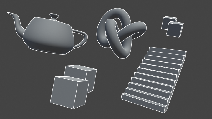
Learn to write an outline edge detection shader for Unity engine, integrated with the post-processing stack. This effect is especially popular as a compliment to toon shading, or in CAD and architectural rendering.
its got a github source repo linked towards the bottom, as well
if I have 1 material/shader, and many objects with same 3D mesh,
but they have independent material data, how to render it with 1 drawcall?
there's only 1 texture, but material params are different. (the roughness, metal)
What do i have wrong with this code here?
`// Each #kernel tells which function to compile; you can have many kernels
#pragma kernel CSMain
#pragma kernal MultiQuat
#pragma kernel RotateVector
// Create a RenderTexture with enableRandomWrite flag and set it
// with cs.SetTexture
RWTexture2D<float4> Result;
// The normal map that will be rotated
Texture2D BaseMap;
// The amount it will be rotated by
float4 Rotation;
[numthreads(8,8,1)]
void CSMain (uint3 id : SV_DispatchThreadID)
{
Result[id.xy] = RotateVector(Rotation, (BaseMap[id.xy] - 0.5) * 2);
}
// Quaternion functions
// Summary:
// This function multiplies a quaternion by another quaternion.
// Parameter q1: Quaternion 1
// Parameter q2: Quaternion 2
float4 MultiQuat(float4 q1, float4 q2){
return float4(
q1.w * q2.x + q1.x * q2.w + q1.z * q2.y - q1.y * q2.z,
q1.w * q2.y + q1.y * q2.w + q1.x * q2.z - q1.z * q2.x,
q1.w * q2.z + q1.z * q2.w + q1.y * q2.x - q1.x * q2.y,
q1.w * q2.w - q1.x * q2.x - q1.y * q2.y - q1.z * q2.z
);
}
// Quaternion functions
// Summary:
// This function multiplies a quaternion by another quaternion.
// Parameter q1: Quaternion 1
// Parameter q2: Quaternion 2
float3 RotateVector(float4 quat, float vec){
float4 qv = multQuat(quat, float4(vec, 0.0));
return MultiQuat(qv, float4(-quat.x, -quat.y, -quat.z, quat.w)).xyz;
}`
cause im trying to run this compute shader to test out the shader, but im getting errors with the kernels

i know the comment for the last function is wrong, i just copied the last functions comment format.
wait i know
sorry
the functions have to be put in order of usage
got it working
!!!
just need to get a render texture to work right with it
the script works well with a new one, but doesnt work well with a pre made one
im doing research for a face customisation system in unity URP, with the option to mix and match eyeshadow, eyebrows, lipstick, face paint. What is the best way to go about allowing a player to mix and match all these? is it better to use a single shader with lerps for the head, or just have planes floating on the face and use different materials with alpha blend for each face part?
what does this mean?
Compute shader (NormalRotationShader): Property (Result) at kernel index (0): Attempting to bind texture as UAV but the texture wasn't created with the UAV usage flag set!
u are trying to write into texture that does not have randomWrite enabled, if u are passing RenderTexture, after u created it do _renderTex.enableRandomWrite to True before passing it to ComputeShader. If you are trying to pass Texture2D its a bit more complicated
trying to pass a render texture
but I cant set the read write on it
I cant see where to do that in editor
and I cant do it in code
Hello! Is it possible to create a shader in built-in renderer that displays something that is not there, for example a forrest outside the windows
the closest thing i could find is the spider-mans fake interior shader, but it displays a limited space
hmm u create renderTexture in editor i see, so it should not be problem there, did u enabled Read/Write on normal map texture? BaseMap
you can try parallax effect, basically offfset uv base on viewDirection to make it look like its in the distance
true but im afraid that would'nt look good in my case, i need something similar to stencil but for it to show specific thing behind it, instead of inside it
Could cubemap (similiar to reflection probe) work?
ill try to draw it to explain better 😅
the game is semi top down, perspective camera

it needs to sort of fake extension of the current um.. biome?, once the player passes this wall, they see that it was fake
You could probably use a modified wireframe (drop the check for one side of the triangle)
one way i see how i can achieve this is by masking what to show through this wall, but im not sure how to instruct the camera to render specific objects through this shader
if there is a more performance friendly approach, i would love to hear it
https://www.youtube.com/c/t3ssel8r, https://assetstore.unity.com/packages/vfx/shaders/fullscreen-camera-effects/propixelizer-177877 Would this kinda style work with a perspective camera instead of an isometric one? My main concern is pixel creep, the object changing when you move around it, etc. Is there a workaround to make it work?


Add depth to your project with ProPixelizer asset from ElliotB256. Find this & more VFX options on the Unity Asset Store.
because my atlas contains transparent textures