#archived-shaders
1 messages · Page 3 of 1
Transform sun direction to object space, then use rotational symmetry to your advantage (you only need an angle between the Sun and your point on the sphere)
So just acos(dot(object space sun direction, object space position))
For the angle
Though I've heard acos is slow in shaders and to avoid it where possible
But the cosine of the angle is very useful anyway
Thanks again Pink, Ill try that out when I get back on the horse 👍
Returns a refraction vector using an entering ray, a surface normal, and a refraction index.
Is that what I am doing here? I am familiar with refract custom nodes and refraction but it did not occur to me that this is what im doing here
Reflection is like what a mirror does, refraction is what happens when light goes through a substance and changes its direction a bit due to the different densities (refraction index). Think how a stick looks bent if you put it in the water.
So you used a semi-transparent sphere as an example. Crystal ball, whatever. So there's refraction going on, and some reflection too.
You may also wish to use a cube map, and check out the cube map routines for dealing with surrounding reflections/refractions.
Hey so Im trying to make a shader now to just slap on a material to modify the contrast of a tilemap... but what do I use the tilemap as the input in the shader???
if I just connect a contrast node to the master color it blackboxes all my tiles
cause I have to modify the contrast inside of the shader, but within the shader, how do I specify the tilemap as the target???
had to use the tilemaps base texture as the input
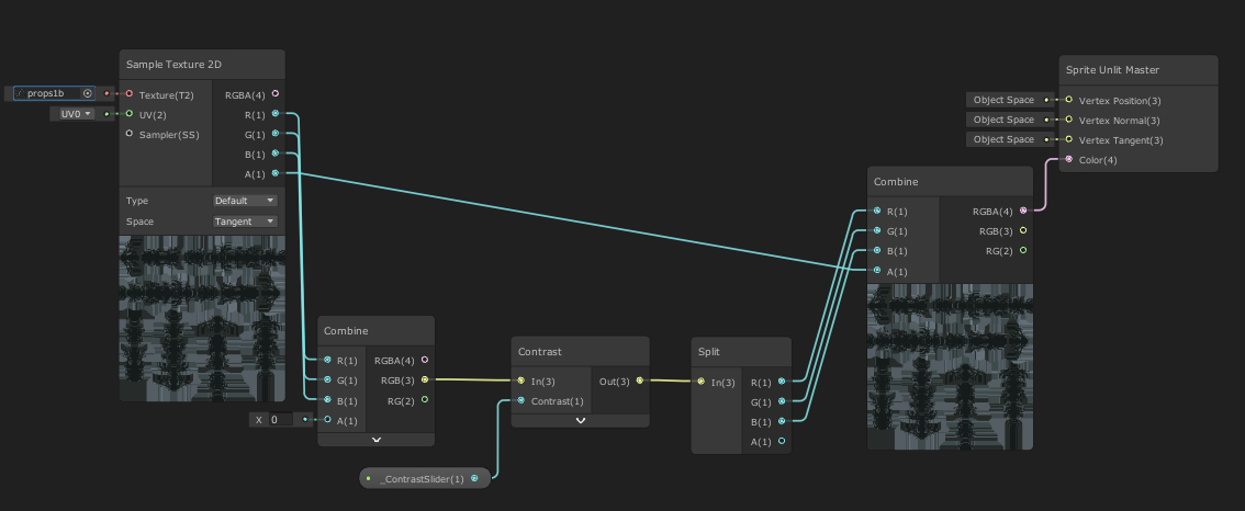
hmm so I'm trying to add saturation to this, but I'm not sure how to incorporate it all back together

add and multiply both result in some unwanted effects
can you not just put the contrast and saturation nodes successively, so either contrast > saturation or the other way around?
Is it possible to do multiple passes with shader graph in urp?
yea, this was actually the solution the came to too
saturation first then contrast, instead of doing them in series
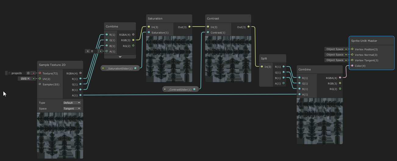
I could even implement hue, but I'll save that for another time
Saturation and constrast is all I care about in this case
For some reason, i cannot set global/local keywords/properties in shaders on any before event, such as RenderPipelineManager.beginCameraRendering, Camera.onPreRender, MonoBehaviour.OnPreRender
I am trying to make a material set a keyword flag for when a particular camera is rendering it, so it has a different look without need to duplicate geometry.
See this example code: https://gist.github.com/Lachee/6141391a039d3f0ab565d14786021f1a
do i need to listen to a special event or something before i can change the material properties? How will i go about making a material have different properties for one camera vs every other camera
Set the value for the material in script.
The RenderPipelineManger.beginCameraRendering event is for c# scripts. So use a script.
Set the property on the material to true if it is your special camera, and false otherwise. Done.
You'll probably want to use renderer.sharedMaterial if you have that same material on several objects, rather than having to make material instance for each object, but that's up to you.
And IDK why your shader global isn't working.
Just tested (with edited script, but basically the same), in URP 2021 lts. Seems to work.
private Camera enableForCamera;

void Start() {
    enableForCamera = GetComponent<Camera>();
    RenderPipelineManager.beginCameraRendering += OnBeginCameraRenderering;
}

void OnDestroy() {
    RenderPipelineManager.beginCameraRendering -= OnBeginCameraRenderering;
}

private void OnBeginCameraRenderering(ScriptableRenderContext context, Camera camera) {
    if (camera == enableForCamera){
        Shader.SetGlobalFloat("_TestFloat", 1);
        Shader.EnableKeyword("_TESTKEYWORD");
    }else{
        Shader.SetGlobalFloat("_TestFloat", 0);
        Shader.DisableKeyword("_TESTKEYWORD");
    }
}
If yours isn't working, add a Debug.Log, make sure the code is running somewhere. Also make sure the keywords/properties are global.
- In Shader Graph that's in the Node Settings tab of Graph Inspector, "Global" on the keyword scope and untick "Exposed" for properties
- In code, make sure you are using
multi_compile(notmulti_compile_local) and don't put properties in the ShaderLab section at the top, only define them in the HLSL
No, shader graph doesn't do multi-pass. URP also uses single-pass forward rendering so you can't really use multi-pass in code-written shaders either. You can technically use two passes with different LightMode tags ("UniversalForward" and "SRPDefaultUnlit"), but it would break the compatibility with the SRP Batcher. It's better to use separate materials instead.
Can assign multiple materials per renderer, or if you have lots of objects can put them on a Layer and use the RenderObjects feature to re-render that layer with an Override Material.
(Or you can use a custom LightMode tag, and specify that in the RenderObjects feature)
@regal stag do you know if unity terrain editor already has support for shaderGraph or not? I remember they've this planned like two years ago on their git repo
i got it working on a basic scene with just modifying global shader properties. its so bizzar its not working in my other scenes; im redoing the scene and seeing what might be causing it.
i do have like... 4 cameras, 3 10k render textures, and a couple additively loaded scenes so something going funky
You can add texture properties with references : _Control, _Splat0, _Splat1, _Splat2 and _Splat3 (as well as the _MaskX, _NormalX, _MetallicX, _SmoothnessX) for up to 4 blended textures.
Can't do more though, as that requires the Dependency "AddPassShader" iirc, which Shader Graph doesn't support.
ah ok.. we'll try to play around with it then.. thanks! 👍
does changing color of a material in code creates a new instance of such material?
I ask so bcs I want to animate color through DOTween
By accessing shader.material yes
Yes
MaterialPropetyBlocks are one way to do the same thing without creating material instances, though it's not compatible with SRP batching
I could make a shader graph that would change color though. I think it best what I can do
On URP/HDRP I don't think it's bad to create material instances as long as you keep track of them and destroy them along with the object
hehe no I won't keep track of them
I am a simple man
you see I wanted to make my material sort of blink so that is why I asked
changing alpha channel of a color on it would create instances each frame
it is dangerous
so I would make shader instead
It doesn't create an instance every frame, just once for the object so it can be changed separately from the rest
oh yeah?
It becomes a problem if you have a huge number of objects, each with their own instance, or if you're spawning and destroying such objects rapidly and filling memory with loose material instances
hello guys
I'm trying to track down the issue with a grass geometry shader
It generates root points for grass blades in the tessellation stage by subdividing the source mesh
then for each vertex it generates simple grass blades in the geometry stage
everything's fine, except the areas right on top of the edges of the source mesh
I can see that tessellation produces new vertices there just fine, but it looks like they are not passed down to the geometry stage (I'm not sure this is the case), and it causes visible empty areas to appear
maybe someone had experience working on a similar shader and recognizes the issue ?
source mesh

blades with a visible empty area

tessellation that generates the points


i am getting this error while building to android
could not find anything on google
i made 2 shaders and there are literally just 5 objects that have those shaders on, and it took me around 40 mins to build my project.
i turned off mesh optimization, i preloaded the shaders but nothing worked, and after waiting for the build to complete for this long, i got these errors
Built in pipeline
I'm sorry i forgot to add this
Yeah, so shader graph is not very compatible with birp.
might want to switch to urp
Or not use shader graph
Donno, it only mentions SRPs in the docs.
https://docs.unity3d.com/Packages/com.unity.shadergraph@15.0/manual/index.html
Shader Graph support for the Built-In Render Pipeline is for compatibility purposes only. Shader Graph doesn't receive updates for Built-In Render Pipeline support, aside from bug fixes for existing features. It's recommended to use Shader Graph with the Scriptable Render Pipelines.
So yeah, you shouldn't use it for birp in production

Unity
Unity is the ultimate game development platform. Use Unity to build high-quality 3D and 2D games, deploy them across mobile, desktop, VR/AR, consoles or the Web, and connect with loyal and enthusiastic players and customers.
Here, it says shader graph added for built in render pipeline
Where?
Shadergraph: Added: Added a new target for the Built-In Render Pipeline which includes Lit and Unlit sub-targets.
This is what it says
You can search "Built-In" on the page
And you will find it, it's a little deep
Well, it doesn't mean that you should be using it. Or that it is as compatible as in URP/HDRP.
They explicitly say that you should avoid using it on BIRP. And that's in the latest version.
Which is the latest version of shader graph?
you can see in the link that I shared - 15
The built-in target should still work even if a SRP is recommended. If you're encountering errors when building it's probably a bug. Could try upgrading unity version or submitting a bug report.
This is what I was thinking, also it works clearly flawlessly in the editor tho.
But yeah, I guess it would be considered a bug.
There are probably platforms that have issues with it.
I have posted on forum to see if anyone replies, i will try different unity version now to see if it works there or not
This could also be the problem, i Haven't tested any other platform, will also try this.
Btw these are the errors I'm getting, for a reference
hi i am not that familliar with shaders. i have this Height Depended tint shader with following function that is responsible for the color:
void surf (Input IN, inout SurfaceOutput o)
{
  half4 c = tex2D (_MainTex, IN.uv_MainTex);
  float h = (_HeightMax-IN.worldPos.y) / (_HeightMax-_HeightMin);
  fixed4 tintColor = lerp(_ColorMax.rgba, _ColorMin.rgba, h);
  o.Albedo = c.rgb * tintColor.rgb;
  o.Alpha = c.a * tintColor.a;
}
is it possible to make _ColorMin more dominant like in picture

so the color begins to change a bit higher than normal
ohh nvm
you could use any easing function you want
right now you're using a linear interpolation
How do I send a per-object value to a shader?
I'm trying to make a "palette swap shader" so my sprites may use the same artwork, but each can specify a different palette index for the shader to look up on a reference texture.
I have done this in Kha (that's like OpenGL) embedding the index in all 4 verts of the quad, maybe I can do the same thing in Unity
i am trying to create a shader to cull pixels, following this tutorial: https://danielilett.com/2021-03-19-tut5-15-wall-cutout/
i have followed it but my output is a pink rather than the output shown on the tutorial?
i am also using a Lit URP shadergraph


this is the .shader file that was compiled from the shadergraph:
A magenta/pink result means the shader has an error (unlikely with shader graph), or is not compatible with the current render pipeline.
Make sure the target matches your pipeline. (set under Graph Settings tab of Graph Inspector window, toggled with button in top right of graph).
Also make sure URP is configured correctly. See pinned messages in #archived-urp channel
thank you i had not set up URP properly!
I know there is a parallax offset node, but can anyone tell why my graph and the real code are not equivalent? I'm not getting the expected results


Where have I made a mistake?
is it a pedmas/pemdas problem?
The View Direction node should be in Tangent space for parallax
Ahh I'll try that 🤔
Hmm that just made it way worse

I could just use the parallax node but I'm doing this as a learning project to get a better understanding of shader math
You should also be using the result as an offset, not to replace the UV entirely. Can use a Tiling And Offset node for that
Or UV node and Add
is maybe my p- I was about to say that
maybe the math is fine but I am using it wrong - Ill try that
What a coincidence @regal stag
I read all of this https://www.cyanilux.com/tutorials/intro-to-shader-graph/
A detailed introduction on how to use Unity Shader Graph (including v10+ changes). Graph setup, Data types, Understanding Previews, Properties, Keywords, Sub Graphs and more!
Then i suddenly remembered I saw that profile pic somewhere
That + Tangent space fixed it, thanks for pointing out my mistake 👍 Glad to know I didnt goof up the graph too badly, it was just how I was using it
I read all of it and it was really helpful. So for my previous problem, i changed the platform from Android to windows and it did not give me error
I upgraded to 2022.1.11
And when I changed the platform to mobile, it gave me same error while building it.
One thing i could not understand here is, you stated that one should apply a render pipeline asset if the shader graph is installed manually (which we only in built in pipeline) but how does one apply any pipeline asset in built in render pipeline.
That's referring to installing urp/hdrp manually via the package manager, not shader graph. (as just installing the packages isn't enough, they need to be properly configured, like assigning the pipeline asset under the Project Settings)
Sorry that maybe isn't clear.
Wait, so does that not mean it's still urp and not built in render pipeline? I mean if we have to install urp then it's not really built in pipeline anymore? And unity stated it works for built in pipeline as well. This is a little confusing.
Cause by changing the platform i was not getting the error anymore (without installing the urp)
You don't need to install URP to use Shader Graph. It does have Built-in support in 2021.2+.
The article is intended for all pipelines, so I mention URP/HDRP as shader graph is automatically installed alongside them. While for Built-in, you'd need to install the Shader Graph package.
Aah so that's for shader graph? I mean in your article, your saying install shader graph manually from package manager? I got a tiny bit confused when it said I need to apply a render pipeline, which we can only do in urp or hdrp, right?
Yes that is only for URP/HDRP
Aah i get it now, thanks
Mate, just one last thing, if you got like couple of mins?
Only if you don't mind, it would take you like max 2-3 minutes to reproduce this error that i am having. And then maybe you can better understand this? I mean i am coming to built in pipeline from urp because I had to drop urp for lower performance on mobile. Now birp works flawlessly and have great performance but i cant really see any other option if the shader graph doesn't work in built in pipeline. So if you don't mind. It won't take longer than 5 minutes.
If you want to try it
Steps:
Just create a new project with built in render pipeline
Install shader graph from package manager
Create a new shader graph(lit)
Just hook up color property to base color
Create a new material out of the newly created shader graph
assign a color to material it in inspector (maybe red, or anything other than white)
Build the project for Android
That's it.
I haven't got unity properly set up on this pc to test. But if those are the steps you need to take to reproduce it, it's definitely a bug. Should do a bug report, so hopefully it can be fixed.
In the meantime, you may want to avoid using shader graph for Android, or switch to URP (if possible)
its exactly that easy, like this is what you get when you do the steps above

do you by any chance have any idea what it could be tho? i am sorry if i am asking alot, but you know its a little disappointing to see it not work.
also where do i make a bug report tho? never made any so i have no idea
It's trying to find a macro/keyword or something that doesn't exist. But I have no idea what is causing that, I guess the graph is just generating the code wrong or missing an include line.
Should be able to make a report via one of the buttons on the File, Edit bar. Maybe under "Help" iirc?
ahh okay thanks mate! thanks for all the help. i am going to make a bug report now. hopefully it could be fixed
Hey epic devs
I want to know something about draw calls not sure I can ask here but do tell where I can if I shouldn't here
When does every draw call happen?
Every frame? every x seconds within 1 frame?
Every frame. Every object on screen is drawn once every single frame
Damn so if you don't batch things up and have over 60 objects and your device runs on 60fps
Then like that you'll have frame drops right?
What?
What would happen if you have 100 objects to be draw on screen and your pc cannot run over 60fps
What would happen? Would you have frame drops?
All 100 objects are drawn 60 times every second right?
So 60fps
No so I have 60 frames to work with and I need to draw 100 and since every 1 frame can draw 1 object
So it will be able to draw to 60 objects and still have 40 that weren't drawn yet
Anyone know if we can setup instanced properties in shader graph now (without editing the final shader manually), such that we can use DrawMeshInstanced with them by passing in the MaterialPropertyBlock.
In the past I've managed to get instanced properties via a custom function

As AleksiH mentioned above, every frame all objects (at least the ones in the viewing frustum) are drawn, not just one object per frame.
But it's hard to say how long it takes to render a frame, as it'll vary - depending on how many draw calls (objects / batches), what shaders are being used and the target platform/gpu. You'd likely need to try and profile it. Then optimise later if necessary.
The statistics window might help a bit. https://docs.unity3d.com/Manual/RenderingStatistics.html
(Though in URP I don't think it displays the SRP-batches, not sure how helpful it is)
Question, I was learning from a tutorial and I noticed the result looks suspiciously like a fresnel

is that just what fresnel is under the hood?
Yep
Hey, I'm writing a custom shader for TextMeshPro (Specialized anti-aliasing for a pixelated raster font) and I want to use Unity's UI effects components. Does anyone know what I'd have to do to support those in the shader?
Pretty interesting seeing these effects under the hood
Can see the generated code for each node btw on the Shader Graph docs page. Right-click nodes and select "Open Documentation". Though recreating things in the graph may help understand it better if you aren't used to hlsl.
I'm having lighting issues with the unity toon shader (https://docs.unity3d.com/Packages/com.unity.toonshader@0.7/manual/index.html)
It works perfectly fine in the editor, but in game the lights flicker a lot.
Image 1: Standard shader in game
Image 2: Toon shader in editor
Image 3: Toon shader in game


Does anybody know of a fix?
looks like URP 's point light limit
I'm on the standard render pipeline
might still be a pixel light count issue ? 

oh right, doesnt happen with standard shader
yea, it's pretty confusing lol
It is most likely. It's not rp specific, but rendering path thing.
forward rendering has a limit of point/pixel lights. Deferred doesn't, but it's a bit heavier by default.
how to fade an UI component from middle to edge
like the alpha is 1.0 in center, but 0 on outside
there are no exact tutorial about that, all i know is it can only done by making a custom shader
to be simple, alpha gradient
Hey ive been looking at a few videos on game toon shaders and have a little question
Are shaders normally used on the entire games models like the player model and world around the player
Or are they used on only a few models like player models to help performance
is there a way to get 'Normal From Height' less aliased and pixelated?

im using voronoi there, I've seen that normal from texture is better, but I'm not using a texture in this case
Why is shader graph fucking up the colors here?

What is that shader trick where you combine two things and it ends up being a bunch of colored bands

I forget how its done or how to describe it so I cant google it reliably
Im trying to make random rainbow noise
this is what I meant by bands, maybe finding it now

Should be able to use the noise texture sample as the X coordinate for sampling the rainbow tex. Maybe remap the noise a bit first. Then connect to UV port.
For bands, can use Posterize node.
Oh yes that's exactly what I was trying to do 👍

It didnt do what I hoped for but looks good at least

I've been struggling to make "sparkles" similar to this, ive tried a bunch of different sparkle/glittery tutorials but none have looked the way I hoped for
either they left out too much 'assumed' info that I couldn't finish the tutorial without, or the effect simply wasn't what I was going for
a lot of tutorials are like 'just add parallax' and it doesn't do anything remotely like what they have there to attach it to a parallax node

this is allegedly the method to do that above affect
I feel like about 50 more critical things are being left out

mine kinda looks like dogshit :/
doesnt do a single thing I set out to make it do, just shittier copies of other far better effects
Its not actually. Try to split r, g and b to see how it outputs hue, value and saturarion values correctly. Now you are converting the color into hsv and visualize hue, saturation and value as r, g and b component
Oh x) I'm tired. I had another conversion from HSV back to RGB, but it was set to RGB to RGB so it looked wrong at the end. Thanks!
Why does my subgraph create an entirely different effect than what it outputs in my shader?
subgraph:

shader:

even when i remove the inputs, so that it only relies on it's own values, it does it's own thing
Refraction and everything looks pretty good imo, just multiply the color for each sparkle by pow(dot(view direction, sparkle normal)*0.5+0.5, 50) or similar and then they'll sparkle depending on the angle (you can make it dependent on the direction to the light source but it probably won't matter too much since you won't be identifying the individual ones anyway)
I tried to do that but I just fucked everything up and it never looked right

Ill throw all of this out and try again from scratch with that formula
Did they just not change much?
Try increasing the power a lot
either you could see nothing, or see all of them, nothing would do 'some of them'
rebuilding atm
pow(dot(view direction, sparkle normal)*0.5+0.5, 50)
is the order of this
dot of:
view direction and sparkle normal
THEN multiply and add after? or before?
Multiply then add
It's roughly the same as saturate -> pow
Shouldn't be functionally different
What is that 50 at the end?
The power
is the dot product between all that stuff and 50?
oh right the first thing is pow not dot
Dot is between view direction and normalize(sparkle normal)
I didnt see the pow at the start
Just make the power >> 1
If it's close to one, you just have diffusely lit things, not like specular highlights which you want
What space should the dot product be in? Every space I try (object, world, view, tangent) results in no sparkles or all sparkles

or they do really weird stuff like only sparkles on the -x -y faces of the surface
all four of them, its not changing at all when I rotate the mesh
I think view space won't work, but anything else will (you just want the view direction to be able to change). Object space or tangent space would probably be best since they'd make it change as the mesh rotates

Im doing something wrong here but i'm too inexperienced to understand what or fix it
Also you need to make sure the normals for the sparkles are distributed on all sides of the origin, you don't want all of the components to be positive or something (but in tangent space I think the B component should be positive always?)
increasing/decreasing power only makes it look worse, broken texture pink
How would I make sure of that? How would I know if that is the problem
Make sure everything is normalized

If they're initially all 0-1, you can do x -> 2x-1 and then it goes -1 to 1. Or just use the values to lerp between -1 and 1
I'm doing something completely wrong because it just wont sparkle no matter what values I put in

it fades in and out completely as a single unit, and the faces are all @#$%^ up some showing, some not, some in reverse
I've been fighting with this all day long and I just feel fucking stupid and worthless, I can't do a single thing on my own
literally 100% of my "successes" are my successfully getting help from someone else to fix my stupid piece of shit mess :/
im getting really discouraged
I wish I wasn't such a stupid failure
(Sorry for butting in guys)
Nope
The random color texture is sampled.
In the example image, they ONLY subtracted .5 from the color RGB result. They didn't mulitply by .5 (although I'm not following the conversation well, so I hope you'll both excuse me if I F*** this up).
That result is a directional vector where the RGB components range from -0.5 to +0.5
They then applied the dot product of the view direction and that random vector, with a Pow or whatever.
I dont really understand anything of what you just said
are you saying I should multiply before at some stage?

all my efforts are just complete dogshit it wont do a single fucking thing and im beyond emotionally compromised im not able to contine working on this without going into crisis
In that example.
im going to close discord now
OK, chin up!
The multiply should be irrelevant since you normalise
Sure, but IDK that they normalized either. Interestingly. Although I'd guess that you would normalize both vectors.
And then there's the question of how to apply the random color texture to the cube in 3D space. I'm not sure I can tell from that one image how they did that. Maybe they had a texture3D?
bunp is right in that the explanation falls a bit...short...IMO.
I think through UVs? Triplanar mapping would certainly work well
why would my subgraph eb giving me a different outcome from my shader?
@tight phoenix here i just took voronoi noise (i used 3d voronoi but you could try some triplanar thing or some other method to optimise it as 3d voronoi is slow), used the cell values to create 'flakes' with random normals, then used fairly standard specular (pow(dot(reflection(normalize(view direction), normalize(random normal)), sun direction), 200)) to make them sparkly
there are some strange correlations which is probably because of the way the random normals are distributed (not uniformly enough) but whatever
Btw I put the output color into emission
Might want to also multiply by saturate(dot(surface normal, sun direction)) so they don't sparkle in the dark bits unless you want that
Does anybody know a good technique to achieve an inline effect on 2D sprites? I tried using the Step node on ShaderGraph and it worked, but the inline is very thin and I couldn't make it any thicker...
I'm using the shader graph and my material is always purple even tho I am changing tue colour
Probably using an incompatible render pipeline with an incompatible shader graph version.
Idk I'm new to shaders
here's the shader if you wanna take a look

Yeah, you're probably using built-in render pipeline. And the shader graph is only compatible with it from unity version 2021.2 or something.
I'm using the universal render pipeline and the default lit shader
Do you have the urp set up properly?
idk
Then you should probably look it up.
ok thx
quick question , does this mean unity compiles 1000 million shaders or is it 1000 megabyes ?

Anyone have a clue how to implement sprite sorting with a custom mesh + shader graph?
I think it's megabytes. There are many shader variants, but millions is on a totally different level.
Oh, apparently there's a sorting order property even for regular MeshRenderer.
Hey y'all 🙂 Can anybody tell me why this shader is not able to stencil? Is there anything I can do about that inside shader graph?


afaik shader graph doesnt support stencil buffer stuff
so, I made a shader to simulate the refraction of light from water above for a game that is supposed to play out underwater. But when I apply it to an object in unity it only works on one side of an object, anyone know why?

I'm very very new to unity shaders so I have no idea how this works
Is it like that in world space or object space?
what do you mean?
If you rotate the cube is it sticking to the same side or us it always facing the same direction?
facing the same direction
Sounds like you have accidentally mapped the texture in world space in one axis
oh! did not know that. do you know how I can fix that?
this is the last part of my shader

Is this using a texture?
yeah
Then the problem is probably where you sample the texture

i tried changing it to object space as well but it didn't seem to change
should it instead be sample texture 3d?
What is the uv input?
Im kot exactly sure but i think texture 3d is. For itger types of textures not for 3d geometry

There we go, wold position as UV. If you want it ti scroll you should be using the x or y value of the UV not world position
I don't use the shader graph much so i don't know the name of the node you need but it should just be the mesh uv
and changing the type of position? would that help?
Yeah, the UV input of the sample tex is essentially used to map the texture around it. If you aren't using the values that defines where and what should be where, ie, the UV coordinates it will map differently. In this case in world space
is it just a UV node?
If you try to output the world position as the color vs the uv as the color you will se what i mean
Yeah should be
So, I tried a UV node. It worked somewhat, but I did realize that now not all the planes have the same size
as you can see here


Could continue using the world position, but Swizzle it with "xz" so it projects from above. It will still stretch on sides of objects though
^ yes, i didn't realize thats what he wanted
But i assume you also want this texture to not effect the sides and bottom if this is an overlay for another texture
Does anybody know a good technique to achieve an inline effect on 2D sprites? I tried using the Step node on ShaderGraph and it worked, but the inline is very thin and I couldn't make it any thicker...
hey all, does anyone know if there's a way to get all these options from the URP Lit material into a shader graph? if it has to all be done manually, has Unity put out any resources on how to do this?

im still trying and failing to do glitter, im critically missing something, im not understanding something to make it work and I keep grinding my gears against it and failing to get any traction

I have a texture for testing random colors as vector directions to mask which parts of the glitter will be visible or not

but I cant figure out what im actually supposed to DO with it
what space it should be in, should it be added, multiplied, dot producted, literally anything I have no idea
everything I try looks completely wrong like complete shit
I really need help on this I cant do it on my own
and my mental health is in the pits, admitting that openly that im so worthless I cant do something this simple on my own is tipping me over the edge into criss, time for me to close the internet
Trying this now
Optimally you'd distribute them across a sphere surface evenly rather than across a cube but that is slower
Maybe you could create a random matrix and rotate but that's more effort too
I have some voronoi dots but im struggling to reproduce the next bit:
(pow(dot(reflection(normalize(view direction), normalize(random normal)), sun direction), 200))
What is the reflection normal? and what is being dot producted? How do I get a random normal? What space is the view normal in?


oh the reflection is between the view normal and random normal
and the dot is between the that and the sun direction?

im pretty sure im doing the reflection step wrong
and clearly doing the power step wrong

the raw voronoi isnt the answer
i wish i just understood, i wish i just knew the answer, i wish i had the ability to solve anything or even begin to know what step is wrong
is this "flakes with random normals" ???

WHAT AM I DOING WRONG, WHY WONT IT EVER @#$#$^#$^ WORK

i get so fucking furiously angry at how fucking worthless and useless I am and i get so fucking angry at how knowledgeably everyone else is, things for you are so easy that you can literally just immediately type out the answer bracket flow like its nothing, and im too fucking stupid to read between the lines
i am in crisis now leaving again
why. wont. it. just. fucking. work
Why am i so fucking stupid
why cant i do literally anything without my hand being held
why can i be handed the answers on a golden plate but im too fucking stupid to know how to pick up a fucking fork and eat the answers
Use the cells as your flakes, then use the cell values as seeds for new random numbers (can be as simple as multiply by big vector3 and fract)
I've just spent lots of time messing around with this stuff, it just takes time to develop an intuition with how to get to the effect you want
i desperately wish I could not feel emotions, my feelings hold me back from achieving success
if I could just act rationally, think clearly, not get down by repeated failures
Ill try this when I relaunch unity
which wont be today
thank you for your kind words and patience
fair, it is really frustrating when something that as far as you can tell should work, doesn't
I'll drop this here for fun.
This is NOT sparkles.
But it is a nice clear video tutorial, with shader graph, on how to make translucent crystal like things, with screen space refraction. Sparkles could be added to it. And this time I won't butt into the ongoing discussion about those.
https://www.youtube.com/watch?v=tIW2zM6ed8o

Refraction shader using ShaderGraph, works both on URP and HDRP. Uses the opaque texture to achieve screen space refraction.
(づ ̄ ³ ̄)づ ~(˘▾˘~)
TWITCH ( ͡° ͜ʖ ͡°)
https://www.twitch.tv/PabloMakes
TWITTER (ಥ﹏ಥ)
https://twitter.com/PabloMakes
₪ ₪ Time Stamps ₪ ₪
00:00 - Intro
01:57 - Opaque Texture
05:09 - Refraction
13:14 - Normals
...
Hello everyone, I have a procedurally generated map and some textures are applied to the mesh according to the height of the regions. I also got a curved world surface shader I found from the internet (for a planet-like look). I am a complete beginner in shaders but I managed to merge the 2 shader together but it seems like the vertex modification is done first and then the textures are applied, so the far sides of the map is just water. Is there a way to fix this?
You'd need to pass the vertex position before displacement (or just the Y/height I guess) through to the fragment shader. Is this in shader graph?
No it's a surface shader. I see that's the thing I need to do but because I'm a beginner in shaders and because there isn't much about this on the internet I don't know how to do it.
Ah okay. My knowledge on surface shaders is a bit lacking, but I imagine you'd need to add your own variable to the Input struct (e.g. float3 customWorldPos;) rather than using the built-in one.
Then in the vertex modification function (probably named "vert"), should be able to specify out Input o as an additional parameter, and use o.customWorldPos = mul(unity_ObjectToWorld, v.vertex).xyz;, before the v.vertex is modified that is.
Also edit the surf function to use IN.customWorldPos instead of IN.worldPos.
make a variable in your v2f structure, and assign the value you want to stash BEFORE you modify it (or at the right place, maybe after Object2World but before WorldToClipPos, or whatever makes sense. IDK your code.)
Sorry Cyan for butting in, I was just typing this as you replied.
Hey guys, im looking through pins and comments tho im gonna ask.
What are some good and hopefully up to date resources for shading programming with Unity?
Im interested in learning shading coding as well as using tools like shader graph.
Hello, everyone!
Does anybody know a good technique to achieve an inline effect on 2D sprites? I tried using the Step node on ShaderGraph and it worked, but the inline is very thin and I couldn't make it any thicker...
Well, the thing is this stuff has "history". It has history in the languages (API's really) used, as well as history within Unity, like the different rendering pipelines.
You'll find a lot of resources/tuts for Unity's older Built-in Render Pipeline (BiRP), these are almost all pure hand-written code but Shader Graph now works for a subset of functions for it. It's not intended to fully support BiRP though, IIUC. That's not at all to say that it isn't worth learning, particularly if you want to hand-write code.
But the newer pipelines are a bit different, both in syntax and functionality. So the question you have to ask yourself first is "Where do I want to start?" Open GL (GLSL) or DirectX (HLSL)? I'd go with HLSL, but you'll find tons of resources for GLSL (Grrrr). Unity will translate the HLSL to GLSL as required for the target platform.
Those pinned resources you mentioned have many links that can get you started, but you should form a plan. And there's not really any right or wrong answer, as long as you know what you're getting into has "history" to it. IMHO.
So it will be easier to learn BiRP coding-by-hand, but there are resources that can help you with the new pipelines (URP, HDRP) too.
I have experience coding pure GLSL, but it was a long time ago. I would rather get into HLSL and Shader Graph all together, since i wanna know what the graphs do internally in order to use them better and most likely modify the generated code.
Maybe start with Cyan's stuff in the pinned links...
What value did you step on?
okay thank you!
The alpha channel
Then subtracted the output with the alpha again, to get the inline effect
Well, you could "cheat".
The sprite system supports a secondary texture that you could use to "read" the inline or not-inline from.
https://docs.unity3d.com/Manual/SpriteEditor-SecondaryTextures.html
That's just one idea. That lets you do it at sprite edit time, rather than have an overly-nasty set of shader code.
I think. 😉
@wet ermine

Oh, thank you! But unfortunately my texture isn't imported... It's a RenderTexture from a camera with an alpha value
I already considered an inflate technique, but I have no idea of how to inflate plane 3D meshes, since it's normals are always pointing up
(in my case the camera is rendering a plane geometry, so I considered doing the inline on the mesh itself using inverse hull or something similar since I couldn't do it in the texture on the UI)

Anyone know why motion vector texture isn't being binded by Unity? I changed the depth mode on the camera
it's being rendered before post processing in a URP render pass
Hi guys, I downloaded this TintedUIBlur shader: https://gist.github.com/jhocking/9de4197daf84698a60e51c67695d2be3
And it was working great with pre-URP, but now I switched to URP and I'm a bit noobie to update it.
In scene view it works just as before, but in game view it's no longer transparent but all grey.
Could you help me please? 🙂
Console has lots of errors like this:
Shader properties can't be added to this global property sheet. Trying to add _HBlur (type 4 count 1)
Thanks in advance!
it is struggling to use the grab pass of "_HBlur" that it uses to redraw over it
there are lots of errors because it tries every time the shader is called
i'd look into the horizontal blur pass to see if it isn't that one that has compatibility issues
do you have that problem with the _VBlur as well?
No, only _HBlur, _HBlur_ST, _HBlur_TexelSize
right all properties
mh i'm not familiar with URP shaders but it seems an entirely different beast
are you a bit fluent in shaderlab writing? or you just brought the code in your project?
Not really familiar :\ Not especially bought, downloaded it from the github link above.
right
this is the reason it isn't working
if you are using a custom shader i'm unsure it will automatically update it with the tool, it's possible that it needs manual rewriting but as I never did it I cannot tell you for sure
but the article above gives you a good overview of what's different
The automatic update only works with built-in shaders. That's why I'm asking for manual help with this custom one sadly :\
yeesh i was afraid it wouldn't
here is another article for the custom shaders
it gives you a table of the differences
you'll need to update all the shaders in your pipeline to get it working
i hope it helps!
Thanks!
I've created a shader in shadergraph for simulate some wind effect through leaves using time and on the vertex position.
Now all the prefab trees using this shader are acting the same, I would like to have some randomness and difference between the same prefab tree.
It's probably easy using a trick with a transform on world node probably? In which direction should I think?
I use this setup.

yw!
you can have a field in your material (a shader property) and assign its value at start for each instance through script
like a sort of random seed
Since atm you use Cosine Time, it's not possible to offset the phase of that. You'd need to switch to using the Time output -> Add/Subtract some random value (see below) -> Sine/Cosine node.
For the random value : I imagine your trees won't move around, so could use the Position output from the Object node - this gives you the worldspace origin of each tree. I'd then Swizzle with "xz" and use it as the Seed to a Random Range node.
(If the objects did need to move, then would need an offset or seed property, as exitshadow suggested)
URP doesn't support GrabPass afaik, so it's going to bit a little difficult to convert this. You'd need to use a renderer feature instead (e.g. using blits).
This might work better (uses a compute shader) : https://gist.github.com/Refsa/e006f1a8d3a974ae88cb7ecd93bf306b
Thanks, will try that.
Thank you so much for the help. I got a bunch of errors at first but a bit of googling helped and it works!
https://www.youtube.com/watch?v=V5h2ClMUguQ
Followed this tutoriel and ended up with this

However I want to add a outline to this
Something like this but filled ( not just a weird line )

Something nice would be another circle under this one
However idk how to do that
The first part of the tutorial goes over how to set up a circle, you just need to replicate that part again with a different width. You'd use that new circle for your Alpha.
Sure thing , i tried to do something like that.
I copy pasted the part with the circle and made it thicker
However idk how to add them togheter
Here I have a thicker circle

Connect it to the Alpha port on the master node/stack
thx for the help
on the same note

how could I add an outline to the red part like this
I could add another red stuff but smaller, but idk how to add them
You'd use a Lerp, with the "smaller" part as the T input, set A to a white color and B to the current red result.
Though I imagine it may be cheaper to just use a texture. Maybe UI images with Radial Fill type.
yeah but idk how to make it fill roundish
and be ,,animated"
I just use a noise to change the black parts in red and it looks super nice
and how could I add the gray thing under the red?
Hi, I'm pretty new in everything related to shaders, but could anyone tell me how can I modify a shader to show like a white part in the highest part of the mesh please?
like a snow effect?
hmmm more like the top part of a wave
grossly, you have to set a condition using the vertex position, and everything above a certain threshold will be tinted white
i'd follow a tutorial about shader graph then
or find a snow shader, it is likely it will achieve the same effect
like, I have this big wave, and I want it to get like a gradient from the top part to about the middle with a white tint

okay I'll search that and see if I can understand something
if you aren't on URP this should help you out

GitHub
Unity 2021 Shaders and Effects Cookbook - Fourth Edition, published by Packt - Unity-2021-Shaders-and-Effects-Cookbook-Fourth-Edition/SnowShader.shader at main · PacktPublishing/Unity-2021-Shaders-...
I'm on URP 😦
you still can look at the structure and eventually see how to implement it in the shader you've got in your image
and the snow shaders (at least the one I'm watching), won't work because it only applies snow to the parts facing up
okay thanks
it's basically really getting the data of the vertex.y and deciding from there
it applies snow given a direction in the properties
and then extrudes in that direction (very grossly this is a teaching shader)
alternatively you can also make a color range with a white tip and map it to your wave
it might be less expensive
"Just" use the object-space Y values, in a range, for the gradient. It will still scale later.
So if your wave model goes with its origin at the base, and the top at 1.0 Y value, you'd have a gradient from white to blue between 1.0 and 0.5 and blue from 0.5 to 0.
okay and how do I do that in shader graph? Like, I still don't understand how it works, and I would need some examples to understand it😅
like, I've tried with something called gradient but doesn't seem to change anything

Maybe position node, set to object space, and a conditional/branch or perhaps lerp.
Don't use UV, use position (object space)
But sample gradient is a good idea
Right. Assuming the model is a mesh and it is set up that way. IDK your setup.
like this?

idk, it is just a wave mesh and then I added that shader
yes
Also whatever you're adding it to is already white I think
So doesn't look like much

Try multiplying the position by a float and make that float big
Also see where the origin for your wave mesh is. Is it at the top, bottom, or middle?
top
Ok then put the object space y into a negate node first and flip the direction of the gradient
Might actually make things easier tbh
(make it so it's white at y=0 and fades as y increases)
like this...?

So position > split (y) > negate > multiply [by float property] > sample gradient
Yeah, add a multiply too for more generality
(anywhere between position and sample gradient)
like this?

Yes
now I see a white line there, but is in the middle not the top
then the origin of the object must be in the middle I think
You can just add a float to the y component before the negate node
probably, then I migth have looked it in an incorrect way, my bad
And tune it to land at the top
how?
Just make it a property and move it around until the foam is in the right place
Also to make the fade wider, decrease the multiply float
(create node, right click, select 'convert to property')
(then when you click on the material, you can edit the properties in the inspector)
where do I right click sorry?

just search 'float'
Create a float node and give it some value
Then plug it in
Then right click on the float node
oh like this?

Yes
and to move it up?
Before the multiply, put in an add node and create a new property for that
And then you can change it to put the foam wherever you want
idk what I did but now everything is white 😦

okay nvm found it
but the add thing before the multiply doesnt move it up
if you change the float it should move it up or down?
Are there perhaps two meshes, with one upside down?
How to multiply something to make it more transparent?
as far as I know it is just one mesh
Use alpha or lerp between scene color and object color (for unlit objects, equivalent to alpha)
sincerely , didn't understand a thing
I have this

and I want it semi transperent
There's an alpha option in the fragment node for transparent shaders
It should be there by default if you've set your shader to be transparent
I did
So then create whatever shape you want your transparency map to be, then plug that into the alpha
It's a prefab, can you open it and make sure? It would be very odd otherwise
Alpha=0 makes it fully transparent, alpha=1 makes it fully opaque, alpha=anything in between blends between the background and the color your shader is putting out
this is it

sure , how do I set it between 1-0?
You plug something into the node that's between 1 and 0 for some parts of the object
if I multiply the clamp by 0.5 would that work?
Oh, maybe it's rotated differently? Try using the z value instead of y
Yep
(or x)
nope, don't think so

Make VALUE quite large

oh wait now when I set it to the X value yes

but I tried it before and didn't do that
well thank you so much 😄
Np :)
and sorry for being such a noob😅
We all have to start somewhere :)
okay and do you know if it's possible to like set the tiling of a procedural noise please?
You can use the x,z positions as input for a simple or gradient noise node (combine into a vector2, scale by multiplying by another vector2, then put into the noise node)
Or voronoi noise if you like the look of it but I find it has more limited use
but with that one where do I set the tiling?
The scaling gives you the scale of the noise, if you want it to tile you'd be better off using a texture
and is there a way to create a texture with that procedural noise...?
Idk, you can download noise textures online though
oh okay
You probably could create a texture but you'd need to modify the code creating the noise so it lines up
Hello!
I'm trying to read my own global texture in my Shader Graphs with Shader.SetGlobalTexture("_LOS_TEXTURE", renderedTexture); in my script.

Unfortunately I'm getting a 'tex2D': cannot implicitly convert from 'Texture2D<float4>' to 'struct UnityTexture2D'
Anyone can help with that? 😄
How do you convert a color to greyscale in shader graph?
if I have gpu instancing enabled on a material, grass in this case, should I notice it in the stats for batching/saved by batching? it seems to have no impact on performance when its enabled.
heya, was wondering how i could perhaps reverse the spherize on my shader graph as to go from:

to something like this, dont mind the poor photoshop

Well you can check out the color conversion node for SG. Use the HSV value component (.z) of the result, and input your either linear or RGB value.
Or you can take the dot product of the color.RGB and float3(0.2126729, 0.7151522, 0.0721750) which if the internet didn't lie to me, gives you a float result for the grayscale that you'd just make into a color for all 3 channels.
I added the RGB together and just divided by 3 >_>
That works. It is appropriately lazy (wink), but unfortunately it is a bit less accurate since the green value of the color has more influence because the human eye is more sensitive to it.
If you're not picky about it, that value is very efficient if not completely accurate.
The shader has to support it and usually you'll see a big difference in performance as long as you have many instances that is.
oh i see, ill need to figure out how to support it in my shadergraph or if i can
I thought SG supported it by default, but maybe there's things that screw it up.
URP, if that's what you're using, batches differently too, but I'm not sure that matters really...it still groups by shader in that case, and should support instances. So IDK what the deal is.
im using HDRP
and it doesnt seem like instancing is doing anything with the default lit shader, no reduction in batches
Oh, IDK about HDRP....anyone using that is on the "advanced, figure it all out" side of the pipelines, IMO. Sorry I can't help more.
i very much regret using it
You could just use the Sample Texture 2D node if you need to read the texture.
But otherwise, should be able to use SAMPLE_TEXTURE2D(_LOS_TEXTURE, _LOS_TEXTURE.samplerstate, uv); macro instead.
Thanks, will try! ❤️
Any time I use a simple noise node in Shader Graph I get these artefacts. Is this just an inevitable part of the value noise Unity throws out, is this a bug, or is this pilot error?

Haven't seen this before. If you're offsetting the UV by a large amount the procedural calculations do tend to break down. Otherwise might be a bug
lots of ways, try max(color.r, color.g, color.b) or length(color)
Thanks Cyan, this example just used the default plane with default UVs and the noise scaled to 100, but it's also visible down to scaling of less than 20, and stays until very high values. The material is just an HDRP lit shader with a noise node dumped straight into albedo. Any ideas how I could go about trying to debug this one or sending anything of value to Unity? Good to know you don't normally have this issue at least!
Looks like this is a related thread from a while ago : https://forum.unity.com/threads/strange-tiling-seams-in-simple-noise-node.710105/
For them it was occurring due to a low-end GPU. It's just down to the method used to generate the noise. May be better to use a texture instead.
Ohhhh, this might all explain it then. I was under the impression that simple noise defaulted to being deterministic (my use case requires it), but it turns out I'm using a version that's just a notch behind when they added that so I am indeed using the sine hash. I'm going to try updating and see if that unlocks the parameter the documentation talks about. Thanks again for the help!
Oh cool, didn't know they had updated that. Looks like it's only 2022+ atm
i'm trying to make a swirl animation for a scene fade, but i cannot seem to get it right, im looking for a spiral that kinda closes in and out with a simple variable change
Anyone have any possibly solutions for the issue I posted in #archived-urp ?
this was the closesti could get but, i need to make this have a cutoff, and there is no "cutoff" node, what is the correct name for this

how do i make this more toony
Could use a Step, or Smoothstep
thank you, ill look up what tstep is..
yup, thank you, this was exactly what i needed

Posterize might also work if you want to convert it to multiple bands/steps
these are some very weird naming schemes, i must say.
step is bc functions like that are called step functions in maths, and posterize is because posters often have that sort of stepped color scheme
Created a procedurally generated fuel gauge and it looks great, in the preview. When I created the material and attached it to a quad, it looks very strange and I see NullReferenceException's in the console


My solution involved copying chunks of the graph over to a new graph. Still not sure what happened, but here is the final result, any feedback is appreciated

Probably something with scaling?
So, I have a Subgraph that modifies the H and S values of a colour, but how do I apply the V?

I could use some help with shaders if anyone knows those. At the moment the texture of an object is set based on its world position. As such, moving that object around will change the texture. I only want the texture to be set based on the position ONCE and then not change from there.
Use object space, not world space. May need tiling and offset node too.
I'll give that a try tomrrow, thank you 🙂 @meager pelican
Would that cause any issues with the texture getting stretched when the object gets enlarged? As that was the point of world position
Object space would indeed stretch.
Might be able to keep using world space but offset using the Position from the Object node.
I feel like that would stretch too?
It wont stretch if you keep using world space. To clarify a bit, the Position output from the Object node gives you the worldspace origin of the object. Subtracting that origin from the world space fragment Position means the coordinates are then always centered around (0, 0, 0), so now the texture moves with the object.
Alternatively, I think you could also use a Transformation Matrix node with "Model", and Multiply with a Vector4 containing your Position (xyz) and a value of 0 in the w component. (That means it won't apply the translation part of the matrix). Same thing as above but there the translation is already applied and we are removing it by subtracting.
Though with both of these, it still won't make the coordinates rotate with the object if you need that too.
Important to note that only really works with MeshRenderers/SkinnedMeshRenderers too.
Instead of using Hue/Saturation nodes, you should use a Colorspace Conversion node if you need to alter all 3 HSV components.
You can then use math on each component. e.g. R -> Add (with R from your other Vector3) to replicate the hue offset. Though if it goes above/below 1 you'd probably need to wrap that back around manually. I think the Fraction node should work.
Then on G and B could Multiply (with the G/B of your other Vector3) to control how saturated/bright it is.
Then recombine them using a Combine or Vector3 node, and put through another Colorspace Conversion back to RGB (or Linear?)
I'm going to give this a go tomorrow, thank you 🙂 I'll definitely have more questions though if thats ok as I'm very new to this stuff
Hi guys, I tried modifying a hex tile shader to support transparency.
Which I kind of achieved, but now with Surface Type == Transparent, the UI won't be rendered above them.
On the example below the UI is only visible if there are other objects, like trees between the tiles and the UI.
Why? 😄 Thanks in advance!

I don't really know where to post this, but as it's GPU-related this is my bet.
What would be a good and reasonable upgrade from a GeForce GTX 1060? I am not convinced by the RTX 2060 and most above are still too expensive for what they can bring that is better than my old thing. Is there anything reasonably priced around 500€ / 600$ that brings significant increase in performance?
can someone explain to me the frag function in the DepthOnlyPass in URP ```half4 DepthOnlyFragment(Varyings input) : SV_TARGET
{
UNITY_SETUP_STEREO_EYE_INDEX_POST_VERTEX(input);
Alpha(SampleAlbedoAlpha(input.uv, TEXTURE2D_ARGS(_BaseMap, sampler_BaseMap)).a, _BaseColor, _Cutoff);
return 0;
}``` What is this Alpha method ? what does it do and why does it return 0 instead of the fragment depth ?
It should just be for alpha clipping, as the DepthOnly pass still needs to discard fragments.
It doesn't matter what value is returned afaik, as what is important is writing to the depth target, not the colour one.
Yep
i think if you set the UI objects to be later in the transparent queue then they render over everything
Hmm, and how do set the tiles' shader's position in the queue? I use multiple shaders on my UI, so it would be easier to make the tiles's transparent queue order earlier than the UI.
Got it under Advanced options. Thanks! 🙂
In the material i think there's a place for it
default is 3000 or something and if you increase it it goes later
is there a way to create a gradient in the shader graph?
not with the gradient node
like a way to input stuff and make a gradient
something like this setup, but with more than two colours

i mean sure gradients are nothing but taking colors and Lerping between them
i get that but i'm not entirely sure how i'd do it
well each color needs to be associated with a "t" value - then you just find the two colors closest to the "t" and interpolate between them
right
There's a gradient sampler node, use the uv coords as the sample position
oh, missed the part where you don't want that
I mean id definitely suggest using the built in gradient
also another thing you can do is just use a texture
yeah
another thing, is there a way to click on a node and have that output automatically be the overall output of the shader, like you can in blender?
rather than dragging it all the way over
Why does my shader looks completely white in the VR headset please?
Might be easier to write a custom node for that but it'd just be recreating the sample gradient node...
Why can't you use sample gradient?
the gradient will be different at every point
Could be worth doing something slightly more sophisticated so it's smooth in perceptual space rather than RGB space (lerping between blue and yellow for example would be noticeably darker in the middle than at either edge)
How many colours do you plan on having?
1-10
it's a biome type thing
every biome has a gradient so the colour is dependent on the height
but i also want to seamlessly transition between the biomes
no ugly sudden colour changes
Why can't you use the built in gradient node?
it's randomly generated
That's not an issue
you can create the Gradient procedurally too
from your randomly generated colors
oh?
there's an example on that page
Oh crap wait https://forum.unity.com/threads/set-gradient-node-value-from-script.756467/#post-5038859
Unity Forum
I've found that you can set a gradient as a property in a shader and sample it for a color using the sample gradient node, but I cannot find info on...
yeah i can make the gradients for each biome in c#
but then when i get to the edge of two biomes i'd need to make a gradient between them for every vertex
Another thing you could explore is the free gradient you get from using vertex colors and uv mapping
it's a bit limited based on your vertex locations in the mesh though
Lerp between the output colors
no idea I guess then...?
Hello everyone ! I'm a complete noob with shaders ... I found some shaders to hide 3D objects in a UI scrollview but the shader on the object only renders it completely white and I'd like to be able to take a material and only add the "mask" effect via a script. Do you think it's possible? Portal is the "inverted-"masking cube and Backobjects is the one on the "white" 3D object. Any tips? Can't find my way through that one


nvm im stupid I forgot about the mask 🤦♂️
So I have a Render Texture I'm constantly updating and I'm trying to use it as a sort of heightmap to apply a nice specular shader on. I can't really figure out the right path to start implementing this-- any pointers?
So what you dont know?
Well I'm not super familiar with writing lighting shaders but there's enough info online to do that part-- the main thing I'm trying to figure out is to get the data from my render texture in a usable format to treat it as a heightmap (afaik a heightmap is the best way to do what I want)

Feral File
In the summer of 2020, Sage set out to synthesize their previous experiments into an emergent virtual organism. They developed new particle behaviors and an artisanal rendering engine. Particles imbued with homeotic potentiality shapeshift into various behavioral species, and give life to a plethora of embryonic stages. In one particular experim...
something akin to this lighting effect, it's basically the classic physarum model which I have done and working great. Just trying to get the lighting portion now
Render texture is just one type of texture. Render textures works as a textures exactly same way as any other texture
I dont really know what you mean by ”treat render texture as a heightmap”. Heightmaps are just textures representing height
right, I'm new to using unity so bear with my fuzziness haha. I guess I'm just asking how you would go about adding specular lighting to a texture then
how would one remap voronoi's roundness into squareness?


What kind of texture? So you have the main color texture already and you want to add lighting on top of that? And in addition to the main color, you also have heightmap to be used to determine the surface direction (normal) which you need to make the lightijg right?
So this is an example of what the texture would be while running. the main color would be black and the heightmap would be based on the amount of whiteness at each pixel (in motion it's changing constantly). The whiter parts would be "higher" so would show lighting highlights from whatever direction the source is at. in practice I would have color variants so the highlights don't blend in

color example

The built in Voronoi node can't do it, but you can use a Custom Function. I have an example on my old site which should help. See the "Voronoi Edges (2 Loops)" at the bottom : https://cyangamedev.wordpress.com/2019/07/16/voronoi/
(Custom Function is named "Voronoi" and has 3 inputs : Vector2, float, float. And 2 outputs : float, float)
Thanks Cyan I'll check out your implimentation
Ok, so in order to calculate the lighting, you need to know the normal on each point. Fortunately normals are not too hard to reconstruct from heightmap using partial derivatives
You can take a look at this conversation which is based on the Normal From Height node (shader graph) implementation https://forum.unity.com/threads/solved-height-to-nomal-in-shader.713894/
Okay cool that's useful
A normal is basically the instantaneous 3D slope of a point on a texture right?
Normal is basically the direction surface is pointing at certain point. You need to know in which direction the surface is facing in order to know how much light it will receive and how it reflects the light etc.
The Normal From Height node uses the heights on the adjacent pixels (using partial dericatives) to figure out the normal vector
I think the amount of resources about custom lighting with shader graph is quite limited tho. Most of those uses handwritten shaders as they have been out there so much longer and shader graph is bit more limited with its features
I don't think you can remap but the top effect is reached by subtracting the distance to the nearest point from the second-nearest point
(hence it's zero at the edges, and increases to the middles of the cells
)
So, weird question maybe. Say I wanted to apply uv scrolling to just a specific quad of a texture and not the rest of the texture. Is there any way to do that?
I'm basically using a texture atlas for low poly solid colors and want one part of the model to scroll, but the rest to stay solid.
Base texture looks like this and let's say that's a swords "blade" uv is mapped in red, and the "handle" is mapped in blue quad.

Sure. Should be able to produce a mask of the portion you want to scroll. (e.g. UV -> Split -> Comparsion with 0.5 on both R and G axis, then Multiply together)
Then Multiply that with your offset value. Put into Offset on Tiling And Offset node. (Or Add to UV node)
(Then into the UV port on the Sample Texture 2D)
Nice! I will play around. I understood some of those words 🙂
This is more for the square shown there, right?
If you want to do it more generally, compare your texture color to the color it's supposed to be, then use that bool to lerp between the color in a different area to the color in this area
Yeah, I guess my answer is more for that example in particular. Though I'm sure it can be extended to a larger atlas too.
I'd typically avoid using another texture as a mask / comparing colours as then you have a texture read dependant on another which is less performant afaik.
you're best off doing that with a script by calculating distances to a few points in the branches. You probably could use a divide-and-conquer technique by writing the tree positions to a texture, then running through 2×2 squares and downsampling until you find the overall minimum distance, then use a script to plug that in, but that's going to be a pain and unnecessary
is SampleSceneDepth linear depth?
If you're referring to the URP function in DeclareDepthTexture.hlsl, then it's the "raw" value sampled straight from the depth texture.
In an orthographic projection it would be linear. But in perspective you'll need to put it through Linear01Depth(rawDepth, _ZBufferParams) (or LinearEyeDepth for units)
awesome, thanks
It can, that's why I mentioned the tiling and offset node may be needed to counteract that. If you stretch it 2x, you'd tile the result 2x, but I'm unsure of the exact computations you'd want off the top of my head because I assume you're using triplanar mapping of some sort (details of what you're up to are a bit light).
Tiling and offset for UV's are easy....tiling is just a float2 multiply and offset is a float2 addition.
So you seem to be saying that for, say, a brick wall, regardless of how long you make it, or how high you make it, or where you place it, the bricks stay the same size across the object (more bricks get added as it grows in a direction). Rotation on the other hand would be ignored in model/UV space and get applied later with the full scale/rotate/translate.
But see Cyan's post too. Note as he mentioned, those techniques won't work for rotations though.
How does shader forge multiply differ from shadergraph? it has three inputs somehow?

What's the easiest/best way to get random vectors pointing in any 3d direction?
a lot of them, each different, probably in object space 🤔
this feels like its not covering a very wide range of values

better 🤔

feels like im doing a lot of steps for something that should be much easier to obtain though
that and its not noisy enough
Is there any way to convert depth buffer into raw scene depth?
Second camera uses depth from main camera sadly.

How can I do an image effect on everything except for the UI without a second camera?
You mean you want the actual distance for each pixel?
I want to get raw scene depth like in the screenshot but for another camera
The second camera doesn't have its own depth buffer?
idk about that, but "Scene Depth" node return only main camera's depth
A shader should run once for each camera each frame. Are you saying the depth data is taken from the first camera's depth buffer even when the shader is running for the second camera?
What effect are you using the scene depth for?
for outline
there is a shader on character and it's rendering on main camera

item on second camera with the same shader

What does the first camera render look like when taken from the same angle with the same objects in the scene?
if I change culling mask it would looks like that


but I need an item to be in orthographic projection so I use the second camera
Does this error still exist when the second camera uses perspective projection?
I was trying almost everything. It doesn't depends on projection or any camera settings. All I found was a depth problem with second camera
hi guys, im a huge noob when it comes to lighting and shaders, so does anyone know where a good starting point would be if i was trying to get my game (3d) lighting/shading to be cartoony, like not flat colors, but like pixar-ish, fall guys, or something like that yk
Hey all, so I have a particle system that I'm trying to add a shader to. I have a texture that has all the particles with their trails, then another texture where it's mainly the density of the particles on the screen with whiter being more dense. My goal is to add reflective ish highlights onto the denser parts, then put that ontop of the nice colored texture.
How I'm trying to do it is I have a material that uses the density texture, then I call Blit(niceTexture, screen, material) so the (hopefully shiny) material is added ontop of the nice colored one
This has largely been unsuccessful lol, I'm using the standard material shaders provided and they usually just give me a black screen or will just change the color if I change the Albedo or Emission color
im new to shader and was wonder if there was a why to add like noise to break up dirt to "sand" (surface shader)

sure you basically described it yourself - use a noise function
yea idk how to apply it tho
'Standard' easy random number generator is just multiply by large number, add large number, sine, multiply by large number again, fract
If you multiply a vector3 of 3 independent such random floats by a 'random' matrix you should get random rotations and so no cube symmetry
(probably also worth doing ((2x)-1), aka remap((0,1),(-1,1)) to the fracted numbers to let them be negative too)
The 'proper' way to create a unit vector on a sphere is to create two angles in the right distributions and then use some trigonometry
But that's slow
Iirc one of the fastest ways is to just generate random numbers in a cube and loop until one vector3 lands inside a unit sphere, then normalize.
But can't do loops in shader graph
Roughly half of the time you should get a vector inside the sphere so ig you could just repeat the procedure 3 times and accept that ~12% of your cells won't be spherically distributed
Does anyone feel like explaining tangent space to me?
Tangent space uses vectors from the model to stay relative to the mesh's surface. It can be different per-fragment/pixel.
The "normal" vector you might be familiar with, points out from each vertex/face - It's the Z axis of tangent space. The X and Y axis use the tangent vector and a bitangent (or binormal) vector (usually calculated from the tangent and normal, using a cross product).
The tangent & bitangent are also aligned to the axis of the UVs. The space is most commonly used for applying tangent space normal maps. You also see the tangent space view direction used in parallax mapping.

What you really want for triplanar mapping is to calculate the unique tangents and bitangents for each “face” of the triplanar texture UVs. But, if you remember near the start I said don’t do this. Why? Because we can make surprisingly decent approximations with very little data. We can use the world axis as the tangents. Even more simply and cheaply we can swap some of the normal map components around (aka swizzle), and get the same result!
Medium
Triplanar mapping is a great solution for dealing with texturing on complex geometry that is difficult or impossible to use traditional UVs…
I am trying to understand this method.
Thanks!
If I want to create my own tangent space for a shader, so I need to set the shader to accept world space normals, and then transform my tangent into world space myself?
At this stage I have setup my vertex 'wind' shader perfectly.
Now I wanted to only the ends of the tree leaves to be effected, so I painted them with vertex color.
I want to give the wind effect only at the outward parts (green vertex color), but it won't work.
If I hook up the red and green channel, then all the leaves are effected.
Am I missing something here?

lerp A is a position Node Object space
What is the combine node?
Oh, a left over from I tutorial I followed. I now understand, I don't need it. Thanks!
Does that change anything>
Yeah it works now, perfectly!
Based on the article it seems so. I'm not that familiar with the methods being used.
But as I think Ben Golus is getting at, can use swizzling (reordering the components) rather than constructing transformation matrices to convert between the spaces. Which I think makes sense... as when you sample the normal maps they are already aligned to the world axis.
Does that mean they are in world space then? We wouldn't need to transform them into tangent space...
Not quite. Take the planar projection from the top/bottom (Y axis) for example. We use the X and Z of world space position to sample that.
Lets assume a blank normal map for now, which stores values of (0.5, 0.5, 1), and becomes (0,0,1) after the NormalUnpack. That vector has 1 on the Z axis. But World-Up is 1 on Y. Hence it needs to be swizzled in order to "transform" it into world space.
(Hopefully that makes sense. It's quite hard to explain)
If I understand it correctly, I cannot simulated wind on non flat meshes like my branches with my vertex position shader, correct?
I get distorted geometry. I thought maybe I had doubles, but I think I need to rig the branches, or is it possible with my vertex position shader?
is cyan about (I dont want to ping) I'm using the blit render feature. But i have some floating damage text (3d Text, that the blit is occluding) I need it to render after transparents for the effect im making. But i also dont want it to occlude this 3D text i have. Is there a way to make this work?
You'd likely need to render that 3D text after the blit occurs. Should be able to use the RenderObjects feature to do that
how can i make the sin wavelength shorter on the time node?
at the moment it stays at the end of the gradient for a couple of seconds
OH! thats how you use this thing! rah thank you
how do i make it 'bounce back' immediately
You can't change the wavelength of the "Sine Time" but you could do Time output -> Multiply by some float -> Sine
The problem here isn't necessarily the wavelength though. Sine outputs a value between -1 and 1, while the sample gradient expects 0-1. You'd need to use an Inverse Lerp node (or Remap) first.
thanks!
How can I do an image effect on everything except for the UI without a second camera?
You have to be more specific of what you are talking about. If it's about #💥┃post-processing , if UI is in screen space, it's not affected by post processing.
Im trying to make a rainbow gradient texture but i can't get it to swap between the colors smoothly
the sin wave seems to stop at 1 and -1
how can i make it flow nicely
If you want to cycle through colours it might be easier to use the Hue node on a Color node (red). Can then use the Time to offset (hue-shift) it.
Awesome thanks mate
can I use the depth buffer from first pass in the next pass?
I want to render the backfaces to the depthbuffer in the Pass #1 and later read that depth in the Pass#2 in fragment shader
in some cheap way
I heard about command buffers and grab pass
but is there something cheaper (and shader-only)
i'm in built in render pipeline
im trying to create a simple lit shader shadows using an unlit shader
basically adding artifical shadows based on the direction of the face

it looks fine in the material preview (the right side is darker)
but looks fully black in the scene
does anyone have any idea why?

Never worked with shader graphs before, but i have made a texture/material which is working.
Now i want to apply it to part of my procedural island, but it doesnt really apply, and i don't know how to do this.
As seen on this image, the texture works completely fine on the ball. The green that you see on the ground of the island is the exact same texture, but doesnt show the same...

textures are mapped to 3D objects via UV mapping
what is the ground? Is it a MeshRenderer? A Terrain?
MeshRenderer :)
I am using UV's for both the detail map and albedo map
I am also not sure how to properly apply normal maps, rough and metallic maps... at all, but i guess ill figure out
But i still need to know how to get it onto a mesh
you need to just have a proper UV map for the mesh, that's all
:O
How do i do this? :)
depends how you made the terrain
if it's procedurally generated, you need to procedurally generate the UVs too
Ahhh... That might be my issue.
I am also new to procedural generation if you cant tell :P
If you have no uvs it'll just use the 0,0 pixel of the texture everywhere
hence why it's all green
Ahh alright.. Guess ill look into how i generate the UV as well
Would you be able to help out here? :-)
Getting this odd behavior now. As you can see here i got the uvs (somewhat) working. Right now they are just set to be equal to the vertices, to have it projected at the size of the triangles.
But for some reason it seems to be morphed by the shape of the terrain, but looking at the wireframe, the triangles are how they should be. Why does this happen?


I mean I can't really say. procedural uv mapping is tricky
it all comes down to which UV values you give each vertex
Right now i am just setting it 1 to 1. I was hoping that would atleast yield some decent resault, even if it isnt the size i am looking for. But this warping is very unexpected :(

When you have a Sample Texture 2D node in shadergraph, are the output color values, R G and B, 0 to 1?
it seems like for a pure green color, when mapped to alpha, is less than 1
how do I properly write to Z buffer :(
I have position in world space, but idk what value I should write
I don't know what kind of value should I write to SV_DEPTH
Assuming a perspective projection,
Should be able to transform your worldspace position into view space.
-viewPos.z then gives you what is commonly referred to as "eye" depth.
Can then do the opposite of the LinearEyeDepth function, which should be :
float rawDepth = (1.0 - (eyeDepth * _ZBufferParams.w)) / (eyeDepth * _ZBufferParams.z);
That rawDepth should be the value you need to write to SV_Depth iirc.
(And in case of orthographic projection, -viewPos.z * _ProjectionParams.w should work)
Ok, thanks
I am amazed though, that there is no helper macro/function to Invert LinearEyeDepth
Does z buffer have values in range [0, 1]?
Yes
Or is it platform dependent
I heard that opengl has something else than gles for example,and in one or the other the buffer is inverted, or in a different range (-.5 +.5?)
I think clip space can be in different ranges, but afaik the SV_Depth is 0-1.
You are correct that some platforms have it reversed and some don't though. I think the above inverse-function might already be accounting for that (as the values of _ZBufferParams also differ between those platforms)
Ok, thanks, I'll try that
What constitutes a random matrix? Just any old number in each of these cells?


What should the output value look like? I can't get it to be anything but a single solid color, I am not sure how to then use it as random values
i was meaning one where each element is random
idk if you can do that in shader graph though
well you can do equivalent
make 3 more random vectors (A, B, C), dot them with your random vector (R) and then combine them into a new vector3 (dot(A, R), dot(B, R), dot(C, R))
they should take in the cell value as the input
Oh from the voronoi, will do
ye
that already works a lot better

nice
Is putting in just whatever in the matrix3x3 what I should be doing? I will google into the matrix node because I am not familiar with matrix math
you would want the matrix3x3 to have random elements, otherwise you're taking vectors distributed in a cube and then just deforming that cube
if it has random elements then you deform each vector randomly so it shouldn't be far off a spherical distribution (if it's not a true spherical distribution)
though tbh vectors distributed across a cube are probably fine to get the rest of the effect working, then you can come back to making the distribution as good as possible later on
Does "you would want the matrix3x3 to have random elements" mean having a random value in each of the 9 boxes?
yeah
I cant plug in anything to that node so I just put random numbers in from my head, okay
you want it to change with each different cell value too
Is that something I am not doing currently?
but tbh just an identity (1,0,0; 0,1,0; 0,0,1) would be good enough to look OK, you'd just have more sparkles in some directions than others
no bc the matrix is constant

you'd have to put in a random number to each cell; it's equivalent to what i said earlier with the dot products with random vectors but also it's probably more important to get the rest of the stuff working so it actually sparkles then come back to it
Oh

This looks pretty random now
Even more random than it did before
I will leave it at this and get the rest of the stuff working now like you said
hmm combining like that seems dodgy since the vector3 is already made of those floats - i think that's just equivalent to squaring the vector3?
(hence also why it's darker ig)
probably doesn't change things much though
just normalize and then use that to build the rest of the sparkle shader
what you can do is abs the b component, then convert from tangent space to object/world space
means you never have sparkle normals pointing inwards (more sparkles)
you could also just overlay multiple sparkle effects on one another
btw for my sparkle attempt, here is the bit that calculates the normal from the random vector3

and here's the specular part (taking in the normal vector and returning the brightness of specular reflection)

could be worth adding in a fresnel or something but that's the gist of it
the two outputs are multiplied further to the right
👀 Sweet, thank you for the help as always. Ill post my graph results when I get it working
I keep following tutorial after tutorial after tutorial, am I just stupid? NOTHING I try works. I have examples that look exactly what I want, but when I try to follow them step by step, the result looks nothing like their output

I cannot make this glitter shader at all, im too fucking stupid
Im too dumb for any of these
https://walkingfat-com.translate.goog/sparkle-shader-闪烁亮片材质/?_x_tr_sch=http&_x_tr_sl=auto&_x_tr_tl=en&_x_tr_hl=en
https://80.lv/articles/guide-parallax-cards-in-unity
https://github.com/LadTy/ParallaxGlitter
https://danielilett.com/2021-11-06-tut5-19-glitter/
https://realtimevfx.com/t/amplify-cloth-shader-sparkle/8733/3
https://godsgreg.artstation.com/projects/9eEEZq
https://bobacupcake.tumblr.com/post/168070756354/continuation-of-this-ask-from-last-night-gonna
https://twitter.com/jctecklenburg/status/968182525926543362
https://www.youtube.com/watch?v=btTOVexNIGk
https://www.jctecklenburg.com/dlc
everyone else seems to be able to just make it work
and every fucking tutorial is just like 'take the dot of view and normal'
it never works, I dont know wtf im supposed to do because it never works, it doesnt do a single #$%#^&@ing thing
I keep looking and looking and doing tutorial after tutorial, going into crisis daily because im too fucking stupid to solve anything myself
and it never fucking works
i actually came here to ask help
but you just made me realize
my error isn't that bad
thanks
My problem isnt that im fucking stupid, its that I ALSO have crippling mental health problems
that make every aspect of my life 1000x harder
if I just couldnt feel feelings, I would be better than any other shader coder out there, because I could just mechanically produce content, practice 24/7, until I die
inject soma into my eyeballs please
back to the grind of being a worthless failure unable to achieve even the smallest shader effect
it hurts so badly to want to just fucking make nice things, to just have a single drop of worth or value, to not be a worthless insignificant piece of shit incapable of supporting themselves or making a single nice thing ever
I hate how incredibly bitter and angry and envious and hateful and jealous I am of every other talented artist that I cannot be no matter how hard I grind my blood and bone into the dirt spinning my wheels trying to acomplish a single thing that im too fucking stupid to do
im off the deep end now in mental health crisis, time to close discord until I calm down
and then try and fail to achieve anything all over again, and end right back in the exact same place, because nothing will change once I calm down, ill still be just as fucking stupid and clueless as before my fucking worthless stupidity pushed me into crisis in the first place
im following a shader tutorial from https://danielilett.com/2021-03-19-tut5-15-wall-cutout/
i got it to work but i would like to make it toggle-able and i cant seem to figure it out.
any help is appreciated!
why arnt any of the nodes plugged into the master
@tight phoenix Thats achually a really really complicated shader

Can someone help me figure out why the color preview and the actual color on the line are so different here?
Because you only have 2 points. The line only has 4 vertices.
Line color uses vertex colors
I want to use a global texture array as a atlas for our environment in a Oculus 2 app. What would be the best way to encode the slice index into a mesh directly. Vertex color ?
Also if anyone knows how to export extra data from Blender, that would be great. I would hate to have to write custom scripts in Unity just to get one extra float into the vertex pos or UV's
That's always irritated me too. That there's no "user defined uint" (or whatever) value PER MESH. So you end up plugging the same value into, say, 100K verts on the one mesh. But when you think about it more, what you realize is that you probably want per-mesh-instance. Then we get into GPU instancing.
The thing is that instancing is a bit weird in the new pipelines. If you're in the BiRP, "just" use instancing to give each instance of the mesh a unique value per instance. In URP/HDRP, unfortunately, you end up having to create a unique instance of the material for each unique value. So you could have 500 green tree materials, each one having a unique uint or something so you can index into your global texture array. Argggh!
I much prefer the BiRP method of functional material property blocks. The URP/HDRP method just seems very wasteful and short-sighted, but I admit I could be wrong in my assessment. IDK if there's a way around it, because the engine is what assigns the mesh-instance-index as it draws each frame. So you can't go off and create your own CBUFFER for each instance.
Well what I'm doing right now is to read the UV's of the mesh, remap them to a vector3 and set them back
that way we encode a extra byte into UV0 per mesh and use that in the shader as the slice index
we are not doing instancing, because we dont have a huge number of repeating meshes anyways
we are trying to optimize gpu bandwidht for the Quest2, basicly push as little data as possible per draw call
 private void OnPostprocessModel(GameObject gameObject)
    {
        if(gameObject.name.Contains("chunk"))
        {
            Mesh mesh = gameObject.GetComponent<MeshFilter>().sharedMesh;
            Vector3[] newUV = new Vector3[mesh.uv.Length];
            for (int i = 0; i < mesh.uv.Length; i++)
            {
               newUV[i] = new Vector3(mesh.uv[i].x, mesh.uv[i].y, Int32.Parse(gameObject.name.Split('_')[1]));
            }
            mesh.SetUVs(0, newUV);
            gameObject.GetComponent<MeshFilter>().sharedMesh = mesh;
        }
}``` pretty ugly code, but in the end this is how I got that extra byte into the uvafter that the sample is just half4 texColor = SAMPLE_TEXTURE2D_ARRAY(_EnvironmentAtlas,sampler_EnvironmentAtlas, input.uv.xy,input.uv.z);
works
hi all, I'm trying to make a fire shader. The shader uses a 8x8 texture to determine what part of the tile that should be burning (and reveal another texture beneath). It works fine, but now I want to sample neighboring pixels as well, to make the edges better looking and more natural between tiles. To do this, I sample a 10x10 texture instead where all the edge-pixels are from neighboring tiles.
But here's the issue: I want to use the 10x10 texture when performing all Steps in the shader graph, but in the end I want to "crop" the shader (scale it) so that it doesnt include the edge pixels from the neighboring tiles. Does anyone know how to achieve this? Would greatly appreciate any help!!

I was looking for something like this but for URP: https://www.youtube.com/watch?v=b4utgRuIekk
Is there an asset or shader script that exist and can show object with light?

Let's make a revealing shader that is normally blank and full transparent, but when you shine a light on it becomes revealed. A useful effect for blacklight effects (think the Condemned blacklight as an example).
To accomplish this effect we're going to use a simple dot product calculation using the direction of our flashlight and the differenc...
Use a spheremask node, raycast to determine sphere center, pass that data to the shader
and how do you blend the indices on seams ?
I'm planning on iterating on my ground shader
I had to send indices in one texture and their intensities in a separate texture, so that each point of the ground mesh could hold 4 textures and blend them together
it works, but it's so incredibly hairy in both the shader and the c# part, want to make something more robust and straightforward
Is the _TreeInstanceColor part of shadergraph GUI for control in the terrain paint trees (custom made trees)?
huh ? we dont have any seams to begin with. I think you are doing something totally different from me
Hey every one,
I have a shadergraph question:
How can I pass modified texcoord0 UV's from the vertex stage, to the fragment stage?
The vertex block has only Position, Normal, Tangent; but I'd like to plug in UV's that I'm modifying via a custom function, so that the UV nodes in the fragment stage (and the mesh it self for other shaders), use the updated UV's.
I can use a custom interpolator, but that seems a bit of a roundabout and not efficient way to do it.
I've fiddled with some semantincs, creating a vertex struct in the custom function I'm using
{
    float4 vertex : POSITION;
    float3 normal : NORMAL;
    float4 texcoord : TEXCOORD0;
};```

but so far, I can't get it to work. Halp?A custom interpolator is exactly what you want to achieve this
You can't modify directly the UVs in shadergraph, you have to use a custom interpolator for what you are doing.
bummer
Ah, Cyan, always rapid firing here
I'm not sure why you think it's roundabout / non efficient, it's not really any different from what you are trying to do in a custom function
I think that what he is trying to say is that it adds a non necessary interpolator if he doesn't care about keeping the original UV values.
I don't think it's a perf killer, but hey
I see
Hmm, I always thought, that the way the vertex stage passes the v.info into to the fragment stage, it's streamlined and optimized.
And this way, it's doing 2 things: interpolating UV (which are bad for my use case) and does a custom interpolation, that will not work with UV nodes for example
Thank you. On the same topic. This is part of a bigger problem I'm facing, maybe you guys could point me in the right direction?
I'm creating a custom unlit terrain shader for use with instanced drawing. I got my terrain draw working, but for one of the effects, I'm using the Internal-DepthNormals texture (outlines)
the issue is...(I don;t really know what the issue is), the depthnormals texture is not beeing drawn on the instaced mesh (even though, the shaders seems capable of doing so)
I think there may be some confusion as to what custom interpolators are doing. It allows you to do the calculation in the vertex shader and pass to the fragment. In the generated shader it's implemented in the similar way to using a TEXCOORDn semantic in the VertexInput.
(Though in this case, shader graph packs data into a "PackedVaryings" to make full float4 use of each interpolator. And uses INTERPn, but that should be the same thing as TEXCOORD afaik)
I have a suspicion, that in my case, the DepthNormals texture, is using the wrong UV's...
now the noobquestion: how could I supply the "good", uv's I get from the shadergraph, to the other shader
The DepthNormals texture would be in screen space so should use the screen position to sample it, (rather than model UVs)
hmm..makes sense. So it could be vert positions that it's getting wrong...or something complety different?
Can you clarify on how these outlines are being drawn? Is it a post-process effect?
Also what render pipeline are you in?
as a side note: Big fan of your work Cyan 🙂
URP, the outlines draw is base on work done by NedGamesGames, using Sobel filters on the depth normals texture (after unpacking it and doing some filtering on it).
It works fine on normaly drawn geometry and terrain
It's the instanced bit, that screws it up
This is the code I'm using to make it work:
#define CUSTOM_TERRAIN_INSTANCING
#ifdef UNITY_INSTANCING_ENABLED
    sampler2D _TerrainHeightmapTexture;
    sampler2D _TerrainNormalmapTexture;
    float4 _TerrainHeightmapRecipSize;   // float4(1.0f/width, 1.0f/height, 1.0f/(width-1), 1.0f/(height-1))
    float4 _TerrainHeightmapScale;       // float4(hmScale.x, hmScale.y / (float)(kMaxHeight), hmScale.z, 0.0f)
    UNITY_INSTANCING_BUFFER_START(Terrain)
        UNITY_DEFINE_INSTANCED_PROP(float4, _TerrainPatchInstanceData)  // float4(xBase, yBase, skipScale, ~)
    UNITY_INSTANCING_BUFFER_END(Terrain)
#endif
void setupScale()
{
}

void ApplyMeshModification_float( float2 vertXY, out float3 vertex, out float2 Newtexcoord, out float3 normal )
{
#ifdef SHADERGRAPH_PREVIEW
    Newtexcoord=float2(0,0);
    normal=float3(0,0,0);
    vertex=float3(0,0,0);
#else
#ifdef UNITY_INSTANCING_ENABLED
    float2 patchVertex = vertXY;
    float4 instanceData = UNITY_ACCESS_INSTANCED_PROP(Terrain, _TerrainPatchInstanceData);
    float4 uvscale = instanceData.z * _TerrainHeightmapRecipSize;
    float4 uvoffset = instanceData.xyxy * uvscale;
    uvoffset.xy += 0.5f * _TerrainHeightmapRecipSize.xy;
    float2 sampleCoords = (patchVertex.xy * uvscale.xy + uvoffset.xy);
    float hm = UnpackHeightmap(tex2Dlod(_TerrainHeightmapTexture, float4(sampleCoords, 0, 0)));
    vertex.xz = (patchVertex.xy + instanceData.xy) * _TerrainHeightmapScale.xz * instanceData.z;  //(x + xBase) * hmScale.x * skipScale;
    vertex.y = hm * _TerrainHeightmapScale.y;
    Newtexcoord.xy = (patchVertex.xy * uvscale.zw + uvoffset.zw);
    normal = tex2Dlod(_TerrainNormalmapTexture, float4(sampleCoords, 0, 0)).xyz * 2 - 1;
#else
    Newtexcoord = float2(0, 0);
    normal = float3(0, 0, 0);
    vertex = float3(0, 0, 0);
#endif
#endif
}
#endif // CUSTOM_TERRAIN_INSTANCING```and also this pragma: #pragma instancing_options renderinglayer assumeuniformscaling nomatrices nolightprobe nolightmap
Edit: It's not a postproces, it's integrated in the shader itself
Optimizing my LIDAR thingy. Rendering millions of points using instancing, want to use a better mesh for the points (currently using a low poly sphere).
Ideally, I want to use a quad but then I'd need to figure out a way to make sure that the quads are billboards and always facing the camera.
I've seen people do this from within the vertex shader but I've been having trouble applying it to my current code to the point where I'm just doing random stuff in hopes that something works so I've reverted back to the original code
v2f vert (appdata_full v, uint instanceID : SV_InstanceID)
{
    float3 instancePos=PositionBuffer[instanceID];
    float3 worldPos=v.vertex+instancePos;

    v2f o;
    o.pos = mul(UNITY_MATRIX_VP, float4(worldPos, 1.0f));
    o.uv=v.texcoord;
    return o;
}
Anyone know what I should do to worldPos in order to make sure it's always facing towards the view direction?
Hey...dunno if this will help. I'm using this to rotate my tree billboards, maybe something will stick nudge you in the right direction?
{
    OutputData output;
    float4 CENTER = In.vertex;
    float3 CORNER = In.inputNormals * In.uv2.x;
    float3 worldspaceCenter = mul(unity_ObjectToWorld, CENTER).xyz;
    float3 clipVect;
    clipVect = (In.vertexWP + float3(0, In.uv3.y, 0)) - In.CameraPos;
    float3 camVector = mul(unity_ObjectToWorld, CENTER).xyz - In.CameraPos;
    if (length(clipVect) < In.CullDistance - 3 || length(clipVect) > In.FarCullDistance)
    {
        output.normal=0;
        output.tangent=0;
        output.vertex = 0;
        return output;
    }
    else
    {
    float3 zaxis = normalize(In.camVect);
    float3 xaxis = normalize(cross(float3(0, 1, 0), zaxis));
    float3 yaxis = cross(zaxis, xaxis);
    float4x4 lookatMatrix =
    {
        xaxis.x, yaxis.x, zaxis.x, 0,
                    xaxis.y, yaxis.y, zaxis.y, 0,
                    xaxis.z, yaxis.z, zaxis.z, 0,
                    0, 0, 0, 1
    };
    output.vertex = mul(lookatMatrix, float4(CORNER.x, CORNER.y, (yaxis.y - 1.0) * In.uv2.y, 1));
    output.vertex.xyz += CENTER.xyz;

    output.normal = -zaxis;

    output.tangent.xyz = xaxis;
    output.tangent.w = -1;
    return output;
    }

}```
(ignore the Cull parts)I see. If the feature is using an override material with the Internal-DepthNormals shader to generate the CameraDepthNormals texture then yeah that wouldn't include these mesh modifications so be drawing in the incorrect place.
And/or it could be that the instanced call doesn't even get included in the DrawRenderers call to begin with. I'm not too sure. Could likely confirm this by editing the outline shader temporarily to output the depthnormals to the screen. Or view the texture via the Frame Debugger window.
hm, no overides. There is a custom render pass that draws the texture, sets it name globaly, and is then used in the terrain shader that does all the stuff (outlines included)
not beeing included in the DrawRenderers seems plausible, buuuut...I've had issues with the texture when using Indirect Instanced foliage.
Trees render with this method, were showing up in the texture
They were messed up as hell, I had to filterthem out, but they were showing up
Yeah but if it's a DepthNormals feature, then in it's code it should use something along the lines of drawingSettings.overrideMaterial = depthNormalMaterial;
indeed it does
Then yeah, that would be replacing the material/shader completely and might not be able to render the terrain correctly if it was intended to be instanced instead. I'm not too sure
hmm, woud there be a brute force way to supply the modified mesh info to the depthnormals shader/material?
Hmmm yeah, you might be able to put the terrain on a separate layer... that would allow you to filter it for another DrawRenderers call (assuming it shows up in that). Where you could then use a specific terrain shader that supports the instancing for the overrideMaterial.
Basically the same setup that is currently there, just duplicated with different FilterSettings / DrawingSettings
alright, I'll see where this rabbit holes gets me 🙂 Thank you so much Cyan 🙂
For the record as well,
Technically, URP can generate it's own CameraDepthNormals texture now without relying on overrideMaterial. But it requires the shader to have a specific pass (using LightMode = "DepthNormals"). It's nice because that pass can include the same mesh modifications and it would then work...
... the annoying thing is that Unlit Graphs don't generate that DepthNormals pass. 🙃
I think because it's mostly intended for the SSAO feature. And I guess it does kinda make sense for unlit objects to not have ambient occlusion.
huh, interesting
Yeah, most of my shaders atm are unlit. Switching them to Lit, might be an unnecessary hassle (even though I'm lighting the objcets up...just using custom lighting)
Yeah, I still stick to generating my own depth normals texture when dealing with outlines since I tend to use unlit + custom lighting too.
well I made a billboard shader that worked on a plane by itself but doesn't work on my instanced geometry :/

seems its rotating all of the geometry at once
I feel like at this point my only option is a geometry shader? not sure.
They arent plugged in because none of them worked so I unplugged them and didn't clean up the graph
ah yes...instancing. The bane of us all 😛
could you share the graph you are working with atm, and the tutorial you are following? There might be a myriad of problems along the way. Are you setting up your material corectly?
what is the specific problem you are haveing with the output?
I converted my GLSL code to CG and I'm getting very different results from a lot of calculations. Are there any altered behaviours I should look out for when converting my code to CG?
I'm trying to make a glitter effect shader. Linking my graphs probably won't be productive because none of them get even close to working because I don't know what I am doing.
As for tutorials, take your pick
https://walkingfat-com.translate.goog/sparkle-shader-闪烁亮片材质/?_x_tr_sch=http&_x_tr_sl=auto&_x_tr_tl=en&_x_tr_hl=en
https://80.lv/articles/guide-parallax-cards-in-unity
https://github.com/LadTy/ParallaxGlitter
https://danielilett.com/2021-11-06-tut5-19-glitter/
https://realtimevfx.com/t/amplify-cloth-shader-sparkle/8733/3
https://godsgreg.artstation.com/projects/9eEEZq
https://bobacupcake.tumblr.com/post/168070756354/continuation-of-this-ask-from-last-night-gonna
https://twitter.com/jctecklenburg/status/968182525926543362
https://www.youtube.com/watch?v=btTOVexNIGk
https://www.jctecklenburg.com/dlc
GLSL just doesn't work on Mac at all so CG is critical.
the specific thing that I cannot get to work correctly is the 'show glitter based on viewing angle or not'
everything I attempt ends up with either all sparkles showing, or none, never 'some but not at all based on angle'
I will punch myself in the face if someone tells me 'take the dot product of the viewing angle and normal vector' because I know that is step one, but then what do you do with that, because when I do that I get this:

first things is...try to get your head space from: I'm stupid mode, into: I'm learning mode.
Of course you don't know what you are doing ;] your learning. That;s not stupidity
One main one I can think of is GLSL mod (equivalent to x - y * floor(x/y)) is different from cg/hlsl's fmod (equivalent to x - y * trunc(x/y))
I'm not sure if there's any other big differences, other than some naming differences of course. (e.g. mix -> lerp, vec4 -> float4)
You're right, I struggle with self-abuse and poor mental health, its hard to not get frustrated that I've spent the better part of 9-5 every day trying and not succeeding to make any progress at this
is this your first approach at shaders in shadergraph? or shader at all?
your mod suggestion at least helped a bit.
Its not, but it may as well be, if its not explicitly spelled out in a tutorial, I don't have the knowledge to achieve anything without my hand being held at every step
it also may be that vector components disappear when using simplified syntax
cleaned up version of the one that seems closest to working

random vectors ✅
dot product of view and normal ✅
any idea what im supposed to do next 🚫
I know the clown vomit random vectors in some way has to combine with the dot product, but what that way is is beyond me
I think you don't need the Normal Vector here, and can do the Dot Product with the Random Vector & View Direction
thats what shadergraph is for, pokeing and proding. It will take some time. After a few months, it will start changeing.
what about that daniel lett tut. it seems laid down step by step
how do I make it so subsequently not every single sparkle is showing though?

they arent -all- showing there but like 90% of them are
I can go dig up my graph from copying that one but it didnt work out in the end
first thing is...test your shader on a material in the scene, not the oupput of shader graph
Changing the value in the Power node might do that
Why would the preview exist if im not supposed to use it?
you're right though - in scene it doesnt glitter at all.

so its completely nonfunctional in scene
this has been my experience with every attempt, I do what im told, never works

also the back is double dark for some reason
that's a comlicated question ;] often, when creating parameters, you forget to set defoult values to proper number. When you have a parameter in the material, it's easier to see what you acualty control.
Also: dunno what the rest of the shader looks like, but it seems like you unpluged the view direction. Is that intentional?
You replaced the wrong input. Use the Random Vector in the A of the Dot Product, and View Direction in B.
Then it should glitter in scene view too
Ah yes scrolling up you are right, you said normal vector and I replaced view
I'm not too sure why the back is darker though. That might be down to how the random vectors are generated. Hopefully with view direction it won't be noticeable? 😅
Well now it doesn't glitter in preview but does in scene
which is extremely frustrating because there was no way for me to know the preview wouldnt preview how it actually looks
part of learning ;]
it is however still super dark on the back
probably my random vectors like Cyan said
The Main Preview is basically a fixed camera and you rotate the model, that's why it doesn't glitter there when using view direction. It's kinda annoying. I tend to always use scene view for previewing
Oh
that's a problem then
yeah rotating the model in scene it doesnt glitter
Its gotta do both 🤔
Using Object space in the View Direction should fix that


I literally went and changed normal vector and then was like 'why didnt it work' 😐

my brain is wired backwards
Maybe delete the Normal Vector node for now. Can always add it back in if you need it later
yeah
behaviour in scene and preview is the same now, namely that it gets dark from certain angles

skipping all this didnt fix it

I've gotten this far on other attempts I think, but im stuck again that now its randomly dark on the back, and I have no ability to diagnose why
raising the power did work to make less sparkles though, before this gets lost in chat
