#help-with-rp2040-pio
1 messages · Page 3 of 1
 small meteor
Since it is colorized, the errors stand out well enough to do so fairly efficiently.
Capturing them to a text file (Including STDERR) can help with that.
 candid seal
I 100% agree I have blinders on with this thinking!
That’s why I’m pumped to get feedback on it from you. Even if you can’t replicate my issue, it would still let me break out of my mental box and think about other things.
small meteor
;) I'll be 'good and' surprised if my code, and the blink demo, don't run first pop. ;)
I got CamelForth reading a buffer from an ascii upload into SRAM, writing that SRAM buffer to flash, cold booting .. and running the new source code from QSPI flash space. Stored in human-readable source code on-target. ;)
(Dr. Brad Rodriguez is the author of CamelForth in C)
candid seal
I may be over interpreting silence, but I kind of feel like not getting any response from the support staff on my thread means I’m on the right track and the issue really is the flash boot process
candid seal
@small meteor - FYI for when your Feathers arrive
djix123 on the Forum solved this for me
small meteor
@candid seal Definitely some science going on there. Congrats!
Also sounds like I'll need to do the same thing.
The clock div I would have tried but not the rest of it.
candid seal
small meteor
The clock div I would have tried but not the rest of it.
same - @distant spade had suggested increasing the PICO_FLASH_SPI_CLOCKDIV to me way back at the beginning. I think that's still necessary too, but I didn't realize you had to explicitly declare to use the boot2_generic_03h.S over the others. Like a week ago I actually tried modifying that file following along with Scotts DeepDive where he was discussing it. Being named "generic" I thought it was already set as the default boot2 file 😛 - Glad it was an easy fix!
small meteor
 $ cat -n boot2_generic_03h.S
  8 // Details: \
        * Configure SSI to translate each APB read into a 03h command
  9 //  * 8 command clocks, 24 address clocks and 32 data clocks
 10 //  * This enables you to boot from almost anything: you can pretty
 11 //    much solder a potato to your PCB, or a piece of cheese
 12 //  * The tradeoff is performance around 3x worse than QSPI XIP
That seems like a prying point where you could get your crow-bar in ;)
(The CMakeLists.txt file points to this file as the default if none are specified)
I have no idea about the part numbers and flash capacities - could just be the wrong file.
 ebon lily
do you think it is possible to read a touch on a pin, without needing a button?
i kinda forgot to order buttons :/
 shell badge


Looks like we have a rather nice community port of the #Arduino core to #RP2040 and #RaspberryPiPico. Looks fairly complete as well. Github at https://t.co/OtD7z2Kar7, discussion at https://t.co/8q56IttWOS. https://t.co/lAIiPzGKSY
 Twitter
·
small meteor
Twitter
·
small meteor
@candid seal Here's a prebuilt .UF2 with your changes:
It says:
if ( BOOT2_GENERIC_CF_LOCAL ) # calling shell script establishes this
    if (NOT PICO_DEFAULT_BOOT_STAGE2_FILE)
        set(PICO_DEFAULT_BOOT_STAGE2_FILE "${PICO_SDK_PATH}/src/rp2_common/boot_stage2/boot2_generic_03h.S")
    endif()
endif()
This is how it gets triggered:
cmake .. -D"PICO_BOARD=adafruit_feather_rp2040" -D"BOOT2_GENERIC_CF_LOCAL=1"
in:
Compiler's response is:
# [ 1%] Building ASM object pico-sdk/src/rp2_common/boot_stage2/CMakeFiles/bs2_default.dir/boot2_generic_03h.S.obj
That [compiler response] changes .. to the other one (boot2_w25q080.S.obj) ..
.. when the RPi Pico is the target board:
[ 1%] Building ASM object pico-sdk/src/rp2_common/boot_stage2/CMakeFiles/bs2_default.dir/boot2_w25q080.S.obj
PICO_SDK_PATH was set into the environment (xterm/shell) as the SDK manual recommends.
candid seal
small meteor
<@!248264531606765568> Here's a prebuilt `.UF2` with your changes:
*<https://gi...
cool!
small meteor
@candid seal Worked flawlessly on the Feather RP2040 ;)
(saw nothing unexpected)
dump from flash at (near the) high end, low end, and at 0x10040000 (where I typically store ASCII uploads to the target).
Just reflashed using the 'reflash' word in Forth, and a no_flash image compiled for Raspberry Pi Pico RP2040 - on the Adafruit Feather RP2040. Looks the same as on correct hardware, at least superficially. ;)
candid seal
@small meteor Nice!
Did you run the -DPICO_DEFAULT_BOOT_STAGE2_FILE build command at compile or just default ?
small meteor
@candid seal I linked the current source yesterday, I think.
$ cmake .. -D"PICO_BOARD=adafruit_feather_rp2040" -D"BOOT2_GENERIC_CF_LOCAL=1"
The second define is just a flag to trigger CMakeLists.txt just linked.
(it's the first mechanism that 'worked' - no claim of elegance here)
But I'm fairly sure I was reading from flash using the 'wrong' .UF2 a little while ago.
Yup. in no_flash I have the old timestamp for RPi Pico RP2040 compile.
Yet it read in the source code from flash that I uploaded to the Feather this morning. ;)
I don't seem to be able to raise the onboard LED on GPIO13 without the Feather-specific build, though. ;)
Yeah, the copy_to_ram version (of the Pico compile) won't run but the no_flash version does run on the Feather.
flash_range_erase() is called to wake up the flash.
(the copy_to_ram version of this program, doesn't do this .. or I have things inverted, maybe)
small meteor
Didn't seem to work if built against the boot2_w25q080.S variant.
i.e.
 cmake $   strings camelforth-b.uf2 | egrep "w25q|eather"
boot2_w25q080
adafruit_feather_rp2040
@candid seal https://github.com/raspberrypi/pico-sdk/issues/275
Looks like they'll be making generic the default if it's not overridden by the target's .h file. ;)
So, if we'd never spoken and I tried everything 3 weeks from now, it'd have just 'worked' with no head-scratchin'.
candid seal
@small meteor Awesome, that makes sense to let the board def header declare it
Further idiot proof the sdk against users like me 😂
small meteor
Hey I wouldn't have solved this.
Instigating a solution is valuable. Be of good cheer.
Shake n Bake .. "an' Ah hailped!"
 modern anchor
shell badge
FYI: https://mobile.twitter.com/aallan/status/1373971957700567044
modern anchor
shell badge
FYI: https://mobile.twitter.com/aallan/status/1373971957700567044
works pretty well 👍
shell badge
Sweet!
 wraith storm
I've run across PIO PWM examples in C, it stops the pio statemachine, does a write, then executes a pull and moves the data into the isr before restarting the statemachine. When I try this with CircuitPython, it hangs on the write. Has anyone got the PIO PWM example to work in circuitpython?

GitHub
Contribute to raspberrypi/pico-examples development by creating an account on GitHub.
candid seal
This worked for me

Adafruit Learning System
Learn how to use the powerful I/O coprocessor inside the RP2040
wraith storm
yeah, that's completely deinit'ing the statemachine and re-initializing it with new values, I've done that successfully. Instead I wanted to pause the statemachine and update the isr before restarting it, as in the C example. Or even just trying to write the ISR while the statemachine is still running, but no luck
 distant spade
@wraith storm init the PIO with wait_for_txstall=False
otherwise write waits for a stall that never comes
(because of pull noblock)
distant spade
post your full code and I can take a look later
wraith storm
import time
import rp2pio
import board
import adafruit_pioasm
import array


pwm = """
.program pwm
    set pins 0b00
    pull block
    out y 32
    mov isr y
setpin:
    pull noblock
    out x 32
    mov y isr [25]
    set pins 0b01
floop:
    jmp x!=y fnoset
    set pins 0b00
fnoset:
    jmp y-- floop
    mov y isr [28]
    set pins 0b10
sloop:
    jmp x!=y snoset
    set pins 0b00
snoset:
    jmp y-- sloop
    jmp setpin
"""


assembled = adafruit_pioasm.assemble(pwm)


def set_dc(sm, counts, dc):
    dc_counts = array.array('L', [0])
    dc_counts[0] = int((1.0 - dc) * counts)
    sm.write(dc_counts)
    return dc_counts[0]


def set_frequency(sm, freq):
    freq_counts = array.array('L', [0])
    sm_freq = sm.frequency
    freq_counts[0] = int(sm_freq / (4 * freq)) - 16
    sm.write(freq_counts)
    return freq_counts[0]


sm = rp2pio.StateMachine(
    assembled,
    frequency=125_000_000,
    first_set_pin=board.GP0,
    set_pin_count=2,
    wait_for_txstall=False,
)

counts = set_frequency(sm, 10_000)
time.sleep(0.01)
for dc in range(100):
    duty_cycle = (dc + 1)/100
    set_dc(sm, counts, duty_cycle)
    time.sleep(0.02)

sm.stop()
sm.run(adafruit_pioasm.assemble("""pull\nout isr 32\nmov y isr"""))
print('here')
counts = set_frequency(sm, 20_000)
print('here')
sm.restart()

time.sleep(0.01)
for dc in range(100):
    duty_cycle = (dc + 1)/100
    set_dc(sm, counts, duty_cycle)
    time.sleep(0.02)
@wraith storm what line does it hang on? it looks ok to me
wraith storm
stops after the first 'here' gets printed
presumably it stops on the sm.write in set_frequency
@distant spade
distant spade
@wraith storm ah, that'd be because the sm is stopped and won't pull from the fifo
the run will write the commands to the SM without waiting to see if the first pull stalls
(and then just overwrite it with the out)
wraith storm
is there a different order I need to use? or am I just doing it wrong entirely?
I would like to update y/isr without de-init'ing the statemachine
distant spade
the start of the program does the same thing run does right?
wraith storm
yeah
distant spade
you could run("jmp 1") though I'm not sure if it correctly accounts for the offset
and then do the write
wraith storm
still hangs
distant spade
restart should also start the program back at the top
(though there may be bugs)
I'm assuming you are doing this to learn PIO. otherwise pwmio.PWMOut is probably what you want for PWM
wraith storm
I wish I could, I'm actually PWMing two different pins with a sync'd 180 phase difference and a short deadtime to drive a push-pull mosfet stack
wraith storm
# -*- coding: utf-8 -*-
"""
Created on Mon Mar 22 23:10:52 2021

@author: ktritz
"""
import time
import rp2pio
import board
import adafruit_pioasm
import array


pwm = """
.program pwm
    set pins 0b00
    pull block
    out y 32
    mov isr y
setpin:
    pull noblock
    out x 32
    mov y isr [25]
    set pins 0b01
floop:
    jmp x!=y fnoset
    set pins 0b00
fnoset:
    jmp y-- floop
    mov y isr [28]
    set pins 0b10
sloop:
    jmp x!=y snoset
    set pins 0b00
snoset:
    jmp y-- sloop
    jmp setpin
"""


assembled = adafruit_pioasm.assemble(pwm)


def set_dc(sm, counts, dc):
    dc_counts = array.array('L', [0])
    dc_counts[0] = int((1.0 - dc) * counts)
    sm.write(dc_counts)
    return dc_counts[0]


def set_frequency(sm, freq):
    freq_counts = array.array('L', [0])
    sm_freq = sm.frequency
    freq_counts[0] = int(sm_freq / (4 * freq)) - 16
    sm.write(freq_counts)
    return freq_counts[0]


sm = rp2pio.StateMachine(
    assembled,
    frequency=125_000_000,
    first_set_pin=board.GP0,
    set_pin_count=2,
    wait_for_txstall=False,
)

counts = set_frequency(sm, 10_000)
time.sleep(0.01)
for dc in range(100):
    duty_cycle = (dc + 1)/100
    set_dc(sm, counts, duty_cycle)
    time.sleep(0.02)

sm.stop()
#sm.run(adafruit_pioasm.assemble("""jmp 1"""))
sm.restart()
print('here')
counts = set_frequency(sm, 20_000)
print('here')
#sm.restart()

time.sleep(0.01)
for dc in range(100):
    duty_cycle = (dc + 1)/100
    print(duty_cycle)
    set_dc(sm, counts, duty_cycle)
    time.sleep(0.1)

print('done')```this runs through without hanging, but the frequency is 2Mhz after the restart regardless of what I actually set
this is just stopping and restarting the SM
distant spade
I don't have any other ideas. the C source for it is here: https://github.com/adafruit/circuitpython/blob/main/ports/raspberrypi/common-hal/rp2pio/StateMachine.c

GitHub
CircuitPython - a Python implementation for teaching coding with microcontrollers - adafruit/circuitpython
wraith storm
ok, I'll take a look. Thanks for the help. Worse comes to worse, de-initializing and re-initializing works
 brave surge
anybody have trouble letting Thonny load the UF2 for Micropython on the feather RP2040?
small meteor
guess what's in stock right now
 quaint dagger
I have my Feather RP2040 here. I loaded CircuitPython on it and played with that a little: got the Python version of blink working. Then I moved over to pico-examples, built blink there and then loaded it on the board (using BOOTSEL) by copying the built .u.f2 file. It doesn't blink. Thoughts?
small meteor
pico-examples sounds like the C/C++ SDK.
If it says GPIO25 change that to GPIO13.
That flash issue is probably still floating around also (see the scrollback here, I think)
The generic thing has to be enabled for the Feather RP2040 afaik.
This is where the above code line is triggered:
https://github.com/wa1tnr/camelforth-rp2040-b-MS-U/blob/main/17-camelforth-b.d/pico-examples/build/run_cmake_feather.sh#L10
That's how I did it - at the time there was no official way in a boilerplate I could use, from what I was aware of, at least. ;)
I think it was in milestone 1.2.0 to fix the issue with the generic .S file (boot stage 2?)
__@kilograham added this to the 1.2.0 milestone 8 days ago
 velvet frigate
oh sweet a channel just for PIO, exactly what I need 😄
velvet frigate
I'm trying to code a very simple VGA interface. It's monochrome (i.e. only 1 signal out).
So far, the best I've come up with is splitting the PIO into 3 different state machines, each running one program.
One program handling VSYNC, one for HSYNC and the last for the DISPLAY signal. They communicate between themselves using IRQ.
The DISPLAY program is very simple, pulling 1 bit from OSR and sending that to the GPIO. GPIO HIGH is the bit is 1, and LOW if 0.
If you allow the jankiness of this pseudo-code, this is roughly what I would like to achieve:
.program DISPLAY
.wrap_target
  if (IRQ_SIGNAL != 0) { // if magically this didn't take one cycle
    out pins, 1;
  }
.wrap
IRQ_SIGNAL would be set to 1 by either HSYNC or VSYNC during their respective blanking intervals.
But as far as I can tell I can't do something like that. The best I've seen is using irq wait n; which would take at least one cycle waiting for an interrupt to be cleared by HSYNC, for example.
The problem with this method is that it would mess with the timing of the display (if I have 2 sequential ON pixels for example, I can't have a delay between them) and if the last pixel of the display is ON, then the display signal will stay HIGH until a new frame starts (because it is waiting for the irq to be cleared), during the vertical blanking period. And that can't happen.
quaint dagger
small meteor
That's how I did it - at the time there was no official way in a boilerplate I c...
Thanks for your help here... this is way at the fringe of my knowledge here. It will take me a while to grok. I feel like I'm better off waiting for SDK v1.1.1
velvet frigate
.program DISPLAY
start:
        irq set 2                       ; Set pause interrupt
        jmp pixel                       ; janky solution to get the order of the code blocks
off:
        set pins, 0                     ; turn signal off
pixel:
.wrap_target
        wait 0 irq 2            ; Check if pause interrupt is set by HSYNC or VSYNC
        out x, 1                        ; Pull one bit from OSR
        jmp !x, off                     ; if bit is 0, jump
        set pins, 1                     ; if bit is 1, turn signal on, wrap back
.wrap
Ok, this is what I came up with. I think it makes sense (though might be just that I'm tired 😅 )
I use some janky code block positioning and used wait 0 irq 2 to stop in case irq 2 is set.
That interrupt is set by either VSYNC or HSYNC during their blanking periods and only reset to 0 by HSYNC when a new line starts (I need to double check timming here but I think it won't be reset during the VSYNC blanking period).
Also I'm not passing OSR straight to the GPIO like before. I'm first passing the value to x and then doing a conditional jump to either turn the pin on or off. This way, each pixel is always 4 cycles long and I the loop is also always listening to an interrupt without having that disturb the number of cycles of a pixel.
(think I got the jmp !x, off wrong - should be the inverse, but easy fix)
 fast walrus
has anyone managed to get a J-Link to flash a Feather RP2040?
i'm getting ****** Error: Programming failed @ address 0x10000000 (block verification error)
it seems like it's using a CLKDIV of 4 instead of 2
but i can't figure out how to set it
just writing to the register seems to be ignored
(probably bc the flash is already initialized at that point? not sure)
small meteor
@quaint dagger @fast walrus I generally figure these out on a one-off basis.
In the case of the flashROM support (QSPI, external) the code says that the generic driver for the flashrom would pretty much work 'if you soldered a potato to your board' - it's very generic.
CLKDIV is set in the include file the target, iirc.
If you turn on all compiler warnings you can then:
#warning hello there everybody
it'll print exactly when it should during a compile - makes tracing what really happens simpler.
The other way is to introduce a deliberate error into the code - the compiler will halt there, and that's one easy way to prove it did try to compile that one file.
Then you just undo that edit, resave the file, and continue (satisfied the compiler did use that file).
 $ ag clkdiv adafruit_feather_rp2040.h
71:#ifndef PICO_FLASH_SPI_CLKDIV
72:#define PICO_FLASH_SPI_CLKDIV 2
 $ pwd
/some/path/to/pico-sdk/src/boards/include/boards
'if it's not yet defined, define it as 2'
Just put in a test there and a #warning to prove the result. ;)
(make a safety copy first that you never modify)
fast walrus
@small meteor my code is working, I've tested it with the UF2 bootloader
my issue is just with the J-Link
small meteor
0x10000000 is the bottom of QSPI flashROM space.
0x20000000 is the bottom of SRAM space.
0x10040000 is where I store a sample program in flashROM (same address as in the example code for writing flash in your program, for the SDK).
The Feather has a RESET button in addition to BOOTSEL.
Might be related to (possibly required) reset function for a J-Link EDU to function at all (I don't know).
also an RST pin.
Yeah - I have no idea how a CLKDIV would be set in a J-Link context. ;)
Maybe erase and write a block of flash in the program.
flash_range_erase(foo, bar);
That sometimes wakes up the flash (wrong verb).
Establishes some necessary stuff that doesn't .. I don't know .. get initialized .. by some pathways through the SDK process.
copy_to_ram didn't seem to need this. but no_flash does need this tweak.
Summary: flash_range_erase(foo, bar) may solve the problem of flash space visibility. I call this very early in my C/C++ SDK program for RP2040.
 queen bay
small meteor
guess what's in stock right now
*<https://www.adafruit.com/category/875>*
queen bay
small meteor
guess what's in stock right now
*<https://www.adafruit.com/category/875>*
Of course their in stock now! I just purchased one from Waveshare for twice the price this morning...😫
queen bay
fast walrus
i'm getting `****** Error: Programming failed @ address 0x10000000 (block verifi...
I would like to help but I haven't figured out how to solder the SWD connector without destroying the Adafruit Feather RP2040 ! How did you get your's mounted?
fast walrus
it was annoying but not that bad
I just soldered one of the legs on, lined it up, soldered the others, and removed bridges with solder wick
queen bay
fast walrus
I just soldered one of the legs on, lined it up, soldered the others, and remove...
The SWD connector I purchased from adafruit leads don't stick out enough for my solder pencil to get to without melting the connector body, I thought about using some flux to stick the connector on the pads then putting the RP2040 into my reflow oven...
fast walrus
i didn't have any problems with that
i was using the pinecil with the stock tip (i think it's the TS-100 BC2? TS-B2)
queen bay
fast walrus
i was using the pinecil with the stock tip (~~i think it's the TS-100 BC2?~~ TS-...
I place an order for a set of tips for my Aoyue 968, I'll try the smallest one when they arrive, just wish adafruit would discover the TC2030 concept.
 steel shoal
Question ... does the operating system of the Feather RP2040 provide a means to map a drive so the Feather can access the "near-real-time" data being generated by my game computer and saved in file via the usb connection?
 eternal grove
The RP2040 doesn't have an operating system, it's a microcontroller
However I don't know if you can set up dual access to its storage like that or not.
 frank quail
steel shoal
Question ... does the operating system of the Feather RP2040 provide a means to ...
frank quail
steel shoal
Question ... does the operating system of the Feather RP2040 provide a means to ...
using Circuitpython, if you supervisor.disable_autoreload() you can read from the drive as files are put on it. You would likely need to make sure that the computer's OS flushes every write, maybe make them kind of atomic by writing to a temp file and renaming it on the board once finished. I can't promise you won't end up corrupting the drive though...
in the arduino world that animated gif project will display animated gifs in a loop from the drive and update as they change https://learn.adafruit.com/pyportal-animated-gif-display
steel shoal
Thank you madbodger and Neradoc for the advice and recommendations.
quaint dagger
I'm wondering if anyone knows how I might control the NeoPixel on the Feather RP2040 from C/C++. I couldn't find any examples in the pico-sdk.
 harsh stratus
@quaint dagger you should be able to use the ws2812 example in the c/c++ sdk documentation
As I believe neopixels either use that chip or one that is compatible with it
 remote frost
has anyone interfaced a pdm mic with the rp2040 yet?
I couldn't find any tutorials etc
harsh stratus
remote frost
has anyone interfaced a pdm mic with the rp2040 yet?
The circuitpython pio asm repo has an example for pdm https://github.com/adafruit/Adafruit_CircuitPython_PIOASM/blob/main/examples/pioasm_pdm.py

GitHub
Simple assembler to convert pioasm to bytes. Contribute to adafruit/Adafruit_CircuitPython_PIOASM development by creating an account on GitHub.
fast walrus
fast walrus
has anyone managed to get a J-Link to flash a Feather RP2040?
update on this: segger got back to me, they've ordered a feather rp2040 for debugging
distant spade
@remote frost the PIO example is what I used for the audiobusio module. The PDMIn class might do what you want without needing PIO directly
 wary rampart
I want to play a 1-bit audio through a buzzer using a Raspberry Pi Pico and microPython.
is that possible?
`from machine import Pin
import time
buzz = Pin(15, Pin.OUT)
stream = '010101010...'
for i in range(len(stream)):
buzz.value(int(stream[i]))
time.sleep(1/44100)`

 drowsy cave
Well the code looks sound. Have you tried it?
wary rampart
I tried but it seems that microPython is not fast enough to turn a pin on and off at very high frequencies, even without the time.sleep() is still slow
In case you're wondering, I also have a python script that converts a mono 16-bit .wav audio to a 1-bit .wav
harsh stratus
wary rampart
I tried but it seems that microPython is not fast enough to turn a pin on and of...
You could write a pio program to control the gpio pin at a high frequency
small meteor
@wary rampart They're doing video using the RP2040. That dot clock's not slow.
Oh, you're using Python. Sorry, my comment doesn't apply, afaik.
 patent star
Can anyone point me to a Circuitpython example that uses the PIO for a button input? I can't seem to find one. [edit] going to use the rotary encoder example. I think I found what I need. Thanks.
small meteor
patent star
I can't find an answer to how quickly the PIO state machines can startup. I seem to recall seeing it somewhere, maybe. How many clocks before a state machine is setup and running? I can imagine it depends on what it will be doing, but I'm more curious about if this is 10 clocks, 1000 clocks, 100000 clocks? Looking for a rough answer.
distant spade
@patent star from what start? the clock is actually running by default. the enable just gates loading the next instruction
patent star
If I create a state machine, in my next line of code I can write to it. What is the time between those two events? The clock rate of the RP2040 Feather is ~125000000. Python is not very deterministic by nature, but this process probably is, I'm guessing. Does it happen in one clock?
distant spade
if you are running from python it's definitely not the next clock
the VM takes time
patent star
Why do I get the error that the frequency is too low? It seems anything less than ~2000 gives this error. I have this driving an A4988 chip MUCH better than I could with Circuitpython. The movement is much smoother. I'm trying to understand the "frequency" input now. It's not making sense yet. I mean, I understand it, but what I'm setting and what I'm seeing are not lining up...yet.
patent star
I must say, the motion I'm getting out of this A4988 using a Pulse/Direction/Enable is very smooth. I'm also able to achieve step rates similar to my native drive solution, with similar smoothness. I have not been able to attain this yet via Circuitpython. I was at one point, using the PWM module and feeding it huge arrays, but the technique I've come up with today is quite nice compared to that. By adjusting the frequency and pulsing a square wave with a counter, and feeding these values, the RP2040 is keeping up no problems. I have a rotary encoder connected, and I still have some missing steps to find here and there, but overall, this chip is awesome!
small meteor
Pre-built .UF2 with source - CamelForth in C for ItsyBitsy RP2040
distant spade
@patent star the limit is ~2000 because the divider can only divide the 125mhz down that far
patent star
I figured it was as much.
Been thinking of a way around that. I think it's possible with the built in [waits]
wraith storm
pio should be able to do pretty arbitrarily low frequencies
fast walrus
fast walrus
update on this: segger got back to me, they've ordered a feather rp2040 for debu...
they just emailed me that they've fixed the issue and it'll be in version 7.00a
patent star
Every instruction in a state machine takes one clock cycle, or 1/125_000_000Hz. If my state machine has 4 instructions, the fastest it can run at is 125_000_000/4, right?
distant spade
correct
 exotic moth
@patent star It doesn't like some duplicated words in your post... Apologies.
exotic moth
It's there for a reason, but it's not smart enough to know the difference between good and bad.
patent star
one at each end?
exotic moth
Yes that's a code block. Code can trigger the bot at times.
Can you DM it to me?
I'll post it here for you.
    .program blink_a_number_of_times
        pull block          ; wait until the loop counter is read
        out x 32            ; and store it in x
        set pins 0          ; explicitly set pin low
    loop_start:             ; start of our loop
        set pins 1 [1]      ; set the given pin to 1 and wait 1 clock
        set pins 0          ; set the given pin to 0
        jmp x-- loop_start  ; jump to loop_start if x is not zero
"""```Thanks! This code block is 6 clocks long, with a 4 clock nested loop, right?
sorry, 7
I had deleted the first set pins 0 line before
small meteor
The C/C++ pico-sdk limits ItsyBitsy RP2040 to 4 MB.
CircuitPython seems pretty sure it's 8 MB ;)
I haven't tried it on the hardware, in CircuitPython, to test: just in the C/C++ sdk.
(where it hard faults or something like that, past 0x103FFFFF, on an erase.)
Subjectively the ItsyBitsy seems way (way) faster to erase flash than either the RPi Pico or the Feather RP2040.
The feather probably runs the generic (slow) flash driver, but I had thought the Pico did not.
I don't care, I'm happy enough as it is .. I'm just yip-yappin' ;)
distant spade
@small meteor it's a bug. I think thach will be making a PR for it
small meteor
@distant spade Thanks! I had no problem working around it as I don't even need the full 4 MB by any means. Thanks for the reply!
 rustic mica
hey
How do I make my micropython code stay on my pi pico
when I unplug and replug I have to reflash the code
Im new to micropython
I want it to be like arduino so the code stays on it till I put some other code on it
I am using MU but I also have thorny
small meteor
@rustic mica For CircuitPython I think you see the flash as a thumb drive-like device on your host PC.
drag and drop your code.py onto that device, or edit the file.
rustic mica
And I just put the python file on it?
small meteor
The main kernel remains resident all the time.
rustic mica
ok tysm will try
small meteor
It's a resident interpreter that treats part of flash as mass storage.
micropython may be very similar - haven't tried it.
rustic mica
It does not appear in my computer
small meteor
But you have a REPL? (interpreter you can type into)
rustic mica
Yes
small meteor
Control C (I think) interrupts a running program and Control D reloads your program from flash.
(been a while for me; I use the C/C++ sdk mostly)
 small meteor
Yeah you have to get to the 'filesystem' to edit code.py or whatever micropython is using.
Basically you use the REPL to design small blocks of code; then copy them to a permanent file like code.py, if I'm not mistaken.
The REPL is nice because you can hit the TAB key to complete things you're not sure about; it'll list choices that make sense in the current context.
It also presents things with proper indentation.
distant spade
micropython's file needs to be called main.py
rustic mica
distant spade
micropython's file needs to be called `main.py`
The program Im writing rn?
distant spade
the one you want to run automatically
distant spade
in circuitpython main.py or code.py will work
small meteor
Enter the code in the main panel, then click on the green run button. Thonny will present you with a popup, click on ..
_ .. "MicroPython device" and enter "test.py" to save the code to the Raspberry Pi Pico, see Figure 5._
on page 28 of that PDF.
So Thonny is used to save your code onto the flash permanently (well, semi-permanently ;)
You have to update Thonny to the latest and greatest, as the Pico is brand new:
The Raspberry Pi Pico interpreter is only available in the latest version of Thonny.
That might be why you haven't seen it yet, if that's what's going on.
(the instructions are oriented to Raspberry Pi as the 'host PC' I think)
rustic mica
Ok finally worked thanks so much for the help
small meteor
wow that's great.
wary rampart
The same thing happened to me, I learned through a video on YouTube that I needed to rename my program as main.py if I wanted my program to run without dependency on a computer
modern anchor
has anybody got pico SDK running on one core while circuit/micropython (either would work but circuit would be preferred) running on the other
 thin edge
Hi everyone
harsh stratus
@modern anchor I haven’t seen anyone with it working but Scott has talked about it on one of his deep dives.
thin edge
please help.. I was moving files around the lib folder in my pico. then suddenly I can't do anything with it. It says the file system is in read-only 😦
whenever I try to delete or create a file/folder, this error comes up

tried plugging the pico on a different Linux machine. Still getting the same error. Same with when I try to delete or create in Linux file manager or shell
😦
thin edge
fixed! I just needed to do a storage.erase_filesystem in REPL
file system got corrupted. I thought it's ok to just unplug this thing without ejecting from Linux.
fast walrus
feather rp2040 works great with j-link software v7.00a and pico-sdk 1.1.2
thin edge
anyone here able to get MLX90614 working with pi pico rp2040?
rustic mica
Ok so I have my pi pico set up with micropyhon but now I want to program it with arduino IDE but its not working, What to do?

yeah I have the pico board installed in the IDE, and the correct port...
small meteor
@rustic mica The SDK creates an .UF2 which you drag and drop onto the Pico at operating system level.
If you find where the Arduino IDE deposits the .bin and .elf files that's probably where it puts the .uf2 if it even exists.
rustic mica
And do I have to hold the bootsel btn?
small meteor
Yeah.
rustic mica
Thank you!
small meteor
The BOOTSEL is a physical enable line; it enables or disables the standard boot off the flashROM, by (I think) omitting (or connecting) the Chip Select line of the physical flashROM chip itself.
Haven't done this myself.
There is automated discovery of boards in bootloader mode, so they show up in the IDE, and the upload command works using the Microsoft UF2 tool (included).
This sounds interesting:
The onboard flash filesystem for the Pico, LittleFS, lets you upload a filesystem image from the sketch directory for your sketch to use.
rustic mica
small meteor
<@!577600075774165012> The SDK creates an `.UF2` which you drag and drop onto th...
Where do I find the .uf2?
Is it something it makes for each skecth?
small meteor
If it exists, in Linux, it's under /tmp I think.
It'll be in the same directory as the .bin and the .elf and the .hex iirc.
Yeah it's there.
rustic mica
Im looking in Appdata bc im on windows
small meteor
/tmp/arduino_build_12345/Fade.ino.uf2 for example.
I'll try to use that UF2 without following instructions. ;)
 small meteor
It worked first try. I did nothing new - just dragged and dropped the generated .uf2 exactly as if the C/C++ SDK had produced itt.
 small meteor
I just noticed that. ;)
I didn't DO anything. IT Just Happened.
I built the Fade.ino sketch from the menus.
After following the 'git install' instrux on that github for this.
Obviously the syntax given works in Linux without alteration.
On Feather RP2040, I pressed and held one button, and briefly pressed and released the other button.
That exposed the RPI-RP2 drive whatevers.
Then I dragged and dropped using operating system tools.
The UF2 was under /tmp as I mentioned.
Along with the let's see:
Fade.elf
Fade.map
There was no Fade.bin ;)
small meteor
Here's a log, including an error when trying to use the automated system (Control U for compile and upload):
I didn't look for udev rules foo (yet).
small meteor
To upload I double-clutch: use both Feather RP2040 board buttons, and pick off the .UF2 from my arduino /tmp build directory .. every single time.
A bit slower but not different from the C/C++ SDK manual method.
(My C/C++ SDK programs have a 'reflash' word in Forth for this, so no button pressin' needed).
small meteor
This one starts up the USB drive just like if you'd done it yourself using the hardware buttons on the Feather RP2040, from within the Arduino IDE context and resultant .UF2 file:
Did --no-- CMakeLists.txt foo .. none.
That's a big advantage for a beginner, I think.
as an aside, the one python script used to install this IDE wasn't invasive, from what I saw.
Seemed to be used similarly to a bash shell script.
 iron sorrel
Got my Waveshare Pico 1.4 LCD running https://www.waveshare.com/wiki/Pico-LCD-1.14
wraith storm
the PICO pin-out reference shows ADC_VREF on pin 35, but the CP microcontroller and board modules I think call that pin GPIO29, and A3. Does it behave like a normal ADC input?
nvm, figured it out from the reference docs. GPIO29/A3 isn't exposed on the pinout
ebon lily
is it possible to put some code running on the 2nd core?
the idea is for thart code to deal with display, serial and buttons
 vivid pewter
I'm sure there are a few people trying to pave that road
ebon lily
me too :x
small meteor
Feather RP2040 showing stock on the Adafruit store. ;)
max per customer: 10! lol
"I wanted eleven." ;)
"One for every day of the week."
My new odd, forth-like thing for RP2040:
https://github.com/wa1tnr/rp2040-arduino-basics-a/tree/main/monitor.d/monitor-hh-p
Uses a switch/case construct to create a small virtual machine.
Current sample run (aka like a screen shot) here:
https://github.com/wa1tnr/rp2040-arduino-basics-a/blob/main/monitor.d/doc/sample_run-ggg.txt
Uses four bytes per instruction and spells out their names in three of those four bytes. ;)
So, 16 kb RAM holds an equivalent of a 4kb 8-bit program.
 viral belfry
newb question, but is it correct to say that in order to use the RP2040's 8MB on board storage to store measurements, I have to do something like what's in this guide: https://learn.adafruit.com/circuitpython-essentials/circuitpython-storage

where I basically create a boot.py script to watch for a pull in order to flip the memory system?
frank quail
yes pretty much
 storm heath
@viral belfry You can either have the "CIRCUITPY" drive be writeable from your host computer or be able to write to the Flash from CircuitPython. You can't do both at the same time. You don't want to ;-). The choice has to be made in boot.py.
 floral moth
I'm having trouble loading CircuitPython on my RP1-RP2 as per TouchBox learn guide. I drag&drop the UF2 file in the RP1-RP2 boot which then disappears but the CIRCUITPY drive does not show up on my Mac destop. Any ideas? Thanks
distant spade
@floral moth what version of circuitpython are you trying to use?
floral moth
I'm accessing it from the touch deck guide which leads me to https://learn.adafruit.com/adafruit-feather-rp2040-pico/circuitpython which leads me to https://circuitpython.org/board/adafruit_feather_rp2040/ which states 6.2.0 BTW Scott fingers crossed for Hackaday Supercon in Pasadena this year- a.k.a Marie

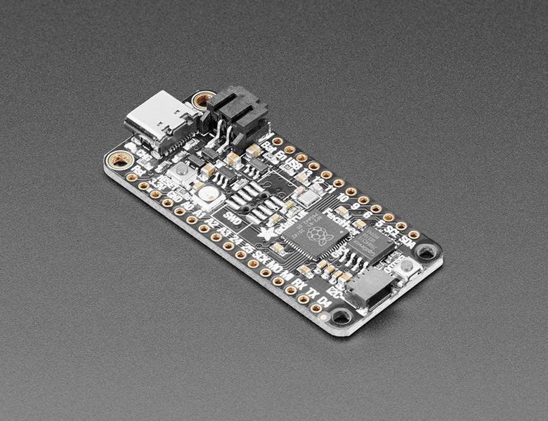
A new chip means a new Feather, and the Raspberry Pi RP2040 is no exception. When we saw this chip we thought “this chip is going to be awesome when we give it the Feather Treatment” and so we did! This Feather features the RP2040, and all niceties you know and love about Feather Measures 2.0” x...
Also I'm doing this on my MacBook and just finish other projects using CPX just fine but no success with new feather RP2040. I also tried to use my iMac to see if that made a difference but the RP2040 would not work at all when connected to iMac, power was there but LED does not illuminate, pushing BOOTSEL and reset resulted in nothing. Both computers use BigSur OS.
distant spade
floral moth
Also I'm doing this on my MacBook and just finish other projects using CPX just ...
anything in sudo dmesg?
floral moth
asks for password, I haven't a clue 😭
distant spade
you could try just plain dmesg
though I think it expects admin privileges
can you get to the serial connection?
floral moth
I used my admin password but it was not accepted. Oops, tried again it worked
(base) Maries-MBP-3:UTILS mariemeyer$ ls /dev/tty.*
/dev/tty.Bluetooth-Incoming-Port /dev/tty.URT1
/dev/tty.Maker-2546-RN-iAP-24 /dev/tty.URT2
/dev/tty.MariesAirPods-Wirelessi-1
floral moth
I get pages of text but nothing with RP2040, though the board is working as I did load PID4884_test.uf2
Interseting when I just us dmesg I get: Unable to obtain kernel buffer: Operation not permitted
usage: sudo dmesg and when I use sudo dmesg I get pages most of which is meaningless to me 😭
floral moth
@distant spade just to see I connected CPX to my MacBook and it too does not show up in serial connection. What has Apple done to me😩
frank quail
it's a good question, since I can see my neopixel trinkey and QT PY 2040 on a Big Sur macbook (intel)
distant spade
floral moth
<@!252717193496756235> just to see I connected CPX to my MacBook and it too does...
Try restarting your computer if you haven't. I did have times where I felt like my mac blacklisted my devices
floral moth
@distant spade Restart didn't seem to help
distant spade
hrm, weird
floral moth
@distant spade yes, very
distant spade
the bootloader works but circuitpy doesn't?
floral moth
@distant spade yes, I gather this is true as I can load the test uf2 file on the RP1-RP2 that appears on the desktop but when I load Circuitpython on RP1-RP2 it will disapear from the desktop but the CIRCUITPY drive does not appear and the RP2040 no longer functions till I reload the test file.
distant spade
have you tried the nuke uf2 file?
floral moth
no, I'm not aware of it
distant spade
that'd be worth doing
floral moth
how do I do that?
distant spade

Adafruit Learning System
CircuitPython for Pico will get you started in minutes!
floral moth
I'm looking in getting started pico....you bet me to it HaHa
@distant spade OK I nuked it, then download cricutpython to it but the result is the same, boot drive disappears and circuitpy drive never appears
distant spade
what is the example code that works? could you take a pic of the flash chip on it?
floral moth
PID4884_test.uf2, it's my understanding that this boards are shipped with this file
 distant spade
ya, that's baked into the rp2040 rom
I'm curious about the physical chip on the board
where does the test uf2 come from?
 distant spade
hrm, that looks right
the top right chip is the flash
does the status led do anything after CP is loaded?
floral moth
better view

this is how the sits after CP load
But when running the test uf2 13 flashes
floral moth
I'm referring to the PID4884 file, the green fades to other colors
distant spade
where did you get that file?
 distant spade
ah
my mind skipped the green button
I suspect that is pico-sdk code rather than circuitpython
floral moth
That's the issue I can't get CP to load. I was attempting to construct John Park's Touch Deck project
distant spade
I think it is loading if the neopixel is green after you copy CP over
floral moth
No it's just were the PID4884 program stopped, sometimes it's green, somtimes blue, and sometimes red, just depends at what point the program was interrupted and I don't think CP is every copied over as the cricutpy drive never appears.
distant spade
I doubt that it's failing to copy CP over
it might be that the flash isn't starting up correctly
you could try the 6.2.0 beta releases
there were some changes in the flash code so an older one may work
floral moth
OK, give me a moment
Can't seem to get there, I go to github for eariler CP but sends me to the https://circuitpython.org/board/raspberry_pi_pico/ which is where I statred but no option to select eariler version. Obviously I'm missing something
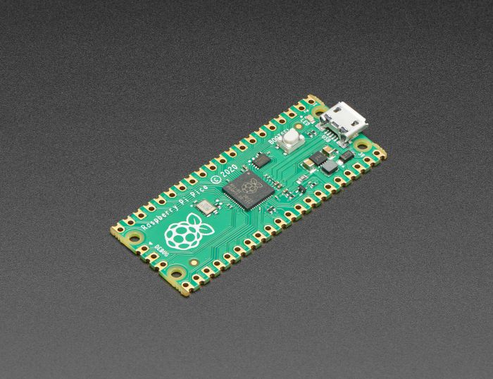
The Raspberry Pi foundation changed single-board computing when they released the Raspberry Pi computer, now they’re ready to do the same for microcontrollers with the release of the brand new Raspberry Pi Pico. This low-cost microcontroller board features a powerful new chip, the RP2040, and all...
frank quail
just to super triple double check, the file name for circuitpython is adafruit-circuitpython-adafruit_feather_rp2040-en_US-6.2.0.uf2 and is 499kB ?
distant spade
click "absolute latest" the S3 bucket has older versions too
ah! that'd do it too
the link from 10:28am this morning has the right circuitpython.org link
frank quail
you did link to the right cp.org page, so I assumed it was good, but please check
(I picked en_US, you might use another language, though try with en_US in that case, just to see)
floral moth
https://circuitpython.org/board/raspberry_pi_pico/ I don't see an option to select other CP versions
The Raspberry Pi foundation changed single-board computing when they released the Raspberry Pi computer, now they’re ready to do the same for microcontrollers with the release of the brand new Raspberry Pi Pico. This low-cost microcontroller board features a powerful new chip, the RP2040, and all...
https://github.com/adafruit/circuitpython/releases this page tells me to go to the link show above
GitHub
CircuitPython - a Python implementation for teaching coding with microcontrollers - adafruit/circuitpython
distant spade
the link above is not for the feather
frank quail
the link for the feather is https://circuitpython.org/board/adafruit_feather_rp2040/, you get to it by selecting the feather rp2040 from https://circuitpython.org/downloads
the file is adafruit-circuitpython-adafruit_feather_rp2040-en_US-6.2.0.uf2
floral moth
That's exactly were I was.
frank quail
6.2.0 beta versions are at the bottom: https://adafruit-circuit-python.s3.amazonaws.com/index.html?prefix=bin/adafruit_feather_rp2040/en_US/
(from the "Browse S3" link in the download page)
floral moth
WOW!!!! That worked I now have the circuitpy dive on my desktop. I use beta 4

Just an FYI

@distant spade Scott thank you so much, I learned quite a bit today
@frank quail Thank you so so much
frank quail
ah
small meteor
IF you run out of stuff to try, this will give you an interactive tty and blink the LED prior to connection:
https://github.com/wa1tnr/rp2040-arduino-basics-a/tree/main/monitor.d/monitor-hh-p/prebuilt_uf2.d/feather-rp2040.d
floral moth
cool
small meteor
13 wiggle toggles D13 several times.
quit exits and reflashes. ;)
fyi I never do see a drive in Linux, except RPI_RP2 and that's not mounted. Not in df report.
oops wrong - it does get mounted when I click on it. ;)
 $ sudo blkid | egrep sdb
/dev/sdb1: SEC_TYPE="msdos" LABEL_FATBOOT="RPI-RP2" LABEL="RPI-RP2" TYPE="vfat"
I see a 12-digit serial number in dmesg - in hexadecimal.
floral moth
Interesting since I've use sudo dmesg and the RP1-RP2 never shows nor does it appear when ls /dev/tty.* is used
small meteor
if 'aspberry' isn't in dmesg, then it's not showing (not in Linux anyway)
floral moth
Not in Mac either
small meteor
$ sudo dmesg | egrep "Raspb|alNum"
That picks up the branding and the serial number here.
Maybe if you install the C/C++ SDK it sets up some magic foo to make it all work smoothly.
 left vortex
hi
i have ordered rp pico
if i make an application with rp2040 with micropyhthon
later can i replace rp2040 wth another arm cortex mcu?
exotic moth
left vortex
later can i replace rp2040 wth another arm cortex mcu?
I think it depends on how specific your application is to the RP2040. In theory, yes, you could replace it. But it may not be a drop-in replacement, it might require some modifications.
left vortex
thank you @exotic moth i am thinking to make an AI application with camera and speaker
if i can manage to make it
exotic moth
The issue will be if you utilise any features of the RP2040 that aren't present in other ARM Cortex MCUs. If you're simply using it to run the hardware, you'll need to update pin names most likely, but that would be it.
exotic moth
I don't know MicroPython, unfortunately, so I can't be certain. If it works like CircuitPython in that sense, then yes, the same code should work, you would simply need to update the pin names to match the new hardware.
I believe it does work that way though.
The time the MicroPython cares about what hardware you have is when you tell it on what pins to look for your camera and speaker. So on Pico, GPIO24 and GPIO25, let's say. Then you want to use a SAMD51 or something, and maybe the pins are GPIO6 and GPIO7 or something. You would need to update that part of your code, but, in theory, that's all that would need updating. The rest should continue to work.
Unless you use the PIO feature of the Pico, for example, which isn't available on a SAMD51. Then it won't quite be that simple.
left vortex
should i choose circiutpython over micropython for better standardization?
exotic moth
That's entirely up to you. I don't think you'll get any better standardisation out of one over the other. If you're new to programming, CircuitPython is much easier to start with. If you're desperate for threading and interrupts, MicroPython is the way to go. Both have their strengths and it depends on your project. You should check out whether there is support (e.g. libraries) for your camera in either one, and if only one has support, that would answer your question easily. If they both have support for it, then you'll need to decide for yourself.
exotic moth
You're entirely welcome. Good luck with your project!
ebon lily
https://shop.pimoroni.com/products/pico-rgb-keypad-base
^ does anyone know if it is possible (at all) to use this with circuitpython?
im building my macro keyboard thingy and i want to write it all in circuitpython, because of the displayio libraries, and i can only find the micropython uf2 images or the c++ sourcecode :/

Connect a glorious, squishy, 4x4 rainbow-illuminated keypad to your Raspberry Pi Pico - perfect for making a custom USB input device!
 chrome osprey
ebon lily
https://shop.pimoroni.com/products/pico-rgb-keypad-base
^ does anyone know if i...
chrome osprey
ebon lily
https://shop.pimoroni.com/products/pico-rgb-keypad-base
^ does anyone know if i...
Unfortunately, there is no CircuitPython library for the TCA9555 which is used to read the buttons. However, looking at the Datasheet and the Pimoroni C++ code for MicroPython it shouldn't be too hard to write one if you're feeling up to it.
ebon lily
i first need to buy it to test, but i am willing to throw something together
small meteor
Just look at the example code they give (if they give example code).
Says APA102 those are DotStar RGB's.
Also says MicroPython library is provided.
This is likely to be a good starting point:
"Our Pico Keypad Pack offers a 4x4, squishy, RGB illuminated keypad for the Raspberry Pi Pico. The buttons are read via an i2c IO expander and the LEDs are APA102s driven by SPI."
ebon lily
all the source code is in c++, and they provide their own micropython uf2 file instead of the .mpy libraries
but i want to use circuitpython with it
small meteor
This looks like something related to porting it over:
https://github.com/pimoroni/pimoroni-pico/tree/main/micropython/modules/pico_rgb_keypad
For fifty cents I'm going to guess 'you have to port that code to work with CircuitPython'.
ebon lily
i already knew i would have to rewrite it
ebon lily
at least the code seems like it was made for humans to read
small meteor
(and somehow remain largely ignorant of the system I'm porting with, and to.) ;)
Basically you whack-a-mole until all compiler errors are gone. Then the code is correct from a compiler standpoint. May do little that's wanted, but it doesn't break the compiler.
Then figure out why it compiles but doesn't run correctly.
If your memory is good (human memory) you'll remember some or all of the places you just punted and did what your intuition told you to do.
Some of those guesses will be wrong.
diff helps quite a bit, there.
Shows you what you changed (old and new lines).
git diff is even better since it keeps a history of them, as the code evolves.
ebon lily
🤦
dang it bot
but yeah, i use git, a lot ...
(like, not at all)
it never cost me anything at all, oh no no
(until a bug in circuitpython literally destroyed over 10 hours of work)
small meteor
haha
Well I decided to. Didn't know or see the value; and then: I did.
I would say 'learn git or learn mercurial' due to a recent conversation I had.
But learn one of them.
ebon lily
git is good, but i see it as a huge barrier and a huge obstacle on development for this stuff
but that's a me-problem
small meteor
It's an investment and no, it won't write code for you. ;)
A lot of people just use git as a code repository, without ever using the commit-changes features.
Or branches.
"I didn't know when I started it was this kind of a time commitment."
ebon lily
i want to use git for it, but it's always a pain for me
small meteor
Heh. What do you use to interact with git .. a web browser?
ebon lily
i've used the webbrowser, i used vscode, i used the annoying windows program thingy, i used the bitbucket thingy... i can't really deal with it
small meteor
kattni wrote some tutorial materials related to git. Links should be in the git #channel.
I didn't like it much when I started using it. I still sort-of remember.
diff is more straightforward.
diff thisfile thatfile
diff is designed for a companion program called patch
The output of diff is applied to an older revision, using patch .. to update to the newer code.
ebon lily
yeah, i know that part
small meteor
Wikipedia article edit history uses a similar idea.
You can build a birdhouse with a hand saw and a hammer and a drill.
But you're not going to do cabinetmaking with just those tools.
Same is true of software-building 'tools'.
ebon lily
i just make it work, somehow
but when i get that board, i guess i will have to just bang my head till it works
small meteor
APA102 can be bit-banged - no driver required. i2c is hard to do poorly. ;)
ebon lily
well, it's not that hard
coming from someone that can screw anything
i basically, somehow, managed to destroy the flash of my pico pi trying to write a file to it
small meteor
The RPi Pico RP2040 board (and the clones) have a permanent bootloader.
small meteor
iirc the address of the loader is 0x0 or very low in the memory map, ending around 0x2000 or 0x4000 iirc.
Unless I'm mistaken.
ebon lily
well, i ruined it
the only way to make it operational was to nuke it with the nuke_flash.uf2 file
small meteor
and
ebon lily
i lost my code
ebon lily
over 10 hours banging my head to convert this:
https://github.com/adafruit/Adafruit_CircuitPython_HID/blob/master/adafruit_hid/keycode.py
to make it work with my keyboard and other non-us symbols

GitHub
USB Human Interface Device drivers. Contribute to adafruit/Adafruit_CircuitPython_HID development by creating an account on GitHub.
small meteor
Sure. So, get started doing it again before you forget all your insights.
In 30 days they'll be gone, probably.
I wrote a beautiful 8051 SMBus (i2c) driver program.
I do not have a copy of my own work, today. I would like to have it, but I never did publish it.
ebon lily
it was over 30 days ago
small meteor
('I wrote' here means 'I ported')
That's why I do things differently today than then. I tend to do the drudge work earlier, now, if I want to keep what I've earned.
ebon lily
oh, i do keep a copy of my work
it isn't worthy of being made public, yet
still need to write the keypad interface and display interface
small meteor
I think we're pretty far off-topic now. ;)
ebon lily
a little, yes
but it's related to the rp2040
btw, do you know how to do a soft-reset, like the ctrl+d on the repl, but without connecting to the repl serial?
small meteor
On RP2040 I build in a 'reflash' command using C/C++
I have not found a cold reset I can do.
reflash usually is suitable though I don't like that it exposed RPI_RP2 if I don't intend to update it.
ebon lily
by "cold reset" you mean, like if you pulled the power?
ebon lily
but on circuitpython?
small meteor
Haven't seen it.
Not really sure what's standard, there. Possibly the keyboard at the CDC/ACM interface.
ebon lily
well, i found the equivalent to pulling the power, but that's a bit too much for just restarting it
small meteor
The Pico RP2040 chip and supporting SDK seems to take great pains over just resetting the one thing you wanted to reset, inside the chip.
Kind of a strange way to do things on a $4 education sector chip target board. ;)
small meteor
Resets usually kill the USB connection at the REPL if you do them poorly.
NVIC_SystemReset(); is well-behaved in that regard.
ebon lily
eh, i dont care about that
i will be using the version 6.2.0 beta 3 with the 2 usb_cdc channels
i will have my c# program handle the 2nd usb_cdc channel, so, it's fine
just have to write it better
im a bit stumped on 2-way communication
small meteor
You might want to look at tinyusb because the author made extensive use of NVIC_SystemReset(); in CircuitPython.
ebon lily
i will have to look at it
got any ideas for 2-way communication over serial?
right now, i have it communicating by sending a "command" and receiving a "response" from c#
small meteor
Yeah I spend a lot of time thinking about serial. ;)
I think xmodem is sometimes leveraged if bit for bit is important (binary transfers).
Simple projects use ASCII representations of everything.
pyserial is used on a host PC to simplify implementation there.
I don't know if too many people use weird binary encoding via serial.
I mean if you wanted to send the message of the arithmetical quantity three you could do it by sending these bits:
0000 0000 0000 0000 0000 0000 0000 0011
ebon lily
im currently using json to send stuff
small meteor
gforth
hex  ok
33 emit 3 ok
decimal  ok
51 emit 3 ok
If you understand the json thing that's probably fine. I never did learn it (at all).
I personally would send 0x33 to the USART as part of a text stream.
(to send the message 'three' to another machine)
If I really needed binary transfer, I'd start with coding 'xmodem'.
That's what I've seen others do (several times) so I'm guessing it has merit.
ebon lily
nah, i just want it to be able to communicate with c# (or even javascript, in the future)
simple stuff
small meteor
The way I look at it, it all begins with two VT-100 terminals typing to each other on a closed loop.
ebon lily
like, sending numbers and simple utf-8 strings
small meteor
Both humans should be able to read what the other typed. It's all a substitute for typing by hand, by people, to other people. Everything else is derived from that base idea.
(teletypes)
When you start coding for this stuff you find out you need to convert strings to ASCII or to integer numbers.
The string data is often legible.
ebon lily
json handles it all for me
maybe i can send a null byte after the json string
im not sure how circuitpython would handle it
 valid kite
Just received a Feather RP2040. Unfortunately I failed to notice it had a USB-C and I don't have any cables. I have been programming a R-Pi Pico using the SWD interface with a Raspberry Pi 4. I'm trying to program the Feather RP2040 by powering it up from a Li-Ion battery and connecting to SWD via some wires that I soldered to the pads underneath. It doesn't look like the code is loading properly. No errors, but when I single step through the code simple variables that have been initialised to 0 are showing up as huge negative numbers. And also the code is not working. Am I scuppered until I get a USB-C cable?
Should say I'm using the C/C++ SDK in VScode
 plucky goblet
valid kite
Just received a Feather RP2040. Unfortunately I failed to notice it had a USB-C ...
plucky goblet
valid kite
Just received a Feather RP2040. Unfortunately I failed to notice it had a USB-C ...
You might check the pinout, as there might be pins corresponding to the USB Vin, dunno. That is the case on some other boards.
But of course you don't want to bypass the voltage regulator on a board unless your supply is safe and the correct voltage.
valid kite
I figured the battery would provide the power to the regulator instead of the USB.
plucky goblet
valid kite
I figured the battery would provide the power to the regulator instead of the US...
What I mean is that the USB connections might actually be mirrored as pins. There's generally a schematic posted somewhere where you could check this out.
small meteor
small meteor
QT Py RP2040 in stock.
 pine needle
#include <stdio.h>
#include "pico/stdlib.h"

int main()
{
    stdio_init_all();

    gpio_init(13);
    gpio_set_dir(13, GPIO_OUT);

    gpio_put(13, true);

    while (true) {
        puts("Hello!");
        sleep_ms(1000);
    }
    return 0;
}
How come that isn't lighting up the red led on an Adafruit Itsy Bitsy rp2040? It says on the overview page it has a Pin #13 red LED for general purpose blinking However, if I iterate through the numbers 1-30 and turn them all on, the led lights up. Am I being stupid?
pine needle
So apparently it's on 11
plucky goblet
I ran into the same problem and had to dig into the source code to figure out that the red LED on an Itsy Bitsy RP2040 is on pin 11, not 13. I don't know why Adafruit's web page says pin 13. I just tested this out to confirm that yes, the red LED is on pin 11 (e.g., "led = Pin(11, Pin.OUT)")
pine needle
Do they have like a complaint form so we can let them know?
plucky goblet
pine needle
Do they have like a complaint form so we can let them know?
If they're reading their forums hopefully someone will notice.
But you can always send an email to tech support. They're friendly in my experience.
 neon dock
You can also report issues from the learn guide, by clicking the "Feedback? Corrections?" in the left column of the learn guides
That goes to someone's inbox and gets tracked, which ensures that it gets looked at
neon dock
Still good to know if/when there's a next time! 🙂
pine needle
Indeed!
frank quail
there was a similar mistake in the Circuitpython board definition, probably a matter of the board being revised before release and the pages not updated
or maybe a matter of confusion between D13 and GP11
pine needle
I'm curious if anyone knows, what pin is the RGB led on for the Itsy Bitsy RP2040? Or am I just going to have to go digging again
 waxen aurora
Looks like GPIO17 from the schematic.
pine needle
Neat thanks
pine needle
Final question: Does Adafruit have a library for controlling the RGB LED from C/C++ OR Does the arduino library work for the rp2040 if I set it up right?
plucky goblet
pine needle
Final question: Does Adafruit have a library for controlling the RGB LED from C/...
They must, since I was doing that on my Itsy Bitsy M4 Express, which was programmed in C/C++. I think in the Adafruit docs on the Itsy Bitsy M4 Express you'd find an example file.
pine needle
Thanks for the tip!
small meteor
Feather 13 Itsy 11 Pico 25 qtpy 26
https://github.com/wa1tnr/camelforth-rp2040-b-MS-U/tree/dvlp-aa/17-camelforth-b.d/pico-examples/camelforth-b/include
(qtpy arbitrary; no inbuilt LED; put on A3 for hahas)
Crickit (SeeSaw) for CPX has NeoPixel code.
 bleak robin
Latest version of vscode has stopped loading the circuitpython extension so can't connect to my Pico. Does anyone have a solution?
 bleak kraken
do you have platformio installed in vscode? I had to remove it inorder for circuitpython to load
 tawny grove
I need some help in mapping wiring between the AS3935 lightning detector and the RPI Pico if anyone can help
eternal grove
You should be able to connect to it via SPI or I2C, depending on how it's configured.
small meteor
Can't power cycle QTPYRP2040 without losing /dev/ttyACM0 hello_world USB Debian AMD64 OS. ;)
So have to upload .UF2 every single time.
cloned fresh pico-sdk and
git submodule update --init
to update tinyUSB.
Other targets are fine.
(Feather RP2040, ItsyBitsy RP2040, Raspberry Pi Pico RP2040).
CircuitPython seems fine on same QTPY RP2040 target; recovers power cycle no issues.
New USB-C cable used (from Adafruit).
Nothing done with udev rules in Linux.
/dev/tty* does not enumerate /dev/ttyACM0 or anything close.
Did not check dmesg (at all ;)
Okay dmesg looking very interesting!
small meteor
zero effects on dmesg after removing the USB-C cable from the USB port of the PC, then plugging back in.
SESSION LOG, dmesg:
wary rampart
I have this program made in micropython with PIO instructions to try to play 1-bit audio through a buzzer, but the only thing I get is an OSError: 12:
import time
import rp2
from machine import Pin

# Define the one_bit program.
@rp2.asm_pio(set_init=rp2.PIO.OUT_LOW)
def one_bit():
    a = '1111111010110100101101010101000000000000000000000001111111111111000000000000101110111000000011111000000111111111110000001111111110000000000000101111111111000101111111111100111111111111011111110000000111111111111111111111111000000111111111111110101111111111111111111111111111111111111111000000000000011111111110000011111111011001111110000000011000001110000001111111111111111111111111011111111111111111111111111111111111111111111111111111111111000000000001111111111111111111111111111111111100'
    wrap_target()
    for i in range(len(a)):
        set(pins,int(a[i]))[1]
    wrap()

# Instantiate a state machine with the one_bit program, at 44100Hz, with set bound to Pin(15)(Buzzer on the rp2 GPIO)
sm=rp2.StateMachine(0,one_bit,freq=44100,set_base=Pin(15))

# Run the state machine for 5 seconds.
sm.active(1)
time.sleep(5)
sm.active(0)
@wary rampart you won't be able to do a for loop in a function marked with asm_pio
it's not really full python inside the function
wary rampart
How can you do bit-banging then?
In the documentation I do not see any clear and simple example of how to do them
small meteor
 $ git diff adafruit_qtpy_rp2040.h | cat
diff --git a/src/boards/include/boards/adafruit_qtpy_rp2040.h b/src/boards/include/boards/adafruit_qtpy_rp2040.h
index e3384fb..9b6496b 100644
--- a/src/boards/include/boards/adafruit_qtpy_rp2040.h
+++ b/src/boards/include/boards/adafruit_qtpy_rp2040.h
@@ -75,7 +75,7 @@
 #define PICO_BOOT_STAGE2_CHOOSE_W25Q080 1

 #ifndef PICO_FLASH_SPI_CLKDIV
-#define PICO_FLASH_SPI_CLKDIV 2
+#define PICO_FLASH_SPI_CLKDIV 4
 #endif

 #ifndef PICO_FLASH_SIZE_BYTES
 $ pwd
/some/path/to/camelforth-rp2040-b-MS-U/17-camelforth-b.d/pico-sdk/src/boards/include/boards
 $ date
Tue May 11 21:04:27 UTC 2021
 $
Doubling the clock divisor fixed my issue for now.
#define PICO_FLASH_SPI_CLKDIV 4
(Target survives removal of power; upon plugging in again, works as expected)
PR submitted here:
https://github.com/raspberrypi/pico-sdk/pull/401
 vagrant jetty
I am trying to find a library adafruit-blinka for a pi pico is there such a thing?
plucky goblet
According to the adafruit-blinka repository on PyPI (the official distribution) it is only available for non-Circuit Python versions of Python, so that'd mean CPython (on Linux) or MicroPython. The latter can run on an RP2040, the chip of the Pi Pico. Because the library is "owned" by Adafruit it's not part of the micropython-lib port but you can AFAIK just install the library onto your Pico from PyPI.
small meteor
In my PR I ask for a change in the clock divisor. Yet, ItsyBitsy RP2040 has the same QSPI flashROM chip, and it's recognized (by my Linux host PC, CDC/ACM) with a clock divisor of 2.
My PR asks for a divisor of 4 for qtpy RP2040.
(Going by CircuitPython source for the identity of that flash chip)
No, I'm not - sorry - going by what's in the pico-sdk include files for both target variants. Oops.
 $  ag W25Q64JVxQ ; echo ; pwd
boards/adafruit_qt2040_trinkey/mpconfigboard.mk
9:EXTERNAL_FLASH_DEVICES = "W25Q64JVxQ"

boards/pimoroni_tiny2040/mpconfigboard.mk
9:EXTERNAL_FLASH_DEVICES = "W25Q64JVxQ"

boards/adafruit_itsybitsy_rp2040/mpconfigboard.mk
9:EXTERNAL_FLASH_DEVICES = "W25Q64JVxQ"

boards/adafruit_qtpy_rp2040/mpconfigboard.mk
9:EXTERNAL_FLASH_DEVICES = "W25Q64JVxQ"

/some/path/to/circuitpython/ports/raspberrypi
 $
hi
I have a raspbery pi pico and ov7670 arduino camera
i would like to interface the camera with the microcontroller
but i could not find a solid tutorial which explain things for a newbie
my goal is to interface a cam with a microcontroller for object detection
it should be low cost solution
i have also stm32 black pill
would you suggest other microcontroller or camera for object detection?
small meteor
@left vortex May want to also look at Tensor Flow Light (not sure on the spelling of it).
That's in the Machine Learning range.
They had it, like, see a cat and say CAT but only if it was a cat.
My guess is: they train it a lot before it's any good at that task.
So it 'learns' with experience.
I may have some, or all, of that wrong. ;)
left vortex
Thank you @small meteor
I have some knowledge about tensorflow
I should use tensorflow lite for microcontrollers i suppose
What I would like to learn is how i can interface the camera with rpico so i can use the video for object matching
small meteor
@left vortex I've never done that (used a camera with a microcontroller) and I'm more of a 'you cannot do that' kind of person (been proven wrong many times).
They're doing video out with that chip, but, that's very different and not quite the same thing as normal video.
(still very impressive development in the MCU sector, from where I sit)
Pico is new on the market and innovators seem very attracted to it - it seems to me like a fast-paced new technology, building on what's already known.
The pio interface seems the strong attractor, here. It's something pretty unique, I think (don't know for sure).
 subtle bane
The Pico is an amazing little thing, but I'm not sure it has the horsepower to do video object matching... Pi certainly does
small meteor
also the XIP ('excute in place?') aspect is what drew my immediate attention to it.
iirc that's fundamentally different - a design that emphasises off-chip storage from day one.
I think the basics of visual matching would be about high-contrast changes in recognized shapes in an image.
subtle bane
Remote control cars!
small meteor
(above strongly edited for brevity - here's the original transcript):
https://termbin.com/41xo
storm heath
@left vortex There is a fairly new CircuitPython library for the OV7670 with an example for the pico in the examples folder https://github.com/adafruit/Adafruit_CircuitPython_OV7670 it is set up for an st7789 display. I am not aware of a guide for it, but you can ask questions here or in #help-with-circuitpython . The pin conections are in the example. The camera data lines are connected with D0-D7 on GP12-GP19. Only D0 is specifeid in the code since they must follow in that order.
I does work for displaying images. I have not tried using the images for anything.... yet
There is also an ov7670_simpletest.py that does not need a display, it just makes an "ascii-art" image in the REPL. It is a good place to start. Note: the pin assignments in the simpltest are not correct for the pico. They are for the grandcentral_m4 and must all be reassigned. Let me know if you want a working example.
storm heath
@left vortex here is the "simpletest" with the pins set for my pico. I just verified that it works.
@left vortex almost forgot, you do have to add pullup resistors to the ov7670 -- getting the guide
https://learn.adafruit.com/adafruit-ov7670-camera-library-samd51/hardware this guide shows how to modify the OV7670 camera
Or since you are just wiring it via jumpers for the pico, you can just put the pullups on a breadboard. the guide was really for plugging the camera into the grandcentral directly. I should not have made it sound so complicated. The main thing is the OV7670 camera does not have pull-ups on the SDA/SCL lines and you have to add them somehow...
left vortex
Thank you @storm heath
I was biased micropython over circuitpython
But now i see circuitpython have better support
storm heath
We like to think so 😉 -- Good luck!
 charred sluice
I have a Cortex M4 C-code project building with "make" and now I want to modify it to build for Raspberry Pi RP2040 Pico. The RP2040 code I'm integrating into my code uses a CMakeLists.txt and builds with VSCode.
I'd really like to have one single way of building and just specify the board type, so if it's reasonable to do, I'd like to just use make BOARD=XXXX.
Is it futile to try and convert from VScode and cmake back over to my current Makefile?
eternal grove
That's what I would do.
distant spade
charred sluice
I have a Cortex M4 C-code project building with "make" and now I want to modify ...
In CP, we just list the sources and include paths from the pico-sdk that we need
 hallow edge
hi everyone. i'm playing with the PIO on circuitpython and I'm stuck on something. I have a small PIO program which does "push" and I get the data using the readinto() method of statemachine. my understanding is that since the push pushes a 32bit word I should do readinto() into a bytearray(4). However, it seems that it only returns after four PIO push instructions. In other words, I wonder if there's some internal confusion between bytes and (32 bit) words on the rp2pio library
pine needle
std::vector<float> quat {-1, 0.7, 1, -0.5};
tud_hid_report(1, quat.data(), (sizeof(float) * quat.size()));
I'm trying to send an array of floats to the host device through tinyUSB but when I put the data I receive into https://www.scadacore.com/tools/programming-calculators/online-hex-converter/ I get wacky stuff. When I'm reading the data I get the hexadecimal string 0100 0080 bf33 3333 3f00 0080 3f00 0000 bf which I get from the python script
import hid
USB = 0xcafe
for dict in hid.enumerate(USB):
        print(dict)
        dev = hid.Device(dict['vendor_id'], dict['product_id'])
        if dev:
                f = open('./stuff', 'wb')
                f.write(dev.read(63))
                f.close()
``` Am I just putting the data in wrong and that's correct or am I doing something completely wrong?
Convert Hex values into Bytes, Ints, and Floats of different bit significance, Bit Endians, and byte significance for interfacing with unknown field devices
plucky goblet
I don't see an exact match for a channel for this question, but I was wondering if anyone knew if the new Itsy Bitsy RP2040 is a direct pin-for-pin replacement for the Itsy Bitsy M4 Express. I don't mean what's inside the CPU, but I've got the latter on a robot in a bespoke-wired socket and from the docs I can't see any pin-wise difference, so I'd like to just swap out the new RP2040 board to replace the ATSAMD51 one currently on the robot.
I.e., when Adafruit say it's an Itsy Bitsy form factor do they mean that they're pin-wise equivalent as well?
distant spade
hallow edge
hi everyone. i'm playing with the PIO on circuitpython and I'm stuck on somethin...
bytearrays are always 8 bit writes. check out array instead because it allows you to specify larger units
distant spade
plucky goblet
I don't see an exact match for a channel for this question, but I was wondering ...
Ya, probably. The pinout of the RP2040 is quite flexible
 ancient forge
Would this be right for a reset button on a pico (with also an input pin, I know RESET and RUN could technically be the same pin but it's making things easier to understand in this schematic)
 small meteor
@ancient forge Feather has 10k there and the rest of your circuit matches it.
Pin 26 is NOT_RUN (/RUN).
The signal on that pin is labeled NOT_RESET (/RESET).
(If they were inverted, the resistor would be a pull-down to GND)
NOT here means happens when brought low
/RESET means 'this thing resets when this pin is brought low'
ancient forge
Yeah, I understand what it means, I'm just glad I got it sorted, I think I ended up increasing it to a 10k one anyhow
small meteor
Active Low is a great term, here, as well.
plucky goblet
ancient forge
Yeah, I understand what it means, I'm just glad I got it sorted, I think I ended...
Yeah, I don't know why anyone would use 1K for a pullup resistor, draws a lot of current unnecessarily. 10K is pretty common.
charred sluice
distant spade
In CP, we just list the sources and include paths from the pico-sdk that we need
Fought with make for a couple of days and called a truce for now. Got too frustrated and wanted to get something compiling. Went back to cmake and VSCode and getting close to compiling again. Want to see something working and can then work on optimizing the toolchain when I have more patience…
 full saddle
First time I try to program in MicroPython (used to C/C++ and Arduino boards).

Any idea? Trying to read a BME280 sensor. Not sure which I2C pins to connect to. But I used these:

Nvm, used a different BME280 library. Works fine now.
 red wyvern
I'm just starting to look at building a GPIB (aka IEEE-488, HP-IB, etc) interface board, either to USB, Ethernet, or something else that could talk with a Linux box or RPi more easily than IEEE-488.
I'm curious - has anyone tried using the RP2040's PIO with that kind of bus? There are existing projects built around Arduino shield and Pi Hat form factors but an RP2040 could enable a much smaller form factro.
full saddle
Anyone using Arduino IDE for their RP2040?
When my serial monitor is open, I can't upload properly. Always have to close it and then upload, reopen. Anyone knows why?
 sleek sandal
full saddle
Anyone using Arduino IDE for their RP2040?
When my serial monitor is open, I c...
sleek sandal
full saddle
Anyone using Arduino IDE for their RP2040?
When my serial monitor is open, I c...
Woof. Ya, the Arduino IDE can be rough. I've experienced it before, that with different kinds of programmers selected, it often doesn't manage connection state to serial ports very well. If you're able, I've switched exclusively to PlatformIO and the VSCode plugin for it.
full saddle
sleek sandal
Woof. Ya, the Arduino IDE can be rough. I've experienced it before, that with di...
Thanks, found platformio quite overwhelming. Maybe I should give it a go again
sleek sandal
full saddle
Thanks, found platformio quite overwhelming. Maybe I should give it a go again
Ya, Arduino is this interesting middle ground, where if you don't need the more advanced functionality of Arduino/C, it is easier than most editors but as a software developer by trade, the editor is a bit painful for me to use.
VS Code + Microsoft just released their own Arduino plugin, might be worth a try https://marketplace.visualstudio.com/items?itemName=vsciot-vscode.vscode-arduino

Extension for Visual Studio Code - Arduino for Visual Studio Code
sleek sandal
full saddle
Thanks, found platformio quite overwhelming. Maybe I should give it a go again
I've played with it a bit, its interesting how it works. They end up calling the normal Arduino executable for most functions, VSCode is just a better code editor.
The benefit of that extension over the PlatformIO one, is it's more mainstream and will likely feel more familiar with terms and buttons and such.
full saddle
sleek sandal
Ya, Arduino is this interesting middle ground, where if you don't need the more ...
Yes, software dev myself. The new Arduino IDE 2.0 is better though.. still beta. Will try the MSFT Arduino plug-in
Thanks for the tip!
small meteor
I don't remember a problem with RP2040 and serial monitor Arduino IDE.
I'm reflashing so that automatically logs out the device ;)
But I usually 'double clutch' the two-button Adafruit boards (press BOOTSEL and tap RESET) if I don't have reflash going.
never really learned what 'double-clutch' means
small meteor
pico back in stock on Adafruit vending site. ;)
chrome osprey
ebon lily
i first need to buy it to test, but i am willing to throw something together
I've finally gotten hold of a RGB Base and I've written a TCA9555 library which will read the keys. The leds are controllable with the normal DotStar library. It's only on Github at the moment (not PyPI or Readthedocs.)
https://github.com/lesamouraipourpre/Community_CircuitPython_TCA9555
There's an example which reads the keys and controls the LEDs.
Any feedback would be appreciated.

GitHub
Library for TCA9555 Low-Voltage 16-Bit I2C and SMBus I/O Expander on CircuitPython. - lesamouraipourpre/Community_CircuitPython_TCA9555
ebon lily
😮
i need to test it, once i get a board
yes, still havent bought the keyboard thingy
keypad
but i will try it as soon as i get it
i was reading it and it does look really cool
exotic moth
chrome osprey
I've finally gotten hold of a RGB Base and I've written a TCA9555 library which ...
This looks really excellent!
exotic moth
Excellent use of register.
 raw monolith
Hello everyone! I need a little help with a project I'm making with an RP2040
I want to know what would be the best way to power the RP2040 without using a PC or battery
ebon lily
using a pc? just plug an usb cable
 ebon lily
if im not mistaken, either 39 or 40 will be for 5v in
let me check
yeah, seems that pin 39 takes 1.8-5.5v
raw monolith
alright, thank you!
ebon lily
you're welcome
 coral wyvern
Hello everyone, I got a question. I want to control multiple small oled displays, and for what I want to make it seems all the displays are controlled via SPI. Now based on what I've read, could I use one spi out to send data to all of them, and then use a general gpio as the cs on each one so when I want to send data to only one of them I just pull that one's cs high and leave the other ones low (or vice versa as appropriate, I have no idea what I'm doing. I'm new to all of this, and have been learning python for a month and circuitpython for 2 weeks). If that's not how that works could someone point me in a correct directiom of a rabbit hole to go down. Thank you
small meteor
@coral wyvern it may be necessary to experiment with at least two display units. As far as I know, you've described it correctly. /CS (or just CS) is probably used to tell the bus which unit is being talked-to.
I think it has to be dynamically operated - I don't think you can get away without /CS connected to GPIO.
(say by tying it to GND or to Vcc).
coral wyvern
i figured it had to be gpio, i just wasnt sure if there wasnt something special like it NEEDED to be a particular pin or any gpio that can be set to output and be high or low will work. I just wanted to make sure I'm not missing something cause it seems like everyone else who's done something similar has a much more complicated solution. Maybe as I try this i'll find out why. Needless to say having some confirmation that I'm understanding it correctly just means I need to start trying stuff out and see how it works.
which in turn means maybe I can make my idea to make my own version of the NKK lcd switches happen and make a macropad like streamdeck where each switch has it's own 96x64 rgb oled
waxen aurora
coral wyvern
i figured it had to be gpio, i just wasnt sure if there wasnt something special ...
Yep, your understanding is on the level. Some chips have dedicated pins for CS which is under the control of the SPI peripheral, but it's almost always fine (or even preferred) to use a general GPIO for that instead and have the software layer handle which device is being selected.
coral wyvern
Thank you @waxen aurora . Admittedly, now that I know that it should be possible, I have a million other ideas and questions running through my head of the possibilities.
small meteor
@rapid stag I have one of each (differently date-coded) flash chip.
My copy of the QT Py RP2040 has the problem flash chip; the ItsyBitsyRP2040 I have uses the non-problematic flash chip
 rapid stag
small meteor
<@!329766224093249548> I have one of each (differently date-coded) flash chip.
...
rapid stag
small meteor
<@!329766224093249548> I have one of each (differently date-coded) flash chip.
...
thanks, that is very interesting; there might be other components whose specs have changed between runs, such as the crystal or even the RP2040 (though it is the same version). The more data points we have the better!
small meteor
;) I like having both the problem and non problem chips on hand. ;) It's fun.
rapid stag
I have the same: two qt py's and one Itsy with same data code, all are fine; one qt py with other data code, problematic
small meteor
I didn't want to clutter up the PR with this so I figured I'd let you know here, in case you need a tester for some reason.
rapid stag
@small meteor do you actually see a problem with the possibly problematic QT Py? Does it load and run CircuitPython just fine?
small meteor
@rapid stag Yes it runs CircuitPython without issue, but won't run the hello_world in pico-examples in pico-sdk repo.
(Does not enumerate USB except when dragging and dropping the .UF2 for the pico-sdk hello-world example program).
(so it runs exactly once - will not run a second time when power is cycled)
rapid stag
that is similar behavior; you could try building the hello-world with that one line change to xosc_init() and see if it makes any difference
does hello-world work fine on the itsy?
small meteor
iirc I had no problems with the Itsy at all.
I'm running a CamelForth on the targets which challenges them more than hello-world does. ;)
I set the clock divisor to 4 (from 2) for qtpy and that cleared up my issue.
(itsy didn't need this change, nor did feather or Pi Pico RP2040)
small meteor
I don't know where to make the xosc_init() change but I'll look for it.
small meteor
 $  ag xosc_init | cat -n
     1  src/rp2_common/hardware_clocks/clocks.c:134:    xosc_init();
     2  src/rp2_common/hardware_xosc/include/hardware/xosc.h:28:void xosc_init(void);
     3  src/rp2_common/hardware_xosc/xosc.c:16:void xosc_init(void) {
@rapid stag
Adafruit CircuitPython 6.2.0-58-g17955ba5e-dirty on 2021-05-18; Adafruit QTPy RP2040 with rp2040
This enumerates /dev/ttyACM0 on Debian amd64 even after CP2104 Friend has enumerated and has been connected-to in an active session.
That's fairly robust behavior.
The ItsyBitsy RP2040 fails this test - won't enumerate unless I unplug CP2104 friend, first. ;)
It's running an Arduino IDE program for RP2040 (several days since buring the firmware)
rapid stag
there is an erratum about that in the RP2040 datasheet, I think
about multiple devices on USB
small meteor
Right but why does your circuitpython not also fail.
rapid stag
I'm not sure there's a software workaround, but we might have enabled it if there is. It may also be due to some delay, or differences in what the particular version of tinyusb is doing
small meteor
Okay - yeah there was a software kludge and I've tested it. My (human) memory is poor on this. ;)
rapid stag
there is a separate thing about GPIO15, but I think that's a different erratum
small meteor
The best I got was I could enumerate two /dev/ttyACM* devices but if I connected to either one the other would not enumerate.
rapid stag
there have been many recent changes re RP2040 in tinyusb: https://github.com/hathach/tinyusb/pulls?q=is%3Apr+is%3Aclosed+rp2040
small meteor
So to get both enumerated and active in a terminal I had to plug both in, see that they enumerated, then connect one at a time. That did work.
My workaround was the GPIO15 thing iirc.
Anyway - main point was your CircuitPython in that .zip in the forum seems quite robust comparatively.
rapid stag
ah, you were testing with that, got it. Keep an eye on these issues, lots of questions to answer here
small meteor
@rapid stag Thanks for all of this.
 plush moon
Has anyone been able to build and flash code to the rp2040 feather board just using C and Cmake? (I assume yes but I am trying to move my dev setup from the pico to the feather and I am having trouble, it builds fine but flashing with picoprobe or using the uf2 file makes the board crash)
plush moon
mainly asking how other people are building there code for the feather rp2040 because i am having issues
the differences between compiling for the base pico board and feather would be helpful too but ill thumb through that git repo and see if i can fix my problem
 heady estuary
I'm wondering if anyone else has been having significant problems flashing their rp2040 feather via the arduino ide. I was only able to flash it once since I got it, every time both prior and since then it gives a generic error and fails to upload. It persists across my windows and arch machine. Dragging the uf2 file over from the temp directory into the bootloader directory works most of the time, although anything other than a simple blink sketch doesn't seem to work.
I haven't really done much with microcontrollers before so I'm a bit lost on what the issue is
 keen iron
Good evening everyone, a quick question if I may? I'm trying to build my first project with a raspberry pi pico... an HC-SR04 ultrasonic sensor requires 5V and a 3.3V split voltage which runs from VBUS, but I also wish to use the MAX98357 I2S Class-D Mono Amp which requires 3.3V... Can I run that from the 3V3(OUT) and have them work together from the one micro USB input or would I need to add an external breadboard power supply? Oh and two diffused red LED, so sensor to light and sound.
small meteor
@plush moon
$ cmake .. -D"PICO_BOARD=adafruit_feather_rp2040"
The original Raspberry Pi Pico RP2040 is the only target that does not need something like this.
Everything else needs to be told what $PICO_BOARD is.
Look in pico-sdk/src/boards/include/boards for each associated .h file for any target board.
Take that filename and drop the .h from it.
That's how I got the correct parameter for:
cmake .. -D"PICO_BOARD=adafruit_feather_rp2040"
There is an include file in that directory, named
adafruit_feather_rp2040.h
@heady estuary After building an .UF2 file in the Arduino IDE, I copy it to the mounted RPI_RP2 drive using the operating system itself.
I don't use the Arduino IDE to automate this, in any way.
@keen iron I have not at all looked at what the RPi Pico RP2040 board can do in the way of supplying power to sensors and such.
Almost all boards on the market provide at least 100 mA at 3.3 VDC to peripherals like that sensor, as well as VUSB which is passed from the host PC and is 5.0 VDC.
The RPi Pico RP2040 target's power supply section is reproduced in the scrollback of this #channel if I'm not mistaken.
It's also in the factory PDF.
(I checked; it's not in the scrollback of this channel, unless I (somehow) missed it)
Looks like pin 36 is 3.3 out
38 is ground (and several others are as well)
VBUS is on pin 40
4.4 Powerchain in the PDF.
Basically says VBUS feeds to VSYS through a schottky diode.
RT6150 buck/boost transforms VSYS to a fixed 3.3VDC.
heady estuary
small meteor
<@!211324975544664064> After building an `.UF2` file in the Arduino IDE, I copy...
Alright, that's what I've been doing. I'm not sure why it fails in the ide, but if copying it manually works, it works
small meteor
@heady estuary I just didn't want to spend the time tracing down if/why it should work through the IDE.
I had a similar problem with STM32duino which I also circumvented.
The hardware usually is on the market way before SDK support is full and complete.
Two years from now it'll be like 'what problem?'
heady estuary
Now I just have to figure out how to get my oled feather to work...
Running the example oled sketch leaves me with a black screen :/
small meteor
I've never once run an OLED. The regular LCD character displays you could adjust the contrast and figure out if anything at all was being received by the LCD controller chip.
heady estuary
I have no problem running the oled in circuitpython, only when I'm trying to use it with arduino. At first I thought maybe I was missing a library or maybe something wasn't connected right but it just doesn't seem to want to work with arduino
small meteor
Oh okay if it's wired correctly and works with any software at all then it is a software issue not a wiring issue.
heady estuary
It does spit out a bunch of errors about the adafruit libraries using deprecated commands, I can't post it right now because I'm not at home though
maybe it's just an rp2040 problem, considering it's still pretty new
small meteor
A lot of those libraries use well-known interfaces; they may make assumptions about pins.
I would find a library that does work and examine why it works.
Obviously it'll be one that does nothing I want done, but them's the breaks. ;)
heady estuary
That's always how it goes
small meteor
Look at some of the well-known libs and ask the question: how do they work on very different platforms. How were they ported.
I mainly work with the core so I don't encounter this issue very much.
heady estuary
Serves me right for expecting new hardware to be fully ironed out :P
small meteor
;)
The stuff they are working on for RP2040 is compelling.
I've learned to follow what they're up to ;)
heady estuary
oh and on the note of flashing via the ide
I've found that flashing it with Pico selected with mbed, it just works. Of course the code doesn't run at all, but it flashes without any problems. The exe that it's using to flash mbed must be doing something veery different than what the python script is doing
Same if I flash it as an rp2040 Connect. It just flashes, no problem
small meteor
I did learn exactly how the Arduino IDE launches a shell script to do the STM32F405 Express upload thing, iirc.
If you read the logs and work at it hard enough, it ought to work.
Get it working on the command line perfectly.
heady estuary
That's hopeful
Ill take a peek at it. I'm not the best python programmer in the world but hopefully it's not too difficult to understand what it's doing
and why it's having a problem
small meteor
In Linux it was pretty deep under the ~/.arduino15 tree
heady estuary
It works fine up until it disconnects the board to reboot it into bootloader, then it seems to forget what it's flashing to
whereas the exe doesn't have a problem with that
Anyways thank you, I'll update if I dig anything up
small meteor
.arduino15/packages/STM32/tools/STM32Tools/1.4.0/tools/linux/stm32CubeProg.sh
Pretty sure I messed with that to get it to go.
So that's fairly deep under ~/.arduino15
I don't have any logs to look at since I directly copy the UF2 and it's done. ;)
So I don't know what the Arduino IDE tries to do - or if it would succeed or not. ;) lol never even gave it a chance to fail. ;)
(I was already copying the UF2 using the same method, for C/C++ SDK work, so there was no real change in my workflow).
heady estuary
I'll paste it here when I'm home, it's a bit strange
small meteor
;)
Turn on any warnings and messages in the IDE.
I think I saw some openocd stuff for this but I don't know how that works.
heady estuary
Right so I have part of the error that Adafruit_SH110X spits out:
H:\Documents\Arduino\libraries\Adafruit_SH110X\splash.h:6:5: warning: 'B00000000' is deprecated: use 0b00000000 instead [-Wdeprecated-declarations]
    6 |     B00000000, B00000000, B00000000, B00000000, B00000000, B00000001, B10000000,
      |     ^~~~~~~~~
In file included from C:\Users\{username}\AppData\Local\Arduino15\packages\rp2040\hardware\rp2040\1.5.1\cores\rp2040/api/ArduinoAPI.h:26,
                 from C:\Users\{username}\AppData\Local\Arduino15\packages\rp2040\hardware\rp2040\1.5.1\cores\rp2040/Arduino.h:30,
                 from H:\Documents\Arduino\libraries\Adafruit_GFX_Library/Adafruit_GFX.h:5,
                 from H:\Documents\Arduino\libraries\Adafruit_GFX_Library/Adafruit_GrayOLED.h:29,
                 from H:\Documents\Arduino\libraries\Adafruit_SH110X\Adafruit_SH110X.h:27,
                 from H:\Documents\Arduino\libraries\Adafruit_SH110X\Adafruit_SH110X.cpp:39:
C:\Users\{username}\AppData\Local\Arduino15\packages\rp2040\hardware\rp2040\1.5.1\cores\rp2040/api/Binary.h:45:3: note: declared here
   45 |   B00000000 DEPRECATED(0b00000000) = 0,
      |   ^~~~~~~~~
I assume it's going through an array because it keeps repeating this, advancing one space at a time.
It ends with
  516 |   B11100000 DEPRECATED(0b11100000) = 224,
      |   ^~~~~~~~~
H:\Documents\Arduino\libraries\Adafruit_SH110X\Adafruit_SH110X.cpp: In member function 'virtual void Adafruit_SH110X::display()':
H:\Documents\Arduino\libraries\Adafruit_SH110X\Adafruit_SH110X.cpp:281:49: warning: narrowing conversion of '(176 + ((int)p))' from 'int' to 'uint8_t' {aka 'unsigned char'} [-Wnarrowing]
  281 |       uint8_t cmd[] = {0x00, SH110X_SETPAGEADDR + p, 0x10 + (page_start >> 4),
H:\Documents\Arduino\libraries\Adafruit_SH110X\Adafruit_SH110X.cpp:281:59: warning: narrowing conversion of '(16 + ((int)(page_start >> 4)))' from 'int' to 'uint8_t' {aka 'unsigned char'} [-Wnarrowing]
  281 |       uint8_t cmd[] = {0x00, SH110X_SETPAGEADDR + p, 0x10 + (page_start >> 4),
      |                                                      ~~~~~^~~~~~~~~~~~~~~~~~~
H:\Documents\Arduino\libraries\Adafruit_SH110X\Adafruit_SH110X.cpp:282:35: warning: narrowing conversion of '(int)(((unsigned char)((int)page_start)) & 15)' from 'int' to 'uint8_t' {aka 'unsigned char'} [-Wnarrowing]
  282 |                        page_start & 0xF};
      |                        ~~~~~~~~~~~^~~~~
I'm not sure if this is more suited for here or #help-with-arduino
The program compiles fine, but when trying to upload, I get this:
Global variables use 12868 bytes (4%) of dynamic memory, leaving 249276 bytes for local variables. Maximum is 262144 bytes.
C:\Users\{username}\AppData\Local\Arduino15\packages\rp2040\tools\pqt-python3\1.0.1-base-3a57aed/python3 C:\Users\{username}\AppData\Local\Arduino15\packages\rp2040\hardware\rp2040\1.5.1/tools/uf2conv.py --serial COM9 --family RP2040 --deploy C:\Users\{username}\AppData\Local\Temp\arduino_build_239174/OLED_featherwing.ino.uf2
An error occurred while uploading the sketch
and nothing after that
if anyone has insight on this, please share
eternal grove
The messages give the recommended fix: basically you'd replace each instance of B11100000 with 0b11100000
Since there are lot of different ones, I would probably write a short Python program to do them for me.
heady estuary
I just went and used notepad++ to batch replace anything that started with B with 0b
while those errors are now gone, it still doesn't run on the feather 🙃
eternal grove
It compiles though?
heady estuary
eternal grove
It compiles though?
yeah it does (late reply, oops)
it just doesn't actually run at all, as far as I can tell
visually, anyways.
no serial output either
It must be something with one of the libraries included in the oled example because other included examples (for blinking the led or running a multithreaded program) work without issue
small meteor
@heady estuary Is there some reason why you're not solving the problem you're solving? ;)
C:\Users\{username}\AppData\Local\Arduino15\packages\rp2040\tools\pqt-python3\1.0.1-base-3a57aed/python3 C:\Users\{username}\AppData\Local\Arduino15\packages\rp2040\hardware\rp2040\1.5.1/tools/uf2conv.py --serial COM9 --family RP2040 --deploy C:\Users\{username}\AppData\Local\Temp\arduino_build_239174/OLED_featherwing.ino.uf2
An error occurred while uploading the sketch
So there's a tool provided by rp2040 foo vendor that uses python3.
uf2conv.py is something to take some other input (possibly .bin) and make it into a UF2 file.
Serial was specified as COM9.
The --deploy switch points to a UF2 file. Ostensibly it even exists.
So I would check manually that the UF2 got built and uploads and runs on the target.
If it does, it's a matter of automating that process.
You may even find the text of that error message in a very specific file; you can edit that file and change the text of that message, to remove all doubt that it is that very file that is reporting the error encountered.
small meteor
heady estuary
I'm wondering if anyone else has been having significant problems flashing their...
anything other than a simple blink doesn't seem to work.
That'll be the programmer - yourself. ;)
If blink's working try something else that's kind of simple.
Do not skip over steps.
This is the Arduino IDE and not the C/C++ toolchain.
This program is compiled in the Arduino IDE, for the RP2040 chip:
https://github.com/wa1tnr/rp2040-arduino-basics-a/tree/main/monitor.d/monitor-hh-p
This one's fairly basic and not overly commented or with so much cruft left behind:
https://github.com/wa1tnr/rp2040-arduino-basics-a/tree/main/_test-a.d/itc-forth-aa
The 'reflash' there will present as RPI_RP2 drive in Linux. I don't know if other OS's use a different name (doublt it).
From there just drag and drop to reflash (using a UF2).
(does in software what other have to do in hardware, to start a reflash)
heady estuary
small meteor
So I would check manually that the UF2 got built and uploads and runs on the tar...
uf2 does get built, and they run when copied manually
heady estuary
small meteor
That'll be the programmer - yourself. ;)
And I'm using pre-made examples. Had I written it myself, I'd know who to blame :P
the specific example I'm using is from the Adafruit SH110X Library, called OLED_featherwing
heady estuary
small meteor
This one's fairly basic and not overly commented or with so much cruft left behi...
This seems to have worked, it prints "A" several times to serial and then puts the board into bootloader mode. From there, I was able to drag a .uf2 file I made (which blinks the on board neopixel RGB) into the RPI_RP2 drive, which flashed and ran without issue. So that works!
I tried to run the example oled sketch again, though, and I was able to get serial output but nothing to display on the oled
at least I know the neopixel works ¯_(ツ)_/¯
small meteor
heady estuary
This seems to have worked, it prints "A" several times to serial and then puts t...
So that's great!
RP2040 Feather
I have one of these and found it good to work with.
LED on GPIO13 and NeoPixel on GPIO16 (Feather variant doesn't need a 'power pin').
Flash is to 0x10000000 plus 0x7FFFFF.
heady estuary
yeah I had to look at the board schematic to figure out which pin it was since it's pretty much undocumented
small meteor
CamelForth will run on FeatherRP2040:
I didn't add WS2812b support to CamelForth just yet.
heady estuary
do you think I should try that out too
small meteor
Yeah sure. It'll give you confidence that the target's working nicely.
Interacting with the target in real time is a powerful convincer, I think.
heady estuary
I'm beginning to think that the SH110X library just hasn't been updated for the rp2040 feather, but I don't know because I haven't seen or heard anyone else using it with that specific feather
so there's a very real chance I'm just very incompetent :)
small meteor
No your first guess sounds correct.
I think you were on Arduino IDE (I can't remember obvious things anymore ;)
that's the build script I use to make a CamelForth UF2 for Feather RP2040 using C/C++ SDK toolchain.
There should be at least one prebuilt UF2 ready to download.
Which is probably more to the point for your needs.
If you type
5 3 * .
it should say either
  F
ok
or:
  15
ok
The dot just prints what's on top of the Forth stack.
5 and 3 are literals.
F or 15 is the answer and depends on the base you're in (decimal, or hex).
It's pretty much an RPN calculator when used this way.
One of these two should be in the basic Forth dictionary:
https://github.com/wa1tnr/camelforth-rp2040-b-MS-U/blob/main/17-camelforth-b.d/pico-examples/camelforth-b/pico-hw/pico-LED/pico-LED.c#L26
They both seem to be. ;)
heady estuary
alright, thank you
Im doing a bit of spring cleaning right now so my workstation is a bit covered in junk (but when is it not) so I'll have to get back to you later on the outcome
small meteor
So just type 'blink' at the ok prompt.
heady estuary
I appreciate your patience will all of this, though!
small meteor
pip should be a very terse blink and 'blink' should be a stronger longer duration blink.
;)
: tryme 8 delay pip 12 delay blink 8 delay blink 12 delay pip ;
heady estuary
will do
small meteor
The colon begins a definition in forth and the semicolon ends it.
'tryme' is the name of the new defintion (called a 'word').
I'm often not here for a few days so I'll see any responses only when I return. ;)
heady estuary
that's fine, I greatly appreciate the help
heady estuary
🏳️🌈⭐
small meteor
You can get them chips for a buck.
Today, we’re announcing the logical next step: RP2040 chips are now available from our Approved Reseller partners in single-unit quantities, allowing you to build your own projects and products on Raspberry Silicon.
It's a nice chip!
eternal grove
Looks home-solderable too, which is nice
ancient forge
I've heard LadyAda talk about using the Boot Select button on RP2040 boards as a GPIO but how does that work? whats the circuitry used?
storm heath
@ancient forge See the last comment in this discussion https://www.reddit.com/r/raspberrypipico/comments/lymezt/say_i_want_to_use_the_boot_select_button_as_a/. It is not encouraging.... As documented in the Pico Datasheet. The BOOTSEL button is not connected to RP2040 GPIO at all, it is connected to the Chip Select (/CS) pin of the W25Q16JV flash memory chip. The /CS pin enables and disables the flash chip. The button disables flash boot, enabling USB boot.
ancient forge
nono, not the pico
She said Pimoroni did it with one of their boards, and she was doing it with her KeyBoar
storm heath
Ah sorry, I misunderstood.
small meteor
I've forgotten but probably one 1N4148 signal diode and maybe a resistor.
When she publishes the schematic it's gonna be something simple like that. ;)
 stone tusk
Can we built a fido2 u2f key using rp2040 ie. QtPy or rp pico
 dusty hedge
hi guys, I have a pio question I can't make forward progress on by googling: I have two encoders attached to my rp2040 feather, and I have pio based encoder reader that works fine if I read from one or the other - but when I read from both, it seems like they start interfering with each other, and either no data comes out, or it comes out garbled/twice. is there something I have to do to make the statemachine instances properly separate? - https://pastebin.com/SXj93KgD - maybe I'm missing something obvious about oop in python, but I hope not.
dusty hedge
dusty hedge
hi guys, I have a pio question I can't make forward progress on by googling: I h...
hi @dusty hedge , I think I see your problem: your readinto is blocking, so the code will just wait for alternating encoders to have data, and that's why they seem to be interfering. try to add a in_waiting check at the start of read_encoder and you should be good!
small meteor
hey guys, i have a question here, does someone have experience use C++ for adafruit feather rp2040 board? i saw there are almost none info on the internet.
also can we actually use the PICO C/C++ SDK for Adafruit feather rp2040 ? bcs when i click the C/C++ support link on the data sheet, it goes to github for PICO.
thank you 🙂
plucky goblet
small meteor
hey guys, i have a question here, does someone have experience use C++ for adafr...
I think the fact that the chip and the boards that use it are all very new means that everything is still a bit confused. The release of the RP2040 has been met with a lot of enthusiasm, and there's lots of versions (carrier boards) in different form factors. But if a board is using the RP2040 you can generally use the SDK to program it. There might be hardware unique to a specific carrier board, like battery management or an RGB LED or something, but the RP2040 is what you're programming, so I'd say the SDK should be fine.
I've got a RPi Pico and a couple of Itsy Bitsy RP2040s that I haven't had time to actually begin playing with... yet! 😆
small meteor
@small meteor
cmake .. -D"PICO_BOARD=adafruit_feather_rp2040"
(from pico-examples/build directory)
Do the same for any of these targets (replacing what you see, above):
adafruit_feather_rp2040
adafruit_itsybitsy_rp2040
adafruit_qtpy_rp2040
arduino_nano_rp2040_connect
none
pico
pimoroni_keybow2040
pimoroni_pga2040
pimoroni_picolipo_16mb
pimoroni_picolipo_4mb
pimoroni_picosystem
pimoroni_tiny2040
sparkfun_micromod
sparkfun_promicro
sparkfun_thingplus
vgaboard
Remove .h from these filenames to obtain the string to build for any of them:
https://github.com/raspberrypi/pico-sdk/tree/master/src/boards/include/boards
small meteor
small meteor
<@456226577798135808>
```bash
cmake .. -D"PICO_BOARD=adafruit_feather_rp2040"
``...
thank you, will try it soon 🙂
still confuse with what is that but let's see hehe
 red bay
small meteor
hey guys, i have a question here, does someone have experience use C++ for adafr...
red bay
small meteor
hey guys, i have a question here, does someone have experience use C++ for adafr...
Yes you can. It is too bad that there is such a stress to direct people to the various Pythons, but I understand why. Still, the GPIO numbering would have been nice on the Adafruit boards
 wet mulch
Hello makers,
I've a question about HID with Pico.
I'm working on a project nowadays. I use Raspi Pico as a mouse on circuitpython with adafruit hid library.
I would like to know status of mouse's left clik. Is that possible? If yes how can I do that?
small meteor
@small meteor It's the same idea as CC=gcc make
You're setting a string into the environment, essentially. In this case, you're choosing a non-default target (There are so many targets to build for; this is the mechanism to select which target platform is used to compile subtle differences, for).
So some targets may only have 4 megabytes of flashROM; others, 8 mb.
 wind pier
Hi! I have an adafruit_feather_rp2040 and an adafruit_qtpy_rp2040 and a featherwing oled 128x64 and would like to know how to use the 3 buttons A, B, C in the oled. Would you help me? I'm using from CircuitPython.
eternal grove
The waveform generator tutorial uses the buttons, the code that does so is covered here https://learn.adafruit.com/waveform-generator/code

Adafruit Learning System
This device has many names: function generator, waveform generator, and signal generator. As we all know... you can't stop the signal.
wind pier
Thanks!
small meteor
hey peeps 🙂
i want to continue my question installing c++ for adafruit feather rp2040.. do we need spesific file to install it like circuit python or no. bcs i tried to follow the installing c++ from the pdf and tried to put my blink.uf2 but suddenly my board just turn off, didnt connected and no blinked led.
thanks 🙂
eternal grove
Normally you don't "install" C++, just compile the code and upload it to the board.
small meteor
ah yeah that's what i mean. but now it's fine. i tried @small meteor solution and all good. thanks 🙂
 gusty cloud
I'm experimenting with gpio on Pico, and when I send an output pin low, gnd and that pin doesn't have continuity when powered by vsys
But it has continuity when powered by usb
Why?
Or is it actually metering non zero voltage...
eternal grove
Did you try continuity both ways?
gusty cloud
oh, interesting, it's because it's 55ohms and not 0ohms