#help-with-hw-design
1 messages · Page 42 of 1
 fast tundra
 tough matrix
yep, decided to make my twitter handle less personal
fast tundra
tough matrix
bookmarking
fast tundra
But I love your project, btw.
I love seeing more open source stuff in robotics, especially aimed at education.
tough matrix
I have been coaching First Tech Challenge team for like 10 years
fast tundra
It's so frustrating how FIRST's hardware and software platforms are closed source.
fast tundra
Oh god it's SO expensive.
tough matrix
were you part of FRC/FTC?
fast tundra
Between the power distribution module and the roborio that's like $1,500 of a teams budget. And you really need two so you have a backup.
tough matrix
We are community team meeting in a basement
so FRC is not an option
fast tundra
Nice.
tough matrix
FTC is more manageable, but still not cheap
 misty escarp
seems like a good space for an open source community to disrupt
i don't love the term disrupt but it's appropriate here
tough matrix
somehow, there are hundreds of "robotic car using arduino" projects which are really basic
and then there are reasonably advanced things such as FRC/FTC
and very little in between
fast tundra
Yeah
I can't remember the name of it but I came across some open source robotics stuff in the UK. They had a really well designed power module that implemented safety features similar to FRC- stuff like requiring the CPU to communicate or it would shut down, overcurrent protection, etc.
tough matrix
Pololu makes nice little robots, very neat for educational purposes - I used it in a couple of summer camps - but software is lacking
fast tundra
It could cut power to motors if it wasn't receiving a signal from the controller.
tough matrix
Need to look at it... haven't seen this one
fast tundra
But yeah. I think a robotic safety platform like that would be a killer thing to have in OSH.
Like.. use whatever brain you want, but use this module for power, monitoring, and such.
tough matrix
our project is open source
but it is for small robots - like the one on my avatar
 elder peak
I mean, take a step back and probably a bunch of stuff delivered as OSH so that you won't roll it yourself all to do with safety.
fast tundra
Yup
elder peak
Like, sure, a 3D printer can be considered a robot.
tough matrix
🙂
fast tundra
If I weren't building synthesizers I'd probably be doing robotics stuff. :)
tough matrix
there is a lot of open source work in quadcopters
fast tundra
But I can scratch that itch with mentoring for FIRST.
elder peak
I'm kinda weird in that, other than not having space for a CNC but wanting to build one anyways, I'm not super-interested in robotics-robitcs.
tough matrix
each of us is weird ... in our own way
@fast tundra are you already mentoring, or is it for the future?
elder peak
I lost it sometime between the heyday of BEAM electronics and partway through when Boston Dynamics started doing stuff and I watched a Tested.com video on the robotic dog and halfway through I started yelling at the screen.
fast tundra
I was mentoring in Seattle (I had for 4 years) but I moved and I haven't yet found a new team. And that'll be hard until schools actually open back up.
elder peak
But, like, harm reduction. A lot of folks are like "DON'T TOUCH THAT I WON'T TELL YOU HOW TO DO IT" and then you end up with actually dangerous hardware being made because people don't listen to you when you say don't do it.
tough matrix
@elder peak when you say "people don't listen" - you are talkign about developers or users?
elder peak
Hobbyists, mostly.
A lot of stuff that requires at least a bit of safety engineering is stuff that people want to do, and the traditional attitude is to not describe how to do it at all.
Thus, a hobbyist will try to reverse engineer how to construct said item and probably will find some sort of resource on the subject.
tough matrix
yeah
seen that, indeed
elder peak
And, frequently, the best resource is something from the days when home chemistry kits included radioisotopes.
Kids! Let's make rocket candy in the same pot your mom uses to make porridge!
 distant raven
@fast tundra I’ve really been exploring the depths of the SAME/D data sheets. So much to take on but so good
fast tundra
It's a really good family of chips
distant raven
Yeah, the ESP32-S2 data sheet and information is spread across three data sheets
Not as helpful as the atmel/microchip MCUs
fast tundra
Heh. Idk. I find myself digging through application notes to find some information.
Figuring out some of the deep secrets of the ADC and also getting i2c to work required some app note archeology.
tough matrix
for me, i2c worked out of the box using arduino default Wire library
fast tundra
But anything is better than the stm documentation 😅😅
Oh, yeah, I'm just not using Arduino for stuff.
tough matrix
yes, their wire library is not great, but i am too lazy... what do you use for programming samd chips? Atmel studio?
fast tundra
Bare metal. gcc-arm and the CMSIS headers.
fast tundra
I think a mix of Arduino and register twiddling through CMSIS stuff is a good approach for most projects.
distant raven
So lots of bare metal programming
fast tundra
Nice! Can you share what you'll be working on?
distant raven
ummm, vague and obscure details lol
fast tundra
Hehe. Well, I hope it goes well!
distant raven
Same! It’s supposed to be working on cutting edge communications systems
So I’m excited for the challenges it will bring
fast tundra
Neat!
I often think about switching from my current job into something working with hardware, but 🤷♀️
distant raven
I figured I don’t want to get too deep into hardware for my main money maker so I can enjoy my hobby business 😃
tough matrix
a little too late for me to switch jobs...
 silk lark
it's never too late
 ember laurel
What are you guys using for serial numbering your boards?
silk lark
what do you mean?
ember laurel
serial numbering each board for shipping to customers
To maintain records, quality tracking and so on
silk lark
I never needed to do that, but if I did, I would probably get one of those label printers and print stickers with the numbers and/or bar codes
ember laurel
I just ordered a bunch of Avery weatherproof labels
I don't want any stickers that fall off due to crap glue
but I also don't think they need to be rework resistant
my plan is to print the labels with a QR code and stick them onto the PCB's.
Then when uploading the firmware, the serial will be embedded into the firmware by a software I'll write
that will use either a handheld scanner or a webcam, to synchronize the uploaded firmware serial with the board
(the same software will perform self test and some manual QC)
 onyx sail
Hey, We have to make a safe for a school project. We can use one shift register, one bcd decoder and one arduino to control 3-7segments display an rotary encoder and some leds and a button. Anyone who can explain me how to connect 3-7segment displays to one bcd decoder and one shift register? Ofcourse you can use resistors, transistors and more to create a solution for this.
ember laurel
 vapid grove
And complicated
vapid grove
And complicated
I guess the easier version is to just tip in the serial number manually, but that's error prone, for the assembly person
silk lark
@ember laurel the microcontroller already has a unique number hardwired in it, you could use that...
ember laurel
true, there is the STM32 Unique ID
 ivory jasper
Finally! I connected the last trace last night. Still have some things to check and a few minor changes to make but other than that it should be "done" 😄
distant raven
Nice!
ivory jasper
Here's what it looks like under the hood (without the filled zones)
ivory jasper
@ember laurel Powered USB hub (and can make the LEDs brighter--if you want)
ivory jasper
You can use USB C or the barrel jack
Haha the LEDs only use up ~800mA at full brightness
fast tundra
Yeah- when I program and test each product, I record the microcontroller ID.
ember laurel
ok, perhaps that is a good bet then - I can record that in the QC/calibration data
tough matrix
how do you access the MCU ID - for SAMD chips?
fast tundra
There's memories addresses in the datasheet that tell you where the bytes are.
One sec
 pearl tapir
@ember laurel A low power laser will burn a serial number into the PCB. Coincidentally, the very black charred powder remains in the grooves cut by the laser. A quick spritz of conformal coating locks in a very high contrast label. However, the laser cut grooves are very readable and also permanent.
fast tundra
That's for the SAMD21, the addresses for the 51 are different, but you can search the datasheet for "serial number" and find it.
pearl tapir
@ember laurel What ever is the focus distance of the laser. As I remember, It was greater than 15mm on the one we used. If it is a bit more than the optimal focus distance, the spot will widen but still may have enough power to cut.
ember laurel
That would need an exposed copper pad then?
pearl tapir
No. You cut into the FR4 substrate.
Cutting copper is very difficult as most cutting lasers are CO2 with a wave length of 1040nm. That just bounces off copper.
ember laurel
1040 sounds like deep red
Are there any addon heads for a Prusa that will manage this?
 unreal flax
CO2 lasers are more like 10um, or 10,000nm.
pearl tapir
Oops: 10600nm is correct. Forgot as zero.
ember laurel
Do you need a dedicated laser cutter/engraver for this?
I thought going for stickers will be the easier option now.
Will do some 1000 units per year,m to start, so I need to save time as well.
pearl tapir
I had an Epilog co2 laser available that had lost some gas and was under powered. It has estimated at less than 20W, maybe much less. I have no idea what wattage is actually required. The Epilog was moving fairly fast but with less power one could slow down. But I don't know the lower limit.
Th goal is to "burn" not cut.
misty escarp
Do you have to worry about char bits getting into the circuit? The lasers I've used had a fan going that sometimes blew carbon around. That said they were hobbyist grade
pearl tapir
Mine did not have a fan that blew the charred powder out of the grooves. That was a plus as the boards were to be conformal coated and the black char increased contrast.
 stray atlas
ember laurel
stray atlas
ember laurel
Been trying to find those SMD USB C connetors online for days and cant find any(backorder on digikey). Might have to use the TH version.
elder peak
M2 screws or M2 SSDs?
elder peak
M2 screws are tiny
Like, overall, always put screw holes in your PCBs.
A lot of my stuff is held together by nylon M2 screws and standoffs and mostly I end up needing to grab the magnifier when doing it because of how smol the screws are.
M2.5 is better, M3 or #6-32 are the two sizes of screws on a PC... but when you actually put a proper sized footprint for that big of a screw you look and think of the other bits you can jam into the board and so, at least for me, it ends up being M2 or M2.5
I guess if I was working on something that's going to see some mechanical forces, M2 screws would start to be a questionable design choice
misty escarp
I was thinking M2s because that's what some of the adafruit boards seem to be sized for
misty escarp
Huh could have sworn they were 2.2mm holes
misty escarp
man what board was I looking at where they were 2.2
distant raven
Sparkfun uses 2.2mm
misty escarp
ah
ivory jasper
Almost done! I need to get this reviewed somehow without spoiling the announcement though. The world's first open source hall effect keyboard!
distant raven
Or some of their boards do anyway
ivory jasper
Back side!
misty escarp
nice super open source!
elder peak
Well, here's hoping it's got magnetic attraction
misty escarp
weird question, if I put my .sch and .brd files on an open github, can anyone pull info about me from them?
tough matrix
yeah, the down to the names of your cats
elder peak
Everything you do in KiCad is timestamped
tough matrix
seriously, though, what kind of info are you talking about?
you can open .brd file in text editor and see for yourself what it contains
unreal flax
He's probably worried about things like directory filepaths, user preferences, etc.
tough matrix
the only thing it might contain - and i doubt it - is the email of your autodesk acct
misty escarp
I guess I'll ctrlF a file and see
no danger opening a file I want to not be altered in a text editor right? as long as I don't alter any text?
ivory jasper
@elder peak It's magnetic separation along with optional magnetic levitation switches 😄
There's no springs!
misty escarp
wow! Perm magnets?
ivory jasper
@misty escarp @elder peak This is what the switches look like: https://gfycat.com/sorrowfulequaliraniangroundjay

You can't see it in that gif but there's a magnet in the body that's pulling on the magnet in the stem (which you can see). There's also a magnet under the keycap which is pushing away from the magnet in the body. So you've got both magnetic separation (the stem pulling away from the body) and magnetic levitation (keycap pushing/repelling away from the body upwards)
It's made for 3D printing and the switch is generated from a parametric .scad file. So you can control the travel, the force, etc etc
Yes, it's smooth, haha. Everyone asks that
tough matrix
@misty escarp I just checked
The only kind of personal info that .brd file contains is the version of your Eagle software
ivory jasper
The stem and the sheath it slides in and out of are printed with their layer lines parallel to each other || ||
misty escarp
Thanks @tough matrix that's what I gathered as well
ivory jasper
The keyboard case and top plate are also attached via (strong) magnets so you can take the whole top plate off and give it a good scrub in the sink if you want! https://gfycat.com/welcomeindolentcanary
 tough matrix
neat
how are the two boards communicating?
I mean the top plate and the actual board
ivory jasper
@tough matrix The board uses linear hall effect sensors so the switches don't actually need to come in contact with the PCB at all. They're contactless!
Since there's no electronics in the top plate/switches you can just... pop it off! Main reason I designed it that way is because I hate cleaning my keyboard (it's so tedious!) but the other benefit is that you can have entirely different sets of switches/keycaps and swap them out at will. So if you're working you can have a normal switch but when gaming you could swap them out for some low-force, short-travel switches in an instant.
elder peak
Lots of neat features to cap-italize on, clearly
vapid grove
@ivory jasper cool
ivory jasper
Oh! I'd also like to point out that all the unused pins are broken out on the back of the board and there's a full set of I2S pins for hooking up audio. There's a QWIIC connector (with its own LDO!), 5V connectors, and a connector for the WS2812B-B LEDs so you can daisy chain even more LEDs off the keeb if you want. It can be your Christmas lights controller! haha
vapid grove
Lol
Also I see you used black pill in your numpad, which MCU does it have - F401 or F411?
elder peak
I wounder if you could just strap magnets to your fingertips and type in the air
ivory jasper
STM32F401CEU6
vapid grove
Ok
ivory jasper
...because that's what JLCPCB had loads of in stock when I started but now they have ONLY 25 LEFT!
Even though it hasn't gone through review I'm tempted to just order because I'm afraid they'll run out and I'll have to use some other chip
OMG they only have 15 now
vapid grove
Do you use circuit python?
elder peak
I'd be stm-ed if that happened to me.
vapid grove
I’m now inspired to build my own 65% keyboard
But in Mac-style
Because I’m a fan of MacBooks and I love apple’s layout
They made a great job reworking usual Cyrillic layout, and now it’s comfortable to print
At least for me
This is a regular Cyrillic keyboard layout
misty escarp
does it have a cute acronym like QWERTY?
vapid grove
Well, something like that
I’ll try to transcript that in English...
J - TS - U - K - E- N
But back to the classic layout problems
Notice how there’s a letter in the number row
Well, now it can be safely replaced with “E”, but I don’t like writing “E” instead of “Ë”
So now comes the fun part
This is the regular Apple Cyrillic layout:
misty escarp
that seems much cleaner.
vapid grove
Yes
Also, the letter “Ë” is now in the “letter” section:
And it’s much comfortable to print on that layout
Also if you want, I can record how “J - TS - U - K - E- N” is pronounced
tough matrix
@vapid grove so you really care about ё vs е?
misty escarp
I wish I could guarantee you'd grow out of it, but I don't think I ever did 😉
tough matrix
wait for another 50 years
vapid grove
Sure I will, I’m only 14, actually
tough matrix
wow .. pretty impressive. Few 14yr olds design their own PCBs
vapid grove
Yes, I know
Sadly, Adafruit doesn’t ship their boards directly to Russia, so that’s why I design my own
 misty escarp
that's unfortunate, hopefully they can change that at some point
vapid grove
Yeah
I hope I’ll be able to start something like Adafruit in Russia
And become the official partner of adafruit
To sell their hardware
tough matrix
and cold:)
i have some friends there
Adafruit actually has a distributor program, but it expects distributors to sell at least $10k/yr
which is a lot
vapid grove
So here’s the plan:
Make an electronic kit which is Minecraft themed
Port makecode to it
Sell it for a low price
Wait until it gets popular
And boom, now you can be an adafruit partner
tough matrix
well... the hardest part is "wait until it gets popular"
vapid grove
Yeah
vapid grove
Yeah
worst case scenario start cloning adafruit boards
This meant to be crossed out
elder peak
I mean, when I was 14, there weren't open source PCB CAD tools nor were there microbatching services, so if you wanted a PCB you had to fab it all yourself.
And do so by hand.
misty escarp
had to draw traces up hill both ways!
elder peak
Forget traces, how about drilling.
elder peak
Also, there are totally outright clones of Adafruit boards floating around on aliexpress.
So it's not like you'd be the first, LOL.
tough matrix
which is even legal - the boards are open source
but what really sells adafruit is documentation and community
elder peak
True.
tough matrix
which you don't get on Aliexpress
so i would suggest cloning that part - for each board you plan to sell, translate adafruit learn guide
elder peak
Also, I hopefully will be ordering phase two of the great absurd custom keyboard-from-scratch project shortly.
elder peak
It's mostly the sensor breakouts.
vapid grove
Oh, I remembered, servo expansions
elder peak
Keyboards are fun because there's a whole lot of effort put into open source keyboard making community stuff so a lot of the stuff is not so hard.
Like, if you don't know about https://wiki.ai03.com/books/pcb-design/chapter/pcb-designer-guide you should
tough matrix
never tried making a keyboard..
vapid grove
I want to try
tough matrix
@vapid grove indeed, you are right - seems one can not easily buy say LoRA feather board in Russia
@vapid grove удачи!
elder peak
I got obsessive and figured I might as well.
I'm down to my last MS Natural Elite.
And I figured, in lieu of either switching layouts or paying for a vintage new-in-box keyboard, I'd just cook up my own.
And then I went on to use a matrixed keyboard for the controls in my new light painting board, so I guess it's kinda handy.
tough matrix
are there no commercial replacements for MS natural?
elder peak
MS makes a few split keyboards in various layouts that are similar but not the same.
tough matrix
ok
elder peak
Like, if I had to buy a commercial one, I'd probably just get the Kinesis Freestyle or something
vapid grove
Look who I got here!
fast tundra
What fab house made that? 😂
misty escarp
Just Little Cats and Pretty Cute Barkers
tough matrix
"A dog ate my homework"
misty escarp
I swear this diode doesn't have a marking 😦
If I find it, the line goes where the * is right?
fast tundra
I always love getting my assembled boards in https://twitter.com/wntrblm/status/1337845379015057409?s=19

Just got a fresh crop of Big Honking Button boards in. We'll be fulfilling backorders and restocking after the holidays!

 Twitter
·
elder peak
Twitter
·
elder peak
HONK
I presume, @fast tundra, that you already know about Ian Coldwater and their known predilections ?
misty escarp
eek, time to power on my board and see if it's borked! wish me luck
well
nothing broke but nothing works
I have my buttons just clipped in and not soldered, could that be the issue?
I was hoping I could test htat way
shoot something is wrong
redesign I guess!
I think I made a mistake in my button layout :/
oh well it's a chance to use larger diodes that aren't basically impossible to see
fast tundra
Always try to fix your current revision with bodges so you can save yourself a few revisions.
misty escarp
that's a great idea
I'm just not sure what I did wrong!
I thought I matched my breadboard exactly but apparently not
fast tundra
Time for some good old fashioned debugging.
misty escarp
Hm I was trying to do one row of this
And did this:
IDK why buttons give me so much trouble
elder peak
I mean, it is a hot button issue for a lot of people.
misty escarp
I needed a snort-chuckle after today thank you @elder peak
does anything jump out as wrong to anyone? appreciate any other feedback as well
tough matrix
@misty escarp looks good to me.
except that the original schematics you are trying to reproduce didn't have resistors, but I expect this is intentional
misty escarp
Yeah it's intentional, the datasheet mentions them
And they work on the breadboard fine
I thought this was fine too, hm maybe it's the diodes they are real small and hard to place correctly
tough matrix
can you share your .brd file?
misty escarp
Yeah want the .sch too?
tough matrix
sure
misty escarp
sweet
distant raven
ready to order. Just have to wait a week or two 🙂
fast tundra
nice
distant raven
Mostly because gotta wait for bills to come out and see where things land
pesky bills
distant raven
Ya ever look at the costs of a digikey order and sigh because the shipping costs more than the parts for your prototype lol
misty escarp
Shipping is usually more than half of my JLC orders
distant raven
I think I might throw a few orders together.
elder peak
I basically keep a running tab of bits to buy that gets burned down a bit every month.
And then, the rest of the time, I add bits to the list.
So, my electronics purchasing habit is little more than a cat licking itself and then mysteriously finding the need to emit hairballs.
distant raven
makes sense
@fast tundra question for ya
is there generally a good value to consider for crystal stray capacitance calculations?
like the adafruit guide uses 5pF as an example but says sometimes you might assume lower of say 3pF
the 40MHz crystal oscillator I picked for my esp32-s2 board has a CL of 15pF, so that would put me at 20pF for my crystal caps if I chose 5pF
ivory jasper
I ordered it. Cost me $150 to get 5 PCBs with two assembled. Would've been $200 for 5 fully assembled but since it's the first prototype it may have mistakes so I'm thinking about it like it's a coupon, "$50 off your first borked PCB!" Hurray for the world's first open source hall effect PCB!
misty escarp
sounds Riskey
elder peak
All hall the new keyboard order.
ivory jasper
You guys are my type!
fast tundra
idk if I should feel happy or sad that my orders are always several times the cost of shipping 😅
elder peak
We have an obsession over shipping secondary only to fanfic writers.
misty escarp
zine fans too
fast tundra
@distant raven oh god that's mostly black magic
elder peak
Just to take a pico at the math is a lot.
fast tundra
you don't have to get the load capacitors perfect, you just have to get them close.
I have this from some random app note:
In general when you calculate the loading caps don't use anything lower than that
but a little higher is okay
👉 https://microchipdeveloper.com/faq:937 "In this example, do not use a loading capacitor below 21 pF. We recommend using the next standard 22 pF ceramic capacitor."
elder peak
So... if @fast tundra is here to explain clock issues for us in terms of ppm, does that mean she's one in a million?
fast tundra
I'm a fair bit rarer than that
elder peak
Okay, I think I'm done covering giant swaths of my board with thermal vias.
fast tundra
cool
misty escarp
fixed the board!!!!
thanks to @tough matrix for the pointers
you can't see but I'm doing a little dance
oh hm there is a weird issue with the repl output
Getting reads on all three keypad inputs instead of on just one
but that's ok for now
fast tundra
Awesome 😎
One of my new boards shorted out earlier and I have no idea why.
Second one worked fine
misty escarp
I feel like I squashed one bug but it just alerted the mama bug
fast tundra
These are fully assembled and they're a re-run, so I can't think of any reason why there would be a big fault like that n
Maybe I just goofed and shorted it somehow
misty escarp
sometimes the gods taketh
tough matrix
in case some of you are interested and haven't yet seen it on twitter:
Espressif is offering to send free ESP32-C3 board to whoever writes to them while supplies last
https://twitter.com/EspressifSystem/status/1337447836732932104
Sounds too good to be true, but then, it is official Espressif account - and what do we have to lose?

Does anyone want free RISC V WiFi+BLE 5.0 ESP32-C3 dev boards that will also support ESP-RainMaker out of the box?
Likes
187
Twitter
·
distant raven
I was going to email them the other day and forgot
Thanks for the reminder @tough matrix
distant raven
Also thanks @fast tundra
I think the example in the ESP32-s2 data sheet used 18pF caps so with my crystal, I’ll use 20pF or maybe 22pF
fast tundra
@tough matrix not unusual at all
Lots of folks do samples
Analog Devices is pretty lose with theirs. I got them to send me a $20 DAC.
TI seems to not be quite as friendly
tough matrix
where have I been all these years 🙂
unreal flax
Coilcraft is also really good about free samples.
elder peak
In the heyday of Maxim magazine, I received some samples from Maxim. My wife was quite curious what the heck I'd done given that I've never been the Maxim magazine type of person. (Also, we'll note that, being a nerd, I'd heard of Maxim semiconductor before the magazine came out, much like I knew what a PROM was before I knew what a Prom was)
Also, my father-in-law, another an obsessive engineer type person, decided to make his own couch and managed to get the metal coil thingies for couches as samples.
fast tundra
Heh nice
distant raven
😂🤣😅
 quasi bloom
tough matrix
in case some of you are interested and haven't yet seen it on twitter:
Espressif...
quasi bloom
tough matrix
in case some of you are interested and haven't yet seen it on twitter:
Espressif...
thanks for the headsup
pearl tapir
@distant raven I usually find I can save a couple of dollars on shipping from Mouser and usually the parts are a tiny bit less.
distant raven
I usually do first class mail unless I really need something
pearl tapir
I usually do 3 day fedex 'cause I want the tracking.
misty escarp
speaking of tracking, getting excited watching my PCBs make their circuitous route from China to me
pearl tapir
There is a USPS depot near Atlanta in Ellenwood GA. I ordered some fresh baked cookies for a customer to the tune of nearly $100. They have been stuck in Ellenwood for 9 days waiting on the USPS to deliver. This is the so called "FEDEXSmartPost". What a misnomer.
misty escarp
and they're also delivering the covid vaccine 🙂 read usps as ups
fast tundra
@pearl tapir are you in GA?
distant raven
Post office is hit and miss for me
Sometimes they are early, sometimes they are horribly delayed
pearl tapir
@fast tundra Yes I am. Came here a long time ago to go to GA Tech and never left.
Sandy Springs, actually.
I believe you are also?
pearl tapir
That's what air conditioning is for.
distant raven
I like the outside
AC is bad for the environment too
And power grids in general
But so is most kinds of heating
But the cold is great because you can always add layers
You can only take so many layers off before it becomes illegal
misty escarp
I'm the opposite, I hate having layers on but I can handle being overheated OK
quasi bloom
distant raven
NC is even too hot
NC is perfect at the right combination of altitude + longitude. but insisting on 3000' minimum does discount most of the landmass.
distant raven
I spent a lot of time of my life in western Wyoming
I spent a lot of time 7000+’ above sea level
Fall colors starting in mid-late august
quasi bloom
making me jealous ... that's hard to achieve east of the mississippi
distant raven
Yeah, I am at ~1200’ in elevation where I am at currently
Just south of Boone in the Brushy “Mountains “
elder peak
Everybody's always so lazy in western Wyoming. No pressure.
quasi bloom
too low for me. 3500' near the three-points.
distant raven
I’ll be moving to the LDS Capital I mean Utah state capital of Salt Lake City around March so I’m excited
misty escarp
Utah is gorgeous
distant raven
It has a beauty about it
misty escarp
check out park city it's beautiful
distant raven
I’m excited because it’s about 3.5 hours from where I grew up
I’ve been all over park city 🤓
I love driving by the ski jumps there from the SLC olympics
distant raven
And Yellowstone is nice when it’s not overrun
I spent a summer working in West Yellowstone, Montana
It was hard work but pretty fun all together
distant raven
What is it?
misty escarp
Forgot pullup resistor
oh what is the board
It's gonna be for the air quality monitor I'm making for my parents. Button will wake the screen
qt haxpress will drive it all
distant raven
Nice!
misty escarp
won't be much compared to a real product but should be a fun project
distant raven
Indeed! I’m going to probably make a Wifi temperature sensor using one of my new ESP32-s2 boards I’m making
And probably the BMP280
vapid grove
Hey @distant raven, do you ship your products to Russia?
I’d like to try out your cp sapwing
distant raven
I’ve never done so but I can look into it
Shippo usually covers the customs documents but I’d need to look at what it would take to ship to Russia
vapid grove
Ok
distant raven
It would probably be >$30 to ship
But that’s just a guess
If that becomes an issue, maybe look at the micro s2 @plush phoenix makes
Unless your talking about the CP Sapling, which if that’s the case the Qt Py is mostly the same and cheaper and I know they have European distributors
vapid grove
Yeah, I meant sapling
Also, did you know that espressif officially made an arduino compatible board:
that's ESP32-PICO-V3-ZERO-DevKit
tough matrix
@vapid grove @distant raven pirateship.com, which is what I use for shipping, quoted the shipping price of $14.49 for shipping an 8"x6" envelope to Russia by First Class Package International; estimated time 1-3 weeks.
https://www.pirateship.com/usps/first-class-package-international
elder peak
PIRATE SHIP? AHOY MATEYS!
tough matrix
yeah, they do that. They make almost as many puns as @elder peak
elder peak
I mean, I was born on Talk Like A Pirate Day, so I consider myself part-pirate.
misty escarp
I'm working on the scars and limp, beard is coming a long thanks to quarantine
unreal flax
Does that mean you're irate? 😉
misty escarp
or p irate as the kids might say
tough matrix
3.14rate
misty escarp
lol
misty escarp
works for me fyi in case that helps debug
distant raven
Website is up for me
ivory jasper
This is why we need 3.14pF caps
Calculating the correct capacitor will be as easy as...
distant raven
Lol
tough matrix
placed a new order for PCBs... my largest yet.
7 different boards, 10 copies of each
(in fact 20 copies, as each board is actually a 2-board panel)
Let's see what I get
distant raven
It’s true
elder peak
I got $200 of lasercut bamboo to make Christmas presents for folks and I was like "Ugh, I hope I didn't just buy expensive firewood"
distant raven
lol
misty escarp
my little medical themed charms/pendants/keyfobs came! A little smol for keyfobs but that's OK
distant raven
yeah, very nice! 🙂
misty escarp
Just gotta resin them and send out as gifts 🙂
fun trivia: that symbol I used? That's the "correct" rod/snake to use for medicine. The one on ambulances with two snakes is historically inaccurate
distant raven
oh interesting!
also congratulations on the promotion here on the server 🙂
also curious what Hello Kitty Island Adventure is @supple pollen
misty escarp
thanks! It was a surprise to be sure, but a welcome one
distant raven
you do help a lot of people out here, so very well deserved 🙂
misty escarp
aw thanks
distant raven
I'm hoping I can hit the commit level to be a Circuitpythonista 🙂
misty escarp
woot! I made my first step towards that recently too
misty escarp
I'm thinking of proposing a stemmafied 7 segment backpack board that also allows use of my committed code for keypads
distant raven
But totally worth the 8.3MB
misty escarp
chonker
distant raven
Also, I got new stickers today
misty escarp
woot. JLC has started shipping christmas themed keychains with boards
misty escarp
nice!
 twilit mango
@distant raven I can add you to the CircuitPythonistas role! There's no requirements for it. We do use it to notify about the Weekly meetings and the accompanying notes doc, so if you're prepared for/don't mind that, I can add you.
We also use it on the off chance we introduce awful bugs. Doesn't happen often, but.... it has....... 😄
distant raven
oh 🙂 I'm not sure how active i'll be in meetings but I'm finding myself adding more to Circuitpython 🙂
twilit mango
You don't have to be active in the meeting either! We welcome contributions in any way!
distant raven
It's the first thing i've contributed to where it feels like it's making an impact 🙂
well, open source projects that is
twilit mango
Done! Welcome to the role!
misty escarp
woot!
distant raven
gratzi 😄
twilit mango
prego 🙂
misty escarp
Promotions galore today. I'm hoping to get a show and tell tag soon
distant raven
I'm hoping to order some parts from DigiKey to show of a board I am working on for capacitive touch
AT42QT1070 capacitive touch sensor
misty escarp
I got part of my recent design working well enough for my purposes so I just need to finish bringing them up and I'm good to go
distant raven
wow nice! great job 🙂
misty escarp
it's got some kind of hardware bug but that's just details
distant raven
as long as you can work around it to prototype, that's all that matters
misty escarp
It's actually pretty serious but my code bypasses the problem fine
when I make it open source I'll put a $10 bug bounty on it if I don't figure it out
distant raven
hmmm
I need to start working on a driver for this capacitive touch board
will be interesting to do as I've never written driver code for an i2c device
misty escarp
CP or C++?
distant raven
both lol
the C part I'm not terribly concerned about
just making sure it's usable for Circuitpython is where it will be fun
twilit mango
@distant raven Using adafruit_register makes it a lot simpler. Though your knowledge level and focus may differ, and using Register could make it more difficult. For me, it makes all the difference in the world - without it I couldn't write drivers. (Yet, I mean... yes I could learn, but Register made it so I could do it with a lot less knowledge.)
distant raven
writing the driver will probably be pretty relevant to my new job I start in January so I'll try the rough way
twilit mango
Ah fair enough.
distant raven
if that doesn't work I'll give adafruit_register a try
thanks for the suggestion 🙂
twilit mango
Whatever works best for you, for sure! I think we're trying to move to using register for all of our stuff, but I know sometimes we still don't.
distant raven
also curious, I haven't touched tests/pyboard 2.py but apparrently it has changes that want to commit.
is that normal for things to just randomly show up?
twilit mango
Hmm it's happened to me, but no it's not "normal". Sometimes I merge something in and it's not in my branch and then it shows up as changes.
Or submodules do wonky things, not sure if tests acts like submodules.
distant raven
odd thing, it's a clean fork I had to redo for the current PR for adding the AT25DF641 SPI Flash
I jumped to main and then back to the branch
going to reset the head for that file so hopefully that won't break anything
twilit mango
That's the nice thing about git and branches... you can kind of break all you want, and you can still get back to where you started.
distant raven
yeah, I did git rm tests/pyboard\ 2.py since it was created some how
elder peak
I have no aspirations on this server other than the Master Punner role, a role I fill quite adequately.
twilit mango
@elder peak Everyone has their own goals 😄
quasi bloom
elder peak
I have no aspirations on this server other than the Master Punner role, a role I...
i'd vote for you
shocking, i know
elder peak
To be fair, I didn't so much aspire to attain the Master Punner role either, I just have a hard time not being one.
misty escarp
That's a very saitama like thing to say
twilit mango
That's really the only way to get the role.
silk lark
To conquer the world, achieve nothing. If you must achieve something, the world is beyond conquest.
 supple pollen
@distant raven Hello Kitty Island Adventure is a joke game from an episode of South Park
distant raven
Makes sense 😂
misty escarp
materials safety: When I use leaded solder I pretty fastidiously wash my hands and everything i might have touched on the way to the sink. Is that still a good idea with non leaded solder?
twilit mango
@misty escarp Yes. It doesn't contain lead, but it contains other things that are worth washing off. Really, as long as you're not also putting your hands in your mouth or your mouth on the things you touched after leaded solder, you're fine. I wash my hands thoroughly after soldering, that's about the extent of my safety protocol with it.
misty escarp
I might be having a cross reaction with my covid carefulness tbh. Thanks!
twilit mango
You're welcome. 🙂
tough matrix
Lead is indeed dangerous, but most cases of lead poisoning are from peeling lead-based paint, lead in pipes (in really old pipes), or dust from cutting lead-containing materials getting in the air. Just touching lead is not that dangerous if you wash hands afterwards.
In my childhood we would melt lead in small fires to make various things, from fishing weights to knuckle dusters. I am afraid those of my friends who did use knuckledusters didn't always immediately wash their hands afterwards...
But then, it was not the most dangerous part about knuckledusters
 distant raven
Bugs galore?
misty escarp
Turns out it's OK! But I'm sure my main board will be buggy
distant raven
Nice!
 astral elbow
heya! i want some headers, male +female in both 2.54mm and 2mm pitch which will have the same height
misty escarp
do you mean stacking headers or male headers and female headers?
misty escarp
Yup! for a spooky friend
Actually I'm giving them to a few people because I had to order 5
distant raven
Those are pretty nifty
misty escarp
I didn't do the design, i stole it off the internet
I DID finagle EAGLE into making it the right size though
tough matrix
I should explore kore the idea of making purely decorative pcbs..
misty escarp
It's fun! I also made some charms that I'm turning into earrings/necklaces
Black soldermask on Lead free HASL looks great.
misty escarp
I'm sure the folks at JLC were confused
misty escarp
tough matrix
maybe will order some business cards for my son
very cyberpunk
tough matrix
i am sure they have seen other examples of pcb art
misty escarp
probs actually
tough matrix
but pcb business cards is not a new idea: https://www.etsy.com/listing/908259894/circuit-board-business-cards-50-pack?gclid=CjwKCAiA_eb-BRB2EiwAGBnXXpWxv5wLjPT1IDvkr3lkfXo7eAVg6XCs6_orfelxaTSRtBe3QPiCZxoCw-4QAvD_BwE&variation0=1697378181

Etsy
This business card is an eye-catcher. People will react with delight when you give them your circuit board business card. They will remember you and your card. Perfect for Engineers and Tech companies. I designed these cards as a way to stand out from the crowd. Each order contains 50 circuit board
misty escarp
You could do 0.4mm but it would cost you a pretty penny
fast tundra
I actually have PCBway do my panels. They know the drill.
They're well used to me doing weird stuff.
Plus I've learned how to leave them good instructions.
This one was a fun one. I had to go back and forth with their engineers a few times.
misty escarp
fast tundra
I actually have PCBway do my panels. They know the drill.
Badum Tssss
supple pollen
That PCB is serving several functions at once, I like it.
fast tundra
They were very confused by the strange pattern of exposed fr4 on the backside.
I sent them a picture of me shining a light through it and they got it. 😎
tough matrix
oh, so this is how you got these led lights? it is literally through pcb
neat
how are the leds mounted?
elder peak
I have never actually had any back-and-forth with the PCB manufacturer.
I clearly need to do more weird stuff
fast tundra
Clearly
distant raven
Really need to finish this BOM for the SapWing
 cerulean crest
tough matrix
but pcb business cards is not a new idea: https://www.etsy.com/listing/908259894...
cerulean crest
tough matrix
but pcb business cards is not a new idea: https://www.etsy.com/listing/908259894...
No, you are right, it isnt a new idea, one of my fav projects is linux on a business card
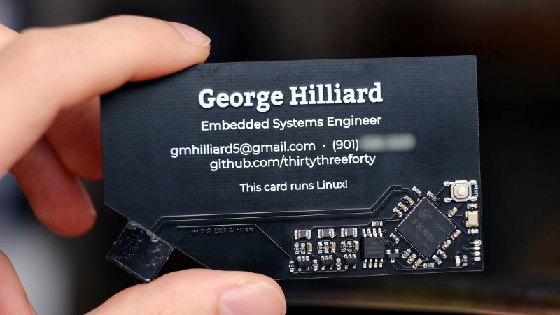
It takes a lot of work to get a functional PCB business card that’s thin, cheap, and robust enough to be practical. If you can even blink a few LEDs on the thing and still hand them out with …
tough matrix
@cerulean crest is it your project?
I remember seeing a year ago, but I re-read it now - and I am completely blown away by how much time and knowledge it took to do that. Kind of makes your own projects seem trivial in comparison 😦
cerulean crest
tough matrix
<@!461746819345416203> is it your project?
I remember seeing a year ago, but I ...
No, its a favorite of mine, and for a while I wanted to make my own version
elder peak
So... it's in the cards.
misty escarp
Does anyone see any issues with this? It's so simple I'm second guessing myself
supple pollen
Let's see, when the switch is actuated, the LED should come on, and A0 would see the forward drop of the LED plus the current drop through the 220Ω resistor. When the switch is not actuated, A0 would see the supply voltage.
However, if A0 is set as an output, hmm
misty escarp
Yeah I want to use A0 as input pullup
supple pollen
When it's high, and the switch is pressed, the LED would be lit brighter
You have an external pullup, so an on-chip pullup won't do much
If A0 is set as an output and grounded, not much will happen, there will be a small flow through the 4.7k resistor.
misty escarp
The switch state is meant to be used to wake an I2C screen
Added the LED so the user has something pretty to look at
Had a prof tell me they got a product funded because they added an LED and the VC person liked the blinking so now I consider them essential
misty escarp
Does a joint like this count as 90 degrees? Where each trace meets the pad as shown?
pearl tapir
Probably. I prefer to run the long trace to the one centered between the two pads but I probably tend to over engineer things.
pearl tapir
No. Just move it to the right a little so it goes only to the trace between the pads.
I can't help you there I use Mentor Pads Pcb.
misty escarp
Oh is that a "better" 90 degree joint?
misty escarp
pearl tapir
Probably. I prefer to run the long trace to the one centered between the two pa...
That's better than underengineering 😉 I'm always trying to learn the best practices so I appreciate the input
pearl tapir
What you have is one pad with three thermal sinks that will tend to twist a component as the solder cools. Solder has a self-aligning torque and if all the forces are equal, the component will center on the pads. The way you have it, the forces on pad on the left will not be even. Is it a big deal? No. Unless you want to build to 6 or 7 sigma defect level and then everything matters.
misty escarp
Three thermal sinks? The two power planes and the pad itself?
Something like this being better?
pearl tapir
Yes, imho.
supple pollen
I like big power planes and I cannot lie
quasi bloom
misty escarp
Does anyone see any issues with this? It's so simple I'm second guessing myself
that's a QTpy? powering w/ direct 3.3v to the 3V pin? i thought that was output-only
misty escarp
supple pollen
I like big power planes and I cannot lie
This brother from another mother can't deny
misty escarp
quasi bloom
that's a QTpy? powering w/ direct 3.3v to the 3V pin? i thought that was outpu...
I'm using the output as my pullup voltage. Power input is a wall jack via the USB port
quasi bloom
misty escarp
I'm using the output as my pullup voltage. Power input is a wall jack via the US...
ahh, gotcha. "not shown on schematic." should've realized it was something else. thanks!
misty escarp
Yeah good callout tho. This is just for my parents and they only know eagle as a danger to their small dogs, but I should make it more professional anyways
distant raven
@quasi bloom you can feed a regulated 3.3V into the 3V pin
I found out after some research that most voltage regulators have body diodes or can act as body diodes which is interesting
And unrelated, but totally PCB related: got my box of parts from Digi-Key 🥳
silk lark
well, they are a mosfet with a feedback
tough matrix
I never knew what is inside an LDO
tough matrix
any chance of repairing it using a thin wire?
misty escarp
well ruined is a strong word. I can run wires the device "wrong" and it still works
but I have to make it the last device in a chain since I ruined my in stemma qt connector traces
pearl tapir
tough matrix
I never knew what is inside an LDO
@tough matrix Often the data sheet will give a simplified schematic that shows the output configuration.
tough matrix
yeah, I understand how one can find it.. it is just that I never got to that page :)
But maybe it is about time
fast tundra
Finished up my reflow oven build. What a journey.
distant raven
Loving the Halloween feel
misty escarp
French press & keurig, always prepared
elder peak
Ooooh, the world needs a reflow oven with a speaker so you can hear the wails of flux leaving the solder paste like ghosts being converted into pure ectoplasmic energy.
elder peak
Also, my latest box of bits, which had been in an indeterminate state since last Friday, finally arrived, with a powerlifting bonus because the guy dropped my neighbor's package off on my doorstep as well. My neighbor's package was a 25lb weight.
distant raven
Geez
It makes no sense to order weights online when they can be easily purchased in a store
misty escarp
insert doc brown gif
elder peak
But, also, we're in shelter-in-place here so I guess folks want to avoid the stores.
misty escarp
we're shelter in place advisory but no one is doing it
it's gonna go real well I can tell
elder peak
I mean, I'm obeying it. I've got doc brown hair.
supple pollen
Me too!
misty escarp
I thought her cardigan was a lab coat for a minute
supple pollen
That would have been perfect!
 rigid dove
crossposting from #help-with-projects ,
https://www.actinius.com/icarus
https://www.nordicsemi.com/Software-and-tools/Development-Kits/nRF9160-DK/Download#infotabs
i understand one of these is sold by adafruit, so i know there will be some bias, but which one is better?
i want to end up using this chip in my own board, so maybe the DK is better as schematics are public, i dont need BT or any of the connectivity options provided by the official DK besides LTE
nRF9160 Feather Development Board by Actinius
misty escarp
I can't give a definitive answer but the featherwing form factor is really great, as it (obviously) fits feather boards
vapid grove
Guys, is it possible to use a regular oven as a reflow one?
unreal flax
You don't want to use a real kitchen oven because it will contaminate your food, but people have been able to convert toaster ovens into reflow ovens with replacement temperature controllers.
ember laurel
jig works 🙂
I need to make those pins 3mm instead of 2mm though
some carrying handles would also be nice, but this is really at the limits of my printer
ember laurel
now I just lack the hairnet and the mandarin skills
supple pollen
You could add some holes at the edges for carrying handles, print the handles separately, then snap/clip/screw the handles onto the jig. Actually, removable handles might be (ahem) handy.
ember laurel
yeah that could work
would be nice to have a sort of fixture to put them into the ultrasonic bath as well
this just for the prototypes though
perhaps I shouldn't bother too much 🙂
tough matrix
@vapid grove just talk to @fast tundra , she is doing exactly that right now
another option is using electric skillet/crepe maker
distant raven
Question for those who have PCB Mills
And not OtherMill by Bantom Tools
Does the milling bits that Bantom Tools sells for the OtherMill work with other desktop milling machines?
Also, has anyone used the SainSmart milling machines?
fast tundra
@vapid grove I used a hot plate for a long time before going the oven route, if you only do one board every now and then that's the most cost effective way.
pearl tapir
@distant raven I've used a T-Tech PCB mill and as far as I know, PCB end mills are .125" carbide. For outlining traces, T-Tech (and others) recommend an engraving bit. Generally, you want the widest bit that will get the trace spacing that you use.
If you need to hog out a wide area, use an end mill and use a side cutting end mill to cut the board out.
Most of the modern CNC routers like Carbide3d Nomad or even a Shapeoko will probably work for simple prototypes. If not, you probably need to get them etched.
distant raven
I’ve used a PCB mill before, I just wanted to know if the bits are compatible
pearl tapir
If they are .125", then yes. It's a standard size and the pictures on their web site look like .125". But it is possible they grind them to some odd size.
distant raven
I just don’t want to pay $2500 right out the gate
Also, how is the software that other mills use?
ember laurel
how are the cheapo mills from China?
pearl tapir
The T-Tech is locked down with a dongle. I don't recommend it. I think I'd build my own instead, probably a Three Design PrintNC which is ball screw driven. A small one of those would not be to expensive.
There is some open source PCB milling software like FlatCAM.
distant raven
Ugh, covid + holiday mail delays are the worst
Had some PCBs that should have arrived today apparently delayed
😓
supple pollen
Having the snowplow destroy your mailbox is pretty bad too.
distant raven
Ouch
tough matrix
My DHL delivery from Shenzhen is expected on Wed, Dec 23... fingers crossed
ember laurel
enough soldering for tonight
all those LQFP's and QFN packages take their time to hand solder
distant raven
Wowza
ember laurel
I really should get a fume extractor as well
I get the boards like they are on the left, minus the LQFP and QFN.
fortunately not hand soldering everything...
fast tundra
@ember laurel time to get a stencil & reflow oven/late
ember laurel
@fast tundra I ordered these with most components already in place
ember laurel
no way I'd do all 0603's on there
fast tundra
0603s aren't too bad, but anything lower than that I struggle with.
why are the smd parts only partially assembled?
fast tundra
ah gotcha
ember laurel
minus the whiskey
fast tundra
we do all of our smt stuff through MacroFab and then place surface mount stuff ourselves (since its more cost-effective at our scale)
ember laurel
I just do this for this batch of prototypes, need to have them out before xmas
takes time to setup an assembly line otherwise
fast tundra
yeah
we're about to start working on 150 jackboards (13 potentiometeres, 11 jacks, 2 pin headers) for our newest module.
that's gonna take some time. :3
ember laurel
I'm working with a factory in China to handle the series production
fast tundra
Ah cool. I try to keep as much as I can in NA.
ember laurel
why?
fast tundra
It's easier for us to communicate requirements and easier to maintain quality control.
ember laurel
I see.
I have had good work from this factory before
I come from the audio industry really
fast tundra
plus we don't have to deal with importing our own product. 😛
fast tundra
ah cool
Overseas is great if you have a good relationship with a factory, but it's really hard to build those relationships IME.
We have a good relationship with PCBWay for our panels (our panels are just PCBs), for example, and we have a good relationship with a specific manufacturer of audio cables for our patch cables.
ember laurel
Yes, sure. We have personal connections since many years now.
distant raven
I love the production process which is a main motivator for me doing as much as I can in the US
Plus doing it in the US is an interesting challenge that only a few companies have successfully done at large scale
I’m not very certain that my operation will ever be terribly large at least in pursuing my own designs. If I ever get decent equipment, I may contract manufacture boards for people
ember laurel
it's just incredibly difficult to compete with the Chinese prices
distant raven
Oh I know
ember laurel
if you have a product which will see scale, it's close to impossible to do that anywhere else :/
otherwise your competitors will just outprice you
distant raven
And that’s a risk worth taking I think
Hobbyist in general I think will opt for cheaper fabrication, but some people will pay for local manufactured equipment. And some companies will pay for that as well
It’s an uphill battle, but doable if you find a niche
ember laurel
it's just getting better that I think is hard
the good plants in China are just really great.
and they all work Monday-Saturday, 8am-9pm
it's nuts.
plus I get stuff shipped from Shenzen or Guangzhou to here, in 2 days.
distant raven
Yeah, I find the US’s biggest problems are:
- Unwilling work force (most don’t see the value in domestic manufacturing, so they generally don’t want to train for those careers)
- Government doesn’t want to invest in domestic companies trying to build up a domestic supply chain, rather they spend billions on overseas companies who have no intentions of following through
I’ve met so many goi g for engineering degrees who don’t actually want to be engineers, just PMs
And not to mention the vast number of people who go for business and finance where there is already a shortage of jobs for those careers
ember laurel
yeah I wonder what I will push my kids into 🙂
feels like half of the jobs here are in finance actually
distant raven
And then grade school and secondary schools not aligning curriculum to teach children to be inventive
I know so many people who “hate math” because they see so few people using it in the real world
ember laurel
heh...
distant raven
But i think most people hate math because they didn’t have a good teacher
distant raven
It’s a combination of teachers and parents being disconnected
ember laurel
but if kids get curiosity and manners from back home, they will go get it on their own
distant raven
Or having incoherent dreams and aspirations for their children
As a parent, I hope that I don’t do that to my children
ember laurel
Yeah, I try to do what I can for mine.
distant raven
I want them to see me get curious about a problem, design something, fail, and then try again from a different angle
ember laurel
We severely limited screentime for the kids, and they got SO much better.
distant raven
We only allow TV shows that encourage imagination and creativity
distant raven
iPads are for road trips because my kids get horribly car sick
ember laurel
out of boredom grows creativity
distant raven
Yup
ember laurel
Oh well yeah, I agree with that. Road trips is the exception
We usually do math quizzes on road trips, but at some point they get tired 🙂
distant raven
They use ABC mouse
ember laurel
7 year old already has a computer, but she really only uses it to do certain tasks for school
distant raven
Makes sense
ember laurel
I like that my son, 4, enjoys playing chess though
distant raven
We get my kids involved with cooking, cleaning, and whatnot
My son is a bit speech delayed so he’s just now getting to the super emotionally expressive stage
ember laurel
Our boy was also tons later than our daughter with speaking properly
distant raven
My daughter on the other hand is sharp as a tack
My son is too, but in different ways
distant raven
He has a very broad imagination whereas my daughter is more analytical
She loves puzzles
ember laurel
as analytical as you could be, with 4 🙂
distant raven
🙂
ember laurel
My daughter was never into puzzles, that's more for son.
distant raven
I’ve been working with my son on the concept that you can love everyone
Right now he only loves his mom, is cousin, and his dog
ember laurel
oh
distant raven
Daughter is 2
ember laurel
world of difference
distant raven
If I tell him that I love him, he says “no, I only love mom” haha
ember laurel
and dog
distant raven
Basically
tough matrix
don't get me started on the problems of math education in the US...
I have been involved in these discussions as parent and as teacher for the last 20 years... I can't take this anymore
@ember laurel how large a production run are you planning?
distant raven
tough matrix
don't get me started on the problems of math education in the US...
I have bee...
That’s right.. it’s terrible for sure. I appreciate the work you’ve done to try and fix things
tough matrix
we try to fix things locally - running enrichment math classes, math circles, etc - and working with gifted kids, this I had been doing for the last 35 years, ever since my own high school graduation
I know several professional mathematicians who were involved in global efforts - rewriting elementary school syllabi, promoting different teacher ed initiatives... with mixed results
distant raven
I think part of it is the everybody wants to be an artist syndrome
But people don’t realize you can make beautiful things with science and math and engineering
Not to say there isn’t value in art, people don’t realize that it’s engineering, math, and science that makes art possible
ember laurel
@tough matrix depends on how successful the product is. I estimate perhaps 600 units in year 1
3000 for year 3
But who knows, could be 100 units in total 🙂
I at least have minimum orders for about 1000 units over 3 years
tough matrix
wow
ember laurel
Mind you, the margin isn’t very high
tough matrix
as long as it is positive 🙂
ember laurel
I hope to break even 🙂
Depending how highly I value my time.
I also gotta pay some 50k USD to get a CB
tough matrix
cb?
ember laurel
CB cert.
tough matrix
oh
it is that expensive?
tough matrix
yeah, with medical I expect there is a lot of requirements
 reef flicker
Hey guys, I've got a quick question.. I found a (slightly cheaper) alternative to the sensor I was using
The only difference as far as I could tell is it's marked as "for harsh environments" rather than for water-resistance
Harsh environment: https://www.st.com/resource/en/datasheet/lps33w.pdf
Water-resistant: https://www.st.com/resource/en/datasheet/lps33hw.pdf
I'm not sure what the difference is between harsh environments and water resistance
reef flicker
The compare tab lists these two with different package dimensions too, even if their datasheet deffine strictly the same size
distant raven
Well, harsh weather is a bit more broad than just “water”
But both list weather stations as an application
reef flicker
According to the naming convention, the W stands for waterproof, with no such thing as "harsh environment"
Since I'm buying a bunch, it may be good to get the cheaper one but idk if I'm going to regret it
They certainly will have water and organic matter on them
distant raven
If water proof is a necessity, I wouldn’t cheap out
reef flicker
well i need the H anyways
 heavy jasper
Reading through a bunch of the documentation... it's not obvious to me that there's a clear answer. I suspect there may have been some modifications of ratings/product lines at ST somewhere in the middle of making these products.
In that they originally wanted to differentiate between the HW and W for different features, but then decided that they'll only make one. Or someone copy-pasted very badly in making datasheets. The "Harsh Environments" they're talking about are "long-term exposure to harsh environments such as water mixed with chlorine, bromine,
commercial washing detergent and fuels, solvents and chemicals" and the big example they give is for smartwatches that end up in chlorinated pools.
Some hardware guidelines here, originally written for the HW: https://www.st.com/resource/en/design_tip/dm00452854-lps33hw-digital-pressure-sensor-hardware-guidelines-for-system-integration-stmicroelectronics.pdf
But that now appear to be equally valid for the just-W variant, based on this section of the LPS33W:
vapid grove
reef flicker
According to the naming convention, the W stands for waterproof, with no such th...
That exact feeling, when you read MEMS as memes 😉
misty escarp
A SIC MEMS
reef flicker
@heavy jasper i read through the same documents, and have to agree that something weird is going on
Maybe they changed their minds? Idk
It looks like the internals are the same, and the only significant difference is the accuracy
heavy jasper
Oh, is the accuracy actually different?
reef flicker
Perhaps they decided to skip over some of the waterproof testings
That's what the H stands for. They're rated at different levels of accuracy
Or noise as they put it
But there is also a difference in how they describe the water resistance layer (waterproof vs harsh environments)
heavy jasper
It does look like the HW is slightly better absolute accuracy on pressure, though the noise specs appear to be the same.
reef flicker
heavy jasper
Looking at the datasheet, that appears to just be the internal filter/cal on vs off
(and the same thing is listed on both datasheets)
reef flicker
Yeah there's some odd stuff going on with that compare sheet
I'll just bite the bullet and take the 50¢ pricer model
Man these are pricy... I need 10 for the project and at 8$ a pop it stacks up fast
heavy jasper
You may be better served with a different module if you're not going to take advantage of the extra sealing features on this one.
In that here, it's not just IP67 as a module but intended to be an exposed port on an otherwise sealed module
reef flicker
Yes, I'm also buying o-rings
They'll slot right into the 3d printed part
(with a little luck and soldering madness)
heavy jasper
Also I think I linked the wrong hardware guidelines above, this one seems more useful: https://www.st.com/resource/en/application_note/dm00420205-lps33hw-digital-pressure-sensor-guidelines-for-system-integration-stmicroelectronics.pdf
reef flicker
The sensors are between the board and the part
Yeah I've read through that
Those dimensions of o-rings are not exactly easy to find at a reasonable price too
heavy jasper
Not massively surprising
Most folks who would do this for a product would get a custom O-ring specified for their design
(so, $$$$s of tooling then each part is ¢s)
reef flicker
I would've assumed that someone designing a part meant to be used with an o-ring would use a more readily available dimension
But eh, ordered a bunch of sizes from china and we'll see
vapid grove
Guys, I decided to make my own keeb
But I can’t find the difference between these jailhouse switches
CPG151101D06 and CPG151101D92
vapid grove
Also, which module adafruit uses in their nRF52840 boards?
unreal flax
Looks like it's one of the Raytac MDBT50 modules, from the schematic label. https://www.raytac.com/product/
 ember laurel
@reef flicker That looks awesome! How does it work? How do you sense the airflow in each opening?
I also take it that you are doing Bluetooth midi?
silk lark
is this a mouth organ?
reef flicker
@ember laurel there is an array of 10 air pressure sensors mounted on the side of the PCB we don't see (towards the 3d printed part). They can detect human breath and communicate MIDI with the computer
No plans for bluetooth midi at the moment to be honest. I've got enough on my plate 😁
ember laurel
Sounds awesome.
Bluetooth midi, and rechargeable battery - would be absolutely killer
I imagine getting each slot airtight to the other, with a nicely controlled airflow - will be the hardest part here
Also no idea if you can nicely “bend” notes like on a real harmonica
I even don’t know what actually happens when you do that.
@reef flicker still totally love your project though, and I hope to hear more about it!
silk lark
I'm working on an electronic ocarina, but didn't figure out which sensor to use yet -- either pressure or just a microphone
elder peak
I guess I can say that I'm blown away by these project ideas.
tough matrix
I was prompted by question from @distant raven and dug out my old project of making a manual pick-and-place machine
sure, it is questionable if manual PnP machines are of any use at all, but for those of us whose hands are not so steady, it could be useful
My plan was to make one using a construction set goBilda (used, in particualr, by many First Tech Challenge robotics teams), so as to minimize the amount of required laser cutting/3d printing
Here is my draft - what do you think? would it be useful?
https://a360.co/37zEJr3
Share 2D and 3D design files and project files with anyone.
reef flicker
silk lark
I'm working on an electronic ocarina, but didn't figure out which sensor to use ...
from my testing, pressure sensors are easier to work with
But since in your case you don't need to draw breath as well as a blow, then I guess either could work
silk lark
yeah, I need to just do some experiments
reef flicker
Microphone I wasn't able to get the precision I really wanted
misty escarp
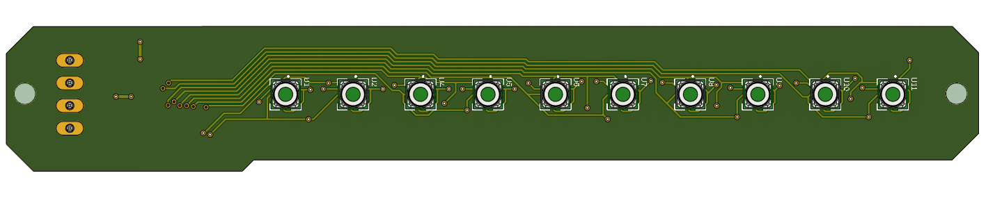
So is it each sensor corresponds to a note? and then the note gets played if the sensor detects over a threshold?
reef flicker
Since you rely on the noise of air moving, it's not really as precise, and there's many other factors to consider. What if you're playing with a band? Or in a noisy environment? The mic will tend to pick that up. Worst case, it will start "playing" by itself while you're on silences because of a loud guitar solo
reef flicker
misty escarp
So is it each sensor corresponds to a note? and then the note gets played if the...
For the harmonica? Yeah, this render shows the "inside" part of the PCB, the one that mates into the 3D printed part https://ferdz.needs-to-s.top/8Wz2QgL.png
 misty escarp
I'm biased because I think they're awesome, but I think you should consider a stemma qt port for your I2C signals

 misty escarp
yup!
reef flicker
Yeah that would be much nicer than headers pins 😛
misty escarp
they are a little harder to solder than the pins you have but there are out of the box connectors for them that adafruit sells
reef flicker
A bit late for this version since it's in the mail but next time
misty escarp
how long of a cable are you using btw?
reef flicker
For connecting it to the mcu? As small as I got... Think about 20cm?
How would I setup that connector to work on an off the shelf mcu board?
misty escarp
Ah yeah they make short versions of the cable that have a stemma on one end and jumpers on the other but it's pretty short
which MCU?
reef flicker
I'm getting pretty cramped on space, idk if I'll be able to fit the MCU directly on the sensor strip board, but I'm thinking I can mount it on top of the other board and hold it on with header pins
Atmega32u4
misty escarp
oh cool beans
reef flicker
And I'm scared of designing my own MCU board, even though looking at it it appears to be quite simple
misty escarp
The 32u4 shouldn't be too bad
reef flicker
https://learn.adafruit.com/introducting-itsy-bitsy-32u4 just from looking at it, it doesn't look like it's very difficult... Maybe I could grab the files and modify it to only have the pins I need

Adafruit Learning System
What's smaller than a Feather but larger than a Trinket? It's an ItsyBitsy!
reef flicker
Through the USB no?
misty escarp
ah I think we mean different things heh
reef flicker
Yeah, the pins on the outside
misty escarp
Ah yeah, I meant on the MCU when you make your own
reef flicker
Completely (kinda) unrelated note. I'm looking for cheaper providers for my sensors. Found a listing for it on alibaba, and after contacting the seller they're asking for a (much) cheaper option than I could get here
Is it too good to be true?
tough matrix
regarding programming:
before you can use USB, you need to put a bootloader on the chip
for AVR chips such as 32u4, it is commonly done using so-called ICSP header
reef flicker
Hmm.. I'll have to do some research on that
For this version it's pretty out of scope, but maybe eventually it will be useful
tough matrix
it is not that hard
misty escarp
I have to decide if I'm gonna buy a real programmer, gonna try using an arduino first though
It's among the several tools missing from my toolkit
misty escarp
yeah, I have seen a guide for adding CP with an arduino so gonna go with that first
reef flicker
Are programmers just USB dongles of some kind that hook into those pins?
tough matrix
basically
misty escarp
$100+ dongles T.T
tough matrix
e.g. here is one possible porgrammer for AVR: https://learn.sparkfun.com/tutorials/pocket-avr-programmer-hookup-guide
nah, it is more like $20
for m0/m4, you can use this https://www.adafruit.com/product/3571

Doing some serious development on any ARM-based platform, and tired of 'printf' plus an LED to debug? A proper JTAG/SWD HW debugger can make debugging more of a pleasure and less of ...
misty escarp
Ah I was looking at the more expensive model I guess
tough matrix
if you do not need commercial - i.e., not selling your product - then EDU version is fine
misty escarp
oof that price increase
tough matrix
commercial SEGGER costs like $400
reef flicker
So running back to the alibaba supplier, anyone has experience ordering parts from there?
misty escarp
I've only heard it's hit or miss
tough matrix
what sensors are you looking for?
reef flicker
LPS33HW
For 1 harmonica (10 sensors) they turn out to be almost 100 CAD, so that's a bit steep
Trying to save a little bit on them, especially since I'll probably destroy a few
tough matrix
mouser gives price of US$56
for 10
I have my doubts about ordering them on AliBaba. Unlike connectors or enclosure boxes, this is something must be produced by STM, not by a random manufacturer
tough matrix
maybe. I don't know. What price are they offering?
reef flicker
2.85 USD/pc for 20pcs
tough matrix
half the price of mouser
reef flicker
Which is significantly lower than anything else I've seen