#help-with-hw-design
1 messages · Page 38 of 1
 ripe dawn
 urban lark
I'm pretty sure they have nano-LEDs, just hard to find once you put them down
ripe dawn
I hand soldered wires to some 1010s (much profanity was involved) and then promptly ripped two of them off while attempting to position it to record a video. Have not yet built up the patience for another attempt 😅

I want to buy/make some high density flex strips with them at some point, similar to what you can buy with the 2020s. If anyone knows of any lmk 👀

 wheat notch
ripe dawn
I hand soldered wires to some 1010s (much profanity was involved) and then promp...
wheat notch
ripe dawn
I hand soldered wires to some 1010s (much profanity was involved) and then promp...
1010 LEDs, or 1010 addressable RGB LEDs? Doubt I could manage even two wires without a lot of failed attempts.
ripe dawn
wheat notch
1010 LEDs, or 1010 addressable RGB LEDs? Doubt I could manage even two wires w...
Addressable, WS2812Bs
wheat notch
 ripe dawn
very small pads
 wheat notch
smallest ones I've got on strips are a bit smaller than 2020s
ripe dawn
Any tips/tricks for soldering wires to the contacts on these strips? I always seem to struggle with it. I also worry that my (repeated) attempts may destroy the nearest LED (or worse, it still works but greatly reduces its lifespan).

And yes, in this pic the adhesive is still covering the contacts. I removed it from the other end, but I'm not going to show you just how badly I butchered that end 🙈
 drowsy drift
ripe dawn
Any tips/tricks for soldering wires to the contacts on these strips? I always se...
drowsy drift
ripe dawn
Any tips/tricks for soldering wires to the contacts on these strips? I always se...
Normally one solders on the other side
ripe dawn
drowsy drift
Normally one solders on the other side
There is no other side

 prime raptor
ripe dawn
And yes, in this pic the adhesive is still covering the contacts. I removed it f...
prime raptor
ripe dawn
And yes, in this pic the adhesive is still covering the contacts. I removed it f...
Clearly you'll have to make sure the solder pads are clean for solder to stick. You'll need something that is a solvent for that adhesive, maybe acetone. I'd then apply some flux paste and pre-tin the contacts. Then you should have little problem soldering on the wires.
drowsy drift
ripe dawn
There is no other side
Oh those are the dense kind. What you’re doing is the right way. You can use isopropyl alcohol and an xacto knife to get the adhesive off
And what @prime raptor said 🙂
prime raptor
I'm not sure any kind of alcohol will remove that adhesive. Acetone or maybe turps might.
Nail polish remover for those who don't have "acetone" in the house. Same thing. ...although I'm old-fashioned, maybe modern nail polish remove doesn't use acetone, dunno. I don't do my nails very often 😬
drowsy drift
For some of those adhesives, I’ve found that IPA does a least make it a bit rubbery and easier to scrap off with a knife
ripe dawn
I did clean the other end, and even got two of the three wires attached, but in the process of trying to get the third to stick things went downhill and follow-up attempts just made things worse, destroying the wire insulation, and have me questioning the integrity of this part of the strip, which is my I was hoping for some tips for a fresh attempt. Sounds like I need to just go through the process again and hope for the best. (Warning, it's gruesome)
 ripe dawn
prime raptor
I'm not sure any kind of alcohol will remove that adhesive. Acetone or maybe tur...
ripe dawn
prime raptor
I'm not sure any kind of alcohol will remove that adhesive. Acetone or maybe tur...
Won't acetone melt whatever the plastic backing the flex is made of?
prime raptor
ripe dawn
Won't acetone melt whatever the plastic backing the flex is made of?
If you soaked it in acetone yes, but if you clean the contacts with a Q tip wetted with acetone you’ll be fine
The backing may be something other than plastic but I’m not sure. But acetone evaporates quickly so a small amount on the contacts will do no harm
prime raptor
ripe dawn
I did clean the other end, and even got two of the three wires attached, but in ...
If you have the contacts on the LED strip lightly tinned, and you have the ends of the wires clean and tinned, you should be able to hold a wire to the contact and just apply a small amount of head and a bit more solder and it should attach easily. Make sure during this that you have both sides held (physically) together so that you don't have to juggle around and take more time, a single solder joint should be done in about a second. And that you're using a suitable soldering iron, i.e., one with a small enough tip. Flux really helps, generally the flux inside "rosin-core solder" is enough. I'd also be soldering the wires on to the contacts 180° from the angle you used, basically the wires would hang off the end of the strip rather than doubling back on it.
I seem some of that orange adhesive on the contact that isn't obscured by wires. If there's adhesive on the contact there's little likelihood of heat transfer and success.
ripe dawn
Hmm yeah I did tin the pads and the wires ahead of time, but something still went awry. I would normally solder 180º as well but this is being installed in a "borderless" location where there won't be space for the wires to bend/poke out.
urban lark
My "connectors" arrived... encased in aluminium and covered in rubber, but no pcb traces go inside the port under the board, and the pcb only extends a bit for mechanical advantage, seems a simple enough connector


 ripe dawn
What is the goal/usecase? You're not going to be able to use it simultaneously as a card reader and other type of USB device. If you just want a card reader…what's wrong with the existing ones you can buy?
urban lark
the game is to simultaneously use both, the USB-A and the micro-sd. That's what the devices advertise. This one just happens to also have a usb-c on the other end (for phones with no A support). The other one I bought that is just USB-A and micro-SD won't arrive for weeks
Eventual use would be a very small MCU project, that has the sd for logging + assets, and usb-a for power/flashing/host stuff.
ripe dawn
Hmm yeah, I feel like the market for a USB/TF socket combo that isn't just an in-built reader is so small/nonexistant that it's going to be hard to find an existing (or at least readily available) component that does that. I wonder if you could instead get a minimal socket and sandwich that on the back of a (thinner) PCB with the USB-A contacts so that it fits just right in the port 🤔


Or if the socket itself is narrow enough that you could shove it into the metal housing for a USB-A port 🤔
urban lark
Yeah small market for sure, but I like a challenge - keeps the brain active ☺️
I do like the idea of making one, and there's even a connectors place up the road, but the cost and quantities locally would be terrifying.
I do like the DIY talk, especially the sandwich 🥪 although I can imagine fragility. I wonder how crazy it would be to attempt to wrap metal around objects to make connectors.
ripe dawn
You've certainly nerd sniped me into such a project even though I don't need it 😅 I've been wanting to make something like this for fun https://youtu.be/pgvJ-Z2olTg?t=232 and might as well add a micro SD card slot while I'm at it
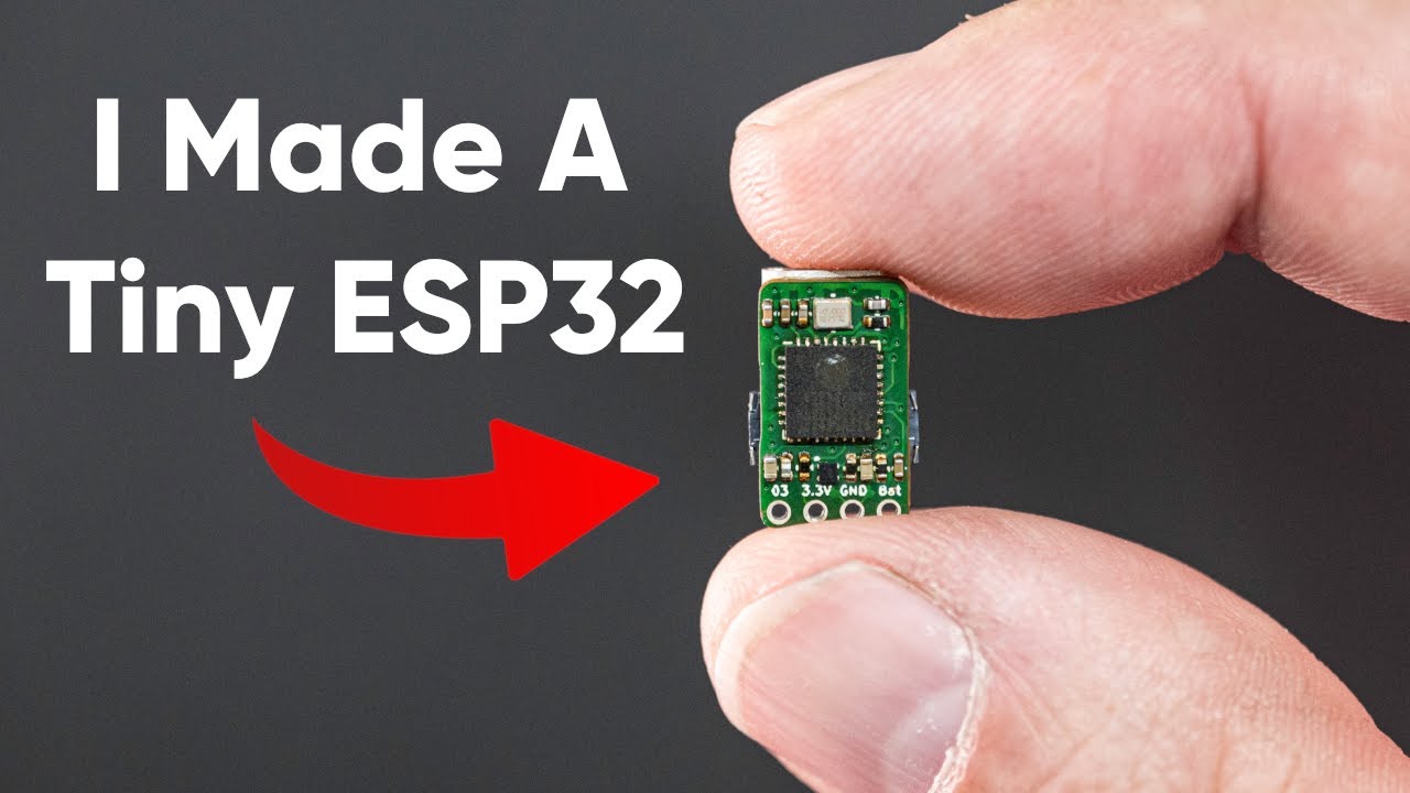
check out my stores where i sell some of my creations https://www.tindie.com/stores/smartbee/
EU/UK buy here https://www.lectronz.com/stores/smartbeedesigns
Affiliated links for the things in this video
Mini Hot Plate - https://amzn.to/3RnFTga
iFixit Tweezers - https://amzn.to/3Rr1ILZ
Low temp solder paste - https://amzn.to/3uBbH8e
high temp so...
 tulip swift
ripe dawn
You've certainly nerd sniped me into such a project even though I don't need it ...
tulip swift
ripe dawn
You've certainly nerd sniped me into such a project even though I don't need it ...
Very cool but I question why you used some of your limited holes for things like BAT? With only one GPIO available, typically an ESP would be run with just the board alone if you were doing a lot of the work over WiFi where BAT might be useful for deploying a board somewhere not near easy plug in power and so having to run off battery and send/receive data via WiFi. Those four pin locations might be better suited for a "Stemma" type I2C setup instead where you could daisy chain off sensor and such. Also another way to gain a bit of space is get rid of the USB connector and put in small pads for the USB connections and then for programming you would use a small jig with pogo pins to connect the pads to a USB connector to hook to your computer. Now with the newfound space you could keep BAT, 3.3V, and GND and increase your GPIO from 1 to 3 or 4.
Or maybe this was a long way of putting it now that I thougt about it more while writing this, you should decide is the board meant to be powered off a USB port or is it meant to be powered off a battery (or other two wires external source)? Then get rid of the opposite part you don't need (i.e. if powered by BAT get rid of the USB connector and if powered off USB then get rid of the BAT and 3.3 and add more GPIO).
ripe dawn
tulip swift
Very cool but I question why you used some of your limited holes for things like...
First off, to clarify, this isn't my design, just a video I saw a while back. 😅 I would probably make a few modifications, definitely including more GPIOs. I think I'd still want to include a battery charging circuit just in case I want to use it that way, but would probably make them very tiny pads as that would likely be a rare use case for me.
tulip swift
ripe dawn
First off, to clarify, this isn't my design, just a video I saw a while back. 😅...
Oh sorry I read your post as "I've been wanting to make something like this for fun [and here it is]". I think if I wanted a board to be that small, basically as absolutely small as possible, then I would leave the battery charger out and just swap out batteries as needed, especially if my idea of getting rid of the USB connector was in use, it would be harder to plug it in to charge.
ripe dawn
Is there a good strategy for connecting bridging adjacent perfboard pins that are on opposite side of the board? As a (somewhat contrived, but sometimes desired) example this represents a row of male headers next to a row of female headers on the other side. If this was something like a DIP IC you could probably get away with soldering to the "top side" of the legs if necessary, but there's not a gap around the plastic here to do that. I've tried snaking some little "U" wires in there, but it gets rather tedious and tend to pop out while inserting the headers.

 timber wyvern
ripe dawn
Is there a good strategy for connecting bridging adjacent perfboard pins that ar...
timber wyvern
ripe dawn
Is there a good strategy for connecting bridging adjacent perfboard pins that ar...
Is there a reason you can't use 'stacking' female headers instead, which are basically female headers with extra-long pins and not have to have the two separate rows of pins if they need to be electrically connected already?
Something like these: https://www.adafruit.com/product/3366
ripe dawn
In this particular case it was connecting two different boards of different widths (e.g. 0.6" to 0.8")
timber wyvern
Could still benefit from the approach. Align one side, then you have a 0.2" gap on the other side which gives a whole extra row to run the s-curve wires through on the other side to connect socket-to-pin more cleanly perhaps.
Because otherwise, yeah, there's no good way to connect stuff on perf-board that's on opposite sides but only 0.1" apart.
But making one side 0" apart with stacking pins and 0.2" on the other side could be a lot easier to assemble even if still a little tedious.
ripe dawn
Hmm true. In my case I needed to connect most but not all of them, but I could probably rip out individual stacked headers as needed
 hasty solar
is there a common prefab board or IC that handles switching a higher-voltage component with a lower voltage using a MOSFET or BJT? basically a circuit like this?

(with the logic-level voltage off to the left behind R1)
i can just wire this onto a board if i need to but it seems like it'd be a very common pattern
 knotty tiger
there’s solid state relays, but they tend to be larger and more expensive than what you’re probably looking for
hasty solar
yeah, and this is meant to work with a PWM signal so I don't think relays will switch fast enough
knotty tiger
they’re usually implemented as optically isolated triacs (AC) or phototransistors (DC)
there’s integrated low-side driver ICs, but most of the ones i found quickly need external flyback diodes to drive inductive loads
hasty solar
bleh, yeah if it's not self contained then I'd probably just go for the individual analog components
knotty tiger
H-bridge motor drivers often have integrated flyback diodes, but they need more logic to drive
hasty solar
right yeah, and probably overkill for just PWM with no other needed logic
alright, I'll probably just make a tiny board with the two little circuits I need to put next to the pumps I'm driving
knotty tiger
there might be low-side switches with integrated flyback diodes, i’m just not able to quickly find them in a search
hasty solar
looking into it there are logic level FETs with integrated diodes but I think you'd still need one for the load itself
 latent jungle
hasty solar
is there a common prefab board or IC that handles switching a higher-voltage com...
latent jungle
hasty solar
is there a common prefab board or IC that handles switching a higher-voltage com...
Sparky the Blue Smoke Monster shows up whenever the magic smoke is let out of an electronic component. And his very favorite is whenever folks first start with electronics and robotics: ...
hasty solar
solid, thanks!
hasty solar
just checked the pump i'll be driving with this and it notes that it draws 6A, but the adafruit board's mosfet is only rated for 3.6A. looking at this IC instead: https://www.digikey.com/en/products/detail/infineon-technologies/BTS3125EJXUMA1/7323978
will this do the job?

DigiKey Electronics
Order today, ships today. BTS3125EJXUMA1 – Power Switch/Driver 1:1 N-Channel 10A PG-TDSO-8-31 from Infineon Technologies. Pricing and Availability on millions of electronic components from Digi-Key Electronics.
per the datasheet it has an integrated diode
knotty tiger
looks to be the body diode of the MOSFET, which might have limited capabilities, depending on how inductive your load is
ripe dawn
What voltage? And DC? These can be driven by as little as 2V
 tulip swift
ripe dawn
What voltage? And DC? These can be driven by as little as 2V
tulip swift
ripe dawn
What voltage? And DC? These can be driven by as little as 2V
Note that the 2V is only when the datasheet gaurantees these will START to conduct. The dirty details are in the graphs and 6A at 2V may not be possible. But drive it at 3+ V and should be able to do it reliably and of course the higher you can drive the gate the better.

 pastel night
hasty solar
just checked the pump i'll be driving with this and it notes that it draws 6A, b...
pastel night
hasty solar
just checked the pump i'll be driving with this and it notes that it draws 6A, b...
there are high and low side driver in similar families that will handle just about any current / voltage you need. you get a lot more functionality / reliablity than a mosfet diode and some extra cost. There are several catagories they are labeled with (depending on intended use). The usual fall into the PMIC Load Drivers.
e.g. https://www.digikey.com/en/products/detail/infineon-technologies/BTT3050EJXUMA1/16580772 if you wanted to PWM the fan, wanted it to handle OV, UV, ESD, Short, OC, thermal. 4 amp continous, 10 amp peak.
DigiKey Electronics
Order today, ships today. BTT3050EJXUMA1 – Power Switch/Driver 1:1 N-Channel 4A PG-TDSO-8-31 from Infineon Technologies. Pricing and Availability on millions of electronic components from Digi-Key Electronics.
hasty solar
what would motivate me to pick this IC over the one i've linked?
pastel night
both are good... frankly i would go with less. NSE11409-QSTBR would be another option. Probably still over kill. SOT-223 and SO-8 types are fairly common. Lower current rated devices will save pennies.
 worthy pebble
Im looking on how to use 12v 4pin pc fans with microcontroller
ripe dawn
You'll want to confirm the exact pinout for your specific model, but generally one is power, one is ground, one you provide a PWM signal to control the speed, and one that signals back what the actual/current speed is
https://allpinouts.org/pinouts/connectors/motherboards/motherboard-cpu-4-pin-fan/
timber wyvern
It doesn't vary from model to model, if it's a PC fan rated to plug into the 4-pin PWM connector on motherboards it's this spec:
https://www.intel.com/content/dam/support/us/en/documents/intel-nuc/intel-4wire-pwm-fans-specs.pdf
The PWM and Tach pins are both 5V logic, so with most microcontrollers you'll need a logic-level translator. Tachometer is fan->MCU, PWM is MCU->fan so both can be done with unidirectional logic-level translators.
12V is needed on the VCC which can be complex and if you get the pins/connector wrong you can fry the MCU so getting a 5V fan model if you can is helpful.
worthy pebble
I wanna use what i have right now. But from what you guys wrote i guess that i can controll pwm using adafruit emc2101 (or smth like that) and add 12v power input to fan using separated circuit
Fan im gonna use is regular pc fan so pinout is easy to find
 fervent lance
I was looking to an ethernet for both power and data to an esp32, so I was looking to a TPS2376D which handles the power, and to a LAN8720 which partially handles the data being a PHY thing. Now, for the sake of semplicity, does not exist one single package that deals with both ?
 unique patio
fervent lance
I was looking to an ethernet for both power and data to an esp32, so I was look...
unique patio
fervent lance
I was looking to an ethernet for both power and data to an esp32, so I was look...
I think you are unlikely to find a single chip that does both, because the process requirements for power vs the computation/signal stuff are different, and also the power stuff may cause interference to the signals. But you are likely to find a board/module with both. We sell splitters that take a POE connection and tap off power at various voltages
unique patio
fervent lance
I was looking to an ethernet for both power and data to an esp32, so I was look...
https://shop.m5stack.com/products/esp32-ethernet-unit-with-poe comes with some AT-style interface, but maybe you could load other firmware
m5stack-store
PoESP32 Unit is an Ethernet ESP32 lan Unit supports ESP32 PoE. This module adopts ESP32 as built-in MAC, and IP101G as physical layer transceiver. Default firmware with ESP-AT, supports TCP,MQTT, HTTP protocols. It can connect to server with simple AT commands through serial port, achieving data transmission and remote control functions.


Interesting review/comment: https://media.reviews.co.uk/product-snippet/26678055

https://www.microchip.com/en-us/development-tool/EV46B51A ridiculous price
fervent lance
unique patio
https://shop.m5stack.com/products/esp32-ethernet-unit-with-poe comes with som...
I was taking as a reference this
https://www.olimex.com/Products/IoT/ESP32/ESP32-POE/open-source-hardware
But it does not support data, but this thing should add it https://www.waveshare.com/w/upload/1/1a/LAN8720A.pdf
but it seems that both the Poe ic and the PHy thing, both require 8 pin out of a rj45, and I can't use an old 4 pin thing
(although GPT says that's possible, but from a keyword search through the docs, I see no mentions about it, so I guess it's hallucinating)
unique patio
fervent lance
I was taking as a reference this
https://www.olimex.com/Products/IoT/ESP32/ESP32...
https://deluisio.com/networking/2024/08/31/power-over-ethernet-poe-pinouts-guide-with-cable-colors/ 4-pin POE is possible. 8-pin lets you have higher curent
unique patio
I just searched for 4-pin ethernet poe and came up with that. In general I ignore AI summaries and don't try to ask AI questions like this.
 charred merlin
worthy pebble
Im looking on how to use 12v 4pin pc fans with microcontroller
charred merlin
worthy pebble
Im looking on how to use 12v 4pin pc fans with microcontroller
DroneBot Workshop just posted this today if you haven't figured it out 🙂 (haven't watched and no affiliation, but he's always got great videos)
https://www.youtube.com/watch?v=A0j7BsLcnxg

Today, we’ll build a temperature-controlled PWM fan controller with an OLED display and an ESP32. Along the way, we’ll learn all about 4-pin PWM fans and how to use them.
Article with code: https://dronebotworkshop.com/esp32-pwm-fan
More articles and tutorials: https://dronebotworkshop.com
Join the conversation on the forum: https://forum....
 woven creek
is there any chance anyone has a clue as to what this missing component on my AksIM-2 was? I accidentally knocked it off by using too long of a screw when mounting another part of my assembly, and I lost it while trying to solder it back on. It looked the same as the other black SMD component I circled (the lower one). It's shaped like a capacitor but I know SMD inductors can look like that too. Even if it is an inductor I doubt I could match the value, but this is such an expensive part I wanted to at least make the attempt to fix it before I give up and buy another one. It's an absolute rotary magnetic position sensor if that helps.

 heavy jasper
Found another photo online that looks like the same board:

It seems like it is a ferrite bead / SMT inductor (more likely ferrite bead by my eye and guess). It may just be part of a power filter, in which case, depending on your application and amount of ambient electrical noise… you might be able to just bridge over it with wire and it might work well enough.
woven creek
thanks for the response!
that's kind of what i thought! the whole reason i'm using this encoder is because it's supposed to have lower noise than a lot of cheaper ones. I do have a noise sample that I took before I broke it though, so I could just try bridging it and take another noise sample to compare.
But it also sounds like the exact value of the component maybe isn't necessarily super critical? especially if it's just a power filter. The sensor chip is on the other side of the board, pretty much right below that component, by the way, so that'd make sense. I might just put a random bead on there and see what happens.
heavy jasper
Non-correct ferrite beads can make the noise worse, depending on resonant frequencies of the load draw and interaction with the decoupling capacitors, or just from having so much resistance that the larger current spikes of the downstream device cause a larger IR drop in the bead.
But probably the sensor is fairly low current, so it’s probably not a huge deal.
 woven grail
Not sure this is the right place but I'll ask anyways... I bought some UV 365nm LEDs which I want to control using a WS2811 chip. My supply voltage for everything is 5V but the LEDs state forward voltage should be DC3.2-3.6V, the bit that throws me is the forwards current is stated at 600mA. Sticking this into a resistor calculator says I need a 2.5ohm resistor? Does this seem correct? 600mA seems very high for a single small LED.
These were the LEDs I bought (3W, 365nm), they are tiny:
https://www.aliexpress.com/item/1005006023110795.html?spm=a2g0o.order_list.order_list_main.23.16b318029jRQgn#nav-specification
I am using these boards to control them:
https://www.aliexpress.com/item/32821263233.html
and passing through the 5V from the board
 supple pollen
I don't think a WS2811 will sink that much current. Do you really want to run these LEDs at full power? Shortwave UV like that can be dangerous.
Normally high power LEDs like this are run with transistors.
woven grail
If I stick a larger resistor between the power source and the LED I would reduce the maximum current?
I'm going to try and see if it still lights up with a much larger resistor
supple pollen
Yes, it will reduce the current, the LED should still light, just produce less output
woven grail
I guess my question here is if there is a risk of blowing the LED by running 5V through it at any point, I guess pretty much no risk since the max current allowed is so high?
unique patio
woven grail
Not sure this is the right place but I'll ask anyways... I bought some UV 365nm ...
Be careful with these. Not good for your eyes at long exposures. Do some websearching re 365nm safety
prime raptor
unique patio
Be careful with these. Not good for your eyes at long exposures. Do some websear...
If you've got a 3 Watt UV LED you won't be able to see much light coming out of it since most (but not all) of its output will be in the UV range. Even if you're running it at 30%, 1 Watt of UV light can be quite dangerous if it's shining right into your eyes. I would not look at these directly when they're on at all (not even to see if they're turned on), consider shining them on a white paper or some other kind of surface rather than looking at them directly. You really don't want the permanent tinnitus version of vision.
Here's a table I found:
Power (Watts or mW)   UV Type   Risk (if direct eye exposure)
~0.1 mW               UV-A      Possible cumulative damage over time
1–5 mW                UV-A      Harmful if stared at for seconds
>5 mW                 UV-A/B    Risk of acute damage (especially B and C)
Any UV-C (>0.1 mW)    UV-C      Immediate corneal damage possible
Note: those are milliWatt (1/1000th Watt) ratings. 395nm is in the UV-A band, so 1 Watt of UV-A is 1000x more harmful than the table "if stared at for a few seconds"
unique patio
@woven grail 👆
prime raptor
What is sometimes rather frustrating is that looking at the product page on AliExpress, there's nowhere any mention of the dangers of these LEDs. Not one peep.
No, these are 3W LEDs, so 33% is 1 Watt. That same page also sells 5W versions 😱
woven grail
I'm curious here, how can such a small LED be 3w? and why are they so cheap if so powerful? I'm kind of hesistant to plug them in at all.
prime raptor
woven grail
I'm curious here, how can such a small LED be 3w? and why are they so cheap if s...
Over the past 20 years LEDs have come a longggg way. I've got a really nice and tiny NiteCore flashlight/torch. It has a turbo mode that is too bright to look at, by far. They make a handheld that is bright enough to light up a sports stadium.
woven grail
Like these LEDs from pihut are 20mA but are larger than those supposed 3W ones I have:
https://thepihut.com/products/uv-uva-400nm-purple-led-5mm-clear-lens-10-pack

The Pi Hut
Need some really bright LEDs? We are big fans of these 5mm clear UV / Purple LEDs. These emit UV 'blacklight' in the UVA spectrum so they are great for projects with fluorescent materials referred to as UV/blacklight-reactive or 'glow-in-the dark'. They are bright (350mcd) and have about a 20-degree LED beam. They go easily into a breadboard and...
prime raptor
20,000 lumens
https://flashlight.nitecore.com/Product/tm20k
The NITECORE TM20K is an Ultra High Performance Tactical Searchlight to emit a max output of 20,000 lumens, equipped with an innovative operating system for switching user modes. It is one-hand operable and equipped with the built-in 21700 Li-ion batteries and a USB-C charging port. With the CNC machined unibody design, the TM20K is solid and du...
pastel night
i have a blue LED from the 1980's that is so dim you can barely see it in daylight... yes, LEDs have come a very long way.
ionizing radiation (uvc) needs to be handled very careful, but also air (and just about everything else) absorbs it. use proper ppe and you should be fine (primary risk is to eyes) in most cases.
prime raptor
pastel night
ionizing radiation (uvc) needs to be handled very careful, but also air (and jus...
Yes, LEDs have come a long way. I remember when lots of people didn't think blue or white LEDs were even possible, until they were.
But what is the proper PPE for the eyes when dealing with a 3W UV LED? I think it's extremely important (and only barely within the guidelines of this server) to provide very careful advice on handling what are — to anyone and anything's eyes while the LED is operating, even at 5% of its rated power — quite a significant hazard.
So unless you are entirely comfortable with the responsibility of providing such advice I would be very careful. I am trying to be. E.g., these LEDs are not UVC. 365nm is UVA. UVC would be significantly more dangerous.
pastel night
which is why i was very general about my statements. The details of what is recommended are out there on the web... (i've done formal safety assements, but my resourses are old and out of scope here).
prime raptor
pastel night
which is why i was very general about my statements. The details of what is reco...
I guess I was reacting to: "use proper ppe and you should be fine"
timber wyvern
Yeah, "proper PPE" for UV LEDs in that power range, even UVA, is broadly "a brick wall" or else equally expensive UV-opaque glasses.
prime raptor
timber wyvern
Yeah, "proper PPE" for UV LEDs in that power range, even UVA, is broadly "a bric...
And I'd hesitate to rely on any information on the Web for safety, except that from a truly reputable source. That you can just buy these LEDs from AliExpress without so much as a warning on the product page is a bit shocking. It's a bit like selling a weapon.
They look like innocent little LEDs, and the scary thing is that anyone plugging one in won't even see the UV light that's doing the damage. My understanding is that they'll emit a bit of light in the visible-violet spectrum, but most of their power is invisible. So someone turning one on might actually look at it to see if it's working. At 3W even a reflection is dangerous to one's eyes.
I'm sure some people might think my reaction is over-the-top, but if you read up on what a 3W UVA LED can do, you'd understand. And as a specific warning to @woven grail, no, I wouldn't recommend plugging them in at all. These are not remotely in the realm of consumer/hobbyist-level LEDs.
 worn iris
would someone mind doing a quick review?
basic gist is a pi pico on a 3-ish inch disc then some pins for a 1.44in display, haven't really done any pcbs aside from basic breadboard pin to connector.
i'm sorry about text being upside down but i can't be bothered for a one-time so have a model instead 
lmk if you need see any section in detail or have any tips for me


 worldly schooner
worn iris
would someone mind doing a quick review?
basic gist is a pi pico on a 3-ish inch...
worldly schooner
worn iris
would someone mind doing a quick review?
basic gist is a pi pico on a 3-ish inch...
- GP12 is not connected.
- I don’t see any of the decoupling capacitors (c17-c25) in your layout. Are they there?
- c111 does nothing in this schematic. I believe one end of that capacitor is supposed to connect to ground.
- I’m not familiar with that usb connector, but it doesn’t look like a standard connector. Is that something you picked out for a very specific purpose, or did you mean to pick a usb-c?
Other less important details:
5) edge pad spacing is super inconsistent. Does it have to be arranged in an arc, or would a straight line be more practical for header pins?
6) lots of space on the front side, add a ground fill if not needed for anything else.
7) do you need (or want) mounting holes?
worn iris
worldly schooner
1) GP12 is not connected.
2) I don’t see any of the decoupling capacitors (c17-c...
Thanks for the pointers, that port is 10 pin usb c but only wired for USB 2
Tbh I got no idea about those caps, they are in the schematic but they refuse to appear for component layouts so there may be no footprint model in the program for those caps
I don't need to do it in a arc but then they end up all bunched together and becomes slightly more annoying to route so I opted to just separate them, before i had em laid out in bunches of like 4-8 like this
I probably won't need mount holes I'll just have a clip/support printed out or a classic tape it til it stays

In a out a hour I'll go see about swapping the caps with a equivalent and see if those show up in the pcb layout
Also I'll go and fix my text and edge spcing 
worldly schooner
worn iris
Thanks for the pointers, that port is 10 pin usb c but only wired for USB 2
Tbh...
Capacitors are generic components that require their footprints to be manually defined before they appear in layout. Whether you use 0805 or 0201 is completely up to you.
As for the pads, I would personally keep them in “bunches”, but align them to loosely follow the board edge.
worn iris
moved the pads and yep all those caps at the top aint got no footprint lol, had to add em


ignore the funky numbers for now i havent finished redoing the text
worn iris
i think i got the wrong footprints set for the size but meh at least the caps are there now and a top layer ground plane
including the back since it's kinda hard to see through the red
anything else i'm missing?


ignore that little yellow x i had some traces getting too close and fixed it 
 native plover
I just wanted to check out KiCad to see whether making a custom PCB might be worth looking into and three hours later, I ended up with this. I swear, it was an accident.
How terrible does it look? It actually seems workable to my amateur eyes, I think I might have it made and see what I get back 🙂
 tulip swift
native plover
I just wanted to check out KiCad to see whether making a custom PCB might be wor...
tulip swift
native plover
I just wanted to check out KiCad to see whether making a custom PCB might be wor...
Looks pretty good especially for only 3 hour into figuring KiCad out.
tulip swift
native plover
I just wanted to check out KiCad to see whether making a custom PCB might be wor...
Although I don't like this part, sets off my OCD...

Top one with the diagonal is close to the adjacent Sw pad. Make it look like the bottom one
native plover
True
I tought I might need higher current capability halfway through, so I made all the non-logic tracks wider.
tulip swift
No problem with the width. Just that the VCC line on the top is diagonal and the bottom is horizontal. I like horizontal.
native plover
I also couldn't be bothered to make any proper footprints for my parts, so I just fumbled my way through project-specific modifications. I think the holes are correct, that's the most important thing I guess.
tulip swift
Ah, that is why you were able to do it so fast. The board is literally a hundred holes and pads?
native plover
I thought that 90° angle at the top was even more terrible honestly 😛
I was surprised that KiCad doesn't seem to have something like a five-pin header strip or vertical DIP switches. Those seem very basic. But maybe I just didn't look in the right places.
tulip swift
I actually do not know KiCad that well, but I am guessing it has it and you just didn't find them yet.
native plover
😊
 tulip swift
I feel much better now. 😆
native plover
😄
worldly schooner
worn iris
i think i got the wrong footprints set for the size but meh at least the caps ar...
Your 100nf decoupling capacitors need to be placed closer to each of the vcc pins. Placed that far, they may as well not be there at all…
Of course, getting the right size footprint first is necessary to get the design to where it needs to be.
worldly schooner
native plover
I just wanted to check out KiCad to see whether making a custom PCB might be wor...
No idea what the board is actually doing, but getting that much in a one-layer design is quite impressive. Next time, though, I’d recommend using the back of the board for a ground fill for easier routing and signal integrity.
And kicad absolutely should have a generic header in every pin count up to at least 20…?
native plover
worldly schooner
No idea what the board is actually doing, but getting that much in a one-layer d...
Yeah, I thought I might need the back side for routing at some point, so I kept it clear. Would there be any benefit in adding a ground plane on the other side now?
It doesn't do too much by itself - holds a few components that I need to solder somewhere in a way that I can mount more easily. Maybe I'll make a larger one and stick all my other components (Pico, audio board, radio) on there as well. But doing it like this at least keeps me flexible to use any pins for now, guess that can come in handy for development.
There are some "generic pin/socket connectors", but they don't seem to have footprints.
timber wyvern
worldly schooner
And kicad absolutely should have a generic header in every pin count up to at le...
They have the schematic version of connectors but honestly I find KiCAD absolutely atrocious for trying to design PCBs in most of the time, nothing ever seems to have footprints or anything defined and most companies don't provide libraries for it only for Eagle which KiCAD doesn't really handle well.
It's great for drawing a schematic! But the PCB side... unless you need something fancy like matched trace route lengths it's easier to lay everything out in Inkscape or something and export to the gerbers directly most of the time for simple projects IMHO.
worldly schooner
timber wyvern
They have the schematic version of connectors but honestly I find KiCAD absolute...
Which version of KiCad is this? I’ve had decent success with built in libraries and snapeda imports.
worldly schooner
native plover
Yeah, I thought I might need the back side for routing at some point, so I kept ...
Don’t have my pc on me to check, but there should be a whole section of generated CONN_axb footprints somewhere…
 tough matrix
quick question: what would be the best tool to put permanent marks on a dark (black) PCB?
all so-called permanent markers rub off rather fast.
So far the only thing that comes to mind is using one of these permanent markers and covering with clear nail polish.
timber wyvern
worldly schooner
Which version of KiCad is this? I’ve had decent success with built in libraries ...
9.0.x, so as new as the come AFAIK?
The UI in general feels as user-hostile and exploration-unfriendly as Blender with having entirely separate editors that aren't even synced but you have to re-sync changes from the schematic to the PCB, etc.
It's as much a problem with the 'workflow' KiCAD wants as anything else for me, a fundamental disagreement with what it wants versus how my brain approaches problems.
Then again I can write PDF files and have built PCB gerbers both in notepad more than once so my brain categorically doesn't work like most. XD
native plover
tough matrix
quick question: what would be the best tool to put permanent marks on a dark (bl...
If nail polish works, maybe a paint marker will, too? Something like Edding's 751.
tough matrix
native plover
If nail polish works, maybe a paint marker will, too? Something like Edding's 75...
I'll check, thanks
charred merlin
tough matrix
quick question: what would be the best tool to put permanent marks on a dark (bl...
yeah ventrues idea of a paint marker was my immediate thought too, could also try scuff the surface before writing on it? fiberglass pen if you want to be precise. or vibrant nail polish itself? (white/lime green/pink/etc)
 thin falcon
RST pin-Tiny question. When I wire a reset pin for my feather (like ESP32-S3) to a reset switch, can a wire it straight to ground or should I include a series resistor? If it were on a breadboard, I would freely touch a ground wire to the pin and not expect a disaster, but I'm designing a nice unit in an enclosure and expect it to have a useful life of several years
prime raptor
thin falcon
RST pin-Tiny question. When I wire a reset pin for my feather (like ESP32-S3) to...
You can wire it to ground and in your software designate it as an input pin with a PULLUP or PULL_UP (depending on language). That way it won't be floating, will be tied high until the switch is closed to ground/low.
prime raptor
thin falcon
RST pin-Tiny question. When I wire a reset pin for my feather (like ESP32-S3) to...
If you ever want to figure this out on your own for a different board, locate the schematic, which one is the reset pin and see how it's wired on the board. I've never seen one that's not wired to GND, but it's always a good idea to check before making a mistake. Here's the schematic for the Adafruit ESP32-S3 Feather (which was found on their tutorial's Downloads page). If you look top center you can see the RESET pin section, and then see where it's connected to the chip again on the upper right of the chip schematic (section B-C) on pin 45. It's good to get practice reading the schematics for a board, invaluable when doing anything more complicated.
 thin falcon
prime raptor
If you ever want to figure this out on your own for a different board, locate th...
thin falcon
prime raptor
If you ever want to figure this out on your own for a different board, locate th...
Thanks for the thoughtful reply! I really appreciate it!
native plover
Can someone have a quick look at this?
I am only semi-sure about the selection of resistor values and MOSFETs.
The power supply in the top right corner is also a bit of a guess. SW_PWR is a rocker switch and stays on while the device is running, but to avoid power cuts at inappropriate moments, I want it to keep the power on itself via Q6. When the switch is turned off, the Pico is supposed to detect that via GPIO14 and do a safe shutdown.
 worn iris
it's be complicated but you could do what atx psus do
shutdowns i think are usually handled gracefully by pch(for intel) and firmware but the basic gist is
OS sends shutdown signal to psu controlling the ps_os signal on psu -> this also triggers OS shutdown at the same time -> psu shuts down main dc rails 12v 5v 3.3v (except standby 5v)
most modern psus i think have the caveman method of just immediately cutting all power too if load is disconnected during operation so could use that as well although i wouldnt recommend using that often
Also why does your supply go right into gpio 14-15 (i2c1 sda and scl) after the 2 diodes, resistor, and pwr switch nevermind my dumb forgot to check the pins at the top and didnt see +5v gong into vsys usually on pi picos power in is on pin 39 vsys
native plover
Thanks, but I think "just implementing what an ATX PSU does" sounds a bit unrealistic 😉
 elder maple
I'm not sure this fits here, but I couldn't find any more related channel. I've recently dismantled my HP 1631A for some maintenance and was looking through the chips, purely out of curiosity, checking date codes. Then I came across this one, and I'm not sure what's it's date code format, since the device is from around '88 I'd think that the date code would be the MES8906, 6th month of the 1989, but I couldn't find any information about a format with four digits under the TI logo (2007), does anybody here know this format of chip marking?
 pastel night
a lot of chips use weeks not months. larger qty chips used lot codes.
worn iris
so quick question regarding the powerboost 1000c, assuming i want to wire a led for low battery i would just wire the led and it's resistor across from bat(+) to LBO(-) ?
 jovial basalt
maybe a stupid question, but why dose the adafruit psram chip have its part number sanded off?
 distant raven
jovial basalt
maybe a stupid question, but why dose the adafruit psram chip have its part numb...
distant raven
jovial basalt
maybe a stupid question, but why dose the adafruit psram chip have its part numb...
Can you share what you are seeing?
timber wyvern
They're asking why the 'generic PSRAM' chip Adafruit sells doesn't have a manufacturer's part number on top. https://www.adafruit.com/product/4677
Which hey, it lists why:
Revision History:
- As of December 21st, 2020, we are shipping an unbranded version of this chip. Functionality is the same.
latent jungle
Less plastic on the top means a higher bit to plastic ratio. /s
unique patio
timber wyvern
They're asking why the 'generic PSRAM' chip Adafruit sells doesn't have a manufa...
This was Dec 2020, Covid and the Great Chip Shortage. You take what you can get.
timber wyvern
Yup!
unique patio
@jovial basalt ^^
jovial basalt
unique patio
<@265630098160484352> ^^
thank you danh i missed these messages
jovial basalt
unique patio
This was Dec 2020, Covid and the Great Chip Shortage. You take what you can get.
but what do you think the actual chip is?
because i havnt found any other 64MBit psram at all with that package
unique patio
you mean in that footprint with those pin assignments?
jovial basalt
yes 8 soic
latent jungle
jovial basalt
because i havnt found any other 64MBit psram at all with that package
Not to speak for dan or anyone else, but searching for 64MBit psram soic-8 I found this option on mouser: https://mou.sr/44IgfXu which matches the Adafruit generic pinout.
unique patio
jovial basalt
yes 8 soic
it was an ESP-PSRAM64H, but maybe Espressif rebranded something
jovial basalt
latent jungle
Not to speak for dan or anyone else, but searching for `64MBit psram soic-8` I f...
oh i forgot about this chip i know spark fun or pimoroni have used this but it was out of stock on lcsc so i never thought past that
thank you
pastel night
worn iris
so quick question regarding the powerboost 1000c, assuming i want to wire a led ...
only thing i would add is... the battery regularly sees upto 40Volt spikes from the starter dump (inductive)... protect what ever you are sensing with a TVS or Zener and your resistor div network.
 wide sequoia
hello! I have an SD card design that works but sometimes requires power cycling.
What am I doing wrong?

btw I'm programming this in micropython
and the Sandisk cards seem more reliable than Lexar
 burnt frost
I think its advised but not required to have the pullups as if it was wired over sdio although i dont recall a source for this
burnt frost
wide sequoia
hello! I have an SD card design that works but sometimes requires power cycling....
https://us.rs-online.com/m/d/04db416b291011446889dbd6129e2644.pdf?srsltid=AfmBOoo6Ws64_0VMvhyNKHSGnXb2BEKgnybYXs6DhIIk8LDAR-5cQO51 page 9 (the number on the top not the like pdf page number thingy)
 wide sequoia
burnt frost
https://us.rs-online.com/m/d/04db416b291011446889dbd6129e2644.pdf?srsltid=AfmBOo...
wide sequoia
burnt frost
https://us.rs-online.com/m/d/04db416b291011446889dbd6129e2644.pdf?srsltid=AfmBOo...
Thanks! That's very helpful.
burnt frost
https://cdn-learn.adafruit.com/assets/assets/000/130/918/original/adafruit_products_schem.png?1719573412 the adalogger product 5980 which is a feather with sd card slot integrated schematic is here as an example of how to wire one
 latent jungle
wide sequoia
hello! I have an SD card design that works but sometimes requires power cycling....
latent jungle
wide sequoia
hello! I have an SD card design that works but sometimes requires power cycling....
Are you only reading or are you writing? 0.1uF is pretty small for writes which are very current hungry.
wide sequoia
Only reading.
latent jungle
wide sequoia
Only reading.
I would still increase to 1 uF. Even with read-only, you might be seeing a brown out.
burnt frost
I'm curious would too much capacitance be a problem or can you just use like a 10 uF to decouple everything?
latent jungle
burnt frost
I'm curious would too much capacitance be a problem or can you just use like a 1...
When it comes to decouple capacitors, the answer is always “it depends”
heavy jasper
Too much capacitance on the output of an LDO with too little on the input (especially if that LDO doesn't have a soft start / controlled ramp rate) can cause weird brownouts as well - and then further upstream having too much capacitance connected directly to a USB-C VBUS can cause enough inrush that the upstream device can complain and shut down the port. (apparently this was especially true of Macbooks a few years ago, where the protection circuit was very aggressive).
latent jungle
Any data sheet or app note that calls out 0.1u, 1u, or 10u did no math or measurements. It just worked.
Plus you have to consider that MLCCs are already multiple smaller capacitors in parallel, their ESR is super low, but they have a (potentially) strong DC bias effect
So, do what the data sheet says (in terms of value and type) but also make measurements in your application.
burnt frost
Makes sense yeah I've basically just been copying most of the typical usage circuits presented in data sheets lol
heavy jasper
wide sequoia
hello! I have an SD card design that works but sometimes requires power cycling....
Bodging an extra capacitor over your existing decoupling capacitor would be a good start. If that doesn't help, evaluating a non-power-related option for things that could be going wrong: what does the physical connection to your SD card look like? The schematic listed seems to show that you have a microSD card slot that runs to a 1x6 header; how is that connected to whatever microcontroller you're using (and what MCU are you using?)
I ask because you could also be having signal integrity issues - e.g. fast edge transitions on a clock signal could cause voltage ringing that the microSD card could potentially interpret as two clock pulses instead of one, and then your commands/data are out of sync. When you say "require power cycling" - what short of power cycling have you tried? e.g. if were you re-initialize the driver to the card from scratch, does that work, or is the card permanently wedged in some weird state?
If adding some capacitance to the 3.3V rail doesn't fix your problem, and you have the ability, a quick debug step would be to add some ~10-50 ohm resistors inline with the data signals between the MCU and the microSD card. Add them to the CLK, CS, and MOSI lines on the MCU side, and the MISO line on the SD card side.
 pastel oxide
Can anyone recommend to me a good inverter? I need to take +12V from a battery and output -12V. Both of these will be used to power 3x OP27 opamps and 3x LM837 quad op-amps, so I am thinking I would like a 150-200mA output current. Also, I would like to have something as low noise as possible as its for a sensitive analog circuit. Does anyone have any recommendations?
While we are at it, I also need to take the +12V to +3.3V (500ma) and to +5V (4A). I dont suppose I can get away with an easy inductorless regulator for the 5V because of the 4A requirement (its powering a raspberry Pi, and some displays, etc.).
Any help at all would be appreciated.
 feral kindle
jw if anyone has any suggestions on a non reversible male/female power connector to go between LIPO and DC Converter that wont take up much space inside ane enclosure
was gonna use a male and female barrel plug but theyre kinda big
prime raptor
feral kindle
jw if anyone has any suggestions on a non reversible male/female power connector...
Molex is probably the most common.
feral kindle
hello there
timber wyvern
feral kindle
was gonna use a male and female barrel plug but theyre kinda big
9V battery clip?
feral kindle
Found some less chunky Barrels that will likely work
Molex would be better but the ones I found were only rated for 3a
thanks guys
prime raptor
feral kindle
Found some less chunky Barrels that will likely work
I've opted for barrel connectors between my batteries and robots for quite awhile now. They're cheap, readily available, but the one downside is that typically the wire gauge used on commercially-available ones is on the thin side (sometimes thick insulation over a very tiny wire). If you're soldering your own you can of course use a suitable gauge.
feral kindle
the thick insulation thing drives me crazy lol. I got something where they did that and tried stripping them like 2-3x before I was just like ooooh I see whats going on here
feral kindle
anyone have any experience using a motorshield rev3? I cant get this thing to work with anything unless its by itself or just some test code
I was originally using it with IRremote.h and it was being very strange and I learned that there is a library conflict with timer pins
so I switched to a different IR library
its no longer acting wonky but no matter what I do the motorshield just doesnt function at all. entire sketch works but no LEDs on the motorshield ever light up and no motor activity
I got to the point where I thought the motorshield was defective but I got a replacement sent and it does the same thing
starting to wonder if motorshield rev3 is just trash and I should use a HW-130 or something
feral kindle
so I can get them to initialize on reset, and I can get an IR Button press to initiate the breaks
then they will never turn back on until I reupload the sketch and they turn on in setup
feral kindle
just gonna return both of them. everything I can find about this shield is problematic lol
 latent grotto
Im making my first PCB and was wondering if this is good for powering a ESP32 S3 Wroom 2?
 tulip swift
latent grotto
Im making my first PCB and was wondering if this is good for powering a ESP32 S3...
tulip swift
latent grotto
Im making my first PCB and was wondering if this is good for powering a ESP32 S3...
EN pin on the LDO regulator probably should NOT be left floating.
latent grotto
Should connect it to VIN?
Also is 1uF good enough for decoupling (i believe they are for decoupling)
pastel oxide
latent grotto
Should connect it to VIN?
Likely yes, whatever datasheet says
 fair nymph
Hello, may I ask, what is the exact FPC connector model that Adafruit is using for EYESPI? Example product
Our most recent display breakouts have come with a new feature: an 18-pin "EYE SPI" standard FPC connector with flip-top connector. This is intended to be a sort-of ...
timber wyvern
fair nymph
Hello, may I ask, what is the exact FPC connector model that Adafruit is using f...
EyeSPI is 18-pin 0.5mm pitch FPC.
fair nymph
That I was able to figure out, I was asking the manufacturer number or something similar
timber wyvern
I mean there's dozens of 18-pin 0.5mm pitch FPC connectors though? Like that feels a bit like asking "hey what brand of resistor do you use?"
 elder peak
I mean, sure, but if I look back at my journey from noob to master-finder-of-all-things-on-Digikey, it was super-helpful to come upon LadyAda's partfinder in ages past just because it did link to a specific exact product because piecing through every available resistor brand got overwhelming.
fair nymph
timber wyvern
I mean there's dozens of 18-pin 0.5mm pitch FPC connectors though? Like that fee...
With all due respect, maybe there is a reason why I am asking about the specific model. FPC connectors do have different mechanical specifications, even if pitch and pin number are the same. So no, it is not the same as asking about the brand of a resistor.
 sick ravine
someone check me on this- I have a high-current AC mains connection (~10a peak) on this pcb, just a passthrough connector- I've put the neutral (leftmost) and two live connections (rightmost) on opposite sides of the pcb, and I'm using two traces on this 4-layer pcb, one on top of the other on both sides to double the effective trace count. Does this make sense?
middle trace shoved to the side for visibility
 pastel night
min distance between open exposed contacts (creepage and clearance) for mains is important... make sure you look it up. (depends on altitude, coating, pcb material, voltage).
larger cross section of copper on several layer can lower trace resistance. But doesn't well for high freq with out "stitching". (not relavant at mains freqs). It does not help with heat dispation much.
going to a heavier copper thickness material is another option ( 2 Oz vs. the normal 1 OZ )
prime raptor
pastel night
going to a heavier copper thickness material is another option ( 2 Oz vs. the no...
Just yesterday on a whim I tried changing the copper thickness on a board at JLCPCB to 2oz, and it went from around $5 to over $60. That may have as much to do with the nature of their production runs than the cost of copper, but it certainly does seem a lot more expensive. Another option is to use 1oz copper, leave it unmasked, and then hand-coat the traces with more solder.
pastel night
2oz copper takes a longer time to etch and is a more expensive lower volume... power pcb only type material. 12x price increase seems excessive but i guess...
for multi layer i wouldn't be suprised that 1/2 oz is default
tulip swift
pastel night
2oz copper takes a longer time to etch and is a more expensive lower volume... p...
Plus all the low cost PCB houses are able to give those $5 deals based on production standardized on set requirements which includes 1oz copper clad boards. When 90% of their business is that, then anything outside those $5 parameters the production becomes less standardized and cost shoots up as the standardized stuff is basically almost running itself automatically.
prime raptor
tulip swift
Plus all the low cost PCB houses are able to give those $5 deals based on produc...
Yes, exactly, that's what I meant by the nature of their production runs. Even sticking with green PCBs means you get your job delivered sooner.
wide sequoia
I'm designing for the first time with a digital potentiometer. And they're SOOOO unexpectedly expensive!
I'm using it as a volume adjust in between a DAC PCM5102 (does not have volume control) and an audio amplifier PAM8406D.
Converting stereo to mono bc only one speaker.
My questions are, does it matter if I don't use an audio digital pot? GPT says there could be distortion.
Other question is if someone has a recommendation of a digital pot they've used before
I'm designing with MCP4018T
latent jungle
wide sequoia
I'm designing for the first time with a digital potentiometer. And they're SOOOO...
PDF Page 27 shows why they aren't great for audio. Settings are non-linear relative to each other and their frequency response isn't flat.

Do you need gain between the DAC and Amplifier? Or just attenutation? Does the DAC have enough resolution to do the attenuation "in software." (aka reducing its output in code.)
wide sequoia
It doesn't look like the DAC has attenuation abilities.
timber wyvern
The DAC you mentioned earlier supports 32, 24, 20, or 16-bit precision per sample configurations, so it looks designed to be fed sample data that can be pre-multiplied by a lot of common options pretty easily. 4-bit, 8-bit, or 16-bit precision attenuation basically.
latent jungle
That's what I meant. Attentuate the data you're sending to it.
drowsy drift
wide sequoia
I'm designing for the first time with a digital potentiometer. And they're SOOOO...
Might be better to use an I2S DAC that has built-in mixer controllable via I2C like the TLV320 line. adafruit has a breakout board for one of them, has a built in amp too so you don’t need two I2S devices to do both line level and speaker https://www.adafruit.com/product/6309

We stock a lot of chips and development boards that are able to do high quality digital I2S out, which makes for great quality audio playback. That's great when you have enough ...
wide sequoia
I need the amplifier for gain as well as attenuation.
I think worth testing the TLV breakout tho, thanks @drowsy drift
 valid reef
Hello! Looking through this TFT display's spec sheet I found some seemingly conflicting information. Is someone able to tell which of these is correct? I assume the 20 mA?


This is a screen for advanced hackers who like the look of a loooooooong rectangular bar TFT screen with tons of pixels. The 3.7" rectangular display has 240x960 18-bit full-color ...
valid reef
Another issue is that it's not specified whether the reset pins are active low or active high. 
I wanna wire up my ESP32-S3 dev board's reset button (which is active low) to the screen, and idk if I need to use an inverter.
valid reef
did some digging and according to the source code of circuitpython it seems to be active low: https://github.com/adafruit/circuitpython/blob/234ebf4fb1bbfc19412bc7a2bc7528d4ae62f37b/shared-module/dotclockframebuffer/__init__.c#L71-L77
latent jungle
valid reef
Hello! Looking through [this TFT display's](https://www.adafruit.com/product/579...
Since 20 mA is mentioned in absolute max and was used for the test conditions, I'd stick to 20 mA. (I suspect the absolute max could be 40 mA based on the footnote in the electrical specifications table.)
latent jungle
valid reef
Another issue is that it's not specified whether the reset pins are active low o...
The reset signal is in the display controller's datasheet, page 37:
 valid reef
latent jungle
Since 20 mA is mentioned in absolute max and was used for the test conditions, I...
valid reef
latent jungle
Since 20 mA is mentioned in absolute max and was used for the test conditions, I...
Hello, thanks, that sounds like a good idea. I'll do that.
valid reef
latent jungle
The reset signal is in the [display controller's datasheet](<https://cdn-shop.ad...
Oh, I see. I better read through that as well.
 upper latch
wrong channel, oops
 frosty lark
Hi has anyone programmed a an attiny chip with SPI
or more specifically had JLCPCB do it lol
I was planning on using an Attiny24 with https://github.com/SpenceKonde/ATTinyCore. I'm mostly curious as to whether I need any pullup resistors or anything of the sort
i've seen some mixed things online about how they're sometimes necessary for certain SPI signals and stuff. I just don't want to order my board and they couldn't program it lol
 torpid trout
frosty lark
Hi has anyone programmed a an attiny chip with SPI
torpid trout
frosty lark
Hi has anyone programmed a an attiny chip with SPI
Not me, though I've used a bare attiny412 on a breadboard connected to the Adafruit updi friend without issues. There's an app note AVR042 that goes into excruciating detail about best practices around this that maybe is worth a read?
frosty lark
yeah where's the app note
unfortunately JLC doesn't use updi haha I have updi with the updi friend working too
or i guess ISP but it uses SPI pins?

this is the picture of their programmer
wide sequoia
Hi - I'm unsure of how to wire a stereo signal into DAC PCM5102
mono output to (volume) potentiometer to Amplifier PAM8406.
On the amplifier, I'd like a mono output, but since each channel has 3W, can I connect the amplifier output channels and get 6W?
My final output is one 8 ohm speaker.

the jumpers on the DAC and the audio jack (not shown) are just there in case things don't work, can revert back
wide sequoia
also, is the input (cap + resistor in series on each input) to the PAM wired correctly?
latent jungle
wide sequoia
Hi - I'm unsure of how to wire a stereo signal into DAC PCM5102
**mono** output...
I asked a friend (not on this server) who does Audio stuff. He said you want an amplifier that supports BTL: Bridge-Tied Load. This amplifier doesn't appear to support that mode.
wide sequoia
I think it does support BTL, the outputs swing between + and -.
Ordered the boards! Will report back as to if it works 😄
Thanks for asking your audio friend. I never heard of BTL until you/ they said it
unique patio
wide sequoia
I think it does support BTL, the outputs swing between + and -.
Ordered the boar...
we have several products that use PAMxxxx amplifiers set upas BTL, e.g. https://www.adafruit.com/product/5647

The Adafruit STEMMA Audio Amp is a super small mono amplifier is surprisingly powerful - able to deliver up to 2.5 Watts into 4-8 ohm impedance speakers. Inside the miniature chip ...
latent jungle
wide sequoia
Thanks for asking your audio friend. I never heard of BTL until you/ they said i...
me either! that’s why I asked him. 😉
valid reef
Any ideas how I could affix this display to a 3D-printed enclosure, such that the FPC is hidden away? I don't see any screw holes, do I need to glue it into a frame somehow?
This is a screen for advanced hackers who like the look of a loooooooong rectangular bar TFT screen with tons of pixels. The 3.7" rectangular display has 240x960 18-bit full-color ...
Also, should I put like a layer of plexiglass in front of the display to protect it, or is it good enough as is?
timber wyvern
Fully support the back and maybe foam tape it to that, then have the front with a small couple-mm bevel to help align the screen and pin it in place would be my thought?
valid reef
Like a back panel that would be taped to both the screen and the front panel?
timber wyvern
As in place the panel itself in a 'tray' and then put the bezel/front cover over top of that to pin it all in place.
Then the tray<->bezel can have screws or clips or whatever you want to lock them together.
valid reef
I see, yeah, I think that could work :)
timber wyvern
Don't squish it tight, just like... <1mm of squish levels of squish to pin it all together, and use thicker squishy foam tape if you got that route.
tulip swift
timber wyvern
Don't squish it tight, just like... <1mm of squish levels of squish to pin it al...
I was thinking a channel along the bottom with a stop at one end where the channel goes up about a third to half the way up the back of the display. Literally drop it in, slide to over to the hard stop. Maybe include a little hole on the other side to insert a little peg to keep it from sliding away from the hard stop. Like you say, keep it loose and if it leans back a bit too much, a little slip of paper between the display back and the channel to bias it forward.
timber wyvern
That could work too, just would have tighter tolerances than the foam-tape-and-bezel-clamp, but would be more easily replaced if that's a concern, yeah.
 coarse lark
Im looking at the power part of the feather rp2040 schematics.
Whats the purpose of the circled area?
Circuit and battery protection i presume?
 unique patio
coarse lark
Im looking at the power part of the feather rp2040 schematics.
Whats the purpose...
unique patio
coarse lark
Im looking at the power part of the feather rp2040 schematics.
Whats the purpose...
yes, prevents battery from being backpowered when VBUS is powered
could use two diodes but that lowers battery voltage all the time
 opal jay
anyone have any pointers for making a usb c power delivery (sink) for powering a raspberry pi. Trying to make a circuit with Kicad, preferably using through hole or sop components for soldering
unique patio
opal jay
anyone have any pointers for making a usb c power delivery (sink) for powering a...
Not sure if this is what you want:
https://www.adafruit.com/product/6323
https://www.adafruit.com/product/5807
https://www.adafruit.com/product/5991

Do you have any devices with USB C connections that don't seem to power or work when plugged into another USB C port? Chances are, the designers skimped a few pennies or just forgot to ...

The HUSB238 USB PD sink chip is neat in that you can either use jumpers (really, resistor selection) to set the desired PD voltage and current or you can use I2C for dynamic querying and ...

The HUSB238 USB PD sink chip is neat in that you can either use switches (really, resistor selection) to set the desired PD voltage or use I2C for dynamic querying and ...
Note that RPi's own power supplies can be somewhat non-standard, supplying lotsa amps and a slightly higher voltage
opal jay
I might go the power over GPIO approach but trying to see how to do that safely. Would like to make a single board with everything on it (power inlet and pcb mounted PSU) with the single connection to the Raspberry pi. Wanted to try to go for USB C power delivery (using a short USB C jumper cable for power) along with the GPIO for sensors but it looks like I would have to use a QFN style chip if I wanted to do that
 true steppe
I have a really silly question on powering a MatrixPortal S3 + 64x64 matrix. I have a 5V4A DC adapter powering the panel directly -- can I use this same source to power the ESP32 board as well, instead of using a seperate USB-C 5V source?
 tulip swift
true steppe
tulip swift
true steppe
Unless there is something special about the MatrixPortal that I am not aware (I do not have one) but generally speaking there should not be an issue powering the ESP32 off the same 5V supply.
true steppe
Would I need to build a connector cable, or can I somehow power it via the spade connectors -- i assumed those were for passthrough TO the panel ?
ideally I just want 1 input into my frame/case
timber wyvern
Easiest would be feeding it from the 5V/GND ports most likely that are right there on the matrix portal board, BUT NEVER PLUG IN THE USB PORT AT THE SAME TIME, or you will fry the other end from feeding power back up the USB cable.
true steppe
Yeah I'm confused as to their actual purpose, I suppose is the crux of this
timber wyvern
It's USB -> Matrix Portal then using the 5V pins to feed power to the actual panels. Comically the availability of 5V5A adapters thanks to the oddity of the RPi5 makes that more feasible now too.
true steppe
Yeah, I mean for this single panel, I could probably get away with feeding through the board, right? Any more though and I think dedicated power is the way to go?
ideally I want to try and build one with 4 panels, so wanted to start off with the idea of not running power through the board since I'd need to do that anyways in the next version
timber wyvern
It covers the VERY common "one panel + Matrix Portal" use case though for development then building a permanent enclosure that holds All The Panels.
Like you CAN power the S3 through the 5V pins, the https://learn.adafruit.com/adafruit-matrixportal-s3/pinouts pinouts even say so, just HUGE warnings because it will backfeed up the USB port if you plug anything there then too.
true steppe
Yeah, and I plan on giving it to a friend, and wouldn't want to make them remember
timber wyvern
...could daisy-chain from the panel to a USB cable which only feeds power into the Matrix Portal instead of using the 5V pins? >_>
true steppe
i guess what I was thinking though was to split off a 5V and GND from my DC source coming in, then build a cable that ran into USB-C...I think I'm way over thinking this at this point though
 novel apex
Hi, can I remove BSS138 (Q2) and only use AO3401 (Q1) to control ST7789 1.14 inch TFT backlight? I only use 3.3V logic.
Product page: https://www.adafruit.com/product/6113

Say hello to our new Newxie 1.14" 240x135 Color TFT Display Boards – we think it's T-F-Terrific! It's the size of your thumbnail, with glorious 240x135 high ...
torpid trout
novel apex
Hi, can I remove BSS138 (Q2) and only use AO3401 (Q1) to control ST7789 1.14 inc...
Not an expert, wonder if Q2 is mostly to invert the logic so the backlight is on by default, and possibly to help with fast switching for dimming?
(edited) though, reading a bit more - it seems more to avoiding charging/discharging Q1 gate capacitance directly with a GPIO pin (eg to dim it via pwm)
Just curious, what's the reason you're considering this?
 summer sigil
does anybody know when Adafruit is making a (5 Ghz) ESP32-C5 version?
unique patio
summer sigil
does anybody know when Adafruit is making a (5 Ghz) ESP32-C5 version?
We are working on getting CircuitPython to run on a C5. When we might make an actual board ourselves is unknown.
summer sigil
unique patio
We are working on getting CircuitPython to run on a C5. When we might make an ac...
sorry for x-posting 🙂
summer sigil
Hello!
Im using the Power boost in the link (together with a solar charger), connect the Load output to this booster. I want it to be turned of between the wakes of my machine, so i want to set EN to GND. The pin seems to be "pulled high to VBAT" via a 340K resistor. How can i programmatically turn it on and off when the ESP32 wakes up?
(idea: put a resistor from EN to GND , and use a pin from the ESP32 to set it high. must i also remove this 340k resistor?)
https://learn.adafruit.com/adafruit-powerboost-500-plus-charger?view=all

Your all-in-one Lipoly Charger+Booster solution for on-the-go projects
 flat vigil
summer sigil
does anybody know when Adafruit is making a (5 Ghz) ESP32-C5 version?
flat vigil
summer sigil
does anybody know when Adafruit is making a (5 Ghz) ESP32-C5 version?
I think only the dev kits are available from espressif at the moment. It is crashing with CP for some reason
novel apex
torpid trout
Not an expert, wonder if Q2 is mostly to invert the logic so the backlight is on...
I just want to reduce as much as components.
 pale grove
Maybe a stupid question - but I got a PCB with a small QFN chip on it. There are 2 pads near the edge that are shorting right now. I already tried to scrape most of the solder off that creates the bridge which mostly works but it still bridges when I put the chip on. The other pads don't have this issue. I assume the gap is just a micrometer too small which is why it bridges.
Is there any way I can temporarily fix this?
 tulip dew
pale grove
Maybe a stupid question - but I got a PCB with a small QFN chip on it. There are...
tulip dew
pale grove
Maybe a stupid question - but I got a PCB with a small QFN chip on it. There are...
Take an exacto-knife/utility knife and just cut at it a bit. Some good magnifying glasses might help, or an microscope.
pale grove
but that might cut into the layers underneath, right?
unique patio
pale grove
Maybe a stupid question - but I got a PCB with a small QFN chip on it. There are...
Do you have desoldering braid? You could put some over the bridge and heat it up. That technique often removes bridges.
pale grove
I already tried that - I removed all the solder and then added new solder paste - but it keeps bridging.
It looks like the gap is too small to avoid the bridging
If I had to draw it overexaggerated it would look like this

green = good - enough gap between each pad
red = bad - gap too small and the solderpaste jumps over
unique patio
you can get a solder mask pen to restore the mask between the pins. My guess maybe is that the solder mask is not great between those pins. For a temporary solder mask when resoldering you could try nail polish.
can you remove just some of the solder with braid to undo the bridge and then put a tiny bit of solder back? It doesn't take much solder to solder the pins.
tulip dew
pale grove
but that might cut into the layers underneath, right?
you got to do it delicately 😛 not just put full force on it. sometimes its not even cutting, more like scraping.
i use a cheap digital microscope to help me. you can get these for like 30 online.
really helpfull when working on pcb's
 pale grove
Yep I got that type of microscope here. Will try again tomorrow and take some photos
 quasi flare
is there a way to request missing CAD parts for the github archive? there's a couple things for my current project that don't have files.
tulip dew
pale grove
Yep I got that type of microscope here. Will try again tomorrow and take some ph...
Then just pretend you're a surgeon 😉
urban lark
quasi flare
is there a way to request missing CAD parts for the github archive? there's a co...
Add new issues, one per part (include part name in title)
https://github.com/adafruit/Adafruit_CAD_Parts/issues
quasi flare
urban lark
Add new issues, one per part (include part name in title)
<https://github.com/ad...
tyvm. i should have thought of that.
 tall hound

 latent jungle
adding -ai to the end of google searches significantly improves the results.
 quasi aurora
Quick power question. I have a Raspberry Pi Zero 2W that will be hooked into a Inky Impression - 7.3” (2025 Edition) E-Ink display. How can I power this using just standard replaceable batteries?
Can I use a PowerBoost 500 along with just a 3x AA Battery Holder for instance? I can't seem to find a easy solution for this so maybe it's the wrong approach. Most of the examples I find are for rechargeable batteries, but I want to use just normal AAs or other replaceable batteries in this project. Thanks for any assistance!
timber wyvern
The PowerBoost is for lipo batteries only, not alkaline.
You'd want a the Zero2Go Omini if you're really dead-set on using AA alkaline batteries.
GeekWorm makes a whole line of Pi "UPS Hats" that use 18650 cells and stack using pogo-pins to the back of a Pi Zero so it leaves the 40-pin free to stack to a display like yours, I used one of them for my DSLR project.
Otherwise you'd want to just find a AA battery to USB battery bank honestly.
Or sometimes sold as a "AA battery phone charger"
With such a large display one of those AA 'phone chargers' with a super short right-angle USB cable might be the best option TBH.
 jade crypt
okay so, weird question, I'm new to this, I've only dabbled in embedded coding and stuff before, making very basic PCBs, and so, trying to make my own hardware, I've always had these LoRA Chips fail on me, so I decided to make a.. PCB, and obviously chose the hard route... (Hurray for learning right?)
Idea is I'm trying to design a PCB that contains an Xbee S2C pro and a E22-900M22S LoRA module connected to an ESP32S3 Xiao from SeedStudio.
I'm new to PCB making, but I know I have to place decoupling capacitors really close to my VCC pins for the LoRA and xbee. I have two decoupling caps, and I'm looking to place either 0402 or 0603 caps of 0.1uf and 1uf there. However, in Eagle, it's, I don't know if I'm doing this right. I don't trust Chat Jippity, and hence I found myself here, this is what it looks like currently, and I have a slight feeling it's not supposed to look like this.
(why is it tilted at a 30 degree angle... the PCB shape is weird... really weird....)

Is this... correct? should I be respecting the "restricted" area thing more?
timber wyvern
Can't help on the tolerances/clearances/restricted part, but as a note nothing says you need to build the PCB layout at 30 degrees just because the outline image you have is. You can rotate the outline image instead if that makes layout easier.
If it's a bunch of differently rotated sections then that's not gonna help much, but just a thought that's often overlooked.
tough matrix
jade crypt
okay so, weird question, I'm new to this, I've only dabbled in embedded coding a...
1 mm away still qualifies as "really close", so no need to squeeze every mil to get the caps as close as possible to the pins.
Especially for 1uF, it can be farther away
latent jungle
There’s no point in worrying about decoupling cap placement if you’re using ridiculously tiny traces for power.
prime raptor
latent jungle
There’s no point in worrying about decoupling cap placement if you’re using ridi...
I've been recently designing my own PC boards and that brings up a question: for 3V3 or 5V power to something like an I2C device or other non-motor peripheral (e.g., a sensor), what would you recommend as the thinnest trace?
latent jungle
prime raptor
I've been recently designing my own PC boards and that brings up a question: for...
ideally, use a four layer board and massive fills on an inner layer
That said, I never use traces for ground. And the smallest trace I use for power is 10 or 12 mil.
prime raptor
latent jungle
ideally, use a four layer board and massive fills on an inner layer
Thanks, I'm using 2 layer boards because nothing I'm doing would warrant four layers (it's easy to fit everything in two layers) and I'm trying to keep my costs as low as possible. It sounds like I've been doing okay then, as I've been using 0.5mm (~20mil) to 1mm as a minimum for power, 2mm when there's room and/or it's being used as a bus/rail. I use ground planes in general, usually on both sides of the board.
jade crypt
timber wyvern
Can't help on the tolerances/clearances/restricted part, but as a note nothing s...
It's differently rotated sections unfortunately, the edge of the modules are kinda parallel to the PCB edges, which.. is a hexagon...
jade crypt
tough matrix
1 mm away still qualifies as "really close", so no need to squeeze every mil to ...
oo okay okay thank you!
jade crypt
latent jungle
There’s no point in worrying about decoupling cap placement if you’re using ridi...
I shall increase the trace width, thank you!
jade crypt
latent jungle
That said, I never use traces for ground. And the smallest trace I use for power...
mhmm! I'm mostly routing ground straight down into a ground plane!
tough matrix
I am looking at this board:
https://www.waveshare.com/esp32-s3-lcd-1.28.htm
and I am really confused. Why on Earth did they put CH343P USB to UART chip on it when ESP32S3 has native USB? Or am I missing something? anyone has any ideas?
(I did test the board, and it works, but I am still curious why they decided to do it this way)
drowsy drift
tough matrix
I am looking at this board:
https://www.waveshare.com/esp32-s3-lcd-1.28.htm
and ...
Nope, you are right, it's dumb. They wired it up like a regular ESP32 instead of one that has native USB. I've seen a few ESP32-S2/S3 boards that have DIP switches or jumpers to let you select if the USB port does native or USB-serial but not this one, according to the schematic: https://files.waveshare.com/wiki/ESP32-S3-LCD-1.28/Esp32-s3-lcd-.128-sch.pdf
Looks like this one is wired up correctly with native USB, but it's more expensive https://www.waveshare.com/esp32-s3-touch-amoled-1.75.htm
ESP32-S3 1.75inch AMOLED Round Touch Display Development Board, 32-bit LX7 Dual-core Processor, 466×466 Pixels, QSPI Interface, Onboard Dual Digital Microphone Array, ESP32 With Display | ESP32-S3-Touch-AMOLED-1.75
tough matrix
drowsy drift
Nope, you are right, it's dumb. They wired it up like a regular ESP32 instead of...
It is a very nice board (the cheaper one), except for dismal documentation and couple of strange design solutions like use of USB to UART bridge. A pity - a little bit more effort and it would be a great board.
pale grove
Another question for PCB design.
I got a flex PCB (+ some stiffener on the back) made which worked fine for the most part.
There are some through hole solder pads where I solder a battery to.
The problem I have is that I had to assemble and disassemble the external housing a few times and I moved the battery wire a few times. Now it seems that the solderpad got kind of loose and is sometimes not creating a good contact with the traces on the PCB. (Only at specific angles)
For the meantime I added some thin wires to components to make sure the connection is stable.
For a new version of the PCB I would like to avoid this issue. Is there anything I can do to prevent this from happening again?
 heavy jasper
You probably should teardrop your via to signal connections - for normal PCBs this generally went out of fashion a while ago as production quality increased, but for flex PCBs you really want to avoid stress concentrators. Some general guidance for flex PCBs from a company I know has done a lot of them: https://www.protoexpress.com/blog/dfm-flex-rigid-flex-pcbs-utilizing-smt/

Sierra Circuits
DFM for flex and rigid-flex PCBs involves selecting specific circuit construction types, laminates, routing and bending strategies, etc.
pale grove
Yes teardrop was on my list of things to improve - Is there also a way to perhaps add a stiffener directly underneath the pad?
Right now the pad itself is not supported by any stiffener. Not sure if I set it up wrong though
timber wyvern
That depends entirely on your manufacturer, but honestly teardropping everything around solder points on a flexpcb is an ENORMOUS improvement just because it removes the stress points. Stiffener can add stress if it's a limited-area stiffener since it means it'll just force the flexing to the edge of the stiffener.
Flex PCBs really are bringing back the old-school 'soft curves instead of crisp angles' routing style in a lot of ways if something has to flex numerous times.
pale grove

Do I specify this in my board layout? Or somewhere else?
Or how do I make those legs in Kicad?
timber wyvern
The center image is showing a way to more strongly attach a non-plated through-hole via. If your vias are through-plated you wouldn't need the "legs" at all. And the legs are just traces running away from the unplated via so things are anchored underneath the 'coverlay' layer most flexPCBs have. Scroll down to item #6 on that page and it shows a 3D stack-up of the anchored tabs around a via which explain things better.
As for how to add those to your board layout I can't help with KiCad instructions unfortunately, but you'd need to just add the stub traces on the correct layer you submit for manufacturing.
 orchid hawk
I would be glad if you can review my RP2350 based PCB: https://github.com/semitov/rp2350-gpio-card


GitHub
Framework Expansion Card based on RP2350 providing GPIO to the mainboard (OSHWA UID: IT000024) - semitov/rp2350-gpio-card
tough matrix
orchid hawk
I would be glad if you can review my RP2350 based PCB: https://github.com/semito...
I am somewhat uneasy about the USB lines (USB D+, USB D-). According to USB specs, they must have 90 Ohm impedance, so one normally runs them as differential pair, with tightly controlled trace spacing. On your design, each of them goes through 2 vias, and is routed separately, with very wide spacing, not as a pair.
I am not expert enough to say whether it will create significant problems - maybe someone else here can comment on that - but I'd certainly double-check that.
also, the decoupling capacitors are supposed to be placed close to the power pins of the IC:

which is not how you do it in your design
orchid hawk
tough matrix
I am somewhat uneasy about the USB lines (USB D+, USB D-). According to USB spec...
Oh, I didn't know about that 😳
orchid hawk
tough matrix
also, the decoupling capacitors are supposed to be placed close to the power pin...
Yeah I know, I couldn't fit them at first iterations but now I can try placing them more nearby
Thank you for the review, will try fixing them 😅
tough matrix
orchid hawk
Oh, I didn't know about that 😳
Here is some basic info: https://resources.pcb.cadence.com/blog/2024-impedance-matching-for-usb-interfaces-in-pcbs
and there are plenty of online calculators, where you enter parameters (trace width, spacing, PCB thickness) and they compute impedance for you.
USB 2.0 at low speeds is quite forgiving, so even if your board doesn't quite meet the impedance requirement, it is likely to work anyways, but even so, best not to push it too far
orchid hawk
Thank you again! I knew about impedances and dielectric, but didn't take them into serious consideration before while designing a pcb.
orchid hawk
Looks better?

 candid laurel
hi all
i'm learning KiCad (my first pcb layout in it). i had the highlighted trace connected to pad 3, but now i deleted one of the segments and want to connect it to pad 2. however, no matter what i do, it remains on Net 3, even if i type 2 into the properties. What's going on?
 timber wyvern
You generally can't treat kicad like inkscape, you'd need to change the schematic side to link the other end of that trace to pad 2 instead.
It's the main reason I don't like working with kicad, I think layout-first and want the schematic to be based on the PCB, but KiCad requires schematic-first.
candid laurel
nah i don't, my footprints are not linked to the schematic at all
turns out all i had to do was select all the segments of that trace and then change its net number!
because otherwise when i changed that segment to 2, the other ones "updated" it back to 3
haha
timber wyvern
Oh yay, so more or less the same just the hidden internal schematic kept auto-correcting you. XD
orchid hawk
orchid hawk
Looks better?
Are decoupling caps still placed poorly? Can't put them more nearby, around U1 is already very tight.
 distant ivy
where should i look for the issue? driver? level shifter? software? leds? its ws2812b driven by a raspberry pi, and a levelshifter
timber wyvern
distant ivy
where should i look for the issue? driver? level shifter? software? leds? its ws...
I'd try a simpler piece of code that just 'breathes' a single LED from off->full-bright->off at a time, narrow down if it happens at a specific LED in the order or not. Too much going on with a full Knight Rider style pulser to troubleshot.
distant ivy
timber wyvern
I'd try a simpler piece of code that just 'breathes' a single LED from off->full...
the code is intended for ~900 leds which take upwards of 28ms given 1.25us24bits900 per led and i was updating more than 50x a second which meant that i was just interrupting and overwriting transfers
timber wyvern
distant ivy
the code is intended for ~900 leds which take upwards of 28ms given 1.25us*24bit...
Oh, whoops, yeah that'll do it. Done that before when setting up larger Neopixel stuff by accident, yeah, that many you can't break ~30-ish fps, 1/(((1/800,000)*900*24)+0.00025) to be precise about it including the reset latches.
tough matrix
orchid hawk
Are decoupling caps still placed poorly? Can't put them more nearby, around U1 i...
I think it is good enough
quasi flare
i'm trying to replicate the 2.13" epaper featherwing circuit to integrate it into a custom board. Can anyone tell me what the AXP083 chip is? I only find references to it's footprint in a couple places, but not what the chip is or where to get it.
unique patio
quasi flare
i'm trying to replicate the 2.13" epaper featherwing circuit to integrate it int...
do you mean https://www.adafruit.com/product/4195
Easy e-paper finally comes to your Feather, with this breakout that's designed to make it a breeze to add a monochrome eInk display. Chances are you've seen one of those ...
It is a reset circuit, AXP803 (not 083). The schematic on the guide is from a previous rev. Here's a screenshot:
 quasi flare
unique patio
It is a reset circuit, AXP803 (not 083). The schematic on the guide is from a pr...
quasi flare
unique patio
It is a reset circuit, AXP803 (not 083). The schematic on the guide is from a pr...
schematic says 803, part number/footprint says 083.AXP803 is a way bigger chip, AXP083 is the 3 pin one. Footprints I find online for the AXP have pin 2 labeled as /reset.
but nobody seems to have the chip anymore. unless there's another 803 that I can't find.
nevermind, I'm finding the 803 now that i search for it with sot23.
still no source that i can find
quasi flare
ya, that looks better.
quasi flare
orchid hawk
tough matrix
I think it is good enough
I ordered it. I hope it will work. 😅
 marsh zinc
Board capable of 1080P video?
I know raspberry pi can handle 1080P. Are there and microcontroller boards able to achieve this?
The goal is to play a short video clip from storage.
urban lark
marsh zinc
**Board capable of 1080P video?**
I know raspberry pi can handle 1080P. Are the...
does it need to be 1080p HDMI? The ESP32-P4 might be the only option, or some micro with dedicated peripheral for it. Otherwise use something that does the hard work for the display and just pass it the frames/video. To be fair the Pi Zero 2W is only about $15 so maybe easiest route
marsh zinc
urban lark
does it need to be 1080p HDMI? The ESP32-P4 might be the only option, or some mi...
Good points. If I went with a Zero2 then I will need to do some work to dramatically reduce boot time. Not an impossibility. Just a consideration.
I will score a Zero2 and test. I will also read up on the ESP32-P4. (but the zero2 is probable the safer direction)
Thanks for alternative perspective 👍🏼👍🏼
unique patio
marsh zinc
Good points. If I went with a Zero2 then I will need to do some work to dramatic...
I did a websearch for raspberry pi speed up boot and found a number of suggestions to get it down to five seconds or less
urban lark
marsh zinc
Good points. If I went with a Zero2 then I will need to do some work to dramatic...
Let us know how it goes, I'm always tempted by the cheap displays with driver boards, but then wonder why I don't buy something built for HDMI instead
marsh zinc
unique patio
I did a websearch for `raspberry pi speed up boot` and found a number of suggest...
Thanks. I just did the same. I've don't the work before but it's been a long time.
urban lark
Curious too what the Bare Metal pi zero circuitpython firmware is like... maybe an animated gif would be enough
(so what if it's 500meg, as long as it only eats a small bit at a time)
unique patio
urban lark
Curious too what the Bare Metal pi zero circuitpython firmware is like... maybe ...
it is not in great shape, esp for zero2
urban lark
ah yeah, I guessed a less used build. But experimental territory is where the fun often resides
marsh zinc
I have confidence I can get a Pi Zero2 boot down to 8 seconds or less without much effort. Getting below that is where things get "creative".
urban lark
why does it need to boot fast, is it triggered by the human?
timber wyvern
marsh zinc
I have confidence I can get a Pi Zero2 boot down to 8 seconds or less without mu...
Yeah is this a 'has to play video instantly on power on' or 'has to play a video instantly on external input' where you can hide the 5-10 second boot as a one-time power-up and sit in a deep idle state waiting for a single GPIO pin to wake the thing up? 🙂
Because 1080p is pretty hefty for resources to generate, like an RP2350's HSTX can't break 30Hz even at only 1280x720p. 1080p is 2.25 the pixel count per frame to generate as a signal so you're looking at needing several hundred Mhz chip just to generate the signal at all, it's not gonna be power-sippy. Let alone if you want 1080p60 not just 1080p30 video.
marsh zinc
timber wyvern
Yeah is this a 'has to play video instantly on power on' or 'has to play a video...
That is my current working theory.
drowsy drift
marsh zinc
**Board capable of 1080P video?**
I know raspberry pi can handle 1080P. Are the...
Do you need programmability or just to play a video on power up? Because there are these cheapie video players that can do that. Like this https://amzn.to/3Kat5IX

Multi TV Media Player HDMI 1080P Full HD Video YPbPr USB AV SDHC MKV RM RMVB This Media Player is with full 1080p player, which will give your extraordinary video experience. Moreover, it supports Ypbpr output, external HDD or U disk, SD card and HDMI and various audio and picture format, all the...
 cursive tangle
Hi,
If anyone has experience with such things, what do I look for to tell which out of these 4 speakers would give the best audio quality?
Needs to be really small to fit in a decoration and needs to be able to play music, ergo the audio quality needs to be at least worth hearing.
Thank you!
https://www.adafruit.com/product/1890
https://www.adafruit.com/product/1891

Listen up! This tiny 1" diameter speaker cone is the perfect addition to any small audio project where you need an 8 Ω impedance and will be using 0.5W or less of power. We ...

Listen up! This 1.5" diameter speaker cone is the perfect addition to any audio project where you need an 8Ω impedance and are using 0.25W of power. The speakers are rated at ...

Hear the good news! This wee speaker is a great addition to any audio project where you need 8 ohm impedance and 1W or less of power. We particularly like ...

Listen up! This 1.1" (~30mm) diameter speaker is the perfect addition to any breadboard-based audio project where you need 8 Ohm impedance, and have 0.2W or less of power. The two pins ...
Apologies if this isn't the right channel, I assumed it was based on the question being about a specific hardware selection
unique patio
cursive tangle
Hi,
If anyone has experience with such things, what do I look for to tell which ...
We use the oval speaker in a lot of designs. It's a little beefier than the others. This one is quite a bit better, but thicker: https://www.adafruit.com/product/3968

Hear the good news! This speaker is a great addition to any audio project where you need a 4 Ohm impedance and 3W or less of power.At 40mm diameter it has a more square-ish shape, ...
cursive tangle
unique patio
We use the oval speaker in a lot of designs. It's a little beefier than the othe...
Thank you!
I saw the one that you linked to, but 40 mm is too big for my application (I’m trying to retrofit this into something).
Unless there’s anything else to add, I’ll go with the oval speaker.
unique patio
cursive tangle
Thank you!
I saw the one that you linked to, but 40 mm is too big for my applica...
The oval speaker is easy to mount because it has self stick pads.The wires on the other speakers can be somewhat fragile at the speaker attachment point.
 cedar cliff
does anyone know why the ground layer is not inserting itself onto the ground pad of the RP2040 footprint (pin 13) it works with the DIP pins but it looks like the SMD pad isnt allowing the ground plane on the left side of the image to make the connection to the pin
 knotty tiger
cedar cliff
does anyone know why the ground layer is not inserting itself onto the ground pa...
knotty tiger
cedar cliff
does anyone know why the ground layer is not inserting itself onto the ground pa...
looks like a keep-out region with no exception for ground plane?
prime raptor
cedar cliff
does anyone know why the ground layer is not inserting itself onto the ground pa...
I believe there is a minimum number of connections required for the algorithm, such as the four connections of the 2 GNDD pad. You may be able to use a via. I don't think there's any way to automatically connect to just the end of a trace.
cedar cliff
prime raptor
I believe there is a minimum number of connections required for the algorithm, s...
What's your opinion on something like this with a track (I will probably make it thicker later)


(first Kicad project so sorry if I am omitting anything that could be helpful)
cedar cliff
knotty tiger
looks like a keep-out region with no exception for ground plane?
is that in the properties for the footprint or where would I find if that is the case?
prime raptor
cedar cliff
What's your opinion on something like this with a track (I will probably make it...
Try setting the connection type to Solid rather than the default, that should make it fully connect
cedar cliff
prime raptor
Try setting the connection type to Solid rather than the default, that should ma...
that worked, thank you!
 knotty tiger
cedar cliff
knotty tiger
cedar cliff
i think you want the chip ground pad fill to have thermal spokes on that side, though, instead of overlapping with the pin pad
(i don’t know how to do that, and it looks like one complication is that the spokes are centered on the via)
prime raptor
knotty tiger
i think you want the chip ground pad fill to have thermal spokes on that side, t...
If this is for an RP2 is there any need for thermal spokes? I don’t see any particular requirement for heat dissipation here (please correct me if I’m wrong).
knotty tiger
prime raptor
If this is for an RP2 is there any need for thermal spokes? I don’t see any part...
it might help with manufacturing or rework? too much thermal conductivity to a large fill might cause problems with the joint quality on that pin. if it’s a prototype, it might not matter much
prime raptor
knotty tiger
it might help with manufacturing or rework? too much thermal conductivity to a l...
I believe the OP is a beginner so this isn’t likely a production design. But good to know in any case, thanks
cedar cliff
yeah I'm just making an RGB macropad out of some old keyswitches for use on my desk, good info though, thank you!
 wide patio
prime raptor
If this is for an RP2 is there any need for thermal spokes? I don’t see any part...
wide patio
prime raptor
If this is for an RP2 is there any need for thermal spokes? I don’t see any part...
It's kind of the other way around. Thermal reliefs make heat transfer from the pin to the plane worse. This makes it easier to heat up the pin for soldering without the plane soaking all the heat away.
prime raptor
wide patio
It's kind of the other way around. Thermal reliefs make heat transfer from the p...
I haven’t noticed that in my own experience but I can understand the idea.
 warm veldt
I'm having issues with this pad that is where my USB C gets mounted on my pcb. Theres a board edge in here... whats the best approach to fixing this footprint for kicad?
 latent jungle
warm veldt
I'm having issues with this pad that is where my USB C gets mounted on my pcb. T...
latent jungle
warm veldt
I'm having issues with this pad that is where my USB C gets mounted on my pcb. T...
what needs to be fixed?
(Other than the lack of vias typing the top and bottom ground planes together)
warm veldt
There is an edge cut here and the through hole is inside the area that's cut out. I get board edge clearance violation. I'm unsure the best way to make the hole the same dimensions as the cut out seen in pink or if thats the best approach

 supple pollen
I'm guessing that having a cut through a plated through hole runs the risk of shorting with other nearby layers, so perhaps have a keepout to keep any other layers from having copper nearby. I suspect this is how castellated holes are done.
 old frost
Hi, I am trying to make my own Flight Controller, and their was lots of free space above the power converters, but I am afraid to put anything on top of it.
Can anyone suggest a better layout
 tough matrix
old frost
Hi, I am trying to make my own Flight Controller, and their was lots of free spa...
tough matrix
old frost
Hi, I am trying to make my own Flight Controller, and their was lots of free spa...
sorry, it is very difficult to say anything meaningful with the info you gave. What are the components you place, can you provide schematics/board design files? what are the goals and limitations, how large can you afford to make it? when you say "their was..." are you referencing some sample design? if so, which one?
the only real comment I can. make, do you really need to make it two-sided design? this makes the assembly much more expensive (assuming you are ordering PCBA- or do you plan to assemble it yourself?
prime raptor
tough matrix
the only real comment I can. make, do you really need to make it two-sided desig...
...and considering the amount of empty space on both sides of the board I don't see the need for two sided, it would seem you could fit everything on one side.
flat vigil
old frost
Hi, I am trying to make my own Flight Controller, and their was lots of free spa...
flight controller for what? Did you break out the SWD lines? That was my first mistake when I broke one out
old frost
flat vigil
flight controller for what? Did you break out the SWD lines? That was my first m...
For a fpv drone. Yes i have broken out swd lines
old frost
prime raptor
...and considering the amount of empty space on both sides of the board I don't ...
I ll share the pcb files
flat vigil
I made one years ago for a racing quadcopter. How are you expecting to connect to the ESCs? What MCU are you running?
old frost
flat vigil
I made one years ago for a racing quadcopter. How are you expecting to connect t...
I m using a 4 in one esc the jst is for connecting that
I m running a stm32f405
 hot kiln
Help diagnosing ESP32-S3 Feather...
pastel oxide
I am trying to design a system that will have 3 identical PCBs stacked vertically on top of each other (triple layer sandwich), lets call the bottom board PCB 1, the middle board PCB 2, and the top board PCB 3. I want to have the PCBs all plug into each-other, such that the PCB 1 will have an external input (90 degrees) for the power distribution (+12V, -12V, +3.3V, GND). Then closer to the middle of the board there would be a 4-pin connector with a vertical orientation (male or female). PCB 2 would need to connect to PCB 1 through this connector to get its power, but it would also pass it upwards as PCB 3 plugs into it to get its power.
I was looking at something like the TSW/SSM connectors from Samtec originally, but I also saw some pass-through connectors. Does anyone have any suggestions for what to do? I basically need a male and female connector on the middle PCB and then the top and bottom PCBs would be opposites (male/female). I just couldnt find a connector that could occupy the same holes on the PCB and also pass-through the signals.
tough matrix
there are male headers that are really long on both sides, so they can plug into female headers both on PCB1 and PCB 3
or you can buy male headers that are long on one side and just slide the plastic spacer to the middle of the header
e.g. like this https://www.aliexpress.us/item/3256809826059941.html
pastel oxide
tough matrix
there are male headers that are really long on both sides, so they can plug into...
So I'd get long male headers in the middle, and females on top and bottom, makes sense.
Would the make parts have those black plastic parts then that I'd have to slide to adjust around the board?
tough matrix
pastel oxide
So I'd get long male headers in the middle, and females on top and bottom, makes...
yes, that's exaclyt how I did that. Takes some effort, but can be done (for 4 pin, no porblem; for 40 pin, might be challenging)
pastel oxide
tough matrix
yes, that's exaclyt how I did that. Takes some effort, but can be done (for 4 pi...
Yeah. 4 pins would be the max I'm doing.
tough matrix
the other standard solution are "stacking headers"
e.g.
https://www.adafruit.com/product/5582

These two Stacking Headers alone are, well, lonely. But pair them with the Raspberry Pi Pico, and you're in business!What do they do? They stack. Put the headers ...
timber wyvern
pastel oxide
I am trying to design a system that will have 3 identical PCBs stacked verticall...
There's also 'mezzanine' connectors, if you don't mind SMT soldering. https://www.digikey.com/en/products/detail/panasonic-electric-works/AXF5K0412A/13694791 combined with https://www.digikey.com/en/products/detail/panasonic-electric-works/AXF6K0412A/13694789 for example.
pastel oxide
tough matrix
the other standard solution are "stacking headers"
e.g.
https://www.adafruit.co...
I had considered the stacking headers. It's just that it's going to be in a system that outdoors - 40C weather and it will be moving around alot and possibly vibrating so I'd like to consider optiona that are robust and mate well, potentially with a lock.
tough matrix
do you really need a pass-through?
you could put one connector between PCB1 and PCB2, and another, at different but nearby location, between PCB2 and PCB3, and connect them by traces on PCB2
timber wyvern
pastel oxide
I had considered the stacking headers. It's just that it's going to be in a syst...
Oh if vibration, etc, is a concern you're really not gonna beat the 'long male headers' like https://www.adafruit.com/product/400 on the middle board and some tall through-hole female sockets like https://www.adafruit.com/product/4160 for the top/bottom board, then some spacers + bolts running through the entire kit on the corners opposite the header edge.

Breakaway header is like the duct tape of electronics, and this header is one better with extra long pins on both sides. This makes it great for connecting things together that have two ...

Female header is like the duct tape of electronics. It's great for connecting things together, soldering to perf-boards, sockets for wires or break-away header, etc. We go through these ...
https://www.adafruit.com/product/3299 or https://www.adafruit.com/product/4685 with the 'stacking' standoffs or just use the 'through' standoffs and get some longer machine-thread screws to run the length of things all at once.

Totaling 380 pieces, this M2.5 Screw Set is a must-have for your workstation. You'll have enough screws, nuts, and hex standoffs to fuel your maker tendencies for days on ...

Totaling 420 pieces, this M3 Screw Set is a must-have for your workstation. You'll have enough screws, nuts, and hex standoffs to fuel your maker tendencies for days on ...
pastel oxide
tough matrix
do you really need a pass-through?
you could put one connector between PCB1 and ...
This was also something I considered, was just curious if there were pass-through options.
tough matrix
waht currents will you be using?
pastel oxide
tough matrix
waht currents will you be using?
For this board specifically its pretty low. 80mA each board max
timber wyvern
pastel oxide
This was also something I considered, was just curious if there were pass-throug...
The literal only one I'm aware of is the one that basically RPi created for their 'HAT' stacking standard, which is only available in 40-pin and 26-pin models.
tough matrix
Looks like the long male headers is your best bet. But - no disrespect to Adafruit's suppliers, but if you need reliable connection under vibration, I'd rather go with Samtec TSW, like
https://www.digikey.com/en/products/detail/samtec-inc/TSW-103-09-G-S/6691665

DigiKey Electronics
Order today, ships today. TSW-103-09-G-S – Connector Header Through Hole 3 position 0.100" (2.54mm) from Samtec Inc.. Pricing and Availability on millions of electronic components from Digi-Key Electronics.
or https://www.digikey.com/en/products/detail/samtec-inc/TSW-103-10-G-D/7863163
(yes, it is 6-pin, so you can just ignore 2 extra pins - think of them as just antivibration device)

DigiKey Electronics
Order today, ships today. TSW-103-10-G-D – Connector Header Through Hole 6 position 0.100" (2.54mm) from Samtec Inc.. Pricing and Availability on millions of electronic components from Digi-Key Electronics.
pastel oxide
tough matrix
Looks like the long male headers is your best bet. But - no disrespect to Adafru...
Yeah. That's what I was originally looking at.
Then mated with the SSM connectors.
 worthy rover
hey, i was wondering if I could get some hardware recommendations for a project I want to start
worldly schooner
worthy rover
hey, i was wondering if I could get some hardware recommendations for a project ...
Gotta share the project goals to get recommendations, haha
prime raptor
worldly schooner
Gotta share the project goals to get recommendations, haha
Ack! I was going to suggest some hardware recommendations for something I wanted done, and you blew it 😭
hot kiln
I have an application where I am controlling a fan with one of the output pins on the ESP32-S3 Feather board. The pin drives a regulator board with an enable pin. There is a 10K pull down resistor on this pin. When I want to turn the fan on, I set the pin to an output, then drive the pin high. To turn off, I set the pin to an input, and turn on the internal pull-down. This works great, and when the unit goes into deep sleep, the fan stays off, which is desired.
When the feather board is connected to my computer via USB-C, and I am monitoring the console output, when it goes into "fake deep sleep", the fan stays ON. Is there a reason the pin should be driven high in this case? It would be really nice if the pin stayed the way I set it just before "fake deep sleep". Can anyone shed some light on this?
unique patio
hot kiln
I have an application where I am controlling a fan with one of the output pins o...
See the preserve_dios argument in alarm.exit_and_deep_sleep_until_alarms() for a workaround at least for now. The default state of a pin should be disconnected, but with the internal pull-up enabled (suprisingly, this is the least power-consuming choice). I am not sure what is happening during the fake deep sleep. The pins should all be reset to that state, but I can check. Which pin are you using? An issue with a simple reproducer would be welcome.
hot kiln
unique patio
See the `preserve_dios` argument in `alarm.exit_and_deep_sleep_until_alarms()` f...
Hi, Dan!
Thanks for the link.... reading up.
OK... in my program, I use
But, no preserve_dios(). So, now I am trying to figure out the syntax.
I think I got it!!!....
alarm.exit_and_deep_sleep_until_alarms(time_alarm, preserve_dios=(fan_pin,))
The fan is behaving correctly while on the USB-C! That did not happen before. Thank you @unique patio !
pastel oxide
tough matrix
or https://www.digikey.com/en/products/detail/samtec-inc/TSW-103-10-G-D/7863163
...
You think I can just use these? They seem to have really long pins and then I can just plug the boards in... I have to check the heights though.

DigiKey Electronics
Order today, ships today. SSQ-102-03-G-D – 4 Position Receptacle Connector 0.100" (2.54mm) Through Hole Gold from Samtec Inc.. Pricing and Availability on millions of electronic components from Digi-Key Electronics.
tough matrix
I think it could work
 bleak forge
is there a good way to drive ~100 neopixels with a feather/propmaker hat? The max amperage could get as high as 3A, and the USB-C port on the feather wouldn't be good for more than 1.5A right?
prime raptor
bleak forge
is there a good way to drive ~100 neopixels with a feather/propmaker hat? The ma...
The whole approach to driving pixels is that the controller supplies the logic and the drivers supply the current. If you think of light shows with thousands of pixels it's clear that the microcontroller isn't supplying the power to the pixels. A single microcontroller might be able to drive one or two pixels on its own but once you get past 10-20mA you need a proper driver.
bleak forge
So the propmaker hat does have some higher current drivers, it can supply a 3W LED for example. It's set up with neopixel drive on a dedicated 3-pin JST connector... But I'm not seeing current limit guidelines...
My alternate option is as you say - a pi pico into a 3v-5v level shifter for the data line, with a 5V/4A supply wired to VBUS and separately to the neopixel strip... But that's a lot more wires going everywhere
prime raptor
bleak forge
So the propmaker hat does have some higher current drivers, it can supply a 3W L...
The product page states:
Terminal Block NeoPixel Port - With easy-to-use screw terminals you can quickly connect and disconnect your NeoPixel strips and rings. This port provides high current drive from either the Feather Lipoly or USB port, whichever is higher.
with the Learn page adding:
5V - 5V power for the external NeoPixels. This port provides high current drive from either the Feather LiPoly or USB port, whichever is higher. It is connected to a separate control transistor that is controlled by the External Power Pin described below. The External Power Pin is disabled by default, so you need to enable it in code to power the external NeoPixels.
So I'm not sure what's not clear about that... I can't remember the spec of the USB port but if your NeoPixels need more than that, this HAT is not suitable. As to driving them directly from a level shifter with a lot more wires? well, yes.
If you're using quite a lot of NeoPixels you just need a 5V supply that can handle the max current.
bleak forge
yeah so I had thought the USB port was limited to 1.5A but it seems that 1.5A is a minimum rating that some kinds of charging devices must be able to supply, but it looks like the cables at least are rated for more
I guess if I found a USB charger that offered 4A...
prime raptor
bleak forge
yeah so I had thought the USB port was limited to 1.5A but it seems that 1.5A is...
Using USB for powering NeoPixels is probably not going to work. A USB charger is very different than a normal USB. USB C manages the supplied current as a charger using a relatively complex protocol, i.e., it's not a 5V power supply. Very different thing, but a common misconception. Like I said, you'll need to check as I can't remember but I think USB-C can supply up to 3A, but that's pushing it. After 3A you're into charger territory, which again, is not a 5V power supply. There are lots of 5V power supplies on the market, just use one of them.
bleak forge
yes I have one, I'm mostly trying to optimize for wiring issues here because this is likely to be in a place where cats may bat at anything dangling that protrudes
so if I can simplify the wiring its worth it
prime raptor
bleak forge
yes I have one, I'm mostly trying to optimize for wiring issues here because thi...
You can wrap your wires in those plastic coil things commonly used in offices to protect and clean up wiring.
bleak forge
but it looks maybe marginal... 3A would be 30mA each, which if I'm not doing brightness 1 white on all LEDs maybe ok
prime raptor
bleak forge
but it looks maybe marginal... 3A would be 30mA each, which if I'm not doing bri...
Yeah totally, if you limit your usage in software and never drive them at 100% you can very significantly reduce your current requirements. And 100% on contemporary LEDs is often eyeball-hurt-bright. I run mine usually at 10-30% and that's plenty for what I need.
elder peak
I mean, speak for yourself. I like to melt people's eyeballs.
prime raptor
elder peak
I mean, speak for yourself. I like to melt people's eyeballs.
Your own?
elder peak
Not yet.
prime raptor
You apparently don't live with any children or pets.
elder peak
Well, I did have my LEDs cheerfully set to 100% around children two weeks ago, but they were safely encapsulated in a clear PETG print so it wasn't dangerous.
bleak forge
the 3W led was eyeball melting, these fairy lights at 100% are bright but from 2m away not so extreme... but the main purpose is to give some color lighting to reflect off the walls so I'm not going to run all channels on simultaneously
elder peak
So, it helps to run a voltmeter and actually work out how much power the whole thing is going to use in real-world situations.
well, ammeter, technically.
prime raptor
We've entered the modern era where people brag about how much power they're supplying their LEDs. I guess it's better than the guys revving their engines on Pacific Avenue in Stockton in the 80s. 🙄
elder peak
I protest these allegations.
We also brag about how fast we got our 3D printer to print.
prime raptor
elder peak
So, it helps to run a voltmeter and actually work out how much power the whole t...
I think it really depends on the application. If the LEDs are being used for entertainment or lighting, how and where they're installed makes a huge difference. And likewise if all of them will be running at once, or if the application only has a portion of them on at a time. I don't think there's any guidelines except estimating for one's application what percentage of power and what number of pixels will be on at once.
elder peak
Yah, also if you are using more than an insubstantial amount of power, you proooobably want a protection device such as a fuse or PTC polyfuse or eFuse.
I have definitely found that, even with my love of 100% power, I seldom get even close to the actual power level that the guides suggest I should be ready for.
prime raptor
elder peak
I protest these allegations.
Having been in the back seat of my brother's best friend's GTO on Pacific Avenue I can attest to how stupid the whole testosterone thing is, looking back on it years later. But men will generally compete over almost anything. That said, this is obviously not a competition, and providing safe power to what can be a rather expensive setup is probably what we're talking about here (I hope). So yes, quality 5V power supply with a reasonable buffer over the requirements, yes, definitely a proper fuse or circuit breaker, especially when we get into the higher amperage...
bleak forge
yes I've got a 4A fuse inline
elder peak
And also note that the USB power connector on a Feather may not be up for giant amounts of power overall - a lot of USB connectors top out at 1.5A or so, even if the power supply might be convinced to do a thing.
bleak forge
(for the pico/rats nest setup I mean)
I don't know how to fit a fuse into a USB cable 🙂
prime raptor
elder peak
And also note that the USB power connector on a Feather may not be up for giant ...
Agreed, that's what I was suggesting earlier: if you're heading into anything beyond what USB can supply you want an external non-USB 5V supply. I believe that's what that terminal block is for. But once you get beyond what that HAT can supply you're talking different hardware entirely. The only thing the Feather itself is meant to provide is logic.
bleak forge
(incidentally, the propmaker hat I've got doesn't have the terminal block setup)
it has the 3 pin JST connector instead
timber wyvern
bleak forge
I don't know how to fit a fuse into a USB cable 🙂
If you're doing true pure USB-PD it's less needed because the PD requirements cover a lot of shorts, etc.
Otherwise if it's 'dumb' 5V4A over a USB socket? That's when you just need a custom fused USB extension cable or a breakout interstitial board with the fuse, or, or...
People were baffled at one of my costumes requiring 10xAA battery packs but I had to explain amps versus volts and I much preferred 12V@1⅔A to 5V@4A.
elder peak
I mean, one reason why I make my own LED driver boards is because nobody makes 'em the way I want to, where QuinLED boards are the closest commercial options?
The Feather is always going to make things annoying because you can't power it via the 5v rail without adding a bunch of caveats.
(except, IIRC, for the ESP32S3 Feather from UnexpectedMaker where the diode got added)
prime raptor
elder peak
(except, IIRC, for the ESP32S3 Feather from UnexpectedMaker where the diode got ...
Seon makes some nice boards.
bleak forge
yeah I'm getting the feeling the feather might be a wash for this particular install at least
elder peak
You can always switch to a QtPy form factor.
bleak forge
though I could always turn it into a spotlight with that 3W 🙂
elder peak
But, this reminds me : I need to put some in-line fuse thingies in my next DigiKey order.
bleak forge
Hm, so, on a related point... I'm not sure how to put this but, I'm trying to figure out something like the neopixel response function and dynamic range here. The way I have this thing set up is that the microcontroller grabs a small png file that tells it how to animate the pixels, and I've noticed weird behaviors on the low end of values on the r,g,b channels. Like, a value of 0 is 'off', a value of 1 is 'already kinda bright', and then >1 is brighter but not so distinctive. What that means is that hues seem to get kind of 'pushed' towards (1,0,0), (1,1,0), etc kinds of points... Is there some kind of function I could use to calibrate neopixel color to, say, RGB colors on my monitor?
I had assumed that internally its doing some kind of PWM so the response should be linear (and maybe it is and this is just a human vision is logarithmic thing) but, it seems odd
timber wyvern
bleak forge
I had assumed that internally its doing some kind of PWM so the response should ...
You're looking for a 'gamma curve' function. Linear electrical PWM becomes a logarithmic apparent/functional brightness for a number of reasons.
math.pow( input / 255.0, 2.8 ) * 255.0 is a good starting point (the 2.8 is the curve tuning) usually for CircuitPython dating back over a decade now, or if it's a low-powered older 8-bit MCU you can generate a lookup table.
bleak forge
thanks, exactly what I needed!
timber wyvern
So yes, 0->1 will skip to around 30-ish equivalent brightness, the first step is a doozy.
1->2 is only like +15 as much and it gets much slower from there. So like 4 is double the brightness of 1 roughly at 2.8 gamma curve.
 meager shell
Hello to everyone, im doing a badusb design with rp2040 and its my first time using this microcontroller so im worried about how i routed the qspi flash. does it look fine overall or perhaps there is anything i could improve? (3.3v and gnd pads will be routed later)
 timber wyvern
I feel like you're gonna have a bad time 'corraling' the GND pin like that routing GND in later, if you could nudge things over just a hair so pins 2 and 3 both route on the outside you'll have a better time.
meager shell
yeah i though of adding a via for ground
could there be a problem in some data lines not being equal length if i ran this at full spi speeds
mosi and clk are quite long
timber wyvern
That's good practice in general if you can adjust the layout/orientation to allow for it. The RP2040/2350 pinouts were made to let you plop the QSPI chip more easily routed than that, I'm presuming it's crammed in at that weird angle due to housing requirements? Because boy howdy that's Hard Mode layout.
meager shell
timber wyvern
That's good practice in general if you can adjust the layout/orientation to allo...
not a space issue, read somewhere that placing spi flash close is a good practise but i guess i overdid it haha, what about now

the data lines are somewhat equal at 11mm
timber wyvern
That looks a lot more reasonable, though maybe clean up the pin 2 miso 'squiggle' to be a bit less 'tail of the dragon' and more just some s-wiggles if you can convince the auto-router to behave?
timber wyvern
And yeah I think most layouts I've seen have the flash at 90 degrees to how you did it, like the RP2040 Feather is a good example: https://cdn-learn.adafruit.com/assets/assets/000/116/897/original/adafruit_products_FeatherRP2040_fab_print.png
Though now I'm... not quite sure why you have that resistor there actually, comparing it to other RP2040 layouts now?
meager shell
timber wyvern
Though now I'm... not quite sure why you have that resistor there actually, comp...
to reduce ringing, just a cheap insurance for any problems related to that. my budget is low so why not
tough matrix
I am no expert, but from what I read, minor (like 1mm) length difference between traces shoudl not be a problem for QSPI at 120Mhz
I did one rp2040-based board and didn't do any trace length mathcing; looks like Adafruit is not too worried about that either:
 timber wyvern
tough matrix
I am no expert, but from what I read, minor (like 1mm) length difference between...
timber wyvern
tough matrix
I am no expert, but from what I read, minor (like 1mm) length difference between...
Yup, agreed, and the Adafruit orientation of QSPI to the RP2040/RP2350 seems the more common one to have that simple sprawl to one side, also where I noticed nobody else putting a resistor on the clock trace.
hot kiln
Problems with an output pin controlling boost converter
summer sigil
hello!
my old (pre 2025 with ILI0373) E-ink display for my magtag broke. does anyone know where to get a replacement? does it have to be ILI0373 compatible i guess.
Will this work (although its 3 color)?
https://www.adafruit.com/product/4778
because theres one here:
https://www.mouser.se/ProductDetail/Adafruit/4778?qs=hd1VzrDQEGjyCPSpUUSs1Q%3D%3D
Easy e-paper comes to your Feather with this breakout that's designed to make it a breeze to add a tri-color eInk display. Chances are you've seen one of those new-fangled ...
native plover
I am planning to hook up two transistors to a single GPIO pin to switch two different loads at the same time. Is there any reason to not do this?
 latent jungle
native plover
I am planning to hook up two transistors to a single GPIO pin to switch two diff...
latent jungle
native plover
I am planning to hook up two transistors to a single GPIO pin to switch two diff...
what is your intended behavior?
native plover
latent jungle
what is your intended behavior?
I just want to switch both loads at the same time and don't have any pins left on the Pico.
The schematic as a whole allows the Pico to keep the power on after the switch is turned back off, so that there's time for a shutdown.
latent jungle
native plover
I just want to switch both loads at the same time and don't have any pins left o...
is your concern about a time difference between them turning on, or something like loading the GPIO pin too much?
native plover
Timing doesn't matter, I'm just not sure about what would happen with two transistors in parallel. Can one hog all the current, for example, leaving the other one turned off?
native plover
latent jungle
but also, 100k is probably too high to saturate a BJT.
I was thinking that if it tried to pull R16 (which I just picked because it's a nice number) back to ground, I'd have a C-E current of 0.27 mA and to get 1/10 of that to ground from the Pico's 3V, that'd give me 111K, which is close enough to just get another identical resistor
But I have no idea what I'm doing 😛
I know that the 9V half of it seems to work, because I already have a prototype of it. I just forgot that I'd need to switch the top half as well.
latent jungle
Yeah, I don't follow that logic. R16's value doesn't really matter for R15 or R12
if you're using the BJTs as a switch, then you usually want to saturate them. Since the RP2040 can source a couple of millliamps, 1-2 mA for each Base should be enough to fully turn on the BJT
native plover
I picked up somewhere that I_BE should be about 1/10 of I_CE, that's where that is coming from
latent jungle
for an amplifier, that matters more. for a switch, you saturate the BJT
native plover
Ah, I see
I should probably look at the values of those pull ups as well then
Thanks 🙂
latent jungle
for the base resistors, something in the 1-10K range is probably enough to fully turn on the BJT and is well within reason for the RP2040's GPIO.
100K as a pull-up is considered a very weak pull-up. With no other knowledge of the circuit, pull-up values in the 10K to 47K range are usually considered stronger. for reference, the pull-up value of a micrcontroller is in the 30-50 K range
native plover
latent jungle
for the base resistors, something in the 1-10K range is probably enough to fully...
Yeah, I just had a look at the datasheet and picked 1K
native plover
latent jungle
100K as a pull-up is considered a very weak pull-up. With no other knowledge of ...
My idea was that a weaker pull-up would be sufficient to prevent the gate from floating while making it easier to pull it back to ground
latent jungle
if a milliamp of current destroys the circuit, then I think you're going the wrong direction.
native plover
Destroy? 😟
That wasn't my concern at all, actually. I thought half the current means twice the battery life 😛
native plover
Phew!
Well I added so much stuff to this project that it probably doesn't have a huge impact anyway.
Are the 10-47K on the gate a rule of thumb or is that something worth calculating?
native plover
🙂
pastel night
native plover
Are the 10-47K on the gate a rule of thumb or is that something worth calculatin...
it's worth calcuting at least on a thumb nail bais... 100k seems high unless they have very high beta values
 molten aspen
I'm little bit on an problematic side:
I have a PCB where I have a 74AHCT125 (quad level shifter, 3V to 5V) that is for the PWM signal for the fan (4pin).
The issue I'm facing, the GND is connecting somehow through the PWM signal. DC signal is 12V but with tacho as a "Gnd", I get ~11V when the GND is off (either physically or switched off by the NPN in the other end).
Or have I misunderstood fan schematics that the tacho route would be the only GND option when GND is disconnected.
Or do I have just broken quad level shifter or something else borked?


Oh, and also: 74AHCT125 logic diagram
 knotty tiger
molten aspen
I'm little bit on an problematic side:
I have a PCB where I have a 74AHCT125 (...
knotty tiger
molten aspen
I'm little bit on an problematic side:
I have a PCB where I have a 74AHCT125 (...
can you elaborate on how and why you’re switching GND?
molten aspen
knotty tiger
can you elaborate on how and why you’re switching GND?
Switching GND off so if I want to power off the fan completely. This is cause some fans do not power down at 0%.
For some reason, I have a hunch that it wasn't a great idea 
knotty tiger
molten aspen
Switching GND off so if I want to power off the fan completely. This is cause so...
are you switching GND to the level shifter as well, or only the fan? are the PWM signals still connected to the fan when you switch off GND? how about +12?
molten aspen
knotty tiger
are you switching GND to the level shifter as well, or only the fan? are the PWM...
For switching the GND, I use separate dual N-channel MOSFET. And when I turn off the GND, only that gets turned off, 12V is static without any mosfets or anything, same goes with the tacho and also PWM.
 knotty tiger
molten aspen
For switching the GND, I use separate dual N-channel MOSFET. And when I turn off...
knotty tiger
molten aspen
For switching the GND, I use separate dual N-channel MOSFET. And when I turn off...
yeah, what you’re doing is probably not good idea. by leaving +12 and all the other signals connected, you’re back feeding +12 through the fan pins that are still connected. probably at low current, but still not great for long-term reliability
molten aspen
Yeah, though one thing I'm wondering: I've built the same thing twice now, the first one doesn't do this, second one does this. Both are same hardware revision
timber wyvern
Yeah you don't generally switch GND on circuits, you switch 'hot' in this case 12V, you want to de-power the circuit when you switch it off not just block off it's return loop so the electricity keeps looking for somewhere to go and short across.
molten aspen
timber wyvern
Yeah you don't generally switch GND on circuits, you switch 'hot' in this case 1...
Fair point. The initial reason why I wanted to go with powering off the GND was not to have too beefy MOSFET for fan switching, and I've seen that done with other fan controllers that are sold commercially
knotty tiger
molten aspen
Yeah, though one thing I'm wondering: I've built the same thing twice now, the f...
doing a risky thing doesn’t necessarily reliably lead to failure (which causes all kinds of trouble for debugging)
you probably want high side load switches for the +12
molten aspen
knotty tiger
doing a risky thing doesn’t necessarily reliably lead to failure (which causes a...
True and this is a prime example of trouble for debugging.
timber wyvern
molten aspen
Fair point. The initial reason why I wanted to go with powering off the GND was ...
They're likely turning off a switching DC-to-DC regulator or similar instead of brute-force MOSFET'ing the final 12V output if there's not a big chunky MOSFET involved.
molten aspen
Ah, could be, good point
timber wyvern
Especially if those other fan controllers can regulate non-PWM fans they likely have a variable DC regulator for each fan output so they can just have it able to drop all the way to 'zero' for an output depending on components.
molten aspen
Nah, those are just PWM controlling ones
But aight, back to the drawing board with this thing Thanks all! Time to make it less cursed.
molten aspen
Regarding this, if I do this with PNP transistor, do you have some recommendations for one that is solid option? Or should I look for DC-DC with enable pin. The load per channel is 1A at max.
knotty tiger
molten aspen
Regarding this, if I do this with PNP transistor, do you have some recommendatio...
my instinct is that PNP will have too much power dissipation. i'd look into integrated high-side load switches. some of them handle several amps
molten aspen
knotty tiger
my instinct is that PNP will have too much power dissipation. i'd look into inte...

Sweet, I need to check those out, see if there's dual or even quad channel one
molten aspen
knotty tiger
yeah, what you’re doing is probably not good idea. by leaving +12 and all the ot...
Curious thought: The system would be still considered useful if I just keep the NPNs permanently high aka open aka disable that function of the board?
Of course I lose the switch off functionality but at this point, I'd rather keep the cooling systems going on without channel power switch off than going without it. Meanwhile I can work for the next revision
knotty tiger
molten aspen
Curious thought: The system would be still considered useful if I just keep the ...
your PWM signals will have lower voltages relative to the GND pins of the fans, but there’s probably enough margin for it to work most of the time. (the switched GND of your fans is a few tenths of a volt higher than GND of your level shifter)
molten aspen
Ah, good point. I then might just cut the lead off the header and solder it directly to the GND test pad in the board.
molten aspen
knotty tiger
your PWM signals will have lower voltages relative to the GND pins of the fans, ...
Oh and regarding the PWM functionality, there hasn't been any issues regarding that
timber wyvern
Yet.
It's very much a 'the fan will work at first, 100% of the time' but it'll cause weird heisenbugs at some future point if power goes down paths it's meant to go up, so to speak.
It's VERY easy to make something that works for 10 seconds, and just about as easy to work for 10 days.
knotty tiger
molten aspen
Oh and regarding the PWM functionality, there hasn't been any issues regarding t...
for a production device, you would want to analyze the tolerance stack for each component to see how much margin you have
molten aspen
timber wyvern
It's VERY easy to make something that works for 10 seconds, and just about as ea...
Well, the 2nd one that I built has been running nonstop for last 2 years so
Although, the switch functionality is very rarely used.
molten aspen
knotty tiger
for a production device, you would want to analyze the tolerance stack for each ...
True, and fair point.
But anyways, good that this was spotted so I will do another revision where the NPN gets scrapped with high-side load switches. Although, need to first find them properly from Digikey as many of them are burried with several other ICs with them, despite the search
timber wyvern
There's always solid-state relays as an option too. XD
Sometimes those are easier to source/fit into a PCB.
molten aspen
timber wyvern
There's always solid-state relays as an option too. XD
biiiiiiit overkill for single PC fan 
Or actually
Maybe even not
timber wyvern
Like I said, sometimes they can be a solution.
It's a comical solution, but it IS a solution.
molten aspen
Though, so far the result is that since the logic level is 3.3V, that is going to make it harder to find a SSR that is capable of switching on with that voltage. So far, a lot of them are with 10V 
I was kinda thinking those larger 230V AC SSRs when I read it and was like 4 of those is pretty nooooope
timber wyvern
...most of them I'm seeing looking at DC-capable 1A SSR's that can handle at least 12V are ~1.3V logic level though?
(Gotta make sure you filter for DC-capable ones.)
molten aspen
God dang it. That was the missing one
Though, 1.3V logic level can't handle 3.3V or is it "minimum of 1.3V"?
Then again, that can be dropped with resistors by creating voltage divider if needed.
timber wyvern
Most of them list an acceptable range, so like ~1.2-~1.4 as an example.
molten aspen
Hmmm, I need to figure out what would be the nicer way.
High-side load switches, what I quickly glanced, have also the temperature protection and overcurrent protection but are therefore more expensive and larger also by footprint.
With the SSRs, I would need either logic level changed or a ton of resistors to create 4 voltage dividers

But great ideas, these will be something that I will definitely consider for the next one.
molten aspen
knotty tiger
my instinct is that PNP will have too much power dissipation. i'd look into inte...
Sorry for ping again but:
https://www.tme.eu/Document/9d7843092c75badff5d815e10c208d58/BTF50060-1TEA.pdf
This might be bit of an overkill but would this type of thing be the thing you're mentioning?
And regarding the power dissipation, it would be 1A per MOSFET at max and it only needs to act as a power switch, nothing else, so no PWM signalling or percentage control, therefore I'm not really sure if the heat dissipation will be an issue? Though, as seen here, I'm the one with lesser experience and knowledge and open for correction so I would learn so please, correct me if I'm wrong 🙂
knotty tiger
molten aspen
Sorry for ping again but:
https://www.tme.eu/Document/9d7843092c75badff5d815e10c...
the current rating will include continuous current when the switch is turned on (because it still has a small effective resistance that dissipates heat)
molten aspen
knotty tiger
the current rating will include continuous current when the switch is turned on ...
Okay, this has been quite good learning case, thanks for the information! 🙂 Glad that this community exists and you can ask stupid questions 😄
molten aspen
timber wyvern
There's always solid-state relays as an option too. XD
https://www.tme.eu/Document/a247a4d143f59ea3dbf8518ee456eb8e/VNI4140K-32.pdf
I might have found the cursed option which would solve the issue in single solution
STMicroelectronics Quad high-side smart power solid-state relay
timber wyvern
molten aspen
STMicroelectronics Quad high-side smart power solid-state relay
That would be a single-chip solution if you don't mind a ~$6 chip though it drops to ~$4 once you're getting 10 of them.
Would certainly allow for a compact PCB layout it looks like!
molten aspen
Yup, it's bit steep on single chip solution but when you compare to other options, high side load switch, P-Channel option, the single channel ones hover around 0.7-1.4€ per piece. I would need 4 of them on each channel + all the surrounding elements such as capacitors and resistors (not pricy but take space on the PCB) so it's not that bad tbh
Though, regarding single channel options, one thing I do not understand with ONSEMI's FDC6324L one:
The lower line, I guess is GND?
Basically, application circuit recommends me to have from pin 6 (R1,C1) to have a capacitor and a resistor connected to it (specified value in the manual) and with R2 I would need to bound it to a GND with specific resistor too?

 pastel night
there are a lot of high side PMICs with a lot of safety (over current, reverse voltate, OT, slew rate, etc) built in that have similar spec for 1 - 2$ ... e.g. https://www.infineon.com/assets/row/public/documents/10/49/infineon-isp752r-datasheet-en.pdf?fileId=5546d4626c1f3dc3016c904955152321
molten aspen
pastel night
there are a lot of high side PMICs with a lot of safety (over current, reverse v...
Uhm, small clarification, I might have misunderstood incorrectly: What is the difference in N and P-channels in this?
With MOSFETs, the N is for ground side and P is for positive (+12VDC) side switching? So how come N-channel PMICs are option this, I'm confused.
Isn't N-channel PMIC supposed to be controlling the ground side, not the +12VDC side? For that, I would need P-Channel?
knotty tiger
molten aspen
Isn't N-channel PMIC supposed to be controlling the ground side, not the +12VDC ...
do you have a datasheet? it’s possible to use an n-MOSFET on the high side, but it takes more circuitry (and is easier with an integrated solution)
molten aspen
knotty tiger
do you have a datasheet? it’s possible to use an n-MOSFET on the high side, but ...
I'm taking what Ion proposed and use its block diagram as an example for N-channel high side switch

(Infineon ISP752R)
knotty tiger
molten aspen
I'm taking what Ion proposed and use its block diagram as an example for N-chann...
yeah, the charge pump is one of the ways to drive a high-side n-MOSFET switch
molten aspen
knotty tiger
yeah, the charge pump is one of the ways to drive a high-side n-MOSFET switch
So basically that ISP752R could work if I put it before the fan header in the +12VDC line, despite being a N-mosfet?
knotty tiger
molten aspen
So basically that ISP752R could work if I put it before the fan header in the +1...
it could work. 150-380mOhm seems a bit high, and could require some heat sinking. are your fans really 1A each continuously?
molten aspen
not really but I would maybe search similar but with lower resistance. But, more question here is: Some N-channel PMICs can work with high side but what is the magic word to it or is it always cryptic? Is the Charge pump or?
Or is it always the "High side" the magic term
knotty tiger
look at the application notes to see how the load is connected. if the load is connected directly to ground, it’s probably a high-side switch. n-MOSFET high-side switches can have lower losses, so manufacturers like to advertise that
lower voltage ratings will probably give you smaller on-state resistance
molten aspen
Sweet, thanks! I will continue skimming through Digikey's and TME's options for the model.
I might still recheck that I did sensible choice aka: I'm not picking a chip type B instead of A But it's nicer to learn why pick A rather than just receiving it cause you know then more about the limitations and features.
molten aspen
Basically, I've now found a promising option:
INFINEON TECHNOLOGIES - BTS716G
It has 4 channels with N-Channel mosfets. It's around ~4€ so not bad and has 140mOhm resistance with single channel on, 70mOhm with dual channels. Secondly, the schematics showcase that it goes on high side and before the load on VDC side, not GND side so that's good. It's way overkill for my task with max current of 5.3A/6.5A but oddly, the other options with lower ratings are 1-2€ more expensive so I don't see that it's an issue that it's rated for larger. It has diagnostics and protective systems and it has max 2.5V turn on voltage and below 1V is off, so Pico's 3.3V could work?

Or should I actually have some kind of voltage divider to drop the input 3.3V logic to 2.5V or lower?

(Basically two chips in one)
Another option would be VNQ860-E from STMicroelectronics
 little aurora
I started in the help with projects channel but now that I'm wiring everything I have a question on neopixels. Using the 8mm through hole LEDs, the neopixel guide says to add a 500-1000 uf capacitor across the + and - terminals. Elsewhere in the guide it say using a 0.1 uf capacitor between + and ground on each pixel is strongly encouraged on this particular LED. looking at this picture from the product page is doesn't seem to do either. I'm going to use three of these with a prop maker feather and a lipo battery. Do I need or should I use these capacitors in my design.
 molten aspen
If you can, I recommend. They will work without one but the capacitor protects them from spikes and balances the power line. What I also would do, is add a resistor to the data line.
timber wyvern
Yeah there's a difference between 'long term project' and 'minimal photo op to show the item working on a breadboard' here.
Will it activate without the extra passives? Yes! But it's non-ideal for long term project use.
little aurora
Thank you both.
molten aspen
Curious, if I have +3.3V, +5V and +12V DC currents in my single PCB, how much spacing should I have between them or does it really matter? Loads are for the 12V at max 2A, 5V is roughly 100-200mA and 3.3V even less
 frosty schooner
I'm trying to cut my stripboard by scratching it with a screwdriver then breaking it like in this video, but it keeps breaking copper off of the next strip that I don't want to cut. Does anyone have any suggestions or methods to cut them more cleanly?

This video shows how to 'cut' strip board along a fracture line.
timber wyvern
I mean the break is right along the holes you're scoring between, just... there's copper overlapping all the holes so it'll basically always be like that.
You very likely aren't scoring it deeply enough.
knotty tiger
this is one reason i prefer perfboard with rings to stripboard
timber wyvern
But that break looks pretty good to be honestly for stripboard, it's always messy. XD
knotty tiger
also, try clamping along the entire length for a cleaner break after scoring it
timber wyvern
That moment after they first break the squares up you can see how messy the break is on the copper side.
 knotty tiger
realistically, you should expect to lose at least one row of holes
torpid trout
frosty schooner
I'm trying to cut my stripboard by scratching it with a screwdriver then breakin...
I use perfboard a bit as well. One thing I found helpful is to score the copper side as well, till the point I've cut through the foil. What happens otherwise is the foil tears in arbitrary ways if it isn't cut along the same set of holes, and is hard to control.
I also use a sharp box cutter and score on both sides. Do take a lot of care when doing it - it tends to slide off the holes and a lot of medium pressure scoring than a few deep cuts works best for me
frosty schooner
knotty tiger
also, try clamping along the entire length for a cleaner break after scoring it
Ahh, yeah I was using a small pair of pliers so they were propped open a bit by the end so it was breaking in a few parts
knotty tiger
frosty schooner
Ahh, yeah I was using a small pair of pliers so they were propped open a bit by ...
a glass cutter’s trick is to lay the workpiece over a thin rod or straight wire, parallel to the score, to produce a nice linear stress concentration as you snap it
prime raptor
I don't know about you folks but I've always used a plain, normal hacksaw on PC boards. I just put masking tape on the board, mark where I want to cut, and go carefully. Been doing that for decades. Oh, always wear a mask when sanding PC boards - you really don't want to be inhaling those fibers.
frosty schooner
Yeah I didn't realize until after I cut it how much dust the scoring and cutting made, gonna do it outside with a respirator when I get back to it
frosty schooner
prime raptor
I don't know about you folks but I've always used a plain, normal hacksaw on PC ...
What grit sandpaper do you use for it?
prime raptor
frosty schooner
What grit sandpaper do you use for it?
I start with 180 to remove the bulk, then finish sand with 400.
knotty tiger
score and snap probably makes less airborne fiberglass particles than a hacksaw. yes, protective equipment is a good idea (safety glasses, gloves, mask) especially if you’re doing a lot of this
prime raptor
knotty tiger
score and snap probably makes less airborne fiberglass particles than a hacksaw....
Also depends on what material you're using. The brown PC boards are usually phenolic, nowhere near as bad as fine glass particles. I will admit I don't entirely cover myself entirely with PPE when working on PC boards, but I do wear a paper mask. There's a very distinct smell when sanding fiberglass PC boards, if you're not wearing a mask and you can smell things stuff is getting into your nose, and therefore into your lungs.
frosty schooner
Scored it on both sides then tried bending it back and fortha little at a time across the length of the cut, and this came out much better
 torpid trout
frosty schooner
Scored it on both sides then tried bending it back and fortha little at a time a...
torpid trout
frosty schooner
Scored it on both sides then tried bending it back and fortha little at a time a...
Nice 🙂 I get results like yours too with the double sided cuts! good luck with your projects 👍🏿
 frosty schooner
torpid trout
Nice 🙂 I get results like yours too with the double sided cuts! good luck with ...
frosty schooner
torpid trout
Nice 🙂 I get results like yours too with the double sided cuts! good luck with ...
I just soldered the sketchiest joints ever but it worked. Getting the solder to both side of the pins was weird.
I also realized afterwards that I miscounted how big one of my breakout boards was so now my stripboard is 1 row too small so I get to desolder and do it all again
oh false alarm I can reassign the pins on the MCU and reprogram it

 torpid trout
frosty schooner
oh false alarm I can reassign the pins on the MCU and reprogram it
torpid trout
frosty schooner
oh false alarm I can reassign the pins on the MCU and reprogram it
😅 great you found a good workaround! What is your project about?
frosty schooner
torpid trout
😅 great you found a good workaround! What is your project about?
I'm animating LEDs to put in a droid head to go with my Halloween costume
This was the prototype
(29 wires coming from that LED driver board  )
)
pastel night
xacto razor saw... better than a hacksaw
FYI keywords for PCB materials: FR-1 phenolic, FR-3 epoxy fiberglass... choose wisely
knotty tiger
modern phenolic tends to have fiberglass as well, just a coarser weave than glass-epoxy substrates like FR-4
or wait, maybe i’m misremembering and it’s cellulose fibers? (what the internet says is in FR-3 phenolic)
timber wyvern
knotty tiger
modern phenolic tends to have fiberglass as well, just a coarser weave than glas...
Oh? First I've heard, since even the oldest phenolic was using wood fiber reinforcement, so they'll always look fiber-reinforced but the entire point of marketing a PCB as 'phenolic' was that it was not a fiberglass PCB AFAIK? And the wood fiber is why FR-1 and FR-2 is so low temperature.
Since it's just layering up phenolic paper with the copper which is normal wood-pulp paper made with phenolic resin.
knotty tiger
paper laminate phenolic was a real pain to cut. tended to have runaway oblique fractures in unwanted places
prime raptor
pastel night
xacto razor saw... better than a hacksaw
[FR-3 and FR-4 are both woven fiberglass, the resin on the latter is brominated.]
I don't have an Xacto razor saw around, and if you're going to lose a row (0.1") anyway, the width of the hacksaw blade isn't an issue. The one thing I'm not sure about Xacto saws is if their blades are okay cutting metal or if they just dull down quickly, meant for plastic and maybe aluminum, dunno. With a hacksaw that's not an issue and the blades are cheap and ubiquitous. I've got several Japanese backsaws but they're beautiful tools and also rather expensive, made for wood, I'd certainly not dull them cutting PC boards.
I don't use phenolic PC boards at all though I have a few in stock. As was mentioned they do tend to just fracture at weird angles, and FR-3/FR-4 is just so much nicer to work with, looks nicer, is stronger, etc. and for my use (robotics) I can't see any reason to use phenolic. I commonly cut Perma-Proto boards into small pieces to serve ad hoc purposes.
pastel night
fiberglass dulls everything very quickly
there are reasons to select FR-1 or FR-4... i was just providing keywords for look up
prime raptor
pastel night
fiberglass dulls everything very quickly
Yes, agreed. That's one reason I like to use hacksaw blades. Cost.
This is helpful: https://www.globalwellpcba.com/fr1-vs-fr2-vs-fr3-vs-fr4/

Compare FR1, FR2, FR3, and FR4 PCB materials by composition, performance, cost, and ideal use cases to choose the best substrate.
tough matrix
I need some advice.
In some gadgets I design, the same battery is used to power some power hungry accessories such as servos and electronics (MCU, display..). Unfortunately, it means that if the servo current is high enough, voltage drops and MCU brownouts and resets.
Sure, the best way to deal with it would be to get better batteries, but sometimes it is not practical - in some cases I am limited to using 4-pack of AA batteries.
I was thinking of putting a current limiting switch (IC) on servo output. Anyone of you did something like this? can you recommend a good switch? Or do you have better suggestions?
tough matrix
@distant raven if you are still here, I remember you used power switch ICs - can you recommend some?
distant raven
Depending on the situation, a simple mosfet could be an adequate solution. But TI has a number of ones that work great
tough matrix
I do not want just to turn the output off - I want to limit the current, so a single MOSFET would not do the trick (i'd also need current sensor, comparator, etc)
I'll check TI switches
 rich olive
Hello, what are the must or basic starter components for an electronics hobbyist?
 brave vigil
rich olive
Hello, what are the must or basic starter components for an electronics hobbyist...
brave vigil
rich olive
Hello, what are the must or basic starter components for an electronics hobbyist...
They're listed here: https://blog.adafruit.com/category/gift-guides/
brave vigil
rich olive
Hello, what are the must or basic starter components for an electronics hobbyist...
However, if you can find a makerspace/hackerspace in your metro area, they'll likely already have most of the common components on hand.
rich olive
brave vigil
They're listed here: https://blog.adafruit.com/category/gift-guides/
All seem to be gifts but will review more tomorrow
tough matrix
rich olive
Hello, what are the must or basic starter components for an electronics hobbyist...
I don't think it is easy to make such a list.
I have some small number of basic components - common resistors and capacitors; everything else I just order as needed.
more important question is what is a starter set of tools.
brave vigil
tough matrix
more important question is what is a starter set of tools.
Is https://www.adafruit.com/explore/tools a good list?

Adafruit Industries, Unique & fun DIY electronics and kits : Shopping Guides - Tools Gift Certificates Arduino Cables Sensors LEDs Books Breakout Boards Power EL Wire/Tape/Panel Components & Parts LCDs & Displays Wearables Prototyping Raspberry Pi Wireless Young Engineers 3D printing NeoPixels Kits & Projects Robotics & CNC Accessories Cosplay/C...
prime raptor
brave vigil
Is https://www.adafruit.com/explore/tools a good list?
I suppose it is if you have an unlimited supply of cash. I agree with @tough matrix, I order tools and parts as needed. Over the years I've purchased a toolbox full of various tools, but I generally bought them as I needed them, which allowed me to better select the actual tool that was fit for purpose vs. some general tool. I will say one thing: I've never regretted paying extra for a high quality tool, even a screwdriver, rather than some cheaper, throwaway version. [But I'm admittedly a tool builder and tool user, some people don't care so much about their tools.]
If someone is getting started, I'd recommend some kind of kit, and then considering which tools are required to build that kit. The total cost of that kit needs to include those tools.
tough matrix
brave vigil
Is https://www.adafruit.com/explore/tools a good list?
the electronics toolkit - first item on that list - is a nice selection of tools.
I'd add some more - a third hand like https://a.co/d/aZ4DUIN, a good adjustable bench power supply, a heat gun
But of course you can start small and add as needed
prime raptor
tough matrix
the electronics toolkit - first item on that list - is a nice selection of tools...
Though regarding the soldering iron: "Note that this iron is 120V ONLY, not for use in 220V countries."
tough matrix
I had ordred a PCBA service with some SK6812 leds (5050 size) and got this message from JLCPCB:
We have received your order and we noticed that C5380881 is selected for assembly. It is moisture-sensitive according to the datasheet and it is suggested to bake the components before soldering. If not,water evaporation during high-temperature soldering can damage the internal structure of the component, which can affect functionality. The extra cost for baking is $7.54 ( we charge $7.54 for each kind of component for baking 48 hours under 60 degrees.)
Anyone knows how serious this is?
After all, they load in the feeders brand new rolls of LEDs, unopened... it is unlikely that they have absorbed much moisture while still sealed in the tape
The problem is nto extra $7.54 but the fact that they do not do baking at all for economic PCBA service
latent jungle
tough matrix
I had ordred a PCBA service with some SK6812 leds (5050 size) and got this messa...
LEDs are extra sensitive to moisture. I’d imagine they are MSL 3 or 4 rated. So, the CM wouldn’t leave them on them on the feeders unless being actively used.
For short run orders, they are probably using an open reel, which means they need to be baked.
TLDR, there is extra handling involved with them
tough matrix
latent jungle
LEDs are extra sensitive to moisture. I’d imagine they are MSL 3 or 4 rated. So,...
they are msl 5a, according to datasheet
timber wyvern
Oh gods, yeah, that's "bake every time you load the reel unless you burn through the ENTIRE reel in one shot" sensitive.
Literally the only thing worse for MSL is 6 which is 'mandatory bake' but 5a is functionally mandatory bake.
latent jungle
MSL 7 requires baking if you think about water while holding them. /s
little aurora
I'm assembling my project using a prop maker feather board and using the STEMMA QT connector to a STEMMA Piezo Driver Amp board. The feather has 4 pins, the driver board has three. White on the driver board is for signal and the feather has both blue and yellow. Is it just pick one and use it in the code and the other is left hanging?
 tough matrix
Stemma QT connector is normally used for I2C bus, which needs two data lines (SCL and SDA). The Piezo driver board doens't use I2C, it just needs a data line with a pwm signal.
So yes, choose any of the two data lines (blue/yellow) of stemma QT connector, connect it to signal line of piezo driver board, leaving the other one unconnected, and use the example code, just give it correct pin number (pin 3 for yellow, pin 2 for blue).
little aurora
Thank you, and when it says attach the capacitor as shown in the picture, do you solder the capacitor to the wires before inserting them in to the terminal block (for neopixels)? Lastly, after the connections are all made, can I plug it in to the computer to load the program or should the lights, switch, speaker and buzzer be unplugged the first time? the guide doesn't say, or I missed it.
 quasi flare
anyone have a favorite inexpensive jtag device that they can recommend? would like something that could talk to both esp32 (usually S2 or S3) and RP2040/2350, although if it needs to be a separate device for each I can deal with that. I know you get what you pay for, but $500 for a jlink is just too steep for what I'd be using it for.
quasi flare
i guess for 2040 etc the pi debug probe or something similar running picoprobe is probably the way to go. will see if i can get it running on a 2040 feather or pico, i have several of each.
i've put a 10-pin port on most of my designs that start out mimicing existing designs, like feathers, that already have said ports on them. so just need to figure out how to cable it. 😉
brave vigil
quasi flare
i guess for 2040 etc the pi debug probe or something similar running picoprobe i...
Yep, the process is described in the "Debug with a second Pico or Pico 2" section of Getting started with Raspberry Pi Pico-series.
quasi flare
i'm seeing the "esp-prog" board pretty cheap on amazon, is it any good? i'm using mostly the wrpom esp32-s3.
brave vigil
quasi flare
i'm seeing the "esp-prog" board pretty cheap on amazon, is it any good? i'm usin...
I haven't heard of that before. After some searching, there are multiple variations listed here: https://docs.espressif.com/projects/esp-dev-kits/en/latest/other/index.html
 lilac urchin
I have a question on which category of display panels I should be looking at.
the Q is kinda long winded, and I stuck it in another channel. But I'm thinking now it might be a better fit for this channel. So I'll just link it here:
<#help-with-projects message>
If you reply, you can do it in either place
quasi flare
brave vigil
I haven't heard of that before. After some searching, there are multiple variati...
ya, the one at the upper left is the one i'm seeing for < $20
good amazon reviews, but you know how trustworthy those are when it comes to tech... 😉
looks like it's originally an official espressif product. probably ok to go with that. 🙂
brave vigil
quasi flare
good amazon reviews, but you know how trustworthy those are when it comes to tec...
I wonder how the ESP-Prog and ESP-Prog-2 compare. 🤔
brave vigil
quasi flare
looks like it's originally an official espressif product. probably ok to go with...
Yeah, just make sure the third-party seller is the same as the other boards that are directly linked from their official website.
quasi flare
brave vigil
I wonder how the ESP-Prog and ESP-Prog-2 compare. 🤔
looks like the esp-prog is just a usb bridge on the board, with micro-usb, whereas the esp-prog-2 has an s3-mini on board, with usb-c.
and i'm looking at getting it from digikey instead of amazon, which will take care of the supplier issues.
brave vigil
quasi flare
looks like the esp-prog is just a usb bridge on the board, with micro-usb, where...
Looking at the ESP-Prog schematic, it looks mostly equivalent to https://ftdichip.com/products/ft2232h-mini-module/, but with some additional passive components and discrete logic ICs.
warm veldt
Hi, when looking at a schematic from adafruit, are the passive sizes in metric? I imported it to kicad and not sure.
latent jungle
warm veldt
Hi, when looking at a schematic from adafruit, are the passive sizes in metric? ...
what device are you looking at?
pastel oxide
Im currently trying to build a system that currently consists of 4 PCBs with varying areas. I was thinking to use some sort of a "server/pcb rack" to mount these all into a box. Is anyone aware of any solutions? Ideally something simple for a custom/retrofit solution. https://www.digikey.ca/en/products/detail/keystone-electronics/8646/4499372 I was considering something similar to these, but of course these are built for a board with the mounting slot built into it.
Does anyone know of a product that would be similar to this that can fit on a board of almost any size / custom sizes? Ideally I have the boards mounted vertically inside of the box to use the space better. Open to any ideas, please.

DigiKey Electronics
Order Keystone Electronics 8646 (36-8646-ND) at DigiKey. Check stock and pricing, view product specifications, and order online.
warm veldt
latent jungle
what device are you looking at?

This dev board is like when you're watching a super-hero movie and the protagonist shows up in a totally amazing costume in the third act and you're like 'OMG! That's the ...
latent jungle
warm veldt
Esp32 pico board
https://www.adafruit.com/product/5395?gad_source=1&gad_campaig...
Probably imperial. An easy away to check is to compare to the standard footprints in KiCad. Top is KiCad's 0603 (imperial), bottom is KiCad's 0402 (imperial), and the middle is the imported 0402.
 warm veldt
latent jungle
Probably imperial. An easy away to check is to compare to the standard footprint...
warm veldt
latent jungle
Probably imperial. An easy away to check is to compare to the standard footprint...
Thanks for the advice!! Really appreciate it 😊
 void tiger
Hi all, I'm curious about USB wire color coding
I have seen White to represent both D+ and D-
and vice versa with green
it seems like most of the time White is D- and Green is D+
but I have found conflicting info online
I want to just believe that those people are wrong, but it seems the more likely answer is that it's not always the same?
perhaps someone with more experience can clarify
timber wyvern
There's no fixed wire color standard for USB cable requirements, it's just common 4-wire cable color sets, black being ground and red being 'hot' (so +5V) on basic USB 2.0 ports leaves the white/green wires to be data.
void tiger
so green vs white goes either way?
latent jungle
void tiger
so green vs white goes either way?
No. There’s no standard. Even for the power wires. So it’s whatever cable the manufacturer uses.
Electrons don’t care about the insulation’s color.
void tiger
fair point
I'm just mad cause I've been trying to remember green vs white for like two years 💀💀
thx for all the info everyone!
latent jungle
void tiger
I'm just mad cause I've been trying to remember green vs white for like two year...
I generally remember it as “green is green” and “white is white”
prime raptor
void tiger
I'm just mad cause I've been trying to remember green vs white for like two year...
What I've done is buy some of those USB male and female breakout boards, plug the cable between them as necessary, then use a multimeter to figure out what is what. You can't rely on color at all, even for red and black.
void tiger
alr I guess I have to give up and stop trusting color coding now 🙁
prime raptor
void tiger
alr I guess I have to give up and stop trusting color coding now 🙁
There is no consistency across the industry on color, so to avoid the blue smoke you need to check continuity. Within a single company that might hold true, e.g., the Qwiik connectors from SparkFun seem to always use the same colors, but Qwiik connectors are ultimately just JST SH connectors and I've seen them in lots of color combinations from other companies, even all a single color like black.
void tiger
does the USB spec not mention green vs white?
prime raptor
void tiger
does the USB spec not mention green vs white?
No. No colors are associated with USB at all, not even red and black. What you're mistaking are conventions vs. specifications. Companies often follow conventions but there's nothing in the specification.
Put it this way: these are lessons many of us learn if we stick with our hobbies long enough. I've seen a few puffs of blue smoke in my day because of mistaken assumptions, we all do it.
void tiger
I understand what you are saying to be true
I'm just generally mad that it is true
I still feel comfortable assuming red is positive and black is negative when the red and black conductors are thicker and etc but I get the that's not gonna 100% be the case
more generally however, are there standards that do define color coding in the cables?
I guess cat5 cables etc. are defined by color coding right?
and t-568 defines wire colors for the connectors
or is that all still considered convention vs specification
prime raptor
void tiger
or is that all still considered convention vs specification
Assume convention if you don't know otherwise. If you really want to know, check the specifications as they will or they won't. Some specs certainly do, e.g., you'll find that some do specify color: https://en.wikipedia.org/wiki/Category_5_cable
This is more the case when you're dealing with hundreds or thousands of different vendors operating on millions of cables across hundreds of thousands or millions of installations. Not having color coding would be crazy. In this case the Wikipedia page helpfully shows both the TIA/EIA-568-B.1-2001 T568A and TIA/EIA-568-B.1-2001 T568A B colors. But even the colors used by 110V and 220V power cables vary across countries.

Category 5 cable (Cat 5) is a twisted pair cable for computer networks. Since 2001, the variant commonly in use is the Category 5e specification (Cat 5e). The cable standard provides performance of up to 100 MHz and is suitable for most varieties of Ethernet over twisted pair up to 2.5GBASE-T but more commonly runs at 1000BASE-T (Gigabit Etherne...
void tiger
yep I've dealt with mains wiring being different at work since I live in USA but the machines are made in germany
native plover
I'm using a servo and quick (but not slow) movements crash my Pico. Power is coming from six AA alkalines, regulated by a MIC23900.
My guess would be that voltage drops too much. I could fix this in software, as I don't need fast movement anyway, but I'd like to fix it in hardware as well. I tried putting a 100uF capacitor between +5V and GND, this seems to solve the issue. Are there any drawbacks to this that I may not be aware of? Could I just use a larger replacement for C4 instead of two separate capacitors? Don't really have much space left on the PCB.
C4 is electrolytic. The datasheet allows this (page 25), but recommends tantalum for quick load transients. Might that have something to do with it? (Datasheet: https://www.mouser.de/datasheet/3/282/1/MIC2915x-30x-50x-75x-High-Current-Low-Dropout-Regulators-DS20005685B.pdf)
 wide patio
native plover
I'm using a servo and quick (but not slow) movements crash my Pico. Power is com...
wide patio
native plover
I'm using a servo and quick (but not slow) movements crash my Pico. Power is com...
If you just increase C4 the temporary current spikes still have to come via the traces/wiring between C4 and J6. A bypass capacitor closer to J6 will bypass this, but if there's not much impedance between those points it'll make less of a difference.
You can also use a diode to isolate the MCU (and its own capacitor) from the main 5V rail, so other loads can't steal voltage from it, but this will have some voltage drop itself.
native plover
wide patio
You can also use a diode to isolate the MCU (and its own capacitor) from the mai...
I'm already powering the Pico via D1, as per the manual. So that would mean putting a capacitor on the Pico-side of it?
I don't think I have the space for this many capacitors. Not for electrolytics, anyway. SMD could maybe fit.
wide patio
native plover
I'm already powering the Pico via D1, as per the manual. So that would mean putt...
I'd expect that to work, yes.
 fading moth
Is there a Lithium battery guide that I can get, that shows the recommended battery for a given ESP32 board?
latent jungle
fading moth
Is there a Lithium battery guide that I can get, that shows the recommended batt...
Short answer, no. Requirements are based on total implementation, not what microcontroller is used.
fading moth
latent jungle
Short answer, no. Requirements are based on total implementation, not what micro...
Makes sense.
The case in question is a ESP32 with a build in 1.9in display that runs a clock program. It refreshes every 60 seconds. I'm using a 3.7V 1100mAh Battery. Works but it flickers and the display is dimmed. When I use a USC-C power supply, all looks good.
Any recommendations? what are the key things that I need to look for on selecting the right battery?
timber wyvern
It is actually rated for a 3.7V battery or is it expecting USB 5V input?
Since if it's not made to run on 3.7V you're getting lucky.
fading moth
I see what you are saying... This is from the board's description:
Operating Voltage:3.3V
so technically, the battery is providing more that what is needed, which is why I choose that one. But then again, I do not really know anything about batteries 🙂
is like I remember for motors, you need let's say 5V, but then there is alto the amperage which make the motor work or not
I think that I'm missing something like that
latent jungle
fading moth
I see what you are saying... This is from the board's description:
Operating Vol...
what board and how are you connecting the battery
fading moth
latent jungle
what board and how are you connecting the battery
ESP32-WROOM-32, and there is a JST 1.25 connector for the battery

Very poor documentation.
latent jungle
It looks like this one: https://www.aliexpress.us/item/3256806995121078.html
fading moth
That one is. Actual hi-res photo is coming...

the connector on the lower left is for the battery
 inland laurel
Is this the right channel to ask about a PiTFT LCD issue? I don't see any other channel that seems more relevant.
unique patio
#help-with-linux-sbcs would be the discord channel for this. I see you opened an issue (I think it's you): https://github.com/adafruit/Raspberry-Pi-Installer-Scripts/issues/365
inland laurel
Thanks - yes, that's me. I suppose that's sufficient to document the issue and workaround.
 muted skiff
Hi, does anyone have experience with off board I2C? I'm attempting to daisy chain sensor boards and I'm wondering if this wiring is feasible. It's basically like Adafruit's Stemma QT except I have one more wire. I'm unsure if it's okay to pass the original SDA and SCL to the next connector or if I have to level-shift it back from their 2V8 counterparts.

Also the original 3V3 line is being pulled up on a main board, hence the missing pull-ups on SDA and SCL in the level shifter circuit
latent jungle
muted skiff
Hi, does anyone have experience with off board I2C? I'm attempting to daisy chai...
it's not clear to me where you are doing the level shifting


 latent jungle
ok? In a block diagram of boards, where is the level shifting happening?
bleak forge
For adafruit boards with built-in LiPo handling (in my case here an ESP32-S2 Rev TFT), is there a preferred way to have a hardware switch for power to minimize quiescent currents? Also I guess, if it's switched off, does that also disable charging?
bleak forge
also, is there a good way to add about 1cm to a usb-c connector to get it to the edge of a case while keeping the display centered?
prime raptor
bleak forge
also, is there a good way to add about 1cm to a usb-c connector to get it to the...
You might be able to use some kind of USB adapter, they come in a very wide array of designs, I've seen lots of different ones on AliExpress. I had a similar problem, the USB connector on a device was in a very inconvenient place so I found a USB adapter that altered the angle by 90° and added about 1cm simply because of the adapter.
bleak forge
oh the 90 degree one is an interesting idea
So, this is what I don't want it to look like 🙂
 prime raptor
bleak forge
oh the 90 degree one is an interesting idea
prime raptor
bleak forge
oh the 90 degree one is an interesting idea
There's both 90 degrees left and right, and also 90 degrees backwards. I had to use the backwards one.
bleak forge
honestly though, if its not so thick that it pushes the display down below the panel, the straight one here might just be best: https://www.aliexpress.com/item/1005009384483228.html
evidently the trick was searching for 'extender' rather than 'extension cable'
prime raptor
bleak forge
honestly though, if its not so thick that it pushes the display down below the p...
Those are quite nice ones. You can also get some very minimal ones that have either a tiny enclosure or no enclosure at all, if space is really tight. That's another option I've used, which is to buy just the connector breakouts and solder your own wires on. You should twist the D+ and D- wires if you do that.
bleak forge
I think I have something like 2mm or 2.5mm clearance there, so as long as its <5mm diameter
pcb thickness + 1/2 connector thickness + whatever an M2.5 washer is
those are 7mm though, so no go
this one is 5mm though... https://www.amazon.com/Extension-Converter-Thunderbolt-Connector-Lifeproof/dp/B09BJP78PW

USB Type C Extension Adapter 3Pack,PD 100W 3.1 Gen2 Female to Male Extender Converter,Thunderbolt 3 Extended Connector for iPhone 17 16 15,Lifeproof Otterbox Case,MacBook Pro,Samsung,Galaxy S25 S24
oh wait, this might be better; wish it had numbers but it looks about as small as is possible: https://www.aliexpress.com/item/1005005326533896.html
pastel oxide
I want to use this connector https://www.digikey.ca/en/products/detail/sullins-connector-solutions/SBH11-PBPC-D20-ST-BK/1990068 on my board and then connect a 40-pin ribbom cable to it (like https://www.digikey.ca/en/products/detail/assmann-wsw-components/H3CCS-4006G/1218595?s=N4IgTCBcDaIBIGYDCSDKBaALABmwNgHF0A5AERAF0BfIA).
However, I need to know the pinouts for this cable on either ends so that I know how to route it. Is there anyway to find that out, or is there a standard way these ribbon cables are typically wired? One end will be plugging into a raspberry pi 5 and the other end into the socket on the PCB so I need to map the gpio pins.

DigiKey Electronics
Order today, ships today. SBH11-PBPC-D20-ST-BK – Connector Header Through Hole 40 position 0.100" (2.54mm) from Sullins Connector Solutions. Pricing and Availability on millions of electronic components from Digi-Key Electronics.

DigiKey Electronics
Order today, ships today. H3CCS-4006G – 40 Position Cable Assembly Rectangular Socket to Socket 0.500' (152.40mm, 6.00") from Assmann WSW Components. Pricing and Availability on millions of electronic components from Digi-Key Electronics.
latent jungle
pastel oxide
I want to use this connector https://www.digikey.ca/en/products/detail/sullins-c...
With a flat ribbon cable, the is only one way for the connector to be numbered:
1 3 5 7 ...
2 4 6 8 ...
If you look at the actual data sheet, you can see the 2.54mm pitch of the connector pins is 1.27mm on the cable... https://www.assmann-wsw.com/uploads/datasheets/ASS_2261A_CO.pdf
If you're using KiCad, you want to select the Odd_Even symbol. Otherwise your pin numbers won't match up to the default footprints (or the cable.)

 brave vigil
Emulatint the Commander X16 Developer Edition while remaining compatible with existing use-cases.
 radiant spade
Hi guys! I'm having trouble finding a small, full color OLED screen with a touch layer. I'm not too fussed about the exact size, around the 1-3 inches mark is fine. Does anyone know any options for this? (this is my first time trying to find screen parts, so I don't think I'm searching with the right terms)
timber wyvern
radiant spade
Hi guys! I'm having trouble finding a small, full color OLED screen with a touch...
waveshare makes several. https://www.waveshare.com/catalogsearch/result/?q=touch+AMOLED is a broad search for all their AMOLED touchscreens. Some are full external touchscreens, some are naked display kits, some include various MCUs like RP2350 or the like.
radiant spade
timber wyvern
waveshare makes several. <https://www.waveshare.com/catalogsearch/result/?q=touc...
Thank you so much! So these "display development kits" come with their own microcontrollers. Could I still drive these displays with my own Feather or ESP32 microcontroller? For example, I still want to connect more components like some physical switches. I'm not sure if I would/could/should connect those other components directly to the included controller or use another "master" controller
timber wyvern
There's nobody really making 'small' OLED touchscreens that doesn't integrate the MCU (microcontroller) because at that size it makes more sense there.
You could either develop directly on the MCU (mostly ESP32 variants) on the widgets, all of them include various combinations of GPIO pins and other things, or yes you could set it up as a sort of 'client' from another MCU that controls it.
radiant spade
As long as it supports circuitpython (it seems like the esp32-s3 variants all do out of the box) then I guess there's no disadvantage to programming on the included MCU. This was the only bare display module I found, but I have no idea how it would connect to an MCU - I think it's probably out of my grasp to figure out at the moment: https://www.displaymodule.com/products/1-78-inch-368x448-amoled-on-cell-touch-dmgxo0178x3na
lilac urchin
When a hub75 panel says it supports 3840hz refresh, is that the entire panel being refreshed that often, or is it the rate per bitplane latch or something like that?
 hidden nimbus
Hello! Need some help. I bought a Adafruit ESP32-S3 Feather with 4MB Flash 2MB PSRAM - STEMMA QT / Qwiic for a wizard staff project I'm doing. Its a simple staff with some LEDs connected to the board that light up, with a bluetooth app so i can change colors and effects. Its all being run on a lipo battery hidden in the shaft.
I bought that board because its the right dimensions but also primarily because it has the on board lipo charger / battery monitor I can connect to my app to keep an eye on battery life.
The 2 things I can't wrap my head around are -
-
If the battery drops below safe levels, does the board auto cutoff to protect the battery from dropping below damaging voltage and to the protect the board?
-
how can I add an on/ off switch? If I put the switch on the main battery line, I guess I can't charge through the boards onboard charger as the circuity would be broken. I could add an on/off at the LED power line, but then the board is still powered. Seems inefficient, but not the END of the world. I can always remove the battery entirely when not in use, but is a feature I'd LIKE to have.
latent jungle
hidden nimbus
Hello! Need some help. I bought a Adafruit ESP32-S3 Feather with 4MB Flash 2MB P...
-
The Feather itself doesn't have a low-voltage cut-off circuit. However, if you bought the LiPo from Adafruit then the battery contains the protection circuit.
-
Correct, on/off switch would mean you can only charge while it is "ON". However, Feathers have an ENable pin that lets you disable the on-board voltage regulator, would should bring the current consumption to practically zero. https://learn.adafruit.com/adafruit-esp32-s3-feather/power-management
hidden nimbus
latent jungle
1) The Feather itself doesn't have a low-voltage cut-off circuit. However, if yo...
AH! I missed the EN pin. Thank you!!
 icy hawk
hoping to get a product or at least a brand recommendation. I'm looking for a fairly simple sound card hat compatible with a Raspberry Pi 3 A+. I'm hoping for both an 1/8 in audio out and 1/8 in microphone in port on the card. and I'm hoping to stack another hat on top of that. anyone know a good place to look?
timber wyvern
Obvious question: Is there a reason a USB soundcard wouldn't be an option? Those will be good quality and more available unless you specifically need a 'hat' form factor.
icy hawk
I guess I should just bite the bullet. I was hoping for something a little more compact. but I think you’re right about the quality
timber wyvern
I mean a decent USB headphone + microphone dongle is about the size of a flash drive these days if it only needs a couple watts. It'd be dwarfed by any speaker you try to drive with it, and any larger speaker would need an amp that would dwarf the USB sound dongle even further.
And they even sell some in USB A <-> 3.5mm TRRS single jack form factor now so they take up almost zero space especially with a simple right-angle USB A adapter.
icy hawk
the use case is a custom audio setup for a bike meant to be used while riding. I have a massive speaker but my goal is for the controller side of things to be small so it can be easily mounted and weatherproofed. but I think I can work around it
timber wyvern
The challenge is actually the microphone input of your request TBH, there's a lot of hats (or even AdaFruit's "audio bonnet" that's Pi Zero form factor) but those are output-only.
icy hawk
yeah that's what I've been finding. oh forgot to mention the sound card needs to provide a little phantom power as well. the mic I'm working with is a Shure MVL
idk how common that is
timber wyvern
...you need an external powered DMX or microphone handler for that basically full stop, you're not getting that compact or small or anything of the sort, it's not "hat sized board" friendly at all.
If it's using actual 'phantom power' because that's a very specific term for microphones like "power over ethernet" is. If the microphone natively plugs into a standard 3.5mm / ⅛" jack on a cell phone or tablet? That's not phantom power, it's just using normal 3.5mm microphone power levels.
Like if by MVL you mean https://www.shure.com/en-US/products/microphones/mvl that's not phantom power.
icy hawk
hmm I tried plugging it into my phone and it worked, but I plugged it into a little home radio transmitter (150 ft range) and it did not work. and I was able to get the radio transmitter to accept input from another source through the mic port if the gain was high enough
so something super low budget like this should be fine? https://www.adafruit.com/product/1475#technical-details

The Raspberry Pi has an on-board audio jack, which is super handy for all kinds of sound effects and speech, just plug and go! However, for when you want better audio for music playback, a ...
timber wyvern
Yeah that should be plenty. And yeah radio transmitters for 3.5mm microphones are a bit of a gamble these days, sooo many just use bluetooth so the 3.5mm stuff gets no testing.
Honestly that might be another option is literally a bluetooth microphone and a cheap bluetooth 'shower speaker' instead.
icy hawk
I was using Bluetooth before but my goal is to actually broadcast to at least 5 other people on bikes simultaneously. internet radio/Icecast has too much variance in playback times and Bluetooth isn't scalable past 1-2 speakers
I figure it's simplest to mix all the audio in a custom solution and then send the mix to the transmitter
I also want to make a display that shows the current song which will be much easier to manage from an R Pi than my phone
timber wyvern
FM transmitter in that case, yeah.
icy hawk
sounds good. thanks for all the help! I felt like I knew a decent amount about microphones and stuff because I've recorded music but there's always more to learn
 indigo inlet
icy hawk
yeah that's what I've been finding. oh forgot to mention the sound card needs to...
indigo inlet
icy hawk
yeah that's what I've been finding. oh forgot to mention the sound card needs to...
I'm not an expert & don't know the Shure MVL, but I think the "phantom power" you are referring to here might actually be "bias power". Similar to phantom power (typically 48V, delivered via balanced XLR cables) but lower voltage, for small lavalier microphones, 3.5mm jack connectors. I can't quickly find a good reference but perhaps https://www.soundonsound.com/glossary/plug-power-0 is a start.
Plug-in (or Bias) Power is a method of providing power to the internal electronics of electret microphones, and is commonly used on consumer equipment. Plug-in Power is only ever provided on 3.5mm mini-jack input sockets as found on domestic sound recorders, 'phones, laptops etc. The format provides a low DC voltage of typically between 3 and 5V...
Actually there are some mentions of this in the Shure MVL user guide https://www.shure.com/en-US/docs/guide/MVL ... "Microphone Bias: 2.7 V DC through 2.2 K Ω resistor" and there is a circuit diagram
prime raptor
icy hawk
sounds good. thanks for all the help! I felt like I knew a decent amount about m...
I've done quite a lot of audio production over the years, and my first thought was: lose the phantom power requirement, just use a simpler dynamic microphone. For your described application (portable) I see almost no benefit at all.
icy hawk
the main benefit is I don't have to buy another microphone 😅
but I figured whatever power I needed would be simple enough to find since it works fine with my phone
as in my phone is providing whatever power the mic needs to work
bias power might be what I actually need
prime raptor
Yeah, phantom power is generally 48V. If you have a mic that requires bias power that's USB-level, like from a phone. Even that isn't necessary with a common dynamic mic. But if you have a mic you want to use, use that mic. They're after all your requirements for your project.
knotty tiger
yeah, most consumer headset mics, etc take bias/plug-in power instead of phantom power
bleak forge
Not sure if this is the place to ask, but with regards to Adafruit LiPo batteries and the corresponding chargers built into Adafruit dev boards - does it automatically stop charging when the battery is full? How dangerous would it be to give a device based on this sort of setup to e.g. a family member who isn't going to lets say be religious about not leaving the thing plugged in to charge (or for that matter, maybe not remembering to charge it for a year)?
(prompted by noticing that the built-in battery monitor does sometimes return readings above 100%, which I'd guess is just a calibration difference between the built-in charging circuitry and the voltage monitor)
latent jungle
Adafruit boards wouldn’t be very popular if you had to manually disconnect the battery when full …
For a specific board, you can verify the charger IC’s datasheet to make sure they too also prefer customers to not manually disconnect the battery.
Also: from this Learning Guide on LiPo: https://learn.adafruit.com/li-ion-and-lipoly-batteries/protection-circuitry
On the batteries we sell, the protection circuit is soldered onto the battery and then taped into the little cavity at the top of the battery.
bleak forge
Good to know! Everyone I know is pretty paranoid about LiPos so I wasn't sure if it was mostly intended for e.g. rare use cosplay kinds of things
prime raptor
latent jungle
Adafruit boards wouldn’t be very popular if you had to manually disconnect the b...
I dunno. I just replaced the LiPo battery in a very expensive Askell & Kern AK70 music player that I'd left plugged in all the time. Are you sure it's not a misconception? I mean, yes, the device's battery will last a long time when left on the charger, but isn't that battery's lifespan degraded by not cycling it properly by letting it discharge normally rather than keeping it always at 100%? I'm curious about this, having just gone through the scary process of taking apart an expensive device that isn't meant to be taken apart... (though in the end it's now working again).
timber wyvern
prime raptor
I dunno. I just replaced the LiPo battery in a very expensive Askell & Kern AK70...
The issue isn't the lack of cycles, it's that keeping it at 100% is ALSO bad for Lithium batteries.
It's why a lot of modern laptops include a "battery saver" or "Always on AC" setting that limits charge to between 60-80% of peak charge. Keeping the charge in that range extends the battery lifespan significantly.
Any battery charger HAS to stop charging when it's full, or else it'll cause a fire from overcharging.
torpid trout
Is there an existing inexpensive charging IC that has a convenient "limit to 60%" mode? I looked at the tp4056 I think but didn't see anything immediately
latent jungle
torpid trout
Is there an existing inexpensive charging IC that has a convenient "limit to 60%...
It would have to be a charge controller that does coulomb counting. That's about the only way to know the actual capacity.
latent jungle
prime raptor
I dunno. I just replaced the LiPo battery in a very expensive Askell & Kern AK70...
True, but it isn't a unique problem to using an Adafruit board.
latent jungle
I jumped to: this isn't a special test case. But it is valid to be concerned about the lifetime of a LiPo battery regardless. Leaving it 100% charged (or minimally discharged) for long periods of time can reduce its operational life.
That said, there is some mitigation between the charge controller and the protection circuit in the battery. i.e. the MCP73831/2 part used on most Adafruit boards has a pre-conditioning mode where it trickle charges the battery when its voltage drops below UVLO.
prime raptor
timber wyvern
The issue isn't the lack of cycles, it's that keeping it at 100% is ALSO bad for...
Yes, I understand that. The issue has been described well here, but I don’t see a great solution. It would be nice if it were the norm to switch to external power automatically when plugged in but that seems to be rarely the case.
 twilit aurora
Hello Adafruit,
Sadly I can not really get the direction of this fan connector: https://www.adafruit.com/product/4468
could you please tell me, if the layout below is correct or if it is swapped? I need to get this board to production fast and I do not have the fan on hand right now.
Thank you for any help.


Looking for another way to keep your project cool? Hook up this 5V Mini Cooling Fan and prevent from overheating! Of course, it's also great for use with any small ...
icy hawk
I'm planning on mounting one of these Adafruit LED matrices on a bike that will be in the rain. I'm thinking the best way to protect it is to mount in on the clear lid of an IP55+ rated box, like this one. I'm going to learn how to add a cable gland so I can get power through. sound like a good plan? I'd prefer a box that wasn't so deep but I'm not sure they exist

Bring a little bit of Times Square into your home with this sweet 64x32 square RGB LED matrix panel. These panels are normally used to make video walls, here in New York we see them on the ...

 rancid lagoon
latent jungle
It would have to be a charge controller that does coulomb counting. That's about...
rancid lagoon
latent jungle
It would have to be a charge controller that does coulomb counting. That's about...
How close would a “hover around 3.8v” (or some other voltage) approach be
worldly schooner
icy hawk
I'm planning on mounting one of these [Adafruit LED matrices](https://www.adafru...
It would work, but it's certainly not ideal. I'd typically recommend looking into a proper outdoor-rated LED matrix, but if you really want to DIY a permament solution I'd look into clear silicone spray coatings or epoxy resins.
It's also possible to design and 3d-print an enclosure, but you'd have to waterproof it afterwards with proper gasketing and coating.
icy hawk
I also need to house a Raspberry Pi. I figure for all the work of making my own it would be easier to just buy one
I’m worried it would be difficult to find an outdoor matrix that is addressable and reasonably affordable and this size which is perfect for my use case. but I’m down for suggestions of where to look
worldly schooner
So the matrix you had linked earlier is known generically as HUB75. You can find these types of matrices on Aliexpress by searching HUB75 P5 outdoor matrix. Main watchouts is to double check the connections, as some connectors will vary slightly in pin count. (pinout is pretty standardized so you just need to verify the cable's pin count)
Items like https://www.aliexpress.us/item/3256808122663196.html have an IP rating, but it's also worth noting that these ratings likely imply a cover screwed onto the back side. That being said, price can be very reasonable if you can provide that cover.
icy hawk
awesome, good to know. I’ll check that out. it would be nicer to not put it in a box lol
icy hawk
worldly schooner
Items like https://www.aliexpress.us/item/3256808122663196.html have an IP ratin...
is this cover something I would have to make myself? I tried looking for a cover to buy and couldn't find anything
worldly schooner
Definitely something you should look into making. Some holes in a piece of plexiglass or aluminum should do nicely. Not sure what the screw size is but it shouldn’t be too hard to drill or laser cut.
pastel oxide
Does anyone have experience with powering a raspberry Pi via the 5v pin?
I'm working on a pcb and was thinking to judt mount the pi to it and connect it via a ribbon cable, but those are only 26 AWG and in concerned that the current intake on that power pin will not be sufficient with just a ribbon cable.
What are other options? Convert the USB cable to plug into the board?
prime raptor
pastel oxide
Does anyone have experience with powering a raspberry Pi via the 5v pin?
I'm wo...
Which model of Raspberry Pi are you using?
pastel oxide
prime raptor
Which model of Raspberry Pi are you using?
Raspberry Pi 5
prime raptor
pastel oxide
Raspberry Pi 5
On a lesser model I'd think it okay to bypass the voltage regulator by skipping the USB connector, but on a Pi 5 I'd really recommend sticking with the proper way of powering the board, given its power requirements are so much greater at 5A than, say, a Pi 3 B+. 5A is quite a load. 26AWG is not heavy enough wire to handle 5A.
If you are going to use the pins for power, use both 5V pins, but know you're bypassing all the safety features of the Pi's normal power supply, so your replacement 5V supply must be regulated and high quality, not straight from a battery or a USB power bank.
warm veldt
anyone know of a simple yet compact way to add bluetooth audio to a custom esp32 s3 project?
unique patio
warm veldt
anyone know of a simple yet compact way to add bluetooth audio to a custom esp32...
do you mean classic Bluetooth audio or BLE audio? ESP32-S3 only does BLE, not classic Bluetooth. ESP32 does classic and it looks like the ESP32 does A2DP audio. Also see https://github.com/espressif/esp-idf/issues/12277
warm veldt
unique patio
do you mean classic Bluetooth audio or BLE audio? ESP32-S3 only does BLE, not cl...
I am making a custom esp32-s3 pcb. I was hoping to find the best way to add Bluetooth streaming to my pcb since it only has ble
unique patio
LE audio with an nRF chip: https://github.com/espressif/esp-idf/issues/12277#issuecomment-3281797782
but for classic, I don't know
is this to send from your board or receive?
lots of BT audio receiver boards on Amazon
timber wyvern
There's quite a few 3.5mm BT transmitters to pair old gear with car stereos too, bit more digging needed but they're out there.
warm veldt
unique patio
is this to send from your board or receive?
Looking to send its a portable music player, I’ll look to see what transmitter boards i can find 🤔
warm veldt
timber wyvern
There's quite a few 3.5mm BT transmitters to pair old gear with car stereos too,...
I’ll look into it thanks!
icy hawk
can I reliably send data over these waterproof DC power cables? use case is driving DotStars but I need the controller to be removable and waterproof. alternatively I'm thinking maybe an RJ45 with an IP rating? idk

Outdoor enthusiasts rejoice! We now have standard 5.5/2.1mm DC power cable sets in a waterproof variety. These cable sets are ideal for projects that must weather the weather: dust, water, ...
latent jungle
icy hawk
can I reliably send data over these waterproof DC power cables? use case is driv...
Just data, or data on top the DC rail?
icy hawk
just data. I would use a separate cable for power
there just aren't a lot of waterproof connectors
latent jungle
icy hawk
just data. I would use a separate cable for power
What data type / protocol were you thinking of using?
icy hawk
DotStar SPI bus. controller is a Raspberry Pi
latent jungle
icy hawk
DotStar SPI bus. controller is a Raspberry Pi
The only concern I’d have is the speed of the data and clock. The barrel jack/plug and length of the wire will be a limit. But it’s hard to say what that limit is. No, you need signal+ground.
outside of that, that connector pair is “just” two wires.
icy hawk
length of the wire is the 16" of the DC connector, the LEDs are right there
latent jungle
oh and lack of ground within the cable
Someone else will need to comment on how “fast” DotStar’s signals are since I do not know.
icy hawk
why does the cable need ground? if I wasn't using the power cable it would just be two wires, one for each data line
I'm mostly concerned about the connection quality of the power connector, like if it will introduce a significant amount of noise
prime raptor
icy hawk
why does the cable need ground? if I wasn't using the power cable it would just ...
You always need a common ground, otherwise the data signals aren't referenced to anything.
icy hawk
I would just handle that in the waterproof box the Pi would be in
from the Adafruit DotStar page:

basically my question is can I use two DC connectors for the two pairs of wires here without compromising signal integrity for the data pins
prime raptor
icy hawk
basically my question is can I use two DC connectors for the two pairs of wires ...
A connector is a connector, I don't see that it matters at all so long as you're not exceeding the current-carrying capacity of the wires or connectors. One issue to be wary of (for anything) is that connectors that aren't polarised can lead to mistakes, so either find some way of making sure that you can't plug them in the wrong way, or color them with paint or marker so that it's very clear which way things should go.
I'd probably recommend a Molex 4 pin, or anything you can find at an automotive store, where they're cheap and readily available.
One thing you might consider is that DotStars require four pins (5V, GND and two data pins) whereas NeoPixels (WS2812) use only one data pin, unless you're chaining them, where there's a DIN and a DOUT.
latent jungle
You have to remember that a data signal isn’t DC. In general, when you have a signal that changes states (also known as AC), you want a ground or return path close by.
So, I’m changing my previous statement because I didn’t realize these devices run at 800 kHz.
prime raptor
latent jungle
So, I’m changing my previous statement because I didn’t realize these devices ru...
I'm not sure what you mean by AC. The signals never go below ground, so they are PWM'd but still DC. Or at least my definition of AC is that it goes from negative to positive. But I think regardless we both understand that it's a signal that goes from ground to 5V pulsed at a 800kHz (or 400kHz) frequency.
timber wyvern
latent jungle
So, I’m changing my previous statement because I didn’t realize these devices ru...
I've run them as low as 800Khz myself by kitbashing NeoPixel code on old MCUs, they can be run even lower if needed usually, though some manufacturers don't handle super slow signals well.
(Not NeoPixel protocol, but the initialization code for an ~800khz output is so commonly available it's convenient to repurpose quite often.)
latent jungle
prime raptor
I'm not sure what you mean by AC. The signals never go below ground, so they are...
“AC” doesn’t have to go below ground. Any signal that changes voltage is AC. A clock signal is AC.
(and, ironically, all DC voltage rails have an AC component)
prime raptor
timber wyvern
(Not NeoPixel protocol, but the initialization code for an ~800khz output is so ...
Indeed, support for NeoPixels is native to MicroPython: https://docs.micropython.org/en/latest/library/neopixel.html
latent jungle
If there is a frequency component, it experiences AC effects.
prime raptor
latent jungle
“AC” doesn’t have to go below ground. Any signal that changes voltage is AC. A c...
That's not the definition I've used, ever. Just a quick check of Wikipedia to confirm: "Alternating current (AC) is an electric current that periodically reverses direction and changes its magnitude continuously with time, in contrast to direct current (DC), which flows only in one direction."
https://en.wikipedia.org/wiki/Alternating_current

Alternating current (AC) is an electric current that periodically reverses direction and changes its magnitude continuously with time, in contrast to direct current (DC), which flows only in one direction. Alternating current is the form in which electric power is delivered to businesses and residences, and it is the form of electrical energy th...
latent jungle
prime raptor
That's not the definition I've used, ever. Just a quick check of Wikipedia to co...
Sorry, but even in digital electronics, AC refers to changes in voltage. It is why protocols like SPI and I2C are in the “AC Characteristics” of a digital IC.
And, arguably, for a data signal to go from high to low, current has to change direction.
prime raptor
latent jungle
And, arguably, for a data signal to go from high to low, current has to change d...
I guess we'll have to agree to disagree then. I can't accept that a common definition of alternating current is wrong, that goes against my own training and experience. The current is not changing direction, it is changing magnitude.
"Alternating current (AC) is an electric current that periodically reverses direction and changes its magnitude continuously with time, in contrast to direct current (DC), which flows only in one direction."
icy hawk
I leave this channel for five minutes 😛
latent jungle
prime raptor
I guess we'll have to agree to disagree then. I can't accept that a common defin...
In digital electronics, the transmitter is low impedance and the receiver is high impedance. When the transmitter switches to a LOW (or ground), where is all the current in the parasitics of the line going to go?
Into the High-Z receiver or the Low-Z transmitter?
done, voltage drops to zero, current (very) temporarily changes direction. it’s an AC effect
timber wyvern
prime raptor
I guess we'll have to agree to disagree then. I can't accept that a common defin...
Both definitions are still valid, fluctuating the voltage causes the push/pull of electrons due to the acceleration change at the different voltages, in effect "0V" is a localized definition until both ends have a shared reference point. The same way you can apply 20V DC phantom power on top of a 6V audio signal that's considered an AC line before and after the phantom power is added.
prime raptor
latent jungle
In digital electronics, the transmitter is low impedance and the receiver is hig...
God, I feel like we're really splitting hairs here. Everyone in the world knows that a wall outlet is AC, a battery is DC. A system that has a ground rail and a 5V rail is a DC system. If you want to get into the physics of a transistor, you go. It's confusing to anyone trained in electronics (and I've been in electronics since the late 70s and had three years of training as a EEE though I don't call myself an engineer).
latent jungle
prime raptor
God, I feel like we're really splitting hairs here. Everyone in the world knows ...
That’s absolutely wrong. AC is not “a wall outlet.”
Every, and I mean every, DC design has an AC component associated with it.
The reality is that there is no pure “DC.” All signals fluctuate and have an AC component. Period.
icy hawk
I have a related question about signalling. should a MOSFET in theory be able to convert 3.3v signal to 5v? I've tried it before with Neopixels from a Raspberry Pi and it didn't seem to work so I ended up getting an Adafruit daughterboard to do it instead
prime raptor
latent jungle
That’s absolutely wrong. AC is not “a wall outlet.”
Every, and I mean every, DC...
Again, you're really splitting hairs, now with my choice of words. A wall outlet supplies AC. 110VAC in the US, 220VAC in other places in the world. This is getting tedious, and would be confusing to most people trying to differentiate AC from DC. Good bye.
latent jungle
icy hawk
I have a related question about signalling. should a MOSFET in theory be able to...
The BSS138 does exactly that.
icy hawk
would you need more than just a MOSFET by itself? like a 10NM60? https://www.aliexpress.us/item/3256802758615262.html?spm=a2g0o.order_list.order_list_main.15.3f211802UqT17G&gatewayAdapt=glo2usa
I got a few of these and tried wiring them up for Neopixels but they didn't work
I will probably use a daughterboard with a 74LVC245 for this project because I care more about speed than I2C support, I'm mostly curious
icy hawk
idk why I didn't see this earlier but it's exactly what I need: https://www.adafruit.com/product/744

Outdoor enthusiasts rejoice! We now have very useful 4-wire polarized cable sets in a waterproof variety. These cable sets are ideal for projects that must weather the weather: dust, water, ...
icy hawk
looking at this picture from this guide: https://learn.adafruit.com/adafruit-qt-3v-to-5v-level-booster-breakout?view=all
if I'm using a Raspberry Pi with this booster, do I need to use a 3.3 V power pin to connect to the 3 V booster slot? or can I use a 5 V power to connect to the 5 V booster slot (on the 3 V side)? if I can't do that what is the 5 V slot on the 3 V side of the booster for?
 urban lark
icy hawk
looking at this picture from this guide: https://learn.adafruit.com/adafruit-qt-...
urban lark
icy hawk
looking at this picture from this guide: https://learn.adafruit.com/adafruit-qt-...
the 5V pin on both sides is just to offer convenient access to the boosted 5V 0.1A supply from the boost chip.
Connecting power in should be to the Vin/VIN pin, and be the same voltage as your boards logic level (3v for pi, sometimes 5v for arduino) so connecting the 3v3 line to VIN should be correct.
If your downstream devices need more than 100milliAmps at 5volts, then you could power them via a separate 5v line and just rely on the shared grounds and logic level converter for data lines.
icy hawk
wow I never would have guessed! would that be documented on the .brd or .sch files in the GitHub repo for the level booster? I looked for an image or PDF that described that slot but couldn't find one
latent jungle
icy hawk
wow I never would have guessed! would that be documented on the .brd or .sch fil...
It is implied because the pin headers are the same name. It is the same convention used in a schematic. All power nodes with the same name are connected together.
(A DMM in continunity mode would also confirm it.)
icy hawk
weird I had no idea that was a convention
I would test it with a DMM but I have not purchased it yet since I'm trying to figure out if I need it 😅
latent jungle
Yeah, I didn't think you had it in hand yet. But, fun thing to test when you do.
urban lark
icy hawk
weird I had no idea that was a convention
Always worth checking the pinouts page in the learn guide, it doesn't mention a second 5v pin in the power section so it's a fair assumption, but always check the schematic on the downloads page (although common net names should but do not always equal connected, so you can also open the board PCB files in an online viewer etc to verify the pcb traces).
In this case it shows the headers share the 5v line (and read VCC as VIN)
 icy hawk
good to know. I'll keep this in mind for future parts as well
icy hawk
icy hawk
would you need more than just a MOSFET by itself? like a 10NM60? https://www.ali...
still curious about this; I think I'm missing a fundamental piece of understanding how all this works. I'm guessing MOSFETs are good for slow switching of 5 V things like on and off states using a 3.3 V signal. but for translating 10-100 kHz data signals to drive Neopixels/DotStars a MOSFET would be insufficiently slow? hence why we use things like a 74LVC245 chip