#help-with-hw-design
1 messages · Page 35 of 1
 woven grail
 unique patio
you can get wago and similar connectors at big-box hw stores in the electrical dpt
 tulip swift
For connectors, yes more or less. While watts = volts x amps and therefore volts obvious has an effect on power, in the case of connectors what you are concerned about is the resistance intrinsic to various connector types. Since power is also = Resistance x the square of the current and therefore any increase in current through the resistance of the connection points results in the power dissipated in that connector being squared. This is where the problem lies as connections can get very hot.
A simple example, if your connection has a resistance of 0.1 ohm and you run 5 amps through it, then the heating of that connection will be 2.5W. If you double the current to 10A, your heating of that connection quadruples to 10W. This is how loose or bad connections cause outlets to overheat and start fires. If your 0.1 ohm connector got to 1 ohm, then now at 5A it is 25W which is a lot but at 10A you are not heating that connection with 100W !!!
woven grail
Thanks for the explanation!
tulip swift
woven grail
Thanks for the explanation!
You are welcome. By the way, those resistances I used are just for example and shouldn't be typical. I just looked it up and one source says a Wago connector, for example, "a well-made Wago connection will have a resistance below 10 milliohms.". So if you call it 10 milliohms (0.01) then the heat for 5A vs 10A is a quarter-watt vs. a full watt.
 supple pollen
woven grail
I'm really looking for something that can connect to my plug as it would be conv...
supple pollen
woven grail
I'm really looking for something that can connect to my plug as it would be conv...
For high current disconnection, I like Anderson Powerpole and the various connectors used for radio control models. For a more basic approach that's good for plenty of current: https://www.adafruit.com/product/737

Imagine terminal blocks that are cut out of one solid piece of brass, designed to distribute power. Well, that's what we have here! These machined bus bars are for when you want to ...
 willow lotus
Hey everyone,
I am currently designing a test pcb that's going to be installed in a rocket and I was looking into some of the adafruit breakouts that use the STEMMA QT connectors. Does anyone know how well these connectors resist to vibrations (perhaps the pull out force) and if there's anything else I need to be careful about when using them ? Initially I wanted to use I2C through the microcontroller pins directly but I am having a hard time finding a small microcontroller dev board with two I2C channels that also resists to temperatures as low as -40°C (I was settling on the QT Py ESP32-S3 as of now but any recommendations are appreciated 🙂 ).
unique patio
willow lotus
Hey everyone,
I am currently designing a test pcb that's going to be installed ...
The connectors are JST-SH or equivalent. You can look up the datasheet for those connectors and maybe you will get vibration info. -40C is pretty cold ❄️ have you read the datasheets for the chips on the boards?
willow lotus
The JST website mentions a temperature range of -25℃ to +85℃ so I guess that I'm out of luck there. I am aware that most of my problems could be fixed with some heating element added to the design (I already had one in mind for the batteries consisting in a resistive wire), anyone worked on something similar before ?
supple pollen
How long is the flight? For some rockets, they don't spend enough time in the cold air to equalize
willow lotus
The very next flight won’t be long enough to reach cold temperatures but the internals of the rocket need to be ready for a future 30km flight and my board specifically will be attached to the recovery parachute (so closer to the outside)
 pale grove
Question:
I want to design my own PCB - with some similar components as the RP2040 propmaker feather board. Basically the RP2040 and the LIS3DH accelerometer.
I would like to move the LIS3DH IC a bit further away from the rest of the PCB. around 20 cm

Is that okay to do? Do I need to add some extra components like a capacitor near the V+ input of the IC?
unique patio
pale grove
Question:
I want to design my own PCB - with some similar components as the RP2...
20cm on the same board is far. How about just using an LIS3DH breakout: https://www.adafruit.com/product/2809

The LIS3DH is a very popular low power triple-axis accelerometer. It's low-cost, but has just about every 'extra' you'd want in an accelerometer:Three axis sensing, ...
pale grove
unique patio
20cm on the same board is far. How about just using an LIS3DH breakout: https://...
Want to try and get my own PCB made as a prototype. I already used the breakout board for my last prototype.
But I don't think I need all the extra components from it if I design my own?
unique patio
pale grove
Want to try and get my own PCB made as a prototype. I already used the breakout ...
not at all. I'd suggest you look at the LIS3DH datesheet to see if decoupling caps are recommended
 torpid quest
Hi there. I am planning to design a small autonomous robot based on raspberry pi. So I want it to be powered on li-ion batteries-thinking about 4s2p which would give 14.8 V @ 5600mAh.
So I want to incorporate a charger directly into the PCB, can anyone suggest me a charger module or link to any reference design?
Also I will like to have the battery with protection circuit, is there any available design resource for 4s2p battery protector someone know that’s functional ?
Thanks.
 stark arch
Is a clamping diode necessary for reverse polarity protection on a pmos if you know the battery will be within vgs maximums?
 lavish sluice
Does Adafruit have any helpful tutorials on how to use their products in KiCAD? I'm trying to diagram my prototype in KiCAD now that it's more than just an experiment, but I'm completely new to this.
 latent jungle
lavish sluice
Does Adafruit have any helpful tutorials on how to use their products in KiCAD? ...
latent jungle
lavish sluice
Does Adafruit have any helpful tutorials on how to use their products in KiCAD? ...
Helpful in what regard? There’s nothing unique about Adafruit’s products in terms of EDA.
Are you looking for tips on how to use breakout boards on a custom PCB or recreating circuits based on Adafruit designs?
lavish sluice
latent jungle
Helpful in what regard? There’s nothing unique about Adafruit’s products in term...
More trying to see if Adafruit had a library of KiCad symbols for its products.
latent jungle
lavish sluice
More trying to see if Adafruit had a library of KiCad symbols for its products.
As far as I know, they don’t. But I don’t think such a library exists for any other platform either.
Making symbols and footprints for the breakouts you want to use would be a very good exercise in learning to use KiCad proficiently …
If you want to import the EAGLE design files in to KiCad, however, then KiCad’s important is quite good. (Although, it makes some messy decisions)
I only use it to check things like dimensions.
lavish sluice
Yeah, I don't mind making the symbols myself, but the data sheets for things like PiCowbell Camera+SD don't have any complete data sheets that I can find. Do you know if there's a repository of data sheets?
latent jungle
Everything they have is either in learn.adafruit.com and/or their Github.
lavish sluice
Product 5947 specifically is what I'm hoping to find.
lavish sluice
latent jungle
Everything they have is either in learn.adafruit.com and/or their Github.
The whole schematic they have there looks like it's got everything, but I don't see anything that actually has the whole part and its footprint.
latent jungle
EAGLE files; which KiCad can import: https://github.com/adafruit/Adafruit-PiCowbell-Camera-Breakout-PCB
lavish sluice
Yeah, I tried to, and it gave me some odd results. I guess I can try to make a symbol from this: https://learn.adafruit.com/adafruit-picowbell-camera-breakout/pinouts

Turn your Pico into a camera!
latent jungle
Symbol are for schematics. They don’t have to follow a pin order. You could also just replicate the symbol in the pdf.
To create a footprint, the image of the footprint contains all of the necessary dimensions. (which the most important are multiplies of 2.54mm)
ohh, the schematic doesn't list the headers by themselves. I missed that.
latent jungle
lavish sluice
Yeah, I tried to, and it gave me some odd results. I guess I can try to make a s...
Did you use File -> Import Non-KiCad Project... -> EAGLE in the Project Manager?


Because using Auto-Match Layers, I only encountered one warning message.
lavish sluice
Yeah, I don’t know what to do with that error. This component is something of a black box for me, and its schematic is doubly so.
latent jungle
oh. it's a add-on for a Pi Pico? You can download a symbol and footprint for that already.
lavish sluice
It’s a hat for it.
I’m learning a whole lot in this project, especially about how little I know.
I'm a software architect working in appsec, but I've got this prototype I've been playing with for a couple of months that I have working for the most part, but I'd like to make it more durable and portable than stuff that's strapped to a bread board attached to a piece of balsa. 🙂
latent jungle
So, you want to make a custom PCB instead of just soldering the two boards together?
A recommended route would be to:
-
Download this repo (specifically the
KiCadlibrariesdirectory).
It contains a Pi Pico Schematic and Footprints. -
Use these directions to add the Symbol and Footprint to KiCad tables:
https://github.com/ncarandini/KiCad-RP-Pico/blob/main/Install instructions.md
(These directions also explain how to usencarandini's 3D files of the Pico) -
Once done, in a new Schematic,
Add Symbol [A], Filter onPico, and select the symbol.

@lavish sluice from there, you can that "pi pico" symbol as a starting point for where you'd solder a pico to a PCB and then plug a PiCowbell on top of it.
or Place two of those symbols to put the two boards side-by-side. Although, that's going to be a bit of a mess to route.
lavish sluice
latent jungle
So, you want to make a custom PCB instead of just soldering the two boards toget...
Naw, I need to make breakouts for the other components I’m including in the device.
I'm using the doubler, at least for now.
 thorny reef
Hi all, is there any chance someone can gut check me on a component?.
Using a MCP73831T Charge Management
https://ww1.microchip.com/downloads/en/DeviceDoc/MCP73831-Family-Data-Sheet-DS20001984H.pdf
Stat Pin has a tri-state....... +VCC, GND, Floating...... does this mean i can put 2 led on the pin line this to get a physical representation of the change ?.
Im not 100% sure here
 latent jungle
thorny reef
Hi all, is there any chance someone can gut check me on a component?.
Using a M...
latent jungle
thorny reef
Hi all, is there any chance someone can gut check me on a component?.
Using a M...
I think that will work as expected. Do you really want 470 ohm on the green LED? That’s going to be really bright for an indicator.
thorny reef
Its a place holder for the moment,
latent jungle
Wait, what is the GND under the amber LED?
thorny reef
thats why i need the gut check .... does the stat pin not output a voltage during a sate change?
latent jungle
I didn’t read the operation.
 latent jungle
Page 13 has a state diagram that tells you what STAT does
yeah, looks a bit like that one.
it go low while charging and high when done
thorny reef
latent jungle
Page 13 has a state diagram that tells you what STAT does
If i've understood corectly
 latent jungle
thorny reef
If i've understood corectly
latent jungle
thorny reef
If i've understood corectly
okay, no, I don’t think that works how you want. Vin will forward bias both LEDs when STAT is High-Z and when it is low
thorny reef
II was thinking of plumbing it into the ESP32 MCU module i'm using & having that read the status and pull a pin high or low depending on the reading, But for a simple charge circuit that seem over complicated.
latent jungle
thorny reef
If i've understood corectly
redrawn, you've created this:

(where STAT could be high, low, or Z). the issue is that the two LEDs are in series with each other and always forward biased by Vin
 torpid trout
(just checking my admittedly naive mental model) only in High-Z mode?
latent jungle
torpid trout
(just checking my admittedly naive mental model) only in High-Z mode?
you're right. I had a mental block.
when the STAT pin goes low, it'll hold that node at 0V. So the "Vin" LED has a voltage drop while the other one has 0V on both sides.
thorny reef
latent jungle
you're right. I had a mental block.
https://wokwi.com/projects/419113064335249409....... The Switches reprosent the pin ..... both left is High-Z. from my understanding
latent jungle
thorny reef
https://wokwi.com/projects/419113064335249409....... The Switches reprosent t...
after I redraw it, I saw my mistake.
High-Z will still be an issue
torpid trout
Yea, that's also what I was wondering. Maybe the led diode drops are enough to make it not noticeable (not sure.) I saw a similar schematic from the adafruit version; which is what got me wondering...
latent jungle
thorny reef
https://wokwi.com/projects/419113064335249409....... The Switches reprosent t...
What voltage is Vin?
torpid trout
Oh, I think @latent jungle had it right - https://learn.adafruit.com/adafruit-microlipo-and-minilipo-battery-chargers?view=all#charge-indictator-leds-744172 - "by design" it seems like both lights does represent the high-z state.
thorny reef
5v in wokwi,
couldnt figure out how to adjust it 😄 never really played round with it
latent jungle
I doubt you can. It isn't an analog simulator.

High-Z at the STAT pin is the same as nothing (or close to it) being connected between the LEDs.
thorny reef
would a voltage devvider work ?
 latent jungle
Amber LED is about 2 Volts, Green LED is about 2.2 Volts. Together, their forward drop is leaves about 1 volt. so they'll always be on.
thorny reef
no ..... High-Z
latent jungle
and a voltage divider would always burn energy
You're essentially building a logic probe circuit.
thorny reef
High LED:
Connect the (anode) to Vcc through 470r.
Connect the (cathode) to the STAT pin.
When the STAT is low (logic 0), the LED will turn on.
Low LED:
PNP transistor, Connect emitter to Vcc, the base to STAT through a resistor, the collector connect to (anode) with a 470r, (cathode) to ground.
When the STATis high (or high-impedance), PNP transistor will turn on, allowing current to flow through the LED.
latent jungle
No, that isn't how a PNP would work. I think this is what you described:
So when STAT is HIGH, the BASE and EMITTER of the PNP are both at +Vin. It will only conduct when the BASE is LOW...

(I had the diode facing the wrong direction previously.)
An NPN, however, would work as expected.
When STAT is HIGH, the LED A will have +Vin on both sides, so it'll be off. The NPN's BASE-EMITTER junction will be forward biased allows LED B to be ON.
When STAT is LOW, LED A will be forward biased, while the NPN's BASE-EMITTER will (essentially) be 0 and off.

lol, no, nevermind. that won't work either. when STAT is HIGH Z, the NPN will get forward biased and turn on.
thorny reef
latent jungle
Would a 10K pull-up on the Stat pin not correct this ?.
When the STAT pin is Low, the NPN transistor turns on, lighting up LED B.
When the STAT pin is High or High-Z, LED A lights up ?
Nope, This will probably turn on both LEDs with high-z as the NPN base is pulled high through the A LEDJust seen your cpoment underneith image
thorny reef
?

 distant raven
Not gonna lie, this feels way over engineered
Even the data sheet doesn’t recommended anything nearly as complex

GitHub
Repository for various breakout board schematics, board files, and Bill of Materials - skerr92/breakout-boards
That schematic (mind the mess) is a tried and true schematic for a board I’ve sold previously
Here are two photos showing the two LEDs indicating charged and charging on said board design

 distant raven
thorny reef
If i've understood corectly
distant raven
thorny reef
If i've understood corectly
This drawing is correct
stark arch
Is it fine to connect the gate of a reverse polarity protection pmos straight to gnd without using a clamping diode? The gate of my mosfet can take +/-25V and I won’t ever be connecting more than 11.1V
Schematic looks something like this with Q1 being the PMOS
 thorny reef
distant raven
This drawing is correct
thorny reef
distant raven
This drawing is correct
ey ey ey ey ey ....... I thought i got an understanding of it.......
Ill Still thank you all for you help, Has been a good learning curve for me 😄
thorny reef
distant raven
Not gonna lie, this feels way over engineered
Although Way OTT, Would this have worked?.
distant raven
stark arch
Is it fine to connect the gate of a reverse polarity protection pmos straight to...
Clamps are great if you need to pull lines to a particular voltage (3.3V for example) but connecting the gate directly to ground is probably fine. Personally, I’d probably use a week pull down resistor since there will be a small amount of leakage through the gate due to some inherent parasitic capacitance.
distant raven
thorny reef
Although Way OTT, Would this have worked?.
Maybe? I can’t say for sure but it’s possible. Though what effect it would have on the functionality of the charger is uncertain.
thorny reef
distant raven
Maybe? I can’t say for sure but it’s possible. Though what effect it would have ...
I may heve to knock up a breadboard & find out its been fun & frustrating getting to that point to find myself right back at the begining ! 😄 .....Its been a long ole day & long ole night, I need to catch some zzz 23 Hours awake is aparently bad for you 😄
distant raven
Who knew 🙂
I recently did a.. 20hr day working
Right before going on vacation for 2 weeks lol
thorny reef
distant raven
I recently did a.. 20hr day working
😆 Worst bit it i've gotten used to them !! been doing them for so long i forgot what a normal sleeping pattern is !!
stark arch
distant raven
Clamps are great if you need to pull lines to a particular voltage (3.3V for exa...
So like a gate driver resistor?
distant raven
Yeah, just to make sure there’s a high impedance path to ground.
thorny reef
well adieu all i'll be back in a few hours
distant raven
🫡
thorny reef
When switching a 3v7 battery is it best to switch the 3v7 or GND lines?. or both?.
Context - disconecting the battery from the circuit
unique patio
3.7v line
It doesn’t matter that much but if there’s an accidental connection, that’s a little safer
thorny reef
unique patio
3.7v line
Danke, i usually wouldn't bother with my own projects, but this one is not for me 😄
& i couldn't remember if there was a right or wrong way of switching a battery 😄
thorny reef
Anyone got any good recommendation for a good schottkey - 1206 package.....
Need to to replace D1, D2 & D12 highlighted in green.....
Power source can be either +5v or +3v7 Battery
 tulip swift
Digikey search sorted lowest price to highest price there are 13 choices that are both in stock and not sold through "marketplace"... https://www.digikey.com/en/products/filter/single-diodes/280?s=N4IgjCBcoGwJxVAYygMwIYBsDOBTANCAPZQDaIALAAxwDMdIAuoQA4AuUIAymwE4CWAOwDmIAL6EwAJjgRoIFJAw4CxMiAActAOxUNIQlu1gIzEO048BI8YQC0UxAqh8ArqpKRyAViYSQdgjyim4e6qZi-o5eINhIABZEbGwA1gCeAAQAJvxEWbgZTIQwTvxZnHZgVBCsHJAgBiBsaSy4nOhx4mJAA
tulip swift
thorny reef
Anyone got any good recommendation for a good schottkey - 1206 package.....
Ne...
^ Note that one is rated for a half amp while the rest are either 1A or 2A
thorny reef
tulip swift
Digikey search sorted lowest price to highest price there are 13 choices that ar...
Fantastic Thank you , ill have a browse
thorny reef
tulip swift
^ Note that one is rated for a half amp while the rest are either 1A or 2A
1A should suffice as thats the absolute maximum the circuit would ever be pulling.
 smoky roost
Hey looking for a sanity check on an idea...
I'm trying to connect nixie tubes to a PCB with connectors. In order to save on footprint size, I was considering using a 12P 1.5mm pitch connector, remove the 2nd pin and pad, keep the single anode pin as 1st and then all the cathode as 3rd onwards.
So I'd have 3mm pitch between the only 2 pins that could actually have 170V potential difference.
Did I miss something or does that seem reasonable?
I'm also getting different results looking at uncoated open air conductor gap sizes for the voltage range, most pessimistic requiring 1.25mm gap.
The connector itself is rated for 50V only as the pitch is 1.5 but the pin thickness is 0.7mm so there's only 0.8mm surface to surface. With a pin missing, that's 2.3mm
smoky roost
Hadn't accounted for pad spacing.. It's still 1.7mm tho
 median stirrup
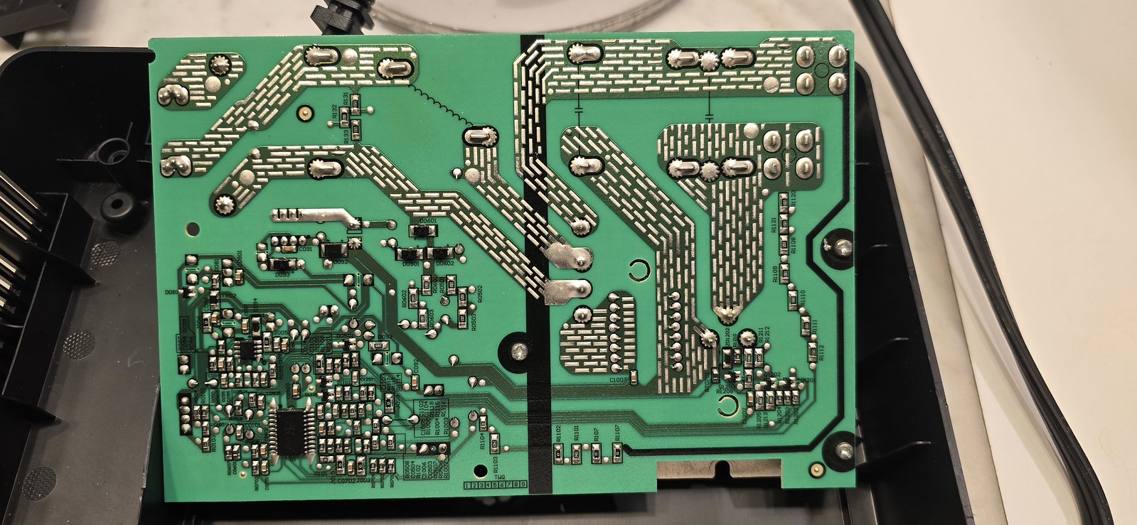
https://www.flickr.com/photos/eichin/54245499157/ Asking for someone I follow on social media: what is the purpose of the solder pattern on these traces? I believe and have read that adding solder to traces is a technique used to increase current carrying capacity, but I haven't seen anything talking about making it in a pattern like this.
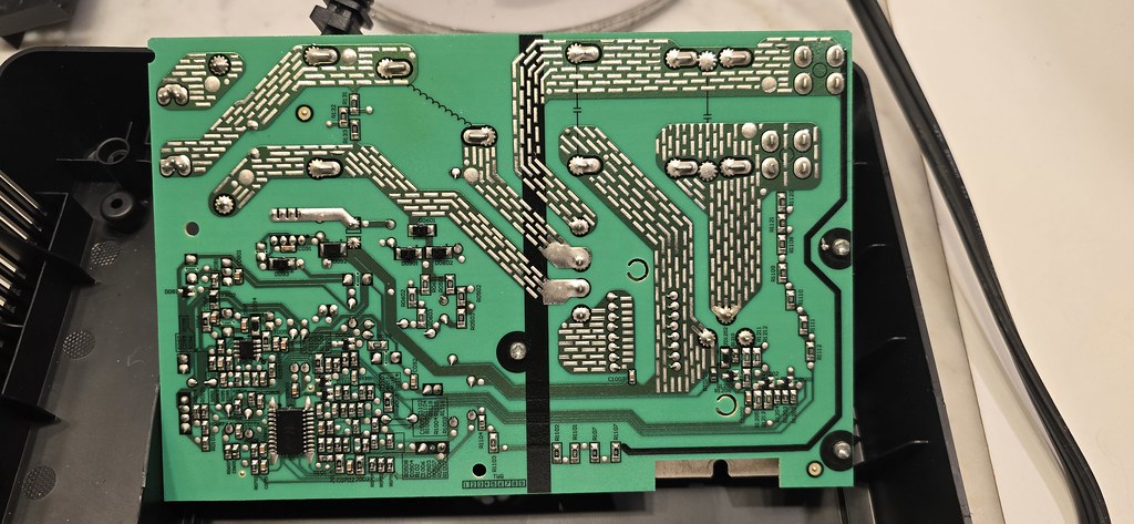
What are these dash-patterns covering big chunks of the unused areas of the board? (The upper parts have corresponding large circuit elements on the other side - it's the power stage of a "Comfee" brand induction burner.)
conversation on the socials: https://social.afront.org/deck/@eichin@mastodon.mit.edu/113771882547763101
thorny reef
Hi All, Would a fuse be recommended between the +3v7v @ 4Ah battery & switch be recommended ?.
 supple pollen
smoky roost
I'm also getting different results looking at uncoated open air conductor gap si...
supple pollen
smoky roost
I'm also getting different results looking at uncoated open air conductor gap si...
That seems reasonable as long as it stays clean and dry. I opted for ordinary 0.1" through hole connectors, and put the cathodes in two connectors and the anodes in a separate one.
 supple pollen
thorny reef
supple pollen
thorny reef
It seems like a good idea to me. Unsure what goes on J1, but the fuse position might be better elsewhere, depending
thorny reef
J1 is the battery connector 😄
thorny reef
supple pollen
That seems reasonable as long as it stays clean and dry. I opted for ordinary 0...
Oh i do like the look of an ole Nixie !!
supple pollen
thorny reef
J1 is the battery connector 😄
That makes sense: I'd put the fuse right at the battery connector, before the 3.7V bus
torpid trout
median stirrup
https://www.flickr.com/photos/eichin/54245499157/ Asking for someone I follow on...
Fascinating. Do you think it be hard to solder a huge area, so breaking it up this way is just a way to trade-off reduced current carrying capacity vs easier soldering?
median stirrup
@torpid trout I think that's a good theory anyway
supple pollen
torpid trout
Fascinating. Do you think it be hard to solder a huge area, so breaking it up th...
I'm guessing it's wave soldered, but could be tricky with an iron
thorny reef
Well that was fun .... Just spent the last hour battling my Broadband supplier as we lost the business internet.
OK, i'd like 1 final check on the power conversion & charge if posable please . I feel like i'm there. any changes or criticisms are welcome.
I have 3 Potential power sources for the supply
USB Type-C - +5vU [ NOT SHOWN ] [ Will be drawn later today] [Also handles data communication to MCU]
External IN - +5vE [ NOT SHOWN ] [ Will be drawn later today ] [barrel Jack]
Battery - +3v7B Fused & Switched for safety
both +5v sources connect to the same bus [VIN] via schotkey diodes to prevent back feeding if both are connected at the same time. Vin goes directly to MCP7381T charge management chip & load sharing circuit. +3v7B connect to the load sharing circuit and the charge management chip, the output from the load sharing circuit [VCC] Connects to a TLV76701xxxxx Precision liner voltage regulator [VCC will change voltage depending on if battery or VIN is used]. this then regulates the voltage down to +3v32 [Due to adjustable version of regulator & resistors used].


 smoky roost
supple pollen
That seems reasonable as long as it stays clean and dry. I opted for ordinary 0...
smoky roost
supple pollen
That seems reasonable as long as it stays clean and dry. I opted for ordinary 0...
Thanks ! Yea first one I did was just 2.54mm header pins between the pcb with tubes and the driver ICs and resistors, and the pcb with mcu, rtc etc.
But this time a homemade Socket slots directly into a panel and has the connector at the other end of the lead.
This is what the old one looked like

Egh.. no pcb pics.. but I just attached premade prototyping boards to a base pcb so not that interesting
thorny reef
Anyone know if the suspend lines on the CP2102 USB to UART should be connected ? or can i leave them floating?.
not really sure what they are for.
unique patio
thorny reef
Anyone know if the suspend lines on the CP2102 USB to UART should be connected ?...
Those are output pins that report when the device enters Suspend mode. From the datasheet:
The USB Suspend and Resume signals are supported for power management of both the CP2102N device as well as external circuitry.
The CP2102N will enter Suspend mode when Suspend signaling is detected on the bus. On entering Suspend mode, the CP2102N
asserts the SUSPEND and SUSPENDb signals. SUSPEND and SUSPENDb are also asserted after a CP2102N reset until device configuration during USB Enumeration is complete.
you don't need to connect them to anything
thorny reef
unique patio
Those are output pins that report when the device enters Suspend mode. From the ...
Thank you, ,i did read that in the data sheet but didn't quit understand. so they can be left floating.
unique patio
yes, they are outputs, not inputs
thorny reef
unique patio
yes, they are outputs, not inputs
Does this look right ?.. DCD & RI have been grounded via 10K to prevent any interference [Although not used], VDD & REGIN Have been linked via R12 [If 0r resister is used] to suspend the internal regulator as an external +3v32 s being generated else ware. RST Has been pulled high via a 10K to prevent any interference.

ignore cap values they havent been adjusted yt.
supple pollen
I'm still boggled by chips that can support USB without a crystal
distant raven
supple pollen
I'm still boggled by chips that can support USB without a crystal
Internal oscillators are much better than they used to be, it’s amazing how much better they’ve become. Just get a 12MHz sample from the host and you’re good to go. Feels like magic anymore
Which, something interesting to me was the CHxxx chips that were used on Arduino clones ended up with more external components than the more expensive FT232R
unique patio
supple pollen
I'm still boggled by chips that can support USB without a crystal
e.g for SAMD21:
1.3.2 Crystal-less Operation
SAM D21 provides an option to use the USB SOF (Start-Of-Frame) signal as a reference signal for DFLL to generate
the required 48MHz for GCLK_USB. When the USB Clock Recovery Mode (USBCRM) is enabled in the DFLL, the SOF
signal from the USB host will be used as the reference clock for DFLL. An auto jitter mechanism is enabled with
USBCRM to manage the jitter within the USB specification limit. This feature eliminates the requirement of an external
crystal in USB device applications
 elder peak
Thanks for a ... crystal clear explanation of the situation.
latent jungle
IC what you did there.
elder peak
I mean, as a kid I wondered why the data sheets that, in my tender teenage years, I barely understood always specified so many external parts when weren't IC's magical? What's with all of those resistors and capacitors?
So it's nice to see reality catch up?
thorny reef
elder peak
I mean, as a kid I wondered why the data sheets that, in my tender teenage years...
Resistors ?
thorny reef
elder peak
I mean, as a kid I wondered why the data sheets that, in my tender teenage years...
If your referring to my schematic it to prevent any potential noise on unused pins, caps are for stability
Missed the point there 🤦🏻
 worldly schooner
Nah he’s referring to older chips’ application circuits, stuff like the 555.
thorny reef
worldly schooner
Nah he’s referring to older chips’ application circuits, stuff like the 555.
Ah, Its been a long arse couple days 😄 i missed the point on that one 😄
thorny reef
USB Routing on PCB..... can the data line just be routed willy nilly or should i use differential routing ?.
latent jungle
You should use differential and target 90 ohm impedance. However. If you're only running USB 1.1 speeds, both are less critical.
thorny reef
It the data lines for programming an ESP32 MCU
distant raven
thorny reef
It the data lines for programming an ESP32 MCU
USB pins or UART?
Also which ESP32, there’s so many variants these days
thorny reef
distant raven
USB pins or UART?
ESP-WROOM-32E Module. Both the USB & UART Apologies combined all in the term USB.
distant raven
USB IF should be 1.1 PHY so as long as they are roughly the same length and 8-10mil is size (assuming you’re using mil not mm) should be fine. UART often wants termination resistors though it will be dependent on the UART chip you use and what the data sheet specifies
I’d guess probably straight line connection to ESP32 should be fine for UART, they don’t specify anything for termination resistors
thorny reef
using a CP2102
distant raven
Ah yeah, just glanced they don’t specify resistors for RX/TX so you’re good
Whatever your minimum trace width is should be fine
thorny reef
You beat me to it ... just pulled up the shee 😄
latent jungle
if the UART signals are exposed (where you connect signals manually), then you might want to put a nominal resistor (like 22 to 100 ohms). It'll help prevent damage if you accidently swap them.
 uneven cloak
thorny reef
Well that was fun .... Just spent the last hour battling my Broadband supplier a...
uneven cloak
thorny reef
Well that was fun .... Just spent the last hour battling my Broadband supplier a...
That is really hard to read in that dark mode thing . Its easier when you look at these all the time to notice differences when they are in a similar pattern
thorny reef
uneven cloak
That is really hard to read in that dark mode thing . Its easier when you look a...
My Apologies, i suffer from several site issues, the colour pallet is attuned to me.
Anyone got as trusted source for the CP2102N data sheet ?... Silabs have restricted its access....
https://www.silabs.com/documents/public/data-sheets/cp2102n-datasheet.pdf
thorny reef
UK
distant raven
huh, shouldn't have restrictions I wouldn't think.
thorny reef
 distant raven
weird, I can access it
Maybe clear your cache and try again?
or try another browser
I can access that datasheet just fine
thorny reef
Hmm... weird done a cache clear and boom
distant raven
The internet is a fun place
uneven cloak
thorny reef
Hmm... weird done a cache clear and boom
This can be due to using a vpn as sometimes they redirect to a restricted country resetting can move it.
thorny reef
uneven cloak
This can be due to using a vpn as sometimes they redirect to a restricted countr...
Haven't had this issue before unless i changed a setting somehow without knowing [Probably], all my VPNs are set to split tunnelling, everything else goes through them Bar brave browser.
The Battery charge detect on the CP2102N........ How would i attach it to the MCP73031T.... Im assuming i put the prog resistors from lowest setting to highest settings on the output of the NPNs to the prog pins?.
again sorry for the multiple questions., looking at pages 8 / 9, I now require a voltage divider for the cp2102N ?.. I cant just tie vbus straight to usb vbus?.
 thorny reef
distant raven
thorny reef
distant raven
Apologies another meeting !!, R5 & R1 ... Specific values, have they got to be bang on or can they be about ?
distant raven
As close as possible
thorny reef
distant raven
As close as possible
Danke, i have come up with this design i 'm hoping will be suffice ?.
 distant raven
thorny reef
Danke, i have come up with this design i 'm hoping will be suffice ?.
distant raven
thorny reef
Danke, i have come up with this design i 'm hoping will be suffice ?.
VRegIn should connect to 3.3V, not VIN
thorny reef
Page 8..... From my interpretation VIN [ VBUS in. there case ] goes straight to VREGIN?.....

My VBUS is a combination of USB / potential External +5v source
 distant raven
thorny reef
Page 8..... From my interpretation VIN [ VBUS in. there case ] goes straight to...
distant raven
thorny reef
Page 8..... From my interpretation VIN [ VBUS in. there case ] goes straight to...
It can, yeah. I personally like using 3.3V on VRegIn
thorny reef
Fair play, Phew..... Thought id misunderstood that then !!. The main reason i've gone with VIN the chip wont be powered when running on battery,
 kind kernel
Sorry if this has been discussed. I need help prototyping a PCB board with multi layers of logic. I am completely self taught using Adafruit stuff. Does any one know an affordable business, or person I can talk to about it? A learn/pay them to autocad the board I want to make and then we both win.
I’m specifically having trouble with… well logic paths. Also I need to up convert an Analogue input to between 5v 2w to 9v 2w
So the signals never stop coming. Then they go down the wrong umm rivers. Or paths. If this is also the wrong place, I am sorry.
worldly schooner
kind kernel
Sorry if this has been discussed. I need help prototyping a PCB board with multi...
If there’s a specific question about something in a design, feel free to ask for help here. Routing of nets can be tough, but if you post pictures of what you have I’m sure we can offer suggestions.
As for the conversion of analog voltages, that’s definitely something that we can advise on. Could you be more specific regarding what kind of analog input you’re trying to convert?
kind kernel
To answer your question it from a pin on the pi zero. I kind of tried to make my own project to learn some random things I want to learn, but I’m realizing I’m taking on too large a project. Especially with a recent new job. Thank you for your time tho.
I’ll go back and do the logic gate learning stuff a few more times and come back to you with a… obtainable project.
Oh the single is intermittent because it was attached to a sensor.
In my idea it uses some of the sensors on adafruit to help with home made 3D printed prosthetics.
So intermittent signal gets turned into watts that are a little specific because I don’t want to burn the kids.
The more analogue it is the better it seems to be when it comes to basic daily wear and tear
It needs a battery, but the more versions randos like me make the better the real folks can make.
worldly schooner
kind kernel
To answer your question it from a pin on the pi zero. I kind of tried to make my...
Please correct me if I misunderstood anything. You have a sensor and some kind of 5-9V motor or servo, and you want the circuit to directly translate the sensor output to some motor output, is that right? What kind of sensor are you using?
kind kernel
You are correct, but I’m realizing I got the logic stuff is incorrect so the math is incorrect. Thats why I ended up here. Because it was all strange. What sensor I had not figured out yet either. I’ll regroup, and hopefully find a local I can ask.
Thank you
thorny reef
Should ESP32 Modules be mounted all on PCB with clean ground underneath antenna or with a cutout ?.

 supple pollen
You don't want a ground plane under the antenna, so either a cutout (no PCB at all) or PCB without any traces or planes should be okay (I think no PCB at all is preferred, which is why many designs simply hang the antenna off the edge of the PCB)
unique patio
thorny reef
Should ESP32 Modules be mounted all on PCB with clean ground underneath antenna ...
don't put any copper underneath the antenna. See the guidelines here: https://docs.espressif.com/projects/esp-hardware-design-guidelines/en/latest/esp32/pcb-layout-design.html#positioning-a-module-on-a-base-board
thorny reef
unique patio
don't put any copper underneath the antenna. See the guidelines here: <https://d...
Boom Thank you !!, That was the document i was looking for !! couldn't remember where i saw it !!
thorny reef

 stark arch
how easy do you guys think this would be to hand solder? I've mostly done only through hole stuff before: do you think this module is realistically hand solderable? https://www.seeedstudio.com/Wio-SX1262-Wireless-Module-p-5981.html

The Wio-SX1262 is a LoRa wireless module based on the Semtech SX1262 chip, supporting LoRa & LoRaWAN frequency from 868 to 915 MHz. Equipped with an onboard IPEX antenna connector and high-quality components like the TCXO, it ensures stable operation even under harsh conditions. Suitable for industrial, agricultural, smart home, and other long-r...
worldly schooner
stark arch
how easy do you guys think this would be to hand solder? I've mostly done only t...
Definitely hand solderable. As far as surface mount is concerned, it doesn’t really get much easier than this.
Castellated holes offer easy access to both pads, while the larger module is far easier to position by hand compared to smaller passives that need tweezers to be held down in place.
Better yet, concave holes are hard to bridge on purpose, let alone by accident.
stark arch
worldly schooner
Definitely hand solderable. As far as surface mount is concerned, it doesn’t rea...
betttt
haven't soldered casselated before so wanted to confirm before purchasing
pale grove
I got one additional question:
- I was looking at some board schematics with USB-C connectors and noticed that sometimes on some a MBRX120 diode is used between the USB and VBUS line. And on some PCBs not. Is there a reason for that?
supple pollen
You'll often see that or a MOSFET used on boards that have the option of an additional power source (such as a LiPo cell), to avoid back-powering the USB connector.
 rancid lagoon
How would i switch (enable and disable) headphone level audio signals from a microcontroller like an attiny for example with minimal quality loss
Like the audio comes in one end and goes out the other but can be disabled by the attiny
supple pollen
You can use an analog switch IC or relay. If it's unipolar, you can shunt it to ground with a transistor.
rancid lagoon
relay is too big
 charred merlin
Reed relays are fairly compact, or can be.
stark arch
currently trying to figure out clock stuff for my stm32 project and was wondering, what clock speed should I select for my SDIO? I understand the max for high-speed is 50MHz, and for standard it's 25 MHz. I'm currently debating between 24 and 48 (although I can go lower)
supple pollen
It depends somewhat on what you're talking to: some devices can support higher speeds than others.
distant raven
It’s interesting to me that SDIO is just a flavor of SPI.
Not 100% SPI but definitely SPI like
stark arch
I mean I'm guessing the limiting factor would be routing because it was not routed for high-speed. I'd just be writing to an micro SD card
distant raven
SDIO technically would provide the benefit that the IO lines are bidirectional compared to conventional SPI. But there are definitely trade offs.
stark arch
do I just need pull-ups for the data lines that aren't being used for SDIO if I'm only dong a 1 bit bus?
and CLK doesn't need a pull-up right?
distant raven
Looks like just CMD and DAT0 need pull ups
stark arch
distant raven
Looks like just CMD and DAT0 need pull ups
so none needed for D1-3 if I'm not using them?
distant raven
Right
 blazing kayak
Hello. I am new to maker stuff and have no formal electronics experience. So far I am building a project on a breadboard, though I have come to realize that the microcontroller I am using (ESP32 Nano), cannot output greater than 3.3v.
However one of my relays is rated for 5V. This is fine however as I am using an external power supply at 5V that powers the esp, and the relay (but uses an NPN to take a 3.3v digital signal from the esp and complete the circuit from the relay to the power supply.
This works fine! But it means I have to use a power supply and not USBC, as I am aware that the ESP can only output 3.3v, I cannot get 5V unless I use a powersupply.
However I am looking to add a standalone USBC connector which powers both the esp and the relay. I was wondering if there are anyways to regulate the input voltage to ensure it stays at 5V, as I am aware USBC can go higher than 5V
distant raven
blazing kayak
Hello. I am new to maker stuff and have no formal electronics experience. So far...
What ESP board are you using?
Many dev boards from Espressif bring VUSB out to a header
unique patio
blazing kayak
Hello. I am new to maker stuff and have no formal electronics experience. So far...
USB-C will deliver more than 5V if certain programming resistors are set up to specify that. It doesn't happen without that.
blazing kayak
distant raven
What ESP board are you using?
Esp32 Nano
blazing kayak
unique patio
USB-C will deliver more than 5V if certain programming resistors are set up to s...
Ah okay. so if I can just put a usbc module or something on my board it should work fine? I dont need any other circuit
unique patio
blazing kayak
Ah okay. so if I can just put a usbc module or something on my board it should w...
there are 5v power supplies that have USB plugs. I'm a little confused. Is this the board you are using? https://store.arduino.cc/products/nano-esp32
blazing kayak
unique patio
there are 5v power supplies that have USB plugs. I'm a little confused. Is this ...
Yes.
unique patio
you can get 5v from the VBUS pin on that board. It comes from the USB connector.
blazing kayak
unique patio
you can get 5v from the VBUS pin on that board. It comes from the USB connector...
oh-
okay thats actually really good
stark arch
distant raven
Right
how sure are you that d1-d3 don't need pullups if they're not used? seeing a-lot of conflicting opinions online
blazing kayak
@unique patio Thank you again, you saved me a lot of hassle. I thought I had to use an external power supply to power this relay!
unique patio
You’re welcome!
distant raven
stark arch
how sure are you that d1-d3 don't need pullups if they're not used? seeing a-lot...
STM32 recommended circuit for 1 bit SDIO showed pull ups but were tagged as DNP (do not populated)
stark arch
distant raven
STM32 recommended circuit for 1 bit SDIO showed pull ups but were tagged as DNP ...
perfect, thank you for the help
kind kernel
worldly schooner
Please correct me if I misunderstood anything. You have a sensor and some kind o...
Turns out my math was correct. Go adafruit learning systems. I accidentally made a transducer and made something like this. https://blog.piezo.com/piezoelectric-floor-tiles-and-harvesting-energy-from-pedestrians?hs_amp=true
Can you harvest energy from walking? Check out these resources to get a better understanding of piezoelectric floor tiles and energy harvesting.
blazing kayak
Any reccomended Ferroelectric RAM modules for ESPs?
unique patio
blazing kayak
Any reccomended Ferroelectric RAM modules for ESPs?
we sell some breakouts: https://www.adafruit.com/search?q=fram+breakout. What is your goal?
 regal lodge
with a 1k resistor is there a reason why would they still be quite bright?

just in case it matters, these aren't being PWMed, they are power indicators:
 latent jungle
regal lodge
with a 1k resistor is there a reason why would they still be quite bright?
latent jungle
regal lodge
with a 1k resistor is there a reason why would they still be quite bright?
Blue LEDs are incredibly bright. I use 4k7 with them.
regal lodge
I was trying to keep the number of parts in the BOM down, the resistor values already being used are: 510/560, 1k, 5k1, and 10k
ideally I'd like to balance them as well so the 3.3V and 5V are roughly the same brightness
latent jungle
Also, blue isn't a great choice for 3.3 volts.
regal lodge
it is a bit dim
it's hard to tell in pics but you can kind of tell it's dimmer than the LED above it
 latent jungle
Yeah, its 2 mA versus 300 uA ...
so about 15% difference (although, I don't think the relationship is that linear)
distant raven
The relationship of perceived brightness is logarithmic
But that’s the lumen measurement. microcandela is probably a better measure of brightness
 inland harness
I am having trouble with this circuit board that I have. I want to access uart, but it's acting funny


I have the datasheet and have connected to rx, tx, and ground.
https://www.microchip.com/en-us/product/PIC18F24J10
https://ww1.microchip.com/downloads/aemDocuments/documents/OTH/ProductDocuments/DataSheets/39682E.pdf
https://ww1.microchip.com/downloads/aemDocuments/documents/OTH/ProductDocuments/Errata/80269c.pdf

Ideal for customers that require low cost, high speed, and enhanced serial communication peripherals. The PIC18F24J10 runs at 40MHz at 3V and has an enhanced USART with LIN capability and two synchronous serial ports with address masking for the I2C. I ...
inland harness
Is EUSART the same as UART?
unique patio
inland harness
Is EUSART the same as UART?
The "E" is just "Enhanced". Looks like it can be a regular uART
"acting funny" covers a wide variety of ills
inland harness
I provided a video for the 'acting funny' part
nothing at all shows up on the screen when i plug it in and turn it on
unique patio
did you connect TX->RX and RX->TX? Do you have the baud rate correctly set?
is the voltage level what you expect?
inland harness
I do not know the baud rate, but I'd assume that I would be at least getting garbled data
I tried a whole bunch ofthem
Yes the voltage is 3v3
I am powering it with the onboard power supply though
unique patio
as long as the grounds are tied together, that should be ok. If you have a scope or a logic analyzer, that would be helpful to see if there's data on the lines
inland harness
I don't have a scope
unique patio
are you sure about which is TX and which is RX?

 unique patio
LEDs on the board or the USB-to-serial adapter
inland harness
On the adapter
inland harness
Yeah swapped them, same behaviour
There is continuity between ground and the ground pun that I'm connecting to
inland harness
unique patio
that's kind of my whole checklist of what to try
Maybe this isn't a uart interface?
Could it be a SPI flash point?
unique patio
well, I have no idea, i don't know anything about the board. So a logic analyzer or scope would help. Do you have a schematic for the board?
inland harness
I do not think the schematics are publically available
unique patio
most microcontrollers have multiple functions on a pin, so though it could be a UART it might be used as something else.
inland harness
You would disapprove if you knew what I'm trying to do 🙂
unique patio
well, I don't think I can help you any more anyway.
inland harness
Here's what the board is from

I am trying to increase the float voltage by a bit
There should be some sort of calibration programming mode that I can access to raise it
unique patio
without adequate documentation, this is a slog, and could be dangerous.
inland harness
Yes I know
There's a big transformer in there

I'm not even getting close to it

Here's how I connected to the pins (continuity is correct)
unique patio
if you don't know anything about what's going on, then I'd say give it up. Given that there isn't already a connector there, it's probably not what you think. Factory progrmaming would have some headers or pins to use
inland harness
There IS a header there
This older model has one too


I was hoping to do this: https://youtu.be/MRk-OXfKy4o

Tired of APC UPS's cooking or boiling batteries dry. I found a way to adjust the float voltage as not to ruin the battery or batteries.
There is a guy who has a lot of valuable information on the net as well.
http://technician-john.blogspot.com/2012/11/troubleshooting-apc-ups-and-other-upss.html?m=1
Be sure to know your desired float voltag...
thorny reef
Howdy All, I have a Q for all. under normal circumstances i know you route USB D+ & D- as differential pairs.... I'm in the middle of laying our a custom board for a project, I have USB Data going from Type C to a CP2102N. Since it is a tiny run does it still need Diff pairs & can a VIA be placed in line?.


 supple pollen
inland harness
I was hoping to do this: https://youtu.be/MRk-OXfKy4o
supple pollen
inland harness
I was hoping to do this: https://youtu.be/MRk-OXfKy4o
Did you try sending "B"?
inland harness
supple pollen
Did you try sending "B"?
Does it have to be a capital B...?
Because I didn't do that
No matter what key I pressed, there was no repsonse
It's the same company but probably a different interface.
supple pollen
I'd try a bunch of different speeds too.
One bit of industrial kit I reverse engineered wanted data at 600bps. I had to hack up my terminal program, as it didn't offer that option.
inland harness
I'm using picocom it allows any arbitrary baudrate
I don't have a signal analyzer
I have an rtl-sdr...?
If changing the voltage via software won't work, I've heard of a way to do it by replacing a 100 ohm resistor with a 200 ohm potentiometer
And then adjusting the screw to the exact voltage
I would not be opposed to doing that
supple pollen
That may be your easiest way forward. They make a bunch of these things, and they're not all alike.
Why do you want to increase your float voltage? It seems to me it would just kill your batteries even sooner (APC equipment is notorious for being hard on batteries as it is)
inland harness
supple pollen
Why do you want to increase your float voltage? It seems to me it would just ki...
Hahahahaha not telling
You'll be mad at me
supple pollen
Heh, I may have just figured it out...
supple pollen
My electric tractor used to be lead acid, now it sports 4.4kWh of LiFePO4.
 inland harness
I replaced the batteries in my great aunt's stairlift with 2 12v lifepo4 batteries. Then I tested the battery life...
Those little 7ah server ones
Whoops
supple pollen
Annoyingly two of the ESCs don't like getting 57V instead of 48(ish), so it runs in turtle mode until the battery runs down a bit. Still figuring out how to reprogram them (the manufacturer only wants to share info with OEMs)
inland harness
I overheated and killed the motor mosfets after 1 full hour of going up and down the steps without a break
Batteries were at about 80% still
The lead acid batteries would have lasted like 4 trips max...
I did 200 at least
They're still in there too!
supple pollen
The lead acid batteries in the tractor provided decent runtime, but a set would only last two years, and buying a quartet of AGM batteries every 2 years is expensive (that LiFePO4 pack wasn't cheap, but it should last a long time)
inland harness
Yeah I don't need CCA on my battery backup systems
supple pollen
That pack is specced for 92A and the tractor can theoretically draw 125A at full beans but I haven't had any problems
inland harness
My battery backup has an overload light at 10a. The batteries can provide 15a
The issue is that the box charges them at 13.7v
Even 14 is fine
 supple pollen
The charge algorithm (such as it is) isn't a terribly good match but you presumably already knew that
inland harness
Yes. Actually, it doesn't matter since the BMS in the battery is built to handle it
The XZNY batteries are really good
supple pollen
The Inventus one I got is pretty nice too, but I did spring for a matching charger.
inland harness

It's a reputable brand
They respond to emails promptly, and it's an actual person
Tenergy is another high quality battery brand, but they do those alkaline zinc batteries
supple pollen
I'm always leery of counterfeits from spamazon.
inland harness
Well they perform better than Duracell in an Xbox controller
And they last longer in a wiimote than those lithium energizers
I've actually had more luck with the counterfeit stuff than the OEM stuff.
Like the removable lenovo batteries nuke their BMS controller if you disconnect a cell, but the counterfeits don't.
Same thing with the makita batteries
I specifically bought a counterfiet makita battery to replace the cells in. It came with low quality cells.
Anyway, back on topic. How do I find the correct resistor to replace?

There are a lot of components here
inland harness


It looks like the transformer is not needed at all to charge the battery

Could it be r40?

On one side of r40 is the 13.7v line
This seems like one of those battery charging circuits, but I don't know how those work
supple pollen
inland harness
Anyway, back on topic. How do I find the correct resistor to replace?
Track down the charge controller chip, look up its data sheet, find the current programming pin, then buzz out the board to find the resistor(s) connected to it (they'll generally be near the chip)
inland harness
supple pollen
Track down the charge controller chip, look up its data sheet, find the current ...
I don't think there's a charge controller chip...
I think it's just diodes and a resistor.
And transistors
supple pollen
Might have to reverse engineer the circuit a little, or use a "try and see" approach by paralleling resistors onto the existing resistors and seeing the resulting difference(s)
latent jungle
 lyric nymph
Something that bothers me about your PCB layout is how little copper you gave the tab. The tab is there for heat dissipation and not to provide current. #help-with-projects message. If the ESP draws 100 mA that means the package is going to be dissipating 700 mW through that little tab to the small amount of copper you put on the PCB.
Your traces should have had the load coming from Pin 2 with the tab going to a large copper area.
That said, Dr. Lui did some testing of that part (compared to an AMS1117) and found it was more robust. (Also at the end you can see what the inside of the package probably looks like.) https://goughlui.com/2021/04/09/tested-stmicroelectronics-ldl1117s33r-sot-223-3-3v-ldo-voltage-regulator/
I would also strongly encourage you to re-work the layout to:
- Get the input and output capacitors closer to pins 2 and 3.
- Use large copper zones instead of traces for the input and output voltages
- Mentioned above, create a nice big copper zone for the tab to sink heat into
I can't say for sure that has anything to with the LDL failing, but the existing layout isn't helping, either.
lyric nymph
This defies my (admittedly limited) understanding of how voltage regulators work. I wasn't aware that an LDO spec'ed at 700mA would always draw 700mA even if the components it powers don't consume that much current, and that it would then have to sink that unconsumed current into heat to be dissipated.
I have run into LDO's spec sheets which show that the amount of voltage they drop is converted to heat, and is exacarbated by the amount of current they're passing..
latent jungle
lyric nymph
This defies my (admittedly limited) understanding of how voltage regulators ...
No, that is not what I was saying.
lyric nymph
Ok, I must've misunderstood you.
latent jungle
From 12V to 5V, the drop across the regulator is 7V.
If the load draws 100 mA, then the power dissipated would be P=I * V = 100mA * 7V = 700 mW
lyric nymph
Ahhhh, okay. Yes, this matches my prior understanding. And that explains where the 700mW cames from.. And I DID misunderstand, I thought that stated 700mA! 🙂
latent jungle
yeah, my easy numbers was a bad choice in this case. 🙂
The LDL has thermal protections, so I'm dubious that the heat sinking is really the issue. But from a schematic perspective, I don't see the problem. So it must be layout related.
lyric nymph
Yeah, something is definitely causing that LDL1117 to fail... I've observed two of them behaving the same way now, which have caused 2 of my QTPY's to fry...
latent jungle
lyric nymph
Yeah, something is definitely causing that LDL1117 to fail... I've observed two...
When you tested the LDL alone, what kind of load did you use?
lyric nymph
Not much of one, honestly. I ran an Arduino Uno from it. I don't have a programmable load here.. And my benchh power supply could probably use an update as well; it's a cheaper version of this: https://a.co/d/9lnpm2F

NICE-POWER DC Power Supply Variable 30V 5A, 4 Digital Display Adjustable Regulated Switching DC Lab Bench Power Supply with 5V/2A USB Charging Port

 lyric nymph
While I have no qualms about spinning the board, I'm not sure I'm confident that the simple layout change will prevent the LDL1117 from failing ..
supple pollen
You can extend the trace for the 5V pin under the device to meet up with the tab if you like
thorny reef
Are layout examples written in stone or are they just manufactures recommended?.
I I only ask as i'm routing all power through Layer 3 of a 4 layer board.....
How would i keep this layout with vias?.,
Can a single via take a max of 1A @ +3v3?
Would a couple of vias help split the load ?.
latent jungle
lyric nymph
While I have no qualms about spinning the board, I'm not sure I'm confident t...
THe next test you need to do is load the LDL to see if it continues to fail. Start with 1 kohm, then go to 100 ohm, then 47 ohm.
latent jungle
thorny reef
Are layout examples written in stone or are they just manufactures recommended?....
For a SMPS, they should be followed as closely as possible. Vias are very common to tie planes together. Many small vias are better than fewer large vias.
lyric nymph
latent jungle
THe next test you need to do is load the LDL to see if it continues to fail. Sta...
I'm not sure I follow..
latent jungle
lyric nymph
I'm not sure I follow..
You need to put a load on the output of the LDL. Start with a 1kohm resistor (5mA), then 100 ohms (50mA), then 47 ohms (~100 mA). To verify if it works with a load (that you can afford to lose)
 sick ravine
Is there a good generic solution to the "press button to power on press same button to power off" problem?
lyric nymph
The only resistors I have are little axial things that I don't know wwhat their rated wattage is...
Probably 1/4W
latent jungle
P = V^2 / R = 25 / 100ohm = 250 mW or 1/4.
sick ravine
sick ravine
Is there a good generic solution to the "press button to power on press same but...
Atm I'm figuring a d-flipflop connected to a MOSFET?
latent jungle
How is the flip-flop powered?
thorny reef
lyric nymph
I'm not sure I follow..
I know i keep asking 1001 questions & i apologies i keep gut checking & double checking, i'm learning so much about SMD layouts & design.... & i'm thankful AF !!
Using polygons, this would be an appropriate [ Albeit basic layout] i have to extent the pads to the resisters / MLL Caps. I have to adjust the polygons to fit the 1206 layout [ I know HUGE ] but this is the general layout, am i heading in the right direction ?.

 sick ravine
latent jungle
How is the flip-flop powered?
sick ravine
latent jungle
How is the flip-flop powered?
Way I figure the initial button press toggles the latch and the power MOSFET which feeds the latch from there
sick ravine
thorny reef
I know i keep asking 1001 questions & i apologies i keep gut checking & double c...
Putting everything with huge connections to the ground plane will make it more of a pain to solder
That's why the rule fill leaves gaps
thorny reef
sick ravine
That's why the rule fill leaves gaps
How does one adjust this ?.
sick ravine
The default before you filled it in looks fine to me
It's a setting in fill rules iirc?
thorny reef
Ill have to do some research about fill, I have removed the copper pour for now.
inland harness
supple pollen
Might have to reverse engineer the circuit a little, or use a "try and see" appr...
OH I CAN PARALLEL RESISTORS
Duh
That will decrease the resistance right
I can cannibalize some power supplies
thorny reef
sick ravine
Putting everything with huge connections to the ground plane will make it more o...


A suitable layout ?.
thorny reef
sick ravine
That's why the rule fill leaves gaps
Ive got a heat plate that ill be securing the PCB down to, hopefully put heat into the PCB making it easier to solder
distant raven
inland harness
2 100 ohm resistors don't make 50 Ohms?
R1*R2/(R1+R2) so 10000/200 =50
Yeah seems right but the caveat here is if the resistors can be counted in parallel with the resistance of the surrounding circuit, then you likely won’t directly measure 50ohms
inland harness
Hmm maybe this circuit is redundant
Anyway, I removed the resistor and it didn't change anything other than the resistance being OL (I put it back)
distant raven
With a little bit of measurement we can get a rough Thevenin equivalent circuit of the surrounding and use that in calculating in. Though always weird to me that enough distance between caps and inductors doesn’t have as direct of an influence on overall impedance
inland harness
I need to figure out which resistor is controlling the charge voltage
These are my chips


I don't think the 324a chips control the voltage
That NXP chip is a value shift register
You know, it's probably the 1431c
I don't know how to test my theory
inland harness

Could r56 be the control resistor?
Increasing resistance should increase the voltage, no?
latent jungle
the 1431 is an adjustable voltage reference
latent jungle
sick ravine
Way I figure the initial button press toggles the latch and the power MOSFET whi...
That could probably be made to work. (and might an easy but brute force path.) search for “soft power circuits”. You can get away with just two mosfets and a cap in some cases.
sick ravine
that's the keyword I was looking for thanks
distant raven
And you can definitely ignore the 74xx595
The st device is a quad op amp
TNY255 part is a switch
latent jungle
distant raven
TNY255 part is a switch
I think it’s a SMPS controller. I misread the name at first too
distant raven
Nah, circuit appears to match the recommended circuit and brand
Ah wait
My brain omitted ers from switchers
distant raven
But I had the right data sheet regardless
Which means my theory about IC4/5 being opto-isolators
I’m going to guess that the shift register does some timing into the switcher, and gets some feedback from the quad op amp
Pure guess
 distant raven
R46 feels like a great candidate
inland harness
The one labeled 152?
distant raven
Yeah
inland harness
It measures 1.5k ohms
distant raven
Makes sense, 15 * 10^2 =1,500
inland harness
Wow it's big... I might be able to solder and hotglue the potentiometer right there at the end lol
I measured the voltage there...
80v sound right?
distant raven
Yeah, that seems reasonable
inland harness
Huh i thought that sounded crazy
inland harness
Is it okay to turn it on without this resistor?
inland harness
 distant raven
Gotcha
inland harness
There is an ethernet port right there, I thought it was for that
distant raven
Is there a microcontroller on the other side?
latent jungle
maybe the op amps make it an analog charge circuit
inland harness
There's no way that they're using that yellow transformer there for this right
latent jungle
using it for what?
 latent jungle
there’s no doubt in my mind they would be.
any voltage over 60 isn’t SELV (safe …. something something voltage). So you’d used a transformer for isolation.
inland harness
Oh ok so it's gotta be one of the resistors
latent jungle
(some) DC-DC converters chop up the voltage into pulses to transfer the energy over them
are you trying to change the voltage the battery charges AT or the voltage it charges TO
inland harness
That's probably the supply of the 80v then

There's no middle layer
Some if those bad resistor placements still work and measure correctly
Would a thermal camera help in any way?

This is for a server, but from the same company
Maybe the circuits are similar?
inland harness
latent jungle
are you trying to change the voltage the battery charges AT or the voltage it ch...
Oh I missed this question. I need it to charge TO and AT 14.x volts
It's a drop-in replacement lifepo4 accessory battery
I think that's what I want
Right now it stops at 13.5-13.7v
I have a few of these units that I want to permanently-ish convert to lifepo4 using these batteries.
They're lighter, last longer, and can be deep cycled 1000s of times.

As you can see, it's not even charging to 50%
That 100% is something I can change in apcupsd

I think it needs to charge at 14.6v
The Amazon page recommended 14.4
I want to play it safe at 14.2
supple pollen
inland harness
You know, it's probably the 1431c
Yeah, that might be a voltage reference chip
Oh, Hem already pointed that out
inland harness
supple pollen
Yeah, that might be a voltage reference chip
One of the pins is 10v, another is like 2.5v
inland harness
@latent jungle do you have any other ideas?
latent jungle
inland harness
<@312943079160283137> do you have any other ideas?
Sorry. no.
inland harness
Aw
I'll keep trying stuff
I thought that maybe adjusting the voltage on PIN 8 might work

That chip only outputs 10v
blazing kayak
Anyone know where to actualy purchase an MT3608? I can only find preassmbled breakout boards.


 open marten
i bought a pi 500, a siberdeck for pi 400/500, and a Adafruit NeoDriver - I2C to NeoPixel Driver. im looking for all the compatable RGB strips that i can use with this setup and has the 1-(max leds for my setup). pleses give me a list of strips that match my hardware with there price in usd.
worldly schooner
open marten
i bought a pi 500, a siberdeck for pi 400/500, and a Adafruit NeoDriver - I2C to...
Any neopixel or ws2812-compatible strip from adafruit to aliexpress should work with the neodriver, assuming a suitable power supply. Would it be possible to narrow down what you want?
open marten
@worldly schooner I want to power just from the pi no power supply. i plan to power the v input from the pi's 5v pin.
thorny reef
Blind / Buried vias, do they still conduct between layers ?. they are just hidden with in the board ?.
worldly schooner
open marten
<@98211350907490304> I want to power just from the pi no power supply. i plan to...
What power supply are you using to power the pi?
Is there a number or a length you want to cover?
open marten
@worldly schooner I'm probably going to power my pi from a topical 5 volt usb power. i don't really care the number of leds or the length of the strips. im just seeing my options with what i have and know my hardware limits.
distant raven
thorny reef
Blind / Buried vias, do they still conduct between layers ?. they are just hidd...
In what way do you mean?
I would also note that blind/buried via are expensive
thorny reef
I was unsure what blind vias acc did.... found out 😄
worldly schooner
@open marten I wouldn’t draw more than 2 amps max from the 5v pins, but the more important limit is how much current your “typical” power supply is rated for and how much current your pi draws. If you’re playing games on the pi 5, running too many neopixels off the same supply could cause brownouts.
open marten
worldly schooner
<@816788988580986880> I wouldn’t draw more than 2 amps max from the 5v pins, but...
what is brownouts?
worldly schooner
open marten
what is brownouts?
Brownouts are when the voltage dips below the minimum operating voltage, causing your system to reboot unexpectedly. They tend to happen when you draw too much current from a power supply.
open marten
worldly schooner
Brownouts are when the voltage dips below the minimum operating voltage, causing...
so then what is the best sweet point of max rgb amount with every led maxed?
worldly schooner
open marten
so then what is the best sweet point of max rgb amount with every led maxed?
Maxed? I don’t think you’ll ever need that much brightness indoors, but worst case is around 60mA per LED. Assuming you are using the usb supply, you’re probably going to be limited to an amp of current, so 1000/60= around 16 neopixels.
It’s worth noting that this I many devices use way more than 16 pixels because even 20% brightness is more than enough indoors, and rarely are they pushing every color channel to its max at once.
open marten
so @worldly schooner if i use 20% brightness how many can i run at ones on 2 amps? most of my usb power devices use 2 amps.
worldly schooner
open marten
so <@98211350907490304> if i use 20% brightness how many can i run at ones on 2 ...
2000/12 =166? Using 2A leaves very little for any other usb devices you might need to use on the pi, though.
open marten
@worldly schooner the RGB strips are going to be controlled over i2c with the Adafruit NeoDriver - I2C to NeoPixel Driver not any of the USB ports on the pi 500, but the power for the pi, is going to be powered over USB, and the pi is going to be use for portable coding (python and scratch "for my nephew") and playing just Minecraft (with a few mods. if i can do that on the pi 500). the OS is going to be the default pi OS which is based on Linux, and I'm a windows user so Linux is a little difficult for me.
worldly schooner
open marten
<@98211350907490304> the RGB strips are going to be controlled over i2c with the...
Minecraft does have some respectable cpu load, so I would stay a bit more on the conservative side of power estimates. That being said, you can go as high as a 144 pixel strip at 10% brightness, so you should have a lot of options to play with.
open marten
@worldly schooner thank you for your help so any rgb strip on anyfruit will work and be fin?
worldly schooner
open marten
<@98211350907490304> thank you for your help so any rgb strip on anyfruit will w...
Yes, and if it’s too long a strip you can either reduce brightness or cut the strip shorter.
open marten
worldly schooner
Yes, and if it’s too long a strip you can either reduce brightness or cut the st...
ok thanks
 native plover
I've got a Feather (https://www.adafruit.com/product/5691) and I want to connect my own 5V supply to the USB and GND pins, as the guide suggests. But ideally, I'd like to avoid any problems when the USB gets plugged in. Would it help to provide only something like 4.5V to VBUS and put a Schottky diode in between, so that the higher 5V from USB can block the battery my power supply when plugged in?
tulip swift
worldly schooner
Yes, and if it’s too long a strip you can either reduce brightness or cut the st...
Or since they are addressible LEDs simply don't address the last xx number of LEDs you don't want on.
tulip swift
native plover
I've got a Feather (https://www.adafruit.com/product/5691) and I want to connect...
Yes that would work. As long as you have the schottkey diode in line with the voltage you are feeding and that voltage is lower than the USB voltage. Either your voltage or the USB voltage should cut off the battery from powering the board but still will charge the battery (from looking at the schematic).
native plover
tulip swift
Yes that would work. As long as you have the schottkey diode in line with the vo...
Sorry, misunderstanding. My bad. My 5V also come from a battery, but I don't want to use the built-in charger. I want my battery-powered power supply to be cut off when I plug in the USB.
tulip swift
native plover
Sorry, misunderstanding. My bad. My 5V also come from a battery, but I don't wan...
Ah gotcha. Yes so long as the "+5V" battery voltage is lower than the USB voltage, USB wins. 👍
blazing kayak
inland harness
The chip?
Yeah, i looked at digikey even
native plover
tulip swift
Ah gotcha. Yes so long as the "+5V" battery voltage is lower than the USB voltag...
Awesome, thanks 🙂
 sharp jasper
What battery connector do this board use ?
 unique patio
sharp jasper
What battery connector do this board use ?
unique patio
sharp jasper
What battery connector do this board use ?
It is a JST 2-PH socket. Note that LiPo battery polarity is NOT standardized. All the batteries Adafruit sells are wired the same way, but random batteries you buy elsewhere may have the leads reversed. Reverse polarity will damage the board.
 winged vine
unique patio
It is a JST 2-PH socket. Note that LiPo battery polarity is NOT standardized. Al...
winged vine
unique patio
It is a JST 2-PH socket. Note that LiPo battery polarity is NOT standardized. Al...
A while back I made a feather board that used an LM66100 ideal diode to do reverse polarity protection and to switch between battery and USB power. Downside was that when USB was disconnected battery power was applied to the USB port which isn't the best idea. Do you know if there are any other downsides to adding reverse polarity protection other than extra components = extra cost and space?
unique patio
winged vine
A while back I made a feather board that used an LM66100 ideal diode to do rever...
You have the diode voltage drop, and you have the current limitation of the max safe current the diode can handle. I can't think of another issue.
winged vine
unique patio
You have the diode voltage drop, and you have the current limitation of the max ...
I mean that is why I used the ideal diode. It can handle quite a bit of current with very low voltage loss. But I can see space being a big constraint in the case of a feather.
unique patio
winged vine
I mean that is why I used the ideal diode. It can handle quite a bit of current ...
two diodes would solve powering the USB port. This kind of protection was omitted from the Feathers for both cost and space reasons, and limited use cases, I assume. There's plenty of room on the bottom of the board but that also increases cost
 echo zephyr
is it fine if i ignore the bottom part of this switch circuit?
 unique patio
echo zephyr
is it fine if i ignore the bottom part of this switch circuit?
unique patio
echo zephyr
is it fine if i ignore the bottom part of this switch circuit?
is that switching the battery? You have to connect both terminals of the battery.
echo zephyr
what do you mean?
unique patio
i don't know what's connected to that circuit
distant raven
I think I would connect the ground pin to ground at the very least, do a high impedance path to ground at a minimum for ESD sake (not super critical but can be a great design habit to have for shielding.)
echo zephyr
i haven't made any connections yet but it's meant to turn on/off an rpi pico, and optionally charge the battery if connected to power
distant raven
so like a 1Mohm resistor and a 0.1uF capacitor in parallel.
unique patio
so the terminals on the left are connected to the battery, and on the right to the board?
echo zephyr
yes
unique patio
so if you don't connect the negative terminal of the battery to ground (on the board), then it won't work
it's like touching a light bulb to only one terminal of a battery
echo zephyr
unique patio
so if you don't connect the negative terminal of the battery to ground (on the b...
i know, i would normally connect the plus to the button, then to the pico, and connect the ground straight to the pico
with this switch do i also have to connect the ground to the switch too?
distant raven
yes
unique patio
that is what the schematic means. Do you mean the switch has a third terminal?
distant raven
it's probably shielding
unique patio
could you give us a web pointer to the switch?
echo zephyr
the link to the part (switch)?
unique patio
yes
echo zephyr

LCSC Electronics
TS-1045-A13B3-D2 Yuandi - With bracket 10mm Round Button Horizontal attachment SPST 250gf SMD Tactile Switches Tactile Switches. Check out the in-stock pricing and datasheet for electronic components from LCSC Electronics.
distant raven
Ah yep, shielding
echo zephyr
ooh
unique patio
i think it's just the switch case
There is no terminal 3 here: https://www.lcsc.com/datasheet/lcsc_datasheet_2409302332_Yuandi-TS-1045-A13B3-D2_C557898.pdf
TS-1045-A13B3-D2 Yuandi $0.0975 - With bracket 10mm Round Button Horizontal attachment SPST 250gf SMD Tactile Switches ROHS datasheet, price, inventory C557898
distant raven
in that case, I definitely recommend that ESD trick for a high impedance path to ground (1Mohm resistor and capacitor) since it can transfer ESD to the device
unique patio
I think that's momentary switch?
unique patio
that is not an on-off toggle switch
echo zephyr
oh oops i mixed up something else
the button isn't meant for turning on/off the device
it just connects to a GP pin for checking if its pressed or not
mb
 paper maple
quick question, is there a way to wire up an external boot & reset button on a metro esp32-s3? I'm hoping to avoid having to crack open the enclosure holding the board.
native plover
paper maple
quick question, is there a way to wire up an external boot & reset button on a m...
For resetting, there's a pin on the side and another one in the ICSP header.
paper maple
I think I need the boot/reset combo to be able to reprogram?
native plover
I don't think the boot button is used much. You can even update the UF2 with just the reset button. Seeing the Neopixel would help, though.
paper maple
I've just been doing the hold boot/reset, release reset then release boot to get into programming mode. Would love if there was an easier way 🙂
 clever shadow
I want to use an EL357 opto ( https://www.mouser.com/datasheet/2/143/201407061738295695-365680.pdf ) to have a 24V isolated input.
How do I know how low of a current I can get away with for the LED inside? It's just driving an input to an AVR.
supple pollen
clever shadow
I want to use an EL357 opto ( https://www.mouser.com/datasheet/2/143/20140706173...
You can use the current transfer ratio from the data sheet, along with how much current your receiver circuitry requires. If it's a 5V AVR and you use the circuit in figure 10 with a 10kΩ load resistor, the phototransistor would need to conduct 250µA or so. If you're using the least sensitive version of the EL357 (the "N" one), it has a minimum current transfer ratio of 50%, so you'd need to push 500µA through the LED. You can tweak this with higher load resistors, different versions of the opto, or a Darlington connection to boost current gain.
thorny reef
Hio All, Pullups on I2C operating at +3v3. 4.7K?
clever shadow
supple pollen
You can use the current transfer ratio from the data sheet, along with how much ...
Oh wow! So even 1mA would be plenty of current to drive the opto LED in that case.
So a 22k resistor would be fine in that case.
supple pollen
That should work, yes.
 exotic tapir
does 360 pots exist?
worldly schooner
exotic tapir
does 360 pots exist?
They do, but they aren’t as common today due to the affordability and durability of magnetic encoders.
https://tech.alpsalpine.com/e/products/detail/RDC803101A/ uses two potentiometers out of phase to cover any dead zones, allowing for position detection anywhere in 360 degrees.
RDC80 Series RDC803101A Type : Through shaft type ・ Terminal style : Reflow ・ Linearity guarantee range : 330゜ (1-phase) 360゜ (2-phase) ・ Linearity : ±3% ・ Operating life : 20,000 cycles
open marten
Question: can wled work with matrix portal s3 with a 32x32 led matrix?
unique patio
open marten
Question: can wled work with matrix portal s3 with a 32x32 led matrix?
There's a fork which does support HUB75, but I don't know much about it: https://mm.kno.wled.ge/2D/HUB75/
it seems to be a "playground" for new features
open marten
@unique patio i uploaded the bin file via the "/Adafruit_WebSerial_ESPTool" and now the board keeps disconnecting over and over what is wrong?
unique patio
open marten
<@329766224093249548> i uploaded the bin file via the "/Adafruit_WebSerial_ESPTo...
I don't know. I just found out about that by doing a websearch. I haven't tried it myself. It could be that the build is wrong for the Matrix Portal S3. We have zero experience with this Moon Module thing.
did you erase the board before uploading the .bin?
open marten
@unique patio yes
unique patio
wled has its own discord
open marten
and the website didn't give me a Streat step by step guide.
rancid lagoon
recommendations for a good 3.3v polarity protection diode? it's for a rp2040 so not too much current (sending this again because my internet appears to have eaten it)
i don't really know what i should be looking for
is polarity protection the right word for a diode that stops power from one source feeding into another source?
distant raven
That’s essentially the operation of most diodes. Generally speaking, Schottky diodes are most often used to prevent back powering voltage buses
sick ravine
What impedence should I use for ferrites in analog power supplies to small ICs?
eg, like this little schematic grabbed from one of the many adafruit boards

1.5kohm?
distant raven
sick ravine
What impedence should I use for ferrites in analog power supplies to small ICs?
...
It depends a lot on the surrounding circuit. The kids of ferrite beads I see most often used are either 120ohm @ 100MHz or 60ohms @ 100MHz, they’re pretty good general purpose ones
Keep in mind that the frequency introduced into the circuit is going to change the characteristic impedance of the ferrite bead so your mileage can vary a lot
sick ravine
yeah
like realistically I'd probe it or something
but I don't have the board lol
it's powered primarily off a LDO linreg so the supply should be pretty clean... I don't think anything should be dumping a bunch of noise on the line
distant raven
Given that it’s for an analog supply, 120ohm 100MHz is probably a safe bet
sick ravine
👍
distant raven
Personally, I’d do two test boards. One with 0ohm jumpers in place of the FB and one with the ferrite beads
sick ravine
there's a thermistor plug up here and I want a good reading so I'm using an external ADC

I also
just realized
I'm putting it right next to a radio
distant raven
In some cases (not all) ferrite beads can actually induce some unwanted noise into the supply
sick ravine
👍
I'll scope it when I get the boards in
distant raven
Which is why I suggest trying both to see which operation is better for your needs
distant raven
RP2040?
sick ravine
yeah
distant raven
Great chip
sick ravine
mmmmhm big fan
distant raven
One of my favorites to build boards with
sick ravine
but I want something less cobbled together from devboards and not using an i2c screen
heheh
distant raven
One of my favorites here with an FPGA companion
 sick ravine
I'm doing some attempted stupid-preventations here

all over the board actually
so if I bugger up something it doesn't just fry the entire thing in one go lol
distant raven
Fingers crossed lol
sick ravine
right? CNY soon and I want to have this by mid feb lol
very 
hokay thanks 4 tips
actually, do you know if there's some particular thermal sensor that's really good at getting air temp?
sides just a little thermistor dangling in the wind
rancid lagoon
distant raven
That’s essentially the operation of most diodes. Generally speaking, Schottky di...
So a generic schottky? Got it
I assume the diode drop wouldn’t be an issue?
distant raven
rancid lagoon
I assume the diode drop wouldn’t be an issue?
It certainly can be an issue if you choose the wrong one
This is probably a decent bet for protecting input into your rail https://www.digikey.com/en/products/detail/LSM115JE3%2FTR13/1634473
 sacred badger
is it safe to assume all mobile phones utilize the mipi specification for their cameras?
latent jungle
If you’re going to use a definitive word like “all”, then no.
sacred badger
fair
latent jungle
Would it be safe to assume most do, yes.
sacred badger
thanks, my guy
have somewhat partial optics, a few old smartphones -- and in need of a microscope of sorts
sick ravine
I'm correcting the rotation for a couple parts on JLCPCB- slightly confused by the RP2040 and it's memory W25Q128JVPIQ.
On JLCPCB they were both out-of-rotation from what they are in kicad, and the JLCPCB purple dot marker doesn't seem to align with the datasheet


 pale grove
Question: I am trying to find the same USB-C connector as on the RP2040 propmaker feather. Does someone have the part number for it?
I saw something about "USB_C_CUSB31-CFM2AX-01-X" but not sure where to get it from
distant raven
sick ravine
I'm correcting the rotation for a couple parts on JLCPCB- slightly confused by t...
I think you need to rotate both 90° counter clockwise
distant raven
pale grove
Question: I am trying to find the same USB-C connector as on the RP2040 propmake...
Type C connectors are pretty universal, I used this one here. https://www.digikey.com/en/products/detail/USB4105-GF-A/11198510
pale grove
hmm had a look at that one but when I try to import it to Kicad it gives some errors that the pads are not matching
distant raven
pale grove
hmm had a look at that one but when I try to import it to Kicad it gives some er...
That’s odd, but not super surprising
 strong stone
What do folks like to use for a single-wire-to-board connector onto the male pins of a Pi GPIO,
or a microcontroller? Ideally I’d like something I can connect and disconnect, won’t fall apart if jostled, and doesn’t require a breadboard as an intermediary. I have good soldering skills and don’t mind soldering a connector to a wire (all else equal I’d prefer it over most solderless things I’ve seen)
supple pollen
I use these, just peel off as many as I want, to connect 1, 2, 3, 4 ... N pins https://www.adafruit.com/product/1950

These female-female jumper wires are handy for making wire harnesses or jumpering between headers on PCB's. These premium jumper wires are 6" (150mm) long and come in a ...
strong stone
Yeah jumpers are good for a lot of things but I need a connector I can attach to a different wire
Maybe what I really want is a box of 100 of the female connector on that jumper
Ooooh DFRobot's terminal block HAT is also attractive for prototyping/tinkering: https://www.dfrobot.com/product-2579.html?srsltid=AfmBOooxkacesOcctvn0S-A6hgoOs_kPqGqaQgwSXEBMD2Tfejr9vfrs

This terminal Block expansion hat for Raspberry Pi offers securely and stably fitted connections for your projects, all GPIO broken out to terminal blocks with matching indication LEDs showing the status of each pin.
supple pollen
strong stone
Maybe what I really want is a box of 100 of the female connector on that jumper
That you can get. This is one choice for the housing: https://www.digikey.com/en/products/detail/te-connectivity-amp-connectors/7-87499-2/275907, and this is the connector bit that goes onto the wire and is installed into the housing: https://www.digikey.com/en/products/detail/te-connectivity-amp-connectors/87756-6/290403
strong stone
@supple pollen thank you! I was driving myself batty this morning trying to figure out what query on DigiKey’s site would get me a) a manageable number of results b) including something that was actually what I wanted.
supple pollen
I did a search for "rectangular connector housing", then filtered by 1 position and 0.1" spacing. At that point, there were only a few remaining results.
strong stone
I tried several similar queries and filters with substantially less success, so thank you again
 old frost
I made a controller for LED, needed some review on the design.
What are the chances the inductors start coupling with each other.
latent jungle
old frost
I made a controller for LED, needed some review on the design.
What are the chan...
It would be better to share the PCB files. If you're going to put switching regulators on top of each other like that, you need a minimum of a 4-layer board with good grounds between them. (Even then, though, I wouldn't recommend that.)
Additionally, putting two SMPS in parallel with the same input runs the risk of them developing a beat frequency (unless you sync their clocks.) So you should consider adding an (conduction) EMI filter in series with each input. It could be as simple as a series inductor (or ferrite ).
old frost
latent jungle
Additionally, putting two SMPS in parallel with the same input runs the risk of ...
Oh didn’t know that,
Thanks man
https://github.com/LightWave-HQ/Hardware
in case you want to have a look at the design files aswell

GitHub
Contribute to LightWave-HQ/Hardware development by creating an account on GitHub.
latent jungle
old frost
https://github.com/LightWave-HQ/Hardware
in case you want to have a look at the...
Yeah, that's an absolutely terrible idea. 😉
latent jungle
old frost
https://github.com/LightWave-HQ/Hardware
in case you want to have a look at the...
You really want to follow the layout example in the datasheet. Which assumes there is at least one layer of solid ground under the circuit.
 old frost
I tried to follow that
I was just trying to push the limits to see how small can the pcb get
latent jungle
old frost
I tried to follow that
regarding my concern about putting the converters in parallel, I would suggest adding a 0603 or 0805 footprint in front of the 22u input cap. Populate it with a 0 ohm resistor. That way, you have the option to create a filter, if needed. Looking at a simplified simulation (at 1 A and 3 A input current), the 22 uF capacitor might be enough to filter the TPS's 500 kHz switching frequency.
When two asynchronous switchers run in parallel (i.e from the same input) they can cause a input ripple that creates a "beat frequency." Which can eventually cause the converters to go unstable (or allow significant ripple to pass to their output.)
old frost
latent jungle
When two asynchronous switchers run in parallel (i.e from the same input) they c...
I have added a ferrite bead in series for both regulator, also the 0 ohm resistor is a great idea
Ti chips are infamous for oscillating anyways 😉
latent jungle
lol. I had a design with two TPS563240 in parallel. Their outputs would get into a state with >2 Vpp of ripple. (so >7V on a 5V rail.) I think it happened when one (or both) transitioned in and out of pulse skipping mode. (but I never could isolate it.) I was in a rush, so I did a redesign with pads for a damped lc filter. But only ended up needing a 220-ohm ferrite.
some day I'd like to go back and get a scope trace of the converter going unstable
old frost
latent jungle
lol. I had a design with two TPS563240 in parallel. Their outputs would get into...
Its always TI, we still use them. LOL
Other vendor datasheet don't give you the PCB layout 😜
old frost
latent jungle
lol. I had a design with two TPS563240 in parallel. Their outputs would get into...
Does TPS563240 really handle 3A, for that size?
latent jungle
old frost
Does TPS563240 really handle 3A, for that size?
I'll say yes, but I don't remember for sure. I know I tried testing it to 3 Amps, but I cannot remember how well it performed. I only needed about 1 Amp from each supply--but it was one of the few parts I could get. (during the shortage.)
old frost
latent jungle
I'll say yes, but I don't remember for sure. I know I tried testing it to 3 Amps...
wow, I have been really out of electronics.
It has been 2 years since i opened a EDA software
torpid trout
(Just on the off-chance) is there a nice tinyavr emulator for linux (or browser) that can run arbitrary compiled code? I'm looknig for attiny 412 ideally. (I looked at wokwi, but I couldn't find anything tinyavr specific.)
 native lodge
why dosent the qtpy connect to the board, why dose the i2c connect?
 unique patio
native lodge
why dosent the qtpy connect to the board, why dose the i2c connect?
unique patio
native lodge
why dosent the qtpy connect to the board, why dose the i2c connect?
discussing in #help-with-projects
 serene robin
The data sheet of the LTC4311 lists an ICC of 300 müA, which would be 0.3 mA. Is this a typo or have I misunderstood something? Normally the GPIOs of the microcontrollers have approx. 300 mA.
https://cdn-learn.adafruit.com/assets/assets/000/095/254/original/4311fa.pdf?1601481203
 distant raven
serene robin
The data sheet of the LTC4311 lists an ICC of 300 müA, which would be 0.3 mA. Is...
distant raven
serene robin
The data sheet of the LTC4311 lists an ICC of 300 müA, which would be 0.3 mA. Is...
GPIO typically range 20-50mA per pin, but this being a low voltage bus accelerator whose job is to improve stability of the bus, this seems fine. I2C is open drain so in theory with the pull ups used, you’re automatically driving a very small current anyway.
On a 3.3V bus, 0.33mA. 0.25mA for a 2.5V bus, etc… when using 10k pull-ups
worldly schooner
The transient boosted current I_pullupac is 5mA, so the bus is given plenty enough current to drive a positive transition. The supply current 0.3mA is either the averaged overall current draw, or the current used by the monitoring circuit while the bus isn’t being actively driven.
distant raven
worldly schooner
The transient boosted current I_pullupac is 5mA, so the bus is given plenty enou...
Ah yeah, good catch. It’s not exactly saying the line monitors are 0.3mA, just the actual supply itself for the ltc4311
latent jungle
That is a really clever chip.
lol, just looked at 1,000 qty pricing. LT/ADI apparently think so too. They're very proud of it.
serene robin
@latent jungle @worldly schooner @distant raven Many thanks for the explanations.
distant raven
latent jungle
lol, just looked at 1,000 qty pricing. LT/ADI apparently think so too. They're v...
I think that could be said of all their chips lol
One op amp they make that I love for optical communications, it’s like $15 lol but 4GHz GBWP
distant raven
Ah it went up to $17.50 for a single
latent jungle
and I can even understand the price of this accelerator. It probably isn't very high volume product that goes into applications with healthy price tags themselves.
distant raven

DigiKey Electronics
Order today, ships today. LTC6269HMS8E-10#PBF – J-FET Amplifier 2 Circuit 8-MSOP-EP from Analog Devices Inc.. Pricing and Availability on millions of electronic components from Digi-Key Electronics.
But it’s a great op amp for optical communications
No super fast but it’s reliable
 lost sky
Could someone review my KiCad PCB? I want to order from JLC so I would really appreciate it if someone could, make sure I didn't do anything obviously stupid. repo

(I have a plane for vcc on the front layer and a plane for gnd on the back layer)


 distant raven
lost sky
(I have a plane for vcc on the front layer and a plane for gnd on the back layer...
distant raven
lost sky
(I have a plane for vcc on the front layer and a plane for gnd on the back layer...
I’m guessing the ICs you’re putting in your grid are hall sensors?
The data sheet for a Texas Instruments Hall effect sensor similar to what appears to be the part you’re using recommends (though is optional) some RC filtering on the output line. Specifically a 200ohm or larger resistor in line with the output and a 0.1uF capacitor from output to ground. At a bare minimum, the suggested a 0.01uF capacitor between VCC and the output signal. Just something to consider
latent jungle
I would suggest making the traces larger. Just because a PCB Fab can make small traces doesn't mean you need to make them small. You pay the same amount if you use more copper.
 inland jungle
I generally use 10mil default for my signal wires, any other recommendations?
latent jungle
I think my default is 8mil for signal and 12mil for power. but I'd have to go look. A long time ago, I created board files with DRC rules for the three fabs I generally use. I import those settings with each project and don't really change anything. (in KiCad)
tulip swift
latent jungle
I would suggest making the traces larger. Just because a PCB Fab can make small ...
"You pay the same amount if you use more copper." - or put another way, you are paying for the full sheet of copper then asking them to etch most of it away, so might as well keep as much as possible. 👍
lost sky
all my traces are 0.2mm which is 7.874 mils
although for power i'll change it to 0.3mm (11.811)
for the ss49e there is literally no example circuit in the data sheet and it says "low noise and stable output", "easy pc board interface" plus i've tried it without any filtering, etc. and it worked just fine, plus i don't want to solder any more resistors or caps (i'm not doing pcb assembly)
lost sky
lost sky
although for power i'll change it to 0.3mm (11.811)
would i have to change the via size as well?
sick ravine
Hey, I've just got some rp2040 boards I made-designed in the mail- but the board isn't showing up on pc plug-in, and the crystal doesn't seem to be oscillating.
What should I start looking at here to debug? Power seems to be okay although I haven't probed every pin on the rp2040
latent jungle
sick ravine
Hey, I've just got some rp2040 boards I made-designed in the mail- but the board...
how do you know it’s not oscillating? and do you have a schematic?
sick ravine
sure do- I can upload the whole kicad proj if you want
I tested it by probing one of the crystal pads with a scope

 latent jungle
sick ravine
sure do- I can upload the whole kicad proj if you want
I tested it by probing o...
latent jungle
sick ravine
sure do- I can upload the whole kicad proj if you want
I tested it by probing o...
check the other pad. one side can handle the capacitive load of the probe, the other can’t.
sick ravine
good call
latent jungle
if you really suspect the crystal, do you have a 0 ohm resistor to replace R1
latent jungle
did the crystal get loaded correctly?
sick ravine
Like, orientation or
sick ravine
It looks correct- and it's symmetrical, no?
latent jungle
yeah. I was thinking of a powered oscillator.
I would try replacing the 1k with a short. I’ve found the RP2040 doesn’t like much impedance
sick ravine
I'll give that a go.
Would a fried 2040 still oscillate it?
Or incorrectly hooked up somewhere else which I'm pretty sure I didn't do
Suppose I should check the 1.2v line
1.2v line is 1.1v which is close enough
latent jungle
sick ravine
I'll give that a go.
Would a fried 2040 still oscillate it?
maybe?
the amplifier for the oscillator isn’t that complicated
it just goes brrrrrr
sick ravine
Oscillator no go brr
Oscillator go _____
Well that's up there for crap soldering jobs
But it's soldered
Yeah nothing
 novel dust
Im hoping someone might have a moment to clarify a couple things for me. Im working on my first Kicad project, and struggling to fully understand the layout example of the Ti TPSM33625RDNR. It says it wants Vin and sw routed on the opposite side of your sensitive signals - though all my components will be on the top side. I have a copper pour on layer 4(blue), with vias connecting to the vin cap on the top layer. Does this look about right? or can i just route a trace on the top layer to the pour on top(red)? Sorry for the paragraph!

 latent jungle
sick ravine
Oscillator no go brr
latent jungle
sick ravine
Oscillator no go brr
did you short out R1?
sick ravine
I did something to it
 latent jungle
@vex post your full schematic
latent jungle
high res png
or PDF might work on discord?
I’m mobile, so I can’t load the project
sick ravine
latent jungle
novel dust
Im hoping someone might have a moment to clarify a couple things for me. Im work...
can you add an arrow to your layout where you are worried/asking?
sick ravine
there's obvious signs this is kind of my first kicad project lel
hm
doesn't the 2040 have an internal oscilator it can use for spi etc
latent jungle
sick ravine
there's obvious signs this is kind of my first kicad project lel
it’s not terrible
latent jungle
sick ravine
doesn't the 2040 have an internal oscilator it can use for spi etc
maybe. usually it uses clock dividers.
latent jungle
if you have a scope, you should see either CS, CLK,
or “D0” wiggle
CS is a big clue from power on because the 2040 starts with it as an input and then makes it an output.
latent jungle
at this point you’re looking for wiggles
sick ravine
Sure doesn't seem like there's anything going on there
latent jungle
check that run isn’t grounded
latent jungle
but the qspi CS is a big clue. it’s all wiggily
sick ravine
Accidentally getting NC switches would be a funny mistake but unlikely
distant raven
sick ravine
Hey, I've just got some rp2040 boards I made-designed in the mail- but the board...
Curious if you’re getting 1.1V on the 1.1V rail?
latent jungle
sick ravine
Accidentally getting NC switches would be a funny mistake but unlikely
at this point, i’d be thinking soldering mistakes
sick ravine
distant raven
Curious if you’re getting 1.1V on the 1.1V rail?
Yeah checked that
sick ravine
latent jungle
at this point, i’d be thinking soldering mistakes
It's done by jlc so it shouuuuuuld be ok but yeah worth checking
distant raven
Can you send a good picture of the board directly top down?
novel dust
Basically just getting Voltage from the xt30 connector to Vin (the green arrows). All these youtube videos might have me over thinking this. Can i just run a trace on the top layer, or is routing it from the bottom up necessary to keep it isolated. @latent jungle
 sick ravine
Maybeee
 distant raven
novel dust
Basically just getting Voltage from the xt30 connector to Vin (the green arrows)...
distant raven
novel dust
Basically just getting Voltage from the xt30 connector to Vin (the green arrows)...
Bottom layer should be fine for this given the distance is so small
sick ravine
There's one intentionally missing resistor for the flash but that should be fine
distant raven
Looks like that resistor is on the CS line to pull it up
Also, it looks like there is a small chance two of the QSPI lines are touching
latent jungle
novel dust
Basically just getting Voltage from the xt30 connector to Vin (the green arrows)...
what is your layer stack up?
@sick ravine have you powered on other boards?
latent jungle
booo
sick ravine
Very :(
sick ravine
distant raven
Also, it looks like there is a small chance two of the QSPI lines are touching
I'll check it
sick ravine
distant raven
Looks like that resistor is on the CS line to pull it up
Yeah the rp2040 design guide noted some flash chips can require it so they include it- and I figure I would too
novel dust
sig/pwr, gnd, gnd, sig/pwr. i was contemplating doing layer 3 power plane and layer 4 ground, but didnt think i needed a plane. @latent jungle
sick ravine
I got good milage out of the rp2040 minimal design example and some of the adafruit boards
distant raven
Wrong image lol.. one sec
latent jungle
novel dust
sig/pwr, gnd, gnd, sig/pwr. i was contemplating doing layer 3 power plane and la...
with a clean ground plane under the components, you can get away with a lot. (and if @distant raven says it looks good, you’re in great shape)
distant raven
 sick ravine
But this might be the switches
Yeah all of the pins on the switches are measuring closed
Complete 4x4 closed
distant raven
Hmmm
Could be holding in reset
I’m not sure if that holds the oscillator off though
sick ravine
The heck are these switches man
distant raven
Kind of looks like the board cooked a little too long. Makes me think they may have ruined the switches
latent jungle
distant raven
I’m not sure if that holds the oscillator off though
generally, no. but I never checked on the 2040.
sick ravine
it's the jlcpcb basic parts lib switch so that would be pretty wild
sick ravine
latent jungle
generally, no. but I never checked on the 2040.
yeah I'd be surprised but like
this is TURBO weird
mein gott

I'm a
SILLY
PERSON
distant raven
Me too
sick ravine
 latent jungle
uh
sick ravine
:)
sick ravine
this is what u get when u say "I won't use jlc's footprint I'll just use the basic one"
well
luckily this is somewhat easy to fix
distant raven
I make my own footprints because then I can look in the mirror and have someone to point at
sick ravine
ok just gotta break that trace and I guess destroy the top-right gnd pin
latent jungle
I’m going to save my <verify instead of create footprints> rant for another time.
sick ravine
siiiiighhhhhhhhhhhhhhhhhhhhh
distant raven
latent jungle
I’m going to save my <verify instead of create footprints> rant for another time...
The time it takes to verify I can just make it myself lol..
latent jungle
…….
(but. verifying means significantly increasing the probability of finding a fault. while creating equally introduces the probability of creating one.)
distant raven
I have dyslexia and it makes it equally likely regardless so pick your poison lol
sick ravine
what a paaaaaain
actually pretty easy to just cut the pins on the switch with some good o'l flush cutters
novel dust
Excelent, thank you both! One last question, if i may. The webench schematic shows the two sw pads connected, though the reference image does not(blue arrows). should one assume theyre internally connected, or should i connect with a small pour? Not sure what the green circle is for.
 distant raven
latent jungle
guess which I’m better at.
distant raven
latent jungle
guess which I’m better at.
I’m guessing like me, your forehead and palm are pretty good friends 🙂
 distant raven
 latent jungle
sick ravine
Pi won't crystal if it's held in reset
latent jungle
sick ravine
Pi won't crystal if it's held in reset
o rly?!
I guess that makes sense
EMI or something
sick ravine
Yeah it's oscillating no problem now
latent jungle
TIL
latent jungle
sick ravine
Yeah it's oscillating no problem now
my apologies. You asked that earlier and I was wrong.
sick ravine
Yee can't fault you
that's esoterica for sure
now I just need to figure out how to compile micropython for this little board
distant raven
sick ravine
now I just need to figure out how to compile micropython for this little board
Use the general Pico UF2 for validation. It’s great for proofing things out first
sick ravine
how does flash size and the uPy builds work anyway
distant raven
Circuitpython does some auto detection, for various supported chips
sick ravine
new problem: my Ap3602 is producing ~2.5v instead of 5v
hmmMMm
oh it's because ground is wired to 3.3v for some reason
man

how did this happen
oh I see
gnd is just floating
distant raven
Bodge a wire to ground 🙂
sick ravine
odd question
but what's a good way to adhere a screen
distant raven
Two sided tape
Personally, I like ones similar to 3M 4026 double sided polyurethane foam tape
Adds a little padding
supple pollen
sick ravine
bodge count: 2
You're not alone!

 calm kiln
Morning. I'm trying to deal with some I2C sensors - VL53L1Xes - that sometimes get stuck. I've tried inserting a TCA4307, which can cycle the bus but not the power. It seems that the VL53L1X sometimes need power cut to it to actually reset. Should I be looking at putting a relay in to allow me to do that?
distant raven
calm kiln
Morning. I'm trying to deal with some I2C sensors - VL53L1Xes - that sometimes g...
Should be a reset register you can write
Looks like register 0x0000 can be written to do a soft reset
calm kiln
For the VL53L1X? Because the TCA4307 doesn't have registers I can see, it doesn't even show up as a bus device, at least not in the Adafruit docs.
calm kiln
It certainly could be a bug in my code. What I do is initialize all the sensors, do a test reading to make sure it works then start. Somewhere between the test and the operations it's failing and I get IO errors.
distant raven
The I2C stops responding then? Or it’s a value error?
calm kiln
I'm on my phone, I'd have to check. I believe it's the first, not an actual value error.
distant raven
Might be worth comparing what you’re doing to initialize with how Adafruit does it with their circuitpython library for it: https://github.com/adafruit/Adafruit_CircuitPython_VL53L1X/blob/main/adafruit_vl53l1x.py

GitHub
CircuitPython module for interacting with the VL53L1X distance sensor. - adafruit/Adafruit_CircuitPython_VL53L1X
calm kiln
I'm just using the Adafruit CP library, but may need to be something additional there. Thanks.
distant raven
If you still end up with issues and want a possible hardware solution, a mosfet or a load switch could be set up to control the power lines
 sand quartz
hoping someone could give me some advice on designing a safe sensor for something. I have a couple current clamps (https://www.sparkfun.com/non-invasive-current-sensor-30a.html) that I want to interface with an ESP8266/32 that would run something (tasmota/esphome/etc) to talk to my home automation system (home assistant). The current clamps would be going over the hot wire on my washing machine and dryer, which obviously have a decent current draw. I did an experiment before with a diode bridge but the generated voltage was too high for the analog gpio on the ESP obviously. If I merely ran a voltage divider with some resistors to get down < 3.3V am I safe or shouold I approach with some other method?
distant raven
sand quartz
hoping someone could give me some advice on designing a safe sensor for somethin...
What specifically are you hoping to do? Track energy consumption?
sand quartz
no, just on/off indication
watching state change really.. like, set the washer and let home assistant bleep at me when the state changes from on to off
I don't care about current consumption
distant raven
Gotcha, well either way you probably want something like a current sensor.
This has a pretty high voltage and current rating on it and creates a reference voltage you can feed into an analog pin on a microcontroller
I will caution though that working with household voltages can be dangerous and potentially life threatening. Especially the amount of current that a dryer can use when operating.
distant raven
I hear ya there
sand quartz
which... I know I could get the voltage divider setup to hit the right voltage, I'm just worried that tossing that amount of current in to some resistors is a bad idea
distant raven
It is, there are some large resistors out there but they certainly represent a larger risk of fire than using a circuit designed for doing it safely
@supple pollen might have some recommendations as they are fairly familiar with working with high voltages
The sparkfun boards provide wouldn’t be ideal for your dryer but are likely fine for your washer. It’s likely that there are some noninvasive ones for higher current circuits
sand quartz
the clamp I have is non-invasive, that was the whole idea there
distant raven
Maybe like this one: https://www.digikey.com/en/products/detail/seeed-technology-co-ltd/101990064/5487440

DigiKey Electronics
Order today, ships today. 101990064 – 60 A Current Sense Transformer Chassis Mount from Seeed Technology Co., Ltd. Pricing and Availability on millions of electronic components from Digi-Key Electronics.
sand quartz
yeah, the link I included is this: https://www.sparkfun.com/non-invasive-current-sensor-30a.html
 distant raven
Yeah, I looked back up to see that
supple pollen
sand quartz
hoping someone could give me some advice on designing a safe sensor for somethin...
I'd use a voltage divider followed by a current limiter (a 10kΩ resistor can do this) and a clamp to avoid any voltage spikes getting to the MCU
sand quartz
so, basically off the clamp secondary, voltage divide to get where I want and then the current limiter?
supple pollen
Yup, then a voltage clamp of some sort to limit the voltage excursion
sand quartz
when you say voltage clamp, are you talking about something different than the non invasive current sensor? (transformer)
supple pollen
Yes, instead of a clamp-on current meter, I'm thinking of a device that "clamps" the maximum voltage by diverting excess to ground (normally a TVS diode, zener diode, or the like)
sand quartz
thanks... I'll have to do a bit of reading on that
my "haven't really touched electronics in a meaningful way in 20 years" brain said 4 diode rectifier with a voltage divider off the load resistor and call it a day 😅
supple pollen
That'll basically work, just if there's a big surge for some reason, it's possible for something to get damaged.
 coral rampart
does anyone know what the port side of these plugins are called?

searching on amazon i can only find the cords, but im looking for the port side too
native plover
coral rampart
does anyone know what the port side of these plugins are called?
Seems to be a C7: https://en.wikipedia.org/wiki/IEC_60320

IEC 60320 Appliance couplers for household and similar general purposes is a set of standards from the International Electrotechnical Commission (IEC) specifying non-locking connectors for connecting power supply cords to electrical appliances of voltage not exceeding 250 V (a.c.) and rated current not exceeding 16 A. Different types of connecto...
worldly schooner
coral rampart
does anyone know what the port side of these plugins are called?
The connector mating with a plug is often called a socket. I believe jack is also used in some contexts, but isn’t as searchable.
inland jungle
If I want to power a small fan from either USB or VBAT on a feather, looks like I need to connect both lines with a protection diode? I don't think I can access VHI directly, correct?
worldly schooner
inland jungle
If I want to power a small fan from either USB or VBAT on a feather, looks like ...
Yes, you’d want two protection diodes or the diode and fet. VHI is not accessible by the header pins.
 scarlet osprey
Hey guys, I'm in the early stages of building a project and I need help understanding some multimeter readings I'm getting, so I've simplified the problem to it's most basic form.
I've got a USB cable (5V) plugged into my breadboard. With no load, it shows me that the voltage across the red and black leads are 5.05V. As soon as I add a 200 Ohm resistor, it drops down to 4.88V across the source terminals.
Why does it do this? Shouldn't source voltage stay constant while current changes with increasing resistance?
latent jungle
scarlet osprey
Hey guys, I'm in the early stages of building a project and I need help understa...
You’re forgetting about the “resistor” that exists between the USB’s regulator and your load …
coral rampart
can anyone recommend a good 120v AC to 12v 1a DC converter module that consumes almost no power when there's no load?
i found this one but it was the only one i was able to find and seems kinda low quality
https://www.amazon.com/gp/product/B07SJRX9R6

Operating temperature: -13 to 190 Fahrenheit degrees (-25 to 90 ° C
Output ripple:60mV
Package: 2Pcs power board
latent jungle
I'd be scared to put that near an AC cord, let alone connect it to mains.
coral rampart
lol cool im not overthinking it
latent jungle
SMPS converters aren't well regarded for their no-load behavior. If it was really that critical, you'd wanted to look at something you can shutdown. Which means having some form of aux supply to control the switcher.
coral rampart
yeah i suppose i could just use a switch but what im planning on using it with already has a switch so it felt kinda redundant https://www.amazon.com/dp/B0BHNC776L

This is a four-wire PWM fan speed controller. It can only control 12V four-wire fans that support PWM speed regulation. For example, many 12V four-wire chassis or CPU fans cannot control 2-3-wire fans.
coral rampart
this is what im trying to replicate but i want to make it a little more robust looking

 pearl obsidian
I really like the BNO085 9DoF but the only version on the Adafruit site is the BNO055. DigiKey has the “85” but it’s in a SOP package. Does anyone have any idea who might have the 085 but in a standard package board
worldly schooner
pearl obsidian
I really like the BNO085 9DoF but the only version on the Adafruit site is the B...
Are you looking for a board or IC? Adafruit’s BNO085 breakout board (4754) is out of stock on Adafruit, but DigiKey has plenty of them: https://www.digikey.com/en/products/detail/adafruit-industries-llc/4754/13426653

DigiKey Electronics
Order today, ships today. 4754 – BNO085 - Accelerometer, Gyroscope, Magnetometer, 3 Axis Sensor Evaluation Board from Adafruit Industries LLC. Pricing and Availability on millions of electronic components from Digi-Key Electronics.
blazing kayak
Anyone know of any blogs on like CPU design?
I am trying to give building an ALU a go, and wanted to know if there are any good resources
torpid trout
Not a blog, but I really enjoyed Ben Eater's series https://m.youtube.com/playlist?list=PLowKtXNTBypGqImE405J2565dvjafglHU


 supple pollen
blazing kayak
I am trying to give building an ALU a go, and wanted to know if there are any go...
supple pollen
blazing kayak
I am trying to give building an ALU a go, and wanted to know if there are any go...
Ken Shirriff's reverse engineering of a 74181 ALU is interesting and informative: http://www.righto.com/2017/01/die-photos-and-reverse-engineering.html

What's inside a TTL chip? To find out, I opened up a 74181 ALU chip, took high-resolution die photos, and reverse-engineered the chip. 1 In...
Also, a search for "RISC-V ALU design" might yield some useful stuff, as RISC-V was designed partly to illustrate processor design, and it's an open design, so there are some detailed resources.
distant raven
Not to mention there are some other open source processors available out there as well. Open source is awesome 😎
Not to toot my own horn, I have a fairly simple CPU design that’s called the O2 Trainer, is mostly for learning, here’s the ALU https://github.com/skerr92/O2-Trainer/blob/main/src/alu.v
GitHub
Home of the OASIS 2b Trainer CPU. Contribute to skerr92/O2-Trainer development by creating an account on GitHub.
supple pollen
OpenPOWER Foundation
distant raven
Funny enough, I have designed a NAND gate full adder with NPN transistors 😅
supple pollen
I did design an discrete implementation of a single TTL XOR gate
