so the Type-C spec says the receptacle shell must be connected to the PCB ground plane, so i guess those designs out there with EMI filtering on the shield conductors are non-conforming. (the spec doesn't say whether the signal ground pins need to be connected to the ground plane, so i guess EMI filtering could happen there.) it does also say all GND pins must be connected together at the receptacle
#help-with-hw-design
1 messages · Page 26 of 1
 knotty tiger
 woven bluff
correct me if I'm wrong, but I don't think USB have signal ground
knotty tiger
it's combined signal and power ground. non-SuperSpeed USB is nominally differentially signaled (D+/D-), but it does have some important single-ended states. also, there's communication over the CC lines that's referenced to ground
 last prairie
knotty tiger
it's combined signal and power ground. non-SuperSpeed USB is nominally different...
last prairie
knotty tiger
it's combined signal and power ground. non-SuperSpeed USB is nominally different...
this is what I ended up doing I dont know if this is right...
 knotty tiger
last prairie
this is what I ended up doing I dont know if this is right...
knotty tiger
last prairie
this is what I ended up doing I dont know if this is right...
i think you should also tie all the VBUS pins together. also connect the shield pins to ground. D+/D- should also be connected to their counterparts. if you don’t connect the same signals together, you won’t get working cable flip support
last prairie
knotty tiger
i think you should also tie all the VBUS pins together. also connect the shield ...
So I connected all pins of the same type together. My concern is this creating "ground loops" but I don't know how those work anyway.

 supple pollen
knotty tiger
so the Type-C spec says the receptacle shell must be connected to the PCB ground...
supple pollen
knotty tiger
so the Type-C spec says the receptacle shell must be connected to the PCB ground...
Ah, that's a change. The earlier ones seemed to use the shield as a static drain and generally connected it to ground via a large (like 1 meg) resistor and sometimes a small parallel capacitor.
knotty tiger
supple pollen
Ah, that's a change. The earlier ones seemed to use the shield as a static drai...
yeah, USB 2.0 only says
The shield must be terminated to the connector plug for completed assemblies. The shield and chassis are bonded together. The user selected grounding scheme for USB devices, and cables must be consistent with accepted industry practices and regulatory agency standards for safety and EMI/ESD/RFI.
last prairie
knotty tiger
i think you should also tie all the VBUS pins together. also connect the shield ...
connected the shield pins, forgot about that. So in theory this should work no matter how the cable is flipped?
 knotty tiger
last prairie
connected the shield pins, forgot about that. So in theory this should work no m...
knotty tiger
last prairie
connected the shield pins, forgot about that. So in theory this should work no m...
yeah, looks right for USB 2.0 on Type C
there are joke/prank USB C devices that behave differently depending on cable orientation, but outside of that, supporting cable flipping is kind to users (and required by spec)
last prairie
knotty tiger
yeah, looks right for USB 2.0 on Type C
should have said this before but this is the circuit chunk that I am trying to replicate:
 knotty tiger
last prairie
should have said this before but this is the circuit chunk that I am trying to r...
knotty tiger
last prairie
should have said this before but this is the circuit chunk that I am trying to r...
that could be a different receptacle that connects different instances of the same signal together internally, or maybe it's taken care of in the footprint
last prairie
@knotty tiger its from the QT Py SAMD21 schematic. This is what eagle says about the part:
 last prairie
knotty tiger
that could be a different receptacle that connects different instances of the sa...
last prairie
knotty tiger
that could be a different receptacle that connects different instances of the sa...
when I look at the BOM it gives:
USB_C_CUSB31-CFM2AX-01-X
last prairie
@knotty tiger I don't know if this is how it works but I have each vbus connected in series (?) like this:

 unique patio
that's not in "series", they are just all tied together
with a single run
i guess you could say the pads are in series
you might want to look at some of the adafruit samd21 designs
last prairie
unique patio
i guess you could say the pads are in series
what I was thinking was signal coming out of one of the vbus pins (if that's what is meant to happen) would go through the other vbus pins meaning that a diode would be needed.
last prairie
unique patio
you might want to look at some of the adafruit samd21 designs
I am coppying the qtpy atsamd21
unique patio
there is no signal on VBUS, it's just supply voltage. They are mean to be all tied together
last prairie
unique patio
there is no signal on VBUS, it's just supply voltage. They are mean to be all ti...
yeah so the voltage coming from one of the vbus pins will be distributed through all the other vbus pins right? If the current runs through something that is designed be outputing something wouldn't that result in a short or something breaking right? probably not I just dont understand but still. :/
unique patio
There are multiple VBUS pins so that you can turn the USB-C connector over, since it's reversible: https://www.allaboutcircuits.com/uploads/articles/Fig1m11292018.png

the VBUS pins are all supposed to be tied together
last prairie
ooohhhhh
unique patio
if not all of them are connected, you'll still get power through at least one of them
last prairie
ok I get it, they are not all connected and the ones that are are both outputing
unique patio
they might or might not be, but if they are, they are all supposed to be the same
they are not supposed to be different from each other
last prairie
ok that clears so many things up thanks alot.
 cloud hinge
I have a project that will handle a constant current of 25A per channel, 4 channels. I'm in the process of putting the PCB together and have chosen 2mm/6oz copper. Two layer. I've tried putting the power channels on one layer and the signals on bottom. This type of board is a bit expensive so please provide me with any critiques you have to my design. The 'Lug' is the big power input lug. With so much copper around it, will it be impossible to solder? Any other insights are much appreciated.

 soft nacelle
For that high of a current it could be a good idea to make the traces copper pours instead. I usually make each "trace" a pour on as many layers as possible and stitch it with regularly placed vias on a 1mm grid. Soldering could be difficult yes, though with plenty of flux and a good temperature controlled iron it would be fine. Using thermal spokes could be a great idea to improve solderability
something like this:

 tough matrix
cloud hinge
I have a project that will handle a constant current of 25A per channel, 4 chann...
tough matrix
cloud hinge
I have a project that will handle a constant current of 25A per channel, 4 chann...
what kind of connector is J1?
looks like for each channel it has one through-the-hole pin, spaced 0.1", which seems unsufficient for 25A. Is the connector rated fro such current?
and how wide are your power traces?
cloud hinge
tough matrix
what kind of connector is J1?
looks like for each channel it has one through-the...
The contacts on the connector are rated at 25A but I’m not so sure the PCB side connection is sufficient. J1 will most likely be swapped out for a Deutsch DTP and use doubled pins.
cloud hinge
soft nacelle
something like this:
I like this idea. Do you see any more issues with noise doing it this way? In my design I will have some current sense wires surrounded by PWMd 25A traces.
tough matrix
cloud hinge
The contacts on the connector are rated at 25A but I’m not so sure the PCB side ...
doubled pins on deutch DTP sounds good
last prairie
I am copying the schematic from the QTpy atsamd 21, this is what I have made. Can anyone spot any errors before I proceed? (its my first PCB)

 tough matrix
Looks like VDDCORE pin of the IC. is not connected to 3.3v bus?
also, it is generally advised to put 0.1uF caps next to each power input pin of the chip. QT Py skips some of them just because they do not have room for it- it is a really small board - but if you have room, better add it.
last prairie
tough matrix
Looks like VDDCORE pin of the IC. is not connected to 3.3v bus?
That's what's happening in the reference schematic, I just copied it. But vddin and vdda are connected to the 3.3v bus.
tough matrix
indeed, you are right
last prairie
tough matrix
also, it is generally advised to put 0.1uF caps next to each power input pin of ...
What does vddana even mean? I just realised I had no Idea. So if I wanted to install those capacitors, it would be on the VDDIN and VDDANA pins right? In what way does in benefit the device, It is clearly not essential\ but if it would make it better I am willing add it.
supple pollen
cloud hinge
I have a project that will handle a constant current of 25A per channel, 4 chann...
One popular cost saving approach is to use ordinary 2oz copper and leave the traces without soldermask, so you can thicken them with solder or even solder wire along them to boost their current carrying capability.
supple pollen
last prairie
What does vddana even mean? I just realised I had no Idea. So if I wanted to ins...
VDDANA is the analog supply voltage. If you're using the analog peripherals, it's common to add a little extra decoupling/filtering between the logic and analog supplies to reduce interference.
tough matrix
last prairie
What does vddana even mean? I just realised I had no Idea. So if I wanted to ins...
0.1uF caps are used to filter out noise.
How essential it is depends on how noisy your power input is.
But since these caps cost next to nothing, I'd add them.
I also suggest you check ATSAMD21E18 datasheet: https://ww1.microchip.com/downloads/aemDocuments/documents/MCU32/ProductDocuments/DataSheets/SAM-D21-DA1-Family-Data-Sheet-DS40001882H.pdf
in particular section 45.2:

and also this:
 supple pollen
That little inductor in the top diagram is the "decoupling" I was referring to. There are a few ways of doing this, that's a common one.
 rigid plume
Hi folks what would be the standard logic voltage for the Wiegand RFID card readers like this one? https://www.amazon.com/UHPPOTE-125KHz-Wiegand-Connect-Control/dp/B01B18CI3G/ref=sr_1_6?crid=UNNQJ75R07KL&keywords=rfid+wiegand&qid=1703973128&sprefix=rfid+wiega%2Caps%2C182&sr=8-6 Thanks

UHPPOTE 125KHz Wiegand 26/34 RFID EM ID Card Reader Keypad Connect for Access Control Board
last prairie
tough matrix
0.1uF caps are used to filter out noise.
How essential it is depends on how noi...
Here I am following the recommended layout you gave me and have started by laying out all the pins in question out, but I cant find VDDIO. What is its purpose, why is it not on my footprint and what pin should I use for it?
 tough matrix
the datasheet is common for different versions of samd21.
The one you are using - SAMD21E18 - has fewer pins, so it only has VDDIN, VDDCORE and VDDANA, but doesn't have separate VDDIO.
in case you are curious what these symbols mean, the answer is here:
 last prairie
the actual QTPY uses the same ATSAMD21E18, so should be fine right? I will just skip the pin...
tough matrix
yes
last prairie
ok thanks
last prairie
tough matrix
0.1uF caps are used to filter out noise.
How essential it is depends on how noi...
@tough matrix from what I have found out that squiggly symbol is an inductor, one that I don't understand is how I can choose the suitable one for this circuit. I am not familiar with this part...
tough matrix
I had used this ferrite bead:


Digi-Key Electronics
Order today, ships today. BLM21PG331SN1D – 330 Ohms @ 100 MHz 1 Power Line Ferrite Bead 0805 (2012 Metric) 1.5A 70mOhm from Murata Electronics. Pricing and Availability on millions of electronic components from Digi-Key Electronics.
but honestly, this you can really skip.
cloud hinge
supple pollen
One popular cost saving approach is to use ordinary 2oz copper and leave the tra...
i've completely forgone traces for the first round.. just put big fat pads in there for 12g wire. This way I can test the components first, and then if I ever follow up I can work on the PCB more.
soft nacelle
cloud hinge
I like this idea. Do you see any more issues with noise doing it this way? In m...
Noise wise as long as you aren't running any analog or sensitive digital traces over the pours it should be ok imo. If these tracks are referenced to ground having a solid ground layer would be helpful. (Just going to throw out the option of 2 oz 4 layer, having the pour across three layers would give you the same 6 oz of current carrying capacity and a ground layer).
The shorter the path the better, too. Looking again it seems like you may be able to move Q1-Q4 and J2 closer to J1, and move the microcontroller and J3 below or to one side. That would make the high current tracks a lot shorter
supple pollen
rigid plume
Hi folks what would be the standard logic voltage for the Wiegand RFID card read...
Standard for Weigand is 5V, but a counterfeit from amazon? Could be anything.
last prairie
tough matrix
I had used this ferrite bead:
SO even if I do use this despite it not being necessary it will still work wont it?
tough matrix
of course
last prairie
tough matrix
of course
great, so this is why I made.
 supple pollen
last prairie
great, so this is why I made.
supple pollen
last prairie
great, so this is why I made.
You will ultimately have to tie the grounds together
Many designs do so at one point.
last prairie
supple pollen
You will ultimately have to tie the grounds together
Missed that I meant to do that...
last prairie
tough matrix
In this I have this pin connected to a test point like in the QTPY schematic, so if I added this too it I dont know if that test point would still work. Also where is the wire connected to? it says VDD rather than 1.62V-3.63V...

 rigid plume
Hi folks I was wondering what transformer parameters would I need to look for this TI SEPIC circuit, 12-24v input rated and 12v output
 supple pollen
The chip data sheet will specify things like the primary, secondary, and leakage inductances, current, operating frequency, and so on, and generally offer some suggested parts. You can also search parts suppliers for the chip number, as they'll sometimes carry transformers designed to work with that chip. Transformers are more complicated than they seem.
You may also be able to use TI's "WEBENCH" software, which has a lot of the parameters and parts databases built in and can help you with optimization and component choice. @rigid plume
woven bluff
you can also print your own PCB transformers
 cursive sentinel
woven bluff
you can also print your own PCB transformers
cursive sentinel
woven bluff
you can also print your own PCB transformers
Probably not with the required electrical characteristics.
last prairie
tough matrix
this is a before and after of how I have changed the SWCLK pin to include what the data sheet is saying is "critical for reliable operations". I think I have got this right... I still don't understand how adafruit got away with not doing this since it is so important...


 last prairie
Wait how come we can program the chip through the USB port then? Is there some sort of initial set-up that has to be sent through the SWD interface? If so that would make things harder.

 jade wedge
So, Adafruit gets away with not having the pullup resistor on SWCLK because it's only critical when operating in an electrically noisy environment. Adafruit is simply assuming that you will not be operating in such an environment. As such the internal resistor that the chip already uses to pull the pin high is sufficient.
Additionally, we get to program Adafruit boards via USB rather than the normal programming interface on the chip because Adafruit has kindly loaded a bootloader onto most of their boards that initializes various USB functions, as well as an endpoint for the computer to communicate with before passing control over to whatever program the user has loaded.
last prairie
jade wedge
So, Adafruit gets away with not having the pullup resistor on SWCLK because it's...
Ada fruit has added test points to these pins, do they use them for anything before the device is sent off or is it just a complimentary feature?
jade wedge
A little of both. I believe they do use them for testing, but they absolutely admit that advanced users are free to use them to fully reprogram the chip. This is something to consider if your program is just slightly too large to fit. By programming the chip directly you can erase the bootloader and reclaim roughly 2kB of program space.
Obviously at that point you will not be able to use the USB unless your program also does the initialization and endpoint setup.
last prairie
jade wedge
Additionally, we get to program Adafruit boards via USB rather than the normal p...
So before the bootloader is put onto the chip the only way to send data is through the swd pins/protocol. So that means that the bootloader is installed through something like SWD and not USB right?
jade wedge
Yep
last prairie
jade wedge
Yep
Perfect, another question is how come the swclk pin is connected to VDD when is meant for data?
jade wedge
It's part of the programming process. During boot up the chip (regardless of bootloader) checks it, and pulling it low is for programming. So they pull it high by default to signal normal operation.
last prairie
Huh. I haven’t got the schematic on me right now but I will take a look when I can to better understand what’s going on. Thanks for the info
last prairie
jade wedge
It's part of the programming process. During boot up the chip (regardless of boo...
So if I inserted a switch in-between VDD and the pin I could stop it from being pulled high and allowing the chip to be programmed (eg to put the bootloader onto it). Right?
jade wedge
No. The programming process needs to drive the pin itself. Suitable programmers will pull the pin down as needed.
The pin is internally pulled high, so you can leave the pin floating.
Trying to manually disconnect the VDD connection would also be bad because nobody's perfect, and you don't want to risk forgetting to flip the switch, and shorting something out.
last prairie
jade wedge
Trying to manually disconnect the VDD connection would also be bad because nobod...
So leaving it connected to VDD will still allow me to add the bootloader and excluding it will only effect the devices performance in noisy environments. I can see that when it comes to the to the qtpy adafruit has left in the bare minimum for what is needed for the chip to run.
jade wedge
Connecting to VDD directly effectively disables programming. After the chip is programmed, this would be fine. I haven't been reading the whole conversation, just mostly this morning. If you're designing your own board, and will be putting on unprogrammed chips, you cannot connect SWCLK to VDD directly. If you expect to work in a noisy environment, you should use the pullup resistor. This will protect the chip from interference, and allow reprogramming.
Are you planning on making a totally custom board, or are you plugging one of Adafruit's boards on top of something you're designing?
last prairie
jade wedge
Are you planning on making a totally custom board, or are you plugging one of Ad...
Plugging it on top of something I am designing. Until I build up the knowledge to design one from scratch. I choose the QYpy because it was simple and I could read it.
jade wedge
Ok. So for that, on your board you can connect directly to VDD if you really want since you'll have the option of pulling the board off when you need to reprogram it. If instead you want to go the route of having a programming port on your board so you don't have to pull them apart, you will need the pullup resistor between VDD and SWCLK. That way the programmer can still drive the pin, but without risking a short.
Also, make sure that if you do go the route of having a programming port on your board, it branches off from trace between the resistor and chip.
last prairie
jade wedge
Ok. So for that, on your board you can connect directly to VDD if you really wa...
Ok that sounds way to complicated so why don’t so just use one of these to put the bootloader on before I but the chip on the pcb… (and do it the way adafruit did it)
 jade wedge
Oh, if you can use that, then I've misunderstood. I thought you were connecting a whole existing board to your design, not a plug on chip. So, let's backup a second.
last prairie
jade wedge
Oh, if you can use that, then I've misunderstood. I thought you were connecting...
Yeah, what I mean is do all the bootloader things with this first, solder the chip to the pcb and then program what I can through the USB port.
jade wedge
You plan to be buying individual chips to put on your board?
They won't initially be attached to anything?
Actually I guess the most direct question is what are you buying to start this off with?
last prairie
jade wedge
You plan to be buying individual chips to put on your board?
I don’t know if chip is the right word, I am buying the same ones used on the atsamd 21 qtpys from lcsc and reflow soldering them to my pcb.
tough matrix
last prairie
I don’t know if chip is the right word, I am buying the same ones used on the at...
if you need help with flashing the bootloader, feel free to private message me
jade wedge
Ok, so sounds like just the chip. So, first problem, they don't come with a bootloader. That's adafruit's doing. Definitely walk to shurik, that's out of my experience.
You will need to put the programming port onto your board. So you will need to leave the SWCLK pin either floating, or with a pullup to VDD.
Personally I would suggest starting off with the qt PY itself, and just socketing that on if you can. Just to start with. Second revision can use a chip directly on the board.
last prairie
tough matrix
if you need help with flashing the bootloader, feel free to private message me
Thanks, I was thinking about that. I know they won’t come with a bootloader. I have worked with just chips before like the attiny 85 and getting a bootloader onto that. I think the fist thing is to get the shcematic done and then move onto getting a chip that will work.
jade wedge
Or a similar board with that chip if you need more pins.
Oh, you've done some of this before, ok, so that's good.
tough matrix
last prairie
Thanks, I was thinking about that. I know they won’t come with a bootloader. I h...
note that to flash the bootloader you need a programmer. Either a dedicated one like https://www.adafruit.com/product/3571, or (haven't tried it myslef) you can also use another SAMD21 board and Adafruit's DAP library: https://learn.adafruit.com/programming-an-m0-using-an-arduino/overview
last prairie
jade wedge
*Personally* I would suggest starting off with the qt PY itself, and just socket...
So your saying to solder a socket to the pcb so I can iterate?
jade wedge
Yes. Repeatedly soldering components is not the best, so you'll want to be able to put the chip on once, and leave it there. Adding an appropriate programming port is the way to go for that.
And I mean a socket to plug your programmer into. The SAMD21 does not come in any variation that you can socket.
This is something I'm going to have to deal with myself soonish. I'm planning on moving from the ATTiny85 to the 1616.
tough matrix
I leave 5 holes on my boards, connected to SWCLK, SWDIO, GND, nRESET and 3V3. I use staggered hole placement, so for programming I can just plug in a 5-pin male header and it will hold by friction
 jade wedge
Oh that's clever.
tough matrix
if you are constrained for space, you can instead use test points, and connect using pogo pins
last prairie
last prairie
Ok that sounds way to complicated so why don’t so just use one of these to put t...
Can’t I just connect this (reply) to one of these: SEGGER J-Link EDU Mini - JTAG/SWD Debugger and once I have loaded the bootloader on the the chip add it to the pcb…
tough matrix
sure you can. The only drawback is that it won't be possible to replace the bootloader, but normally you do not need that.
last prairie
tough matrix
sure you can. The only drawback is that it won't be possible to replace the boot...
Can’t I just have a socket like this on the actual pcb so that I dont have to solder it and can take it out if i need to?
 tough matrix
yes, but it takes up a lot of space.
If you have that much space available, why not just put headers and plug in the the actual QT py board? this way, you do not need to worry about bootloader, USB trace lengths and widths, or about anything else
last prairie
tough matrix
yes, but it takes up a lot of space.
If you have that much space available, why...
I don’t know but it doesn’t feel right….
last prairie
tough matrix
I leave 5 holes on my boards, connected to SWCLK, SWDIO, GND, nRESET and 3V3. I ...
They have this on the actual qtpy, it’s the test points
woven bluff
something tells me that thing is not cheap
last prairie
tough matrix
yes, but it takes up a lot of space.
If you have that much space available, why...
I have this already done... with the test points being set up so that I have access to all the points for programming. This is what they did in the adafruit QTpy schematic. I changed nothing, I just laid them out this way.

 rigid plume
supple pollen
The chip data sheet will specify things like the primary, secondary, and leakage...
rigid plume
supple pollen
The chip data sheet will specify things like the primary, secondary, and leakage...
Hi do you think this will work
last prairie
last prairie
I have this already done... with the test points being set up so that I have acc...
@tough matrix maybe thats how they programmed it rather than doing it before they soldered the chip to the board.
tough matrix
I am certain that Adafruit first solders the chips to the board and then programs them using testpoints and pogo pin jig.
 pale umbra
wish I knew about pogo pin jigs before so I didnt have to buy a soldering iron 🤣
 faint rain
pale umbra
wish I knew about pogo pin jigs before so I didnt have to buy a soldering iron �...
faint rain
pale umbra
wish I knew about pogo pin jigs before so I didnt have to buy a soldering iron �...
A soldering iron will come in handy sooner or later.
 torn saddle
Good Afternoon. I have a program using Talkie library to create speech. The hardware and software all works. I have two issues.
Speech not real clear
The library does not have all the words I need.
Questions:
Does anyone have a recommendation for a voice synthesizer that is clear?
I am using an Arduino Zero, most Synthesizer use a serial port. What is best way to add a third serial port to an Arduino zero?
supple pollen
torn saddle
Good Afternoon. I have a program using Talkie library to create speech. ...
You can probably use SoftwareSerial to implement an additional serial port
torn saddle
Thanks that solves part of problem
 native plover
I've got some fairy lights I want to control with a microcontroller. I want to attach just the LEDs (blue part in the picture) to an H-bridge and PWM them, but I'll probably use 5V. Since I've got 60x20mA=1.2A running in parallel at an estimated 3.5V, it'll have to drop 1.5 V, so unless I'm missing something, that would mean a resistor of >=1.25 Ohm with a 1.8 W rating. Is that correct? I feel like I'm missing something here. In their design, they run off 4.5 V and there seems to be only a single 10 Ohm resistor in line with the LEDs (SMD, labelled "100"). How did they pick that? How does it have a sufficient power rating, being this tiny? Did they use a larger-than-neccesary resistor to limit current beyond what the LEDs can handle so they have to dissipate less power?
 supple pollen
I suspect a few things are going on with that setup. You're right that the larger resistance will equate to lower current. However, the LEDs may be arranged artfully so the current draw is lower (perhaps some sort of series/parallel arrangement). Additionally, there is resistance in the H bridge, and the power supply and wiring as well. There may even be more resistors tucked in with the LEDs.
On top of that, they may not be running at a full duty cycle, which would further reduce power dissipation.
native plover
Unless they use LEDs with integrated resistors, I'm fairly sure there aren't any. It's the kind where SMD LEDs (0805 package, I think) are soldered between two copper wires, so not a lot can be going on.
I want to be able to run them at 100% duty cycle (shared between the two directions) and I don't want to waste anything in terms of light output. So a small, high-power resistor would indeed be the correct choice?
Can I get by with using a bunch of larger, lower-power resistors in parallel? Or drop some voltage on something like a diode? I don't have resistors of that wattage 🙂
supple pollen
Yes, but I'd rate it conservatively (3 watts, maybe 5), especially if it's going to be enclosed in anything
native plover
Alternatively, I could order a resistor in a TO220 package, but that's 10 bucks. Fairly expensive imho.
supple pollen
Yes, you can build resistors out of series/parallel combinations of smaller resistors to distribute the power dissipation. I actually did this in the middle of the night to replace a 2Ω 3W resistor I didn't have, in order to get the freezer running so our food wasn't ruined. I later replaced that with a proper resistor (I used a 5W one so it wouldn't get so hot)

Note that the TO-220 housed resistors generally need heatsinks as well (as do other chassis mount resistors)
You can drop voltage with diodes, but they still have to dissipate the power
Resistors are generally a better bet, as they stabilize the current somewhat, evening out variations in the voltage drop of the LEDs
native plover
Then some resistors would probably be the easiest solution, they have more surface area and I've already got them here.
Thanks 🙂
last prairie
tough matrix
I am certain that Adafruit first solders the chips to the board and then program...
wait so the only extra components I need to program this PCB is the programmer thing. This is good. I put the 5v pin there instead of the 3.3v pin because it would go through the regulator and power the chip anyway.
woven bluff
I would just go for SMPS if you want to drop a lot of voltage to drive the leds
SMPS is not scary anymore nowadays
constant current BUCK convertor designed for leds only need 4-6 external components
pale umbra
Trying to find a buck-boost that will support from 4 to 8 NiMH batteries @ 2AH with a discharge graph like this: to power servos, a 3.3V MCU and a 5.5V MCU at the same time. I think this would involve using 3x buck-boost that have a min voltage of 4V or so a max output amps of 4A,a quiesent as low as possible, a duty cycle as high as possible with the necessery breakout to use it because they all seems to be smd . The powermax from adafruit dont seem to provide enough amps for some MCUs at low input voltage. The plan is to separate the battery pack into 3 paths each with a buck-boost, 2 of them possibly limited to 500mA to uses the remaining 2A to power servos directly. Ideally Id like the top VIN to be around 12V so I can reuse them for other battery types or to have 8xAA for the stuff to last longer. The alternative is using buck-boost with USB output but that isn't very compact since Id have to use very short usb cables directly or other cables to convert it to usb-c usb-a microusb etc
 supple pollen
Pulling >4A out of a 2Ah NiMH pack is going to be hard on it. Presumably only the servo regulator will need to be high current, the MCU supplies could probably be low-current units.
For the servo regulator, you could use something like https://www.pololu.com/product/4082, which can provide 5V at up to 3A from a wide variety of input voltages.
Perhaps https://www.pololu.com/product/4083 for the 5V supply, then an ordinary linear regulator from there to the 3.3V supply, or if you really want a switcher at that position, you probably don't need buck/boost, so you could use the https://www.pololu.com/product/2842 buck regulator.
woven bluff
if you want to design something compact, sooner or later you'll find existing SMPS boards not going to cut it and end up printing your own
supple pollen
Designing an SMPS is somewhat involved, and many of the commercial versions are quite compact. Like all engineering, it's a series of tradeoffs.
pale umbra
supple pollen
Pulling >4A out of a 2Ah NiMH pack is going to be hard on it. Presumably only t...
Is there a particular reason why companies seems to over buck-boost/buck/boost with set output voltage instead of letting peoples choose like regular ones and at more expense than them? Like do one that let you choose the output voltage have huge tradeoffs vs a fixed one and are less complex so less costly ? All adafruit/sparkfun/polulu seems to offer are fixed voltage output
Like I even fouhnd one that dynamically switch to a second voltage when in low power mode but couldnt find a breakout for it
supple pollen
Fixed output is easy and stable, just two resistors in the feedback loop. Many projects need one of a small set of popular voltages, so drop-in units are appealing. Making one adjustable involves adding an adjustment potentiometer, which is a more expensive, delicate, and troublesome part than two resistors. Pololu does offer adjustable ones.
 gloomy garden
A quick update and thank you to @supple pollen for your help on my AC LED driving circuit question a few weeks ago (12/21/23). I am happy to report that with a few lessons learned the hard way (mostly dead capacitors, but that is what prototyping is for!) I have a circuit that has run for over a week with many on-off power cycles to test the transient voltage suppression that the paper I based this circuit on suggested was a primary concern. That said, despite reading several documents on TVSes I still have a question due to my not fully understanding how a TVS works. As a reference, my circuit schematic is below with D2 being the bidirectional TVS and D1 a small-signal diode to act as an LED for the alternating cycle. My question is: A TVS suppresses transient voltage surges, but transient relative to what? The paper indicates that when powering on, a worst case 3x10⁻⁵ second 20A forward current surge can result. I can somewhat understand what a TVS is doing in this worst case, but how does it handle an AC power source with a voltage that is constantly varying from Vp-p? Isn't the sine wave constantly "transient"? Apologies in advance if this is basic electrical theory (something I am learning as I go), but I would like to try to fully understand the TVS aspect before I implement a permanent solution. The last thing I want to do is go through the trouble of creating my replacement LED indicator boards and installing them in the electrical panel on our boat (a major pain) and then find out I did something dumb like mis-spec a component out of ignorance.
 supple pollen
It is constantly changing, so there's current flowing through C1 (phase shifted with respect to the voltage). However, that current is normally reasonably small, so it develops a small voltage across the LEDs, not enough voltage for D2 to conduct. But if the power is applied partway through the cycle, there could be a large sudden change of voltage, which will cause C1 to conduct a similar large pulse of current, which could be more than the (other) diodes can withstand. If the voltage across them becomes high enough, D2 conducts, absorbing the current/voltage spike and limiting the maximum voltage to which the LED and its antiparallel diode are exposed.
gloomy garden
Thanks again, that helps my understanding a lot but has led (pun intended) to two additional questions... when you say "If the voltage across them becomes high enough, D2 conducts..." would the voltage at which D2 is "triggered" and starts conducting be the breakdown voltage (Vbr) in the graphic below? Or would it be the maximum stand-off voltage (Vrm)? And looking at the figure, for my 240VAC application should I spec a TVS diode with a Vrm of 240V * 1.4 = 336Vpeak, or 672Vpeak-peak since this is AC? And one last question just occurred to me looking at that figure... I am now more confused about how the clamping voltage (Vcl) factors into the specification of a TVS diode. Based on the paper, the estimated worst-case transient would be a 30us 336V/20A surge. Does this mean I should select the diode based on both the clamping voltage / peak pulse current and an appropriate stand-off / breakdown voltage? And if so, what is the most important factor, the Vrm or the Vcl? Sorry for all the questions... the more I learn about this the more I feel like I am not factoring in all the considerations necessary to correctly spec a TVS diode for my application.

 quartz flume
https://www.finh.cc/ash
This is a really cool product that will definitely never be released. What SBC would be suitable for running these AI models on the board?

A Pokedex, but real, helping a new generation of Ecology Guardians discover the magical world of nature with Ai and hands on play.
It has to be thin enough to fit in that case. I was originally thinking a Pi Zero 2 W but not sure if it's powerful enough.
It'd be my first machine learning project. Thought it would be a cool, simple one since it machine vision and text generation without crazy implementation. Just displaying them in a UI 🙂
I sincerely doubt 512 MB on the Zero will be enough. Is my only option a 4 or 5 with the ports removed? 😅
cursive sentinel
I mean... any phone can do this easily.
quartz flume
I know. It's the novelty of the thing. Like a pwnagotchi.
pale umbra
you did mean running right ? not training. Running it ? right ?
pale umbra
no but we dont know how much you know about this topic
and that you might confuse running with the much harder training step
quartz flume
I have a basic understanding of machine learning and some experience with SBC's. I think I'll go the route of a Pi 5 without its port stacks. I'm a bit worried about frying a nice board though lol
pale umbra
Honestly I think it's mostly a disk space issue for the models if the cpu / ram are ok
Like Im looking at one model with all the training data and it's open-source but each animal takes 2-3gb of data
if you are near a zoo might be worth giving it a shot to see if the hardware you want can actually run an existing model
quartz flume
Oh jesus, really? I had no idea the models were that large
supple pollen
gloomy garden
Thanks again, that helps my understanding a lot but has led (pun intended) to tw...
As the graph shows, it's not all or nothing. It begins to conduct at Vrm, and conducts heavily at Vbr. To protect the diodes, I'd select a low voltage device.
supple pollen
quartz flume
It'd be my first machine learning project. Thought it would be a cool, simple on...
You could probably do that with TensorFlow Lite. It doesn't make ridiculous hardware demands. I'd suggest trying it with a Zero 2 and see how it goes. If it doesn't fit, you aren't out a lot of money.
supple pollen
cursive sentinel
I mean... any phone can do this easily.
Any phone? How long should I crank the magneto?
 supple pollen
quartz flume
Oh jesus, really? I had no idea the models were that large
supple pollen
quartz flume
Oh jesus, really? I had no idea the models were that large
A quantized TensorFlow Lite model is generally 500kB - 3500kB or so
quartz flume
supple pollen
You could probably do that with TensorFlow Lite. It doesn't make ridiculous har...
That sounds terrific, thank you. Where would you suggest I start on this project?
supple pollen
quartz flume
That sounds terrific, thank you. Where would you suggest I start on this project...
Run through some tutorials, it's a great way to get a feel for the steps and various moving parts. I don't have a link to the (probably obsolete) one I used a couple of years ago, but this one looks decent https://www.tensorflow.org/lite/models/modify/model_maker/image_classification
The "run in Google Colab" option is a great way to get started quickly
 humble swift
Just a general warning to never eat anything just cos na AI told you it was safe to eat 😛
jade wedge
Whaaa? You mean GLADoS might not have my best interests in mind when she suggested making a cake with "Fish-shaped ethylbenzene"?
woven bluff
that's because AI's own training data is poisoned to begin with
humble swift
I saw a few people using an ai to check some wood mushrooms and im like...no....
supple pollen
I loaded the GLADoS voice into my GPS. It's a hoot. "In ... negative ... 600 meters ... take a U-turn"
jade wedge
I kinda wish I could do that, but I don't think you can do custom voices with the default android speech synthesizer.
pale umbra
humble swift
Just a general warning to never eat anything just cos na AI told you it was safe...
I once asked an early gpt about making a recipe with my leftover: shredded chicken, lime, fish sauce, plutonium nuggets, bag of asian-style frozen vegetables and it happily gave me once telling me to sautee the plutonium once the main dish is over without any disclaimer/sermons
 wispy blade
anyone know a good arduino/metro shield for a display? i like the 20x4 LCD's but they dont come on shields and probably take up too much io(as im rapidly running out no surprise running 2 i2c busses and 2-3 spi's)
wispy blade
these(https://www.adafruit.com/product/1651) take up a pin i need

Spice up your Arduino project with a beautiful large touchscreen display shield with built in microSD card connection. This TFT display is big (2.8" diagonal) bright (4 white-LED ...
supple pollen
Could you remap that pin?
wispy blade
supple pollen
Could you remap that pin?
im trying that right now
is the metro rp2040's builtin flash connected to spi0 or spi1
supple pollen
It's on the QSPI port
wispy blade
supple pollen
It's on the QSPI port
Oh that makes sense, thanks ^w^
 grand wind
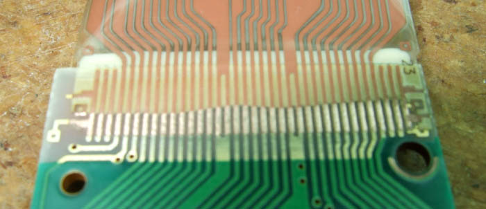
This might be a really odd question and/or horrible idea, but could I (realistically) solder an FPC cable meant for a connector directly to a PCB using hot air or a hot plate?
supple pollen
Some commercial devices are built that way, so I'm guessing it's possible, but I'm unsure what tools and techniques are used. One I'm familiar with is the Nintendo Virtual Boy https://www.projectvb.com/vb/tech/displayfix/beforesolder.jpg @grand wind
 humble swift
wasnt that cable notoriously dodgy
supple pollen
Heh, yup.
 onyx kernel
hey. im just wondering what VDDIO stands for? I have a ICM-20948 gytoscope with a VDD of 1.8-3.6v and a VDDIO of 1.71-1.95v. As i understand it VDDIO is for the in/outputs of the chip, does that include I2C? So would i need a 1.8v I2C bus? Also this is a project of mine which i started months ago and i just picked it up again and i seem to have designed it with nothing connected to VDDIO. But when testing it back then i connected the i2c to 3.3v so is it fryed?
supple pollen
It's the power supply for the I/O pins. Some chips offer separate power supplies for the core and I/O like that.
It can be useful if you want to have your I/O at a different voltage from the core
onyx kernel
so its most likely fried when i connect it to a 3.3v i2c bus (with VDDIO floating)
supple pollen
I don't think that would necessarily fry it. Presumably the protection diodes would conduct and drag up the VDDIO rail to 3.3V minus a protection diode drop.
 inner rampart
What's the feasibility of getting the original manufacturer of the 32x8 max7219 dot matrix displays to design one with an esp32 module onboard with a usb port. https://www.amazon.com/HiLetgo-MAX7219-Arduino-Microcontroller-Display/dp/B07FFV537V

HiLetgo MAX7219 Dot Matrix Module for Arduino Microcontroller 4 in 1 Display with 5pin Line
 left grove
sounds possible to do yourself 😝
supple pollen
It's easy enough to just hang an ESP32 board on one
inner rampart
true but I really want the entire device to be completely assembled by the PCB house.
woven bluff
can I replace this part of the ZVS with a LDO?

also, doesn't the primary need some kind of snubber?
left grove
inner rampart
true but I really want the entire device to be completely assembled by the PCB h...
you can totally get that done as well.
There are services that offer PCB+parts+assembly so you just send them the files and you get fully assembled PCBs.
I haven't made such things but I've seen people here and on other parts of the internet use them.
supple pollen
woven bluff
also, doesn't the primary need some kind of snubber?
No, the primary doesn't need a snubber because it's a resonant design: C1 and the primary form a tank circuit with a resonant frequency, and the transistors just keep it oscillating (like pushing a child on a swing).
woven bluff
humm, this is also the first time I try the non-center-tapped ZVS version.
Wouldn't it short this way?
 jade wedge
Not knowing exactly what this is, I suspect "shorting out" is largely the point. This looks like a design to take a DC power source and turn it into high frequency and (presumably) high voltage AC. Transformers of that design don't work with DC. If that is the case, it's less of a short than you might think as the load on secondary side of the transformer should create an inductive load on the primary side.
But, I could be talking out my butt here.
woven bluff
those two paths do not pass through primary
jade wedge
No, but they will influence it, and be influenced by it.
woven bluff
they just charge L1 and L2
supple pollen
The idea is that L1 and L2 have high enough inductance that they block the high frequency switching signal and just conduct the DC supply.
If you were to leave one of the transistors on, yes, high current would flow through an inductor and that transistor. But the transistors switch on and off alternately at a high frequency.
woven bluff
but they do not supply DC either
this two paths switch on and off the same time, and only one of them is useful
 supple pollen
What's going to happen is the nodes at the transformer ends of the inductors will end up with a DC potential of approximately VCC/2 with an AC waveform superimposed on it. So current will flow through the inductors as the power supply tries to pull that VCC/2 up to VCC, this is the power supply for the primary, and is what you want. The AC waveform will flow back and forth through the transformer primary and capacitor, propelled by the switching of the transistors.
As long as the switching frequency is high enough in relation to the inductance of the inductors, they'll block most of the AC.
In practice, the majority of the current does not flow along either of the paths you have marked.
woven bluff
so the primary will be charged by L1 and L2 mostly?
inner rampart
@left grove yes it sounds simple but once you actually try to do it many complications arise. Mostly part sourcing.
supple pollen
woven bluff
so the primary will be charged by L1 and L2 mostly?
Not really "charged", but voltage will flow in through L1 and L2 (mostly DC) and out through Q1 and Q2 (DC and AC). What the circuit is doing with this power is getting C1 to charge through the transformer's primary, then it discharges through the primary. All this activity basically gets current bouncing back and forth through the transformer's primary, which is of course the entire point of the thing.
rigid plume
Hi folks
I was wondering if this would work

I'm trying to create an high precision current source to do Deliver currents of up to a few amps with precision.
Allow dynamic adjustments at up to 10kHz.
Maintain a stable output at DC when necessary.
based upon

Thanks
supple pollen
I don't see a current output anywhere. Is this just the reference stage? It looks like a DC reference, so presumably you'd be doing your dynamic adjustments elsewhere? What sort of precision are you looking for?
rigid plume
supple pollen
I don't see a current output anywhere. Is this just the reference stage? It lo...
Well Im new to this and I need to precisely control the output voltage of the current source, which in turn determines the current delivered to our coils.
Around 5 m.v
supple pollen
Ah, you're driving an inductive load? At 10kHz, the voltage and the current are going to be out of phase...
5 million volts? At a few amps? So 20 megawatts or so?
supple pollen
Heh, yeah, I wondered. Big M is "mega", little m is "milli". Big difference.
rigid plume
Haha yeap
supple pollen
That voltage reference lashup should be more than precise enough, if it's built with appropriate techniques, components, and shielding.
rigid plume
Yeap but I think there could be an issue with current
I need to get it up to an amp and this IC would maybe provide 10ma max
supple pollen
Right. Turning voltage to current in a precise fashion is fairly complicated when it's significant current. And if you're driving an inductive load, it gets even tougher.
supple pollen
It reminds me of the amplifiers driving a magnetically deflected vector display. Since the current through the deflection coils determines the position of the beam on the screen, it has to vary quickly and precisely. While there are power op-amps with more current capability, most of them aren't made any more. The usual approach these days is to have an op-amp driving a power transistor, with a current sensing resistor in the load, which completes the feedback loop of the op-amp. Then the op-amp takes care of dealing with a lot of the deviations from linearity.
rigid plume
I see 😅 that is a bit complicated do you have any pdfs I can research on or perhaps ref schems
I'm trying to make this board as quick as possible haha
supple pollen
If you search for the Vectrex service manual (it's available as a PDF), you can see the schematics of its deflection system (based on LM379 op-amps).
 supple pollen
This page includes a some useful info on the subject https://tubetime.us/index.php/2015/06/27/crt-magnetic-deflection-driver-design/
Including a link to a github with the design files
Based on LM4765 power op-amps capable of driving almost 3 amps into a load
Linear Technology offers this useful application note on boosting op-amp outputs https://www.analog.com/media/en/technical-documentation/application-notes/an18f.pdf
Including an amazing ±120V output stage that uses 12BH7A vacuum tubes!
 sweet cairn
I've implemented the PAM8302A audio amp chip in my design using Adafruit's version as a reference. Can someone please tell me if I've made any mistakes on the hardware side?
My design

Adafruit's design

My schematic

Adafruit's

Previously I've been told that the schematic itself is fine, but I was wondering if there is something else that I'm missing. I've got a testrun of my board and it isn't working so trying to eliminate all possible faults
The datasheet for the chip: https://www.diodes.com/assets/Datasheets/PAM8302A.pdf
One change I've made over adafruit's design is to use tantalum caps instead of mlcc ones.
supple pollen
Polarized capacitors for coupling capacitors might cause issues, I'm not sure. Do you have an oscilloscope?
When you say it "isn't working", what do you mean? What color flames do you get?
sweet cairn
supple pollen
Polarized capacitors for coupling capacitors might cause issues, I'm not sure. ...
Yes I can access an oscilloscope although I don't really know how to use one
sweet cairn
supple pollen
When you say it "isn't working", what do you mean? What color flames do you get...
I'm not getting audio output.
Someone tested the firmware I'm using on the Adafruit PAM8302A board and the same set of daughterboard pins that I'm using and it's working for them (though I think they used a different buzzer)
sweet cairn
supple pollen
When you say it "isn't working", what do you mean? What color flames do you get...
'flames'? What is that? What do you mean?
supple pollen
One of the worst failure modes is flames shooting out of components 
supple pollen
It could be your "buzzer" doesn't have enough inductance
supple pollen
Hook it to an ordinary speaker
sweet cairn
I have access to an oscilloscope and a multimeter
sweet cairn
supple pollen
Hook it to an ordinary speaker
Hmmm that I don't have rn unfortunately 😅
sweet cairn
supple pollen
It could be your "buzzer" doesn't have enough inductance
Also if this is indeed the issue, then what's the solution?
sweet cairn
sweet cairn
I'm not getting audio output.
Btw when I say this, I mean that I get zero output at all. Not even static or crackles or anything, anything that was audible to me at least
supple pollen
I'd see if the supply pin has voltage and the ground pin doesn't. Then I'd look for PWM on the output leads with an oscilloscope
sweet cairn
supple pollen
I'd see if the supply pin has voltage and the ground pin doesn't. Then I'd look...
So this is the supply pins and GND pins of all components while the device is in operation, correct?
Is that safe to do with capacitors?
sweet cairn
supple pollen
I'd see if the supply pin has voltage and the ground pin doesn't. Then I'd look...
Output leads of the IC right?
woven bluff
supple pollen
One of the worst failure modes is flames shooting out of components <:sparky:342...
wait until you see a high current diode explode, I couldn't hear anything for 5 minutes
quartz flume
I have 8000mAh in parallel same-capacity batteries connected to a Powerboost 1000 Basic. I need a way to power them that won't take 20 hours, and I need to make sure I can power them while they're connected. Any advice?
rigid plume
Hi folks I was wondering if this DAC circuit will work?

just needs to precisely control the output voltage of the current source
supple pollen
quartz flume
I have 8000mAh in parallel same-capacity batteries connected to a Powerboost 100...
Do you mean charge them? There are chargers that deliver (or can be configured to deliver) more than 500mA. Do you mean charge them while they're powering something? That is somewhat more difficult.
supple pollen
rigid plume
Hi folks I was wondering if this DAC circuit will work?
That will basically work, giving about 20mV resolution with a 5V supply. Note that R6 and R7 form a voltage divider, so the output will be from 0-2.5V. Note that op-amp isn't specified for rail-to-rail input, so it may behave strangely at low output voltages.
 crystal nova
Not sure if there is a better place to ask, sorta hw design.
Does anybody have any recommendations for mounting a small solar panel (~4in x 5in) to a wall. Something cheap or DIY would be preferred vs a $20 or $30 solution per panel.
supple pollen
Nails? Double sided tape? Is this indoors or outdoors? Is this a bare panel or an enclosed one?
crystal nova
outdoor, bare panel
supple pollen
Presumably you'd want to add some sort of protection. Maybe sandwich the panel between a couple of sheets of glass or plastic that extend past the edges of the cell and use those to mount it?
crystal nova
Interesting thought
humble swift
You can get exterior mounting tape that might do it, depends on if you think the panel will be fine uncovered
wispy blade
should i be using a schottky, zener, or rectifier diode for preventing reverse voltage/polarity when connecting to an unknown power source?
my intuition wants to use a rectifier/silicon diode but thats really the only thing ive learned about
supple pollen
An ordinary rectifier will work, but will incur a voltage drop (about 0.6V for ordinary silicon diodes). The advantage of a Schottky diode is a lower voltage drop. A zener diode has the ability to conduct in the reverse direction at a specified voltage, it's not particularly useful as a series polarity protection diode (but they're popular as a parallel polarity protection diode as they protect against both overvoltage and reverse voltage, but you'll want current flow protection such as a fuse if you're employing a parallel polarity protection scheme).
wispy blade
supple pollen
An ordinary rectifier will work, but will incur a voltage drop (about 0.6V for o...
so i assume ill want a schottky for carrying 3.3v to something like a microprocessor to reduce voltage drop
wispy blade
also dunno if this belongs here, but if anyone here is experienced in kicad, is there any way i can have two busses which share pin/wire names? (the pcb wants to tie j1's pin 5 directly to gpio12)
 supple pollen
wispy blade
so i assume ill want a schottky for carrying 3.3v to something like a microproce...
supple pollen
wispy blade
so i assume ill want a schottky for carrying 3.3v to something like a microproce...
Yes, Schottky or an ideal diode for that use case
wispy blade
great, thanks again!
 supple dagger
is this qty two 2.2uf caps in series?
 rigid plume
supple pollen
That will basically work, giving about 20mV resolution with a 5V supply. Note t...
rigid plume
supple pollen
That will basically work, giving about 20mV resolution with a 5V supply. Note t...
Thank you very much our application isn't too critical
Another question if you can look at :), is this the correct way to get - voltage
 rigid plume
supple dagger
is this qty two 2.2uf caps in series?
rigid plume
supple dagger
is this qty two 2.2uf caps in series?
yeap
supple pollen
supple dagger
is this qty two 2.2uf caps in series?
Or parallel
supple pollen
rigid plume
Another question if you can look at :), is this the correct way to get - voltage
I'm having trouble reading the IC name at that resolution. But it looks like you have a missing diode and a 0Ω resistor shorting the -15V signal to ground.
jade wedge
I kinda wish TI's power designer would just say if those capacitor pairs should be series or parallel.
pale umbra
Can someone please remind me of the big chinese parts seller, dont remember if it's taiwan/hong kong/china but they seem to have everything and I think they make an app to make a circuit from which you can order parts as well. I always forget it but they sell low-grade parts that digikey/etc wont even make available and I found a mcu that sells for like 1 us$ and Im curious
supple pollen
jade wedge
I kinda wish TI's power designer would just *say* if those capacitor pairs shoul...
I strongly suspect parallel (to increase capacitance and lower inductance and ESR). https://e2e.ti.com/support/power-management-group/power-management/f/power-management-forum/654554/webench-tools-tps61021a-webench-tool-query-cout-cap-is-showing-quantity-3-what-does-it-mean
Series would halve the capacitance and double the ESR and inductance.
If you click on the part, you should be able to get to an "alternate part selection" dialog where it gives the calculated limits on capacitance, ESR, ripple current, etc. You can switch parts or use the parameters to look for other possibilities.
rigid plume
supple pollen
I'm having trouble reading the IC name at that resolution. But it looks like yo...
On the ti webench it shows it being connected to gnd and there wasn't a diode on webench ic is lm25088mh
rigid plume
pale umbra
Can someone please remind me of the big chinese parts seller, dont remember if i...
If you do find it please tell me, it sounds interesting
supple pollen
rigid plume
On the ti webench it shows it being connected to gnd and there wasn't a diode on...
Ah, okay, that chip uses a different circuit configuration, so you're fine on the diode. I'm going to assume R16 is 16 milliohms (16mΩ) instead of 16 megaohms (16MΩ). However, R20 still seems problematic, as it's shown as zero ohms and connected from the "-15V" node to ground, which would be a short circuit.
supple pollen
pale umbra
Can someone please remind me of the big chinese parts seller, dont remember if i...
The usual Asian parts supplier I see is LCSC, but I don't know anything about an app.
jade wedge
supple pollen
I strongly suspect parallel (to increase capacitance and lower inductance and ES...
Ah, that makes sense. The larger capacitince alone would make more sense from what I know about buck/boost power circuits. You want to ensure a smooth supply.
pale umbra
supple pollen
The usual Asian parts supplier I see is LCSC, but I don't know anything about an...
yeah it was LCSC but they dont have any phyplus PHY6222 microcontroller on an eval board. I guess my only bet would be to buy a fake 2$ "smart watch" with it maybe in it. oh well i give up. It was a low power 3.3V ble chip with nice specs so I wanted to try it but the datasheet is only 46 pages so I guess I would have been on my own a lot. Seems well supported (in chinese) but I cant find anywhere to buy it.
 golden wasp
Hi, I'm building a project based on the Adafruit Feather ESP32 V2. It seems that I'll be needing 12V to drive some LEDs and I plan to use some small stepper motors to rotate some dials to display things. I'd use the USB port only to upload code and debug, during normal operations no USB is needed. Is it a good approach to use a small 12V DC wall adapter and then have a circuit that converts the voltage to 5V and hook that 5V up on the USB and ground pins of the Feather? What would you use for this? A buck converter?
wispy blade
golden wasp
Hi, I'm building a project based on the Adafruit Feather ESP32 V2. It seems that...
what you're looking for seems to be a voltage regulator. not that im very experienced but i think a buck converter is a subcategory of voltage regulators, or would serve the same purpose as one
pale umbra
golden wasp
Hi, I'm building a project based on the Adafruit Feather ESP32 V2. It seems that...
can you give some more details on the led / why they are 12V ?
I feel like if I suggest getting a led driver chip you'll probably say you already have one and that this mght be a led array. Right ?
golden wasp
I have pushbuttons with LED-s and it says that you have too hook them up on 12V.
I don't have a dedicated LED controller, I'd just use the PWM pins of the ESP32
I haven't calculated yet how many pins I need but I see that it's easy to run out of pins fast.

 woven bluff
can something like this work as UVLO?

when your board only has one IC, and the IC only has one GND pin, is star grounding still a thing?
quartz flume
supple pollen
Do you mean charge them? There are chargers that deliver (or can be configured ...
That is what I meant, I apologize. I think what I'm going to do is design a PCB for it. Found a nice little chip that allows for 4 batteries in series to be charged through PD while also powering something. Automatically detects battery voltage as well 🙂
woven bluff
quartz flume
I have 8000mAh in parallel same-capacity batteries connected to a Powerboost 100...
5V charger's are limited to 2A, so it will take at least 8 hours or so to fully charge it depending on charge curve. Any faster you will need PD. Most modern charger chip have load sharing (some even have back-boost function you won't even need a boost regulator) so you can power. If you want pre-made boards I'm not aware any of those can meet your demand.
also any chip with high power and advanced functions are likely only FN or BGA packaged. It will be steep if you have never designed PCB before.
quartz flume
I'm gonna just an MP2760 chip for it 🙂
Should work well. Buck output down to 5V and run into my components
woven bluff
I don't think that one has PD negotiation so you will also need to program a MCU to control it.
woven bluff
I tested the cheap mmWav radar HLK-LD2410. It's much better than PIR, but eats tons of power...
 alpine zephyr
Hey folks. I'm having a problem that I don't know how to troubleshoot, so I figured I'd ask here. I'm doing a project with a pyportal which I need to power off a battery. I followed the guide linked below to power the pyportal off of a lipo. I've tried connecting both a battery, a microusb cable, and both to power the pyportal and the same thing happens: the unit starts, and my program appears to load, because it renders my interface, but hangs there. When I power through USB, it works perfectly, but through stemma, it doesn't connect to WiFi and get going. Any thoughts on what might be going on? I can't plug into the computers USB to read the output, because then I'm not powering off the battery charger!
 supple pollen
alpine zephyr
Hey folks. I'm having a problem that I don't know how to troubleshoot, so I figu...
supple pollen
alpine zephyr
Hey folks. I'm having a problem that I don't know how to troubleshoot, so I figu...
I've seen that sometimes when the program tries to send or receive something over the (USB) serial port, and hangs if the USB isn't connected.
alpine zephyr
Ooooh so removing print statements could do it?
supple pollen
golden wasp
I haven't calculated yet how many pins I need but I see that it's easy to run ou...
If you don't need to change color, you can save pins. You can also use external driver chips to power the LEDs.
supple pollen
alpine zephyr
Ooooh so removing print statements could do it?
Yes, along with any serial initialization statements
alpine zephyr
Ok. Thank you so much I'll try this
alpine zephyr
supple pollen
I've seen that sometimes when the program tries to send or receive something ove...
So I tried this, and I think it's on the right track, but how do I prevent any serial communication with CircuitPython? Like is there a command i can run at the top of my program to cut the serial connection? I ask because libraries I'm using, like for wifi, include print statements for connection failures, etc, and I want to suppress those as well.
alpine zephyr
Ach this is not the right channel for that question, sorry! Moving to the help with CP channel
 dry pelican
supple pollen
I strongly suspect parallel (to increase capacitance and lower inductance and ES...
dry pelican
supple pollen
I strongly suspect parallel (to increase capacitance and lower inductance and ES...
almost definitely. I've seen a buck converter blow up because 2 22uF caps in series were substituted for a 10uF
never forget your decoupling 
pale umbra
anything else to know ? I thought this was the point of buying an IC to do it that they would take care of everything especially ti/analog devices...
supple pollen
ICs can do a lot, but switching power supplies are tricky things, and while the ICs and design software can corral some of the quirks, there's still need for some domain knowledge to implement one successfully. It's not quite like the simplicity of 3-terminal linear regulators, where they have almost everything baked in for you (but they too can do nutty things with the wrong input or output capacitor setup in some circumstances).
You can buy packaged switching power supply modules that abstract even more of the design for you. Personally, I'm quite fond of them, as they often contain optimizations (like custom designed magnetic components) that are impractical for me to employ.
cursive sentinel
Yeah, switching regulators rely pretty heavily on the external passive components. Physics doesn't allow us to build good inductors or capacitors on a chip.
knotty tiger
at least not at power levels that are useful for most applications…
pale umbra
It's just that I expected buck-down to be plug and play. I hope the datasheet would say I needed caps for it or anything else I need for it. Oh well
supple pollen
The data sheet should specify that in detail. Most manufacturers also offer application notes that explain things more thoroughly
cursive sentinel
knotty tiger
at least not at power levels that are useful for most applications…
Internal charge pumps are commonplace.
knotty tiger
chip-scale inductors are harder than capacitors, but they do exist
supple pollen
I suppose it depends on which parameters you need, but in general, yes, they're a distinctly inferior substitute
knotty tiger
on-chip charge pumps for EEPROM/Flash programming are commonplace, but tend to only use switched capacitors instead of inductors
cursive sentinel
Indeed
(side note: charge pump implies the use of capacitors rather than inductors)
pale umbra
is there something like a digital galvanometer chip that would replace an analog one with the big needle and display to use with an LCD instead of having an imprecise needle/ink analog meter? Did a search on digikey but there dont seem to be any (or it's called something else)
knotty tiger
like with a normal graphic LCD, or one with custom patterns?
pale umbra
with a normal graphic LCD to display the value. This would be for an esr meter and Im hoping to have more precision between 0 and 2 ohms that looking visually
ie: trying to have a better measurement in the zone circled than trying to determine visually where it is between 0 and 2
 knotty tiger
when driving a normal graphic LCD, there’s usually a microcontroller involved. i’m not aware of any special purpose analog meter emulation chip. you can get stuff like LED bar graph driver chips, but they have less precision than what you want
pale umbra
yeah I was trying to find a digital galvanometer chip that would basically convert the analog measurement to a digital one with an ADC in it so I could read it from a microcontroller and display it. But it seems I would have to get a different schematic completely. Anyway question 2) Youtuber is saying to make sure the resistors are high precision(0.1%) and from the same batch. I'm not sure how to make sure of that when ordering from say digikey and when there are many resistors to get:
 dry pelican
I don't think same batch will matter that much (I think the youtuber is saying that because maybe the same batch resistors will have similar tempcos and drift the same amount). Precision definitely does matter though. Also, if you order from digikey, they should give you resistors from the same batch since they will come from the same reel
knotty tiger
you can also buy more than you need, and hand-match using a high-precision multimeter
you still want to buy the high-precision stuff, because they tend to be more stable in terms of tempcos, etc
pale umbra
would brands matter here ? From what I can tell most digkey stuff seems to be middle-end at least they dont really sell really cheap random brands.
and I dont need that many resistors for this so might be worth going for quality over quantity since it's for a measure instrument
 uncut briar
Hello, I am designing a board with the rp2040. I am following this doc: https://datasheets.raspberrypi.com/rp2040/hardware-design-with-rp2040.pdf#page9
In the schematic it shows a 100nF cap at the VCC pin for the flash device, but the device I picked has no indication, from the datasheet, that the capacitor is needed. Is this capacitor required anyway?
pale umbra
But they explained 1 page before that such things are decoupling capacitors and must be as close to the power source as before and the diagram looks exactly the same as the page before it. They probably didnt mention it again for brevity
As per the rules from 2.1.2 flash has one power pin so one 100 nF cap ("Because, of this, it is important to place decoupling close to the power pins. Ordinarily, we recommend the use of a 100nF capacitor per power pin")
uncut briar
pale umbra
As per the rules from 2.1.2 flash has one power pin so one 100 nF cap ("Because,...
Yeah, but I think that is referring to the power pins in the rp2040 chip, no?
pale umbra
It's a rule normally for anything that has a power pin to have decoupling because no power supply is perfect unless a datasheet says otherwise
and to put it as close to the power source as possible
See mostly 2nd paragraph
 supple pollen
pale umbra
yeah I was trying to find a digital galvanometer chip that would basically conve...
supple pollen
pale umbra
yeah I was trying to find a digital galvanometer chip that would basically conve...
I suspect that youtuber is talking through their hat. While such precision resistors exist, they're not cheap (except from surplus vendors where you can sometimes get them at competitive prices, but you don't get a choice of value) and rarely actually needed.
pale umbra
or I got confused with 1% 😄
I'm trying to do the esr meter from QNZ magazine from AARL april 2014 to test caps
supple pollen
Measuring ESR is a fairly approximate venture anyway, but 1% resistors are cheap and common and generally more than good enough.
pale umbra
art of electronics 3rd edition dont even say why for the 100 nf decoupling caps...
while the quote from above is from my practical electronics for inventors
 distant raven
I tend to see that 100nF is a common value because it can get you in a rough order of magnitude of closeness to effective decoupling values. This usually ends up being more evident in designs where you see them paired with 10,4.7,2.2, and 1 uF capacitors
There was a video I watched some time ago that demonstrated this, but I can’t find it for the life of me
pale umbra
supple pollen
I suspect that youtuber is talking through their hat. While such precision resi...
nah they really said either resistors from the same batch or uses 1% (around 0.15$ for each from a good brand like panasonic for throught-hole) or 0.1% (around 0.75$ each for throught-hole)
distant raven
But basically it comes down to effectiveness on managing transients and cost
100nF are ridiculously cheap and generally take up very little space
pale umbra
also that circuit uses both AC and DC, I finally get to play with AC lol
distant raven
Also using a bunch of 100nF in close proximity can sometimes help with DC derating in a smaller footprint than larger packages of similar value. But there is a big caveat to that derating claim as well
If you can do big packages, don’t hesitate
Some people I follow have found the best space to derating ratio is found between 0805 and 1206 MLCC
supple pollen
The derating depends on the dielectric, which in turn depends on the capacitance and volume. The upshot of that is, you can get less derating for the same footprint with a taller package.
 wide patio

Many designs today include three different value decoupling capacitors, or when using just one capacitor, a small value like 0.1 uF. These recommendations are based on 50-year-old assumptions that do not apply today. It is time to reconsider these out of date, legacy design guidelines.
supple pollen
Oh, I was looking for that article a while back! I really like its treatment of the subject matter.
woven bluff
I have never seen this in datasheets or application notes, only in schematics made by hobbyist.
onyx kernel
Hey i could use some help designing a pcb with an RF Antenna. Im taking this Picocklick C3 as a reference and im wondering why the FEED line gets connected to GND at the antenna. also when i use the same antenna in EasyEDA it only has two pads, the one for the FEED line and the so called Soldering terminal (which isn't connected to anything) But there is no GND Pad besides the FEED line.
The antenna im using: KH-RFECA3216060A1T_V09 (C411566 on LCSC)
This is the Picoclick (my reference) https://makermoekoe.gitbook.io/picoclick-c3/hardware
The first pic is the PCB of the Picoklick the secone one is the antenna on my PCB


 supple pollen
onyx kernel
Hey i could use some help designing a pcb with an RF Antenna. Im taking this Pic...
supple pollen
onyx kernel
Hey i could use some help designing a pcb with an RF Antenna. Im taking this Pic...
I don't see where the feed line is connected to ground, so I'm a little lost
onyx kernel
its "not" connected on the gerber file/footprint but the antenna only has one solder pad on each side so you "short" the feedline to gnd when soldering it on
supple pollen
According to the data sheet, one terminal is the antenna connection, and the other is just for mechanical stability (not connected)
onyx kernel
supple pollen
According to the data sheet, one terminal is the antenna connection, and the oth...
yes thats how ive done it. give me a sec ill try to find a pic of how the same antenna is soldered to the picoclick
supple pollen
Oh, I think I see what you're referring to: a single pad bridges from the feed point to the adjacent ground



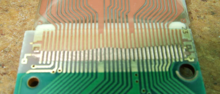 supple pollen
I'd expect something more like this

It's like the first part of the data sheet doesn't agree with the second part
onyx kernel
on a nother note how bad is this rf setup? i know its horrible, but i don't have much space and i don't need a huge range. There is 2 layers of GND between top and bottom
 unique patio
onyx kernel
on a nother note how bad is this rf setup? i know its horrible, but i don't have...
unique patio
onyx kernel
on a nother note how bad is this rf setup? i know its horrible, but i don't have...
do you mean there is a trace antenna there? The keepout area for a trace antenna should not have ground planes underneath
or same for chip antenna: https://www.lairdconnect.com/resources/white-papers/how-to-implement-chip-antennas
onyx kernel
Wrong wording... its everywhere but under the antenna
 unique patio
is it a chip antenna? The mfr will have guidelines
onyx kernel
but there is virtually none clearance between the antenna and the rest and also the feed line is not optimal. I know the guidelines but how bad is it to not follow them.
unique patio
the guidelines are for Reasons. If you don't follow them you can compromise the performance of the antenna, and also maybe allow RF to get into your own circuitry
I'd suggest that you start with the guidelines as an absolute, and redo the layout around it.
without being an expert or experienced you can't know what will work and what won't
onyx kernel
Version 5.0 of the pcb🥹 nah joking desinging pcbs is fun 🙂 Thanks
unique patio
good luck!
onyx kernel
ty
rigid plume
Hi folks I have a question on my schem design

This is supposed to get the 10v output from an precise voltage output source (100ma) and boost it to 1A
Does this look like it will work?
based on
 unique patio
if you are using a design program all the points with the same name will get tied together. I don't think that's what you mean here (all the "+10V")
rigid plume
unique patio
if you are using a design program all the points with the same name will get tie...
yes Im just using it as an example
unique patio
how precise is precise? Why not just use a 10V 1A regulator?
note the caveat in the text you posted
pointing to 4.26
rigid plume
unique patio
how precise is precise? Why not just use a 10V 1A regulator?
it's supposed to be for an magnetic field tuning system
unique patio
is it supposed to be 10.0000 V, or is supposd to be very stable?
stability is important for both, but just stable is different than stable and precise
rigid plume
well I just need it to be precise within a few 100 mV at most
and it does have to be stable but not as stable
there is room for the stableness
unique patio
how is the field tuned? Are you varying the voltage or something else?
I am no expert on this, but it sounds like you just want a well-regulated power supply
rigid plume
dynamic adjustments at up to 10kHz.
rigid plume
unique patio
I am no expert on this, but it sounds like you just want a well-regulated power ...
well it needs to be very precise and I can't find solutions that are to deliver upto an 1A
unique patio
so are you varying the 10V to tune, or something else
rigid plume
yes to tune
 unique patio
you mean the specs on various voltage regulators are not stable enough?
rigid plume
i mean they are not as precise
rigid plume
I see
supple pollen
It seems like what you want is a voltage to current converter. The op-amp configuration you show isn't going to do that, but it's similar to what I was telling you about earlier, with a boost transistor and a current sensing resistor in an op-amp's feedback loop.
unique patio
over to you @supple pollen I did not see the previous discussion
rigid plume
Thanks
 hollow cosmos
Is there a way to control the Trinket via Bluetooth in near real time, bi-directionally?
How about with USB?
rigid plume
supple pollen
It seems like what you want is a voltage to current converter. The op-amp confi...
Well I was just looking to boost the output current of the precision votlage circuit
supple pollen
Yes, that is a voltage to voltage converter with an output capable of sourcing a fair amount of current, but my understanding is that you wanted to regulate the current, not the voltage.
supple pollen
hollow cosmos
Is there a way to control the Trinket via Bluetooth in near real time, bi-direct...
It's easy enough with USB, I don't know about Bluetooth
TI offers this nice writeup on a converter that uses a 0-10V input to program a current from 0-1A https://www.ti.com/lit/an/sboa325/sboa325.pdf
hollow cosmos
supple pollen
It's easy enough with USB, I don't know about Bluetooth
From an iPhone to the Trinket?
rigid plume
supple pollen
TI offers this nice writeup on a converter that uses a 0-10V input to program a ...
Thank you very much I will look into it
supple pollen
If you want to control it with an iPhone, you would presumably have some sort of software on the iPhone to do the controlling.
unique patio
hollow cosmos
From an iPhone to the Trinket?
not a Trinket, but the nRF boards we have can talk Bluetooth to the iPhone. You could use the Bluefruit Connect app
any particular reason it should be a Trinket?
supple pollen
rigid plume
Thank you very much I will look into it
Here's a beefier version capable of 5 amperes https://www.ti.com/tool/CIRCUIT060047
hollow cosmos
unique patio
any particular reason it should be a Trinket?
I have 4 solenoids to control from the iPhone (which the Trinket can do with its 4 PWM outputs), just a “set solenoid #3 to push” message. Plus, I need to send info back to the phone about overheating, jams, and other status. Bluetooth seems like overkill.
USB gives me Trinket power too (I still need 4a to power the solenoids, from batteries or wall adaptor), but when I connect the Trinket to the phone, the Trinket’s power lights don’t illuminate, so I figure the USB drivers are not recognized.
The Trinket doesn’t power on from the phone.
rigid plume
thanks
unique patio
hollow cosmos
I have 4 solenoids to control from the iPhone (which the Trinket can do with its...
USB devices say how much power they want. The Trinket may be asking for more than the iPhone wants to supply
what kind of Trinket?
classic or M0?
3.3V or 5V classic?
hollow cosmos
unique patio
USB devices say how much power they want. The Trinket may be asking for more tha...
M0 3.3v
unique patio
hollow cosmos
M0 3.3v
what kind of dongle are you using on the iPhone?
hollow cosmos
It was just a standard lightning to USB type A, then a short female A to the micro B adaptor. Do you think it’s the cabling?
Is the USB host supposed to send out a trickle charge to activate the Trinket’s USB signature return?
unique patio
 unique patio
hollow cosmos
It was just a standard lightning to USB type A, then a short female A to the mic...
unique patio
hollow cosmos
It was just a standard lightning to USB type A, then a short female A to the mic...
you need an OTG thingie to make the Trinket visible as a device. Above, an Apple Lightning to USB camera adapter, connected to a Trinket M0, which is lit up. Phone is showing contents of CIRCUITPY drive
i don't think the iPhone is going to pass USB CDC serial. Its USB connectivity is very limited, for security and marketing reasons
we normally do all this kind of stuff with BLE
hollow cosmos
unique patio
you need an OTG thingie to make the Trinket visible as a device. Above, an Apple...
Is the Trinket’s BLE fast and reliable?
unique patio
the Trinket has no BLE. You need something like a Feather nRF52840 or Itsy Bitsy nRF52840
The CircuitPython support on ESP32-S3 for BLE is very limited right now. Arduino is possible, but I haven't tried it
CircuitPython BLE projects https://learn.adafruit.com/adafruit-circuit-playground-bluefruit/getting-started-with-ble-and-circuitpython
https://www.adafruit.com/product/3093 might be interesting

Sometimes we wonder if robotics engineers ever watch movies. If they did, they'd know that making robots into servants always ends up in a robot rebellion. Why even go down that path? ...
don't your solenoids need motor drivers or external transistors?
hollow cosmos
unique patio
the Trinket has no BLE. You need something like a Feather nRF52840 or Itsy Bitsy...
If I understand the question, these solenoids have internal springs so there’s no “reverse” direction to energize. I was also looking into latching solenoids that only expend energy when changing states.
A motor driver would be, for example, an H drive, that allows for reversing the direction of travel?
unique patio
i just mean a high-current driver of some kind here. The CRICKIT has that on board
sorry, I didn't really mean motor driver
hollow cosmos
At 1 amp, I’ll need something heftier, like a TIP120.
Can I drive 4 amps with a cricket and no external transistors?
unique patio
- 2 x Bi-directional brushed DC motor control, 1 Amp current limited each, with 8-bit PWM speed control (or one stepper)
- 4 x High current "Darlington" 500mA drive outputs with kick-back diode protection. For solenoids, relays, large LEDs, or one uni-polar stepper
no
so the CRICKIT doesn't solve your problem
https://www.adafruit.com/product/5757 but only 2.5A max
Looking for a small compact board to power up your high current relays, solenoids or LEDs? Well, look no further this new 4 channel Mosfetti by Monk Makes board is just what you need for ...
Sparky the Blue Smoke Monster shows up whenever the magic smoke is let out of an electronic component. And his very favorite is whenever folks first start with electronics and robotics: ...
hollow cosmos
That was what I was thinking. Even the 8-way Darlington chip maxes out around 1.6 amps across all circuits, due to heat dissipation issues.
unique patio
5648 is hefty enough, you need four. Or just wire up your own. Don't forget kickback diode because they are inductive loads
what do these solenoids control, door latches or something?
hollow cosmos
They move tiny “bumpers” to divert tiny cardboard pieces (0.5 grams) moving down a chute into the appropriate bin. Adafruit is out of the mini ones, so I’m trying out the next size (which is marked as “small”).
unique patio
would servos work? Less power consumption
hollow cosmos
I’m also looking into this new device called a “flap actuator” that is a coil on a paddle that attacks or repels a magnet.
unique patio
you can convert a servo rotary movement into a linear movement with the right linkage
not sure it's fast enough for you
hollow cosmos
Servos would work, but they require power to keep a position, right? A latching solenoid only uses power to switch positions.
Speed is accomplished by a lever.
unique patio
hollow cosmos
Servos would work, but they require power to keep a position, right? A latching...
they use a lot less power, and the gearing mostly keeps them in place. If they get displaced, then the motor runs. tiny cardboard pieces are not going to move the positions
solenoids and stepper motors are very powr hungry
hollow cosmos
Is there a better tech that I’m missing? (Besides the flat actuators?)
unique patio
there are linear servos ("linear actuators")
hollow cosmos
The linear servos I found were really slow. I think they were built for precision rather than speed.
unique patio
i don't completely understand the use case. pieces of cardboard are going down a chute? you want to sort them into multiple paths?
hollow cosmos
Yes, multiple paths. Like a coin sorter.
unique patio
so a regular servo could move a paddle to the left or right to choose a path. Any friends who are mechanical engineers?
hollow cosmos
Hey, that’s a great idea. With a single servo I could choose between 4 paths instead of using 3 solenoids, if I could get a fast one.
unique patio
there are various servo coin sorter projects; haven't found the perfect example in a websearch yet, but you could keep looking
hollow cosmos
And with a fifth position, I could block the path totally so the camera has a chance to image the piece (which is what determines which path it takes). That replaces ALL the other parts with a single servo! Brill!
unique patio
here's a project I didn't even know we had: https://learn.adafruit.com/machine-learning-with-marshmallows-and-tiny-sorter
not same mechanics, but uses a servo
arduino or CircuitPython for you?
hollow cosmos
That’s amazingly similar! Anduino seems overly complicated, and appears to have so many bugs. Is it worth it?
unique patio
CircuitPython is easier if you are not already a C/C++ programmer or familiar with Arduino. https://learn.adafruit.com/search?q=servo%2520circuitpython projects with servos
i will leave you to do some reading and cogitating
#help-with-circuitpython if you have CircuitPython questions
hollow cosmos
Even with the most advanced IDEs — and I’ve used them all — I still like editing a python file and using print() statements.
unique patio
#help-with-projects is more about projects like this. This channel #help-with-hw-design is more about circuit design
and PCB's, etc.
hollow cosmos
Thanks so much! Very helpful. You’re employed by adafruit, I suppose?
unique patio
yes
hollow cosmos
One bit of feedback I have for the company is how hard it is to find info on the website. I must have read 100 pages before I found out what “Express” means, for example, or what Cricket stands for. Or that I could find out what a board does by searching “Introducing …”. It’s so overwhelming that I feel you are losing sales.
A glossary would be more helpful than a search result — a glossary tells people what is possible to search for, that is, what topics are considered interesting.
unique patio
Yes, you have to bounce back and forth between the product descriptions in the shop and the product guides on https://learn.adafruit.com. We've tried various top-level guides in the past, but they're very hard to keep up to date. I agree it's overwhelming. But the idea of a glossary is interesting. I will bring it up internally.
hollow cosmos
I think you go around the room and ask each person for a list of 10 things they’d like customers to know about the website. Then combine them and add organization.
As for keeping it up to date, leverage the tags (look for patterns), saved pages, and the users. Add a “nominate this page” and have users type a reason to promote it to the glossary. DYI folk are willing to help out — your audience is unique, I think.
unique patio
✔️
sweet cairn
Hi I'm trying to replicate Adafruit's PAM8302A in my own design but it isn't working. I've already asked help about it here but narrowing down the cause of the issue is tough 😅
This is Adafruit's PCB

And this is mine

One big change compared to the Adafruit board is that I'm using polarized tantalum caps. There was a suspicion that that might be the issue. However according to the datasheet I should be fine, I have the polarities correct I think
A change/mistake I did notice though, is that pins 1 and 3 on my input trimpot are interchanged
So on Adafruit's design, the trimpot pin 1 is audio - and pin 3 is audio +
On my design pin 1 is audio/audio+ and pin 3 is GND (the audio - pin has to be tied to GND if it's not being used which is what I've done wherever audio - is used)
Idk exactly how trimpots work, especially with audio, so is this interchanging a reason why it may not be working?
supple pollen
Probably not: that would just make the adjustment "go the other way"
dry pelican
sweet cairn
Hi I'm trying to replicate Adafruit's PAM8302A in my own design but it isn't wor...
do you have a multimeter (or even better an oscilloscope)?
woven bluff
are there single-row led matrices?
left grove
woven bluff
are there single-row led matrices?
Isn't that just a Neopixel/WS2812B strip?
(or led strip in general)
The electrical matrix how it's wired doesn't really have to be the same as how it's physically laid out. Like you could but 4 LEDs in a line but wire them like a 2x2 matrix
supple pollen
woven bluff
are there single-row led matrices?
Basically a bunch of LEDs with a common anode or a common cathode? Yes.
unique patio
woven bluff
are there single-row led matrices?
Adafruit Industries, Unique & fun DIY electronics and kits : Search Results - Tools Gift Certificates Arduino Cables Sensors LEDs Books Breakout Boards Power EL Wire/Tape/Panel Components & Parts LCDs & Displays Wearables Prototyping Raspberry Pi Wireless Young Engineers 3D printing NeoPixels Kits & Projects Robotics & CNC Accessories Cosplay/Co...
 modest grail
in eagle is there a way to add a reference picture?
woven bluff
unique patio
See https://www.adafruit.com/search?q=led+bar
humm, I'm making a light printer, but those bars are too wide. I'm looking for something with smaller aspect ratio
supple pollen
I don't know what a light printer is, but there are lots of options.
woven bluff
supple pollen
I don't know what a light printer is, but there are lots of options.
it's a display device using your brain as buffer to store vertical line scans.
supple pollen
Ah, like a VirtualBoy. I've seen 1x1024 arrays on chips, as well as the ones in LED printers that are similar.
woven bluff
back in the day I got my first date by making one of those on a 8051 chip...
now I'm in a similar situation and I think such device may come in handy again.
supple pollen
Here's one vendor's description https://www.prpopto.com/wp-content/uploads/2018/08/Monolithic-LED-Arrays-Technology-Overview-20160616.pdf
For a cheap and easy to obtain option, you could use an OLED display and just light one line. An SPI interface one should be able to update fast enough.
woven bluff
actually, I don't need that kind of resolution, the last one I made was only 16 pixels high, using a bunch of 0603 LEDs
sweet cairn
dry pelican
do you have a multimeter (or even better an oscilloscope)?
Yes I have a multimeter and I have access to an oscilloscope (it's not mine but I can use it for a couple of days). I did some basic checking with a multimeter following guidance provided by a friend. It was a little rushed so I'm not fully sure how accurate it was, but we discovered that the buzzer and the inputs on the IC - my friend told me the voltage on them is lower than expected. But again I'm not sure how much we can trust my readings because I did it in a hurry. I can do it again properly perhaps
unique patio
woven bluff
humm, I'm making a light printer, but those bars are too wide. I'm looking for s...
We have a number of projects that do persistence of vision: https://learn.adafruit.com/search?q=pov
 fickle patio
modest grail
in eagle is there a way to add a reference picture?
fickle patio
modest grail
in eagle is there a way to add a reference picture?
Yes, but it’s not fun. You’ll need a two color bitmap, and getting the scale right can be challenging. https://ceworkbench.wordpress.com/2014/09/03/importing-bitmapped-pcb-images-into-eagle-cad/
There are lots of old magazine articles and electronics handbooks out there that include project printed circuit board (PCB) images. This is great for seeing how the circuit is laid out but what do…
modest grail
fickle patio
Yes, but it’s not fun. You’ll need a two color bitmap, and getting the scale rig...
...i...I have a 3d model that I need the buttons lined up with and...i...😿
modest grail
need help designing a USB audio adaptor around the VS1053B chip. No I cannot just buy one, need to be built on a board with other stuff
supple pollen
modest grail
need help designing a USB audio adaptor around the VS1053B chip. No I cannot jus...
A good starting point would be the breakout board
modest grail
yeah I tore off everything from a sparkfun board except the audio jack and power circuit.still don't know how to connect it to usb
modest grail
supple pollen
A good starting point would be the breakout board
this https://www.adafruit.com/product/2264 connected through spi to this https://www.adafruit.com/product/1381tgen connect to a speaker/ headphone jack. Strip it down to whats needed, eliminate and duplications, wire directly to the pi

Wouldn't it be cool to drive a tiny OLED display, read a color sensor, or even just flash some LEDs directly from your computer? Sure you can program an Arduino or ...
 celest terrace
Any recommendations on making a low profile, compact USB-C to Micro USB adapter, male-male. I have a small keyboard I need to run into a Raspberry Pi Zero 2 W and there is not enough room to use a standard cable. Thinking two break out boards wired together might be easy enough.
 tight kelp
Any idea why Kicad doesn't want to route / connect this differential pair? I have to move the U1 really far away for it to be happy to connect the pads.
 modest grail
can someone look and tell me if this will work?. The sections marked usb, Ethernet, gpio, and poe are just connections to the pi 5 I'm using.
its an attempt to wire these (https://www.adafruit.com/product/1381 & https://www.adafruit.com/product/2264) together to create a USB audio adaptor and wire it to one of the pi 5 usb ports

This breakout board is the ultimate companion for the VLSI VS1053B DSP codec chip. The VS1053 can decode a wide variety of audio formats such as MP3, AAC, Ogg Vorbis, WMA, MIDI, FLAC, WAV ...
I do not have the board files for this, just the schems
 sullen loom
Hello, is there anyway for the PI pico to drive 1.8v going OUT. Need it for a project im doing to force buttons to be active high which is 1.8v
 latent jungle
tight kelp
Any idea why Kicad doesn't want to route / connect this differential pair? I hav...
latent jungle
tight kelp
Any idea why Kicad doesn't want to route / connect this differential pair? I hav...
For a distance that short, it probably isn't worth using the differential router. There was an issue a couple of months ago with the DP Width constraint. I found I had to make it 0.15 or 0.25, instead of the default 0.20 for some reason.
tight kelp
latent jungle
For a distance that short, it probably isn't worth using the differential router...
Oh. Thanks for the info. I moved it away and it had to be moved really far for it to route. I will try fiddling with the DP width.
supple pollen
sullen loom
Hello, is there anyway for the PI pico to drive 1.8v going OUT. Need it for a pr...
Two ways come to mind. One is using 1.8V for IOVDD, which would make the GPIOs 1.8V ones (there's already a 1.8V regulator available for the core voltage). The other is an ordinary logic level shifter.
sullen loom
supple pollen
Two ways come to mind. One is using 1.8V for IOVDD, which would make the GPIOs ...
hm all of my buttons for deactivation need 1.8v LOL
i have 6 1.8v voltage regualtors
better yet, i do need both input and output to possibly work
supple pollen
I haven't looked into the details of the Pico, but I'm guessing by bodging a couple of traces, you could disconnect VDDIO from the 3.3V supply and connect it to the 1.8V core supply, at which point you'd have a Pico with 1.8V I/O
sullen loom
supple pollen
I haven't looked into the details of the Pico, but I'm guessing by bodging a cou...
ill look into it, cuz my power source rn is 3.2 and i think it made outputs into 3.3v still
cuz i did some research and its still magically brings it to 3.3v still even with 1.8v to 5v
pale umbra
sullen loom
ill look into it, cuz my power source rn is 3.2 and i think it made outputs into...
If you look here, the regulator adafruit seems to use the most, the graph seems to says you could get fixed 1.8 to 5V with it: #general-chat message
The graph seems to be at 3.2V being the minimum for getting 3.3V out and the regulator itself is 1.5V to 6V
supple pollen
Oh, I misremembered, the core voltage is 1.1V, not 1.8V, so you'd need a separate source of 1.8V, but you said you had some regulators. Looks like IOVDD is on pins 1, 10, 22, 33, 42, and 49 so you'd have to bodge a few wires (or just replace the 3.3V supply)
 pale umbra
with 6 options for fixed output
If i may about it as well, is there a gotcha here or I can safely use this adafruit schematic part in any project I regulate:
 pale umbra
Give me a sec to check if there is a 1.8v option I think there is one
pale umbra
sullen loom
hm, im not sure what the 3.3v supply is
ok earlier youj said you want to provide 1.8V out of a pico. Im saying you might be able to use the 3.3V or 5V output pin with a AP2112K-TRG1.8 which provide up to 400mA output at fixed 1.8V from 1.5 to 6.0V
THis would have to be validated by one of the helper because Im not 100% sure of the side effect but that is what adafruit seems to do (schematic above as proof)
supple pollen
I don't think the AP2112K can boost voltage, but yeah, it'll make 5V into 1.8V all day long
sullen loom
im new to hardware so this is all news to me
supple pollen
The Pi Pico regulator is somewhat more complicated, as it's a switching regulator
 pale umbra
supple pollen
I don't think the AP2112K can boost voltage, but yeah, it'll make 5V into 1.8V a...
pale umbra
supple pollen
I don't think the AP2112K can boost voltage, but yeah, it'll make 5V into 1.8V a...
ah that would explain the 3.3V graph that says it provide the input voltage until you are over 3.3V then it provides 3.3V 😦
but we are not boosting here
we are using the 3.3V / 5V pin out to the chip to be regulated down to 1.8V
sullen loom
yea
supple pollen
Note: the schematic (and a whale of a lot of detailed information on the chip and Pico) are available here: https://datasheets.raspberrypi.com/pico/pico-datasheet.pdf
pale umbra
so I think that chip could help you regulate 3.3V/5V out of the pico to 1.8V assuming there are no safety side effects on the pico, and you'd possibly need a current-limiting diode to make sure it doesn't go above your 1.8V device since the chip can output 400mA
for your use case. Think it's worth looking into
For my uses it seems to be the answers to all my problems. so Im going to get 3x of them for 3.3V and 1 for 5V for uses with 5xAAs (NiCD = 5.3-5.5V(dead voltage) to 6V so no boost occuring)
supple pollen
The RT6150 that the Pico uses is a buck-boost chip so it can do both, but it's more complicated to use
pale umbra
I'll keep that in mind too. Seems easier to reuse the solution of professionnals like adafruit and raspberry pi than try to figure out impementing this on my own
supple pollen
Yeah, I try not to re-invent the wheel (too much)
pale umbra
Just need to figure out what R1 is for in the adafruit schematic but I suppose it's a bridge resistor between two pins and depends on output voltage and explained somewhere in the datasheet (100k in adafruit schematic)
I like the usb-out buck-down/buck-up kit but it is more expensive and it wont do eventually for motors (neither will that chip but I'll try to find a schematic from adafruit/sparkfun/etc for this)
supple pollen
It's just a pull-up resistor to enable the regulator by default (but you can override it by pulling it down if you want to shut down the regulator). If you don't need the ability to disable it, you can just tie the enable pin to the IN pin.
pale umbra
also the chip is legged so it's perfect since I'm allergic to tiny smd
supple pollen
For powering motors, I just buy modules from Pololu with whatever voltage and current I want.
pale umbra
I know technically it's smt but I can just put a glob of solder on the tip of the leg and a wire/header pin where as that is not really possible with a tiny QFN32
sullen loom
supple pollen
Oh, I misremembered, the core voltage is 1.1V, not 1.8V, so you'd need a separat...
now i just realized lol
oh wait nvm
it would still boost the power
1, 10, 22, 33, 42, and 49
just need the 1.8v
supple pollen
I did design my own converter, it worked, but I ended up not using it, as the smaller module from Pololu was easier to work with!
 pale umbra
supple pollen
For powering motors, I just buy modules from Pololu with whatever voltage and cu...
pale umbra
supple pollen
For powering motors, I just buy modules from Pololu with whatever voltage and cu...
Im interesting in 40A-110A max currrent r/c motors eventually so hobby-grade electronics 5A motor modules dont really do. I realize I'll need to find specialized NiCd batteries for this that do 20C but these exists for r/c. tl:dr: Im trying to keep my options open so I can use the same batteries for electronics projects as well as r/c projects and the same motor controllers if possible
supple pollen
I like to keep my options open too, so I've been replacing the connectors on RC battery packs with the same connectors my other projects use.
pale umbra
That is also why I buy 50V caps even if so far the max I uses is 12V
supple pollen
Good idea. Also the 50V caps won't have voltage derating when used at 12V. I use 50V and 100V caps for a whole lot of things, the exceptions are electrolytics (which you don't want to undervolt too much or they'll deform) and high voltage circuitry (not a problem for most people)
pale umbra
Is there a shock hazard with 100V caps and having to discharge them with a resistor even if used between 3.3V to 48V ?
sullen loom
pale umbra
ok earlier youj said you want to provide 1.8V out of a pico. Im saying you might...
i wasnt mentioning the out pin, talkoiig about the GPIO pins
supple pollen
No, 100V is just the maximum, they won't charge themselves to 100V without 100V being available
sullen loom
if u were referring to that
pale umbra
so Id need like a perforated contacts PCB to have a discharging circuitI'd made for that ?
pale umbra
sullen loom
i wasnt mentioning the out pin, talkoiig about the GPIO pins
oh you are logic shifting, I thought this was more powering. Sorry 😦
supple pollen
I don't bother with a discharge resistor for low voltage capacitors.
pale umbra
then that is even easier. I could tell you what PFC level shifter madbodger told me to use a year ago but Im sure they remember lol
sullen loom
pale umbra
oh you are logic shifting, I thought this was more powering. Sorry 😦
yea, need to be able to set 1.8v for high
and 0 for low
pale umbra
anyway Ill let madbodger handle it since he has the context. if needed I can try to find what PFCYYYYY chip/level shifter I was told to use before that also works with bidirectional I2C
supple pollen
I don't think Leo wants an I2C shifter, more an ordinary logic level shifter.
pale umbra
right, it was this one, but the chip supports much more than what they says and can also be used with bidirectional I2C along with general logic level between any voltages since the low side get configured to the supplied power and so does the high side. I think it support up to 60V or so on the high side despite the presentation they do (I care more about what the chip datasheet says than marketing claims)
 sullen loom
hm
pale umbra
No need to refute my claim if I am completely wrong, dont want to waste your time
simpy presenting options if they might fit the use
sullen loom
so im still able out low 0v and inpout 1.8v and 0
Cuz thats all i really need to be able to do for each pin
Read the controllers input, which is high at 1.8v low at 0v
and for my chip to also output 0v and 1.8v
pale umbra
I would think so, the LV and HV pin on opposite side is for controlling reference voltage.. I have no idea how you would say that 0V is 0 and 1.8V is 1 (If you are refering to setting the digital frontier values). But it seems the device is generic with 4 logic channes, not necessarily forcing you to use I2C and as far as I know i2C uses varying votage which can be 0V so the reference voltage is the maximum
I'd need to dig to find out the exact chip used but it's pretty common
sullen loom
hm
 worldly schooner
If USB and 3.3v logic aren’t required, the pico can be powered directly by a 1.8v regulator for 1.8v logic. It makes it a bit more complex to program, but requires minimal hardware modification and extra components.
 high scarab
Hello, I am making this..
But I am facing little problem
There are two problem
- Intensity of the LEDs at the is low even at full brightness (may bcos I am powering then in series), I just want to know do I have to power them in parallel
- The power adaptor I was using got fired Idk why (it was 5v - 1amp) I don't know proper way to calculate the how much volt or watt adaptor is required.
Help pls!
unique patio
high scarab
There are two problem
1. Intensity of the LEDs at the is low even at full bright...
https://learn.adafruit.com/adafruit-neopixel-uberguide especially https://learn.adafruit.com/adafruit-neopixel-uberguide/powering-neopixels.
That's a lot of LED's. You'll want to make heavy-duty connections at both ends of the chain, and maybe at intermediate points. Otherwise there will be voltage drop along the chain. You can probably measure it. If you don't have a multimeter get one; easy to find at larger hardware stores and online.
5v 1A is almost certainly inadequate if more than a few LED's are on at one time. The power supply was probably sagging, and may have broken because you overloaded it.
high scarab
unique patio
<https://learn.adafruit.com/adafruit-neopixel-uberguide> especially <https://lea...
Do I also have to use a level shifter?
I am user using node MCU esp8266 which is of 3v!
unique patio
it might work, it might not. Depends on the particular RGB LEDs. What are you programming it in?
high scarab
I am making my iot project,
I flashed wled ( https://github.com/Aircoookie/WLED ) in it so that I can control it with any device

GitHub
Control WS2812B and many more types of digital RGB LEDs with an ESP8266 or ESP32 over WiFi! - GitHub - Aircoookie/WLED: Control WS2812B and many more types of digital RGB LEDs with an ESP8266 or ES...
high scarab
unique patio
it might work, it might not. Depends on the particular RGB LEDs. What are you pr...
I have connected 600 LEDs in series!. And after calculating according to the available on the website!
600 leds x 20 milliamp ÷ 1000 = 12amp
jade wedge
high scarab
I have connected 600 LEDs in series!. And after calculating according to the ava...
Quick correction for you, 20ma will be the current drawn by one channel of one of your RGB LEDs. If you turn that whole thing on at full, you won't draw 12A, but instead 36A because you have 600 RGB packages, and each one has 3 separate LED elements.
high scarab
jade wedge
Quick correction for you, 20ma will be the current drawn by one channel of one o...
Yes, but I don't think I am going to use it at maximum intensity.
jade wedge
Hopefully not. That would be... Excessive.
high scarab
But I am still confused 😓
I need a resistance for the data pin, and a capacitor to provide a stabilized voltage.
Idk do I need a level converter or not
I read the article, and I am still confused, do I used 5v-2amp adaptor which I currently have, or do I have to use 12volt -5 amp led adaptor
I am just have poor skill in electrical and electronics
😞.
I don't want to blow my whole project
jade wedge
If you're powering them from a 5v source, then officially yes, you need a level shifter. A signal will be considered high if it rises to 0.7*supply. Meaning that you need a signal of 3.5v to be considered logic high. Using 3.3v logic will not meet this. In practice, many of them will still work, but you're operating in "no man's land" where logic is undefined.
You absolutely do not want to use the 12v adapter as that is for other LED strips that are arranged differently than what you have.
The root problem as I see it is that you're simply running too many LEDs for the LEDs that you've sourced. They simply weren't intended to be used like this. As stated earlier, you can definitely do this, but you're going to have to add additional power connections along the strip, and your power supply is going to need to be much better.
high scarab
So, how much volt and amp adapter I should use?
(sorry if my questions are looking dumb)
unique patio
Learn Guide on level shifting: https://learn.adafruit.com/neopixel-levelshifter
supple pollen
They're 5V LEDs, so you want a 5 volt supply. How many amps you need depends on how many LEDs can be lit at a time.
jade wedge
Also there's no harm in sourcing a power supply of a higher amperage. The amp rating of a power supply is simply the max it can provide.
unique patio
high scarab
(sorry if my questions are looking dumb)
when playing snake, what is the longest snake that's going to be displayed? And do you really want to use max brightness? NeoPixels at full brightness can be blinding.
high scarab
unique patio
when playing snake, what is the longest snake that's going to be displayed? And ...
This animation
unique patio
so more than half
what kind of installation is this for? An art installation? Just for home use? etc.
high scarab
I can also display any text with any colour background. So there maybe a 100% chances that I am going to use all LEDs.
unique patio
OK, then you need 600 * 60mA, a 36-amp 5V supply (at least), which is large and expensive, and needs heavy-duty wiring
high scarab
unique patio
what kind of installation is this for? An art installation? Just for home use? e...
I am making my iot project, and if teacher got impressed it is going to be installed in the iot classroom 🙃.
unique patio
consider using fewer LED's at lower brightness if this is a first project
high scarab
Yes, it is my first project
high scarab
unique patio
consider using fewer LED's at lower brightness if this is a first project
Ok
high scarab
unique patio
OK, then you need 600 * 60mA, a 36-amp 5V supply (at least), which is large and ...
It there any other way I can change the wiring for series to parallel?
Would it help?
unique patio
it is in parallel. Each NeoPixel is connected to the 5V and ground rails. But the rails are long, and need to drive a lot of NeoPixels. So you need to feed power at several points with heavy duty wires.
the data lines areserial, but the power lines are parallel
are you using a pre-existing snake program?
You can also break the strip into multiple shorter strips and drive each one, but the software has to take that into account.
high scarab
unique patio
are you using a pre-existing snake program?
Yes, there are so many pattern written in the program.
unique patio
do you have a link to the existing project?
if there was a complete writeup there, it would explain how to do the power wiring
high scarab
unique patio
You can also break the strip into multiple shorter strips and drive each one, bu...
So, this will eliminate the use of level shifter?
unique patio
no, you need a level shifter for each strip
some boards have built-in level shifters: https://www.adafruit.com/product/5650
If there is one thing Adafruit is known for, its mega-blinky-fun-rainbow-LEDs. We just love sticking NeoPixels anywhere and everywhere. When we saw the new 'PIO' peripheral on ...
Since we first started carrying NeoPixels back in 2012, the chainable RGB LEDs have taken over the world. And a big part of that success is due to the simplicity of their wiring - just one ...
unique patio
Since we first started carrying NeoPixels back in 2012, the chainable RGB LEDs have taken over the world. And a big part of that success is due to the simplicity of their wiring - just one ...
high scarab
I am using this
unique patio
ESP8266 has very few GPIO pins, so not very suitable for breaking up the strips
high scarab
 unique patio
did you already buy the strips?
high scarab
Yes
high scarab
high scarab
I have done this much
unique patio
so that is a video of your own project?
high scarab
Yes
unique patio
ok, so you just need a much better power supply, and you need to run heavy wires from the power supply to both ends of the 600-LED chain, and possibly several points in between.
high scarab
 unique patio
is that with the 1A supply?
why was it working at all?
were you running it at low brightness?
did you mount all the leds yourself or did you buy them on a board?
high scarab
Nope, It was directly powered by a nodemcu
unique patio
so 5V from the nodemcu to the array?
high scarab
unique patio
why was it working at all?
LEDs at the end (or bottom) are little dim
unique patio
did you run a power line from the nodemcu to the array, or did you power the array separately?
high scarab
Run a power line from nodemcu
high scarab
Bcus my 5v-1amp adaptor got smoked while powering
high scarab
unique patio
I am surprised the regulator on the nodemcu didn't give up
Me too ..
unique patio
ok, don't do that. power the array separately, but you need to tie the grounds together. what country are you in and where do you buy things from?
high scarab
unique patio
ok, don't do that. power the array separately, but you need to tie the grounds t...
India!..
unique patio
what city?
high scarab
Ghaziabad, near Delhi
 lime herald
WLED has automatic current limiting, dividing the max current available by the number of LEDs. I don't remember what its default assumption for current is, but that's probably why it's worked at all.
high scarab
lime herald
WLED has automatic current limiting, dividing the max current available by the n...
Yes it have that
 spice zenith
unique patio
OK, then you need 600 * 60mA, a 36-amp 5V supply (at least), which is large and ...
spice zenith
unique patio
OK, then you need 600 * 60mA, a 36-amp 5V supply (at least), which is large and ...
@high scarab very late to the thread here, but the solution I'm using to solve exactly this problem is to use a 20v laptop power supply, and then multiple buck converters to drop the 20v down to 5v. 36A @5v is 180 watts, so a good starting point would be a 240w (e.g.) Alienware laptop power supply. They're about $100 per unit. 50w to 75w buck converters can be had fairly cheaply from Amazon and other suppliers.
The one HUGE advantage of running a 20v main bus for the power is you need much less beefy cable to move it around, and as a free bonus, the buck converters are very forgiving of input voltage. So if you lose a volt or two along the 20v bus, no big deal.
high scarab
spice zenith
<@1194623744371609600> very late to the thread here, but the solution I'm using ...
But led strip is of 5v🙂
unique patio
spice zenith
<@1194623744371609600> very late to the thread here, but the solution I'm using ...
are you tying the buck converter outputs together? If they aren't exactly matched they might bother each other. Or you separated the strip into separate chunks?
spice zenith
Yes. The Buck converters drop the 20v down to 5v
high scarab
And + I have to use additional circuit for decreasing voltage
unique patio
@spice zenith long discussion in subthread
spice zenith
No I do NOT tie the buck outputs together. I explictly separate the 5v power segments, and just run gnd and data the whole length.
spice zenith
moving to thread.
 minor flax
I believe this is a fileter that is inline with the headphone jack on the right, just wondering what I should be looking for as a replacement.
 supple pollen
That circuit position looks a little like a common mode suppression choke, but that would be unlikely for a headphone jack. It also looks like a transient protection module, but that's unlikely too. It's a weird looking circuit arrangement in general. Do you know what any of the other components are? The GJ8Y ones look like diodes or capacitors. The black ones look like resistors. The rightmost ones look like possibly capacitors.
 hushed smelt
My guess is an isolated resistor pack. Would have to do a resistance test to find the exact value as it’s too small for etching the value in the face.
jade wedge
To narrow things down, I'd at least probe it out with a meter to see what positions those traces are going to in the connector. I'm assuming that there are one or two more on other layers since your typical headphone jack has at least 3 or 4 connections total. More if there's a dedicated presence sensor.
minor flax
Top and bottom are left and right audio I've never been able to identify the GJ8Ys but in circuit they read as 240uF? The filer has 0ohms on the bottom 450 ohms on the top :S. the black components read as 100K ohm resistors in circuit, can't read the far right ones
woven bluff
is there a reason to avoid metallic cores?
ferrite cores need way more turns to have the same inductance
supple pollen
When you say "metallic", do you mean powdered iron, or laminations, or what? Ferrite has a lot more permeability than powdered iron. Laminations can suffer from circulating currents which makes them lossy.
dry pelican
Iron cores are also not as good at high frequency
onyx kernel
would this be the correct way to connect a dpdt switch?
 supple pollen
The connections are correct, but USB might not enjoy that
cursive sentinel
USB1.1 won't care at all. You might be able to eek by with 2.0 as well.
latent jungle
onyx kernel
would this be the correct way to connect a dpdt switch?
what are you trying to accomplish
onyx kernel
well i have 2 mcus on the same pcb with one usb hub. and i want to choose which one to program with the switch. I think a usb hub would be overkill
its a esp32 C3 and a esp8266 btw. The esp8266 is a sort of base station, that the pcb with the esp32 C3 plugs in to for charging and programming. The esp32 C3 also connects to the base station via ESP-Now to transmit its data. Till now i always programmed my esp boards with a nother esp and jumper wires, but for this project i wanted to get fancy 😄
rigid plume
Hi folks I have a question on my custom igniter design schematic for an mini rocket

Will this work, the only question I have is if I've connected the SPST correctly https://www.mouser.co.uk/ProductDetail/Carling-Technologies/2M1-SP1-T1-B1-M2QE?qs=fLlAb0goH0dj4%2FU5qxsPsw%3D%3D
supple pollen
The schematic symbols don't make it clear. You could theoretically have a shared power supply for all of them. One thing you want to watch out for is current capability, a lot of ignitors draw a lot of current and you want your switches to be capable of it.
rigid plume
supple pollen
The schematic symbols don't make it clear. You could theoretically have a share...
Thanks

This is the SPST
I haven't really worked with switches
I think the 3rd pin is for gnd? not 2nd
supple pollen
That appears to be an SPDT two-position switch. In one position, it connects pin 2 to pin 1, in the other position, it connects pin 2 to pin 3. So that schematic symbol may be wrong (or the pins may be numbered differently).
rigid plume
I see, thank you
dry pelican
Is this a good way to route the PGND and AGND signals separately and then connect them at one point (under the main buck-boost IC)? I'm working on version 2 of my Zeptodrive constant current LED/Laser diode driver. Version 1 worked but had some stability issues, so I was thinking that separating AGND and PGND like this would help lower noise and improve stability in addition to some other changes.


and schematic
 celest terrace
I have a project I am working on that uses a Raspberry Pi Zero 2 W. This only has a single Micro USB input but I have two peripherals, both USB-C, that require power as well as data, and am very limited on space within my enclosure. As far as I’m aware this requires a hub. I’ve made my own custom usb cables without issue but not sure how to go about doing 2 (USB-C male) into 1 (Micro USB male). Any advice, or hardware recommendations? I have the breakout boards/plugs already just not sure what needs to go in between to keep the data all correct.
 nocturne stag
celest terrace
I have a project I am working on that uses a Raspberry Pi Zero 2 W. This only ha...
nocturne stag
celest terrace
I have a project I am working on that uses a Raspberry Pi Zero 2 W. This only ha...
Hmm, I guess this is just possible, if you also create a switch, that can switch between the cable, else I cant imagine how that should work. Or you have to connect one of the Cables to the pins of your Raspberry pi Zero 2 W. But I dont know much about it, so dont take me too seriously.
unique patio
Is this too big? https://www.adafruit.com/product/3298

One can never have enough socks, or USB ports. Add some more USB capability to your Raspberry Pi Zero with the Zero4U!This is a 4-port USB hub for Raspberry Pi Zero, and ...
celest terrace
unique patio
Is this too big? https://www.adafruit.com/product/3298
Unfortunately too large.
 fervent lance
Does anyone know the hole size dimensions to mount the analog joystick and the same for the thumb stick?
I'm in texas and for some reason all of our shipping services are spazzed out and deliveries are now almost a week late (this is why I ask, otherwise I would use my mics to figure it out)
Here are the links to the 2 products I mentioned
https://www.adafruit.com/product/3102
https://www.adafruit.com/product/512
I'm trying to finish designing my front panel so I can send it off to get machined

Sometimes a simple analog control device can be the perfect tactile solution for your project, but they can be surprisingly hard to come by. Luckily we've found a low-cost, quality Mini ...
This mini-kit makes it easy to mount a PSP/Xbox-like thumb joystick to your project. The thumbstick is an analog joystick - more accurate and sensitive than just 'directional' ...
nocturne stag
fervent lance
Does anyone know the hole size dimensions to mount the analog joystick and the s...
The sizes of the first one: 2.7" tall x 2.1" long x 2.1" tall
sizes of the second one: 1.5" wide x 1.5" long x 1.25" tall
I even have a tip for your future from my life experience (even im not really old) sometimes it helps to scroll down to the technical details of something you want to get information about. EDIT: Ouch, trying to gibe a little bit, and totally messing up… gonna learn from that
fervent lance
yeah....that's real smart...I've even seen that information. However, like I asked, I need "the HOLE size dimensions to MOUNT" them
not the overall product dimensions
nocturne stag
fervent lance
yeah....that's real smart...I've even seen that information. However, like I as...
Oh, I guess I pretty much messed up here.
fervent lance
no worries
nocturne stag
Im gonna try to measure it, looking at the Pictures and then comparing to the board sizes.
fervent lance
I thought about that...and I'm sure im close....but I need actual sizing
Like, the problem with the thumbstick will be, if the hole isn't big enough, It will hinder full range motion
the opening on the xbox thumbstick is 0.765"
nocturne stag
Okay, im a little bit confused now, but you are talking about the size of the screws i guess (sorry im not really good at english)
fervent lance
No....I am having a custom panel cut to mount the controls to. The joy stick and thumbstick are mounted from below. So there HAS to be a hole cut to allow the sticks to pass through
I need to know the sizing and tolerances for those before I send off the design to a machine shop to have the panels fabricated
nocturne stag
Okay, then I think I cant help, im really sorry.
fervent lance
I just thought I would ask here, if anyone has those controls and tell me the "stick hole" sizes I should use.
No problem, thanks for trying.
 heavy jasper
For at least the 3102, I looked up the manufacturer part number shown in the photos and found this: https://module-center.com/administrator/files/UploadFile/D202X-R4.pdf
Which seems to include a dimensioned drawing.
And even if not a completely dimensioned drawing for the size of the stalk (in case you’re mounting under a super thick panel) at least enough that you might be able to trace over it in CAD with some known dimensions and then get some info from that.
For the thumb joystick, I can’t guarantee but it sure looks similar to: https://www.sparkfun.com/products/9032 and they appear to have 3d models linked.

This is a joystick very similar to the 'analog' joysticks on PS2 (PlayStation 2) controllers. Directional movements are simply two potentiometers - one for
fervent lance
heavy jasper
For the thumb joystick, I can’t guarantee but it sure looks similar to: https://...
excellent! I will check those out! Thank you!
 fickle quarry
Hey folks, Im working on an update to my controller and despite a few revisions Im not able to get the BMP388 barometer working. (I've had it working with a standalone Adafruit STEMMA QT, so dont think its code related)
I'm on the RP2040 and have a vibration motor driver working fine over I2C but despite that the BMP388 isnt found over I2C. Assuming the soldering is done fine (JLCPCB did the assembly) is there anything you see off with my schematic?
Much appreciated.
onyx kernel
Just in theory would this work in that it turns off both poles?

those are N-Channel mosfets
fickle quarry
BMP I2C errors
 olive sierra
Hi everyone ! I have a noob question on easyEDA, whatever I connect to via, it get an error in the DRC "Object 1 is disconnected from other objects of the same network". I don't understand forum posts talking about it and what causing it
 olive sierra
Playing with the menu and setting the object into the same net seems to solve the issue, I tough that wouldn't matter or be automatic
onyx kernel
check which net those tracks with a yellow x are. looks to me like theyre in the wrong net
 dim light
Hopefully I'm asking the right people for help. I built an a computer controlled silicone adhesive dispenser and a turn table. I use a linear actuator, motor driver, momentary push button, raspberry pi 4, touch screen for the silicone pump/control. The turn table is simple, it's built using a geared electric motor, knob pwm controller, and a switch that switches rotation direction. Both systems are powered by separate external 12v power supplies.
Now here's the problem. Simply plugging in the momentary button without pressing it activates the silicone pump. This only occurs if the silicone pump and computer are near the turntable. If you change the direction of the turntable that will trigger the silicone pump. I have double and triple checked everything is grounded properly. I think I'm dealing with electrical noise but I don't know how to fix it. Thanks in advance for the help.
jade wedge
If you don't have access to an oscilloscope, I might suggest trying to temporarily change the pin you're using to read the button into an analog in, and seeing what it reads as. If you're failing to pull it up/down properly, you may find that you're getting a voltage that's just barely close enough for the system to consider it a valid digital signal. If that's the case, you probably need to adjust your pull up/down resistors, or possibly add shielding to the button wires, or possibly just adding a ferrite bead to the wires.
dim light
jade wedge
If you don't have access to an oscilloscope, I might suggest trying to temporari...
Yes I have access to an oscilloscope. I was under the impression the raspberry pi 4 doesn't have an analog pin. This problem frequency occurs when the button is plugged in but still occasionally happens without the button.
supple pollen
onyx kernel
Just in theory would this work in that it turns off both poles?
No, that's not really going to work. Not only will Q5 not turn on because you need a P-channel MOSFET to switch the high side, but its parasitic diode will conduct in any case. You don't need to switch both sides.
supple pollen
dim light
Hopefully I'm asking the right people for help. I built an a computer controlled...
Seems like there may be a missing pull-up/pull-down resistor so any random noise triggers things. Additionally, you could have a ground loop problem if your 12V supplies and your Pi supplies disagree on the zero volt reference.
jade wedge
Yeah, sounds like the button wire is acting as an antenna.
fervent lance
supple pollen
Seems like there may be a missing pull-up/pull-down resistor so any random noise...
would you say that it's a good idea to use about a 220ohm resistor on every 10k pot I'm using (pulling analog values from)?
supple pollen
It depends on the circuit position. Sometimes you'll find a fixed resistor in series to prevent going all the way to zero ohms in any direction. Sometimes you'll have a series resistor to the wiper to limit current (but if it's just going to an analog input, that's not terribly useful unless you're guarding against the input being switched to being an output). Or you could wire it as a pull-up/pull-down but a low value like that would swamp the effect of the potentiometer, so that's probably not useful at all.
fervent lance
I didn't think it would have been useful for my application, you just confirmed what I was thinking with that last sentence
olive sierra
onyx kernel
check which net those tracks with a yellow x are. looks to me like theyre in the...
Thanks ! it was the issue !
onyx kernel
supple pollen
No, that's not really going to work. Not only will Q5 not turn on because you n...
Thought so. But how could i do it? I played around a bit in circuit JS but i couldn't get anything to work. Oh and just in theory i know it wouldn't make much sense for a led ;D
supple pollen
The usual approach is a P-channel MOSFET in the hot lead, driven by a level shifting circuit for its gate
 low anchor
what sort of processor would y'all use to replace a greenhouse controller? I've been designing with the ESP32 but I'm worried about its capability (it needs to sync via WiFi regularly to a base station, while managing all sensor & user inputs) as well as long-term maintenance of the software (I'm a university student and I graduate in a few months). Based on that I've been thinking about redesigning with something like the Pi Zero 2 W, but I'm wondering if the microSD card would be an issue for long-term durability since I've had a lot of poor experiences with removable flash storage
pale umbra
low anchor
what sort of processor would y'all use to replace a greenhouse controller? I've ...
I dont see any argument against the capacbility of an esp32 here 😄
In fact it's low power for uses as a data collection IoT device
vs an SBC that will uses much more power
low anchor
The other thing is we might want to do some fairly complex models for driving all the greenhouse controls at the cheapest cost, and that'd be better on the zero's processor
pale umbra
But it would be it sending data to a base station, not being polled
low anchor
instead of requiring the 18+ boards to sync with the base station and having the base station compute everything
Plus my other thought is having a command line accessible on the pi zeros would make updating easier as well as connecting other 3rd party sensors via wifi or bluetooth
pale umbra
one doesnt prevent the other
low anchor
Circuitpython also didn't seem like it was a very great experience on the esp32, it has a lot of weird quirks since it doesn't just show up as a USB drive. maybe I do a pi pico instead
pale umbra
My esp32-s2 are all connected to my pi 4 8gb 24/7 , the pi acts a base station, the iot datalogger are battery operated
and I use arduino mostly since I dont know python much and because of the large amount of library
low anchor
hmm
pale umbra
their roles is to scream if something happens, otherwise log it and send it by wifi every minute or so so maybe not your use case 🤣
low anchor
pale umbra
one doesnt prevent the other
wouldn't writing custom drivers for whatever the 3rd party sensors are be a PITA on an esp32?
pale umbra
custom drivers ? no they are all supported as sketch on the arduino ide/arduino C
and they are all very simple, I have 4x qtpy esp32-s2 and they only have a single sensor, and a button, really simple stuff, they send the data and then delete it on ack
low anchor
i mean like if there were a 3rd party sensor that's already its own complete product
although I suppose that's a weird use case we probably wouldn't run into, considering if it supports wifi we can just connect it to the base station that way
ugh now I can't decide between circuitpython and Arduino 😂
oh I originally leaned towards CP because it would be easier to make the esp32 download a file from a server and run it, I'm not even sure that's possible on arduino
so I could have each controller dynamically adjust what code & software definitions it uses for the connected hardware, because each room of the greenhouse is different
low anchor
what happens if I connect USB-C to a feather board while it's powered from somewhere else too
dry pelican
It depends on where the external power is coming from
pale umbra
some feather will try to recharge battery connect to them on the bat pins with usb also connected, might be bad if it try to recharge alkaline batteries
low anchor
hmm. I'm trying to figure out how to power a feather board in my design. I have a 12V power supply since that's the voltage used to switch the relays
pale umbra
12V to usb converter/dongle for simplicity sake
low anchor
what if I need to plug in USB while it's running to access a serial monitor or something?
I'm thinking maybe I just route 5V to the USB pin (since my old design for the esp32 already had a 5V regulator) and then make a USB cable with a diode on the power line to prevent backfeeding haha
or, this might be a dumb question, but can two devices communicate over USB without sharing a 5v rail?
hushed smelt
olive sierra
Thanks ! it was the issue !
It's easier to connect pins to netlabels and then have the netlabels be the connection for each pin. Just make sure the netlabel is the same name for both pins you want to connect together.
something like this

the autorouter will do the rest as long as the netlabels have the same name
well technically those are net ports which must always end on a physical pin. netlabels you can attach to a line between net ports.
but you can use netlabels or netports if it's on a pin
spice zenith
low anchor
Circuitpython also didn't seem like it was a very great experience on the esp32,...
Pi Pico W would be a good choice. Iit has the WiFi on board, plenty of CPU horsepower, and is relatively inexpensive. It actually achieves all three of "Good Cheap and Fast". 😄
hushed smelt
here's an example of netlabels instead of netports.

when you import into the pcb the rat lines will automatically connect to the correct place, all you have to do is either use autorouter or connect the the traces yourself manually.
spice zenith
low anchor
what if I need to plug in USB while it's running to access a serial monitor or s...
what if I need to plug in USB while it's running to access a serial monitor or something?
I solved this exact problem with a custom soldered USB cable.
Take a cable that would normally connect the MCU to a computer. Cut it in half, and sort out all four wires: red, green, white and black. Repeat for a second cable, but only keep the "A" end, save the other part in your random parts box.
Then from the two parts of the original cable connect black, green and white together, but trim off the red from the cable attached to the "A" end.
Take the other "A" cable, and connect its red to the red on the "B"/"C" , and connect it's black to the common black joint you already have. Trim off the green and white from that.
Shrinkwrap everything to keep it all nicely insulated, and you're all set.
One USB A provides power, plug that into a wall-wart and it'll run fine. Then plug the other USB A into a computer when you need to debug.
supple pollen
low anchor
or, this might be a dumb question, but can two devices communicate over USB with...
Yes, they can: they just need to share a zero volt reference.
hushed smelt
@supple pollen i've used easyeda exclusively for about 2 years now. if anyone has a use question feel free to ping me. actual electrical engineering i'm not good at but navigating easyeda i am.
supple pollen
Unsure why I'm tagged here
olive sierra
hushed smelt
It's easier to connect pins to netlabels and then have the netlabels be the conn...
yes I use net labels in my sketch. I don't use auto routing however
woven bluff
how can I find shift register that can drive LEDs? the most powerful 8 bit shift register from TI can only output 64ma, but each bit will have load of 20mA (160mA in total)
supple pollen
woven bluff
how can I find shift register that can drive LEDs? the most powerful 8 bit shift...
I think the TPIC6B595 (which is a TI part) can sink up to 500mA total
They also offer shift registers specifically designed to drive LEDs such as the TLC6C598
 crystal ermine
Does anyone have experience using wemos S3 Mini boards with wemos D1 mini shields? It looks like to me the pins line up on the outer row of the s3 mini for at least power. But the rest of the pins look like they’re general purpose gpio so presumably should be mappable to i2c, spi, and uart as needed?
 quick field
Hello All! I was hoping that someone can help me here I'm working on a project and using Adafruit ESP32 Feather V2. I'm looking to get a screen, I found this one that seems like it will work perfectly with the uC I have https://www.adafruit.com/product/4650 since I saw them use it with the temp sensor in the uC datasheet. I want to show ECG graphs on the display but I'm afried that it won't be able to show it very well. Do you guys have any other suggestions for a display I could use that isn't bigger than 15x10x5 cm?
A Feather board without ambition is a Feather board without FeatherWings! This is the FeatherWing 128x64 OLED: it adds a gorgeous 128x64 monochrome OLED plus 3 user buttons ...
pale umbra
@quick field do you currently have that MCU because it's overengineered for a 2 colors display so I advise you dont spend on it just for that display or you get a color tft to take advantage of the big memory on the mcu
quick field
yeah I do have it ( Not physically but it should arrive today)
pale umbra
currently the mcu can easily handle the display (128x64x4)/8 and even store several frames in memory so that's not an issue and your choice of display is not limited by the mcu so you can pick display pixel per pixel or with a frame
so I advise to make sure your mcu can run the display in the pogramming language you want to use instead and to have it as easy as possible for the interface (ie: whatever interface your display use - avoid exotic ones like hdmi or special spi) and that the library you will use in your programming language can display the type of things you want to draw easily (lines/circles/stored pictures/etc) like many circuitpython compatible displays/mcus dont support outputing an image directly from a bmp like file
Im glad you checked with us as well, saw a post recently on reddit with the same questions except a feather m0 and I didnt have the heart to tell them their mcu cant handle their display and they have to get a much better mcu like yours
quick field
pale umbra
so I advise to make sure your mcu can run the display in the pogramming language...
So far I have been planning to work with Arduino just because it's easier to use for other parts of the project. As far as the connections I haven't looked at it in depth. I'm new to using this kind of stuff so learning along the way XD
quick field
pale umbra
Im glad you checked with us as well, saw a post recently on reddit with the same...
Oh god that's terrible! I would cry honestly XD
quick field
pale umbra
like dice sized ?
!!! I did not...
pale umbra
I was disappointed the first time I bought a 1.3" diagonal display and immediately replaced it with a 4x bigger tft display because it was too small and only monochrome
"These displays are small, only about 1.3" diagonal" that is very small, as per pythagorus that mean one of the side is smaller than 1 inch
on a computer display that is about the size of a 64x64 icon on windows at 1080p. Not sure what ECG is you want to do is exactly but it sounds like graphs and that is certainly too small for graphs
quick field
pale umbra
"These displays are small, only about 1.3" diagonal" that is very small, as per ...
yeah I saw that.. I for some reason thought it would be the size of my thumb...
pale umbra
ah yeah the width sounds right, I was more commenting on the height of it . You do seems to know what to expect then
you will need that library for it for arduino: https://www.arduino.cc/reference/en/libraries/adafruit-sh110x/ . mde by adafruit so all seems fine so far
The Arduino programming language Reference, organized into Functions, Variable and Constant, and Structure keywords.
quick field
pale umbra
ah yeah the width sounds right, I was more commenting on the height of it . You ...
oh okay I see what you meant nowXD
quick field
pale umbra
you will need that library for it for arduino: https://www.arduino.cc/reference/...
ohh that's nice thank you:)!
pale umbra
only difficulty you might have is to the i2c adress the tutorial dont mention any fixed one but it would be worse without adafruit quality and we can help with that in the arduino channel. Just dont be surprised that you may have to fiddle a bit to find the adresse in thee code at first before you can use the display
btw Im thinking of getting the same thing but with the big tft color screen because I dont want a size / colors limit and Im kinda sick of fiddling with smaller displays on low memory displays so this is a topic I have checked out a lot recently 🙂
quick field
pale umbra
only difficulty you might have is to the i2c adress the tutorial dont mention an...
oh I heared about that before. Will look into it more once I start coding it!
quick field
pale umbra
btw Im thinking of getting the same thing but with the big tft color screen beca...
that's cool! is it for a specific project you've been planning?
pale umbra
quick field
that's cool! is it for a specific project you've been planning?
nah I just think it is a foundation component just like my TV remote/ir receiver and the round TFT I bought from waveshare is hard to use and only has libraries for rpi and arduino(but arduinos also require like an sd card etc). This replace buttons on the breadboard for so I basically have around 50x2 buttons on my remote to operation my project
I plan to use the round tft for a permanent projecvt so I need an easier to use tftf for general diagnosis/showing project informations at runtime and for future proof Id rather have the largest simple most colors screen I can get
I bought many cheaper things before and it made me realize that adafruit is almost plug and play and make projects much more easier
 potent fern
Usb c pd controller ic's
 willow tartan
Hey guys
I created a schematic for STM32U575VGT6 and I want to know if am I missing something (especially on the highlighted parts, I saw in a tutorial that VDDA is connected with VDD in the schematic(https://www.youtube.com/watch?v=nkHFoxe0mrU), Do I need the Ferrite Bead? , and the HSE doesn't have capacitors in the schematic but in the datasheet I saw I table that says more details but I don't know what to use). Can someone help me with this schematic?

 latent jungle
If it’s a ceramic resonator, you don’t need load capacitors.
Ferrite bead is probably there to filter noise from the digital rail.
 fluid dawn
I am building a circuit and I need to have a switch control if my RP2040 D2 pin is connected to ground or not (This is the short version, it's more complicated than that).
For more information (feel free to skip this) I need to sometimes have my RP2040 store data internally (following [this tutorial]<(https://learn.adafruit.com/circuitpython-essentials/circuitpython-storage>) ) but I only need it in this mode when the entire circuit is running on battery power. So, I'm using the main power switch to toggle this data entry mode (when D2 goes to ground).

Back to the simplified circuit! So I built this here and it WORKS! However, after about 10 seconds, I start smelling some wire burning smell. So I got scared and disconnected everything. Am I missing something here? Like do I need a resistor in series between the 3.7V battery and the transistor emitter? If so, after or before the common grounding wire between the RP2040 and the battery circuit?
supple pollen
You need a resistor in series between the battery and transistor base.
supple pollen
You can do it the mathy way or just use 1k
fluid dawn
@supple pollen Thank you for the info. Just curious though, what is the math way? I have used Ohm's law for something like finding a resistor needed for an LED when I know the voltage required (from data sheet) - but this is just a circuit through a transistor. So do I just find the max voltage the transistor can handle then calculate resistance value from that?
supple pollen
It's current, not voltage. You take the supply voltage (3.7) and subtract the transistor's base-emitter voltage (0.6V or so) to get the voltage drop, then divide by the current you want (1ma or 0.001A or so) to flow into the base (which could be the current you want to flow into the collector divided by the transistor's gain)
fluid dawn
Okay, thank you again.
 empty hollow
Hi folks, hope you all are well. I have a sensored brushless dc motor from a ryobi impact driver that is having a strange fault. It doesnt run if its in a specific angular position. I probed the hall effect sensors and found that for both forward and reverse, there are two different set of combinations that make the motor just not spin. All other angular positions make the motor run just fine at low and high speed. I am not sure what could the fault be becuase it seems like such a nuanced problem. Any idea on what could be the root cause?
Happy to share more information as well, just let me know. Any help would be greatly appreciated.
supple pollen
empty hollow
Hi folks, hope you all are well. I have a sensored brushless dc motor from a ryo...
Are you getting pulses from all 3 hall sensors? Do all three windings have similar resistances?
hollow cosmos
What is the proper forum here to ask about using a J-TAG (ex: J-LINK or SWD) with an ESP32-CAM board (which has most of the GPIO pins hardwired to the camera)? I don’t know if Adafruit sells these J-TAGs, or has learning modules on them, nor which unit to buy — I think I’d need the USB variety because of the lack of GPIO pins. I don’t think any other ESP32 board would help, since it lacks the camera and uses pins differently. Segger sells them for $1000s, but there MUST be a cheap ($15) version, too?
knotty tiger
hollow cosmos
What is the proper forum here to ask about using a J-TAG (ex: J-LINK or SWD) wit...
debug probes (the kind of device you’re probably looking for) do tend to be rather expensive. SWD uses fewer pins than JTAG, so that might be a better choice for a board with lots of used GPIO. there is an “Edu” version of the J-Link (that Adafruit sometimes sells) that’s a lot cheaper if you’re a hobbyist, student, or only using it for non-profit purposes
unique patio
hollow cosmos
What is the proper forum here to ask about using a J-TAG (ex: J-LINK or SWD) wit...

Doing some serious development on any ARM-based platform, and tired of 'printf' plus an LED to debug? A proper JTAG/SWD HW debugger can make debugging more of a pleasure and less of ...
Digi-Key Electronics
Order today, ships today. ESP-PROG – ESP32 - Debugger, Programmer (In-Circuit/In-System) from Espressif Systems. Pricing and Availability on millions of electronic components from Digi-Key Electronics.
much cheaper, Espressif-specific
 fading escarp
Any soldering gurus able to answer an awkward question?
tough matrix
Not sure if I am guru, but I had to deal with some awkward soldering issues myself, so feel free to ask.
cursive sentinel
fading escarp
Any soldering gurus able to answer an awkward question?
If it smells like burning flesh, you are holding it wrong.
On a more serious note, what's the question?
fading escarp
Right, so...

I have a 2012 Kia Soul that decided to blow apart its door-lock relay (the door lock circuit is shorted and continually trips fuses. ive ruled out everything except the master door lock relay. The problem is that Kia, instead of doing something reasonable, decided to use a through-hole double relay (an EX2-2U1S) so i went on amazon and got one. The problem i have with replacing it is that kia decided to piggyback two boards. the fuses stack on one of the boards, all of the relays and harness connectors are stacked on the other board. so this presents the challengs: There are about 100 pins holding the two boards together, and the bottom side of the board the relay is attached to is UNDERNEATH the piggyback board...
si i need to find a way to desolder this relay, and solder a new one in... and i either need to do that from THIS side of the board, or i need to undo allllllllll of those bottom-side pins...
Was hoping someone with much more experience than Mr could shed some light how I'm supposed to get into this thing, haha
I have a hot air gun reflow tool, and a decent solder iron with a good number of different tips, so tools shouldn't be so much of a problem as much as just the physical reality of the component
unique patio
fading escarp
si i need to find a way to desolder this relay, and solder a new one in... an...
if there is room for the relay to be a little higher, you can cut the pins of the old relay and solder the new relay to the pin stubs. Before doing any surgery like this you should try testing the relay if possible to see if it is really fried or not.
fading escarp
Near as I can tell there is a short to ground across the relay from the fuse blade. I spent some time with a multimeter trying to tease that one out, although same problem. The relay legs are pretty well protected from the top side.
Worst-case scenario I can just mount the new relay slightly higher enough to work a fine iron-tip underneath.
fading escarp
Yeaaahhh, that will do it. Lol

 hushed smelt
I would use some snips to destroy the rest of the relay being careful not to nick the PCB in the process. Once down to bare pins use a soldering iron and solder sucker to clean up the pin holes. Oh but resoldering from within the sandwhiched PCB's.. yeah that's going to be a problem.
fading escarp
So actually, with the white body scraped off the side of the guts, I was able to patiently heat up the board enough to get it free
And and then also able to patiently coax the new relay back down
hushed smelt
Can you reach each pin with a soldering iron?
supple pollen
Sounds footery
hushed smelt
without damaging any other components in the pcb sandwich?
it's near the edge of the board so you've got that going for you.
fading escarp
Unfortunately, no. 😦 I went with "flood the pad with some solder and then seat it back down"
hushed smelt
with a heat gun? you'd have to be quick but that sounds doable if you have a rework station.
fading escarp
To give more spatial context:
hushed smelt
and not burn your fingers
fading escarp


 fading escarp
hushed smelt
and not burn your fingers
fading escarp
hushed smelt
and not burn your fingers
That's what needle nose are for :p
hushed smelt
oof that's much closer than i thought it would be. yikes.
fading escarp
So the only two legs with a short to ground now are the ground legs of the coil windings, which makes sense.
hushed smelt
if they're ground legs then not really a short to ground that's just continuity?
fading escarp
I would expect a leg of the coil goes to ground, and the other leg goes to the trigger pin from the wiring harness that leads off to the Body Control Unit
hushed smelt
relays come in all shapes and sizes, can't guess about what a pin does without a diagram. typically the gnd legs are a different color metal but not always. making assumptions based on working with other relays is never a good idea. always get a diagram and confirmation by testing it.
great job with the soldering though, impressive and well done.
woven bluff
supple pollen
I think the TPIC6B595 (which is a TI part) can sink up to 500mA total
that part (and family) is 5V only and vendors generally don't include driving capacity for shift regs in the listing.
maybe a 7-seg driver is better, they generally have resistor programmable current limiting and PWM dimming
supple pollen
If you're driving LEDs, an LED driver can be a better bet (especially the ones that regulate the current for you). Vendors generally DO include driving capacity. I didn't know 5V was a problem for your use case.
woven bluff
supple pollen
If you're driving LEDs, an LED driver can be a better bet (especially the ones t...
they do list in manufacturer sites but not retailers such as digikey
and digikey does not list bus clock speed for LED drivers
knotty tiger
DigiKey often has manufacturer datasheets available
but yeah, DigiKey also often doesn't make all relevant specs available for search
woven bluff
knotty tiger
DigiKey often has manufacturer datasheets available
I checked 10 of those and they all are like (absolute max) rated total output +-20mA
maybe LED driver is the way to go, I just need clock fast enough to make POV display
supple pollen
You want more than 20mA and a POV display?
woven bluff
20mA is total load, each chip has 8 leds
knotty tiger
a shift register might also be too slow for some POV use cases
woven bluff
I have 32 RGB LEDs so 96 bits
unmuxed for max brightness
I'm thinking about 12x8bit SPI-in parallel-out LED driver
st also has some 16bit 90mA 30MHz drivers for 1$
or I could go for a dot matrix driver with more than 96bits for minimum component count
supple pollen
20mA per LED or 20mA total load?
Shift registers can be plenty fast for POV, you can run many of them at 10MHz over SPI
fading escarp
hushed smelt
great job with the soldering though, impressive and well done.
🫡 i do have a diagram for the EX2-2U1S. its basically two independant relays that sit oriented opposite of eachother.
woven bluff
IF 20-25MA, peak IF 60-100mA, per bit, normal shift reg typically have 20 mA total load capacity, so not remotely enough
knotty tiger
so… TPIC6B595 with level shifters on SPI?
fading escarp
fading escarp
🫡 i do have a diagram for the EX2-2U1S. its basically two independant relays ...
 woven bluff
knotty tiger
so… TPIC6B595 with level shifters on SPI?
woven bluff
knotty tiger
so… TPIC6B595 with level shifters on SPI?
certainly could work, but I like to use newer parts when possible, like STP16CPC26PTR
supple pollen
That's a good choice, it's a current regulated LED driver
woven bluff
I hope my time on KiCAD and wallet on digikey/JLC will pay off with my impression on the girl..
perhaps I should make something fancier instead, like a working Divergence Meter that measures the fine structure constant of our universe
there has been advances in optical chips, so it might be possible to measure fine structure constant to eight digit accuracy on a chip.
supple pollen
That would be awesome to the right person.
woven bluff
supple pollen
That would be awesome to the right person.
it a shame Makise Kurisu does not exist in our world line (0.0072973α). Our world line is too close to 0.000000α so CERN will probably take over the world in 10 year🧐
supple pollen
The solution to that is obvious: switch lines. There's a reason I label my PCBs with "FG" and a number...
fading escarp
fading escarp
Update, it's fixed!
minor flax
hello all I am on a stupid mission to turn this pedal into a smd board. The KiCad schematic is the original trace and then the vero board is basically the same without the digital switching. I have a few questions about the other variances.
- There is a Diode added between the 9V battery and R1 I assume this is just for protection?
- D5 is missing I don't know why this wouldn't be included?
- R19 is missing, is this because the digital switching was removed?

 supple pollen
D5 is a parallel reverse voltage protection, the added diode is series reverse voltage protection. They both protect against reverse voltage, but in different ways. When you say R19 is missing, is it replaced with an open or a short?
minor flax
It's open as far as I can tell there should be 100k resistor between the 100nF at D:10 and Level 1