#help-with-hw-design
1 messages · Page 16 of 1
 cinder grail
cinder grail
cinder grail
So it wouldnt break anything so long as i could boost the voltage?
 supple pollen
I think the idea is if you ran a 12V brushed fan on 5V, it would still work, just at a lower speed.
 dry pelican
cinder grail
So it wouldnt break anything so long as i could boost the voltage?
dry pelican
cinder grail
So it wouldnt break anything so long as i could boost the voltage?
No. Unless you overcurrent the esp's 5v traces. But depends on the power of the fan
 balmy tide
I'm trying to design a pcb that requires some traces to be certain impedance and inductance. Can anyone give me a good starting point?
For context, i am trying to make a cable to extend mipi-csi line, i want it to be approximately 30 cm. I found renesas' design guides that stated resistance should be less than 30mohm, inductance less than 2.8nH. I found that my trace width should be 5mm (that's kinda huge but ok) additionally i think traces should have 100ohm impedance (kinda matches cat6e) and 200MHz data rate per lane. I don't know how toproceed from here.
 vast flume
Hey guys, I am trying to use this lcd: https://www.digikey.com/en/products/detail/focus-lcds/G126CLGFGLW6WTCCXAL/12691108
It says that it needs a 28 pin 1.27mm ribbon cable but I just cannot find one anywhere
The only one I found is only available for order in multiples of 1000
dry pelican
balmy tide
I'm trying to design a pcb that requires some traces to be certain impedance and...
I think that if you're doing impedance matching stuff, you need a 4 layer board so you can have less distance from trace to ground plane and then your traces can be thinner. And maybe you also need to length match. I don't know for sure tho. I've never done anything high speed.
But cables are easily available
Unless it's some custom flex pcb
Most of those flex connectors just have straight traces
 distant raven
dry pelican
I think that if you're doing impedance matching stuff, you need a 4 layer board ...
distant raven
dry pelican
I think that if you're doing impedance matching stuff, you need a 4 layer board ...
Yup, shorting return to ground reduces trace width requirements for controlled impedance traces
balmy tide
dry pelican
I think that if you're doing impedance matching stuff, you need a 4 layer board ...
I for sure know they need length matching. The 2 way differential lines send 3 way differential signals or something like that. C-phy is pretty complicated. I'm glad I don't have to understand it that well
balmy tide
dry pelican
Most of those flex connectors just have straight traces
I thought about using rpi camera ribbon but it didn't have enough conductors
The magic is finding width and space between traces
Which renesas' doc says some stuff
But I'm too clueless to understand
distant raven
Yup, Digi-Key has one
balmy tide
I'll try it
vast flume
Where do I get the source voltages for the v0-v4 pins? There is an internal charge pump in the driver chip but the datasheet doesn't explain anything

Or do I just not have to connect anything to those pins?
Actually, ended up looking at the datasheet for the st7565r and it looks like you're just supposed to take the output from the charge pump and feed it into v0-v4

Or am I reading it wrong lol
 rustic linden
I thought it was talking about an internal regulator/pump but reading it made me understand it less
vast flume
I'm so confused the datasheet is terrible

Also I cant figure out what pin 27 is supposed to be
Nvm I found that in the chip specific ds

 rustic linden
vast flume
From this it looks like all 4 just go to ground I guess
rustic linden
vast flume
From this it looks like all 4 just go to ground I guess
Neither of those are showing them pulled down to ground
There's a capacitor between them, at the least
vast flume
Oh right yeah sorry
So ig they're internally connected and then the external cap is to just keep it stable
rustic linden
it is weird that it said VDD2 or Vss
vast flume
Ok one last question, db0-db7 are for a parallel bus. Do I need a pullup/pulldown resistor or does it go directly to my mcu?
rustic linden
Because usually those are very different things
vast flume
rustic linden
it is weird that it said VDD2 or Vss
I agree
cinder grail
dry pelican
No. Unless you overcurrent the esp's 5v traces. But depends on the power of the ...
It's a little 40 mm fan
cinder grail
supple pollen
I think the idea is if you ran a 12V brushed fan on 5V, it would still work, jus...
It's a little 40 mm fan
cinder grail
dry pelican
It shouldn’t blow up any traces
ok, thanks
 lost sky
Might be the wrong channel, but how do guys avoid...this mess in KiCad?
They are R1 - R9 and all 1k - is there a better way than just reorganizing everything?
 supple pollen
I'd probably make a smaller resistor symbol and text.
Or just hide the labels and add "9x 1k"
distant raven
Or fan them out more
supple pollen
Oh yeah, offsetting them horizontally would work too
dry pelican
Should I length match the traces going to this op amp acting as a CC source?


I'm thinking it might improve accuracy as now the trace resistances are mostly the same
 unreal flax
I'd be surprised if it would matter. Op-amp inputs are very high impedance, which means there should be essentially no current flowing over that trace, so the resistance will have a minimal effect on the voltage, especially at the milli-ohm level.
dry pelican
That's what I would think. But Kelvin connections are used all the time in current sense applications and it's apparently because that small resistance can matter.
 rancid lagoon
It probably won’t hurt anything to have them length-matched
unreal flax
dry pelican
That's what I would think. But Kelvin connections are used all the time in curre...
That's because the currents involved are much higher... if you've got 10 amps flowing through your sense resistor, which might be only 1 milli-ohm to begin with, then small differences can matter. But note that a Kelvin connection is not really about length-matching the traces, but about connecting to the sense resistor in places that aren't influenced by the main current path.
dry pelican
Ah ok. That makes sense
 woven bluff
where can I find good quality JST PH battery cable? I don't want to crimp myself..
woven bluff
what is the purpose of the yellow tapes on transformers?
 blissful frigate
woven bluff
what is the purpose of the yellow tapes on transformers?
blissful frigate
woven bluff
what is the purpose of the yellow tapes on transformers?
It's insulating tape
used to e.g. increase the breakdown voltage between windings
 unique patio
woven bluff
where can I find good quality JST PH battery cable? I don't want to crimp mysel...
unique patio
woven bluff
where can I find good quality JST PH battery cable? I don't want to crimp mysel...
https://www.adafruit.com/?q=jst+ph+2-pin&sort=BestMatch Note that there is no "standard" about the polarity of the pins. All Adafruit cables and batteries are one way, but be careful of other brand batteries or cables.
woven bluff
blissful frigate
It's insulating tape
shouldn't insulating tapes be teal colored? and sometimes the yellow tape only warps around the core, not the windings
supple pollen
There are a variety of tapes in use, the yellow (polyester?) tape is commonly used on transformers.
dry pelican
I think the yellow tape is usually polyamide
supple pollen
Doesn't look like it: https://www.digikey.com/en/products/detail/3m-tc/1350F-1-0-75-X72YD-YELLOW/4866333
woven bluff
I think polyamide is the brown transparent one
supple pollen
Actually polyimide is the brown transparent one. Polyamide is nylon.
woven bluff
yellow tape is the cheapest and leaves nasty adhesive behind
supple pollen
I use it anyway when winding my own transformers

 pale umbra
Can you accidently create a hazard if you wind it too much or if you use a wire gauge that is too large ?
dry pelican
supple pollen
Actually polyimide is the brown transparent one. Polyamide is nylon.
I meant polyimide lol. Didn't really know about the spelling difference
supple pollen
I'm not sure about a hazard, but the transformer may not work as well if I get the wrong number of turns, and if I use wire that's too thick, the windings may not fit in the space available.
 stoic birch
got reads i was looking for with a different potentiometer
 hushed smelt
5" LED boards for my mailbox project came in. No idea if they work yet. 🤞


The interlocking design allows for mounting on curved surfaces, to an extent.
unreal flax
Nice design!
 hexed mural
That’s a lot of LEDs! Outstanding
balmy tide
Are they all parallel?
blissful frigate
woven bluff
yellow tape is the cheapest and leaves nasty adhesive behind
Not necessarily the cheapest. The better "yellow tapes" don't leave any real residue behind
but I've had some cheaper ones that really were quite horrible
hushed smelt
Chaining 2 together on a feather results in an error message in Windows I've never seen before. That's pretty cool.

 hushed smelt
balmy tide
Are they all parallel?
hushed smelt
balmy tide
Are they all parallel?
They are... whatever this is
 balmy tide
They are parallel
blissful frigate
very pleasant, lol
 woven bluff
supple pollen
I use it anyway when winding my own transformers
woven bluff
supple pollen
I use it anyway when winding my own transformers
that transformer is huge, are you still using THT parts?
supple pollen
Yeah, it's a vacuum tube power supply, through hole is still popular with the bigger parts and higher voltages involved (that particular one as you can see from the silkscreen is a project presented by Elektor magazine)
woven bluff
more and more new chips are available only in FN or BGA...
supple pollen
Generally not chips working with hundreds of volts...
vast flume
Making my own skydiving altimeter, just ordered my pcb 😅
Idk if anyone here remembers but a long time ago I previously attempted but the board was doa
woven bluff
vast flume
Making my own skydiving altimeter, just ordered my pcb 😅
I'm not sure rolling your own life-critical device
vast flume
woven bluff
I'm not sure rolling your own life-critical device
Nah I'll jump it with a legit altimeter as well lol
But yeah it'll be super cool. 3.17" ftsn lcd screen and powered by an stm32. Also has 5 super bright neopixels. Will show the time to altitude while in the plane, and then switch to showing altitude while on the way down. Later it would be cool to integrate a gps so it can have a compass rose pointing back to the landing zone but I didn't want to take the chance on scrapping the whole board bc I messed up with an extra feature
The enclosure will be 3d printed with a soft tpu outer shell as well
woven bluff
not sure if consumer IMU works at high altitude, the earth magnetic field would be weaker
vast flume
Oh no reason to use a imu
Using a normal baro sensor
Dont need 6dof lol just need to know how high I am
woven bluff
I mean the compass
supple pollen
Just have to remember direction of motion may be unrelated to the way you're facing
woven bluff
my GPS does not work when there's cloud cover
vast flume
supple pollen
Just have to remember direction of motion may be unrelated to the way you're fac...
Yeah but when you're under a parachute you track forwards
vast flume
woven bluff
my GPS does not work when there's cloud cover
Yeah that would be a potential issue
supple pollen
Relative to the air you're in, which may itself be moving at a fair speed
vast flume
supple pollen
Relative to the air you're in, which may itself be moving at a fair speed
If you're crabbing more than a couple degrees you shouldn't be skydiving anyways
🙂
woven bluff
also remember your hands will be occupied
vast flume
woven bluff
also remember your hands will be occupied
Ofc, but theres already skydiving altimeters that do all this
supple pollen
This isn't referring to crabbing, it's referring to wind.
vast flume
supple pollen
This isn't referring to crabbing, it's referring to wind.
Right but the wind causes a crab angle (depending on your direction relative to the wind)
supple pollen
Yes and no...
woven bluff
it would be nice to have AR glass
vast flume
supple pollen
Yes and no...
Wdym?
woven bluff
is there an open source or fully hacked AR glass?
vast flume
woven bluff
is there an open source or fully hacked AR glass?
I've seen some, and theres actually a company working on an ar altimeter for skydiving lol
But yeah pretty much just making this:

With a bigger display and brigher leds
vast flume
Yup thats exactly how much I spent on mine
woven bluff
also you'll need anti-reflection coated glass
vast flume
$22 for pcb shipping and $80 in parts
vast flume
woven bluff
also you'll need anti-reflection coated glass
My display is a transflective ftsn so it shouldn't be glossy or anything
blissful frigate
woven bluff
that transformer is huge, are you still using THT parts?
If you call that huge you should see the ones I design at work, lol
Stacked E100 cores
rustic linden
woven bluff
that transformer is huge, are you still using THT parts?
What's wrong with THT?
woven bluff
rustic linden
What's wrong with THT?
most new chips are not available in THT anymore
woven bluff
blissful frigate
If you call that huge you should see the ones I design at work, lol
I think it's large for vacuum tube power supply. It's small compared with those the oil-filled transformers that sit on electricity pole.
rustic linden
woven bluff
most new chips are not available in THT anymore
Unfortunately, tbh
 fringe jacinth
Hello dear people  I'm currently designing my own USB 3.0 Hub. I've found all of the parts that I need, however I'm running into one issue at the moment:
I use an USB Type C (3.0 for SuperSpeed) as the power/data source which has to be connected to the USB Hub IC. The "problem" is, that the Hub IC only needs TX+,TX-,RX+,RX- (all of the superspeed signals) - however type c provides these "pins" two times because it's reversible. Now the thing is, I apparently can't just connect TX1+ to the TX2+ but rather need a USB 2:1 Mux which "switches" depending on what data line actually gets used. A mux however needs one pin "select" to be pulled up or down depending on what of the 2 inputs lines I want to output: How do I determine which of the ones of the Type C Port are used tho?
unique patio
fringe jacinth
Hello dear people <a:Wave:940633991516667964> I'm currently designing my own USB...
I thought there was a way to determine the orientation of the C plug: https://acroname.com/blog/why-usb-c-connections-sometimes-dont-work#:~:text=The indication of orientation of,be used as “CC".
fringe jacinth
There is! It seems to be done/able with the CC Pins (CC1 and/or CC2). But I just don't quite get how I could implement that into my circuit.
This is all I have right now. With this schematic (of an 2:1 mux) I already kinda know what I have to do: Detect the orientation with the CC Pins and depending on one of these values (or maybe compare both?) I can input a high or low voltage into the SELECT Pin of the mux which will then switch to the used data lines
 unique patio
there seem to be a number of reference designs. I searched for usb c hub schematic and got a number of interesting things, including youtube overviews and mfr datasheet designs
i don't see that you need an external mux
fringe jacinth
Hm most of them are usb 2.0 (or actually all of the ones I found). Some USB 3.0 ones are there, but then they use micro usb as "power/data" input which isn't reversible so it only has TX1 (no TX2 and such)
fringe jacinth
uh but I found a video where a guy uses type c and 3.0! I'll take a look at that. He also uses a mux.
In case anyone else is interest, I'll share it here https://www.youtube.com/watch?v=m3twt3aY2nQ
unique patio
have you taken apart an existing hub?
fringe jacinth
nope, never 😅 I dont have one but I assume they'll also use some sort of Mux or an HUB that has a mux integrated
unique patio
https://www.ti.com/lit/ds/symlink/hd3ss3220.pdf?ts=168086049986 says it has an "integrated 2:1 SuperSpeed Mux"
fringe jacinth
Apart from the USB C to the Hub IC connection (because of the reversible port) everything else seems to be clear and easy to understand from the sources online. It's just that small thing thats difficult for me right now. And I think most of the USB Hubs available have a cable soldered on
fringe jacinth
I might have to learn first how to properly google 😬 There seems to be more available than I thought or found
unique patio
doing good websearches is an art
 rain remnant
bing ai search might help
fringe jacinth
uh right, thats a thing now ^^ Or just use chatgpt directly haha!
Alright thanks danh! I'm sure with that I will find something that I can actually implement 
pale umbra
hushed smelt
Chaining 2 together on a feather results in an error message in Windows I've nev...
Do you think it would still complain with this ?

I don't even think it's big enough for the surface area that would be taken by all the usb ports it could power 🤣
pale umbra
fringe jacinth
uh right, thats a thing now ^^ Or just use chatgpt directly haha!
Alright thanks...
ChatGPT is great at convincing you a false answer is true
unique patio
I just found this interesting observation: https://social.coop/@DrewKadel/110154048390452046
Something that seems fundamental to me about ChatGPT, which gets lost over and over again: When you enter text into it, you're asking "What would a response to this sound like?" If you put in a scientific question, and it comes back with a response citing a non-existent paper with a plausible title, using a real journal name and an author name who's written things related to your question, it's not being tricky or telling lies or doing anything at all surprising! This is what a response to that question would sound like! It did the thing! But people keep wanting the "say something that sounds like an answer" machine to be doing something else, and believing it is doing something else. It's good at generating things that sound like responses to being told it was wrong, so people think that it's engaging in introspection or looking up more information or something, but it's not, it's only, ever, saying something that sounds like the next bit of the conversation.
pale umbra
Like if you asks it to write you a circuitpython program for a X chip board it will not only accept to write circuitpython for a board that doesn't actually support it but will also link you to python libraries when it's not even the same language
unique patio
yes, I had it hallucinate a Trinket M0 library analogous to the Circuit Playground library. But this is perhaps a topic better for #general-chat
pale umbra
And when you challenge it it will make more lies or you will get a yellow ban warning or suddendly you are out of tokens to use it on a free account (because challenging it is against ToS)
true danh but I feel like they should be warneds that asking a cat is a better option than chatgpt
pale umbra
I joined long ago and would never think of looking at #welcome again - but yeah let's continue somewhere else if you are willing
unique patio
#general-chat is good; I don't really have more to say, though, just it gets frustrating that I have to tell people to stop believing ChatGPT
hushed smelt
It does feel like that when a project takes a lot more power than you were expecting.
In my defense the datasheet for the LED is mostly in Chinese.
pale umbra
which led and datasheet ?
 twin geyser
Hi! My hobby project uses infrared similar to laser tag, and I was super excited to see the high power IR breakout (https://www.adafruit.com/product/5639) so I didn't have to solder my own little amps anymore. But now I've added a prop-maker (https://www.adafruit.com/product/3988), and my understanding is that each of the 3W RGB driver pins puts out ~350ma of current. Can I just add a resistor in series to drop the voltage down to 1.6V and use that as an IR LED amp? I actually want two IR LEDs at different viewing angles, so borrowing two of the RGB driver pins would be even better. I'm pretty new to electronics, and am concerned that I wouldn't find out that it was a bad idea until way farther into the project. Does anyone know offhand, or should I just try it out?

pew pew! This board is like a little ray gun for infrared light, with two high powered LED outputs. When controlled with the onboard N-Channel FET driver, you'll be ...
unreal flax
twin geyser
Hi! My hobby project uses infrared similar to laser tag, and I was super excited...
Yes, you should be able to do that. The Prop-maker has a 3-ohm resistor on the red driver and 1.75-ohm on the blue and green channels, but if you take those into account you should be able to add some additional resistance to dial in whatever current you want through the 1.6V IR LEDs.
twin geyser
unreal flax
Yes, you should be able to do that. The Prop-maker has a 3-ohm resistor on the r...
Very exciting, thank you! I'll try it out tonight
woven bluff
I'm not a fan of spending my time contributing to someone else's supervised learning without being paid.
woven bluff
unique patio
<#336571109430263816> is good; I don't really have more to say, though, just it ...
why interfere with natural selection?
ChatGPT is like the ML version of Tide pods
it smells nice and looks delicious
dry pelican
Well chatGPT is a really cool technology. It's just not factually accurate because it's not a real person. It's just a complex network of linear algebra that is EXTREMELY GOOD at predicting the next token in a series of tokens and is able to do so to form coherent answers.
AI is a black box that is good at doing imprecise tasks that have a lot of complexity (like image or text generation or recognition), but it can't be hard-programmed (at least not yet) to always do exactly what you want it to do
 latent jungle
Context is a very abstract concept.
woven bluff
AI is not a black box, people wrote it from scratch after all
the hardware that ML runs on is also designed from zero
unreal flax
woven bluff
AI is not a black box, people wrote it from scratch after all
It's a black box in the sense that the AI's logic was trained rather than designed, so it's hard to predict or understand what features of the data it is paying attention to or how it's making its decisions. It's kind of like children: you can raise them and discipline them, but you can't really control what they do or know what's going on in their heads.
 teal void
Is there a way to confirm that SCK is actually GP18 on the KB2040?
https://learn.adafruit.com/adafruit-kb2040/pinouts
unreal flax
teal void
Is there a way to confirm that SCK is actually GP18 on the KB2040?
<https://lear...
Yes, the "downloads" section has the board schematic, and it indeed shows SCLK connected to GPIO18.
teal void
unreal flax
Yes, the "downloads" section has the board schematic, and it indeed shows SCLK c...
Is there a test to see if my board is malfunctioning or something? I've got some really weird issues and idk what else to do.
unreal flax
teal void
Is there a test to see if my board is malfunctioning or something? I've got som...
A good general troubleshooting technique is to simplify. Remove code and pin connections until you get back to something that definitely works, even if it's just a blinking LED. And then gradually add things back one piece at a time, keeping them working at each step. That'll let you pinpoint where things go off the rails and make it easier to figure out what's going wrong (or easier to ask for help with a very specific problem).
teal void
unreal flax
A good general troubleshooting technique is to simplify. Remove code and pin con...
I think you're right I have to go back to the very beginning and take it a step at a time. I've tried posting my very detailed issues between channels and two other discords, but not getting much help yet.
Since this is for a keyboard i'm building, I was able to get everything to work EXCEPT keys 1, 2, 3, +, and / i'm struggling trying to figure out which pins they require
unreal flax
Generally I'd expect they could just use any unused pin, if the code specifies which is which. Is the difficulty in finding pins that are unused?
teal void
I'm going to take a step back...I'm trying to matchup the pins with the one on the right here

Reading through https://learn.adafruit.com/adafruit-kb2040/pinouts i'm trying to figure out if the SCK is D13, MISO is D12 and MOSI is D11? The article mentions D12 and D13, but it's referring to the STEMMA QT connector? and I see no mention of D11 on the KB2040
supple pollen
The RP2040 offers two SPI buses, and can connect them in various ways. Bus 0 SCK can be D2, D6, or D18, for instance.
teal void
Is the KB2040 flash chip W25Q080 or something else like GD25Q64CS?
dry pelican
Just a QSPI flash IC
teal void
supple pollen
The RP2040 offers two SPI buses, and can connect them in various ways. Bus 0 SC...
okay so theoretically MOSI can be D11, and MISO can be D12, etc?
dry pelican
Pretty much anything woukd work with it
teal void
dry pelican
Pretty much anything woukd work with it
Okay, I'm just trying to figure out if I need to #define RP2040_FLASH_GD25Q64CS or similar, or leave it default
unreal flax
The exact BOMs for Adafruit boards are sometimes hard to find, so it may be easiest to look at the chip markings on your particular board.
teal void
The creator for the PCB i'm pairing this with said, "checked our SPI flash testing, the W25Q080 on the KB2040 should be compatible with the RP2040_FLASH_W25X10CL we use"
hushed smelt
You can usually at least find the component values in the schematics which are usually found in the Downloads section of every learn guide. https://learn.adafruit.com/adafruit-kb2040/downloads
Granted some schematics are better labeled than others. While designing schematics sometimes documentation is the last thing on your mind.
 supple sky
So I have been using this USB switch to switch between my work and personal PC for about 3 years now. It's worked well but it's getting kind of slow and sometimes fails to switch. It can take 5-10 seconds to fail a switch. I was curious if anyone uses a USB switch often (preferably one with a remote switch like this). Also, if you have made one, I'd love to hear more/see if this is something I'd like to find out more about hardware wise. Like, what hardware would a switcher need to have to be faster? I switch like 100 times a day, so my budget for something fast is pretty high.
https://www.amazon.com/gp/product/B07RC8F2L3/ref=ppx_yo_dt_b_search_asin_title?ie=UTF8&psc=1

This Sabrent (USB-USS4) USB 2.0 sharing switch gives you the ability to operate 4 computers with a click of a button. Featuring Plug & Play compatibility no additional drivers are needed to start using this device. We know in this day and age operating two computers simultaneously without having ...
supple pollen
Most of the KVM switches I've used have been very fast.
supple sky
Well, I don't really need a full KVM, just keyboard and mouse switch. I have a monitor that I use for my personal PC only that's below my ultrawide. I just switch inputs on my main monitor when I am fully done working for the day.
rustic linden
Wanting to design something that plugs into a breadboard, but how the power strips are offset is bugging me
hushed smelt
That's actually a good idea. The only thing you really need to control different PC's is a keyboard/mouse these days and they're USB now not PS2 so a traditional KVM is kind of an old way to do it. I suppose it still qualifies as a KVM though just a USB KVM.
Google Synergy is a networked software version of a KVM but it's a pain to setup correctly and if your PC is using wifi and wifi goes down so does your ability to control the other PC's. As long as you have 2 or more PC's sitting right next to each other a hardware KVM of some type still makes the most sense.
I could see something like a USB KVM being beneficial for switching between microcontrollers too,
 long wraith
rustic linden
Wanting to design something that plugs into a breadboard, but how the power stri...
long wraith
rustic linden
Wanting to design something that plugs into a breadboard, but how the power stri...
You mean the rails don’t follow the grid of the rest of the board? Unfortunately that’s also not consistent among all breadboards…
hushed smelt
They do but they're offset intentionally so someone doesn't accidentally use an IC to jump from a main rail. Not a problem when using breadboard wires but with IC's it's an intentional safety feature to offset the rails.
Alpenglow makes a neat little breadboard power switch called the Switchtrick. Maybe that's kind of something you're looking for?

Alpenglow Industries
The SwitchTrick is a perfect companion for any electronics tinkerer! It is a super easy to use, breadboard compatible variable power supply. With a wide range of flexibility, it takes 3-17V in, and...
long wraith
I guess I have unsafe breadboards, lol. Some of mine don’t have an offset
hushed smelt
Yeah guess it depends on the breadboard. There are all kinds of different types out there.
long wraith
Someone should make a standard… XD
hushed smelt
I use the large one from Adafruit. https://www.adafruit.com/product/443

For really big projects, give yourself some room to work in, with a massive 2250-point breadboard - equivalent in size to three full-sized breadboards side by side.The breadboards are ...
long wraith
I think my big ones are the same offset as those
I just have a bunch of random loose half and full breadboards
hushed smelt
I actually tend to stick with permaproto's and perfboard for small prototypes. It's rare I need to breakout the big one.
long wraith
I tend to favor 2 half breadboards together if one isn’t enough
Most of my projects that go beyond breadboard just get direct wired
rustic linden
hushed smelt
Alpenglow makes a neat little breadboard power switch called the Switchtrick. Ma...
nah, it was more for connecting power to an external circuit over providing power to a breadboard
hushed smelt
That's true too. Usually I'll just put stacking headers on a feather and use dupont wires to directly prototype. It becomes a spaghetti mess pretty quick.
 long wraith
Spaghet
hushed smelt
The prototype that eventually got modified for the Dragonskull halloween mask.
Noods are... noodley.
 supple pollen
vast flume
Wdym?
supple pollen
vast flume
Wdym?
Assume you (and your chute) are facing 0° (north), and that you're not crabbing at all, moving that way at 1m/s (we'll overlook vertical motion for now), relative to the parcel of air you're in. Now suppose the air at that altitude happens to be moving 135° (southeast) at 2m/s. Your actual motion relative to the surface of the earth will be the sum of these two vectors: 1.5m/s at 106°. This is the heading your GPS receiver will give you, so while you're facing north and not crabbing, your heading will be 106° (almost east).
hushed smelt
That makes sense. direction and heading are not mutually exclusive.
woven bluff
thins is kicad official footprint

but I'm not seeing thermal via on the other side
'
 supple pollen
Looks like they're there, but that's a weird rendering. I ended up crafting my own TI footprints, after I decided I didn't like the TI-supplied ones.
 distant raven
supple pollen
Looks like they're there, but that's a weird rendering. I ended up crafting my ...
distant raven
supple pollen
Looks like they're there, but that's a weird rendering. I ended up crafting my ...
I didn’t like the suggested pad size of the thermal/gnd pad for the ice40 qfn chips. I shrunk it a little bit to route a wire or two without going under it
supple pollen
In my case, I didn't like that the pads were built up out of a welter of strange little polygons so I replaced them with rectangles with filleted ends. This was also cleaner for DRC, which objected to the overlapping polygons.
I also made the pin 1 indication more prominent (realizing later that it makes a strange little face)
vast flume
supple pollen
Assume you (and your chute) are facing 0° (north), and that you're not crabbing ...
Ah I see. Yeah not technically crabbing but for all intents and purposes is no different in this case lol
 flint zodiac
can I mark a product I designed as compatible with adafruit's STEMMA QT, and if so, what are the requirements?
 flint zodiac
oh that's pretty clear then. I had only seen some of the other pages. Thank you!
 oblique prawn
quick question, when it comes to spec'ing out a DC switch in terms of amperage, is it based off of the source amperage or the limit of amperage being pulled by the switch?
supple pollen
The current being pulled through the switch into the load.
oblique prawn
perfect, just confirming
Also, does anyone have any good sources for electrical component libraries for Fusion 360?
Attempting to use the Electronics Design component in it to document a circuit as well as layout a few PCB's to get sent off, but the library is fairly limited. I could move to Altium, but I'd like to stick to Fusion so I can migrate the PCB model out to my 3D design of the case and other hardware it's interfacing with as a reference part.
supple pollen
SparkFun, AdaFruit, Microbuilder, and many others offer component libraries.
oblique prawn
not just the step files, but the actual importable library of the component for the PCB design and simulation?
supple pollen
I don't know about simulation, just the circuit symbol and footprint.
oblique prawn
so just a schematics
supple pollen
And board layout, yeah.
oblique prawn
I'll have to keep digging, everything I see is a whitepaper PDF
supple pollen
For reference, here's the AdaFruit one (which also has a link to the Microbuilder one): http://www.ladyada.net/library/pcb/eaglelibrary.html
oblique prawn
Thanks
I've been checking the product pages to see what was available for some of the connectors and mechanical components
dry pelican
oblique prawn
not just the step files, but the actual importable library of the component for ...
LTspice is a circuit sim with a lot of parts
oblique prawn
thanks
woven bluff
how does digital benchtop DC power supply controls voltage?
supple pollen
Generally by having a pass element that is varied to conduct enough to provide the voltage specified.
 spice turtle
generally by varying the feedback loop using a DAC
woven bluff
supple pollen
Generally by having a pass element that is varied to conduct enough to provide t...
that's true for analogue DC power supply, but digital version does not have pots
woven bluff
spice turtle
generally by varying the feedback loop using a DAC
PIC SMPS?
spice turtle
woven bluff
PIC SMPS?
By varying the duty cycle while reading back the voltage from a feedback system. You can do it in software or hardware
Microchip has tons of App data sheets on this subject
"AN1086 - Switching Power Supply Design with the PIC16F785" is one example
AN3725-Buck-ConvDesign-Feedback-Ctrl-Using-CIP is another
woven bluff
the programming looks very intimidating
spice turtle
If you do it in software (ie, read ADC, then do something like update duty cycle) it can be easy
the hardware way, using built in stuff, does seem difficult
woven bluff
you mean peripherals?
ofc they are used, like timer-counter for PWM and ADC interrupt stuff
spice turtle
yes. But there are peripherals like the Op-Amp that can be used
and basically be a hands off approach, ie no software over head
woven bluff
if CPU hangs, smokes...
dry pelican
I was thinking a hybrid approach where maybe the mosfet is controlled by a stable pwm controller that is controlled by the micro
And most micros have pwm peripherals that are not dependent on cpu iirc
woven bluff
dry pelican
I was thinking a hybrid approach where maybe the mosfet is controlled by a stabl...
me too, DAC injection to feedback node
spice turtle
woven bluff
if CPU hangs, smokes...
hence the hands off approach. But even Microchip used software to do it
dry pelican
Now I wonder how my bench PSU does it
woven bluff
I think the proper way to do it is to use as much interrupt IRQ and peripherals as possible and minimum CPU overhead
spice turtle
See also: AN1047_Buck_Boost_Driver
TB3102-Boost Converter Using the PIC12F1501 NCO Peripheral
spice turtle
woven bluff
I think the proper way to do it is to use as much interrupt IRQ and peripherals ...
problem is you are limited by your ADC read frequency. Then you have to factor in computation and logic
woven bluff
dry pelican
Now I wonder how my bench PSU does it
for cheap type with just pot with knobs off-line flyback
dry pelican
Knobs with flyback
woven bluff
I have no idea how digital types work
dry pelican
Exactly. I took some pictures of the inside
Didn’t look at the digital section though
Maybe for a flyback type, some stuff goes on with the optoisolator feedback
TL431 is often used in SMPS, so maybe by tweaking that voltage
spice turtle
Possibly they just generate a constant voltage and use an Offline dedicated SMPS and then use a digital Buck like I mentioned above.
Thats how I would do it
supple pollen
woven bluff
that's true for analogue DC power supply, but digital version does not have pots
I didn't say anything about pots, I mentioned a series pass element.
woven bluff
supple pollen
I didn't say anything about pots, I mentioned a series pass element.
how does that connected to the digital front panel?
I want to roll a battery powered portable DC supply
0-30V, 80W max, 4x 18650
and there's those cheap chinese SEPIC modules with XL6019 regulator
and cc/cv coupled SEPIC module with TPS40210 (which they filed the part number off the chip)
I originally wanted 4 SW BUCK-BOOST but seems too complicated, now I'm leaning to SEPIC
supple pollen
woven bluff
how does that connected to the digital front panel?
There are a myriad of possible ways, but the usual lashup is some sort of feedback loop where the actual output voltage is compared to the desired output voltage, and the difference is used to control the pass element.
woven bluff
supple pollen
There are a myriad of possible ways, but the usual lashup is some sort of feedba...
control the pass element how? DAC bias injection?
supple pollen
Again, there are a myriad of possible ways, both analog and digital. Using a DAC is a reasonable approach.
For a well written description of how power supply control loops work, you can find copies of the "Kepco Power Supply Handbook" easily for <$5
If you want an off-the-shelf module, an RD6006 would probably run fine from a quartet of 18650 cells.
spice turtle
evblog did a review on those units and he gave them a glowing review. He also went in depth on how to design your own as well
spice turtle
woven bluff
I originally wanted 4 SW BUCK-BOOST but seems too complicated, now I'm leaning t...
With your power requirements, why not go with a single FET? Your FET wont be dissipating the whole 80W. I think this is easily do-able with a External controller.
supple pollen
That's the advantage of switchers, the notion is that the FET spends most of its time either not conducting (and therefore not dissipating power) or in a very low resistance state (and therefore dissipating little power). The tricky part is switching between them quickly enough to keep dissipation low, which requires high current gate drivers to charge and discharge the gate capacitance quickly.
spice turtle
💯
supple pollen
Into what load? Some of those gate driver chips have interesting dies, with huge tapered transistors driving amperes of current
woven bluff
JLC charges $40 for Castellated Holes...
rustic linden
It's frustrating
dry pelican
supple pollen
Into what load? Some of those gate driver chips have interesting dies, with hug...
It claims 10A. So you could probably calculate what the max capacitance for 5ns woukd be. But that rise time figure may just be the time it takes to switch the internal mosfets that switch the output.
supple pollen
woven bluff
JLC charges $40 for Castellated Holes...
PCBGoGo doesn't.
woven bluff
supple pollen
PCBGoGo doesn't.
do you recommend that?
 proud siren
Hey all , I have a weird question that Google isn't helping with. I have an adafruit feather nrf52840 and I bought the battery that comes with it (3.7v, 500mAh). The device works great when connected via USB. But when I plug in just the battery, it doesn't work, it just seems dead. While I am plugging in the battery, the neopixel and the led directly above the power flash red, and when I click it in snugly, everything shuts off.
The other extra weird detail -- if I start with both the USB and battery plugged in, then unplug USB, the battery continues to power it. Anyone know what I'm doing wrong?
 copper bolt
What is a go to for learning Electrical Load balance ect.
dry pelican
The first issue sounds like a contact issue. The second one sounds like a possible battery charging or battery protection circuit issue
Weird
proud siren
Do I just need to get a new board? Or new battery?
 finite hemlock
@proud siren volt meter the battery by itself check for 3.7-4 v them make sure the battery connector wires are in the right polarity as some aftermarket ones have been notes to be backwards
proud siren
finite hemlock
<@601583093119320064> volt meter the battery by itself check for 3.7-4 v them ma...
Thanks for responding! I'm getting 4.23v from the battery itself. I got this battery with the device, so I would imagine it's got the right polarity? Also, it keeps the power on if the device starts plugged in to USB and then I transition to battery only. I think it wouldn't do that if the polarity was switched?
I tried swapping it anyway, and yeah, no luck.
I don't know if there's any value in this little detail, but while the battery is connected and it's not working (ie, I didn't first also have it connected to USB), if I press the reset button, it does the same momentary flash of the 2 LEDs in red. Is that some sort of error code? I tried looking it up but couldn't find anything
supple pollen
woven bluff
do you recommend that?
I've used PCBGoGo before, I have no complaints about their service
finite hemlock
@proud siren I think you're at the point where unless you want to trace the power rails and start testing voltage regulators you'd be better off ordering another board to test against. Refreshing bootloader and firmware would be a hailmary
woven bluff
PCBWay also charge $15 forCastellated Holes... and PCB Go Go cannot send email to my gmail address, probably because of the GFW
 rustic linden
Makes me want to run an experiment
woven bluff
does 1oz and 2oz make much difference?
distant raven
woven bluff
does 1oz and 2oz make much difference?
For current carrying ability, yeah
woven bluff
what is the most common?
unreal flax
1 oz is the default at most fab houses.
 rigid plume
Hey folks, will this battery charger circuit and 5v vbus and battery switchover mosfet circuit work? Thanks
 supple pollen
I consider 2oz as kind of standard (for exterior layers, 1oz for interior), but yeah, the default at most of the less expensive board houses is 1oz, which is fine for most uses.
 supple pollen
That's obnoxious. I just did a quick check with their quick quote tool, didn't realize they'd pull that.
woven bluff
now I'm just adding this site to my ublock blacklist
together with rationalwiki
and the YouTube video recommendation column
supple pollen
And amazon, pinterest, dx, touchofmodern, etc.?
woven bluff
I use amazon, for appliance, grocery and AWS
pinterest is already there
hopefully I can move to the US for my postdoc, OSHPARK might be cheaper
hushed smelt
All the chinese fabs do that. It's only that cheap if it's a small one sided board. The more options you choose the more expensive it gets. Papa Johns does the same thing with their Pizza "deals" where it's only for a thin crust cheese pizza. Start adding options and voila you've gone from an $8 pizza to a $30 pizza...
distant raven
stares at my $200 cart in JLCPCB
 crude sedge
Hey guys can you help me with this code pls?
unreal flax
crude sedge
Hey guys can you help me with this code pls?
For code you'll probably want to ask in #help-with-arduino or #help-with-circuitpython, or another channel depending on the platform you're using.
crude sedge
I need help with the adafruit_pcd8544 library for python....which channel do I go to?
unreal flax
crude sedge
I need help with the adafruit_pcd8544 library for python....which channel do I g...
Sounds like #help-with-circuitpython would be the best, then.
crude sedge
ok thanks
rustic linden
distant raven
*stares at my $200 cart in JLCPCB*
a mood, unfortunately
woven bluff
why OSH does not offer conventional solder mask color?
supple pollen
Since their business model is panelizing a bunch of peoples' projects onto big boards, it's more economic for them to just support a small number of options. They went to a lot of effort to get a particular æsthetic they like, and stuck with it. On the other side of the fence, PJRC used to make nifty looking black boards, but then discovered the traditional green soldermask had some technical advantages for them, so shifted to that.
woven bluff
that's the business model of every fab house... if they just want to maintain a single line, then green solder mask is the obvious choice
is something like this acceptable?

I'm not sure about the optimal length and width of the tab I should use
supple pollen
Reading that, I found that there are depanelling tools available to neatly separate boards at mouse bites with minimum stress on the board and leaving a nice finish
I had generally just used flush cutters
vast flume
I'm trying to communicate with a display driver over 8 bit parallel, but I am super confused. The datasheet hasn't been much help with explaining how the protocol actually works and I can't find anything online


I am just trying to turn on the display and then enable all of the pixels
But how do I tell it when the data I am sending it starts & ends?
dry pelican
I guess you just turn those pins on and off in a very specific order based on the timing diagram
And they're all measured in nanoseconds
uhhh
I don't know if you need to time it right
maybe just turn the A0, /WR, /RD, and data in pins to the right values and it'll work
what is this display?
It says 8080 series MPU and that's a really old processor
I think
vast flume
The display uses the ST7565R controller
unreal flax
It means an 8080-style parallel bus.
vast flume
Ohhhh

Electrical Engineering Stack Exchange
I want to know whether there is a standard for 8080 like parallel interface. What I want to do is connect LCD driver to MCU(stm32). Some doc told me how to connect MCU to the drivers via 8080 like
Thx @unreal flax
unreal flax
You might find a SPI interface easier if the display driver supports it.
vast flume
If only I didn't already have the pcb 😅
But yeah def a big regret lol
SPI and I2C are natively supported while I have to figure out parallel from scratch lol
 shell heron
Hi all! Hope someone could advise on this question.
I am working on a simple Audio Amplifier for a Handheld Gaming Console, with an 8 ohms speaker and a headphones jack, using the LM4875.
I am looking for a working amplifier, rather than high quality audio.
My question:
What kind of Capacitor could I use for Cout (100uF)? Tantalum (Polymer) or Electrolytic?
For the other capacitors, I am using Ceramic Capacitors (and around +/- 10% tolerance, 50V, X5R). I am looking Through Hole components!!
Thank you in advance for any recommendation!
 distant raven
shell heron
Hi all! Hope someone could advise on this question.
I am working on a simple Au...
distant raven
shell heron
Hi all! Hope someone could advise on this question.
I am working on a simple Au...
Probably an electrolytic. One thing to note that X5R is typically a temperature derating assigned to multilayer ceramic capacitors, usually surface mounted ones. I haven’t personally seen it for through hole components though
They tend to come in larger packages like this 1206 100uF X5R MLCC
I’ll be darned, there’s a through hole X5R
Hopefully that helps
🙂
shell heron
distant raven
Probably an electrolytic. One thing to note that X5R is typically a temperature ...
Thank you! What temperature coefficient would be more typical for through hole ceramic?
distant raven
What’s the power input you are expecting?
If it’s more than 5V you’ll need something different than that through hole I shared
shell heron
Yeah, your feedback is really helpful!
I found that last ceramic capacitor the your shared (FK22X5R0J107M), but the product page has the comment "Not Recommended for New Design). Not sure what that means.
shell heron
Yes, the input is 5V. It will work with a Raspberry Pi Zero
distant raven
shell heron
Yeah, your feedback is really helpful!
I found that last ceramic capacitor the y...
NRND means that they aren’t planning on doing any revisions to the design and it is approaching end of life
Through hole components are becoming increasingly rare as surface mounted components get more advanced and tend to be cheaper
shell heron
I see... I really wanted through hole components, to make it easier for people to put the console together, since it will be for game developers. But I might switch to bigger surface mounted components, instead.
rustic linden
I find it to be a bit of a shame, tbh, but I can understand it
supple pollen
vast flume
But how do I tell it when the data I am sending it starts & ends?
I think the CS signal starts and ends a transaction
vast flume
supple pollen
I think the CS signal starts and ends a transaction
I read it was either WR rising or CS, whichever occurs first
So I tied cs1 to vin 😅
 dry pelican
shell heron
I see... I really wanted through hole components, to make it easier for people t...
dry pelican
shell heron
I see... I really wanted through hole components, to make it easier for people t...
You can get cheap kits full of good enough caps from Amazon or another online store. LCSC or another company may also have some caps.
shell heron
dry pelican
You can get cheap kits full of good enough caps from Amazon or another online st...
Thanks for the info. Yeah, I was just wondering it an electrolytic capacitor would be ok for the Cout (100uF). I will try that.
supple pollen
Since it's a single supply amplifier, a polarized capacitor like that should do
shell heron
supple pollen
Since it's a single supply amplifier, a polarized capacitor like that should do
Awesome! Thank you!
 regal lodge
how's this?

 supple pollen
I like the square pads denoting the ground pins (one of which has an extra-wide trace to it)
dry pelican
What is that IC?
distant raven
regal lodge
how's this?
What’s the use of this board? I only have a minor quibble and it’s the fact that the USB isn’t centered 😵
But there’s probably a good reason for not centering
regal lodge
supple pollen
I like the square pads denoting the ground pins (one of which has an extra-wide ...
They all do but on an inner layer
regal lodge
distant raven
But there’s probably a good reason for not centering
Couldn't move it over without making the traces longer
dry pelican
Why 4L. It seems like you could do it with only 2L
Might also be good to move the high power traces to top or bottom since they can radiate more heat that way
regal lodge
Power handling mostly. Inner planes are power and ground
dry pelican
It they’re thick, they won’t radiate much heat, but I guess it’s still better to put them on the outer layers
regal lodge
There's lots of vias to sink heat
dry pelican
Yeah probably would be more work for not much gain to move the power traces
regal lodge
The paste covers them on front but you can see them on the back
distant raven
Is this true USB 3.0 or just 3.0 compatible PD? If it’s just compliant PD, length matching traces for data isn’t really necessary.
regal lodge
2 layer would require more layer changes
dry pelican
I think usb3.0 also requires stricter impedance matching than 2.0
So traces need to be certain width and be a certain distance to ground plane and stuff
distant raven
dry pelican
I think usb3.0 also requires stricter impedance matching than 2.0
It does
Width is dependent on distance to reference ground
So ideally signal ground power signal
regal lodge
It is USB 2.0 and PD 3.0
distant raven
You could get away with not length matching on 2.0
Heck, even impedance matching is negligible for 2.0
regal lodge
You can but with it being a breakout I did it since whatever I connect it to still likely not be matched
distant raven
Unless it’s HS but most 2.0 is FS
regal lodge
It is HS
distant raven
480Mbps?
regal lodge
Yeah
distant raven
What chip?
distant raven
Ah
distant raven
Personally, I’d do a bigger board with being capable of 100W
That’s a lot of power and you want much more thermal mass to sink heat too
regal lodge
I won't be doing 100W on this board. Just testing if I did the circuit right
So will do 20V but not 5A
I want to use this as a supply for a few different projects
This can even do source, not just sink, but I need to work out how to do that circuit lol
dry pelican
Coolest PD thing would be a bench power supply that uses PPS or leverages PD
Maybe also add some qwiic connectors
Bc everything needs qwiic
regal lodge
Lol. Easy to do tbh. Since 20V 5A is more than enough for most hobby stuff
I will OS it when it's finished
 cloud cliff
Part of a datasheet for a full bridge rectifier. Is the max admissible load capacitor the maximum size of the smoothing capacitor or something else? And why does it go down with a rectifier that has a higher max voltage?
 supple pollen
cloud cliff
Part of a datasheet for a full bridge rectifier. Is the max admissible load capa...
supple pollen
cloud cliff
Part of a datasheet for a full bridge rectifier. Is the max admissible load capa...
Yes, that's the smoothing capacitor. The base problem is the turn-on surge when the capacitor starts from a fully discharged state, and maximum current flows through the rectifiers to rapidly charge it. The limiting factor is generally power dissipation, so higher voltage rectifiers (which generally have a higher forward voltage drop) will dissipate more power for a given current, so have lower surge current specifications (and therefore smoothing capacitor size).
cloud cliff
supple pollen
Yes, that's the smoothing capacitor. The base problem is the turn-on surge when...
Ok, so if my ac power source will only be able to deliver a constant ~30w (~6v input, so 5A), this won't be a problem even with a capacitor with a higher capacitance (22000uF)?
supple pollen
It will still be a problem at turn-on. You can use other techniques such as current limiting or decoupling, if you want a larger capacitor for some reason.
Alternatively, you can use a more robust bridge rectifier that can withstand the greater surge current.
cloud cliff
supple pollen
Yes, that thing should be fine with a large smoothing capacitor (in fact, I have a supply like that and it has worked well for many years). Happily, high current bridge rectifiers are not particularly expensive.
cloud cliff
thx
 idle python
i need to learn more about pcb design
these sim modules run at the same voltages
why does this one have a polarised capacitor and a diode

but this one doesnt have a diode

they both have polarised capacitors but both have a different max voltage and farad rating
blissful frigate
idle python
why does this one have a polarised capacitor and a diode
The zener is clamping the VBAT pins on the module to its zener-voltage
its a voltage reference/simple overvoltage protection
idle python
blissful frigate
The zener is clamping the VBAT pins on the module to its zener-voltage
i understand that but why do the capacitors have diffferent farad ratings
nvm i looked at the datasheet
i think its what the manufacturer recommends
distant raven
idle python
i understand that but why do the capacitors have diffferent farad ratings
To obtain a specific value
TI recommends doing this for their products as well. The closer to the calculated value, the better. Space be darned 🙂
rustic linden
Someone help me I keep wanting to re-route my board to make it forever smaller
supple pollen
I can't leave my boards alone either
 rustic linden
glad to gear I'm not alone
I've already made 2 full rerouting revisions and I keep having to tell myself perfect is the enemy of the good
distant raven
I have an obsession with making smöl boards
dry pelican
rustic linden
distant raven
I have an obsession with making smöl boards
Same, I always want to make things smaller
unreal flax
I sometimes run into the situation of spending time making a board more compact, but I am aways viewing it at like 1000% magnification on a big monitor. So when I finally get the board fabricated: "Wow, this is so much smaller than I thought!"
distant raven
unreal flax
I sometimes run into the situation of spending time making a board more compact,...
I’m not sure why I’m so surprised how small feather sized boards are when I get the PCBs in the mail
Every time lol
 waxen halo
I'm designing a power supply frontend (ATX PSU provides actual power) and I wanted to have my own power good signal that trips if any I detect any overcurrent. Does it make sense to just run the ground of these outputs through a mosfet that's on as long as that signal is good or is there a different way I should approach that?
supple pollen
If there's just one voltage, that seems like it would work, but if you're using an ATX PSU, you can just shut down the supply with its enable signal
waxen halo
I don't want to shut off the whole thing, just the outputs
I also have a touchscreen / MCU integrated. I guess if the stuff I want to keep on is just on 5VSB that might work.
Though I did just discover that dedicated power switch ICs are a thing and that's looking like a better option.
(Yeah there's just one voltage, in this particular case I'm providing monitored USB ports since that's how most of my projects are supplied power anyway. I have a separate circuit for an adjustable voltage supply)
supple pollen
Ah, the power switch ICs can help with overcurrent detection too (I'm looking at some for an IC tester)
waxen halo
I've already got a current monitor IC for that (and so I can show the consumption on the display), the alert signals from it are what will bring down the power good signal.
I was struggling to work out the cooling requirements for the mosfet as a power switch, the power switch ICs seem a fair bit more straightforward
supple pollen
Normally a MOSFET used like that will either be fully conducting (in which case it's very low resistance and won't dissipate much power) or off (in which case there's no current flow so no power dissipation).
waxen halo
In other words for that usecase especially I should be looking at the charts for rds on instead of the typical?
supple pollen
I'm not sure which typical you're referring to, but there is normally a Rds on graph version gate drive, so the the value for the part you're looking at, at the gate drive voltage you'll be using is what you're after (many MOSFETs don't conduct fully until there are 10-12V of gate drive, don't be misled by the "threshold voltage" where it just begins to conduct)
waxen halo
I guess more of a max than a typical. The datasheet I was looking at listed an RDS on max at voltages right at the top. I figured using the worst case scenario was a safe way to design it, but it always seemed to require external cooling.
supple pollen
Yes, I tend to use the max value for figuring heat dissipation. However, modern MOSFETs routinely achieve <100 milliohms, so unless you're looking at some serious current, dissipation shouldn't be too much.
 glass wolf
Hello everyone! I am totaly new on pcb design. What i am trying to do basicaly an arduino pcb with bms i've found tons of schematics but since i am newbie on this i didnt understand much.
For example here 2 pics and i didnt understand what is DNP /CE meaning and i couldnt find any component number for U6 which is on first picture.
I really appreciated all helps
Thank you!

 woven bluff
is this considered flyback transformer?
 supple pollen
glass wolf
Hello everyone! I am totaly new on pcb design. What i am trying to do basicaly a...
supple pollen
glass wolf
Hello everyone! I am totaly new on pcb design. What i am trying to do basicaly a...
DNP is "do not populate", normally that provides pads on the board, but no component is placed on them, they're just available for use later if needed. "/CE" is composed of two parts: the CE part usually means "chip enable"* and the "/" means "not", "inverted", or "active low" (there are several ways to express this, like a bar over the signal name or sometimes a ! instead of a /).
- I'm unsure why that design has a "CE" signal connected to the "TS" pin. Perhaps they're (mis)treating the temperature sensor input as a way to shut down the charging chip? I don't kow.
supple pollen
woven bluff
is this considered flyback transformer?
That does not look like a flyback transformer to me. Normally transformers designed for flyback use have a (topologically) circular core with a small gap in it, magnetic energy is stored in the gap, then when the current is shut off, that magnetic energy is quickly dissipated with the effect of boosting the voltage (this is the "flyback" referred to, for historical reasons involving raster scanning CRTs). Since that transformer appears to have a rod core, I would not consider it a flyback design, as there isn't a closed magnetic circuit with a gap.
woven bluff
I'm considering this transformer for my arc lighter project, but I'm not sure how to properly drive it (not the crude blocking oscillator in the picture ), while keeping footprint minimum.
since it's not flyback, SMPS chips are out of question
555 with a good logic level FET seems reasonable, but 555 require too many passives
also the whole thing is powered by lipo, I'm not sure if logic level FET will operate properly at 3.4V
supple pollen
Some SMPS chips work fine with non-flyback circuits. You're right to be wary of "logic level" FETs, as some are billed as such because they have a low threshold, but the threshold is not the important figure, what you really want is a low on-resistance with a low gate drive voltage.
I have a personal fondness for the LT107x and LT117x series of multiple topology, current-mode switching control chips. They require few external parts and the current-sensing approach can be used to avoid core saturation without complicated feedback circuitry. They don't work quite like traditional switchers, but Jim Williams wrote a raft of very good application notes on how to use them.
woven bluff
this is a 20V/30A MOSFET
 supple pollen
I find the on-resistance graphs more useful than the "drain current" ones
woven bluff
5mOhm at 3.5V, approx from the graph
woven bluff
supple pollen
I find the on-resistance graphs more useful than the "drain current" ones
they don't have that graph
supple pollen
That one looks like it conducts some with 3V on the gate, but would presumably be dissipating a fair amount of power, while it would be solidly on at 3.5V. Depending on how the protection circuitry is set, you could have issues when the LiPo starts to become discharged.
woven bluff
I'll have UVLO at 3.4V
woven bluff
may be add a first stage boost with commercial module?
supple pollen
Possibly: it's easier to design circuitry around a known voltage. However, the power draw of most circuits like this is a spiky mess, and some commercial modules (especially the cheap ones) will have trouble supporting a load like that.
woven bluff
LT117x are regulator with build in switch, but does not have primary-side sensing
supple pollen
Some designers take a split solution, and run the heavy load directly from the cell but have a boost circuit to provide just the gate drive voltage.
woven bluff
considering the secondary side is plasma arc... I don't know how to control feedback
supple pollen
They absolutely do have primary side sensing, but it's current sensing, not voltage sensing. This is a different kind of sensing, and gives different abilities. For an arc lighter, you generally don't need primary side voltage sensing for anything.
woven bluff
so what should I feed into FB node, which controls duty ratio?
supple pollen
Since you don't need to regulate anything, you can just feed a fixed voltage to the feedback pin. Then the duty cycle will be controlled by core saturation, which will give you the maximum power through the transformer for a given frequency.
This app note (cheekily entitled "Switching Regulators for Poets", implying it's accessible to people who aren't EEs) https://www.analog.com/media/en/technical-documentation/application-notes/an25fa.pdf includes this circuit which doesn't use the feedback pin. They're versatile chips, and you don't have to use every function they provide (such as regulation) if you don't need to.

Thinking on it further, I realize that it ends up basically being a more-integrated version of the blocking oscillator (which is also ultimately controlled by the transformer's core characteristics). Which approach you choose basically boils down to personal preference (which presumably includes factors like size, cost, and component count).
dry pelican
I'm designing a "locking PLL" that can lock its frequency when there is no input signal. This is for driving Tesla coils that need a signal close to secondary resonant frequency to start and perform best at resonance. Since the coil will be interrupted (turning on and off with an external signal), the PLL will go back to its original frequency whenever there is no feedback signal because the coil is off. I guess this will lower performance because the PLL has to adjust its frequency back to resonance every time the coil is re-enabled. This circuit should solve that by keeping the VCO at the same frequency whenever there is no feedback signal. That way, the signal fed into the coil will be at or near resonance whenever it restarts. Would this idea work?
 woven bluff
supple pollen
Since you don't need to regulate anything, you can just feed a fixed voltage to ...
woven bluff
supple pollen
Since you don't need to regulate anything, you can just feed a fixed voltage to ...
I never thought about this improtant question, in constant frequency current mode SMPS what does feedback pin actually do?
dry pelican
I've thought about this design, and I think it'll just be better to use the interrupter to disable the VCO adjustment instead of the comparator and FBR thing that may not be able to shut off in time.
vast flume
Hey guys, 2 quick questions:
I want to use this display https://www.orientdisplay.com/wp-content/uploads/2021/08/AES200200A00-1.54ENRS.pdf, but it is not made clear if it has an onboard SSD1681 driver or if I need to have my own. Also, I can't seem to find where the refresh rate would be?
proud siren
Does anyone know where I can buy a push button that's fairly big (ie, like the size of the surface of someone's thumb) but also quite flat? For instance, these (https://www.amazon.com/gp/product/B07SVTQ7B9 ) are a nice button size, but it's so tall. It's almost as tall as the feather board is wide, which makes for an unnecessarily cumbersome package. I've been searching on Amazon but can't find anything that seems right. Do they not make big, flat buttons?

Twidec/10Pcs SPST AC250V/3A AC125V/6A Mini Off(ON) NO Momentary Push Button Switch 5 Colour R13-507-5C
supple pollen
woven bluff
I never thought about this improtant question, in constant frequency current mod...
Basically it adjusts the pulse width/duty cycle. https://www.analog.com/media/en/technical-documentation/application-notes/an19fc.pdf page 7 describes how the chip works
supple pollen
dry pelican
I've thought about this design, and I think it'll just be better to use the inte...
It sounds like you'd want a gated sample-and-hold sort of circuit in the PLL tracking loop.
supple pollen
proud siren
Does anyone know where I can buy a push button that's fairly big (ie, like the s...
One approach is to use an ordinary small tactile switch internally, and then have a large button actuate it.
proud siren
supple pollen
One approach is to use an ordinary small tactile switch internally, and then hav...
Thanks for the response. I guess I might not understand what you mean. My problem is that every "big" button I find is unnecessarily tall. So if I were to put the PCB in a box with the button, the box has to be really big to contain that button. If I had a small button on the board, and a big button that actuates it, I still need to have room for the big button in the whole package
supple pollen
Basically, the button itself is a flat round plastic piece that rests on the actual small switch that does the electrical switching. Kind of like this https://hackaday.com/2019/07/06/3d-printed-buttons-printed-as-a-single-unit/
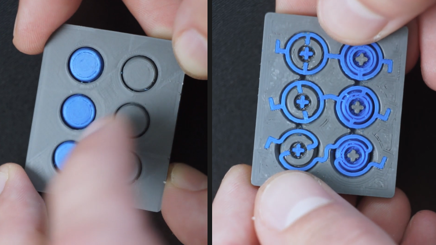
These nifty buttons come from [Marc Schömann], and they are intended to cover just about any kind of tact switches. The buttons, their cover, and the compliant bits that act as a spring can be 3D p…
proud siren
Ohhh, I see what you mean. Thank you, that makes sense
vast flume
As some of you may remember/know, for the past year or so (through multiple big design changes) I've been working on creating an altimeter for skydiving. Started off as an esp12f powered board that just had some lights and sensors to now being powered by an stm32, having lights sensors and a display. I made a mistake on the latest iteration and used 8 bit parallel without knowing how terrible of an idea that was. There were also some issues I made with the power circuit for the display, as the datasheet was terrible. So pretty much, my question is, what display/driver would you guys recommend for me to use? I don't need a fast refresh rate at all, 1hz would be fine. The display I currently have is an ftsn lcd but I also started looking into epd's.
dry pelican
Ssd1306 OLED displays are versatile and low power. They're also cheap
supple pollen
I'm thinking eInk or maybe one of those Sharp memory displays might make sense. Or possibly one of the Ynvisible ones if they're available with the capabilities you want
dry pelican
Also some sort or SPI LCD from <online retailer> would work
dry pelican
supple pollen
It sounds like you'd want a gated sample-and-hold sort of circuit in the PLL tra...
That's exactly what I was going for with the bilateral switch that connects the low pass filter and the phase comparator output. I think that I'll just use the interrupter output that switches the coil off to also switch the bilateral switch because the VCO frequency will lock immediately instead of locking after a capacitor discharges beyond a certain threshold (which could cause the frequency to drift out of resonance).
 hearty ocean
Hi all, I'm working on a project that needs a PN2222A transistor to activate an LED on GPIO (using circuit below), however these KSP2222A transistors (advertised as PN2222: https://www.adafruit.com/product/756) aren't working the same as my PN2222A -- the LED is about half as bright when triggered. Is there a major difference between these two transistors that I'm missing?
Edit: Looking at the datasheets, the only major difference seems to be collector current (1A for PN2222A vs 600 mA for KSP2222A). Would lowering the 330 Ohm resistor solve this?
 distant raven
hearty ocean
Hi all, I'm working on a project that needs a PN2222A transistor to activate an ...
distant raven
hearty ocean
Hi all, I'm working on a project that needs a PN2222A transistor to activate an ...
Make your 10k like a 5k
You likely need more current to saturate the base.
supple pollen
Note there are some variants (like P2N2222A) with different pinouts, and transistors will have less gain hooked up the other way around.
dry pelican
Maybe also decrease the 330 ohm resistor since NPNs have a voltage drop of about 0.6v across the collector and emitter
But madbodger is probably right with the flipped pinout
woven bluff
supple pollen
Basically it adjusts the pulse width/duty cycle. <https://www.analog.com/media/...
It did not say what FB does when not pulled to ground

I don't know how error amp would behave when one input is floating
looks like current amp does not directly control the driver
so, when FB is not needed, Vc should be tied to something static so current should get exclusive control?
not sure what to do with the third error amp that compare VIN and primary side ringing
woven bluff
$200 went to OSH Park, this really is an expensive hobby...🙃
cloud cliff
I have a moped with a dynamo that supplies "6v" AC to the lights, that i want to install 12v led lights on. I initially thought i could just get away with a full wave rectifier and a large filtering capacitor, but that now seems quite... expensive
I measured the real voltage at the lights, and it came out as 4-50V rms depending on the engine rpm. If i understand correctly that means that with the slight losses of the full wave rectifier i'll get nearly 70V dc at the output at full rpm. I also calculated that with at idle the power coming from the dynamo with the rectifier will be ~50hz, so with the 4v(ish) 1A im drawing, i'd need a ~30000uF 100V cap, and that's expen$ive (3*50€) (and also still a full volt of ripple)
Also the voltage regulator that i planed on using only goes up to 50V
is there any more reasoanable option for converting ~50-130hz 4-70V choppy DC (from the (large, 50A 1000V) full wave rectifier) to a smooth 12v DC (drawing 6W, though i would also like to add some supercaps so the lights will glow after i turn the moped off, so i might momenteraly draw ~20w)
cloud cliff
If i could somehow make the input always be at ~25V AC i could just us a ~4000uF 50/63/100v cap and be done with it
spice turtle
cloud cliff
I have a moped with a dynamo that supplies "6v" AC to the lights, that i want to...
that seems to be quite a variance. 4VAC? You wont need that large of a cap actually. I think I had heard that a good rough estimate is 10,000uF per Amp. You can get away with a lot less. You also dont need one single cap, you can get away with multiple ones in parallel.
You could use a pre-regulator to drop it down even more, just a simple zener diode with a transistor for power before your main regulator.
Zener,Diode,voltage,transistor,current,circuit,power,supply
supple pollen
Maybe a simple circuit to clamp the voltage to 50V maximum or disconnect the input when the voltage rises too high. However, if you're considering a bridge rectifier and capacitor "expensive", then stuff like preregulators and clamping circuits may be prohibitive
spice turtle
🤔 you know, they could technically use a 12VAC transformer too! Might be bulky but they can get them on ebay or digikey
vast flume
I am trying to read from a bmp581 over i2c with an stm32, however when I read from the fifo buffer the read data remains in the buffer, even though new data is appended. Once the buffer fills up new data stops coming in. Also, the registers for reading the current temperature & pressure data values are not getting new readings either. Has anyone else experienced this? I can't for the life of me figure out what I'm doing wrong
unreal flax
vast flume
I am trying to read from a bmp581 over i2c with an stm32, however when I read fr...
How are you determining that the data remains in the FIFO? Do you get the exact same bytes on subsequent reads? Is there any chance that the second read is actually failing and you're just looking at the same buffer in memory again?
vast flume
unreal flax
How are you determining that the data remains in the FIFO? Do you get the exact ...
I'm using the debugger to inspect the local memory on the stm32 after reading from the sensor. I'm getting the same bytes on subsequent reads, with new dataframes appended after until the fifo buffer is full (at 15 dataframes which lines up with the datasheet)
What do you mean by your last point though? That could possibly be the issue honestly
Also another thing that has been strange is I seem to end up also reading the register that stores the count of stored dataframes in the fifo if I try to read 24 bytes (4 dataframes?) at once. Very confusing since the register for the fifo count is well before the fifo data buffer. I was thinking maybe I was having an int overflow somewhere but I think I've been able to rule that out
unreal flax
Hmmm, well if you're seeing new data showing up, that indicates something is happening. How are you choosing how many bytes to read each time?
vast flume
I configured the fifo to store temperature & pressure which would be 6 bytes according to the ds

So I'm just reading it like this:
uint8_t temp_arr[6];
BMP_Reg_Read(BMP_FIFO_DATA, 6, temp_arr);
void BMP_Reg_Read(uint16_t reg_addr, uint16_t reg_size, uint8_t* data_output)
{
    HAL_I2C_Mem_Read(bmpConfig.i2c_config, (uint16_t)(bmpConfig.address<<1), reg_addr, reg_size, data_output, reg_size, 100);
}
Something is a little weird in the Read() call. The two reg_size parameters have different uses. The first should be the size of the the address, I think, which would be 1 byte.
unreal flax
Yeah, if there's more than 256, you could see a 16-bit address sometimes. I can't think of an example off the top of my head, though.
vast flume
Ah interesting, didn't know that
Trying now with it set to 1
omg
I can't believe that was it 😭

24deg c 😎
Thank you so much!
unreal flax
Great! So what was probably happening is that it was sending a bunch of 0x00's after the address, so you were really reading registers starting at 0 instead of the FIFO, I'd guess.
vast flume
Yeah that makes total sense now. Was wrapping all the way around such that it somehow was 24 bytes before the fifo count register lol
Crazy coincidence
unreal flax
Yep, that matches. It's address 0x17, so it would be the 24th byte read if it started from 0x00.
cloud cliff
spice turtle
that seems to be quite a variance. 4VAC? You wont need that large of a cap actua...
10000uF is a good estimate if i'm getting 4V 60hz (120 trough the rectifier) electricity, but i'm getting 25hz(×2=50hz) at the input, so even a perfect world the 10000uF cap will give me 3V ripple (that's probably fine for the lamps, but idk if the voltage booster/regulator i'm using will handle that)
@supple pollen
With all the supercaps and voltage regulators/current limiters the price would be creeping north of 200€ on a moped that cosy me 500€ lol. A simple voltage clamp would probably be fine atleast price wise (i can't disconnect the input because then i wont have lights while going 40kph down some dark backroad at 1am), but i'll still have the problem of the voltage being too low at idle. Is there a sinple circuit that progressivly changes the current going to one component smoothly to another when the voltage rises (and disconnect the 1st component when the voltage gets wayy high). I could then use some cheap 30000uF 35V cap(s), and a smaller higher voltage cap when the engine rpm and voltage rise (5000uF 100V)
woven bluff
is Q Package 5-Lead Plastic DD Pak the same as to-263?
spice turtle
cloud cliff
10000uF is a good estimate if i'm getting 4V 60hz (120 trough the rectifier) ele...
Where are you getting 3V ripple from? I can tell you it will be no where close to that. Maybe 30mV, but not 3V. Usually voltage regulators can handle ripple, maybe not 3V but they can probably handle 100mV or so
supple pollen
cloud cliff
10000uF is a good estimate if i'm getting 4V 60hz (120 trough the rectifier) ele...
What current draw are you using to get these figures?
cloud cliff
spice turtle
Where are you getting 3V ripple from? I can tell you it will be no where close t...
I/(2•ACfrequency•V)
So 1.5A/(2•25hz•1V)=0.03F=30000uF
cloud cliff
supple pollen
What current draw are you using to get these figures?
4V at idle, so 1,5A (6w)
supple pollen
Let's back up a step. Where are you getting 6W?
cloud cliff
Basically from nothing, the leds that are available for the ba15s bulb socket are pretty inefficient, and fairly bright. The tail light doesen't draw that much, maeby a watt. I know how 4w of led light looks like, and those bulbs i have in my home are for sure more efficient and less bright than the ones i have fitted on my moped.
spice turtle
I really think you'll be OK with such a small load. LEDs can handle ripple, in fact some converters basically forgo a rectifying diode all together and just feed them pulses.
cloud cliff
Oh yeah they'll be fine. I just don't want them to flicker. Leds are technically illegal to fit on a moped that isn't aproved for them (though nobody really cares), so i'd like them to look like incandescents as much as possible
I could just string a series of batteries together and measure the power consumption though
supple pollen
I think your ampere calculation is off, and you can get by with much less capacitance
cloud cliff
cloud cliff
I/(2•ACfrequency•V)
So 1.5A/(2•25hz•1V)=0.03F=30000uF
This is off or you think they don't draw 6w?
supple pollen
I think they only draw 6W at full voltage and less at lower voltages.
Additionally, where are you getting 60Hz?
cloud cliff
supple pollen
Additionally, where are you getting 60Hz?
more like 50, the moped idles at ~1500rpm (rotations per minute), and 1500/60sec is 25. So the engine rotates 25 times per second, and with each rotation of the engine the ac cycle goes down and up one time. So trough the full bridge rectifier that's 50 peaks a second (yeah not technically ac 50hz, but 50 peaks a second)
cloud cliff
supple pollen
I think they only draw 6W at full voltage and less at lower voltages.
i'd like to get the full power from the leds, so it would be ideal if i could use them at full voltage, so i can like, see infront of me more than three meters
supple pollen
So you want full power at low voltage? The easiest way forward is probably a small battery.
The 12V 7Ah batteries used for emergency lights are inexpensive and common
You could probably also use lithium technology, but for such exposed to outdoor condition use, I tend to stick with old fashioned reliable SLA.
cloud cliff
no i want full power at full voltage on the leds, when the moped idles. One solution that i have already come up with is to use bigger lower voltage caps when the moped idles and somehow to switch to smaller higher voltage ones when the voltage increases. I just don't know how to do that.
cloud cliff
supple pollen
The 12V 7Ah batteries used for emergency lights are inexpensive and common
yes, but the i'd have to remember to keep it charged. It's also heavy and i don't really have any space to fit it on the moped
supple pollen
You wouldn't just charge it from the existing alternator? Basically, it would get topped off when you're running above idle, and drawn from when you're at idle.
cloud cliff
with ac?
the moped doesen't have a battery, i'd ofcourse be taking the power from that if there was one
supple pollen
No, you'd still rectify it
Yes, I'm suggesting adding a small battery to the moped.
cloud cliff
and i'd still need to regulate it, lead acid batterys don't probably really want to charge at 40v
supple pollen
Yes, battery charge regulators are common parts for bikes, mopeds, tractors, and the like. It wouldn't really charge at 40V anyway, the battery would drag down the voltage as it absorbed charge. How it would balance would depend on what type alternator you have.
cloud cliff
the alternator coil that goes to the lights goes ONLY to the lights and nowhere else
supple pollen
I assumed you were going to reroute it through a rectifier anyway?
supple pollen
You'd have to do that for the capacitor anyway...
cloud cliff
yes, i have small creavices where i can 3d print multiple boxes and put diffrent parts of the rectifier/regulator there
A battery is just a big hunk, i have nowhere to fit it
maeby on the rear luggage carrier with cargo straps or something, but i suspect the police won't really like that
supple pollen
An NP-7 is about the same size as a big capacitor, and there are plenty of smaller ones available

One of those, and a regulator like https://mechanicsurplus.com/products/3597489125 and you have a nice DC supply of 12-14.4V for €30 or so.
cloud cliff
supple pollen
One of those, and a regulator like <https://mechanicsurplus.com/products/3597489...
and is thet regulator happy with the 50V the dynamo will push when not being drawn power from?
supple pollen
Yes, it's designed for exactly that sort of use. It also includes the rectifier, so it's a one-part solution.
cloud cliff
well i'll have to vandalise the cables a bit to make the work but otherwise it's fine.
So if the lamps draw power to the lamps even when it's being charged trough that battery, they'll still get a flat voltage?
supple pollen
You'd have to do that anyway, I'm guessing. The battery acts like an enormous capacitor, but with less voltage variation. So when you're revving the engine, you'll get 14V or so out of the battery. At idle, or with the engine off, you'll get 12V or so.
cloud cliff
Ok, so then i'll just buy one of those. Just have to remember to net leave the lights on because the battery will go flat in less than 3h.
supple pollen
Exactly.
There are ways to automate that if desired (basically when the engine kill switch is actuated, it shuts off the lights)
cloud cliff
the moped doesen't have an engine kill switch
supple pollen
How do you shut off the engine? Just turn off the fuel supply?
I found this handy wiring diagram at Revival Cycles
 cloud cliff
no, it's got a decompression valve
supple pollen
Ah, that's interesting. You could probably add a switch to that if you wanted, or just remember to turn the lights off.
cloud cliff
supple pollen
I found this handy wiring diagram at Revival Cycles
"OEM fuse", lol, no fuses
supple pollen
It's not like in a car, where you can't start the engine if the battery is dead anyway.
I like to have fuses to protect my wiring (the battery can push a lot more current than the alternator if there's a short circuit). But that's a personal choice.
cloud cliff
Well yea i'll probably add one
i don't mean that someone took it out, it didn't come with one from the factory
supple pollen
Yeah, some of these things are pretty bare-bones.
cloud cliff
oh this is way tighter than i remember it being, i'm gonna need a smaller battery (toothbrush for scale)

like a 3x4x15cm would baeby go in there
oh not even that, more like 3x2x15cm battery
and that's pushed right up to the engine
i would go lithium, but if my mounting is bad and it falls ontop of the engine i'm gonna have a bad time
supple pollen
Yeah, you were never going to fit a 35000µF capacitor in there.
cloud cliff
yeah but wait what am i doing
i have a device that turns whatever volts ac into solid dc (battery charger)
i can just use supercaps
(and an extra charge/voltage regulator)
also 3•10000uF, and that defineatly does fit
oh yeah no supercaps are really expensive
vast flume
Well if anyone wants a library for using the BMP581 with an stm32, I made one which can be found here: https://github.com/kkingsbe/STM-32-Libraries/tree/main/BMP581

GitHub
Contribute to kkingsbe/STM-32-Libraries development by creating an account on GitHub.
 rapid garden
is it just me, or does this filter seem to be more resonant at negative voltage than positive (bottom graph)? why would that be?

for context it's a switched cap vcf using noise + comparator instead of pwm. resonance path has diode clipping to prevent self-oscillation
supple pollen
It may just be hitting the rail
rapid garden
i found the cause, turns out even though JFETs are "symmetrical" they ever so slightly bias
fixed it by putting n-channel on the first stage and p-channel on the second so their biases cancel out
glass wolf
Hello everyone, i am trying to learn pcb design by myself and using easyeda for design.
Any idea why this cap and also other caps which is connected to VDD their footprints both on GND
Any suggestions?
Thanks!!

 spice turtle
that seems like an error 🤔 check the signal name for that cap on both ends
hushed smelt
@glass wolf Where did you get the capacitor footprint from? Are you using one drag and dropped from the Commonly Library or is it perhaps a custom user footprint?
hushed smelt
Is it giving you any net flag errors in schematic view when attempting to "update PCB"?
something like this?

If you don't have a pin header or other kind of pin attached to the 3V3 net it will throw an error about incomplete net. You can get around that by giving it a pin header like this.

no errors

Check your net label for the individual GND pad that is on the incorrect net.

Relabel the Net with the correct net you want. In this case 3V3 and it should automatically connect back to 3V3 net.

If it changes back to GND after a schematic update then the problem is in your schematic not PCB view.
In which case you need to figure out why 3V3 net is changing to GND net. I did try it myself and found some odd behavior. Possible bug.
Do not ignore netflag errors. They're as important as DRC errors but for schematic view.
The problem, I think, GND is a valid net and so is 3V3 so if it's switching to a different valid net that's a sneaky kind of bug and might be something to report to EasyEDA in their forum.

 dry pelican
Looks good. It could be compacted more though
Maybe put the ICM20948 under the feather and mount it on the other side
Make sure to make the pinout work if you're doing reverse mount of course
 narrow jetty
dry pelican
Looks good. It could be compacted more though
narrow jetty
dry pelican
Looks good. It could be compacted more though
thank you i will work on making it smaller in mk2/3 i will try about putting the icm under it
proud siren
I have a series of naive question as I have no industry experience in this area. I have a working prototype of a product using the Huzzah esp32 board from adafruit.
- If I wanted to hypothetically mass produce the prototype I made (ie, 100 units), would it be cheaper to design a custom PCB that only has the components I need (microcontroller, some input pins, BLE chip)? Or is it roughly the same cost as just buying a bunch of these feather devices?
- The places that make your custom PCBs -- will they also write my firmware to each device or is that on me?
- In general, when someone is making a new electronics device for the purposes of selling many units of it, I imagine they don't buy a bunch of boards and then solder on the buttons manually, screwing each board into a case, etc. Who provides the surface of assembling an electronics device once you have a designed PCB and firmware?
Apologies if these are obnoxious, I wasn't sure how to google this.
 fervent lance
proud siren
I have a series of naive question as I have no industry experience in this area....
fervent lance
proud siren
I have a series of naive question as I have no industry experience in this area....
- it depends, sometimes you can get cheaper designs, sometimes you don't, considering only hw cost and not devolopment
- you should ask them but most do
- manufacturers such as jlc do often provide assembly and other services (just dm them if something is not included, they might accept your porpose), some other people although prefer manually soldering their stuff due to cost, or not dealing with knock offs or whatever
proud siren
Wonderful, thanks so much for these answers!
 bright cape
friends... I'm beating my head against a stick on this one....
reed switch is used to swithc the system on, then the PA6 of the MCU should pull the gate of the PMOS low and keep the VBAT flowing to VDD until the MCU goes to sleep and put PA6 HIZ Z (thus, cutting power to the entire MCU). Theory is good, I think.
but the MCU comes on regardless. I thought maybe it was current going through R1 INTO PAD6, and through ESD cell or something?
I increased R1 to 100K, no change.
I even removed R1. no change
 supple pollen
bright cape
friends... I'm beating my head against a stick on this one....
reed switch is u...
supple pollen
bright cape
friends... I'm beating my head against a stick on this one....
reed switch is u...
I'm guessing the protection diode on PA6 is conducting, because when Vdd starts to drop, PA6 becomes higher than Vdd.
bright cape
i figured it was something horrible like that. I might either switch out Q1 for a proper load switch, or add an NMOS between PA6 and the gate of Q1 to pull it down properly. that'd likely isolate VBAT from PA6.
i'll have to invert the output of PA6... no biggie
thank you @supple pollen - you gave me some good stuff to think about
ok - i cut the trace between PA6 and the gate -- and the board doesn't come on!
(tha'ts a good thing)
and, by grounding the gate, it switches on beautfully.
 rigid fiber
EasyEDA PCB is putting a nunch of through holes underneath my ESp32-S3 chip, in the 3x3 grid of ground contacts for the chip. But this means that the centre contact can't be routed to anything because the usual 0.254mm trace conflicts with the design rules by getting too close to the through holes. Do those through holes really need to be be there underneat the esp32-s3, or can i remove them?
rigid fiber
Hmmm... ot looks like they were put there by the footprint of the part. Can't remove them.
dry pelican
You can edit the footprint and move or remove the vias if you want to
But usually you want those vias for a solid connection to ground and heatsinking iirc
supple pollen
Yeah, they don't have to be connected, but normally they're connected together anyway.
 lone basalt
I'm trying to wire up a RPI 2040 in easy eda, I'm having issues with track width on the pads, if I make DRC happy I can't connect every pad, but if I shrink the track so that I can, DRC gets mad, what should I do? I've found where to edit the design rules, and what JLCPCB's minimum is
 ocean coyote
has anyone messed with pio usb? on the pico
im looking to connect a st7735 lcd with sd card slot, and 5 buttons alongside a female usb a port setup as a host to relay packets through
i need the micro usb set up as a usb device setup to appear the same as the device im plugging in
the issue im having is im currently using the pins I believe are associated with pio usb

also being a pico w, I think that the wireless chip uses spi on pins 23 24 25 29
does that interfere with the spi busses ive chosen for the lcd or sd card?
latent jungle
The native USB signals are not broken out to the edge pins.
And yes, one of the SPI ports (SPI1) is dedicated to the WiFi module. (You can use the SPI port if you are not using the WiFi module.)
There are two available on the RP2040 / Pico
Page 13 of the RP2040 datasheet has a table that shows the muxing of the pins and various functions: https://datasheets.raspberrypi.com/rp2040/rp2040-datasheet.pdf. (Or the pinout diagram https://www.raspberrypi.com/documentation/microcontrollers/raspberry-pi-pico.html.) Use that to determine which pins you should use to access SPI0.
ocean coyote
latent jungle
The native USB signals are not broken out to the edge pins.
sorry I should have linked this https://github.com/sekigon-gonnoc/Pico-PIO-USB
I believe its also integrated into tinyusb now, so the plan is to use tinyusb and this pio usb to have a pass through as such
latent jungle
ocean coyote
sorry I should have linked this https://github.com/sekigon-gonnoc/Pico-PIO-USB
...
where on your diagram is that indicated?
dry pelican
Does Adafruit have the schematics for those pico-based brains boards that are used for testing newly manufactured boards?
Those use the pico as both USB host and device
ocean coyote
latent jungle
where on your diagram is that indicated?
its not yet, but its going to use gpio 0 and 1
ocean coyote
dry pelican
Does Adafruit have the schematics for those pico-based brains boards that are us...
good point
ocean coyote
do you remember what there called?
dry pelican
But it is understandable if they don’t want to open source their internal testing things
They’re just called brains boards iirc
Maybe someone in this server who works at Adafruit has info
latent jungle
ocean coyote
its not yet, but its going to use gpio 0 and 1
No worries. My bad for wasting my time on a question not actually documented.
ocean coyote
dry pelican
They’re just called brains boards iirc

You're probably really used to microcontroller boards with USB, but what about a dev board with two? Two is more than one, so that makes it twice as good! And the Adafruit Feather ...
dry pelican
I forgot that that one just released lol
ocean coyote
was there another?
ocean coyote
do you think id encounter issues with current without a battery attached?
the usb devices i will be plugging in draw around 300ma maybe more
dry pelican
No. Shouldn’t be an issue if trace thickness is at least 0.5mm
And usb is spec’d for at least an amp iirc
rigid fiber
This spec sheet from JLCPCB is all in Chinese. Is that a 5 pin relay just with doubled pins to control multiple items?

Oh fudge, I just realised that I was concentrating so hard on getting to the PCB stage that I forgot relays in my fan project. As it stands now there no way to turn them off, only slow them down. D-:
hushed smelt
How to control 12V RGB LED's for a shop lamp from a 3.3V feather.? I'd prefer to control the RGB's from a feather even though they'll be 12V RGB's

The lamp is currently 2 rows of 5V white & yellow LED's powered via 5V USB. About 60 white & 60 yellow tiny LED's.
I'd like to make a 12V custom ring PCB with 12V RGB's for a much brighter shop lamp.
How to control the dimming, on/off, using a 3.3V feather as the controller? Is that possible?
unreal flax
Are you planning to use 12V smart LEDs, or regular LEDs that you are controlling via PWM?
supple pollen
rigid fiber
This spec sheet from JLCPCB is all in Chinese. Is that a 5 pin relay just with d...
No, it's an 8 pin relay. 2 pins for the coil, and 3 pins apiece for two sets of form C contacts.
hushed smelt
probably a matrix of 12V RGBW's with built-in driver chips in each LED. I don't like dealing with external driver chips.
Will try to use much bigger LED's maybe the 4mm variety or whatever the big ones are.
unreal flax
You might need a level-shifter to go from 3.3V to 5V for the data line, then, since I think the 12V varieties tends to have higher logic levels, but that's worth checking in the datasheet of the LED you pick.
hushed smelt
good point I haven't even started looking at data sheets. if i could control 12V LED's with 5V that would work out so much easier.
unreal flax
You should be able to. It'd be rare for them to need 12V logic.
hushed smelt
Can't find any 12V RGBW 5050's with built-in I2C 😦 Seems like they all require separate driver chips.
supple pollen
Most of the drivers I've seen either use a timing based one-wire protocol, or a synchronous bipolar protocol (like SPI, but unidirectional). I haven't seen a synchronous unipolar one like I2C used.
Individually addressable 12V LEDs would be very inefficient anyway. Most of the 12V addressable strips use separate LEDs in groups of 3.
If you were going to run R, G, and B LEDs at the rated 20mA from a 12V source, you'd be dropping 9V apiece for the blue and green ones, and 10V for the red one: over half a watt of wasted power to dissipate! A 5050 package wouldn't last long under those conditions.
dry pelican
Yeah. Might be better to put in a buck converter to 5v so that neopixels can be used
 wild glade
Does this look compliant?


Should I keep the P1x.x in the name? I've added those as a alternate pin names
Same for ALE/PROG, PROG is added as alternate definition with input set as type
hushed smelt
supple pollen
Individually addressable 12V LEDs would be very inefficient anyway. Most of the...
After looking at 12v strip designs i realized its all just 3v or 5v led’s run in series. I had no idea it worked that way. Why would anyone do that instead of running them at 5v? Save money on resistors? Makes no sense when i2c leds are so much easier to deal with.
wild glade
(It's KiCad, by the way)
hushed smelt
Like, it doesn’t make them any brighter in series at 12v. I don’t get it. Maybe at one time the price difference made it a more cost effective way to do it?
Think ill just go the neopixel route and make everything easier. Thank you for the advice. 🤗
wild glade
Also, how would I deal with the alternate pin numbers of different footprints?
supple pollen
I normally put the signal name on the symbol and only tie it to a specific pin when combining a symbol and footprint into a device.
wild glade
Fair, designing it for DIP so I'll just keep it as is
unique patio
hushed smelt
After looking at 12v strip designs i realized its all just 3v or 5v led’s run in...
I think 12V is a semi-standard voltage for low-voltage applications: lots of power supplies available, etc. Also you can use thinner wires because the current is lower
incandescent 12v bulbs were very common, so maybe originally these were drop-in replacements.
hushed smelt
unique patio
I think 12V is a semi-standard voltage for low-voltage applications: lots of pow...
That makes sense. Can get away with longer & thinner wires with lower current. Thank you.
supple pollen
However, you can only get the lower current if you run multiple LEDs in series, which means they aren't individually addressable, but addressable in groups.
wild glade
What does C A and B mean here?
 unreal flax
Those are "GD&T" symbols, giving some subtle mechanical-engineering information about what the measurements are in reference to.
wild glade
Ahh, now to figure out what datum means in this context, fun not having english as my main language, but, TIL 🙂
Manually naming 486 pins is fun tho 
Why can't I just say "this is 0,0, the rows are this, the columns are that"
Oh well, guess it's occupational therapy
supple pollen
I think "Datum" in this context means "the point from which everything else is measured"
wild glade
wild glade
Why can't I just say "this is 0,0, the rows are this, the columns are that"
Turns out you can

I hope I did it right
Not worried about missing or misplaced pins though

Just that index mark
hushed smelt
supple pollen
However, you can only get the lower current if you run multiple LEDs in series, ...
That makes sense too since the current lamp has only yellow or white LED's and not individually addressable.
wild glade
So many pins 
I'm sharing the files when I'm done, nobody should have to do this much work lmao
 formal scroll
Can someone here recommend me a tutorial for using an arduino to make a PWM controller for a 12v motor that needs to run for a set time, be reversed in direction, then stop? I am building an automatic litter box using a 12V DC motor with gear reduction. I have been looking on amazon for a good controller but I don't know which one is reliable and the one I saw with a timer doesn't sound like it will reverse motor spin, and I was hoping someone had experience with this so I can build this cheaper than the exorbitant cost of the automatic litter boxes available. Thank you for any information you can provide me!
rigid fiber
OK, I think this is the final version to be sent to JLCPCB when the outsources parts arrive. https://oshwlab.com/coryca/esp32-s3-pwm-fans Hopefully in 2 weeks I will have the PCBs.
In EasyEDA open source hardware lab, open source square pools all kinds of electrical design engineerings together to realize resource sharing easily.
supple pollen
formal scroll
Can someone here recommend me a tutorial for using an arduino to make a PWM cont...
An easy motor controller is the AdaFruit Motor Shield, which supports variable speed and reversing, and is reliable. Another possible choice is the Crickit. Normally to run something for a specified time, you'd get a timestamp, add the desired period to it, then start the action, and loop until the current timestamp is greater than or equal to the computed timestamp.
formal scroll
I figured it out , thank you though. I am using a 12V 150W DC mnotor with a 43amp driver module I found on amazon. I have to make sure its more than powerful enough to roll a barrel with possibly 50lbs of cat p 00 and sand. LMAO not allowed to type a relatively benign word
dry pelican
For 43A, it's probably best to use a relay instead of something solid state. Because any mosfet or igbt powering an inductive load will have to be huge and there will have to be a huge flyback diode. A relay is a much simpler device (if you don't need speed control) and it is much more robust. You do still have to take into account the inductive spiking since arcing can damage a relay, and n inductor with 43A going through it is going to want to keep 43A going through it (motors are not purely inductive, but it gives a good maximum to design for).

 distant raven
hushed smelt
19" Workshop Lamp PCB
distant raven
hushed smelt
19" Workshop Lamp PCB
Who are you trying to fab through?
hushed smelt
Probably have them assembled by JLCPCB, uses LCSC parts that it says are in stock.
They assembled the Bleeding Rainbow strip and I'm pretty happy with those results.
hushed smelt
One of the nice things about using EasyEDA is the direct integration with JLCPCB & LCSC. I know it geared to drive sales to them and I'm fine with that. The EDA works well, easy to use, and it works for me.
supple pollen
I'd be tempted to make a bunch of concentric rings if the cost were about the same
hushed smelt
Oh, yeah umm I haven't checked yet. 😅
I thought about that but I really don't have the use for them and having a bunch of rings would be very expensive. Pretty sure I'll only get charged for the 1 ring and not the center volume.
since minimum order is 5 it's going to be expensive enough as it is.
i'll have 4 left over hopefully for some other projects. maybe a drone with ufo lights? who knows.
supple pollen
I'm used to being charged for the smallest rectangle that can enclose my board, but it's possible they do clever-enough panelization to put something else in the open area inside the ring, or they compute prices using a different metric. I did a run of boards that cost me $75 for the boards alone a while back.
hushed smelt
$514 👀
$200 additional charge for the extra large size. $100 engineering fee. oof.
Think I'll just zip tie a flashlight to my lamp now. 😦
supple pollen
You might consider making it in 90° arcs like the larger AdaFruit LED ring, it might be a lot more cost effective.
hushed smelt
aha and minimum order is 5, genius
supple pollen
Good point! I did take advantage of that sort of scaling in a few builds. Like my 24-channel light dimmer, I just had a trio of 8-channel boards made at OSHPark.
 dry pelican
72 degree angle PCBs. Now you can use all 5 for a complete circle 😛
Another option might be getting a premade neopixel strip an using some sort of partial conical reflector. But partial conical reflector will be hard to find unless you have necessary metalworking equipment.
hexed mural
hushed smelt
$514 👀
WOW
hushed smelt
dry pelican
72 degree angle PCBs. Now you can use all 5 for a complete circle 😛
Even better, that cuts it down to 20 LED's per section.
hushed smelt
@dry pelican 72 degrees 👍
 dry pelican
Nice. How will you connect the boards?
Also, I just suggested the 72 degree boards as a joke, but I guess it also makes practical sense
Are you getting them assembled by JLC?
dry pelican
hushed smelt
5V 6A full power. 😬
That will be extremely bright tho, and because the eyes work logarithmically, it isn't that much brighter than a lower control level to the neopixels
but 30W is actually pretty reasonable for LEDs
with power losses might be like 25W
hushed smelt
Brighter the better, I can control the brightness with circuit python 😉
I just hope they'll be bright enough.
wild glade
hushed smelt
19" Workshop Lamp PCB
modularize every individual LED or small groups, and 3D print a ring instead, that allows you to keep PCBs square and/or panelized boards
dry pelican
At full brightness, that thing might be able to light up a whole room depending on efficiency
wild glade
should be cheaper
hushed smelt
wild glade
modularize every individual LED or small groups, and 3D print a ring instead, th...
dry pelican
also, the white tends to have a very bad color (it's more blue and it makes the colors of certain things look wrong). Maybe gamma correction or something would help
but the best option is to use RGBW
wild glade
hushed smelt
https://www.printables.com/model/452082-solder-webcam-lamp
Interesting, then deffo make little square boards and hide them behind a diffuser
wild glade
dry pelican
also, the white tends to have a very bad color (it's more blue and it makes the ...
Sticking to white Cree LEDs won't give you the good warm white? 😛
hushed smelt
I can gamma correct np
dry pelican
but the separate rgb channels still make a lumpy spectrum. Still better than most lighting strips
hushed smelt
yeah, we'll see how it goes
i really don't want to redesign it for a 3rd time using RGBW instead with a different footprint. spent all day on this one.
Looks like it'll be about $100 total
If it works as a bright lamp it'll be worth it. My current one is on the fritz and dying.
gah plus shipping is $133, well at least it's not $500.
this is going to be the most expensive lamp i've ever owned
hexed mural
Doesn’t Dyson make a crazy expensive lamp? Time to order the full ring in one piece and take the crown!
hushed smelt
lol no thank you. they can keep that crown.
if it works the best part is i'll be able to tell people my lamp sucks
hexed mural
But what if you make it so you can remove the ring and also wear it as a crown
hexed mural
https://www.dyson.com/lighting/desk-lamps/lightcycle-cd04/black-black you’re close! It’s $600
hushed smelt
there's no way that's for real. it's a tiny bulb in a stick
and it doesn't even suck
hexed mural
Oh it’s real. The floor lamp version is like $850
hushed smelt
now i'm gonna have to 3D print that as a parody and power it with circuit python
and i'll market it as "designed to reduce wallet strain"
hexed mural
There’s some patent around the sliding mechanism, which is actually pretty cool. Not $500 cool but still. There was a hackaday article about someone trying to reverse engineer it
hushed smelt
it's two sticks... lash them together with twine and call it Casablanca Shiek style.
pic from far away almost makes it look like 3D printer v-rollers which would actually make a pretty cool automated lamp
a single stepper motor in a base with a long lead screw, height adjustable lamp...
hexed mural
You mean like this https://hackaday.com/2023/01/02/diyson-lamp-hides-cables-between-the-seams/

[Steven Bennett] is so fond of Dyson’s new Lightcycle lamp that he’s decided to clone his own version in the spirit of the original. Dyson, however, knows what makes their lamp so speci…
hushed smelt
You can hide cables with roller bearing channels that transfer power. Cars use them for dimmer switches and they only cost like $15.
dry pelican
hushed smelt
gah plus shipping is $133, well at least it's not $500.
Shouldn't be that expensive. Usually shipping goes up like that if the package gets really big. But a lamp is not $133 big
hushed smelt
Already added everyone who helped into next weeks circuit python meeting hug report. Thank you all for the advice, that was a great discussion.
hushed smelt
dry pelican
Also, I just suggested the 72 degree boards as a joke, but I guess it also makes...
Oh sorry missed your questions up there. No, your advice was spot on. I'll daisy chain them with some hookup wire. Each panel has 3 mounting holes. I can heat set insert screws into the 3D printed light housing where ever I need. Even though it might have been an off the cuff joke from your perspective it was absolutely the right answer.
turn their 5 PCB minimum against them. 😛

 supple pollen
Because it's pretty narrow and only anchored at one end?
formal scroll
@dry pelican thank you for the additional information! I plan on running the motor at half power and that means the driver will be running at almost 1/8th load, is this design still cause for a rethinking of the parts I will be using? I have way more skill in programming than I do in hardware/electronics so I can't really answer these questions for myself. I bought two of these items for controlling the motor.
https://www.amazon.com/BTS7960-Driver-Module-Arduino-Current/dp/B07TFB22H5/ref=sr_1_8?crid=ZHGZ27SO7XM4&keywords=h+bridge+motor+driver&qid=1682422373&sprefix=h+bridge+motor+driver%2Caps%2C86&sr=8-8
And I am using this motor
https://www.amazon.com/gp/product/B07K9KPDNV/ref=sw_img_1?smid=A18IHNL4DD28Y&th=1
I don't see a relay on them.
I almost forgot to mention, I will be buying a more expensive, name brand, quality powersupply. This will be going upstairs in my home out of sight for essentially the entire day so I wanted the assurance that comes with "you get what you pay for" so far as firesafety goes. Would anyone have a recommendation for a 12v power supply that fits that perspective?
supple pollen
Mean Well makes some solid supplies at a reasonable price point. I don't really recommend buying stuff from amazon if you're interested in safety (or at all, really).
dry pelican
That motor does not look powerful enough. It says 3.97kg*cm for rated torque, and you can calculate the maximum load. Using pwm to control speed also limits power. A better option would be to use a belt or something for mechanical advantage.
formal scroll
I am printing a gear reduction for it so it has more torque
woven bluff
supple pollen
Mean Well makes some solid supplies at a reasonable price point. I don't really...
I had a failed meanwell boost, then I switched to XP powers and Recom
amazon and ebay SMPS are definitely Chinese junk made with cheapest parts possible
I had one coupled SEPIC module that arcs inside the core
dry pelican
formal scroll
I am printing a gear reduction for it so it has more torque
Do you know how much power you need?
Maybe you don't need the whole 516W of motor power
And that motor cannot supply that amount of power
516W is almost 1 horsepower
formal scroll
there are like 20 motors listed on that page, I got the 150
or wait hold on
yeah I got the 150rpm at 150 watts
I am using a driver capable of supplying 49 amps of current
hushed smelt
That's a lot of amps.
blissful frigate
attached to an infinitely large heatsink?
formal scroll
lol no, I doubt it can go that high, the chineesium modules never work as good as they are advertised.
That's why I got that one. Can't rely on the specs too much but I bet I can run it at a much lower load and have it work well
dry pelican
Rds(on) is your best indicator of heat for mosfets. A mosfet might say it can do 100A, but if the rds(on) is too high (which it can be at lower voltages), it can't without blowing up.
 lusty heath
I haven’t made many PCB. Made a mistake. I have Tx to Tx. Rx to Rx. Feather to RoboClaw motor driver. How does one go about “hacking” the board to swap them?
 unreal flax
Typically you'd use a razor blade or X-acto knife to cut the wrong traces and then solder on short wires to make the correct connections.
dry pelican
Cut traces, scrape solder mask off, and solder some thin wires to the exposed copper
Now you have bodge wired a board
unreal flax
The copper is a pretty thin layer, so it's vulnerable to cutting and scraping.
lusty heath
Ok. Thanks both. I have an x-acto knife so I can cut them.
spice turtle
Does the feather not have re-mappable pins?
supple pollen
It depends on the Feather. The RP2040 allows a fair amount of pin reassignment, while the 32U4 is pretty fixed. There may be other options with even more flexibility.
supple pollen
dry pelican
Now you have bodge wired a board
Yes, join us bodgers! We have cookies! 🍪
 dry pelican
Bodgebodgebodgebodge
 hexed mural
That coilbodge rules
dry pelican
When your mosfet driver can't take the GDT's load, add in a chunky double complementary mosfet output stage to drive the thing
It's kinda unnecessary, but it prevents the gate driver from overheating and breaking
The circuit still needs some improvements
GDT waveform is messy, etc
But it's hard to argue with this (31v bus)
 hexed mural
Whoa nice
lusty heath
My first successful bodge! It works now.
 lusty heath
spice turtle
Does the feather not have re-mappable pins?
lusty heath
spice turtle
Does the feather not have re-mappable pins?
I looked that up. I believe that you can’t swap the Rx and Tx on a samd21.
wild glade
Will the photoresist stuff stay on the glass plate if I expose a photoresist PCB with my MSLA printer?
Is it wipeable? does it do anything to the glass? 🤔
supple pollen
Should stay on. Probably removeable with the right solvent. It shouldn't do anything to the glass by itself, but I've seen people use resist to etch patterns on glass using glass etchants.
wild glade
Hmm, so, cheap screen protectors then and expose as much as possible in one go.
hushed smelt
Bodge fixes at least means you're trying which is more than some even attempt. It happens to everyone and should be considered part of the process.

Final_Design filename often gets renamed Prototype_1 😁
 covert blaze
Good morning everyone, I'm wondering the INA 219 on Adafruits website calls it a high side current sensor, but on TI's website it is listed as a bidirectional current sense

This breakout board will solve all your power-monitoring problems. Instead of struggling with two multimeters, you can just use the handy INA219 chip on this breakout to both measure both ...
covert blaze
In summary my current design uses this layout to shift any negative voltage back to positive voltage with a Vref offset, which I feed into a 24 channel MUX to read using a ADS1115. And I am wondering if I can reduce component count and cost by using some other design.
 supple pollen
covert blaze
Good morning everyone, I'm wondering the INA 219 on Adafruits website calls it a...
supple pollen
covert blaze
Good morning everyone, I'm wondering the INA 219 on Adafruits website calls it a...
"High side" means it can sense current even when one end of the sense resistor is not at 0V potential. "Bidirectional" means it can measure current flowing in either direction. It is possible for a sensor to be capable of both, and presumably this one is.
I'm trying to figure out what you're trying to do: your description sounds like you're trying to measure (and shift) a voltage, but that sensor is primarily designed to measure current.
covert blaze
I should have been more descriptive, but I intend to read 64 different currents
For both negative and positive current
Shifting the voltage in the schematic is just to prevent negative voltage outputs
I already have a design that measures 24 current values, but I want to make a new 64 current sensing layout.
I am mostly focused on reducing component count now, with my current idea being to reduce the number of INA181s by using two 16:1 multiplexers with that output then being fed to an ADS1115 ADC
supple pollen
You're probably already at the minimum component count. You might be able to omit R5, R6, and both R10 resistors, and you might be able to derive Vref from an existing point in the circuitry instead of a separate regulator. Note that the diagram shows INA181 and the AdaFruit part you linked to uses a different but related part, the INA219.
Note that multiplexors probably won't handle the current you're measuring
covert blaze
Yeah I was playing with the idea of feeding the INA219 input using a multiplexer and then directly reading the current through I2C
Each signal will only be a few mA
Is the current plan
 supple pollen
You aren't going to get much resolution measuring a few mA with an 80mΩ shunt resistor.
covert blaze
You are correct, it'll probably be 5 times higher or so in the new design
supple pollen
You could get away with more, as you're already adding 125Ω or so in the multiplexor
covert blaze
Shouldn't there be no current flow through the mux as it goes to and ADC which has high impedance?
covert blaze
supple pollen
You aren't going to get much resolution measuring a few mA with an 80mΩ shunt re...
Also forgot the INA181 has a 200x gain
supple pollen
Oh, you plan to use 64x INA181?
covert blaze
I will be using them, but I am trying to find a way to not use 64 of them
supple pollen
5mA times 80mΩ is 4µV: at that point, your measurements are likely to be swamped with noise, even if you add gain (or perhaps especially if you add gain)
covert blaze
Yeah definitely still have to increase the shunt resistor, probably to 250 mΩ
5 mA * 0.25 Ω = 1.25 mV
1.25 mV * 200 V/v = 0.25 V
wild glade
Non-standard symbols confuse me :v

L3 is just a inductor, C27 and C28 are caps, but... specific type? polarized or not? who knows.
I think it means ceramic cap?
spice turtle
those small values are probably non-polarized. Ive never seen those before
supple pollen
I remember some film capacitors mark the "outside foil" on one lead for use as self-shielding (normally that end is connected to ground or the lowest impedance point), but they're pointing the other way here. In tubes, a dot like that indicates a gas tube as opposed to a vacuum tube, but most capacitors contain neither.
 elder peak
I can see how the schematic would make you dotty
dry pelican
wild glade
Non-standard symbols confuse me :v
it prolly doesn't matter what caps you use. As long as they're not high ESR or ESL
depends on application of course
supple pollen
4.7µF is a value that's often implemented with an electrolytic (polarized) technology, that one you would want to put the positive side to the positive voltage. However the 100nF one is normally going to be a ceramic or film capacitor, and those aren't polarized.
dry pelican
4.7uF could also be an mlcc
Depends if it's a tht or smd design. For tht, electrolytic would be used
woven bluff
4.7uF electrolytic and ceramic has similar footprint size when V>200
is there dedicated controller chips for electronic load?
I'd like to roll one with maybe SiCFET+gate driver+MCU+I2C current sensor, the sensor would update PWM registers of MCU
spice turtle
woven bluff
is there dedicated controller chips for electronic load?
other than using an opamp? no.
 arctic gate
Hello! I'm looking to do a project with an analogue joystick (like https://www.adafruit.com/product/5628) and the KB2040 Kee Boar Driver (https://www.adafruit.com/product/5302). Would anyone happen to have footprints available for these parts, or be able to point me in the right direction to find them?
hushed smelt
Might have to make your own footprint for that joystick https://cdn-shop.adafruit.com/product-files/5628/P5628_C17894-001-A+datasheet.png


I don't see a breakout board for it in the shop.
which is usually where you could grab a footprint from.
as for the KB2040 https://learn.adafruit.com/adafruit-kb2040/downloads
arctic gate
hushed smelt
Might have to make your own footprint for that joystick https://cdn-shop.adafrui...
Yeah I couldn't even find anything for it on mouser or on the manufacturer's website
hushed smelt
footprints and schematic are usually in the learn guide for a product. if there's no learn guide then the schematic is usually linked to from the product page and it's up to you to design a footprint for it.
Search for the model# in the schematic
arctic gate
oh i was just on the wrong site 😐
hushed smelt
Mouser, Digikey, etc.. will use that part # as the manufacturer part#
If it's still for sale, not obsolete or no longer sold, should be able to find it with the manufacturer model#
arctic gate
https://github.com/eggsworks/tamago60/blob/main/tamago60/tamago60.pretty/JP19.kicad_mod
Just found what I need, I think

GitHub
A semi-split, ortho, low-profile keyboard featuring a joystick - tamago60/JP19.kicad_mod at main · eggsworks/tamago60
hushed smelt
Seems about right, double check the measurements for everything against the datasheet to ensure it's correct. Don't rely on someone else's footprint without some basic measurement checks.
arctic gate
Yeah I will for sure
arctic gate
hushed smelt
as for the KB2040 https://learn.adafruit.com/adafruit-kb2040/downloads
I've checked all the download links and I can't find any files I recognize as footprints (at least not any pretty/kicad_mod). Am I better off just manually editing a pro micro one?
hushed smelt
The .brd and .sch file are EagleCAD format. You'll have to find a way to convert it to your preferred format. https://github.com/adafruit/Adafruit-KB2040-PCB
wild glade
Can't you just make the footprint yourself?
hushed smelt
Footprints take a while to design, it is nice to have them available to drag and drop into a project. Some people know how to work with existing footprints but don't know how to make their own yet. I was there once, creating footprints is kind of headache and an extra step unless you can find an already existing one. Using an existing footprint is a more efficient use of time while designing. It's why footprint files exist so you're not recreating the wheel every single time.
wild glade
I'll make it if need be
vast flume
Hey guys, quick question. Is it possible to communicate with my stm32 board from my computer via the jtag connector?
I'd like to be able to update some parameters on it without having to recompile the whole program
unreal flax
For some value of "communicate", yes. You can use the debugger functionality to change values in memory, for example.
vast flume
Ah but no reasonable way for me to write a program on my computer to interact with the target board?
unreal flax
You don't need JTAG for that, you'd probably want to just use a serial port.
vast flume
The problem is that I already have the pcb 😅 . And I didn't put a usb on it