#help-with-hw-design
1 messages · Page 7 of 1
 unreal flax
 supple pollen
Even a GAL22V10 might be sufficient
 regal lodge
if I have something with 5V logic and need to switch the same pins between 5V and 3.3V logic, what's the best way to do that? there are 30 pins that need shifted...
I was looking at this but I don't know if it can do 5V->5V, https://www.ti.com/lit/ds/symlink/lsf0108.pdf
regal lodge
this looks good maybe... https://www.ti.com/lit/ds/symlink/sn74gtl2003.pdf
 heavy jasper
Do you know the direction of the pins in advance?
regal lodge
no
heavy jasper
Ah - too bad. The chip you selected would be fine, just make sure to read the fine print about how to power the Vref_B and enable pin. (the 200K resistor and cap)
and I think if you're going to do equal-levels translation, make sure you read the "Requirements for Vref_B < Vref_A + 0.8 V Operation" section and make sure you're OK with the consequences (having pull-up resistors will set the pins default-high until your device comes out of reset and drives it)
regal lodge
where's that
heavy jasper
In the LSF0108 datasheet
heavy jasper
ctrl-f is your friend, but in case you're on mobile: page 16
Similarly for the sn74gtl2003 you'll need pull-ups on all the pins anyway, per the Design Requirements section: "Place pullup resistors of ≅200 kΩ in all inputs/outputs to the GTL/TTL voltage levels."
regal lodge
heavy jasper
In the LSF0108 datasheet
my bad I missed that and thought you meant the SN74GTL2003
so I was searching the wrong PDF 😅
the SN74GTL2003 seems the better fit
so one side will always be 5V, what would be the best way to toggle the other side between 5V and 3.3V?
I was thinking maybe a MOSFET?
heavy jasper
You can use a pair of MOSFETs, one for each power supply voltage, or if you're looking for a more integrated solution, depending on the output current there are a variety of packaged power muxes available, e.g the TPS2113: https://www.ti.com/lit/ds/symlink/tps2113.pdf?ts=1667703987352&ref_url=https%253A%252F%252Fwww.ti.com%252Fproduct%252FTPS2113
where you could tie IN2 to 5V, IN1 to 3.3V, then use the VSNS line to select between the two (drive high: 3.3V, drive low: 5V)
The advantage of the packaged solution is that you can't (or at least shouldn't be able to) accidentally have both switches enabled at once and short your 3.3V and 5V supplies together
 dry pelican
Yes. It's hardware and design
 idle python
I ran ERC but I get lots of errors because i have non connected pins do i leave them non connected or do i add a no connect flag?

 spice zenith
Not sure if this belongs here or in #help-with-projects, but here goes, (1) which is lighter out of Trinket M0 and QT Py M0? (2) can either of those work from a single CR2032 (3v) battery hooked to the usual lipo "3.7" v battery connection?
regal lodge
heavy jasper
The advantage of the packaged solution is that you can't (or at least shouldn't ...
ooo nice ty
regal lodge
heavy jasper
where you could tie IN2 to 5V, IN1 to 3.3V, then use the VSNS line to select bet...
it's a little confusing for me, is there a way to make it 3.3V unless it's driven high?
or a way to make it turn off
I did see this: Digital logic selects the IN1 switch, IN2 switch, or no switch (Hi-Z state).
I guess that's for something else
so I think I'd want to mimic the example in figure 14
and IN2 would be 3.3V and IN1 would be 5V
a little confused though because it says it uses EN but EN is connected to ground?

oh and as for power draw, < 1A for sure, probably < 500mA
especially for this part that's only powering 3 logic converters
unreal flax
The bar over "EN" means it's active low, so tying it to ground enables the chip.
unreal flax
Sorry, I'm out of the loop on the details of this chip, so don't know what VSNS's function is offhand.
regal lodge


ah so IN1 has to be 3.3V
so the default will be 5V... ehh
I would have preferred the other way around
Does this mean if I'm using the same supply I can use a single capacitor on V+ instead of 1 per? (this is for the sn74gtl2003)
Connect low-ESR, 0.1-μF ceramic bypass capacitors between each supply pin and ground, placed as close to the device as possible. A single bypass capacitor from V+ to ground is applicable for single supply applications
dry pelican
I would say it depends. If the thing is going at a high frequency or you want as little instability as possible, then follow the datasheet. If not, then 1 cap should work. But I'm not an EE, and this is just an educated guess.
regal lodge
I can't imagine it being that high of a frequency considering the age of the hardware it's communicating with
heavy jasper
If you want to set it to one supply or another by default, you can just use a resistor to pull the VSNS line to either 5V or GND, depending on your chosen supply
Then if you want to select the other voltage, drive the VSNS line the other way.
regal lodge
I ordered the components so I can start messing around with it
 silk rampart
Trying to decide between two potential solutions. This is to utilize a smart switch as the "downstream" switch of a 3-way light circuit. Which design would you choose and why? The second circuit with two rectifiers attached to the travelers is my idea, but wouldnt the first also achieve the same goal of keeping the MCU (and relay) powered when the "upstream" 3-way switch swaps travelers?
 silk rampart
I found an image of the Treatlife SS01 3-way switch PCB. It appears they already implemented my idea, so it should work as intended without modification.
idle python
i saw this capacitor on the mincab which is connected to the 5v pin on the usb c, what does it even do?

is it some sort of undervoltage protection?
the capacitor is c1 and it appears to be a tantalum CP_EIA-7343-31_kemet-d 100uF
 tough badge
Is a raspberry pi 5v rail strong enough to run two ir proximity sensors or would I be better off getting a different power source for it?
 low anchor
How do I know if I should include a flyback diode when driving a 12v relay with a transistor and 5v logic?
supple pollen
idle python
i saw this capacitor on the mincab which is connected to the 5v pin on the usb c...
Probably just a filter/reservoir capacitor.
supple pollen
low anchor
How do I know if I should include a flyback diode when driving a 12v relay with ...
A relay coil acts as an inductor, and when current flowing through it is shut off, the magnetic field collapses quickly, generating a high voltage spike that can damage the transistor. So in most cases, I'd guess you "should" include a diode to conduct that spike safely so it doesn't damage the transistor. To actually figure it out, you'd have to find out the inductance and some other parameters of the relay coil, then do a bunch of math with the current draw and other circuit parameters to try to estimate how many volts that spike might be, and see if it exceeds the transistor's ratings. However, it's easier (and safer) to just include the diode.
I suppose you could also determine it empirically by switching the relay coil with a switch and monitoring the resulting voltage with an oscilloscope (and possibly a high voltage probe) to see the shape and size of the resulting spike. That might be an interesting experiment, actually.
tough badge
Is it possible to tell a stepper motor to move continuously until told otherwise? In a manner that won't block other code execution?
supple pollen
The motor itself is mechanical, it has no smarts. So the question reduces to what's generating the step pulses. If you use a smart stepper controller it's easy, you just tell the controller "go" and it takes care of it for you. However, I'm guessing what you're looking for is whether you can have the CPU generate the step pulses while doing other things, and yes, it's possible. You can either have an event loop that checks a timer each pass through and generates a step pulse when the timer reaches the value for the next step (this is a popular approach), or you can use a hardware timer interrupt to call a routine to either generate the step pulse directly or just set a flag for the loop to generate the step pulse on its next pass.
tough badge
Do you think this code is on the right path to that ? https://pastebin.com/MKzZutnH
Pastebin
Pastebin.com is the number one paste tool since 2002. Pastebin is a website where you can store text online for a set period of time.
supple pollen
Ah, Python, that limits your options a little, but it's still doable. The general approach is to use time.monotonic() to find out the current time and use that to schedule actions instead of using time.sleep() which basically makes the CPU nonresponsive during the sleep periods.
Something like this: ```python
import time
pulseinterval = 10/1000 # time in milliseconds between pulses
nextpulsetime = 0
while True:
now = time.monotonic()
if now > nextpulsetime:
# send pulse
nextpulsetime = now + pulseinterval
# do other stuff
 rancid lagoon
spice zenith
Not sure if this belongs here or in <#330406777009209346>, but here goes, (1) w...
rancid lagoon
spice zenith
Not sure if this belongs here or in <#330406777009209346>, but here goes, (1) w...
1: a trinket M0 is 1.4g and i couldn't find an accurate weight for the qt-py but i've had both and the trinket is a tiny bit lighter 2: if you remove the regulator than probably but not for very long (if you aren't using much processing power/ can use a lower power chip the original attiny85 trinket with optiboot loaded works well and you can use deep sleep to use very little power)
 inland jungle
tough badge
Okay, I think I can muck with it from there.
inland jungle
tough badge
Okay, I think I can muck with it from there.
you can also use RP2040 PIO to do it, I have a rudimentary library here: https://github.com/ktritz/stepper_pio

GitHub
CircuitPython stepper driver using RP2040 PIO. Contribute to ktritz/stepper_pio development by creating an account on GitHub.
 split obsidian
I need help sourcing inexpensive SMT type single row pins, I'm building out a carrier board for a non-SMT compatible adafruit board (the mpr121 QT board)crying? WHERE CAN I GET THESE?! They are teasing me in KiCAD, but I can't actually find them on digikey.
I'm very uninterested in soldering anything on this design THT because it's going to be a capacitive touch board and I'd like to avoid people being upset because I'm asking them to touch a bare PCB.

e
 distant raven
split obsidian
I need help sourcing inexpensive SMT type single row pins, I'm building out a ca...
distant raven
split obsidian
I need help sourcing inexpensive SMT type single row pins, I'm building out a ca...
13 position (13 pin) 2.54mm SMD headers
you can also buy them in bulk from Aliexpress: https://www.aliexpress.us/item/2251832709895212.html
split obsidian
...
Image shown is a representation only. Exact specifications should be obtained from the product data sheet.
I should read more
Thanks @distant raven
idle python
supple pollen
Probably just a filter/reservoir capacitor.
can i use a smbj5.0a instead?
if it does the same thing
supple pollen
idle python
can i use a smbj5.0a instead?
I have no idea what that is, perhaps a part number of some sort? It's not critical (unless your circuitry is particularly sensitive to voltage noise or variations or draws high current spikes), most any capacitor from 4.7µF up, of sufficient voltage rating, should do (note that if you choose a polarized capacitor, it will need to be installed in the correct orientation)
 silver beacon
don't suppose anyone knows if it's OK/Not OK to route through a header area on a board? KiCad will let me but I don't know if I should or not..(be a lot easier to design if I can)

 knotty tiger
it depends on the capabilities of your PCB process
 sharp crown
Rule of thumb (I think this is in ipc 2221) is it needs to be equidistant between the holes if you do it.
silver beacon
thanks; i;'ll be sending it to JLC or PCB wayu
 unique patio
silver beacon
thanks; i;'ll be sending it to JLC or PCB wayu
unique patio
silver beacon
thanks; i;'ll be sending it to JLC or PCB wayu
example of such routing up the wazoo: https://github.com/adafruit/Adafruit-FeatherWing-Proto-Doubler-Tripler-and-Quad
(sorry for US idiom)
silver beacon
well if that didn't burn out I'll be fine 😄
thanks
I've only ever done a few PCBs and endeavoured to route things widely spaced but this board has too much going on for that
knotty tiger
check the details of the design rules of the fabricator you'll be using. they should have specs of what they can do, for how much
silver beacon
like I know you don't put traces underneath SMD packages if you can help it
split obsidian
silver beacon
like I know you don't put traces underneath SMD packages if you can help it
Why is that?
supple pollen
Beats me, I put traces under SMD packages a lot. It's basically required for BGA packages.
unique patio
@wintry kraken it's hard to tell, but I think https://grobotronics.com/soldering-wire-eco-1-100g-1mm-lead-free.html has flux in it: https://grobotronics.com/images/companies/1/ECO_Lead-free Solder Alloy_TDS-1.pdf?1620912488716
this is rosin flux: https://grobotronics.com/flux-paste-20g-rosin-based.html

 wintry kraken
yea this shop's pics are always a bit off
unique patio
but you should not need extra flux in most circumstances if the solder contains flux.
leaded solder with flux is the easiest to use, but has environmental restrictions. unleaded solder does not wet as easily and needs higher temp
(note to kibitzers: see #circuitpython-dev for prev discussion)
wintry kraken
it feels really hard to transfer the solder without flux, I have to do it on the joint
unique patio
that's correct, you heat up the joint, touching both surfaces, and melt the solder into the joint. You don't melt solder on the iron and try to spread it
many non-adafruit youtube videos to watch also
idle python
hi guys im trying to add usb a to my cm4 carrier, i saw from other carriers that their usbs use something called a power switch ic, do i need to have it for my usb a?
one power switch ic i found included in some cm4 carriers is this one STMPS2171STR
unique patio
there is also "acid-core" solder typically found at hardware stores; that's for plumbing, etc.
not for electronics
The famous Heathkit company would void your warranty you if you soldered up their kits with acid-core solder or acid flux. Warnings all over their manuals
so just skip the flux for now; you should be ok with the solder you bought (if it's rosin-core) if you use regular soldering technique
I only use flux for surface-mount components or sometimes bare untinned wires
idle python
@supple pollen
supple pollen
idle python
hi guys im trying to add usb a to my cm4 carrier, i saw from other carriers that...
Beats me...
wintry kraken
unique patio
The famous Heathkit company would void your warranty you if you soldered up thei...
Yet somehow, none of the stuff I have seen and read did not state this stuff at all.
My luck..
Thank you so incredibly much for sharing all this knowledge with me!
Also the datasheet for the solder states that it's for electronics use, so it's fine
unique patio
excellent; good luck!
idle python
i dont understand why there are little guides on how to make a cm4 carrier board
maybe the digi key one is so good that theres no need for a different type of tutorial
supple pollen
My thinking is that the CM4 board is mostly aimed at companies who want to manufacture a CM4 into a product and have their own extensive design facilities.
idle python
well i had an idea for a cm4 board
is it possible to make a 4g supporting cm4 carrier board with the same size of the cm4?
like this sim7600 hat from waveshare

 sharp crown
That might be zif? (Zero insertion force)? That is my guess.
supple pollen
It's an FPC connector, I'm guessing 0.5mm pitch
You could download the design files and see if the specific connector is identified https://github.com/adafruit/3.5inch-TFT-Breakout-PCB
distant raven

This 50-pin FPC SMT top-contact connector fits perfectly with our 2.8" TFT display with resistive touch screen. It is fine pitch so it is not so easy to solder! This is for expert SMT ...
Probably this
 limpid nest
Anyone got tips for hand soldering WS2812s? I've heard it's difficult. I want to do LEDs on two sides of a panel
I have: hakko iron, a hot air tool, a hot plate
I feel like the hot air tool is the way to goi
unreal flax
It depends on whether the board has been designed with hand-soldering in mind. For a chip like that, I would do things like extend the pads out farther so there's room to use an iron from the side.
limpid nest
ah ok
unreal flax
But if it's using a "standard" pad patten that's mostly hidden under the chip, you'll probably want to use a hot plate or air, though with hot air I'd be a little worried about melting the chip package... transparent plastic tends to be a little more fragile than normal black cases.
unreal flax
Oh, just saw that you want to do two-sided. That gets trickier obviously.
limpid nest
I want to make a fully electronic Connect4 game. That's only two colors but imagine the fun with infinite colors?
unreal flax
One option you might consider is to use a mix of top-firing and bottom-firing LEDs, so they could be mounted all on the same side of the board.
limpid nest
interesting
I feel like simple LEDs would be easier to do by hand
But harder to wire on the board since I need independent control over each blob of LEDs
some sort of LED controller chip in plenty I assume
unreal flax
For ease of soldering, there are also through-hole Neopixels:

LOLwut? NeoPixels in 5mm through-hole variety? Oh yes, we haz them! If you like NeoPixel strips you'll luv these 5mm diffused through-hole NeoPixels. All the ...
limpid nest
I considered those but I want LEDs on opposite sides of the board
I'm trying to think of a good way to get independent control over the individual groups of LEDs
unreal flax
I don't follow... with through-hole, the holes go all the way through the board, so you can solder to either side.
unreal flax
Adafruit also sells the driver chips for bring-your-own-LEDs designs: https://www.adafruit.com/product/1378

Make your own smart LEDs with the same chip that is used in our NeoPixel strip and pixels. This tiny SOIC-8 is fairly easy to solder and can drive a single common-anode RGB LED or three ...
limpid nest
ha! I was just on that page
But those are one chip per LED
a connect 4 game has 6x7 circles on each, each would need multiple LEDs
unreal flax
Yeah, you may be happier with more of a matrix LED controller.
limpid nest
yeah just gotta wire the matrix correctly
unreal flax
There are LED driver ICs that deal with all of the multiplexing details for you and just have like an I2C or SPI interface, if you didn't want to control the matrix yourself.
limpid nest
unreal flax
There are LED driver ICs that deal with all of the multiplexing details for you ...
Page 26 https://www.digikey.com/htmldatasheets/production/2070902/0/0/1/ht16k33.html?utm_adgroup=xGeneral&utm_source=google&utm_medium=cpc&utm_campaign=Dynamic Search_EN_Product&utm_term=&utm_content=xGeneral&gclid=EAIaIQobChMIvM_H4Zel-wIVFh6tBh1QSgVWEAAYASAAEgJxNPD_BwE#pff would you read this as "You can't use rows 0-2 because they are for setting the address? It seems like there's a double up of functionality there
unreal flax
I think you can still use them. The diode they have you include should keep the extra address connection from affecting the regular functionality.
limpid nest
hm ok
regal lodge
is this right?
 limpid nest
can you provide a bit more info?
limpid nest
it matches the application circuit 🙂
 unreal flax
It looks like the 470pF cap is suggested only for the 2424A variant, and it looks like you're using the 0512A?
regal lodge
yeah, but I wanted a common ground, not an isolated one
and google seemed to think a cap across the grounds was the best way to do that :3
unreal flax
Hmmm, I'd normally say you'd just want to tie the grounds together without a capacitor in that case.
regal lodge
idk, was saying something about ground on that side not really being ground sometimes and differing potentials idk, it was over my head
 signal topaz
regal lodge
idk, was saying something about ground on that side not really being ground some...
signal topaz
regal lodge
idk, was saying something about ground on that side not really being ground some...
and which ground is used by your 12V loads? Because on you layout screenshot GND1 goes nowhere.
supple pollen
limpid nest
Page 26 <https://www.digikey.com/htmldatasheets/production/2070902/0/0/1/ht16k33...
It's a really capable chip and many pins do multiple duty. My time circuits build used all of the LED pins as well as the addressing pins and on top of that, the keypad support. It worked pretty nicely too.
 woven bluff
is there a small package PIR module with adjustable gain?
I currently have this https://www.digikey.co.uk/en/products/detail/kemet/SS-430L-W/9990069
but the gain is not adjustable
right now I'm using moving average of counts to adjust sensitivity
silver beacon
does anyone have a concrete answer on Ws2812b led's and a raspberrypi....do I NEED a logic converter? I'm building a boaard with a PiZero 2 on on it, and 12 ws2812b led's soldered in....
supple pollen
silver beacon
does anyone have a concrete answer on Ws2812b led's and a raspberrypi....do I NE...
The official spec is that the logic high level needs to be 0.7 times the power supply voltage. So if you're running the LEDs on 4.7V or less (which is out of spec but generally works) then you're good. Even on a 5V supply, a 3.3V logic level is technically out of spec, but often works. But since you specified a "concrete answer", if you're using a 5V LED supply, to meet the logic level specifications, you need a level shifter.
silver beacon
thanks...."often works"...I've only got 12 LED's so signal loss isn't gonna be massive but...hmmm
I'm usually "eh, screw it, it'll be fine" kinda approach but I only have one raspberrypi zero and it took me 6 months to get it
so defintiely dfon't wanna burn it
supple pollen
It's only an issue on the first LED, each LED regenerates the signal and hands it on to the next one, so the number of LEDs doesn't matter.
It won't damage the Pi, you just might get some odd colors or flicker on the LEDs
silver beacon
i've used the same led's just fine on arduino with 3v
 fervent lance
Adafruit has been shipping CircuitPlayground Express for years with ten RGB's on it, and it's all 3.3 volt.
supple pollen
You can add a series resistor for extra protection. Like I said, it's out of spec, but often works anyway (like it did with the Arduino). I suspect the "concrete" answer you were looking for was "can it damage my Pi", and it won't, it just might not light the LEDs properly under some conditions.
silver beacon
yep pretty much...I coul;dnt' find an actual answer on any of the google searches I made
thank you;
supple pollen
The LEDs nis is referring to aren't powered by the specified 5V, so they work with 3.3V signalling
silver beacon
qaaah gotchya so the problem is the supply voltage being 5 but the signal being 3
I mean, I could power them off a 3.3v rail on the pi..
tho I suspect 12 of them might be too much...it's about 0.5A in total possible current
the 5v rail apparently comes directly off the usb minus whatever the board uses, so it should be fine
but the 3.3 rail is limited...
mind you, I'm also powering an hdmi screen off it..
supple pollen
Yes, powering the LEDs from your Pi's 3.3V pin could damage your Pi's voltage regulator. There are a few ways to reduce the voltage, some people will put a series diode in the 5V lead to drop it to 4.4V or so.
silver beacon
long as it won't nuke the pi I'll give it a shot
the LEDs are cheap as chips
and the board itself is gonna cost me £7 for 5 so no big there
thank you 🙂
my in-game status display is taking shape
fervent lance
If you use a second power supply connect only the grounds together.
I usually use a good hefty power supply and split the +5V rail before it reaches the RPi4. That way I have a 5V bus to work with to power other stuff.
I run a Korad bench supply for testing (especially measuring current) and I've found the official supply for the RPi4 to be good enough to supply a decent amount of 'extra' current besides what the RPi4 wants.
 rustic linden
I wonder if I hook up what I've got to my 5A lab bench power supply would my project finally work
fervent lance
The Korad throws a nasty nasty spike when switched on, so I use an external inline SPST to power equipment connected to it. ;) and power up the Korad before throwing that switch.
(could just unplug the banana plugs instead while powering up the bench supply from the commercial mains)
I bought PTC's but never did use them; I was satisfied by the Korad's overcurrent protection feature that I was going to be okay without them. Basically using the bench supply to 'validate' the power wiring.
rustic linden
rustic linden
I wonder if I hook up what I've got to my 5A lab bench power supply would my pro...
it does not :(
regal lodge
signal topaz
and which ground is used by your 12V loads? Because on you layout screenshot GND...
Yeah it uses the shared one...
I didn't make the device on the other side so :3
signal topaz
regal lodge
I didn't make the device on the other side so :3
i think it will not work like that, there is no return path for DC on load side
unique patio
silver beacon
long as it won't nuke the pi I'll give it a shot
One trick is to power only the first NeoPixel with 5V passed through a conventional diode (0.7V drop), giving 4.3V. So the logic level for that will be comfortably high enough (3.3V against 4.3V). Then that NeoPixel will regenerate the logic level to 4.3v, which will again be fine for the next NeoPixel, running at 5V. So you'll need to power the first one separately. If the reduced brightness is an issue, then you can just hide that one and ignore it as part of your animation or whatever.
silver beacon
could i (and forgive my stupidity) , since the power rail for all these LED's is just traces in parralel all off the 5v pin
just have the diode for the first LED on the part of the traed that's separated off from the rest of the power "ring"
unique patio
yes, you could just cut a single LED off the strip and wire it up by itself. not sure what "traed" is here
regal lodge
signal topaz
i think it will not work like that, there is no return path for DC on load side
does the cap not count?
unique patio
but a straightforward level shifter like https://www.adafruit.com/product/3975 or something is fine too
regal lodge
speaking of level shifters my breakout board for the SN74GTL2003 gets here today, get to try to figure that out...

I want to support 2 different voltages so that's... interesting
it looks pretty straight forward except for the Rpu values...

I want to toggle between 5 and 3.3
I think 310ohm might do it?
that should limit it to 10mA in 3.3V and 15mA in 5.0V
regal lodge
what does it mean by 3-stateable?
supple pollen
Generally, 3-stateable means it can output not only a logic high or a logic low, but it can disconnect an output so it doesn't drive it to a particular voltage (this is normally done on shared buses, to let another device drive it without contention)
regal lodge
so that would actually be my use case?
since the user selects what they are communicating with
and that dictates what all the pins do direction-wise
I'm understanding why no one has done this yet XD
oh I'm dumb maybe I don't even need a logic converter... just need to change how the MC is powered... it supports 3.3V and 5V...
signal topaz
regal lodge
does the cap not count?
nope, capacitor blocks DC
supple pollen
I do that a lot, I'll come up with an idea and an approach and go picking parts and laying stuff out, and partway through the process realize I'm doing something the hard way when I don't have to. When I'm luckier, I realize this sooner, but there are times when I've bought parts, had boards made, then realize I could have saved myself a fair amount of money and trouble by doing it another way.
regal lodge
it doesn't define Rl, is that just a stand-in for a load?
 unreal flax
regal lodge
it doesn't define `Rl`, is that just a stand-in for a load?
unreal flax
regal lodge
it doesn't define `Rl`, is that just a stand-in for a load?
Yes, that's how I'd interpret that.
regal lodge
so this is right then?
 heavy jasper
You might want to add a pull-up or pull-down resistor to VSELECT to define the default state, if your upstream controller has high-impedance outputs during reset, for instance.
And make sure that you have some extra bulk capacitance on your 5V and 3.3V rails elsewhere (or their regulators strong and close). I forget what the output slew-rate control on this is chip like, but having a small capacitance on the input of a power switch and a large capacitance on the output can cause some droop in your input supply from the inrush current.
And from a stylistic point, I’d put the GND always below the power (e.g. for decoupling caps). It ends up with slightly more net crossings in this instance, but it helps (for most people) with readability. E.g. move C1 down to be next to C2, and wire down from the 3.3V net to the top of C1, and move C3 below the VCC output with it tied to the lower GND.
The last paragraph doesn’t affect functionality at all - so feel free to leave as-is. But it can help if other folks (or just future you) are looking at the schematic.
regal lodge
I was trying to avoid crossing wires as much as possible
though I guess it doesn't really matter
regal lodge
heavy jasper
And from a stylistic point, I’d put the GND always below the power (e.g. for dec...
how's this

the controller is an arduino (ATmega2650)

stylized it a bit more
woops just noticed TP1 is named incorrectly lol
idle python
whats the difference between a DF40C-100DS-0.4V(51) and DF40C-100DS-0.4V(58)
nevermind i looked it up its just the difference is packaging
 sharp notch
Howdy -- I am getting close to sending my first PCB design in 15 years to JLCPCB to have some boards made/assembled. Are there concerns with having a board made that was routed using the Auto router in latest Eagle? The board passes the DRC checks and I don't see any issues, but I've read mixed things about relying exclusively on the auto router.
This is a view of what the auto router did in my latest run, before I add in the GND plane:
 inland jungle
did you use a JLCPCB compatible design rule set?
 spice turtle
Some of those vias look pretty close to the SMD pads. Try spacing them out more
and TBH, I usually do two ground layers, top and bottom (unless its something power related). I would Run your VCC (or positive) by hand.
you've got a TON of room to route signals too. Id also space things out evenly, 10 mil spacing is the default between lines
sharp notch
inland jungle
did you use a JLCPCB compatible design rule set?
I tried to manually set the settings to be above the tolerances of JLC -- if there is a design rule set out there I should apply I'd be happy to try it out.
sharp notch
spice turtle
and TBH, I usually do two ground layers, top and bottom (unless its something po...
Ah I was showing it before I added in the GND ratsnest polygon.
spice turtle
Oh, also also delete your part numbers (Not references). you dont need them on the board.
sharp notch
Yeah I need to work the silk screen next
spice turtle
Standardize your text too. I find that a min of 32 works fine and is still readable. (hold on and let me double check that)
sharp notch
I played with the auto routing a few more times since I posted that message earlier.
 spice turtle
Correction: Size 40mil is probably the smallest readable
spice turtle
sharp notch
I played with the auto routing a few more times since I posted that message earl...
some of those vias are way to close to other signals for my liking. They dont need to be far, but given you have so much space, theres no real reason for them to be tight. You can move them around though! 🙂
 grand quartz
So I've been using Multisim and Ultiboard for circuit design and circuit simulation. Are there better programs for these tasks?
sharp notch
Yeah I just realized I can actually drag and pull those vias away 🤦
I remember wondering why the autorouter kept putting them so close to the pads -- I didn't like it either.
spice turtle
grand quartz
So I've been using Multisim and Ultiboard for circuit design and circuit simulat...
Eagle/Kicad for circuit design. For simulation, you'll get mixed answers. Ive used Ti's TINA for some stuff, and I used to use multisim when I did my degree program.
spice turtle
sharp notch
I remember wondering why the autorouter kept putting them so close to the pads -...
You can also route them yourself too. So if you start with laying out a trace with the top layer, and then switch to the bottom, it will automatically put a via in for you. Alternatively, you can add one manually and just name it what ever your signal is.
grand quartz
spice turtle
Eagle/Kicad for circuit design. For simulation, you'll get mixed answers. Ive us...
Eagle is a paid software right?
spice turtle
grand quartz
Eagle is a paid software right?
Nah, theres a free version. I use the version without Fusion 360 integration. You can download the one with integration with Fusion but I found that it was the same program but with fancier buttons lol.
Edit: Technically you can pay for it but you are limited to a 4"x4" PCB
grand quartz
I'll have to try out Eagle, Kicad hurt my brain lol
spice turtle
Eagle is the simpler one. Ive used it for many many years.
grand quartz
Ultiboard is just Multisim but for circuit design lol
It's as simple as simple gets
sharp notch
I got in the Halloween sale for Eagle and Fusion 360, did a 3-year -- been at this for two weeks, but I used Eagle back in College 15 years ago. For the price point, its pretty good.
I'm finally having fun with the routing, but for someone like me its more fun to work with what the autorouter gave me, now that I know I can modify it after the fact.
I just started tweaking the top part of the board, can you confirm I am moving in the right direction?
 spice turtle
You can modify your design rules for the auto router
spice turtle
sharp notch
I just started tweaking the top part of the board, can you confirm I am moving i...
look at the signal near ADC1. You can probably pull that one more grid space to the right
BTW set your grid to like 10 mil, Ive found its easier to space stuff
having a smaller grid size does wonders
grand quartz
sharp notch
I just started tweaking the top part of the board, can you confirm I am moving i...
Is this in done in KiCad or Eagle?
sharp notch
Eagle.
spice turtle
eagle
sharp notch
Do you folks do Schematic reviews too? 😅 I am planning to have 25 of these boards made, and would be nice to get a second opinion.
spice turtle
Depends on whos on. Dont forget most of us are volunteers. Ive seen theres a schematic review sub reddit on reddit though.
sharp notch
This is probably the area that is most interesting, worth review, but it was largely based on the grow hat mini from Pimironi schematic, so I think it checks out.

There is also this voltage divider I added that is for a digital water sensor that I expect 5V from VBUS and will return Vs - 1V so 4V so I divide that down to 3.3V for the pico, I think.

Sorry, that pump circuit was maybe not zoomed in enough to see it well.

It throws me off though about that generic diode symbol.
Being a transistor mosfet, wouldn't it have to be a zener diode?
spice turtle
sharp notch
Being a transistor mosfet, wouldn't it have to be a zener diode?
Nah, they have a built in diode due to the way FETS are constructed.
spice turtle
sharp notch
There is also this voltage divider I added that is for a digital water sensor th...
😅 Long part numbers! lol I have the same issue. What I usually do is finish the schematic, export the BOM as a CSV and then fill in the full part number. I keep things on the schematic generic, so "10k" and then fill in the full PN on the bom
sharp notch
I rewrote the JLCPDB ulp processor the other night to include my non smd parts as well.
I paid SnapEDA 29$ bucks to make a part I had already made, because it wasn't showing up in the BOM, and it still didn't show up in the BOM.
spice turtle
on the exported BOM?
sharp notch
Yeah
So it shows up now in my parts list when I go into the upload process.
and I have it do top and bottom in one go now.
spice turtle
So when you import it, you have to be sure to basically include a space since it exports the BOM in CSV
sharp notch
I kind of had to assume that if it wasnt smd it was on top, because I couldn't figure out the layer property for those components.
Here is another technical question I ran into -- when I made the pico header or got the Snap EDA part of the header, I made a footprint and device that had two of the headers because I wanted to ensure proper spacing. But when I finally got it to show up in the BOM, it was only showing one header 🤦♂️ . So I worked around it by just using two of the individual headers and ensuring proper spacing on the board placement.
sharp notch
spice turtle
So when you import it, you have to be sure to basically include a space since it...
Not sure what you mean by including a space because its csv, the JLC uploader accepts only a csv.
spice turtle
sharp notch
Not sure what you mean by including a space because its csv, the JLC uploader ac...
Ooooh I thought you were importing into excel or open office.
sharp notch
Nah, I rewrote this file because of this logic here: https://github.com/JLCPCB/jlcpcb-eagle/blob/master/ulps/jlcpcb_smta_exporter_v7.ulp#L91

GitHub
EAGLE cad helpers for JLCPCB production and assembly services - jlcpcb-eagle/jlcpcb_smta_exporter_v7.ulp at master · JLCPCB/jlcpcb-eagle
Might open a PR against them at some point, but I need to clean up a few things first and I was trying to figure out if I could get it to tell me the surface.
Ah I tried pasting in a small code snippet and bot called me out for spamming and deleted it.
spice turtle
yea it does that.
sharp notch
so the code in that library does: if (C.smd && C.smd.layer == 16) {
If its not smd, what is it?
spice turtle
Editing ULP code is something unknown to me though 👀
Are you making libraries by editing code?
sharp notch
this is to export the bom and cpl files for jlcpcb
that code block excludes all parts but smd, because I guess they only used to do smd.
so I added an else, that assumes anything else is on top layer, but I wonder if there is a better way, like C.tht didn't work though
spice turtle
you just dont go to file and then export and then BOM?
sharp notch
No, their website doesn't recognize that file as correct.
If you use this library then you can do it all automatically via cart and place your order that way.
It goes through a part manager flow, so all of my parts can be sourced from their house except 2, which they have an ordering interface to order globally and have it sent there. The parts have to arrive before you complete the cart.
spice turtle
Interesting. What ever works, but I usually fill out a bom, find the part, and add it to my cart, and then add it to the BOM. So the BOM becomes a mirror of my order
spice turtle
cpl file? I dont pay attention to any of that lol
I literally make my BOM as a CSV, import it to excel or open office, and then do it that way
 supple pollen
It's manufacturable, but kinda inelegant.
spice turtle
One other thing you can do to is make your IOs match your pins sequentially. So your last pin on the connector would match your last IO for that side. This will help with things like that.
(that is, if your micro supports it)
and you dont need the two ground pins connect with a trace
the copper pour will take care of that.
sharp notch
spice turtle
and you dont need the two ground pins connect with a trace
Can you expand upon this?
spice turtle
sharp notch
Can you expand upon this?
Since I am doing a copper pour, I dont need a trace. They will be connected automatically

(ignore pin 13 lol)
sharp notch
So all these GND lines don't need to be there with the GND pours?
sharp notch
I was having issues doing the GND pours pre-auto routing.
sharp notch
spice turtle
same if you do a VDD/VCC pour
Why would one pick a VCC pour vs a GND pour?
spice turtle
sharp notch
Why would one pick a VCC pour vs a GND pour?
Some people do VCC as a bottom layer for SMD stuff and top layer as ground.
You can do a mix of both for through hole
sharp notch
Oh interesting, I was wondering if that was a possibility
spice turtle
but generally, both layers are ground unless for power stuff
You can do small pours like this:
 sharp notch
Now that I've done a nice job moving around the top of my board, I am faced with the crap on the bottom of my board, and wondering if blowing it away and trying to do the pours again before autorouting would somehow help?
The issue I ran into before is the DRC checks failed if I did the pours ahead of autorouting.
I forget if it was airwires, or why.
sharp notch
Ok I am going to try it again -- if I save it as a new file, will it preserve my current version?
spice turtle
use this format: projectname_YYYY_MM_DD_A to Z.
So this version will be A. Your modified version will be "B"
this way you know which version is clean and which is your mod
change revisions as you go along, by date and alphabet
sharp notch
By save as a new file, right?
spice turtle
yes. Save as
spice turtle
also gives you feedback "hey look how much I accomplished!" 🙂
spice turtle
sharp notch
Can the VCC/VDD pour be the 3V3_OUT ?
If thats your main voltage, sure. Aux voltages you can run by hand
sharp notch
Its probably the most helpful one overall even though some things use the 5V VSYS.
Ever manufactured a board and it turned out to be garbage?
spice turtle
Like one board out of a few I'll mess up. Wrong pins or something. Or I have to add in a cap for bypassing
supple pollen
Heh, yup. Kept those versions too, just in case.
 spice turtle
Ive done like 3-4 revisions of a power supply thats been kind of shelved. V3 works but its because I had to cut traces or solder in wires. V4 is probably the final rev. I keep the boards as coasters
Most boards have only one rev. But as they get complex, you run into "Oh 💩 " moments. But eventually you get to an OK place where you've fixed all that
supple pollen
There's the time I got the pin numbering on one side of a module backwards...

 hollow flame
anybody have a favorite wire to board connector, having trouble finding some on digikey that have all the pieces available and that i can find a real crimp for
sharp notch
Thanks for all your help @spice turtle !
hollow flame
have stock notifications on the JST zr series but nothing in several months 😦
sharp notch
hollow flame
anybody have a favorite wire to board connector, having trouble finding some on ...
based on my current board, I'd say my favorite connector is 2 and 3 pin molex pico-blades. But I don't know about the crimp -- I contacted a wire company last night about having longer versions of the cables made up, no reply yet.
supple pollen
I still use the ancient Molex KK series, but mostly because I have them on hand for repairing pinball machines.
sharp notch
Hmmm, sure enough when I lay the VSYS and GND ports before auto routing I end up with 9 air wires.
supple pollen
You have a few options. Usually I try hand-routing the last few wires. If that doesn't work, I try shrinking the planes a little. If that doesn't work, I rip everything up, route the problem wires first, and then let autorouting try to work around them.
sharp notch
 hollow flame
molex seems expensive
supple pollen
They offer a range of types, from the simple stamped tin-plated contacts to the fancy heavy gold plated Trifurcon ones, with corresponding prices. In general, things like connectors and switches tend to be expensive.
How to deal with it depends (like all engineering) on your parameters. If you need high reliability, the connectors are gonna be expensive. If you're just making 4 boards, it's no big deal. If you're doing a production run, cost optimization becomes more important.
That's one place were stuff like pinball machines shine: they have to be cost effective and they need to be reliable in the face of dirt, abuse, spotty maintenance, etc. That's the other reason I just use the same connectors they do.
supple pollen
One time I wanted to interface a project with avionics instrumentation that used fancy special flight approved connectors. Basically a dollar per pin. Since one of the constraints I was stuck with was not modifying the instruments at all, I had to just accept the cost and buy the expensive connector housing, body, clamps, pins, etc.
A different time, I was working with an antique railroad relay that used special nuts on the connector bolts. Before I went and made my own sloppy homemade nuts, I tried writing the one company I could find (Spirol) that still made them. They gave me a bag of 50 of 'em for free! That was super nice of them.
 hollow flame
I give up man. I'm just gonna put screw terminals on the board, I dont want to buy a full reel of 10,000 contacts, or a 500 crimp tool
I'll leave the footprint on the board just in case the jst ZH series ever gets stock at digikey again
supple pollen
I just bought a sack of 100 contacts and a $40 crimp tool
Screw terminals, however, are quite handy
Ordinary 0.1" spacing square header pins or box headers and IDC cables are another option.
 hollow flame
well this is frustrating
so ive found the connectors on arrow
ugh this is so crazy why can i find one thing on arrow, one thing on digikey, and the third piece nowhere
sharp notch
Eagle interface drives me nuts, I added some kind of keepout area, decided I don't want it and cannot for the life of me figure out how to remove it:

its to a footprint of a device
Apparently it was a glitch becasue I closed the library and reopened it and now I can.
regal lodge
@heavy jasper looks way less complicated on a perfboard vs breadboard lol... now I need to design a pcb lol x.x ty

 sharp notch
What am I doing wrong here in Eagle to eliminate this air wire? I added the via, and named it P06 but it still showing the air wire:


 sharp notch
Thanks for all the tips earlier, I've come a long ways in my Eagle board skills tonight (still a long ways to go, in general).


 worldly schooner
hollow flame
anybody have a favorite wire to board connector, having trouble finding some on ...
worldly schooner
hollow flame
anybody have a favorite wire to board connector, having trouble finding some on ...
Any other specifications? Current requirements or size restrictions?
I know a lot of crimps and connectors that are available on Digi-Key, but for most the biggest cost to justify is the tool.
rustic linden
My favourites are usually the easiest for me, which tend to mostly be dupont style or terminal blocks, although I use one and prefer the other
 lone basalt
Can I connect multiple Led's to one resistor with the RPI Pico? and what would I be looking at for the ohms and the amount I could do?
trying to minimise the amount of resistors that I'm gonna need
also, how would I connect a seperate powersupply to my pico using the gpio pins
unreal flax
lone basalt
Can I connect multiple Led's to one resistor with the RPI Pico? and what would I...
Typically you'll need a separate resistor per LED. Otherwise the manufacturing differences between the LEDs (variations in forward voltage) will cause them to share the current unequally. In the best case that'll result in mismatched brightnesses, and in the worst case it means they'll blow out one by one by drawing too much current.
lone basalt
unreal flax
Typically you'll need a separate resistor per LED. Otherwise the manufacturing d...
Any ideas for 2 pin connectors? i'm struggling to find any
sharp notch
lone basalt
Any ideas for 2 pin connectors? i'm struggling to find any
Molex pico blade 2-pin connectors
hollow flame
worldly schooner
Any other specifications? Current requirements or size restrictions?
not anything serious, just signal and usb 5v
woven bluff
is there a fixed frequency flyback controller (external switch) that does not require error amplifier compensation, slope compensation, etc?
I'm using max1771 right now, but only for boost
supple pollen
woven bluff
is there a fixed frequency flyback controller (external switch) that does not re...
I'm fond of the LT1070/1/2 and LT1170/1/2 chips for that sort of thing. TI/National's "simple switcher" chips are nice too.
 merry grail
Generally, do Bluetooth modules allow for ONLY one connect?
fervent lance
merry grail
Generally, do Bluetooth modules allow for ONLY one connect?
Yes, mostly do, one at a time.
low anchor
supple pollen
A relay coil acts as an inductor, and when current flowing through it is shut of...
This makes sense; I measured 65ish mA of current draw at 12 volts by the relay, so I'm going to pick a SMD diode with a reverse voltage of at least 24v (double 12) and a current rating of at least 65ish mA per this post https://electronics.stackexchange.com/questions/110574/how-to-choose-a-flyback-diode-for-a-relay#110576
I'm just not sure if I need to also include a Zener diode or resistor in series with the diode, to maximize the relay's lifespan. Any thoughts?
Also some of them suggest Schottky diodes
low anchor
Wait, after looking at the data sheet for the transistor I'm using, I think it's already got a protection diode built-in; is that what the 'Body diode' is on the end of page 3? or am I reading it rong?
https://fscdn.rohm.com/en/products/databook/datasheet/discrete/transistor/mosfet/re1c002untcl-e.pdf
supple pollen
The voltage spike can be (much) more than double the supply voltage (I've gotten over 100V out of a buzzer powered by a 1.5V D cell).
As for the body diode, it's not really built-in, but is a side effect of how the transistor is constructed. It's also known as a "parasitic diode". However, it will conduct when a negative voltage is present, so will tend to route the spike around the transistor, thereby protecting it. The voltage then flows to ground, through the power supply, and back to the other end of the relay coil. I tend to prefer a separate diode across the coil, so that spike doesn't go through so much other wiring, but it's probably sufficient for your purposes to just utilize the parasitic body diode.
regal lodge
is there a purely hardware way to easily show if a device is getting 3.3V or 5V, like say I want to have 2 LEDs, yellow and red, and light the yellow one when getting ~3.3V and red when getting ~5V?
supple pollen
As for maximizing the relay's lifespan, that's mostly controlled by wear in the contacts, not current through the coil. Some designers include a snubber network across the contacts to minimize arcing (which is hard on them). You can also use a snubber network across the coil as (yet another) way to absorb the spike, but that's generally more trouble than it's worth.
supple pollen
regal lodge
is there a purely hardware way to easily show if a device is getting 3.3V or 5V,...
They'll almost do that for you: the forward voltage of a yellow LED is generally around 2.5V and the forward voltage of a red LED is around 2V. By adding a couple more diodes to absorb some of the voltage difference (and possibly parallel resistors to minimize glow from leakage current), the red LED would light at a lower voltage, and the yellow at a higher voltage (the red one would still be lit, getting it to switch off when the other one lights would require a couple more components)
You can get more predictable and definite response with a few more components (either zener diodes and transistors, or comparators)
regal lodge
I just wanted to add an easy way to see at a glance what voltage things were
supple pollen
There are a few approaches, it's not terribly difficult, especially if you don't require super accuracy
There's a writeup for a simple transistor based circuit here: it's for a finer grained approach capable of showing several different voltages, you'd just need a couple of stages for yours https://homediyelectronics.com/projects/led_bar_graph_with_transistors/ledbargraphcircuit
Where it shows single 1N4148 diodes between stages, you'd presumably use two or more, chosen to put the set points where you want them
The classic approach is a simple meter with a scaling resistor, but meters are bulky, delicate, and (somewhat) expensive. A lot of people prefer just a couple of indicator LEDs like you describe.
regal lodge
also for LEDs, when people say a size, which system are they using?

I actually have a pic of the LED if that helps,

I'm guessing it's not metric?
distant raven
regal lodge
Most often using the standard measure rather than metric
0603 metric would be difficult to place by hand
regal lodge
yeah I'm thinking so, looking at the pic it seems the LED is almost 2mm
distant raven
0603 US standard measurements is much easier
 distant raven
Yeah
regal lodge
whoa there's an RGB 0603 what lol
regal lodge
that's nutty
 regal lodge
wow

 regal lodge
wow
 errant topaz
Hi! I’ve got a really strange issue, my electric keyboard’s pedal seams to switch from needing a normally closed switch (stock) to normally open (added custom myself) every week or so and I’m getting tired of re-soldering the switch 😆 is there some kind of circuit that can turn a normally closed switch to normally open on demand? And if it’s possible it would be helpful to have no power consumption as the pedal has no power going to it but I doubt that exists as conversation of energy ect.
(Please ping on reply)
regal lodge
is this right?
 regal lodge
errant topaz
Hi! I’ve got a really strange issue, my electric keyboard’s pedal seams to switc...
regal lodge
errant topaz
Hi! I’ve got a really strange issue, my electric keyboard’s pedal seams to switc...
hall sensors don't wear out, at least not in the traditional sense, but that would require power
errant topaz
Hall effects sensors? When did they come in to this, it’s just a simple NC switch made out of copper inside
regal lodge
yeah but if you detect the press with hall effect sensors then it won't wear out
any other type of switch makes physical contact and will wear out with use
oh I misunderstood
I thought you were replacing the switch because it was wearing out XD
supple pollen
errant topaz
Hi! I’ve got a really strange issue, my electric keyboard’s pedal seams to switc...
I'm thinking two switches, one like a "Form C" relay with both NO and NC contacts, along with a SPDT "mode" switch that selects between them.
errant topaz
Yea, that was my original solution idea, just a bit tricky to find a good place to mount the second switch and I’ll also have to find a non-clicky one but that shouldn’t be too hard
I might give it a go, was just asking to see if there was a better solution
supple pollen
There are a few ways to turn normally-closed to normally-open, but you're generally going to need a way to tell it which you want.
errant topaz
Yea, that would require a transistor wouldn’t it?
supple pollen
Not only a transistor, but a power supply for the transistor, and a way to tell the transistor which way you want it.
errant topaz
Yea, that’s what I was implying. A pain to do 😆 I think 2 switches is the most sensible option
idle python
can someone help me? i have a hx8357d screen that i want to power the backlight to and control it with PWM
the power pins are LEDA, 4 of the pins
and the control pin is LEDK, a single pin
i wanted to make my own pcb for this screen but by looking at the schematic of this https://learn.adafruit.com/adafruit-3-5-color-320x480-tft-touchscreen-breakout/downloads it seems like i need a lot of stuff like a led driver, an inductor and some zener diodes which are not in stock how do i make a circuit like that but much simpler?

Adafruit Learning System
Color! Lights! Touch! 8-Bit! SPI! MicroSD Card! 320x480 pixels!
@supple pollen can you help ?
worldly schooner
errant topaz
Hi! I’ve got a really strange issue, my electric keyboard’s pedal seams to switc...
What is the switch connecting to? Is it possible that something is changing the default state in software rather than hardware?
worldly schooner
idle python
can someone help me? i have a hx8357d screen that i want to power the backlight ...
It depends on what driver you use. It might be possible to find a constant current driver that requires less extra components than this 5-to-24v boost converter, but you’ll have to do some digging to figure out what’s in stock.
idle python
worldly schooner
It depends on what driver you use. It might be possible to find a constant curre...
so if i have a led driver that outputs exactly 24v i dont need the rest of the components?
worldly schooner
Well, LEDs are technically current controlled, not voltage. For that particular display, it probably worked out to needing around 24 volts to drive the required current, but it doesn’t need to be exactly 24v from my experience.
How to Drive a Display Backlight : We are often asked how to drive a backlight in our displays. There are three main ways to do so: with an LED driver, a current generating resistor, or a
supple pollen
idle python
<@348911944486486016> can you help ?
I'm not sure. The inductor and so forth (although I don't see any zener diodes) are part of a boost generator to provide 24V for a backlight. Does you display need 24V for its backlight?
idle python
supple pollen
I'm not sure. The inductor and so forth (although I don't see any zener diodes)...
From what im seeing in this schematic, yeah it needs 24V
idle python
worldly schooner
Well, LEDs are technically current controlled, not voltage. For that particular ...
I found out the mbr0540 can output max 500mA does that mean the backlight current needs that much?
Actually maybe its not even 500mA, i dont know how much current it needs because its not specified anywhere in the screen datasheet
The screen is a 350hv15
worldly schooner
Oh, gosh no. Displays like these are usually a couple of white LEDs in series, so we're talking in the range of maybe 20mA?
Oh, yeah. Six white LEDs in series, for forward voltage of 18-22V, forward current around 20mA. \

24V forward voltage means you'll want to keep the PWM at 90% or less.
errant topaz
Issue is, I wouldn’t want to fix the issue myself as the actual keyboard is too complex for me
idle python
worldly schooner
Oh, yeah. Six white LEDs in series, for forward voltage of 18-22V, forward curre...
Theres no such led driver that outputs 20mA at ~20V so what do i do?
I can get a led driver that outputs 24v but i will need some other component that transforms the current to 20mA
Maybe a resistor?
Btw i found for the screen i have i need 19.2v
@worldly schooner i found this that can output max 20mA and 20V is this good?
worldly schooner
idle python
Theres no such led driver that outputs 20mA at ~20V so what do i do?
A 24v power supply that is rated for 500 mA is not going to be outputting 500 mA unless the circuit itself pulls that much at 24v.
idle python
This is confusing
Cant i just use a single led driver without the inductor, mbr0540 and the mm3z24vt1g diode
The led driver already converts the 5v to 20v so why need the extra parts?
@worldly schooner
worldly schooner
Sure, if you can find a driver that does that conversion without any external passives.
Most ICs can’t integrate an inductor, which is extremely common for step up DC converters.
If I may ask, what is the purpose of this project?
idle python
I want to have a 3.5 touchscreen lcd and i want to make my own pcb
This pcb will have xpt2046
A ffc ribbon connector so no need for cable clutter
And backlight control
Ita for a tiny CM4 based laptop im making
worldly schooner
I don’t want to be that guy who says you can’t do it, because it’s not that hard and you can definitely get there with enough iterations. However, PCB design does have prerequisite understanding of circuits that I can’t walk you through every aspect of. Selecting components can be the hardest part of any design, and while most suppliers have ample information regarding specifications and application circuits in their data sheets, it’ll be up to you to sift through them and pick the parts that work best for the project you have.
If the open source reference design you’re looking at doesn’t work for what you’re doing, try finding a different reference design that does.
idle python
I m probably just gonna find similar parts that are available and use those insyead
Brb for an hou4
Hour
worldly schooner
I’d like to help more, but I got things to do and places to be, so if you have more questions, hopefully someone else can help.
Also there are current drivers that don’t need inductors or diodes, but they’re not capable of driving a voltage higher than your supply. If you want to power the pi and that particular display off the same source, I don’t think you can get away from the inductor.
idle python
Thats ok, i can buy a 10uh inductor, i just dont know wherre to get the footprints and schematic
Maybe its in the kicad library and i didnt find it
also what does the mbr0540 and mm3z24vt1g do?
supple pollen
You can borrow the schematic symbol from another inductor (I do this all the time with new parts). If you can find another part with the same footprint, you can re-use that too (many inductors share footprints). If not, inductor footprints are pretty easy to make yourself (generally only two contacts).
The MBR0540 is a Schottky diode, it's part of the boost circuit: if you already have a source of the appropriate voltage, you don't need the boost circuit, nor that diode.
idle python
supple pollen
The MBR0540 is a Schottky diode, it's part of the boost circuit: if you already...
makes sense, the fan533 outputs 30v after all
but what about the mm3z24vt1g? is it any different from the MBR?
supple pollen
That's a zener, I don't remember seeing it in the original circuit.
They're normally used as voltage references.
I'm guessing you don't need it either, if the 30V supply is reasonably stable
idle python
why 24v and not 20v though
distant raven
idle python
why 24v and not 20v though
It’s likely based on the number of LEDs they have in series
Each series LED will notch away that 24V. It’s a lot easier to do it this way than have a ton in parallel because then you have a ton of current limiting resistors
You also tend to run into issues with parallel LEDs not pulling the same current load which can make brightness be uneven
worldly schooner
It’s because brightness control isn’t perfect, any parasitic resistance could reduce the current through the LEDs. Overspeccing a little doesn’t hurt much when the output is regulated by PWM, and allows a buffer in case something needs a bit more than expected.
knotty tiger
yeah, LED voltage drop isn't a constant; it's more like a region of an exponential curve. plus there's individual variation in the curve parameters. any design that helps deal with those variations makes the circuit more robust and reliable
idle python
Ok i made a schematic like this

i replaced the fan533 witha MIC2289-24YD6-TR
and i removed thr mbr0540
and instead of 5v its 3.3v power
supple pollen
You removed the series diode? It looks like it's still there.
worldly schooner
supple pollen
You removed the series diode? It looks like it's still there.
I think that’s his reference, with a list of his modifications in text.
supple pollen
I don't think it's likely to work without the series diode, it would basically connect the input to the output via the inductor.
distant raven
supple pollen
I don't think it's likely to work without the series diode, it would basically c...
Are you saying it’s unsafe to send tons of power down a string of LEDs during power on? 🙂
 supple pollen
I'm more saying it's unsafe to short the 3.3V supply to the 24V supply 
distant raven
supple pollen
I'm more saying it's unsafe to short the 3.3V supply to the 24V supply <:sparky:...
Ah yeah, I didn’t see that angle
Smoke either way
sharp notch
When I am powering a small pump with a R Pi Pico, is there an argument for or against adding a diode between VBUS and the input to the pump?:
 supple pollen
That MOSFET looks miswired. Aside from that, many pumps are powered by electric motors, which in turn are inductive. And inductors create a voltage spike when switched off. Many designs use a diode to safely dissipate that spike, there are various different ways that diode can be connected, from the switched pump lead to VBUS might be a valid one.
fervent lance
Can someone help me interpret LDO specs?
I am looking for a 500mA 3.3v voltage regulator. I already have a 5v buck converter on the board and I want to add a 3.3v output for the micro controller.
I see this one on JLCPCB called the AMS1117-3.3 (JLCPCB part C6186)
It says 72dB@120Hz 1A 1.3V@800mA Fixed 3.3V~3.3V positive 1 SOT-223 LDO
I see fixed 3v3 and 1A output but I don’t understand the dB noise and the 1.3V@800mA parts
Can someone help explain?
knotty tiger
probably 1.3V voltage drop at 800mA output current
72dB at 120Hz is possibly a power supply rejection ratio
supple pollen
It could be a text extraction from the data tables in the original data sheet
 knotty tiger
you might care somewhat less about PSRR because you're driving it with the output of another regulator
supple pollen
Ripple and noise are more of a big deal in sensitive analog circuits than digital ones like microcontrollers
idle python
supple pollen
You removed the series diode? It looks like it's still there.
oh i couldnt design it cause im on my phone, that is just a reference, i just changed 2 things
fervent lance
knotty tiger
probably 1.3V voltage drop at 800mA output current
That makes more sense
knotty tiger
so if you want good regulation at 800mA output, you'll need 3.3+1.3V input (which is probably no problem for you given the upstream 5V regulator)
fervent lance
Also - is this bad design to have a LDO after a DC/DC converter? I am ultimately attaching it to a 7-14v battery that fluctuates with motor usage
supple pollen
Note that it will be dissipating 1.36W which could run fairly hot for a small package
No, not a bad design – putting a linear regulator after a switching regulator is a common practice
idle python
im gonna see if i can get the mbr0540 in
im on my computer now so i can make it in kicad
knotty tiger
i doubt that the microcontroller needs anywhere near 800mA
fervent lance
No but I want to give the user some legroom for peripherals
I appreciate all the help!
 supple pollen
That diode is backwards, and now I see what the zener was doing, it was adjusting the feedback voltage. Without it, the chip will regulate to its reference voltage (0.095V for the MIC2289)
idle python
oops
supple pollen
I hadn't recognized the zener in the earlier diagram as it's using an ordinary diode symbol instead of a zener, so I figured it was a reverse voltage or clamp diode of some sort (sorry about that)
idle python
oh
supple pollen
Now I'm reading the data sheet more carefully and realizing the MIC2289 is designed to be used in current feedback mode instead of voltage feedback mode. It also has a different pinout, so it's not a direct replacement for the other chip

It turns out the MIC2289 also includes the Schottky diode, saving an additional part
supple pollen
Do you mean the FAN5330/5331/5332?
idle python
supple pollen
Do you mean the FAN5330/5331/5332?
fan53333
supple pollen
I can only guess, but my guess is that the FAN53xx chips were originally made by Fairchild, and that line was later acquired by ON Semiconductor, who ended up discontinuing them as they competed with their existing CAT line of LED boost supply chips (like the CAT32, which is very similar)
Interestingly, I ended up using a CAT4238 chip in my own LED supply project (before I ended up swapping it out with a packaged module from Pololu)
 idle python
supple pollen
It turns out the MIC2289 also includes the Schottky diode, saving an additional ...
idle python
supple pollen
It turns out the MIC2289 also includes the Schottky diode, saving an additional ...
 supple pollen
Looks good, except you will still need a feedback connection of some sort, or it won't be able to regulate its output. You can use a current feedback (easy, if you know the LED current), or you can try to use this current feedback chip with voltage feedback with either a voltage divider or zener.
idle python
supple pollen
Looks good, except you will still need a feedback connection of some sort, or it...
i went with the zener diode, something like this

also thats a MM3Z24VT1GX not a MM3Z24VT1G, image cropped off
supple pollen
Seems reasonable to me
idle python
i will have to change the resistors, those set the output current
as seen for the fan5333b

but i dont know if its the same for the mic2289 let me check
supple pollen
That's if you're using a resistive divider, and those set the output voltage, not current
Since you're using a zener to set the voltage, you don't need to build a resistive divider.
idle python
ohhh
supple pollen
If you actually wanted to set the output current instead of the voltage, it's easier to just use the chip as it was intended and copy the circuit from its data sheet
Oh, the FAN chip is different and does let you set the current like the MIC2289, just with a different reference voltage (the MIC2289 uses 95mV as the reference voltage)
Sorry for the confusion, I made a wrong assumption
idle python
no worries
idle python
supple pollen
Oh, the FAN chip is different and does let you set the current like the MIC2289,...
so 0.095 / 120

oh wait just 95
@supple pollen that gets me 0.7A or 700mA
supple pollen
You're using the current sense equation with a zener circuit, that is not going to work.
What the chip does is keep boosting until the voltage on the feedback pin becomes more than 0.095V. With the zener circuit, this will happen when the output voltage is the zener voltage plus 0.095V, so with a 24V zener this would be about 24.095V, which may be what you want here. With the zener hookup, it will (probably?) regulate voltage instead of current.
If you want to use current regulation, you'd replace the zener with your LED connection, and replace the 120Ω resistor with the right value to set the desired current based on the equation above. For example, if you wanted to drive the LEDs with 20mA, you'd divide 0.095V by 0.020A, yielding 4.75Ω.
sharp notch
supple pollen
That MOSFET looks miswired. Aside from that, many pumps are powered by electric...
Hmm, I was following the same schematic as the Pimironi Grow Hat mini for the mosfet wiring (see below). Can you explain what looks wrong about it?

Edited: PUMP# signal goes through a resistor to ground and GP pin for control. P0# goes to low pass filter
This is the whole diagram for the pimironi, probably easier than me trying to explain part of it: https://cdn.shopify.com/s/files/1/0174/1800/files/grow-mini_1.pdf?v=1600422759
supple pollen
Ah, I thought J7 was the Pi shield trying to drive the transistor and PUMP3 was the output lead to the pump!
sharp notch
Oh, J7 is a 2-pin picoblade connector
I find transistors confusing as it is, especially npn -- so if someone said I wired it wrong, I would definitely double check 😂
I realized earlier today when I was double checking my footprints that at least half are/were wrong, because of subbing out some parts that the board house actually has, or through downloading eagle libs on the internet and not checking them close enough.
All and all I am nervous as I plan to make 25 boards when the parts arrive in 1-2 weeks, and I really don't want to mess it up. Its my first manufactured board.
idle python
supple pollen
If you actually wanted to set the output current instead of the voltage, it's ea...
wait so then this adafruit circuit, it regulates voltage or current, or both?
 supple pollen
The AdaFruit one uses a zener and regulates voltage
idle python
idle python
wait so then this adafruit circuit, it regulates voltage or current, or both?
how much current would it output
since this regulates voltage how many mA would this output to the +24v
supple pollen
That depends on what you hook to it. Different loads will draw different amounts of current from a 24V supply
I suspect it's not capable of much more than a couple hundred milliamps
idle python
so it depends on the +5V input
worldly schooner
idle python
so it depends on the +5V input
No, it depends on the LEDs and circuitry you connect to the output of the 24v.
idle python
worldly schooner
No, it depends on the LEDs and circuitry you connect to the output of the 24v.
well i made a circuit like this but im scared it will pass the current limit for the backlight which is 20mA at 20v

i wish to not let the magic smoke out
supple pollen
If the backlight is designed to draw 20mA at 20V, it would draw somewhat more current at 24V
worldly schooner
I highly doubt it’ll be enough to literally let out smoke, but you did mention you plan to pwm that 24v to regulate the current
supple pollen
You could either add a 200Ω series resistor which should work out to 20mA with the additional 4 volts, or just use a 20V zener to get 20(ish) volts instead of 24
idle python
worldly schooner
I highly doubt it’ll be enough to literally let out smoke, but you did mention y...
yea
i plan to pwm this pin LITE_CTRL
supple pollen
You can also read §4.1 of the datasheet, which describes ways of adding dimming control (I'm not entirely sure how they'll work with this voltage regulating setup instead of the current regulating setup the chip is designed for, but it looks like it decouples the dimming voltage from the low impedance feedback node, so it seems like it might work)
idle python
says here with pwm method i can only have it zero or full current
idle python
idle python
im just gonna try this circuit and see how it goes
idle python
supple pollen
You could either add a 200Ω series resistor which should work out to 20mA with t...
but the adafruit uses a 120 ohm resistor at 24v
idle python
tbh i dont even know if i chose the right led driver for this occasion
gonna leave it like that and print it cause i really dont know what else to change
@worldly schooner sorry for being annoying but do you think it will do the same thing the adafruit circuit does?
i just really dont want this to fail
supple pollen
idle python
but the adafruit uses a 120 ohm resistor at 24v
The 120Ω resistor isn't in series with the load, it's part of the zener circuit to draw some current through the zener diode.
idle python
supple pollen
You could either add a 200Ω series resistor which should work out to 20mA with t...
calculated i need a 245 ohm resistor to get exactly, or really close to 20mA
supple pollen
Hmm, our math doesn't quite match, but it's in the same ballpark. A 270Ω value is a common one, and should be safe.
idle python
going to design something else, i need to drop 4.8v over the resistor, and thats not very efficient
supple pollen
idle python
going to design something else, i need to drop 4.8v over the resistor, and thats...
That's why I suggested swapping in a 20V zener diode for the 24V one
idle python
supple pollen
That's why I suggested swapping in a 20V zener diode for the 24V one
Its fine, i made this design

I found very similar components
supple pollen
Looks like it's still 24V out (but you could change it to 20V by swapping the zener diode, as before, if you wished)
regal lodge
is 0.1W enough for a pullup resistor on a 3-5V data-only line?
distant raven
regal lodge
is 0.1W enough for a pullup resistor on a 3-5V data-only line?
Yeah, you’re more concerned with the value of the resistor and the application of the line you’re pulling up.
Pull ups are supposed to be pretty low current in most cases
regal lodge
I was looking at this one, https://www.digikey.com/en/products/detail/panasonic-electronic-components/ERJ-2RKF3010X/192293
distant raven
Oh yeah, a 10k 1/10W resistor would be more than fine
regal lodge
I selected 300
 regal lodge
chose 300 because it seems like it should work for both 3.3V and 5V
distant raven
Seems to be the case
regal lodge
330 would probably be better actually
so what's the deal with MSL
didn't realize something I got was MSL 3 😐
supple pollen
regal lodge
chose 300 because it seems like it should work for both 3.3V and 5V
300Ω will pull 17mA at 5V, dissipating 83mW in the process. Yeah, a 1/10W resistor should be fine, especially since it will not be pulling up against a load all the time.
regal lodge
I switched it to a 1/8 @ 330
supple pollen
regal lodge
so what's the deal with MSL
It's "moisture sensitivity level", and can affect some parts that can absorb moisture from the air before assembly, and that moisture can boil and cause problems during soldering processes. It's more of a problem in industrial processes with specific heat control parameters, but it can be worthwhile to store your parts in a sealed container with a dessicant if you want to minimize the effects of moisture.
regal lodge
it's a voltage regulator
I didn't realize it was special until it arrived 😐
the packaging was totally different which tipped me off there was something unusual about it :3
I ordered extras so kinda feels possibly like a waste now?
supple pollen
In a vacuum sealed bag? I just got some DIP packaged chips in a bag like that, but since I plan to put them in sockets (and they're giant DIP packages), I really don't think moisture control measures are needed.
regal lodge
yeah it's a sealed bag with desiccant
supple pollen
Probably not a waste, even if it's not a resealable bag, you can put the unused parts in a sealed bag with the dessicant for use later.
 brave scaffold
adding to this, just check the indicator card when unsealing (unit has a shelf life, even sealed), bake before reflow if unsealed for 48h, or before rework https://www.sparkfun.com/datasheets/GPS/Modules/MSL3 Guideline-1.pdf
inland jungle
first time SMD with such a fine pitch IC, seemed to go ok
 distant raven
inland jungle
first time SMD with such a fine pitch IC, seemed to go ok
distant raven
inland jungle
first time SMD with such a fine pitch IC, seemed to go ok
What is it?
inland jungle
BLDC motor driver
distant raven
Oh neat! Does it work?
inland jungle
i2C interface, can handle 2-3A, haven't applied power yet 🙂
I have an eval board with the same chip, so I can test code on a working platform
distant raven
Oh gotcha, hopefully it works great. If you have any fine pitched multimeter leads, they could help checking for shorts or bridges on your soldered design
I need to get me some really fine pitched ones
I do surprisingly well with the leads I have, but I want smaller ones to do small BGA testing
inland jungle
yeah, not sure if I have any that will work but I'll check. I did an optical check with a USB microscope and it looks good on the outside, but with the QFN I guess there could be shorts under the chip, or to the thermal pad
distant raven
Yeah, that’s always my concern with QFN. Solder sneaking under and making a bridge
inland jungle
crude continuity tests look good, think I'll attach power tomorrow and cross my fingers
 hoary zealot
is left side transistor used as a switch and right side as a amplifier in this circuit?
 supple pollen
hoary zealot
is left side transistor used as a switch and right side as a amplifier in this c...
supple pollen
hoary zealot
is left side transistor used as a switch and right side as a amplifier in this c...
There are three transistors. I think Q1 is acting as an inverter for the gate drive for the IRF540 (which, oddly, doesn't have a designation). Q2 is presumably boosting the signal from the BPW21 acting as a receiver. The whole lashup could be operating in a linear mode (as amplifiers), or a digital mode (more as switches), it's not really distinct to me.
Whether Q1 is operating as a saturated switch depends on the signal being applied to R6. However it doesn't need to fully saturate to provide a good gate drive signal to the MOSFET
heavy jasper
That all aside - I think that FET on the left side is backwards
It’s trying to act as a low-side switch by the looks of it, but the body diode is reversed
So current will always be flowing through the LED, through the body diode, to ground, regardless of the control input.
distant raven
Powering GPIO banks
 late dome
distant raven
Powering GPIO banks
late dome
distant raven
Powering GPIO banks
So to 3v from USB?
distant raven
Uhh, 3.3V from a LDO or other regulator source. USB is ~5V
late dome
distant raven
Uhh, 3.3V from a LDO or other regulator source. USB is ~5V
I already have it converted through a regulator
distant raven
Okay, then if it’s coming from the regulator, yes 3.3V
distant raven
Okay, you said you have a regulator that steps down USB from 5V to 3.3V, yes?
late dome
distant raven
Okay, you said you have a regulator that steps down USB from 5V to 3.3V, yes?
Yes
distant raven
Okay, so VRegIn, VddUSB, VDDIO are all 3.3V
DVDD is connected to VRegOut which is 1.1V
late dome
distant raven
Okay, so VRegIn, VddUSB, VDDIO are all 3.3V
Ok thanks
spice zenith
late dome
Ldo in?
ldo stands for "Low DropOut".
 quick dirge
hey guys, was wondering if anything seems off with this setup for a logic level shifter to hook up a xiao rp 2040 and some neopixels

off screen there is a 500ohm resistor before the first neopixel btw
wait weird if I bridge 3v3 to D0 it works?? but only on the first led
did I install the thing backwards???
quick dirge
does no one have any ideas? is there anything else I should provide?
supple pollen
quick dirge
wait weird if I bridge 3v3 to D0 it works?? but only on the first led
That'll be hard on the first LED's output driver
I might rotate that led 180° to see if it reduces the number of connections that cross over
quick dirge
supple pollen
I might rotate that led 180° to see if it reduces the number of connections that...
Rotate the led? Or do you mean the logic shifter?
 distant raven
late dome
is this correct?
distant raven
late dome
is this correct?
It looks like you are connecting the VUSB right to the RP2040 which is not going to work. I highly suggest looking at the RP2040 hardware design guide https://datasheets.raspberrypi.com/rp2040/hardware-design-with-rp2040.pdf
This will be your greatest source of true for designing around the RP2040
Additionally, you can look at the schematics that Adafruit and other open source companies post related to their RP2040 based designs
Here’s the schematic for the Adafruit Feather RP2040 https://learn.adafruit.com/assets/100337
late dome
distant raven
It looks like you are connecting the VUSB right to the RP2040 which is not going...
It's connected to it via a resistor
 distant raven
the RP2040 can only operate on 1.8-3.3V. That means you absolutely have to use a step down converter IC to take the USB voltage of 5-5.5V and make it 3.3V. Generally there are two ways to do this:
- A DCDC stepdown regulator
- A Low Dropout regulator
late dome
distant raven
the RP2040 can only operate on 1.8-3.3V. That means you absolutely have to use a...
Isn't that resistor setup a low dropout
Or it's wrong
distant raven
No, a single resistor is not going to do that, not how you think it would. You can breakdown voltage with a voltage divider but that would not work here. You have to use a dedicated voltage regulator to step down the voltage
late dome
distant raven
No, a single resistor is not going to do that, not how you think it would. You c...
Which part you recommend
And is there any flaw besides that
distant raven
There is more than can be improved, and I highly suggest looking through the official hardware design guide to make those adjustments. It’s a great skill to learn and I don’t want to take the opportunity from you.
As for a regulator, I use the TLV75533
But many people use I believe an AZ1117-3.3V
late dome
distant raven
There is more than can be improved, and I highly suggest looking through the off...
Well is there any way to test it without converting to pcb and order it
I don't want to waste money on failed proto
distant raven
The best thing to do before ordering is double and triple checking your design against known good designs. Primarily the hardware design guide. Once you’ve done that, come back here and someone can take a look at your design.
As for a 3.3V regulator, this should work well. https://www.digikey.com/en/products/detail/MIC5528-3.3YMX-TR/4465358
late dome
distant raven
The best thing to do before ordering is double and triple checking your design a...
Now?
 late dome
distant raven
The best thing to do before ordering is double and triple checking your design a...
late dome
distant raven
The best thing to do before ordering is double and triple checking your design a...
Should I just take predesigned schematic
I want to focus more on the keyboard circut design
Not the MCU lol
supple pollen
That's what I would do: the work has been done for you
quick dirge
supple pollen
I might rotate that led 180° to see if it reduces the number of connections that...
Sorry I'm still kind confused what rotating the led would do? The pcbs are already printed and it's been wild tryna get it sorted out
Because that's not an led. It's a logic level shifter
The TXU0101DCKR in particular
worldly schooner
late dome
Should I just take predesigned schematic
Using a surface-mountable MCU module like a Pico or QT Py is a common approach for beginners, as it takes out a lot of the guesswork regarding whether their MCU design is correct or not.
But if it's a cost issue, the RP2040 should have plenty of reference designs available, from the official Raspberry Pi's RP2040 Hardware design guide, to all of the open-source RP2040 designs like the Feather RP2040.
quick dirge
I mean. Is this not soldered on correctly?

 lilac stone
Good afternoon. If I want to add a fan to my Pi but I've added an Adafruit RGB Matrix Bonnet. What other ways can I connect the fan to my pi?
late dome
worldly schooner
Using a surface-mountable MCU module like a Pico or QT Py is a common approach f...
 supple pollen
lilac stone
Good afternoon. If I want to add a fan to my Pi but I've added an Adafruit RGB M...
supple pollen
lilac stone
Good afternoon. If I want to add a fan to my Pi but I've added an Adafruit RGB M...
I guess all you need is power to the fan?
regal lodge
what would I search to find something like this

it's a tiny switch that gets depressed when something is inserted
better pic
 worldly schooner
regal lodge
what would I search to find something like this
worldly schooner
regal lodge
what would I search to find something like this
First guess would be a detector switch, though you might be able to achieve a similar function with a limit switch as well.
regal lodge
here's a gif of what it does
 worldly schooner

C&K Switches
C&K's HDS series offers micro mini side actuated surface mount detect switches mainly used in consumer and medical devices. Request a sample today.
regal lodge
yeah that looks right
I think the issue then is gonna be getting the height off the board right
I didn't even know what to search for so that's helpful ty

so it looks like it's 0.8mm off from between the switch itself and the housing, is it also saying there is 0.5mm rise between the contacts and housing?
or no wait that's spacing I think
0.15mm rise?
so it'd be around 0.95mm off of the pcb?
so that's not far enough but at least I know what to look for now
worldly schooner
The total height of that switch off the PCB would be 1.4mm. It would probably be a fair estimate to say the actuator covers 0.35-1.15 mm from the PCB.
What distance are you looking for?
regal lodge
the same as the switch in the pics actually, sadly idk there is no datasheet for the slot but it's definitely more than 1mm to clear the slot
worldly schooner
Oh, this is one of those gameboy emulators, isn't it...
Which one? If it's an open-source one, there would be a BOM somewhere...
worldly schooner
Not the GBC connector, the original hardware you're basing your design off of?
 worldly schooner
Does it have to be surface mount? I'm sure it'd be easy to stick a limit switch in there somehow.
regal lodge
kind of hard to see what's going on but this is another way to do it

this is like sliding one
...?
worldly schooner
Most detector switches are designed to mount flush with the board. Finding one that's raised that far off the board iis not going to be easy...
regal lodge
this one looks llike 1-1.5mm?


 worldly schooner
regal lodge
this one looks llike 1-1.5mm?
worldly schooner
regal lodge
this one looks llike 1-1.5mm?
1mm spacing, it seems.
worldly schooner
late dome
Help
No idea
regal lodge
it shows the little tab sticking out though
late dome
worldly schooner
No idea
Should I change the name
regal lodge
I don't know where my digital calipers are but I can just barely force a 1.6mm pcb in there, so it's a bit thinner than that
regal lodge
late dome
Should I change the name
make sure you exported it in the gerber, name might matter, maybe it's looking for the word "mask"
late dome
worldly schooner
https://www.pcbway.com/helpcenter/Engineering_Questions/Gerber_files_are_not_com...
All is ok
Time to rename them to Soldermask
 terse lagoon
Hey guys I was just wondering how to wire the sw pin on buck convertors
DC-DC LM2596HV Buck Converter 5V-60V to 1.25V-26V Step-Down Power Module 48V to 3V/5V/12V Voltage Regulator https://amzn.eu/d/fKJCyqh

Great prices on your favourite Home brands, and free delivery on eligible orders.
This is the buck I got
I'm assuming sw is switch
worldly schooner
terse lagoon
DC-DC LM2596HV Buck Converter 5V-60V to 1.25V-26V Step-Down Power Module 48V to ...
This is exactly why I hate ordering from Amazon. I can make some logical assumptions at best, but it’s up to you to validate them yourself…
The Sw pin looks like an enable pin. Considering it’s location on the PCB, I would guess it’s typically pulled high to enable output; if you don’t need an enable switch, you can probably short it to its adjacent in+ pad.
terse lagoon
So the sw is a switch pin?
That's useful to my use case
I haven't tested it yet on currentnltly working on wiring escooter lighting and was wondering how id use this as a light switch basically
I have a on/off constant switch is like to use are you saying this would work here @worldly schooner and how would I wire it one pin of the switch to sw and other to + or ground?
worldly schooner
Again, these are logical assumptions with no basis on actual data. Please validate before taking my word for it.
I can only guess the switch is pulled in some direction internally. You may have to experiment which direction the switch is active, as well as its default pull direction.
I can only assume that it's pulled internally to be enabled, but who the heck knows when all you got is a couple pictures on an Amazon listing...
terse lagoon
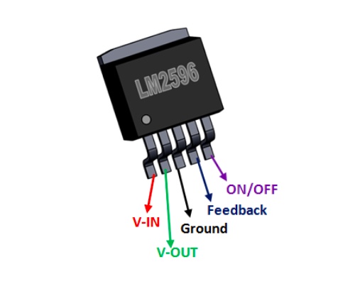
This is the mosphet on board
It has an on/off pin
I'm assuming that's the sw pin on the board maybe?
And on the scemantic it just says this pin needs to be grounded
I just found this I'm not sure if I'm right
I just tested the sw pin on the board to the on/off pin on the mosphet using the beeper mode on my multimeter and got silence
terse lagoon
Ok so buck starts on with just +- wired nothing on sw and while it is on shorting sw to ground does nothing @worldly schooner
I was thinking of trying positive next on the input side since it's closer to that but I'm worried
supple pollen
terse lagoon
This is the mosphet on board
That's not a MOSFET, that's a switching control chip
terse lagoon
Oh my bad they look fairly similar
I decided to just put the switch on the input and forego the internal switch anyway could figure it out
 kindred kernel
how difficult is it to pair down the playground circuit express to just components that are needed for a specific project? i only need power in (battery or usb would be fine), the microphone, light sensor, maybe a smaller controller(?) and the leds
would it be cost effective or maybe not save that much in the end
supple pollen
kindred kernel
how difficult is it to pair down the playground circuit express to just componen...
It's simple enough to remove components, if you want to shrink/reshape the board, it may be a little effort rerouting traces. I'm not sure what the cost breakdown is like, I suspect if you're having it assembled, the assembly costs would dominate, but if you're putting it together yourself, saving money on components and possible board space would be nice.
idle python
i have a YX350HV15-T display and i want to use it with a radxa computer, but spi is too slow, and the chip on the radxa does not support DPI.
is there some sort of RGB to hdmi IC chip i can buy?
kindred kernel
that's a good point, i'm also really unsure about the little things between the components resistors, capacitors, etc, thanks @supple pollen
supple pollen
Usually the schematic shows the support components near whatever they're supporting, but it does sometimes take some thinking to determine which parts are necessary under different situations.
idle python
@supple pollen do you know where i would find more information about this display number YX350HV15-T? cant find anywhere on google
supple pollen
idle python
<@348911944486486016> do you know where i would find more information about this...
Usually I look up the LCD panel inside the display on panelook.com
fervent lance
Would the BLM3401 mosfet be good to use as a reverse-polarity protection transistor?
14-7v input power
https://datasheet.lcsc.com/lcsc/1810221832_BL-Shanghai-Belling-BLM3401_C90479.pdf

.120 ohms Rds(on),+-20v gate-source drain, -30v drain-source voltage
https://www.youtube.com/watch?v=IrB-FPcv1Dc
Based on this video, it should be pretty good for it. 1.5A max input power
I just want another set of eyes since this is my first time adding a protection circuit
How to use diodes, schottky diodes and P-FETs to protect your circuits from reversed voltage/power connections.
Website: http://www.afrotechmods.com/
spice turtle
I dont see any issue with it
But, if you want to experiment first, Id get the equivalent through hole FET and bread board it so you can test it
I personally do that when possible with new circuits, or a new idea. Other times i just throw it at a wall and see if it sticks lol.
the only thing I would suggest is to try to find a fet with a lower RDS that fits in your budget
I would also go with something with a slightly higher VGS breakdown. Its not close, but if your 14V supply goes over too much you can fry the fet.
(you could also add in a zener)
 granite steppe
Hello,
I have a p-channel MOSFET with Vgs threshold of -2.9V . With my Source voltage of 5.14V, I understand I cannot directly use a 3.3V from an STM32 to turn the PMOS fully on (3.3V - 5.14V = -1.84V > -2.9V). Hence I use the n-channel MOSFET BSS138 with Vgs threshold of 1.3V as in the above figure. My questions are:
- Will the circuit work, or do I need to know/specify any more parameters?
- I've used the Schottky diode to ensure that if the manual switch SW1 grounds the PMOS_G line, turning on the NMOS should not short Vpp and GND. I understand that with 150kΩ R15, I'll not lose any much current, yet it seems safer to have the diode. Are there any downsides to using the diode?
- I've used a 1.24kΩ resistor for the NMOS gate. Will it be appropriate?
- Should I add a Rgs resistor for NMOS Gate and grounded source? How should I select its value?
- Vpp goes up to 5A @ 5.14 V, should I be concerned about Miller capacitance for the two MOSFETS? If so, how can I tackle it to achieve quick turn on and small shutdown time?
If I need to provide any more information, do let me know.
Thanks in advance.
 signal topaz
granite steppe
Hello,
I have a p-channel MOSFET with Vgs threshold of -2.9V . With my Sourc...
signal topaz
granite steppe
Hello,
I have a p-channel MOSFET with Vgs threshold of -2.9V . With my Sourc...
You could add a pull-down resistor at POWER_PIN. Just to avoid unintended turn-on, when pin will be not driven for some reasons. I would expect R11 to be smaller, in ohm range, e.g. 100.
granite steppe
signal topaz
You could add a pull-down resistor at POWER_PIN. Just to avoid unintended turn-o...
Thanks for your reply.
I'm using 1.24k ohms for R11 because I'm using it elsewhere on my design.
I'll definitely go smaller.
Do you have any recommendations for pulldown resistor value for the POWER_PIN?
signal topaz
like 10k-100k
In my opinion this schottky might be an overkill but it should work. I wonder if switch can cause some problems. It can cause some bouncing and switching of U4.
granite steppe
I have a ~130k resistor in my design elsewhere which I can reuse for Rgs.
I usually add a capacitor across switch inputs to curb debouncing*, but in this case that feels dangerous because it will increase capacitance on gate of the PMOS effective on and off timings 😦
signal topaz
granite steppe
I have a ~130k resistor in my design elsewhere which I can reuse for Rgs.
I u...
what is your load on VDC?
Tou can also add a ceramic capacitor on VPP close to U4 (1-10uF). Or at least add a placeholder.
granite steppe
signal topaz
what is your load on VDC?
It is supposed to drive a Raspberry Pi at 3A, though Vpp is designed to supply up to 5A.
Edit: To add, I'll probably be adding a fuse of trip current 4.6A beyond VDC. It depends on if I have any real state left on the PCB.
Edit to the Edit: choosing a fuse of 4.6A trip current might not be the best choice. I'll get back on that later.
fervent lance
I have a buck converter that takes 12v and creates a 5v and 3v supply for LEDs and an RP2040.
When I plug it into USB, how should I route the VBUS power? Is it okay to just connect it to 5v? Should I connect it to Vin?
fervent lance
So I read I should definitely not connect VBUS and 5v, but I don't know how I would connect the USB to power the board
 eternal fox
I love to learn new things, however i have many projects and little time. Does anyone know how long it would take to learn how to do PCB design and create a functioning 6port USB 2.0 hub? Or should i just pay someone to do it?
ONE of my projects is to rehash an existing ortho keeb layout to include space for the above mentioned USB-hub, one MCU to deal with the keeb, rotary controllers x2 and a small i2c display and one mcu (pi pico) to do wireless work.
The idea is that the hub should have 2 open ports for peripherals like a logitech unifying reciever and one more small and low power peripherals as well as 1 data and power port to the host device, a secondary power port (for easy power injection) and two ports that are hidden from view and used to hook up the keyboards mcu and the pi pico or whatever extra mcu i decide to use (hidden under the keeb).
I've tried to use an online pcb tool and it seems simple enough and i guess i could post the design to some forum and ask for input/validation but im sure il go through at least 10 iterations without getting very far.
What would you guys and gals do if you were in my shoes?
supple pollen
eternal fox
I love to learn new things, however i have many projects and little time. Does a...
Learning basic PCB design can be done in weeks. USB, however, is a little demanding, and might take some more time (USB 2 is reasonably robust and you might get away with it). As for what I would do, that's pretty simple: I'd buy an inexpensive, compact USB hub, strip it out of its enclosure and just embed that board inside my project.
eternal fox
supple pollen
Learning basic PCB design can be done in weeks. USB, however, is a little deman...
Yes i did just that but the hub failed quite quickly (really thin pcb and ... questionable chineese quality). The issue is trying to find a hub that is small enough and has the correct layout imo. Id need one or two south-wards port (or west), one or two north-facing and two to the east whilst still being a small package. Anything that you've come across?
supple pollen
That is a tricky one. Usually when I want specific port orientation, I have internal short USB adapters or patch cables, but if your enclosure is small, there may not be room for that stuff. USB hubs, at least, are fairly simple boards, the meat of them is the pairs of differential USB data lines, which should be approximately equal lengths and of reasonable impedance. And as this blog entry points out, USB is pretty robust, if it drops a packet, it'll just retransmit it. https://www.sparkfun.com/news/2561 Might be worth a try.
 hasty solar
Hey, first time here and I’ve got what I think is an easy question! I’ve got a couple of QT PY’s on order, a couple of I2C based sensors and also an SPI oled display.. my first question is, will I be able to connect I2C sensors and an SPI display to the QT PY? My second question is how could I find the answer for myself 😁 thanks!
worldly schooner
hasty solar
Hey, first time here and I’ve got what I think is an easy question! I’ve got a c...
- Yes, assuming you have the tools to solder the needed headers or wires for the SPI connections.
- Short answer: if you look at the pinout in the learn guide and have enough pins for it, you’re likely safe.
Long answer: if your I2C sensors can all share a single bus, as in common clock speed, no address conflicts, etc. your I2C devices should be fine with the two pins and/or the stemma connector. Some qtpy varieties have two separate I2C buses, but you will be able to see that on the pinout diagram in Adafruit’s learn guide. SPI devices may share MOSI/MISO/SCK, but will each need their own CS pin. Generally, combining this knowledge with the pins available is enough for most applications, but there’s also more detailed information available in the learn guides’ downloads pages, where you can find chip data sheets, board schematics, and more.
hasty solar
worldly schooner
1) Yes, assuming you have the tools to solder the needed headers or wires for th...
That’s great, thanks. Discovered I will have an I2C address conflict and also doesn’t appear there are any solder pads to change it either on either of the sensors.. no way around this I assume?
The thing that has me confused now is that the oled (ADA5206) is described as using ‘4-wire SPI’ but then proceeds to have 10 pins listed, which would very nearly I think use all the remaining pins on the QT PY.. it is a small board though I guess! More reading around the oled to do I think
eternal fox
It is, i've been scouring tons of sites to find just about anything even close to it and its all either the wrong orientation, "badly" shaped units or odd quirks added into them.
Was thinking of routing some either flat cables or small cables and hook them up to the two "internal" usb-ports. Could possibly be done quite nicely.
worldly schooner
hasty solar
That’s great, thanks. Discovered I will have an I2C address conflict and also do...
Which qtpy are you using? If you’re not using the M0, the stemmaQT and header pins offer two separate I2C buses to separate a single I2C conflict. Otherwise, there is an I2C multiplexer option in the pca9548/tca9548.
hasty solar
worldly schooner
Which qtpy are you using? If you’re not using the M0, the stemmaQT and header pi...
Just using the basic one with stemmaqt adafru.it/4600
The pin out looks like the pins and the stemmaqt port are the same PIN numbers so assumed can’t use both at same time
It is the M0 one I believe
worldly schooner
@hasty solar as for the display you’re looking at, you don’t need all of the pins for the display to work. The power pins can be shared, and many of the other pins can be excluded in some simpler display applications.
It does look like you’ll want to have a CS and DC pin, but RST and BL can be left unconnected if you don’t need those controls.
worldly schooner
eternal fox
It is, i've been scouring tons of sites to find just about anything even close t...
Is 2.0 a requirement for all ports? A 1.1 hub design can be made fairly simply, and the speeds are low enough that you won’t need super tight length matching.
That being said, most hub chips tend to be 4 port, so it may require multiple hubs, or simply multiple ports.
eternal fox
worldly schooner
Is 2.0 a requirement for all ports? A 1.1 hub design can be made fairly simply, ...
Well, i dont know if 2.0 is strictly needed but i think id like to keep it to that, thank you for suggesting an alternative, thats always appriciated and il keep it in mind 🙂
I think i've found a few ic's that can handle up to 7 ports and i assume (most likely wrongly) that the main difference is a lower per port availible power draw as well as a lower per port data speed because it shares that one USB line, right?
I also assume that its much like a 4 port but that i just place 3 more ports on the pcb... Biggest issue i think il have will be the design, i assume that the basic firmware is pre-loaded onto the ic... or am i sorely mistaken?
supple pollen
eternal fox
Well, i dont know if 2.0 is strictly needed but i think id like to keep it to th...
Generally the ICs handle the data, not the power.
worldly schooner
Many hub ICs don’t actually handle any power at all. Data is shared, so it is possible some ports will have a lower speed.
All of the hub logic is usually baked into the IC. Generally application-specific chips don’t require programming.
supple pollen
I haven't looked recently, but when I did previously, the 4-port chips were really common and the others were much less so. I strongly suspect the 7-port chips are just two 4-port chips internally anyway (with the second chip connected to one of the ports on the first chip). You can do the same thing on your board if you have trouble obtaining 7-port chips.
worldly schooner
I think microchip has a bunch of 6-port options, actually. Most of the newer ones assume a usb-C input, but split off into at least 4 high-speed ports if not all 6.
7-port chips are probably 6 downstream, one upstream…
They’re not the easiest to design with, so ideally some experience or extensive research on USB design is recommended
Expect it to take a couple of iterations to get perfect?
eternal fox
Okay, so for the power i just let the USB controller host side deal with power or will it simply just provide 5v xA and then let the downstream device pull what they want?
eternal fox
supple pollen
I haven't looked recently, but when I did previously, the 4-port chips were real...
Sounds like a plan!
worldly schooner
Most actual usb hubs have separate chips to check for overcurrent on individual ports, which you probably won’t need for the internal ones.
Take a look at the schematic for EVB-USB2517 as reference?
Or 2514, should be the same design with fewer ports…
eternal fox
worldly schooner
Expect it to take a couple of iterations to get perfect?
Yeah... thats another one... The usb-c port... Obviously il create the pcb with SMD in mind and have it pre soldered at the factory... but all those pins.. scary stuff.... Have to study that connector properly.
worldly schooner
Usb2517 is 2.0, so none of the type-c struggles.
eternal fox
Il absolutely take a look at those chips, thank you very much!
Btw, any pcb-designing software you'd recommend?
worldly schooner
I think I’ve been recommending kicad to everyone, as it is and likely will stay free, and is among the best within that category of EDA tools.
EasyEDA isn’t bad either if you plan on getting fabs from JLC?
eternal fox
Great suggestions!
Dont know whom il source the pcb's from tbh. No matter what, if i do some pcb designs il probably get the hang of it and be able to make something nice in a few years or so 😛
Honestly dont know what fab is The one to choose. Just know that id love the keyboard pcb to be made with some exposed traces and a black dye, dont know what all of it is called but i guess thats what would limit what fab i choose.
That and cost obviously.
supple pollen
If you want to keep flexibility as to which fab house to choose, you'll want a package that can produce standard files then. KiCAD can do this, as well as most of the commercial non-free packages.
worldly schooner
Oh, sorry. Fab is just what my company calls bare unassembled PCBs. Short for fabrication.
supple pollen
Several board houses can offer different colors of soldermask (I tend to get my odd colored boards from PCBGoGo and CircuitHub, but there are plenty of options)
eternal fox
worldly schooner
Oh, sorry. Fab is just what my company calls bare unassembled PCBs. Short for fa...
Yeah im 100% NOT an experienced member of this community haha, sorry for usign the wrong terminology and thank you for the correction 🙂
worldly schooner
Please don’t be, you’re not even wrong
eternal fox
supple pollen
Several board houses can offer different colors of soldermask (I tend to get my ...
Great, then I take a look at kicad and shop around for pcb manufacturers, i mean prototypes dont need to be flashy (they do however always require LED's 😛 )
worldly schooner
Many ways to reference the same thing, and I’m still learning a lot of them myself…
eternal fox
Well, i guess thats true, just easier if i use the same terminology, that way you'll understand what im wrong about at least haha
Thanks to both of you, really gave me a great starting platform to build my ideas on ❤️
supple pollen
We all start out as beginners and I always like seeing more people wanting to learn, try stuff, and build things
eternal fox
Btw, one last question: Trace width: Whats the recommended width of power traces and is there a formula or rule of thumb i can follow as to not bleed power or restrict it in some weird ways?
eternal fox
supple pollen
We all start out as beginners and I always like seeing more people wanting to le...
So true!
supple pollen
Trace width depends on a few things, but for power delivery, it's basically to control resistance to current flow: for more current, you want a wider trace. A too-narrow trace for a given amount of current will act as a resistor, dissipating power, which means less voltage is available at the far end, and (in more extreme cases) the trace itself will overheat and melt (basically acting as a fuse)
Technically all traces act as resistors, but my approach is to keep them thick enough that the resistance doesn't become a problem.
For most of my boards, I use 10 mil traces for most things, and thicker ones (or planes) for power.
eternal fox
Nice! Thanks again for such good help! ❤️
idle python
anyone know a 3.5 inch panel with mipi dsi support and capacitive/resistive touch screen and ideally compatible with the raspi (just wire the 4 mipi dsi channel pins to the pi display connector and youre good to go), i dont want big expensive ICs to drive the screen
supple pollen
For a screen that small, you may have more luck finding an SPI interface
worldly schooner
idle python
anyone know a 3.5 inch panel with mipi dsi support and capacitive/resistive touc...
DSI displays typically start at 5 or 7 inches? 3.5” screens would usually be driven by the GPIO header, either manually wired or in a HAT form factor.
worldly schooner
idle python
anyone know a 3.5 inch panel with mipi dsi support and capacitive/resistive touc...

OSOYOO.Store
This 3.5" DSI screen for Raspberry Pi comes from customer returning order.The quality and functionality is exactly same as original OSOYOO 3.5" DSI screen. You will save 30% from original price. The detail of the original product is as following: PROFESSIONAL RASPBERRY PI MONITOR ---- Raspberry Pi hobbyist could not mi
supple pollen
Wow, good find!
worldly schooner
I am genuinely surprised to find this exists.
I don’t think these are still being made, but what the heck do I know
idle python
worldly schooner
https://osoyoo.store/products/osoyoo-3-5-inch-dsi-touchscreen-lcd-display-for-ra...
nevermind that is literally the thickness of a photo frame
i guess ill just deal with a hdmi to rgb bridge ic
worldly schooner
Thickness? Is that including the Pi itself and the DSI cable wraping all the way around?
idle python
meant the thickness of the borders
it makes sense why its there though need space for backlight
worldly schooner
Are you trying to fit this within a certain space?
worldly schooner
And you need access to the GPIO header?
idle python
well i have a cm4 and im making my own carrier board soo
the display wont be on top of the carrier board
more like a laptop
worldly schooner
2.8inch Capacitive Touch Display For Raspberry Pi, 480×640, DSI Interface, IPS, Optical Bonding Screen | 2.8inch DSI LCD
idle python
i have this hx8357d display that says i can change the interface mode to mipi dsi but thats only for hx8357d01
idle python
worldly schooner
https://www.waveshare.com/2.8inch-dsi-lcd.htm
oh yea i was just looking at this, i wonder what model that panel is
worldly schooner

UCTRONICS 3.5 Inch Touch Screen for Raspberry Pi 4, HDMI TFT LCD Mini Display with Stylus Pen for Pi 4 B, 3 B+
idle python
@worldly schooner that screen waveshare uses is actually a rgb screen

the chip included on it is a mipi dsi to rgb chip
and i have a rgb screen
soo i think i might just buy this chip and put it on a pcb
eternal fox
Speaking of screens, anyone has any experience using the ultra wide "7.9 waveshare screen (or anything similar)?

Waveshare Raspberry Pi 7.9inch Capacitive LCD HDMI Display 400×1280 Resolution IPS Touch Screen with Toughened Glass Cover Supports All Versions of Raspberry Pi Jetson Nano Windows 11/10/8.1/8 /7
fervent lance
~~kicad is really confusing me
if I don't apply the solder mask, then the render will show me a solder mask
if I apply the solder mask, then the render will show me solder mask being removed
but in reality under the fab the solder mask will be applied, so if in the render the dolder mask is removed, it will be applied on the pcb, otherwise not
this is due to the processing method of the fab as I did understood
but as an user that will use a pcb manufacturing service, why do I need to deal with this extra confusion? ~~ nvm I was in the wrong layer for this section
then if I apply a zone that's without copper, it looks like I can't see it on the pcb render
what do I even need a render if this doesn't display the end product?
spice turtle
Another PSA/FYI: Triacs have a polarity. The "supply" side is opposite of the gate, so MT2 (most common name) is your "hot" lead, while MT1 is your neutral.
Found this out the hardway, aka "why wont my Triac trigger?"
Take a look at this schematic: The bottom one works (tested and verified). Top one? Its the wrong way around.
 supple pollen
I generally regard them like other semiconductors and figure the gate lead input is referenced to one of the MT leads (generally MT1), similarly to how a MOSFET's gate is referenced to the source. Triacs are generally specified in four "quadrants", combinations of the polarity of voltage between MT1 and MT2, and between gate and MT1. The "four quadrant" triacs can trigger on any combination (but are generally more sensitive in some quadrants than others).
spice turtle
Hmm. I had suspected that it should work, but the only differences Ive found was that MT1 and Mt2 were swapped. It is possible I gave the gate too much current and I now have a dead triac, but testing can rule that out (which Im about to do)
I could be wrong too 🙂
supple pollen
It could be that we agree and we're just using different terminology
spice turtle
So, MT2 (or T2) is the Pin opposite of the gate. MT1 (or T1), is the pin closest (or parallel to) the gate.
It does seem that the datasheet lists T2 for the main spec for all the tests rather than T1. So I think I do have it backwards
ie:

 spare galleon
is this implementation correct from reading the document?


 spice turtle
Looks good on my end
BTW, use these flag things:
It makes it easier to read 😄

(just a small tip)
limpid nest
I want to do the following: use panel mount connectors that connect to cables but also have solder connections on the other side to connect to a board so that my board can be mounted on the wall of an enclosure. Is this something I can do?
supple pollen
limpid nest
I want to do the following: use panel mount connectors that connect to cables bu...
It can be hard to get the mechanical bits to align, but yes, such connectors exist.
limpid nest
Do they have a specific name?
supple pollen
I guess you'd select "panel mount" as the style and something like "PCB pins" or "solder tail" for termination
woven bluff
are there compact PIR modules with adjustable sensitivity?
all digital output PIR sensors seem to be unable to ad just sensitivity
inland jungle
supple pollen
I guess you'd select "panel mount" as the style and something like "PCB pins" or...
In the past, I've turned a DB solder cup connector into a panel mount -> PCB connector by fitting the PCB inbetween the solder cup rows and soldering to pads.
 manic magnet
Hi, I've been asking around all over the place and slowly improving my schematic and PCB design. Anyone have some positive criticism to share with me?


(beware I'm not that smart and I don't know much about the PSU part)
supple pollen
inland jungle
In the past, I've turned a DB solder cup connector into a panel mount -> PCB con...
Yeah, I've seen that done, it fits pretty nicely with the usual 1.6mm thick PCBs. I've also seen that done with dual row header, and SMA connectors.
supple pollen
manic magnet
I would suggest adding spike suppression diodes across the relay coils to protect the MOSFETs from inductive spikes when the coils are switched off.

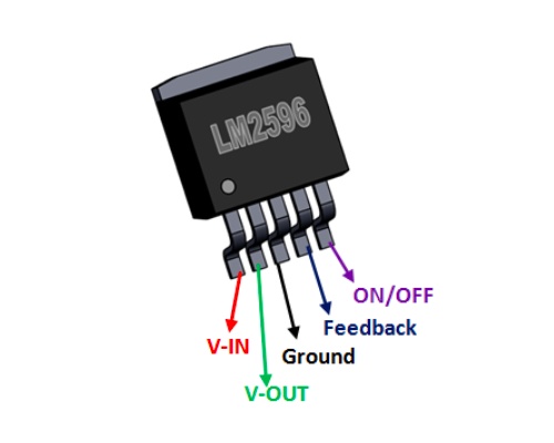 supple pollen
Ah, that's handy
manic magnet
That's why I chose them
their typical applications diagram is 3 wires, no other components
and thats very useful when you're a novice
So do you see any glaring mistakes or something like that?
heavy jasper
The relay diagram isn’t the most clear to me - in particular the arrangement of the switching contexts. It seems like it’s an SPDT relay - but which is the common pin? I think it’s pin 4, but that relies on really zooming in to see the line coming from it going just beyond the contact line on pin 3. And in this case it doesn’t look like it could really reach pin 5, so maybe it’s coming from pin 3 after all?
Pin naming (e.g. COM, NC, NO) instead of just numbers would help a lot, as could some more clear drawing, e.g. something like:
 manic magnet
Yes I think I should do that, this is just the standard naming from the lcsc package
4 is common, 3 is NC and 5 is NO
And I'm using NC as a resistance measurement of the attached load
woven bluff
is it a good idea to put ground trace between two pads of a SMPS inductor?
manic magnet
I don't know tbh
supple pollen
woven bluff
is it a good idea to put ground trace between two pads of a SMPS inductor?
That's a good question. It will tend to couple noise to ground, which might be good (because that noise is less likely to go elsewhere) or bad (because your ground will be more noisy).
manic magnet
I have no clue which would be better to be quite honest
woven bluff
can I use 3v3 to feed a 3v2 LDO?
supple pollen
woven bluff
can I use 3v3 to feed a 3v2 LDO?
You can, but even for an LDO, that will be below the dropout voltage, so you wouldn't get a regulated 3.2V out of it.
heavy jasper
There are some LDOs with ultra-ultra low dropouts, depending on how much current you need
e.g. I think this one from TI would work: https://www.ti.com/lit/ds/symlink/tps731.pdf
distant raven
heavy jasper
There are some LDOs with ultra-ultra low dropouts, depending on how much current...
This is good to know, I wasn’t aware of these before
Actually turns out I was using a variety of it, the TPS73201
heavy jasper
And actually - I take back that recommendation for the TPS731
Not because of the low-dropout-ness
but because of this:

They are not kidding about the overshoot
I had a 5Vin, 3.3Vout LDO overshoot to 4.3V at startup; though I think in my case it was with a fast input turn-on, since the pass gate would slew to follow the input, then get crashed down by the LDO controller coming fully online.
Which eventually caused voltage overstress failures in some downstream microcontrollers after enough board power cycles
I would not recommend using this part unless you can have its enable line pulled default-low, and have some upstream programmable element (MCU, power sequencing controller, etc) to drive it high when you need it
woven bluff
can you use one tactile button to power on-off without using ACPI chip?
input load switch, enable pin pulled down, one tactile button connect the enable pin to a stronger pull-up, as the same time connected to MCU, when MCU detect long press, it drives down the pin
will this work?
 woven bluff
humm, found an IC does that MAX16150
sharp notch
I am trying to understand better this part of a schematic, I think I understand the mosfet wiring part, but what I don't get is the P03 connection to the diode that is connected also to power. I wonder if it could be an error in the published schematic, or what the magic is here--I feel like the way its wired, if the diode opens up, wouldn't it be shorting ground and power?

PUMP3 is a logic controlled gate from a pico, and the J7 connects to a small DC pump motor. P03 is the part that confuses me.
supple pollen
sharp notch
I am trying to understand better this part of a schematic, I think I understand ...
I don't know what PO3 connects to, but I'll often see diode protection wired like that to divert voltage spikes that rise above the supply voltage. I'm not sure what you mean by "the diode opens up", or how it would be shorting ground and power (but again, I don't know where PO3 goes).
sharp notch
P03 is wired from that anode of the diode to the wire that connects the ground of the pump motor to the mosfet drain. If I ignore the P03 connection to the diode, it makes sense to me that when PUMP3 turns on, the switch opens a patch to ground and allows current to flow through the pump. But its that connection between the P03 from the mosfet drain to the diode that is confusing me, because I am not sure I understand when that diode would be open vs closed.
supple pollen
sharp notch
P03 is wired from that anode of the diode to the wire that connects the ground o...
Ah, now I see the PO3 callout on the MOSFET drain. I'm going to sidestep the "open" and "closed" words, as they're confusing (a door is considered "open" when a person can pass through it, but in electronics, "open" tends to signify the opposite: in an open switch, current cannot flow). So under normal conditions, PO3 would be less than or equal to the supply voltage, and the diode would not conduct. But if a voltage spike occurs that's more than the supply voltage, the diode will conduct it to the supply rail.
sharp notch
Interesting, thanks @supple pollen that makes a lot more sense to me now. So because the voltage is greater than the supply voltage when the diode is in conducting mode, it will conduct it to the supply rail -- does that mean that the PI_5V signal would go higher than 5V temporarily during that spike, or how does that work out?
supple pollen
I can only guess here, but my guess is that the pump is an inductive load, so when it's switched off, its magnetic field collapses and generates a voltage spike. Personally, I prefer to connect the diode differently, but I've seen the diode to the power supply hookup used before.
sharp notch
Yeah, its a wound coil magnetic induced pump.
spice zenith
Just want to confirm something before I solder it all up. I'm dealing with LiPo batteries, so I have a very healthy respect for them, and want to be 100% certain about what I'm doing. I have one of these that I plan to use as a UPS for a Raspberry Pi: https://www.adafruit.com/product/2465 connected to one of Adafruit's 1200 Mah LiPo batteries.
I notice that there's an edge connector on the side of the board, and I want to check that I can use that instead of the two USB connectors. In particular, three connectors caught my attention: 5Vo GND and USB. Am I correct in thinking that these are the output voltage to the RPi, ground and supply voltage from my wall wart respectively, and I can just solder directly to these rather than having to butcher a USB cable to feed power into this?

PowerBoost 1000C is the perfect power supply for your portable project! With a built-in load-sharing battery charger circuit, you'll be able to keep your power-hungry project ...