#help-with-hw-design
1 messages · Page 4 of 1
 limpid nest
 unreal flax
limpid nest
What's worse for a PCB: smaller power/gnd pours that aren't interrupted or large...
unreal flax
limpid nest
What's worse for a PCB: smaller power/gnd pours that aren't interrupted or large...
Hard to say in general. You could think of the smaller pours as pieces of a hypothetical larger pour with big interruptions between the pieces, for example. Some interruptions can have minimal effect and others cause big deviations of return paths.
limpid nest
Yeah it's hard for me to put a rule on but I thought there might be one
I'll just focus on trying to make big pours without interruptions
 knotty tiger
much like in other parts of engineering, "it depends". i think there are broad guidelines about where interrupted pours might get you intro trouble, like where there might be high current flows, or where they're joined with a long trace that has enough inductance to disrupt the circuit
 supple pollen
For high current/high frequency, interruptions are to be avoided. But if you're using the ground pours for heatsinking, larger is better. In cases of both, you tend to end up with lots of via stitching
 woven bluff
OK, CCFL Inverters have high ratio transformers
they are a bit bulky, but much better than CRT transformer
supple pollen
Yeah, they're good to 1300V or so which is useful. There are also high ratio transformers available from surplus vendors, places like Information Unlimited, and the far East (such as the popular MP-2057). I have links if you're curious.
 pale umbra
is it a good reflex to be scared when a transformer start ringing/whining loudly and shut off the power going to the appliance it's in ?
woven bluff
no, transformers whine alot
limpid nest
Yeah it's part of how they work/a consequence of materials
pale umbra
what about ringing and the appliance display lcd goes wacky and randomly displaying things turning on/off?
knotty tiger
sometimes switching power supplies will audibly squeal when overloaded
the sound in combination with unusual behavior of the device it's powering does suggest some kind of fault condition, which could become hazardous depending on the details of the device
pale umbra
yeah its fuse was turned off and they came and unplugged it inside the wall but was a bit scary
but I'm pretty sure the ringing was a feature, as in it was probably not the transfer but the control board having a speaker/ringer
 carmine plume
hey i've got a pcb with pads for a 2.54mm 2-pin header - any suggestions for a good low profile header?
 distant raven
knotty tiger
sometimes switching power supplies will audibly squeal when overloaded
distant raven
knotty tiger
sometimes switching power supplies will audibly squeal when overloaded
I also audibly squeal when under pressure
pale umbra
I just sigh loudly and yawn like a lower-pitch chewbacca
supple pollen
carmine plume
hey i've got a pcb with pads for a 2.54mm 2-pin header - any suggestions for a g...
Male or female? There's this for short male pins: https://www.adafruit.com/product/4173

These three Short Male Headers alone are, well, lonely. But pair them with our ItsyBitsy boards, and you're in business!These 2.54mm / 0.1" pitch headers ...
carmine plume
I think I might try and go for a low profile jst connector at right angles
really any low profile 2.54mm connector will do
pale umbra
is there something that can sort of analyze PWM if all else fails for my R/C stuff ?
to trace how it arm (duration/baud rate/etc)
supple pollen
The traditional tools are things like logic analyzers and oscilloscopes, but you can also use stuff like a "pulse in" function available on many microcontrollers
pale umbra
are they going to be fast enough for something that last like 1us at 115000 bauds ?
unreal flax
These sorts of cheap USB logic analyzers are pretty good bang for the buck: https://www.sparkfun.com/products/18627

This 8-channel USB Logic Analyzer with support for sampling rates of up to 24MHz provides a good while economic option making it a great and easy tool.
pale umbra
it's not usb though but custom connectors like XT60, mini-tamiya etc
unreal flax
No, I mean the logic analyzer hooks up to your PC via USB. It just has wire leads to attach to whatever you're analyzing.
pale umbra
the reason I haven't gotten an ESC yet is this and because it's hard to tell if the ESC allow for expansion and the connections aren't soldered also all those new connectors (ESC normally need to be connected to the lipoly battery with the same connectors that the receiver use) and bigger connectors are used for bigger loads just like lower AWG are used for bigger loads
supple pollen
I don't know what you mean by "allow for expansion": most ESCs have fixed programming, but some have the ability to configure various parameters. You could always splice wire or solder new stuff on, but most of them come with wires attached already. Normally the ESC powers the receiver with its on-board regulator, but some builds use a UBEC to power the receiver separately.
 pale umbra
supple pollen
I don't know what you mean by "allow for expansion": most ESCs have fixed progr...
pale umbra
supple pollen
I don't know what you mean by "allow for expansion": most ESCs have fixed progr...
well this one clearly doesn't allow for expansion, no free female connectors terminals on it, I cannot hook an arduino on those terminals since they are there, limit what kind of battery etc I can use etc + they are soldered so it force me to use specific type of connector

whereas a traxxas xl-5 is expendable but very expensive as well so trying to find a modular one in the 40$ range
the 1/64 esc are the worst as everything is used
supple pollen
I still don't know what you mean by "allow for expansion" or what female connectors you want. You can hook an Arduino to the control connection. As for battery connectors, you can use adapters or just cut off the provided connector and replace it (I've standardized on Anderson PowerPole connectors for my builds, so I install them on all my batteries and ESCs)
Here's one of my Traxxas models, I've replaced the Traxxas battery connector with my usual PowerPole
 pale umbra
well in the case of this one I can't put a 2nd battery
it has 3 free wires and 1 battery wire
supple pollen
Why would you want a second battery?
pale umbra
because Im doing 1:10 and those are pretty powerful
and the battery will be quickly used (between 9 and 39 minutes)
supple pollen
You could either use a bigger battery, or (carefully with proper precautions) parallel batteries, or use a series connection if the resulting voltage is something the ESC can accept.
I do have a pair of paralleled 105Ah AGM batteries, but that's not for a vehicle
pale umbra
I guess I'll go for the build I said the other day or wait until I have enough money for the SCX10
it comes with an esc and a receiver/transmitter so it would be kinda useless to buy an esc now just to test if I can interface with one than throw it if I get the scx10...
Well 105Ah sounds suitable for bigger vehicles
like scooters or forklifts
pale umbra
supple pollen
I still don't know what you mean by "allow for expansion" or what female connect...
well basically I'll admit I don't know if I'll need expansions if I add shield or an rpi etc.. it's going to be a costly mistake if I can't
so I'd rather have too much than not enough...
 void sentinel
Is that a three phase rc car?
sounds efficient. I never thought of applying that to smaller motors. We have been using vfds for decades.
pale umbra
3 phase motors have been used for a long time in the r/c world
they are just so far ahead of the general electronics community for motors/mechanics - the best you can get is a terrestial 70$ motor that's like 10W in general electronics while these can go up to ~1400W in burst (120A ESC * 12.2V) and you also don't have to create the mechanical system for a robot etc
also saw an high-end 12000$ semi-open robot that uses an r/c as the mover
all they did was reinforce the wheels and shocks
void sentinel
Um, ping moderators? what is the proper reaction to this?
(besides reposting it in a way that defeats bot scripts?)
More importantly, what was the bad word? The f word?

Futaba?
nope...
must be methane
weird
Ok my newest edit. Can I just post the brd files or is that more complicated than a screenshot if it has to be downloaded and ran in special software? Hmmm.
 pale umbra
it mention something dangerous / discord product that's why it's blocked - at least that is what I was told
code of conduct mention "Discussion or promotion of activities or projects that intend or pose a risk of significant harm" and that word would fall in it
void sentinel
the n i t r o?
pale umbra
You could ask in #help-with-community if my hypothesis doesn't answer your question

 woven bluff
pale umbra
code of conduct mention "Discussion or promotion of activities or projects that ...
woven bluff
pale umbra
code of conduct mention "Discussion or promotion of activities or projects that ...
discord snow flake
 vast flume
Hey guys, posted this to the general channel but meant to post here

Accidentally had my microusb port flipped on my pcb
Any ideas on how I can surgery this back to life? 🤣
knotty tiger
oh, is the receptacle opening facing away from the edge of the board?
limpid nest
Yeah, only thing I can think of is using a R angle piece
vast flume
knotty tiger
oh, is the receptacle opening facing away from the edge of the board?
Yeah
knotty tiger
vast flume
Yeah
so if you rotated it 180 degrees in the plane, you'd have to swap all the wires (and the stakes would be in the wrong place)?
vast flume
knotty tiger
so if you rotated it 180 degrees in the plane, you'd have to swap all the wires ...
Yup, pretty sure
I think what happened was the datasheet wasn't clear with which orientation the port was supposed to be in
So I didn't know which way to orient the footprint
pale umbra
PCB Maker "so user has made error I think they have a usb plug pointing into the board" - not my job print it anyway
limpid nest
JLC at least does some error checking, as I've gotten feedback from them before, but I doubt they'd go as far as that
Your board, your error.
Having made a number of them, I feel the pain
vast flume
Yeah they actually asked me about the component placement for other components on the board, but not for the single most important thing that I cant fix myself with reworking 🤣
limpid nest
Ouch! Sorry friend
 hollow flame
any tips for making wire to board connectors? harnesses s i've heard them called. is there a particular molex series thats easiest to crimp? I'm very comfortable doing things like crimping RJ45, is there anything that would be kinda smilar to that?
 tough matrix
hollow flame
any tips for making wire to board connectors? harnesses s i've heard them called...
tough matrix
hollow flame
any tips for making wire to board connectors? harnesses s i've heard them called...
buy premade cables! they save you a lot of pain
do you need something very specific?
hollow flame
I need to route the individual wires to very different places, but I want a clean connection on the board just cause I think it looks more professional. I've used screw terminals in the past
tough matrix
if you have freedom to choose your own connectors to place on board, choose something like JST PH connector on the board and then buy cables like this one

This cable will let you turn a JST PH 4-pin cable port into 4 individual wires with high-quality 0.1" female sockets on the end. We're carrying these to match up with any of our ...
how much current do you need to carry?
hollow flame
its just 5v logic im basically just running it to different potentiometers
 rustic fulcrum
hollow flame
its just 5v logic im basically just running it to different potentiometers
rustic fulcrum
hollow flame
its just 5v logic im basically just running it to different potentiometers
I guess alongside buying pre-made cables, which is probably easiest, my core recommendation is to use silicone wires for flexibility, heat resistance, and better environmental..ness.
That said, I did stumble on a huge guide to this a while ago, let's see if I can find it
Not sure how pricey these would be but:
https://www.youtube.com/watch?v=BkWZDL3xorg
https://www.digikey.co.uk/en/product-highlight/m/molex/custom-cable-creator
There we go, the massive uberguide I found to connectors: https://www.mattmillman.com/info/crimpconnectors/
hollow flame
also found this video that explains things very well
Review of cheap (but ratcheting) crimp tool / press for JST XH type connectors.
Item came from eBay - link below:
https://www.ebay.co.uk/itm/900Pcs-JST-XH-2-54mm-Connectors-Assortment-Kit-Crimping-Tool-Crimper-Plier-New/323327229002
Please subscribe for more random electronics related stuff, and remember to like and share the video!
 bleak crown
Hello, (It was suggested I try my question here and not in general tech)
If the ANSI / ESD S4.1 guidelines (section 8.0) resistance-to-groundable point (RTG) test PASSES (including the wrist strap to ground resistance testing in the same range as mat RTG), is the point-to-point (RTT) test necessary? Not for certification, but for a hobbyist using less than 120VAC more like 3.3 to 48 VDC - wrist strap grounded through 2M ohms. What could possibly go wrong? 😩 What is the benefit of the RTT? Seems like I might leak less than 6mA (5 milliAmps using RMS) between components on the mat?
ANSI / ESD S4.1 guidelines (section 8.0) state that point-to-point (RTT) tests should find the mat has greater than or equal to 1 x 10^6 ohms of surface resistance.
A different vendor product -> 2 x 10^4 ohms FAIL
ANSI / ESD S4.1 guidelines (section 8.0) states that resistance-to-groundable point (RTG) tests should find the mat has between 1 x 10^6 and 1 x 10^9 ohms of surface resistance.
A different vendor product -> 2 x 10^6 ohms PASS
As an unrelated question, https://www.adafruit.com/product/4405 states "If you want to test the coating, you will not be able to use a multimeter in resistance mode, they're not sensitive enough!" But my cheapo meter claims it can do 2M ohms and 20M ohms and both scales measure ~ 2M ohms RTG. I did not do the microamp - inline test (for a different mat I already had). Should I not trust this 2 x 10^6 ohms reading RTG nor 2 x 10^4 ohms reading RTT?

This anti-static work mat is great for electronic work and repair, especially delicate or ESD sensitive work. It's 2mm thick and has a very high-resistance covering, like 10's of ...
 pure gorge
Im wondering if theres any obvious mistakes I made with this

I'm not too confident with the PCM1860 setup
woven bluff
vast flume
Hey guys, posted this to the general channel but meant to post here
crap, I had exactly the same problem with STEMMA QT on my board
just found out the day after the production is finished...
woven bluff
I could just turn it around during soldering, but the mechanical pins wont fit
vast flume
woven bluff
I could just turn it around during soldering, but the mechanical pins wont fit
Wouldn't the pin order be incorrect?
vast flume
I don't know, I used jlc
void sentinel
pure gorge
Im wondering if theres any obvious mistakes I made with this
What are the D+ and D- for? There does not seem to be any need to break those out. Are you powering the pi from that usb port? I am not really sure why you even need the USB in this setup. This is a mic input adapter for the pi? dual mics though? I see 10uF coupling caps they seem high not sure what your low end cutoff frequency is. I saw the example breakout in the datasheet and they use 10uF also. They also use 100k pull down resistors on the input. also you tied pi pins 2 and 4 and 1 and 17 together. Why?
vast flume
Do I need to flash the firmware on my custom esp12 board before programming it?
vast flume
Never mind, looks like I got it to work without that
Also for anyone interested, I was able to find a hacky solution to the usb problem
I desoldered it, and then resoldered it so it was standing up vertically
pale umbra
"I need to plug my USB on my PCB hanging down from the ceiling but it works" 🤣
vast flume
Only problem is all of the shield pads cant be connected, so you cant really unplug the cable once its plugged in without ripping the entire port off lol
Good enough for testing tho, was able to verify my cp2102n config
woven bluff
you can reinforce it with epoxy
if you have copper pour around the usb, you can solder the shield to the ground plane
vast flume
Yeah I soldered a wire from the shield to ground, but good idea with the epoxy reinforcement
pale umbra
id like to stand this off to about an inch or 1.5 inch above 6-32 to3 standoff dont fit barely. any ideas?

apparently the screws that fit normally are #2-56 machine screw with a nut under the board, but I don't know what 2-56 and 6-32 mean
knotty tiger
2-56 probably means drill size #2, 56 threads per inch, etc.
pale umbra
I want to raise and put a cardboard box 1 inch above that robot so I can put a pi or pico in there with a lithium battery or a 4-cell nimh
knotty tiger
are you sure the hole isn't sized for metric screws? what particular board is it?
pale umbra
https://www.pololu.com/docs/0J63/4 about half of the page, zumo 32u4 board
User’s manual for the Pololu Zumo 32U4 robot.
seems they are slightly too big by like maybe 0.2mm 😦
I have a standoff kit and this would have allowed me to screw standoffs on each other and raise the cardboard box 1 feet if I wanted...
knotty tiger
numbered drill sizes go smaller with increasing number, so it's puzzling that 6-32 didn't work
 woven bluff
imperial thread, you heretic ;p
pale umbra
I'm going to look at sumo competition designs I guess. Polulu don't seem to sell an expansion kit (they do for the arduino version but this is a u32 version)
woven bluff
that thing looks like a Goliath bomb
void sentinel
I am confused. they never use that hole in the directions


Other options: smaller bolt, bigger hole, new location or different mounting technique...
pale umbra
I'm not I'm using the ones on the side
and new location, well after it's assembled I don't have many left, I basically have 6 holes left in pairs of 3 along the board on each side
and the battery limit how deep inside the battery box the other side can go (that's why the nuts)
just need to find the standoffs, hardware store don't sell them or screws of that size for some reason (M2.2 might work too)
I also don't have "rules" this isn't for a competition 😄
woven bluff
does m2.5 work?
once I drilled RPi mounting holes to 3.2mm so they can fit both m2.5 and m3
vast flume
Hey guys, so I am using a 2020 sized neopixel, but when I try to run strandtest it just turns white https://www.amazon.com/DIYmall-WS2812B-Built-Programmable-Arduino/dp/B0B1MC997K?pd_rd_w=JhLGe&content-id=amzn1.sym.deffa092-2e99-4e9f-b814-0d71c40b24af&pf_rd_p=deffa092-2e99-4e9f-b814-0d71c40b24af&pf_rd_r=VEQZNWCJS44ZZ9E1RQ38&pd_rd_wg=JisIl&pd_rd_r=5829d92d-86df-4c71-9410-342c3ac11d0b&pd_rd_i=B0B1MC997K&psc=1&ref_=pd_bap_d_rp_1_t

DIYmall 20pcs 2020 RGB WS2812B LEDs, Built-in IC Programmable 0805 RGB Light Beads for Arduino SMD PCB
Any ideas on what could cause this?
void sentinel
protip with amazon links: that 10char code is all you need. https://www.amazon.com/dp/B0B1MC997K
DIYmall 20pcs 2020 RGB WS2812B LEDs, Built-in IC Programmable 0805 RGB Light Beads for Arduino SMD PCB
vast flume
Ah thx 🤣
void sentinel
😉
is it rgb vs. rgbw? or rgb vs. rbg or bgr whatever the dumb one is that is not rgb? lol
vast flume
On amazon it says rgb so I tried both rgb and grb
void sentinel
running c or python?
maybe strip is only for > 1 pixel?
there is a simple one that seems to have been made for the rings, but it uses a pixels function
method/object whatever...
vast flume
C
And no I've done this with a single neopixel before
Just never with a "nano" 2020 sized one. Trying to figure out if I made a mistake with my pcb design
knotty tiger
do you have a known-good NeoPixel or strand to test against?
void sentinel
#include <Adafruit_NeoPixel.h>
#define PIN 6
#define NUMPIXELS 1
Adafruit_NeoPixel pixels(NUMPIXELS, PIN, NEO_GRB + NEO_KHZ800);
void setup() {
pixels.begin();
pixels.clear();
}
void loop() {
pixels.setPixelColor(1, pixels.Color(0, 150, 0));
pixels.show();
}
well i copy pastaed it already so...
oh you made a board with those?
I could have skipped 2 copies with just changing the variables in the init line
"if they all work the same and you've done this before and there are no software errors then it must be a hardware error" - captain obvious

 void sentinel
in and out are the only thing I don't get about them. (im kidding) The power part is easy
vast flume
void sentinel
"if they all work the same and you've done this before and there are no software...
Yup 🤣
vast flume
void sentinel
in and out are the only thing I don't get about them. (im kidding) The power par...
Yeah the footprint I used was rotated 90deg but I was able to still get all the pads to solder
void sentinel
I saw this board before we were in the usb department
void sentinel
i guess
vast flume
The accelerometer is also showing up under an i2c address that shouldn't even exist lol
void sentinel
I sent a board to the builders without having the rest of the parts first if that makes you feel better
vast flume
Oof
void sentinel
it only cost me 30 to learn to make sure you can still get samd21...
vast flume
Jeez 🤣
void sentinel
I could still get 3. the boards wont be here for days maybe a week still
the price of these don't matter "too" much
vast flume
Yeah
The rough part is when you have them assemble for you
It takes like an extra week
void sentinel
they cant assemble what they dont have
vast flume
Especially if you do a special colored solder mask
vast flume
void sentinel
they cant assemble what they dont have
True 🤣
void sentinel
of course they could be the ones hording all the M0s
vast flume
Strangely they do have some parts that you cant get elsewhere
vast flume
void sentinel
of course they could be the ones hording all the M0s
Yeah 🤣
And the MPU6050s
1 year + backorder
void sentinel
yeah
vast flume
But they have them in stock by the thousands 🤣
void sentinel
that's why I just quickly made a rp2040 board
not quickly to print though just the design
vast flume
Ah yeah
This was my first pcb so I guess its working better than I thought it would
Even though it has all its issues
At least I can program it 🤣
void sentinel
I am waiting to figure out if I want to figure something else out. And for Friday when I get paid. I can only afford errors every 2 weeks.
This is my first professionally made board
vast flume
Yeah luckily the dev shop I run is getting some good business now so I have funds to make many mistakes with my other hobbies 🤣
(except skydiving, still no mistakes there) 🤣
void sentinel
These are over 30 years old. I guess the solder doesn't go away just sitting there...

 vast flume
Wow that is something!
knotty tiger
nice! hand-drawn traces?
void sentinel
I would say it's something embarrasing, but it was in high school so it doesn't count
ferric chloride
not soaked enough lol
resistive ink pen
i had rub on transfer pad things too
555 74193 or 74192 some kind of decade counter. And a big fat 74154 thats the bcd to 1 of whatever
Maybe 15
vast flume
Back when the pins on an ic were visible
void sentinel
my 7400 series ttl and the 4000 series cmos
the 7470 was my chip really
the just kidding flip flop
also my initials are: jk
Is D1 where the pixel goes?
vast flume
void sentinel
also my initials are: jk
🤣
vast flume
void sentinel
Is D1 where the pixel goes?
Yeah
I took those pictures before assembling the components they didn't have in stock
void sentinel
what code are you using to turn it on?
vast flume
I was just using the adafruit neopixel strandtest code
Looks like its too long for me to send through discord
But yeah I think its probably a hardware issue
Just to confirm though, do I refer to GPIO2 on the ESP-12F as pin 17 in arduino?
 void sentinel
that driver chip is the same one in adafruit's 5050s
void sentinel
I think those are just the board pin numbers not sure I check...
knotty tiger
i would look up the definitions in the appropriate header file in the Arduino Espressif BSP
yeah i agree with @void sentinel those might just be module pin numbers, not Arduino API pin numbers
pale umbra
sorry but what's the name of the stemma qt expander (plug 1, get 1) and the plug 1 get 3 ones(4 ports on it) ?
knotty tiger
https://microcontrollerslab.com/esp8266-nodemcu-digital-input-output-arduino-gpio-pins/ shows GPIO2 as Arduino pin D4, but i don't know if ESP12F is the same. (i think ESP12F is a subtype of 8266, but i'm not sure)
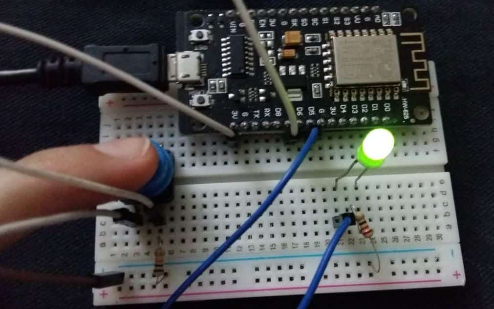
ESP8266 Digital Input and Output with Arduino IDE tutorial - Examples to use GPIO Pins of NodeMCU with LED and Push button
knotty tiger
what board name are you using in Arduino?
vast flume
 void sentinel
I would think in Arduino it would be called D2
vast flume
2 or D2?
void sentinel
I was looking at a guide on microcontrollers site and they mentioned 11 grio pins and not gpio2 on pin 17 and there was a comment on it that said hey you said 11 and there should be 12 and what about... And I thought... How ironic
2
I mean normally thats how they are referred to
void sentinel
Oh funny you gave that link. I actually was at the one for your board lol
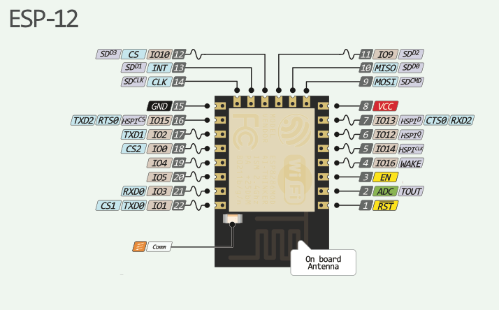
ESP12E WiFi Module Comlete guide starting with pin configuration diagram, Applications, how to interface with Arduno, Command modes
I was thinking that I was overthinking
that's why I started asking what may have been redundant
vast flume
All good
 vast flume
Oh wow 🤣
void sentinel
Then I got the ESP-CAM
Actually that should say ESP32-S2-TFT
I think I bought the rover from Adafruit as soon as I saw how cool it was in the Titano. even though that is a wroom.
And you are mostly really dealing with the samd51 in that. The esp is mostly just used for wifi
vast flume
Yeah
knotty tiger
static const uint8_t D4 = 2;
https://github.com/esp8266/Arduino/blob/master/variants/nodemcu/pins_arduino.h#L44
so it looks like GPIO2 is D4, if that's the BSP you're using? i'd have to look more carefully at the implementation to be sure
knotty tiger
yeah, usually digital pins are labeled on Arduino boards with simple integers that are inputs to the Arduino API. dunno why the NodeMCU pins are labeled as Dn and why the BSP uses the GPIO numbering for the Arduino API
also https://arduino-esp8266.readthedocs.io/en/3.0.2/reference.html#digital-io says the Arduino pin numbers directly correspond to GPIO numbers in that BSP, so you could probably just use 2 if you wanted
vast flume
@void sentinel @knotty tiger Thanks again for the help! 🙂
void sentinel
Ok I think I am done. Again. I also really find it hard to not just have this sent to the printer...

 hushed smelt
ha, i like all the acorns scattered around, that's cute.
woven bluff
I have the opposite problem. I have a hard time sending my design to fab because I can not be sure if I got everything right.
hushed smelt
oh i have plenty of shiny pcb paperweights from not getting designs right. got uart and spi lines mixed up once. that was disappointing. to be fair i designed that one when i didn't even know what spi was. i really need to remember to design them big enough to make drink coasters out of at least.
now i think of spi and i2c as magic busses ferrying data to and from components. it's whimsical and helps me remember never to make that mistake again. 😛
knotty tiger
have them shipped as panels? sure, you have to cut/separate them yourself, but it's easier to make coasters out the busted ones 😁
woven bluff
I dumped all flawed pcb recently. I don't need to be reminded of my failures every time I look at them.
void sentinel
Lessons, not mistakes.
If you are not failing, you are not innovating enough. Elon said that
Simone said she likes failing because it takes the pressure off...
My failed print drawer:

Not the same as the failed prints that go into the garbage.
Actually a lot of these weren't failures, just different iterations.
vast flume
Is this compatible with the adafruit jst connectors? https://www.digikey.com/en/products/detail/jst-sales-america-inc/S2B-PH-K-S-LF-SN/926626
Made the mistake of not asking last time and ended up with a connector that didn't fit
limpid nest
On some adafruit I2C boards, there are selectable pads to set the address. These pads make use of a pulldown resistor. If I have an I2C device and I just want it to have one fixed address, can I just pull its pads to GND/VCC as appropriate?
hollow flame
anybody haver a favorite MOSFET IC wiht maybe 4 internal fets that you can drive with 5v logic signals?
need to turn on four sets of LED strips, draw low enough power that usb power works, but can't pump that much out of arduino digital pins
did some searching on digikey but im not having a lot of luck
 twilit mango
limpid nest
On some adafruit I2C boards, there are selectable pads to set the address. These...
twilit mango
limpid nest
On some adafruit I2C boards, there are selectable pads to set the address. These...
Yes. You mean internally? As in physically on the board?
twilit mango
Yes, you can. Then don't break anything out to the user, and the address will be what you set it to on the board.
Typically on the Adafruit boards, even when you can change the address, the first address pin pad is always bridged to create the initial address.
limpid nest
oh sorry, to be super clear, I meant when making my own board
twilit mango
Do that, except not on a broken out pad.
I know what you meant.
I'm saying in your board design, if you want it to remain fixed, don't break the address pin out to the user. Then folks can't mess with it.
twilit mango
😄 You're welcome!
twilit mango
Because it ties the pin to GND or VCC, which changes the pin state. The device then sees that and alters the address it's broadcasting when scanned.
pale umbra
bit puzzled why this keep the adress static doesnt seem to be soldered to anything else
 knotty tiger
pale umbra
bit puzzled why this keep the adress static doesnt seem to be soldered to anythi...
knotty tiger
pale umbra
bit puzzled why this keep the adress static doesnt seem to be soldered to anythi...
i'd have to check a schematic to be sure. it's possible that the middle pad is the address selection pin, and one pad beside it is VCC, and the other GND
limpid nest
What's the point of pulling say an OE pin down rather than just tying it, when there's no other interaction with that pin?
knotty tiger
limpid nest
What's the point of pulling say an OE pin down rather than just tying it, when t...
can you elaborate on what the difference you mean between "pulling an OE pin down"? and "tying it"?
limpid nest
Using a resistor vs direct connection
knotty tiger
if you use a resistor, you can inject a high logic level later to override it. otherwise, if it's connected directly to ground, you'll have to break the connection to do so. also the resistor can be for safety reasons, sometimes
pale umbra
I feel like a I made a mistake getting a Pimironi PIM357- BME680 Breakout - Air Quality, Temperature, Pressure, Humidity Sensor
Like I was checking for a sensirion temp/humidity sensor and saw those Bosch 4-in-1
but since sensirio are 20$ and BME is 29$ I guess the accuracy is going to be really bad
limpid nest
knotty tiger
if you use a resistor, you can inject a high logic level later to override it. o...
That was my understanding but this particular circuit, the pin doesn't connect anywhere else
knotty tiger
limpid nest
That was my understanding but this particular circuit, the pin doesn't connect a...
to some extent, it might be a holdover from TTL logic families, because the inputs go directly to the base terminals of bipolar transistors, and can source/sink measurable current under static conditions. for those cases, it's good practice to use a resistor instead of directly wiring an input to GND or VCC. this can limit the idle current consumption, and also prevent damage to the rest of the circuit if there's a chip failure that ends up sourcing/sinking excess current from an input
also, even with CMOS, if the pin is an I/O pin, using a resistor can mitigate the damage if the pin is accidentally set to output mode to a conflicting voltage level
pale umbra
Do you guys mean the common technique of "Connect unused input pins to pull-up or pull-down resistors" ?
limpid nest
This is more properly biasing a pin
knotty tiger
pale umbra
Do you guys mean the common technique of "Connect unused input pins to pull-up o...
i think it's related, but i think this particular question was about if you want a pin to be at a fixed logic level in the board design
pale umbra
man 8 ma per pin on an atmel 32u, seems a very useless chip...
knotty tiger
pale umbra
man 8 ma per pin on an atmel 32u, seems a very useless chip...
which 32U? ATmega32U4? and which spec is the 8mA?
limpid nest
Usually you don't want to drive much of consequence from an MCU directly
Consequence meaning high current reqs specifically
Because you just can't
That 8mA per pin gets eaten up pretty quickly into the max current output of a chip like that.
pale umbra
yeah which is even worse since it's driving 4 motors and the whole thing goes at around 12-14mph
could be directly plugged to battery too, not sure don't really have a schematic
but the board uses an atmel 32U4
knotty tiger
pale umbra
but the board uses an atmel 32U4
where are you seeing the 8mA spec? because absolute max current for ATmega32U4 is 40mA DC per I/O pin
pale umbra
in polulu spec I think they put more pins out than the chip
like there is 3 pairs of i2c
rustic fulcrum
Pretty sure you'd only use the pins from a MCU to control something else which actually does the heavy power switching/current supply
knotty tiger
pale umbra
in polulu spec I think they put more pins out than the chip
in that case, please attribute specifications, limitations, etc. correctly to avoid confusing other people
 surreal summit
Hi all, I am hoping to confirm which pin is tip and which is ring in the breadboard friendly 3.5mm jack? https://www.adafruit.com/product/1699 pin 5 is Tip (LEFT) and pin 2 is ring (RIGHT)?

Pipe audio in or out of your project with this very handy breadboard-friendly audio jack. It's a stereo jack with disconnect-switches on Left and Right channels as well as a center ...
supple pollen
Yes, pin 5 is tip (left channel, the pin on the right in this view) and pin 2 is ring (right channel, the pin on the left in this view)
 surreal summit
@supple pollen Thanks for confirming it. The other jacks usually use pin 2 for tip so it almost confused me!
hushed smelt
most I2C addresses jumpers simply go straight to ground. the I2C chip itself does continuity/voltage checks on the I2C address pin, if it's grounded it sets the address internally. i actually just figured that one out a couple days ago doing the 16 step sequencer board with I2C expander bare chips.
the unsoldered pads for the I2C addresses are in a float state, when you solder bridge them they get grounded and the chip itself sees that and sets the address appropriately.
generally speaking, i'm not going to say it's like that for every I2C chip out there
unreal flax
hushed smelt
generally speaking, i'm not going to say it's like that for every I2C chip out t...
One interesting variant I've run across is for an address pin to want to be shorted to either power, ground, SDA, or SCL, so the chip can tell apart 4 address configurations with just one pin.
void sentinel
Also I want to start studying for my test. are there more preferable brands of solder paste?
hushed smelt
@unreal flax ohh that's interesting. will have to watch out for those. tricky buggers.
knotty tiger
hushed smelt
<@382380426628562955> ohh that's interesting. will have to watch out for those. ...
sometime the desire to reduce pin count leads to …interesting design decisions
distant raven
unreal flax
One interesting variant I've run across is for an address pin to want to be shor...
A particular TI i2c ADC has 8 possible addresses set by a combination of resistors in a resistor divider that feeds two pins. Talk about creative
 knotty tiger
distant raven
A particular TI i2c ADC has 8 possible addresses set by a combination of resisto...
knotty tiger
distant raven
A particular TI i2c ADC has 8 possible addresses set by a combination of resisto...
wow, i guess that makes sense. if you already have an ADC, why not add the address selection pins to the internal multiplexer and read analog values from those at startup?
distant raven
Yeah, pretty neat way to approach the “I need lots of these” problem
woven bluff
use 2 ADC just for addr sel?
knotty tiger
woven bluff
use 2 ADC just for addr sel?
seems wasteful until you consider the possibility that it's probably one ADC with an analog multiplexer
woven bluff
and 2-bit resolution?
knotty tiger
i assume it has more resolution, but they're only looking at the high bits for address selection
woven bluff
what about 256 addresses? something like FUSE?
knotty tiger
woven bluff
what about 256 addresses? something like FUSE?
what does FUSE mean here?
woven bluff
EPROM
knotty tiger
i'm still not sure what you're asking about
woven bluff
digitally programmable memory
with 8 bits to access all addresses
most chips only give you 2 or 3 options
I wonder how often do they collide
knotty tiger
if you mean I2C EEPROM devices, they're usually used to store configuration or calibration information, and there's usually no design reason to use more than one on a bus. and the I2C bus address space is only 7 bits (or 10, but that's rarely implemented), with some reserved
 inland jungle
mcp23018, cousin to the 23017 I2C I/O expander, also uses voltage division to set the address
distant raven
inland jungle
mcp23018, cousin to the 23017 I2C I/O expander, also uses voltage division to se...
Neat, I didn’t know that 🙂
supple pollen
void sentinel
Also I want to start studying for my test. are there more preferable brands of s...
Any of the good brands (Kester, Chip Qwik, etc.) are good. Note that there are different solder formulations, flux formulations, particle size, and solder density to consider.
inland jungle
distant raven
Neat, I didn’t know that 🙂
yeah, however I wish they were pin compatible considering their functionality is near identical
distant raven
Darn
distant raven
Weird.. it keeps saying there is a new message here but the there isn’t.. hmm
void sentinel
supple pollen
Any of the good brands (Kester, Chip Qwik, etc.) are good. Note that there are ...
I love variables. More ways to fail
 wicked root
distant raven
Weird.. it keeps saying there is a new message here but the there isn’t.. hmm
wicked root
distant raven
Weird.. it keeps saying there is a new message here but the there isn’t.. hmm
That was probably me - I thought for a bit and found the question more appropriate for general.
supple pollen
void sentinel
I love variables. More ways to fail
I like the small particle size pastes, they flow better.
 spice zenith
Is the following possible using a Feather board with an attached Li-Po? I'm thinking it could be prototyped on a Proto-Featherwing.
So I have a Feather that's normally powered by USB, what I want to do is detect loss of USB power and when that happens, gracefully shut down.
The Li-Po should easily keep the Feather going long enough for that, I'm expecting a graceful shutdown to take no more than a second or two: basically close and sync files that have been written to an attached sd card.
Then stay powered off as long as USB power is not available, but when it returns, power on the Feather again, and continue operation.
I'm thinking of an SR latch with the output attached to the "en" pin on the Feather. To turn off, pulse one side, so "en" is disabled and stays disabled. To turn on, pulse the other side directly from the USB bus power line.
IANAE, but I think that ought to work. Any thoughts? Does it have a chance, or am I completely out in left field here?
woven bluff
How do you properly solder QFP without stencil? last time I used solder paste and got shorting everywhere
I only have iron and heat gun
supple pollen
woven bluff
How do you properly solder QFP without stencil? last time I used solder paste an...
The short answer is use a very small amount of paste and lots of flux.
limpid nest
Does anyone know what kind of crystal adafruit uses on the RP2040 QT py?
pale umbra
limpid nest
Does anyone know what kind of crystal adafruit uses on the RP2040 QT py?
do you mean the specs or the particular brand/model ?
limpid nest
the particular model
distant raven
limpid nest
the particular model
I think they’ve used a few different ones, Dan has mentioned before, but I don’t recall the various ones mentioned
pale umbra
does it matter as long as you provide one for the specs just like resistors and caps ?
I don't know what to say/how to find that out because to me the brand doesn't seem like a factor
limpid nest
distant raven
I use this one with 27pF caps and a 953ohm series resistor
what does the series resistor do?
distant raven
Reduce drive strength, lengthening the life of the crystal
The RP2040 HW design guide heavily suggests adding a 1K with the 50ohms ESR crystal they picked. The one I use is 100ohm ESR so I adjusted the drive resistor down by ~50ohms
pale umbra
If it help someone to answer the question this is the crystal in the schematic
 knotty tiger
pale umbra
If it help someone to answer the question this is the crystal in the schematic
knotty tiger
pale umbra
If it help someone to answer the question this is the crystal in the schematic
the crystal is probably the two-terminal device labeled nevermind; misreadY1
knotty tiger
limpid nest
Does anyone know what kind of crystal adafruit uses on the RP2040 QT py?
why do you ask?
pale umbra
I wonder that too, just need any 22pf/12mhz crystal
but not in the sense that I am questioning the reason, more like I'm surprised and would like to know if it matters because I assumed its like caps and resistors
knotty tiger
the RP2040 datasheet should have detailed requirements for the crystal and supporting parts to achieve the recommended operating conditions. if you need better performance than that, it would be good to know more about what you're trying to do @limpid nest
limpid nest
I was specifically looking to know about the crystal that adafruit uses, it's not urgent though
distant raven
From my understanding Adafruit has used a few different 12MHz crystals on the feather rp2040 so it just depends on what they are using now
knotty tiger
limpid nest
I was specifically looking to know about the crystal that adafruit uses, it's no...
is this still about trying to achieve millisecond timing accuracy over 7 hours?
limpid nest
only tangentially, I'm mostly interested in how the crystal will affect that goal
knotty tiger
one millisecond per 7 hours is in the neighborhood of 20 parts per billion. edit: oops was off by order of 1000, so it's actually close. i'm reading that 32kHz watch crystals are usually in the range of 20 parts per million if not temperature-compensated. multi-MHz crystals like used with MCUs seem to be in the 100s of ppm, though
pale umbra
I'd just email support@adafruit.com at this point and ask them if I were you OatsNHoney
limpid nest
knotty tiger
~~one millisecond per 7 hours is in the neighborhood of 20 parts per _billion_.~...
Oh sorry, I clarified elsewhere, I explained badly. I only need ms accuracy over 3-5 minutes but I need to repeat that many times over 7-8 hours
Which I'm pretty sure the qt can handle with ease
pale umbra
otherwise you are just betting on a low-probabiliy of kattni/etc seeing the question
limpid nest
But now I'm just curious what the error bars are
knotty tiger
the main contributor to rate error in crystal oscillators seems to be temperature, and maybe to a lesser degree, aging. temperature compensation, or oven control, are ways to get orders of magnitude improvement for frequency stability. neither is commonplace on MCU boards (though you can kind of hack temperature compensation if there's an onboard thermometer)
pale umbra
I keep seeing this topic and it seem easier to make a 60 khz receiver and synchronize a timer with no drift on it than to even find the right crystal to start a timer with no drift project 😦
limpid nest
it's not necessarily easier if you're working in a language without interrupts
knotty tiger
precision timekeeping is hard. that's why the people who do it get the big bucks
pale umbra
yeah but receiving 60 khz is much easier no ?
and reading the bits that keep being broadcaster over and over ?
limpid nest
I'm prototpying so I can always try that if it doesn't work
pale umbra
an atomic clock probably don't drift much ?
knotty tiger
you don't even need to read the bits, if you don't care about the exact time. just phase-lock to the carrier
pale umbra
I'm kinda disappointed in atomic clock projects when they just receive 60khz and not measure an atom themselves 😦
knotty tiger
pale umbra
an atomic clock probably don't drift much ?
the specified atomic oscillation of the cesium atom is the definition of the second. granted, it's been refined to specify in free fall, at absolute zero, so practical atomic clocks have to apply corrections for operating on a gravitating body at a temperature above 0K
limpid nest
What's the utility of a series resistor and a pull down here? I've always just seen RX/TX connected directly
 inland jungle
that's likely a voltage divider to convert 5V TX to 3.3V RX
limpid nest
ah that makes sense
pale umbra
that's what I thought too but why not on TX ?
and both chips seems to be 5V
my only hypothesis is that since the RX pin is used as output instead of as input normally you have to protect it
spice zenith
A little late to the party, but @limpid nest do you have network connectivity on the RP 2040 you're using? If so, have you considered pinging the public NTP servers, like pool.ntp.org. Your worst error there will be approx half of the round trip time, which for most people means either single digits or low double digits of milliseconds.
I've built a couple of clocks here, one used an ESP8266, so it's very possible using Arduino, and I'm working on a project now in CircuitPython that's successfuly doing the same thing.
That does depend on what's an acceptable error for your project, of course.
limpid nest
spice zenith
A little late to the party, but <@887510739462537236> do you have network conne...
Nice thought! I won't have connectivity though unfortunately
inland jungle
pale umbra
and both chips seems to be 5V
There's no reason to lower the voltage of 3.3V going into 5V compatible pins
Also, the MCU on the right is almost certainly 3.3V
unreal flax
woven bluff
my 5V1 zener is burning hot
Sounds like it's multimeter time.
woven bluff
unreal flax
Sounds like it's multimeter time.
didn't bother, now I know why most IC rated 5V5
 bitter flare
Hacking this Open hardware bot around https://github.com/rosmo-robot/micro-bot/blob/master/Hardware/V2.11/readme.md can anyone help review before I make a few?


GitHub
Hardware & Firmware for BBC Micro:bit sumo bot. Contribute to rosmo-robot/micro-bot development by creating an account on GitHub.
 signal topaz
bitter flare
Hacking this Open hardware bot around https://github.com/rosmo-robot/micro-bot/b...
signal topaz
bitter flare
Hacking this Open hardware bot around https://github.com/rosmo-robot/micro-bot/b...
i am not super familiar with github, but is it possible to download whole "V2.11" catalog as single zip archive?
- I think you are missing decoupling capacitors
- switch (?) in lower left has no unmasking on pads
bitter flare
signal topaz
i am not super familiar with github, but is it possible to download whole "V2.11...
GitHub
Hardware & Firmware for BBC Micro:bit sumo bot. Contribute to rosmo-robot/micro-bot development by creating an account on GitHub.
bitter flare
signal topaz
1. I think you are missing decoupling capacitors
2. switch (?) in lower left has...
Could you say more about the caps? Where should they be do you think?
signal topaz
At each IC. Use ceramic capacitor at your smallest used size, I think you are using 0402. Something like 100n or 1uF
close to supply pin, and add local via to GND plane, near capacitor pad
bitter flare
Good catch on the switch 🙂
signal topaz
also for U1, use some thicker connections for the GND pins in center of the package. I think it should act a little bit as a heat sink
in datasheet they also suggest adding some GND pour on top layer, going north and south of the package for heat dissipation
but capacitors is a must to have. On 6V you have completely no capacitors. You might want to add something bigger there as well
bitter flare
@signal topaz Nice thanks 🙂
wicked root
If the board that you're using is or is like the M0 Adalogger, it sounds like you might be on the right track:
https://learn.adafruit.com/adafruit-feather-m0-adalogger/power-management
You would likely need to add something like a P-channel MOSFET to act like a normally-closed switch, so that you don't need to drain your battery to connect En to Gnd.
I'm not an expert but maybe something like this:

 supple pollen
I think you'd want an N-channel MOSFET there, or just drive the enable input directly from the Q output.
wicked root
You're right I reversed S and R while I was diagramming.
wicked root
supple pollen
I think you'd want an N-channel MOSFET there, or just drive the enable input dir...
Wait...if the desired behavior was for the V USB pin to "open" the FET between En and Gnd, and the Out pin to be able to "close" FET, wouldn't this be correct?
Effectively wanting the "switch" to be !Q, so that minimal energy is required to power down.
 warm bluff
Hey guys
I have a flex sensor
Now I just needed to know what resistor I need yo use for the flex divider
Do I use 220 ohms? 20 ohms?
Wdid
unreal flax
warm bluff
Now I just needed to know what resistor I need yo use for the flex divider
Generally you'd want to use a resistor which is approximately the same as the resistance of the sensor itself, to maximize the effective range of the readings. So you'd want to check the sensor datasheet, or measure it with a multimeter.
warm bluff
unreal flax
Generally you'd want to use a resistor which is approximately the same as the re...
is there any way you can find the resistance of the sensor without using a multimeter

Thin Film Pressure Sensor Flex/Bend Sensor ZD10-100 500g Resistance Type FSR Sensor Thin Film Pressure Sensor Force Sensing Resistor, Force Sensitive Resistor
this is the flex sensor and im not able to find the amount of resistance needed
unreal flax
warm bluff
this is the flex sensor and im not able to find the amount of resistance needed
The fourth picture in the listing seems to imply that 10kOhm would be a good choice of resistor for it.
unreal flax
Possibly, yes. It might have broken the electrical path.
knotty tiger
even if it doesn't break the electrical path completely, it might change the characteristics enough to make it less accurate or repeatable
 umbral sphinx
Does the Monochrome 0.91" 128x32 I2C OLED (product ID: 4440) need pull-up resistors on the I2C lines if my microcontroller doesn't have them on-board?
Looking to drive it with a Pico
supple pollen
No, it includes both pull-up resistors and a level shifter, so you don't need additional ones.
umbral sphinx
noice. that'll be perfect, then
Does Adafruit sell a pack of screws and nuts that will fit the holes on that display board as well, or should I source those elsewhere?
 dry pelican
This is my Tesla Coil Power driver board that I'm designing. Will the copper fills on the power side (right side) cause any problems with the MOSFETS being driven? (ringing, too much capacitance, capacitive coupling, unwanted inductance). The PGND (power ground) is the fill on the bottom (connected to the source of the bottom MOSFET). The PVCC (Power V+) is connected to the drain of the top MOSFET through the top copper fill. The Primary connection is connected to both MOSFETS through a bottom plane. It's a half bridge arrangement.


It's a half bridge, but you can combine 2 and reverse the phase on one for full bridge operation
The coils that I have built resonate at around 1.2MHz
PCB details: 1.6mm, all 2mm traces on right side, 0.254mm clearance
supple pollen
I suspect the MOSFET gate capacitance will be more than the capacitance caused by the ground fills, so I don't anticipate any problems from that. Inductance shouldn't be an issue, as ground fills are low inductance.
dry pelican
That's what I would think, but my last design had an issue where I just couldn't get it to oscillate, which I suspect was caused by having a ground plane after the mosfet driver, and not using it according to how it was recommended in the datasheet. It was a single mosfet coil driver, though.

This is the old one
Although it did oscillate a few times, but it won't anymore
It might be because I haven't tried something like getting some fresh driver ICs or feeding the circuit higher current (but the circuit does have tendency to get stuck (as the small capacitance of the input of the hex inverter IC holds some charge and turns the rest of the circuit on), meaning that I'm afraid to bump up the current limit to 8A because I may fry the MOSFET, the board, or both)
supple pollen
The first thing I try on boards like that when they won't oscillate is swap the leads on the driver transformer
You even seem to have a phase jumper for that very purpose
dry pelican
The old board (V1) had no drive transformer
Maybe that had something to do with it
I also did not have much protection on the driver
except for a 1.5ke12CA
supple pollen
The single MOSFET ones sometimes need something to kick them into operation, as they can sometimes find a stable steady state where they're sort of half-on
My single MOSFET boards all use a separate oscillator, which will reliably oscillate but won't self-tune
dry pelican
What I would do is touch the antenna, which would cause the 60hz line noise to turn the hex inverter on and off and cause it to start oscillating
A breadboarded version actually worked very well with a very similar circuit
supple pollen
Yeah, that's the "something to kick it into operation"
dry pelican
So that's part of the reason why I suspect it's the ground plane
supple pollen
I rather doubt it's the ground plane
I only left a ground plane off my little flyback driver because I have the HV on the board and wanted to avoid corona
 dry pelican
it is 1.2MHz though, so there's a possibility that the ground plane acts as a low pass filter. But I think that's unlikely since higher frequency things have ground planes
supple pollen
Right. The ground plane will add a few dozen picofarads of capacitance, but the MOSFET gate is going to be much more, so it's not likely to have much of an effect.
dry pelican
The UCC37322 datasheet says "If a ground
plane is used, it may be connected to AGND; do not extend the plane beneath the output side of the package
(pins 5 – 8). Connect the load to both OUT pins (pins 7 and 6) with a single trace on the adjacent layer to the
component layer; route the return current path for the output on the component side, directly over the output
path."
I did not read the datasheet until later, and just connected AGND and PGND together
and used a ground plane
supple pollen
Assuming 10Ω of resistance (since that's what you have on the board) and 50pF of capacitance, it would be about 10dB down at 100MHz. That "low pass filter" isn't going to affect much of anything at 1.2MHz.
dry pelican
there's also 2000pF on the MOSFET gate
supple pollen
Right: that's going to determine the cutoff frequency, not your ground plane
dry pelican
7.76
MHz
cutoff
so that shouldn't affect much of anything (it might even be beneficial because it could filter any high freq harmonics)
supple pollen
Note that "cutoff" doesn't mean "no signal gets through above this", just "3dB down at this point, and you'll be getting phase shift"
dry pelican
yes
But why does the datasheet say to have no ground plane near the output
The UCC47425 has nothing telling you to not use a ground plane
supple pollen
I can't find that verbiage, but it does say "Use a ground plane to provide noise shielding."
It does say "The ground plane must not be a conduction path for any current loop." which is slightly odd but possibly intended to keep ground bounce out of the ground plane.
It does say "The gate driver should be placed as close as possible to the MOSFETs." which you're not really doing in your design, and offers this layout example, showing the (short) drive and return paths overlaid so they enclose the minimum area.

That gate drive transformer looks pretty chonky, I'm used to a little toroid with flying leads
woven bluff
dry pelican
This is my Tesla Coil Power driver board that I'm designing. Will the copper fil...
Why not use a two channel gate driver instead of GDT?
also you can filter out DC by adding large series cap at terminal 1 and 3 of the transformer
signal topaz
dry pelican
PCB details: 1.6mm, all 2mm traces on right side, 0.254mm clearance
what is PVCC voltage? in relation to PGND
dry pelican
woven bluff
Why not use a two channel gate driver instead of GDT?
The GDT provides galvanic isolation sot that the higher voltage power side is isolated from the lower voltage driver side. It also provides the right driving voltage to the top mosfet of the bridge (instead of bootstrapping).
dry pelican
signal topaz
what is PVCC voltage? in relation to PGND
It'll be very variable. Lowest will probably be 12v, but I might want to run it lower just to see how low it can go. Highest will likely be 30v, or maybe even 60, but I'm never going to run it off 120V AC because I don't want to have to deal with death capacitors.
dry pelican
supple pollen
That gate drive transformer looks pretty chonky, I'm used to a little toroid wit...
It'll likely be smaller, but that was the footprint that I found (although I could just make my own).
supple pollen
I wonder if you could get what you need an an EP5 package https://www.coilcraft.com/en-us/products/transformers/power-transformers/gate-drive/da23xx/
dry pelican
That could work. That transformer is pretty inexpensive and would have more predictable characteristics (which would work better when I go full bridge) than a hand-wound one. It's also smaller, so that might reduce unwanted inductance. I would still stick with tht for the resistors, capacitors, and phase jumper. A tht hand-wound gdt would be more customizable, swappable, and testable, though. I might make another revision of the power board with lower inductance and smaller loop area in mind. (Probably with my own gdt footprint). I assume that the current design is "pretty good", but could be made better. Another thing I could do to minimize inductance after I find the resonant frequency of the coil is to use a capacitor that resonates with the inductance of the transformer and the traces to drop that impedance to almost 0 (like a drsstc). (Although I would need a very precise and accurate inductance meter.)
hushed smelt
signal topaz
what is PVCC voltage? in relation to PGND
Pvcc is likely the constant current to the associated ground. You’ll see avcc and agnd sometimes too. Technically it stands for analog gnd but naming is less important than its intended function. Just means it wants a different gnd plane than the normal net gnd… from what I understand, I could be wrong, do some research on it.
signal topaz
dry pelican
It'll be very variable. Lowest will probably be 12v, but I might want to run it ...
I would suggest to increase copper clearance between all nets: PVCC, switch node, and PGND.
It might be also good idea to have some placeholders for snubbers for MOSFETs.
dry pelican
signal topaz
I would suggest to increase copper clearance between all nets: PVCC, switch node...
To reduce capacitance and the chance of arcing?
signal topaz
So I am not an expert in those high-voltage systems, but I do not think we can expect some high voltage (>1kV) between those nets on that PCB, correct?
I would increase the clearance just to avoid some problems with dirt, debris, humidity, flux residues, or something like that. I would just expect bigger clearances in systems >48VDC.
 worn sinew
I'm trying to create a UPS of sorts with my keyboard and a Feather 32u4 BLE, but I'm not sure what I need to make this work (I'm new to this). I made this diagram to show what I mean. Ideally, the usb pin should power the keyboard when the usb is connected to the feather

I was thinking the blue line would be a transistor, but that wouldn't really work because to my understanding, this diagram looks more like an 'OR' gate than a transistor
supple pollen
The easiest way is with steering diodes, which lets the highest voltage flow through. Another approach uses a diode for the 5V line and a MOSFET for the battery line, to avoid the voltage drop of a diode on the lower voltage line.
woven bluff
@supple pollen how's your divergence meter going?
supple pollen
Version 2 is kinda stalled, I should pick that up again
 dry pelican
signal topaz
So I am not an expert in those high-voltage systems, but I do not think we can e...
dry pelican
signal topaz
So I am not an expert in those high-voltage systems, but I do not think we can e...
Neither am I an expert in HV stuff. There shouldn't be any 1kV+ spikes because I will add TVS diodes and/or BEMF diodes. (If there are any, it would be in the moment before the MOSFETs die). I do agree with increasing the clearance. It won't hurt (and it will probably more desirable because it decreases capacitance). I'll have to add all that in version 3 of the power board. (Version 3 because the one I posted is actually Version 2)
dry pelican
worn sinew
I'm trying to create a UPS of sorts with my keyboard and a Feather 32u4 BLE, but...
I agree with @supple pollen. 2 diodes that have connecting cathodes is the simplest way (make them schottkeys for low voltage drop). You can also use a mosfet and a diode. If you need ideas, look at some adafruit or sparkfun board schematics that have a USB and LiPo input. If you really want to go maximum efficiency but maximum complexity, you could use 2 ideal diode circuits.
dry pelican

 glacial gale
dumb question: are cpu registers usually shift registers? like parallel in parallel out?
unreal flax
glacial gale
dumb question: are cpu registers usually shift registers? like parallel in paral...
That's not really the definition of a shift register, but they're usually accessed as a 32-bit-wide piece of memory, similar to how SRAM is read and written.
glacial gale
unreal flax
That's not really the definition of a shift register, but they're usually access...
hm right, but a load instruction would be much store entire word in one go right?
unreal flax
glacial gale
hm right, but a load instruction would be much store entire word in one go right...
Yes, that's correct.
knotty tiger
yeah, CPU registers are usually parallel load/store for speed. some CPUs have barrel shifters in their ALUs (or similar components) that allow single-clock shift or roll of arbitrary amounts, but they're usually not part of the register file design
woven bluff
I don't know why but somehow the blanking pin of a shift register has internal 100Ohm connected to VCC.
I checked 3 chips, and got 20MOhm, 400Ohm, 100Ohm
all chips are working, but I don't have enough logic current to drive the 100Ohm chip
knotty tiger
how are you testing them? if you're using a multimeter, have you tested with the probes reversed as well? resistance readings on chips can be misleading because of diodes and other semiconductors
knotty tiger
woven bluff
all chips are working, but I don't have enough logic current to drive the 100Ohm...
that seems unlikely. datasheet says I_IL is -1uA max. try grounding the blanking input through a 1kOhm resistor. you shouldn't read anything more than 1mV on it from the input bias current while powered on; otherwise, you might have a defective part
woven bluff
that's too many defective parts, I added 1KOhm pull down, the blanking line has 1 V when driven down
knotty tiger
woven bluff
that's too many defective parts, I added 1KOhm pull down, the blanking line has ...
yeah, that seems outside of spec. how are you wiring these up?
woven bluff
3 in series
knotty tiger
breadboard? custom PCB?
woven bluff
all share blanking, SCK, Latch
 knotty tiger
was the 1V from pulling down all 3 blanking lines together? or did you test that chip individually?
(still out of spec though)
woven bluff
yes, 1V with three
only one chip is in spec
the other two draw way too much from the blanking
I have 6 chips, 1x20MOhm(in spec), 2x 400Ohm, 3x100Ohm
my driving capacity is only 20mA
knotty tiger
again, how did you measure the resistance?
woven bluff
multimeter, both direction has the same resistance
knotty tiger
when not installed?
woven bluff
yes, when installed the total resistance is the harmonic mean of each one
those dam_n chip costs £8 a piece
knotty tiger
it's orders of magnitude out of spec. i'd suggest taking it up with the supplier. is it a reputable supplier?
woven bluff
digi-key, came in cut-tape
knotty tiger
and when you tested the pull-down on the blanking input, were all other inputs at defined voltages?
woven bluff
yes, all other digital pin has >1MOhm resistance, and all behaves at 5V
knotty tiger
otherwise, it's possible that your board has a wiring error, or stray conductive paths from solder. (unless you've tested each chip in isolation?)
woven bluff
the board is fine, tested
maybe a bad batch, I'll order 3 more from Mouser
otherwise, this is the ideal chip to drive Divergence meter
the strange part is that those chips even work at this defected condition
knotty tiger
they work apart from the excessive input current on the blanking input?
woven bluff
yes
knotty tiger
that does make me wonder if it's an assembly issue
woven bluff
I drag-soldered them, PQFP
knotty tiger
VDD is adjacent to /LE on the QFP pinout, so i'm a bit suspicious because of that
maybe try reflowing and a thorough defluxing?
woven bluff
the fact that individual chips have different resistance is suspicious
after I noticed the problem(not blanking) I hot air them off to examine individually
knotty tiger
oh, you actually probed them individually when uninstalled? could still have conductive residues
woven bluff
when using MOSFET as diode, is it better to use N channel or P channel?
dry pelican
woven bluff
when using MOSFET as diode, is it better to use N channel or P channel?
I don't think it matters. I've seen power switching and reverse polarity protection circuits that use mosfets as diodes (power switching (power preference) circuits use n-channels, and reverse polarity protection circuits use p-channels). N-channel is more common and has lower on resistance, but I don't think it affects the diode. But why do you want to use a mosfet as a diode?
dry pelican
woven bluff
I dont want forward drop
Where is this diode in the circuit?
supple pollen
woven bluff
when using MOSFET as diode, is it better to use N channel or P channel?
The approach I usually see (this is the schematic for the AdaFruit M4 Feather power supply) is to use a P-channel MOSFET to replace a diode
 distant raven
supple pollen
The approach I usually see (this is the schematic for the AdaFruit M4 Feather po...
distant raven
supple pollen
The approach I usually see (this is the schematic for the AdaFruit M4 Feather po...
And oh does it work very well. I’m a big fan of this approach
woven bluff
Now all of my HV5530 chips are dead
I'll transplant the components to a new board when I go to lab tomorrow
I also ordered some new HV5530
@supple pollen What's your solution for your divergence meter?
supple pollen
You may not like the old inefficient 74141 chips, but I'll say this for them: they're robust.
woven bluff
this time I'll test the new chip off the reel for resistance
I gave away my old divergence meter, which is 3xHV5530 driven directly by Arduino nano
supple pollen
Another approach is David Forbes' nixie watch, which uses TD68023 chips as cathode drivers (along with an interesting 60V "pull mid" clamping arrangement to avoid overloading them with too-high voltage)
woven bluff
the new version is isolated, 3xHV5530 driven by MAX14930
supple pollen
I think the ArduNIX board uses discrete transistors, similar to the old four letter word kit.
woven bluff
I know the Darlington transistor approach, but the HV series chip just too nice and convenient
supple pollen
Nope, I'm wrong, the ArduNIX uses the same 74141 chips as my divergence meter
woven bluff
if you want your divergence meter compact as the one in Anime, you'd better off with HV series chip
supple pollen
Yeah, the combination of shift register and high voltage driver and a bunch of channels in a single chip is attractive (aside from the 12V signalling a bunch of those chips use)
woven bluff
supple pollen
Yeah, the combination of shift register and high voltage driver and a bunch of c...
tested 3V3 and 5V works
supple pollen
The one in the manga and anime was fairly bulky, plenty of room for DIP packaged chips
woven bluff
you forgot the battery
supple pollen
The battery is going to be similar for most designs
woven bluff
I put an Adafruit ChargeBoost 1000C on my design
supple pollen
My version 1 was pretty chonky as I threw it together out of parts I had lying around in a few days for cosplay. Version 2 is intended to be somewhat more compact.
woven bluff
 supple pollen
I ended up using a chonky 3S1P lithium pack because I have a bunch of them available for drones, props, R/C cars, ham radio gear, etc.
woven bluff
input power typeC->load switch->ChargeBoost 1000C+UVLO supervisor
I want to order a custom li-po from aliexpress
 woven bluff

My old V2, gave to my friend today.
this one is 3xHV5530 driven by Arduino Nano 33 IoT
supple pollen
The original breadboard version
 woven bluff
is that IN-8-2?
 woven bluff
what value is your drop resistor?
supple pollen
I think it's 15kΩ, but that's from memory and could be wrong
woven bluff
I use 47K and additional 470k on the dots
supple pollen
Amusingly, the CPU in that last pic is a genuine AdaFruit Boarduino. I built those into all sorts of projects.
knotty tiger
supple pollen
Amusingly, the CPU in that last pic is a genuine AdaFruit Boarduino. I built th...
wow i might still have one of those around
woven bluff
at some point I shoved all AVR boards to a dark corner of the lab and never be found
supple pollen
I finally started buying the blank boards and getting the components separately
 knotty tiger
i still have a soft spot for the 328P and 32U4
also i have a small tube of 328P chips that i never got around to building into stuff
woven bluff
now I have no working clock I cannot even sleep.... time for pills
hopefully Mouser will deliver the parts before I explode
void sentinel
 void sentinel
How would I find out the resistance of the ferrite beads from https://www.adafruit.com/product/4101 ?

Thermocouples are very sensitive, requiring a good amplifier with a cold-compensation reference. The Adafruit MCP9600 does all that for you, and can be easily interfaced with any ...
I don't know much about ferrite but when I went to order some, apparently that is a variable. lol
 pale harness
Hey there!
Here i lock the power going to the dashboard of an escooter. When you press the button, you only turn on the microcontroller which then waits for custom unlock requirements and then let's it through to the dashboard. If not unlocked for X minutes i want to simulate a long button press, in order to turn the scooter and the MC off. However i am quite unsure how to do that here. Any help would be appreciated ❤️
Can i do another P channel setup, connecting Drain to Ground with a resistor in between & Green to Source?
Greetings from Vienna
 pale harness
would that work?
 supple pollen
pale harness
would that work?
supple pollen
pale harness
would that work?
I suspect that would work, but it's probably overkill. The transistors depicted are TO-220 power types, I don't know if the actual ones are, but you probably don't need something that powerful just to emulate a microswitch. I'm also unsure why a pair of transistors is used instead of just one. It could be acting as an inverter, but that seems easier to do in software. It could be acting as a driver, which would probably only be necessary when switching a large amount of power.
pale harness
supple pollen
I suspect that would work, but it's probably overkill. The transistors depicted...
hey. I just used parts i've laying around. And using the N+P combination because i've to switch the high side and the N channel so it does not go ON when the microcontroller is still booting.
limpid nest
what would folks call an H Bridge driver that has gate driver outputs instead of built in FETs?
inland jungle
aren't most of them like that?
limpid nest
most of them have internal fets, to my knowledge
I'm looking to drive a motor with a high stall current
knotty tiger
i think they're simply called "H-bridge gate drivers"
limpid nest
ok I'll google that, thanks
knotty tiger
https://www.nxp.com/products/power-management/smart-switches-and-drivers/pre-drivers/h-bridge-gate-driver-ic:MC33883
is one i found with a quick search
The NXP MC33883 is an H-bridge gate driver IC with integrated charge pump and independent high and low side gate driver channels.
limpid nest
I'm making a library part for this device (an RP2040 stamp) in KiCad. How would folks label pins 1-30? I was thinking just GPIO0-29 but I'm not certain
 supple pollen
pale harness
hey. I just used parts i've laying around. And using the N+P combination because...
supple pollen
pale harness
hey. I just used parts i've laying around. And using the N+P combination because...
There's a pull-down resistor to set the state when the microcontroller isn't driving it, and you don't need a high side switch to parallel the microswitch (which acts as a low side switch, grounding the signal it's connected to when actuated)
distant raven
limpid nest
I'm making a library part for this device (an RP2040 stamp) in KiCad. How would ...
Arturo has a footprint for it for KiCAD already 🤔
supple pollen
limpid nest
hard to find any in stock
If I do a search for "gate drivers" on Digikey, select parts in stock, and exclude marketplace items, there are still over 1000 different options, including common ones like ICL7667, MAX4427, and TC4427
distant raven

GitHub
Contribute to solderparty/rp2040_stamp_footprints development by creating an account on GitHub.
pale harness
supple pollen
There's a pull-down resistor to set the state when the microcontroller isn't dri...
makes sense, i got confused a lot. Many thanks ❤️
limpid nest
distant raven
Arturo has a footprint for it for KiCAD already 🤔
I don't think this is his stamp
Oh maybe it is
 limpid nest
Yeah just noticed that
distant raven
Arturo makes some really cool stuff, hopefully those footprints help 🙂
Or saves some time anyway
 rustic linden
limpid nest
I'm making a library part for this device (an RP2040 stamp) in KiCad. How would ...
rustic linden
limpid nest
I'm making a library part for this device (an RP2040 stamp) in KiCad. How would ...
I'd go with D0-29, and A0-3
dry pelican
limpid nest
what would folks call an H Bridge driver that has gate driver outputs instead of...
maybe an h-bridge pre-driver
dry pelican
I'm hoping this is a really easy question: I'm trying to make PartSim work, but it refuses to make any sort of graph. When I press run, and all it does is generate a "report". How do I simulate something in PartSim version 2.2.7?

 distant raven
I have some comparators I bought for a VLC project I left and part of me wants to make a coax sniffer
Take a coax connector, feed it into the comparator and then fill a 16 bit buffer on an fpga and push that out to a bank of LEDs
Just to get a crude visualization of the data
supple pollen
That would be fun to watch, especially if it could do things like pick up details of baseband video, QAM, etc.
distant raven
Yeah, I’d need to learn qam demodulation, but definitely a cool idea
dry pelican
distant raven
Take a coax connector, feed it into the comparator and then fill a 16 bit buffer...
would you need the FPGA though? Maybe you could do it with a shift register and some clever circuitry, but maybe I'm wrong.
distant raven
FPGA for speed
dry pelican
FPGAs are fast but they can be expensive
distant raven
I’ve got that covered
 dry pelican
and using one just to fill a buffer seems like underutilization (although I'm also the type of person that puts unnecessarily powerful hardware in stuff that really doesn't need it)
distant raven
The FPGA wouldn’t need to be crazy complex. Mostly looking for fast acquisition and output. Plus some internal logic
dry pelican
yes I guess you would need that to figure out a clock signal from just a pulse train
to put in a shift register
distant raven
TTL logic would be too slow to sniff coax lines in my house
Propagation delay and whatnot between chips
dry pelican
it doesn't have to be a ttl shift register
yes and capacitance and inductance and whatnot
if you were to build it out of discrete logic chips
but maybe you could use the propagation delay?
distant raven
A shift register implemented on an fpga would be fast since I’d have to shift 16 bits at a time, load them to an output buffer that would shoot it out
I’d have to derive timing like you said which would be interesting
woven bluff
the only thing I don't like about FPGA is that there's no opensource IDE
I remember some project trying to crack bit streams but in the end not production-ready.
unreal flax
I haven't used them myself, but I think the Lattice open-source tools are at least mature enough to use in real projects.
woven bluff
FPGA development bring back nightmares like Keil
supple pollen
woven bluff
the only thing I don't like about FPGA is that there's no opensource IDE
Yes there is, check out IceStudio / IceStorm. That's what I use.
I tried for years to get the vendor tools to work but never managed.
distant raven
I’ve used IceCube2 on windows pretty painlessly
 oblique flint
Anyone here happen to have a glowforge? I'm curious to see how the black hinges are installed on it
supple pollen
The last time I used windoze was before FPGAs or even CPLDs were a thing, back in the 1900s when 22V10 was a nice device and PALASM.EXE was the way to build the fuse map (although you could do it manually, the data sheet showed the entire fuse map for the device).
Or WINCUPL.EXE. However for me, "painlessly" and "windoze" do not go together.
woven bluff
sadly I need windows for DirectX
supple pollen
Well I'll be, you can still buy 5V CPLDs these days...
woven bluff
is it possible to remove a TCXO RTC chip from a breakout board without damaging it?
cannot find any TCXO RTC chip in stock, but I have some DS3231 and DS3234 breakouts
distant raven
woven bluff
is it possible to remove a TCXO RTC chip from a breakout board without damaging ...
Sure! A little flux, solder wick, and a good iron/hot air gun
woven bluff
I'm concerned that hot air gun would damage it
distant raven
Most chips can handle 2-3 times of being reflowed without damage
woven bluff
and why would you need solder wick if you have hot air gun?
distant raven
Solder wick for if you don’t have a hot air gun
woven bluff
I have removed SOIC with solder wick and razor blade before, pin by pin
for hot air, I usually use 500C 20%
distant raven
500C 😶
woven bluff
too hot?
distant raven
I’m not a thermodynamics experts
But I believe my station is in F in which I use 500F for hot air
woven bluff
I also bought lowest melting point chipquick paste
distant raven
Though I try lower temps when I can, 450F.
That stuff will wet at 150C so great to work with if you do a lot of rework
I use it as well
 distant raven
Hmm
dry pelican
woven bluff
cannot find any TCXO RTC chip in stock, but I have some DS3231 and DS3234 breako...
Ah yes, the chip shortage strikes again.
woven bluff
OK, the blanking pin resistance of HV5530 is 600K for the 4 pieces I bought from Mouser
humm, one became 12M after soldering
 gusty aspen
Hi folks - I'm having a real brain fart moment. Hoping someone can help me untangle this from my brain.
I have the 2.13" tri-color e-ink display I am hooking up to a Node MCU ESP 8266 board. Here's my Fritzing. Everything is working great, and I'm ready to move it into a permanent case to mount on the wall. My plan was to solder in some female headers to a perma-proto board, put the Node MCU board in there, then I got some 7-wire JST cables to use to connect the E-ink display, since I'm only using 7 of the pins.
What's tripping me up is that the female end of the JST is just the pins, and the male end has the wires. I can't put the female end on the perma-proto, because they're in the wrong order. I wanted to make sure that if either the board or the e-ink display has to be replaced, I can remove just that component, so that's why I'm using the JST connector (especially given the cost of the e-ink display!) On another project I soldered one of my Node MCU boards directly to the perma-proto to save on space, then a few weeks later had to change something and it was a huge pain 🙂
What am I missing? How would you build this as a finished project?

These are the JST cables I got

 fervent lance
Why not cut and strip the conductors of a double-ended cable so that there are wires on both male and female connector ends?
gusty aspen
Hmm, I'm following... I actually couldn't find any pre-wired 7-pin JSTs that had connectors on both ends, or both sides with wires, all I could find was this kind of set. Do you mean like the connected dupont type cables?
It doesn't have to be JST I just wanted to make sure nothing would come lose when we mount it on the wall or anything, so I figured a good connector would be smart.
That was supposed to be I'm not following. Wow having trouble typing today
fervent lance
I'm guessing 'miniaturization' is a design goal - wires that stick out axially from the pins they are connecting (at a moulded plug housing) tend to eat more stacking space than two or three flat boards they are meant to interconnect. ;)
gusty aspen
I would like to keep it fairly thin because it is going on the wall. There's a 9V battery going in so that's about as "thick" as I want it. I also did try to find the right angle / side entry kind but couldn't find a 7-pin one either!
I'm open to whatever suggestion, I'm a newb, just figuring most of this out on my own 🙂
fervent lance
Probably my best observation of the multi-wire connection is that if several DuPont style connector are 'ganged' they hold better. ;)
I've also used those stacking headers at times; they provide stiffness and the pins are really quite long.
I'd rather trade a bit more horizontal expansion than stacking vertical expansion.
gusty aspen
Oh I could put them side by side no problem - what I'm stuck on is that the 7 pins I want to wire into the female end are in the wrong order
The 7 pins on the board go D4, 3V3, GND, D5, D6, D7, D8 - and the e-ink needs VIN, GND, then D5-8, THEN D4
fervent lance
stacking:
http://adafru.it/3366
housing:
http://adafru.it/3146
gusty aspen
this brown wire is the one I'm flummoxed about
 fervent lance
I usually use those housings by removing the housing of a singleton (or just buying jumpers without housing. Jumper insulation is very stiff and doesn't bend hardly at all and will spring back into shape if you try to put a crimp bend in them. ;)
gusty aspen
if I put the female JST where these are plugged in right now, the e-ink wires have to be crossed, just like these ones are. I'm trying to figure out if there's a better solution so that the "crossing" of the wire happens at this end, and the wires go in the "right" order
does that make sense?
the height isn't what is bothering me, it's the order of the pins/wires 😄
fervent lance
Yes it makes sense. ;) I often ask myself what's really going to happen after thinking it out, and (again, often) decide that it's a fixed thing that can't be changed at that level. That I didn't buy the right thing for the job, after all. ;)
You can very easily imagine what the right part 'should' be.
gusty aspen
Okay so I think I follow your suggestion, to use that housing instead
fervent lance
Yeah I like the jumper/housing idea. Very long pins (if you can find them) can allow change of geometry (migrating to a plane 90 degrees from the 'current' plane).
Stacking headers accomplish some of that; haven't used them all that much for this, but somtimes they're helpful to have on hand, to try out an idea. Same with the extra long header pins:
http://adafru.it/400
gusty aspen
Oh I have a bunch of stacking headers handy
How would long pins allow that change?
To go 90 degrees?
fervent lance
Long pins give you more options and there's more length to play with for bends.
If it's too short then it won't hold well - connectors will separate.
fervent lance
I've never had luck crimping them to get them to hold better, but I didn't pursue it enough, either.
supple pollen
gusty aspen
Hi folks - I'm having a real brain fart moment. Hoping someone can help me untan...
The pictures show a non permanent protoboard. A permanent one, you'd presumably solder the wires, so you wouldn't have female ends. In the meantime, you can use male-female jumpers, or a male header to allow plugging female ends into the breadboard.
gusty aspen
supple pollen
The pictures show a non permanent protoboard. A permanent one, you'd presumably...
Well I haven't soldered anything to my perma-proto because I haven't decided what to solder 😉
I was asking for advice on making it a permanent installation
I want to be able to replace the e-ink screen or the board, if something goes wrong with either. So I want to install them with connectors that have a male/female part, like JST, so the entire project is permanent but individual components which are more expensive can be easily swapped out. Like was shown here: https://learn.adafruit.com/permaproto-feather-case

 distant raven
Why not use a Schottky diode?
The body diode in the mosfet won’t be as effective as a Schottky diode
distant raven
I still don’t think it’s a smart move. Diodes are much better suited for this than mosfets
woven bluff
distant raven
I still don’t think it’s a smart move. Diodes are much better suited for this th...
then 5V logic become 4.7V
distant raven
That’s not a huge deal as most devices have tolerances of usually +/-0.3V
Some even more
knotty tiger
i think it might be backwards if you want to use the P-MOSFET as a reverse current blocker
distant raven
knotty tiger
i _think_ it might be backwards if you want to use the P-MOSFET as a reverse cur...
Yeah, this is also a good point
woven bluff
I think P channel conduct current from source to drain
dry pelican
Here's an example of reverse polarity protection with a mosfet
 woven bluff
so drain to source is blocked
knotty tiger
no, there's a source-body short (that makes the body diode) and that will be forward-biased if VIN is greater than the +5V input
dry pelican
Although, if it's a low power application, just use a schottkey
distant raven
Usually anything 12V or less Schottky diodes work much better and are cheaper. Mosfets have their place for this, but usually you’re using something with lower breakdown voltages.
dry pelican
With that mppt charger, a diode drop could become a significant power loss, so the designers of that mppt board decided to use a mosfet. The other reason you would use a mosfet is if a diode drop would produce too much drop (like with a lipo battery going into a 3.3v ldo)
Because the mppt is rated to charge a battery at up to 5a
distant raven
Right
woven bluff
I cannot afford to lose 0.3V
knotty tiger
you also should make sure your MOSFET has a low enough RDS(on) for your use case, then
dry pelican
Some schotkeys have super low voltage drop like 0.18v
distant raven
The Schottky diodes I use drop ~0.2V worst case
woven bluff
knotty tiger
you also should make sure your MOSFET has a low enough RDS(on) for your use case...
300mV VGS, 30mΩ RDS on, 20V breakdown
dry pelican
Looks like good mosfet
knotty tiger
that's 300mV to get that 30mOhms? or is it a 300mV VGS(th)?
woven bluff
VGS(th)
dry pelican
How much current will your thing use?
knotty tiger
you need to check the VGS for the desired RDS(on); it might be quite different than VGS(th)
dry pelican
There are graphs in the mosfet datasheet
distant raven
Also what chip are you feeding 5V to?
woven bluff
2.5V to get 30mΩ, the MOSFET is rated 4.3A at 2.5VGS
woven bluff
distant raven
Also what chip are you feeding 5V to?
Arduino nano RP2040 connect
dry pelican
That will do fine with schottkey
distant raven
Curious what part needs 5V on that?
The micros on that are 3.3V logic
So losing 0.3V on input isn’t going to drop the on board regulator 0.3V
Unless you’re also powering 5V devices?
woven bluff
I also have 5V device
knotty tiger
what are the current requirements of the 5V device? and its input voltage range?
woven bluff
humm, I could just put a diode at the input of micro, instead the output of power source
distant raven
there's the schematic for it, it's going to a 3.3V regulator so a schottky diode would work great in this case
if you put 5V right to the VUSB pin you could avoid using an external schottky diode all together
as long as you don't power with a USB cable at the same time
😛
 supple pollen
woven bluff
supple pollen
woven bluff
I'm curious about the power supply
woven bluff
PM4 is isolated 5-to-12 convertor
PM1 is 12-to-170 boost
PM3 is 12-to-5 buck
the HV area is isolated
dry pelican
Actually, you might be able to disregard the scottkey entirely because boost converters and flyback converters already have diodes.
But that hack would not work with a buck
I'm not an EE though so I'm not 100% sure about things
spice zenith
Is i2c generally open-collector ish with pullups to get things somewhere near VCC?
limpid nest
it's my understanding that it always is
distant raven
spice zenith
Is i2c generally open-collector ish with pullups to get things somewhere near VC...
It’s actually both. It’s considered push/pull
Huge link my lanta
There we go
dry pelican
The reason is because otherwise one device could go high, and another could go low, causing a short.
hushed smelt
Bad pull up resistor design. Don't do this. Yes I already have my boards in and discovered this mistake. 😦

Can fix it with by running wire from 3v3 to resistor. Here's a fixed pull up design to the I2C expander chip. Learn from my mistake.
 dry pelican
I'm working on this I2C Stemma QT compatible ESC that costs less than most on the market (but it's also lower powered) based around this very capable Allegro A89301 FOC capable 50V maximum BLDC pre-driver. https://datasheet.octopart.com/A89301GESSR-Allegro-MicroSystems-LLC-datasheet-142379605.pdf
I'm in the process of making a PCB. I've gotten all the small traces laid out (although the traces to the MOSFETS are not very clean and are very thin (I don't know if this would be a problem though)). I still need to get the power traces done. I'm going to do those by using copper fills as extra thick traces to handle the 9A continuous current that can flow through the FETS. I'll put the A, B, C connections in the top layer, and I'll put PVCC and GND (LSS) on the bottom. Since the components are SMD, and I need high current traces on the bottom, how can I do that? I've seen a lot of PCBs use a lot of vias in one area, but I'm not sure what the best way to do this is.
Basically, how do I "via stuff"?
stuff vias


 unreal flax
You will probably run into DRC-check problems with closely-packed vias like that, since the drill holes can't be that close to each other.
(The term you might be looking for is "via stitching"?)
dry pelican
yes
I just looked it up
yes the closely packed vias do produce drc errors
would be cool if adafruit could manufacture the board 🙂
unreal flax
I think they outsource PCBs themselves these days. It's a messy fabrication process.
dry pelican
What is the best way to do via stitching? Place them in the pad? Put a whole bunch of vias around the pad(s)?
Those ICs are dual mosfets that are hooked up as half bridges. Each chip is one half bridge.
Also, how would I account for thermals and be able to put a heat sink on it?
unreal flax
I'm not an expert in high-current design myself, but my instinct would be to route the pad out to a fat trace or a small polygon where you could place a bunch of vias down to the bottom.
hushed smelt
When people use via's for heat transfer they still have to space them out. I realize you want a lot in a small space but you can't overlap them like that. If you want more open air surface area then look into a castellated cut out.
via's are also used to help negate some types of RF reflectivity on power and gnd planes. you'll see that a lot with wifi module boards.
If easyeda has a way to do real via stitching which is basically castellation, then i don't know how. that's a question you should ask easyeda.
 ember laurel
Don't place any vias between the pads on those SOICs. Also never place vias in pads, unless you have some very special situation.
If you need to move to bottom layer for the power, just pull the signal out to a larger polygon and make the vias there.
there will be enough solder and pad on that SOIC to handle the current - but better make the trace wider just when you leave the pad.
@dry pelican
also - what kind of mosfets are those? they have a strange S/G config.
@dry pelican for tweakability of your source/sink currents, I'd also add resistors to the gate lines.
to tweak source/sink separately, add one resistor in parallel with another resistor and diode.

and just put 0 ohm resistors there to start with
ember laurel
What are your MOSFET RdsOn values, your switching frequency, and your slew rate?
this will determine the losses generated in the MOSFET - most likely you may not need a heat sink.
You also lack some capacitors in your design - you should put some bulk capacitance for the mosfet drains.
... and do 4 layer board. You'll get in trouble otherwise 🙂
dry pelican
ember laurel
also - what kind of mosfets are those? they have a strange S/G config.
https://www.mouser.com/ProductDetail/STMicroelectronics/STS8DN6LF6AG basically this (might replace what I have with these since they're lower rdson and have the same pinout)
They're really sq... made by vishay
dry pelican
ember laurel
You also lack some capacitors in your design - you should put some bulk capacita...
That will definitely be added later
ember laurel
how much current do you need?
dry pelican
Probably 8-9A. Although I'll probably be driving motors that use much lower current.
ember laurel
what kind of motor?
dry pelican
3 phase bldc. I just want to use bldcs without the expensive escs.
ember laurel
I hope you'll be ok with the allegro chip
I used the A4964 once
it was quite tricky to tune it
what's the use ase for your BLDC though?
dry pelican
No real use case, but I thought it would be cool and I might be able to sell it on tindie
worn sinew
sorry, noob here, am I right to assume that the current flows like this in a schottky diode?
 dry pelican
Conventional, yes
Electrons flow the other way
But most people use conventional current, which flows from positive to negative
I don't think there are any diodes that are labeled with the anode being the one with the stripe.
worn sinew
ohhh right right cuz electrons technically have a negative charge so technically they would flow from negative to positive
I was looking for the conventional so thank you in that regard
ember laurel
@dry pelican just so you know, BLDC motors are quite finicky - and you'll really have to tune the whole system to a specific motor
you cannot just attach any motor and go
supple pollen
dry pelican
3 phase bldc. I just want to use bldcs without the expensive escs.
In my experience, cheap ESCs are generally fine for my uses
void sentinel
I will just drop this here even though the end result for me is 3d printing, this is about a "hardware adapter"
I have an Ender3 and I don't use serial comms to print as it is less reliable for me. Every time I want to print something, I have to take the microSD card out of the printer and put it in my card reader and transfer files and then take it back out and put it back there...
Is there a thing already that I can use or do I have to build something so that i can put the sd card in a holder and leave it there and just flip a switch or something between the 2 devices that read or write to the card?
distant raven
void sentinel
I will just drop this here even though the end result for me is 3d printing, thi...
Octopi has been very reliable for me
I have an Ender 3 Pro
There is supposed to be a wireless board upgrade that you can get that has onboard storage but I have no experience using it
void sentinel
I was thinking if it didn't exist:

lol
I have an extra pi. I also liked the camera thing and I want to say I remember a plugin that scanned for nesting. (I don't generally have a problem with adhesion though)
Wasn't the octpi a device that just connected to the printer via usb? ie: serial printing?
distant raven
void sentinel
I have an extra pi. I also liked the camera thing and I want to say I remember a...
Spaghetti detective is what you’re thinking of for failure detection
It plugs into octopi
And yea, it is still technically usb serial, it’s more reliable in my opinion than straight serial from a standard computer
void sentinel
Also this was acquired.

 fair crown
I'm trying to decipher which cable I need to connect https://www.adafruit.com/product/4566 to https://www.adafruit.com/product/4116. I've found this page https://www.adafruit.com/product/4399 but Adafruit seems to randomly mix the terms STEMMA, STEMMAQ QT, Qwiic, Grove, JST PH, and JST SH making it extremely confusing.
Does anyone have any insight into what cable I need and how I can provide feedback to Adafruit about the term confusion?

The AHT20 is a nice but inexpensive temperature and humidity sensor from the same folks that brought us the DHT22. You can take sensor readings as often as you like, and it uses standard I2C ...

This 4-wire cable is 50mm / 1.9" long and fitted with JST SH female 4-pin connectors on both ends. Compared with the chunkier JST PH these are 1mm pitch instead of 2mm, but still ...
limpid nest
The cables you're looking for are the STEMMA QT/Qwiic/JST SH. They are all names for the same thing.
Strictly speaking stemma qt and qwiic are brands of JST SH
Rebrands*
fair crown
I figured that was the case but it seems sloppy of Adafruit to spend effort on branding the connectors but then not being consistent when using the terms.
Does this look like what I need? https://www.adafruit.com/product/4424

Are you a maker in the midst of a STEMMA dilemma? This 200mm long 4-wire cable is a fantastic chimera-cable fitted with STEMMA QT / Sparkfun Qwiic JST SH on one end, and STEMMA JST ...
limpid nest
I'm not sure what the strategy is but you're not the first to be confused
Let me look at your devices again
Yes that seems to be correct, I misspoke earlier
fair crown
Excellent, thanks for the help
limpid nest
Any time
limpid nest
I'm looking at the rp2040 stamp/2040 in general. Under uart the stamp has multiple callouts for rx0, tx0, cts0, and rts0 (1 as well). What does this mean?
 rocky pelican
Hello, sorry maybe it's a wrong thread, is there something like a pi camera that can do 1080p 60fps?
unreal flax
limpid nest
I'm looking at the rp2040 stamp/2040 in general. Under uart the stamp has multip...
I presume that means that the UART functionality can be routed to several optional pins.
limpid nest
Ok but it doesn't mean that all those pins will twiddle when I send uart commands right?
unreal flax
Correct, just one that you configure for it.
limpid nest
Ok thx
void sentinel
So the plug is a JST but there are 2 sizes. the PH is bigger and you see it on a lot of lipo and it happens to be on the Titano. The smaller size is SH. Sparkfun calls their version Qwiic. Adafruit calls their version Stemma. The i2c bus on most of these single chip breakout boards is the smaller JST SH.
Also for fun there is a thing:
https://learn.adafruit.com/introducing-adafruit-stemma-qt
 hushed smelt
Hehe @distant raven bodge life
 dry pelican
No. Even though cameras like Arducam’s 64mp autofocus camera exist (which would be able to push 8k video) the pi cannot encode video above 1080p30fps.
dry pelican
rocky pelican
Hello, sorry maybe it's a wrong thread, is there something like a pi camera that...
^^
dry pelican
supple pollen
In my experience, cheap ESCs are generally fine for my uses
I just looked up “cheap esc” on Amazon, and they’re really cheap for the 20A that they can provide. However, my version has foc and i2c support (if it works). I guess now I have some experience in high current design, even though my version cannot match the price per amp of a cheap esc from China.
supple pollen
dry pelican
I just looked up “cheap esc” on Amazon, and they’re really cheap for the 20A tha...
I usually get mine from Ali, HobbyKing, local stores, etc. The ones I use are controlled by ordinary RC PWM servo signals. I2C is less common, and FOC even less so. A lot of the ones I've opened include something like an AVR CPU, so theoretically one could be reprogrammed so you could re-use the components and layout, but obtain different behavior.
woven bluff
@supple pollen do you think driving nixie tube with reduced current will increase its lifetime?
I'm driving IN-14 with only 1mA, some places are still a bit dark
supple pollen
woven bluff
<@348911944486486016> do you think driving nixie tube with reduced current will...
No, underdriving them tends to lead to cathode poisoning.
inland jungle
dry pelican
I just looked up “cheap esc” on Amazon, and they’re really cheap for the 20A tha...
I've been playing with the MCF8361A using TI's eval board, and it does a pretty good job of FOC driving our ~1A BLDC motors. Also has I2C control.
woven bluff
is there a single IC that can generate complimentary PWM with variable duty?
supple pollen
woven bluff
is there a single IC that can generate complimentary PWM with variable duty?
Not sure what you mean by "complimentary PWM" here. It could be an inverted copy (which will also serve as inverted duty cycle), which you could get via an inverter, or you could mean something else. There are also chips like the PCA9685 used in the Servo Shield, which can generate a bunch of PWM signals at once with whatever characteristics you like.
woven bluff
complimentary PWM = phase shift exactly 50%
supple pollen
Oh, like quadrature signals?
woven bluff
PCA9685 is too big, I have restricted space, I only need two channels
woven bluff
supple pollen
Oh, like quadrature signals?
like half-bridge driver signal
supple pollen
An inverter would give you that, or if you're actually using a bridge chip, many are available with one inverted channel (that also offer built-in shoot-through protection)
woven bluff
inverter only works at 50% duty
supple pollen
I disagree there, but it's possible I'm missing some detail.
woven bluff
try draw it on paper, inverted signal has 1-d duty
supple pollen
Exactly what you want for a bridge driver
 spice turtle
woven bluff
is there a single IC that can generate complimentary PWM with variable duty?
spice turtle
woven bluff
is there a single IC that can generate complimentary PWM with variable duty?
Any modern microcontroller can do it. I know PICs are more than capable of doing it due to their pwm hardware on chip. Atmels should be able to do it. Either way, you will have to set bits and read up on the datasheet
woven bluff
spice turtle
Any modern microcontroller can do it. I know PICs are more than capable of doin...
That's my current solution, the task is handled by main MCU
spice turtle
woven bluff
That's my current solution, the task is handled by main MCU
🤔are you looking to offload a hardware function to another chip? Or are you doing it in software and looking for a hardware solution?
woven bluff
spice turtle
🤔are you looking to offload a hardware function to another chip? Or are you doi...
Yeah, I'm trying to offload it. It's done by RP2040 peripheral now, but I'd like a design that can accumulate different MCUs, which have different pin mux for timers.
knotty tiger
one of the main reasons to use MCUs with a specialized complementary PWM peripheral is to have dead time control
i guess you could build dead time control into the analog side of the gate driver, but if you have a MCU peripheral that will do it for you, that could be more versatile
spice turtle
woven bluff
Yeah, I'm trying to offload it. It's done by RP2040 peripheral now, but I'd like...
Theres more of a potential for messing up with different micros. Some may not have DTC. Some may also not operate at a high enough frequency depending on what you are doing.
Is there a reason why you are using different MCU's? I'm gonna take a guess and say that you are designing a dev board of some type
dry pelican
inland jungle
I've been playing with the MCF8361A using TI's eval board, and it does a pretty...
That’s an interesting chip.
spice turtle
knotty tiger
i guess you could build dead time control into the analog side of the gate drive...
I've used these before with varying degrees of success. I found out that I still needed some extra dead time in the micro itself, despite the IC having dead time internally
woven bluff
For this project I'm working with duty <<50%, so dead time is not a issue.
I worked with applications that require precise DT, after trying SG3525 and TL494 I finally landed on Arduino due.
After that I absolutely hate external RC timing, and been avoiding them ever since.
spice turtle
I do know that for pics you can use the same io and set it to whatever I want. So just choose arbitrary pins and you're OK. Others might have the same pin selection as well but you would have to check
woven bluff
spice turtle
Theres more of a potential for messing up with different micros. Some may not h...
humm, now I think about it, the ability to accumulate different MCU is not that important, I just wanted the PCB to be future proof.
knotty tiger
woven bluff
humm, now I think about it, the ability to accumulate different MCU is not that ...
that seems tricky, having watched a few Desk of Ladyada clips where she talks about the difficulties of doing exactly that
woven bluff
I could always cut the trace and jump wire...
knotty tiger
what kind of production quantities are you considering here?
woven bluff
one or two
spice turtle
woven bluff
humm, now I think about it, the ability to accumulate different MCU is not that ...
How future proof though? If you look back into some of the older PIC'S, some of the io hasn't changed since the 90s. They still use the same pins for programming. Most of the default pins are the same, but they recently added the ability to remap them, which is even handier
So if anything, future micros will be even easier to put in
woven bluff
hopefully future MCU will have full xbar
knotty tiger
spice turtle
How future proof though? If you look back into some of the older PIC'S, some of...
Microchip seems to be leaning toward complete I/O mux, even for AVR parts
spice turtle
knotty tiger
Microchip seems to be leaning toward complete I/O mux, even for AVR parts
which is soooo handy. Now my io isn't all over the place 😄
I understand the want to design around different mcus due to the chip shortage, but if you are doing this for yourself, you usually have an ecosystem that you use.
Even makers either use arduino, stm or pic.
inland jungle
dry pelican
That’s an interesting chip.
yeah, it has a boatload of tuning options, I'm about to tackle the I2C comm this week after playing around in their GUI
woven bluff
I always use Arduino nano, now I'm also considering adafruit boards.

this board is too small for Arduino nano form factor to fit in
 gilded lodge
A wise decision
vast flume
Hey guys, I am planning to make an stm32 based pcb
I was wondering if anyone knows of any documentation showing what the configuration should be for programming mode & normal operations?
I've never used this micro before
bitter flare
Any review of this welcome: https://github.com/rosmo-robot/micro-bot/tree/master/Hardware/V3


GitHub
Hardware & Firmware for BBC Micro:bit sumo bot. Contribute to rosmo-robot/micro-bot development by creating an account on GitHub.
vast flume
I asked in the general chat but I guess I'll also ask here, Are there any good guides out there for an intro to the ATmega328?
Looking to use it as the microcontroller in my next project but I'm having some trouble with finding a tutorial that just explains everything
distant raven
vast flume
I asked in the general chat but I guess I'll also ask here, Are there any good g...
Probably the best place to start is the data sheet
supple pollen
vast flume
I asked in the general chat but I guess I'll also ask here, Are there any good g...
That's a member of the AVR family, there's a nice writeup here: https://www.engineersgarage.com/avr-microcontroller-all-you-need-to-know-part-1-46/
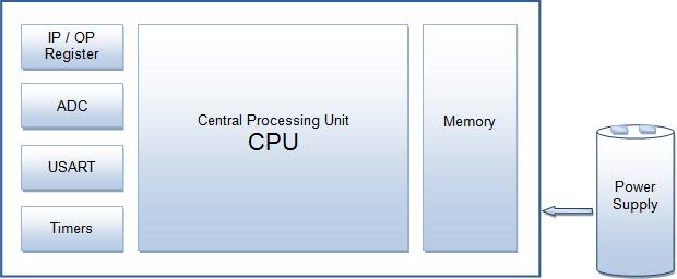
There are number of popular families of microcontrollers which are used in different applications as per their capability and feasibility to perform the desired task, most common of these are 8051, AVR and PIC microcontrollers. This article introduces the AVR family of microcontrollers.AVR was developed in the year 1996 by Atmel Corporation. AVR...
vast flume
Thx
knotty tiger
@vast flume it's one of the original Arduino MCUs (the 328P is used in the Uno), so lots of guides for the Arduino ecosystem will talk about it
 vast flume
I'm planning on using the ATMEGA328P-MMHR for my PCB, and in the datasheet it says that it has an internal calibrated oscillator

Does this mean that I don't need to add an external one? I am going to be communicating with a device over I2C, idk if that makes a difference
knotty tiger
vast flume
I'm planning on using the ATMEGA328P-MMHR for my PCB, and in the datasheet it sa...
it's an RC oscillator, so it has variations based on temperature and supply voltage. check the datasheet for tolerances. you can calibrate it more tightly either with a one-time calibration or active temperature compensation (with the built-in thermometer). I2C can be much more forgiving of clock frequency variation than start-stop async (UART) or USB
vast flume
Ok, I guess I'll still use an external one to be safe then
One more question, am I able to use this dc-dc converter as a voltage regulator, or do I need to also have a separate voltage regulator? https://www.digikey.com/en/products/detail/nisshinbo-micro-devices-inc/RP400N501A-TR-FE/10244946