#help-with-linux-sbcs
1 messages · Page 26 of 1
 half nexus
 hardy plaza
I think the problem (if the question is getting it into a thin package like a gum packet) is that you'd have to avoid using the GPIO pins since that's 12mm right there. The little PiTFT display isn't actually any thicker than the Pi Zero itself, so if you used wire to connect the two side by side you could keep the thickness to around 5mm.
 amber fulcrum
aaaah i see, that makes sense, i don't really have a good idea of what size a gum packet is because it really varies in the UK, the gum i buy comes loose in a box for example
hardy plaza
As an experiment I built a Pi Zero W and its tiny spy camera into a hollowed-out paperback book, with the camera on the spine. Very MI6-ish 😎 . I wired it for USB power but there would have been room for a small LiPo battery. The one issue with any of these kinds of installations that bears consideration is heat. If a Pi Zero W is not vented it will get pretty hot, pretty quickly.
hardy plaza
amber fulcrum
aaaah i see, that makes sense, i don't really have a good idea of what size a gu...
Off the top of my head I'd say a Trident gum packet is about 8mm thick. But I don't have one at hand to check.
amber fulcrum
are Pi Zero W's pretty good? ive been looking to pick up a Pi eventually, but student budget and all they're kinda expensive for me
hardy plaza
They're great little boards. The Pi Zero 2 W is a quad-core version with 512MB of memory, with WiFi for US$15. So if you can work in a relatively memory-constrained environment you still get multiple cores (whereas the other two Pi Zeros are single core).
Of course the biggest issue is that it's likely nobody will be buying any non Pi 4 models (any of the older 40nm silicon) aren't available at all, perhaps for as long as 52 weeks last I heard.
But where else can you get a proper Linux computer for $15?
amber fulcrum
I think i have a couple of Pi 2's around that i bought when i was a kid, but i've not really found a use for older Pi's
hardy plaza
amber fulcrum
I think i have a couple of Pi 2's around that i bought when i was a kid, but i'v...
Yeah, I have an 2011 era model. The newer ones are a lot more powerful and even have HDMI connectors on them so they can plugin to a full HD monitor.
If you use a Pi Zero as a console rather than desktop computer and remote ssh into it, it's often hard to tell you're not actually on a much larger Linux server. Great for those wanting to learn Linux, or programming or computer use on the command line. A bit limited with a desktop as you're kinda pushing the performance boundaries IMO. Though it does actually work fine, just a bit slow. No YouTube videos or Grand Theft Auto.
amber fulcrum
oooh good to know!! i don't really have any specific uses in mind for one yet, but it seems like such a neat little device that im sure i'd come up with something
hardy plaza
Yeah, we kinda take things like this for granted a bit, but they're really remarkably great little devices. I'm a big fan of the Pi Zero, have used them for lots of things, even put one inside my letterbox so I can see if I have any mail. It has a magnetic door sensor and an IR human detector which turns on a string of LEDs to light up the path at the front of the house (and thusly deters burglars methinks).
amber fulcrum
is the Pi Zero W 2 much of an upgrade?? i notice the 1 is a lot easier to get a hold of
hardy plaza
There's even 3 of these in stock if you're quick: https://www.adafruit.com/product/3579

Build your very own neighboor cam, desktop cam, or wildlife cam, or security cam, or...or... really any kind of camera! The Pimoroni OctoCam kit has everything* you'll need, ...
hardy plaza
amber fulcrum
is the Pi Zero W 2 much of an upgrade?? i notice the 1 is a lot easier to get a ...
It's four cores versus one. If your application doesn't benefit from that you'll not notice it so much.
amber fulcrum
oop my message disappeared
imma have to check back in a week or two and see if my UK supplier stocks them!!
cause it's a cool little kit
hardy plaza
I don't see them on the Pimoroni web site right now, wonder if they've been discontinued.
amber fulcrum
they;re out of stock on pimoroni but i use uhh
Pi hut
sometimes, because they tend to stock stuff that pimoroni doesn't have
hardy plaza
If you're looking for Raspberry Pis there aren't any, anywhere. I think Pi 4s are sometimes found, and Pi 400s. But the chip shortage has hit.
amber fulcrum
Oh yeah that's fair, Pihut tends to stock little things like the octocam type kits or arduino stuff, as well as the microbit
i like browsing it sometimes
they do sometimes list stuff that's just not in stock for a while though, still waiting to see if they get a lock picking kit back in stock
hardy plaza
It's kinda sad when the Pi Hut has no Pi.
amber fulcrum
a little!! i think the only Pi i can get from them is a 2gb 4b or a Pi Zero W 1
hardy plaza
Ah, yes. That's probably the only Raspberry Pi Zero W in the world right now.
amber fulcrum
gosh is it everything that's rare right now?? i assumed it was just the big models
hardy plaza
Actually, the Pi 4s are somewhat still available. It's all the older models that can't be found.
amber fulcrum
oh huh! i guess i didn't keep too up to date with the shortage, most of what i know was talking to the lab techs, they're trying to get a Pi Cluster going for the uni to use
 last bramble
anything i can use as a battery
for a portable deck
would a standard power bank with usb C be enough
amber fulcrum
I've seen decks with a couple of 26,000mAh power banks before, but it totally depends on ur usage
 faint sparrow
what's a deck, duck.
 turbid rivet
last bramble
would a standard power bank with usb C be enough
turbid rivet
last bramble
would a standard power bank with usb C be enough
A portable power bank is usually sufficient. Just make sure to test for strange behaviors before integrating one into your deck. I've heard of banks that timeout after a fixed duration, or cut power briefly when plugging the bank into a charger...
last bramble
turbid rivet
A portable power bank is usually sufficient. Just make sure to test for strange ...
alr
ill buy one from anker in that case
amber fulcrum
faint sparrow
what's a deck, duck.
i think if you google Pi Cyberdeck you'll get your answer
also thanks for bringing up decks!! i haven't thought about one in ages and now im writing a parts list :P
last bramble
faint sparrow
what's a deck, duck.
sorry didnt see this
its basically a tiny deck
look up the pi cyberdeck
its a good example of what im trying to refer to
amber fulcrum
what kind of screen are you thinking about using?
The official Pi 7" one is verrry tempting
faint sparrow
deck the halls
amber fulcrum
ooooh i see
 mystic light
most USB power banks timeout and cut off if their current draw is too low. I found one vendor Voltaic Systems that makes USB battery packs that are "always on"
amber fulcrum
Anker has a mode for low power devices like headphones
on some of their power banks
so im wondering if one of those would be suitable
 rotund pivot
there's a dongle to use with auto-shutoff power banks https://www.crowdsupply.com/pichanon-suwannathada/powerever
amber fulcrum
That’s pretty cool but I don’t think I can get one here sadly
 rugged kettle
Weird question, how can I take an iso image on an rpi via ssh? Due to ✨ reasons ✨ the SD card is currently difficult to get to
 umbral sable
rugged kettle
Weird question, how can I take an iso image on an rpi via ssh? Due to ✨ reasons ...
umbral sable
rugged kettle
Weird question, how can I take an iso image on an rpi via ssh? Due to ✨ reasons ...
That's kind of difficult, since if I understand you correctly, you want to re-image the Pi's SD Card while it's actually already booted and running from that drive. It's probably not impossible but it might involve booting into a RAM disk mode or something like that.
 digital scroll
Question so i'm trying to enable ssh on the raspberry pi imager and when i click use password authentication it doesnt allow me to put in a password so when i go to set it up on command prompt i have no idea what to put as the password
 vapid python
Try the default user: pi pswd: raspberry
digital scroll
now its saying it cant find a host name
digital scroll
asked if i wanted to put it under ecdsa, hit yes and now it wont let me type a password
 fickle shard
digital scroll
asked if i wanted to put it under ecdsa, hit yes and now it wont let me type a p...
fickle shard
digital scroll
asked if i wanted to put it under ecdsa, hit yes and now it wont let me type a p...
If your characters arent echoing back to you, that’s expected
amber fulcrum

The Pi Hut
This is a 5" Raspberry Pi LCD touchscreen with 800*480 resolution and 108×64.8mm display area. The product supports the Raspberry Pi DSI display interface and comes with a capacitive touch panel on its screen and supports 5 touchpoints. Features Capacitive Touchscreen, Support 5 TouchPoints. Raspberry DSI Direct Driver
Has anyone used a screen like this before?
The only connection to the Pi I can see on it is via ribbon cable? and I can’t tell if that’s the only connection I’d need
I haven’t actually used a Pi yet (waiting on it to be delivered)
hardy plaza
According to the wiki page for that product it gets its power and all signals from the ribbon cable.
https://wiki.dfrobot.com/5''TFT-Display_with_Touchscreen_V1.0_SKU_DFR0550
wiki:A 5 inches Raspberry Pi touchscreen with 800x480 resolution and DSI interface.
amber fulcrum
Oh nice!! I didn’t know it could supply enough power for a display like that, I saw a bigger one that needed a separate power connection so I was concerned
thanks
hardy plaza
I've used only SPI and HDMI displays myself but the DSI interface is native Pi and should work fine.
amber fulcrum
I was thinking of plugging in an e-ink display alongside this so I could have a no-power weather display so I wanted to make sure I wasn’t using any conflicting pins or anything
hardy plaza
You may note that the "touch screen" has only 5 touch points so it won't be functioning as a typical touch screen.
The e-ink displays probably are SPI?
I believe you can have as many as two SPI devices on a Pi. But since this display is DSI it's not taking up an SPI address anyway.
amber fulcrum
Yeah the one I’m looking at is just a

The Pi Hut
This is a tiny 1.02" E-Ink display module with a 128×80 resolution and embedded controller. The module communicates via an SPI interface (making it great for a number of different development boards such as the Raspberry Pi) and supports partial refresh. Due to the advantages like ultra-low power consumption, wide view
So I assume it’s just GPIO pins and a library
hardy plaza
Also, the doc page notes that the display will take up to 1.5A while operating so you'll need a power supply that can handle the combined current of all your devices.
e-ink displays typical take very low power.
amber fulcrum
fair, I was thinking of using a 26,850mA power pack I had laying about?
Oh wait that should not be a 5
hardy plaza
amber fulcrum
fair, I was thinking of using a 26,850mA power pack I had laying about?
That's a rating in milliamp-hours, not maximum current capacity.
amber fulcrum
oh right yeah it’s 2.1A
I was honestly more worried about charge time, I forgot about capacity 😅
hardy plaza
So, you'd add up the max current of your Pi and all your devices and add about 20% for safety' sake.
amber fulcrum
Ah yeah that’s probably an issue since I think the Pi is like, 1.5A max
hardy plaza
If your power supply isn't capable of supplying enough juice it will brown out, dropping voltage until the Pi resets. A Pi actually needs 5.1 volts so a 5 volt supply, while it works, is already a bit lower than what is ideal.
The official Raspberry Pi power supplies are 5.1 volts, but clearly a lot of people use 5v USB power supplies, and so long as they're beefy enough they generally work. But I'd say a significant majority of problems people report here are due to power supply issues.
amber fulcrum
I guess I might have to look for a smaller display, not sure any powerbank I can find will be happy with the display
Oh hold on
hardy plaza
Or if it's okay with your requirements, find one that has a separate power jack. Then the Pi isn't affected by the display, it just sends signals.
amber fulcrum
Where did you get 1.5A from?
hardy plaza
The wiki page for the display.
amber fulcrum
hmm the pi store lists 320mA as it’s maximum operating
hardy plaza
The FAQ section: "Please check Raspberry Pi’s power. The current of the touchscreen should be at least 1.5A during its work."
Yeah, I see that. A bit of a contradiction clearly.
amber fulcrum
Curious
hardy plaza
I sometimes find DFRobot's stuff a bit mystifying.
amber fulcrum
I wonder if it’s talking about like, the current of the Pi and the Display?
The pi seems to like to chug on 1.3A
hardy plaza
That's not what it says but maybe that's what they mean. But that would depend entirely on the Pi. A Pi Zero has a very much smaller power requirement than a Pi 4.
amber fulcrum
Would the display be able to pull 1.5A from the Pi even
hardy plaza
Yeah, in theory.
amber fulcrum
huh okay
hardy plaza
But that does sound dodgy I agree.
amber fulcrum
I might see if I can find any mention about it online,
hardy plaza
I don't know what the maximum current the DSI can supply. I'm sure that'll be in the Raspberry Pi specifications somewhere though.
Yeah, search on "raspberry pi dsi maximum current"
Interestingly, it says "the DSI ports power lines are dimensioned ONLY for the power requirement of the camera logic NOTHING ELSE!"
amber fulcrum
hmmm
I might see if I can get a waveshare display or something instead
This one seems way dodgy
hardy plaza
Furthermore (same page):
"The PMIC chip appears capable of supplying 3V3 at 1A5 though whether it can or not on a Pi is unknown to me. That 3V3 goes to other parts of the boards, and I would expect to the SoC and other components not shown on the reduced circuit, so it is difficult to say how much current can be drawn from 3V3 on a Pi.
We don't know how much the PMIC can actually supply, we don't know how much the board uses, and that will vary depending on use, so we don't know what capacity is spare, and that will be reduced if cameras, displays and other things are connected. The amount one can draw from any 3V3 pin is not officially stated anywhere."
amber fulcrum

The Pi Hut
Apart from the Official Raspberry Pi Touchscreen Display, we don't often see many DSI interface displays for the Raspberry Pi. This capacitive touch display is one of those rare treasures, using the simple DSI ribbon cable connection to the Raspberry Pi - avoiding bulky HDMI solutions for an altogether more compact dis
This one looks a bit easier to work with 😅
It also uses the ribbon cable surprisingly
hardy plaza
On the other hand, if "bulk" isn't an issue for you, you might consider an HDMI display. You can plug a Pi into any HDMI display but there are some smaller ones available and the display quality will be very high. And they generally will have their own power supply.
amber fulcrum
unfortunately bulk is an issue
hardy plaza
yeah, the HDMI cables are undeniably bulky.
amber fulcrum
yeah it’s a shame because I’d rather use a HDMI, but the ribbon cable seems to be an easy out for me
they’re saying the display is 700mA ~ 750mA
which unfortunately cuts it close for me mmm
hardy plaza
I guess you can go with the notion that they're selling this as a functional product, so hopefully it just works.
amber fulcrum
yeah that would be ideal
hardy plaza
It looks like the DFRobot and PiHut are the same display, same "5-point touchscreen" it seems. It looks like the PiHut one is sourced from Waveshare, who I've bought a robot kit from.
amber fulcrum
yeah, the 5 point is kinda weird to work with
I’d honestly rather just not have a touch screen
hardy plaza
Their robot kits are well made so I'd say the Waveshare stuff is likely generally pretty good.
hardy plaza
amber fulcrum
I’d honestly rather just not have a touch screen
Well, you can certainly ignore it.
amber fulcrum

The Pi Hut
Its a mini panel-mountable HDMI monitor! So small and simple, you can use this display with any computer that has HDMI output, and the shape makes it easy to attach to a case or rail. This backpack features the TFP401 for decoding video, and includes the attached display so its plug-n-play.The TFP401 is a beefy DVI/HDM
I’m wondering if the Ada fruit one is worth going with since the documentation is just. Better
They even list current draw with the backlight at half settings but I’d have to contend with the bulky hdmi
And I imagine even less than the other ones because it’s not capacitive
hardy plaza
One thing about HDMI is that your cable may be bulky but it's durable. Ribbon cables are very fragile, as are the Pi's on-board connectors. That may not be an issue for your application, but you don't want to be connecting and disconnecting the ribbon cable a lot.
amber fulcrum
that’s a fair point, especially because I’d rather not open up the box to have to fix stuff like that, and it might get moved around a lot
hardy plaza
The little black DSI lock bracket is very prone to snapping. I've broken a couple myself.
I think the ribbon cable is fine for permanent installations inside of enclosures, a once-applied kind of thing. Not at all suitable for portable applications or anywhere the ribbon cable may be under any stress at all.
amber fulcrum
that makes sense, portable is the goal for me so

This is the box I’m planning on using
It’s 316x195x53mm
The main constraint for me is vertical size
but I wanna work with it
hardy plaza
I'm guessing that 53mm is the external height dimension, not the internal?
hardy plaza
What all are you trying to fit inside? That's a pretty big box.
amber fulcrum
A Pi, the screen, a power bank, an E-ink display, and maybe some funky switches and buttons
Oh and a 30mm fan
Oh a keyboard on the lid too
hardy plaza
Well, one thing I've done is mock up the objects using cardboard and tape, and put them inside a container that's the planned size, shift them around to get a feel for how they'd fit.
amber fulcrum
hmmm that’s smart, wish I hadn’t just passed over of a bunch of boxes
also wish I hadn’t left my callipers in the lab oops
hardy plaza
bit of cardboard and tape is all you need.
Doesn't have to be perfectly accurate, just to give you an idea.
amber fulcrum
maybe an 212x140x47mm ID would be more suitable then
hardy plaza
Honestly, mock it up in cardboard and you'll have a much better idea. I don't know about you, but for me having the physical objects at hand really helps.
amber fulcrum
It really helps me too, I just wish I had all the components in front of me for it 😅
Little paper mock-up, I think I’m gonna have more than enough space you’re right,

Keyboard could be a concern but I have a Logitech one I could slot in instead in a pinch
hardy plaza
Not sure what you like in keyboards but I have one of these, which work pretty well for a small keyboard. https://www.adafruit.com/product/2876

The quick brown fox jumps over the lazy dog. The quick brown fox jumps over the lazy dog. The quick brown fox - sorry! We were practicing our typing ON THIS AWESOME KEYBOARD.With ...
If you don't need the trackpad this one is nice too: https://www.adafruit.com/product/1738

Add a good quality, slim chiclet keyboard as well as an optical mouse to your Raspberry Pi, Beagle Bone Black or other mini-computer with this wireless combo set. Best of all, it only uses a ...
amber fulcrum
oooh the one with the trackpad looks nice!!
hardy plaza
amber fulcrum
oooh the one with the trackpad looks nice!!
I have an older white version of that. It works reasonably well though the keys are small. If you don't need the trackpad the keys on the other one are a bit better.
It's the keyboard I used to type directly into the console on my robots since it's radio-connected and works anywhere, and doesn't need Bluetooth.
last bramble
are there any power bank models that work with the raspberry pi zero w
since i was previouslytold that some power banks arent too reliable for a pi
amber fulcrum
The solution I was given for those power banks is to solder a 100 ohm resistor across a USB cable and plug it in
 wraith grove
adding a constant draw of 50 mA, according to my potentially erroneous math
amber fulcrum
Yeah I think that’s the minimum current that it wants to stay out of sleep mode
wraith grove
my naive math suggests that is 0.25 watts the resistor is burning, fancier math is saying other things, but looks weird and doesn't overtly make sense to me :-)
last bramble
i cheaped out on the power bank
i ordered a screen, a starter kit, a power brick and the arduino starter kit
hardy plaza
amber fulcrum
The solution I was given for those power banks is to solder a 100 ohm resistor a...
Eek, that sounds like not so good an idea, especially the effect on battery life. I'm sorry I can't be more help, but a couple of years ago I had a small robot with a power bank with this problem, and I dug around on the Web until I found a circuit, which is lost in the sands of time. I still have the part I made, which has two transistors, two resistors and a cap. Plugged across 5v and ground it keeps the battery awake but at much less than 50mA.

But sorry, no schematic 😑
But if you search on "usb power bank keep alive" you'll likely find something.
amber fulcrum
ooh okay!! If I find I have a problem with battery life I will seek this out, but for now I have some USBs with the breadboardy connectors so I can literally just slot a resistor in there as a quick fix
last bramble
not sure what to use as a good source of battery for my raspberry pi
want something small enough but not too small
so that it still lasts a few hours
turbid rivet
last bramble
not sure what to use as a good source of battery for my raspberry pi
https://www.tindie.com/stores/pisugar/ is neither the smallest, cheapest, nor longest-lasting, but it is designed specifically for the Pi, so there are some functional advantages to this over a traditional power bank.
 last bramble
turbid rivet
https://www.tindie.com/stores/pisugar/ is neither the smallest, cheapest, nor lo...
last bramble
turbid rivet
https://www.tindie.com/stores/pisugar/ is neither the smallest, cheapest, nor lo...
alr ty
mystic light
@amber fulcrum if you end up needing an 'always on' power bank, this is what I bought to power my portable microcontroller stuff: https://voltaicsystems.com/v25/

Voltaic Systems
Voltaic Systems designs high-performance solar chargers and complete power solutions for electronics and IoT applications.
amber fulcrum
The voltaic bank does look nice, and I have been considering one, shame I can’t find a UK supplier though
wraith grove
I wonder if a large enough capacitor can hold the fort until enough current is needed to wake the bank? Too simple?
amber fulcrum
Maybe a film capacitor could?
An electrolytic capacitors doesn’t hold charge for a very long time I don’t think
hardy plaza
No capacitors hold a charge for significantly longer than others based on type, only rated capacitance. Electrolytic capacitors just happen to be a type that is available in very large sizes. But even a huge capacitor isn't going to keep a power bank awake as the bank relies on current draw, and once the capacitor is full it won't draw any further current. And it will discharge (on a curve) below the battery threshold almost immediately.
amber fulcrum
I think the capacitor was to wake the Pi and get it to start drawing current
Rather than wake the bank
hardy plaza
Hmm. I don't see how that would work.
amber fulcrum
Yeah thinking about how the bank works neither do I
 wintry steeple
does anyone know why my SenseHat on raspberry pi only sends 3 sets of data( temp, humidity and pressure) for 3 times and connection error occurs?
im trying to send the data to adafruit io
 humble marsh
wintry steeple
does anyone know why my SenseHat on raspberry pi only sends 3 sets of data( temp...
humble marsh
wintry steeple
does anyone know why my SenseHat on raspberry pi only sends 3 sets of data( temp...
we'd need to see your code. Make sure you are not redoing the whole connection in the loop. Also note there is rate-limiting on the free version of adafruit.io
mystic light
I think power banks have a 'timeout', so if you switch on a current load every few seconds or so for ~1-10ms, maybe that would keep it from shutting off while having a very low overall power draw
amber fulcrum
Hey so, I was thinking of using a switch to toggle my Pi on/off, how would I go about that? I haven’t got a Pi in front of me yet so I don’t understand the software too well
turbid rivet
amber fulcrum
Hey so, I was thinking of using a switch to toggle my Pi on/off, how would I go ...
For straight power on/power off, https://vilros.com/products/vilros-usb-c-5v-3a-power-supply-with-switch-designed-for-pi-4?variant=29404996698206¤cy=USD&utm_medium=product_sync&utm_source=google&utm_content=sag_organic&utm_campaign=sag_organic would just cut power. Not good for the Pi's SD/SSD, but it's the simplest way to do it.
For power on/shutdown, you would have to do some configuration software-side to enable a shutdown button. Plenty of tutorials if you google "Pi shutdown button" and browse the results. Usually a momentary switch connected to GPIO, so that the software can decide what to do with different kinds of presses in different states.
 olive haven
This article looks useful, including references to how it all works: https://scribles.net/adding-power-switch-on-raspberry-pi/
amber fulcrum
Ooh perfect, thanks to both of you!!
I was looking at an SPDT or something like this

Might end up just being the standard SPDT because looking at the dimensions that switch is bigger than my case lmao
 abstract mason
Hello Everyone, I'm using a ADS1115, and the adafruit library for it. I want to compare a value that I got from the device with an int value like 1. But it's not working, when I try to make my variable an int, the error below happens. Does anyone know what can I do? Ps: Sorry for my english..

I've tried int(pressao), but still doesn't work
turbid rivet
abstract mason
Hello Everyone, I'm using a ADS1115, and the adafruit library for it. I want to ...
Try pressao.value instead?
abstract mason
Already found my mistake man, thanks for your help!!!
 zealous seal
If anyones looking, looks like Microcenter has Pi 4s in stock and they require going to the story to buy them (no online ordering at all - even for pickup)
 agile wigeon
mystic light
<@!670329623724163083> if you end up needing an 'always on' power bank, this is ...
agile wigeon
mystic light
<@!670329623724163083> if you end up needing an 'always on' power bank, this is ...
is there a smaller version of this?
mystic light
that's the smallest by that vendor, not sure if other vendors have smaller options
 blissful jolt
anyone familiar with RP2040 C SDK? Esp about DMA I2C peripheral transfers?
 unborn rapids
When I try to start steam link on my raspberry pi 4, I get the following error message:
X11 is not supported on this version of Raspberry pi. You can run on the console or download Raspberry Pi Buster.
Can someone help me ? 🙂

on the Raspberry OS
amber fulcrum
you're on bullseye right?
i think bullseye doesn't have a feature that steamlink requires
the Buster branch does though which is why it's asking you to run that instead
faint sparrow
Buster is old.
Wonder what X11 means here.
We had XFree86, we had X.org.
My friend rants about that new one.
Vanity or something. ;)
Wayland (same thing!)
Since the RPi4 is an SOC I don't know what they did for its video capacity.
Probably not X.org though.
amber fulcrum
not entirely sure what it means, but it seems to have some relation to hardware acceleration?
olive haven
X11 is the X Window System, "a windowing system for bitmap displays, common on Unix-like operating systems." (https://en.wikipedia.org/wiki/X_Window_System)
faint sparrow
What you would do is stash the SD card. Get another. Install Buster on that other SD card.
hardy plaza
olive haven
X11 is the X Window System, "a windowing system for bitmap displays, common on U...
I believe the Pi desktop is using X windows
olive haven
Apparently not in Bullseye, at least on the 4 -- that was the issue
olive haven
Yes, Wayland "Desktops in Linux have always been based on the X Window System, usually just referred to as X. This is what provides the basic services of a window environment – drawing windows, moving them around, managing the mouse pointer and so on. But X is now very old technology – it was first released in 1984 – and while it has served admirably for nearly 40 years, some desktop environments are now using replacements. The most popular of these is a system called Wayland, which has recently become the window system used by Ubuntu.
We are still quite a long way from switching Raspberry Pi OS to Wayland, but one of its requirements is a Wayland-compatible compositing window manager, and using mutter is the first step on this path." https://www.raspberrypi.com/news/raspberry-pi-os-debian-bullseye/
hardy plaza
olive haven
Apparently not in Bullseye, at least on the 4 -- that was the issue
So if one is using an alternative OS for a Raspberry Pi it's possible that it's based on Wayland, but the Raspberry Pi OS itself is still X based.
This wouldn't so far as I know be different across different Pi hardware models, it is specific to the OS itself.
 west sierra
Ah, so they are using Mutter as WM.
olive haven
Someone (@unborn rapids) above tried to run Steamlink on a 4 running Bullseye and got this message "X11 is not supported on this version of Raspberry pi. You can run on the console or downgrade to Raspberry Pi Buster." So something it wants isn't available.
hardy plaza
This just run on a Pi 3 B+ using the latest 64 bit OS:
☻ dpkg -l |grep xserver-xorg-core
ii  xserver-xorg-core                    2:1.20.11-1+rpt1+deb11u1         arm64        Xorg X server - core server
...and this just run on a Pi 4 using the same 64 bit OS (same SD card):
 ☻ dpkg -l |grep xserver-xorg-core
ii  xserver-xorg-core                    2:1.20.11-1+rpt1                 armhf        Xorg X server - core server
 ☻ cat /etc/os-release
PRETTY_NAME="Raspbian GNU/Linux 11 (bullseye)"
NAME="Raspbian GNU/Linux"
VERSION_ID="11"
VERSION="11 (bullseye)"
VERSION_CODENAME=bullseye
ID=raspbian
ID_LIKE=debian
HOME_URL="http://www.raspbian.org/"
SUPPORT_URL="http://www.raspbian.org/RaspbianForums"
BUG_REPORT_URL="http://www.raspbian.org/RaspbianBugs"
Though it is telling that the error message uses the term "Raspbian". I don't know how hard the team has tried to expunge the old name of the OS from its strings, but it hasn't been called Raspbian for awhile now.
last bramble
since im like one of the few people that dont own a 3d printer
what can i use as housing
thinking of using this old box shaped wifi router as my pi's housing
but im not sure how inconvinient it is in comparison to just owning a 3d printer
olive haven
I use these https://www.adafruit.com/product/2258 for 2s and 3s, and these https://www.adafruit.com/product/3252 for Zeros. They're both well-designed and don't block anything important.
hardy plaza
last bramble
thinking of using this old box shaped wifi router as my pi's housing
One thing you'll probably want to consider on anything but a Pi Zero that's not under much of a workload (as they run pretty cool then), is some kind of ventilation, or some way of thermally connecting the Pi's CPU to the enclosure so it can stay cool. Unless you're running it hard you probably won't need a fan but you will need to have some even ambient airflow over the board.
amber fulcrum
does the Pi 4 have a similar thing?
was thinking of getting a heatsink but i could try and fudge a 25mm fan into my case
hardy plaza
amber fulcrum
does the Pi 4 have a similar thing?
If it's under any load at all a Pi 4 runs pretty hot. I'd recommend at very least heatsinks on the CPU, Ethernet controller and WiFi controller. There's cheap little three piece kits for this. A fan on its own isn't very helpful without the heatsinks — what you're doing is effectively increasing the surface area of the device so the air can cool it. The little 25mm or 30mm square fans work wonders in ventilating an enclosure.
amber fulcrum
okay, thank you!

 amber fulcrum
glad they come self-adhesive, no idea where my thermal paste is
hardy plaza
Yeah, I have a small tube of that somewhere in my house, but it would probably mean tearing the house down to find it.
amber fulcrum
dont know if mines even in this house
could have gotten lost during a move

im thinking one of these would be nice too
just have to make sure i mount the fan in the right direction :P
hardy plaza
Actually, it doesn't matter so much, it would still do a nice job cooling, but you don't want your enclosure to act as a small vacuum cleaner. It would eventually fill with dust and cat hair.
amber fulcrum
aah right, is there some design work i can do to avoid turning it into that?
hardy plaza
Don't own cats.
hardy plaza
All of my computers are full of cat hair.
amber fulcrum
so its less of a design thing and more of a
prepare to feather dust my enclosure
thing
hardy plaza
I vacuum mine, as a feather duster just lofts the cat hair so it can end up on your dinner.
But now we're waay off topic.
And it's dinner time, I just reminded myself.
amber fulcrum
hey it's good tips for care of my pi! it's breakfast time here so im gonna go grab some food myselff
last bramble
hardy plaza
One thing you'll probably want to consider on anything but a Pi Zero that's not ...
ill keep that in mind
im gonna use a heatsink on the pi zero and maybe cut some holes for ventilation
 fierce spire
Where do Variables get saved while the program is running? So is there a limit on how long for example a simple list can be. (I want to first save collected sensor-data in a list because I think it is too fast for my pi zero to directly write them into a text file) Thanks a lot!
hardy plaza
fierce spire
Where do Variables get saved while the program is running? So is there a limit o...
You don't mention which programming language you're using, but generally speaking variables are held in memory. If, for example, you're using Python you can get the free memory using the psutil library, as in:
>>> import psutil
>>> psutil.virtual_memory()
svmem(total=16717422592, available=5376126976, percent=67.8, used=10359984128, free=1831890944, active=7191916544, inactive=2325667840, buffers=525037568, cached=4000509952, shared=626225152)
This will let you know if you're using up too much.
 dry galleon
So ive just installed NodeRed and Mosquitto on my raspberry pi. Ive subscribet to home/test on my pi but when i send something to it via the MQTT node in NodeRed nothing happens and the node says its connecting.

 faint sparrow
unborn rapids
When I try to start steam link on my raspberry pi 4, I get the following error m...
faint sparrow
unborn rapids
When I try to start steam link on my raspberry pi 4, I get the following error m...
Sounds like it means that xorg isn't supported by steam link unless you downgrade to Buster (from Bullseye).
Then it would be supported.
They offer an alternate route - use the console.
agile wigeon
is a 3.7v 2200mAh battery enough to power a raspberry pi 0 with a display for a decent amount of time?
 civic rune
Hmm, I think a pi needs 5V? I'm not 100% though
Yeah the battery packs I'm seeing are 5V
agile wigeon
oh
amber fulcrum
also 2200mAH isn't a lot, i did some shoddy maths and i think?? you'd probably get 1-2 hours depending on what the Pi is doing
nevermind the display
im using a 20,000mAH battery with my Pi + Display
agile wigeon
amber fulcrum
im using a 20,000mAH battery with my Pi + Display
how long does it last with the battery?
amber fulcrum
Can't really say yet, numbers get a fair bit bigger and im not sure im as confident doing the math for it
hardy plaza
amber fulcrum
Can't really say yet, numbers get a fair bit bigger and im not sure im as confid...
A battery's rated capacity isn't what it actually delivers, but you can back-of-napkin estimate. e.g., if your Pi uses 2A and your battery capacity is 2000mAh (2Ah), then your Pi will run for about an hour. And a Pi requires 5.1 volts though it will run at 5v.
...though it's important also to note that a battery used as a charger still charges until it goes below its minimum voltage and (hopefully) shuts itself off. LiPo batteries should not be permitted to run to zero. But the lower limit on a Pi is about 4.75 volts, so the Pi will shut down (reset but not recover) when the battery voltage goes below that level. That may be well before the value indicated by the rated capacity. There are usage curves for batteries and you'd have to see the curve of the battery to see at what point it goes below 4.75 volts to know how much actual running time you have. If the manufacturer doesn't publish a curve then you get to guess.
So when I said a Pi that uses 2A would run on a 2Ah battery for an hour, I was lying. 😋
amber fulcrum
Alright, good to know, thank you! Most of my maths was okay but I forgot battery voltage dipped 😅
If I’m using a power bank and not a straight LiPo, it’ll probably have circuitry to keep the voltage at 5v right?
hardy plaza
amber fulcrum
If I’m using a power bank and not a straight LiPo, it’ll probably have circuitry...
It may have circuitry to keep the voltage from being above 5v, but of course once the battery dips below a certain level it won't supply 5v. It's also important to note that not all power banks actually supply 5v, some (designed as chargers) may supply more than a Pi can handle. See the section "Overpowering Your Pi" on:
https://www.twilio.com/blog/3-ways-brick-raspberry-pi

Twilio Blog
Does your desk need another paperweight? Learn three easy ways to ruin your Raspberry Pi forever.
The power brick linked from the article is listed as a "fast charger" and produces 7v.
amber fulcrum
ooof okay
hardy plaza
Most USB power banks will tell you what the output voltage is, at least mainstream brand ones.
Probably the best way to find out how long a specific Pi-plus-peripherals will last on a given battery is to write a quick Python program that writes to the system log:
syslog. syslog('message')
and then start that program from a full charge and then it run until the Pi powers off. Then look at the system log to see when it actually did stop logging.
 fickle spoke
hey so I just got a POE+ hat for my pi4 and when i plug it in, there's a screeching noise, followed by the ACT led turning off. do I have a defective hat?
fickle spoke
nevermind, it's working now.
 grave condor
hello there, first time here. when I connect my raspberry pi pico to my computer, it never runs the script i wrote on it in the beginning. it always opens up the CIRCUITPYTHON folder. how do i fix it?
civic rune
grave condor
hello there, first time here. when I connect my raspberry pi pico to my computer...
Hey, that's the RP2040 board, right? I think the right spot for your question is #help-with-projects, #help-with-circuitpython, or #general-tech. This channel is more for the traditional single board computers from the raspberry pi folks 🙂
grave condor
thank you
civic rune
np
 pliant pebble
Can I take screenshots on a pi with no desktop??
hardy plaza
pliant pebble
Can I take screenshots on a pi with no desktop??
Is that a trick question?
No desktop, no screenshots. If you want a screenshot of a console session you'd need to open a terminal window in a desktop session and do a screenshot of the window.
olive haven
pliant pebble
Can I take screenshots on a pi with no desktop??
I'm not quite sure what you're asking, but it is possible to run a VNC connection to a Raspi (running the desktop OS, not Lite) and get a desktop that way, even if you don't have a display connected to the Pi.
hardy plaza
olive haven
I'm not quite sure what you're asking, but it is possible to run a VNC connectio...
But to be clear one cannot take a screenshot if there is no screen.
turbid rivet
pliant pebble
Can I take screenshots on a pi with no desktop??
If you have a desktop-less setup, you could capture the screenshots of an SSH session on another device with a desktop?
faint sparrow
pliant pebble
hardy plaza
Is that a trick question?
Mmmkay
pliant pebble
hardy plaza
But to be clear one cannot take a screenshot if there is no screen.
I have a display, but I have no desktop.
I have command-line only
pliant pebble
turbid rivet
If you have a desktop-less setup, you could capture the screenshots of an SSH se...
Great, thanks
pliant pebble
faint sparrow
*<https://askubuntu.com/questions/1027872/how-to-have-a-terminal-mirrored-onto-a...
Thanks
faint sparrow
I built a RPi3 based ebook reader for my mother; it had no window manager so she couldn't easily misoperate it. ;)
It just launched FBReader with no window decorations.
Ctrl + Alt + Fn still worked but she didn't know about that. ;)
(so I could gain access for maintenance)
I ended up sitting next to her with a second (Infrared) remote control (which presents as a USB keyboard to the host PC).
She'd hit the spacebar on the wireless keyboard I setup for her, when she wanted to turn the page.
I'd turn back a page or two after she did so (unbeknownst to her) .. because she didn't learn the timing on the space bar and held it down too long, enagaging keyboard auto-repeat.
Raspberry Pi Foundation usually will not supply a person to sit next to you.
pliant pebble
haha
faint sparrow
why are all of my channels like this? (I have one thing connected on ch7, im using the simpletest.py from https://github.com/adafruit/Adafruit_Python_MCP3008 examples)


GitHub
Python code to use the MCP3008 analog to digital converter with a Raspberry Pi or BeagleBone black. - GitHub - adafruit/Adafruit_Python_MCP3008: Python code to use the MCP3008 analog to digital con...
my rpi to mcp wiring includes:
RPI - MCP
3.3V - VRef
GND - AGND
SCLK - CLK
MISO - DOUT
MOSI - DIN
CE0 - CS
GND - DGND```and im using the raspberry pi 4b
faint sparrow
faint sparrow
why are all of my channels like this? (I have one thing connected on ch7, im usi...
is this because maybe my channel 7 data is just not working?
like the external source, not the board?
 steady rose
if the other channels are not connected to anything, then they can read noise
and just fyi - the library you linked is deprecated, readme has link to current one
faint sparrow
oh lol thanks
i noticed that earlier but for some reason i thought i migrated to the new code? im kinda dumb lol
faint sparrow
faint sparrow
why are all of my channels like this? (I have one thing connected on ch7, im usi...
i have the same test running and it shows the same thing, ill probably try to just check with another analog device or smt, thanks for the help tho
 honest maple
Hey folks.
I am working on a project I want to make portable and I have some experience with circuitry but I have never made a PCB for instance. I wonder if someone could point me in the right direction to answer a few questions and plan this build.
TLDR I need an AC power supply to a power + charging circuit to run a Pi + accessories
- I have a list of parts and USB accessories, but I don't know the power consumption of most of these. How can I measure the power consumption of the USB wifi card for instance, to better plan my needed battery capacity?
- I will need a battery source, I am assuming 18650's and a charging circuit that would allow me to charge + work directly off power.
- I am afraid of what I do not know here, so while I am looking at different charging IC's if anyone has any input on charging + direct power I would appreciate it.
- What safety features do I need to consider and where can I find more of this info?
Lastly, I need to power several separate devices, so this circuit must provide at least four but ideal 5-6 powered USB ports. See #1, I am not sure of the total amperage yet. - It would be nice to physically switch on and off USB ports to save power.
There is a 60W 6-Port USB charging hub on Amazon for $20, using AC power of course. If maybe a charging circuit could be added to it that would be amazing but I imagine maybe difficult if the transformer isn't separate.
There may be some slightly easier ways to do this if I assume charging via USB-C
 mint leaf
I borrowed the oscilloscope, and after some YouTube tutorials, I got everything up and running. With this tool, I found the “problem,” but not the “cause”. Now I am very stumped. So here is the deal. As a refresh, I am working with a Raspberry Pi 4B. I am trying to use PWM from pin 19. Originally, I launched into what I was trying to run and whatnot, but by using the scope, I found my problem is in the PWM signal itself. HERE IS WHAT I AM SEEING: the PWM signal will be at my set percentage (in my example, a 75% duty cycle). For the entire time the PWM signal is being generated, the signal is doing one of two things: 1) staying at the duty cycle I set it at, or 2) switching quickly between two different duty cycles (or a small range of duty cycles), generating the anomaly in my system. To give further explanation, I will post pictures of the O-scope reading.
This video is of the change taking place. It is operating at my set duty cycle, then switches to the “quickly changing duty cycles” thing that I don’t want.

This picture is a snapshot of the upper side of the “random switching duty cycle” with measurements.

This picture is the lower side, with measurements.
This picture is just a screenshot of the anomaly, in case the video doesn’t provide enough information. It is switching so fast, that when the scope is constantly measuring, it appears as many lines on the upper side.

I have observed this unstable signal on multiple (two) Raspberry Pi’s (both 4B). This happens on a raw 3.3V signal AND a stepped up 5V signal. What is observed on the scope is the 5V signal. I only mention this because stepping up the signal was our first try at fixing the problem.
For informational purposes, here is the actual project itself, just so you see what I am working on. I call it the King of Kings TechBed: a bed frame of natural wooden appearance that integrates modern technologies, including Adafruit RBGW neopixel lights, Vision Home Theatre surround sound system, relay controlled lamps, relay controlled tri-tiered wireless chargers (smartphone, wireless earbuds, Apple Watch), headboard cooling fans in the headboard, and a mini fridge. I’m an electro-mechanical engineer, and this was my senior project. The issues with the PWM signal for the fans is the last problem I need to solve.
 hardy plaza
mint leaf
This picture is just a screenshot of the anomaly, in case the video doesn’t prov...
hardy plaza
mint leaf
This picture is just a screenshot of the anomaly, in case the video doesn’t prov...
Well, I can't fault you for providing a lack of information but I don't really have any insights into the cause either, except to say that you're doing your PWM from a Raspberry Pi, which is a Linux time-sharing computer. I can't off the top of my head remember if the PWM is using a hardware or software clock, or whether it's affected by system load. And if and how you're running your program in Python whether that might affect PWM if it's not a hardware PWM.
So the only way I can suggest searching for that cause is to isolate the problem, perhaps by trying to run the PWM on a dedicated MCU to see if it's Pi-related or not, or somehow more hardware-specific.
 midnight sage
I'm gonna work on a BMC64 soon and I would love to simulate that Datasette port to the Pi 3 B+ what pins of the GIPO I need to connect to make the actual datasette talk to the Pi?
last bramble
trying to do a headless raspberry pi setup
i cant seem to ping or ssh into my pi
and all its showing is a red light
so im not sure whats happening here
olive haven
@last bramble Which Pi? How are you connecting -- wifi? I've found using Imager is the best & easiest way to get wifi & ssh set up.
last bramble
olive haven
<@!880036918451142737> Which Pi? How are you connecting -- wifi? I've found us...
raspberry pi 4 model b
i connected the wifi through the pi imager
and for some reason it wont pick up my pi's hostname when i ping it
sorry for late response btw
olive haven
You're trying to ping whatever.local?
olive haven
Try it with .local
last bramble
olive haven
Try it with .local
do i need to wait for my pi to start up
or do it now?
and when i do ping, i get the usual "name or service not known" error
olive haven
I usually wait till the disk activity light calms down a bit, then try it
last bramble
olive haven
I usually wait till the disk activity light calms down a bit, then try it
you mean the green light?
olive haven
What kind of computer are you pinging from?
olive haven
I don't have a 4 so I don't know what color lights it has.
last bramble
and i still get the "name or service not known" error
olive haven
The .local thing is ZeroConfig (or Bonjour, though I think just Apple calls it that.) You should see if that's a service that's enabled or that you can enable.
(I've never configured it on a Linux, so can't help with the specifics.)
last bramble
my only option is to wait for my microhdmi adapter to arrive so i can find out whats actually going on
olive haven
The only glitch like this that i've run into is when I configured wifi to try to connect to the 5G band of my router rather than the 2.4G -- the 3 and Zero at least only like 2.4
last bramble
i think ill just wait for my micro hdmi adapter to arrive rather than doing a headless setup now
olive haven
(I've been trying to get a 4, but that's kinda hardthese days)
last bramble
olive haven
(I've been trying to get a 4, but that's *kinda hard*these days)
true
it took ages to find one
for me
faint sparrow
Not at all. Just gotta be able to pay $7000.00! <laugh>
olive haven
I got mail from Adafruit that they were back in stock, but didn't see the mail until an hour later -- all gone.
faint sparrow
I really wish they'd do a "pre-order" rather than a email list. Be nice to put the money in and be queued to get one.
last bramble
i got mine from a nearby store
olive haven
yeah, that'd be nice. (For $7K I'd get 2-3 Macbook Pros...)
The local MicroCenter had them for a few hours last weekend, but I missed out on that.
faint sparrow
I really wish we could get chips up to full speed and get back to normal.
olive haven
Yep. I've seen a few estimates like "maybe in 2023"
The pandemic just shut down Shenzhen.
wraith grove
on linux if you're sure the pi is on the network you can
nmap 192.168.1.* -p22 # adjusting the IP numbers to match your network
and find just about everything on the network with an ssh port
they will be marked as open if it has ssh running
last bramble
i switched to my windows install to see if anything worked
used angryipscanner
and still wont pick up my raspberry pi
for whatever reason
last bramble
nevermind, found out what the issue is
olive haven
last bramble
nevermind, found out what the issue is
Out of curiosity, what was it?
last bramble
olive haven
Out of curiosity, what was it?
the hostname wouldnt show up
so it took me a bit to find the raspberry pi's ip address
then used that instead of the hostname
 silk tapir
My 3 died, keeps undervolting on the stock power supply, and I can't find rpis anywhere
Even another 3 would be fine at this point
But I would like a 4
 fickle shale
Today I found that a fresh install of Raspberry pi OS lite comes with python 3 and python 2.
Is there a way to make python 2 default?
civic rune
Just curious, why would you want to?
fickle shale
old tutorial
civic rune
Ahh
fickle shale
I tried it with python 3 but it made errors
Maybe there's a way to call python 2 instead of python 3 in the command line
 woven cargo
I am trying to display a count value in a loop on a raspberry pi zero. It works but when it displays multiple lines of it updating the count value, the pi lags significantly. Is there a way to code it to where is will just update a single line versus printing a new line everytime. It is counting the number of steps a stepper motor has taken. Thanks in advance. I'm a newbie here.
silk tapir
civic rune
Rpilocator might help
It only shows that a cm4 is in stock
Is a cm usable?
civic rune
I'm not super familiar with it
silk tapir
It has a ribbon cable io
I don't think it's useable
@civic rune is there anything that is the price of a pi that will work for hosting a discord bot?
Like a mini PC or something
civic rune
I'm sure there are, there are lots of other SBCs out there
fickle shale
Ah, I found that the python version is not the problem. On to other problems 🙂
silk tapir
civic rune
I'm sure there are, there are lots of other SBCs out there
But which ones are good
silk tapir
fickle shale
Is there a way to make python 2 default?
Why would you use python 2?
Also just use python2 in terminal
Instead of python

Raspberry SC15184 Pi 4 Model B 2019 Quad Core 64 Bit WiFi Bluetooth (2GB)
fickle shale
silk tapir
Why would you use python 2?
Thanks @silk tapir
civic rune
I don't know if it's legit or which alternatives are good, you'd have to compare and contrast specs and look at reviews. I only have experience with the pi
silk tapir
Well it is a pi4 supposedly
silk tapir
My dad won't do anything other than Amazon unless I do a whole bunch of research
civic rune
Huh
Well, there are alternatives for many products. I haven't bought a SBC on digikey but that's where I get 90+% of my project parts for example. I'd never buy an IC on amazon.
silk tapir
Can I get like a 3b or 3b+?
civic rune
I use those for my work but I don't know if they are up to hosting a discord server. In my experience they struggle a great deal to browse the web
civic rune
If it's available go for it
olive haven
For the time being, they're only making the 4's and the Zero W 2's.
silk tapir
Yeah I dont think a zero will work
olive haven
The brownouts might just be a problem with the micro USB connector, maybe even just an accumulation of dust in it. You could try cleaning it out with compressed air.
Or you might be able to power it through the pins.
 devout needle
I ran a code and it said that I needed python 3.7 so I downloaded python 3.9 but it's still saying that I have python 3.4 version is there any way that I can change this? I'm new at pi so any help would be greatly appreciated
hardy plaza
devout needle
I ran a code and it said that I needed python 3.7 so I downloaded python 3.9 but...
Probably the easiest way to upgrade you Python version is to back up any files you have on your Pi and just download a more recent Raspberry Pi OS and install it on an SD card. I believe the Python on the lastest OS is version 3.9. If you're using a Pi desktop messing about with version of Python can potentially make the desktop inoperable, i.e., if you do it wrong. If that's not an issue and you want to upgrade Python the most reliable way of doing it is to compile and install Python from the make tool. I've written up a wiki page on upgrading Python this way: https://service.robots.org.nz/wiki/Wiki.jsp?page=UpgradingPython
But compiling your own Python, while an educational experience, isn't really necessary and takes a fair amount of time (on a Pi Zero, hours). The easiest way on a Pi is just install a new OS on an SD card.
hardy plaza
I'm setting up some web services on my local (home) network (just for use in my house) and was wondering if using a spare Pi 4 as a DNS server would impact on performance of the rest of the computers on my network, i.e., if interjecting my own Pi 4 based DNS server would slow down name resolution enough that I'd notice it. I also have a spare Jetson Xavier I could use but that'd be more complicated to set up. Don't know if the difference between the Pi 4 and Xavier would be appreciable.
Also, I've found a few web pages on how to set up a local DNS but if anyone has a really good reference on how to do that it'd be much appreciated.
 spice kayak
hardy plaza
I'm setting up some web services on my local (home) network (just for use in my ...
spice kayak
hardy plaza
I'm setting up some web services on my local (home) network (just for use in my ...
I think it would be a speed increase to run your own caching resolver versus relying only on the upstream or the outside (8.8.4.4). If your router was your resolver, the switch may not be noticeable. Still, it is good to setup because you may be interested in doing a sinkhole config like the pi-hole project which is in an Adafruit learn guide. I did something recently by following the Openbsd pf guide, but it was to run the pc in place of the router because it died/ no longer reliable.
hardy plaza
spice kayak
I think it would be a speed increase to run your own caching resolver versus rel...
My router is supplied by my phone company and I'd prefer not mucking with it, but having a caching resolver does appeal. I'm not thinking of the sinkhole (though am familiar) but as you note the pi-hole project would provide me with the guts of the install/config. Is this the reference you provided? https://www.openbsd.org/faq/pf/
spice kayak
Yes, that's the guide I used (subpage https://www.openbsd.org/faq/pf/example1.html). Right, your router is working no need to touch it.
hardy plaza
Thanks, may have a go at that.
 stray robin
Hello there! Have anyone used Electret Microphone Amplifier - MAX9814 with mcp3008 and raspberrypi and have succeded? I am trying to record using this type of microphone. Thank you very much!
unborn rapids
Is it possible to connect a Monochromes 1.3 with the raspberry pi pico?
 tired marsh
unborn rapids
Is it possible to connect a Monochromes 1.3 with the raspberry pi pico?
tired marsh
unborn rapids
Is it possible to connect a Monochromes 1.3 with the raspberry pi pico?
this product (or compatible) ? yes https://www.adafruit.com/product/938
you pick valid I2C pins, you connect those and the power pins, and you're good to go
unborn rapids
I mean to do thinks like this : https://youtu.be/zlKJ5hvfs6s

High quality PCB prototypes: https://www.pcbway.com
🔥We have a new microcontroller on the market, the Raspberry Pi PICO. Here I show you how to start with this board, upload the MicroPython and start programming in Thonny. See all the examples.
🔀LINKS
Download MicroPython: https://bit.ly/36QWgKk
Download ...
unborn rapids
tired marsh
you pick valid I2C pins, you connect those and the power pins, and you're good t...
Okay thanks 🙏
tired marsh
just make sure to check the address of the screen
unborn rapids
tired marsh
you pick valid I2C pins, you connect those and the power pins, and you're good t...
Which one should I connect?
 turbid rivet
For the Pi Pico, you can pick any valid pair of I2C pins, as long as you define the pins accordingly in software. https://pico.pinout.xyz/ labels the I2C pins in blue, so take your pick.
An interactive, accessible and beautiful GPIO Pinout guide for the Raspberry Pi Pico
unborn rapids
Ok thanks, really helpful
tired marsh
SDA is Data and SCL is Clk on the screen's pins
unborn rapids


I connected scl pin 2 with clk (on the display)
the code: >>>
from machine import Pin, I2C
i2c = I2C(0, scl=Pin(2), sda=Pin(1), freq= 200000)
print("I2C Address :" +hex(i2c.scan()[0]).upper())
 ruby night
The name of the pin id GP1
use i2c = I2C(0, scl=Pin(1), sda=Pin(0), freq= 200000)
also it does not look like the header pins are soldered to your display -- it won't work if they are not soldered.
unborn rapids
Traceback (most recent call last):
File "<stdin>", line 6, in <module>
IndexError: list index out of range
the code :
i2c = I2C(0, scl=Pin(1), sda=Pin(0), freq= 200000)
print("I2C Address :" +hex(i2c.scan()[0]).upper())
tired marsh
it's not soldered to the pico either it looks like
better: print([hex(addr) for addr in i2c.scan()])
but it will be empty, hence the error
unborn rapids
it doesn't have to be soldered? i'll do it on a breadboard
unborn rapids
output : []
tired marsh
there's no contact if it's not soldered, just loose wires barely touching when you sneeze
unborn rapids
ok wait a second !

 umbral sable
It just means no I2C devices were detected on the bus. Whether it's good or bad depends on whether you expected something to be there.
unborn rapids
 unborn rapids
umbral sable
It just means no I2C devices were detected on the bus. Whether it's good or bad ...
unborn rapids
umbral sable
It just means no I2C devices were detected on the bus. Whether it's good or bad ...
I fixed it
unborn rapids
unborn rapids
New problem
turbid rivet
unborn rapids
SSD1306 looks for a device at address 0x3C, but no such device exists.
Not sure what 0x08 corresponds to, but it certainly doesn't seem like an SSD1306.
Where did you get your display module from?
unborn rapids
turbid rivet
Where did you get your display module from?

BerryBase
Diese Displays sind klein, nur ca. 1,3" Diagonale, aber durch den hohen Kontrast eines OLED-Displays sehr gut lesbar. Dieses Display besteht aus…
turbid rivet
Hm, should be right. Why is it getting an address at 0x8...

 steady rose
did 0x08 actually show up in an I2C scan?
steady rose
what scanner program is that?
unborn rapids
Thonny
steady rose
does Thonny have a built in scanner?
unborn rapids
No I scan with py
steady rose
what is the scanner program being run?
unborn rapids
That’s a script
unborn rapids
steady rose
what is the scanner program being run?
 steady rose
looks like you're running micropython on the pico?
unborn rapids
Thanks, I will try it tomorrow
steady rose
from machine import Pin, I2C

i2c = I2C(0, scl=Pin(1), sda=Pin(0), freq=100000)

print("Configuration:")
print(str(i2c))

print("Scan results:")
print(i2c.scan())
can also try that as a simpler scanner
verify you can get 0x3c
pliant pebble
Mu as the editor???
 opaque wagon
? The editor in the photo looks a lot like Mu but the tabs aren't that square in Mu
 unborn rapids
pliant pebble
Mu as the editor???
unborn rapids
pliant pebble
Mu as the editor???
Thonny
unborn rapids
steady rose
```python
from machine import Pin, I2C
i2c = I2C(0, scl=Pin(1), sda=Pin(0), fre...
output: Configuration:
I2C(0, freq=100000, scl=1, sda=0)
Scan results:
[]
civic rune
unborn rapids
Thonny
Thonny >> mu
 heady cedar
I don't usually use the Raspberry Pi desktop, but noticed this low-power message today. I have my Pi plugged in via the USB port on my MacBook Air. Is it OK to do this? I've noticed some students have been having a problem with their Raspberry Pis & wonder if this could be a problem. Is there an easy solution, side from buying the Pi power supply? For example, I've run Pis off of an old mobile phone (usually iPhone) power supply - plugging USB directly into that. Is this also an acceptable solution? Thanks!
 turbid rivet
heady cedar
I don't usually use the Raspberry Pi desktop, but noticed this low-power message...
turbid rivet
heady cedar
I don't usually use the Raspberry Pi desktop, but noticed this low-power message...
What version of Pi? USB ports on a PC typically don't drive enough current for a desktop to be able to function without throttling, and wall chargers meant for phones will vary based on their current ratings. Most phone chargers range from 1.0-2.1A, while a Raspberry Pi 4 can draw up to 3A...
heady cedar
Pi 3 A+
turbid rivet
A 2.1A wall charger would be the best you could do without a specialized supply, but it should minimize throttling on your Pi if those are the options.
I know 3 B+ called for 2.5A, have to look up 3 A+...
Well @heady cedar, it should be fine if you run it off the wall. Looks like under load, a 3A+ would consume ~4.1W, so if you can supply even an amp, you should be able to run mostly without throttle. I wouldn't recommend the USB port on the PC, as those typically only deliver up to 500mA, and some PCs will even shut the port off if you try to draw more....
heady cedar
Thanks so much! This is very useful. I've had my students plug into their PC & use Ethernet to get the MAC address, which is needed to register the Pi for headless use on campus. Once they get that & get WiFi setup, then I suspect some of the problems some have experienced might go away if they run their Pi off a separate mobile phone charger. I appreciate your advice. As always - feel free to correct me if I've got this wrong. Cheers!
turbid rivet
No problem! If they run into issues during setup, you may have to recommend that they power the Pi off the wall then, too. Generally speaking, though, if the port isn't cutting power to the Pi and you're not running off the port for extended periods of time, you should be okay for an initial setup. I'd be careful running off the USB ports for extended periods of time, as high power draw is more a risk to the PC than it is to the Pi...
heady cedar
Thanks so much. I've had weird issues where students who had been able to connect to WiFi suddenly had the connection drop. I'm hoping that it's just that these students were powering off the laptops & that a switch to a mobile phone USB charger will help. Very kind of you to reply with such helpful guidance. Cheers!
steady rose
@unborn rapids check wiring. not sure if micropython does the pull up resistor check that circuitpython does.
@heady cedar yep. agree that network behavior is likely power related. that power warning on the pi is pretty sensitive. you can get away with powering via USB for a while. to like SSH in and check some things out. but for reliable behavior, a good power supply is needed. which won't be a USB port.
pliant pebble
opaque wagon
? The editor in the photo looks a lot like Mu but the tabs aren't that square in...
aha
pliant pebble
unborn rapids
Thonny
OK thanks
 wintry apex
Hi All - I'd like to send a UART command from my Raspberry Pi to my uC board (8-bit AVR Arduino compatible) such that it will have the same formatting as it does when being sent from the Arduino IDE Serial Monitor with the "No line ending" option selected.
Is there anything special I need to do with the PySerial write() command to make that happen?
The command is a 3 or 4 character number, and we're reading it on the microcontroller side with Serial.parseInt().
umbral sable
wintry apex
Hi All - I'd like to send a UART command from my Raspberry Pi to my uC board (8-...
Nothing special. The write() function assumes you will add any line ending you want yourself to the data, but otherwise will just send raw bytes.
wintry apex
umbral sable
Nothing special. The `write()` function assumes you will add any line ending you...
Ok, great. Thanks. It doesn't seem to be working for me, so I was hopeful I was omitting something.
I'll keep at it.
umbral sable
wintry apex
Ok, great. Thanks. It doesn't seem to be working for me, so I was hopeful I was...
If you post some code snippets and what you're seeing, people can probably help you debug.
wintry apex
I just realized I was forgetting to do the byte conversion.
...in my Python code.
Thanks for the quick help! Jogged my memory.
turbid rivet
wintry apex
...in my Python code.
Easy to forget that, Python types are so flexible sometimes you lose track of how your values are stored. A common mistake.
wintry apex
Indeed. I ended up going back to basics with some simple type(x) commands in the REPL to get my head around what was going on. 🙂
Now to add some eye candy to my terminal app with Textual.
hardy plaza
heady cedar
Thanks so much. I've had weird issues where students who had been able to connec...
I'd say a sizeable majority of problems people have with Raspberry Pis are related to power supply. It's almost unfortunate that it can be powered by USB since that gives people the impression that plugging a Pi (often including additional peripherals) into a USB port, a USB power bank, etc. should just work. The Pi actually is meant to run at 5.1 volts, not 5.0 volts, and will stop operating and reset itself around 4.85v. So at 5 volts the Pi is already working under its optimal voltage, and not all USB power sources even provide 5 volts (some lower, some dangerously higher — fast chargers at 7 volts will immediately smoke test your Pi). Power supply voltages typically brown out (drop) under load, so pushing the power supply with a display, WiFi, a fan, etc. often leads to problems.
In terms of choosing a power supply it's good to overspecify by maybe 20% as you'll want a buffer. E.g., a bare Pi 4 B requires 3 amps (15 watts), a bare Pi 3 B+ 2.5A Overclocking would increase the requirement. Additional peripherals would also add to that value. You'll sometimes see "idle" power specified but that's rather useless for specifying power supplies unless your Pi will never do more than idle.
turbid rivet
Thankfully, Pi 3A+ is slightly lower in power consumption, and 7 volt fast chargers aren't all that common yet...
civic rune
Don't those only provide 7Volts if the pullup resistors on the device under charge are right?
otherwise they provide 5?
turbid rivet
They should negotiate with the device via the CC resistors, but it's best not to assume all devices are built to spec. Who knows what kind of cheapo threw together a "fast" charger without thinking about that...
civic rune
that's very fair
 unique totem
I've had some issues initially setting up my raspberry pi over my school's wifi network. I've followed all the necessary sets exactly as students who have theirs working have but I keep getting the error (ssh: Could not resolve hostname mbarnes: nodename nor servname provided, or not known).
I am about to login over ethernet, but not when over wifi
able*
If anyone has any suggestions I would greatly appreciate it
hardy plaza
civic rune
Don't those only provide 7Volts if the pullup resistors on the device under char...
Yeah, I wouldn't gamble my Pi on some manufacturer complying with "fast charging" specifications that don't actually exist. I think we've mentioned this before, but it should say — on the charger — what its output voltage is. If it doesn't say 5 volts don't use it.
civic rune
I definitely wouldn't use a charger that I can't verify the performance of, I agree.
Official or very very highly regarded 3rd party only for me
stray robin
Hello! Could anyone obtain more than 1000 samples /second with mcp3008 and rpi4?
rotund pivot
what is the SPI frequency?
devout needle
So I downloaded python 3.8.0 and tried to install matplotlib on my pi but I keep getting this error, how do I resolve it?
 stray robin
rotund pivot
what is the SPI frequency?
stray robin
rotund pivot
what is the SPI frequency?
i really don`t know how to modify or see this. I am powering MCP3008 at 5V and i was thinking spi clock is 3.6MHz
hardy plaza
devout needle
So I downloaded python 3.8.0 and tried to install matplotlib on my pi but I keep...
It's probably easier to upgrade your Pi's OS than install Python, as Python is rather tightly integrated into the OS. If you upgrade to the lastest Raspberry Pi OS you'll have Python 3.9 as the default.
hardy plaza
devout needle
So I downloaded python 3.8.0 and tried to install matplotlib on my pi but I keep...
If you've correctly installed Python you can generally call it by appending the version number to the binary you call, e.g., "python3.8".
rotund pivot
@stray robin Might help to share your code and setup, so we can see what libraries are being used (blinka vs spidev have different ways to set frequency). The datasheet https://cdn-shop.adafruit.com/datasheets/MCP3008.pdf specs the sampling rate much higher, but the bottleneck is more likely to be Python.
devout needle
hardy plaza
If you've **correctly** installed Python you can generally call it by appending ...
How would I do that
 vague bear
Hi all,
I've got a very poorly supported physical add on device that allows me to open my garage door (hooks to the same terminals that the wall button does).
I would love to get a raspberry pi to do this as I'd feel more in control (plus I could set up an endpoint that would be reliable to accept the "button push")
However, does anyone know how I would wire this? (Thanks in advance)
stray robin
rotund pivot
<@!249810340819369994> Might help to share your code and setup, so we can see wh...
This is the code using adafruit library:
import Adafruit_MCP3008
import Adafruit_GPIO.SPI as SPI
import busio
import digitalio
import board
import adafruit_mcp3xxx.mcp3008 as MCP
from adafruit_mcp3xxx.analog_in import AnalogIn
spi = busio.SPI(clock = board.SCK, MISO=board.MISO, MOSI=board.MOSI)
cs = digitalio.DigitalInOut(board.D5)
mcp = MCP.MCP3008(spi,cs)
es = []
def myadc():
channel = AnalogIn(mcp, MCP.P0)
es.append(channel.value)
ok = 1
k = 0
try:
while ok:
myadc()
except KeyboardInterrupt:
ok = 0
But i can obtain only 1000 samples/sec
Using spidev:
import time
import sys
import Adafruit_MCP3008
import Adafruit_GPIO.SPI as SPI
import spidev
spi = spidev.SpiDev()
spi.open(0,0)
spi.max_speed_hz = 3600000
mcp = Adafruit_MCP3008.MCP3008(spi=SPI.SpiDev(0, 0,3600000 ))
ok = 1
try:
while ok:
es = mcp.read_adc(0)
arr.append(es)
except KeyboardInterrupt:
ok = 0
But using that i got the following error :
Traceback (most recent call last):
File "/home/pi/Desktop/de3.py", line 9, in <module>
mcp = Adafruit_MCP3008.MCP3008(spi=SPI.SpiDev(0, 0, 50000))
File "/usr/local/lib/python3.7/dist-packages/Adafruit_GPIO-1.0.4-py3.7.egg/Adafruit_GPIO/SPI.py", line 46, in init
self._device.cshigh = False
SystemError: error return without exception set
civic rune
vague bear
Hi all,
I've got a very poorly supported physical add on device that allows me t...
Hey, cool project! I think a pi would be pretty massive overkill for something like this, if I'm reading it right
vague bear
civic rune
Hey, cool project! I think a pi would be pretty massive overkill for something l...
It absolutely would. But a pizerow is cheap enough and would have a wifi connection to be able to handle it.
civic rune
Ohhh you want web based
I misread
And esp based board could also work? Pi boards are just hard to find right now is my main concern
vague bear
I've got one already that I've dogeared for this project.
civic rune
Ahhhhh
vague bear
It's currently only running a little wordpress instance. 😂
civic rune
Carry on! I was just trying to help you avoid a headache if you were without a board
rotund pivot
@stray robin I don't know about the spidev exception, but I don't think you need to set the frequency that high, the MCP3008 runs lower... check the datasheet. In the first case, you are initializing the AnalogIn in every loop, try doing that just once at set-up time, and simply do the read within the loop.
stray robin
rotund pivot
<@!249810340819369994> I don't know about the spidev exception, but I don't thin...
Do you know how should i increase/decrease the frequency in the first case?
is that possible with some instructions or should i modify the code in order to run faster
rotund pivot
I'd fix the init first and see where you're at, the default may be good enough. The libraries typically set the frequency but iirc when I checked MCP3008, it doesn't change the default, but you can find frequency-changing SPI code in other Adafruit CircuitPython SPI device libraries
the list [] of results is going to grow quite large, and quickly
I'm pretty sure that changing the SPI bus frequency in code.py will not help... each SPI device locks the bus when it's using it, and can use its own frequency
so you'd need to mimic that, may need to alter the library
stray robin
Thank you very much for your support.
stray robin
rotund pivot
I'd fix the init first and see where you're at, the default may be good enough. ...
I have tried this code using another library and changing CS from GPIO6 to GPIO8 (chip enable SPI0):
import time
import spidev
from gpiozero import MCP3008
ok = 1
adc = MCP3008(channel = 0,clock_pin = 11, mosi_pin = 10, miso_pin = 9, select_pin = 8)
es = []
a = time.time() + 1
while time.time() < a:
es.append(adc.value)
print(len(es))
I could obtain 6000 samples / s , but the problem is that i obtain only the same value for all my samples = 0.00004885.
When i change GPIO8 to GPIO6, i get again only 1000 samples/s and the samples are correct
rotund pivot
I'm not familiar at this depth, maybe someone else has experience with the MCP3008
what happened in the first case above when initializing channel only once?
stray robin
rotund pivot
what happened in the first case above when initializing `channel ` only once?
again only 1000 samples/ s
maybe rpi is not fast enough, i really don`t know
rotund pivot
well, the first example does use default SPI speed, I don't know offhand what that is
stray robin
my propose is to get the samples from a max9814 microphone ( analogic one)
maybe is there another method to do that? another ADC or a rpi boost hardware
rotund pivot
>>> 5/1024
0.0048828125
```what range of ADC values were you expecting in your test?25000, like that
rotund pivot
it's just a suspicious number you got repeatedly... it's roughly the 10-bit granularity ...in the 3rd case
stray robin
this is an imagine with 1000 samples/s

maybe i get only the adc noise
cuz he don`t see anything as an input
stray robin
stray robin
this is an imagine with 1000 samples/s
this is what i obtain with the first code from above
rotund pivot
you mentioned powering the MCP3008 at 5V, but if I'm not mistaken, the GPIO signals are at 3.3V ...is the MCP3008 verified to function this way?
stray robin
i read in datasheet about powering mcp3008 at 5V is boosting his ksps to 200
but only 75ksps if it is powered at 3.3V
anyway no one of these 200ksps or 75ksps is reachable
rotund pivot
I'd maybe try VDD and VREF at 3.3v to rule out some oddity there, it should still be capable of >75ksps (but the bottleneck will likely be upstream)
right, this sounds like audio (pun intended), but you're not going to get to 44.1 with this setup
rotund pivot
default SPI with Blinka may be only 100kHz, not sure offhand how / if that can be changed without modifying the library
stray robin
rotund pivot
default SPI with Blinka may be only 100kHz, not sure offhand how / if that can ...
maybe this is a newbie question, but is Blinka available for python? I really don`t know what Blinka is, maybe digitalio, busio ?
all i found referes to micropython
rotund pivot
I had assumed you had installed Blinka. Blinka is a compatibility layer that allows use of Adafruit's CircuitPython modules and libraries on Raspberry Pi (and various other devices). See: https://learn.adafruit.com/circuitpython-on-raspberrypi-linux
 obtuse merlin
I have a very weird concept in my mind.
I would like to connect two RPI‘s physically (not via wifi) and use one for, lets say, coding and another one for compiling and backups of code. Can I write a script that sends code to the other Pi, compiles it, checks for errors and:
-
If a error occured, let the Main Pi know
-
If the Compile was succesful, create a backup of the src and push to a git repo aswell as let the rpi know.
? Its a crazy idea but I have two pis and would like them to work together. This is an idea i haf
umbral sable
obtuse merlin
I have a very weird concept in my mind.
I would like to connect two RPI‘s physi...
Yes, you can do that sort of thing with some shell scripts and ssh, etc. You might also look into the distcc tool, which is designed for distributed compilation.
turbid rivet
Another possibility is to use the recently released https://www.adafruit.com/product/3589 to connect to a Pi's UART serial port for debug output?

Here's another super handy add-on for your Raspberry Pi computer, perfect for 'head-less' setups! The PiUART adds a USB Type-C to serial connection so you can use any serial port ...
obtuse merlin
turbid rivet
Another possibility is to use the recently released https://www.adafruit.com/pro...
Wait… so is this like SSH via like USB? Crap this might be perfecz
turbid rivet
Might not be ideal for larger Pis, but in that case you could also use a standard UART connection from Pi to Pi.
It provides power and a serial port over USB, which is perfect for a Pi Zero, but may draw too much power if you plan to use a 3B or 4.
Though if you're using a Pi to talk to the Pi, you could just wire the UARTs together and create a serial connection that way.
obtuse merlin
Ahh okay well I was originally thinking of using two 3Bs
Im pretty new to serial connections. Can I use SSH via this connection then?
turbid rivet
You could SSH to one Pi, which would simply communicate directly over Serial to the other?
SSH is pretty much just the secured network equivalent of a serial connection, anyhow.
umbral sable
(Sorry, I mentioned ssh because I missed that you weren't using WiFi. You wouldn't need it for just a direct serial connection.)
obtuse merlin
Okay well in other words i can use the terminal of the other pi via serial?
turbid rivet
Yes, absolutely.
obtuse merlin
Ahh okay. Hey that might be perfect actually
turbid rivet
You wouldn't even need the PiUART if you're using two Pis, just wire Tx on one Pi to Rx on the other, and vice-versa.
The only other thing would be to configure both serial ports to run at the same baud rate.
obtuse merlin
I have a completely headless Pi (no ports etc. just power and hdmi for troubleshooting). Which i plan to put in a enclosure with another headless pi. One as a main remote machine for coding for fun, and the other for other stuff like compiling.
Also, is there a way i can power a rpi from another rpi? Or should I use a rpi zero for that
turbid rivet
Theoretically, you could wire the 5V and GND pins on the GPIO together to share power, but you would need to make sure you have a high enough current rating on your supply to sufficiently power two Pis. A Pi Zero would be significantly easier to power from another Pi, due to its lower current draw, but you still have to perform the same checks.
obtuse merlin
turbid rivet
Theoretically, you could wire the 5V and GND pins on the GPIO together to share ...
Ahh okay that makes sense.
Now im thinking of just using a rpi 3b and pi zero (the zero for compiling). Would it be possible to power them both via one usb 3 port?
turbid rivet
obtuse merlin
Now im thinking of just using a rpi 3b and pi zero (the zero for compiling). Wou...
I don't think a PC USB3 port delivers enough power without bumping up the voltage. I would recommend a solid 5.1V 2.5A supply for stable performance.
You could probably get it to work, but if you load the Pi 3B with enough work, your port's overcurrent protection could cut power abruptly.
 carmine hollow
I think I just murdered my Pi Zero W... Anyone have any articles on how to troubleshoot a possibly dead board? I've already checked the power rails and power is getting places, but the activity LED is not lit ever.
Oh nvm I found this: https://learn.adafruit.com/introducing-the-raspberry-pi-zero/is-my-pi-zero-dead
Apparently I killed the SD card.
olive haven
That's a lot easier to replace than a Pi these days!
carmine hollow
in a panic I bought a pi4 2gb... apparently the last one adafruit had
I can still use it, but now I feel bad that I took the last one
turbid rivet
carmine hollow
I can still use it, but now I feel bad that I took the last one
They’ll come back semi regularly in small batches, so don’t stress too much about it. As long as you’re going to put it to use, you shouldn’t feel bad about it.
carmine hollow
yup, I think I'm going to try and turn it into a DOSBOX-X machine with a Sudomaker Retrowave OPL3 HAT
which, by the by, is REALLY poorly documented
 wanton holly
is there a OS version for a RP3B+ that has OpenCV precompiled in it?
turbid rivet
wanton holly
is there a OS version for a RP3B+ that has OpenCV precompiled in it?
Not that I know of, but it shouldn't be too hard a task to create your own image after you install OpenCV on a Pi 3B?

Tom's Hardware
Turn your Raspberry Pi microSD card into a small .img file you can share or take anywhere.
 lucid crest
I was wondering if I could get some help with the Trinkey QT2040. I'm going through the tutorial on this page: https://learn.adafruit.com/adafruit-trinkey-qt2040/blink-2, and I was able to get it to upload once, but it won't upload again. I checked the settings within the Arduino IDE to make sure they're the same, and I tried the manual bootload method mentioned in the tutorial, but nothing seems to be fixing it.
Here's the error message I'm getting:
 steady rose
are you seeing the RPI-RP2 folder when you go into bootloader mode?
or...actually...the upload looks OK maybe
what is the sketch you're trying to upload?
the same blink example from guide page?
lucid crest
Yes, I am seeing the RPI-RP2 folder when I go into bootloader mode. It would even pop-up for a split second when the Arduino IDE was trying to program it.
lucid crest
steady rose
the same blink example from guide page?
Yes, it is the same blink example from the guide page.
lucid crest
If it's any help: I'm able to use the same board with CircuitPython without much problem (I think the issues I'm seeing are with Mu rather than the device itself). Also, I'm seeing this on multiple Trinkey boards.
woven cargo
I am trying to constantly read the current time and then if within a certain time range perform an operation. I have got a while loop that will read the time, but I guess I cannot read a variable inside a while loop? Any help would be much apricated.
 tired marsh
first, you have 2 infinite loops, only the first one runs
stray robin
hi! Does anyone used mcp3008 and mcp3002? With which of them could you obtain more samples/ sec using blinka?
umbral sable
stray robin
hi! Does anyone used mcp3008 and mcp3002? With which of them could you obtain mo...
It looks like they would have the same sampling rate, just a different number of channels.
stray robin
umbral sable
It looks like they would have the same sampling rate, just a different number of...
Yes, but using in python i won't ever get the sampling rate from datasheet. For example, right now i am using mcp3008 using blinka and i can't reach more than 1ksps
umbral sable
I wouldn't expect any differences between chips if Python is the bottleneck.
umbral sable
Hard to say offhand, since it might also be things like the SPI bus clock rate, but it could be, yeah. There's likely a lot of overhead involved in the path from the Python interpreter down to the actual bus transactions.
stray robin
I see. Anyway, i was just interested in knowing if someone else could obtain more than 1ksps using blinka and mcp3008 or 3002
Just for me to know if it deserves to go on with mcp and pi
rotund pivot
i could be wrong, but when I glanced at the library, it defaulted to 100kbps SPI with no way to change at runtime, so it may need a library tweak to see if increasing that helps overall sampling rate
turbid rivet
Each sample should be about 3 bytes worth of SPI transaction, so 100kbps should be able to deliver upwards of 30ksps on a dedicated SPI bus? I would assume the Python overhead would be a more significant source of delay, but I'd have to see the code to determine that. If you use some time benchmarks, you might be able to see how long one sampling code block takes to run...?
umbral sable
turbid rivet
Each sample should be about 3 bytes worth of SPI transaction, so 100kbps should ...
I think you've got a bits versus bytes mismatch there.
turbid rivet
Oh, kbps is kilobits... Right.
Okay, yeah, so 100kbps is only like 4k transactions per second. Whoops.
rotund pivot
The bulk of the time could well be in the library, but 4K theoretical vs. 1K actual is a pretty close margin and I think @stray robin is running on a Pi 4. Python on even a Zero will loop IO operations pretty fast. It may be worth trying to boost the SPI speed (or instrumenting the library).
hardy plaza
rotund pivot
The bulk of the time could well be in the library, but 4K theoretical vs. 1K act...
If you're really going for performance you could write the code in C and provide the hooks to call it from Python, see: https://realpython.com/python-bindings-overview/

What are Python bindings? Should you use ctypes, CFFI, or a different tool? In this step-by-step tutorial, you'll get an overview of some of the options you can use to call C or C++ code from Python.
This is also something that can be done relatively easily in MicroPython: https://docs.micropython.org/en/latest/develop/cmodules.html
midnight sage
Who knows how the usb power adapter is wired for the raspberry pi 3b+ models bmc64 used a positive center barrel jack
hardy plaza
midnight sage
Who knows how the usb power adapter is wired for the raspberry pi 3b+ models bmc...
Positive center jack 👍
midnight sage
hardy plaza
Positive center jack 👍
I get that how to create a little micro USB to barrel jack converter so I don't have to buy a separate power adapter to power the Bmc64 with.
hardy plaza
midnight sage
I get that how to create a little micro USB to barrel jack converter so I don't ...
Yes, and it may help to know that musical instrument shops sell all sorts of barrel cable and adapters, since the 2.1mm size is the same as used on guitar effects boxes.
...like I'm using a short cable to connect a battery on my robot that was actually purchased from a local guitar shop.
midnight sage
Well basically I know GND can be on the sleeve of the barrel jack while if I'm correct 5v goes on the center pin and it should give me the center pin polarity needed for bmc64
hardy plaza
midnight sage
Well basically I know GND can be on the sleeve of the barrel jack while if I'm c...
Yup, that's right. The outer barrel is ground and the inner bit is 5 volts.
midnight sage
Sometimes it needs to be the other way around for most electronic devices too
hardy plaza
midnight sage
Sometimes it needs to be the other way around for most electronic devices too
Well, unfortunately nobody thought to standardise this so there are manufacturers and product domains where it's center negative, which is frankly kinda dumb because that means the metal shell of the barrel is hot (5v) and not ground. Most of the products I deal with (laptops, robots, musical instruments) are center positive. But yes, there are products out there like that.
midnight sage
I've checked everywhere for a little housing once I'm done with it, unless I get an old female Micro usb and use it to make a barrel jack cord
to me buying a 5V 2.5A ac is crazy if I can just use what I have to power it with a simple diy converter
hardy plaza
midnight sage
I've checked everywhere for a little housing once I'm done with it, unless I get...
Perhaps I'm misinterpreting what you're doing but I've long used these as my project-to-power connectors: https://www.adafruit.com/product/610

This power jack is designed to easily attach to a panel up to 8mm thick (0.315" or 5/16") and fit 2.1mm power plugs snugly and securely. Perfect for adding a power connector to ...
...and then I use those aforementioned guitar effects box cables for power connections since they're relatively cheap and locally available at any musical instrument store
midnight sage
I'm looking for a 3d printed mount for those breakout boards if I have to route to that for a Female Micro USB to be used
it's like a casing to put inside a sparkfun micro usb breakout board inside
midnight sage

This simple board breaks out a micro-B USB connector's VCC, GND, ID, D- and D+ pins to a 0.1" pitch header. If you want to add the popular micro-B USB to y
hardy plaza
Ah, yes, I know what you mean now. I have one of those little breakouts, the male version. Sorry, I can't think of an easy solution. I just mounted mine with a couple of standoffs, but I'm not using an enclosure at all.
midnight sage
if I have to get this to make one then I need some sort of casing from PLA
faint sparrow
They have the bare connectors iirc - solder them yourself.
hardy plaza
midnight sage
https://www.sparkfun.com/products/12035
You're aware of these? https://www.adafruit.com/product/4213

If you need to add a panel-mount connection but don't have the time or ability to cut a custom oval or square hole, this Micro USB B Round Panel Mount Plug is the easiest and ...
Actually, sorry that's USB A. https://www.adafruit.com/product/3258

Check out this handy MicroUSB extension cable, which will make it easy for you to enclose a device that has a B type (micro USB host) port. Great if you need to extend the USB port for ...
midnight sage
Adafruit is delayed in shipping I just basically need a simple board to use as I'm not panel mounting it I'm just making a little usb converter
hardy plaza
These aren't actually made by Adafruit, should be available from other vendors.
Sorry but I'm still confused. Are you trying to duplicate the SparkFun breakout or already have one and are trying to integrate it?
midnight sage
I wish to make a little converter that I use my micro usb Pi 3B+ apdater I already to barrel jack it's for BMC64 I'll be making soon using the Pi 3B+ as a C64
found this - https://www.adafruit.com/product/1829

As an addition to our other USB DIY shells, we have a 'micro B female' in a panel-mount-like connector. This isn't true panel mount but you could glue the black plastic shell ...
hardy plaza
midnight sage
I wish to make a little converter that I use my micro usb Pi 3B+ apdater I alrea...
...and just to be clear, the SparkFun USB breakout would work but you don't want to split your order across vendors?
midnight sage
I could use that but no one made a 3d printed casing for it I just need something I can make for a DC Jack
just finding which one is better to make
I'm taking my Pi's AC and create a female Micro usb to Barrel jack converter for any project that uses one
 hardy plaza
midnight sage
hardy plaza
midnight sage
Ah, thanks for the clarification. For that purpose I've ended up using the panel mount ones, as that suits my requirements (e.g., battery connection to a robot).
Sorry I couldn't be more help.
midnight sage
I might use this for my pi Zero w as that's my dreamcast router
 hushed nimbus
Hey guys
I'm trying to run this Java program on my pi 3, and I want it to be headless
I want the program to take input from a USB barcode scanner, which is basically just a keyboard
I'm having it use System.in to get the input every \n
And sure, that works on my development laptop where I have the program's console right there, but now I don't know how I'd get the program running on my raspberry pi as a background program while getting input from System.in like this
Is this possible?
olive haven
hushed nimbus
I'm trying to run this Java program on my pi 3, and I want it to be headless
How are you getting input from the scanner now? Or are you saying that you're currently simulating its output by typing it?
hushed nimbus
I can type it, or plugging the scanner into my computer also works
But it works since I have the program's console right there
Now I don't know how I'd get standard input to point to a background program like this
umbral sable
It's a little bit of a contradiction. The "foreground" process is the one you're interacting with via the mouse and keyboard. So having a "background" process that is the thing grabbing user input doesn't make much sense.
hushed nimbus
Hmmmmm
I'd just like to capture what the scanner sends in this program
I guess this just wasn't the way to go
What do you think I can I do instead? @umbral sable
hardy plaza
hushed nimbus
And sure, that works on my development laptop where I have the program's console...
The "System.in" you're talking about is available from your terminal session. If you're running headless without a keyboard (i.e., you want input from the USB device, not from the console) there is no user terminal/console, so you'll have to read from the USB device directly, not from the console. So you'd no longer be using System.in, you'd have to figure out how to get input directly from the USB device, and put a loop StreamReader (or something similar) onto that.
hushed nimbus
I see
hardy plaza
You should be able to launch your program from the workstation and run it without interaction from you on the keyboard. You can start that on a Pi using a variety of methods (e.g., systemctl) on the Pi's Linux, but first you need to be reading directly from the USB device.
Here's one of many web pages on how to start a script on startup on a Linux computer like the Raspberry Pi. I'd probably recommend systemctl/systemd over the alternatives.
https://www.dexterindustries.com/howto/run-a-program-on-your-raspberry-pi-at-startup/
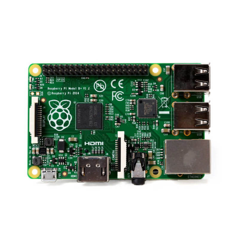
In this tutorial we show you five ways you can run a program on your Raspberry Pi at startup. We show you five ways to start a program at Raspberry Pi boot.
And if you don't already have a USB library, I know of several available but here's one: http://usb4java.org/
hushed nimbus
hardy plaza
Here's one of many web pages on how to start a script on startup on a Linux comp...
I already do this
Thanks for the library, I’ll look at that
mint leaf
hardy plaza
Well, I can't fault you for providing a lack of information but I don't really h...
End of the story:
There was no solution that would work for the raspberry Pi. In the end, I pulled the PWM control from the Pi and used an Arduino instead. I figured out a program that would allow setting the HZ based off the internal clock, and control two different PWM fans (at the same frequencies, different duty cycles) that way. There were other benefits, but I don’t want to waste your time going into unnecessary details.
Thank you for all of your help. The oscilloscope was the key. I appreciated your advise and thoughts on the matter. The project is now fully functional, and everything I’ve ever dreamed it would be.
hardy plaza
mint leaf
End of the story:
There was no solution that would work for the raspberry Pi. In...
Ahh, very good to hear you were able to get it going. I think a lot of the PWM solutions for the Pi are typically small boards that the Pi itself sends a signal to, that performs the PWM. E.g., a lot of the Pololu motor drivers, etc. Thanks for letting me know! 😄
honest maple
I got a CM4 8Gb! But tbh, I want a regular raspberry pi lol. Can anyone recommend a daughter board?
 novel vault
I've been trying to get my pigrrl zero working with my pi zero 2 w for a while, and was thinking it was mostly just couldn't get the 2.2 PiTFT screen working.
I eventually (just now) wrote the rasbian image, stuck the SD card in a Pi 2b ive got on hand, and followed the pitft instructions from adafruit.
Moved the SD over to the pi zero, and it's got a white line. Does anyone have a good idea for what could cause this? (Image in next message)

hmm, maybe this should be in 'help with projects'?
novel vault
yeah I'll head over to 'help with projects', at least to narrow down where the issue might be.
stray robin
hello! did someone interface raspberry with pdm mic?
wraith grove
sdram failure according to this
https://raspberrytips.com/green-and-red-light-on-raspberry-pi/
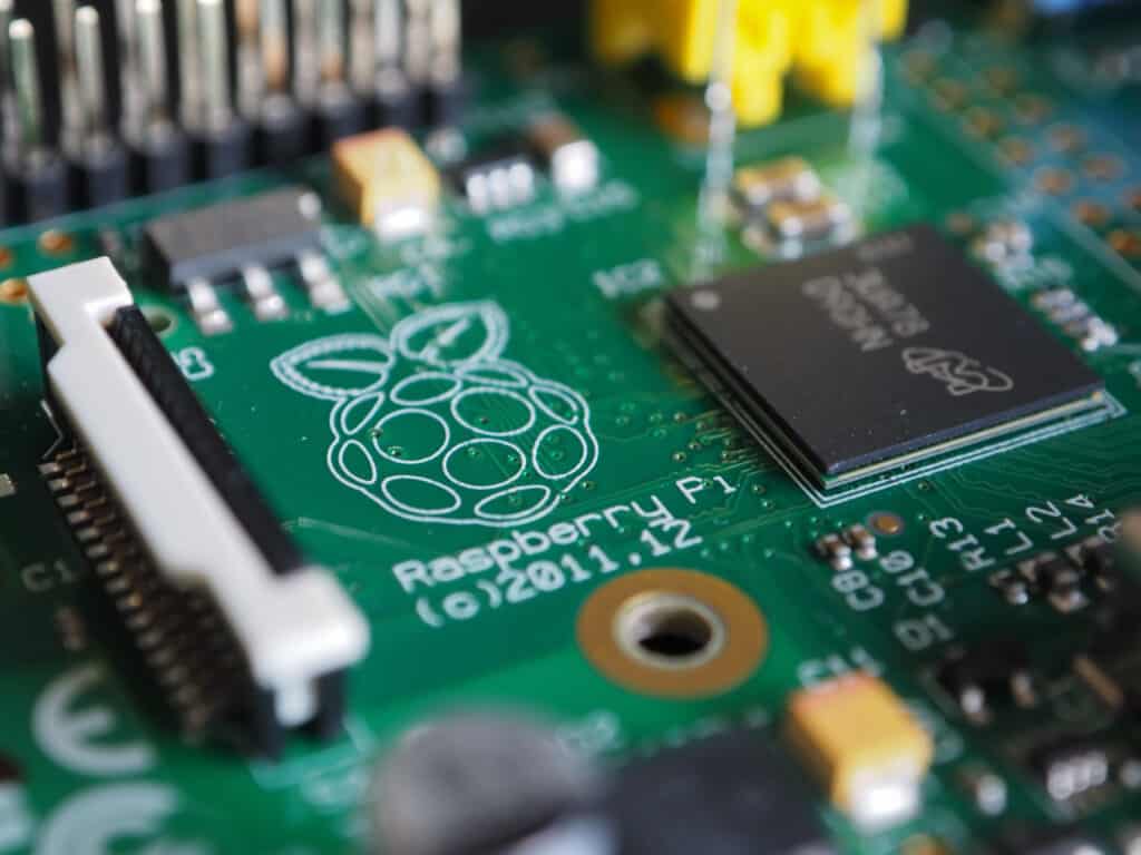
Understanding the different signals given off by technology can be confusing for both pros and beginners alike. Raspberry Pi, a miniature computer, is no exception…
 foggy onyx
wraith grove
sdram failure according to this
https://raspberrytips.com/green-and-red-light-on...
foggy onyx
wraith grove
sdram failure according to this
https://raspberrytips.com/green-and-red-light-on...
And green led doesn't blink at all
When sd card is incerted
And it shows nothing on screen in both cases
foggy onyx
wraith grove
sdram failure according to this
https://raspberrytips.com/green-and-red-light-on...
Any solution??
wraith grove
there have been anecdotes that adding hardware to the pi could make it work for a couple days
getting a new one is the clearest solution, and maybe seeing where your warranty stands
foggy onyx
wraith grove
there have been anecdotes that adding hardware to the pi could make it work for ...
Any thing i can do ???
wraith grove
if we've interpreted this correctly, something is wrong with the ram or the connection to the ram, etc, if you're a whiz at remanufacturing BGA chips, perhaps you could fix it?
foggy onyx


MUO
Raspberry Pi won't boot? New Raspberry Pi 4 not booting, with no red or green lights? Try these Raspberry Pi troubleshooting tips.
On inserting sd car it doesn't blink. So, i think i should try a last option
Reinstalling OS
woven cargo
Is this valid. I can't seem to get this to work.
While GPIO.input(15) == GPIO.LOW
'what are you trying to do?
steady rose
W should be w (case) and need a : at end of line
while GPIO.input(15) == GPIO.LOW:
    do_stuff()
but also not sure what exactly is happening, so would need more info on what is not working
foggy onyx
wraith grove
if we've interpreted this correctly, something is wrong with the ram or the conn...
But when i rebooted it
Rass don't show problem of 8 blinks
It just reported no sd card as normal
But when i started with sd card inserted
The ACT light doesn't light up
What should i do ????
Then i started with no sd card and i inserted sd card in between
I got this

Someone please help here
🙏
olive haven
It looks to me like your SD got corrupted. I would recommend reflashing the card, or a different one, using the Raspberry Pi Imager.
 olive pawn
Hi guys,
I am trying to get the serial data from an ultrasonic sensor (that is connected to my adafruit circut playground) to a raspberry pi. I am using the "Microsoft MakeCode for Circuit Playground Express" App on windows, and here is the code that I have

it shows the distance in the console log just fine, but i am having trouble with getting that serial data on a raspberry pi (or a computer). I have gotten a script from somewhere, but it doesnt seem to be working. Could someone help me with this?
here is the python code that i am trying to run:
#!/usr/bin/env python
import time
import serial
ser = serial.Serial(
port='/dev/ttyS0', #Replace ttyS0 with ttyAM0 for Pi1,Pi2,Pi0
baudrate = 9600,
parity=serial.PARITY_NONE,
stopbits=serial.STOPBITS_ONE,
bytesize=serial.EIGHTBITS,
timeout=1
)
counter=0
while 1:
ser.write("Write counter: %d \n"%(counter))
time.sleep(1)
counter += 1
umbral sable
olive pawn
here is the python code that i am trying to run:
#!/usr/bin/env python
import ti...
This Python code doesn't receive any serial data, it transmits a counter value out of the serial port.
olive pawn
umbral sable
This Python code doesn't receive any serial data, it transmits a counter value o...
im sorry, that is the completely wrong code
import serial
ser = serial.Serial('/dev/ttyS0', baudrate= 300) # open serial port
while True:
print(ser.read())
here's what i tried^
umbral sable
That should generally work if it's the correct port name. Are you getting any errors or any output?
olive pawn
yeah im getting an output of: h ' '
umbral sable
Do you mean b''? An "h" doesn't really make sense.
olive pawn
sorry i misread it becasuse of the resolution. I am getting an output of b''
umbral sable
Cool, that at least makes a little sense. The read() function returns a bytes type, so that's what Python is printing out... an empty string of that type (prefixed by "b" to indicate bytes).
However, it's a little unexpected that it would do that, since normally read() should block until it has some data to return.
olive pawn
umbral sable
However, it's a little unexpected that it would do that, since normally `read()`...
hmm yeah thats what i dont understand
stopbits=serial.STOPBITS_ONE, bytesize=serial.EIGHTBITS
perhaps i have to add this^^?
umbral sable
Those should be the defaults.
olive pawn
hmm
umbral sable
Is it just printing one b'' or continuously?
olive pawn
continuously
umbral sable
That sounds like the timeout value has a different default, so maybe pass timeout=None explicitly.
olive pawn
sure lemme try that
dry galleon
i've recently tried out NodeRed on my raspberry pi. Turns out it works better than expected and i want to keep using it as an NodeRed/Mosquitto server. Problem is, that the raspberry pi was used for Octoprint and i don't have a second one spare so now my 3D Printer has no raspberry pi anymore.
Is there a way i can run Octoprint, NodeRed and Mosquitto at the same time on the same pie? or do i have to buy a nother one?
olive pawn
umbral sable
That sounds like the timeout value has a different default, so maybe pass `timeo...
for some reason now it doesnt even show anything
no b''

@umbral sable do you know the best way to find the serial port for my adafruit?
cuz i got it from doing dmesg
mystic light
your serial port isn't receiving anything and since you set the timeout to None, it's just sitting there waiting.
olive pawn
mystic light
your serial port isn't receiving anything and since you set the timeout to None,...
do you perhaps know how to find the serial port from the raspberry pi?
 olive pawn
ok lemme try that
mystic light
somebody put out a bunch of serial port tools that have utilities to list out the CP serial ports
 mystic light

GitHub
CircuitPython board identification and information - GitHub - adafruit/Adafruit_Board_Toolkit: CircuitPython board identification and information
steady rose
it doesn't look like any serial devices entries are being created
olive pawn
olive pawn
this screenshot was before i plugged it in
steady rose
post screenshot after plugging in
steady rose
[ 3592.022189] usb 1-1.2: new full-speed USB device number 7 using xhci_hcd
[ 3592.160672] usb 1-1.2: New USB device found, idVendor=03eb, idProduct=2402, bcdDevice=42.02
[ 3592.160682] usb 1-1.2: New USB device strings: Mfr=1, Product=2, SerialNumber=3
[ 3592.160690] usb 1-1.2: Product: CPlay Express (app)
[ 3592.160697] usb 1-1.2: Manufacturer: CPlay Express (app)
[ 3592.160704] usb 1-1.2: SerialNumber: 1763391388
[ 3592.171639] hid-generic 0003:03EB:2402.0005: hiddev96,hidraw0: USB HID v1.00 Device [CPlay Express (app) CPlay Express (app)] on usb-0000:01:00.0-1.2/input1
still no serial devices entry being created
olive pawn
huh that is weird
and i have the serial turned on by doing raspi-config>Interface options>serial port>enable
steady rose
the issue is with whatever is running on the circuit playground
it's not generating a serial port connection with the pi over USB
olive pawn
hmm
this is the code that i am running on the circut playground

i found it the easiest to do with block codes :/
(cuz i do have a circuit playground bluefruit but didn't want to code it in circuit python, thinking it'd be harder)
mystic light
you'll probably get more help if you're using circuitpython to program your board, since that's what people are familiar with
steady rose
yah, sorry, i also don't know much about the serial block in makecode
it may be specific for use with the associated app
olive pawn
steady rose
it may be specific for use with the associated app
ok ill try this
can you tell me what specifically im looking for when I do dmesg -w?
steady rose
it can vary, but typically a message indicating a device with tty in the name
[1301527.849206] cdc_acm 2-1.5:1.0: ttyACM1: USB ACM device
ok thank you
steady rose
^^ try that
written in arduino. prints "Hello world!" every 500ms.
but can use to test behavior on the pi with known working serial code running on the CPX
olive pawn
 olive pawn
ohh ok
so i put the file into CPLAYBOOT
and connect the adafruit to my raspi
i dont think im still getting the signal
 steady rose
i get this:
[  258.484788] usb 1-1.1.2: new full-speed USB device number 5 using dwc_otg
[  258.627227] usb 1-1.1.2: New USB device found, idVendor=239a, idProduct=8018, bcdDevice= 1.00
[  258.627250] usb 1-1.1.2: New USB device strings: Mfr=1, Product=2, SerialNumber=3
[  258.627267] usb 1-1.1.2: Product: Circuit Playground Express
[  258.627282] usb 1-1.1.2: Manufacturer: Adafruit
[  258.627297] usb 1-1.1.2: SerialNumber: 85C4C413504C5435382E314AFF02132C
[  258.708548] cdc_acm 1-1.1.2:1.0: ttyACM0: USB ACM device
[  258.710843] usbcore: registered new interface driver cdc_acm
[  258.710859] cdc_acm: USB Abstract Control Model driver for USB modems and ISDN adapters
/dev/ttyACM0 would be the serial entry in that case
pi@raspberrypi:~ $ cat /dev/ttyACM0
Hello world!

Hello world!

Hello world!

Hello world!

Hello world!
^^ try that one. it adds neopixel animation so you'll at least know the code is running on the CPX.
olive pawn
what i am doing is downloading this file and copy and pasting it onto the CPX. The green led is animating, and i plug it into my raspberry pi (through the usb port)

still i only get this
steady rose
are you copying the UF2 to a folder with BOOT in the name?
 steady rose
how do you upload UF2's downloaded from makecode?
olive pawn
just press the download button and it automatically puts it
or i download the UF2 file and drag it to CPXPLAYBOOT
 olive pawn
yeah that drive
steady rose
it has BOOT in the name
olive pawn
i thought it was folder ohh
steady rose
drag the UF2 to that folder
olive pawn
yeah that ejects my cpx
and then plays the animation
then i take it out of my computer
and put it into the raspberry pi
steady rose
if the neopixel animation is playing, then the code has uploaded successfully and is running
olive pawn
yeah
steady rose
does the animation play again when plugged into the pi?
 steady rose
do you see a message like this:
[ 3310.994861] cdc_acm 1-1.3:1.0: ttyACM0: USB ACM device
in dmesg output?
 olive pawn
4 b
steady rose
what os are you running?
olive pawn
rasbian

i even put it in a google doc and searched for tty

the only ttyAMA0 that shows up is this one
steady rose
those are other things
not sure why it's not working
just tried a pi 4 here
and it works fine
[   62.464641] usb 1-1.1: New USB device found, idVendor=239a, idProduct=8018, bcdDevice= 1.00
[   62.464664] usb 1-1.1: New USB device strings: Mfr=1, Product=2, SerialNumber=3
[   62.464682] usb 1-1.1: Product: Circuit Playground Express
[   62.464699] usb 1-1.1: Manufacturer: Adafruit
[   62.464716] usb 1-1.1: SerialNumber: 85C4C413504C5435382E314AFF02132C
[   64.232937] cdc_acm 1-1.1:1.0: ttyACM0: USB ACM device
[   64.236127] usbcore: registered new interface driver cdc_acm
[   64.236145] cdc_acm: USB Abstract Control Model driver for USB modems and ISDN adapters
pi@raspberrypi:~ $ uname -a
Linux raspberrypi 5.10.103-v7l+ #1530 SMP Tue Mar 8 13:05:01 GMT 2022 armv7l GNU/Linux
[ 2.306125] usb 1-1.2: New USB device strings: Mfr=1, Product=2, SerialNumber=3
[ 2.306145] usb 1-1.2: Product: Circuit Playground Express
[ 2.306162] usb 1-1.2: Manufacturer: Adafruit
[ 2.306179] usb 1-1.2: SerialNumber: E91B379C504B3233382E3120FF0F042B
yeah this is all i get
nothing after the serial number
let me try another usb cable
steady rose
and other USB ports on the pi
olive pawn
[ 31.832647] cam-dummy-reg: disabling
[ 227.890052] usb 1-1.2: USB disconnect, device number 3
[ 235.816817] usb 1-1.2: new full-speed USB device number 4 using xhci_hcd
[ 235.965978] usb 1-1.2: New USB device found, idVendor=239a, idProduct=8018, bcdDevice= 1.00
[ 235.966009] usb 1-1.2: New USB device strings: Mfr=1, Product=2, SerialNumber=3
[ 235.966030] usb 1-1.2: Product: Circuit Playground Express
[ 235.966048] usb 1-1.2: Manufacturer: Adafruit
[ 235.966066] usb 1-1.2: SerialNumber: E91B379C504B3233382E3120FF0F042B
[ 235.974061] cdc_acm 1-1.2:1.0: ttyACM0: USB ACM device
WAIT
I THINK ITS THAT ONE
[ 235.974061] cdc_acm 1-1.2:1.0: ttyACM0: USB ACM device

and its printing hello world!
steady rose
cool. yep. that's it.
steady rose
wow. really weird. the cable worked well enough to show the initial connection.
olive pawn
steady rose
wow. really weird. the cable worked well enough to show the initial connection.
ikr
thats super weird
steady rose
usb cable issues are a thing, unfortunately
foggy onyx
Was installing emacs but now its suddenly got stucked :(


What should i do now ???
Key board and mouse are not working
Every thing is stucked
foggy onyx
Then i removed power supply and rebooted it
Then i got

Then i use second sd card (flashed yesterday)
And i got

Why my sd cards are working for sometime and getting corrupted ????
Some please help me
I was just seeting up my sd card
It was stucked from many hours
So, i did it
foggy onyx
Struggling from last night before of problems
Got something related https://forums.raspberrypi.com/viewtopic.php?t=300269
 zinc jackal
I'm just waiting for a micro USB to USB-A hub to arrive, so I can use my Pi Zero 2 W. 😎
faint sparrow
Could anyone help me with ST25DV16K NFC tag? in the beginning it all works fine as I tried to write information like url and text with an NFC app on my iphone, but then at some point the NFC stops working and the app says the tag is not supported, So I guess i made it corrupted somehow, is there anyway to fix it?
 slender meadow
Hi All, would this be the correct place to ask about a project i am stuck with using a PI to count pulses from a hall effect sensor on a water meter?
Hi Ed lol
steady rose
slender meadow
Hi All, would this be the correct place to ask about a project i am stuck with u...
yep. go ahead and just ask.
slender meadow
thanks
I have a pulse generator, generating 270Hz at 50% Duty Cycle. It reads correctly on a third pard "built" counter, but for the life of me I cannot get a pulse count anywhere close on the PI. I have Ubuntu running on the PI and dont know whether to use C or Python3 for the project? I have a small DSO and can measure the waveform, getting a perfect square wave at 269Hz.
I have googled and asked on forums and keep getting told to use this library or this is something similar. I cant believe there is nothing clear cut out there, am I asking it wrong? lol. I can show the latest iteration of my python test code?
 kindred tangle
I just posted a huge message and it was instantly deleted lol.
Does anyone know how to get in contact with Tony DiCola about his RGB Matrix Mirroring software? It's been incompatable with the Pi4 for over a year now, and its a very useful piece of software that's allowed me to make really cool RGB clocks.
steady rose
looks like the bot flagged it for a banned word
kindred tangle
It might have been because i posted an external link or something.
Oh ok.
I used his software to make this https://www.youtube.com/watch?v=pCmGmLDWalE


Adafruit Learning System
Show the Pi's video output on a large RGB LED matrix display!
This was his software 😄
 lost wolf
kindred tangle
Does anyone know how to get in contact with Tony DiCola about his RGB Matrix Mir...
lost wolf
kindred tangle
Does anyone know how to get in contact with Tony DiCola about his RGB Matrix Mir...
Tony doesn't work with Adafruit anymore. Contacting him about this wouldn't be appropriate. This is way outside my wheelhouse, so I'm of no help to assist in porting it to RPi4.
kindred tangle
Ah thats probably why he never answered any of my emails lol.
lost wolf
That would do it, yeah. 🙂
kindred tangle
Maybe someone should eventually look into porting it, because its very useful for dumb dums like me with the software side of things.
Might help the sales of the HAT+RTC/Bonnet too 😛
lost wolf
Other than Pis being unobtanium.
kindred tangle
Im going to start using that word more often rofl! Ive been scouring ebay for 3B/3B+ models for the time being.
lost wolf
Oof yeah.
kindred tangle
Big oof indeed.
@lost wolf Anyhoo, thanks for the response! And i hope some gifted programmer eventually updates it.
lost wolf
kindred tangle
<@!330227457296957440> Anyhoo, thanks for the response! And i hope some gifted p...
You're welcome! Hopefully that happens eventually. If you manage to do it, let us know 🙂
kindred tangle
Rgr!
 frail rapids
We keep getting this error message, as far as we know everything is wired correctly. Any ideas? We’ve tried swapping out our Raspberry Pi and BMP3 sensor, we’re using a Raspberry Pi 3b+.

 civic rune
Have you tried an I2C scan?
frail rapids
civic rune
Have you tried an I2C scan?
What do you mean? I2C detect?
civic rune
Check these out https://docs.circuitpython.org/en/latest/shared-bindings/busio/#busio.I2C and https://learn.adafruit.com/circuitpython-basics-i2c-and-spi/i2c-devices. CTRL+F for 'scan'
hardy plaza
frail rapids
We keep getting this error message, as far as we know everything is wired correc...
If you see no devices on i2cdetect it's not a software problem, it's a hardware problem.
steady rose
^^ seconding that. check wiring.
hardy plaza
Missing power or ground, SDA and SCL swapped, pins shorted somewhere. The i2cdetect is scanning the I2C bus and clearly there is no working device, otherwise it would show up. Perhaps try adding another I2C device to the bus to see if it shows up. That would at least tell you if it's the device you're using or the bus itself.
The other thing that sometimes causes this is if the wires connecting the I2C device are too long. Under about a foot is usually okay, after that you're in the realm of gambling.
zinc jackal
lost wolf
Other than Pis being unobtanium.
I was waiting months just to order a Pi Zero 2 W.... Finally got one. 😄
 dusty swallow
jo
does german support exist?
i have a problem with adafruit_hid i want to change keyboard layout do german but it dosnt work
 rain fulcrum
Really strange Wi-Fi 5g connection issue with a brand new Pi400. Is this a known issue with Bullseye 32bit and 64bit? I haven't tried another OS or the Raspberry Pi OS (Legacy) version yet.
° Fresh install of bullseye 32bit or 64bit
° I went through the initial setup.
° Wi-Fi Country set to US.
° Selected my 5g wireless AP.
° Downloaded the updates supplied.
° Rebooted the 400 and my 5g access point will not connect. Nowhere to be found on the dropdown list. Other 5g access points (not mine) show in the dropdown.
Has this happened to anyone else?
foggy onyx
i am using this plugin https://github.com/romkatv/powerlevel10k#oh-my-zsh

GitHub
A Zsh theme. Contribute to romkatv/powerlevel10k development by creating an account on GitHub.
i install as they said
but p10k command is not workinh
got something related https://stackoverflow.com/questions/16808231/how-do-i-set-default-terminal-to-terminator but where is change Settings Manager located on rpi ???

Stack Overflow
I'd like to have Terminator replace the default terminal. For instance, when right-clicking inside a folder then selecting "open terminal", I'd like Terminator to open instead of the defa...
olive pawn
hey @steady rose