#help-with-linux-sbcs
1 messages · Page 25 of 1
 civic rune
I'm thinking it didn't stick because in the setup menu, it insisted that the default name/pw were in effect and I must change them.
 olive haven
You mean the setup stuff in the GUI?
civic rune
yup
also in the GUI when I went to change the password, it didn't challenge me to provide a password.
olive haven
I don't have a display on this PI. Once I figured out how to enable VNC, I VNC'd in and started through that dialog. As soon as it told me I still had the default password, I exited out of the setup. Logged in again via ssh and still had the pw I had set.
olive haven
VNC Viewer by RealVNC Ltd. (I'm on a Mac), it was a free download (some time ago)
civic rune
mk, I'm just considering developing on the pi over SSH and wondering if VNC would be better
olive haven
I've mostly done Pi stuff via SSH; I'm pretty used to command line Linuxy stuff.
I only started using the desktop version of Pi OS a year or so ago when I wanted to have a small touchscreen on the Pi for a project.
civic rune
I've just got to work something out with the IT fella, ports are blocked all over the place
olive haven
You mean there's a firewall between you and the Pi?
civic rune
seems to be?
I can access the network on the pi, and on my PC, but the two cannot speak
olive haven
So how are you even getting to the Pi? Display & keyboard?
olive haven
I'm so tempted to say "how quaint" -- please forgive me
civic rune
it's OK
It's easier for me to develop python this way
And to see the file system.
But I get that it's not particularly l33t
olive haven
well, it's partly I don't have a convenient monitor & keyboard to use with the Pi's.
Once I learned about setting them up for ssh and wifi -- which the new Imager makes SO much easier -- I just went with that
civic rune
we're like the Gifts of the Magi: I have a convenient M&K setup but no usable network. You have inverse
Actually that's not gifts of the magi
I forget what it is
olive haven
I saw you talking about editors somewhere; what'd you end up using
civic rune
I'm just going with Geany, it's what shipped and it's...fine?
olive haven
haven't used it. Mostly when I need to edit files on the pi, I use nano, and it's ... ok?
But it works over SSH in a terminal window as well
civic rune
yeah you can't use Geany in the CMD line
olive haven
would you be comfortable with ssh/sftp if you could talk the IT guy into opening up the requisite ports? Or VNC (I don't actually know what port(s) that needs)
civic rune
I'm comfortable getting comfortable
olive haven
not sure I follow
civic rune
I'm comfortable starting the process of learning what I need to learn
olive haven
ah
Well, one of the advantages of being able to work from your PC would be a wider choice of development environments.
Plus the kind of easy backup that entails.
But if you're getting along ok on the Pi, don't let better be the enemy of good
civic rune
I think I'll look at my deadline for my next project, after this project is done, and see what I think I have time for in terms of learning curves
olive haven
https://vncviewerapp.com -- just found the link, for future reference
In raspi-config there was a place to set up the resolution of a VNC GUI, and another place to enable VNC connections -- no other software needed on the PI
civic rune
thx!
Having a weird pygame issue. No sound is coming from the speakers connected to my pi. I've also tried playing the .mp3 with the built in mp3 player on the pi, and no dice. The .mp3 plays on my PC just fine
 west sierra
civic rune
Having a weird `pygame` issue. No sound is coming from the speakers connected to...
west sierra
civic rune
Having a weird `pygame` issue. No sound is coming from the speakers connected to...
How large is the MP3, and what's the bitrate?
civic rune
Let me check. I should note that pygame worked fine to play this exact MP3 on another device
west sierra
Ah, weird. Maybe it's missing a decoder?
civic rune
6.8 MiB
west sierra
that's a chonky mp3
civic rune
Not sure about bitrate, idk how to tell that
west sierra
you even have a sound card on that Pi that can output that? ahhaha
civic rune
I think so?
west sierra
let's find out the bitrate, one sec
west sierra
sudo apt install -y mediainfo
then you can run mediainfo on that mp3 to find out the deets
civic rune
unable to install some stuff
Let's see if it works
$ mediainfo fails to bring anything up
west sierra
nothing, no errors, no ... just new command line prompt?
civic rune
command not found
I got a bunch of errors when installing that it was failing to install stuff
west sierra
that's a COMPLETELY different result than "fails to bring anything up"
civic rune
you're right, it's near end of shift, I ahve a sleepy
west sierra
lol
it's just like... all kinds of engineers just forget to troubleshoot when they are the "customer." It's like... did you even power it on and off?
so, wait, what are you running on the Pi, which OS?
west sierra
$ sudo apt install mediainfo
Reading package lists... Done
Building dependency tree... Done
Reading state information... Done
The following additional packages will be installed:
libmediainfo0v5 libmms0 libtinyxml2-8 libzen0v5
Suggested packages:
mediainfo-gui
The following NEW packages will be installed:
libmediainfo0v5 libmms0 libtinyxml2-8 libzen0v5 mediainfo
0 upgraded, 5 newly installed, 0 to remove and 0 not upgraded.
Need to get 2,148 kB of archives.
After this operation, 7,532 kB of additional disk space will be used.
Do you want to continue? [Y/n] y
Get:1 http://deb.debian.org/debian bullseye/main arm64 libmms0 arm64 0.6.4-3 [32.1 kB]
Get:2 http://deb.debian.org/debian bullseye/main arm64 libtinyxml2-8 arm64 8.0.0+dfsg-2 [28.8 kB]
Get:3 http://deb.debian.org/debian bullseye/main arm64 libzen0v5 arm64 0.4.38-1 [94.9 kB]
Get:4 http://deb.debian.org/debian bullseye/main arm64 libmediainfo0v5 arm64 20.09+dfsg-2 [1,912 kB]
Get:5 http://deb.debian.org/debian bullseye/main arm64 mediainfo arm64 20.09-1 [80.2 kB]
Fetched 2,148 kB in 0s (6,282 kB/s)
Selecting previously unselected package libmms0:arm64.
(Reading database ... 35620 files and directories currently installed.)
Preparing to unpack .../libmms0_0.6.4-3_arm64.deb ...
Unpacking libmms0:arm64 (0.6.4-3) ...
Selecting previously unselected package libtinyxml2-8:arm64.
Preparing to unpack .../libtinyxml2-8_8.0.0+dfsg-2_arm64.deb ...
Unpacking libtinyxml2-8:arm64 (8.0.0+dfsg-2) ...
Selecting previously unselected package libzen0v5:arm64.
Preparing to unpack .../libzen0v5_0.4.38-1_arm64.deb ...
Unpacking libzen0v5:arm64 (0.4.38-1) ...
Selecting previously unselected package libmediainfo0v5:arm64.
Preparing to unpack .../libmediainfo0v5_20.09+dfsg-2_arm64.deb ...
Unpacking libmediainfo0v5:arm64 (20.09+dfsg-2) ...
Selecting previously unselected package mediainfo.
Preparing to unpack .../mediainfo_20.09-1_arm64.deb ...
Unpacking mediainfo (20.09-1) ...
Setting up libmms0:arm64 (0.6.4-3) ...
Setting up libtinyxml2-8:arm64 (8.0.0+dfsg-2) ...
Setting up libzen0v5:arm64 (0.4.38-1) ...
Setting up libmediainfo0v5:arm64 (20.09+dfsg-2) ...
Setting up mediainfo (20.09-1) ...
Processing triggers for man-db (2.9.4-2) ...
Processing triggers for libc-bin (2.31-13+rpt2+rpi1+deb11u2) ...
just ran that on a Pi CM4
civic rune
so
west sierra
what did it do?
west sierra
Just imagine me right now... smacking you in the head with a giant foam hammer while you are doing this
civic rune
lol
civic rune
well I now have mediainfo but VLC gave me the data
west sierra
cool, what was the bitrate?
civic rune
192 kb/s
civic rune
just your normal stereo speakers/amp
west sierra
You got some hifi speakers with a tube amp or something?
civic rune
I didn't set this up, this is inherited stuff
west sierra
but, you said pygame
west sierra
what is it outputting?
civic rune
bunch of sounds
Music
other stuff
music needs to be clear but nothing really crazy hi fidelity
west sierra
OK. I am going to go out on a limb here, that you could probably go down to at least 128 Kbps
possibly lower
I would test it
civic rune
let me figure out how to do that
there are a bunch of dodgy sites for it
ack! gotta clock out, I'll have to tackle this tomorrow
west sierra
ffmpeg -i input.mp3 -codec:a libmp3lame -b:a 128k output.mp3
something like that
perhaps
then you can tweak down to 128k and 96k and play it and see if there's any difference...
I am not a hifi guy, and the only thing I really notice going below 128k is bass will be weaker... but, then again... I don't know your exact use case, but can guess.
civic rune
The better sounding the better but amazing quality sound that won't play is useless
west sierra
just go full flac, highest bitrate possibly
buy some $50,000 speakers and a $100,000 amp
depending on the environment... a perfectly balanced room that's been acoustically calibrated will sound amazing, but a cafe or a large place where there's ambient noise... almost nobody's going to hear the difference, and those that do, will not care.
talking voices can often be downsampled quite a bit compared to something like a song by Jinjer for instance 😄
 faint sparrow
In the bash man page, the idea of Job Control is discussed.

My fingers do it so fast I don't remember doing it, but I'm fairly sure a fg <$pid> brings a background task back to the foreground.
iirc Control Z was often bound to tty-based programs (ncurses probably as well) as a way to .. I don't know .. suspend them I think it was called.
Same mechanism probably works when you append a '&' to a command line.
It's pretty rare for me to want to bring one of those back to the foreground; my techniques have changed more towards sending signals instead (inter-process communications iirc).
$ kill -SIGHUP <$pid> maybe .. been a while since I've thought about it.
$ man 7 signal
$ man 7 svipc is a proper reference, I think, to inter-process communications (I don't know if signals are related or not)
olive haven
@civic rune Just to expand on what @faint sparrow pointed out, if you (inadvertently or no) put a process in the background by hitting ctl-Z, you can foreground it again with a simple fg command. If you have several processes in the background, you can get a list of them with the jobs command. Each one will have a number in front of it, and you can bring back say number 1 with fg %1; a simple fg will foreground the most recently backgrounded one (which will have a + after the number).
civic rune
Cool! Thanks folks!
 shadow prism
Can someone here help me with enabling SSH over USB with the Raspberry Pi Zero on Windows? I followed the normal instructions (add dtoverlay=dwc2 in config.txt, modules_load=dwc2,g_ether in cmdline.txt, touching SSH), yet I cannot SSH over raspberrypi.local. Interestingly, Windows detected it as a RNDIS/Ethernet device before concluding that the Zero was a USB Serial one...
civic rune
Anyone have pygame experience? I'm reading the API docs for pygame.mixer.music and am not finding an easy way to do what I want. I'm trying to profile some code that does stuff while a pygame song plays and also does stuff after the music ends. I'm trying to record when the song ends. I think set_end_event() is what I want but I'm unclear about how the event queue works
 deep pawn
using a pi to connect to an adc to a thermistor. googled a lot and read about wheaton bridges. so i am trying to follow this circuit diagram in the attached picture. this is my first time using a breadboard or doing any circuitry/electronics stuff. before i turn on the pi, is this safe or will i blow up one of the devices? thanks for any tips /advice


 rotund pivot
Maybe it's old and I never noticed it? Raspberry Pi Imager can set up wifi and ssh automagically. Very handy.
civic rune
rotund pivot
Maybe it's old and I never noticed it? Raspberry Pi Imager can set up wifi and s...
It's relatively new. I swear it doesn't work right for me though. Every time I set up a pi, I boot the pi and the GUI still tells me that the default username/PW are present.
rotund pivot
I just did Lite, so ssh keys let me in.
Is this really necessary?After this operation, 1,599 kB of additional disk space will be used. Do you want to continue? [Y/n] Y
KILOBYTES
lol that used to be a lot
olive haven
civic rune
It's relatively new. I swear it doesn't work right for me though. Every time I s...
That's a bug, I'm pretty sure. That setup routine doesn't seem to know that you've already set things up in the imager. I would just ignore that (hit the X in the corner).
civic rune
rotund pivot
lol that used to be a lot
It's cute when it gives me warnings like that
civic rune
olive haven
That's a bug, I'm pretty sure. That setup routine doesn't seem to know that you'...
I submitted a bug report, we'll see what happens next
civic rune
So when I run my script, which uses RPi.GPIO, I get warnings when I do
GPIO.setup(pinNumber, GPIO.OUT)
that the channel is already in use. I think I can stop this by running GPIO.cleanup(), but I'm looking for a way to tell if the warning is going to be given before I call GPIO.setup(), so I know to call cleanup(). Thoughts?
 steady rose
see what it says about the warning here:
https://sourceforge.net/p/raspberry-gpio-python/wiki/BasicUsage/
if RPi.GPIO detects that a pin has been configured to something other than the default (input), you get a warning
so if gpio_function returns something other than GPIO.IN, that seems to be the same as triggering the warning
(can also turn off warnings)
civic rune
I considered turning off the warnings, but I don't like doing that unless I have a really deep understanding of the consequences
hmm another weird issue: when using pygame, when I check the type of pygame.mixer.music.get_pos() with:
>>> type(pygame.mixer.music.get_pos())
I get
<class 'int'>
but when I use testing code like
time = pygame.mixer.music.get_pos()
if not isinstance(time, int):
  print("NOT AN INT")
I always get
"NOT AN INT"
as output
Nevermind, I see what I did, it was silly
civic rune
hmmm I've found a bug but I don't know who to report it to: Adafruit or Raspberry Pi. When I plug in my AW9523 breakout using the female header -> stemma QT cable, my pi shuts down and/or stops working properly. I can get the pi to work properly if I pull power and re-plug it with the stemma QT cable already plugged in. Who does it seem I should bring this up to?
 lost wolf
Wait... in what order? You shouldn't be plugging stuff in when it's powered on, it can short or cause issues even if you're careful. If I'm reading what you said properly, then that isn't necessarily unexpected.
lost wolf
I2C isn't hot swappable, even though STEMMA QT really makes you want to do it.
 turbid rivet
Certain I2C sensors may be okay if you ensure ground is connected before power, but the physical StemmaQT connector is absolutely not capable of this...
turbid rivet
If the Pi is shutting down as a result of connecting power, you're probably getting an inrush strong enough to cause a brownout condition. I imagine your AW9523 is already loaded upon connection, so you should absolutely only connect/disconnect while power is off.
civic rune
It's not loaded but the inrush could be enough I guess
 tired marsh
Adafruit even has a product for that: https://www.adafruit.com/product/5159

As we've been adding STEMMA QT connectors to our breakouts and dev boards, folks have been really enjoying the simplicity and speed of plugging in I2C sensors and devices for quick ...
though it only mentions a stuck bus recovery
civic rune
I don't need to do hot swapping, I can just power down. Thx tho
civic rune
the pins 0 and 1 can be used for I2C on the pi right? I think I see that they are usually used for EEPROM on a hat, but if I'm not using an official hat and I want to use the default I2C pins for something else... there's nothing really preventing me from using 0 and 1 for I2C, correct?
I'd need to do something like:
import board
import busio

i2c = busio.I2C(board.D1, board.D0)
?
ah that didn't work
turbid rivet
Pi 4? There should be like 6 I2C peripherals available. IIRC, you do need external pullups on anything outside of i2c-1.
steady rose
does the need for using the standard i2c pins for something else out way the mild complexity you'll add by using non-default i2c?
civic rune
One of the default pins for I2C has an alternate function that wakes the pi from a halt state when you pull it low. I'd like to have that functionality available. It's not mission critical but I would like it
steady rose
there's a software i2c overlay you can use. i think on any gpio.
civic rune
I can always pull power and re-plug but that's inelegant
steady rose
and use with this lib:
https://github.com/adafruit/Adafruit_Python_Extended_Bus
civic rune
It seems like it's equal complexity to use either the alt hardware I2C or software overlay. What are the downsides of using the alt-hardware?
turbid rivet
I believe you can use it for your app if you're not using the Pi camera or Pi display, and avoid the HAT EEPROM address. However, you will still need external pullups for i2c-0 or any software i2c overlay.
steady rose
^^ yep
civic rune
civic rune
I'd need to do something like:
```py
import board
import busio
i2c = busio.I2C(...
Ok thanks! Any idea why I got this error with this code:
ValueError: No Hardware I2C on (scl,sda)=(1,0)
Valid I2C ports: ((1, 3, 2), (0, 1, 0))
I am not using a display or camera so no issues there
steady rose
only specific pins can be used. it's a manual mapping inside blinka.
turbid rivet
Does it need to be enabled in boot/config.txt?
steady rose
civic rune
I will if I just can't get this to work but I'm confused as to how I can pass in port 0 to the busio function since it doesn't take that as an argument
but seems to require that information
steady rose
you can't pass in port number with busio. it determines it based on the pins passed in.
civic rune
but it isn't working for some reason
steady rose
what isn't working?
civic rune
I run
i2c = busio.I2C(board.D1, board.D0)
and get
ValueError: No Hardware i2c on (scl, sda) = (1,0)
Valid I2C ports: ((1, 3, 2), (0, 1, 0))
oh man, if it turns out that I just forgot that this is fresh install again...
/dev/i2c-2/
I enabled it and now I have:
/dev/i2c-1 /dev/i2c-2
steady rose
i gave wrong link above. for pi 4, it's this table:
https://github.com/adafruit/Adafruit_Blinka/blob/4a33dc0ce6eee7103888bbbfde46617d7d3b59c8/src/adafruit_blinka/microcontroller/bcm2711/pin.py#L95
civic rune
I'm on pi 3
steady rose
and without the /dev entries, the open was failing and landing in this exception:
https://github.com/adafruit/Adafruit_Blinka/blob/4a33dc0ce6eee7103888bbbfde46617d7d3b59c8/src/busio.py#L121
 civic rune
ooh for/else I hadn't seen before
steady rose
wondering how it got this output...
Valid I2C ports: ((1, 3, 2), (0, 1, 0))
 umbral sable
steady rose
wondering how it got this output...
```
Valid I2C ports: ((1, 3, 2), (0, 1, 0))
...
umbral sable
steady rose
wondering how it got this output...
```
Valid I2C ports: ((1, 3, 2), (0, 1, 0))
...
Hmmm? That's just a dump of the i2cPorts tuple variable.
steady rose
yep. so not hitting exception.
but that list is for the BCM2711
oh...nvm.
was think it was dumping lower down
for BCM283x
so why didn't this work?
i2c = busio.I2C(board.D1, board.D0)
civic rune
I'm much confuse
steady rose
oh. it probably did hit the exception when it tried to open.
but it just passes
so finally exhausts the iterator
you'll need to have /dev/i2c-0
civic rune
Seems like a good case for a PR to add more checking
I'll see if I can understand enough to do that
https://forums.raspberrypi.com/viewtopic.php?t=167773
Hmmm, maybe the I2C0 can't be used at all
I guess I'll have to use software I2C
steady rose
your only options via blinka/busio on the pi3 (or any BCM283x pi) are:
/dev/i2c-1 on SCL/SDA (D3/D2)
/dev/i2c-0 on D1/D0
civic rune
oh I can't do software i2c?
steady rose
sure. then you'd use the extended bus library.
steady rose
like that
seems ok i guess. those pins have always been "reserved for HATs. do not use"
civic rune
so does extended bus work with any GPIO? It seems not
steady rose
i think so? i'd avoid ones like the SPI bus if possible.
civic rune
the docs aren't super clear on that
ones ec
https://circuitpython.readthedocs.io/projects/extended_bus/en/latest/api.html
Implies that it only works with existing buses
 civic rune
hahh ok
*ahh
let me pull up my board and find some convenient GPIO
thx for your help!
steady rose
looking for good ref. always have trouble finding it.
civic rune
I've looked into it before
steady rose
it's simple. once found.
civic rune
how could I figure out what /dev/i2c-2 is hooked up to?
steady rose
dtoverlay=i2c-gpio + stuff to define pins and bus num
Name:   i2c-gpio
Info:   Adds support for software i2c controller on gpio pins
Load:   dtoverlay=i2c-gpio,<param>=<val>
Params: i2c_gpio_sda            GPIO used for I2C data (default "23")

        i2c_gpio_scl            GPIO used for I2C clock (default "24")

        i2c_gpio_delay_us       Clock delay in microseconds
                                (default "2" = ~100kHz)

        bus                     Set to a unique, non-zero value if wanting
                                multiple i2c-gpio busses. If set, will be used
                                as the preferred bus number (/dev/i2c-<n>). If
                                not set, the default value is 0, but the bus
                                number will be dynamically assigned - probably
                                3.
dtoverlay=i2c-gpio,i2c_gpio_sda=23,i2c_gpio_scl=24,bus=4
something like that
civic rune
steady rose
in README here:
<https://github.com/raspberrypi/firmware/tree/master/boot/overla...
e.g. to use GPIO 9 and 11 as SDA and SCL it would be:
dtoverlay=i2c-gpio,bus=3,i2c_gpio_sda=9,i2c_gpio_scl=11
right?
steady rose
try it. those are spi pins. so may conflict if spi is enabled.
civic rune
ahh let me re-configure then
I am going to try pins 4 and 17
@steady rose It's working great, thanks!
 woven cargo
I was wondering if someone would be able to help me install circuit python onto a raspberry pi zero
 half fractal
Greetings! I am trying to send mnemonic code (characters) from a raspi to a USB device. I am trying to do this with /dev/ttyUSB0 and /dev/ttyAMC0 Would anyone mind pointing me in the right direction?
tired marsh
half fractal
Greetings! I am trying to send mnemonic code (characters) from a raspi to a USB ...
you can use pyserial https://pyserial.readthedocs.io/en/latest/
half fractal
tired marsh
you can use pyserial <https://pyserial.readthedocs.io/en/latest/>
mind if I bug you about this after I get stuck>
tired marsh
you can ask here, there are people who can help
half fractal
thank you
tired marsh
most programming environment would have the ability to send data to a serial port, it's usually as simple as writing to a file
I'm curious, do you have a link to the product you are using ?
half fractal
I'm brand new to raspi as I've been using circuitpython boards for projects previously, now I need the device to show up as a USB host.
I don't have a link to it, I can't find the device for sale, I had to look up the datasheets on all the IC the board uses just to figure out what it does
civic rune
half fractal
I'm brand new to raspi as I've been using circuitpython boards for projects prev...
just a heads up, it's confusing to be sure but: Cpython generally refers to desktop or "normal" python. We tend to say Cirpy or Circuitpython or even just CP around here.
woven cargo
Has anyone ran into this issue with PWMOut is not defined?
 umbral sable
Looks like it's probably failing to import the pwmio library from Blinka:try: from typing import Union, Optional from pwmio import PWMOut from digitalio import DigitalInOut except ImportError: pass
tired marsh
yeah, but blinka is installed or it would error on import micropython
I'm not entirely sure how to use Blinka in Mu on a Pi, I assume it uses the system's python ? in doubt, try updating blinka from a terminal
sudo pip install -U adafruit-blinka
Ok. I'll give it a try.
Still no luck.
tired marsh
you could check that you don't have a local file or directory named typing or pwmio, which would cause python to load the wrong one, other than that I don't know what could be going wrong
 brave sparrow
I'm planning a project with the eink bonnet (https://www.adafruit.com/product/4687) on a Pi 2 B. The I2C port is spoken for, and I'm looking for other GPIO options. The inside terminals of the buttons map to pins 29 and 31, can I just solder to those pads to use those pins for externally-powered sensor input?


Easy e-paper finally comes to Raspberry Pi, with this bonnet that's designed to make it a breeze to add a 2.13" 250x122 crisp monochromic eInk display. Chances are you've ...
turbid rivet
brave sparrow
I'm planning a project with the eink bonnet (https://www.adafruit.com/product/46...
The I2C port can support multiple devices on a single port, so long as 1) the addresses don't conflict, and 2) you can make the physical connections. What kind of I2C device are you tring to use with this display?
olive haven
civic rune
also in the GUI when I went to change the password, it didn't challenge me to pr...
I just noticed in the Raspberry PI Imager, the setup stuff in the gear icon includes a checkbox "Skip first-run wizard" in the "Set locale settings" section. This would presumably bypass the stuff that asks you all the same questions again and tells you (erroneously) that you still have the default password.
 nova oyster
Hey all. I am looking for some help debugging an issue that I just got seemingly out of nowhere.
I am attempting to send data from my pi to Ubidots and am getting an odd error. My code runs fine one time, but then upon attempting to send the next set of data a minute later I get a whole slew of errors relating to new connections.
This is the terminals output:
My Code:
 brave sparrow
turbid rivet
The I2C port can support multiple devices on a single port, so long as 1) the ad...
brave sparrow
turbid rivet
The I2C port can support multiple devices on a single port, so long as 1) the ad...
It's for air quality monitoring, I have a PMA003I (https://www.adafruit.com/product/4632) on the I2C port, and I'm trying to figure out how to connect a MiCS5524 (https://www.adafruit.com/product/3199). It looks like I also need to connect to the Pi's pin 2 or 4 to power the sensor, one of the ground pins, and level shift down to 3V (https://www.adafruit.com/product/3877) so I don't fry the GPIO pin. I also need to connect to Pi's pin 1 for the level shift. Is that all there is to it? Do I also need a current-limiting resistor between the level shift and the GPIO input pin?


Breathe easy, knowing that you can track and sense the quality of the air around you with this Adafruit PMSA003I Air Quality Breakout. This sensor is great for monitoring air quality, ...

Sometimes you feel low, and sometimes you feel high - cause your logic levels are opposite to what they should be! But this easy-to-use inverter chip will flip that frown upside-down.This ...
turbid rivet
brave sparrow
It's for air quality monitoring, I have a PMA003I (https://www.adafruit.com/prod...
Oooh, that one is not an easy one to use with a raspberry pi. The Pi has no ADC to interpret the analog voltage output, so you would need an external ADC to get readings...
brave sparrow
turbid rivet
Oooh, that one is not an easy one to use with a raspberry pi. The Pi has no ADC ...
There's an I2C ADC (https://www.adafruit.com/product/4648) in stock, but I'd still have to get the sensor down to 3v, right? Could I just use a couple of resistors as a voltage divider into the ADC?

Measuring voltage and adjusting it is what electronics is all about so you won’t get far without friends like the Adafruit PCF8591 Quad 8-bit ADC + 8-bit DAC combo. Analog ...
turbid rivet
brave sparrow
There's an I2C ADC (https://www.adafruit.com/product/4648) in stock, but I'd sti...
That's a pretty common approach for analog readings. Is there a particular reason to prefer this specific sensor?
brave sparrow
turbid rivet
That's a pretty common approach for analog readings. Is there a particular reaso...
Mostly because it's in my parts box 🙂
turbid rivet
What kind of gas are you trying to measure? For the Pi, it might be easier to try one of these grove sensors: https://wiki.seeedstudio.com/Sensor_gas/
Seeed Product Document
brave sparrow
turbid rivet
What kind of gas are you trying to measure? For the Pi, it might be easier to tr...
That's good to know, thanks for the help! I bookmarked that, I was just interested in the CO measurements, but looks like a lot of options there. I'll have to think about that piece for a bit, I'll just work on the rest for now. Once I get the data logging and display going for one sensor, adding in more data elements shouldn't be too much trouble if everything is just on the I2C bus.
turbid rivet
brave sparrow
That's good to know, thanks for the help! I bookmarked that, I was just interest...
Just be sure to check for address conflicts, haha.
 plush wave
Hi all just need a little help with my hid keyboard setup.
When I press and hold a button it will repeat but has a slight pause then carry on then slight pauses again. Any ideas
turbid rivet
plush wave
Hi all just need a little help with my hid keyboard setup.
When I press and hold...
Is this a custom hid keyboard?
 vocal steppe
Hi there !
wondering if someone here has some experience using Buildroot, more specifically how to go from using "apt-get" calls to install stuff on existing RPi distro to instead selecting specific 'Target Packages' ( I can't figure out which package I'm missing to run VLC || OMX & get a h264 mp4 file played :/ .. )
thanks 🙂
plush wave
turbid rivet
Is this a custom hid keyboard?
yes
turbid rivet
Circuitpython on a pi pico? #help-with-circuitpython
Probably something causing a delay in your keyboard code, but the guys over there might be able to help more.
 humble marsh
plush wave
Hi all just need a little help with my hid keyboard setup.
When I press and hold...
humble marsh
plush wave
Hi all just need a little help with my hid keyboard setup.
When I press and hold...
The repeat functionality is not in the HID code, it is a function of the host. Holding down a key does not send additional events from the keyboard. That is, that's true if you are using the regular CircuitPython libraries.
faint sparrow
Can I program my Pi Pico in RaspOS' built in Mu?
If so, do I choose CircuitPython or Python3?
(alternatively, does Adafruit have any guides for programming the Pies in Circuitpython?)
Oh wait, wrong room, I see.
humble marsh
faint sparrow
Can I program my Pi Pico in RaspOS' built in Mu?
If so, do I choose CircuitPytho...
short answer is yes, and you choose CircuitPython, because you are writing CircuitPython to put on the Pi Pico (too many things named Pi)
faint sparrow
Thanks, @humble marsh danh. I previously made some small projects on adafruit circuit express boards, but didn't know that Mu also work with Pico.
Got halfway started with Thonny, but it doesn't seem to have the nice libaries available with Circuitpython, so that was an easy choice 🙂
Already a couple of pages into the intro.
Thanks for sharing your insigts.
 simple flame
hey is the pi 3 b+ usb ports 5v pin hooked directly to vcc?
turbid rivet
simple flame
hey is the pi 3 b+ usb ports 5v pin hooked directly to vcc?
It's connected to the USB input via a 2.5A PTC resettable fuse. https://datasheets.raspberrypi.com/rpi3/raspberry-pi-3-b-plus-reduced-schematics.pdf
 ruby bolt
Hello, I have inherited 3 LED panels. P2 indoor 128 x 256 each. I done some Googling and it looks like there is no way to drive these panel with simple RPI hats. I have found an LED Controller Novastar receiver card which has a Ethernet Gigabit port. There are "Sending Cards" in the very expensive category. Is there a way to drive these panels using a RPI and Hat or Receiving card?

 wet falcon
Question. I have a Pi zero W hotspot. Can I hook two different power sources to the ports at the same time and unplug the other? Like switching from portable to shore power without powering off?
turbid rivet
wet falcon
Question. I have a Pi zero W hotspot. Can I hook two different power sources to ...
Only one of the Pi Zero USB ports is usable as 5V input power. The only other place I know of where you could connect an alternate 5V power source would be on the 5V GPIO pins.
 tame canyon
Looking for a consultant for a specific issue involving current and voltage monitoring with a Raspberri pi/ads1115.
Please PM me.
wet falcon
turbid rivet
Only one of the Pi Zero USB ports is usable as 5V input power. The only other pl...
Which one is which? The photo I saw said one is data the other is power. But according to this mine is powered via the data port. Well both ports will turn it on I guess.
rotund pivot
usb to only the data port (the inner connector) from a host will also power it
wet falcon
So my question stands, can I plug in a power source to both ports simultaneously and disconnect the other without frying it or turning it off?
 mystic spindle
Hey guuys, Having problems with a st7735 based TFT LCD display following this guide https://learn.adafruit.com/pitft-linux-python-animated-gif-player?view=all

Adafruit Learning System
Play Animated Gifs on an extra display connected right to your Raspberry Pi
"If you have already installed the kernel module, you will need to remove it by editing your /boot/config.txt file before proceeding"
Im editing and I can't find any reference to SPI or Kernel in the config
its just to use board.SPI() from the blinka packages
simple flame
did you enable SPI through raspi-config?
 old parcel
heya ya'll!~ i'm a beginner with electronics (rasberry pi, dupont cables and the rgbw ring from ada)
but i'm having issues with getting to talk from the pi to the ring
tldr:
i can't seem to use the adafruit library, i believe it's missing support for the rpi 4b v1.5? but i'm not sure about this
reddit
1 vote and 2 comments so far on Reddit
old parcel
faint sparrow
That steers you to `Blinka`
Ooooh wil try that later! Thank you so much
old parcel
Where can I find the progress on making the lib 64-bit compatible?
mystic spindle
simple flame
did you enable SPI through raspi-config?
yes
rotund pivot
@mystic spindle you asked in another channel, but... I've been using https://www.adafruit.com/product/4393 / https://www.adafruit.com/product/4484 successfully with Zero W, though for some reason I've long forgotten, I used adafruit_rgb_display.st7789 and PIL rather than displayio.
mystic spindle
Cheers, Ill try to source a similiar product from Australian stock if I can
4 wire SPI?
rotund pivot
I believe so, it just plugs onto the headers, there are also some buttons on those
it's the same display as some standalones that are SPI that I also use with CircuitPython on MCUs
mystic spindle
hopefully
the next perogative I have is that it needs to be less than 50mm wide on one side, I'm helping a mate with his diorama using the display as a cyberpunk billboard
rotund pivot
oh, cool!
mystic spindle
kinda niche 😅
rotund pivot
this is the standalone https://www.adafruit.com/product/4383
pretty small, and very crisp display
mystic spindle
wow thats very tempting


right side is where its going
bottom pic
i mean
and top is kinda what hes thinking
rotund pivot
dang that is so cool and realistic, incredible detail
mystic spindle
haha cheers, Hes an amazing artist, Helped me with coding project logos for my portfolio. So im helping him with this 😛
rotund pivot
at 52.4mm, this gives an all-in-one wifi-enabled billboard 😉 https://www.adafruit.com/product/5300
lost wolf
Depending on the breakout, if you're careful, you could pull the display off the breakout being SUPER careful not to tear the cable, and then put only the display on the outside, and run the cable through the window or something, and put the actual PCB inside the building. In theory.
mystic spindle
rotund pivot
at 52.4mm, this gives an all-in-one wifi-enabled billboard 😉 <https://www.adafr...
😛 looks awesome, trying to have most of it hidden behind billboard, Pin headers are nice at a right angle so I can hide most wires
rotund pivot
in future hopefully we'll see more EYESPI displays, and controllers with EYESPI
this one is small https://www.adafruit.com/product/5393
mystic spindle
lost wolf
Depending on the breakout, if you're careful, you could pull the display off the...
yeah that was the original idea, Started with an ili9225 based display and then an st7735 and none working, Tried 3 different Python Driver Libraries
lost wolf
rotund pivot
this one is small <https://www.adafruit.com/product/5393>
Just opened the box with that in it!
mystic spindle
I dont really wanna touch c as well
lost wolf
mystic spindle
yeah that was the original idea, Started with an ili9225 based display and then ...
Hmm. What's the controller board you're using?
lost wolf
Did you try running CircuitPython libraries? I don't think we have an ili9225, but I absolutely know we have ST7735.
You'd pip install adafruit-blinka which then allows you to use CircuitPython libraries on Raspberry Pi.
mystic spindle
Ya I tried both the circuitpython one and the normal adafruit_st7735 one
lost wolf
Hmm.
The latter of those two is probably deprecated at this point.
But the CP one should have worked. Is it an Adafruit display?
mystic spindle
had some github commits like 9 days ago
lost wolf
(You may have already answered all of this, apologies if so.)
lost wolf
mystic spindle
had some github commits like 9 days ago
Wait, that one is Python? I thought it was Arduino.
mystic spindle
I love any help that I can get hahaha
lost wolf
Oh, no, Arduino one is Adafruit-ST7735-Library.
Nm.
It's possible whatever display breakout you have isn't compatible for some reason, if it's not an Adafruit display.
mystic spindle
apologies both circuitpyton
one from adafruit-circuitpython-st7735 and one from adafruit-rgbdisplay > st7735
lost wolf
I feel like it should be, but hardware can be weird.
AH! Ok, that makes more sense.
Wait, is it a ST7735 or an ST7735R?
Because they're apparently different enough that we have separate libraries for those two.
mystic spindle
https://www.altronics.com.au/p/z6524a-128x128-lcd-display-module/ Got this one from my work

Altronics
128x128 LCD Display Module. Check website for full details at Altronics.com.au
rotund pivot
it may be some different init sequence is needed
mystic spindle
IC just says st7735 I guess
lost wolf
Yeah I see that.
mystic spindle
I wish I can buy direct from adafruit but only US stores
And Aus stores are mostly in our eastern states other side of Australia
lost wolf
Yeah, unfortunately direct is US-only. We have resellers though, are there none near you?
mystic spindle
I guess I dont mind paying shipping just not international rates
https://core-electronics.com.au/ Im hunting this site atm

Core Electronics
Core Electronics is a retailer for electronics in Australia including Arduino, Raspberry Pi, Sparkfun and Adafruit products. Fast shipping and support.
I believe they are an adafruit reseller
lost wolf
Yep!
Adafruit Industries, Unique & fun DIY electronics and kits : Hacker Spaces/Distributors Map - Tools Gift Certificates Arduino Cables Sensors LEDs Books Breakout Boards Power EL Wire/Tape/Panel Components & Parts LCDs & Displays Wearables Prototyping Raspberry Pi Wireless Young Engineers 3D printing NeoPixels Kits & Projects Robotics & CNC Access...
mystic spindle
perfect
lost wolf
In the meantime, just for giggles, maybe try using https://github.com/adafruit/Adafruit_CircuitPython_ST7735R

GitHub
ST7735R TFT LCD display driver. Contribute to adafruit/Adafruit_CircuitPython_ST7735R development by creating an account on GitHub.
Should only take a few minutes to test, and if it doesn't work, you're not any further behind than you currently are.
old parcel
Is there an issue I can track for 64-bit support for adafruit blinka?
mystic spindle
When I triggered a script and set the display image, I put a delay for each frame written, On the Display's backlight, It would flash everytime I would send a write signal?
lost wolf
old parcel
Is there an issue I can track for 64-bit support for adafruit blinka?
I don't see one.
old parcel
Hmmm strange, bc I saw this warning https://learn.adafruit.com/circuitpython-on-raspberrypi-linux/installing-circuitpython-on-raspberry-pi
I’m running sadly 64-bit of pi bc of the performance and energy improvements

Adafruit Learning System
Make hardware and interface with sensors super easy using CircuitPython
lost wolf
@mystic spindle What is your code?
lost wolf
old parcel
Hmmm strange, bc I saw this warning https://learn.adafruit.com/circuitpython-on...
It simply means no one has filed one yet. If you're up for it, you could file an issue. If it's something in the works, someone will let you know there. But I'm uncertain what our plans are. I'm not a Blinka maintainer.
mystic spindle
one sec ill get the gist
mystic spindle
lost wolf
<@!244437205270003714> What is your code?
https://gist.github.com/sydneydf/ef4e22f78e3b28a27523fb357863008d directly copied from readme and modified with my pin setup

even tried from board.SPI() into busio and assigning the clk and mosi but still no luck
just same flash behaviour
lost wolf
Hmm. I was hoping there would be something obvious causing the backlight flashing. But there is not.
mystic spindle
its like a very minor flash
like u cant detect it with a camera but a human eye can see it
lost wolf
I mean the fills could be responsible. But that seems unlikely.
Yeah, it's tough getting images with things like that.
mystic spindle
and yeah also same exact behaviour with the adafruit_rgb_display libs
lost wolf
That's the one you sent me.
mystic spindle
different one
lost wolf
Ah
mystic spindle
one I sent is most recent try
lost wolf
Is the baudrate right?
mystic spindle
originally had it for 640000
mystic spindle
I tweaked that setting a bit with no effect
lost wolf
Ok
😕 I'm not sure what to tell you.
I don't suppose you have a CircuitPython-compatible microcontroller sitting around..?
Which is only useful if you haven't soldered the display to the Pi. But still worth asking.
mystic spindle
Ive only got some arduinos laying around but Ive never used em
lost wolf
I'm no help with Arduino anyway. If it doesn't work, I'm useless for troubleshooting.
It's not my usual realm.
mystic spindle
me too hahah
lost wolf
Graphics stuff sometimes baffles me though. And with the hardware being a potential variable in this, it's difficult to troubleshoot.
There isn't even an old Python version of that library to have you try separately.
mystic spindle
Yeah I had an I2C project that went so smoothly, but my first foray into SPI
im into 2 displays and 4 different driver libs hahaha
lost wolf
Yeah... at some point, there's an issue elsewhere.
Are you certain those pins are right? Wait, you used MOSI and MISO so yeah.
Are you certain you wired it up properly?
What power pin did you use?
mystic spindle
tried both 3.3 and 5, both displays said they could take either
lost wolf
Ah ok. I'm pretty sure we always go with 3.3 on Pi for the Adafruit stuff, even when they can take both.
I mean, obviously it's getting power if it's flashing, but sometimes that means spurious signal.
mystic spindle
cs on gpi08 ce0, GPIO23 for rst and 24 for D/C or RS
mystic spindle
and clk and mosi wired correctly
lost wolf
I thought all the pins were GPIOx
mystic spindle
CS or GPIO08 SPI_CE0_N
lost wolf
Ah ok
mystic spindle
ill try the st7735r lib in the morning, Im praying it will work hahaha
for best compatibility, any ideas for a search on this store?
currently just doing PI TFT
mystic spindle
maybe SPI LCD?
 ruby night
old parcel
Where can I find the progress on making the lib 64-bit compatible?
ruby night
old parcel
Where can I find the progress on making the lib 64-bit compatible?
which library are you asking about?
lost wolf
Look for Adafruit TFT maybe.
That popped a few for me.
There's two pages for that search.
old parcel
ruby night
which library are you asking about?
Believe this https://github.com/adafruit/Adafruit_Blinka/issues/558
That’s the one that can control the 16 led wrgb pure white with a raspberry pi 4b rev 1,.5

GitHub
I’m new to adafruit and recently bought a pi, put the 64-bit version of raspberry on it and wanted to connect a wrgb ring to it. I saw in the documentation that 64-but isn’t supported and given the...
lost wolf
mystic spindle
for best compatibility, any ideas for a search on this store?
I see maybe 3-4 breakouts that might work using that search. Narrow it down with Adafruit ST7789.
mystic spindle
Awesome thanks so much kattni, Can I ping you for any future problems? sorry to be annoying
lost wolf
This also returns a lot. https://core-electronics.com.au/search/?q=adafruit+display+breakout
Core Electronics
We are official Adafruit retailers in Australia and we have Ladyada's entire range! From wearables to electronics modules, Adafruit have a wide range of creative gear to get your next project started.
Try narrowing down your search to the type of component you're looking for, or alternatively just use the following format to find the exact Adafr...
lost wolf
mystic spindle
Awesome thanks so much kattni, Can I ping you for any future problems? sorry to ...
You're not being annoying. But you're genuinely better off simply asking the question here and not tagging anyone specific, so other folks can and will answer. I'm not always around, and sometimes tagging means other folks don't get involved in case of interfering.
ruby night
old parcel
Believe this https://github.com/adafruit/Adafruit_Blinka/issues/558
That’s the ...
Hmmm -- It was working last time I tried it. There was a problem with pulsein, but I thought that was resolved.
lost wolf
Plus, I'm not great with displays. There are a few others who are far better. 🙂
old parcel
ruby night
Hmmm -- It was working last time I tried it. There was a problem with pulsein, b...
Oooh so that warning on the documentation is outdated a tid?
Sorry that I haven’t tried yet, But I’ll test this soon! And if it works I’ll show my silly janky setup with soap
I’ll explain then why there’s soap lmao
mystic spindle

ruby night
old parcel
Oooh so that warning on the documentation is outdated a tid?
Sorry that I haven...
Or I'm just confused 😉 also likely -- give it a try.
old parcel
True, I just normally read trough the whole documentation before I start xP so if I see smth that wouldn’t work bc of my setup it saves me time (I would think)
lost wolf
mystic spindle
<:lewlewGood:272795382096855040>
Good luck! Feel free to post the project in #show-and-tell when it's done. It looks amazing. Keep us posted!
ruby night
Linux gjnpi400usb 5.10.92-v8+ #1514 SMP PREEMPT Mon Jan 17 17:39:38 GMT 2022 aarch64 GNU/Linux

pi@gjnpi400usb:~ $ cd projects/blinka/
pi@gjnpi400usb:~/projects/blinka $ python3 blinkatest.py
Hello blinka!
Digital IO ok!
I2C ok!
SPI ok!
done!``` Blinka on 64 bit RaspiOSAn excellent habit.
There may well be some modules that are not working...yet
@old parcel there is more discussion of the 64bit support here. https://github.com/adafruit/Adafruit_Blinka/issues/547
old parcel
ruby night
<@!177445849952026625> there is more discussion of the 64bit support here. <http...
But it’s merged?
ruby night
Yes, that issue was resolved.
old parcel
https://learn.adafruit.com/circuitpython-on-raspberrypi-linux/digital-i-o#blinky-time-2993446-16
so i did this step and everything with the blinkatest went perfect
but did realtest to get a blink doesn't seem to work, i do believe all my cabeling is correct
made it so like this person did:
https://raspberrytips.nl/neopixel-ws2811-raspberry-pi/
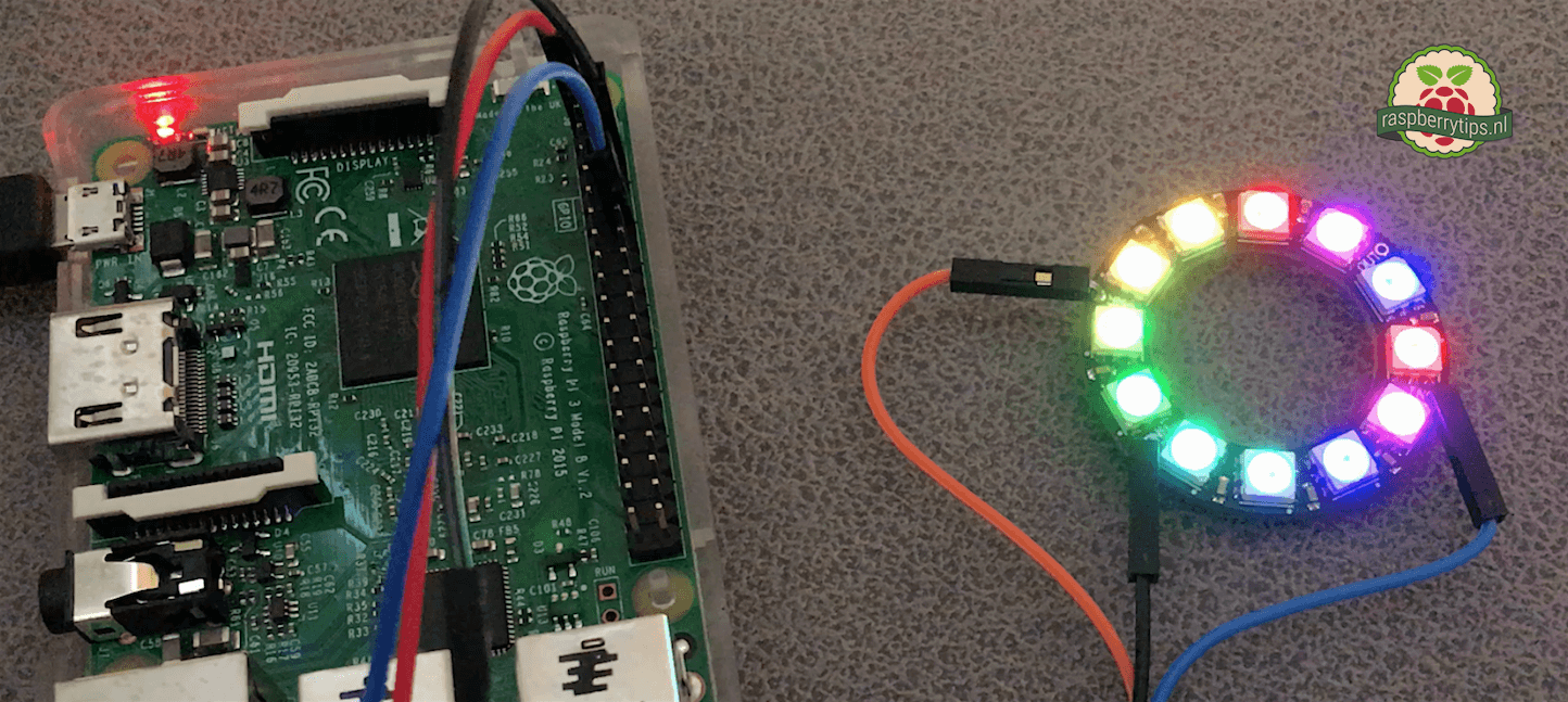
Een NeoPixel (WS2811) is een meerkleurige led met een hoog contrast, de leds kunnen op een Raspberry Pi met behulp van een Python script worden aangestuurd.
Adafruit Learning System
Make hardware and interface with sensors super easy using CircuitPython
all show my soap setup one moment
 grand sparrow
hello I want to create simple nodejs script for push button but it doesnt work
I followed this tutorial
and when Im holding the button nothing happens

W3Schools offers free online tutorials, references and exercises in all the major languages of the web. Covering popular subjects like HTML, CSS, JavaScript, Python, SQL, Java, and many, many more.
turbid rivet
@old parcel If you don't solder to the neopixel ring, you'll have to apply enough sideways pressure on the wires to maintain enough connection for it to work properly.
Even then, it won't be very reliable. Best to solder and get a good solder sucker if you need to make changes.
old parcel
turbid rivet
<@!177445849952026625> If you don't solder to the neopixel ring, you'll have to ...
ooh that's what i do wrong gotcha! will ask dad to solder then 🙂 (wanted to test b/c if i solder, they wouldn't return it i believe)
i'll wait a bit with that until i have a special case in (the person who send me the case also gave some wires and i wanna like style it a bit XD)
grand sparrow
Im using this code ```var Gpio = require('onoff').Gpio; //include onoff to interact with the GPIO
var pushButton2 = new Gpio(17, 'in', 'rising', {debounceTimeout: 10});
pushButton2.watch(function (err, value) {
//Watch for hardware interrupts on pushButton GPIO, specify callback function
if (err) { //if an error
console.error('There was an error', err); //output error message to console
return;
}
console.log("Btn2");
});```
old parcel
turbid rivet
<@!177445849952026625> If you don't solder to the neopixel ring, you'll have to ...
Is this the righ code with sudo?
import time
import board
import digitalio
print("hello blinky!")
led = digitalio.DigitalInOut(board.D18)
led.direction = digitalio.Direction.OUTPUT
while True:
led.value = True
time.sleep(0.5)
led.value = False
time.sleep(0.5)
For the rgbw ring 16 led?
lost wolf
old parcel
Is this the righ code with sudo?
import time
import board
import digitalio
pri...
Nope! That is for a single bare LED.
old parcel
(Were gonna try to apply more pressure to the ring solder points)
Oooh that’s maybe the reason why it didn’t work!
I’m looking online for an example to test the ring
But can’t find one sorry
lost wolf
You'll need to change the pin to match your setup.
Also you need to install the neopixel library.
old parcel
lost wolf
Also you need to install the neopixel library.
Did that!
Will try that link and follow those steps thank you!
I’m sorry for asking so many questions that are already available publvilly, the Uber guide was confusing for me
lost wolf
No worries! If you don't know what you're looking for, it's difficult to find things. 🙂
old parcel
yep xD
also, i believe i lost all my /lib files b/c of the moving of the lib folder sadly xD
have to reformat the whole os so it'll take a bit longer for me to test this out
old parcel
lost wolf
Also you need to install the neopixel library.
yeah pardon me on this part, i though that were the pip installs
lost wolf
old parcel
yeah pardon me on this part, i though that were the pip installs
There are. adafruit-circuitpython-neopixel I think. Which will automatically install Blinka etc.
old parcel
mm, so pip install adafruit-circuitpython-neopixel ?
lost wolf
I believe so, yes
old parcel
oo awsome will try that out after i did the initial setup (like opening ic2 etc, and the default adafruit pip)
old parcel
heya, i wanted to test it again (this time, i didn't move the lib to /lib
but i get this error:
vim therealtest.py
macley@delta-pi:~/adafruit-circuitpython-bundle-7.x-mpy-20220224 $ sudo python3 !$
sudo python3 therealtest.py
Traceback (most recent call last):
  File "/home/macley/adafruit-circuitpython-bundle-7.x-mpy-20220224/therealtest.py", line 8, in <module>
    import neopixel
ModuleNotFoundError: No module named 'neopixel'
i am inside the folder of the bundle, and made a python script, but i believe i'm not importing the lib correctly
i'm normally used to use apt, or that having the project cloned fully, it'll build/work (never used a libarly like this before)
lost wolf
old parcel
heya, i wanted to test it again (this time, i didn't move the lib to /lib
but i...
You have to pip install to run code locally on a Pi. You can't use the bundle copies of things. Even in the same directory.
old parcel
ooo ok, i'll remove that zip asap!
but, which pip am i'm forgetting?
sudo apt-get install python3-pip
sudo pip3 install --upgrade setuptools
sudo pip install adafruit-circuitpython-neopixel
sudo pip3 install --upgrade adafruit-python-shell
(also there's no python 2/pip2)
lost wolf
Um.... Does it install Adafruit-Blinka when you install neopixel?
old parcel
sudo pip install Adafruit-Blinka
Looking in indexes: https://pypi.org/simple, https://www.piwheels.org/simple
Requirement already satisfied: Adafruit-Blinka in /usr/local/lib/python3.9/dist-packages (7.0.1)
Requirement already satisfied: pyftdi>=0.40.0 in /usr/local/lib/python3.9/dist-packages (from Adafruit-Blinka) (0.53.3)
Requirement already satisfied: Adafruit-PureIO>=1.1.7 in /usr/local/lib/python3.9/dist-packages (from Adafruit-Blinka) (1.1.9)
Requirement already satisfied: rpi-ws281x>=4.0.0 in /usr/local/lib/python3.9/dist-packages (from Adafruit-Blinka) (4.3.2)
Requirement already satisfied: Adafruit-PlatformDetect>=3.13.0 in /usr/local/lib/python3.9/dist-packages (from Adafruit-Blinka) (3.20.0)
Requirement already satisfied: RPi.GPIO in /usr/local/lib/python3.9/dist-packages (from Adafruit-Blinka) (0.7.1)
Requirement already satisfied: sysv-ipc>=1.1.0 in /usr/local/lib/python3.9/dist-packages (from Adafruit-Blinka) (1.1.0)
Requirement already satisfied: pyserial>=3.0 in /usr/lib/python3/dist-packages (from pyftdi>=0.40.0->Adafruit-Blinka) (3.5b0)
Requirement already satisfied: pyusb!=1.2.0,>=1.0.0 in /usr/local/lib/python3.9/dist-packages (from pyftdi>=0.40.0->Adafruit-Blinka) (1.2.1)
nope!
old parcel
hmm, strange (sorry i still don't see neopixel in that output)
lost wolf
No, Blinka doesn't auto install neopixel, other way around.
old parcel
oh wait, moving it to the cd ~ gives now this:
python3 therealtest.py
Traceback (most recent call last):
  File "/home/macley/therealtest.py", line 10, in <module>
    pixel_pin = board.A1
AttributeError: module 'board' has no attribute 'A1
ooh i see
lost wolf
You need to update it to match the pin for the Pi that your ring is connected to
I have to head out. Hopefully this gets you fixed up. If not, post here and someone will hopefully be able to assist.
old parcel
sure thing! thank you so much for everything! i noted every singel step from the brand new os! thanks!
So far all the libs are in working order, it seems i'm not understanding what this error means:
python3 therealtest.py
Traceback (most recent call last):
  File "/home/macley/therealtest.py", line 10, in <module>
    pixel_pin = board.A1
AttributeError: module 'board' has no attribute 'A1
i'm using this test script to see if this ring works:
https://www.adafruit.com/product/2856
# SPDX-FileCopyrightText: 2018 Kattni Rembor for Adafruit Industries
#
# SPDX-License-Identifier: MIT

"""CircuitPython Essentials NeoPixel RGBW example"""
import time
import board
import neopixel

pixel_pin = board.A1
num_pixels = 16

pixels = neopixel.NeoPixel(pixel_pin, num_pixels, brightness=0.3, auto_write=False,
                           pixel_order=(1, 0, 2, 3))


def colorwheel(pos):
    # Input a value 0 to 255 to get a color value.
    # The colours are a transition r - g - b - back to r.
    if pos < 0 or pos > 255:
        return (0, 0, 0, 0)
    if pos < 85:
        return (255 - pos * 3, pos * 3, 0, 0)
    if pos < 170:
        pos -= 85
        return (0, 255 - pos * 3, pos * 3, 0)
    pos -= 170
    return (pos * 3, 0, 255 - pos * 3, 0)


def color_chase(color, wait):
    for i in range(num_pixels):
        pixels[i] = color
        time.sleep(wait)
        pixels.show()
    time.sleep(0.5)


def rainbow_cycle(wait):
    for j in range(255):
        for i in range(num_pixels):
            rc_index = (i * 256 // num_pixels) + j
            pixels[i] = colorwheel(rc_index & 255)
        pixels.show()
        time.sleep(wait)


RED = (255, 0, 0, 0)
YELLOW = (255, 150, 0, 0)
GREEN = (0, 255, 0, 0)
CYAN = (0, 255, 255, 0)
BLUE = (0, 0, 255, 0)
PURPLE = (180, 0, 255, 0)

while True:
    pixels.fill(RED)
    pixels.show()
    # Increase or decrease to change the speed of the solid color change.
    time.sleep(1)
    pixels.fill(GREEN)
    pixels.show()
    time.sleep(1)
    pixels.fill(BLUE)
    pixels.show()
    time.sleep(1)

    color_chase(RED, 0.1)  # Increase the number to slow down the color chase
    color_chase(YELLOW, 0.1)
    color_chase(GREEN, 0.1)
    color_chase(CYAN, 0.1)
    color_chase(BLUE, 0.1)
    color_chase(PURPLE, 0.1)

    rainbow_cycle(0)  # Increase the number to slow down the rainbow
NOTE: i did notice the number of pixels was 8, changed that to 16. But can someone help me what i need to look for with the board missing the A1 module?
wiring is done as shown here:
https://raspberrytips.nl/neopixel-ws2811-raspberry-pi/
What is better than smart RGB LEDs? Smart RGB+White LEDs! These NeoPixel rings now have 4 LEDs in them (red, green, blue and white) for excellent lighting effects. Round and round and round ...
Een NeoPixel (WS2811) is een meerkleurige led met een hoog contrast, de leds kunnen op een Raspberry Pi met behulp van een Python script worden aangestuurd.
tired marsh
A1 is a pin name, there is no pin named A1, what pin are you using ?
ah with that wiring, that would be board.D18
tired marsh
old parcel
So far all the libs are in working order, it seems i'm not understanding what th...
so you would need to change the pin definition to:
pixel_pin = board.D18
if you type dir(board) you'll see the list on pins, D* is GPIO* in the pinout https://pinout.xyz/#
 pure hill
Hey everyone! Just a quick question, so I bought the Adafruit bno055 IMU and I have a Raspberry Pi 3B+ running Ubuntu 20.04 (64-bit). Most of the tutorials seem outdated and so I was wondering whether I should use i2c or uart to connect to the IMU? There are some posts about an i2c clock-stretching problem, is that still a problem.
 hardy plaza
I don't use Ubuntu on a Raspberry Pi, nor can I recommend it, but certainly the BNO055 (and BNO08x) can be connected via I2C, and there are software libraries for that purpose. I've been using various BNOx IMUs for years now, all connected over I2C and never messed with the system clock speed.
...put it this way: try it out and if you don't run into a problem don't mess with system fundamentals like I2C bus speed as that will effect the performance of other I2C peripherals.
ruby night
pure hill
Hey everyone! Just a quick question, so I bought the Adafruit bno055 IMU and I ...
Have you looked at this guide https://learn.adafruit.com/circuitpython-on-raspberrypi-linux/i2c-clock-stretching. It discusses I2C clock stretching with the bno055 on a pi, but it may only apply to RaspiOS. I don’t know what if there is a bno055 library for Ubuntu. Maybe you can use Blinka to be able to use CIrcuitPython library.
hardy plaza
There won't be any Python-based differences between Raspberry Pi OS and Ubuntu as they both use the Linux kernel (likely even the same version), so the only difference may be the Python version. I am aware of clock-stretching, I'm just saying that I've never done it, nor needed to. I can't comment on CircuitPython as I don't use it, only CPython and MicroPython. If you're running this on a Raspberry Pi you won't need CircuitPython as you'll be using CPython (i.e., the installed Python on the Raspberry Pi OS and Linux generally).
Actually, a correction: I looked in my code and I'm using the adafruit-circuitpython-bno055 library, though my core code is CPython. See: https://github.com/ifurusato/ros/blob/master/lib/bno055.py

GitHub
A Python-based Robot Operating System (ROS). Contribute to ifurusato/ros development by creating an account on GitHub.
 visual crescent
How do you connect a mouse and keyboard to a Pi Zero 2 W since it only has one usb input? A Hub?
hardy plaza
visual crescent
How do you connect a mouse and keyboard to a Pi Zero 2 W since it only has one u...
Yes, a USB hub works fine. Though if you have a Bluetooth mouse or keyboard you might note that the Raspberry Pi Zero 2 W does have Bluetooth, but there's a bit of a chicken-and-egg thing going because you need to be able to pair the Bluetooth device to be able to use it, and for that you'll likely need a keyboard and a mouse. But once set up you can just use Bluetooth.
visual crescent
What kind of keyboard is suited for Raspbian that will be used mainly for coding other projects? I wanted a build a 60 percent but now am worried about needing Fn keys or the arrow keys
 zinc jackal
Full-size is correct size.
visual crescent
zinc jackal
Full-size is correct size.
Making a portable device, it's either less than full sized or non at all sadly
zinc jackal
Ooof
visual crescent
Anyway, the question was, do I need Fn keys or the arrow keys for Raspbian Coding. I already have a Full sized keybaord at home when I actually have space lol
ruby night
hardy plaza
There won't be any Python-based differences between Raspberry Pi OS and Ubuntu a...
My comment about using the CIrcuitPython library in the pi was related to the need for the adafruit_blinka library. It allows CIrcuitPython libraries to be run from CPython on the pi and other computers. I just don’t know if that supports Ubuntu on the Pi.
The bno055 lib may not need blinka. It depends on its dependencies.
hardy plaza
visual crescent
Making a portable device, it's either less than full sized or non at all sadly
I use a sub-size Rapoo radio-remote keyboard with the little USB dongle so I can type into the console on the Pi with a Pi MiniTFT display. But I would never code that way.
Instead, I'd recommend remoting from a laptop or desktop into your Pi over ssh to do your coding and not connecting a keyboard to it at all. If you properly set up ssh keys you don't even need to use a password to connect. So I can open a normal terminal window on Ubuntu and ssh in securely with no password at all.
hardy plaza
visual crescent
Anyway, the question was, do I need Fn keys or the arrow keys for Raspbian Codin...
Why would coding on Raspbian (which is now called the Raspberry Pi OS) be any different than any other coding?
ruby night
Blinka provides in interface to some CircuitPython "core" modules like board and busio. Glancing at the bno055 lib I don't see any use of those, so it may be just Cpython.
visual crescent
hardy plaza
I use a sub-size Rapoo radio-remote keyboard with the little USB dongle so I can...
Building a raspberry pi laptop actually, cheaper in my case. Just wondering about the keyboard rn
visual crescent
hardy plaza
Why would coding on Raspbian (which is now called the Raspberry Pi OS) be any di...
I've never coded before, asking people with experience
Never used Pi OS before either so idk much about the OS
Wanted to use the Pi Zero 2 W as a core for the laptop, figured I wouldn't need much since I only want to code on it
hardy plaza
Well, I've been a software developer since the 1980s. The most important thing for anyone who is going to be spending hundreds or even thousands of hours coding is proper ergonomics. That means a proper monitor whose center is just slightly below eye level, a proper full sized keyboard, and a decent mouse. You elbows should be relatively horizontal and you should not be resting your palms on the table nor your forearms even touching the table. Proper lighting. Basic ergonomics. That's probably the best advice I can give you. Your health is important. When you're young you generally think you're indestructable, and you're not. I've known several people who've blown out their wrists and can no longer type at all (and are now using voice software).
If you're on a Raspberry Pi you're on a Linux computer, with basically all the features of a Linux computer.
The Pi Zero 2 W is a fine small computer and has four cores, not a lot of memory but enough for some tasks. If you're going to use a desktop rather than console then maybe bump up to a Pi 3 B+ with a proper 1GB of memory. But you don't need a desktop environment to code on a Pi. I do all my coding from a terminal window remoting into my Pis.
I have a git repository and I push all my project code to github as I'm working so there's no danger of me losing my work.
visual crescent
hardy plaza
Well, I've been a software developer since the 1980s. The most important thing f...
I'm building it to do small stuff portably at a restaurant job, I can't be bringing a full sized keyboard and monitor, it's only on my time off, not for hours on end.
Was thinking of using my phone as a display
hardy plaza
Would you be comfortable not having a desktop? Just a terminal window?
visual crescent
Maybe, worth a try. Still a good project to learn stuff either way
ruby night
Keeping good backups is critical -- I try to never assume my code will be there when I come back after I power off a Pi or a Microcontroller..
hardy plaza
visual crescent
Maybe, worth a try. Still a good project to learn stuff either way
Yeah, sure. Coding is a combination of your skills and your tools. The better you get with both the better a coder you are. But those tools can be almost anything. I spend the vast majority of my time on my own projects in Python using a vi editor, for my day job using Java inside an Eclipse IDE. Very different environments, very different tools, same brain. As you gain experience you layer new things onto the old.
visual crescent
hardy plaza
Would you be comfortable not having a desktop? Just a terminal window?
Why, are you going to suggest ssh? Place doesn't have wifi, not an option
hardy plaza
ruby night
Keeping good backups is critical -- I try to never assume my code will be there ...
No WiFi?
visual crescent
Yes, no WiFi
hardy plaza
How big a display do you plan to use?
visual crescent
I would need internet for a remote thing, right?
hardy plaza
Yes, you'd need WiFi or an Enternet connection to get to the internet.
visual crescent
hardy plaza
How big a display do you plan to use?
No idea, my phone is about 6 inches, I could get those cheap 7" displays too that would be slightly taller
hardy plaza
iPhone or Android?
I think you're going to find using your phone very difficult. You'd be better finding the largest HDMI display you're comfortable carrying with you.
In any case, I just realised it's very late here so I've got to head to bed.
visual crescent
hardy plaza
In any case, I just realised it's very late here so I've got to head to bed.
Take care, good night
hardy plaza
So in summary, if there's no internet you're not going to have access to software libraries or updates, no ability to push your code to a safe repository or backup. Not while you're at the restaurant, but when you get home you can. I'd say use an HDMI display, a radio-style USB keyboard. If you are console only (recommended on the limited power of the Pi Zero 2 W) then you won't need a mouse. When you get home you can ssh into the Pi from a laptop or desktop and from the Pi itself push your code to github or at least archive a copy of your code regularly to a proper backup medium.
I sometimes code while on a train using a MacBook 12, one of those tiny laptops. No connection. So when I do have a connection I'm updating and downloading libraries, getting set up for no connection while on the train. When I get home at night I sync everything back up.
'night
visual crescent
Do F keys(F1,F2) and Numberpad/Arrow-keys become a necessity in coding or something, still confused about that bit
hardy plaza
If you're using a console you'll seldom if ever need function keys as they're mostly a desktop feature. You will want arrow keys though. Most small keyboards have arrow keys, though some make you hold down a modifier to use them, which is annoying. If you can get a keyboard with proper arrow keys get that.
This is the keyboard I use when I need a portable one: https://www.adafruit.com/product/2876

The quick brown fox jumps over the lazy dog. The quick brown fox jumps over the lazy dog. The quick brown fox - sorry! We were practicing our typing ON THIS AWESOME KEYBOARD.With ...
My normal keyboard is a Cherry MX BOARD 3.0S, just today replacing an earlier SteelSeries 6Gv2 whose keys finally gave out. I use MX Black mechanical keys, which are loud but fast. I find even the MacBook frustrating to type on, and those tiny portable keyboards just too difficult to do anything apart from type commands and things, never code. But you're certainly welcome to try.
https://www.cherry-world.com/cherry-mx-board-3-0-s.html

Expect to win!
Accessories MX BOARD 3.0S
anyway, it's 3:05am so 'night finally
visual crescent
Making a custom keyboard, so I should be able to do everything that's needed, only problem was knowing what was needed. Thanks, I'll integrate a arrow-key ouo
visual crescent
mystic spindle
<@!288259088922443777> Just get a pi 400
Too expensive, did look at it tho. Costs Hundreds here I think, 600 minimum
mystic spindle
what dev do u plan on doing
anything visual or web you can kiss that goodbye on a pi zero
visual crescent
mystic spindle
anything visual or web you can kiss that goodbye on a pi zero
Microcontroller coding based on DisplayIO on CircuitPython, would you say it's not okay?
mystic spindle
That should be fine as long as u can run console only
visual crescent
mystic spindle
That should be fine as long as u can run console only
Console only is like Linux without the GUI right? Still new to the keywords ouo
 opaque wagon
visual crescent
Console only is like Linux without the GUI right? Still new to the keywords ouo
opaque wagon
visual crescent
Console only is like Linux without the GUI right? Still new to the keywords ouo
Yes, just text
There are many text based editors
 vapid python
I do a lot of work on my pis over ssh using an old Chromebook w Linux on it. It's much more streamlined (no wires), gets me a large display for cheap, and still has good battery life.
opaque wagon
opaque wagon
Yes, just text
There are many text based editors
(for example, nano, vim, micro)
vapid python
No idea where you are located, but in the US you can get an old Chromebook like the c720 for the same price or less than a Pi4 (which aren't in stock anywhere)
visual crescent
opaque wagon
Yes, just text
There are many text based editors
Thank you!
visual crescent
vapid python
I do a lot of work on my pis over ssh using an old Chromebook w Linux on it. It'...
Can't ssh, no internet where I am going to use it
vapid python
You don't need internet to ssh. You could create a wireless hotspot (for a network connection) on the pi itself, your phone, or even use a serial cable
With the pi zero you can even setup networking over the USB OTG port
visual crescent
Oh, that's what you meant 😄
 trim umbra
does anyone know if there are animation libraries that handle animations on the raspberry pi in python or do i need to calculate them out myself
umbral sable
trim umbra
does anyone know if there are animation libraries that handle animations on the ...
You might look at frameworks like PyGame, for example.
trim umbra
umbral sable
You might look at frameworks like PyGame, for example.
i meant for the neopixels, should have specified
old parcel
tired marsh
so you would need to change the pin definition to:
```py
pixel_pin = board.D18
`...
oooh gotcha! i do get that my board is unsupported now, but there's a pr for that to fix that
gonna see if i can manage to fetch that pr!
old parcel
@tired marsh @lost wolf @ruby night thank you all so much for your help!
when i fixed the script i noticed i was getting the same error i had with this lib:
https://github.com/jgarff/rpi_ws281x
luckily another guy added some code into a PR and by compiling that and using the included demo it worked in one go!
https://github.com/jgarff/rpi_ws281x/pull/492
i do really hope it's possible to merge this pull as i can't wait to use the script outside of that cloned project and continue experimenting!
are there more example scripts i can read trough to come up with how to like time my lights etc? (like don't play after 11pm, or use a static one light, or slowly transition from one color to the next forever?
Again thank you all for this, i'm really happy that the ring works! and given the intense light... well i'm sure 3.3v is more then enough to drive them XD my eye's still hurt haha (also the 64-bit warning can be removed from the official docs maybe? correct me if i'm wrong!)

GitHub
Userspace Raspberry Pi PWM library for WS281X LEDs - GitHub - jgarff/rpi_ws281x: Userspace Raspberry Pi PWM library for WS281X LEDs

GitHub
Adds support for the 4GB pi 4 v1.5 based on the details provided in the comment here
lost wolf
old parcel
<@!199811382793863168> <@!330227457296957440> <@!343570430042308609> thank you a...
The Adafruit Learn System has a lot of NeoPixel examples. Most are RGB, but you can make them RGBW by following the explanation in the first guide link I sent you. (Basically adding another tuple member at the end of the RGB number, i.e. (255, 255, 255, 0).) Check out the LED Animation library. I'm fairly certain it works on RPi, but I haven't tested it. Also, fairly sure it supports RGBW, but I don't recall for sure.
pure hill
Hey everyone! My raspberry pi (3B+) doesn't seem to detect i2c with the bno055 IMU. I just connected the pi with my arduino and tried turning a led on over i2c and it worked perfectly. The wiring should be good so I'm a little surprised that it doesn't detect the i2c. When I used my Arduino, I set it at 0x8 and when I ran i2cdetect -y 1, it returned something at 0x8. Right now, this is all I get when I run i2cdetect. Does anyone know what could be going on?
 old parcel
lost wolf
The Adafruit Learn System has a lot of NeoPixel examples. Most are RGB, but you ...
old parcel
lost wolf
The Adafruit Learn System has a lot of NeoPixel examples. Most are RGB, but you ...
ooh sure sure, i just found that link again and saved it
i'll see if i can find the ALS and study how it works 🙂 ❤️
lost wolf
old parcel
ooh sure sure, i just found that link again and saved it
i'll see if i can find...
https://learn.adafruit.com and search for NeoPixel. There is an "Uberguide" which isn't what you want or need right now. You're past that. Check out various project guides instead.
old parcel
mhmhm, btw really nice website, love how you guys make easy but not to distracting gifs of the projects
trim umbra
just gonna ask again because my question got burried, is there a python animation library for the neopixels or do i need to hardcode them myself?
lost wolf
trim umbra
just gonna ask again because my question got burried, is there a python animatio...
There is a CircuitPython LED Animation library, which with the help of the compatibility layer Blinka, can be used on Raspberry Pi (as far as I know, I haven't tested it personally, but I don't think there's a reason it wouldn't.). I don't know about whether there is a CPython animation library. We wrote one for CP, so I haven't needed to look for a Python one.
lost wolf
Installation instructions https://github.com/adafruit/Adafruit_CircuitPython_LED_Animation#installing-from-pypi
GitHub
CircuitPython helper library for LED colors and animations - GitHub - adafruit/Adafruit_CircuitPython_LED_Animation: CircuitPython helper library for LED colors and animations
trim umbra
thankyou
pure hill
Hey! Does anyone know how I could test whether my bno055 IMU is broken? I tested whether the voltage and ground are connected correctly by letting it light a LED so that should be okay
pure hill
yup, you mean i2c right?
pure hill
Yeah haha. I'm not sure what to do at this point... I must say, I'm not the greatest solderer and I was using a really bad soldering iron so is it possible that I damaged the IMU like irreversibly?
trim umbra
any direct contact with the pcb at high temps for a long period of time has a chance of damaging the onboard components
but normally isnt too bad
pure hill
Well this sucks haha. I'm still in high school at the moment and I'm doing like a special project my school started. I have an "instructor" that gives me these things I have to do and reading an IMU is one of them, I really wanted to get it done asap but if it's damaged it'll take me another couple of days
ruby night
pure hill
Well this sucks haha. I'm still in high school at the moment and I'm doing like ...
Can you post a picture of the soldering? Also, have you ever used the I2C on this Raspberry Pi just o be sure it is OK -- Third, have you tried running the "simpletest " on the bno055 even though the I2C scan does not report it. There have been issues with the scan in the past. The bno055 is can be difficult on a pi. Have you been following htis guide ? https://learn.adafruit.com/adafruit-bno055-absolute-orientation-sensor/python-circuitpython
pure hill
ruby night
Can you post a picture of the soldering? Also, have you ever used the I2C on thi...
I used i2c to communicate with an arduino earlier today so it should work perfectly fine. When I connected the arduino, running i2cdetect -y 1 also returned the i2c address of the arduino if you know what I mean. I haven't tried running simpletest but I'll test it out now! I've used multiple guides, this one being the latest: https://cdn-learn.adafruit.com/downloads/pdf/adafruit-bno055-absolute-orientation-sensor.pdf but I'll try out the simpletest and your guide now!
I'll send a picture of the soldering in a moment
ruby night
Have you installed "blinka" on your Pi?
pure hill
yes
I know the soldering kinda sucks but I had a really crappy soldering iron okay haha
ruby night
The scan you posted shows I2C devices at 0x60 and 0x70 -- what are those?
pure hill

 pure hill
ruby night
The scan you posted shows I2C devices at 0x60 and 0x70 -- what are those?
pure hill
ruby night
The scan you posted shows I2C devices at 0x60 and 0x70 -- what are those?
I don't know actually, how can I find out? Could it maybe be an Adafruit motorshield I have on the PI?
ruby night
pure hill
I don't know actually, how can I find out? Could it maybe be an Adafruit motorsh...
this might help https://learn.adafruit.com/i2c-addresses
pure hill
https://www.adafruit.com/product/1438 This is the shield I'm using, I couldn't find it in the list though
thanks for helping me btw, means a lot
oh yeah

Are both the shield or can it only be one?
ruby night
The soldering could be a problem . If you have access to the soldering iron again, you could try reheating the connections to get the solder to flow better. It does not look like you need to add any solder except maybe to the RST pin. The VIN looks particularly suspect.
ruby night
pure hill
Are both the shield or can it only be one?
I think it only uses one.
pure hill
Alright, apparently we got a new one and I used the old one. So I'll try resoldering tomorrow and just quickly try out the simpletest and tutorial you sent me
ruby night
Good luck!
pure hill
Thanks! :)
 mystic wharf
Hi! I recently tried going through this tutorial to get circuit python on my pi pico https://learn.adafruit.com/circuitpython-libraries-on-micropython-using-the-raspberry-pi-pico/thonny-setup but it looks like the micropython that is installed is based on 3.4.0 and the adafruit_platformdetect library uses the typing module which doesn't seem to exist in this implementation of python. Any suggestions on where to go from here?
humble marsh
mystic wharf
Hi! I recently tried going through this tutorial to get circuit python on my pi ...
you can install CircuitPython directly on the Pi Pico. It's a lot less convoluted than using Blinka on top of MicroPython. https://learn.adafruit.com/getting-started-with-raspberry-pi-pico-circuitpython
mystic wharf
hmm fair. I had used it this way for a different project and I guess it worked not bad. Since I want to use some of the circuitpython libraries, this seems is the easiest way. Thanks!
that being said, I feel like the tutorial I followed is maybe obsolete at this point? or maybe it needs to specify older versions of adafruit_platformdetect?
tired marsh
platformdetect should be fixed to try/catch on import typing, you can try removing the imports
steady rose
@pure hill not sure this was mentioned, but for using the BNO055 with a Pi, be sure and do this:
https://learn.adafruit.com/circuitpython-on-raspberrypi-linux/i2c-clock-stretching
there are warnings in the BNO55 that call this out:
https://learn.adafruit.com/adafruit-bno055-absolute-orientation-sensor/python-circuitpython#python-computer-wiring-i2c-2998129-5
pure hill
steady rose
<@!426419628156387328> not sure this was mentioned, but for using the BNO055 wit...
Will check it out! Thanks!
pure hill
steady rose
<@!426419628156387328> not sure this was mentioned, but for using the BNO055 wit...
Just enabled clock stretching, still doesn't work. I'll try resoldering tomorrow, it's getting late now. good night!
thanks for the help everyone!
mystic spindle
trim umbra
i meant for the neopixels, should have specified
I think displayIO does? not sure, Only really used Pillow
 robust tangle
Hi can you tell me what version of circuitpython in need to download to use on a RPi 3b+ plz? there i cant find 3b+ in the list
Many thanks
 tired marsh
robust tangle
Hi can you tell me what version of circuitpython in need to download to use on a...
tired marsh
robust tangle
Hi can you tell me what version of circuitpython in need to download to use on a...
Circuitpython does not run bare metal on the Pi 3, only models that have USB OTG. Are you looking for Blinka (Circuitpython libraries on linux) ?
https://circuitpython.org/blinka
robust tangle
Thanks
pure hill
ruby night
The soldering could be a problem . If you have access to the soldering iron agai...
Thank you so much for your help! I used a new (better) solder iron today and it detects the sensor!
ruby night
pure hill
Thank you so much for your help! I used a new (better) solder iron today and it ...
yay!
old parcel
not sure where to ask this
but this library: https://github.com/jgarff/rpi_ws281x
is used by adafruit in blanka or?

GitHub
Userspace Raspberry Pi PWM library for WS281X LEDs - GitHub - jgarff/rpi_ws281x: Userspace Raspberry Pi PWM library for WS281X LEDs
i was wondering which pip install added this library and how
because there's a bug fix that i would like to in the production (not community) of adafruit's libraries
steady rose
it gets installed when you install blinka, via the requirement:
https://github.com/adafruit/Adafruit_Blinka/blob/bd30f6a64bb61b7778fde4690428e5628d0bb725/requirements.txt#L5
any updates to rpi_ws81x need to be released first, by that library
and then you could update blinka to pull in latest
for example, if you're wanting blinka to have this:
https://github.com/jgarff/rpi_ws281x/pull/492
you'll have to wait for that PR to be merged and released
and that's entirely up to the maintainers of the rpi_ws281x repo
 midnight stone
could i connect a raspberry pi zero 2 w safely to a 6V power source
i read that it operates between 4.75v and 5v
 rough forge
i have a pca9685 servo shield and a raspberry pi 2b to drive 9 servos.
when i move the servos in software, the servos move, but not at the same time. the move one after another.
this is my code: ```python
from future import division
import time
import Adafruit_PCA9685
pwm = Adafruit_PCA9685.PCA9685()
def set_servo_pulse(channel, pulse):
pulse_length = 1000000 # 1,000,000 us per second
pulse_length //= 60 # 60 Hz
print('{0}us per period'.format(pulse_length))
pulse_length //= 4096 # 12 bits of resolution
print('{0}us per bit'.format(pulse_length))
pulse *= 1000
pulse //= pulse_length
pwm.set_pwm(channel, 0, pulse)
pwm.set_pwm_freq(60)

print('Moving servo on channel 0, press Ctrl-C to quit...')
while True:
pwm.set_pwm(0, 0, 90)
pwm.set_pwm(1, 0, 90)
pwm.set_pwm(2, 0, 90)
pwm.set_pwm(3, 0, 90)
pwm.set_pwm(4, 0, 90)
pwm.set_pwm(5, 0, 90)
pwm.set_pwm(6, 0, 90)
pwm.set_pwm(7, 0, 90)
time.sleep(1)
pwm.set_pwm(0, 0, 635)
pwm.set_pwm(1, 0, 635)
pwm.set_pwm(2, 0, 635)
pwm.set_pwm(3, 0, 635)
pwm.set_pwm(4, 0, 635)
pwm.set_pwm(5, 0, 635)
pwm.set_pwm(6, 0, 635)
pwm.set_pwm(7, 0, 635)
time.sleep(1)```
is there something wrong with my code or can the shield do only one servo at a time?
umbral sable
There is a set_all_pwm() call to do them all at once, but I'd ordinarily expect that the sequential calls would be fast enough to not notice with human senses. How much of a time lag are you seeing?
rough forge
from first servo moving to last servo moving about 2 seconds id say
i can send a video if you want
umbral sable
That's very unexpected. You've got a 2-second loop in total in the code. Does the back-and-forth go slower than that?
rough forge
nope
i modified the code so it runs with dmx values, and it is still delayed
import sacn
import Adafruit_PCA9685
print("Import completed")


receiver = sacn.sACNreceiver()
receiver.start()
pwm = Adafruit_PCA9685.PCA9685()

def set_servo_pulse(channel, pulse):
    pulse_length = 1000000    # 1,000,000 us per second
    pulse_length //= 60       # 60 Hz
    print('{0}us per period'.format(pulse_length))
    pulse_length //= 4096     # 12 bits of resolution
    print('{0}us per bit'.format(pulse_length))
    pulse *= 1000
    pulse //= pulse_length
    pwm.set_pwm(channel, 0, pulse)
    pwm.set_pwm_freq(60)

print("Started")

# define a callback function
@receiver.listen_on('universe', universe=1)
def callback(packet):
    for i in range(9):
        pwm.set_pwm(i, 0, int(90 + ((packet.dmxData[i]*100/255)/100) * (635-90)))
print((packet.dmxData[i]))```Any chance your I2C setup is accidentally using a ridiculously low frequency, like 100 Hz instead of 100kHz?
rough forge
where can i check that?
umbral sable
It looks like you're just using the default I2C initializer, so that's probably not it. But I am confused. You might some quick timing tests like:```import time
start = time.time()
for i in range(9):
...
print(time.time() - start)```
umbral sable
That's what I'd expect, less than a millisecond to go through the loop. So the servos should be getting their signals quickly. Not sure why there would be a delay.
The only thing that pops to mind is that your power supply might be browning out when too many servos are moving at once, so the later ones can't draw enough power to start moving until the first ones stop, or something like that. If you have a multimeter you might check the power rail voltage while this is going on.
rough forge
oh 1 sec i have no power supply connected rn
but i tested it with power supply so it should work
i mean not work but not be different
umbral sable
I'm not following. What's powering the servos right now?
rough forge
only the raspberry
umbral sable
That's probably not going to be sufficient for 9 running at once. Motors really ought to have their own power.
rough forge
i tested it previously only on a esp8266 and external power supply. that didnt worked
raspberry and power supply works
thanks for your help
and sorry for my stupidity not to connect a power supply
no wait
it is still not completely synced.
its just a lot better but there is still about half a second of delay between the movement
old parcel
steady rose
any updates to `rpi_ws81x` need to be released first, by that library
Does that mean an update to the master repo or do they need to make a release?
Or does a fork of that repo need to@make a new release? Then I can contact the maintainers to get that going and all 🙂
 iron kestrel
hello guys, I'm a student working on a project with raspberry pi for my bachelor's degree, and currently I am stuck trying to figure out if there is any way to get a 5v relay working? I saw only around two results on the web that used NPN transistors and resistors to convert from 3v3 to 5v, and I have those only the schemes were not matching (the electrical diagram and fritzing diagram), so I'm not trustworthy. Can you offer me any help?
old parcel
iron kestrel
hello guys, I'm a student working on a project with raspberry pi for my bachelor...
while i can'thelp directly with this question, i had something simalair.
may i ask why you need 5v? given you ask it in adafruit's discord i assume ya want to power one of their products?
iron kestrel
old parcel
while i can'thelp directly with this question, i had something simalair.
may i ...
actually a relay that is not from adafruit, it was included in the plusivo kit for raspberry pi. From adafruit I have a DHT11 Temperature sensor that I also can't get it to work
and according to the research I have made, it seems like the relay is rated for 5V, so this means he sees output low even when sending 3V signal, I don't know if I explained very good, not my native language
olive haven
iron kestrel
actually a relay that is not from adafruit, it was included in the plusivo kit f...
The simplest way to deal with this would be a level shifter, like https://www.adafruit.com/product/1787.
iron kestrel
olive haven
The simplest way to deal with this would be a level shifter, like <https://www.a...
okay, thanks, will get one first thing monday
old parcel
iron kestrel
and according to the research I have made, it seems like the relay is rated for ...
it's ok, i actually kinda had a simalair issue with the 3.3v pins with a v5 needed device
that's as far as i could relate/help, but rimwolf's answer is the right one for sure
iron kestrel
thanks
but since you guys are here, one more question for tonight

i can't get the machine library
installed micropython and everything (I read it is included in micropython)
for the DHT11
olive haven
The Raspberry Pi runs full Python, not MicroPython, so you need a library for that. See this article: https://www.thegeekpub.com/236867/using-the-dht11-temperature-sensor-with-the-raspberry-pi/
iron kestrel
with that version I get only the errror, and I do the wiring good
olive haven
what error?
iron kestrel
Sensor failure. Check wiring.
it never reads
according tot the debugger
always skips the if
olive haven
Do you have its VCC connected to 5V? According to this page https://learn.adafruit.com/dht/connecting-to-a-dhtxx-sensor, "sometimes 3.3V power isn't enough"
iron kestrel
yes, followed the instructions from adafruit
yesterday i tried both
i tried with adafruit library and also pigpio
is there any way the sensor is faulty being brand new?
olive haven
It's always possible. I don't know that particular part
so I don't really know how you would troubleshoot it.
ruby night
iron kestrel
installed micropython and everything (I read it is included in micropython)
There is a CircuitPyhon Library for the DHT11 and DHT22 -- you can use it on a Raspberry Pi if you first install "Blinka" https://learn.adafruit.com/circuitpython-on-raspberrypi-linux
But be forewarned, the DHT sensors can be frustrating on a Pi.
hardy plaza
iron kestrel
hello guys, I'm a student working on a project with raspberry pi for my bachelor...
It's not clear from your description if the solution is part of your project or you simply need a controllable relay. If the latter, here's an option: https://shop.pimoroni.com/products/ht0740-breakout?variant=29453796606035

Oh boy, this is a Big. Damn. Switch. Program it to switch loads up to 40V / 10A connected to the HT0740 breakout's sturdy screw terminals, and use up to four breakouts at the same time using the configurable I2C addresses. Great for home automation.
These are I2C/CPython-controlled fully-isolated electronic (not mechanical) switches. Work like a charm, I've used them for several years.
 lofty charm
Hello, I have been trouble shooting how to figure how to get both my device with i2c communication to work. I figured out the issue is that they both share the same i2c 0x68 address and came to the conclusion that I need a i2c multiplexer https://www.adafruit.com/product/2717?gclid=CjwKCAiAvOeQBhBkEiwAxutUVM4tzCFfjHtHW_LdC7iPCs3fzR0OYYpFb3VDYw2gyad_ME89HEZ6BRoCArkQAvD_BwE. I have this raspberry pi ups hat https://www.pishop.us/product/raspberry-pi-ups-hat/ and this Adafruit accelerometer https://www.adafruit.com/product/4464. My question If I would to get the i2c multiplexer. I have my UPS HAT connected straight into the Raspberry Pi GPIO pins or does the UPS HAT need to be on a bread to connect to the i2c multiplexer with the accelerometer as well? Also is there alternative UPS HAT that work with my accelerometer so I don't need the i2c multiplexer?

You just found the perfect I2C sensor, and you want to wire up two or three or more of them to your Arduino when you realize "Uh oh, this chip has a fixed I2C address, and from what I ...

PiShop.us
American Raspberry Pi Shop. One stop shop for all your Pi needs. Raspberry Pi add-ons, HATs, accessories, Starter Kit, Media Center kit, RetroPi Arcade kit, Ultimate Kit, and many other project kits. PiShop.us is approved Raspberry Pi re-seller and carries all official Raspberry Pi boards and products.
umbral sable
lofty charm
Hello, I have been trouble shooting how to figure how to get both my device with...
On the back side of the accelerometer board, there's a solder-pad jumper labeled AD0. If you put a blob of solder across those, it'll change the I2C address to 0x69 to avoid conflicts.
 normal vale
Might anyone know why EGL is able to GetDisplay, but unable to Initialize with the returned(valid) display handle?
Am I supposed to set max_framebuffers to 2?
lofty charm
umbral sable
On the back side of the accelerometer board, there's a solder-pad jumper labeled...
Oh cool I see it now, so just solder both the gold looking sides together. It will change the address to 0x69. Thank you @umbral sable for help!

 half nexus
What is raspberry pi zero 1.3, and what's the difference with original zero, and zero W(wifi) (I know, the zero 2 is out)
ruby night
half nexus
What is raspberry pi *zero 1.3*, and what's the difference with *original zero*,...
My Raspberry Pi marked v1.3 is is one with no wifi

At first glance, the Pi Zero isn't much. It just looks like a slimmed down version of the Raspberry Pi we know and love. But when we started to think of the possibilities - ...
half nexus
Error 1020 is still present on their shop website
ruby night
I don't get an error...
half nexus
it's ironic that it doesn't blocks the vpn
works fine now
I'm looking for a rpi-like computer that easy to ssh into, because it's sometimes awkward to ask a friend for an ethernet cable
ruby night
With WiFi? the Zero 2W (or zero w) work well for me -- or the 3B+/ 4B if you want something more powerful.
half nexus
I would like to have more common standards like usb or... usb
I don't know whether electronically micro usb ports capable of data transfer or not, but I'm sure type C on newer ones does
Although I know one compromise

zerostem comes fully disassembled, so I probably can solder micro usb or usb B
 half nexus
I can probably make one for the normal sized pi
olive haven
The Zero 1.3 works with a wireless dongle through an OTG USB adapter. I was able to use the Imager to create a wifi- and ssh-enabled image and was able to ssh over wifi as soon as it finished booting.
I believe the Zeros are the only Pis that can work as USB Device, just Host. A Zero can be Host or Device. (The USB port is set up to be Device, which is why you need the OTG adapter to make it a host for wifi-dongle & other USB devices.)
rough forge
i have 2 adafruit pca9685 servo shields, i know how to controll one with a raspberry pi. But i dont know how to tell it there is another.
this is the code to move channel 0 on the first shield:```py
from future import division
import time
import Adafruit_PCA9685
pwm = Adafruit_PCA9685.PCA9685()
def set_servo_pulse(channel, pulse):
pulse_length = 1000000 # 1,000,000 us per second
pulse_length //= 60 # 60 Hz
print('{0}us per period'.format(pulse_length))
pulse_length //= 4096 # 12 bits of resolution
print('{0}us per bit'.format(pulse_length))
pulse *= 1000
pulse //= pulse_length
pwm.set_pwm(channel, 0, pulse)
pwm.set_pwm_freq(60)

print('Moving servo on channel 0, press Ctrl-C to quit...')
while True:
pwm.set_all_pwm(0, 0, 90)
time.sleep(1)
pwm.set_all_pwm(0, 0, 635)
time.sleep(1)
i have bridged the last of the 8 adress pins on board 2, so it should have a different adress than the first one

thanks in advanceYou'd want to pass in the I2C address of each board in the initializer, like:pwm1 = Adafruit_PCA9685.PCA9685(address=0x40) pwm2 = Adafruit_PCA9685.PCA9685(address=0x41)
rough forge
thank you
olive haven
half nexus
What is raspberry pi *zero 1.3*, and what's the difference with *original zero*,...
The main new thing in 1.3 vs the older one (1.2?) is the camera connector.
 lucid nebula
My Raspberry Pi Zero W does nothing when connected to power, and I have a micro sd card in
 zealous seal
lucid nebula
My Raspberry Pi Zero W does nothing when connected to power, and I have a micro ...
zealous seal
lucid nebula
My Raspberry Pi Zero W does nothing when connected to power, and I have a micro ...
Do you have another sd card you can try? I've thought various raspberry pis I've owned were dead a few times and in the end it turned out it was just the SD card
lucid nebula
Not really
zealous seal
I would try to reflash it with the default image
If you see the LED blinking green i think it means its reading the SD card
lucid nebula
I'm not seeing any lights on the Pi
west sierra
lucid nebula
I'm not seeing any lights on the Pi
What are you powering it with?
lucid nebula
Micro USB to wall plug
west sierra
have you tried a different plug?
lucid nebula
I believe so. I remember getting a second plug
west sierra
or a different power supply I should say
lucid nebula
I remember getting a second one
west sierra
did you try that one since you got it, though?
lucid nebula
I'm pretty sure that's the one plugged in now
west sierra
have you tried with the old one
or, does that same power supply work with other things other than the Pi?
lucid nebula
I don't remember where I put the old one
west sierra
Alright. So you can power a Pi Zero W off of a computer as well, it only needs 1 A as far as I know.
also, throwback to hall of fame support staff questions: "Is your power on?"
lucid nebula
Yes, power is on, lol
lucid nebula
west sierra
Alright. So you can power a Pi Zero W off of a computer as well, it only needs 1...
I don't have a spare USB slot on my laptop right now
lucid nebula
west sierra
and you said you do not have a second SD card?
Correct
west sierra
unplug something else for a moment... priorities 😄 ¯_(ツ)_/¯
lucid nebula
I did a rewiring job on where my Pi was plugged into, and still nothing
west sierra
Have you plugged anything into the Pi while it was powered? If so, what?
And, to what pins did you plug said thing into?
lucid nebula
Not really. The power was plugged in last. HDMI was first to the correct port, and the USB input was plugged into its correct spot
west sierra
you remember touching anything to the pin headers on the Pi? or have you connected anything to the pin headers?
Basically... were you being a dingus and now you're looking for a way to save your Pi? 😄
(because I have also killed a Pi before)
lucid nebula
No, only thing I have done was put the Zero into a case
west sierra
dang
OK, so I think you need to test with a different SD card.
Adafruit sells some cheap ones. As do Amazon.
lucid nebula
Too bad I have $0 right now
west sierra
OK, so, if you plug that SD card into your computer (I hope you have an adapter), can you read the card?
west sierra
k
yeah, other than that... maybe your dog/cat/hamster/ferret/housegnome chewed on your Pi when you weren't looking...
lucid nebula
Idk how they got back there, considering you have to be flat as a board to get to the cables
west sierra
or, if you've had any power outages, or power surges.... it might have been affected depending on where it was plugged in
west sierra
normally you reset the Pi by formatting the card and reinstalling Raspberry Pi OS on it
lucid nebula
K
lucid nebula
@west sierra "The directory name is invalid"
lucid nebula
And now the SD card is reading 121MB, and not 32...
zealous seal
lucid nebula
And now the SD card is reading 121MB, and not 32...
This is normal depending on where you're looking at the card from - some OS's can only see the boot partition after its been imaged
lucid nebula
So, just format it again?
zealous seal
Use the Rpi disk imager app - it'll take care of the formatting for you
lucid nebula
Can't format through the imager unless the drive is 5 GB or more
zealous seal
Hrmmm, I've never had that issue - what OS are you on?
lucid nebula
Formatting on Windows
zealous seal
It might be worth formatting it with windows first then - usually you can select the entire device. Where did you order the SD card from initially? It might be worth verifying its not counterfeit
lucid nebula
It was a promo from Micro Center
zealous seal
Hrmmm, that should be good then
lucid nebula
I can't get it formatted through the default Windows formatter. Anyone have any third-party recommendations?
olive haven
I used the Imager (v 1.7.1) just a little while ago to put a Lite image on a 4GB card.
There's also an option in the Choose OS control to choose Erase (Format card as FAT32). That shouldn't be necessary, but you could try it before imaging the OS.
 olive haven
This is from the Erase option?
lucid nebula
Yes
olive haven
If so, I think it means you've got a bad SD. You'll just have to get another
lucid nebula
This is the second Micro Center brand product that has failed on me
olive haven
I've had good luck with SanDisk and with Samsung
lucid nebula
Yeah, I have a SanDisk in my Switch
deep pawn
sorry i am not sure which channel is most appropriate to post. i have a rudimentary python script that sends an email (to sms gateway thingy so it's a "text message"). stumbled thru that okay but i am having trouble with it sending the text without a new line at the end. what should i be googling to learn how to fix that? i've tried to use .rstrip() at the end but to no avail
#import smtplib
import smtplib, ssl
from email.message import EmailMessagemsg = EmailMessage()
smtp_server = 'smtp.gmail.com'
gmail_user = 'xxxx@gmail.com'
gmail_password = 'xxxxx'
port = 465to = 'xxxxxx'
#msg['Subject'] = 'Current Temp'
msg['From'] = gmail_user
msg['To'] = to
#msg['Content-Type'] = 'text/plain'
txt = f'Current Temp: {temperature:.1f}F'
msg.set_content(txt)context = ssl.create_default_context()
with smtplib.SMTP_SSL(smtp_server, port, context=context) as server:
server.login(gmail_user, gmail_password)
server.send_message(msg)
server.quit()
umbral sable
deep pawn
sorry i am not sure which channel is most appropriate to post. i have a rudiment...
Can you explain how you determined the newline was a problem? If you need to add one to your message, you'd just put \n or \r\n at the end of your message text, I think.
rotund pivot
it could be that Google is inserting one (or the library)
deep pawn
umbral sable
Can you explain how you determined the newline was a problem? If you need to add...
it was a guess it had something to do with MIMEText or formatting as html (this is literally my first python script so i am taking wild stabs in the dark). i am not sure what i changed (if anything) but i ran it again and it did not include a blank new line below the text. i am gonna not worry about it lol
now to make this script a little more complex with some logical operators to send the text only if the temp is outside of a certain range, and make sure it doesn't go berserk when it's right on the cusp of one of the limits.
olive haven
Welcome to the Python club!
deep pawn
wish i started learning this stuff ages ago. theres so much you can do!
olive haven

I wrote 20 short programs in Python yesterday. It was wonderful. Perl, I'm leaving you.
(well, these days it's print("hello, world!"))
deep pawn
LOL i blindly imported several libraries today just for the heck of it 😆
normal vale
lucid nebula
Yeah, I have a SanDisk in my Switch
I have had several microcenter SD's fail in a similar manner. They are just so cheap but provide decent performance. 16GB SD for $3, can't beat it. Reliability is definitely not there, though.
lucid nebula
Yeah, probably not going to do that again
normal vale
I've found that as long as you don't abruptly interrupt the Pi (pull out the power cord before shutting down, power outage, ect...) then they seem to work nicely, but you can't really control some of those scenarios
normal vale
Is it possible to have my program "detect" when auto-login occurs? I have a graphical application (custom splash screen) that runs early in the boot proccess with systemd, before auto-login. I want the program to be able to detect when the pi user is logged in, so it can display a different GUI
 fickle shard
normal vale
Is it possible to have my program "detect" when auto-login occurs? I have a grap...
fickle shard
normal vale
Is it possible to have my program "detect" when auto-login occurs? I have a grap...
I suppose you could just run who and parse the output to see whether pi is logged in
 rocky flare
Are all MIPI interfaces created equal? Been looking at one of them oblong displays. Kinda cool. Found one for £32 and says it uses a MIPI interface. So wondering if will work with a RPi. WTL078401G04-24M
turbid rivet
rocky flare
Are all MIPI interfaces created equal? Been looking at one of them oblong displa...
No, not all MIPI displays are created equal. Aside from the official Pi display, the MIPI display support is limited and requires some manual configuration. It's not recommended to go this route unless you have ample documentation references and the technical know-how to get it all to work.
There are a few products designed to be drop-in replacements for the RPi display, such as this out-of-stock SeeedStudio original: https://www.seeedstudio.com/5-Inch-800-480-DSI-Interface-LCD-Capacitive-TouchScreen-p-4559.html
However, the vast majority of MIPI displays tend to be ripped from mobile phones or other small touchscreen devices with their own wiring and various pair count, so it does take some research to verify the feasibility of a MIPI display from AliExpress...

This is a 5-Inch LCD capacitive touchscreen with multi-touch support and has a resolution of 800x480. The panel is TN, which means, it has a very low power consumption with short response time and a high refresh rate. Also, only a single DSI interface is required for both power supply and data transmission. It is very easy to set up this LCD wit...
rocky flare
Thanks for the feedback. I did find that there is a difference in the data pair counts. RPi has one. I had hoped that like PCIe that a higher data lane display would 'fallback' to less data lanes. Not seen if that is the case, so may not be. I have a reTerminal from seeed. That uses a phone display. It's display is fixed in portrait so rotation has to be done in software. I can't find the datasheet for the display I was looking at. So a bit of a gamble. I can config the kernel easily. Just need the datasheet. :/
half nexus
I've attempted several times, yet mot succeeded. (tried closest that I know, python)
Basically, a midi visualiser for https://www.waveshare.com/wiki/RGB_LED_HAT_(B) (I have no idea where to start)
olive haven
half nexus
I've attempted several times, yet mot succeeded. (tried closest that I know, pyt...
Take a look at https://docs.circuitpython.org/projects/pixel_framebuf/en/latest/. This Pixel Framebuf library lets you treat a device like that as 2-dimensional, even though it consists of a single long string of Neopixel equivalents. You'll have to experiment to determine where the first pixel is, and how the rows are wired (usually back-and-forth).
 elfin vigil
Can someone tell me/help me with python and making one LED turn on then when a push button is pressed it toggles the first LED on and the second LED off?
hardy plaza
elfin vigil
Can someone tell me/help me with python and making one LED turn on then when a p...
I'm not going to be able to step you through but I can suggest you first consider what kind of computer board you're using, and then which version of Python (CPython as on a Raspberry Pi), MicroPython or CircuitPython, and that will lead you to the hardware-connecting software library that provides the ability to do things like read a pin (for your pushbutton) and drive your LEDs.
CPython, MicroPython and CircuitPython all do this differently, and sometimes differently again depending on the underlying hardware, though you're generally insulated from that for the most part for simple things like reading digital IO pins.
As an example, in MicroPython you'd be using the Pin class and/or the machine library (the latter if you wanted to use interrupts), see:
https://docs.micropython.org/en/latest/library/pyb.Pin.html
https://docs.micropython.org/en/latest/library/machine.html?highlight=machine#interrupt-related-functions
CircuitPython will have its own way, searching for examples online of how to read a pin or set a pin as an output will find you plenty of hits.
On the Raspberry Pi there are actually a number of different CPython libraries (e.g., RPi.GPIO, gpiozero, pigpio) that perform these same tasks, some have advantages over others.
half nexus
olive haven
Take a look at <https://docs.circuitpython.org/projects/pixel_framebuf/en/latest...
Thanks, but I'll better make a thread about it, I'm pretty novice at this thing despite having raspberry for 6 years
Help
 mystic veldt
Looking for some advice on how to configure an rPi 400 to play an audio wav file from a python and headless.
System:
rpi 400
USB Sound Card
aplay and arecord works from commandline
pi@raspberrypi:~/SoundLevel/audio $ aplay bleep.wav
Playing WAVE 'bleep.wav' : Unsigned 8 bit, Rate 11025 Hz, Mono (yay sound)
play -l
card 1: Device [USB PnP Sound Device], device 0: USB Audio [USB Audio]
Subdevices: 1/1
Subdevice #0: subdevice #0
lsusb
Bus 001 Device 005: ID 8086:0808 Intel Corp. USB PnP Sound Device
I am trying to get:
pygame_audio.py
import pygame
pygame.init()
my_sound = pygame.mixer.Sound('/home/pi/test.wav')
my_sound.play()
Working on a rPi 400
When I run it from the command line:
sudo python pygame_audio.py
I get errors:
"pygame.error: No available audio device" (playing wav file directly from py)
or
aplay: main:830: audio open error: No such device (calling .sh script)
olive haven
I hooked up a RPF 7" Touchscreen (https://www.adafruit.com/product/2718) and had quite a time getting it working. (I deleted a bunch of posts giving a blow-by-blow account.) What finally worked for me and my 3B+ were these changes in /boot/config.txt:
- commenting out the line
dtoverlay=vc4-kms-v3d. This is a new, apparently pretty problematic, driver. The official doc (https://www.raspberrypi.com/documentation/accessories/display.html#raspberry-pi-touch-display) says that the old driver is the default for non-4 models, but I had to make that explicit. - Adding the line
lcd_rotate=2. Otherwise the desktop displayed upside down.
Anyway, it's working fine for me now, and is a really sweet little display. (I'll get past today's sour experience by and by.)
 mint leaf
I have a raspberry pi 4B controlling a 12V fan via PWM. However, I am ending up with a strange phenomenon:
The fan will run at the proper speed for a minute or so, then drop in speed by about 20% for 12-30 seconds (times really rough estimates, I haven’t timed them specifically), before speeding back up to proper speed. Does anyone have any ideas how to fix this?
Does a 12v fan require a 12v PWM? Do I need to find a way to convert my signal to 12V?
In case it isn’t too obvious, I am a noob.
I should note I am using pins 13 and 19 to control the fans.
hardy plaza
mint leaf
I have a raspberry pi 4B controlling a 12V fan via PWM. However, I am ending up ...
A 12 volt fan running at 5 volts will clearly run at less than half speed, regardless of PWM (and yes, normally one would use PWM to control speed rather than voltage). You don't mention how you're powering your fan but motors take a lot of current, and likewise you don't mention what kind of power supply you're using (same as the Pi?). A Pi 4 requires a lot of current, and it really needs a 5.1v supply of sufficient current capacity. There's also a lot of electrical noise generated by a motor, and you should be isolating that from your Pi. But frankly you've not provided enough information to even guess more than that what the problem actually is.
If you're a noob I'd probably recommend not using a 12 volt fan unless that's a requirement of your project, as there are 5 volt fans available. If this is a 12 volt fan for a reason (like: a specific fan) and controlling that fan is actually your project, then you should investigate 12 volt motor controllers that can be controlled via a Raspberry Pi. There are lots of them out there. I do robotics and we of course use motor controllers all the time. Pololu is a great source for motor controllers that aren't too expensive. You can get C/C++ and Python libraries to support the controller and your task then is usually just to send the controller a number (e.g., 0.0 to 1.0 or 0 to 255, etc.) and the motor will respond accordingly.
mint leaf
Sorry, based on your reply I realized I left out a lot of information.
The 12V fans are connected to their own 12V power supply. The Raspberry Pi is on its own normal power supply. Obviously, a ground wire from the 12V supply is connected to a ground terminal on the Raspberry Pi. I have testing the setup in multiple ways on multiple fans… different fans, different wires, different power supplies. I have tried different PWM frequencies, and am currently operating at 25kHz. I have also tested multiple Pi’s, so in theory it should be possible for anyone to replicate. The fans are simple PC 120mm 12V fans.
mystic veldt
I have a Pi 400. Can a Python Script access a USB Soundcard(5Hv2)
from a cron Job?
hardy plaza
mint leaf
Sorry, based on your reply I realized I left out a lot of information.
The 12V f...
Yes, but you’ve still left out how you’re actually driving the fan.
mint leaf
hardy plaza
Yes, but you’ve still left out how you’re actually driving the fan.
Pin 13 on my raspberry pi connects directly into the PWM pin on the fan (which is a four-pin fan). Are you wanting the code as well?
hardy plaza
mint leaf
Pin 13 on my raspberry pi connects directly into the PWM pin on the fan (which i...
I don't believe this is a software issue. I'm just trying to tease out the actual problem here and try to help you frame it so either you or somebody else can answer it. Until now I had assumed the fan was a two wire (power) connection, but now you say there's a PWM pin on the fan itself. It would have been helpful to know this at the beginning as there's a huge difference in a two wire motor driven by some kind of power controller and a fan that has a PWM pin. We (as people trying to help you) would now need to know what the requirements are on the PWM pin (can it be driven by a 3.3 volt login output pin?), the schematic of your wiring, etc.
turbid rivet
@mint leaf Is there a manufacturer or a part number for this fan that we can reference? Even a "simple" PC fan will differ from manufacturer to manufacturer.
mint leaf
turbid rivet
<@!622210626936111114> Is there a manufacturer or a part number for this fan tha...
Iceberg Thermal IceGALE Xtra 120mm PWM High Performance Case Fan ((3-Pack) Black) https://www.amazon.com/dp/B08XLNK2XX/ref=cm_sw_r_cp_api_glt_i_3S2YQR384AZ3C4MXBYVG?_encoding=UTF8&psc=1

Iceberg Thermal IceGALE Xtra 120mm PWM High Performance Case Fan ((3-Pack) Black)
mint leaf
turbid rivet
<@!622210626936111114> Is there a manufacturer or a part number for this fan tha...
Please note that I have tested this across three different fan brands. The case is the same each time. This link I sent is just the final fans I will be going with on the project, and they too are affected.
hardy plaza
mint leaf
Please note that I have tested this across three different fan brands. The case ...
Is it possible that the behaviour you're witnessing is actually some kind of property of the fan itself? Is there some kind of auto-regulation internally or are they kinda dumb-fans? If you have access to or can borrow an oscilloscope you'd have a chance to actually witness what was going on.
But I gotta run for now... ciao
mint leaf
hardy plaza
Is it possible that the behaviour you're witnessing is actually some kind of pro...
I don’t believe this is fan related… not specifically, anyway. As in, I don’t believe it is a defective fan, or a certain type of fan causing this. As I stated, I have tried multiple different styles and types of fans, (all four-pin fans), and experienced the same results. I have two main theories… 1) the PWM single isn’t the proper voltage. I don’t know enough to tell if the Raspberry Pi is sending 3.3V or 5V, and my main question is if that should, in theory work, or if it should be 5V instead of 3.3V, or 12V instead of either. 2) the PWM single itself isn’t constant from the Raspberry Pi… as in, for some reason, the PWM decreases for some coding (or hardware) reasons. My reason for this theory is because at lower frequencies, (I currently operate at 25kHz, but have done testing all the way down to 100Hz), and the lower the frequency, the more distinct the drop in fan speed. The higher the frequency (and I’m not sure the max of the raspberry pi, I typed in 100kHz), the more un-noticeable it becomes.
hardy plaza
Just for clarification, the supply voltage of a Raspberry Pi is 5.1 volts, but all of its logic (e.g., GPIO) is 3.3 volts.
If these fans are designed for use on a desktop computer you need to find out if the PWM signals they are expected are meant to be 12 volt PWM signals. If that's the case and you're sending 3.3 volt PWM that clearly won't be a high enough peak to peak voltage to trigger.
mint leaf
hardy plaza
Just for clarification, the supply voltage of a Raspberry Pi is 5.1 volts, but a...
Okay, I thought that was the case, but wasn’t sure. I know there is one 5V pin on it, so I wasn’t sure
hardy plaza
That's the 5 volt power input pin, not an output.
That pin bypasses the fuse that is found on the USB connector so it's best to use a USB power source unless you're sending a safe voltage.
mint leaf
Yup, my power supply is through the USB C port.
However, I have a touch screen powered by the 5V pin… or at least, I thought that is how it worked.
hardy plaza
You'll need to look at the specifications of your fan to find out if it's expecting a 12 volt PWM signal.
hardy plaza
mint leaf
However, I have a touch screen powered by the 5V pin… or at least, I thought tha...
The 5 volt signal is passed around on the board to components that need 5 volts for their power supply but all actual logic on the Pi is always 3.3 volts. Applying more than that to a GPIO pin will burn it out.
mint leaf
hardy plaza
The 5 volt signal is passed around on the board to components that need 5 volts ...
That makes sense. Hmmm… I’m thinking this could be my issue here. Now I need to find the document to prove what the minimum PWM voltage should be.
hardy plaza
mint leaf
That makes sense. Hmmm… I’m thinking this could be my issue here. Now I need to ...
What you can perhaps do is find a schematic for a typical application of this fan, e.g., on a desktop computer. Or contact the manufacturer's tech support who can surely tell you very easily.

Raspberry Pi Stack Exchange
I wish to control a 4 pin 12V dc pc fan (https://www.arctic.ac/en/F9-PWM/AFACO-090P2-GBA01) with my raspberry pie.
After reading several threads I came up with the following:
First problem is that ...
Here's another: https://forums.raspberrypi.com/viewtopic.php?t=247533
I personally have no idea (and would still contact the manufacturer or find out what PWM signal is expected) but it seems that some 12 volt fans expect a 5 volt PWM signal. That may be common for all PC fans, but I don't know.
mint leaf
hardy plaza
I personally have no idea (and would still contact the manufacturer or find out ...
Thanks for the direction. This is what I’ve been looking for… some hint as to which area I should be probing. I will explore this lead further. Once I am done, if you wish, I can upload some pictures of the project, if you wish. It’s worth seeing.
hardy plaza
Sure, that'd be nice. On looking at this now, if it's a 5 volt PWM signal that would make more sense than a 12 volt PWM as a 3.3 volt signal from the Pi wouldn't be enough to trigger the high side of the filter. But with 3.3 volts being close to 5 volts, you may be seeing the effect of parts of the PWM waveform having a partial effect as a factor of frequency. PWM signals are meant (usually) to be square waves but in reality they're not perfectly, so it may be that (as a function of frequency) the PWM signal is affecting the motor speed but imperfectly. Have fun!
...and if you share your working schematic here, other people can benefit from what you've learned.
mint leaf
hardy plaza
Sure, that'd be nice. On looking at this now, if it's a 5 volt PWM signal that w...
I have a SN74AHCT125N chip… do you think that will work to bring my 3.3V up to 5V?
olive haven
mint leaf
I have a SN74AHCT125N chip… do you think that will work to bring my 3.3V up to 5...
That should do it. It's https://www.adafruit.com/product/1787 so you can check the references there.
 frozen kraken
What up party people! I found an old raspberry pi zero W that I had set up for headless mode, and have changed The Wi-Fi network since. How could I reconnect to this thing?
frozen kraken
steady rose
you can remove the SD card, put in a PC, and add new wifi settings in /boot
Awesome, thanks! I just saw this - I ended up walking through that exact page, and was like "Oh yeah! The config's on the SD card!" Then just did a LAN scan, and went from there. Thank you!
frozen kraken
Me again: I'm trying to print something via thermal printer, and the string I'm printing prints an additional "J" in front of the string I'm printing. e.g:
import serial import adafruit_thermal_printer import datetime uart = serial.Serial("/dev/serial0", baudrate=19200, timeout=3000) ThermalPrinter = adafruit_thermal_printer.get_printer_class(2.16) printer = ThermalPrinter(uart) printer.print("Child's Name:")
And that code will print out like this:
"JChild's Name:"
Anybody know why that additional character is printing?
frozen kraken
Awesome, thanks so much!
frozen kraken
steady rose
it looks like it was notionally fixed
So just to make sure I understand: I'd comment out line 215 in Adafruit_Thermal.cpp?
steady rose
that change has already been done and should be in the latest release
it may be similar, but something else
frozen kraken
Interesting - gotcha. And if I just pip3'ed that library today in a vanilla raspi 0, where would I find the pip files? (If someone knows off the top of their head only - not trying to put the work on anybody else)
ie where would I find that Adafruit_Thermal.cpp file?
nvm - I just ran a find, and I don't think I have it.. Thanks so much for all the help!
steady rose
oh...wait...sry. i was looking at arduino lib. you're using the python lib.
frozen kraken
lol, I was like "well, they might ... idk, build python files from .cpp source files.... MIT and all that...."
The cognitive dissonance is real!
steady rose
does the firmware version get printed when you do a self test?
looks like there's a similar issue for the python library:
https://github.com/adafruit/Adafruit_CircuitPython_Thermal_Printer/issues/23
frozen kraken
Ah, gotcha! Yes! The firmware's version is: GV2.16.08 20191121_R
(Sorry for the late response - I got really chuffed when I got it to print my daughter's daily school COVID checklist via crontab!)
Fixed it!
The issue was I had the firmware version as 2.16, not 2.168
Big thanks, @steady rose !
steady rose
cool. glad that fixed it.
that's a pretty awkward interface for specifying firmware version 😦
frozen kraken
Yeah, I just took a guess, originally - didn't know the patch version needed to be concatenated.
Random question for you: what projects are you planning to start that you're excited about?
frozen kraken
lol, I'm loving that logic!
 hard dome
Huh apparently the Pi Cobbler Plus bridges all ground traces instead of being a 1:1 mapping for the 40pin connector
There's probably some reason ala good board design, but it makes it hard to use as a general purpose 40pin IDC to breadboard connector
 storm lake
hi there I was hoping I could get a second pair of eyes on some PiJuice documentatation to help me clarify some things.
It's the section regarding the P3 header on the PiJuice Zero.
P3 is an expansion header which provides access to two unused GPIO pins on the ARM Cortex M0 (STM32-F0) MCU on board the PiJuice. There is also a regulated 3V3 and 5V0 pin, a GND pin and a VSYS pin which has the same function as VSYS on J3. VSYS output is programmable via with software with "OFF", "ON 500mA current limit" and "ON 2100mA current limit". The voltage for VSYS is in principle the battery voltage (nominal 3.7V, varies between 3V and 4.2V depending on charge level) The 5V pin is wired with the GPIO header and is then share amongst the Raspberry Pi's electronics and the PiJuice for battery charging.
https://github.com/PiSupply/PiJuice/tree/master/Hardware#connectors
Does this mean I can I use the P3 pins (specifically the 5v and GND pins) to provide power to the Zero4u USB Hub through the JST connector on the Zero4u?
you can use the JST XH2.54 connector on board as the alternative power input port.
https://www.adafruit.com/product/3298
Thanks in advance
 obtuse merlin
Hey guys! I fell in love with the old macintosh style UI and im now making a slim RPI. At first i wanted to use the minimal linux image but is there a way i can code my own app launcher? Like just a simple screen with icons that i can click that start a app
hardy plaza
If you're not aware there is a fully functional Macintosh emulator. I've used it quite extensively, even developed some new HyperCard stacks with it. It's called Mini vMac and you can find it at: https://www.gryphel.com/c/minivmac/
...and yes, you can run it on a Raspberry Pi.
obtuse merlin
I am aware but thats not what i only want to run on the machine. Id like to run like maybe 3-4 apps, including mini vmac. But i dont need a full DE for this. What Im thinking is, that the pi boots into a App launcher (Just a screen with icons that i can click). But id like to design this app launcher. Any Ideas?
hardy plaza
Sorry, I think you're ahead of me on this one...
If you're going to require X windows the easiest thing is the DE
but of course you can run X windows from a script (that's how it starts), so you could launch that from your app launcher, assuming you aren't planning it to itself be a windowed application.
obtuse merlin
@hardy plaza Im just planning on running them in fullscreen, without a window manager.
hard dome
not all apps know how to open full screen, so you might want to use a window manager like compiz or metacity, then use xdotool to fullscreen the app
mint leaf
olive haven
That should do it. It's <https://www.adafruit.com/product/1787> so you can check...
So, stepping the 3.3V signal to 5V did not solve the problem. I am really disappointed because I thought that would fix it. Any other ideas? Basically, is the PWM from a raspberry Pi known to be inconsistent? When I tell it to operate at 25kHz, is that high of frequency causing fluctuations in the output? Would some kind of external fan controller be able to overcome this?
hardy plaza
mint leaf
So, stepping the 3.3V signal to 5V did not solve the problem. I am really disapp...
Sorry to hear that didn't work out. There is no "standard" PWM from a Raspberry Pi, you just control the output from a pin according to your software, and it will output 3.3 volt logic (peak to peak) at the frequency you generate, with the pulse width likewise according to your software. So if your software library says 25kHz, 50% duty cycle, that'll be the output. It will be relatively accurate as the Pi has an accurate hardware system timer (actually, four of them).
Are you sure your logic level converter is working correctly? Do you have an oscilloscope to actually test it? If not you're kinda flying blind, i.e., guessing as to what is actually going wrong. It's very hard to diagnose problems like this without the tools necessary. We're both just guessing otherwise.
mint leaf
hardy plaza
Sorry to hear that didn't work out. There is no "standard" PWM from a Raspberry ...
If you truly believe an Oscilloscope will show me what is going wrong, or at least aid in troubleshooting, I will make the investment. I am really itching for a solution.
mint leaf
hardy plaza
Sorry to hear that didn't work out. There is no "standard" PWM from a Raspberry ...
What kind of oscilloscope would you recommend for a project like this? As in, just for testing raspberry Pi’s and Arduinos.
hardy plaza
You can possibly borrow or rent one as well. It's a relatively expensive investment, but if you're planning to do this kind of work could be worth it. There's both standalone oscilloscopes as well as USB units that plug into a laptop. I went old-school and bought a 1970s era Iwatsu (Japanese) four channel oscilloscope, the ones with the green screens that hum when they're on.
Most oscilloscopes will do basic stuff nowadays pretty well, so the biggest questions are maxiumum frequency and how many channels. I use four channels for robotics but two is usually fine for a lot of things.
I don't have a recommendation on a brand but you get what you pay for, as in any tool.
But if you ask that question in an appropriate forum you'll get lots of opinions I'm sure.
I was looking and I can't think what would be an appropriate forum. I run the Personal Robotics server and we have a bunch of hardware geeks, but here should be a bunch of them here as well and this is a huge community. Maybe in #general-tech
It looks like Adafruit sells a variety of oscilloscopes if you search on their website.
They've got single channel ones like this: https://www.adafruit.com/product/468

This cute pocket oscilloscope is a perfect companion to your toolbox. For beginners, it's a good starter scope - it is not as complicated as a benchtop scope so it's easy to use. For ...
all the way to proper 4 channel ones like: https://www.adafruit.com/product/2145

The ultimate debugging tool for electronics, this oscilloscope will turn you into a "Circuit Whisperer". You will be able to peer into the workings of your circuits to better ...
I'd imagine any that they sell are effectively endorsed by the company so should be pretty reliable.
If you don't want a physical unit you can buy a logic analyser or oscilloscope that is just a multi-channel sensor that plugs into a laptop or desktop computer. Digilent sell them but there are many brands, and I have no experience to help you choose, sorry.
I know that Digilent is a good solid brand and I've heard of Siglent, Hantek and others but can't advocate for them as I don't have any personal experience. There's a ton of Chinese ones that are pretty cheap and might work fine, dunno. I don't think you'd go wrong with Digilent, but their stuff is of course more expensive.
mint leaf
hardy plaza
I know that Digilent is a good solid brand and I've heard of Siglent, Hantek and...
I was able to borrow one from work. Thankfully they had an old one sitting around. Now I must learn how to use it and run some experiments.
 thorny pike
Does anyone know of a python module or other language library that will work with the Zigbee standard? I've found lots of stuff for controlling other switches/bulbs etc but I'm looking for the opposite; something that will report as a standard Zigbee RGB bulb so that it can be controlled with a third party hub.
Ideally it'd receive signals e.g. "turn light off" or "set brightness to 0" or "set colour to x" and allow me to then do whatever (I will be controlling a custom LED matrix I've built).
 heady cedar
I'm still very new to interpreting the messages that scroll through when the Raspberry Pi installs software. When going through a Blinka install on a new Bullseye install, I received this error half-way through, but it seems this was the only error to show in red & the rest of the install looked like it worked - the Pi offered to reboot. Any reason to worry about this? Thanks!
E: Unable to acquire the dpkg frontend lock (/var/lib/dpkg/lock-frontend), is another process using it?```Did a reboot & reinstall & the error didn't show up the second time. Any info on this is always useful since I'm still trying to learn. Thanks!
faint sparrow
it's just going to fail to completely install.
there's an audit you can do to correct stragglers
$ sudo apt-get check
that's probably the one I'm thinking of.
turbid rivet
Any fan recommendations for a Pi 3B? It's being mounted in an electronics enclosure, so no need for a case. I would prefer a reliable fan that's not super noisy, but these days everything has mixed reviews...
hardy plaza
turbid rivet
Any fan recommendations for a Pi 3B? It's being mounted in an electronics enclos...
Note that a fan doesn't have to be on the Pi at all, just somewhere moving air across the board. I've been using those cheap and tiny (30mm square) box fans.

Yes, there's a Pi buried somewhere in the rat's nest, the fan just blows sideways over the board.
My biggest issue with a lot of the fan HATs is that my GPIO pins are generally already stacked to the heavens with them, so there's never room for Yet Another HAT, and blowing sideways always makes more sense when there is a stack of boards (creating an enclosure) anyway. But if you have no other HATs a HAT based fan may be easier to mount, though you mention you have an enclosure, so putting the fan on the enclosure itself vents the case.
turbid rivet
I've yet to figure out how to mount anything to the enclosure without drilling holes, so mounting to the Pi directly would've been my first thought. I do have access to 24V in the enclosure, so I was considering a 4-channel mosfet module and a 4-pack of those cheap 3d-printer blower fans wherever I figure I can mount one. However, those fans don't seem to be much more reliable compared to the 5V counterparts...
hardy plaza
turbid rivet
I've yet to figure out how to mount anything to the enclosure without drilling h...
Is the enclosure entirely enclosed? I.e., can the heat get out of the enclosure?
turbid rivet
I do know Noctuas are pretty solid fans from my one-and-a-half PC builds, but 12V is an awkward voltage I'd rather avoid if possible...
hardy plaza
The little 30mm ones I'm using are 5v fans, quiet, and enough for a Raspberry Pi. And cost something like $3.
turbid rivet
hardy plaza
Is the enclosure entirely enclosed? I.e., can the heat get out of the enclosure?
It's vented, though not fully. Creality Ender 6, if you're curious.


I did 3D print a mounting bracket that screws to the aluminum extrusion, so I might pursue a custom bracket for the fans as well.
hardy plaza
Ah, so you're cooling more than just the Pi. What you want to do is make sure the heat generated can get out of the enclosure, otherwise you're just blowing warm air around inside (which helps, but not so much as getting rid of it). I'm not a fan of hot glue, but if you're trying to avoid screws that could work.
turbid rivet
Well, the other parts already have their own cooling, so it would be only for whatever components I would add myself. The Pi, plus a mosfet module and a 24V/5V converter of sorts.
I do have hot glue, and I guess I could "borrow" some thermal epoxy from work if needed...
hardy plaza
I'd say concentrate on exhausting the case rather than the Pi or components themselves then. Regular epoxy would be fine unless you expect your temperatures to get that hot (which seems unlikely) but of course thermal epoxy would be good too.
turbid rivet
If I had access to machining tools, I might've considered opening up the bottom panel some more, but ehhh
 lost stirrup
hi! does anyone have any idea how to count cycle in pioasm for rp2040? I want to have a clock frequency at 5 MHz, so it will be really helpful to know how many cycle in this:
c .program pio595 .side_set 2 .wrap_target pull block side 0 set x, 7 side 0 loop: out pins, 1 side 0 nop side 0x1 nop side 0 jmp x-- loop side 0 nop side 0x2 nop side 0 .wrap
 native token
I'm following this guide https://learn.adafruit.com/adafruit-braincraft-hat-easy-machine-learning-for-raspberry-pi/display-kernel-module-install until finishing the install to reboot. But my braincraft hat still does not show the display. I did try to open the backlight manually from command line and it's still open

Adafruit Learning System
Easily use Machine Learning on a Raspberry Pi 4 using the BrainCraft HAT
 last bramble
whats the tiniest model of raspberry pi to exist
i wanna try building a hidden pi machine inside a trident gum packet
as a 'first project'
 wraith grove
pi zero methinks?
might not get as small as you want there, even a pi microcontroller may have a hard time fitting that.
If you didn't think that the Raspberry Pi Zero could possibly get any better, then boy do we have a pleasant surprise for you! The new Raspberry Pi Zero W offers all the benefits of ...
last bramble
wraith grove
might not get as small as you want there, even a pi microcontroller may have a h...
guess i have to find an alternative casing
half nexus
afaik orange pi zero is the smallest one, but vertically you have to unsolder the ports
 hardy plaza
half nexus
afaik orange pi zero is the smallest one, but vertically you have to unsolder th...
hardy plaza
half nexus
afaik orange pi zero is the smallest one, but vertically you have to unsolder th...
Note that the Orange Pi Zero is not GPIO compatible with the Raspberry Pi Zero, nor is it really comparable with the Raspberry Pi at all (despite the name).
hardy plaza
last bramble
Will this work on a zero w?
Yes, all of the current Raspberry Pi models use the same GPIO pin layout.
half nexus
hardy plaza
Note that the Orange Pi Zero is not GPIO compatible with the Raspberry Pi Zero, ...
I haven't had GPIO compatibility in mind, since I had no further context
and also, some 3,5" displays only source power from gpio and require external hdmi dongle
hardy plaza
Well, it doesn't even run the Raspberry Pi OS, so it's kinda in a different category entirely (as this is the Help with Raspberry Pi channel). If duck is interested in displays that are GPIO compatible then the Orange Pi won't work. As to displays, there are different types of course. Most of the smaller ones that attach to the GPIO pins are SPI devices, most that are separate units that use HDMI will of course use HDMI connectors at both ends, which makes the overall unit very large. If it's going to fit into a gum packet it'll have to be an SPI display like one of the tiny Adafruit PiTFT displays, e.g., https://www.adafruit.com/product/4393
If you're looking for the most compact li'l color display for a Raspberry Pi (most likely a Pi Zero) project, this might be just the thing you need!The Adafruit Mini PiTFT - ...
half nexus
I thought he would use it as some small linux machine, not potentially portable device that's greatly dependent on pi accessories compatibility
hardy plaza
half nexus
I thought he would use it as some small linux machine, not potentially portable ...
Yes, but what would they use for a display that could fit into a Trident gum packet?
There's not a lot of hardware accessories for the Orange Pi boards.
half nexus
Display wasn't in context until I sent my message
hardy plaza
Ah
There's probably no display that can fit thickness-wise in a gum packet though the tiniest PiTFT (the link I provided) could be wired side-by-side with the Pi Zero, but I think that'd use up the enclosure entirely. If the display were on top then it'd require the GPIO pins as well as clearance of the CPU, etc. and the thickness is now around 16-18mm. Probably not feasible unless the display were to ride above the gum packet. It's kinda at the limit of possibility, might be worth a try. Not an expensive experiment and if it doesn't fit one could find a next-size enclosure. That little display is great especially combined with a Pi Zero.
 amber fulcrum
i know this is a channel for Pi's and not the pico specifically, but i've seen some 1.3" displays for the pico like this one, if it's any help?


