#help-with-linux-sbcs
1 messages · Page 22 of 1
 west sierra
 rotund pivot
there are also analog/digital multiplexer chips/breakouts that could feed into one ADC pin on your MCU (needs digital outputs for addressing) ...just depends as Ed points out what ADC requirements you have
https://www.sparkfun.com/products/9056 there's also an 8-channel
8,10,12, and 16-bit ADCs: https://www.adafruit.com/?q=+adc&sort=BestMatch 4 channels, or 8 ...I2C or SPI
west sierra
Could I maybe use this on top of the Cyberdeck HAT? https://www.adafruit.com/product/4673 Not sure if it would work if flipped upside down
I just really like the idea of a square display, because I like that better for text editors and terminals anyway.
 teal laurel
Hey all! I’ve got a pi 400 arriving Friday and a cyberdeck hat and I’m pumped. I’ve got an adafruit display so I think I’m ready from a hardware perspective to have a great time. From a software perspective, I’d like to go with Bullseye since it’s new. Any word if there’s disruptions to the tft display scripts with the new OS?
west sierra
What do you get from Bullseye versus Buster?
teal laurel
New version of the OS based on Debian Bullseye instead of Debian Buster. I assume Bullseye will have support longer.
west sierra
I doubt there'll be any differences with TFT display drivers.
teal laurel
Cool. The only reason I ask is there was a big thing about the camera drivers changing.
west sierra
Well. Then you just wait to upgrade until it's confirmed, or you test it out and see if it works.
It's not like you can't wipe Bullseye off of the SD card and go back to Buster in a jiffy.
Only one way to find out about the square display and the hacker hat + Cyberdeck HAT. Happy birthday to me!
 hardy plaza
I have the rectangular Hyperpixel mounted that way on a Pi400 and there's clearly no room for the square one. The Cyberdeck HAT mounts at a fixed angle and the square display would be way too tall. The CYBERDECK HAT can mount only HATs that are roughly the same dimensions as the HAT itself, there's only about 5mm clearance below it.
west sierra
hardy plaza
I have the rectangular Hyperpixel mounted that way on a Pi400 and there's clearl...
dang, alright, I'll have to figure something out then
hardy plaza
It's a bit of a shame the HAT isn't mounted on a hinge, which would permit it to be angled backward. I'd probably recommend one of the Hack3r HATs and a ribbon cable. You'd need to rig up some kind of stand but you could then place it wherever you like.

Need to detach or debug your HAT? Then the Mini Black HAT Hack3r is for you!
There's the Flat HAT for the Pi400 as well as the Sparkfun one, but they would mount the display on the same plane as the keyboard, so that wouldn't really work out so well.
west sierra
Thanks. I think I am going to try rigging with a flat cable. Can probably 3D print something. I just really like that tall display. I figured it wouldn't be easy, but hey...
and the black hat hacker
https://www.adafruit.com/product/4673 I was thinking this one just to see if it'll work, I ordered it together with the display

For when two (mini) HATs are better than one! A nifty prototyping tool for connecting multiple mini HATs (a.k.a. Bonnets, pHATs, Zero-HATs, etc!) to one Pi.This HAT gives your Pi two sets of ...
then possibly use the stand-off mounts that come with the square display (or I have a bunch of stand-offs somewhere in my lab).
 pale pewter
Good morning. I'm working on driving an 8x8 Matrix with a RPi Zero W (the earlier one, not the 2). I previously have done this successfully with an Arduino. This time around I've gotten the Pi to light up individual pixels on the Matrix, but now I want to draw alpha/num characters.
When I did this with the Arduino I recall there being a separate library to do the text, but after a lot of looking I can't find a comparable library/module for Python on the Pi. Hoping someone can point me in the right direction. Thanks.
 ruby night
pale pewter
Good morning. I'm working on driving an 8x8 Matrix with a RPi Zero W (the earlie...
ruby night
pale pewter
Good morning. I'm working on driving an 8x8 Matrix with a RPi Zero W (the earlie...
Are you using the I2C 8x8 matrix https://www.adafruit.com/product/959? This uses the ht16k33 library. and it can be used on a Pi with "Blinka"
pale pewter
ruby night
Are you using the I2C 8x8 matrix <https://www.adafruit.com/product/959>? This u...
Good morning @ruby night Yes. And I have installed and am using the ht16k33 library to draw individual pixels. If this lib also supports drawing text then I haven't found that part of the docs. Thanks for the reply.
ruby night
pale pewter
Thanks. @ruby night I'll take a look. BTW, you may not remember, but I believe we met a few years back at JL's party in E, Maine.
ruby night
Yes -- I do remember -- Nice to "see" you again.
 full estuary
is this the right spot to ask about cases & faceplates ( specifically this faceplate: https://www.adafruit.com/product/2808 )

Complete your Pi setup with our custom designed faceplate specifically designed to fit your 2.4" PiTFT HAT and Adafruit Pi A+ case base! This Faceplate and Buttons ...
full estuary
not seeing a no, so gonna ask: is there a trick to getting the faceplate to snap into place? with a rpi 3 a+ and the 2.4" tft hat it doesn't seem like there's enough room for the faceplate to snap into place
could this be caused by the header on the hat not sitting flush to the pcb ( accidentally soldered mine in at a bit of an angle, fixed with the gentle application of pliers and some brass header spacers )?
 lean sparrow
Hi I have just received a shiny new PiTFT 2.8 display . I am looking for an easy way to connect it to a PI 4
Duh I feel a bit stupid. The first 26 pins have not changed for the Pi 4 . I'll play some more over the weekend.
 wheat rain
This is the 26 pin (2x13) model? I would suggest a 2x13 stacking header (or two 1x13 stacking headers).
The product page says it will work with a PI 4, but the board overhangs the USB connectors. https://www.adafruit.com/product/1601
So if you don't mind that you can just plug it in.
 civic rune
the holes on a raspberry pi are 2.54mm/.1" right? That's pretty close to what I'm measuring
 umbral sable
Yes, should be standard 0.1" headers.
 steady rose
holes? like mounting holes? or the header pin spacing?
if headers, then, yah, standard 0.1" spacing
the mounting hole size is probably on a board drawing somewhere
civic rune
steady rose
holes? like mounting holes? or the header pin spacing?
sorry yeah mounting holes. I didn't see them on the mech drawing I found
 civic rune
2.7 interesting OK
THanks, I should have relied on the official docs over a google search
steady rose
@civic rune were you able to get the mp3 copied off?
civic rune
I was thanks
civic rune
yeah I have no idea what was done to the pi or my flashdrive to make it not work
when I redo the system I'm going to use a fresh pi that I know what's been done to
Is it safe to assume that the red line is 49mm and the blue is 58mm? I may as well just do this board in mm since my critical dims are in mm

and I think I'm gonna use 0603 instead of 0805, need the space
steady rose
it maths to that. but assuming is always potential issue.
the info in the HAT spec may have better details
steady rose
i think the A+ form factor is same as HAT
maybe here?
https://github.com/raspberrypi/hats
yep. 58 and 49.
civic rune
nice
I wish that F360 EDA could do math in the menus where you enter dimensions. Regular F360 can
civic rune
weird behavior that I can't explain from my pi. I used GPIO3 and GND (shorting them together) and some code to check the value of GPIO3 to create shutdown functionality. The command I used is sudo shutdown -h now. Works beautifully. However the weird part is pushing this button after a shutdown also works to start the pi?? I didn't write any kind of code to do that. Is that a built in function of the pi and can it be transferred to another pin? I need GPIO3 for I2C on my next revision
I have to sign off in a little bit but just ping me and I'll see it 🙂
umbral sable
civic rune
weird behavior that I can't explain from my pi. I used GPIO3 and GND (shorting t...
It looks like that's a special function of GPIO3 in the bootloader: "wake from halt".
civic rune
ahhh
OK
Anyway to transfer it to another pin that you know of?
I guess I could have two buttons, one for power off and one for power on, so that when I've powered off and am not using GPIO3 for SCL it has another function
umbral sable
I'm not sure, unfortunately. It might just be the bootloader software, or the pin choice might be tied to the CPU hardware.
civic rune
Hmm ok. The two buttons thing will have to work
civic rune
Or actually it seems there are alternate i2c pin configs
hardy plaza
civic rune
Or actually it seems there are alternate i2c pin configs
On the Raspberry Pi there are two I2C buses, numbered 0 and 1. https://pinout.xyz/pinout/i2c#
Raspberry Pi I2C pins
civic rune
I thought from this post there were more than 2. https://forums.raspberrypi.com/viewtopic.php?t=262589
hardy plaza
No, just two, if you check the link. It's pins 3 and 5 for the more common I2C1 and pins 27 and 28 for I2C0.
civic rune
Hmm
Well I'll have to get to the Readme when I'm at work next
Check this out https://raspberrypi.stackexchange.com/questions/88149/change-i2c-pins-on-raspberry-pi
I'll have to figure out if software i2c can work for me

Raspberry Pi Stack Exchange
On a RPi 3, default SDA-I2C and SCL-I2C are assigned to pins 3 and 5 (same as GPIO02 and GPIO03).
Is possible to change to another pins? How can I do this?
hardy plaza
If you want to alter that layout you need to modify the kernel, which is not something most people would know how to do or benefit from. It's probably better to use an I2C multiplexer, which are cheap and easy to use.
civic rune
I don't think a mux would work for my application but they are useful
hardy plaza
Yes, technically it's possible to completely alter the Raspberry Pi by modifying the kernel. It's after all just a Cortex CPU and could be turned into a different computer (e.g., RTOS), but the board layout is configured for being a Raspberry Pi. If your application needs more than two I2C buses perhaps look at a different SBC or MCU (the latter can sometimes have a larger number of I2C buses, e.g., the STM32MP157 has six).
ruby night
ooh -- just saw this -- I have not tried it. Your mileage may vary ... If you want to add the legacy camera interfaces to Bullseye, please click your update icon in the taskbar to update. Then open a terminal (Ctrl-Alt-T) and type ‘sudo raspi-config’, go to ‘Interface Options’ and then ‘Legacy Camera’, and reboot. These camera interfaces are deprecated, and we are not supporting them going forwards. from https://www.raspberrypi.com/news/new-old-functionality-with-raspberry-pi-os-legacy/
pale pewter
It feels like I'm having a timing problem with my project driving an matrix8x8 (Adafruit Mini 8x8 LED Matrix w/I2C Backpack ) from a RPi Zero. Is it possible that the Pi is sending I2C faster than the matrix8x8 can handle it? I can provide more context if it's useful.
 pliant pebble
ruby night
ooh -- just saw this -- I have not tried it. Your mileage may vary ... ```If yo...
pliant pebble
ruby night
ooh -- just saw this -- I have not tried it. Your mileage may vary ... ```If yo...
Cool!!
steady rose
@pale pewter possibly but not likely. more context would help.
the HT16K33 has a max I2C clock rate of 400kHz (per datasheet)
pi zero i2c has ability to go higher, but doing so likely would mean overriding default setting somewhere. typically, 100kHz is used as default
pale pewter
@steady rose Thanks. Yes, I was just about to add an update to my question. It appears that the Pi can send i2c too fast in some cases. https://learn.adafruit.com/circuitpython-on-raspberrypi-linux/i2c-clock-stretching I changed the rate on mine to the suggested 10000. But now I seem to have broken something else. I'll report more when I figure out what's going on.

Adafruit Learning System
Make hardware and interface with sensors super easy using CircuitPython
steady rose
i don't think the HT16K33 does any clock stretching, so that info may not apply, other than how to change clock speed
the HT is pretty simple and well behaved. things should "just work".
pale pewter
That's what other docs and tutorials have led me to believe. But something's going on here that's ultimately giving me the error: OSError: [Errno 121] Remote I/O error.
steady rose
that could be connection related
ruby night
pliant pebble
Cool!!
yay! I can build and use this webcam interface again https://elinux.org/RPi-Cam-Web-Interface
FYI -- it looks like the camera support is either legacy or libcamera, not both
 turbid rivet
pale pewter
<@!337989520962093057> Thanks. Yes, I was just about to add an update to my ques...
turbid rivet
pale pewter
<@!337989520962093057> Thanks. Yes, I was just about to add an update to my ques...
Did you mean 100k = 10^6 as cater suggested, or 10k = 10^5 as you typed?
pale pewter
@steady rose I agree. I'm actually working here with a chain of 8 of these. They worked as expected when driven by an Arduino. But something's different here. It may simply be that the Pi can't power 8 or them.
steady rose
that could be
turbid rivet
Arduino is powered by a 5V bus, so it could have something to do with the logic level difference?
steady rose
does it correlate to number of total LEDs trying to be lit?
turbid rivet
I do know the HT16K33 is a 5V device, so you would have to make sure it's powered with 5V, and if that doesn't do it, you could consider level shifting the I2C signals to 5V as well.
Based on the datasheet, I would believe it does need level shifting to 5V logic.
 steady rose
how are you attaching all 8? the mini backpack address jumpers only support 4 different addresses?
turbid rivet
steady rose
how are you attaching all 8? the mini backpack address jumpers only support 4 di...
The 1.2" backpack looks like it has 3 address pins, compared to the 2 on the 0.8" version.
steady rose
my project driving an matrix8x8 (Adafruit Mini 8x8 LED Matrix w/I2C Backpack ) from a RPi Zero
(from above)
the mini is the one outlier that doesn't expose all 3 HT addr pins
pale pewter
@steady rose My bad, I do have the non-Mini version. Three jumpers for setting addresses. [This is the one with the non-sequential layout of the jumpers, so you have to think harder when setting them. 🙂 ]
@turbid rivet Good catch. I WAS powering them with 3.2v. Although changing to 5v doesn't seem to have solved my problem. Still debugging. (Interestingly, I earlier had the whole array of 8 matrices working, only one pixel lit up at a time, but on 3.2v. Go figure.)
steady rose
are they all showing up OK in an I2C scan?
pale pewter
@steady rose That's a good question. Unfortunately I've been unable to install that tool so far on this Pi. I had backburnered that question, but maybe I should figure it out, and get that answer
pliant pebble
ruby night
yay! I can build and use this webcam interface again <https://elinux.org/RPi-Cam...
Yeah - I made a streaming video robot and I was rewriting the code - now I'll try that before finishing
steady rose
you are unable to install i2c-tools?
https://learn.adafruit.com/scanning-i2c-addresses/raspberry-pi
turbid rivet
Yeah, 3.2 is definitely out of spec. Do you have the means to level-shift the I2C signals to 5V?
pale pewter
@steady rose Not sure exactly what I tried to install before, but it failed with an error I didn't understand, so I set it aside. But the one you just pointed me too installed OK. Thanks.
steady rose
what OS are you running on the pi?
pale pewter
@turbid rivet Hmmm. I hadn't realized there could be a different voltage level for the i2c. Looking into that now.
@steady rose Raspian Bullseye
Bullseye, that's the name of the new one, yes?
turbid rivet
Devices typically use their default logic levels for I2C. Most Arduinos would default to 5V, while the Pi handles all logic at 3.3V. Most hobbyist controllers use 3.3V or 5V, but I've seen them go as low as 1.2V in certain applications.
steady rose
you may have run into a apt issue of some sort. but you'd likely get similar issue trying to install anything.
turbid rivet
The HT16K33, unfortunately, needs a voltage of at least 0.7 x Vdd, so 3.3 isn’t enough to drive it. Proper level shifting is recommended, but it might be possible to lower the supply voltage of the matrices to 4.5v if you have the right kind of diodes on hand…
steady rose
sudo apt get update
sudo apt get dist-upgrade
^^ try that combo and then try installing i2c-tools again
turbid rivet
steady rose
^^ try that combo and then try installing `i2c-tools` again
I thought he already managed to install it?
pale pewter
@steady rose I got i2cdetect installed. It is NOT seeing the matrix devices.
steady rose
ah. ok. sry. im bouncing around.
turbid rivet
Wait, the learn guide has it wired to 3.3v power for python/CP wiring? How does that work?
steady rose
the 3.3V usage comes from just trying it and it ends up working (despite datasheet)
pale pewter
@turbid rivet Yes. How? I'm also looking at that tutorial that got me started on this, and it clearly shows a Pi driving one of these HT16K33 backpacks.

Adafruit Learning System
Getting started with 7-segment and 8x8 LED arrays using our easy LED Backpack
steady rose
at least for basic use cases
but for chaining 8, may be no longer getting away with it?
civic rune
turbid rivet
I do know the HT16K33 is a 5V device, so you would have to make sure it's powere...
I've powered it with 3.3 before it worked fine
steady rose
i've had no issues using 1 or 2 of these at 3.3V
pale pewter
Thanks all for the help. I'm gonna regroup a little, reread all the stuff I've looked at already, and maybe even start from scratch. (It's a learning experience.)
I'll definitely test with only one 8x8
turbid rivet
Maybe the manufacturer just never tested 3.3v logic then. I guess 3.2v is bad, and you can't maintain 3.3v with that many of them chained together.
If you have an external voltage source for, say, half of the displays, perhaps it'll work better?
civic rune
I'm just catching up on the convo, discord loaded the conversation at your comment and I replied. Many of them might be an issue yeah
turbid rivet
Combining 5V power and 3.3v logic definitely doesn't seem to work.
pale pewter
@civic rune Thanks. That's a useful datapoint.
civic rune
turbid rivet
Combining 5V power and 3.3v logic definitely doesn't seem to work.
Yeah I don't think the logic pins are 5v tolerant
steady rose
some of the breakouts have 5 pins - with two separate "power" pins - one for power-power and one for logic-power
or logic level
in those cases, it's mainly the LED part itself that is requiring >3.3V
turbid rivet
Well, 8 matrices will draw a maximum of 1.28A, so if you try to drive more than 40% of the LEDs, you'll hit the Pi's current limit and the voltage will start dipping?
turbid rivet
steady rose
some of the breakouts have 5 pins - with two separate "power" pins - one for pow...
Yep, but unfortunately not the case for this one.
pale pewter
UPDATE: I've backed everything to an earlier build: The 8x8s are powered with 3.3 v from the Pi. The i2c is apparently at 3.3v. I returned the i2c baud rate to its default.
I'm running an earlier practice script that scrolls a single lit pixel across all 8 8x8s. And it works just fine. So is seems I didn't damage anything. More to come...
ruby night
@hushed vortex FYI -- with new support for the legacy camera < https://www.raspberrypi.com/news/new-old-functionality-with-raspberry-pi-os-legacy/ >I was able to get my braincraft up and running with raspistill working under bullseye.. The only issue I had was that at the very end - after installing pitft, I had to go back to raspi-config and re-enable the legacy camera support -- even though I quite sure I had done earlier, it must have gotten reset somewhere along the way. Anyway -- nice to have it back up and running. I have not tried the tensorflow demo, yet --- later today or tomorrow. Note: if you use the legacy camera support, you cannot use libcamera.
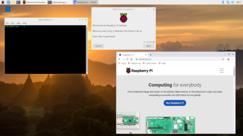
We are releasing a 'legacy' version of the Raspberry Pi OS based on Debian Buster, to provide a continuity option for users who require it.
 hushed vortex
ruby night
<@!478616919721771019> FYI -- with new support for the legacy camera < https://w...
hushed vortex
ruby night
<@!478616919721771019> FYI -- with new support for the legacy camera < https://w...
Awesome. I saw something about them adding camera support back in yesterday and was going to check it out.
pale pewter
Just to give you some context, here's my dev assembly. The Arduino is no longer connected. The single pixel you see is in the process of scrolling across all 8 8x8s. The goal here is a "message scroller" device. I was in the process of getting it to display text when today's problems arose. More to come...
 pliant pebble
ruby night
<@!478616919721771019> FYI -- with new support for the legacy camera < https://w...
pliant pebble
ruby night
<@!478616919721771019> FYI -- with new support for the legacy camera < https://w...
However, wouldn't it be a good idea to rewrite the code to account for future support issues??
hushed vortex
pliant pebble
However, wouldn't it be a good idea to rewrite the code to account for future su...
Yes. Ideally it would be updated to use libcamera. However, that may not currently be supported. They may have just re-enabled backwards compatibility for now.
steady rose
@pale pewter are the headers soldered on? looks a little thin in the photos
ruby night
hushed vortex
Yes. Ideally it would be updated to use libcamera. However, that may not current...
There is still no python API for libcamera, as far as I am aware...
hushed vortex
ruby night
There is still no python API for libcamera, as far as I am aware...
Yeah, that's what I thought.
pale pewter
@steady rose Yes they're soldered. It was one of my early efforts, so it may benefit from me revisiting it.
steady rose
@pale pewter it could be. this ref may help:
https://learn.adafruit.com/adafruit-guide-excellent-soldering/common-problems

it looks like too much of the pad (copper ring on PCB) is still visible on a lot of the pins
would indicate an un-solder issue, i.e. needs a bit more solder
ruby night
@hushed vortex First snag with tensorflow on bullseye ```sudo apt-get install -y libatlas-base-dev libhdf5-dev libc-ares-dev libeigen3-dev build-essential libsdl-ttf2.0-0 python-pygame festival python3-h5py
Reading package lists... Done
Building dependency tree... Done
Reading state information... Done
Package python-pygame is not available, but is referred to by another package.
This may mean that the package is missing, has been obsoleted, or
is only available from another source
E: Package 'python-pygame' has no installation candidate```
hushed vortex
ruby night
<@!478616919721771019> First snag with tensorflow on bullseye ```sudo apt-get in...
Ok, we'll leave the guide with still recommending buster then.
ruby night
sounds good! It was worth a try...
From that article, looks like Buster will be supported for a few more years.
hushed vortex
That's good at least
ruby night
There is hope https://packages.debian.org/bullseye/python3-pygame I'll keep poking at it.
using python3-pygame gets it moving again
got as far as pip3 install ./tensorflow-2.3.1-cp37-none-linux_armv7l.whl ERROR: tensorflow-2.3.1-cp37-none-linux_armv7l.whl is not a supported wheel on this platform. may need to look at some updates .....
hushed vortex
Yeah, there's probably a newer version
pliant pebble
hushed vortex
Yes. Ideally it would be updated to use libcamera. However, that may not current...
Cool
pliant pebble
ruby night
From that article, looks like Buster will be supported for a few more years.
So is Buster a LTS release??
ruby night
pliant pebble
So is Buster a LTS release??
I’m not sure that is the right terms https://www.raspberrypi.com/news/new-old-functionality-with-raspberry-pi-os-legacy/ more information here
hushed vortex
It might be more like how Microsoft supports old versions of windows for a few years after a new version is released.
 past zinc
Does anyone know if you can set the brightness of a section of pixels instead of forcing an overall brightness?
I'm using the Neopixel python scripting on a raspberry pi
I only see brightness set when declaring the pixels alias
umbral sable
past zinc
Does anyone know if you can set the brightness of a section of pixels instead of...
I believe in such a case you'd just use proportionally changed RGB values for the pixels you want at a different brightness.
past zinc
What's the main detriment to having all pixels set to 1 brightness? is it a power draw limitation or could it cause damage to the pixels themselves?
umbral sable
I don't think there's any limitation to running everything at maximum brightness, assuming your power supply can handle it. The pixels should be designed for it.
past zinc
sweet, yeah it seems like I'm running about 504 pixels with 150 watt power supply so I should be good.
umbral sable
You probably already know, but when you have many pixels, it's good to inject power at multiple places via separate wiring, rather than having a long string of 500 in a row, etc.
past zinc
yeah, I was thinking about that. I do have a 2nd wire to inject more power, I just need to tap into the power leads. just doing testing right now to see if it's all going to at least do what I want
it's all running from the same power supply, I just have an unused 2nd lead right now
 white sigil
Hello, I am having issues with the 3.5 inch LCD backpack, I have gone through the easy-install script process several times. It works just fine when I configure it for the console but when I run the script again for desktop / fbcp it just displays a black screen after rebooting. Plugging HDMI in shows an image (at low resolution)
 marsh narwhal
How to run SPI?
civic rune
You may need to setup spi in raspi-config.
Go to the terminal and run raspi-config
Or possibly raspi config not sure
Then one of the options will have a sub option for initializing spi
teal laurel
teal laurel
Hey all! I’ve got a pi 400 arriving Friday and a cyberdeck hat and I’m pumped. I...
FYI I started with bullseye and had no issues with the existing Adafruit install scripts! The cyberdeck lives
turbid rivet
past zinc
What's the main detriment to having all pixels set to 1 brightness? is it a powe...
Heat generation? You should be aware of the fact that driving that much current will cause things to warm up, and have some airflow so things don’t get too hot over longer periods of time.
If they’re spaced out enough, it shouldn’t be too bad, but it’s a possible concern you should be on the lookout for when you test it.
marsh narwhal
civic rune
You may need to setup spi in raspi-config.
Oh, i have rpi pico on mind
civic rune
Hmm I don't own one of those so I can't help unfortunately
It'll help if you're more specific with your issue. Your initial message wasn't verbose enough for specific help :)
 faint sparrow
Anybody available to chat?
i wanted to know, How can i run an application like "Image Viewer", "VLC", "Chromium" or any other application from raspberry pi terminal?
Nevermind
Now i want to know how can i close the application from the terminal
civic rune
hardy plaza
Just search "vlc command line". There is a wiki.
faint sparrow
civic rune
Possibly relevant https://forums.raspberrypi.com/viewtopic.php?t=179880#:~:text=...
Yup, Pkill is the command I used to close an application, Thank you
civic rune
Sure thing
faint sparrow
Do you know how can i open and close an application using python? i tried some the OS.system and Subprocess libraries but once the application is opened using thos methods, The python scripts doesn't move forward, it keeps waiting untill the application get's closed
So for example,
by using the OS library
os.system("onboard")```
*onboard is the application name i want to run@faint sparrow, there's also the --play-and-exit argument, which is probably a lot easier.
faint sparrow
faint sparrow
So for example,
by using the OS library
```import os
os.system("onboard")```
*o...
it does opens up the application but stop s the execution of the rest of the statements
faint sparrow
hardy plaza
<@456226577798135808>, there's also the `--play-and-exit` argument, which is pr...
Ummm, How do i use that in python?
hardy plaza
Whatever you're using to open vlc from the command line, you just add that argument.
E.g.,
os.system('vlc --play-and-exit ...')
error: no such options
hardy plaza
faint sparrow
as i've mentioned the application i want to open is the onboard
which is the virtual on screen Keyboard
i just mentioned VLC just to give an example of the default applications comes with raspberry pi
hardy plaza
Oh, sorry, in your original message you'd mentioned vlc.
hardy plaza
I'm not familiar with onboard. https://www.cyberciti.biz/faq/how-to-return-pid-of-a-last-command-in-linux-unix/
You need the PID of the onboard command in order to kill it. Using pkill is not really the proper way to do it, as you may end up killing things you shouldn't. Generally speaking you want to just kill the specific process.
All of this kind of thing can be done via os.system in python or via other python libraries that interact with Linux.
faint sparrow
pkill -x onboard
hardy plaza
Yeah, that works but is not a good practice. Like if you do pkill -x python you could have massive side effects.
faint sparrow
but i won't do that
hardy plaza
But I'm not here to lecture you on good practice, really.
faint sparrow
you know what, executing any command on terminal can have massive side effect like if you do sudo reboot
it can actually reboot the pi
wow
Dangerous isn't it?
hardy plaza
Yes, of course. You can delete your entire OS. You can shoot yourself in the head. We don't generally do these things.
faint sparrow
That's why we should not use Terminal
hardy plaza
No, that's why we should understand the commands available in Terminal.
faint sparrow
Yeah so that's why when we use pkill -x onboard it only kills the onboard and it's subprocesses not python
hardy plaza
I've been predominantly a command line user for over 30 years. (And I don't wear suspenders or have a pocket protector.) The command line is very powerful and there are a lot of tools available that work very well on the command line. The more you know the more functionality you gain. A windowing environment is by comparison very limited.
faint sparrow
So Anyway my real question was ...
hardy plaza
Yes, that is correct. I'm just trying to say that the general way to do that is to obtain the actual PID number and use that to kill the process. It's a good skill to have and to know how to do. Part of using a computer over time is to gain skills one doesn't already have.
faint sparrow
hardy plaza
Yes, that is correct. I'm just trying to say that the general way to do that is ...
Okay.......... Thank you for your advice, You are a command line user for over 30 years, So you probably are giving a good advice but i don't think you are getting my problem
hardy plaza
faint sparrow
Okay.......... Thank you for your advice, You are a command line user for over 3...
As I said, I don't have any experience with onboard.
faint sparrow
okay, forget about the onboard, Let's take any other application, chromium?
file explorer? ..... THonny?
hardy plaza
What are you actually trying to do?
hardy plaza
In order to find the process you need the PID. That's what the link I provided told how to do.
faint sparrow
civic rune
Look at subprocess
yeah, so i did had a look at the subprocess but it is also working same as the os.system()
hardy plaza
The process ID is what gives you a hook into the process you just started.
faint sparrow
let me share the link
civic rune
Does a program always have the same process id?
hardy plaza
No, it's basically randomly generated.
faint sparrow
@hardy plaza I think you are over complicating things
process = subprocess.Popen(['oboard'],
                     stdout=subprocess.PIPE,
                     stderr=subprocess.PIPE)
stdout, stderr = process.communicate()```So basically this is the script i run
and it opens up the onboard application
but the problem is
hardy plaza
I've got to leave now, but I suggest reading the os.system documentation: https://docs.python.org/3/library/os.html?highlight=os system#os.system
This provides how os.system and subprocess (and all the rest of Python) operates.
You can use stdout and stderr values to provide the returned content of your command. If you use that and the link I provided you earlier to get the process ID (PID) you can then have a hook into the process and/or subprocess.
faint sparrow
process = subprocess.Popen(['echo', 'More output'],
                     stdout=subprocess.PIPE,
                     stderr=subprocess.PIPE)
stdout, stderr = process.communicate() # script get's stuck at this line untill the onboard application is closed

print("Ended")```
The string get's printed out after the onboard has been closed not immediately after it opens up the onboard application@civic rune
civic rune
hardy plaza
I've got to leave now, but I suggest reading the os.system documentation: https:...
Nice link thanks
faint sparrow
If i never close the application, the string will never get printed out
hardy plaza
faint sparrow
```import subprocess
process = subprocess.Popen(['echo', 'More output'],
...
That is the correct behaviour of subprocess. I suggest reading the documentation to find out how to handle it properly. It basically waits until the process is complete before returning. https://docs.python.org/3/library/subprocess.html?highlight=subprocess#module-subprocess
faint sparrow
i have to manually close the application using the close button on the app
hardy plaza
Like I said, I don't know onboard. There may be command line arguments like in vlc to close upon completion. But I gotta run now, bye.
You can also add a "&" at the end of the command line to automatically background the process. Again, in the link I sent.
faint sparrow
Okay i found the solution to my simple problem to which these guys were complicating, AnyWay if anybody else looking for the solution it was just to use the Popen method instead of all that crap
so var1 = subprocess.Popen('onboard')
and then to close that application simply use
var1.terminate() Or you can also use pkill
pale pewter
ruby night
this may help <https://github.com/adafruit/Adafruit_CircuitPython_HT16K33/blob/m...
FYI, I finally got my development rig working stable enough to determine that the framerbuf stuff you pointed me to, IS what I needed. Thanks.
ruby night
pale pewter
FYI, I finally got my development rig working stable enough to determine that th...
Great! Glad it is working for you!
pale pewter
Well... I only have 2 out of 8 of my 8x8 matrices up and running, and I'm already seeing the performance price I'm paying by going to Python, from my earlier build's compiled Arduino code. #itsALearningExperience 😉
 agile depot
Is there a good 3D scanner compatible with the Raspberry Pi that uses something similar to Intel Realsense or LiDAR instead of just an RGB camera?
Preferably under $150 (Judging by the Intel prices, I dont even know if thats possible)
umbral sable
agile depot
Preferably under $150 (Judging by the Intel prices, I dont even know if thats po...
Maybe something based on hacking a Kinect?
agile depot
While I have a Kinect 360 I dont know if that would work since it requires 12 volts and a special adapter
Its also somewhat bulky to carry
pliant pebble
ruby night
I’m not sure that is the right terms <https://www.raspberrypi.com/news/new-old-f...
Hmm
So a Legacy release rather than Ubuntu's style LTS releases
 potent hedge
Mainly for people who were dependent on the stuff that was deprecated out of bullseye
I guess there were way more of those than anticipated
faint sparrow
Hi @hardy plaza @civic rune I apologize if my last message was disrespectful to you guys. There is a strong reason why my behavior was like that But I will leave that explanation To some time Later
they were just trying to make you follow best practices rather than close an app in a gung-ho way...
civic rune
Not to worry on my end. I appreciate the apology, shows maturity. Stress does unfortunate things to us.
hardy plaza
faint sparrow
Hi <@!828135237744984114> <@!887510739462537236> I apologize if my last message...
No worries, it's always appreciated when someone has the dignity to apologise. I hope you get it sorted. 😄
ruby night
pale pewter
Well... I only have 2 out of 8 of my 8x8 matrices up and running, and I'm alread...
Yes -- execution speed is not CircuitPythons strong suit.... development speed is another matter.
pale pewter
Aha! (While there's no question that Python is slower than a compiled language...) I figured out what the bottleneck was that was making my display animation flickery and slow. Now it's both smoother, and better fps. Woo hoo! (My apologies, but I had to crow.)
civic rune
Nice work!
 echo hare
hello everyone,
I have a raspberry pi 4 , hx711 and loadcell 5 kg . How can ı work it? I tried but ı didnt work
 lucid nebula
Hey, I got a question. Could I repurpose an old laptop, format the drive and install RaspberryOS onto it?
civic rune
I don't know for a certainty but my intuition says no
you could probably apply a regular linux distribution
wheat rain
hardy plaza
lucid nebula
Hey, I got a question. Could I repurpose an old laptop, format the drive and ins...
The answer you’ve heard is correct, no. But you can install a Linux distribution like Ubuntu with the LXDE window manager and you’d have basically the same desktop experience.
 hybrid heath
Is there any advantage to using a Raspberry Pi Camera Module 2 over a USB webcam on an RPi 4?
lucid nebula
wheat rain
Try this <https://www.raspberrypi.com/software/raspberry-pi-desktop/>.
Can you DM this to me, please?
 vocal otter
Anyone know how I can find out if a Broadcom Touch IC is compatible with a Pi?
hardy plaza
hybrid heath
Is there any advantage to using a Raspberry Pi Camera Module 2 over a USB webcam...
Advantage? That would depend entirely on what you want to do with it. If you want direct software access to a camera that you can wildly configure, post-process, gain access to individual pixels, etc. then the Pi camera provides that. And because it's not a USB device and its support is built into the OS you get some performance benefits as well (especially on Pis that don't have USB-C support). The Pi camera works out of the box via configuration (raspi-config), whereas with a USB camera you'll be relying on webcam support in Linux (like the Cheese or VLC apps). They're apples and oranges really.
Here's an example of some post-processing of the Pi camera I did on one of my robots:
Cheap Blob Detection
5 Oct 2020, NZPRG Wiki
https://robots.org.nz/2020/10/05/cheap-blob-detection/
west sierra
What's the most robust way of powering a Raspberry Pi Zero W via battery? I was hoping there was something I could use to be able to utilize something like this guy: https://www.adafruit.com/product/354

Need a big battery for your project? This lithium-ion pack is made of 2 balanced 2200mAh cells for a total of 4400mA capacity! The cells are connected in parallel and spot-welded to a ...
One of these, maybe? https://www.adafruit.com/product/2465

PowerBoost 1000C is the perfect power supply for your portable project! With a built-in load-sharing battery charger circuit, you'll be able to keep your power-hungry project ...
civic rune
west sierra
What's the most robust way of powering a Raspberry Pi Zero W via battery? I was ...
I don't think 3.7V is enough for the pi. It complains if I give it 5V instead of 5.1
west sierra
ohhh
2A internal switch (~2.5A peak limiting) means you can get 1000mA+ from a 3.7V LiPoly/LiIon battery. Just make sure your battery can handle it!
civic rune

A large-sized rechargeable battery pack for your Raspberry Pi (or Arduino, or Propeller, or anything else that uses 5V!). This pack is intended for providing a lot of power to an GPS, cell ...
hardy plaza
I'd probably use something like this, as you can (with a multimeter) tune it to 5.1v:
https://www.pololu.com/product/791
...and if you need 5A rather than 2A, there's this model:
https://www.pololu.com/product/2570

This powerful, adjustable boost regulator can generate an output voltage as high as 9.5 V from an input voltage as low as 1.5 V, all in a compact, 0.42″ x 0.88″ x 0.23″ package. A trimmer potentiometer lets you set the boost regulator’s output voltage to a value between 2.5 and 9.5 V.

This powerful boost regulator efficiently boosts input voltages as low as 2.9 V to a higher, adjustable output voltage between 4 V and 12 V while allowing an input current as high as 5 A.
west sierra
I want to put it all in the same case, though
west sierra
yeah, I am trying to figure out...
To make this even more useful, we stuck a smart load-sharing Lipoly charger on the other side. The charger circuitry is powered from a microUSB jack, and will recharge any 3.7V/4.2V LiIon or LiPoly battery at 1000mA max rate.
I believe this can be used with one of the 3.7/4.2V batteries, and output 5.2V
2A internal switch (~2.5A peak limiting) means you can get 1000mA+ from a 3.7V LiPoly/LiIon battery. Just make sure your battery can handle it!
@civic rune we can't read, neither one of us... like top paragraph:
This little DC/DC boost converter module can be powered by any 3.7V LiIon/LiPoly battery, and convert the battery output to 5.2V DC for running your 5V projects.
LOL
west sierra
me too
so I am thinking.... get one of the 18650 packs, either the double or triple, and it'll power that pi ZW for a hot minute
hardy plaza
I've been using the sister to that one:
https://www.adafruit.com/product/2030
on one of my Pi Zero powered robots, seems to work just fine.

PowerBoost is the perfect power supply for your power-hungry portable project! This little DC/DC boost converter module can run from 1.8V batteries or higher, and convert that voltage to ...
I was powering it from six AA cells (three in parallel).
west sierra
The Raspberry Pi Zero W draws around 260mA at idle and 370mA when stressed using Stressberry.
Found on https://www.tomshardware.com/reviews/raspberry-pi-zero-2-w-review
hardy plaza
west sierra
> The Raspberry Pi Zero W draws around 260mA at idle and 370mA when stressed usi...
Noting that you've provided a link to the newer Pi Zero W 2, not the original Pi Zero W.
west sierra
yeah
and I think I can use either one of these two:
https://www.adafruit.com/product/353
https://www.adafruit.com/product/354
Because they say to keep long-term draw under 1A.

Need a massive battery for your project? This lithium-ion pack is made of 3 balanced 2200mAh cells for a total of 6600mA capacity! The cells are connected in parallel and spot-welded to a ...
Need a big battery for your project? This lithium-ion pack is made of 2 balanced 2200mAh cells for a total of 4400mA capacity! The cells are connected in parallel and spot-welded to a ...
this is going to be awesome
hardy plaza
So one of those battery packs and one of the PowerBoost 1000s?
civic rune
Oh tiredness got me again, I thought you were using another pi. The pi zero 2 is not something I've used yet. I own one but too busy
hardy plaza
civic rune
Oh tiredness got me again, I thought you were using another pi. The pi zero 2 is...
Not hugely different, four cores vs. one on the original Pi Zero. But for those of us where an extra core or three is helpful (e.g.,Python concurrent programming), this makes the Pi Zero W 2 a very powerful small SBC.
hardy plaza
civic rune
I need to get into concurrent programming. What's an "easy" task to tackle?
Are you talking python or c++ or Java or?
civic rune
Let's say Python to start.
hardy plaza
There are three concurrent approaches in Python: threading, multiprocessing, and asyncio. They each have their reasons for existing and use cases.
civic rune
Hmm ok I'm planning on learning Asyncio for cp so maybe that will he a good jumping off point to desktop Python
hardy plaza
Python can't do "real" concurrent programming (like Java) because of the GIL, so which you choose depends on what you're trying to accomplish.
west sierra
So, I broke the little black thing on the camera connector on my RP ZW. What do I do?
 hardy plaza
Asyncio is more mature in MicroPython but one chooses one's own poison, so to speak.
civic rune
Yeah I mean to get back to uPy but the community here is so great I stick around
hardy plaza
I'd search around for a comparison of the three approaches because they're all valuable, and different.
hardy plaza
Asyncio is actually quite difficult to get right, in my experience.
Very tricky stuff.
civic rune
Interesting. In college for uPy we had a tasking suite that the prof wrote. I'll see if I can find out what he used.
hardy plaza
Here's a MessageBus class I wrote and am currently using on my robots: https://github.com/ifurusato/kros-core/blob/main/core/message_bus.py

GitHub
KROS Core provides the core functionality of a K-Series Robot Operating System (KROS), a Raspberry Pi based robot written in Python 3. - kros-core/message_bus.py at main · ifurusato/kros-core
You'd probably need to peruse the Publisher and Subscriber classes to understand the MessageBus:
https://github.com/ifurusato/kros-core/blob/main/core/subscriber.py
https://github.com/ifurusato/kros-core/blob/main/core/publisher.py
GitHub
KROS Core provides the core functionality of a K-Series Robot Operating System (KROS), a Raspberry Pi based robot written in Python 3. - kros-core/subscriber.py at main · ifurusato/kros-core
GitHub
KROS Core provides the core functionality of a K-Series Robot Operating System (KROS), a Raspberry Pi based robot written in Python 3. - kros-core/publisher.py at main · ifurusato/kros-core
civic rune
Cool thanks
west sierra
alright, ordered that booster and a 6600mAh 3-cell 18650 pack.
ruby night
west sierra
So, I broke the little black thing on the camera connector on my RP ZW. What do ...
I have usually been able to wedge them back in enough to hold. That is just place it in position with the cable inserted, then slide it in for a "friction fit"
faint sparrow
Does anybody here know any python module that can help me in Connecting Raspberry Pi to a WiFi network?
i can use the os.system to execute the commands in the shell to list and connect to the network but, firstly, I want it to be cross-platform (windows + Raspberry Pi OS) Secondly, it is a bit pain in the rear end to manually parse each network name or manipulate the entire command when you are getting inputs and giving outputs to a GUI, So i want a python module that can help me do that, So far i've tried the pywifi module which just doesn't work right for me
turbid rivet
Debugging? Are you suspecting hardware issues, or are you just trying to understand the inner workings?
For me, the REPL over USB is typically sufficient enough, but I have an extra Pico on the side if I ever need to build an SWD debugger for weirder issues.
If I want to observe a certain set of pins, I have a multimeter for measuring voltages and passive circuitry, and a USB oscilloscope for visualizing and measuring changing logic signals and the ocasional power noise.
 peak edge
I am doing my research at the moment. I want to develop a device and if need be
run a debugging session
i read that you can debug with another Pico
there is the jtag Olimex board
i was thinking of Particle Debugger with openocd
if some one have already done it
i have also read that the guys at raspberry use jlink by segger
but they are hella expensive
so yeah
asking does not hurt
pale pewter
Can someone please point me to the spec that tells me how many amps/watts I can expect to get out of the 3v3 pin on this RPi Zero W?
peak edge
this is the zero dc-dc converter
"Output Current: Up to 1A per Channel "
1 amp - (py zero power consumption)
 smoky magnet
Hi 👋 new to group…and hoping someone can help me? I’m having some issues getting an adafruit st7735 128x128 tft working on a raspberry pi. I hope I’m in the right section I’ve followed the info and installed the correct decencies but everytime in run getting hello world or any other script I keep getting errors. Can anyone please help 🤦♀️🤣🤯
 solemn finch
go ahead and post a link to the tutorial you followed and a copy of the errors you are seeing

 smoky magnet
solemn finch
go ahead and post a link to the tutorial you followed and a copy of the errors y...
smoky magnet
solemn finch
go ahead and post a link to the tutorial you followed and a copy of the errors y...
Cheers fella here is the adafruit tutorial I followed and this particular code I’ve run just now and the error showing up


 steady rose
@smoky magnet where did that image_timed.py example come from?
 hoary turtle
How much Ram is on the pi zero 2?
 hard pike
512MB
 heavy folio
does anyone have any resources for the pi400 keyboard shell as a 3d model?
 tidal crest
Hello,
which python modul would you recommend for creating a GUI for the raspberry Pi (Touchscreen 7 inch) with multiple pages (with dropdown menu, buttons, text, checkboxes etc.)
steady rose
try tkinter as a start, since it's the sort of standard
 half nexus
I need some help with WS2812B 8x8 hat matrix by waveshare, more importantly, running anything other than demos included. (I'm kinda newbie in this topic)
The pi is rpi 1 model b+ running stock raspbian
pale pewter
@half nexus Good morning! I've been working with a Pi Zero driving a chain of adafruit 8x8 matrices. Working in Python I'm using the adafruit_ht16k33 and adafruit_framebuf libraries. Not sure how similar that is to what you're doing, but if so, I'd be glad to help.
half nexus
pale pewter
<@!576427687132790794> Good morning! I've been working with a Pi Zero driving a ...
I'm a newbie here, and more likely to follow a set of instructions than get the direction of where it should go.
https://www.waveshare.com/wiki/RGB_LED_HAT_(B) I followed a bit on this wiki about this specific product that I have, and gained some superficial knowledge about running python scripts
Most of the code for these LEDs I found is for Arduino, which I don't have, which is why I'm using raspberry to drive this hat, which I can't find code to, because (loop basically)
pale pewter
@half nexus First, full disclosure: I'm not all that far ahead of you in this learning process, but I'm glad to share what (I think) I've learned.
To directly drive one of these LED matrices requires a fair amount of wiring and code. I've seen references to people who have done that, wiring the matrix directly to the dev board. I have not tried that. (although it sounds like an interesting challenge.)
What I've done is... Adafruit sells something called a "backpack" that does all the complicated electrical stuff, and lets you just connect two power wires, and two data wires, from the Pi to the display. You might want to look around and see if such a support board exists for that the matrix you're using.
half nexus
Well, I have what I have
Goal of this little project is to chose some Christmas pattern, and put it on repeat as a Christmas three decoration (I know, sounds wasteful)
If you want, I can start from scratch, or even try out some other libs
Just so it works
I don't have a time to play around with it, the deadline is slowly coming as the sun sets
pale pewter
Sounds like a perfectly nice project. Go for it.
pale pewter
I'll do some digging around and see if I can find reference to the "direct wiring" projects I mentioned. I'll post them here.
I suggest you post your progress, with some details, here. I, and I'm sure others here, will be happy to weigh in on how it's going.
half nexus
The hat works perfectly fine, I guess the only issue is just in software for it. Maybe we could make a Frankenstein out of two codes
 pale pewter
Is that lit up connected to a Pi? Or direct connect to power?
half nexus
Only to pins
I tested pi with desktop USB 2.0 output, and even strandtest.py for about an hour untill I bored
https://github.com/jgarff/rpi_ws281x here's the lib that drove mine, feel free to look into examples

GitHub
Userspace Raspberry Pi PWM library for WS281X LEDs - GitHub - jgarff/rpi_ws281x: Userspace Raspberry Pi PWM library for WS281X LEDs
LEDs got a little bit warm, but kept temperature consistent
pale pewter
One gotcha to watch out for is that the Pi's pins don't generally output enough power (aka amps/watts) to light up all 64 pixels at once. So trying to do so might cause problems.
I'll take a look at the repo. Have fun. Report your progress.
half nexus
I just recorded it in 60 fps, now I have to crop it
This server is boosted to max, so I have 100mb upload limit
In person it looks good and really bright, and hurts to look at directly
The power of LEDs is controlled in the script itself
turbid rivet
pale pewter
One gotcha to watch out for is that the Pi's pins don't generally output enough ...
For the Pi, 5V actually is regulated by the USB bus voltage, so there is no current limit set by the Pi. The limiting factor is only the power supply the Pi is connected to.
If your power supply provides a good enough current limit, there shouldn't be any problems there.
turbid rivet
500mA from USB might be a bit rough if you drive full white on all 64, but you should be able to drive about 40% brightness, which is more than enough for most color animations with non-white background.
half nexus
Well, this thing won't overcome a standard lightbulb, but surely it's brighter than my phone's flashlight
Well, like 64 times :P
turbid rivet
It should be plenty bright enough haha
half nexus
Well, I'm gonna use this indoors on a cloudy weather
So, what are the codes and libs that I can use with it, to achieve the goal, of making it into a Christmas tree decoration
LEDs won't be visible directly, so there's no point in shapes, pixel art or text on it
turbid rivet
I mean I wrote some minimal scripts in Arduino, so I can't say I have code on hand for the Pi.
What kind of visual effects are you trying to design?
Are you using Adafruit Blinka, or something else?
half nexus
half nexus
https://github.com/jgarff/rpi_ws281x here's the lib that drove mine, feel free t...
There's also a C# lib
I maybe can try out 500LEDs Xmas tree lib https://github.com/standupmaths/xmastree2020 it's fully on python, so why not
But I want to make it with some assistance

GitHub
My 500 LED xmas tree. Contribute to standupmaths/xmastree2020 development by creating an account on GitHub.
turbid rivet
It may be overkill for a single matrix, but it could be a good reference.
half nexus
I can try out and change quantity to 64
Well, any other code for the pi ¯_(ツ)_/¯
Well, you can suggest anything, if it would work, then it would work
half nexus
After not being able to run one of the examples, and idea came to my head to install every lib I know


Yeah
turbid rivet
Oh, the example requires a text file to contain the coordinates corresponding to the lights on the trees.
The instructions in the Github readme mentioned that.
half nexus
Yeah
turbid rivet
No library is going to account for that hahah
half nexus
But this idea struck me like a lightning that I was trying to run
half nexus
half nexus
https://www.waveshare.com/wiki/RGB_LED_HAT_(B) I followed a bit on this wiki abo...
I also tried bottle mentioned on the wiki before
Alright, one thing at a time
turbid rivet
https://learn.adafruit.com/adafruit-neopixel-uberguide/python-circuitpython should work, the matrix is just one 64-pixel strip arranged in a square.
that wiki would also work, though not sure how easy it would be to modify.
half nexus
I just want to run some exsisting code, which I currently can't find
turbid rivet
There is code at the bottom of the learn guide. It should work fine once you've set up CircuitPython. https://learn.adafruit.com/circuitpython-on-raspberrypi-linux/installing-circuitpython-on-raspberry-pi
half nexus

And some of my previous tries


While walking around the lib, I found file called ez_install.py
I ran it

 foggy onyx
Hi folks,
how this https://github.com/ChristopheJacquet/PiFmRds transmits radio waves using gpio ?? As raspberry pi gpio can only give output dc pwm, it cannot output ac and this program also works on dc pwm but radio waves work on ac, how this works how it is possible ??? Can anyone please tell me ??
Some vedios :-
English - https://youtu.be/4yhhW2ekgN8
Hindi - https://youtu.be/YcFn5oJbgi8
GitHub
FM-RDS transmitter using the Raspberry Pi's PWM. Contribute to ChristopheJacquet/PiFmRds development by creating an account on GitHub.

How to Hack FM Radio Frequencies with an RPi
Full Tutorial: https://nulb.app/z44hc
Subscribe to Null Byte: https://goo.gl/J6wEnH
Kody's Twitter: https://twitter.com/KodyKinzie
Cyber Weapons Lab, Episode 038
There's an entire spectrum of information that surrounds us. With a Raspberry Pi and some simple know-how, you can take social engineering...

In this tutorial I will show you that how to build FM radio transmitter using Raspberry Pi 3? how to make pirate radio station using RPi 3?
how to hijack FM radio stations using Raspberry pi?
Hardware:
RaspberryPi 3 B+ : https://amzn.to/2z3gzTp
SanDisk 32GB Class 10 with adapter: https://amzn.to/2AsRXoW
Software:
https://www.raspberrypi.org/do...
It really works man 🤯🤯
(I have tested it)
turbid rivet
foggy onyx
Hi folks,
how this https://github.com/ChristopheJacquet/PiFmRds transmits radio...
A digital output, in its simplest form, switches between high and low. It doesn't create the sinusoidal waves typical of regular radio waves, but it can certainly generate frequencies that can be picked up by an antenna tuned into the right frequency. The problem with this method is its harmonics, as square waves generate a LOT of harmonic frequencies, since its Fourier series equates it to a lot of higher-frequency sine waves. In most places, many of these frequencies are strictly regulated, so using this method to broadcast anything ove any significant distance could get you in trouble...
 turbid rivet
half nexus
What should I run on it?
turbid rivet
half nexus
What should I run on it?
sudo pip3 install adafruit-circuitpython-neopixel
Then run main.py.
half nexus
Lemme type in
It's collecting
failed with error code 1 in /TMP/pip-build-fxezsje7/sysv-ipc/
``` nah half nexus
Removing parts of code doesn't make sequences go away ¯_(ツ)_/¯
 turbid rivet
AH, @half nexus you need to be using python3. Python2 doesn't work.
At least not with the CircuitPython example? Probably most of them will have problems with the wrong version of Python.
half nexus
Ok ¯_(ツ)_/¯
Btw, any soft to work with iPhone?
When I used raspberry with Android, I just plugged it into available USB port, and turned on the USB hotspot on
Because my rpi doesn't have wireless support, it's much harder to do stuff on the go
Maybe I'll set one of the few examples to launch on boot. I couldn't find any pattern for it
half nexus
turbid rivet
AH, <@!576427687132790794> you need to be using python3. Python2 doesn't work.
So, I should type something like sudo python3 demo.py ?
I'll ask my teacher on the classroom hour to go to computer lab to configure this thing, and possibly pick something, or write something our own
half nexus
turbid rivet
AH, <@!576427687132790794> you need to be using python3. Python2 doesn't work.
It's working 👀
Such a beautiful animation, demo.py
This thing is sick

Ofc I'll come here again if I'll get any problems
civic rune
Is there any way to safely shut down a pi that you can't really physically get to and cannot ssh into?
umbral sable
civic rune
Is there any way to safely shut down a pi that you can't really physically get t...
Not really. Would you want anyone on the internet to be able to remotely shut down your computer without needing to touch it or log in to it?
civic rune
I didn't think so thanks
half nexus
Only power outage is the last answer
You have to touch the pi directly, or be a super user in order to do such critical stuff
hoary turtle
I just got my pi zero 2w. I tried to add the CLEAR case to it, but, it dosnt snap on. There’s a black small stub that’s sticking out on the back inside…. It seems to be stoping it
civic rune
I got one from them
pale pewter
I'm on the list to be notified. Waiting (mostly) patiently.
 rain timber
I use the sample code for (https://pypi.org/project/adafruit-circuitpython-bmp280/) to use my BMP280 with my Raspberry Pi zero W and i get this error ImportError: No module named adafruit_bmp280
However, I have installed the library by using pip install adafruit-circuitpython-bmp280 and pip3 install adafruit-circuitpython-bmp280
I2C is also enabled
I need altitude
civic rune
I don't think this is it, as I haven't needed sudo in the past, but perhaps sudo pip3 install...?
rain timber
Ill give that a shot!
Still didnt work,
Do i need that library for using the BMp280?
civic rune
Oh sorry the ...s were because I'm on mobile
It would be the full text of the call to pip3 with sudo before it
rain timber
nono i put all of that
civic rune
Hmm I'm not sure what's wrong. What you did should have worked
rain timber
Itsaid "requirementalready satisfied" andthen when running the code it said No module named adafruit_bmp280
civic rune
rain timber
nono i put all of that
Oh ok cool. Yeah still not sure what's wrong
foggy onyx
turbid rivet
A digital output, in its simplest form, switches between high and low. It doesn'...
Harmonic frequencies mean ??
foggy onyx
civic rune
https://www.dranetz.com/wp-content/uploads/2014/02/harmonics-understanding-thefa...
Ohhh, harmonic frequencies mean multiples of a frequency
hoary turtle
When you “cluster” Pi Zeros together, does that add up the RAM?
 opaque wagon
No
You need a special program to distribute tasks to all of them and then collect the results
And most programs don't support something like that
 rich vale
Hey, peeps, I have a question related to Image Processing. which camera is used to get a sense of an object (by Computer Vision) either by video processing or image processing because we are building a semi-autonomous bot to detect weeding to spray precision pesticides(only required amount of chemical to overcome bunch amount of chemical wastage as well to move small cultivation forward from blanket spraying to precision spraying)
umbral sable
rich vale
Hey, peeps, I have a question related to Image Processing. which camera is used ...
Generally that sort of processing is not done in the camera itself, but by software on a computer reading the images from essentially any camera. Depending on your needs, the camera might benefit from having the ability to record depth, polarization, or hyperspectral data instead of just regular color images, though.
 rancid pecan
i'm curious to learn the pros/cons of using circuitpython vs ardino for the MacroPad RP2040. Any thoughts?
umbral sable
rancid pecan
i'm curious to learn the pros/cons of using circuitpython vs ardino for the Macr...
Generally it's a tradeoff in ease of use versus performance. Python is friendly but slow and resource-heavy, whereas C++ is complicated but fast. To some extent it'll also depend on whether you need certain libraries for external devices that only are available in one language or another.
rancid pecan
I'm building the macropad to be an interface with VoiceAttack software (macro and voice control for apps/games). I've figured out how to do various key settings/combinations in QMK previously, but the echelon functionality will be to enable two-way comms between the RP2040 and a C# app (VoiceAttack) on the host PC.
 shut fog
Which pin is Board.D18?
rancid pecan
And QMK is C++ based so i have some familiarity there. But python seems very good to know these days
rich vale
umbral sable
Generally that sort of processing is not done in the camera itself, but by softw...
Umm
rich vale
umbral sable
Generally that sort of processing is not done in the camera itself, but by softw...
But we need to look for the variance of cameras
umbral sable
rich vale
But we need to look for the variance of cameras
I don't quite understand this sentence. Can you rephrase?
rich vale
There are varieties of cameras available which suits for our project I mean there's is a computer vision equip with pre processing (IP techniques) so which one is best
turbid rivet
rich vale
There are varieties of cameras available which suits for our project I mean ther...
I think you're going to have to provide more context here. There are a variety of edge-computing boards that can do some basic image processing, but I've never heard of a camera that does this.
rich vale

This article was originally published at Basler's website. It is reprinted here with the permission of Basler. Lost in the Jungle of Options? Faced
rich vale
turbid rivet
I think you're going to have to provide more context here. There are a variety o...
Could u plz take a look
turbid rivet
Well, I don't have any experience with imaging droplets outside, so I don't know how much my opinion would be.
You might have to just pick a camera and see how well it works...
rich vale
Umm
turbid rivet
rich vale
Umm
If you're really unsure, take a picture of your weeds and your spray and see if your resulting images are processable with your software.
If the image quality is insufficient, you can use that as a basis to gauge what your camera needs would be.
umbral sable
If you start with a clear, high-res image, you can down-res or blur it after the fact to see how bad of a quality you can live with.
turbid rivet
The weed detection might be super tolerant of any cheap image sensor, but I imagine properly imaging the spraying of pesticides will take a lot more experimentation.
rich vale
turbid rivet
The weed detection might be super tolerant of any cheap image sensor, but I imag...
Yea
turbid rivet
Unless I'm misunderstanding the purpose of the computer vision, and you don't need the spray visualized at all...
As someone who deals with 3d printing of wax models, I know there are other ways of controlling fluid output, though precision does vary based on the dispensing solution.
umbral sable
(Amusingly, now I'm imagining that over time, this sort of device would cause weeds to evolve to mimic the appearance of legitimate crops, specifically to fool computer-vision algorithms.)
turbid rivet
umbral sable
(Amusingly, now I'm imagining that over time, this sort of device would cause we...
But only if this technology becomes widespread enough to actually stick around for enough generations of selective weeding heh
@unique tulip are you proud of me
 unique tulip
turbid rivet
<@!214758164099366912> are you proud of me
unique tulip
turbid rivet
<@!214758164099366912> are you proud of me

I am simultaneously excited about the prospect of mechanical weeding and plant care but, at the same time, I've seen enough saucy Dr. Sarah Taber tweets retweeted into my feed on the subject of automating farming and doing it wrong.
rich vale
Umm ya tell me abt that concept dude if u know something that would help us
unique tulip
So, this was one of the twitter threads: https://twitter.com/sarahtaber_bww/status/1171895657872941056

Ok kiddos let's do this. Time to talk about my pretty-minimal-but-still-REALLY-WEIRD brushes with the MIT Media Lab.
Retweets
1694
Likes
3474
 Twitter
·
Twitter
·
OTOH, doin' it for funses is absolutely different from being an MIT Media Lab startup thing that failed to build the sort of growth chamber that mainstream science has been building quite successfully since 2001.
Citizen science is great.
Also, there's this: https://carbonrobotics.com/

Carbon Robotics
The Carbon Robotics LaserWeeder solves one of agriculture's biggest problems: weed control. Laserweeding kills weeds without herbicides or tilling by harnessing computer vision and thermal energy to identify and destroy weeds at the meristem. It's healthier for crops and land, and safer for farmers.
But, like, I don't think that solves everything, which makes a precision sprayer useful. Because, like, crusty bits on a leaf can be zapped on a laser, but it might be overall better to apply small amounts of chemical.
Also, it's very likely the case that you want hyperspectral imagery. It's REALLY easy to pick out living plant things if you are looking at the near-IR band that normal cameras reject.
civic rune
shut fog
Which pin is Board.D18?
Checkout pinout.xyz
rich vale
unique tulip
Also, it's very likely the case that you want hyperspectral imagery. It's REALL...
Thanks a bunch seems ur information would help someday in the process..
rich vale
unique tulip
Also, there's this: https://carbonrobotics.com/
This is so vast do u think can we ppl implement this in 8 months yes?
umbral sable
rich vale
This is so vast do u think can we ppl implement this in 8 months yes?
That just depends on who "we" is, heh heh. It's a project that's been done before, so it's clearly possible, but nobody here knows how skilled your team is.
rain timber
Using the sample code for circuit python Bmp280, i get this error
i2c = board.I2C()   # uses board.SCL and board.SDA
AttributeError: module 'board' has no attribute 'I2C'
Which board are you using?
rain timber
RPI zero w
 ripe pike
rain timber
Using the sample code for circuit python Bmp280, i get this error
```py
i2c = bo...
ripe pike
rain timber
Using the sample code for circuit python Bmp280, i get this error
```py
i2c = bo...
Can you post the python code that's causing this error?
rain timber
Im sorry i forgotto mention it, i reinstalled board and it works
half nexus
(dug up from general)
Hello there! Anyone know some sound/music visualiser for piromini unicorn hat/waveshare led hat(b)
 plush wave
Hi all just a quick one is there a way to turn off the mass storage on the pi pico
umbral sable
plush wave
Hi all just a quick one is there a way to turn off the mass storage on the pi pi...
Can you clarify what you're trying to do? The Pico runs code from the flash, so turning it off would generally be bad, unless you're very careful about transitioning to only RAM-resident code.
turbid rivet
plush wave
Hi all just a quick one is there a way to turn off the mass storage on the pi pi...
If you're talking about disabling the USB Mass Storage device on a Pi Pico in CircuitPython, try this guide: https://learn.adafruit.com/customizing-usb-devices-in-circuitpython

Adafruit Learning System
Hide CIRCUITPY or the REPL. Add another serial port or new HID devices.
plush wave
umbral sable
Can you clarify what you're trying to do? The Pico runs code from the flash, so ...
I've coded the pico to a hid keyboard and everything I plug it in it comes up mass storage
 humble marsh
plush wave
I've coded the pico to a hid keyboard and everything I plug it in it comes up ma...
humble marsh
plush wave
I've coded the pico to a hid keyboard and everything I plug it in it comes up ma...
they can't be printed, since there is no USB to print to
so they are put in that file
plush wave
humble marsh
make sure there is not a bug in your boot.py. Errors in boot.py will be reported...
So remove it if its there
humble marsh
what is in boot_out.txt?
if you want to disable CIRCUITPY, that is done in boot.py, as described in the guide above
that's also where you define new HID devices
and what is in your boot.py?
plush wave
Adafruit circuitpython 7.0.0 on 2021-09-20; raspberry pi pico with rp2040
Board ID: raspberry_pi_pico
I don't have a boot.py on the board
humble marsh
plush wave
I don't have a boot.py on the board
ok, that is why CIRCUITPY is showing up
 hard pine
can someone answer a quick question
from this page: https://www.adafruit.com/product/2345
Power protection circuitry - you can plug a 5V 4A wall adapter into the HAT and it will automatically protect against negative, over or under-voltages! Yay for no accidental destruction of your setup.
it also links to https://www.adafruit.com/product/1466 as the recommended power supply

You can now create a dazzling display with your Raspberry Pi Model Zero/A+/B+/Pi 2/3/ or Pi 4 with the Adafruit RGB Matrix HAT. This HAT plugs into your Pi and makes it super easy to control ...

Need a lot of 5V power? This switching supply gives a clean regulated 5V output at up to 4 Amps (4000mA). 110 or 240 input, so it works in any country. The plugs are "US 2-prong" ...
my question is this
do i need a switching power supply, or just any 5v 4a, or literally anything that can supply at least 5v 4a or more
how regulated does the actual power cable have to be
because it sounds like the HAT controls the voltage
asking because i really want to buy a cable without one of those boxes in the middle, i want to hang my project on the wall or put it on a high shelf
so i can't have a heavy weight in the middle of the power cable
if this https://www.amazon.com/MIXGOO-100V-240V-Switching-Transformer-Converter/dp/B08VWVLBWF/ works that's fine, but would be really great if i can also get a cable with a small plug as i have a lot of stuff plugged in near my desk

[UL Listed] MIXGOO 5V 4A Power Supply Charger (Input AC 100V-240V, Output DC 5 Volt 4 Amp 20 Watt) Adapter Switching Transformer Converter DC 5.5mm x 2.1mm / 5.5mm x 2.5mm Universal
https://www.amazon.com/3-Pack-2-1mm-Power-Barrel-Connector/dp/B07JGR7JJQ/ref=sr_1_8?keywords=DC+Cable+6ft&qid=1639166073&sr=8-8 could this work potentially

This cable is idea for small electronics and devices which use a 5.5mm x 2.1mm barrel jack for a power cable
could i just plug the USB end into the wall via an iphone brick or whatever
tldr i'm just wondering how much power regulation is needed in the cable
that last one basically does nothing and probably delivers the full 240v or whatever
right?
also lmk if there's a better place to ask about general electric stuff
turbid rivet
@hard pine Nobody really likes having to deal with wall warts on our outlets, or the annoying brick halfway up the power cable. The problem is that it's really rare to find a smaller USB brick that actually supplies more than 2.1A, and I personally wouldn't trust any number higher than 3.
Anything that could supply the 5V 4A would be fine, though the switching ones tend to be more power-efficient than the linear alternative.
Since the actual current is based on the load, any supply with a higher current rating is fine as well.
hard pine
thanks, so does the power regulation on the HAT protect against surges or actually reduce the current to 5v 4a
turbid rivet
No, it only protects against surges. There isn't any actual voltage regulation onboard, only overvoltage and undervoltage protection.
hard pine
kk
so i should just go for this https://www.amazon.com/MIXGOO-100V-240V-Switching-Transformer-Converter/dp/B08VWVLBWF/
[UL Listed] MIXGOO 5V 4A Power Supply Charger (Input AC 100V-240V, Output DC 5 Volt 4 Amp 20 Watt) Adapter Switching Transformer Converter DC 5.5mm x 2.1mm / 5.5mm x 2.5mm Universal
?
turbid rivet
If that works for your project, go for it.
It's easier to get AC extension cables if you really need the space, anyways.
The big bricks can be managed with a well-designed mount, if you can get creative in camoflauging it.
Wall warts are easier to manage, but can be frustrating when you run out of outlets...
hard pine
alright ty
pale pewter
Arghh. Yesterday afternoon I got the email that the Pi Zero 2 was back in stock. But it went into my spam folder (I don't know why, but I'm definitely fixing that), and by the time I discovered the email, the item is out of stock again. ☹️
 ripe berry
Don’t worry, I didn’t see it until about 1 hour later and they were all long gone by then! 😆
west sierra
I have a Raspberry Pi Zero W with an Adafruit Mini PiTFT - 135x240 on top. I am running a slightly modified version of the stats script from the https://learn.adafruit.com/adafruit-mini-pitft-135x240-color-tft-add-on-for-raspberry-pi/python-setup page, main difference is I am currently using sched to fire off events. Some to refresh the screen, and one to time out and kill the backlight to save power by not updating the screen until the button is pressed.
Are there any ways of using something similar to Alarm with a Raspberry Pi, where I can pause the script until the button is pressed? Or, does running a fairly tight 0.1s loop with a check to see if a button is pressed consume a lot of power? Goal is to power this entire rig with a battery.
This is the code mods I have done:
def show_stats():
    # the code from the regular stats example


def turn_off_display():
    backlight.value = False
    printing = False
    if not s.empty():
        for ev in s.queue:
            s.cancel(ev)


while True:
    if printing:
        s.run()
    if buttonB.value and not buttonA.value:
        printing = True
        backlight.value = True
        s.enter(0.1, 1, show_stats)
        s.enter(10, 1, turn_off_display)
        s.run()
    if buttonA.value and not buttonB.value:
        turn_off_display()
    if not buttonA.value and not buttonB.value and not printing:
        backlight.value = False
    time.sleep(0.1)
Maybe this should go in #help-with-circuitpython?
hardy plaza
west sierra
I have a Raspberry Pi Zero W with an Adafruit Mini PiTFT - 135x240 on top. I am ...
I don't use CircuitPython so I can't really provide help there, but in regular CPython or MicroPython there's the concurrency stack. I understand CP has now got asyncio.
In any case, whatever is your main loop will be running on a thread. You can either just loop that thread with a timer, or start a new Thread as a watcher. Or you could use the pigpio library to configure an interrupt on your event. There's lots of options. I'd probably use pigpio since you've got CPython on the Pi available to you. If you're not familiar with the library it's a good one to learn.
Raspberry Pi Reg. C GPIO library and Python GPIO module and shell command utilities to control the GPIO, including SPI, I2C, and serial links.
Specifically: http://abyz.me.uk/rpi/pigpio/python.html#callback
Raspberry Pi Reg. C GPIO library and Python GPIO module and shell command utilities to control the GPIO, including SPI, I2C, and serial links.
west sierra
oh cool, so I can run an interrupt with pigpio?
hardy plaza
Yes, you'd set a callback on either a rise, fall, or either, on a pin.
Having libraries like pigpio are one of the reasons I've so far tended to stick with the Pi rather than an MCU. I've tried porting a few of them to MicroPython and/or used the micropython-lib project's files as a basis.
west sierra
Dang! That's amazing.
west sierra
hardy plaza
Yes, you'd set a callback on either a rise, fall, or either, on a pin.
Also, I sort of glanced somewhere that there's a way to halt/poweroff the device and have it wake on GPIO, do you know if that's a thing, and if so, where I can read more about it?
hardy plaza
Yeah, that's a thing, hold on a minute... (I'm preparing for a flooded basement tonight)
BTW, you can also use the RPi.GPIO library's GPIO.wait_for_edge() method if you don't want to use pigpio. There's no callback and the code blocks until the pin transition occurs. So it's both simpler and less powerful.
Regarding the poweroff/wake on GPIO idea, the power down part isn't difficult, you just use whatever is your trigger (could be anything) and call:
import subprocess
subprocess.call(['shutdown', '-h', 'now'], shell=False)
The trickier part is the startup. In this case you'll have a powered-up and shut down Pi. The trick here is to use GPIO 3, which has its own special functionality. Here's a link: https://howchoo.com/g/mwnlytk3zmm/how-to-add-a-power-button-to-your-raspberry-pi

Howchoo
This guide will show you how to add a power button or switch to your Raspberry Pi that can turn your Pi on or off.
west sierra
can I not use another GPIO?

Adafruit Learning System
The most compact li'l color display for a Raspberry Pi
I have this guy, and those two buttons
top is for turning the screen on and output some stats for the wireless AP
which I've got working, mostly, but it could probably be better
and then I just have a timer that shuts the screen back off after ~10 seconds
hardy plaza
Not for wakeup, no. GPIO 3 is special.
hardy plaza
west sierra
https://learn.adafruit.com/adafruit-mini-pitft-135x240-color-tft-add-on-for-rasp...
yeah, I love that display, use it on my robots.

That's running 'top'
west sierra
hardy plaza
Not for wakeup, no. GPIO 3 is special.
do you think... with a https://www.adafruit.com/product/2223 I could access it?

Connect your own PCB to a Raspberry Pi B+ and stack on top with this normal-height female header with extra long pins. The female header part is about 8.5mm tall, good for small HATs ...
and of course it's like the one kind of header I don't have at hand
hardy plaza
What I've done is make up a Dupont connector wiring harness to bring the Pi's pins over to the display. I can't mount it on the Pi as the space isn't available and it'd not be viewable.
west sierra
makes sense, which parts did you use for the wiring harness?
hardy plaza
I bought a kit of assorted connectors from AliExpress, a bunch of single and double row Dupont (0.1") connectors. Some people use a crimp tool, and that's certainly easier, but I hand-solder all mine.

I was originally using "Jumper Jerky", the rainbow ribbon cable, and peeling off what I needed. That works, though the wire is a bit stiffer than I like and there's only two lengths available. It's more work but I started making up wiring harnesses for most everything on my robots. It takes a lot more time but I just try to get into my "Zen soldering mind". 😇
west sierra
I have a crimp tool, and a bunch of duponts floating about
hardy plaza
But the Jumper Jerky works fine in a pinch. There's also Adafruit's pre-made ones: https://www.adafruit.com/product/5070 if you only need a few. You can use a very sharp instrument to unlatch the pins from their sockets and push them into a different socket (e.g., take out the single row pins and push them into a double-row connector.
I would entirely avoid the Dupont male connectors, they're very weak and their little members break off pretty easily. Just use pins, double ended, when necessary.
west sierra
lemme see what kind of crap I've got
hardy plaza
west sierra
I have a crimp tool, and a bunch of duponts floating about
Ah, then you're most of the way there.
west sierra
(something off of Amazon)
hardy plaza
west sierra
lemme see what kind of crap I've got
I try never to ask that question myself...
west sierra
hahahaah
hardy plaza
I have a whole basement full of damp crap now.
west sierra
it's like, I have some legit great things in my lab, like from Adafruit and SparkFun and whatever, and then there's these kinds of things that are harder for me to find on a site like Mouser or Digi-Key. Still haven't figured out if I even can find the cheap stuff there, or if they only have the trademarked stuff.
Like. Dupont connectors. Entire cases full of 2.5M and 3M machine screws in varying length with socket cap hex heads and washers.
Bags full of nutserts.
You having a flood?
hardy plaza
Yeah, since last March the stream next to my house has been diverted (possibly by a tree root) under my foundation, or at least next to it, such that during heavy rains it's now flooding my basement, 20-30cm of water at times. This being New Zealand I can't get a plumber or drainlayer to do the work because they can't be bothered. I'm currently being ghosted by my 7th (attempted) plumber. 😑
As to DigiKey and Mouser, you can sort on price and find the cheaper items as well. I know you can buy a mil-spec subminiature toggle switch for $50, but you can also find the cheap ones for a few dollars. They're never be as cheap as AliExpress, but we all pay for that in different ways, so I tend to avoid AliExpress except for things like Dupont connectors. I once bought a torch/flashlight I'm happy with, and buying from the actual Chinese manufacturers of things like the Orange Pi is probably fine.
west sierra
I'll search for something like cat 6 cable, and get like $70/foot industrial indestructible shenanigans cable.
hardy plaza
Part of what is difficult for me now, is that the US Postal Service will no longer ship to New Zealand, so I had an order to buy a small number of parts from Adafruit but the DHL cost to ship it here is now NZ$64. So I basically have stopped buying from Adafruit, it's just too expensive to ship here. It's actually cheaper to buy Adafruit parts from Pimoroni and suck up the dollar-to-pound conversion that happens there, as I can get Royal Mail shipping for I think about £9.
west sierra
AliExpress is definitely a somewhat worse lottery than Amazon, unless you're buying components.
hardy plaza
west sierra
AliExpress is definitely a somewhat worse lottery than Amazon, unless you're buy...
But if you can find out the actual manufacturer and buy from them, it's not so much a gamble.
west sierra
hardy plaza
But if you can find out the actual manufacturer and buy from them, it's not so m...
exactly
but on Amazon you never know... they change names of these stores every few weeks/months, but it's probably the same factories producing the same stuff, and it's probably patent infringement and various other intellectual property laws they are breaking... but, they're in China, and what can you do?
Every now and then I get lucky with ordering electronics components off of Amazon, but, I've a few too many incidents so I just don't any more.
hardy plaza
What I can't figure out is the USPS won't ship to NZ because it's not profitable enough, yet much of what I can order on AliExpress ships here free. My understanding is that the Chinese government is basically subsidising Chinese businesses (who aren't themselves otherwise profitable) in order to out-compete Western businesses. It's not like that's unusual, the US government has had farm subsidies for decades. The difference here is that it's in technology now...
hardy plaza
west sierra
but on Amazon you never know... they change names of these stores every few week...
I've stopped doing business with Amazon entirely. Especially after Jeff Bezos made it clear I was financing his giant-ego-shaped rocket ship.
In any case, dinner time here! ciao!
west sierra
hardy plaza
What I can't figure out is the USPS won't ship to NZ because it's not profitable...
Yeah, for sure. I know China has a way bigger market share in Australia, for instance.
I was like trying to figure out if there was a way I could route packages for you through Sweden, but it's not cheap to send packages from there, either it appears. an up to 1 kg package costs ~$41 USD to send to a non European country.
(I'm from Sweden, and all my family is there, but I live in the US)
oh, that was the parcel service... I think if it's components from Adafruit, I can get them here to me for like $10-11 (sometimes cheaper with USPS), and then ... sending to Sweden is $69.95. No joke. Wow.
oh wait, no, $38.20 Sweden, and then from there like $20 to New Zealand. Still sucks. Wow.
 dusty wolf
Hello. My Wio Terminal has an accelerometer, but no LIS3DH library to connect it. Can I install it on the board, if so how?
west sierra
dusty wolf
Hello. My Wio Terminal has an accelerometer, but no LIS3DH library to connect it...
Please don't post in multiple channels.
 late kernel
Hey - I am using the adafruit 4x7 segment display with the backpack and am experiencing some prolems related to i2c on my raspberry pi.
(I am trying to follow this: https://learn.adafruit.com/adafruit-led-backpack/0-dot-56-seven-segment-backpack-circuitpython-and-python-usage)
- I know the problem isn't the display because it works fine with an arduino
- I can run commands like
i2cdetect,i2cget, andi2csetand they all work for my device - when I run the most basic setup in python:
>>> import board
>>> from adafruit_ht16k33.segments import Seg7x4
>>> i2c = board.I2C()
>>> display = Seg7x4(i2c)
That last line throws an error
Any help would be much appreciated
west sierra
hardy plaza
I don't use CircuitPython so I can't really provide help there, but in regular C...
My friend, this was an amazing solution! Script consumes virtually no CPU once it's started and running on a 60 second timer.
steady rose
@late kernel what address shows up in a scan?
https://learn.adafruit.com/scanning-i2c-addresses/raspberry-pi
late kernel
sudo i2cdetect -y 1
     0  1  2  3  4  5  6  7  8  9  a  b  c  d  e  f
00:          -- -- -- -- -- -- -- -- -- -- -- -- --
10: -- -- -- -- -- -- -- -- -- -- -- -- -- -- -- --
20: -- -- -- -- -- -- -- -- -- -- -- -- -- -- -- --
30: -- -- -- -- -- -- -- -- -- -- -- -- -- -- -- --
40: -- -- -- -- -- -- -- -- -- -- -- -- -- -- -- --
50: -- -- -- -- -- -- -- -- -- -- -- -- -- -- -- --
60: -- -- -- -- -- -- -- -- -- -- -- -- -- -- -- --
70: 70 -- -- -- -- -- -- --
(and as mentioned above I can get and set to that address)
steady rose
the remote io errors could mean a connection issue
something marginal, good enough for scan and one off xfers
but not heavier traffic of driver code
how is the backpack connected to the pi?
steady rose
headers are soldered on backpack?
late kernel
yeah
and they work with arduino
so the backpack should be good
i also tried another pi and the same error was thrown
steady rose
this backpack?
https://www.adafruit.com/product/878
late kernel
yep
steady rose
weird. can you post photo?
late kernel
 steady rose
thanks. one more of other side too if you can.
late kernel
 steady rose
could also be pi headers - is that a Zero WH? or did you solder headers on pi?
late kernel
i did those headers, but I tried it with a 400 and it threw the same error
steady rose
try reflowing those header pins and see if it helps

no more solder, just reheat with iron and make sure they are wetted out well on the pads
late kernel
even though it worked with an arduino uno?
steady rose
yah, that's weird, but could be 5V vs 3V got past whatever marginal issue there might be
late kernel
should i try 5v on the pi?
steady rose
nope. it should just work at 3v.
the behavior you are seeing + the current state of soldering = it's worth trying to reflow the soldering first to see if it helps
those four pins are all that are needed for talking to the backpack, the LED pins are just for lighting the LEDs, there's no i2c on those
photo here is a good ref:
https://learn.adafruit.com/adafruit-guide-excellent-soldering/common-problems
late kernel
@steady rose just reflowed - still not working
steady rose
same behavior?
steady rose
if it did same thing on a pi 400, then probably not
but still worth checking
it could be multiple things 😦
late kernel
still nothing
steady rose
nothing? or same behavior?
steady rose
can you try again on the pi 400?
steady rose
unfortunately it is most likely the soldering
but hopefully just reflowing will help
the amount of solder looks OK
but potentially not wetted out enough on pin and pad
key is to get both pin and pad adequately heated, so solder will flow on to both
plush wave
Quick question, is there a hid keyboard matrix coding out there.
Want it try a 45 key project with 1 board but some of the buttons need to have double key imputs
pale pewter
late kernel
Hey - I am using the adafruit 4x7 segment display with the backpack and am exper...
FWIW, In my project using the adafruit_ht16k33 module the i2c creation call is: i2c = busio.I2C(board.SCL, board.SDA) ??
late kernel
both work
civic rune
pale pewter
FWIW, In my project using the `adafruit_ht16k33` module the i2c creation call is...
board.I2C() is a helper function that does what you're doing explicitly to the pins board.SCL and board.SDA
pale pewter
civic rune
`board.I2C()` is a helper function that does what you're doing explicitly to the...
I wondered about that. Thanks.
civic rune
Sure thing. Your method seems to show up in older guides, I think because the helper function didn't exist.
smoky magnet
steady rose
<@!707293267540181084> where did that `image_timed.py` example come from?
Sorry for the delay
The example code is from a python bundle for the ST7735 screen I have
 lost stirrup
Hi does anyone have i2c example c language code for feather rp2040?
 marsh surge
Hello, first time posting here but I got myself into a little pickle i'm wondering if anyone can help me with... So I built a PiGRRL zero as a gift for a friend who is getting deported from Canada for bs reasons during christmas, so i decided to make him something. Long story short I thought I had another 2 weeks to work on this but because of immigration bs that time has evaporated and my last work day is tomorrow. So what I have right now is a fully functional PiGRRL zero with a raspberry pi zero W as a brain. This is the guide I was following and I had 0 problems with the hardware... all the problems came in the software. first I couldn't get emulators to show up with th e default OS posted (but i could run doom and the controls worked) then i realized the automatic method wasn't meant for pi zero W models so I tried manually installing the latest retropie. It runs fine but I couldn't get it to connect to wi-fi (despite seeing the networks) and I couldn't get the controls to work. I'm running out of time quick and at this rate the gift will be a doom exclusive machine. does anyone have any ideas on what to do now?
btw here is the project pictures atm


Today i'm spending most of my time finishing the case so i'm running out of time to spend sitting at a desk troubleshooting everything. The problem with the most recent retropie was the wi-fi trouble I had (and i got no errors just a couldn't connect to network) I have 0 idea how to properly add support for any of the hardware attached to the pie, and with the older version from adafruit with proper support already implemented for controls and screen support i couldn't get emulators to appear when I added roms. Because of this I feel really stuck, I don't have any more time to troubleshoot error after error which keeps happening, and i know the hardware is functioning perfectly. Does anyone have a pre-made OS or anything like in the comments that's up to date? I have full rom archives as my disposal and if i can just get past that dumb error i should be okay
civic rune
That's a very thoughtful gift. I can't offer any help but nice work.
 modern tundra
https://youtu.be/nXeKEEG_69M
hey guys i made a usefull video on how to get analog audio on the raspberry pi
In this video i will show you all how to get analog audio output on the raspberry pi zero and zero 2 W (it will actually work on any raspberry pi) using a small audio filter and some adjustments to the raspberry pi settings.
 subtle dust
Has anyone play with HID mouse emulation with raspberry pi zero ?
I would like to control my mouse with my raspberry pi zero
Things like https://davesteele.github.io/raspberrypi/2021/04/18/keyboard-jiggler/ but for mouse
opaque wagon
modern tundra
https://youtu.be/nXeKEEG_69M
hey guys i made a usefull video on how to get analo...
maybe #show-and-tell would be a better place - but looks cool!
 violet ivy
Hello, I'm trying to get a led strip (ws2801) working... but i can't control the led strip somehow.
I'm using a raspberry pi 4 with adafruit_ws2801 in python and the pins MOSI for data and SCLK for clock.
any ideas?
did you restart your pi? no, did you need to restart your pi? yes
fixed 😛
 torn mountain
Hi all, this is my first time working with a raspberry pi + neopixels, but im having a lot of trouble understanding what is going on. I have a 16 LED ring WS2812, and I've been trying to get them to work by following these instructions: https://learn.adafruit.com/neopixels-on-raspberry-pi/python-usage ( I did have an issue with the second command (sudo python3 -m pip install --force-reinstall adafruit-blinka) Everytime I tried to run this, I'd get an error when Building wheel for RPi.GPIO. Maybe this has to do with the stuff I'm seeing below?
I've been noticing weird interactions with my neopixel ring, when I plug it into different data pins, I get different interactions. With 18, I get only three LED's lighting up random colors, and flickering, when I try to fill with one color like (0, 50, 0).
on other pins, like 21 (which is working the best for me), only pixels 0-12 work, and they don't work correctly for the defined colors. for example, when I fill with (0,50,0), I expect to get all green, but I get alternating yellow, blue, red colors. each pixel interacts differently with each color, and I'm really confused as to what is going on 😦 Sorry for the huge block of text, I'm new to rasp pi, and this kind of tinkering, and I hope somebody can help, thanks. The attached image is running fill with green only (0,50,0) on pin 21. I also have two LED rings and they both share the same behavior, which makes me think its not a hardware issue.


Adafruit Learning System
How to control NeoPixel LEDs with Python on a Raspberry Pi!
some extra information: I am running this without any level shifting or diode, and only running it off the 5V pin on the pi, (not sure if its okay, but I've seen from googling that for a small number of LED's this shouldn't be an issue), pins 21 and 10 do the interaction where filling will create the alternating yellow, blue red. Pins 18 and 12 won't fill and show, I have to put the fill in a while True infinite loop for the lights to flicker, and only the first few lights flicker.
west sierra
Does anybody know if this is still an issue with the 400/Cyberdeck/Hyperpixel 4.0? https://forums.adafruit.com/viewtopic.php?f=50&t=179733&start=30
I purchased a Cyberdeck like a week or two ago, not sure if it's the same rev or not?
steady rose
@west sierra yep. the guide should have been updated with that info....but not seeing...checking why.
https://learn.adafruit.com/cyberdeck-bonnet-and-hat/overview
west sierra
steady rose
<@!438791522285256715> yep. the guide should have been updated with that info......
for some reason the Hyperpixel 4.0 guides are also no longer on the Learn site.
steady rose
which guides? the hyperpixel itself is a pimoroni product.
west sierra
There used to be a guide for how to hook it up.
used to be on the product page, but it's no longer there
you know what, I might be confused, because I am looking at the Wayback Machine from October and they're not there either. So, I just made that up. In my head. Like a crazy person. Move along.
steady rose
no worries. could be something related? like a project guide?
west sierra
Yeah, it was a project guide, but it wasn't the photo one or whatever.
steady rose
but in general, since it's a pimoroni product, best to go there for the details
west sierra
yeah, I usually do
@steady rose so does this mean I should be cutting the trace on my Cyberdeck?
steady rose
yep. the guide info is the same as that forum thread.
there are two options though
let me look at the thread again. the info in the thread is kind of scattered. the guide brings it all together.
meh, easier to just enliven the guide page
west sierra
one was desoldering
steady rose
west sierra
Thank you. Well, I gotta take Trace and Xacto to the doctor. Someone's getting snipped!
west sierra
@steady rose I shouldn't have cut that trace... now I've got a round, encroaching blackness coming in from the sides
steady rose
on the display?
west sierra
yup
I guess I just killed my Cyberdeck.

I just noticed, the STEMMA connectors are white on this image. They're black on mine.
Did I cut too deep, or not deep enough?
It shows the boot screen, but then it doesn't show the terminal window
steady rose
connector color doesn't matter. that's just a supplier variance.
doubt you cut too deep
do you have a multimeter? could use that to verify trace is cut.
west sierra
steady rose
do you have a multimeter? could use that to verify trace is cut.
Yes, I do have a multimeter. How do I verify?
Thank you for helping me with this. I would be super sad if I broke it right before Christmas.
steady rose
continuity test
between those two point

actually, measure resistance. since there's still that resistor in line.
hardy plaza
west sierra
Does anybody know if this is still an issue with the 400/Cyberdeck/Hyperpixel 4....
I can't speak to which version of the CyberDeck I have compared to yours, but I unsoldered the diode on mine to make it work. I know have it in a tiny ziplock bag in case I want to reattach it some day in the distant future...
west sierra
hardy plaza
I can't speak to which version of the CyberDeck I have compared to yours, but I ...
It's a good thing the decks aren't that expensive. I hope mine is fine. Did you see my ridic build to get the square HP4 on the 400?
hardy plaza
west sierra
It's a good thing the decks aren't that expensive. I hope mine is fine. Did you ...
No, but I can imagine. The HyperPixels are quite a nice display but as they use such an unusual method of gaining that performance (by using most of the GPIO pins) they leave the Pi kinda useless for anything else. I almost wish I could just get that same form factor (i.e., the hardware is excellent) and just use the HDMI instead.
turbid rivet
hardy plaza
No, but I can imagine. The HyperPixels are quite a nice display but as they use ...
I wouldn't call it unusual, since that type of display is actually fairly common. Instead of adding an expensive HDMI chip, products with built-in screens tend to use these DPI displays for reduced cost. Being able to drive a display with GPIO pins is nice, but if you can accept a slightly lower color count, there are ways to free up a few more pins by disabling the less significant bits.
It's probably also worth noting that most basic projects only use a few pins, and the more complex projects will offload some of the work to external GPIO expanders or other auxillary devices.
I can't speak for older Pis, but I know for a fact the pi4 can definitely support a DPI display and an I2C bus.
west sierra
hardy plaza
No, but I can imagine. The HyperPixels are quite a nice display but as they use ...
Yeah, I hear you. However, I am using this for a Pi 400. It's a very portable computer with a tiny screen, meant for coming with me in the field, and for connecting manually to routers/switches/firewalls to configure via Ethernet or Serial.
So, I am using this screen as the main display for the OS. I haven't fully settled on a wm yet, but still looking for something quick and easy, yet powerful.
Main issue is that these drivers really only work well for Raspbian. And Bullseye is out because of the changes to DPI drivers.
west sierra
hardy plaza
No, but I can imagine. The HyperPixels are quite a nice display but as they use ...
@turbid rivet this is what it ended up looking like. It's a Cyberdeck HAT with the Pimoroni HAT Hacker HAT.

 hardy plaza
west sierra
<@!98211350907490304> this is what it ended up looking like. It's a Cyberdeck HA...
hardy plaza
west sierra
<@!98211350907490304> this is what it ended up looking like. It's a Cyberdeck HA...
Yes, I have a similar arrangement using the rectangular HyperPixel and a Pi400. My only criticism of the Cyberdeck HAT is that I wish it was built on a hinge so that the actual display angle was modifiable, like on a laptop. Or make one specific to the Pi400, where the display could fold flat against the keyboard, making it a very tiny laptop...
west sierra
hardy plaza
Yes, I have a similar arrangement using the rectangular HyperPixel and a Pi400. ...
Sounds like you're volunteering to write a Learn article on how to do that. 😉 Hinges are hard, though, especially to get them to stay in a particular place, like a laptop lid.
 thin wraith
how would i use this
http://www.adafruit.com/product/1095#tutorials and http://www.adafruit.com/product/1096#tutorials that with a raspberry pi.
say i wanted to turn on an led with them what would the wiring and the code look like
This 4-button keyfob remote goes with our three basic 315MHz RF receiver modules. It will work with all of them, sending out one of four commands that match up with the four outputs. Its ...

These Simple RF receivers are the easiest way possible to add wireless control, painlessly! There's no programming, configuring or addressing - simply power the receiver with ~5 VDC and ...
west sierra
thin wraith
how would i use this
http://www.adafruit.com/product/1095#tutorials and http://w...
I would use CircuitPython on the Raspberry Pi and connect the M4 Receiver to the Pi's headers.
Adafruit Learning System
Make hardware and interface with sensors super easy using CircuitPython
Adafruit Learning System
Make hardware and interface with sensors super easy using CircuitPython
Then take a look at that article and it should get you in the right direction. Have you used Python before?
You can wire D0 through D3 on the receiver to basically any free digital pins on the Raspberry Pi.
thin wraith
west sierra
Then take a look at that article and it should get you in the right direction. H...
i have very limited experience but ill read the articles you sent me, tysm
west sierra
thin wraith
i have very limited experience but ill read the articles you sent me, tysm
Yeah! Feel free to ask in here about Raspberry Pi questions, but for the rest of this experiment, it's probably easiest if you direct the questions to #help-with-circuitpython. There's a bunch of us in there that can help you.
west sierra
thin wraith
i have very limited experience but ill read the articles you sent me, tysm
I would recommend using something like Poetry. It's probably easiest to get started with. That way you get an environment for just your project/experiment that you can easily delete later.
Python dependency management and packaging made easy
Basic usage For the basic usage introduction we will be installing pendulum, a datetime library. If you have not yet installed Poetry, refer to the Introduction chapter.
Project setup First, let’s create our new project, let’s call it poetry-demo:
poetry new poetry-demo This will create the poetry-demo directory with the following content:
poetr...
west sierra
thin wraith
thanks
any time... using something like poetry prevents a bunch of crap installed globally that might conflict with other things you write/run later on
turbid rivet
thin wraith
how would i use this
http://www.adafruit.com/product/1095#tutorials and http://w...
Wiring would be
Pi --------------- Receiver
5V --------------- 5V
GND -------------- GND
GPIO() ---[1kΩ]--- D()/Vt
Resistor value can be flexible, I don't think I know of an exact range but it does have to be there because of the voltage difference.
You can also use the onboard Python with a simple GPIO library like gpiozero for something simple like this. https://projects.raspberrypi.org/en/projects/physical-computing/0 provides a good overview, and the only difference between this receiver's code and the button code would be adding a false argument after the pin number when you declare a Button().
 vague bear
Hi Everyone - I've exhausted my stack-overflow search abilities. I'm a mac user so I've become accustomed to using defaults read and defaults write to store non-secure variables for scripts. Is there a way to do this in on rpi?
steady rose
scripts written in what?
 frosty kernel
I want to use a I2S module with my Adafruit Feather RP2040 but in the exemple that i saw, the GPIO18 is used but on the Feather it's used already used by a neopixel
steady rose
@frosty kernel is that a circuitpython question?
frosty kernel
steady rose
<@!590995193680101378> is that a circuitpython question?
no micropython
vague bear
steady rose
scripts written in what?
Generally Python3 (but also generic shell scripts)
steady rose
i think that defaults thing might be macos specific?
vague bear
ok. That's what I thought.
steady rose
and is for saving application configuration settings?
is that what you're trying to do? or is it some other variables?
vague bear
Yes. for app config - Open to suggestions 🙂
steady rose
sry. i don't have any. but that sort of thing tends to be OS specific.
if it's environment variables, there's os.environ
vague bear
Thanks @steady rose I appreciate the confirmation / info
steady rose
and also get/putenv (same page)
 grim geyser
Hey all
So I am in search of someone who knows Python
I have a CubeSat project on right now, and for that I require a person of this skill
If you know ANYONE such, pleaseeeee do inform me as soon as possible.
hardy plaza
grim geyser
Hey all
**So I am in search of someone who knows Python**
**I have a CubeSat p...
You should probably mention what you want this person to help you with, as just asking for a general skill is asking someone to commit to helping you without having any idea what you need help with...
In other words, just ask what you actually need help with.
 wraith grove
print('Python.')
Okay sure
So basically I want someone to help me out with Raspberry Coding of my educational CubeSat project, which I plan to sell
ripe berry
I’ve had a good experience with Fiverr. You might find someone there if no luck here.
ruby night
grim geyser
Okay sure
If you are looking to hire someone to work on this -- you should post it on the jobs forum https://jobs.adafruit.com. If you have a specific question you would like answered, ask it here.
umbral sable
ripe berry
I’ve had a good experience with Fiverr. You might find someone there if no luck ...
I've not had much luck with Fiverr, but Upwork has worked well for me.
civic rune
Can anyone think of a valid, non silly, reason to do pi -> HDMI ->TV -> AUX -> Stereo for sound? The TV that was working died and the only spare we have is an ancient, out of support Sanyo model. I want to try to just do pi -> AUX -> stereo
steady rose
not sure what your end goal is?
need more info. is there a video w/audio source coming from the Pi over HDMI?
turbid rivet
Combine this with https://www.adafruit.com/product/2881 to output audio and video directly to RCA?


This A/V RCA Cable for Raspberry Pi is a great way to turn your Pi 3, 2, A+ or B+'s output into a full on composite video and audio device. Simply connect the cable to your ...
steady rose
the new TV doesn't have HDMI?
turbid rivet
@civic rune You just need a Pi to send audio and video to an RCA output, yes?
civic rune
Sorry I've been out of cell range.
Goal is to send audio to a stereo. The existing setup seems convoluted.
The TV is because they didn't put a shutdown button on the pi enclosure so (for now) you have to use keyboard/mouse/TV to shut down
steady rose
there is no video involved? only audio?
civic rune
Video is involved, see above
But only because of bad design. The program itself doesn't output video
steady rose
the replacement sanyo tv does not have HDMI?
civic rune
It does
I just can't figure out how to make the audio exit thru the auc jack and sanyo no longer supports this model
Getting a new TV is not a near term option
steady rose
there's no audio out on the sanyo?
civic rune
There is but plugging into it does nothing
And I've been thru the whole menu and no settings seem to exist
steady rose
is the audio out an RCA connector?
steady rose
you can hear audio on the TV's built in speaker, but nothing on the audio out ports?
civic rune
Exactly.
steady rose
weird. seems like either the TV's broken, or those ports aren't what you think they are
civic rune
It says "AUDIO" next to the port and the manual implies that it should just work. I'm gonna see if there's some reason why they didn't connect to the aux port on the pi directly
steady rose
if you can figure out the audio out on the TV, no need to use the TRRS port on the pi
there's audio on hdmi
tv should just pass it on
should be two RCA connectors on the TV audio out. for L/R chan.
there may be some config needed on the pi? to set audio over hdmi? not sure. that'd just be a raspiconfig thing.
but if you hearing stuff on TV speakers, then should be set
civic rune
I don't think I can figure out the TV in time. I have just over 2 hours
Yeah I think default is audio over HDMI IME atleast
steady rose
a headphone port might cut out sound in weird ways too when used. like turn off the TV's speakers so just headphone audio is in use.
civic rune
I'm not sure that that's a setting that exists on this TV
I've had no issues with TRRS in my pi design
Are there models of the pi that don't have a TRRS?
steady rose
only the zero's afaik
civic rune
It's possible that the TRRS is just not accessible on this build which is also bad design
It's bolted/wedged into the enclosure such that there is a side I can't access
civic rune
I don't think I have time for that. I might just have time to go to a Best Buy
steady rose
do you know the sanyo model number? most tv's have audio pass thru.
turbid rivet
civic rune
It's possible that the TRRS is just not accessible on this build which is also b...
Isn't TRRS on the same side as the HDMI...?
RIP
civic rune
Yeah it's covered by a big block of wood. Apparently a PhD did this.
This travesty
Electrically it's way more complex than needed and shutting it down is harder than it needs to be.
@steady rose model number DP26640
steady rose
looks like that?
 steady rose
 steady rose
everything else is input
steady rose
that's for a computer. VGA + audio

maybe...why is there that arrow from the upper HDMI input 1?
oh. for that.

yah. it's an input
civic rune
Ahh ok. Weird. I know nothing about TVs tho. Ok I'll probably have to drive an hour out of my way to gosh darn best buy
Thanks so much for your help @steady rose
Oh one more thing, am I looking for a cable that goes from one plug to two like this?
 steady rose
i think you'll need more than just a cable
the single coax digital is different than the two coax analog
is that a photo of the receiver you're needing to use? to route the tv audio to?
civic rune
Yup its a stereo amplifier
It's been 15+ years since I set up a TV with analog out so I don't know a thing.
steady rose
look for an input on the back of the receiver that's similar to tv
a single RCA labeled "digital" or "coax"
turbid rivet
Or S/PDIF
civic rune
Here's what I've got to work with
 steady rose
😦
turbid rivet
Ooof, the stereo's older than the TV.
civic rune
Yeah everything is ancient
turbid rivet
You'll need a DAC to convert the S/PDIF digital audio to an analog RCA.
steady rose
^^ yep
civic rune
Oh my gosh
turbid rivet
Quick google shows me this: https://www.amazon.com/Hanstend-Digital-Converter-Coaxial-Toslink/dp/B07RFLLFX6/

DAC Digital to Analog Audio Converter SPDIF Coaxial Toslink to Analog Stereo L/R RCA 3.5mm Jack Audio Adapter with Optical Cable PS3 HD DVD PS4 Amps…
civic rune
So we're in trouble.
civic rune
Well the spare TV works for video and I guess we can just have bad audio for now
Or I could buy a new stereo.
steady rose
you'd route TV coax to input (2) and then connect red/white coax to input on receiver

pi audio jack is covered?
and no time to attempt USB audio?
civic rune
I'd need another component for that no?
steady rose
for USB audio, yes
turbid rivet
USB DAC could at least bypass the TV
civic rune
We have 2 more hours til go time. I'll talk to our audio guy and see if he has another stereo. It needs digital input right?
steady rose
yah. 2 hours is not enough time.
could bodge wires directly to pi board to access TRRS signals?
but that'd be an act of desperation with slim chance of success
show the audio guy the image from the manual that has all TV's back connections
there are also ways of streaming audio over network....but also not feasible with time constraint. and would need other items as well (like a second pi)
civic rune
Yeah we have a second pi but no wifi in the area.
Is there a way to write a quick and dirty script that might keep the screen from falling asleep?
steady rose
should be able to do that somewhere in pi desktop software
civic rune
steady rose
should be able to do that somewhere in pi desktop software
We were able to source another TV that has aux out. It's a bodge but I don't really care, I'm ripping this system apart next year and replacing all the DC electronics
 novel mist
Hey there!
Is there a way rotate usb touch sourface on raspberry? I am using an usb touch screen.
west sierra
novel mist
Hey there!
Is there a way rotate usb touch sourface on raspberry? I am using an ...
Which screen are you using? And how are you using it? As the main display?
novel mist
west sierra
Which screen are you using? And how are you using it? As the main display?
It has an usb for touch and hdmi for screen
It is rotated 90 degrees
west sierra
what model is the screen?
novel mist
To rotate the display it was easy, but i dont know how to rotate the hdmi input
 west sierra
got it!
novel mist
Yes I am on raspberry os
west sierra
OK, so you can definitely rotate that. Can you make that window larger? If I remember correctly there should be a button there to rotate... Unless I am confusing it.
OK, so wait a second, are you supposed to have the screen standing up like that?
If so, then everything is right, and the output there is showing that the screen is rotated.
novel mist
Yes. The screen is rotated. That is okay. The touch input is not working
west sierra
Oh, touch is not translated when the screen is rotated?
novel mist
west sierra
I think for that you need to know the model/chip of the screen so that you can properly send the right commands.
novel mist
This video explans it i think
west sierra
yup, it hasn't translated the touch coordinates when the screen rotated
novel mist
Yes! That is my issue!:)
west sierra
OK, so can you provide the product name and model number of the display?
west sierra
west sierra
novel mist
Is there a way to find it out?
yeah, do you know where it was ordered from?
novel mist
China.
west sierra
OK, so try this:
dmesg | grep -i ft5406
what does that give you?
(you may have to run that as sudo)
novel mist
That do nothing
west sierra
novel mist
That do nothing
so that's not the driver then, can you look at the back of the display, maybe there's a label there that says the brand of the device, and hopefully a model number?
We basically have to know what the driver is in order to correctly rotate, I think?
turbid rivet
novel mist
Is there a way to find it out?
Can you try lsusb?
 novel mist
turbid rivet
Can you try `lsusb`?
novel mist
turbid rivet
Can you try `lsusb`?
That worked!
turbid rivet
Nope, no datasheet for that guy. Time to rotate in software.

Instructables
Rotate Raspberry Pi Display and Touchscreen: This is a basic Instructable to show you how to rotate the display and touchscreen input for any Raspberry Pi running the Buster Raspbian operating system, but I've used this method ever since Jessie. The images used in this are from a Raspberry Pi …