#help-with-linux-sbcs
1 messages · Page 20 of 1
 civic rune
 robust quail
I have a RPi4 with the official case fan connected to GPIO14. Is there a way to see the fan status like Is it On/Off, What's the PWM of the fan when it was On?
 young sage
robust quail
I have a RPi4 with the official case fan connected to GPIO14. Is there a way to ...
young sage
robust quail
I have a RPi4 with the official case fan connected to GPIO14. Is there a way to ...
The fan can be controlled from the raspi-config utility. There is no tachometer reading so RPM status cannot be reported.
 fresh patrol
I feel like the PWM freq should be accessible somewhere
 late holly
I got the https://www.adafruit.com/product/3708 - What is the recommended image for this - Raspbian Wheezy? or something else? I m just getting started and want to get a basic system working. Also, I want to operate in headless mode. Any suggestions? pointers?

If you didn't think that the Raspberry Pi Zero W could possibly get any better, then boy do we have a pleasant surprise for you! The new Raspberry Pi Zero WH offers all the ...
 ruby night
late holly
I got the https://www.adafruit.com/product/3708 - What is the recommended image ...
ruby night
late holly
I got the https://www.adafruit.com/product/3708 - What is the recommended image ...
I'd recommend the latest version of Raspberry Pi OS from here: https://www.raspberrypi.com/software/
use the "lite" version for headless
 steady rose
^^ that
ruby night
FYI -- the latest version of Raspberry Pi OS -- "bullseye" has a new driver for the Raspberry Pi Camera. The old raspistill and raspivid are gone -- replaced by libcamera-still and libcamera-vid -- be careful out there....
Lots of guides and examples will need to be updated....
more info here - https://www.raspberrypi.com/documentation/accessories/camera.html
late holly
Thanks @ruby night - I will check these
steady rose
@ruby night interesting. did not know that.
libcamera is still missing certain features, most notably Python bindings. 😦
ruby night
Still lots to learn.
late holly
The power supply connector for a Pi4 and Pi Zero WH (https://www.adafruit.com/product/3708) seem different. I am not able to use the Pi4 power supply with the Pi Zero WH. Can someone recommend a correct power supply with a right connector? or an adaptor?
If you didn't think that the Raspberry Pi Zero W could possibly get any better, then boy do we have a pleasant surprise for you! The new Raspberry Pi Zero WH offers all the ...
steady rose
Pi 4 has USB C. Pi Zero's have Micro USB B. So you'll need to adapt.
you kind of want the opposite of this:
https://www.adafruit.com/product/4299
robust quail
fresh patrol
I feel like the PWM freq should be accessible somewhere
The fan uses PWM, can I write a Python script to check PWM of that pin? I can write the code, i just want to know if I'm allowed to read it
steady rose
here's a power supply option:
https://www.adafruit.com/product/1995
late holly
Thanks @steady rose
steady rose
np. pi zero's are pretty easy to power. they aren't as hungry as the bigger models. could maybe even look around for an old phone charger.
young sage
underclocking could lower power consumption
 hardy plaza
steady rose
np. pi zero's are pretty easy to power. they aren't as hungry as the bigger mode...
hardy plaza
steady rose
np. pi zero's are pretty easy to power. they aren't as hungry as the bigger mode...
Though it should be noted that actually running a Pi at 5.0v is already underpowering it since their designed supply voltage is 5.1v. It works but only just works. If you use an even slightly underpowered USB source and it browns out under load you'll either see low-power warnings on your screen when using a desktop, or if the voltage drops below somewhere around 4.8v the Pi will reset.
So I generally recommend an official RPi power supply or an adjustable bench supply that can be tuned to 5.1v. The micro-B connector on the standard RPi wall wart fits all of the Pi models except the Pi 4, and costs around US$8, so it's a good investment.
steady rose
yep. good point. a lot of the adafruit ones are actually spec'd a bit higher just for that reason (and similar scenarios). that pid 1995 is actually 5.25V.
i seem to get by powering via a PC USB port also though. do that a lot for quick trouble shooting, since the USB ports are easily available.
but, yah, if you get the lightning bolt, etc. could be brown out issues.
and for that, cable quality matters too.
hardy plaza
Oh, I admit I often power a Pi via a USB source, but I also note that I generally get a constant stream of low-power warnings in the logs. And as you say, the cable can make a lot of difference, and lastly, the power ratings that are published are for the Pi itself.
If one is running a bunch of peripheral devices, or any that take a significant amount of power, it's important to add up all those values and use a power supply with a safe buffer above that total amount.
A very significant percentage of problems people have with the Pi are due to under-voltage power supplies and/or under-powering (wattage-wise) their systems, which causes brownouts and therefore under-voltage.
civic rune
for this reason I got an external power supply that can be trimmed up to 5.1V
steady rose
yep. i try the USB port trick with a larger pi and there are a lot of "under voltage warning" messages that pop up. so it's just for quick test/checks.
civic rune
yeah I got a 5V 21W power brick
fresh patrol
robust quail
The fan uses PWM, can I write a Python script to check PWM of that pin? I can w...
Yeah reading it should be no problem
hardy plaza
civic rune
yeah I got a 5V 21W power brick
...which in theory supplies 4.2 amps. But it pays to be careful with the way these supplies are described, as if they have multiple sockets that's often the cumulative current of the whole supply, not the per-socket current. So if your supply was two sockets and actually provided 10.5 watts per socket a Raspberry Pi plugged into it would only have a rated power supply of 2.1A per socket, where 2 watts (400mA) is enough for most of the Pi models (apart from the Pi 4) running on their own. Which all sounds good until one considers that these power supplies are generally designed as battery chargers, so they don't always react well under load and may well brown out well before they get to their rated limits.
 solemn finch
anyone know if the rpi imager will erase the whole sd card? or will it just write the image from the start?
hardy plaza
solemn finch
anyone know if the rpi imager will erase the whole sd card? or will it just writ...
It always does the whole card, i.e., erase, partition, copy and validate.
solemn finch
oh bummer. ok
hardy plaza
Are you familiar with rsync?
hardy plaza
If it's your code it's in your home directory, correct?
solemn finch
I'm thinking about circuitpython on rpi
where the first partition would be boot and the second would be CIRCUITPY
hardy plaza
solemn finch
I'm aware of it
Are we talking about an SD card used for /boot and /rootfs on a Raspberry Pi, or an SD card used on a microcontroller?
solemn finch
an sd card used to boot circuitpython (not linux) on a raspberry pi
hardy plaza
Ah, interesting. So you're not running Linux at all?
solemn finch
correct
hardy plaza
I must admit that's a new one for me.
solemn finch
😄
hardy plaza
Okay, well, with two partitions you can mount the existing SD card on a desktop computer and use rsync to copy the contents of each partition to a directory on your desktop computer. You then have a backup, and can use rsync to re-copy back to a different SD card with the same partition structure.
Does that help?
solemn finch
that's not what I'm after. but knowing what the imager does is helpful
hardy plaza
Sorry couldn't be more help 😁
solemn finch
np
late holly
solemn finch
an sd card used to boot circuitpython (not linux) on a raspberry pi
@solemn finch - I would also be interested in using my Pi Zero W as circuit python. Can you share any pointers on the procedure for this?
solemn finch
I don't have Zero 1 support going yet
keep an eye out for more info in the next month or so
late holly
@solemn finch - Is CircuitPython support available for RPi4?
solemn finch
soon
see https://www.youtube.com/watch?v=c9SOPgA8I0E for more details

Adafruit's Circuit Python lead developer Scott Shawcroft joins us to talk about a new version of the programming language that boots up on bare metal Raspberry Pi, no host OS required. Les shows off the new Raspberry Pi OS Bullseye.
(recorded today)
late holly
solemn finch
soon
Thanks @solemn finch - Will check it out
civic rune
hardy plaza
...which in theory supplies 4.2 amps. But it pays to be careful with the way the...
Good looking out, always appreciate a caveat. This one only has one output
civic rune
solemn finch
(recorded today)
Very excited for this
late holly
solemn finch
(recorded today)
@solemn finch - That was certainly hot off the press. All the best in getting this release out soon
solemn finch
thanks!
late holly
solemn finch
I don't have Zero 1 support going yet
I believe you are planning Zero 2 support initially. Right? My Zero 2 should be arriving shortly
solemn finch
yup. I already got most of it working yesterday
fresh patrol
Running on the 400 and having that boot to editor is such a cool idea. Feel like the C64 era computing
 heady cedar
I have pi 3 A+, no monitor or kbd, and need to install them on a university network that approves such devices via MAC addresses and doesn’t use username and password login. So I need to “headlessly” find the MAC address on these Pi’s. I have had some success attaching them to a phone hotspot then using ifconfig to find the MAC address, but some students are reporting probs and my own experience with hotspot has been hit or miss. Is a USB cable like this the best way to get at the MAC address? Hook it up with OS installed on the card, terminal log in then ifconfig? If there is a better way, pls suggest. Thx!
 hard pike
heady cedar
I have pi 3 A+, no monitor or kbd, and need to install them on a university netw...
hard pike
heady cedar
I have pi 3 A+, no monitor or kbd, and need to install them on a university netw...
You should be able to connect over Ethernet to a laptop or a computer and ssh into it
Doesn’t need internet, just a physical connection where an IP address is established. There’s a number of guides on how to do this, let me find one
civic rune
hard pike
You should be able to connect over Ethernet to a laptop or a computer and ssh in...
No ethernet on the 3 A+
hard pike
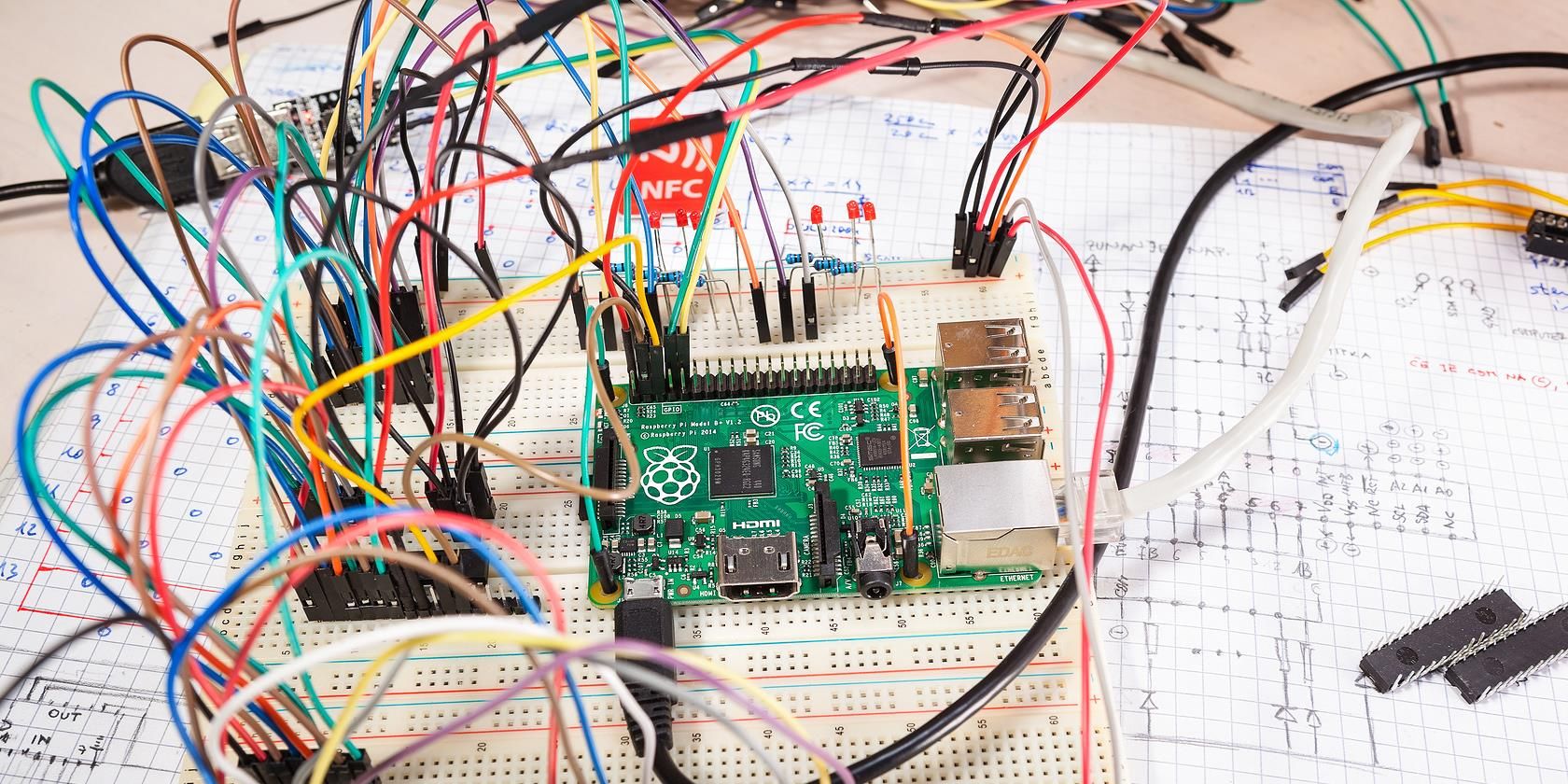
MUO
The versatility of the Raspberry Pi means that at some point you're bound to be using it outdoors, beyond the reach of your wireless network. So how can you communicate with it?
hardy plaza
heady cedar
I have pi 3 A+, no monitor or kbd, and need to install them on a university netw...
Another alternative is to set up a test OS image with a static IP address configured in /etc/dhcpcd.conf where you can set an IP address (to one available, obviously), then share an SSH key with the Pi using ssh-copy-id so you get a secure auto-login. Then you can put this SD card into each Pi, boot it up, then auto-log into it from a desktop and get its MAC address via ifconfig.
hard pike
Another great option
heady cedar
Thanks all for the ideas. @hard pike I’ll get an Ethernet cable and two usb to Ethernet adapters and give this a try. This seems like it’ll do the trick and I should have the skills for this. Still pretty new to the Pi.
hard pike
Definitely! And if that doesn’t work, the suggestion from @hardy plaza is a great option too
Probably still need the Ethernet and usb to Ethernet adapters but it might be faster 🙂
hardy plaza
hard pike
Definitely! And if that doesn’t work, the suggestion from <@828135237744984114> ...
That's basically what I do to register the MAC address of a new Raspberry Pi onto my home router. And certainly, I do have both Raspberry Pi 3 A+ and Pi Zero W's, neither which have an Ethernet connector on them.
 plush wave
hi there i'm trying to do a keyboard setup on the pico, i've used a few different codes and they give me the same answer ( it wont work ) im only try 2 pins at the moment to get it working but im not sure what im doing wrong. plus no LED is flashing after ive draged the file over.
plush wave
Is there anyone on here that can help please
 turbid rivet
plush wave
Is there anyone on here that can help please
turbid rivet
plush wave
Is there anyone on here that can help please
Do you have code or a link to a guide you followed?
plush wave
yes down to the letter
turbid rivet
plush wave
yes down to the letter
Can you share it?
plush wave
never mind all sorted but thanks anyway
civic rune
I notice that the guide adafruit has for running code on startup on a pi says "This section uses a BeagleBone Black Rev C, running a Debian Wheezy release from July 2015." Could I be having trouble making this work because I'm using raspbian?
also is there a way to find only user created services? I made one last week but can't remember the name
and does my main python code that I want to run on start need to have #!/usr/bin/python at the top?
 agile depot
Is it possible to manage/edit files on-board with the Raspberry Pi Pico? I’m trying to port some file decompression code to the RP2040, and I don’t know if it’s possible.
 lost wolf
agile depot
Is it possible to manage/edit files on-board with the Raspberry Pi Pico? I’m try...
lost wolf
agile depot
Is it possible to manage/edit files on-board with the Raspberry Pi Pico? I’m try...
Yes. Depending on what language you're using. CircuitPython for example, presents as a USB drive called CIRCUITPY on which you can edit files directly. Arduino on the other hand handles that for you, and doesn't present as a drive. The bootloader also presents as a drive regardless of language.
agile depot
So I can make some circuitpython code to decompress the file and save it on the on-board drive?
lost wolf
agile depot
So I can make some circuitpython code to decompress the file and save it on the ...
I'm not sure I understand what you mean by "code to decompress the file". Can you please try to explain?
agile depot
I have a compressed file that I saved to the pico, and I want to decompress it using some python code I found on GitHub. If I make some adjustments so the code works on the pico, could I run the file decompressor on the pico and have it save to the same location?
I wouldn’t be using any SD cards or external storage, I’m using the built in storage on the Pico
lost wolf
agile depot
I have a compressed file that I saved to the pico, and I want to decompress it u...
I think that should be possible. CircuitPython tries to be as Python-compatible as possible, but since it's running on a tiny microcontroller instead of your computer, there are features that we couldn't include due to size. So there's a distinct chance your current code might not run without some changes (and maybe not at all, if it's using a feature we couldn't include). But to run CircuitPython code, you create a file called code.py on the CIRCUITPY drive, and it will run automatically. Give a try!
agile depot
Will do, thanks
 scarlet zenith
installing packages to my pi :)
turbid rivet
Taken from https://learn.adafruit.com/circuitpython-essentials/circuitpython-storage:
"""CircuitPython Essentials Storage logging example"""
import time
import board
import digitalio
import microcontroller

# For most CircuitPython boards:
led = digitalio.DigitalInOut(board.LED)
# For QT Py M0:
# led = digitalio.DigitalInOut(board.SCK)
led.switch_to_output()

try:
    with open("/temperature.txt", "a") as fp:
        while True:
            temp = microcontroller.cpu.temperature
            # do the C-to-F conversion here if you would like
            fp.write('{0:f}\n'.format(temp))
            fp.flush()
            led.value = not led.value
            time.sleep(1)
except OSError as e:  # Typically when the filesystem isn't writeable...
    delay = 0.5  # ...blink the LED every half second.
    if e.args[0] == 28:  # If the file system is full...
        delay = 0.25  # ...blink the LED faster!
    while True:
        led.value = not led.value
        time.sleep(delay)
There are file-writing capabilities that are basically the same as that of regular python. Give it a shot!
lost wolf
Thanks @turbid rivet!
agile depot
I tried running the code last night without changes, only difference being the main python file was renamed to code.py. Does it use serial commands the same way as the command line on a PC?
It gave me some weird error that I can’t remember so I’ll check again soon
scarlet zenith
mu has failed
lost wolf
agile depot
I tried running the code last night without changes, only difference being the m...
Yes! You can use screen or tio to connect to it. Depending on your OS, you have to find the COM port, or it's in /dev/tty.* on Mac and sort of the same on Linux.
Also there's Mu editor that has the serial console built in.
scarlet zenith
talking to me? :P
lost wolf
scarlet zenith
talking to me? :P
Nope 🙂
scarlet zenith
Ah ok
Well, I tried to install it and now it looks like it failed :( 'mu-editor' gives syntax error
lost wolf
agile depot
I tried running the code last night without changes, only difference being the m...
This guide has info on the serial console - check under "Advanced Setup" for using screen, or putty. https://learn.adafruit.com/welcome-to-circuitpython
scarlet zenith
I just wanna see what the output of my pico is xD
agile depot
lost wolf
Yes! You can use `screen` or `tio` to connect to it. Depending on your OS, you h...
Oh ok, I was Ctrl+C and typing directly into the console in Mu
lost wolf
agile depot
Oh ok, I was Ctrl+C and typing directly into the console in Mu
That also works.
lost wolf
scarlet zenith
I just wanna see what the output of my pico is xD
I have no idea what has been tried so far - have you tried the "advanced" way to connect to the serial console?
scarlet zenith
Via MU? Well, Mu isn't even opening
lost wolf
scarlet zenith
Via MU? Well, Mu isn't even opening
No, I mean via a terminal program separate from the editor.
scarlet zenith
?
lost wolf
What OS are you on?
scarlet zenith
uh- linux
lost wolf
Ok, so there's a terminal program built into it somewhere. That gives you access to the command line.
This page explains the process to use a terminal program to connect to the serial console https://learn.adafruit.com/welcome-to-circuitpython/advanced-serial-console-on-linux
Basically you'll be doing what Mu does in the background.
I'm not sure why Mu isn't working for you
agile depot
I ran into a problem, the code I got uses a few modules that don't exist on the Pico as far as I know.
import argparse
import csv
import os
import re
import sys
import traceback
Not sure what to do, is there a code library for these?
scarlet zenith
YAY THANK YOU
hardy plaza
agile depot
I ran into a problem, the code I got uses a few modules that don't exist on the ...

GitHub
Core Python libraries ported to MicroPython. Contribute to micropython/micropython-lib development by creating an account on GitHub.
civic rune
my pi started not responding and only shows the desktop but with no icons. I right clicked and hit restart and nothing happened, can I just pull the plug?
lost wolf
civic rune
my pi started not responding and only shows the desktop but with no icons. I rig...
That's what I would do next, but there's always the chance of filesystem corruption, I suppose.
civic rune
shoot
lost wolf
civic rune
shoot
But sometimes it's the only option.
 pliant pebble
Yes, I would
hardy plaza
civic rune
my pi started not responding and only shows the desktop but with no icons. I rig...
You do risk filesystem corruption, so what I'd do in the future (and I even do this on my desktop Linux computers) is enable ssh, so that when the desktop locks up you can ssh in remotely and reboot.
agile depot
hardy plaza
https://github.com/micropython/micropython-lib/tree/master/python-stdlib
What does this do? I see it has argparse but some other things like csv and sys arent there
civic rune
 pliant pebble
That's happened to me a few times, and I just pulled the plug, and I didn't corrupt my FS - not saying you should, but....
hardy plaza
I have a pesky Ubuntu desktop install whose graphics card now and then locks up in Firefox (ugh) so I have to ssh in now and then. If you pull the plug on a Linux OS you risk filesystem corruption. If it didn't happen you were lucky, that's all.
civic rune
civic rune
anyone know what htis means?
ah I got to ca command prompt with CTRL C but then it started again
how can I force shutdown from here?
pliant pebble
hardy plaza
I have a pesky Ubuntu desktop install whose graphics card now and then locks up ...
I agree
pliant pebble
civic rune
how can I force shutdown from here?
sudo shutdown -r now
civic rune
it's printing messages too fast for me to type in that command
pliant pebble
It looks like your FS crashed - but I can't read it that well
pliant pebble
I would
hardy plaza
agile depot
What does this do? I see it has argparse but some other things like csv and sys ...
Those are MicroPython ports of the CPython code, an ever-expanding list. You install them on your MCU. I'm currently using about five of them, including asyncio. sys won't be there but its functionality is supplied by other libraries like machine. csv will be supplied by an external library or not at all, may be a work in progress. Not everything has been or ever will be ported as it's a volunteer effort and things get prioritised by what the volunteers want (i.e., you could contribute csv).
pliant pebble
Oh, shoot
hardy plaza
civic rune
idk what they mean
Your ext4 filesystem is what's called journaling, which means that it keeps a journal of changes that are meant to be applied in the future to update the actual stored filesystem from the changes that are meant to happen. If you restart in the middle of things due to a crash the filesystem attempts to apply the journal to catch up. If successful it recovers, if it fails you have a corrupted filesystem.
pliant pebble
Did you have backups? I always backup my OS every week
civic rune
I do
civic rune
my SD card is showing 0.0 GB available
agile depot
I tried running the code i found without any editing to see what errors it would give me but the error i got isnt very helpful:
Traceback (most recent call last):
  File "<stdin>", line 1
SyntaxError: invalid syntax
I dont see a file called "<stdin>"
pliant pebble
I'm guessing it's in a library
civic rune
pliant pebble
*formatting*
What do you mean?
lost wolf
civic rune
What do you mean?
The ... partition is I think the word I'm looking for... the partition was damaged, most likely.
pliant pebble
Balena Etcher is useful for formatting and re-imaging the card
civic rune
ah ok
lost wolf
What g3holliday said.
There's also the SD Formatter from SD, I think, if Etcher has issues with it. Then you can use Etcher to image it once it's formatted.
pliant pebble
If you're on Mac - Disk Utility is a good formatting tool (if you don't want to install anything)
SD formatter is much better though
civic rune
ok so I need to reformat the drive? I'm using a spare now
pliant pebble
Yes, and preferably install a backup, or if you didn't have anything important on the drive, install Bullseye
civic rune
I'm working on figuring out a way to get the image into a file so I can just reload a working image
lost wolf
civic rune
I'm working on figuring out a way to get the image into a file so I can just rel...
What OS are you using?
There are cloning apps that do that.
civic rune
windows on my PC, default raspbian for the pi
lost wolf
PC was what I meant. I don't use Windows enough to be helpful with app names.
civic rune
no worries
I have an iPad but I doubt iPadOS is set up to do this
I'm failing to convince my work to buy me a computer, I'm just using my personal laptop rn
lost wolf
But I imagine something exists, there's one for Mac called Carbon Copy Cloner (which might also be available for Windows?), that can copy to and from disk images really easily.
civic rune
hmm maybe I know someone with a mac I can borrow if I can't find a windows utility
lost wolf
Not sure it's available for free though. But I bet something is.
civic rune
eh, if it's under 50 dollars I can probably get them to pay for it
pliant pebble
civic rune
I'm failing to convince my work to buy me a computer, I'm just using my personal...
Same
lost wolf
Looks like most of the options I could find quickly are under 50.
CCC is not available for Windows though.
pliant pebble
Most software I look at is under 50
I don't have the budget for most stuff over 50
civic rune
Should I use sudo pip3 to install the adafruit 74hc595 library?
civic rune
ok let me look up how to make python3 my default python too
pliant pebble
Yeah
 opaque wagon
win32diskimager is a good one for writing and reading disk images (on windows obv)
civic rune
ok, so I first need to find a way to write the disk image from the pi to a USB stick, right?
opaque wagon
no, you can write the disk image to a file
like get iso of disk 🙂
civic rune
Huh, what would I google?
Doesn't the disk image take up a lot of space?
like the exact amount of space on the pis SD card?
civic rune
Trying to understand this code from this guide (https://www.tomshardware.com/how-to/back-up-raspberry-pi-as-disk-image ) sudo dd if=/dev/mmcblk0 of=[mount point]/myimg.img bs=1M What does this do? Trying to understand and not just copy/paste stuff too much

Tom's Hardware
Turn your Raspberry Pi microSD card into a small .img file you can share or take anywhere.
steady rose
copies /dev/mmcblk0 to [mount point]/myimg.img
if = in file (file to read from)
of = out file (file to write to)
bs = how many bytes to read/write at a time
sudo = because dd needs to run with elevated privs
civic rune
sooooo ok thank you! That makes sense. I should have just looked up bash commands
opaque wagon
civic rune
like the exact amount of space on the pis SD card?
yes it will though, but you can zip compress it which can help
civic rune
is that what pishrink.sh does here?

gahh having a hard time typing this out because discord keeps putting my text into code blocks when I use `
one sec let me fiddle
what is the difference between sda and `-sda1? same with sdb and `-sdb1
 umbral sable
civic rune
what is the difference between sda and \`-sda1? same with sdb and \`-sdb1
umbral sable
civic rune
what is the difference between sda and \`-sda1? same with sdb and \`-sdb1
The punctuation is actually trying to draw an ASCII line. It's showing that the partition sda1 is part of (underneath) the drive sda.
umbral sable
Like a business org chart... it's a piece of a bigger thing, so it's shown as indented.
civic rune
huh ok, not getting it but I'll see what I can google
umbral sable
Think of like a book table of contents. Chapter 1, section 1-1, etc.
umbral sable
That indicates the partition spans the whole drive.
civic rune
ahhhhh ok that clicked
so if I partitioned my 256 (232.9 irl) drive it would show up as two diff values?
umbral sable
Yep, just like mmcblk0 below, which has two partitions.
civic rune
ahhh nice
so this sudo dd if=/dev/mmcblk0 of=[mount point]/myimg.img bs=1M becomes:
sudo dd if=/dev/mmcblk0 of=/media/pi/24B655B9B6558BE4/myimg.img bs=1M?
umbral sable
Yes, that would image your internal flash to an image file on the 256G flash drive.
civic rune
and do I not need to worry about -mmcblk0p1 and -mmcblk0p2?
I see that the code only calls up -mmcblk0
umbral sable
Imaging the disk as a whole will include all partitions on it.
civic rune
ahhhh ok
that makes sense. Thanks as always.
how can I change the name of the drive from 24B655B9B6558BE4 to something more readable?
umbral sable
It's a little involved, but the short answer is the mlabel command. https://help.ubuntu.com/community/RenameUSBDrive
civic rune
hmm maybe I don't need to rename it. I'm literally just using this drive to get the image onto my main PC to backup on github. I haven't figured out how to get to my repo from the pi
weird, when I tried properties -> rename it gave me a permissions error, why would that be?
lost wolf
Because you had to sudo create it in the first place? So you need to sudo to rename it? (Guessing here.)
lost wolf
civic rune
but I didn't use sudo on the drive in the past
It was a stretching guess on my part.
civic rune
no worries, thanks for chiming in 🙂
civic rune
civic rune
I notice that the guide adafruit has for running code on startup on a pi says "T...
I have a fresh pi so I'm going to start again, but could this be an issue?
and do I need #!/usr/bin/python at the top of my python script?
steady rose
the guide is a little dated in terms of the mention of BBB and wheezy. but the generic systemd example should still work ok.
you need the shebang if you want to run the .py file as a command, like:
pi:~ $ foo.py
vs explicitly running it with python, like:
pi: ~ $ python3 foo.py
and i think this is the more preferred shebang?
#!/usr/bin/env python
or maybe even with python3
civic rune
ah ok, so in this case I want the shebang right?
Here's what my service file looks like:
[Unit]
Description=12 Days Code

[Service]
ExecStart=/home/pi/Desktop/12days2.py
StandardOutput=null

[Install]
WantedBy=multi-user.target
Alias=12days.service
My file in nano is called 12days.service, I want that to match my Alias, right?
steady rose
yes
civic rune
ok cool, let me finish the guide and give this a shot!
steady rose
12days2.py should have the shebang line and also be chmod +x
steady rose
makes it executable
civic rune
also in nano, do I use ^O to save the file?
civic rune
ok cool thanks
when I ran sudo systemctl enable 12days.service I got:
Created symlink /etc/systemd/system/12days.service ??? /lib/systemd/system/12days.service
Created symlink /etc/systemd/system/multi-user.target.wants/12days.service ??? /lib/systemd/system/12days.service
Anything seem wonky?
steady rose
looks ok
steady rose
not sure
civic rune
ok no worries I'll just assume they are normal
steady rose
it didn't gripe though. no obvious errors.
steady rose
you can just enable without reboot
sudo systemctl status 12days.service
to check current state
sudo systemctl start 12days.service
to start
and can then run the status command again
civic rune
hm ok when I ran sudo systemctl status 12days.service I got:
??? 12days.service - Twelve Days of Christmas Code
  Loaded: loaded (/lib//systemd/system/12days.service; enabled; vendor preset: enabled
  Active: inactive (dead)
~
~
~
~
~
~
~
~
~
~
~
~
~
~
~
does the Active: inactive (dead) mean anything?
steady rose
try starting it and running status again
lost wolf
Such a clear message 😄
civic rune
at the bottom there's a message saying:
lines 1-3/3 (END) but I can't get out of this dialog menu/area
civic rune
ctrl c worked
civic rune
steady rose
`sudo systemctl start 12days.service`
nothing happened when I ran this code
civic rune
ok status gave me a bunch of errors, too many to type out, let me take a picture
I'd get on discord on the pi but it reallllly struggles there
Not sure how visible this is. Lmk if I should take two close shots

a syntax error it seems like?
let me open it in nano again
would that be sudo nano /lib/systemd/system/12days.service?
civic rune
I just ran it from Thonny and it ran fine
let me try from the cmd line see if anything happens differently
would that be python /home/pi/Desktop/12days2.py?
steady rose
not from thonny
from command line
pi:~ $ /home/pi/Desktop/12days2.py
basic idea is to manually do same thing the systemd service is try to do
which is the ExecStart line in the file
civic rune
got a bunch of errors like import: command not found as well as a syntax error
ahhh I forgot the shebang
steady rose
it worked in thonny because that's different. doesn't need a shebang, etc.
steady rose
what do you get from which python3?
civic rune
heyyyy
it's working!
now how can I stop the code from running from the command line?
steady rose
same as start, but with stop
civic rune
yeah this is pretty neat
let me try rebooting and see if it starts on startup like it's supposed to
steady rose
yep. good next test.
civic rune
so I'll need to go into the cmd line and run sudo systemctl stop 12days.service if I don't want the code to be running?
opaque wagon
yes
civic rune
noiice
opaque wagon
but if you want it to stop starting on boot, use the disable command i think 
(enable to well, enable)
steady rose
yah...i think so too. that's what the disable/enable step is about. so don't need to delete the service file or anything.
can toggle boot behavior that way
civic rune
also if you really don't like christmas music, don't take a job that requires you to listen to it on repeat while debugging. Just a free pro tip
opaque wagon
just make sure it's not all i want for christmas is you
civic rune
opaque wagon
~~just make sure it's not all i want for christmas is you~~
I would refuse to work on that also we can't afford the licensing
opaque wagon
haha
opaque wagon
civic rune
hm ok when I ran `sudo systemctl status 12days.service` I got:
```
??? 12days.se...
btw you also don't need the .service part at the end of the service name - systemd will find it (saves typing but i'm pretty sure the tab autocomplete will put it in so either way)
civic rune
oh weird. the song "hung" while playing for a second. Randomness from pygame?
civic rune
ok let's hope
opaque wagon
any exceptions?
civic rune
I'm running it on boot so it's not printing exceptions anywhere
opaque wagon
actually if it crashes systemd would save it (systemd saves the like last 10 lines of output from your program) but your service file redirects stdout to null
civic rune
how can I change that? and is that /dev/null?
opaque wagon
i thinik so
(as you can tell i don't really know what i'm doing)
remove the StandardOut = null line from your service file and do a daemon-reload and sudo systemctl restart 12days
civic rune
will just straight removing it cause exceptions to go to the normal place?
opaque wagon
no (if you mean normal place = console)
but systemd saves a bit of program output so if it ever crashes you can see it with status command
civic rune
ah ok
I'll do a reboot again and see if it happens again. If it was just once I can live with it
opaque wagon
idk if you want this but you can also get it to restart if it crashes: (add to [Service] section of service file)
Restart=on-failure
RestartSec=10
(got from https://www.howtogeek.com/687970/how-to-run-a-linux-program-at-startup-with-systemd/)
civic rune
I'd rather it not try again I think, idk why though
ok time to write up what I've learned so I don't lose this progress
opaque wagon
🙂 also if it works i would do backup of code + service file at least
so you don't have to rewrite everything again
civic rune
yeah my next step is a backup of a working image, put on github
I'm actually employed in part because there were no backups of htis system, so I had to start from scratch
Good learning experience but a tad annoying
how can I create just a basic text file on the pi? Do I have to use nano?
opaque wagon
for an empty file you can do touch <filepath>
for one line of text you can do echo "the one line text" > filepath
note that the echo and > will overwrite the file if it exists
civic rune
one sec, gotta step off and complete open enrollment stuff. Gotta make my sister my beneficiary for life insurance. My dog doesn't have a SSN unfortunately
hm, our insurance isn't that bad. 30/300/50%
that's kinda #general-chat sorry
civic rune
how do I use nano to open my service to edit it?
figured out opening it, when saving it do I just write out and use the same filename to overwrite?
lost wolf
civic rune
figured out opening it, when saving it do I just write out and use the same file...
Ctrl+x, y I think.
Yeah basically.
It's kind of confusing.
lost wolf
Oh. Fair enough. I do CTRL+X, and then hit y when it asks if I want to save and overwrite or whatever it asks.
Kind of like there are multiple ways to save in vim.
I'm sure.
civic rune
write_out didn't work let me try your way
lost wolf
Stern warning if you say "no" you'll lose your work, iirc.
I don't use it that often... only when I need to quick edit something and am afraid I'll screw it up in vim. Because I'm kinda bad at vim.
civic rune
it's asking me to write a filename, use the same one I assume?
dang, it doesn't seem to have made the changes
civic rune
I did use sudo
opaque wagon
civic rune
dang, it doesn't seem to have made the changes
if you mean no changes to the service, then you need to do sudo systemctl daemon-reload
civic rune
hmmm
let me re do the changes and try that
didn't seem to do the trick but let me try again
 nova karma
is anyone else getting errors imaging raspberry pi os bullseye 64bit? My download's image checks out, but I keep getting failed checks after writing. tried different sdmicro's and different usb adaptors
using balenaEtcher on windows, imaged pi OS success fully bunches of times before
and an ubuntu server image just flashed fine. I wonder if something in the image didn't get updated so that etcher can verify properly
 elder palm
anyone else having issues with their raspberry pi 400 and the hyperpixel 4 non-touch staying blank
the only thing i can find is something to do with some diode on pin 12.
civic rune
I got some feedback that using /lib/systemd/system is "wrong" and that /etc/systemd/system is better. Anyone have an opinion?
opaque wagon
Every guide I remember reading used /etc - never seen /lib used for systemd
civic rune
Yeah the adafruit guide uses /lib it seems
heady cedar
Is there a way to use raspi-config or some other tool to add another network? I can get set up on multiple networks if I use a file like the enclosed screenshot in what-supplicant at setup. Is my best bet returning the card to a card reader, adding this file again, then rebooting the pi with this new file? Trying to figure out easiest procedure to coach students through. Thanks!
 plush wave
Morning all, slight problem I've used a code from a YouTube video it says there is a problem with the digitalio line any ideas
Using a pi pico
plush wave
back on the cpu, here is the error message
%cd 'E:'
%Run code.py
Traceback (most recent call last):
File "E:\code.py", line 2, in <module>
import digitalio
ModuleNotFoundError: No module named 'digitalio'
i thought i fixed it yesterday but i was wrong
ruby night
@plush wave It looks like you are trying to tun the code.py on your host computer, not on the pico. Have you installed CircuitPython on the Pico?If you want to see the code run on the pico, you have to open a terminal session to have access to the REPL. This guide may help you get started https://learn.adafruit.com/welcome-to-circuitpython
plush wave
ruby night
<@!452500665210503169> It looks like you are trying to tun the code.py on your h...
Circuitpython is installed
ruby night
how are you connecting to the Pico?
ruby night
heady cedar
Is there a way to use raspi-config or some other tool to add another network? I ...
the wpa_supplicant.conf file is stored on the Pi in /etc/wpa_supplicant/wpa_supplicant.conf You can edit it there and save it. It does require editing as 'sudo' since it is owned by 'root'
@plush wave I don't understand what this is doing ```%cd 'E:'
%Run code.py
Traceback (most recent call last):
File "E:\code.py", line 2, in <module>
import digitalio
ModuleNotFoundError: No module named 'digitalio'
Or maybe I am misunderstanding what you are doing. Have you used CircuitPython before?
plush wave
ruby night
Or maybe I am misunderstanding what you are doing. Have you used CircuitPython b...
Not really, learning the basics of keyboard command with switch, thought the video would he a good place to start
I duplicated the code letter by letter and got this
Error
ruby night
How are you connecting to the Pico?
plush wave
Via USB to laptop
ruby night
I meant are you creating a terminal session via the Mu editor or something like Putty --- or are you just going to the E: drive and trying to execute the code.?
plush wave
I'm using thorny to code
ruby night
ah -- OK -- make sure you are executing the code on the Pico and not on your computer.
plush wave
I did that clicked save then run the program unless I'm missing a step
ruby night
in the terminal window can you type 'help('modules')` ? What does it show?
And you have CircuitPython installed, not MicroPython? correct?
ruby night
what is -- Micropyhton or CircuitPython? -- how did you install it?
plush wave
Download, copy and paste onto the board then it reloaded it self
ruby night
What file did you download and install?
plush wave
Give me 1 min need the laptop up. Its what I found on YouTube, and called adafruit circuitpython hid
ruby night
When you can, post a link to the video. as well as the name of the file you installed.
plush wave
heres the video

Using the all new Raspberry Pi Pico to create an DIY Macro Keyboard much like a stream deck with a few tactile switches and circuit python. thanks for the view!
○○○ LINKS ○○○
Circuit Python ► https://circuitpython.org
Microcenter RPi Pico ► https://micro.center/aax
Raspberry Pi Pico ► https://pico.raspberrypi.org
○○○ SHOP ○○○
Novaspirit Sho...
ruby night
OK -- it mentions the adafruit circuitpython hid being "pre-installed" how did you install it? Where did you get it?
plush wave
GitHub
USB Human Interface Device drivers. Contribute to adafruit/Adafruit_CircuitPython_HID development by creating an account on GitHub.
ruby night
That is a library -- I am confused about what is installed on your Pico -- Can you post a screenshot of what you see in Thonny when you start up?
What version of CircuitPython did you install? how did you install it?
If you can post a screen shot of running the help('modules') that would help...
I'm afraid I have to go away -- I hope someone else can help... I suspect you do not actually have CircuitPython installed but I need more information to confirm that.
this video from novaspirittech may help https://www.youtube.com/watch?v=onBkPkaqDnk. He shows how to install CircuitPython as well as the library. This guide from adafruit is also a good place to start.https://learn.adafruit.com/getting-started-with-raspberry-pi-pico-circuitpython/overview
plush wave
i think i've missed a step just need 10 mins to go through it all over again
ruby night
Good luck -- I'll be away for the next hour or so.
plush wave
found the issue i think CircuitPython 7.0.0 is not loading in correctly. i download it of the website open up the zip file copy and paste the file on to the pico then when i open thonny its not seeing it
CircuitPython 7.0.0 is not working at allm i have the error notice but is bloody big
never mind forgot to select interperter i had it on microphton, next stage
turbid rivet
@faint sparrow If you're looking for a USB to WiFi, you might be better off with one something like this: https://www.amazon.com/TP-Link-wireless-network-Adapter-SoftAP/dp/B008IFXQFU/

Maximum wireless transmission rates are the physical rates derived from IEEE Standard 802.11 specifications. Range and coverage specifications are based upon test results under normal usage conditions. and will vary as a result of 1) environmental factors, including building materials, physical o...
plush wave
ruby night
Good luck -- I'll be away for the next hour or so.
all working now bud, thanks for your help
ruby night
Congratulations! Have fun with it!
heady cedar
Any recommendations for migrating students who have been using Mu cod microcontroller CircuitPython to Raspberry Pi code editing? We’ve been just pasting into Nano when sshing in. No way to Mu on the Pi is there? Does Thomy work with CircuitPython on the Pi?
 tired marsh
heady cedar
Any recommendations for migrating students who have been using Mu cod microcontr...
tired marsh
heady cedar
Any recommendations for migrating students who have been using Mu cod microcontr...
is it only a headless setup ? If not, you can pip install Mu on a Pi.
Unless I'm mistaken, it should work.
heady cedar
It is headless. They use terminal to ssh in & vnc isn't tough to setup. Can you Mu on the Pi over VNC & use CircuitPython? It would be slow, bur I could give this a try.
Very new to Pi, so these are newbie questions, but am trying to run the script at: https://learn.adafruit.com/circuitpython-on-raspberrypi-linux/installing-circuitpython-on-raspberry-pi
sudo pip3 install --upgrade adafruit-python-shell
wget https://raw.githubusercontent.com/adafruit/Raspberry-Pi-Installer-Scripts/master/raspi-blinka.py
sudo python3 raspi-blinka.py```
Output is this:
```Updating System Packages
Blinka Hit:1 http://archive.raspberrypi.org/debian bullseye InRelease
Blinka Hit:2 http://raspbian.raspberrypi.org/raspbian bullseye InRelease
Blinka Reading package lists...
Upgrading packages...
Blinka E: Broken packages

Blinka Reading package lists...
Blinka Building dependency tree...
Blinka Reading state information...
Blinka Calculating upgrade...
Blinka Some packages could not be installed. This may mean that you have
Blinka requested an impossible situation or if you are using the unstable
Blinka distribution that some required packages have not yet been created
Blinka or been moved out of Incoming.
Blinka The following information may help to resolve the situation:
Blinka
Blinka The following packages have unmet dependencies:
Blinka vlc-bin : Depends: libvlc-bin (= 3.0.16-1+rpi1+rpt1) but 3.0.16-1+rpi1+rpt2 is to be installed
Blinka vlc-plugin-skins2 : Depends: vlc-plugin-qt (= 3.0.16-1+rpi1+rpt2) but 3.0.16-1+rpi1+rpt1 is to be installed
Blinka Exiting due to error: Apt failed to install software!```
Unsure what "is to be installed" means. Can I do anything to correct this & does it impact the installation of Blinka/CP on this device? Thanks!
Adafruit Learning System
Make hardware and interface with sensors super easy using CircuitPython
I'm using the latest Bullseye. Just downloaded & installed yesterday.
Solution found (in case anyone runs into this). I opened the VNC desktop, ran the upgrade from the upper-right pulldown, the VNC issues seemed to go away. I could then rerun the blinka script. Just ran blinkatest & it seems to work.
heady cedar
Transferring files between the Mac & Pi is super-easy with Netatalk. I can also connect to the Pi as an external volume via the finder, so I can save Mu files to my Pi. Console doesn't work for execution, but I can run code in ssh so at least we get a familiar editor. Is there a similar tool for windows? Is WinSCP what most folks use for transferring fileis from Win to the Pi?
tired marsh
you can run windows file sharing on the pi too
I tend to prefer using SSH (SFTP) with Cyberduck (on mac, it's also on windows), it's free and lets you open the files in any app and uploads the changes, but it doesn't work right with Mu
heady cedar
@tired marsh thanks. So nothing special needs to be used to access the Pi on Windows as long as they're on the same network? It'll appear in a sort of Network icon? (On the Mac there's a network icon one clicks & the network volumes show up - after netatalk is installed, the Pi is there). Appreciate your kind help - this is really useful to me!
tired marsh
you would have to install Samba on the pi to get the windows file sharing
 wanton holly
if i run a raspi 3B+ headless , how much more compute power can i have ?
steady rose
relative to what?
 faint sparrow
turbid rivet
<@456226577798135808> If you're looking for a USB to WiFi, you might be better o...
faint sparrow
turbid rivet
<@456226577798135808> If you're looking for a USB to WiFi, you might be better o...
Ok, thx 👍
I was wrong I didn't meant USB to Ethernet, I mean GPIO to Ethernet because I've an Ethernet switch connected to a CPL Kit right under my monitors
turbid rivet
faint sparrow
I was wrong I didn't meant USB to Ethernet, I mean GPIO to Ethernet because I've...
Ahhh, so you're looking for an Ethernet HAT of some sort. Adafruit used to carry one, but it's since been discontinued. Waveshare has a nice Ethernet / USB Hub HAT that might be a good fit? https://www.amazon.com/Ethernet-USB-HUB-HAT-Compatible/dp/B07T16RSFM
agile depot
Could the RP2040 technically emulate the Pico-8 computer on a 128x128 display? I’m working on a Lua to Python translater and I don’t know if it can refresh sprites and tiles fast enough
The specs of the computer can be found here: https://pico-8.fandom.com/wiki/Pico8

PICO-8 Wiki
PICO-8 (or "Pico-8") is a fantasy console by Lexaloffle Games for making, sharing, and playing small computer games and programs.
PICO-8 is available for purchase as an app for Windows, Mac OS X, Linux (Intel), and Raspberry Pi. It also came bundled with the PocketC.H.I.P. portable computer. See the PICO-8 website for purchasing information.
PIC...
 solar meteor
I've got mosquitto running as a MQTT broker on my Pi. Is there a way to see all past topics?
 clever venture
Hello everyone I need help setting up my PMSA0031 adafruit AQI sensor in raspberry pi 4
civic rune
What issues are you encountering?
clever venture
I'm trying to use the code that's providing by the adafruit website in pythong, but I get errors
let me know if you want to check the error and the code screenshot
civic rune
Yeah you can directly upload your code as well as paste the full exception trace. That's usually what folks ask for around here. Can't guarantee I can fix it but it'll help others who can help
civic rune
Yup! If it's not proprietary

 civic rune
your red wire is tied to ground, not 5V. Make absolutely sure that you need 5V and not 3.3V
(it looks like your red wire is tied to ground rather, not 100% sure)
clever venture
Oh yeah I accidently did that a minute ago
civic rune
that's a fun sensor, I have one lying around. It's really easy to work it ime
clever venture
thank you
I have a project demonstration next Monday and I'm struggling with this
civic rune
what errors are you getting?
clever venture
let me send you the code first


it doesn't recognize "import board", import busio" all of them from line 1 through line 5

 civic rune
ahh did you install blinka?
Adafruit Learning System
Make hardware and interface with sensors super easy using CircuitPython
clever venture
no I didn't
civic rune
make sure you do that first, blinka allows you to use modules like board. You'll also need to install the library for the sensor
lost wolf
civic rune
make sure you do that first, blinka allows you to use modules like `board`. You'...
I think installing the sensor lib should install Blinka. As long as the library is setup right.
civic rune
ahhh ok
lost wolf
I think....
civic rune
I assumed they didn't have blinka installed because of the error they got. But you'd be able to tell in the terminal window if it's installing blinka at the same time you install the sensor lib
lost wolf
civic rune
I assumed they didn't have blinka installed because of the error they got. But y...
I'm pretty sure you're right they don't have Blinka installed. I was simply letting you know you could, in theory, eliminate one step there.
civic rune
ahhh ok thanks! Always looking for efficiencies
lost wolf
I say "If it's setup right" because I had to fix a similar issue in a special library earlier today, so I always caveat it with that in case the lib needs an update.
clever venture
I just install the blinka and the system is rebooting
is there any library that I have to install as well?

After installing the blinka the previous errors are cleared but now its giving me error for the DigitalIInOut
lost wolf
clever venture
After installing the blinka the previous errors are cleared but now its giving...
difitialio is misspelled. It should be digitalio. And yes, you need to install the PM25 library.
clever venture
Can you please guide me how to install that?
lost wolf
pip install adafruit-circuitpython-pm25 I believe. The PM2.5 guide should have the rest of the instructions if there are any: https://learn.adafruit.com/pmsa003i/python-circuitpython#python-installation-of-pm25-library-3067526-7

Adafruit Learning System
Breathe easy, knowing that you can track and sense the quality of the air around you!
clever venture
Thank you so much guys
civic rune
Might need pip3
lost wolf
Ah good call. Yep. I am not good at thinking about that because my setup doesn't need it.
civic rune
Yeah I always change Python to Python3 first thing so I don't have to worry about it. I literally never need Python 2
Unless I want to write some insecure banking software used by millions. Looking at you, major banks
clever venture
civic rune
Might need pip3
I used pip3


the code says "Unable to find the PM2.5 device"
steady rose
are these pins soldered?

wiring on pi side is also odd. not sure if you're trying something different?
https://learn.adafruit.com/pmsa003i/python-circuitpython#python-computer-wiring-3067520-4
 clever venture
steady rose
are these pins soldered?
clever venture
steady rose
are these pins soldered?
thank you
@lost wolf @civic rune @steady rose you guys are awesome. Thank you so much
lost wolf
You're welcome! Glad you got it sorted out!
civic rune
Yay! Glad any time I can be of assistance. I have a lot of paying it forward to do :)
clever venture
 civic rune
Woooooo
clever venture
We have a project demonstration on Monday
clever venture
Yeah, I was so stressed about that, but I’m really glad we got this done today
civic rune
One tweak I might add is changing
Particles > 0.3 um... to
Particles -> 0.3 um... or even
Particles - 0.3 um...
The current way sort of reads as "Particles greater than ..."
late holly
The cable I got as an accessory for the Pi Zero WH allows me to connect one USB peripheral such as USB keyboard. What adaptor do I need to connect both USB keyboard and USB mouse?
civic rune
Which cable did you get?
Ah I see the one adafruit sells.
Hm I'd get a USB expander dongle. Pretty inexpensive
late holly
Thanks @civic rune - Can you share a link to the USB expander dongle?
civic rune
Sure it's not an adafruit product, I just got mine at best buy

Best Buy
Shop Insignia™ 4-Port USB 3.0 Hub Black at Best Buy. Find low everyday prices and buy online for delivery or in-store pick-up. Price Match Guarantee.
tired marsh
any USB hub
I found a tiny 2 ports hub with a short cable, let me see if I can find it
late holly
Thanks @civic rune
tired marsh
oh of course the entry doesn't exist anymore on amazon
civic rune
late holly
Thanks <@887510739462537236>
Any time!
late holly
tired marsh
oh of course the entry doesn't exist anymore on amazon
Thanks @tired marsh for checking
heady cedar
Yesterday I posted that I ran into the problem below using a fresh Bullseye install on a Pi 3A+:
https://learn.adafruit.com/circuitpython-on-raspberrypi-linux/installing-circuitpython-on-raspberry-pi
I could get around this by VNCing into the Pi and select the "upgrade" icon from the desktop. If folks haven't installed VNC yet, is there a work-around to perform any upgrade? I did an apt-get update & upgrade as indicated in the docs before installing this. Are there any additional gotchas in using Blink with Bullseye worth noting? Thanks!
Blinka Reading package lists...
Upgrading packages...
Blinka E: Broken packages

Blinka Reading package lists...
Blinka Building dependency tree...
Blinka Reading state information...
Blinka Calculating upgrade...
Blinka Some packages could not be installed. This may mean that you have
Blinka requested an impossible situation or if you are using the unstable
Blinka distribution that some required packages have not yet been created
Blinka or been moved out of Incoming.
Blinka The following information may help to resolve the situation:
Blinka
Blinka The following packages have unmet dependencies:
Blinka vlc-bin : Depends: libvlc-bin (= 3.0.16-1+rpi1+rpt1) but 3.0.16-1+rpi1+rpt2 is to be installed
Blinka vlc-plugin-skins2 : Depends: vlc-plugin-qt (= 3.0.16-1+rpi1+rpt2) but 3.0.16-1+rpi1+rpt1 is to be installed
Blinka Exiting due to error: Apt failed to install software!```
Adafruit Learning System
Make hardware and interface with sensors super easy using CircuitPython
steady rose
This was the "full" version of RPI OS?
it sounds like apt-get update / upgrade from command line did not fully work? but using some "upgrade" thing from the desktop UI did work?
in general, it looks like some kind of OS update/upgrade thing not working. but once past that, Blinka is working ok?
heady cedar
I selected the first upgrade option, the default option, in the Raspberry Pi imager. When accessing the desktop icon to update, yes, this did install Blinka properly. I'm trying to minimize steps (and also learn a few things).
The apt-get upgrade says:
requested an impossible situation or if you are using the unstable
distribution that some required packages have not yet been created
or been moved out of Incoming.
The following information may help to resolve the situation:

The following packages have unmet dependencies:
 vlc-bin : Depends: libvlc-bin (= 3.0.16-1+rpi1+rpt1) but 3.0.16-1+rpi1+rpt2 is to be installed
 vlc-plugin-skins2 : Depends: vlc-plugin-qt (= 3.0.16-1+rpi1+rpt2) but 3.0.16-1+rpi1+rpt1 is to be installed
E: Broken packages
 humble marsh
heady cedar
I selected the first upgrade option, the default option, in the Raspberry Pi ima...
humble marsh
heady cedar
I selected the first upgrade option, the default option, in the Raspberry Pi ima...
I have done apt-get dist-upgrade (now also called full-upgrade, at least on some distributions) for years, which does a more complete job of upgrading. I am not sure it is applicable here, but it won't hurt.
steady rose
i ran through the process, per that linked guide, on a pi zero 2 w using the latest (2021-10-30) lite version and ran into no issues
downloading desktop version now and will try that also
since it's something with vlc, which i doubt is in the lite release
steady rose
recreated:
pi@raspberrypi:~ $ sudo apt-get update
Get:1 http://archive.raspberrypi.org/debian bullseye InRelease [23.5 kB]
Get:2 http://raspbian.raspberrypi.org/raspbian bullseye InRelease [15.0 kB]
Get:3 http://raspbian.raspberrypi.org/raspbian bullseye/main armhf Packages [13.2 MB]
Get:4 http://archive.raspberrypi.org/debian bullseye/main armhf Packages [205 kB]
Fetched 13.5 MB in 38s (352 kB/s)
Reading package lists... Done
N: Repository 'http://archive.raspberrypi.org/debian bullseye InRelease' changed its 'Suite' value from 'unstable' to 'stable'
pi@raspberrypi:~ $ sudo apt-get upgrade
Reading package lists... Done
Building dependency tree... Done
Reading state information... Done
Calculating upgrade... Done
Some packages could not be installed. This may mean that you have
requested an impossible situation or if you are using the unstable
distribution that some required packages have not yet been created
or been moved out of Incoming.
The following information may help to resolve the situation:

The following packages have unmet dependencies:
 vlc-bin : Depends: libvlc-bin (= 3.0.16-1+rpi1+rpt1) but 3.0.16-1+rpi1+rpt2 is to be installed
 vlc-plugin-skins2 : Depends: vlc-plugin-qt (= 3.0.16-1+rpi1+rpt2) but 3.0.16-1+rpi1+rpt1 is to be installed
E: Broken packages
pi@raspberrypi:~ $
does it make any difference if you do dist-upgrade?
steady rose
what's a good tag for syntax highlight shell output like above? tried bash,sh, console
@humble marsh that worked
ruby night
lately, Ive been using sudo apt update then sudo apt full-upgrade I "think" that is similar to dist-upgrade
heady cedar
Yes - sudo apt full-upgrade solved the problem. Thanks so much (my students thank you, too)! Added a sudo apt clean to the end of the instructions.
steady rose
@humble marsh ^^ think this is something worth updating guides?
humble marsh
steady rose
<@!329766224093249548> ^^ think this is something worth updating guides?
yes, definitely
i found that upgrade was often not sufficient. It's supposedly not as "safe", but I've never seen that to be a problem. It seems to cause more problems than it solves.
steady rose
it seems like there is some general updating of the whole apt-get vs apt tooling? happening in linux land in general. not pi specific.
humble marsh
steady rose
it seems like there is some general updating of the whole `apt-get` vs `apt` too...
I think full-upgrade was made a synonym for dist-upgrade just because it's clearer. apt vs apt-get: I discovered a few years ago apt was sufficient, at least on the distros I was using, and I am a lazy typist
and yes, this is on Ubuntu, so def not pi-specific
steady rose
just thinking in terms of guides...can update...but if it's an ongoing moving target, then not sure
is apt then new apt-get?
is full-update/dist-upgrade then new upgrade?
etc
 umbral sable
 sturdy blade
Is it possible to use raspberry pi to read a analog co sensor without a adc chip...
sturdy blade
Is it possible to use raspberry pi to read a analog co sensor without a adc chip...
The short answer is no. The long answer is that there are various circuits which can be made to function as a poor man's ADC.
sturdy blade
Okay thanks. I will order a adc then
 runic yoke
Hi! Is it ok for me to ask for big-picture advice about raspberry pi-based projects here? I'm designing a system that will involve using raspberry pi's, GPIO and an app, and I'm trying to figure out what the best choices are for communication methods and media handling
I know that's pretty generic, but I wanted to see if that's the kind of stuff that's ok to post before diving into the details.
umbral sable
runic yoke
I know that's pretty generic, but I wanted to see if that's the kind of stuff th...
Yep, completely fine.
runic yoke
Awesome!
I'm designing a system for incorporating buttons and sensors into interactive exhibits. I'm trying to figure out the best way of networking it all. I was thinking that for GPIO buttons, they would be coming off of a raspberry pi zero.
That raspberry pi zero would be issuing mqtt messages in response to GPIO presses.
I want to bundle all of this information in a way that would make it easy for someone (a collaborator) to come in and make a vue.js app that reads and responds to those inputs.
I guess my questions are: do you think using mqtt for communications is a good choice?
My other question is about incorporating into vue.js - not something I'm as familiar with. Any comments on what would be the easiest way to bridge?
I was kind of figuring I would have one raspberry pi that was hosting the mqtt broker, and aggregating all of the mqtt data / messages and then feeding that to the app.
runic yoke
is that a mqtt to websockets question?
I'm someone who is probably more into hardware than software, but ive been put in a position where im trying to collaborate with a software person who prefers using vue.js, and I'm trying to figure out a replicable approach. if this is too broad i totally understand.
young sage
pico-mp3
late holly
solemn finch
yup. I already got most of it working yesterday
@solemn finch - I just got my Zero 2W. Is CircuitPython available somewhere for me to test?
scarlet zenith
Hello again! I got remote desktop to work! :D I now have a question- i2c.
(question asked n another channel)
err- I might ask again in circuitpython help, but only the 2nd part since Idk if this is pi specific xD
humble marsh
late holly
<@252717193496756235> - I just got my Zero 2W. Is CircuitPython available somewh...
Here's a .img to try, which I tested yesterday successfully. <#circuitpython-dev message> USB does not work. I used balena-etcher to make a card. HDMI out works, and you can talk to the REPL via UART serial. It's very early days yet, but you can play with it.
scarlet zenith
Incase anyone else runs into the issue, the i2c lcd's I got with arduino projects are HD44780 backpacks. 16x2. Using a library from github by bablokb I was able to get it working. Idk what the policy is about links to user made libraries-
Using the example i2c lcd from adafruit made the display flash on when ever it was recieving instructions. Wether the instructions where backlight on/off or writing text. So again, if you are using a i2c protocol, and the mcp230xx lib is making it flash, for me it was the wrong backpack type.
 haughty geode
HyperPixel 4 that was working fine some weeks ago now looks like this: is the hardware just shot, most likely?

 worn oak
reinstall drivers
I am getting atomic error when running gv_buttontotalk.py
https://learn.adafruit.com/using-google-assistant-on-the-braincraft-hat

Adafruit Learning System
This project makes use of the BrainCraft HAT to easily get Google Assistant up and running
haughty geode
This particular OS install isn’t more than a day old, drivers got installed just an hour or so ago. You’ve seen something like this before?
worn oak
haughty geode
This particular OS install isn’t more than a day old, drivers got installed just...
the troublshooting section on the brainhat
https://learn.adafruit.com/adafruit-braincraft-hat-easy-machine-learning-for-raspberry-pi/kernel-module-troubleshooting

Adafruit Learning System
Easily use Machine Learning on a Raspberry Pi 4 using the BrainCraft HAT
your commands to fix it will be different, but it looks like the same symptom
if kernel was upgraded you will need to recompile drivers
haughty geode
Not on Bullseye (this is on a Pi Zero, and it needs Chromium/Firefox, which were apparently compiled only for later CPU versions), but will check.
late holly
humble marsh
Here's a .img to try, which I tested yesterday successfully. <https://discord.co...
Thanks @humble marsh
worn oak
I have been trying for days to get google assistant running on pi3 w/ brainhat and get this error
https://pastebin.com/Ej3TtTeA
Pastebin
Pastebin.com is the number one paste tool since 2002. Pastebin is a website where you can store text online for a set period of time.
worn oak
haughty geode
Not on Bullseye (this is on a Pi Zero, and it needs Chromium/Firefox, which were...
I have the same display, you will need to ssh in and redo steps to install it again '
heady cedar
Installed a fresh Bullseye this week, then CircuitPython. Running
python --version
shows: Python 3.9.2
Is it now "safe" to switch over to swapping out any old commands that ran as python3 or pip3 with just python & pip? Thx for advice!
haughty geode
Looks like Bullseye is exclusively Python 3 as per https://wiki.debian.org/Python -- if you want to maintain some sort of backwards compatibility with mixed 2/3 distributions, and if python3 and pip3work on Bullseye, can leave them as is. But if you're just targeting Bullseye, then python and pipwould be fine, too.
heady cedar
Thanks, @haughty geode I'm going to stick with current distributions in class, so it's good to know I can refer to python & pip without a version after it. May be one less thing for students to remember. Anything to warn students about if they read an old tutorial with python3 or pip3 in it? I've used those on this pi & it seems like they're aliased, so no concerns, but I want to make sure I'm providing correct info. Cheers!
haughty geode
I assume the 3-suffixed ones will point to a Python 3.x version for the foreseeable future, so I don't think that's a concern. I'd be more concerned about an old tutorial having other deprecated stuff in it. "I Googled some TensorFlow install instructions" is a common thing at work for me at work, and it almost never goes well for them.
heady cedar
Trying to get neopixels to work on a Raspberry Pi 3A+ w/latest Bullseye.
Code is executing (I can see #s in the for loop), but pixels aren't lighting up.
Took the same strip + jumpers to Arduino Nano RP2030 Connect to make sure wires or strip weren't a problem, just added pin-pin jumpers to connect to the Arduino's breadboard from the socket jumpers going into the pin. Also changed the one board pinout number in code (used board.D7 on Arduino). Code worked fine & wiring seems intact, too.
Image below shows how I've wired to my Raspberry Pi. Very simple code follows.
I'm assuming my code needs to refer to the signal pin as board.D12 on the Pi, but I also tried the Pi's GPIO #: for that pin (18), still no luck. Any thoughts on why pixels might not be lighting?
BTW: I first installed blinka, then sudo pip install rpi_ws281x adafruit-circuitpython-neopixel
import board, time, neopixel, digitalio

strip_pin = board.D12
strip_num_of_lights = 30
strip = neopixel.NeoPixel(strip_pin, strip_num_of_lights, brightness=0.4, auto_write=True)
strip.fill((0, 0, 0))
wheel_value = 0

print("I am running!")

for i in range(30):
    strip[i] = (0, 0, 255)
    print(i)
    time.sleep(0.01)
while True:
    pass```
BTW: I apparently need to run my python code with sudo, e.g. sudo python flash_pixels.py. Is that typical or did I mess something up with the install?
hard pike
I would suggest two things:
-
Level shifting the data line to 5V with a level shifter
-
Adding a 330 or 470ohm resistor in the data line
heady cedar
Thx @turbid rivet Didn't think I needed it if I added auto_write=True to the NeoPixel declaration, but added it afterward & still no help.
hard pike
RPi IO are 3.3V and most strips want 5V data lines and a resistor

Adafruit Learning System
Everything you always wanted to know about Adafruit NeoPixels but were afraid to ask
heady cedar
Thx @hard pike. I've seen the advice in Tony D's guide that suggests a level shifter or diode, but folks here & Kattni's tutorial says you should be able to get away without if you're just lighting a few neopixels (or, I'm assuming, if the brightness is low?), but unfortunately this doesn't seem to be working. Even if I only work with 5 lights on the strip & define the strip w/5 lights, I still don't get any output.
hard pike
Did you add the data line resistor
I think that is something you need on the data line at a minimum
heady cedar
Just tried adding a 440 Ohm resistor between the signal wire on the NeoPixel strip & the jumper headed into GPIO18. No luck. Also - to check: should I be referring to the pin as board.D18 (the GPIO pin #) or board.D12 (the board pin #). I've tried both & neither worked. I see Tony's code shows wiring into the same pins I'm using (https://learn.adafruit.com/neopixels-on-raspberry-pi/raspberry-pi-wiring) and his code on the next page shows: board.D18, so I assume the # after the D is the GPIO number. Is that correct?

Adafruit Learning System
How to control NeoPixel LEDs with Python on a Raspberry Pi!
hard pike
Seems like that would be the case
The only other thing I could think of is you don’t have enough power from the 5V pin to drive the LEDs. Do you have a separate 5V supply you can use?
solemn finch
@late holly check out yesterday's deep dive: https://www.youtube.com/watch?v=LkYn9_HwPUE and the chat in #live-broadcast-chat that went with it
late holly
Thanks @solemn finch
heady cedar
@hard pike I think I just fried my strip using the wrong power supply 😦 Will pick up more from the office later & try again.
 late holly
I used
sudo python3 adafruit-pitft.py --display=28r --rotation=90 --install-type=fbcp
with my https://www.adafruit.com/product/1601
My monitor connected to HDMI shows the display in a small part of the screen.
How can I get out of this mode to a full screen display on the monitor?

Is this not the cutest little display for the Raspberry Pi? It features a 2.8" display with 320x240 16-bit color pixels and a resistive touch overlay. The plate uses the high speed SPI ...
 civic rune
I think it's under Preferences under the raspberry button
how can I unlink my service that's running under /lib/systemd/system? I want to move it to /etc/systemd/system
late holly
civic rune
I think it's under `Preferences` under the raspberry button
Thanks @civic rune - That helped
late holly
I am trying to run the RPLidar as per instructions https://learn.adafruit.com/slamtec-rplidar-on-pi/cpython-on-raspberry-pi using CircuitPython 7.0 and getting the following error. Any suggestions?


Adafruit Learning System
Letting a Pi know what's around it.
humble marsh
late holly
I am trying to run the RPLidar as per instructions https://learn.adafruit.com/sl...
We fixed the example to include a timeout, which was necessary with new firmware: https://github.com/adafruit/Adafruit_CircuitPython_RPLIDAR/pull/17
late holly
Thanks @humble marsh. I will check
@humble marsh I had downloaded the project bundle from https://learn.adafruit.com/slamtec-rplidar-on-pi/cpython-on-raspberry-pi and after unzipping, went to CircuitPython 7.x directory and ran display_lidar_pi.py ..
How do I apply the fix from the github links you point to in order to run the example?
Adafruit Learning System
Letting a Pi know what's around it.
civic rune
you can clone the repository and replace the files manually. That's how I'd do it
humble marsh
late holly
<@!329766224093249548> I had downloaded the project bundle from https://learn.ad...
YOu can edit the file with the line lidar = RPLidar(None, PORT_NAME) to be lidar = RPLidar(None, PORT_NAME, timeout=3)
late holly
Thanks@humble marsh. It worked
civic rune
does the board module on the pi use BCM numbering?
such that this pin would be board.D3?

and does an equivalent exist in board for GPIO.wait_for_edge(gpio_pin_number, GPIO.FALLING)
tired marsh
yeah I think so:
>>> board.SCL
3
>>> board.D3
3
ahh ok nice
tired marsh
to read pins with blinka, you would use digitalio
civic rune
I want to detect when this pin is shorted to ground by my button, would I need something like:
import board
import os
import digitalio


check_pin = digitalio.DigitalInOut(board.D3)
check_pin.DIRECTION = digitalio.Direction.INPUT
or would it be INPUT_PULLUP?
tired marsh
you can do this:
check_pin = digitalio.DigitalInOut(board.D3)
check_pin.direction = digitalio.Direction.INPUT
check_pin.pull = digitalio.Pull.UP
ahhh ok, and I want pullup here why? I'm trying to understand the various guides I'm trying to merge into one working script
tired marsh
though I tend to prefer this:
check_pin = digitalio.DigitalInOut(board.D3)
check_pin.switch_to_input(digitalio.Pull.UP)
what does check_to_input() do?
tired marsh
(typo)
civic rune
ah switch to input
tired marsh
you want a pull up so that the value when the button is not pressed is high (True), and when shorted to ground it becomes low (False)
civic rune
ahh ok
if I configure the LED that goes with the button in my script that runs on startup, will it be configured the same when my shutdown code runs?
like I'd still need to run something like
led_pin = board.D13 in my shutdown code so that I can talk to the pin, but do I need to worry about config there?
tired marsh
you still need a DigitalInOut instance to talk to the pin
civic rune
ok cool
tired marsh
(board.D13 is an int)
civic rune
let me see if I can get a script together
would you use
led_pin = board.D13
led_pin.switch_to_output(digitalio.Pull.UP)
?
I just want it to run an LED
tired marsh
just True or False, to turn the LED on or off
civic rune
I don't need to worry about output vs input?
tired marsh
you need to set it to output, but the output value is True or False, not a Pull.*
tired marsh
led_pin = digitalio.DigitalInOut(board.D13)
led_pin.switch_to_output(True)
ahh
tired marsh
yes adafruit_debounce is fine for a single (few) pin, or you can use the keypad module
civic rune
how can I check if either comes with blinka?
tired marsh
keypad is part of blinka, Debounce is pip install adafruit-circuitpython-debouncer
tired marsh
keypad checks in the background and gives you a list of events to go through, Debouncer requires to call button.update() on it and then just check button.fell (or rose)
the learn guide is a good source: https://learn.adafruit.com/key-pad-matrix-scanning-in-circuitpython
civic rune
"and say whether the pins become True or False (high or low logic value)" in my case it would be low right? since I'm shorting a pin to ground?
tired marsh
yep
civic rune
ok let me dig thru this more
thx so much
hmm so something like:
import keypad
import board

button = keypad.Keys((board.D13,), value_when_pressed=False, pull=True)
Does this make the pin pulled up?
also what's the trailing , in ((board.D13,),.... for?
tired marsh
that's a one-element tuple
civic rune
I would have thought a one element tuple would just be (board.D13)? What does the extra , do?
tired marsh
parenthesis alone are just for grouping: (1) == 1 but (1,) is the tuple version of [1]
civic rune
ahhhhh
ok
does pull = True turn the pin into a pulled-up input?
without me having to do that in digitalio?
tired marsh
yes
civic rune
nice, I just love adafruit software so much
let me hack together a script real fast
Here's what I've got from googling things
#!/bin/python

import board
import subprocess
import digitalio
import keypad


# check_pin = digitalio.DigitalInOut(board.D3)
# check_pin.switch_to_input(digitalio.Pull.UP)


button = keypad.Keys((board.D13,), value_when_pressed = False, pull = True)

led_pin = digitalio.DigitalInOut(board.D13)
led_pin.switch_to_output(True)

while True:

    event = button.events.get()

    if event:
        break
led_pin.value = False
subprocess.Popen(['sudo shutdown','-h','now'])
if you are just waiting for the button to be pressed once, you probably don't need keypad or debouncing
check_pin = digitalio.DigitalInOut(board.D3)
check_pin.switch_to_input(digitalio.Pull.UP)
# waiting for button to be pressed
while check_pin.value:
  time.sleep(0.01)
# button was pressed
interesting
tired marsh
(I put a sleep to avoid a tight loop that would pointlessly poll as fast as possible)
(0.1 would likely work too)
civic rune
and the raspi automagically runs this at the same time as my other code?
tired marsh
other code ?
tired marsh
yup if they are started independently, they run independently, each in their own process and their own virtual machine and all that
civic rune
perfection
ok, what should I google to understand what the -h parameter is doing? I tried googling the string and it didn't get me where I wanted
tired marsh
you can type man shutdown and look through it
civic rune
ah removing "raspberry pi" from the search fixed the issue
tired marsh
(that would also work in google in fact)
civic rune
as it's a generic linux command
ok so I do want -h as I want to be able to pull the power after shutdown
is there anything wrong with use keypad here? I kind of like it
tired marsh
no I don't think there's anything wrong
tired marsh
it just feels a little unnecessary to me, if you are just waiting for the first press, then stop, there's not really a point in an event queue
tired marsh
yeah, in theory you should then check that the event is pressed
(even though it shouldn't be possible to be anything else)
civic rune
could it be:
if event and event.pressed
tired marsh
right
civic rune
hmm ok, I'll try that and if it doesn't work I'll just poll the value every .1s
civic rune
Do the pins on the pi header expose the pins on the screen insert parts of the pi?
ruby night
civic rune
Do the pins on the pi header expose the pins on the screen insert parts of the p...
Sorry -- I don't understand the question. What do yo mean by "screen insert parts of the pi"?
faint sparrow
Idk why it doesn't works 😦
Looking in indexes: https://pypi.org/simple, https://www.piwheels.org/simple
Collecting discord.py
  Using cached https://files.pythonhosted.org/packages/97/3c/2a97b47fd8839f8863241857bbd6a3998d1de1662b788c8d9322e5a40901/discord.py-0.16.12.tar.gz
Collecting aiohttp<1.1.0,>=1.0.0 (from discord.py)
  Using cached https://files.pythonhosted.org/packages/09/5a/7b81ea8729d41f44c6fe6a116e466c8fb884950a0061aa3768dbd6bee2f8/aiohttp-1.0.5.tar.gz
    Complete output from command python setup.py egg_info:
    Traceback (most recent call last):
      File "<string>", line 1, in <module>
      File "/tmp/pip-install-Q7i8g7/aiohttp/setup.py", line 60, in <module>
        raise RuntimeError("aiohttp requires Python 3.4.2+")
    RuntimeError: aiohttp requires Python 3.4.2+

    ----------------------------------------
Command "python setup.py egg_info" failed with error code 1 in /tmp/pip-install-Q7i8g7/aiohttp/
pi@raspberrypi:~ $ ```I mean idk what is that error code 1
Nvm I just found out why
aiohttp needs my Python to be updated
faint sparrow
Nvm after some updates I still have this problem, I'm installing aiohttp
Ohhhhh I was using pip instead of pip3
That's why
Looking in indexes: https://pypi.org/simple, https://www.piwheels.org/simple
Collecting aiohttp
  Downloading https://files.pythonhosted.org/packages/2e/e6/9175733f42cec4f2cd6834564517f2f6260e27dab5edb75afdaa66f101bb/aiohttp-2.3.1.tar.gz (1.1MB)
    100% |████████████████████████████████| 1.1MB 63kB/s
  Installing build dependencies ... done
aiohttp requires Python '>=3.4.2' but the running Python is 2.7.16
pi@raspberrypi:~ $
It's when I tried to install aiohttp
steady rose
can use --version to double check what version gets mapped
python --version
pip --version
or, in general, can use python3 and pip3 to be explicit
heady cedar
I'm still trying to get the hang of installing CircuitPython libraries on the Raspberry Pi. I have blinka up & running, but must be doing something wrong when trying to add the adafruit_debouncer library. I've tried to add it with:
pip install adafruit_debouncer (figure pip is fine since I'm using Bullseye), and pip3 install adafruit_debouncer just in case that was the issue.
Both cases the error was something like:
ERROR: Could not find a version that satisfies the requirement adafruit_debouncer ERROR: No matching distribution found for adafruit_debouncer
Thanks for fixing my thinking on this.
tired marsh
heady cedar
I'm still trying to get the hang of installing CircuitPython libraries on the Ra...
it's pip install adafruit-circuitpython-debouncer
they all follow that naming scheme on pypi, it's usually explained in the readme, but that is missing from debouncer apparently, see for example this other library: https://circuitpython.readthedocs.io/projects/apds9960/en/latest/#installing-from-pypi
heady cedar
Thanks @tired marsh I checked the readme & didn't see it there, but am too green to know the naming scheme. Appreciate you setting me on the right path. Cheers!
heady cedar
I know the CircuitPython audioio library isn't supported on the Raspberry Pi, and I've used the recommended PyGame. Why don't the Pi's use audioio? I want to make sure I'm sharing the right info with my students. Thanks!
civic rune
ruby night
Sorry -- I don't understand the question. What do yo mean by "screen insert part...
It was late for me and I couldn't English. This header/socket/thing

 raw solar
civic rune
It was late for me and I couldn't English. This header/socket/thing
raw solar
civic rune
It was late for me and I couldn't English. This header/socket/thing
That's DSI, Display Serial Interface, and it is not exposed on the header
civic rune
Ah ok, so I'd need a ribbon cable from here to my display?
Also how does that connector work? It doesn't seem to come all the way out on mine
raw solar
Yeah, ribbon cable. The black part pulls out some, you put the ribbon in, and push it back in
civic rune
Ahh ok thanks
I want to add a display to my project, can blinka handle that or is that a CPython thing?
raw solar
DSI displays are usually handled by the OS, not sure if Blinka/CPython can work with them? SPI displays would connect to the header and could be controlled with them
civic rune
Ahh ok, I need a refactor anyways
How would that work if I'm using the SPI pins for shift registers?
raw solar
You should be able to use other pins for SPI
raw solar
np :D
sturdy blade
from smbus import SMBus
from time import sleep
import _thread
#import time
from flask_cors import CORS, cross_origin
from flask import Flask

bus  = SMBus(1)
app = Flask("main")
cors = CORS(app, resources={r"/": {"origins": ""}})
app.config['CORS_HEADERS'] = 'Content-Type'
@app.route('/', methods=['GET','OPTIONS'])
@cross_origin(origin='',headers=['Content-Type','Authorization'])

#def safe_exit(signum, frame):
    #exit(1)
#ads7830_commands = [0x84, 0xc4, 0x94, 0xd4, 0xa4, 0xe4, 0xb4,0xf4]
def read_ads7830():
    bus.write_byte(0x4b, 0x84)
    return bus.read_byte(0x4b)
X = ""
def getValue_t(delay):
    global X
    while True:
        value =read_ads7830()
        print(value)
        sleep(delay)
        X = value
_thread.start_new_thread(getValue_t,(1,))
def home():
    global X
    strs = X
    return "{value:"+strs+"}"
CORS(app)
if name == "main":
    app.run()
TypeError: The view function did not return a valid response. The return type must be a string, dict, tuple, Response instance, or WSGI callable, but it was a int.
how can I solve this error
civic rune
Hey @sturdy blade what are you trying to accomplish and what errors are you getting?
Oops sorry
I'm on mobile and it didn't show immediately
My b
It will make it easier to help if you edit your code block post and add the following:
```py
Your code
```
sturdy blade
'''py
civic rune
Ah those are back ticks
On a normal keyboard they are the same key that gives you the ~
sturdy blade
from smbus import SMBus
from time import sleep
import _thread
#import time
from flask_cors import CORS, cross_origin
from flask import Flask
bus = SMBus(1)
app = Flask("main")
cors = CORS(app, resources={r"/": {"origins": ""}})
app.config['CORS_HEADERS'] = 'Content-Type'
@app.route('/', methods=['GET','OPTIONS'])
@cross_origin(origin='',headers=['Content-Type','Authorization'])
#def safe_exit(signum, frame):
#exit(1)
#ads7830_commands = [0x84, 0xc4, 0x94, 0xd4, 0xa4, 0xe4, 0xb4,0xf4]
def read_ads7830():
bus.write_byte(0x4b, 0x84)
return bus.read_byte(0x4b)
X = ""
def getValue_t(delay):
global X
while True:
value =read_ads7830()
print(value)
sleep(delay)
X = value
_thread.start_new_thread(getValue_t,(1,))
def home():
global X
strs = X
return "{value:"+strs+"}"
CORS(app)
if name == "main":
app.run()
Neat perfect thanks
civic rune
No problem. I don't have experience with flask but hopefully someone stops by
You can also do inline code blocks, without the ability to use special formating with single back ticks like so: `code snippet` becomes code snippet
civic rune
Use back ticks `
late holly
humble marsh
YOu can edit the file with the line `lidar = RPLidar(None, PORT_NAME)` to be `l...
In order to get the RPLidar to work with PiTFT, I go in terminal to directory RPLidar/pi_rplidar/CircuitPython_7.x and type python display_lidar_pi.py. Is there a way to get this executed automatically on powering up the RPi4?
civic rune
Yes!
There's a guide on adafruit for doing it but honestly I've gotten feedback that it does it wrong.
It's called something like "make a program run on your tiny computer". You want the systemd part of the guide. However my understanding is that it should use /etc/systemd/system instead of /lib/systemd/system
I think if you follow the guide but use /etc/systemd/system for your .service and make sure to link it properly it will work
late holly
Thanks @civic rune - Can you point me to this guide? link if available
civic rune
I'm on mobile, let me see if I can find it
civic rune
That's the one
Take my warning about /lib/ vs /etc/ with a grain of salt. I got it working the /lib/ way, I'm still trying to learn how to undo what I did
Also there's a bug in that guide, idk if it's been fixed, but in single page mode the link to the systemd method links higher in the guide than it should. You'll have to scroll down
late holly
Thanks @civic rune and @tired marsh. I will check it
tired marsh
the internal links are a little wonky possibly due to images loading as it scrolls, increasing the height of the page
civic rune
Ah cool good to know
late holly
I thought it will be ok, if I am not near my Pi and in headless mode, to ssh and execute the program. I see the attached error. Anything I can do to fix this? @tired marsh @civic rune
 civic rune
Not sure I've only used pygame to play audio. It's a deep program with lots of capabilities I haven't needed
Also @late holly the main issue with using /lib/ is that it's reserved for system stuff and can be automatically overwritten without notice
late holly
civic rune
Also <@442968419629793290> the main issue with using /lib/ is that it's reserved...
ok
pliant pebble
Does anyone know if the RPI Imager flashes Bullseye on to the SD card, or the previous version?
I'm assuming Bullseye, but I'm not sure
late holly
A few days ago, I used the RPi Imager to flash an image and it flashed the BullsEye version
ruby night
bullseye is the current images
civic rune
Does anyone mind weighing in on some advice I got in another discord regarding the pi?
Basically it boiled down to: when setting up a program to run on startup you should use /etc/systemd/system rather than /lib/systemd/system because /lib/ can be automatically overwritten. I am too new to Linux and am still parsing the docs to try to understand
pliant pebble
late holly
A few days ago, I used the RPi Imager to flash an image and it flashed the Bulls...
Cool
pliant pebble
ruby night
bullseye is the current images
Right
pliant pebble
civic rune
Does anyone mind weighing in on some advice I got in another discord regarding t...
That's the right advice IMHO
 dark rivet
Is this the current headless 64 bit rpi os?
I can't seem to get to it on my pi zero 2 via serial cable. I added enable_uart=1 to config.txt
dark rivet
Nevermind I was able to get to it via ssh
 tulip wedge
Hi guys, I'm new in terms of programming for a microcontroller. I'm trying to implement some sort of SPI communication. The protocol would allow transmit and receive at the same time if I understand that correctly. My problem is that I have no idea how to programm such a case. Could anyone recommend any tutorials on that topic or can give me some pointers? Would I have to split sending and receiving between cores or is there a simpler solution my newbie brain just can't come up with? :D
hardy plaza
tulip wedge
Hi guys, I'm new in terms of programming for a microcontroller. I'm trying to im...
Have you already done any reading about the SPI interface itself? There's lots online, e.g., https://www.analog.com/en/analog-dialogue/articles/introduction-to-spi-interface.html
Serial Peripheral Interface (SPI) is one of the most widely used interface between microcontroller and peripheral ICs such as sensors, ADCs, DACs, Shift register, SRAM etc. This article provides a brief description of the SPI interface followed by introducing Analog Devices’ SPI enabled switches and muxes and how they help reduce number of digit...
tulip wedge
hardy plaza
Have you already done any reading about the SPI interface itself? There's lots o...
Yeah, I read about the Interface allready. My problem lays more on the programming side of things :) Like how can I get my program sending and receiving at the same time. I wouldn't have trouble if it would only be either sending OR receiving data, but I have no idea how to handle the use case when both happens at the same time
hardy plaza
tulip wedge
Yeah, I read about the Interface allready. My problem lays more on the programmi...
Where does the requirement that they send and receive at the same time come from? Does this have to be literally at the same time, or can there be some time delay between? What actually is the requirement?
And what programming language? And how do you plan to keep the input and output buffers populated/drained?
There's too much ambiguity in your question to provide any real answer, we'd need more information to help you.
umbral sable
SPI has a data line in each direction, so every transfer can send bits from the master to the slave and the slave to the master at the same time. In many cases, only one of these is used, though, if there's no data to send in that direction, and the bits are just discarded, so it looks like a regular send or a receive command.
civic rune
civic rune
Does anyone mind weighing in on some advice I got in another discord regarding t...
so, to circle back to this real quick. I want to undo my service in /lib/systemd/system. Is it enough to run sudo systemctl disable myservice.service? Do I need rename the service when I make a new one in /etc/systemd/system? What do I need to do with the symlink to my original service?
solemn finch
I think disable will delete the symlink
civic rune
oh nice ok
So do I need to rename the service?
and can I just use:
cd /lib/systemd/system
mv myservice.service /etc/systemd/system
?
solemn finch
I don't know enough about it
civic rune
no worries thanks
solemn finch
I'd assume you want it in lib and then do a new symlink
civic rune
I read elsewhere that /etc/ is the right place
I don't know enough to make a definitive statement though
solemn finch
I only ever use enable and disable with systemd
civic rune
ok
 delicate holly
Hey, I'm trying to use Blinka to control two SPI devices on an RPi 4 and the clock select behavior isn't what I expect. Does anyone know of a reason why board.CE0 and board.CE1 wouldn't switch correctly?
Edit: Looks like there's someone with a similar problem:
https://github.com/adafruit/Adafruit_CircuitPython_RGB_Display/issues/95
I'm not sure whether I'm doing something wrong, multiple displays just aren't supported, or there's a bug in the lib.

GitHub
Hi, I'm trying to control two 2.2 TFT screens, both on SPI 0 using the two chip selects (CE0 and CE1). Whenever I display to the first screen on CE0, it's fine (i.e. only displays o...
 subtle pewter
 civic rune
you'll need to provide a lot more info
 hard marsh
Can I program the feather M0 from an Aruduino IDE on a Pi Zero? My hope is I can just plug it into the uUSB port like a peripheral. Maybe OTG cable?
civic rune
where do symlinks live? Or do I misunderstand how they work? I want to remove all traces of my old method of running a program on start
hard marsh
@solemn finch Thanks!
civic rune
sudo systemctl status myservice.service didn't provide any useful info
umbral sable
civic rune
where do symlinks live? Or do I misunderstand how they work? I want to remove al...
Symlinks just live on the filesystem, so they'll show up in a directory listing.
civic rune
ahh ok what can I google to find the answer?
or rather what is a directory listing?
I also need to figure out what the symlink's name is.
I ran ls -l and got:
-rw- r -- r -- 1 root root for my service. are r,w, and rw related to read/write privileges?
umbral sable
The output of ls is indeed a directory listing... a list of the files in a directory. And yes, the rw information is telling you the owner, group, and world access permissions for the file.
civic rune
ah ok thanks I thought it was something like that but I'm pretty ignorant about how real computers work
ok
Are there commands I can run to find the name and location of the symbolic link associated with my particular .service
umbral sable
A symlink is just a "this file is actually the same as this other file, so read it from there" redirection.
civic rune
Ah yeah I have had the feeling that I don't really grok what's going on
from stack overflow I found find -L /var/www/ -type l can I just replace /var/www/ with /lib/systemd/system?
ah that returned nothing.
ah there we go. xtype, not type
maybe I don't even need to find and delete the symlink. hm
can't seem to find anything with find -L /lib/systemd/system -xtype l
hmm ok starting at a different point I ran
sudo nano /etc/systemd/system myservice2.service and I'm getting a new warning that:
["/etc/systemd/system" is a directory]
late holly
I have a PiTFT connected to a RPi4. Pins 1 to 26 of the RPi are used by the PiTFT. I would like to connect a StemmaQT BNO055 over I2C from the RPi4. Can I use Pins 27 and 28 as SDA and SCL. I see pin 30 is GND. Vin for BNO055 specifies 3.3 to 5V. I guess I will have to use pin 1,2 or 4 from RPi. What is recommended for good operation of the BNO055 with RPi4?

27 and 28 are stated as SDA and SCL for EEPROM. What is that?
Or is it necessary to use pins 3 and 5 for SDA and SCL for the BNO055? I am hoping that they are not used by the TFT display ...
civic rune
weird. I ran sudo nano /etc/systemd/system but when I wrote the file out, it doesn't appear there.
but when I run sudo nano /etc/systemd/system myservice2.service it opens it just fine
civic rune
ok it seems like I was opening a directory like a file?
In case anyone needs this info, the problem was with my nano command I needed to run
sudo nano /etc/systemd/system/myservice2.service
civic rune
silly question, I ignored the advice to change my default user and password on my pi. I see how to change the PW but not how to change the username
actually let me google that, sorry
is it actually necessary to change the default username?
civic rune
thanks
it seems like a mild hassle to change the username. Default is either pi or raspberry right?
late holly
default username is pi
civic rune
thx
humble marsh
delicate holly
Hey, I'm trying to use Blinka to control two SPI devices on an RPi 4 and the clo...
The problem with the chip-select lines is described here: https://learn.adafruit.com/circuitpython-on-raspberrypi-linux/spi-sensors-devices
 ripe berry
I tried to install the raspberry pi video looper https://learn.adafruit.com/raspberry-pi-video-looper but it said some directories didn't exist during the installation. I'm thinking some parts at external web sites have been removed because it's pretty old. Is there a newer software package that can play videos automatically from a USB drive?

Adafruit Learning System
Turn a Raspberry Pi into a dedicated 1080p video playback tool for art installations, digital signs, or just playing cat videos!
ripe berry
Actually, this one works! https://videolooper.de/
civic rune
what happens to the GPIO pins when I run subprocess.Popen(['sudo',' shutdown','-h','now'])? I am using an LED to determine when I've shutdown the pi. My full shutdown monitor script is:
#!/bin/python

import board
import subprocess
import digitalio
import keypad
import time

check_pin = digitalio.DigitalInOut(board.D3)
check_pin.switch_to_input(digitalio.Pull.UP)


#button = keypad.Keys((board.D13,), value_when_pressed = False, pull = True)

led_pin = digitalio.DigitalInOut(board.D13)
led_pin.switch_to_output(True)

while True:
    time.sleep(.1)
    #event = button.events.get()

    if not check_pin.value:
        break
led_pin.value = False
subprocess.Popen(['sudo',' shutdown','-h','now'])
will the pi reliably keep board.D13 low when it's shut down in this manner?
here board.D3 is connected to ground via a switch
humble marsh
civic rune
here board.D3 is connected to ground via a switch
the pins may go to an input, floating state. That is typical of microcontrollers, because it stops drawing power. You may want to use an external pull-up or pull-down.
humble marsh
civic rune
in this case board.D13
Is D13 attached to the RPi LED pin? I thought you meant it was just a random pin. If the LED remains illuminated, then that pin may be treated specially.
civic rune
Ah no it's attached to an external LED illuminated switch I'm using as an off button
my goal was to have the last thing done before the subprocess.Popen() shutdown command to be turning off the LED on the switch
humble marsh
Have you tried this already? I imagine the LED will go out, because D13 will become a high-impedance input, floating, with no pullup or pulldown.
civic rune
I haven't yet, I've got some physical system building to do first. But I'm so used to CP MCUs that can just be shutdown safely with a pull of a cord, that I'm psyching myself out as to whether this will work or not. I will try soonish.
I also want to set the shift registers I'm working with to a known state that turns off the relays they are driving. If I have imports and usage of adafruit_74hc595 in my main code and and my shutdown monitor code, will they interfere with each other?
civic rune
for my shutdown code, it would be something like:
#!usr/bin/python
import board
import digitalio
import board
import adafruit_74hc595
import time

latch = digitalio.DigitalInOut(board.D5)
sr = adafruit_74hc595.ShiftRegister74HC595(board.SPI(), latch, number_of_shift_registers = 2)
check_pin = digitalio.DigitalInOut(board.D3)
check_pin.switch_to_input(digitalio.Pull.UP)
led_pin = digitalio.DigitalInOut(board.D13)
led_pin.switch_to_output(True)

while True:
  time.sleep(0.1)
  if not check_pin.value:
    break
sr.gpio = bytearray(b'\xff\xff')
led_pin.value = False
subprocess.Popen(['sudo','shutdown','-h','now'])
my concern is with the spi bus, will board.SPI() be unavailable to my shutdown code because it's previously used in the main code?
faint sparrow
I have some difficulty with being able to tell if I need a pi or an arduino to use a camera. What would be the general guidelines ?
I know that the PI isn't realtime with arduino and for driving it seems like I couldn't use a pi for that particular use case
 spice kayak
civic rune
silly question, I ignored the advice to change my default user and password on m...
spice kayak
civic rune
silly question, I ignored the advice to change my default user and password on m...
I'm not in the position where the pi is accessed by console. So I normally disable ssh and enable firewall. Then drag my feet on changing user/pass 😅
faint sparrow
and does the pi interact more naturally with a linux base station (x64 ubuntu in my case) or it doesn't matter much that the OS matches ?
I accidently found an old PI2+ in my home
Like with archeology
humble marsh
civic rune
my concern is with the spi bus, will board.SPI() be unavailable to my shutdown c...
I don't know how the underlying library works, but I would hope that if you close what you're doing in the other program, even forcefully, it will free up. Obviously something to test.
civic rune
hm, ok I'll set up a test. I want these to run concurrently, which is why I had a concern
I wonder if I should just add my shutdown code to the main code...
avoid the issue entirely
since it's a pi I could learn how async works I guess and write an asynchronous routine to deal with it... hmmm stuff to deal with once it's actually working
civic rune
wanted to have someone briefly look at my test code before I short a pin to ground. It's:
import board
import digitalio
import time

check_pin = digitalio.DigitalInOut(board.D3)
check_pin.switch_to_input(digitalio.Pull.UP)
led_pin = digitalio.DigitalInOut(board.D13)
led_pin.switch_to_output(True)

while True:
  time.sleep(.1)
  if not check_pin.value:
    print("pressed")
anything look wonky?
looking at circuitpython.readthedocs I see there is a parameter for switch_to_output called DriveMode. When is it appropriate to use this parameter?
it seems I want PushPull but I'm not sure
ah it's that way by default, nevermind
steady rose
is the time.sleep for simple debouncing? if so, can put it in the if statement so you aren't slowing down the reading of the pin state.
civic rune
I won't likely have the time.sleep in there when I incorporate this into my main code. I decided to just have my main task also handle shutdown
how would I incorporate it into the if statement? have a time.monotonic() var that I compare to?
steady rose
  if not check_pin.value:
    print("pressed")
    time.sleep(0.1)
it's ok to read the pin as fast as possible
but you'd want to limit to resulting action taken
once the pin is actually pressed
civic rune
ok cool, does anything else in the code seem like it would cause an issue? I am wary of shorting a pin to ground
steady rose
correct
[3.3V]--(resistor)--(IO pin)--(button)--[GND]
when button is open, IO sees 3.3V
when button is closed, IO sees GND
civic rune
hmm ok. IDK why but pullups/pulldowns have always been a frustration of mine to understand.
so you'd run this code as is?
or rather let me make the changes you mentioned
this instead
import board
import digitalio
import time

check_pin = digitalio.DigitalInOut(board.D3)
check_pin.switch_to_input(digitalio.Pull.UP)
led_pin = digitalio.DigitalInOut(board.D13)
led_pin.switch_to_output(True)

while True:

  if not check_pin.value:
    print("pressed")
    time.sleep(.1)
might help for pull up/down?
https://learn.adafruit.com/circuit-playground-digital-input/floating-inputs
built in pull up/downs don't always exist
so helps to see all the hardware external
internal is just "this is a common and important use case, so let's put them inside so it's not necessary to bolt on an external one"
functionally, it's the same thing
civic rune
civic rune
this instead
```py
import board
import digitalio
import time
check_pin = digita...
ok cool thanks. just to burden you with my anxiety one more time, does this code look right? Like when I connect the pin to ground I'm not creating a near 0-ohm short because of the pullups?
steady rose
correct. it'll be whatever ohms the pull resistor is.
civic rune
also why do I want an input for check_pin? so I can read it?
steady rose
yep
the thing you are interested in is going "in" to the board, thus an input
"read" = input (for button, etc.)
"write" = output (for LEDs, etc.)
the property feature in python makes the read/write syntax simple
check_pin.value is all you need for a read
check_pin.value = True is all you need for a write
civic rune
ahh so there's a decorator going on there. that makes sense
ok time to run the code and see what happens.
hey it works! All that hemming and hawing for nothing!
steady rose
code seems OK. led_pin is not used.
civic rune
it will be in the main code. Although I notice that my LED isn't lit...
steady rose
but otherwise, should print "pressed" when D3 goes low
civic rune
let me pull up my board and see if I just wired the LED backwards or some such
steady rose
there's no code setting led_pin, so maybe it's just low
steady rose
you're setting it up for an output ok, but then don't actually output anyting
civic rune
For some reason I assumed that switch_to_output(True) would make the value true. but i assume that's not the case
hmmm it's still not lighting with led_pin.value = True
long lead should go to + and short lead to -, correct?
steady rose
you're correct, it should set the default value:
https://circuitpython.readthedocs.io/en/latest/shared-bindings/digitalio/index.html#digitalio.DigitalInOut.switch_to_output
long +, short -
correct
do you also have a current limiting resistor inline with LED?
civic rune
I do, 150 ohms
I might be using the wrong pin. let me check my board
against pinout.xyz
ahh I'm using GPIO 17
steady rose
D13 is here
 civic rune
so I need board.D17 right?
steady rose
your code is for D13. up to you which to change.
code or wiring
they just need to match
how'd you come up with 150 ohms for the LED resistor?
civic rune
I wanted 10 mA of current to keep me well below the max output of a GPIO. Voltage drop for the LED is 2 V
ok it lights up but it's pretty dim, maybe I should use a 100 ohm or even lower. Hmm
actually if you look head on it's fine
steady rose
in general, you don't want to power LEDs directly from GPIO pins.
even though there are a million demo guides that show this
civic rune
hmm what would you use? A mosfet?
steady rose
it generally works because LEDs dont' require a lot of current, and most boards can source the required few mA's needed.
civic rune
I read that you can get 20 mA out of a pi pin, so I went with half to be safe
steady rose
yep. in the long run, better to switch setup to using a power transistor and controlling that via the GPIO pin.
civic rune
I have a few hardware bugs that I need to fix so this just adds them to the list
steady rose
don't worry about it at this point then