#help-with-linux-sbcs
1 messages · Page 19 of 1
 civic rune
I don't usually need this much handholding, but I have no experience with linux
what language is the service using?
 steady rose
you reference them with absolute paths
civic rune
can I install nano from the command line? having a true text editor would help
steady rose
not sure, it's just a text file. could be something systemd invented. not sure if it's actually any standard format, might be, just not sure.
is nano not there already?
i think it's typically standard
civic rune
it's not in the default apps
steady rose
ooo...don't know. i haven't done much with the pi in GUI mode (with the desktop etc.)
there's probably a way though, like adding a shortcut in windows, etc.
steady rose
try it
or open a terminal windows and type nano
that guide is pretty command line orientated
civic rune
that seems to have opened text editing in the cmd line
steady rose
i think nano is command line interface only
steady rose
in general, yes
be careful of "text editor" vs. "word processor"
you just want a text editor
civic rune
yeah it's a pretty bare bones python IDE
steady rose
and you'll probably want to run thonny "as administrator" or whatever is equiv in pi desktop
so it has permissions to edit the files
that's equiv to invoking nano with sudo
civic rune
sudo thonny?
steady rose
that launches thonny?
civic rune
it threw some errors but it launched anyway..
steady rose
then....maybe....depends on the errors
civic rune
hmmm
let me see if I can't find a text editor that isn't command line
once I have this figured out, I'd be happy to write a guide for more GUI based folks
*once you have explained it to me 500_000 times heh
How do I do this step?
Next, create /lib/systemd/system/mouselogger.service
I created my version on the desktop, but now can't move it to systemd
 ripe berry
If you have a large panel, maybe need RPi 4. My RPi 2 handles a 16x32 nicely. Also make sure your power supply is strong enough. If all LEDs are on for a 64x64 panel, I think I read somewhere that requires 4 amps.
 quaint schooner
hey people I'm trying to build a raspberry pi mini robot, really simple but when i try to implement motors and a HC-SR04 sensor, I need to assign the ports different functionalities, so either the motor the motor won't work or the sensor won't work. What can i do?
civic rune
Helping someone in another server with using the adafruit_mpl3115a2 library on a pi. Does blinka expose the board module available in MCUs?
quaint schooner
not sure
 lethal flame
ripe berry
If you have a large panel, maybe need RPi 4. My RPi 2 handles a 16x32 nicely. Al...
lethal flame
ripe berry
If you have a large panel, maybe need RPi 4. My RPi 2 handles a 16x32 nicely. Al...
I got a 5V, 10A power supply for the raspberry pi 2, the hat and the panel. Do you think this is enough for a pi4? And does the library work for the pi4. I had read that the lirbrary was made for the raspberry pi 3?
 faint sparrow
im trying to pip install opencv-python but after reaching to 99% it get's killed
i'm first time facing this issue
i've installed opencv on my other raspberry pi's and never had issue like this
Raspberry pi i am using is Model 3B+

can somebody help?
Got it
i used the sudo apt install now it installed the opencv
civic rune
Following this guide (https://learn.adafruit.com/running-programs-automatically-on-your-tiny-computer/systemd-writing-and-enabling-a-service) I'm having trouble with this step:
Next, create /lib/systemd/system/mouselogger.service (in my case it's autoreload.service). I don't seem to have write permission to /lib/systemd or /lib/systemd/system

Adafruit Learning System
Learn how to start a script on boot on common GNU/Linux systems.
I'm also not sure how to do that with the cmd line
steady rose
sudo cp ~/Desktop/autoreload.service /lib/systemd/system/
civic rune
ooooh cp is copy?
steady rose
man cp
 solemn finch
man is for manual
civic rune
ah I typed help cp and it got upset with me
this is what people mean when they say "Read the man page!". I have learned something and it's not even lunch yet!
civic rune
solemn finch
there is also a newer `tldr` project
oooh this sounds promising
solemn finch
Simplified and community-driven man pages
civic rune
bookmarked!
do these .service files look right? I have 2 files I want to run on startup, one is my main code and one handles graceful shutdown.
[Unit]
Description = Autoshutdown Service

[Service]
ExecStart = /Desktop/autoshutdown.py
StandardOutput = null

[Install]
WantedBy = multi-user.target
Alias = autoshutdown.service
and
[Unit]
Description = Main File

[Service]
ExecStart = /Desktop/main.py
StandardOutput = null

[Install]
WantedBy = multi-user.target
Alias = main.service
path is probably not right
ExecStart = /Desktop/autoshutdown.py
maybe?
ExecStart = /home/pi/Desktop/autoshutdown.py
can go to where autoshutdown.py is and use pwd to get full path to that location
civic rune
steady rose
maybe?
```
ExecStart = /home/pi/Desktop/autoshutdown.py
```
pwd gave me your second option, /home/pi/Desktop If I edit my .service and re-use cp to move it to systemd/system, will it replace the old file?
steady rose
yes
if it gripes about overwriting, and a -f to force overwrite
sudo cp -f ~/Desktop/autoreload.service /lib/systemd/system/
 proven burrow
A hardware question for those who have tried it or know of it,
Is it possible to power a pi cm4 board, with 4 AA 2450mAh NiMh batteries in series, boosted to 6V via a boost converter then brought down to 3.3V from another LDO? I want to know the operation times of such a device. I plan to use the 4GB RAM, 16GB or 32GB eMMC one with WiFi, though I might also like to add an SD Card reader for my carrier board.
civic rune
does anything special need to be done to the pi to allow it to output music? I have some speakers plugged in and neither pygame nor vlc media player are outputting sound.
I have checked all connections
 opaque wagon
I'm pretty sure the default audio device for the Raspberry Pi is HDMI sound output - raspi-config can change it I think (somewhere I'm not sure) or on the desktop right click the speaker icon and select the audio jack output
civic rune
Regarding the time required to get a pi up and running for my purposes, is it possible to write a script to download and install all the adafruit libraries, as well as download my code from github, and set up services to make the 2 .py files run on startup? I feel like the answer is yes but i don't know where to start
 hardy plaza
Yeah, not so difficult. What you do is do it once. Then capture your history (it's a feature in bash) and then write that into a script. The much easier way to do this is to get your Pi the way you like it and simply clone your SD card onto a new one as a master copy, then use that to make further clones.
civic rune
Ooh I like the cloning idea
hardy plaza
BalenaEtcher.
 hard frost
What would be the best way to get mic input
hardy plaza
It does clones.
civic rune
Do I need an SD card reader with two ports?
hard frost
I've found the mini usb microphone, and the respeaker, but they're usb one isn't ranged enough and the respeaker is too overkill and expensive
hardy plaza
civic rune
Do I need an SD card reader with two ports?
You'll need some way of mounting two SD cards at the same time to do a clone. You can also store an SD card as a image file, then write that image file to another SD card. Not quite as quick and more complicated but your "master" is then a file rather than an SD card. So safer, and you don't have to "waste" an SD card as a storage unit.
I personally just use an Apple SD card dongle (waay too expensive for what it is) and another no-name USB card reader that does like five kinds of cards. Works fine.
Just make sure you keep track of which is source and which is target.
otherwise you'll overwrite the master copy. The software won't know but you will.
civic rune
Can you point me to how to store an image as a file? I'm setting us up with Github so I'd love to store the image in a repo
Just general terms to Google is just fine
hard frost
Would this work for plain voice recording? https://www.adafruit.com/product/3421

Listen to this good news - we now have a breakout board for a super tiny I2S MEMS microphone. Just like 'classic' electret microphones, MEMS mics can detect sound and convert it to ...
civic rune
hard frost
Would this work for plain voice recording? https://www.adafruit.com/product/3421
I think so, they have a raspi section to the guide
hard frost
But like it's not just like a volume detector?
civic rune
But I can't make any guarantees
civic rune
hard frost
Is that the best one though?
That I don't know about. What's your application?
hardy plaza
civic rune
Can you point me to how to store an image as a file? I'm setting us up with Gith...
Maybe try searching on "how to store an SD card as a file"?
hard frost
civic rune
That I don't know about. What's your application?
Voice recording basically
civic rune
Ahhhh perfect, sorry it's late
hardy plaza
And if you add "BalenaEtcher" (one word) it will tell you how to do it in BalenaEtcher.
It's not hard once you've installed it. It's a UI.
Pretty self-explanatory.
civic rune
Cool beans thanks! I assumed it was complex
hard frost
Actually this one seems better https://www.adafruit.com/product/1713

Add an ear to your project with this well-designed electret microphone amplifier with AGC. This fully assembled and tested board comes with a 20-20KHz electret microphone soldered on. For ...
hardy plaza
civic rune
Cool beans thanks! I assumed it was complex
You'll find old guys like me will tell you that you need to use a command line so you can feel really accomplished at learning some complex task you might do every few weeks (if that), but frankly, a UI just works fine. BalenaEtcher is free, works, validates what it does, provides feedback, and does a bit of advertising at you while it's working (of their products), which I figure is fair.
If you use a command line you live in danger of accidentally overwriting not only an SD card but possibly one of your hard drives.
If you make a mistake. That's less likely to happen with a UI.
civic rune
Looks like there isn't exactly a "reverse BalenaEtcher" workflow but I see signs of a workaround
civic rune
hardy plaza
If you make a mistake. That's less likely to happen with a UI.
I wouldn't dream of expecting anyone I work with to do command line tasks. I can barely do them.
hardy plaza
What do you mean by a reverse workflow?
hard frost
I dunno if this is what you want but macos has like a "make image from disk" feature
civic rune
hardy plaza
What do you mean by a reverse workflow?
https://forums.balena.io/t/copying-sd-image-to-a-file/69532
See the comment from jtonello

balenaForums
I have used Etcher to write the Raspbian image from a file to an SD card. Now I want to duplicate the SD card by reading from the card into a file on my Windows PC, then using Etcher to copy the image to other cards. What is the best way to copy the card image to a file?
hardy plaza
Ah yes. But frankly you probably won't even need a web page to help you. You just choose a source SD card or image, choose a target SD card or file, and let it do its thing.
"Clone" is the only feature where you go SD card to SD card. The rest is all images. If you're doing that then I'd say use the Raspberry Pi Imager application, which is designed for the Pi and is only missing the clone feature.
I think. Now that I think of if I can't remember all the features of the RPi Imager. I do clones nowadays almost entirely since I have a master.
civic rune
So my workflow would be: create image file from Main SD card, demount main, mount new card and use imager to copy the file onto the new SD card?
hardy plaza
That sounds about right, yes.
Or if you can find a second SD card reader just do clones. But either way works.
civic rune
I like the file way because I can store it in the cloud
Don't have to worry about losing the main
hardy plaza
They're as big as the SD card though. So if you use a 16gb card your image will be 16gb.
There is a Pi shrinker that can reduce the size of your OS before you create the image:
https://github.com/Drewsif/PiShrink

GitHub
Make your pi images smaller! Contribute to Drewsif/PiShrink development by creating an account on GitHub.
 cyan wharf
Am I right in thinking that the middle two pins of the Ethernet jack on the rpi4 aren’t actually connected to anything? Or is there something I’m missing?
 umbral sable
cyan wharf
Am I right in thinking that the middle two pins of the Ethernet jack on the rpi4...
umbral sable
cyan wharf
Am I right in thinking that the middle two pins of the Ethernet jack on the rpi4...
That would be unexpected. The Pi4 has gigabit Ethernet, which uses all 4 pairs of the cable for signals.
cyan wharf
It has ten pins though
So it would still have four pairs even with the middle two unconnected, right?
umbral sable
The cable-side connector has 10 pins, or the jack itself has 10 pins to mount it to the board? The others might be for unused port LEDs or something like that.
cyan wharf
It has four pins for the LEDs, and there are ten additional pins and ten holes on the PCB for them to go through, but I don’t see any traces running from pins four and five
Here’s the schematic
 faint sparrow
rj-45 has exactly eight wire terminations.
cyan wharf
So two of these holes, then, arent doing anything?
 faint sparrow
Well how would the LED's light up if there were no connections to them.
I did not buy a new Cat-5 ethernet cable when I bought the RPi 4 and I have never used any RPi's wirelessly, except maybe a few years ago for a brief test.
So I'm fairly sure eight wires would do the job.
(I'm running 9front.org on the RPi4 which (arguably) should be harder to get going and should have less support than, say, Raspbian.)
cyan wharf
okay, I'm going to see if I can replace the original jack with this one: https://app.adam-tech.com/products/download/data_sheet/193897/mtj-88bax1-fs-pg-lg-m236c-wot-data-sheet.pdf
 agile depot
What circuitpython libraries do i need for a monochrome oled display?
agile depot
Nevermind, i think i found them
agile depot
Anyone know of a tutorial to use this with an RP2040 based board in Circuitpython? https://www.adafruit.com/product/326

These displays are small, only about 1" diagonal, but very readable due to the high contrast of an OLED display. This display is made of 128x64 individual white OLED pixels, each one is ...
civic rune
It should be possible to adapt what they do, where's the stumbling block for you?
agile depot
Nothing ive tried has worked so far, i dont know if the I2C address is wrong or what. Ive never used I2C so i dont exactly know what im doing.
civic rune
Hmm what's your code look like? We should be able to scan the bus for your device
agile depot
import time
import board
import displayio
import terminalio
from adafruit_display_text import label
import adafruit_displayio_ssd1306
from adafruit_lsm6ds.lsm6dsox import LSM6DSOX

displayio.release_displays()
i2c = board.I2C()
display_bus = displayio.I2CDisplay(i2c, device_address=0x3D, reset=None)
display = adafruit_displayio_ssd1306.SSD1306(display_bus, width=128, height=64)

while True:
    print("Hello World!)
    print("QT Py")
    print("RP2040")
Just realized i didnt put in a " after Hello World
But still doesnt work
civic rune
What errors do you get?
agile depot
AttributeError: 'module' object has no attribute 'I2C'
Also i forgot to remove the LSM6DSOX library so i did that
 ruby night
Some RP2040 boards do not have board.I2C() because there are no "standard" I2C pins defined. Use busio i2c=busio.I2C(board.GP1, board.GP0) with GP1, GP0 being adjusted for your setup. to point to the CLOCK and DATA lines. What RP2040 boards are us using ? See the Pico guide for example https://learn.adafruit.com/getting-started-with-raspberry-pi-pico-circuitpython/circuitpython-pins-and-modules#import-board-3082637-2
agile depot
I’m using the QT Py RP2040
steady rose
can you post full text of error message
ruby night
hmm -- see this note in the qtpy RP2040 guide https://learn.adafruit.com/adafruit-qt-py-2040/pinouts#stemma-qt-3091651-3 but there should be a board.I2C -- it may not be the pins you want.
steady rose
Adafruit CircuitPython 6.3.0 on 2021-06-01; Adafruit QTPy RP2040 with rp2040
>>> import board
>>> dir(board)
['__class__', 'A0', 'A1', 'A2', 'A3', 'BUTTON', 'D0', 'D1', 'D10', 'D2', 'D3', 'D4', 'D5', 'D6', 'D7', 'D8', 'D9', 'I2C', 'MISO', 'MOSI', 'NEOPIXEL', 'NEOPIXEL_POWER', 'RX', 'SCK', 'SCL', 'SCL1', 'SDA', 'SDA1', 'SPI', 'TX', 'UART']
>>> i2c = board.I2C()
Traceback (most recent call last):
  File "<stdin>", line 1, in <module>
RuntimeError: No pull up found on SDA or SCL; check your wiring
>>>
should be there
but also see warning jerryn mentioned
board.I2C() won't be the STEMMA
and looks like I2C1 isn't in 6.3.0...let me update to 7 real quick...
Adafruit CircuitPython 7.0.0 on 2021-09-20; Adafruit QT Py RP2040 with rp2040
>>> import board
>>> dir(board)
['__class__', '__name__', 'A0', 'A1', 'A2', 'A3', 'BUTTON', 'D0', 'D1', 'D10', 'D2', 'D3', 'D4', 'D5', 'D6', 'D7', 'D8', 'D9', 'I2C', 'MISO', 'MOSI', 'NEOPIXEL', 'NEOPIXEL_POWER', 'RX', 'SCK', 'SCL', 'SCL1', 'SDA', 'SDA1', 'SPI', 'TX', 'UART', 'board_id']
>>> "I2C1" in dir(board)
False
>>>
nope
agile depot
So what should i put if i want to use the STEMMA connector?
steady rose
Adafruit CircuitPython 7.0.0 on 2021-09-20; Adafruit QT Py RP2040 with rp2040
>>> import board
>>> import busio
>>> i2c = busio.I2C(board.SCL1, board.SDA1)
you'll need to create the i2c bus like that
agile depot
Alright, I’ll try that once I get to my computer
agile depot
I tried this example: https://learn.adafruit.com/monochrome-oled-breakouts/circuitpython-usage
but I changed I2C to i2c = busio.I2C(board.SCL1, board.SDA1) and the vertical resolution to 64 but nothing appears on the display.
 civic rune
Do you get any errors?
agile depot
I got this:
Traceback (most recent call last):
File "code.py", line 18, in <module>
AttributeError: 'module' object has no attribute 'D9'
I think its referencing a pin that doesnt exist on the QT Py
civic rune
Oh you're on a pico
One sec
I don't think you need to use the spi code if you're using I2C
agile depot
Yeah its commented
civic rune
Is D9 used anywhere else in your code?
agile depot
I dont think so
civic rune
It must be if you're getting that error, I would think
 civic rune
Ahh ok so you probably just need to pick an unused pin that does exist
dir(board) should tell you what's available
agile depot
There arent any Digital only pins on this board so i picked A0, but still no luck
steady rose
does it show up in an i2c scan?
https://learn.adafruit.com/scanning-i2c-addresses/circuitpython
(change example to use I2C1)
are you using a mix of STEMMA and header pins?
agile depot
The scan doesnt do anything, what do you mean by changing the example to use I2C1? Do I change board.I2C to board.I2C1?
steady rose
you're using one of these?
https://www.adafruit.com/product/4900
agile depot
Yes
steady rose
how is the OLED connected to the QTPy?
agile depot
Via the STEMMA connector
steady rose
how are the connections being made on the OLED side? is it an OLED with a STEMMA connector?
agile depot
Yes
This one: https://www.adafruit.com/product/326
These displays are small, only about 1" diagonal, but very readable due to the high contrast of an OLED display. This display is made of 128x64 individual white OLED pixels, each one is ...
steady rose
and you have one of these cables?
https://www.adafruit.com/product/4210
agile depot
Yes
steady rose
since you are on the STEMMA connector, you're on a different I2C bus than board.I2C()
so you'll need to modify the i2c scanner example slightly
import board
import busio
i2c = busio.I2C(board.SCL1, board.SDA1)
like that
agile depot
Is it supposed to output something through Serial?
steady rose
yep
I2C addresses found:
and then any addresses found
and does that in a loop
example output there
agile depot
Would resetting help? Whenever i reset the board with invalid code it doesnt detect the device until i restart my computer, so im a little afraid to do it
steady rose
are you using Mu?
agile depot
Yes
steady rose
do you have the serial output window open? like in example above? (the lower window)
agile depot
Yes
steady rose
what is your current code.py?
steady rose
do you see anything in the serial window?
agile depot
nope
steady rose
totally blank?
steady rose
change your code.py to:
print("hello")
when you save that, watch the serial window for any changes
agile depot
Nothing
steady rose
something seems odd
should be seeing your code output
what is the last thing printed there?
agile depot
Do i need some kind of driver?
steady rose
no
agile depot
Oh now its working
I dont know what i did
the I2C scanner gave me this just now:
Traceback (most recent call last): File "code.py", line 11, in <module> AttributeError: 'module' object has no attribute 'SCL1'
steady rose
have you ever used the REPL prompt?
agile depot
You mean the serial console?
steady rose
yep, where you can enter commands at the >>> prompt
agile depot
Yes but ive never entered commands into it
 agile depot
 agile depot
Oh, is there a separate one for the QT Py?
agile depot
so do i need to 'nuke' it and install the QT Py uf2?
agile depot
Oh ok
steady rose
download the UF2 from that page
get the RPI-RP2 folder to show up
drag UF2 to that
agile depot
Hold on i have to restart my pc again
Unless theres another way to get rid of the "USB device not recognized" error on Windows
steady rose
do you see the RPI-RP2 folder?
agile depot
I cant remember how to get it to show up
steady rose
To enter the bootloader, hold down the BOOT/BOOTSEL button (highlighted in red above), and while continuing to hold it (don't let go!), press and release the reset button (highlighted in blue above). Continue to hold the BOOT/BOOTSEL button until the RPI-RP2 drive appears!
Ok, i reset the firmware and im getting results from the i2c scanner
 steady rose
ok, try the OLED example again. could be the issue was just the firmware.
the address is showing up, that's the 0x3d, so it's at least being seen
 steady rose
neat!
 deft furnace
Will the PiTFT work with a Banana Pi M2 Zero? I can't find a Raspberry Pi Zero W in stock anywhere.
hardy plaza
deft furnace
Will the PiTFT work with a Banana Pi M2 Zero? I can't find a Raspberry Pi Zero W...
All the alternative fruit boards I've seen have some quirk that makes them either hardware or software incompatible with a Pi. The Orange Pi GPIO is clearly not, the NanoPi swaps the locations of the two I2C buses, etc. I've never heard anything good about the Banana, but if you're keen on it I'd at least check both that the GPIO pins are all in the right places ; then also check that whatever OS you plan to install actually works on it; and finally, check the forums about it to see how many people are either blissfully happy or screaming mad; there's little in the middle usually. You'll probably need to run Armbian on a Banana Pi so check the Armbian forums or ask someone there, they're usually helpful (though don't mention the word "Raspberry Pi" or they will spurn you, word to the wise).
 mint leaf
I need some general help right now, then more specifics later. Here is the long and short of what I would like to accomplish. I would like a raspberry pi to wirelessly control multiple Arduinos. These Arduinos will be controlling light strips. Basically, one Raspberry Pi master, multiple Arduino (or other microcontroller capable of doing this) slaves. I would then like to be able to create a GUI on the Raspberry Pi to control the lights (via the slaves), and maybe even control the lights from my phone?? Does this system I have described even sound possible?
 thorn chasm
Hey I am trying to figure out if and how it is possible to use a camera on a microcontroller (Currently have the pi pico). I can't find compatible camera's and my knowledge is not that broad in this field.
Anyone willing to give me a tip or something?
 turbid rivet
thorn chasm
Hey I am trying to figure out if and how it is possible to use a camera on a mic...
turbid rivet
thorn chasm
Hey I am trying to figure out if and how it is possible to use a camera on a mic...
https://www.arducam.com/raspberry-pi-pico-camera-modules/ is a good place to start.
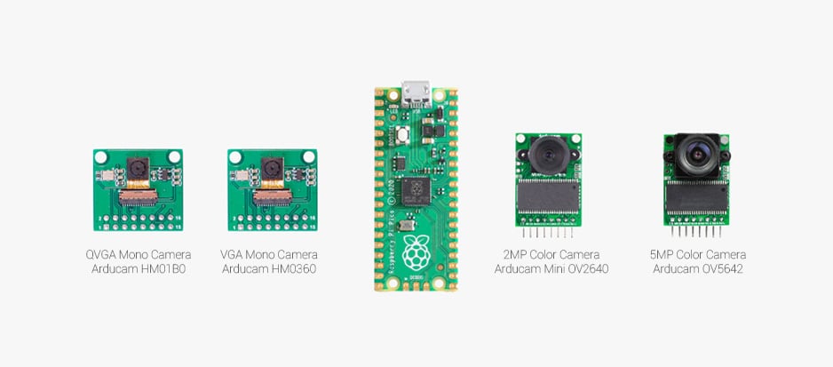
 distant monolith
Hey could someone explain me what an interrupt vector table is, and what it consists of. Ive read alot on the internet but I still cant understand it properly
umbral sable
distant monolith
Hey could someone explain me what an interrupt vector table is, and what it cons...
When an interrupt fires, the CPU stops what it's doing and wants to run code to respond to the interrupt condition. The vector table is a list of function addresses that it should use. So if interrupt #3 fires, the CPU looks at the third entry in the table, and runs the function at that address in memory. When the function returns, the CPU resumes executing the code from before the interrupt happened.
civic rune
2 audio issues:
-
The audio out of my pi is very weak, whereas it wasn't earlier is it worth it to try a new pi?
-
pygamedoesn't seem to output to the audiojack. I have checkedraspi-configand made sure that the audiojack was the output.
in previous attempts pygame worked fine
audio is set to full
ahhh ok one problem fixed, VLC was set low
civic rune
pygame.mixer.music.get_busy() also returns 0 when I tell pygame to play music
civic rune
I think I found more relevant errors, when instead of using
pygame.mixer.init()
pygame.mixer.music.load("/home/pi/Desktop/MySong.mp3")
pygame.mixer.music.play()
I use
pygame.mixer.init()
sound = pygame.mixer.Sound("/home/pi/Desktop/MySong.mp3")
I get the error "Unable to open file /home/pi/Desktop/MySong.mp3
 chrome turret
hey, quick question: I wonder if you could transfer data via a serial connection on the 2 data pins on the usb c connector, I checked the schematics and it seems possible by modifying the pi config but I would like to know if someone did it

its for a raspberry pi 4b+
its the two pins named UUSB_D_P and UUSB_D_N
turbid rivet
Theoretically, the lines can be used for data, but I don't know of a way to configure them for specifically serial data.
Here's an example of the Pi4 as an OTG device, though the thread lists a plethora of reasons why you shouldn't rely on this functionality too much. https://forums.raspberrypi.com/viewtopic.php?f=63&t=243966
civic rune
how can I check which version of pygame I have installed?
ah gosh, I upgraded pygame and seem to have broken it
 tidal crest
Hi,
I already asked in the circuitpython channel for help for my project and they thought I 'd be right here. It’d be great if anyone had an idea how to control the SPI-CAN module (MCP2515) via python with the raspi? I already tried a lot, but nothing worked!

 hard pike
@tidal crest usually you would write a driver library to interface with the device
You could do this with circuitpython blinka, write a library that uses circuitpython busio/spi_bus device and set up read and write commands following the outlines commands in the device data sheet
But someone has probably done the heavy lifting for that chip somewhere
tidal crest
Yeah I did the instructions from following website: https://forums.raspberrypi.com/viewtopic.php?t=141052
they used the library can
But I can't send any information
hard pike
Do you have a CAN transceiver ?
tidal crest
 hard pike
Like the MCP2562
tidal crest
It's all on the module
hard pike
Okay good
tidal crest
(TJA1050)
hard pike
Do you have anything on the other end of the can bus?
tidal crest
Yes a servo
hard pike
Okay
tidal crest
It's a special Servo that works on CAN
I already successfully wrote a test script with Arduino IDE
hard pike
Okay. Hmm
tidal crest
(so I tested the whole Hardware already with the Arduino)
hard pike
How far in the tutorial did you get?
tidal crest
till the end
hard pike
Okay. Did the can interface show up in the network configuration?
tidal crest
Yes
hard pike
Do you have a logic analyzer?
tidal crest
No, unfortunately not
hard pike
Dang, I was going to say if you did we could look at the signal
Though… we might still be able to kind of analyze the signal..
tidal crest
That would be kinda progress😂
hard pike

GitHub
Logic Analyzer, for Arduino, AVR, ESP8266 and STM32 with a very nice working processing interface, you could run it also on any Android device. - GitHub - aster94/logic-analyzer: Logic Analyzer, fo...
If you have a spare micro, you could put this on a Uno or something and kind of analyze the can bus
tidal crest
Therefore I need a minute to download the Arduino IDE on the raspi right?
hard pike
Not unless you have it on another computer
hard pike
Anyway, if you have an idea of what your signal should look like, you can analyze the can bus and see if it looks like it’s supposed to.
tidal crest
Next I need to figure out how the sketch works ;
hard pike
Well, from what I gather is it polls the input puns and uses interrupts on each pin for data acquisition.
Takes the data it acquired and sends it to the serial interface which is the other program they discuss in the readme
tidal crest
So, then I uploaded UNO.ino on the Arduino UNO
hard pike
Yeah
tidal crest
But how to I get the graphical interface
hard pike
And then run the computer portion
tidal crest
*do
hard pike
there’s a computer interface directory
tidal crest
yes
hard pike
Okay search in the start menu for processing.exe
From the computer interface directory
tidal crest
there's only processing.pde
hard pike
Okay, hold on. What happens if you hit compile on the processing.pde file?
Look like you need this
Processing
Processing is available for Linux, Mac OS X, and Windows. Select your choice to download the software below.
hard pike
Should just extract the files and install
tidal crest
 hard pike
Okay, open the PDE file in there
Then change the board and serial port to your Uno
Then run
tidal crest
but before that shouldn't I upload the SPI-CAN file I wrote?
instead of the UNO.ino file
hard pike
Well, are you sending the CAN data from the raspberry pi?
tidal crest
No I thought you'd like to test it via the Arduino where it already works
hard pike
Do you have two Uno?
Because you would need two if you want to test the Arduino output to get a baseline for testing on raspberry pi
tidal crest
Could we go to a voice channel so that I can explain you everything, think it would be easier
hard pike
Unfortunately I’m helping between doing things at work
But anyway, one Uno needs to run the logic analyzer code to send data to the processing.pde program
If you want to test what works on Arduino already, you would need a second Uno or Arduino that can drive the can bus
tidal crest
No I think you misunderstood me...
It already works on the Arduino, but I'd like to control it via the GPIOs on the Raspberry
tidal crest
Yes
hard pike
Okay, you need to analyze the successful system to know if your rpi is driving the can bus properly. Which is why I am saying two boards to run Arduino code. One to run the analyzer, one to drive your can controller
Take the can bus lines and put them into the input pins the analyzer lists
Send your commands for your servo, screen cap the results from the graphical interface, then rinse repeat doing the same thing but from the RPi
tidal crest
So I should connect the H and L (Ios)to the second arduino
hard pike
Right
tidal crest
Ah ok sry
hard pike
You want to know the known good signal

 tidal crest
 hard pike
Okay that seems normal
tidal crest
I'm not that familiar with CAN but I think it should be right because it works 😉
hard pike
Sure, if it’s working then I would assume this is a good baseline
tidal crest
I don't know how CAN-data transmission works in detail
hard pike
I believe can is based on rs485
Welcome to the second post in this series on the controller area network (CAN), which is increasingly being used in industrial applications. In this post,...
tidal crest
So thus we measure Vdif?
hard pike
Well, the transceiver will
tidal crest
whatsoever, maybe we could fix my problem with the raspberry
hard pike
We can at least see if we’re getting the right data at least
tidal crest


...obviously it's different, but there's another problem which always occurs; here's the error message:
hard pike
Oh that’s peculiar
Have you tried googling the error at all?

Stack Overflow
I'm running a program with two CAN channels (using TowerTech CAN Cape TT3201).
The two channels are can0 (500k) and can1 (125k). The can0 channels works perfectly but can1 runs a write:No buffer ...
tidal crest
Now the program has no Error anymore
but I still don't know how to send the right information so that I get the right output
in C++(Arduino Ide) the code looks like that:
TxFrame.can_id = 0x001; // Can-ID
TxFrame.can_dlc = 5; // DataLengthCode
TxFrame.data[0] = 0x77; // 'w'
TxFrame.data[1] = 0x00; // Servo-ID
TxFrame.data[2] = 0x1E; // PosNew
TxFrame.data[3] = Pos & 0xFF; // Position - LSB
TxFrame.data[4] = Pos >> 8; // Position - MSB
mcp2515.sendMessage(&TxFrame);
In python with CAN library:
import time
import RPi.GPIO as GPIO
import can
bustype = 'socketcan'
channel = 'can0'
bus = can.interface.Bus(channel=channel, bustype=bustype,bitrate=1000000)
msg = can.Message(arbitration_id=0x001, dlc=5, data=[0x77, 0x00, 0x1E, 2000 & 0xFF, 2000 >> 8], is_extended_id=False)
msg1 = can.Message(arbitration_id=0x001, dlc=5, data=[0x77, 0x00, 0x1E, 4000 & 0xFF, 4000 >> 8], is_extended_id=False)
try:
while True:
bus.send(msg)
time.sleep(1)
bus.send(msg1)
time.sleep(1)
# for msg in bus:
# print(msg.data)
except KeyboardInterrupt:
GPIO.cleanup()
print("Finished")
tidal crest
void loop()
{
//CanServoWriteSingleValue(0x54, 0x3FF);
CanServoSetPosition(0);
delay(1000);
CanServoWriteSingleValue(0x54, 0x100);
CanServoSetPosition(1024);
delay(1000);
CanServoSetPosition(2048);
delay(1000);
CanServoSetPosition(3096);
delay(1000);
CanServoSetPosition(4191);
delay(1000);
}
1024, 2048
...
hard pike
Gotcha
tidal crest
Oh, I will write the same positions in python and then look how the signal is doing but it then still won't work
the problem is that I have no clue how to convert the commands from Arduino Ide right to python, because the library is different
hard pike
Can you create a loop where in place of the 4000 you put a hex variable equal to your position values. Then do your bitwise operations
So some 8bit unsigned int or a buffer even
tidal crest
I've no idea what you mean, shall I replace the decimal values to hex?
hard pike
Yeah. Convert your positions into hex
tidal crest
like that:
msg = can.Message(arbitration_id=0x001, dlc=5, data=[0x77, 0x00, 0x1E, 0x400 & 0xFF, 1024 >> 8], is_extended_id=False)
msg1 = can.Message(arbitration_id=0x001, dlc=5, data=[0x77, 0x00, 0x1E, 0x800 & 0xFF, 2048 >> 8], is_extended_id=False)
msg2 = can.Message(arbitration_id=0x001, dlc=5, data=[0x77, 0x00, 0x1E, 0xC18 & 0xFF, 3096 >> 8], is_extended_id=False)
msg3 = can.Message(arbitration_id=0x001, dlc=5, data=[0x77, 0x00, 0x1E, 0x105F & 0xFF, 4191 >> 8], is_extended_id=False)
nothing really different:
 tidal crest
if_nametoindex: No such device
hard pike
Can you create a new test file and try this?
import can

bustype = 'socketcan'
channel = 'vcan0'

def producer(id):
    """:param id: Spam the bus with messages including the data id."""
    bus = can.interface.Bus(channel=channel, bustype=bustype)
    for i in range(10):
        msg = can.Message(arbitration_id=0xc0ffee, data=[id, i, 0, 1, 3, 1, 4, 1], is_extended_id=False)
        bus.send(msg)

    time.sleep(1)

producer(10)```This is an example from the socketcan docs
hard pike
What does the analyzer show?
tidal crest

I don't if it's the right data
there's always a signal on pin 9 even though I stopped my program
tidal crest
0xDEADBEEF
hard pike
Yeah
tidal crest
do you know anyone who knows anything about the can library and how to use it right
civic rune
Trying to figure out what I did to pygame and to avoid nuking/reloading my pi. Pygame suddenly stopped playing music out of the headphone jack. I checked raspi-config and made sure headphones were the output. I confirmed that VLC player and the vlc library are capable of playing sounds.
I tried updating pygame with pip3 pygame --upgrade but that led to another error related to libSDL2 when I tried to call pygame.mixer.init(). A user in a different discord suggested I run sudo apt-get install python3-sdl2
Now I am able to run
import pygame
pygame.mixer.init()
pygame.mixer.music.load("/home/pi/Desktop/mysong.mp3")
but get an error when I run
pygame.mixer.music.play()
the error is
Note: Illegal Audio-MPEG-Header 0xffe50141 at offset 35696
Note: Trying to resync
Note Skipped 1024 bytes in input
[src/libmpg123/parse.c:1273] error: giving up resync after 1024 bytes - your stream is not nice
Traceback (most recent call last):
  File "<pyshell>", line 1 in <module>
pygame.error: mpg123_seek: Unable to set up output format! (code 1)
am I best off nuking the pi and starting from scratch?
civic rune
for posterity, I solved this by converting my song from .mp3 to .ogg. I don't know why pygame would suddenly stop working with .mp3s but I guess it's finicky
 zealous seal
civic rune
for posterity, I solved this by converting my song from .mp3 to .ogg. I don't kn...
zealous seal
civic rune
for posterity, I solved this by converting my song from .mp3 to .ogg. I don't kn...
Was the mp3 one you converted yourself? Based on the message, whatever converter/encoder your using is probably just not to spec and wrote a corrupted header (it could also be from a service that does something sketchy intentional for copyright protection unfortunately) - you could try using a different program to convert to mp3. Pygame could also be using an mp3 decoder that doesn't support some features of the mp3 spec - but its probably not worth digging too much in to.
civic rune
yeah I figured something was wrong with the file format, but for whatever reason(s) it worked before? IDK, not looking a gift .ogg in the mouth
civic rune
my pi doesn't seem to boot (nothing on the monitor) but when I plug the SD card into my PC it shows the boot drive as normal. Is this an instance where I need to re-flash the SD card?
 humble marsh
civic rune
my pi doesn't seem to boot (nothing on the monitor) but when I plug the SD card ...
humble marsh
civic rune
my pi doesn't seem to boot (nothing on the monitor) but when I plug the SD card ...
which kind of pi? do you get blinky lights as if it's trying to boot
humble marsh
pi zero can appear dead with a bad SD card, but it's not really
civic rune
I just turned the power on and the act LED is blinking
humble marsh
do you have any other Pi SD cards to try? If you don't care about what's on it, yes I would say reformat and update. But if it blinks and eventually one of the lights stays on, it may still be up, but not doing video for some reason. You could try ssh'ing into it
 magic lodge
Hello, I am working on an IOT project using the adafruit sgp30 sensor with a Raspberry Pi 4B. I tried out the example code and like it says, after some warm up time, the eCO2 and TVOC values start fluctuating. I am new to using cron jobs in Linux. My intent is to store values in a database and get them displayed on a web browser using flask. My question is: Is there a way I can use the example code but without a while loop and using cron jobs to display data every 20 minutes for example, or would that be an issue because of the warm up time ?
civic rune
aaaaaand it's working again for no reason. Apparently I just had to scare the SD card into thinking I was going to re-format it
humble marsh
magic lodge
Hello, I am working on an IOT project using the adafruit sgp30 sensor with a Ras...
If the SGP30 remains powered, then I think that may be fine. I'm not familiar with what the SGP30 does when it's not being queried for a while. I would suggest you just try it. You don't have to learn cron jobs in detail right now: you could just write a shell script that invokes your python program every 20 minutes and sleeps in between looping around
magic lodge
humble marsh
If the SGP30 remains powered, then I think that may be fine. I'm not familiar wi...
Okay thank you very much, I am going to try that. Hopefully the fact that it is not queried for a while is not an issue.
humble marsh
magic lodge
Okay thank you very much, I am going to try that. Hopefully the fact that it is ...
if it is, you may need to take readings for a while until it stabilizes again
magic lodge
Yes, thank you for the tip. I will try this out as soon as I get the chance to.
 lost wolf
civic rune
what kind of SD card do I need for a pi? It's microsd right?
lost wolf
civic rune
what kind of SD card do I need for a pi? It's microsd right?
XC is capacity related. So it's up to you what size you want. MicroSD is the form factor.
civic rune
perfect thanks, thats what I thought. Apparently I was in the wrong place in digikey, as a google search brought me the right thing
zealous seal
Does anyone know of any compact CM4 compute carriers that have all 4 CSI lanes?
 spark lake
Im trying to run a single command on startup on raspbian - I've tried rc.local, systemd, and crontab but none of them seem to work. the command itself is just to start a python script in tmux. Anyone know why this might not be working or might have an alternative solution?
civic rune
Watching, I have to deal with this soon
opaque wagon
systemd is the preferred solution - a quick search on google will show you how to do it
https://www.howtogeek.com/687970/how-to-run-a-linux-program-at-startup-with-systemd/ is a good one

How-To Geek
Need to launch a Linux program at boot? The systemd software provides a way to do it on any Linux distro with systemd—which is most of them these days, including Ubuntu. We’ll walk you through the process of creating an integrated service—and it even talks to the journal.
steady rose
@spark lake and another guide here:
https://learn.adafruit.com/running-programs-automatically-on-your-tiny-computer
spark lake
steady rose
<@!146151306216734720> and another guide here:
<https://learn.adafruit.com/runni...
ill read through that guide thanks - I already love the first image
spark lake
steady rose
<@!146151306216734720> and another guide here:
<https://learn.adafruit.com/runni...
Parts of that tutorial is telling me to copy a file called skeleton but I see no file named such
steady rose
i think that's in the sysv init section?
skip it. use systemd.
the guide shows two different methods - sysv and systemd
spark lake
I tried systemd already didnt work
steady rose
what happened?
spark lake
when using sudo systemctl start myfirst literally nothing
steady rose
no error messages or anything? just returned right back to prompt?
spark lake
yep
i already deleted the file but im going to follow the tutorial @opaque wagon posted and try that
steady rose
sudo systemctl status myfirst
what does that show?
also, can try going through guide and using the mouse.py example. see if you can get it to work as shown. as a basic test.
opaque wagon
spark lake
when using `sudo systemctl start myfirst` literally nothing
it starts it in the background - use the status command cater said which will show the last couple lines of output and the status (duh) of the program, like whether it's running or not
nothing is supposed to be printed when you start a service
spark lake
steady rose
`sudo systemctl status myfirst`
lemme post a little context real quick- Here's the start.sh file-
#!/bin/sh

cd /home/pi/bart-map
tmux new-session -d -s bart-map 'python3 ~/bart-map/main.py'
``` And the result of status -
```bash
pi@BART-MAP-PROJECT:~ $ sudo systemctl start myfirst
pi@BART-MAP-PROJECT:~ $ sudo systemctl status myfirst
● myfirst.service - Bart Map Project
   Loaded: loaded (/etc/systemd/system/myfirst.service; disabled; vendor preset: enabled)
   Active: inactive (dead)

Oct 26 16:16:53 BART-MAP-PROJECT systemd[1]: Started Bart Map Project.
Oct 26 16:16:53 BART-MAP-PROJECT start.sh[829]: Starting...
Oct 26 16:16:53 BART-MAP-PROJECT start.sh[829]: Ending...
Oct 26 16:16:53 BART-MAP-PROJECT systemd[1]: myfirst.service: Succeeded.
Oct 26 16:17:36 BART-MAP-PROJECT systemd[1]: Started Bart Map Project.
Oct 26 16:17:36 BART-MAP-PROJECT start.sh[858]: Starting...
Oct 26 16:17:36 BART-MAP-PROJECT start.sh[858]: Ending...
Oct 26 16:17:36 BART-MAP-PROJECT systemd[1]: myfirst.service: Succeeded.
Oct 26 16:19:20 BART-MAP-PROJECT systemd[1]: Started Bart Map Project.
Oct 26 16:19:20 BART-MAP-PROJECT systemd[1]: myfirst.service: Succeeded.
pi@BART-MAP-PROJECT:~ $
that means the script successfully ran
spark lake
the Starting... and Ending... are from a previous version of the start.sh file where I used echo Starting...
opaque wagon
then you have to do something like nvm read your message wrongsudo systemctl daemon-reload to "refresh" everything
opaque wagon
everything appears to be working just fine - what's the problem??
if you reboot the pi it should run
spark lake
Oh I assumed it would run it once on start - I didnt know I'd have to restart it to test
opaque wagon
no, it will run it on start as well
spark lake
i mean on systemctl start, because if it suppsed to run it then it is not
opaque wagon
it will run once the pi turns on, whether from power on reboot the system
everytime you want to start the script you would run the start command
if the script is still running, you can type stop i think
(like sudo systemctl stop myfirst or something)
opaque wagon
it is
spark lake
there's no tmux shell being opened
opaque wagon
hmmmm
that might be tmux's fault??? or mayube the tmux thing ends when the command ends
according to the status commands everything seems to be fine
spark lake
alright I just tried running the start.sh without systemd and it didnt work
so looks like systemd is working now I have a different issue
pi@BART-MAP-PROJECT:~/bart-map $ ./start.sh
Ive been started
cd /home/pi/bart-map
tmux new-session -d -s bart-map python3 /home/pi/bart-map/main.py
echo Ive been ended
pi@BART-MAP-PROJECT:~/bart-map $ tmux attach
no sessions
pi@BART-MAP-PROJECT:~/bart-map $
@opaque wagon alright when I run the start.sh file it does not work
but if I run the command myself it works fine
opaque wagon
i'm not that familiar with tmux - but why do you want to create a session? can't you just have the service file run the command python3 /home/pi/bart-map/main.py?
spark lake
so that if it errors out (because this python script is designed to run forever) I can see the error by just going into tmux
unless there is another way to do that
opaque wagon
wouldn't it be easier to create a log file?
spark lake
Honestly I've never even thought about that
opaque wagon
(and probably auto-trim / delete the log file)
spark lake
I used tmux all the time for other stuff
opaque wagon
tmux is nice tho
opaque wagon
systemd can auto-restart the file if it returns a non-zero status code (error)
Stack Overflow
I am running a bash script that creates a log file for the execution of the command
I use the following
Command1 >> log_file
Command2 >> log_file
This only sends the standard output ...
^^ redirect output from script
spark lake
opaque wagon
^^ redirect output from script
so something like this then?
#!/bin/sh

echo Ive been started
cd /home/pi/bart-map
python3 /home/pi/main.py >> log.txt 2>&1
echo Ive been ended
looks good to me
if you run the script from the terminal (./start.sh or whatever the file is called) do you get a new text file called log.txt in /home/pi/bart-map?
spark lake
no file was made
civic rune
what does
#!/bin/sh
do?
spark lake
look up shebang
civic rune
Ah ok
spark lake
opaque wagon
if you run the script from the terminal (`./start.sh` or whatever the file is ca...
none was made - any ideas?
spark lake
it has a single print near the beginning
opaque wagon
no file in your current directory? or in /home/pi/bart-map?
spark lake
 spark lake
a log file is made
spark lake
heck if i know
opaque wagon
i'm sorry, it's getting late for me - i need to get off
good luck
 spark ether
My first custom neopixel script is having some weird trouble. It's essentially the same as the "simple test" script, but I'm trying to set the colors of the Neopixel ring based on sensor data.
Currently, I read sensor data into a Pandas dataFrame where the number of columns is truncated to be = to num_pixels. I then take the mean of each column and try to use that to determine which color each pixel should be. This operation replaces rainbow_cycle() as the function that sets colors.
I've been through several versions of this. Currently my work in progress looks like this:
def my_led(data):
# set all pixels to a color
pixels.fill((255, 0, 0))
pixels.show()
# Change pixels colors based on data in columns
for col in data.columns:
index = data.columns.get_loc(col)+1
mean_value = data[col].mean()
print(index)
if mean_value < 0 and index <= num_pixels:
pixels[index-1] = wheel(255)
pixels.show()
elif mean_value > 0 and index <= num_pixels:
pixels[index-1] = wheel(100)
pixels.show()
The main problem is that it just doesn't seem to do anything with the Neopixel, even if there is no error. Additionally, if I remove the "+1" at the end of "data.columns.get_loc(col)+1" and the "-1" in "pixels[index-1]" then it raises an Indexerror. It's weird because the "+1" and "-1" should cancel each other out, so I don't understand how this avoids the IndexError... or why it would happen in the first place since I make sure that index is never used if it's greater than num_pixels, which it shouldn't be in the first place.
Any help is greatly appreciated.
I would like to have used code block formatting on that for you but I haven’t learned that trick yet in Discord for iOS
civic rune
Don't have time to read thru the whole thing but I think raspis have trouble with neopixels due to the very precise timing required
pis are really fast but the OS/background stuff can cause you to miss firing a pin at the right time
spark ether
Ok thanks. The simple test itself works fine tho so I think it may be a code issue. I’m totally new to Neopixel so it’s a little weird to me.
steady rose
try printing both mean and index
print(index, mean)
pixel index is 0 based, 0=first pixel N-1=the Nth pixel, etc.
 tired marsh
note that pixels are indexed starting with 0, you testing index <= num_pixels is why pixels[index-1] avoids an error. By removing the -1, cases where index is out of bounds are not skipped and lead to a crash
spark ether
When I do that it shows me the means and the indexes and if there is an IndexError it always prints up to the last one before the error. If I reduce num_pixels it doesn’t change the behavior.
I see what you’re saying but dataFrames are also zero indexed and the +1 and -1 should be cancelling out I think
steady rose
if you're getting an index error with an index that is in range, then something else is happening
steady rose
neither logic block may be running
which is why printing both values prior could help
spark ether
Yea I have a version with a print statement for every interesting line
pixels.fill(255,0,0) should make it all red before anything else has a chance to go wrong correct?
tired marsh
if num_pixel is how you setup the neopixels too, changing it won't do anything, you need a < instead of <= if you remove the -1
spark ether
Yea ok let me try tweaking that
tired marsh
isn't it pixels.fill((255,0,0)) ?
tired marsh
oh but it's in your code
spark ether
I thought you were telling me I needed more parentheses, I see what you’re saying
steady rose
def my_led(data):
    # set all pixels to a color
    pixels.fill((255, 0, 0))
    pixels.show()
    # Change pixels colors based on data in columns
    for col in data.columns:
        index = data.columns.get_loc(col)
        mean_value = data[col].mean()
        print(col, mean_value, index)
        pixels[index] = wheel(255) if mean_value < 0 else wheel(100)
        pixels.show()
^^ bare bones, with no index checking
spark ether
Thanks @steady rose I will have check that out as soon as I’m out of work for the day
solemn finch
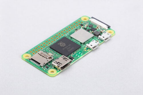
Announcing the successor to the groundbreaking Raspberry Pi Zero: the $15 Raspberry Pi Zero 2 W, built around our own RP3A0 System-in-Package
distant monolith
Hello, for a school project I have to use a ping of death to crash something, but the newer systems are protected against it, do u guys think I could try it on a raspberry pi?
 rocky flare
@distant monolith Yes, but the latest OS my also be protected against it. So you'll have to look to see if an older version of their OS is still available. May still be a struggle finding an OS that still has this issue.
 zinc jackal
Install Win95 on something. 😛
rocky flare
@distant monolith Do you need to demonstrate it? If not just researching the issue and writing about it's cause and how it was found should be enough.
 drowsy stream
@turbid rivet I need help saving and compering fingerprint data on a database using fingerprint sensor model R307 and a raspberry pi 4. thanks
To be more descriptive. I wanted to setup a fingerprint authentication and when users register i wanted their data to be saved on a database (MongoDB) and when they try to login i want to compare the fingerprint data saved on MongoDB with the snapshot of their fingerprints. can any one please help me?
By the way i am using a library called PyFingerprint link: https://github.com/bastianraschke/pyfingerprint
GitHub
Python library for ZhianTec fingerprint sensors (e.g. ZFM-20, ZFM-60) - GitHub - bastianraschke/pyfingerprint: Python library for ZhianTec fingerprint sensors (e.g. ZFM-20, ZFM-60)
turbid rivet
drowsy stream
To be more descriptive. I wanted to setup a fingerprint authentication and when ...
What exactly do you need help with?
drowsy stream
how to get the fingerprint image from the sensor and store it in database and then when a user tries to authenticate his/her fingerprint data is fetched from the database and compared with the current snapshot of their fingerprint
turbid rivet
drowsy stream
how to get the fingerprint image from the sensor and store it in database and th...
https://robu.in/wp-content/uploads/2018/05/r307-fingerprint-module-user-manual.pdf
I don't have personal experience with this device, but this manual does show that the module has a command to upload/download images. The command itself is around page 14, and the image buffer it uses is described on page 4.
The database, on the other hand, is something I have even less experience with, but given how to upload and download fingerprint images, I'm sure the database aspect has far more resources available online.
civic rune
do I need a 5.1V power supply for a rasberry pi?
lost wolf
They'll run on less than the recommended, but can have issues. If you run into issues, blame a smaller power supply before banging your head against other possibilities.
civic rune
hmm shoot, all the power supplies that fit my needs are very expensive
lost wolf
What do you need and what is "very expensive"?
civic rune

I need a power supply that takes AC input from a cable like this one
So I can seal off the inside of the enclosure. I found a cheapish 5V one, but I think I need 5.1V
Expensive is 30 dollars+
civic rune
interesting, this one doesn't have an AC ground
Order today, ships today. TMPW 25-105-J – Enclosed AC DC Converters 1 Output 5.1V - - - 90 ~ 305 VAC, 100 ~ 250 VDC Input from Traco Power. Pricing and Availability on millions of electronic components from Digi-Key Electronics.
lost wolf
I'm not sure that .1V makes enough of a difference, tbh. But I don't know for sure.
civic rune
Hmm, I can just order a 5.1V one to be safe
lost wolf
When I said they work at less than recommended, I meant like 3V vs 5V kind of "less".
But yeah better to be safe.
Especially when you want to seal it and forget it.
civic rune
maybe the rest of this conversation is better off in #help-with-projects as it's about AC cables. Thanks for your help!
lost wolf
You're welcome!
faint sparrow
The RPi4 ran at about 1.4 Amps on the current limiter of a Korad KD3005D including some extra circuitry. Idled at 800 mA. Ran way down on voltage (don't remember the number - 4.4 VDC seems likely above it).
4.9 VDC @ 2.5A should be adequate unless your USB-connected device draws a lot of current.
civic rune
Hmm, it seems then that I could get by with a 3A PSU if I couldn't use the official adapter?
solemn finch
in stock now: https://www.adafruit.com/product/5291

Raspberry Pi Zero 2 W is the latest product in Raspberry Pi's most affordable range of single-board computers. The successor to the breakthrough Raspberry Pi Zero W, Raspberry Pi Zero 2 ...
 raw solar
Ordering!!!
On Pi power supplies: I almost exclusively use 5V adapters, and some of the ones running on 5V have an ever-present lightning bolt icon [low voltage], but I've never had crashes or anything because of it [or at least I don't notice any problems]
raw solar
raw solar
Ordering!!!
Crap, out of stock already DX
civic rune
raw solar
On Pi power supplies: I almost exclusively use 5V adapters, and some of the ones...
I have this same issue
 wraith tapir
Hi 🙂 Does anyone here know how I can best separate NeoPixels into pre defined areas.
I have 6 different temperature sensors and I want to basically have pixel x -y respond to temperature changes in the sensor in that "area"
I hope this is the right channel to ask this. I have most of the code written but I am clueless on how to best do this part since I am very new with python 😦
civic rune
You can do that with list slicing I think?
I'm typing from the drive thru so I can't give a lot of details
Gotta focus on unsafe driving practices
wraith tapir
No please stay safe!
wraith tapir
The reading out the sensor data and taking an average of two works
def calcAverage1(sens1, sens2):
    return ((sens1+sens2)/2)

def calcAverage2(sens3, sens4):
    return ((sens3+sens4)/2)

def calcAverage3(sens5, sens6):
    return ((sens5+sens6)/2)
I have no idea how to approach having positions pre defined
I know how to make the whole strip change colors accordingly
But I want calcAverage1 to only change the pixels 0-43 (for example)
tired marsh
you can do something like:
pixels[0:44] = [color] * 44
I made a beautiful drawing:
 tired marsh
(I had a off-by-one error of course)
wraith tapir
Oh I should mention I am using the rpi-ws281x library for this
raw solar
civic rune
I have this same issue
I only really consider it a problem if it breaks something XD
tired marsh
ah I don't know that library
wraith tapir
I think its just the ported arduino neopixel library
I would post the whole code here but it's a bit long I don't want to spam or anything (its also really bad)
tired marsh
you can upload it with +
wraith tapir
I already fried one Pi with this project 
But thats an electronics issue I solved :p
tired marsh
it looks something like this:
START1 = 0
SIZE1 = 44

def setStrip1(color):
    for i in range(START1, SIZE1):
        strip.setPixelColor(i, color)
    strip.show()
if I'm looking at the right library
tired marsh
yeah, if the pixels are aligned with the sensors I would define ranges per sensors like this:
RANGE1 = range(0,44)
RANGE2 = range(44,80)
etc.
and then in the loop
color = something(calcAverage1())
for pixelNum in RANGE1:
  strip.setPixelColor(pixelNum, color)
color = something(calcAverage2())
for pixelNum in RANGE2:
  strip.setPixelColor(pixelNum, color)
...
strip.show()
I think you want that ?
def calcAverage1():
    return ((sens1.get_temperature()+sens2.get_temperature())/2)
you want different colors for each sensor or the same temperature is the same color ?
 tired marsh
some way to compute the temperature would be:
COLD_AS_ICE = (0, 100, 255)
BELOW_10_C = (0, 200, 255)
...
SUPERHIGHTEMP = (255,255,255)

def temperatureColor(temperature):
  if temperature < 0:
    return COLD_AS_ICE
  if temperature < 10:
    return BELOW_10_C
  ...
  return SUPERHIGHTEMP
you could table it in a list and loop through it
colors = [
  (0, (0, 100, 255)), # that's below 0 C
  (10, (0, 200, 255)),
  ...
]
SUPERHIGHTEMP = (255,255,255) # default color

def temperatureColor(temperature):
  for temp, color in colors:
    if temperature <= temp:
      return color
  return SUPERHIGHTEMP
What does the 0 and 10 in front of the colors do exactly?
tired marsh
it's the temperature limit: if T below that it's that color
wraith tapir
ooo
tired marsh
and so the example above would become
while True:
  color = temperatureColor(calcAverage1())
  for pixelNum in RANGE1:
    strip.setPixelColor(pixelNum, color)
  color = temperatureColor(calcAverage2())
  for pixelNum in RANGE2:
    strip.setPixelColor(pixelNum, color)
  ...
  strip.show()
  time.sleep(DELAY) # don't update too often
note that DS18B20 takes some time to get the temperature, I don't know how you can parallelize the temperature reading with the library you are using
wraith tapir
Sorry if I am slow at responding I am trying to wrap my head around this 🙂
What do you mean parallelize?
tired marsh
I don't know how the library you use works but reading the temperature takes 750ms with the default 12 bit precision, so if the library waits that long it might make for a slow loop, but it might not be an issue for your use.
wraith tapir
Ah that should be fine. I dont really need perfect accuracy or anything like that
Just semi functional code as a proof of concept. I will try implementing your help :3
It always takes me a good while to understand python code thats not very basic. I have a bit of a learning disability. This was massive help already tho 
Ah this is a silly question but when I do
START1 = 0
SIZE1 = 50
And then
START2 = X
SIZE2 = 50
What is X gonna be?
I assume 50 for START2? Because I end up at 49 when I start counting from 0
tired marsh
maybe that's better, just reference the start and end, because the last in a range() is excluded, you just start where the previous ends:
RANGE1 = range(0,44)
RANGE2 = range(44,80)
RANGE3 = range(80,NUM_LEDS)
and maybe call them START1 = 0, START2 = 44, START3 = 80
that way if you change START2 you don't forget to change it in both places
wraith tapir
RANGE1 = range(0,44)
RANGE2 = range(44,80)
RANGE3 = range(80,NUM_LEDS)

def setStrip1(color):
    for i in range(RANGE1):
        strip.setPixelColor(i, color)
    strip.show()
Like this?

tired marsh
that should do it
wraith tapir
Awesome 
wraith tapir
Can I do this?
        while True:
            print(calcAverage1())
            color = temperatureColor(calcAverage1())
            for pixelNum in RANGE1:
                strip.setPixelColor(pixelNum, color)
I would like to print the return value of the function before I use it
I think I am missing a : in this
tired marsh
better to do:
temperature = calcAverage1()
print(temperature)
color = temperatureColor(temperature)
remember that each call of calcAverage1() likely takes 1.5 seconds (750ms per sensor), so only call it once, and save the result in a variable
wraith tapir
awesome!
thank you so so much for all the help. I can write simple network scripts but everything falls apart as soon as I have to work with indexes and whatnot

Appreciate the help
civic rune
weirdness, my pi wouldn't boot (nothing on the ACT LED) so I unplugged literally everything from it. Now the ACT LED is going on and off but nothing is displaying on my monitor. Do I need to reflash the SD?
civic rune
hmmm my only option right now is the one SD card I have. I guess it's re-flash time
faint sparrow
Well try another PSU if you have one
civic rune
only have the one, it's the official one and it was working fine before
faint sparrow
That only applies well if you aren't asking in a forum. ;)
'it worked before' isn't often relevant
(at this level of inquiry)
The Pi's are definitely known to have issues damaging the stored image on the SD card.
Haven't had it happen yet.
I have a copy of the entire SD card on my computer's hard disk (using dd in Linux).
civic rune
I decided to just reflash and see what happens. I'll have to track down the problem later
faint sparrow
Theoretically I can restore it to the state it was in when I image'd it.
civic rune
that's my plan for the future
faint sparrow
Reflash is a cheap test if you don't mind losing what used to be on it.
You can also try to image the card prior to reflashing.
I try real hard to get at least two of 'everything' so that I have that one extra one left, to play with.
civic rune
I had two, but something happened to the spare and it started getting hot when plugged in. Enough to leave a small burn
faint sparrow
rut roh
The problem with the Pi is it's too inexpensive to get it repaired. But too expensive to .. I don't know, waste it, I guess.
So you can I would expect fry .. a second SD card .. in a 'bad Pi' I'd think.
Similarly, a bad SD could fry Pi after Pi after Pi ;)
 dark rivet
Anyone know why the screen command might not interface with a pi zero via serial cable? (Linux)
Screen just keeps terminating and I'm not getting any output from the pi
dark rivet
Works over windows with putty for some reason
Nevermind, manjaro just sucks. Thank you for reading
humble marsh
dark rivet
Works over windows with putty for some reason
You often need to give yourself permission to use the serial ports. To test if you need to do that, try running screen with sudo. If that works, then add your user to the group used for the /dev/tty* devices. Example here: https://learn.adafruit.com/welcome-to-circuitpython/advanced-serial-console-on-linux
dark rivet
Running with/without sudo did not seem to change anything. But switching to my laptop with endeavourOS worked just fine.
 wanton holly
can anyone suggest a humidity sensor for a raspi ? SPI or I2C i dont know , good enough to measure humidity in house accurately and not cost a million dollars
steady rose
checkout the options here:
https://www.adafruit.com/category/66
and this is worth reading too, a PSA of sorts:
https://learn.adafruit.com/modern-replacements-for-dht11-dht22-sensors
wanton holly
cool thanks
 novel mist
Hey there!
What is the easiest way to find out my ip adress in python on a raspberry?
i found a lot of way online, but some doesnt work some just give me 127.0.1.1
i think i found it
from subprocess import check_output
print check_output(['hostname', '-I'])
this is only 2 lines
steady rose
that'll work. looks like python2 syntax though, based on the print statement
print(check_output(['hostname', '-I']).strip().decode())
maybe?
 hard pine
anyone good with LED matrix stuff? i'm using this https://www.adafruit.com/product/2278 64x32 matrix with this https://www.adafruit.com/product/2345 hat with a raspberry pi 4, made my own little script to display solid colors on the whole display (which works fine with some problems - if i display (1, 1, 1) or pretty much anything besides a combination of 0s and 255s it flickers like crazy), i soldered all the connections on the hat, but it was still doing it, then i made another script to set specific pixels and this is what it looks like after i set (0, 0), (10, 10) and (30, 30) to (255, 255, 255)

something is definitely wrong with the wiring right
i can send a pic later of all the things
im doing all this in python btw
then i made another script that turns each pixel white, going across the screen the same way scanlines would, and resetting to all black at the end
and it looks like this halfway through

and this same sort of pattern was always there
every time it looped back and i restarted the entire pi and i still saw that weird pattern of colors


this was from a while ago, (255, 255, 255) displays fine but (254, 254, 254) would look like the picture above except with no black areas

exactly like this ^
if there's a better place i can ask about this type of stuff lmk
but i've been doing this for months and got nothing done
steady rose
do the command line examples run OK?
https://learn.adafruit.com/adafruit-rgb-matrix-plus-real-time-clock-hat-for-raspberry-pi/driving-matrices#testing-the-examples-2982010-30
note you may need some --led-slowdown-gpio on a pi4
turbid rivet
Have you tried this?
 hard pine
I'll send my script in a few
I used RGBMatrixOptions
And no I haven't tried that thing
hard pine
steady rose
do the command line examples run OK?
<https://learn.adafruit.com/adafruit-rgb-ma...
I haven't tried them since before I soldered, but then they were completely corrupted
Because the connections were bad
Ty both of you
steady rose
use the command line example to troubleshoot
make sure they work before trying to use python
hard pine
Yoooooo

 copper kelp
ahh yeah i came in too late yeah your running it too fast
hard pine
Goat

Now I'm still getting occasional flickering

I set specific pixels here
You can't see it in the pic but sometimes there's a long line of random pixels that appears and disappears
Extending right from each of those
Very quickly goes away
Is that just how led matrices are or is there something else I can do
I set slowdown to 2 I think 2 3 and 4 all look the same
Nvm fixed
Changed to 3
civic rune
a flat cable like this is going to be power only right? I only see room for two conductors

I need to cut one and plug its ends into terminal blocks
hard pine
All flickering gone now
Tysm everyone y'all don't know how much time you saved me
For some reason I was explicitly setting gpio-slowdown to 1
In my python programs
ripe berry
hard pine
All flickering gone now
what did you do specifically that stopped the flickering? I had the same problem with an RPi 3 and could not figure it out.
was it only slowdown that you changed? I tried all options and they all looked the same
I ended up using an old RPi 2 I had with Python 2.7 and all worked perfectly.
hard pine
i did something along these lines (this is all from memory, i can get you the actual code if you need)
options = RGBMatrixOptions()
options.rows = 32
options.cols = 64
options.hardware_mapping = 'adafruit-hat'
options.limit_refresh_rate = 60
options.gpio_slowdown = 3
there were more
and then matrix = RGBMatrix(options=options)
to actually make it look like something i changed the slowdown from 1 to 2
and to remove all flickering (at least with my script that lights up pixels i specify the x and y for with input()), i changed from 2 to 3
i haven't tested all of my demos and all the ones i got off github yet with slowdown=3
but it's looking much better
i have a raspi 4 and using adafruit hat with 64x32 matrix
hard pine
ripe berry
I ended up using an old RPi 2 I had with Python 2.7 and all worked perfectly.
read that pi 2s are slower
so might need less slowdown
i've heard so many different theories atp about why LED matrices aren't working and most of them were completely unhelpful
stuff like "you should use a non-GUI OS on your pi it makes it slow if you use regular raspbian" and stuff about the audio module and having to use --disable-hardware-pulse
and running with sudo
none of it really made a difference in the end
ripe berry
yeah, that’s OK. I was just curious. Now that I have it all done and working it doesn’t really matter. I was just thinking it would be nicer to run it on a more current system, but I’m not going to take everything apart now to redo it! 😂
I have to run with sudo for the hat to be able to address all pins
novel mist
hello there,
I am also struggleing a display, oled, ssd1306. Two issue I has:
- screen is blinking on every cycle. is there a nicer way to do this?
- some how the text get written on the top last iteration, despite i do a oled.fill(0)
This is my code:
'''
image = Image.new('1', (oled.width, oled.height))
draw = ImageDraw.Draw(image)
while True:
CPU = 'CPU: '+str(round(cpu.temperature, 1))+"C° / "+str(int(LoadAverage(minutes=1).load_average*100))+"%"
ip= 'IP: '+str(check_output(['hostname', '-I']).strip().decode())
#(font_width, font_height) = font.getsize(text1)
draw.text((0,0), CPU, font=font, fill=255)
draw.text((0,10), ip, font=font, fill=255)
oled.image(image)
oled.show()
time.sleep(3)
oled.fill(0)
oled.show()
'''
novel mist
I found this line:
draw.rectangle((0, 0, width, height), outline=0, fill=(0, 0, 0))
it works but feels like a workaround, and the display still blinks on every cycle.
 honest zealot
Hi folks
While ago I installed Raspbian (desktop) on Pi4 and I was able to configure and use it via SSH and VNC. Later I turned it off and left for couple of months untouched. Yesterday I wanted to bring it to life but there is no way I can connect it to my home network. It isn't visible.
System is installed on SSD, power is delivered to Pi and drive from original Pi power supply. Nothing in local network configuration changed in the meantime.
I tested SSD with every single USB port and each time the green led lights up, stays ON for ~8sec > OFF ~4-5sec > lights up and flash multiple times within 1sec, and then stays ON for minutes.
I connected the SSD to PC and re-added the SSH and wpa_supplicant.conf files to root of rootfs partition.. Then repeated the process of trying to boot with different USB port on Pi, each time waiting ~5min but with no positive result.
Here are the two different versions of wpa_supplicant.conf file I tested.
update_config=1
country=NL

network={
    ssid="Synology_5G"
    scan_ssid=1
    psk="wifi_password"
}```

and
country=NL
ctrl_interface=DIR=/var/run/wpa_supplicant GROUP=netdev
update_config=1
network={
scan_ssid=1
ssid="Synology_5G"
psk="wifi_password"
priority=1
}
network={
scan_ssid=1
ssid="Synology2G"
psk="wifi_2_password"
priority=2
}```
In past it did work with the first version, connected to Synology_5G SSID.
steady rose
@honest zealot it sounds like you are not using an SD card? you are using an external hard drive connected to the Pi via USB?
honest zealot
Correct @steady rose. It's SSD, powered directly from Pi which worked in past.
steady rose
ok. i haven't used that setup myself. i've only used the SD card setup. so not sure if there are any caveats to using files on the external SSD to config things like that.
do the files go away after booting?
honest zealot
nope, they are still there
last thing I want to try is fresh install. There was a lot of work done by someone else to configure the system for my needs and would rather not take more of his time to redo it
steady rose
that might indicate the OS isn't really reading and using them
typically they'd go away after booting, once the OS copies them over after booting, etc.
is network your only way to access the pi?
honest zealot
yes
I will make a clone of the drive tomorrow and install it fresh because I'm out of ideas why it doesn't work.
civic rune
I want to write a python script that runs on shutdown and does some cleanup on my shift registers. I'm 100% sure that's possible but I've been wrong before. Am I?
opaque wagon
I know its possible, I think you place a symlink to a script in a certain directory and it runs all the scripts inside it before shutdown
civic rune
interesting. I have more terms to google
hard pine
i have this power adapter, can i use it with raspi 4b without frying it or underpowering it


5v/3a is close enough to 5.1v/3 but it also says "9v = 2.77a"
what does that mean
(i have the default adapter but soon it's gonna be too short for my purposes and too expensive to order a longer one)
PDO vs PPS apparently
im googling what those are rn
so the 9v/2.77a won't apply if it's not a phone?

and it will just use 5v 3a?
i gotta make sure yk
civic rune
I technically wouldn't recommend using anything other than an official supply or a well respected brand like Canakit. However I think the 9V spec is for hi power charging which requires a connection to a hi power capable device to work. As in, power starts at 5V 3A and then your charger checks with the device to see if it's configured for hi power. At least that's how I think it works
hard pine
alright nice
civic rune
But I'm not 100%
I'd google more
Note that the official supply offers 5.1V to deal with the voltage drop down the cable
hard pine
and if i have an LED matrix i'm using with with the pi, can i connect both power adapters into one and split it at the other end
(i'm gonna pack everything into one frame and hang it on my wall)
when i'm done
don't want too many cables
hard pine
i'll need ethernet for what i'm doing + at least one power supply
how would i go about that
do i just add up the voltages
led matrix is 5v 4a
pi is 5v 3a
civic rune
I'm thinking about common ground issues when using two power supplies
hard pine
not a big deal i can go with 2
just would look pretty bad
and one of them is heavy it's not just a wire it has a block in the middle
idk how i'd get it up the wall
civic rune
You could do it off of one beefy power supply that can supply 7+ A but you'd need a terminal strip and some bodging
And it wouldn't look great
novel mist
Hey there!
What is the best way to auto run a python script on raspberry?
this script handles a small oled screen on the device.
civic rune
my understanding is there are a number of ways, but I often see using a service as a good method
novel mist
that is my understanding also, thats why I asked The Community 🙂
novel mist
what I did is that I edited the rc.local file
wraith tapir
I am running into a TypeError trying to use ws2812b LED strip

Any idea what to do? 😭
steady rose
what are you passing in for color?
 sturdy knot
Who here has CAD blueprints for the Hyperpixel touchscreen display?
I wanna integrate it into an enclosure
umbral sable
sturdy knot
Who here has CAD blueprints for the Hyperpixel touchscreen display?
You may need to write to Pimoroni to see if they have that info available.
sturdy knot
Probably yeah, but maybe I get lucky here
wraith tapir
steady rose
what are you passing in for `color`?
Hi, that was indeed what the issue was. My formatting for the colors was wrong. Appreciate the help
 rustic karma
Hello sometimes my raspberry pi don't let me enter ssh and let me know this message.

I tried to solve that problem with a entry in root crontab to restart every 12h. So my idea was to let the rpi restart itself every 12h. So in case ssh is not working I wait 12h at maximum to ssh into it again. But no luck.
Is the rpi able to check itself if ssh is working or not?
 heady cedar
Is the 74AHCT125 chip still the best choice to get neopixel strips (about 30) running on Raspbrerry Pis (using Pi 3A+). My students have been using CircuitPython on CircuitPlayground Bluefruit + Arduino Nano RP2040s this semester & are about to shift to the Raspberry Pi for the last 1/3 of our course. I want to provide an option that's reasonably low cost but that'll give them similar NeoPixel use on the Pi board. If there's a better choice for newbies than the 74AHCT125, please let me know. Thanks!
turbid rivet
heady cedar
Is the 74AHCT125 chip still the best choice to get neopixel strips (about 30) ru...
If we're looking for an easily breadboardable chip with a reasonable cost and low-complexity, you're not getting much better than that. I think you can reduce the cost slightly if you include similar chips such as the SN74LV125 and buy them from Digikey in one bulk order. You pretty much have the right idea, though.
There is also the option of lowering the neopixel supply voltage with a diode and driving the data line directly from the Pi pins, but you have to account for the current through said diode and make sure it's rated for the amount your strip will draw.

Adafruit Learning System
How to control NeoPixel LEDs with Python on a Raspberry Pi!
heady cedar
turbid rivet
If we're looking for an easily breadboardable chip with a reasonable cost and lo...
Huge thanks. Much apprecaited!
ripe berry
Thanks to everyone who helped me with my LED matrix and getting code to run on startup! The piece is now running at my solo show in upstate NY.
Other works on my website just launched today https://www.satrestuelke.com/
 harsh skiff
Hi everyone! I'm posting here since I haven't had much luck in the circuit python channel in case folks have used the thermal printer with raspberry pi and have tried printing in cyrillic https://discordapp.com/channels/327254708534116352/537365702651150357/906184306748178462
 solar meteor
This is kinda help with the Jetson Nano/Raspberry Pi/Linux. How can I make my device think it is attached to a 720 or 1080 monitor? I need this to work while booted into the desktop and while just booted into the terminal. I have a 4k TV as my only choice, but no way to change the resolution on the TV end. Any ideas?
turbid rivet
solar meteor
This is kinda help with the Jetson Nano/Raspberry Pi/Linux. How can I make my de...
https://www.raspberrypi.com/documentation/computers/configuration.html#hdmi-configuration
This is specific to Raspberry Pi OS, but it could be a good starting point for whatever other OS you might be using. You can force a certain resolution with the tvservice cmdline application, or define custom HDMI timings in your config.txt.

The official documentation for Raspberry Pi computers and microcontrollers
civic rune
trying to make a backup image of my pi, I see a few options, does this guide seem viable? https://www.tomshardware.com/how-to/back-up-raspberry-pi-as-disk-image

Tom's Hardware
Turn your Raspberry Pi microSD card into a small .img file you can share or take anywhere.
civic rune
how can I make a simple script that prints to a command line window on startup? I want to test my .service functionality
solar meteor
Maybe something like calling a python script with your xinitrc file?
Not the most elegant solution, but the first one that pops to my mind
civic rune
hmm I found something on stack overflow that I want to try but I don't know if it's supposed to be just a py file or not and why there's a shebang in there.
#!/usr/bin/env python3
import sys
sys.stdout.write("I just ran")
I'm reading about shebang now
it seems the shebang line tells Raspbian to use python to parse everything below it?
I assume that step is done under the hood when I just hit "run file" in Thonny?
umbral sable
civic rune
it seems the shebang line tells Raspbian to use python to parse everything below...
Yes, when you execute a file that has a shebang line, the shell converts the command "./foo.py" into "python3 foo.py" so it gets executed by the Python interpreter.
civic rune
Ahhh ok, so since I changed default python to python3 with an alias in ~/.bashrc, should it just be #!usr/bin/env/python?
umbral sable
I believe either would work, though note there's a space after env rather than a slash... it's running the env command to look up what python3 translates to.
civic rune
oops yeah, mistyped. It's correct in my code
hmm, it seems that using sys.stdout.write("I just ran") isn't working to open a console window and print. At least in Thonny it just prints to the shell.
Hmm, maybe I can use syslog
just gotta find out how to open the system log
found it ok, this might work
 thin wagon
Hi, how do i find out what is the port name of the arduino thats connected to my raspberry pi zero wh, on windows its COM4 but that doesnt seem to be working on the pi
 wraith grove
thin wagon
wraith grove
thin wagon
well i did everything the article said, it showed me the arduino is on the port ttyS0, i entered it and its returning this as the error message
 umbral sable
thin wagon
well i did everything the article said, it showed me the arduino is on the port ...
umbral sable
thin wagon
well i did everything the article said, it showed me the arduino is on the port ...
On Linux that'll be referred to by the path /dev/ttyS0
thin wagon
I have tried that as well but it doesnt do anything
umbral sable
thin wagon
I have tried that as well but it doesnt do anything
Is it the same error message, or a different behavior?
ruby night
How are you trying to connect to it? -- look for a port named /dev/ttyACM0 on the Raspberry Pi-- or connect the board and type dmesg in a terminal session -- What does that show?
thin wagon
aigh it shows a bunch of stuff but at the ends says arduino uno and then ```
[ 5649.971332] usb 1-1: Manufacturer: Arduino (www.arduino.cc)
[ 5649.971348] usb 1-1: SerialNumber: 7543535303835171C031
[ 5649.998140] cdc_acm 1-1:1.0: ttyACM0: USB ACM device
yes - try /dev/ttyACM0
thin wagon
i tried using ttyACM0 and /dev/ttyACM0 but neither worked
ruby night
How are you trying to connect to it?
thin wagon
doesnt say that it didnt find the file or dir , it just doesnt do anything
wait
well im connecting with .net code using SerialPort

it does connect
but then waits for data
and for some reason no data gets there so it doesnt do anything
 ruby night
Is the baud rate correct? I have no experience with .net
thin wagon
yeah it is 9600
works perfectly on pc
with COM4 serial port
but doesnt work with any port on the pi zero
ruby night
make sure teh ACM0 has a zero at the end
thin wagon
it does
ruby night
Sorry -- I'm out of ideas.
ruby night
you can try using screen onthe pi screen /dev/ttyACM0 9600
thin wagon
sec
ruby night
jut to see if in shows anything.
thin wagon
says bash: command not found
ruby night
sudo apt install screen
ruby night
good -- I have no idea about .net.... good luck!
thin wagon
well i just need the port name but ...none work
umbral sable
I think you're at a different problem now. screen shows that you have the port name correct.
ruby night
you can try /dev/ttyAMA0
just a guess from this https://www.hackster.io/sxwei123/serial-communication-with-net-core-3-0-on-rpi-linux-0f2ed4

Hackster.io
With the coming .NET Core 3.0, cross-platform serial port is available. Let's have a try on RPi Raspbian. By Leon Song.
ruby night
not surprised -- I suggest some googling for .net examples.
thin wagon
Yeah i already have googled a bounch
ruby night
My suggestion is to stay with /dev/ttyACM0 and look more closely at your code. Since screen works, the hardware is working. The code is the likely issue.
thin wagon
I dont know, works perfectly on windows... I guess theres something done differently for linux
 split token
Has anyone recently used a RFM9X LoRa module with raspberry pi? I've been following the tutorial https://learn.adafruit.com/lora-and-lorawan-radio-for-raspberry-pi/overview with success up until I actually check to see if the RFM9X and get greeted with the message:
  File "rfm9x_check.py", line 10, in <module>
    rfm9x = adafruit_rfm9x.RFM9x(spi, CS, RESET, RADIO_FREQ_MHZ)
  File "/usr/local/lib/python3.7/dist-packages/adafruit_rfm9x.py", line 252, in __init__
    "Failed to find rfm9x with expected version -- check wiring"
RuntimeError: Failed to find rfm9x with expected version -- check wiring```

I'm wiring up according to the tutorial, here's some pictures of that. My specs are:
- Raspbery Pi 3b+ with fresh Raspian Lite install
- RFM9X adafruit LoRa modules

I've tried two different modules, two different raspberry Pis, checked the continuity of the pins. I'm kinda at a loss here and am going to try with Arduinos next sometime this week.

Adafruit Learning System
Add low-power long-range radio communication to your Raspberry Pi Project

 ruby night
Post the code you are executing -- I have used these together many times. It is most likely a wiring issue.
split token
code:
import board
import busio
import adafruit_rfm9x

RADIO_FREQ_MHZ = 915.0
CS = digitalio.DigitalInOut(board.CE1)
RESET = digitalio.DigitalInOut(board.D25)
spi = busio.SPI(board.SCK, MOSI=board.MOSI, MISO=board.MISO)
rfm9x = adafruit_rfm9x.RFM9x(spi, CS, RESET, RADIO_FREQ_MHZ)```ill check when i get back home @steady rose
ruby night
Also -- you need to have an antenna attached....
split token
do you haveto have the antenna for the module to even be recognized..?
ruby night
no -- but it is not good for the board to transmit with out one.
split token
ya I figured that but I hadnt got that far lol
steady rose
G0 also, although i think that's an output, not really used. but you're on 24, not 5
split token
G0 is on pin 18, which according to this is gpio 5?
 steady rose
split token
steady rose
split token
so this pinout is completely wrong...
steady rose
looks like a wiringpi reference
which is one of the 5000000000000000 pin naming conventions
if you hover mouse over a pin on that pinout page, it shows the wiringpi numbers
blinka uses BCM numbering
ruby night
ugh -- use @steady roses and throw away the other one!
split token
interesting, this is the url https://pi4j.com/1.2/pins/model-3b-plus-rev1.html looks like youre right on wiringpi reference
ill try this all out tonight, thank y'all
 ruby night
split token
interesting, this is the url https://pi4j.com/1.2/pins/model-3b-plus-rev1.html l...
ruby night
split token
interesting, this is the url https://pi4j.com/1.2/pins/model-3b-plus-rev1.html l...
yeah -- that is for wiringpi Pi4J (by default) uses an abstract pin numbering scheme to help insulate software from hardware changes. Pi4J implements the same pin number scheme as the Wiring Pi project. More information about the WiringPi pin number scheme can be found here: http://wiringpi.com/pins/
luckily the power and ground pins are the same....
steady rose
but is it 3v3 or 3.3v ? 🙂
split token
Is that an actual difference lmao? I've fried expensive motor controllers accidentally not looking too closely and because of inexperience
@steady rose
ruby night
They are the same https://newbedev.com/what-does-3v3-or-1v8-mean just notational differences.
NewbeDEV
I've always been told that the reason for using letters or symbols in place of the decimal point is neither for international relations or variable names in cod
steady rose
yah. same. sorry to confuse. just lame humor.
split token
no error now when following that wiring diagram, thanks y'all (: @steady rose @ruby night
 stone hare
I have an issue that I'm not sure anyone here can help with but I'm gonna ask anyway
locking memory via the GPU mailbox gets me a 32-bit bus address
I can't figure out how to translate this into a 64-bit (well, 35-bit) physical address for the ARM
looking at the diagram in the datasheet (https://datasheets.raspberrypi.com/bcm2711/bcm2711-peripherals.pdf)
I guess it's a legacy master address
but the mapping is based on the paging registers, which afaict only apply to DMA
and assuming they're zero just gets me SIGBUS
hardy plaza
stone hare
I guess it's a legacy master address
Rather than five or six separate messages, could you please use Control-Return to put them all into one? I'm getting pings every time you type a return. Thanks
solemn finch
@stone hare there is an arm instruction for mapping a virtual address through the MMU. I'm not sure that gets you to an address usable by the GPU though
 young sage
Did the Raspberry Pi require Microsoft closed software to boot? May not have heard it correctly.
zealous seal
Raspberry Pi OS has support for VS Code and pings a microsoft server - but you aren't required to use that OS (and I'm sure people have made versions without it already)
 leaden merlin
hello im trying to make a raspberry pi script that on boot, emails me the results from the ifconfig command that it runs via subprocess. it works when i run it normally, even with absolute paths for both python and the script. however it does not work with crontab. any help?
python script:
import smtplib, ssl
import subprocess

IP = subprocess.check_output('ifconfig', shell=True)

port = 587
smtp_server = "smtp-mail.outlook.com"
sender_email = ########
receiver_email = sender_email
password = ########
message = """\

%s

"""

context = ssl.create_default_context()
with smtplib.SMTP(smtp_server, port) as server:
        server.ehlo()
        server.starttls(context=context)
        server.ehlo()
        server.login(sender_email, password)
        server.sendmail(sender_email, receiver_email, message %IP)
crontab:
@reboot /usr/bin/python3 /home/kali/Documents/Programs/Python/Email/sendEmail2.py >> ~/cron.log 2>&1
the error i receive :
civic rune
Following, as I'm having relevant issues as well
Not using cron tab tho so can't offer any advice
 glossy valve
Weird we all converge on the same issue
Trying to make a python script run at boot with no success
civic rune
It's a serious problem I'm having. I'm used to MCUs though
leaden merlin
its been nightmarish because i can only work on it for so much a day. ive been using a burner email, unable to verify and so microsoft only allows me to send 10 emails per day
civic rune
Dang
Have you heard of yopmail?
Seems perfect for this if you just need to receive emails somewhere
leaden merlin
does it have an smtp server?
leaden merlin
ill look into it though thank you
civic rune
Sure thing
 fresh patrol
leaden merlin
hello im trying to make a raspberry pi script that on boot, emails me the result...
fresh patrol
leaden merlin
hello im trying to make a raspberry pi script that on boot, emails me the result...
Probably need a full path to ifconfig I don't believe PATH is set. A quick which ifconfig will give you the full path to use
fresh patrol
leaden merlin
what is PATH, so i can read up on it?
It's a list of folders that the system will look in for executables. It's an environment variable which is why we'll tend to say scripts run by crontab aren't in your usual environment (this is a security feature)
civic rune
What's an environment mean here?
leaden merlin
fresh patrol
It's a list of folders that the system will look in for executables. It's an env...
thanks
umbral sable
civic rune
What's an environment mean here?
It's a list of variables maintained by the shell that any program running within it can access. There are some standard ones like HOME, USERNAME, PATH, etc. to expose some useful system configuration info, and particular scripts can define others.
civic rune
Ahh ok so how is cron jobs not being able to access PATH by default a security feature?
umbral sable
civic rune
Ahh ok so how is cron jobs not being able to access PATH by default a security f...
Say you had a cron job which periodically cleans up a directory by running sudo rm *.tmp. A malicious user could change PATH so that instead of running /bin/rm the cron job would actually run /home/evil/rm, which could do anything with the cron job's superuser permissions.
umbral sable
That was just an example. Cron jobs want to be very predictable, basically, since they often handle system maintenance, so it's fragile to have them depend on pieces of the system configuration that can be changed at whim. The PATH feature is more targeted as a convenience for humans typing at the keyboard.