#help-with-linux-sbcs
1 messages · Page 16 of 1
 torn trench
 wintry steeple
alright ill try to do that thanks
wintry steeple
how do i make raspberry pi zero as a webcam and send the stream to a base pc and do some programming to the stream like qr code/barcode scanning using pyzbar
i tried directly running the codes from raspberry pi zero but the frame rate is <1 fps
 hardy plaza
wintry steeple
how do i make raspberry pi zero as a webcam and send the stream to a base pc and...
hardy plaza
wintry steeple
how do i make raspberry pi zero as a webcam and send the stream to a base pc and...
Search for the OctoCam on the Pimoroni website. It's basically a Pi Zero W with a camera, and uses the motionEyeOS to handle the video and images. There's links there on how to install the OS.
wintry steeple
hardy plaza
Search for the **OctoCam** on the Pimoroni website. It's basically a Pi Zero W w...
i was researching on that but i dont think it can get the frame and process it
wintry steeple
hardy plaza
Search for the **OctoCam** on the Pimoroni website. It's basically a Pi Zero W w...
right now im trying to send image frame over network but im getting like 1fps. do you have any idea how do i increase the fps? thanks
i tried to lower down the resolution but only increased to 2fps ish
hardy plaza
If your frame rate is limited it's either by software or hardware. If software it can be fixed, if hardware you need to upgrade. The Pi Zero W is a great little computer but it's only got 500MB of memory and one core. The Pi 3 A+ isn't much bigger and has four cores, or go with the Pi 3 B+, more memory, four cores. I'd guess that the frame rate is because the whole computer is running on that one core.
hardy plaza
wintry steeple
i tried to lower down the resolution but only increased to 2fps ish
As an experiment, knock your resolution down really low, like 640x480, just to see. If it's still slow then you probably need to get a multi-core Pi.
wintry steeple
hardy plaza
As an experiment, knock your resolution down really low, like 640x480, just to s...
im doing like 240x120
hardy plaza
I can stream HD over a Python flask web server on a Pi 3 B+ as well as write to a file. At a reasonable frame rate.
wintry steeple
my only option is rpi zero as the sbc will be mounted to a drone for my final year
hardy plaza
Do you have anything more powerful than a Pi Zero available?
I think we typed at the same time.
I think basically you've hit the limit of the hardware you're using.
Though actually I'm not sure. Do you have any Python skills?
wintry steeple
not really.. just started doing it
hardy plaza
Well, it occurs to me that I generally use a Pi 3 B+ but I can't remember how fast my Pi Zero W was on video. I've got a working streaming video class written in Python, but you'd have to do some programming to alter it to fit your needs. If you want I can provide a link to it.
wintry steeple
hardy plaza
Well, it occurs to me that I generally use a Pi 3 B+ but I can't remember how fa...
yes please, that will really help me out alot
thank you!!
hardy plaza
hold on a minute then
This is all part of a robot OS I wrote, so there's lots of stuff like YAML configuration, logging, a message bus, etc, that you don't need. You'll have to strip all that out, but the basic machinery is there. This streams live video out via a flask server, writes to file, post-processes H264 video via ffmpeg, alters the camera color based on a daylight/nighttime sensor, etc, etc. You probably won't want most of that.
The first link is to the project itself. I'd just download the whole zip file, it's probably easier. The video_test.py file does what it says, though I'm not actually sure it still works as a test. The ./lib/video.py is the guts of it.
https://github.com/ifurusato/ros
https://github.com/ifurusato/ros/blob/master/video_test.py
https://github.com/ifurusato/ros/blob/master/lib/video.py
Have fun!
wintry steeple
hardy plaza
This is all part of a robot OS I wrote, so there's lots of stuff like YAML confi...
alright thank you so much ill look into it!
hardy plaza
Inside video.py is an OutputSplitter class that is how you get a live stream and a file at the same time. If you only want a live stream or a file (not both) you won't need the OutputSplitter.
It's a lot to digest I realise, but I won't have time to cut it down myself.
hardy plaza
Hello, I've got a question. I'd like to connect one of these Adafruit NeoPixel rings to a Raspberry Pi.
https://cdn-shop.adafruit.com/970x728/2862-01.jpg
In the Adafruit documentation: https://learn.adafruit.com/adafruit-neopixel-uberguide/python-circuitpython
they show under Python Computer Wiring a Pi connected directly to the NeoPixel, i.e., Pi 5V to LED 5V; Pi GND to LED GND, and Pi GPIO18 to LED Din. All looks good but under the Best Practices tab it states that "If using a 3.3V microcontroller you must use a logic level shifter such as a 74AHCT125 or 74HCT245." I'm perfectly happy buying a 74AHCT125 (it costs $1.50) but the diagram in the documentation shows the Pi connected directly without the logic level shifter, which seems a bit of a contradiction.
So: if one is connecting a NeoPixel ring to a Raspberry Pi, is the logic level shifter necessary or can I just connect GPIO18 directly to the NeoPixel's Din?


Adafruit Learning System
Everything you always wanted to know about Adafruit NeoPixels but were afraid to ask
 oak frost
That's a good point, maybe they made a mistake?
Maybe you got to use a resistor to get it to 3.7V
 gentle briar
A resistor won't help. While a 3.3V data signal is out of spec for a NeoPixel powered by 5V, it will often work anyway.
 hybrid vortex
hardy plaza
Hello, I've got a question. I'd like to connect one of these Adafruit NeoPixel r...
hybrid vortex
hardy plaza
Hello, I've got a question. I'd like to connect one of these Adafruit NeoPixel r...
I have used a diode to drop the voltage down a bit to make it closer to the pis gpio voltage
gentle briar
Maybe I'm missing something: I thought the goal was to send data from the Pi to NeoPixels. You do need a voltage dropper if you're going the other way (from a 5V signal to the Pi)
 turbid rivet
gentle briar
Maybe I'm missing something: I thought the goal was to send data from the Pi to...
turbid rivet
gentle briar
Maybe I'm missing something: I thought the goal was to send data from the Pi to...
You can actually drop the supply voltage closer to 3v3; improved comms with the caveat of slightly dimmer lights.
oak frost
gentle briar
A resistor won't help. While a 3.3V data signal is out of spec for a NeoPixel p...
why won't it help?
Does it not drop the voltage?
If it doesnt then i got a severe misunderstanding of electcity
gentle briar
I had thought the issue was raising the voltage: a resistor won't do that
oak frost
oh, I was thinking of dropping the supply voltage from 5V to around 3.7V
gentle briar
Dropping the NeoPixel supply voltage (instead of the data signal) could help (by bringing the voltages closer together), but a resistor may not work particularly well, as the voltage drop across the resistor will vary with the current drawn by the NeoPixels.
oak frost
That's a good point
gentle briar
That said, xic_man's notion of using a diode to drop the supply voltage makes some sense, as it will impose a more-or-less fixed voltage drop.
oak frost
It might be a bit much but you can get an iron core and make your own transformer
turbid rivet
2 diode voltages would put the supply voltage at around 3.6V, but if you have the diodes on hand, I would confirm the brightness on a breadboard before soldering anything.
The level shifter ic is probably the most affordable compromise-free option if you have the breadboard/perfboard and tools
gentle briar
Making a transformer-based voltage shifter from scratch seems like a disproportionate amount of effort, but there are commercial buck regulators that would do the job with high efficiency.
 faint sparrow
https://ww1.microchip.com/downloads/en/DeviceDoc/chapter 8.pdf
3V Tips n Tricks from microchip.com
hardy plaza
hybrid vortex
I have used a diode to drop the voltage down a bit to make it closer to the pis ...
I don't want to power the NeoPixels at 3.3v as they're spec'd at 5v and I'd like full brightness.
My understanding is that the 74AHCT125 level shifter is to shift the Pi's 3.3v logic level up to 5v as Din for the NeoPixels. If 3.3v is high enough to hit the 'true' logic threshold on the NeoPixels (as @gentle briar suggestes) a level shifter is not necessary, which seems to be what the diagram in the Adafruit tutorial shows. That is, the NeoPixels are sourced at 5v but the logic input is 3.3v.
On the other hand, the product page suggests using the logic shifter. Hence my question. Since this will be on battery powered robot I'd prefer not using diodes given they're lossy, but I'm guessing on a logic level this wouldn't be that significant, possibly more than the 74AHCT125.
gentle briar
NeoPixels specify 0.7 * Vdd as the threshold for reliable logic "true". With a 5V supply, that works out to 3.5V.
It's close, but not guaranteed.
An ordinary silicon diode drops about 0.6V, so that would make the supply voltage 4.4V and the threshold 3.1V, so a 3.3V signal would drive it reliably.
hardy plaza
And since this is a logic pin the diode current can be pretty low, correct?
gentle briar
I was thinking you meant putting the diode in series with the NeoPixel power supply.
hardy plaza
Ah, no. I want to run them at 5v. That diagram has them hooked to 5v as source power supply.
gentle briar
Then you can either use 3.3V logic to drive the data lead and hope for the best, or use a level shifter for more reliability.
hardy plaza
Yeah, the diode isn't going to shift up. I'm just putting in an Adafruit order (for my birthday!) and I'll add the logic shifter as it's only $1.50, maybe try it out without.
Thanks for your help!
gentle briar
A diode in the data lead would either block logic true or logic false: either way it wouldn't be good.
hardy plaza
Yup, now that you say that it makes good sense.
torn trench
hardy plaza
Yeah, the diode isn't going to shift **up**. I'm just putting in an Adafruit ord...
Ichiro when is your birthday? Mine's on the 16th
hardy plaza
29th
torn trench
Ah I was hoping we had the same one
hardy plaza
I'm sure you share a birthday with someone famous.
hardy plaza
Why does the bloody robot stop me from typing O b a m a????
I tried typing: "I'm three days older than O b a m a." and it keeps deleting my messages. This is frankly one of the truly annoying things about Discord, enough to make me consider spending my time elsewhere. Why do people willingly put up with robotic censorship? Why can't we talk about what we want?
 raw solar
I think it's to avoid all political talk because that can quickly explode into arguments?
hardy plaza
So people are willing to live with this?
Mentioning a US president's name is not political talk.
raw solar
Doesn't bother me, DMs are always an option
hardy plaza
It's in the nature of normal human communication.
 umbral sable
Folks, perhaps move this to #general-chat?
 tired marsh
yeah, not the right place to explain why moderation exists on the internet
hardy plaza
@umbral sable this is kinda my point. It's in the nature of human communication for discussions to veer off topic for a bit. So you guys are entirely comfortable either being censored by a robot or telling people to leave a room if they veer off topic for a minute or so?
tired marsh
that's the point of having topics
hardy plaza
Yes, I understand the concept.
I just find that if you're having a conversation with somebody and either a robot cuts you off or somebody tells you to leave because for 5 messages you aren't talking specifically about the topic listed in the channel that people are being trained to keep their mouths shut. And it's also just rude. It's not normal. Unless this is the new normal and yes, I'll just spend my time and energy elsewhere, where people can act like normal people and have normal conversations.
And I have been doing this online since 1985 so it's not like DIscord is something new.
But I've clearly gone beyond the bounds of #help-with-linux-sbcs so I'll leave. Bye.
 restive venture
Hello,
I am using a Raspberry Pi 4 with a DHT11 module and used the code given in the example "simple dht test" while changing it to the pin I am using. it says "Unable to set line 18 to input".
import time
import board
import adafruit_dht
Initial the dht device, with data pin connected to:
dhtDevice = adafruit_dht.DHT11(board.D18)
you can pass DHT22 use_pulseio=False if you wouldn't like to use pulseio.
This may be necessary on a Linux single board computer like the Raspberry Pi,
but it will not work in CircuitPython.
dhtDevice = adafruit_dht.DHT22(board.D18, use_pulseio=False)
while True:
try:
# Print the values to the serial port
temperature_c = dhtDevice.temperature
temperature_f = temperature_c * (9 / 5) + 32
humidity = dhtDevice.humidity
print(
"Temp: {:.1f} F / {:.1f} C Humidity: {}% ".format(
temperature_f, temperature_c, humidity
)
)
except RuntimeError as error:
    # Errors happen fairly often, DHT's are hard to read, just keep going
    print(error.args[0])
    time.sleep(2.0)
    continue
except Exception as error:
    dhtDevice.exit()
    raise error

time.sleep(2.0)
 mint pagoda
Running Win 11 (WOR) on a Pi400 with 256g SSD. Anyone else?
 silent stone
On the Pi Camera V2, if I were to disconnect and then reconnect the 3.3v connector (in the 15 wire ribbon), would it start sending data immediately or take a bit to boot? I wanna use a relay to turn on and off the camera in a split second.
 chrome wasp
restive venture
Hello,
I am using a Raspberry Pi 4 with a DHT11 module and used the code given i...
chrome wasp
restive venture
Hello,
I am using a Raspberry Pi 4 with a DHT11 module and used the code given i...
Make sure your libraries are up to date. That solved the problem in this issue: https://github.com/adafruit/Adafruit_CircuitPython_DHT/issues/63
GitHub
Hello, I am using a Raspberry Pi 4 with a DHT11 module and used the code given in the example "simple dht test" while changing it to the pin I am using. The first time running the...
 wet panther
what is the difference between the Run and the Global_EN pins on the raspberry pi 4?

when the pi is booted and I short either to ground, it powers off while the pin is shorted, and then restarts bootup when the pin is released
I know that there is some difference between them and that it might have to do with different power states or bootloader configurations, but I don't know the exact difference
 ruby night
There is some information here https://www.raspberrypi.org/forums/viewtopic.php?t=243530
wet panther
Sorry, this doesnt clarity it. The linked post says
"sudo poweroff" will shut down the PMIC at the conclusion of the shutdown sequence. This reduces power consumption to about 3mA but requires pulling GLOBAL_EN low (or cycling input power) to wake the PMIC up.
I think this is saying that Global_EN would restart the pi when it is shutdown, but Run would not. However, I have just tried it myself and doing a 'sudo poweroff' + Run short, and s 'sudo poweroff' + Global_EN short, both turn on the pi
ruby night
Ah well "Don't believe everything you read" 😉
wet panther
Ok, I guess I will use Global_EN since someone said that shorting Run is "the wrong way to do a reset"
My second question: how can I control this pin with a microcontroller? Would I set the pin to be output high by normal, and output low when I want to reset the pi? Would I need a pull up/ pull down resistor? Or would I need to control a transistor to short the pins?
Ideally it would be wired so that if the microcontroller loses power, the Global_EN would remain disconnected from ground

 wet panther
Can I control Global_EN with a 3.3v microcontroller?
gentle briar
wet panther
Can I control Global_EN with a 3.3v microcontroller?
Since Global_EN is pulled to 5V, it's not a good idea to do it directly, but you could do so with a transistor.
 hard pike
gentle briar
Since Global_EN is pulled to 5V, it's not a good idea to do it directly, but you...
hard pike
gentle briar
Since Global_EN is pulled to 5V, it's not a good idea to do it directly, but you...
Or a load switch 🙂
Which sometimes is cheaper and slightly more stable than just a transistor
raw solar
So wait, can the RUN or Global_EN pins be used to turn a Pi on and off? Or just on?
gentle briar
I don't know what a "load switch" is, in this context.
umbral sable
I presume he means like a high-side power-rail load switch with a logic-level EN line of its own.
restive venture
chrome wasp
Make sure your libraries are up to date. That solved the problem in this issue: ...
okay, thanks i will try
hard pike
umbral sable
I presume he means like a high-side power-rail load switch with a logic-level EN...
Yes, for instance the TPS22917
gentle briar
65 cents vs a 6-cent transistor? I'm not sure what "slightly more stable" means here, either. It's just pulling a line to ground.
gentle briar
Ah, that's for high side switching: in the case of the RUN or Global_EN pins, they have ordinary resistive pull-ups and just need to be pulled down (low side switching).
hard pike
They probably have one for low side switching too
gentle briar
Possibly, but I suspect it's overkill for a pulldown, when a simple transistor will do fine. The issues in the document (which is aimed at power switching, not signalling) don't apply here, as this is just signalling.
raw solar
So... I'm still a little confused by this conversation -- can those pins be used to turn a Pi on and off? Or just on when it's shut down?
gentle briar
I like load switches too (thinking of (mis)using them in an IC tester)
wet panther
Would a NPN PN2222 work? Should there be any resistors?
 fierce spire
Hi, i've been searching for so long now, but I can't find any useful information on how to use hardware pwm with a pythonscript on my rasperry pi zero w to make my servos stop jittering and increase cpu-performance. Does anyone has a good video or something and more important: Does anybody know wheather using hardware pwm instead of software pwm is even the solution for my "Jittering-and-Performance-Problem"?
gentle briar
@wet panther Yes, a PN2222 would work fine. You would want a current limiting resistor between the GPIO controlling it and the transistor base: the value isn't terribly critical, 1k or 4.7k should be fine.
@fierce spire I'm not a Pi expert, but I don't think they offer hardware PWM (they're not microcontrollers). To get hardware PWM, you can use another board. However, apparently the "servoBlaster" library can provide fairly steady servo control signals by leveraging DMA.
wet panther
Thanks!
 ripe berry
Anybody here have a Pi-top [3]? If so, do you know is it possible to plug into the HDMI on the Pi-hub from an external Raspberry Pi to use the Pi-top [3] monitor for the external Pi? I have an interactive sculpture with an embedded Pi 3b that I need to hook a monitor to so I can do maintenance/coding for it. Would rather not have to buy an external monitor and I already have a Pi-top [3] on the way for a different project. Thanks!
raw solar
Pretty sure you could just get an HDMI extension cable, run it from your Pi into the Pi-Top [3] to the HDMI that would go into the Pi inside. I think that HDMI cable goes to a special controller inside the Pi-Top [3]
Oh, actually, no, the board inside has a regular HDMI, so you CAN just get a long HDMI cable and plug from your Pi into the board
here's the broken down device
 gentle briar
I'm fond of using the LCDs from discarded laptops as portable monitors. I also have an Atrix dock I use as a portable, self-powered monitor/keyboard/trackpad
 raw solar
Mmm. Just make sure you don't plug a 12VAC into one that wants 12VDC. It will poof.
 thorny pike
Hey guys, had some issues with this a while back but haven't had any time to try again until now.
I'm using two matrix panels with the adafruit bonnet on a Pi B+
https://shop.pimoroni.com/products/rgb-led-matrix-panel?variant=19321740999
https://shop.pimoroni.com/products/adafruit-rgb-matrix-bonnet-for-raspberry-pi
I'm running the demo code sudo ./demo -D0 --led-no-hardware-pulse --led-gpio-mapping=adafruit-hat --led-slowdown-gpio=5 --led-cols=64 which works but there are some display issues. There is a pretty large amount of flickering which ruins the effect sadly.
There is also some issues when running my own python code to draw custom things. My guess is it might be a performance issue but I'm not really sure.
this is the demo code running
this is my own code
(Apologies for the 3d printer noise in the background)
My own code is also super dim for some reason compared to the demo
turbid rivet
thorny pike
Hey guys, had some issues with this a while back but haven't had any time to try...
Just to cover the basics, you have a nice beefy 5V supply that can provide enough current?
thorny pike
I have a barrel charger 5V 2A power supply connected to the hat
turbid rivet
Oooo, that might be why? I know each panel can draw up to 4A, so that might be the cause for your missing lines in the first demo and the dim lights in the second...
thorny pike
oh darn that is annoying
I was recommended a power supply of that spec on the forums
turbid rivet
You probably don't need a full 4A per, but 5V 2A might be a bit short.
That's essentially 1A per panel, or about 25% of the panel's maximum.
Looking at your application, I would've recommended at least 50%, or a 4A supply, just to have enough room for some play here and there.
thorny pike
Ok, that's good to know
turbid rivet
RGBs do need all 3 channels on for white, so you might be able to work around it if you modify your code to output a single color instead?
thorny pike
something like this I guess? https://www.amazon.co.uk/4000mA-Switching-Adaptor-Supply-5-5mmx2-1mm/dp/B07Y8MS5HM
Free delivery and returns on eligible orders. Buy 5V 4A 4000mA AC-DC Switching Adaptor Power Supply Plug 5.5mmx2.1mm/2.5mm 2.1/2.5 at Amazon UK.
ok will try that
turbid rivet
Yeah, that'll at least get you comparatively better results. If you're unsure about future applications, you could also invest in an 8A supply and future-proof your design from any functional changes.
thorny pike
running it with just one rgb channel doesn't seem to have impacted the brightness or flickers
Will probably grab one of these then if it doesn't help can always return it I guess
Thanks
Will probably go for an 8A one to be safe
Free delivery and returns on eligible orders. Buy Tesfish 5V 8A Power Adapter Supply Converter 40W 5.5x2.1/2.5mm for WS2801 WS2811 WS2812 WS2812B LED Strip Lights / Controller / Wireless Router at Amazon UK.
wish I'd kept hold of my old laptop power cables, I'm pretty sure one of them fit this spec
turbid rivet
thorny pike
wish I'd kept hold of my old laptop power cables, I'm pretty sure one of them fi...
You can rest easy knowing that's probably not true; while the barrel jack may be the same, I've never heard of a laptop charger that operates below 9V.
There are plenty of other 5V-charged devices such as mini-screwdrivers and such, but laptops in particular have too large a capacity to be charged over a 5V line.
faint sparrow
Dell PSU's for laptops are usually around 19 VDC.
faint sparrow
afaik a laptop PSU is generic (no charger guts at all; it's just a power supply and can be repurposed to any other use).
turbid rivet
Yeah, the charging circuitry is typically in the laptop itself. Old laptop "chargers" make great DIY power supplies for small-to-medium projects!
faint sparrow
A snap-in, form-fitting laptop battery, on the other hand - I think that has i2c guts inside it. You may or may not be able to ignore the i2c aspect when charging it or even using it (this part is unclear to me).
It's amazing how rarely anyone here asks about using this type of battery in a project. ;)
raw solar
The only special thing about a laptop power brick is that it may have a chip inside to talk to the laptop to say "hey, I'm an authentic $brand $model power brick"
But most of them are 18.5-19.5v, and supply 45, 65, 90, or 120 watts in most cases, so pretty standardized other than connectors
And the ID chip thing really only matters for a laptop that expects it -- for example, many Dell laptops will complain about the charger if it's not a real Dell or one with a chip to pretend it's a Dell
 twilit quiver
idk if this should be here or the raspberry pi section so ill do both
hi pls can someone help me with setting up octopi with my 3d printer
thorny pike
What problem are you having?
 waxen valve
i'm looking to drive https://www.adafruit.com/product/4484 without involving python or the linux drivers
where can i get more detailed information on how its managed?
If you're looking for the most compact li'l color display for a Raspberry Pi (most likely a Pi Zero) project, this might be just the thing you need!The Adafruit Mini PiTFT - ...
turbid rivet
waxen valve
i'm looking to drive https://www.adafruit.com/product/4484 without involving pyt...
It uses an ST7789 chipset, so if you google its datasheet from a reputable source, you should be able to find what you're looking for.
waxen valve
turbid rivet
It uses an ST7789 chipset, so if you google its datasheet from a reputable sourc...
i did find one datasheet, but it claims to be confidential information, and it isnt clear on how the spi protocol works
turbid rivet
waxen valve
i did find one datasheet, but it claims to be confidential information, and it i...
....Adafruit hosts a copy of the datasheet on their servers, and it has all of the available commands starting from page 156. https://learn.adafruit.com/adafruit-mini-pitft-135x240-color-tft-add-on-for-raspberry-pi/downloads

Adafruit Learning System
The most compact li'l color display for a Raspberry Pi
waxen valve
ah, but it didnt link from the 240x240 page
your link also redirects to the homepage
turbid rivet
If that's not something you're comfortable working with, all of Adafruit's libraries are open-source, so you can take a crack at their adafruit_rgb_display library
It should be linked from it, it's the first learn guide on the 240x240 product page.
Not sure why you're being redirected to the homepage, though. Link works fine on my end?
waxen valve
worked the 2nd time i clicked it
must have been a cookie
yep, thats the identical "confidential information" datasheet i had found earlier
turbid rivet
In any case, the information in that "confidential" document is fairly complete, despite its hard-to-read nature. The simpler approach would be to take the bits and pieces you need from the ST7789 module in Adafruit's adafruit_rgb_display library and work what you need from there.
waxen valve
i can also read the linux driver some as well
ripe berry
Is there an "ideal" GB size for the microSD card in the Pi 3B+? Any different for the 4B?
 exotic imp
I was given a 3.5inch RPi Display 320x480 HAT (ILI9486) which works with the linux framebuffer driver (fb_ili9486). After having searched around, can CircuitPython/Blinka displayio use the display via this linux driver?
 solemn finch
exotic imp
I was given a 3.5inch RPi Display 320x480 HAT (ILI9486) which works with the lin...
solemn finch
exotic imp
I was given a 3.5inch RPi Display 320x480 HAT (ILI9486) which works with the lin...
I don't think so. We drive devices ourselves over spi or i2c
exotic imp
solemn finch
I don't think so. We drive devices ourselves over spi or i2c
Yeah, there's no CP SPI driver for ILI9486 that I could find. Just was hoping that somewhere there's a layer for displayio that could utilize the Linux framebuffer.
solemn finch
I don't know of one unfortunately
most of the work for a new display is in the init sequence. it might not be too hard to make a new driver
exotic imp
solemn finch
most of the work for a new display is in the init sequence. it might not be too ...
thanks, I might just have a go at it! 😉 The CP UI stuff is really nice.
solemn finch
thanks! The community has done a great job with the ui libraries
exotic imp
solemn finch
thanks! The community has done a great job with the ui libraries
Appears that someone at the Luma project added ILI9486 in December. https://github.com/rm-hull/luma.lcd/pull/136/files

GitHub
The following additions, primarily to device.py are working for me when using this ILI9486-based display:
https://www.waveshare.com/3.5inch-rpi-lcd-b.htm
attached directly to the GPIO header of an ...
solemn finch
👍 that's a great starrt!
raw solar
ripe berry
Is there an "ideal" GB size for the microSD card in the Pi 3B+? Any different fo...
Probably 8GB for any OS, assuming you're not using any storage for anything. Personally I use 16GB in general, 'cuz it doesn't make a practical difference in price for the cards I get. You don't really need to worry about performance penalties by going bigger -- I have a 3B+ I use for my cat to watch videos, running on a 128GB, and did a benchtest for lulz and it was the same as the 16GB
gentle briar
I can't help wondering what kind of videos your cat prefers
raw solar
Mostly birds in the forest, sometimes with squirrels
And there's The Nut Bar, which is a sky-high bar for birds and squirrels, he really likes that one
 opaque wagon
raw solar
Probably 8GB for any OS, assuming you're not using any storage for anything. Per...
opaque wagon
raw solar
Probably 8GB for any OS, assuming you're not using any storage for anything. Per...
Just saying, the bigger your card, the more likely it will last longer cause of wear-levelling (I think that is what it is called) and all that fun stuff
raw solar
Yeah, bigger cards have more cells to go thru, that's a point. That comes more into play depending on how much writing you're really doing -- a mostly static Pi that's just sending info to the internet or something may never write enough to kill a smaller card
 wraith grove
I've seen one dead card on a pi that was seemingly idle for a few years
raw solar
Need more datapoints for conclusive analysis XD
 marble trout
hey friends, i'm playing with the oled bonnet and and running through these instructions but sudo i2cdetect -y 1 doesn't show any devices for me
https://learn.adafruit.com/adafruit-128x64-oled-bonnet-for-raspberry-pi/usage

Adafruit Learning System
A little monochrome OLED bonnet for yer Pi

i enabled i2c and ran the blinka script in the links above
i did notice that the blinka script sees my raspberry pi zero w as RASPBERRY_PI_400 detected
the one from here https://learn.adafruit.com/circuitpython-on-raspberrypi-linux/installing-circuitpython-on-raspberry-pi#enable-i2c-and-spi-3-5

Adafruit Learning System
Make hardware and interface with sensors super easy using CircuitPython
torn trench
I was messing with an i2c sensor on my pi earlier today, and if I sent it a bad command it would stop showing up in i2cdetect
it might be worth power cycling, if you haven't already done that
marble trout
yeah i've rebooted a number of times. i've never successfully seen the device so i've never even been able to send commands to it
also, i should mention when i run the blinka test script i get all ok!s
torn trench
I'm not familiar with blinka, but a quick glance suggests that it's simply creating an i2c device (and other peripheral types)
since /dev/i2c-1 is showing up on your pi, I wouldn't expect you to have an issue with that
(but again, not super familiar with blinka, maybe I'm mistaken)
when you rebooted, did you do a full power cycle, in a way that would cause the i2c device to power down and back up?
instead of just a software reboot of the pi?
 zinc jackal
Seriously considering getting a Pi 400 for my Twitch stream management...
As I rarely single purpose any machine...
Does anyone know if it handles encoding two 1080p webcam streams?
wraith grove
I'll do a spit-take if it can.
☕
there are several cases you can find it difficult to play a single 1080 stream
raw solar
Probably better off getting some random old PC to do it
wraith grove
I do have a pi 4 restreaming 3 highres streams, it isn't touching the video codec though
thorny pike
turbid rivet
Yeah, that'll at least get you comparatively better results. If you're unsure ab...
Unfortunately the 5V 8A cable did not make a difference 😭
maybe a bit brighter but still super flickery
thorny pike
thorny pike
Hey guys, had some issues with this a while back but haven't had any time to try...
this is my original issue btw for anyone else with a moment to help :)
ripe berry
Have a Pi2B that I now need to get on the wireless network with, but the dongle I use for my other one that works great, but seem to have no brand name on it. What's the best wifi dongle for Raspberry Pi 2B out there now?
thorny pike
Do you have any specific requirements? 2.5GHz, 5GHz, etc
ripe berry
Nope
The only thing it says on it is 802.11n. I imagine it would need to be a dongle that doesn't need a lot of power.
thorny pike
Tbh I'd just get a cheapo one off of your preferred online store then
raw solar
Not all are supported!
There's a list somewhere of supported chipsets and what brands use those chipsets, but I don't recall where it was
ripe berry
What model do you have?
thorny pike
no idea, got it years ago for a couple quid off of amazon
I mostly use the later models with builtin wifi or just wire them with ethernet
gentle briar
One possibility: https://www.adafruit.com/product/1030

Make your Internet of Things device cable-free by adding super WiFi. Take advantage of the Raspberry Pi and Beagle Bone's USB port to add a low cost, but high-reliability wireless link. ...
thorny pike
Anyone used the C# bindings for https://github.com/hzeller/rpi-rgb-led-matrix ?

GitHub
Controlling up to three chains of 64x64, 32x32, 16x32 or similar RGB LED displays using Raspberry Pi GPIO - GitHub - hzeller/rpi-rgb-led-matrix: Controlling up to three chains of 64x64, 32x32, 16x3...
I can get the python and c stuff to work okish but the C# just runs with no output
thorny pike
And in python, it's a bit flickery
You can see this horizontal bands going across occasionally
turbid rivet
@thorny pike Sourced from https://learn.adafruit.com/adafruit-rgb-matrix-plus-real-time-clock-hat-for-raspberry-pi/driving-matrices


Adafruit Learning System
DIY your very own Times Square sign
thorny pike
Actually just made that mod lol
compiled C code looks OK now, but python is still a bit dodge
turbid rivet
Did it help?
thorny pike
For C not really for python
wish I could get the C# to work, as I reckon it'd perform similar to the C#
turbid rivet
Oh, booo
thorny pike
I think it might be that python is just sloooow
turbid rivet
Python probably has too much overhead with the real-time interpreter
thorny pike
yeah
turbid rivet
Maybe try it with less slowdown haha
thorny pike
you have any idea if there's any C# documentation of any kind? I think I'm just not supplying the parameters right
turbid rivet
Not that I know of off the top of my head
turbid rivet
But I'm sure someone's done it before...
thorny pike
I think I can get the C# to work, but will have to do a bit of reverse engineering
thorny pike
It does run now! Sadly not as performant as the c demos though :(
This is running one of the demos, it looks super smooth and great
This is running one of the C# examples
And this is python
I would understand python being slower than the c demos, but surely the compiled c# executables aren't that much slower than c? Or does mono slow stuff down a lot?
wraith grove
if mono is an interpreter, interpreted vs compiled
 vocal lava
Is anyone familiar with using a rotary encoders with gpiozero? (https://gpiozero.readthedocs.io/en/stable/api_input.html#rotaryencoder) I really don't understand the max steps and steps. For max steps it says:
`max_steps
The number of discrete steps the rotary encoder takes to move value from 0 to 1 clockwise, or 0 to -1 counter-clockwise. In another sense, this is also the total number of discrete states this input can represent.`. I'm writing some Python that every turn of the knob changes the input on my audio video receiver, which is a list of 12 items. But I think I'm setting the max states wrong (I have it at 12 now)
That seems oddly named to me. What is the result when you turn the knob?
vocal lava
Well, that's the challenge, trying to troubleshoot my code vs. what I expect. 🙂 I'm trying to control my Denon receiver over the network using the Pi and 2 rotary encoders. The first encoder changes the volume up and down - that works, but when I coded that a few weeks ago, the max_steps threw me then, so I just set a really high number (60). The second rotary encoder changes the receiver's input as it iterates through its list of inputs. I have wrap set to true: input_rotor = RotaryEncoder(19, 26, wrap=True, max_steps=12) because - if I understand correctly - it should just wrap around, which it isn't doing.
I think I'm going to have to write some code just to play with this max_steps thing - figure that out first, then implement my receiver code.
turbid rivet
Are you observing your value or your steps in a serial monitor or console?
vocal lava
If I understand you correctly - I'm watching it in a terminal. I've added a ton of print statements to try troubleshooting. This is the code I'm playing with, it's not final yet: https://github.com/prcutler/pi-dial/blob/main/input_encoder.py

GitHub
A collection of Python programs and tools to help in building a physical button connected to a Raspberry Pi that controls your Denon audio / visual receiver. - pi-dial/input_encoder.py at main · pr...
It's pretty ugly, once I figure this out, I'll clean it up
turbid rivet
I can't say I've played with Python in a while, but is there a reason for your function definitions to be nested inside of your while True loop?
vocal lava
I don't know, my Python skills are fairly basic. I'm looking for the guide I was following.
I can't seem to find it now. I can try moving the function definitions up outside of the True loop. I'm on vacation this week, so I've got the time to play with this. 🙂
thorny pike
This SO thread explains why you might want to define them like that https://stackoverflow.com/questions/22875506/why-python-allows-def-functions-inside-for-loop/22875574

Stack Overflow
I'm new at Python, but I tried something and it was ambiguous for me.
Why Python allows doing def of function inside a loop ? and how I can benefit from that ?
for i in range(2):
def f():
p...
vocal lava
cool, thanks, will read that
 bleak apex
Can anyone help me figure out how to use the Twitch API on my Raspberry Pi? I want to set it up so that my Pi notifies me when someone subscribes to my channel. I know there’s a way to subscribe to Twitch events, but I’m not quite sure where to start…
vocal lava
@bleak apex I think that's more of a programming project. You would want to write some code in Python (probably) that you can then run on your PC or Pi. The Python code would consume the Twitch API and then tell you whatever you want (that is in the API)
torn trench
bleak apex
Can anyone help me figure out how to use the Twitch API on my Raspberry Pi? I wa...
It looks like this page describes the event API: https://dev.twitch.tv/docs/eventsub

(but paul is right that there shouldn't be anything different about this than using a PC for the same thing)
It looks like at least the webhooks api requires that you be running an api of your own to provide callbacks
That said, you could also just poll the number of subscribers, if that would achieve your goal. It would presumably bee substantially simpler.
bleak apex
The problem is, I don’t know how to really start using the Twitch API. I understand that I would need to write a script, but I’m not too familiar with how to write post and get requests. Are there any resources that could help me out in some way?
 rustic folio
Try postman to debug web requests. https://www.postman.com/

Postman
Postman makes API development easy. Our platform offers the tools to simplify each step of the API building process and streamlines collaboration so you can create better APIs faster.
It even writes the code for you
bleak apex
Whoa this is super cool! Thank you!
torn trench
You can do a lot with curl too, to test out APIs
(curl is a ubiquitous HTTP(S) client for on linux)
(and you can get it for windows too)
but postman might have more learning material
rustic folio
Glad to help. Postman is invaluable for api development
 sweet barn
anyone have modbros working using an adafruit tft?
using this https://www.adafruit.com/product/2441

Is this not the cutest, little display for the Raspberry Pi? It features a 3.5" display with 480x320 16-bit color pixels and a resistive touch overlay just like our popular original, ...
my choices in modbros for driver selections are goodtft and waveshare
which one of those is the OEM
that would help me narrow it down lol


those are my driver choices
 spice kayak
bleak apex
Can anyone help me figure out how to use the Twitch API on my Raspberry Pi? I wa...
spice kayak
bleak apex
Can anyone help me figure out how to use the Twitch API on my Raspberry Pi? I wa...
Also may help in your tool belt, twitch-cli from the Twitch Dev team https://github.com/twitchdev/twitch-cli It's nice if you don't want to start straight in their API, and shows working code when you do want to see actual API calls wired up

GitHub
The official Twitch CLI to make developing on Twitch easier. - GitHub - twitchdev/twitch-cli: The official Twitch CLI to make developing on Twitch easier.
bleak apex
Wow I had no idea that even existed! I’ll definitely check it out! Thank you!
faint sparrow
hello! can anyone help me with this sensor attached to my raspi via usb. i can not decode the incoming bytes. thank you!
https://stackoverflow.com/questions/68507606/raspi-hk3-thermal-scanner-cannot-decode-incoming-bytes
Stack Overflow
I am using the HK3 thermal scanner to read body temperature via connecting it to my raspberry pi 3 thru /dev/ttyUSB0.
detected as : QinHeng Electronics HL-340 USB-Serial adapter
I cannot seem to de...
 steady bolt
so i got given a Keybow 2040....already got a Pico RGB so not sure what to do with this one...
any ideas?
& is there way of coding more than 1 layer & easily switching between them without losing key functionality (e.g. through long press of a single key?)
ripe berry
I installed the Snaps app version of Inkscape on my Pi, but it would be so nice to have an icon I could click to launch it instead of using the command line. Is there an easy way to do that?
torn trench
ripe berry
I installed the Snaps app version of Inkscape on my Pi, but it would be so nice ...
could you write a little bash script and put it on the desktop?
ripe berry
Found out it works to just type ‘inkscape’ in the terminal. You’d think they’d tell you that on the download/install directions. 🤪
 loud geyser
Hi, I am trying to connect "Adafruit Mini PiTFT 1.14" to my raspberry pi Zero W with Kali Linux operating system - but I can't get it. Help me please.
Using this link, I managed to connect and configure the display for the Raspberry operating system. But connecting for Kali linux is unsuccessful. I hope you'll give me a hand! Thanks in advance!
Adafruit Learning System
The most compact li'l color display for a Raspberry Pi
 sleek vessel
loud geyser
Hi, I am trying to connect "Adafruit Mini PiTFT 1.14" to my raspberry pi Zero W ...
sleek vessel
loud geyser
Hi, I am trying to connect "Adafruit Mini PiTFT 1.14" to my raspberry pi Zero W ...
it probably didn't work because the installer is written for raspberry pi os. do you have any specific errors from the install process?
loud geyser
sleek vessel
it probably didn't work because the installer is written for raspberry pi os. do...
Yes there is, bypassed the first by creating the user "pi"
2: PITFT E: Unable to locate package python3-spidev
loud geyser
sleek vessel
it probably didn't work because the installer is written for raspberry pi os. do...
 sleek vessel
loud geyser
sleek vessel
loud geyser
actually i just found some random blog post explaining how to use the pitft with kali
try following that
loud geyser
sleek vessel
actually i just found some random blog post explaining how to use the pitft with...
Yes, I found this blog, followed the instructions but something went wrong. I already decided to contact the forum: adafruit
I'll try again now
sleek vessel
did you do the python3-spidev part in the blog?
since it also says to remove the check for it in the script
so if you do that you shouldnt get the issue above (obviously if you dont install python3-spidev as well though it will not work)
 shrewd flax
Hi everyone, I'm trying to control some 24v analogue leds via pwm on the pi. I originally wrote a program to control them using an Arduino using AnalogueWrite. When working on the pi is modifying the duty cycle equivalent to analoguewrite on the arduino? I'm a bit confused on how to control them using a pi.
Ah from here https://www.arduino.cc/en/Tutorial/Foundations/PWM it says analogue write controlled duty cycle not frequency. Please disregard the previous message.

Open-source electronic prototyping platform enabling users to create interactive electronic objects.
loud geyser
sleek vessel
did you do the python3-spidev part in the blog?
dexter starboard the channel member tried it and here is his conclusion:
«Followed the alfredgamulo 2019 instructions. Running "adafruit-pitft.py" ends with a very dissatisfying PITFT Failed message.
All this complicated by the fact that the default python on Kali is 2.7. Have to be sure to run python3 always.
I'm afraid I won't be able to spend any more time on this.»
loud geyser
sleek vessel
did you do the python3-spidev part in the blog?
I understand the problem is in Install Kernel Headers
goes UPGRADING KERNEL
and then:
PITFT Apt failed to install software!
 gloomy ridge
I think you should pin raspberry pi discord here for further info
It is .gg/jKgMXwXpKv
Or any other link
sleek vessel
loud geyser
I understand the problem is in Install Kernel Headers
goes UPGRADING KERNEL
and...
if its trying to use apt thats definitely an issue
try investigating what its trying to install exactly and install it through kalis package manager?
loud geyser
sleek vessel
if its trying to use apt thats definitely an issue
I think the problem is in the architectures, I have armel.
And you need armhf
torn trench
gloomy ridge
I think you should pin raspberry pi discord here for further info
Just for the record, this discord has zero relationship to the raspberry pi company
(I hang out there, it's a nice place, just want to make sure it's not misunderstood)
raw solar
I was wondering if that was a Foundation server
loud geyser
sleek vessel
if its trying to use apt thats definitely an issue
I won
 sleek vessel
nice!!
 uncut lagoon
loud geyser
I won
uncut lagoon
loud geyser
I won
i have one of those little things, but the 240x240 one. if you want, i can share you a script i wrote to control the os with the buttons
it's in python 3.7
raw solar
I want that
uncut lagoon
give me a second
import keyboard
import gpiozero
from signal import pause

def send_key(key):
        try:
                keyboard.send(key)
                return True
        except Exception:
                return False

def handle_held_button_a():
        button_a.was_held = True

def handle_release_button_a():
        if not button_a.was_held:
                if not backlight.is_lit:
                        backlight.on()

                send_key("up")
        else:
                button_a.was_held = False
                backlight.toggle()

def handle_held_button_b():
        button_b.was_held = True

def handle_release_button_b():
        if not backlight.is_lit:
                backlight.on()

        if not button_b.was_held:
                send_key("down")
        else:
                button_b.was_held = False
                send_key("enter")

gpiozero.Button.was_held = False

button_a = gpiozero.Button(23)
button_b = gpiozero.Button(24)

button_a.when_held = handle_held_button_a
button_a.when_released = handle_release_button_a
button_b.when_held = handle_held_button_b
button_b.when_released = handle_release_button_b

backlight = gpiozero.LED(22, initial_value = 1)

print("PITFT keys registered")

pause()
here you go
raw solar
Cool. This will come in handy, I want to put a display on an OctoPrint server and be able to get info without going to a computer
uncut lagoon
im trying to remember how i did some things, but im having troubles as it was almost a year ago
btw, i've put it into ~/.bash_login
not the best way, but works
raw solar
If it works it works XD
uncut lagoon
also i added sudo setfont /usr/share/consolefonts/Lat15-Terminus12x6.psf.gz into it
this will GUARANTEE the letters are small
i had issues where each reboot the letters would change size
sudo python3 ~/.scripts/pi_tinytft_buttons.py & <-- i added this line a bit below, for the script i sent
raw solar
Cool :D
uncut lagoon
i also created this interface for it, to control with the buttons

im connecting to it via tmux
weirdly enough, the yellow there shows as orange on the tiny screen
just to spice it up, i added this to see what's going on with it, as it is a very weak cpu

i really wanna clean it up, as it is 540 lines of pure python madness
raw solar
lol
uncut lagoon
just a sneak peak at the code

if you have any ideas on how to clean it up, i would appreciate
raw solar
I haven't gotten into Python enough to optimize, lol
uncut lagoon
that was my first time writting python
raw solar
Hey, I'd call it a big success!
uncut lagoon
uncut lagoon
```python
import keyboard
import gpiozero
from signal import pause
def send_key...
btw, for this, the controls are simple:
- click the buttons to move up/down
- hold the top one to press "enter"
- hold the bottom one to turn off the backlight
and yes, it is a success, but i need to clean it up
raw solar
Ahh
uncut lagoon
https://learn.adafruit.com/adafruit-mini-pitft-135x240-color-tft-add-on-for-raspberry-pi/pinouts
Both the 1.3" and 1.14" versions of the Mini PiTFT have the same 2x12 connector and pinouts.
i will assume you can control the backlight
raw solar
Nice
uncut lagoon
have fun with the script, and hope it works for you
uncut lagoon
it emulates a keyboard
as long as it can take up/down and enter keypresses, it will work
i can control the console with it
i do notice that it takes a few seconds to start doing something
raw solar
I guess I could have it do more complex things? Like a command?
uncut lagoon
yes, you can
but for that, i recommend writting something like what i wrote
and add tmux, so you can control it better from the pc too
and see what's on the screen
raw solar
Gonna build the world's tiniest cyberdeck
uncut lagoon
will you use a pi zero?
uncut lagoon
biggest?
raw solar
yiss... It shall be enormous
uncut lagoon
now im curious
btw, if anyone knows how to solve the problem of it taking some seconds before the keys work, i would love to hear it
 glossy fox
I am having some difficulties getting an adafruit 2.8 touch screen setup. The current status is that it shows a blank white screen. I have not done any calibration. The goal is to use it with pygame to create buttons and menus and to rdp into the device headerless if I need to do anything other than that with it.
I followed the instructions here:
https://learn.adafruit.com/adafruit-pitft-3-dot-5-touch-screen-for-raspberry-pi/easy-install-2
I have Python3 installed (not 3.7) and some gpio libraries. However I get a "Unable to locate package tslib" error.

Adafruit Learning System
A perfectly-sized little display that plugs into your Pi
When googling this I find a bunch of forum talks about it, one being from adafruit directly addressing the issue. However that would indicate that the issue has been patched. Does anyone know how I can install tslib?
In order to create programs to appear on the screen, do I need to have gone through this adafruit install script process, or is this only for when I want to setup a desktop gui for the screen?
When I rebooted, and go into a rdp session, i now get a black screen and I can right click to a menu for something called openbox. Does anyone know what this is?
Also, someone suggested that I install something called Blinka. Is this the fix for the issue? Thanks
uncut lagoon
glossy fox
When I rebooted, and go into a rdp session, i now get a black screen and I can r...
it's a window manager
you probably did something wrong
can you grab another card and start over?
glossy fox
Card?
Surely you can reverse or install whatever changed it?
The adafruit script did it.
uncut lagoon
well, i had some weird issues before
like, the colors inverting on my display
i just had to re-do everything
besides, if you did something wrong, you will see better what may have been
glossy fox
Can someone help me please?
I want to create a menu for a tft screen
I have an example on pygame. But I also have now something called CircuitPython.
whats the difference?
opaque wagon
(Just saying, you most likely don't have Circuitpython installed on your Pi, you have Blinka which allows you to run Circuitpython code that works on microcontrollers running Circuitpython)
opaque wagon
glossy fox
Surely you can reverse or install whatever changed it?
I've heard that some adafruit scripts for tfts are extremely hard to undo
uncut lagoon
glossy fox
I want to create a menu for a tft screen
I have an example on pygame. But I also...
honestly, if i were you, i would do it with a gui, as it is a lot easier to do
opaque wagon
I would just mirror the HDMI output and run like a tkinter application in full screen
 wooden terrace
https://www.adafruit.com/product/1314#description
how would i connect this and use with a raspberry pi

Listen up! This 3" diameter speaker cone is the perfect addition to any audio project where you need an 4 ohm impedance and 3W or less of power. We particularly like this cone as it has ...
gentle briar
An amplifier would do the trick. Here's one possibility: https://www.adafruit.com/product/4453

Bring your speaker set into the 21st century with Pirate Audio 3W Stereo Amp for Raspberry Pi! Get punchy digital audio through the push-fit terminals and control your music with ...
This one is a little less expensive https://www.adafruit.com/product/4757

Your Raspberry Pi computer is like an electronic brain - and with the Adafruit Voice Bonnet you can give it a mouth and ears as well! Featuring two microphones and two 1 Watt speaker outputs ...
wooden terrace
gentle briar
This one is a little less expensive https://www.adafruit.com/product/4757
ok thank you
 obsidian wing
Hi, This server is probably not the right place to ask for this kind of help, but here it goes I'm using the mcp3xxx library to read from this sensor(https://atlas-scientific.com/gravity-analog-ph-sensor-meter/) this sensor is hooked up to this ph probe(https://atlas-scientific.com/consumer-grade-ph-probe/). I'm reading data, but it's not a decimal ph value. It's a huge integer. Not sure if I did wrong or if I'm missing a step. I followed this(https://learn.adafruit.com/raspberry-pi-analog-to-digital-converters/mcp3008) example to wire up my components. I'm on hardware mode.
turbid rivet
obsidian wing
Hi, *This server is probably not the right place to ask for this kind of help, b...
Um, it is possible that the guide forgot to mention that the read_adc() method returns an unsigned integer, not a raw voltage. The author probably assumed that 1) the reader was somewhat familiar with analogRead() on an arduino or 2) people would notice the example is returning values of 400-500.
In any case, this adc has a 10-bit resolution, so the raw values you receive will be in the range of 0-1023 (or 2^10 - 1) inclusive. To convert this number to a voltage, you divide your value by 1024 and multiply by Vref-Vagnd. The guide has Vref connected to 3.3v and AGND to 0v, so a value of 0 should correspond to 0V and 1023 to about 3.3V. That should result in a voltage you then put into the voltage-to-pH formula as defined by your sensor's datasheet.
obsidian wing
turbid rivet
Um, it is possible that the guide forgot to mention that the read_adc() method r...
Oh I forgot to mention I'm using raspberry pi for this project
turbid rivet
obsidian wing
Oh I forgot to mention I'm using raspberry pi for this project
Different hardware, same concept.
You'll have to convert the value from that integer to a pH value through software.
obsidian wing
turbid rivet
Um, it is possible that the guide forgot to mention that the read_adc() method r...
This is a whole lot lol.
turbid rivet
I probably explained in a lot more detail than you needed haha
obsidian wing
turbid rivet
You'll have to convert the value from that integer to a pH value through softwar...
Yeah I'll probably have to do something like that. I have a pure acid and base solution. I'll compare the values I get and probably use some sort of calculation like this(https://www.youtube.com/watch?v=9EIbTbh80gA) video does and apply it
turbid rivet
Tl;Dr pH = (-5.6548 * voltage) +15.509
Voltage = raw * 3.3/1024
obsidian wing
turbid rivet
I probably explained in a lot more detail than you needed haha
LOL yeah. To make things much easier. I'm a software engineer with little to none electrical engineering experience. I know everything about computers, but know nothing about circuits. All I've learned has been through countless google researching and asking questions on different discord servers
Good at coding. Bad at electronics. If that makes sense lol
turbid rivet
obsidian wing
LOL yeah. To make things much easier. I'm a software engineer with little to non...
Then you're doing a great job so far, haha! You're definitely headed in the right direction, so props to you for coming this far with your own efforts.
No it makes perfect sense. You're pretty much there with the hardware selection as far as I can tell.
Which means you should be very close to your comfort zone once you get past this haha
obsidian wing
turbid rivet
Then you're doing a great job so far, haha! You're definitely headed in the righ...
😭 Thank you. You have no idea how much stress I've been through figuring this out. I went from not knowing what a resistance was to knowing what it was. I'll be honest it took me about a couple of months to figure out the basics.
obsidian wing
turbid rivet
Tl;Dr pH = (-5.6548 * voltage) +15.509
Voltage = raw * 3.3/1024
Anyways enough about my sobby story. What is all this, if you don't mind me asking
Oh... I think I understand
turbid rivet
Formulas to convert you raw integer to a voltage, then the voltage to a pH.
obsidian wing
Where did you get that 15.509? Is that a constant value?
turbid rivet
Sensor's datasheet. It also says calibration is optional, so I assume that formula should get you pretty close to what you need, at least.
I just copied that first line directly from the manufacturer's specifications.
obsidian wing
OMG it's right there... on the datasheet. I brushed that part of cause I thought it was info I didn't need.
turbid rivet
It happens. Most people don't realize the significance of the information on a datasheet until they actually need it. ;)
obsidian wing
Voltage = raw * 3.3/1024. What's in raw?
turbid rivet
Raw is what I assuming you're reading from the read_adc() method the guide has you use. It's the "huge integers" in your words.
obsidian wing
Oh! Ok gotcha
Ok ok. I'll try that. Ah man, you have no idea how grateful I am for your help so far.
turbid rivet
obsidian wing
Oh! Ok gotcha
Actually, 1023 should be 3.3v. You might want to change that 1024 to 1023 instead.
No problem, best of luck with your project!
obsidian wing
turbid rivet
Actually, 1023 should be 3.3v. You might want to change that 1024 to 1023 instea...
what's that 1023? I know where the 3.3v comes from.
turbid rivet
obsidian wing
what's that 1023? I know where the 3.3v comes from.
10-bit resolution of your ADC. If you use an analog-to-digital converter with a higher resolution, you'll get values in a larger range.
obsidian wing
turbid rivet
10-bit resolution of your ADC. If you use an analog-to-digital converter with a ...
So how did you know I'm supposed to use that value?
turbid rivet
10 bits mean it can return a 10-digit binary number, so the range is 0b0000000000 (0) to 0b1111111111 (1023, or 2^10 - 1).
obsidian wing
turbid rivet
10 bits mean it can return a 10-digit binary number, so the range is 0b000000000...
I'll take your word for it lol either 1024 or 1023
obsidian wing
turbid rivet
No problem, best of luck with your project!
Something is not right. My value is off. Raw = 394224. Volts = 127.25625. Ph = -704.0996425
turbid rivet
Oh those are much bigger than I expected
Looks like two numbers smushed together....
turbid rivet
Oh nice! What was it?
obsidian wing
The AnalogIn class from mcp3xxx has a volt property and that's actually giving me the right volt value. After using that variable instead of the calculation I'm getting a more real ph
turbid rivet
Oh, I also just realized I was looking at the old guide with the older library references heh
Yeah, it also seems like the raw value is scaled to 16bits in the new lib
obsidian wing
Now I just need to compare against an acidic and a base solution.
turbid rivet
Woops
obsidian wing
This whole time I was using water and salted water lol
obsidian wing
turbid rivet
Yeah, it also seems like the raw value is scaled to 16bits in the new lib
Meaning that 1023 is a different value lol
Not to worry that class variable seems to have the correct value
@turbid rivet Thank you so much. I hope this works, but I feel this is working as it should. I wish I could send you a cup of coffee or a beer lol.
turbid rivet
Lol np. Don't forget to show off when you're done!
obsidian wing
I will. 👍 ✨
glossy fox
Can someone help me with pygame please?
Pastebin
Pastebin.com is the number one paste tool since 2002. Pastebin is a website where you can store text online for a set period of time.
I am getting this error:
  File "/home/pi/pygameLearn/pygame_menu.py", line 1, in <module>
    import pygame
  File "/home/pi/.local/lib/python3.9/site-packages/pygame/__init__.py", line 81, in <module>
    from pygame.base import * # pylint: disable=wildcard-import; lgtm[py/polluting-import]
ImportError: libSDL2-2.0.so.0: cannot open shared object file: No such file or directory
you need SDL2, sudo apt-get install libsdl2-dev I believe
to get it to work with pygame
I think you need the dev package
uncut lagoon
tired marsh
you need SDL2, `sudo apt-get install libsdl2-dev` I believe
according to this line: ImportError: libSDL2-2.0.so.0: cannot open shared object file: No such file or directory
you seem to be right about needing libsdl2
 restive beacon
I want to use a 1.0mm pitch FPC cable using this product https://www.adafruit.com/product/4897, but I'm confused how the FPC cable is supposed to stay attached. Looking at the 0.5mm pitch version (https://www.adafruit.com/product/4909), there is a connector to hold the cable. Am I missing something about how these work?
umbral sable
This appears to have a 0.5mm connector on one side of the board, and pads for an optional 1.0mm connector on the opposite side, but doesn't actually have the second connector included.
restive beacon
Oh I see! So if I'm seeing this right, the boards are the same but flipped (and have male vs female) between those two products
So does that mean they won't work with 1.0mm pitch cables then?
umbral sable
Not out of the box. If you're handy with a soldering iron you could add a suitable 1.0mm connector.
It looks like they have the part number on the silkscreen.
restive beacon
Hmm yeah I've been searching for a 1.0mm connector but I can't seem to find any with the right number of pins
Wait is this it? https://www.newegg.com/p/2S7-01M6-033S8
umbral sable
Yep, if you're okay with just having the pin holes, that should work. Here's another source for what looks like the same sort of breakout board: https://www.digitspace.com/ffc-fpc-40pin-pin-board-1-0mm-pitch-connector-test-board-breakout

FFC
FPC 40Pin Pin Board 1.0mm Pitch Connector Test Board Breakout is used in
electronic projects for function implementation.
restive beacon
Great! Yeah I think having the FPC connector already soldered is the easier way to go if I must choose only one side.
I should be able to use a cable with fewer pins (like 30-pin) with this right?
umbral sable
Yes, but it won't be too mechanically stable, since there's not too much force keeping it from sliding to the side. If you're going to buy a breakout board anyway, it would be best to get the correct number of pins.
restive beacon
True. I thought I'd have a difficult time finding other sizes
Looks like the link you shared has other pin options, so I'll try another size. My project has a 27-pin connector on the other side (idk why) with 2 pins that are duds. So I'll either go with the 26 or 30 pin size and maybe try a little glue to keep things secure.
umbral sable
Unusual size. And yeah, a little hot glue is your friend. 😁
You'll definitely want a connector with more pins than the cable, so probably not 26, since that'll be too narrow to fit.
restive beacon
Yeah definitely true if I already had a 27-pin cable
umbral sable
Oh, gotcha, I misunderstood.
restive beacon
Considering the unusual pin count I'm going to have to order a 27-pin cable or a 26-pin cable and then order the next largest connector breakout 😆
Thanks for your help! Really appreciate it
umbral sable
If you're picking the cable, it would probably be easiest to just match everything at 30 pins if that's what you can easily find.
restive beacon
Oh well the other side's connector is already a 27pin soldered to the board
I'm just going to do what I can to match to that connector
umbral sable
Oh, okay. Misunderstood again, heh heh...
raw solar
So I see there's a second I2C bus on the Pi. The one on GPIO2/GPIO3 is called with i2c = busio.I2C(SCL, SDA), how would I call the other one?
On GPIO27/GPIO28
turbid rivet
restive beacon
I'm just going to do what I can to match to that connector
If you're confident with an exacto knife or precision cutting tool, you could also trim off 3 contacts from one end of a 30c FFC, just enough to fit it into your 27p connector.
Ive also seen people solder similar 1mm pitch cables directly to boards as well, a lot of little displays come with a similar fpc pigtail, but pretinned for an easy pass with a soldering iron.
turbid rivet
raw solar
So I see there's a second I2C bus on the Pi. The one on GPIO2/GPIO3 is called wi...
I was not aware raspberry pi had another set of i2c pins.
raw solar
turbid rivet
I was not aware raspberry pi had another set of i2c pins.
I was surprised, but apparently it does
 turbid rivet
I don't remember how pins are called out on the pi's header
But if you just replace scl and sda with the pins you want, you should have a working i2c port for the most part.
The only difference hardware wise is the i2c pins have internal pull-ups to 3v3; for any other pins youll need to pull them externally.
raw solar
Hmm... Well, those say I2C, so they should have pull-ups, right? Would it be ID_SD and ID_SC for those pins?
turbid rivet
27 and 28 are i2c pins, but they're typically used to access eeprom on hats and stuff
So yes, they do have pull-ups.
raw solar
Ok, cool. I want to use the Pi OLED and a 1x4 NeoKey, so I'll need that other I2C
turbid rivet
....do they have the same address?
You can connect multiple devices to one i2c bus, as long as their addresses are unique.
Neokey is definitely addressable, so provided you can make the electrical connections needed, you can in fact stack them on the same i2c pins @raw solar
raw solar
I can't physically connect them to the same pins since the Pi OLED covers them
Actually, power is a problem....
Ah, wait, no, there's another 3V pin
NeoKey works on 3V, right?
turbid rivet
Vin takes 3-5V and regulates it to 3v for the board.
raw solar
Ok, cool, I should be good then
turbid rivet
I'm wondering if it's possible to replace the oled header with a stackable...
If you can get a 2x3 stackable header, you could probably desolder the old header and solder it to the through-holes
raw solar
Hmm... It has pads on top, regular pin holes, but uses an SMD header...
turbid rivet
The smt pads look like they overlap with the holes
raw solar
Yeah. I can see all the way thru, so I might be able to just solder to those? But using the other pins is easier
restive beacon
turbid rivet
If you're confident with an exacto knife or precision cutting tool, you could al...
Good idea I'll keep that in mind thanks
raw solar
So... I run OctoPrint to run my 3D printers, and want to add a status display for it. I'm only finding TFT touch screen info -- has anyone ever used a non-touch display with OctoPrint? I was thinking about using one of my Sharp memory displays
raw solar
The other I2C port can't be used, poo https://learn.sparkfun.com/tutorials/raspberry-pi-spi-and-i2c-tutorial/i2c-0-on-40-pin-pi-boards
turbid rivet
raw solar
So... I run OctoPrint to run my 3D printers, and want to add a status display fo...
Does an HDMI output count? 😛
turbid rivet
raw solar
The other I2C port can't be used, poo https://learn.sparkfun.com/tutorials/raspb...
You could try software I2C...? Just stick some pullups to some other free GPIO.
Instructables
Raspberry PI Multiple I2C Devices: Frustrated because you can not use multiples of the same I2C devices in your project. No need to use slow multiplexers. The latest raspbian kernel support the creation of multiple I2C busses using GPIO pins. This solution is super fast.
You might not even need external pullups, actually. I think the newer Pis might automatically turn on the internal pullups
 arctic knoll
How can I chain together multiple L293D Motor IC's using i2c connected to a raspberry pi?
raw solar
turbid rivet
Does an HDMI output count? 😛
I want to use a far less expensive display, lol. GPIO powered can be a $20 display instead of like $80 for a tiny monitor
raw solar
turbid rivet
You could try software I2C...? Just stick some pullups to some other free GPIO.
Fair, that should work for most things...
gentle briar
@arctic knoll Possibly by using I2C PWM expander chips
glossy fox
Has anyone managed to get a Adafruit PiTFT screen to work with Pygame? I am having issues getting output framebuffer 1. I can seem to get outpuit when running from a remote desktop session, but appears on the desktop, regardless that I have it set to framebuffer1.
gentle briar
That question isn't really about the Raspberry Pi, you might get more of the right people seeing it in #help-with-circuitpython
 vagrant sonnet
Hi beginner here. I Got an alphanumeric display hooked up to SCL and SDA (pin 2,3) now I want to connect an Air Quality sensor that uses SCL and SDA too. Is there an alternative pin I can use?
Just want to display the 2.5pm value on the display
umbral sable
vagrant sonnet
Hi beginner here. I Got an alphanumeric display hooked up to SCL and SDA (pin 2,...
I2C is a shared bus, so you can use the same pins, as long as the two devices have different addresses, which they should unless you're very unlucky.
vagrant sonnet
So I need a cable which breaks into 2?
umbral sable
Yes, or solder multiple wires to the same pins, or some other means of piggybacking the connection.
If you're using a breadboard it should be easy.
 umbral sable
I can't comment on the wire color, but yes, you'd just plug the air quality sensor into the same rows as SCL and SDA use on the display breadboard.

 steady rose
^^ looks like you figured it out, but just to confirm wire colors on the STEMMA QT cable, BLUE = SDA and YELLOW = SCL
https://learn.adafruit.com/introducing-adafruit-stemma-qt/technical-specs
vagrant sonnet
yes
 cosmic latch
Hi, Ive been slowly getting into coding and electronics over the past year, although i've know about it for years. I have a Circuit Playground Bluefruit and I just ordered a Macropad, and i cannot wait to get it. In the meantime i discovered a video where someone used a Raspberry Pi Zero to convert a USB device to wireless USB (https://youtu.be/I5zA1lU5Tw0). Im sure this will work for the macropad, but whats the best way to add power to allow the Macropad to basically become a wireless macropad? Are there any downsides I may run into due to my lack of experience? Is there a way for the rp2040 and the Pi Zero to talk to each other? I'm also working on designing a 3D printed enclosure to house it all.

In this video I will be showing you how you can turn your raspberry pi zero to a wireless USB hub, essentially giving you the ability to share any USB device over wifi!
○○○ LINKS ○○○
PIA VPN ► https://privateinternetaccess.com/offer/nova_mw0n7k9dq
Raspberry Pi Zero W ► https://amzn.to/3zKhRjX
Raspberry Pi Hub ► https://amzn.to/3f2JHjc
Virtua...
 old violet
Hi, i'm coding python into a Rasp zero w, and I need an extra microsd card in my project. I tried to use this lib https://pypi.org/project/adafruit-circuitpython-sd/ with the adrafruit blinka, but I'm having some problems at the part of "storage", I don't have the lib in my project to import because I already have my OS from rasp. Does anyone know how can I get the directories from this external sdcard?
 thorny pike
Hey guys, I'm not super familiar with electronics to this degree - I'm using an Adafruit RGB Matrix Bonnet for Raspberry Pi, and I wondered if/how I can use some spare pins to check if a switch is pressed or not?
https://learn.adafruit.com/adafruit-rgb-matrix-bonnet-for-raspberry-pi/pinouts there is some pinout info here, it says "Unused GPIO pins include: SCL, SDA, RX, TX, #25, MOSI, MISO, SCLK, CE0, CE1, #19.", which to me sounds like there are some pins I could check?
tired marsh
yup, they are broken out on the bonnet under those names if I get this right, soldering a header on top of those seems like a good move, or put stacking headers on the pi and look at the pi pinout to find the pins
thorny pike
So say I stuck a wire with a switch between SDA and SCL, how would I check if they were connected?
It doesn't look too hard to do, but I guess I need to find a reference as to what pins are what? https://www.ics.com/blog/how-control-gpio-hardware-c-or-c
tired marsh
you would rather wire it between SDA and ground, then you would set SDA (or GPIO2) to pull up, and detect the button press when the value is low
tired marsh
an input pin has to have a pull value, usually internal, that sets it's default value, if you connect to ground you want the default to be high, so you set the internal pull to up
otherwise the value will be "floating", taking random values when the button is not pressed
thorny pike
    fd = open("/sys/class/gpio/gpio2/direction", O_WRONLY);
    if (fd == -1) {
        perror("Unable to open /sys/class/gpio/gpio2/direction");
        exit(1);
    }

    if (write(fd, "out", 3) != 3) {
        perror("Error writing to /sys/class/gpio/gpio2/direction");
        exit(1);
    }

    close(fd);

    fd = open("/sys/class/gpio/gpio2/value", O_WRONLY);
    if (fd == -1) {
        perror("Unable to open /sys/class/gpio/gpio2/value");
        exit(1);
    }
    else if (fd == 3) {
        // switch open
    }
    else() {
        // switch closed
    }
so something like this?
tired marsh
I don't know that API sorry
note that the SDA and SCL pins have external pull ups on the raspberry pi board, so you probably don't need to set an internal one
tired marsh
sorry, I usually stick to python for what I do
thorny pike
Fair enough
I usually do tbf, but I needed the extra performance of C for this project
thorny pike
Having real trouble getting the C library to work
/home/pi/Documents/LED2/src/main.c:59: undefined reference to `gpioInitialise' but afaik it's installed and I am referencing the header file 🤔
thorny pike
Gonna rephrase the question - I need help determining the C code I would need to check if a simple switch is open or closed. I can use any of these pins: SCL, SDA, RX, TX, #25, MOSI, MISO, SCLK, CE0, CE1, #19. I have tried using wiringPi but cannot get my C program to compile with it - it can't find the binaries. I'm using a Makefile to build the program, so it's possible I'm not using the parameters properly? Anyone got any pointers?
EDIT: Ended up using the gpio command line utility with popen instead, which works great.
 umbral iris
Hi, I am trying to use those ublox gps module directly with my pi by connecting to pi's uart pins. but i can't get the port in the putty or in arduino serial window. what's the problem might be?
steady rose
did you disable the console attached to it by default?
turbid rivet
Is UART defined as a COM port on RPi? I thought it was device dev/serial0 or dev/ttyAMA0 or something...
steady rose
^^ yah, that's where it shows up as
but by default, what's on it is a login console (used for headless debugging)


^^ that's how to do it via rasp-config
can also edit /boot/cmdline.txt
umbral iris
ohh, i will try that out tomorrow, thanks @steady rose
steady rose
oh, you'd also want to edit /boot/config.txt
probably best to just do it via raspi-config as shown above
 velvet frigate
umbral iris
Hi, I am trying to use those ublox gps module directly with my pi by connecting ...
velvet frigate
umbral iris
Hi, I am trying to use those ublox gps module directly with my pi by connecting ...
depending on which pi you are using you may have to swap the serial port
Docs: https://www.raspberrypi.org/documentation/configuration/uart.md
It only applies you are using a zero w, 3 or 4: https://gps-pie.com/pi_serial_config.htm
Documentation in this section includes basic guides to configuring your Raspberry Pi.
 worn oak
I am going through this https://learn.adafruit.com/using-google-assistant-on-the-braincraft-hat/usage

Adafruit Learning System
This project makes use of the BrainCraft HAT to easily get Google Assistant up and running
oops didnt mean to post yet
I get no audio from assistant but all tests work
speaker-test makes sound, arecord|aplay makes echoes
I had it working once, then apt update messed it up. started again from scratch
using voice bonnet
worn oak
reran the seeed install and raspi-config set default to voicebonnet
now gv_bottontotalk.py just hangs after printing "playing response"
whot am I missing?
worn oak
I take it back, googlesamples-assistant-pushtotalk worked once, now it hangs
I have rebooted
restive beacon
Hey I have a quick question about the Pico Lipo (https://shop.pimoroni.com/products/pimoroni-pico-lipo). Any idea if the battery charging features would work the same way via 5V to the VBUS pin as with the USB-C port? I am wondering because I would like to use the USB port in host mode instead.
For reference, the datasheet for the regular RPi Pico (https://datasheets.raspberrypi.org/pico/pico-datasheet.pdf) says on page 20: "If you are using Raspberry Pi Pico in USB Host mode (e.g. using one of the TinyUSB host examples) then you must power Pico by providing 5V to the VBUS pin." That tells me I'm on the right track, but doesn't shed any light on the battery charger which is specific to the Pico Lipo.
umbral iris
@steady rose it worked, thanks.
@velvet frigate this guide is what i was looking for. i can point it for others who needs it, thanks.
 idle dove
Hi, I am trying to use the PI PICO with the Adafruit Capacitive Soil Sensor. I am using micropython and trying to read the I2C data from the sensor. Can anyone help me with how to read the data from the bits? To my knowledge there are no micropython tutorials/drivers with this sensor and Pi PICO.


Here is the code and output from it. I have the I2C in GPIO pins 4&5
umbral sable
That looks like -1, or 0xFFFFFFFF, so you might not be getting good data from the I2C bus to start with.
idle dove
How do I check the data?
umbral sable
I'd just print out the value of ss_wetness after you read it.
idle dove
You are correct I am gettting 0xFFFFFF when printing
How do I fix that to get good data?
umbral sable
So I'm suspicious of your readfrom() commands since it looks like you are requesting 31 bytes. Did you mean to use readfrom_mem() to read the register address 0x1F instead?
idle dove
Ah. If I readfrom_mem what does the 3rd arg denote? The buffer?
umbral sable
The parameters are the I2C address, the register memory address on the device, and the number of bytes to read.
idle dove
So looking at the driver for circuit python get_temp(). I see _STATUS_BASE is 0x00 and _STATUS_TEMP is 0x04. Would this mean my args would be readfrom_mem(54, 0x00, 0x04)? https://github.com/adafruit/Adafruit_CircuitPython_seesaw/blob/4ab8a0fc00795121d81f7e609bb7a03973725f10/adafruit_seesaw/seesaw.py#L462
GitHub
seesaw helper IC driver for circuitPython. Contribute to adafruit/Adafruit_CircuitPython_seesaw development by creating an account on GitHub.
umbral sable
Sorry, I'm not familiar with the Seesaw protocols. That seems a bit more complex than a normal I2C register read. Is there a reason you're not using the Seesaw library yourself?
idle dove
There isnt a seesaw library for micropython I dont believe
umbral sable
Oh, some incompatibility between CircuitPython and stock MicroPython?
idle dove
I thought they were different launguages so circuit python libraries dont work with micropython
umbral sable
My understanding is that CircuitPython was based on MicroPython, but I don't know if they've since diverged. You might get more info in one of the CP-specific channels.
idle dove
Ah. Yeah i dont believe this library works with micropython due to imports such as board
idle dove
@umbral sable Do you know how to write/read to an SD module in micropython on the pico? This is the error I am currently getting

 umbral sable
idle dove
<@382380426628562955> Do you know how to write/read to an SD module in micropyth...
umbral sable
idle dove
<@382380426628562955> Do you know how to write/read to an SD module in micropyth...
Sorry, no experience with that myself...
fierce spire
Quick question:
Can I check, if something is connected to a pi GPIO pin without actually activating the output?
So, for example, can I check wheather an LED is connected properly without lighting it up/activating the GPIO output?
I've heard, that it is somehow possible but I can't find any clear information how.
Thanks for helping me out!
gentle briar
You could try configuring it as an input and activating the pull-up (or down, depending on how your LED is connected) resistor and seeing if it reads as logic high or low. Whether this would work depends somewhat on the LED forward voltage, how/where the current limiting resistor is connected, and the thresholds of your I/O pin. There may be other approaches, that's just the one that occurred to me.
Another possible approach is to hook it to two I/O pins and configure one as an input (to sense the LED) and one as an output, and just pulse the output very briefly so the LED is lit, but not long enough to emit much light.
velvet frigate
I cant fit a fan on a pi 4 due to hats. It's getting throttled under load. I'm going to add some heatsinks, will that be enough or is there something else I can do?
turbid rivet
velvet frigate
I cant fit a fan on a pi 4 due to hats. It's getting throttled under load. I'm g...
Pimoroni calls it a booster header, but you can get some 2x20 stacking headers to increase the distance between your HATs and your Pi to allow space for better heatsinks or a fan. I'm surprised there isn't already a fan HAT with actual stacking headers to allow for more HATs on top...
A heatsink will help, but if you're putting a HAT over it, you'll still want some sort of fan on the side to keep airflow between the heatsink and the HAT directly above.
velvet frigate
Thanks @turbid rivet I found something that I think I'll try
https://www.amazon.com/Argon-Raspberry-Provides-Shutdown-Rebooting/dp/B07Y9LFP1J/

Argon Fan HAT for Raspberry Pi 4, and Raspberry Pi 3 | 40mm Raspberry Pi Fan with Power Button | PWM and Software Controllable
 stable aurora
Hey everyone, I am trying to use adafruit io to read a toggle switch from my raspberry pi (using python). I have all the appropriate libraries installed but for some reason I am getting a request error 404.
Here is my code:
from Adafruit_IO import Client
from time import sleep

username = "myusername"
key = "mykeu"

aio = Client(username, key)

while True:
    data = aio.receive('Skylight')
    print(data.value)

    sleep(3)
Any ideas? I thought this would be simple, but ran in to this issue pretty early on. The only thing I can think of is there is a different key that I am not aware of.
 snow stream
Does anyone have any good getting-started resources on writing Linux drivers for custom hardware? I would like to design a board with an I2S MEMS microphone and connect it to a Pi. What all is involved in going from hardware-hookup -> device shows up in Pulseaudio?
gentle briar
This might be useful https://www.apriorit.com/dev-blog/195-simple-driver-for-linux-os

Apriorit
In this tutorial, we develop a simple Linux device driver in the form of a kernel module, add a file_operations structure to it, and allocate user-level memory to work with it.
There's also this book: https://www.oreilly.com/library/view/linux-device-drivers/0596005903/

O’Reilly Online Learning
snow stream
Thanks! I have done hello world kernel modules and things like that before, but I'm lost when making the jump to doing specific things like I2S, or any other kind of peripheral interface like that. But maybe these resources have something that could help me with that. Thanks!
 final stump
Need help with Bedclock cycling on - off
 celest abyss
Would someone be able to help me with the 1.3 Color TFT bonnet hat? I cannot seem to get it to work. Running through the basic commands under learn does not display anything on the screen. When attempting the troubleshooting and downgrading the firmware, it turns on the backlight, but the screen is not displaying properly.
 glossy fox
I am trying to hook up a touchscreen and programming HAT to my zero W at the same time.
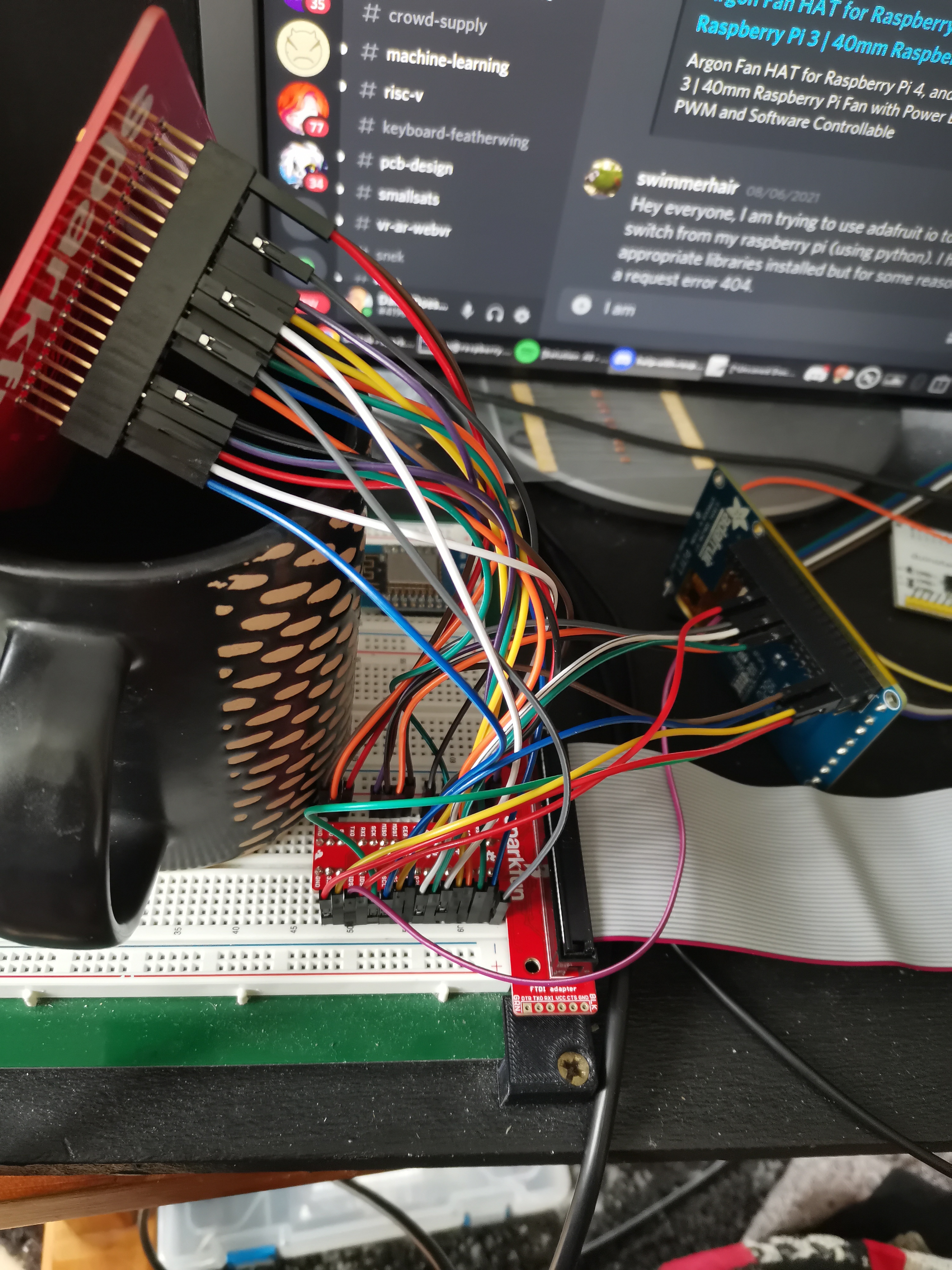
I can run the python script that comes with the hat, and it blinks the status led.
however avrdude cannot see a .conf file that is exactly where it says it is.
actually it has issue with linuxspi device. and this is what is listed in dev
/dev/spidev0.1 /dev/spidev1.0 /dev/spidev1.1 /dev/spidev1.2
I have the screen on SPI0, but im not sure how to use SPI1 to interface with the programmer
 cobalt raven
I am trying to run some services on an old RPi2. What parameters should I monitor to conclude that the RPI system is under load and that I should shut down a few services to ease some load.
opaque wagon
CPU and memory usage definitely
Maybe disk usage as well
Also CPU temperature can be important
 spark kayak
I don't know it it's the proper channel. The question is: How can i use ili9341 screen with x2046 touch controller? I found that fbtft is quite good, but its modules are not working on latest Kernel. Do you recommend any driver? I want it to work with octoscreen software, so the touch ability is useful. Model of my hw is rpi 3B
cobalt raven
thanks @opaque wagon
import board
import digitalio

yellowled_pin = 18
redled_pin = 17
greenled_pin = 27
blueled_pin = 26

# Activity LED
yellowled = digitalio.DigitalInOut(board.D18)

# Status LED
redled = digitalio.DigitalInOut(board.D17)
greenled = digitalio.DigitalInOut(board.D27)
blueled = digitalio.DigitalInOut(board.D26)

# How do i print these pinouts?


def dirty_pinout_printer():
        print(f"ACTIVITY LED PIN: {yellowled_pin}")
        print(f"RED LED PIN: {redled_pin}")
        print(f"GREEN LED PIN: {greenled_pin}")
        print(f"BLUE LED PIN: {blueled_pin}")
This is my led_pinouts.py file
I want to print the pinout directly from the redled, greenled, blueled variables. Instead of hardcoding the values another variables *led_pin
Is there a way to print the pin values from *led variables?
Please @ me when you respond to the above.
opaque wagon
Well, you could use a dictionary instead: (untested)
led_pins = {
    "red": 17,
    "yellow": 18,
    "green": 27,
    "blue": 26
}


def pinout_printer():
    for key, value in led_pins.items():
        print(f"{key.upper()} LED PIN: {value}")
@cobalt raven
cobalt raven
@opaque wagon No i meant how can i print whatever pin the redled, greenled variable are set to.
For example and know that im writing pseudocode here....
print(redled.pin)
opaque wagon
oh the value???
cobalt raven
The end idea is that the user can set and read the pins the led are set to without opening the code.
Yes the value.
I haven't found anything yet. Still looking.
opaque wagon
well, i haven't used blinka in quite a while so idk if this will work:
led_pins = {
    "red": digitalio.DigitalInOut(board.D17),
    "yellow": digitalio.DigitalInOut(board.D18),
    "green": digitalio.DigitalInOut(board.D27),
    "blue": digitalio.DigitalInOut(board.D26)
}


def pinout_printer():
    for key, value in led_pins.items():
        print(f"{key.upper()} LED : {'ON' if value.value else 'OFF'}")
@opaque wagon what do you use for gpio/electronics stuff on RPi?
opaque wagon
RPi.GPIO i think unless i'm using adafruit libraries, then blinka
 slim linden
How would I go about using adafruit blinka with python 2? Jython does not support python 3.

 steady rose
@slim linden blinka only supports python 3
 sand pumice
Hello! What's a common/recommended set of frontend, backend, storage options for Raspberry Pi based projects?
Goals:
- Must use React, whether needed or not, want to use/abuse this opportunity to learn React.
- Phone/Home automated NeoPixel lights, Pi Cam, Mic and Speakers powered by Raspberry Pi.
- Not using MQTT node red or similar publish/subscribe options. Reason is to keep the Raspberry pi project relatively self contained, low dependencies.
Current Design:
My Phone / Home Automation --> Pi hosting React on Node.js FrontEnd --> Flask Python 'backend' that uses bunch of AdaFruit NeoPixel/HW libraries. For storage, files and/or SqlLite, maybe with JSON extension to store/query relational table and/or JSON blob data.
Cheers!
uncut lagoon
im trying to use https://github.com/atanunq/viu to display an image on the console of my mini pitft 1.3" 240x240, but it can't display the half-block character: ▄
i tried changing font, using the uni1, uni2, uni3 and latin15 fonts, but it still can't render this, showing a "missing character" character on the display. is there anything i can do?

this is the best i could do to show the display

 deft ocean
 edgy veldt
Hi
edgy veldt
Hi
I'm trying to test one at the moment (among many other things). I've got a successful connection to it with UART and I've lots more work to do with it.
https://shop.pimoroni.com/products/gps-module-with-internal-external-antenna-neo-m8n

A stackable NEO-M8N based GPS module for use with M5Stack Core development boards, with a built in ceramic antenna and a 1m external antenna.
edgy veldt
nice
have u tried using U-CENTER?
Do you know how to map the (or how they map) the hardware pins to the pin numbers present on the UBX-MON-HW message?
deft ocean
So far I've only connected to it with a RP2040 Pico. I've avoided U-Center so far because I'm trying to do everything with NMEA type commands but I'm beginning to think that I will have to resort to UBX commands. I've not tried the UBX-MON-HW yet.
I'm slowly working through this datasheet:https://www.u-blox.com/sites/default/files/products/documents/u-blox8-M8_ReceiverDescrProtSpec_UBX-13003221.pdf
edgy veldt
UBX parsing is pretty ez
anf if you wanna change some configurations... so basic as baud rate you will need to use it
btw if u are using C... the nmea library https://sourceforge.net/projects/nmeap/files/ is working pretty well for me
Extensible NMEA-0183 (GPS) data parser in standard C. A directly linkable library intended for applications that want to embed GPS support.
 drowsy steppe
Hello! I'm building a (small) Raspberry Pi cluster. I have one Raspberry Pi 3b, and a Pi 4. I'm planning on getting more Pi 4's to make it bigger. Currently I'm powering the Pi 4 with a USB-C 45 W (so 9 amps) charger, so it won't overvolt, as it has a fan and I'm going to overclock it soon. The Pi 3 just has a normal (2.4 A) USB charger. This works, but as I get more Pi's having a laptop charger brick/wall wart for each one takes up a lot of space and is messy, so I'm hoping to have one power supply for them all. I'm considering:
(a) A POE+ network switch and some POE+ hats for the Pi's
(b) A big (like 5 ports) 60+ watt USB charging station, and plug the Pi's into that
How do you recommend I power a small Pi cluster? Thanks!
uncut lagoon
https://www.youtube.com/c/JeffGeerling/videos <-- you might want to check this youtube channel for some ideas
he also provides some information about the 2 versions of the poe hat, and shows what he uses for his cluster
he also shows how to do it and everything you may need, with examples of how to control kubernetes and all
faint sparrow
I have a Includes "40-Pin T-Shaped (Assembled) Breakout Board and Ribbon Cable
Includes GPIO Quick Reference Card" that cames with my raspberry 2.0, any idea what it is for exactly ?
???
 raw solar
The T-shaped breakout board is so you can connect your Pi to a breadboard to mess with stuff, the reference card is for the GPIO pinout so you know what pins are what and don't blow anything up
faint sparrow
2nd newbie question, I still can only interact with digital gpio right ?
turbid rivet
Interact? Depends on how much of what you're doing you know?
faint sparrow
so this would be fine to interact with an IC2 humidity/temp chip but not read voltage and guess the temperature myself
turbid rivet
If you're using an I2C chip, you're acquiring data via serial data, not by an analog voltage
I don't even think the Pi is capable of reading analog voltages via GPIO....
raw solar
I don't think it is
steady rose
@faint sparrow that ribbon cable thing is basically same as this:
https://www.adafruit.com/product/2028
which has a photo with breadboard to give better idea of how you'd use it
it'd let you interact with all of the pi's pins on a breaboard, in whatever way you want. good pi pin reference here:
https://pinout.xyz/#
yes, you can do I2C. also SPI.
pi's don't have ADCs, so can't read voltage
but lots of I2C and/or SPI ADC breakout options
restive venture
i am getting connection failed error when try to connect with thingspeak cloud
Importing modules
import spidev # To communicate with SPI devices
from numpy import interp # To scale values
from time import sleep # To add delay
import thingspeak
channel_id = 1999361 # PUT CHANNEL ID HERE
write_key = 'XRL09Q0VZJFL' # PUT YOUR WRITE KEY HERE
read_key = 'DJUV8KF8ATB6' # PUT YOUR READ KEY HERE
Start SPI connection
spi = spidev.SpiDev() # Created an object
spi.open(0,0)
Read MCP3008 data
def analogInput(port):
spi.max_speed_hz = 1350000
adc = spi.xfer2([1,(8+port)<<4,0])
data = ((adc[1]&3) << 8) + adc[2]
return data
import time
from w1thermsensor import W1ThermSensor
sensor = W1ThermSensor()
def measure(channel):
try:
soil_moisture = analogInput(0) # Reading from CH0
soil_moisture = interp(output, [0, 1023], [100, 0])
soil_moisture = int(output)
temperature_of_water = sensor.get_temperature()
# write
response = channel.update({'field1': temperature_of_water, 'field2': soil_moisture})
    # read
     read = channel.get({})
     print("Read:", read)

except:
     print("connection failed")
if name == "main":
channel = thingspeak.Channel(id=channel_id, api_key=write_key)
while True:
measure(channel)
# free account has an api limit of 15sec
time.sleep(15)
faint sparrow
Have a RasPi 4 used in a rover along with multiple other sensors. When I attach the BNO085 sensor using the UART-RVC wiring found in the docs (https://learn.adafruit.com/assets/94966), the WiFi drops out shortly after powering on the system. I suspect it is pulling too much power since that wiring requires two 3v connections. On a tester RasPi 4, the following code works reliably. Already confirmed that WiFi is stable on the rover RasPi when the BNO085 is not attached. Any ideas on what else I can try? I'm using UART-RVC due to other constraints on how my rover is set up. It should work, aside from this new issue with WiFi power.
import serial uart = serial.Serial("/dev/serial0", 115200) from adafruit_bno08x_rvc import BNO08x_RVC rvc = BNO08x_RVC(uart) while True: try: yaw, pitch, roll, x_accel, y_accel, z_accel = rvc.heading print("Yaw: %2.2f Pitch: %2.2f Roll: %2.2f Degrees" % (yaw, pitch, roll)) print("Acceleration X: %2.2f Y: %2.2f Z: %2.2f m/s^2" % (x_accel, y_accel, z_accel)) except Exception as e: print(e) pass
faint sparrow
My pi 2.0 has been plugged on the TV for 3 years doing nothing. All those ethereum/bitcoins lost 😦
Was looking everywhere for ti last week and found it connected to the TV because there was a suspect mouse near the TV
faint sparrow
faint sparrow
Have a RasPi 4 used in a rover along with multiple other sensors. When I attach...
It seems like something else in my system is using the same serial0. I moved the P0 to be powered from the BNO085 3vo pin instead of the RasPi4 3v pin and that seemed to make it a little more stable. But after running this code and seeing the sensor data, it started to report an exception, and then I lost my SSH connection to the RasPi4 (via WiFi). So, I'll look for what else could be using serial0.
steady rose
by default, pi creates a login shell on serial0
can disable in raspi-config or by editing /boot/cmdline.txt
faint sparrow
faint sparrow
It seems like something else in my system is using the same serial0. I moved th...
So, for anyone here, the issue was fixed by properly disabling the Serial Console! I'm now watching a never ending stream of sensor data coming from the BNO085. 🥳
Info from the pinout docs here (https://pinout.xyz/pinout/pin10_gpio15)
UART can be used to talk to Serial GPS modules or sensors such as the PM5003, but you must make sure you disable the Serial Console in raspi-config first.
As well as the documented steps for doing there here (https://www.raspberrypi.org/documentation/computers/configuration.html#disabling-the-linux-serial-console).
The comprehensive add-on boards & GPIO Pinout guide for the Raspberry Pi
The official documentation for Raspberry Pi computers and microcontrollers
faint sparrow
steady rose
by default, pi creates a login shell on serial0
Read your message after finding the solution. Thanks! You were absolutely right!! 🙂
 lucid crest
I was wondering if I could get some help with a Raspberry Pi 4B running Ubuntu. Specifically, I'm using the serial port and I2C bus that are part of the RasPi (As opposed to an external USB converter like FTDI). I found that the /dev/i2c-1 and /dev/ttyS0 are set to inaccessible permissions at boot. Is there an easy way to set these to usable permissions with each bootup? Or am I stuck running chmod each time?
I received a suggestion of using udev rules, but I can't get my head around how to setup the matching (because these are not USB devices with lots of ATTRS), nor can I figure out the syntax for running the change mode portion. (I thought I saw somewhere that it's just MODE=0666 or something like that, but I want to confirm.)
faint sparrow
@lucid crest permissions and memberships in a group
 $ groups
nomaku dialout cdrom floppy audio dip video plugdev netdev bluetooth
user (login) named nomaku has membership in group dialout and so may use the serial port.
 $ ls -la /dev/ttyS0
crw-rw---- 1 root dialout 4, 64 Aug 13 14:19 /dev/ttyS0
So, for some reason, the permissions I see when I do that is this:
crw------- 1 root root 89, 1 Jul 21 19:00 /dev/i2c-1
ubuntu@ubuntu:~$ ls -l /dev/ttyS0
crw--w---- 1 root tty 4, 64 Aug 13 21:37 /dev/ttyS0
the user is already a member of the tty group, but because it's not both RW, it's still not working 😦
faint sparrow
I've only used the TTL serial in 9front.org which is way different.
The old MS-DOS COM1 thru COM4 mapped to /dev/ttyS0 through /dev/ttyS3 iirc.
Those were real USART chip based ports.
There used to be a Linux specific website that talked a little about i2c on a Linux system's motherboard.
lucid crest
Ok, thanks for the info.
faint sparrow
I don't quite remember this one:
https://elinux.org/Interfacing_with_I2C_Devices
 bitter loom
Hello,
I am trying to get two of these displays (https://www.waveshare.com/wiki/3.5inch_DPI_LCD) running from my GPIO on a pi
Can I just use a Y splitter to have both displays showing the same output? Touch doesn't matter and I won't use it, so does that mean I don't need an i2c multiplexer?
faint sparrow
That's not typically done that way.
faint sparrow
I don't know that you can do that as a beginner asking questions. Sounds advanced.
I would put it on some kind of i2c repeater and fan out from there, accepting double overhead on the microcontroller (or in this case, the RPi).
bitter loom
the wiki shows that the only i2c pins are for the touch
not needing the touch means that surely I have no use for i2c, and could just Y split the pins that matter... right?
bitter loom
sure, I don't intend to buy one, I can just solder my own GPIO Y splitter
faint sparrow
I would find instructions you trust.
Then if it doesn't work out, you'll know why.
bitter loom
there's no instructions for this, it would seem
I've really tried to find something but nothing has come up
faint sparrow
Well you can very likely use 7400 series IC's to get something closer.
bitter loom
(probably because a duplicated display off GPIO isn't very useful for most people)
faint sparrow
Find a buffer in the 7400 series IC's that explicitly states you can connect inputs together, directly or maybe through diode OR circuits (I don't know the details; it's not an approach I'd probably resort to).
Also the SeeSaw module from Adafruit is worth a quick glance.
bitter loom
i see
faint sparrow
SPI can probably listen passively.
So it might be a candidate for a fan-out circuit.
As long as you're not using MISO but only MOSI.
I would have to guess you'd want a proper buffer circuit for each.
If you had enough GPIO pins you could bitbang the output(s) in parallel, too.
If you do try to do a hardwired Y I'd think schottky diodes inline might be helpful.
(and maybe 5k to 10k ohm resistor too).
#help-with-hw-design seems to attract people with detailed harware development experience.
This post claims you can setup a kind of ring buffer by chaining SPI serially:
https://electronics.stackexchange.com/questions/521980/spi-and-multiple-devices
 sick quartz
I’d like to use a pi zero w’s gpio emulate a SPACE BAR/ENTER keyboard press, within a browser running on the pi zero. (Ex: Start/Stop a YouTube video playing in the browser running on the pi zero) does Blinka have that capability? gpiozero?
I’m trying to avoid an additional keyboard/microcontroller.
raw solar
Are there any 5-7" displays for the Pi that are higher resolution than 800x480> Ideally like 1080p or better?
turbid rivet
bitter loom
Hello,
I am trying to get two of these displays (https://www.waveshare.com/wiki/...
I believe with DPI it is possible to split the display output. It’s not ideal, but I’m theory it should work okay. @faint sparrow is probably thinking an I2C or SPI display with conflicting feedback, but a dpi touchless display should have little to no conflict nor signal deformation in parallel. Touch will be funky, so you’ll have to find a way to disconnect the touch on at least one of the two displays, and the only other concern I would have is current draw. Make sure your pins are capable of driving the two displays, the backlight can draw a good amount of current…
mint pagoda

Haiway 7 inch Small HDMI Monitor, 1024x600 Resolution Small 1080P Portable IPS Monitor with Remote Control with Built-in Dual Speakers HDMI VGA Input for Gaming CCTV Raspberry Pi PC (7 inch IPS)
raw solar
Is... Is it 600p or 1080p? It can't be both
turbid rivet
raw solar
Are there any 5-7" displays for the Pi that are higher resolution than 800x480> ...
800x480 is definitely the limit on 5" screens, the pixel density there is comparable to a 24” 4K screen iirc
It’s definitely not 1080p
raw solar
I just don't understand why I can have a 1440p 6" screen on my phone but I can't get a 1080p 7" display DX
bitter loom
turbid rivet
I believe with DPI it is possible to split the display output. It’s not ideal, b...
I'm probably just not going to connect the touch pins at all since I don't need touch functionality. Power was one thing I was thinking about but that's fairly easy to handle. If I can just run two of them from the same pins then it would save me sooooooo much time lol
turbid rivet
Worth a shot, at least. I don’t see this possibly breaking anything, at the very least.
turbid rivet
You might want to break out the power from a separate supply, just in case.
bitter loom
Yeah
Do you think it's possible to remove the digitizer entirely? or is that gonna be glued hard
turbid rivet
Digitizer? Not sure what you’re referring to…
umbral sable
The touch-sensitive layer of the panel, most likely.
bitter loom
turbid rivet
Digitizer? Not sure what you’re referring to…
The glass part that picks up the touch input
 muted jewel
Hey everyone, I'm having trouble with a project. When I test the parts separately they're all good. When I connect them they don't work. I think it might have something to do with the power? Not sure
Here's the parts list:
-
Adafruit Mono 2.5W Class D Audio Amplifier - PAM8302
-
Mini Metal Speaker w/ Wires - 8 ohm 0.5W
-
PowerBoost 1000 Charger - Rechargeable 5V Lipo USB Boost @ 1A - 1000C
-
Lithium Ion Polymer Battery - 3.7v 500mAh
-
Raspberry Pi 3 - Model B
-
Waveshare 3.5inch Resistive Touch Display (C) for Raspberry Pi, 480×320
-
Various buttons and wires
 hardy plaza
Yeah, the power. You're going to need to pay attention to the power requirements, basically sum up all the device's currents and make sure your power supply has that plus a bit of buffer. You're not likely to get anything working using only a 1 amp supply.
muted jewel
Oh OK. Thank you for the fast reply. So I need more amps to pump through the device to be more than all the components added together?
hardy plaza
If the accumulated current of all your devices is say, 2.5 amps, you're going to need at least a 3 amp supply. More is better, and higher quality power supply is better, especially since this is an audio amplifier. Maybe check out Pololu as they have a ton of options.
muted jewel
Awesome. Thanks for the help 🙂
hardy plaza
Sure, happy to help.
gentle briar
Note, you'll also need a LiPo that can supply the input current: a step-up supply like that will need to draw more current from the cell than it provides at its output (conservation of energy)
turbid rivet
bitter loom
The glass part that picks up the touch input
Yeah, that's gonna be glued hard. I wouldn't even attempt that on most screens...
bitter loom
rip :( why are all the screens being sold touchscreens, it's annoying af that there's so few non touch options
turbid rivet
It's harder for companies to stock non-touch, since they can usually accept touch in non-touch applications, but not the other way around.
I can't think of an application where touch gets in the way of things enough to cause issues where non-touch wouldn't...
bitter loom
i'd expect non touch stuff to be cheaper and there's the added weight of touchscreens
but anyway, that's just me ranting
turbid rivet
Touchscreens, at least modern cap-touch, weigh so little that the weight difference should be negligible on most of them. Non-touch is cheaper, but they're rarely stocked. If you order directly from a manufacturer, they wait for an order confirmation to glue the screen to glass so they can confirm the need for touch before finalizing the display. Suppliers, unfortunately, don't have that luxury, so they just stock whatever is forecasted to sell more reliably. With touchscreens becoming more and more common, it just happened that way. The price difference is probably negligible in a one-off, anyways, so as long as you have the non-touch options available at scale, most people are happy.
raw solar
Touch can end up being cheaper because they can just make more touch than non-touch, and the non-touch gets more expensive due to lower volume of sales. Plus like Hem said, you can generally use a touch in a non-touch application [just don't connect/enable the touch part]
turbid rivet
I know applications where they just tape back or even cut off the touch pigtails in prototyping....
Made me so sad when they cut it for a one-off.
faint sparrow
anyone know of a good pi zero case that can hold the camera and has space for the soldered pins
the stock case is too small the pins dont allow you to close it
ripe berry
Maybe this one? https://blog.adafruit.com/2021/02/18/a-raspberry-pi-zero-w-and-hq-camera-case-3dthursday-3dprinting/

Adafruit Industries - Makers, hackers, artists, designers and engineers!
Dan shares: The case is pretty simple to print, and uses 8 8mm long M2.5 button head cap screws to hold everything together. download the files on: Every Thursday is #3dthursday here at Adafruit! T…
bitter loom
@turbid rivet my stupid solution actually worked lol

the cables are a MESS and a huge pain to plug in but it works!
turbid rivet
I figured it would, but didn’t know anyone that would actually wire it out LOL
That’s great!
turbid rivet
bitter loom
the cables are a MESS and a huge pain to plug in but it works!
For a finished build, you could consider some ribbon cables with one of something like this: https://www.amazon.com/MakerFocus-Raspberry-Model-Expansion-Extension/dp/B06WWRZ7PS

MakerFocus Raspberry Pi GPIO Extension Board, Raspberry Pi 4 Expansion Board GPIO 1 to 3 for Pi 4B/Pi3/2
If you don’t have any i2c devices on the same bus, you could probably get away with disabling the touch in software, otherwise you can clip the pins or (carefully) make a disconnect in one of the ribbon cables.
bitter loom
👀
this looks good
would be infinitely more convenient too rather than painstakingly plugging each one in!
ty, I will buy one and some ribbon cables
turbid rivet
The interesting part in all of this is if you just remove the requirement of the exact touch position, you can make it to detect touch events on any screen via the interrupt pin
And if you want to distinguish which screen, you simply move the interrupt pin on one screen to a different pin on the 2x20 header
bitter loom
that's good to know at least
I'm unlikely to use touch in any way, since the displays will be awkward to touch
turbid rivet
Your screens can become a giant toggle switch if you program it to be one haha
 young fjord
I'm looking for advice about an easy kit/setup to make a raspberry pi web cam.
turbid rivet
young fjord
I'm looking for advice about an easy kit/setup to make a raspberry pi web cam.
Something like this? https://www.the-diy-life.com/how-to-make-a-raspberry-pi-zero-wifi-security-camera/

Step by step instructions to assemble and configure a Raspberry Pi Zero W as a WiFi security camera, also accessible over the internet.
young fjord
Thanks that looks perfect
 feral folio
webcam as in IP camera, or webcam as in USB camera?
for USB camera, I found https://github.com/showmewebcam/showmewebcam to be much faster and easier than https://github.com/geerlingguy/pi-webcam

GitHub
Raspberry Pi + High Quality Camera = High-quality USB Webcam! - GitHub - showmewebcam/showmewebcam: Raspberry Pi + High Quality Camera = High-quality USB Webcam!

GitHub
Automation to configure a Raspberry Pi as a USB OTG webcam - GitHub - geerlingguy/pi-webcam: Automation to configure a Raspberry Pi as a USB OTG webcam
young fjord
I was thinking about as an IP camera
 proud kayak
MotionEye or MotionEyeOS would be a good pick then
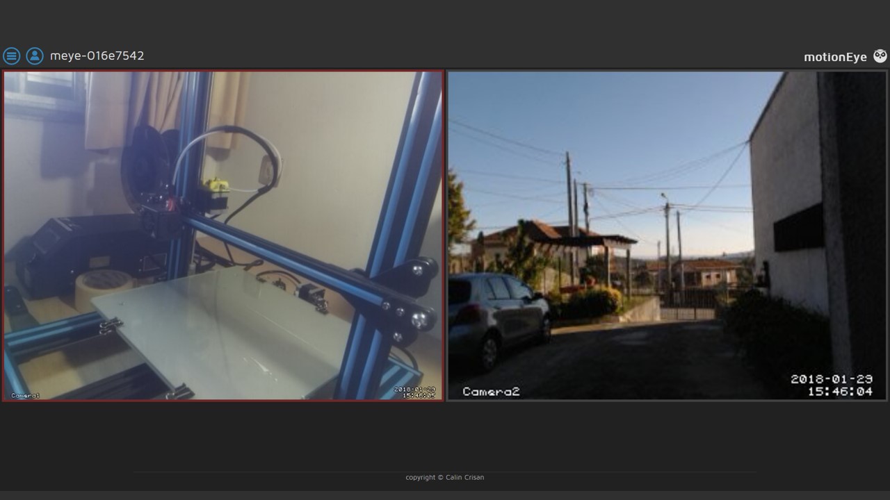
Do you want to turn your Raspberry Pi into a surveillance camera system? The best way to do it is using MotionEyeOS. In this post we'll show you how to get started with MotionEyeOS on your Raspberry Pi.
I have a setup with MotionEyeOS running myself with a couple of external IP cameras but you can also use one connected with a ribbon cable or through USB
Ah just realized that @turbid rivet already linked to a guide using MotionEye
+1 to MotionEye then 😅
raw solar
Has anyone used OctoPrint with something like a Mini PiTFT? I was thinking about putting the ones with buttons on my servers so I can see a quick status without having a full monitor, and have quick action buttons to cancel/pause prints or shut down/restart the system
hard pike
raw solar
Has anyone used OctoPrint with something like a Mini PiTFT? I was thinking about...
I think that’s kind of an idea that the Octoprint people had. There was at one point a lot you could buy with a touch screen that ran Octoprint on a pi. I have no clue if that still exists.
raw solar
I think that still exists, but I want to use something like this https://www.adafruit.com/product/4393 and just have like, the most basic of options and stats, not a full control interface
If you're looking for the most compact li'l color display for a Raspberry Pi (most likely a Pi Zero) project, this might be just the thing you need!The Adafruit Mini PiTFT - ...
hardy plaza
That's one of my favourite little displays, have been putting them on my robots and running htop, or using a radio keyboard and typing on the console. It's like a 4 pt font but still quite bright and readable. There was a period where you had to pin your kernel to a version from last December but that bug has been fixed in the newer kernels so now after it does its (rather extensive) kernel modifications it just runs.
raw solar
htop presents well on there?!
hardy plaza
vera small
raw solar
I didn't think you'd be able to have it be useful
hardy plaza
actually, I run htop on the 320x240, regular top on the tiny one
turbid rivet
I was going to use https://plugins.octoprint.org/plugins/touchui/ but even that's a bit big for that tiny tft
OctoPrint Plugin Repository
This plugin will transform the OctoPrint layout into a Mobile/TFT friendly layout. With larger buttons and a responsive layout down to the smallest resolution possible. It will mimic pointer events as touch, so you can hook up those touchscreens. It also supports a virtual keyboard.
raw solar
I kinda just want like, IP/WiFi status, reboot/shutdown
turbid rivet
OctoPrint Plugin Repository
This plugin implements the software control side of an OctoPrint Control Panel for Octopi. The hardware half is a series of 4 buttons, an OLED screen and a 3D printed case that mounts on the printer next to the Raspnerry Pi so it can be plugged in to the header pins.
 raw solar
Yeah, not sure how useful 240x135 will be, lol
hardy plaza
I can fire it up and take a photo if you like.
raw solar
Sure, that'll be faster than me setting it up on mine XD
hardy plaza
Different robot, just a minute...
raw solar


 hardy plaza
yeah yeah yeah
raw solar
lol
hardy plaza
Professional camera on tripod, 2 sec timer, unmount SD card and put back in camera, take photo, turn off camera and put SD card back into workstation, open file in Gimp, resize and save.
 raw solar
No graphs :O
hardy plaza
I've never configured top for that on that robot. But you can get an idea of the size. Actually, you could configure htop to remove features you don't want and have graphs.
I do like seeing the CPU usage graphs, yes.
raw solar
I basically just want the graphs XD
hardy plaza
Then I'd just go with htop and set your configuration accordingly. I think the process list is entirely disable-able.
I've got an 8 core NanoPi Fire3, which is just slightly bigger than a Pi Zero, and it's cool to see the cores fire up when compiling Python on it.
raw solar
Actually, can you splitscreen htop and something else on there? Might use the one that's double the size/resolution
hardy plaza
I've used the 240x135, the 200x200, the 320x240, and the full-Pi size one (can't remember the resolution of it). Obviously the bigger ones are more useful, but the 200x200 would be good if you're going to vertically split screen.
raw solar
Oh, there's a 200x200? I only saw 240x240
hardy plaza
Ah sorry, you're correct.
If you're looking for the most compact li'l color display for a Raspberry Pi (most likely a Pi Zero) project, this might be just the thing you need!The Adafruit Mini PiTFT - ...
hardy plaza
I'm wrong gender for multiprocessing functionality and am in the middle of coding, reading The Guardian, drinking my tea, and dealing with my cat ecking behind me. Buffer overflow...
raw solar
Lol, that's bound to happen
 vale raptor
What is the partnumber of the raspberry pi 3b RJ45 Jack? It snipped off and I want to replace it
uncut lagoon
vale raptor
What is the partnumber of the raspberry pi 3b RJ45 Jack? It snipped off and I wa...
https://www.raspberrypi-spy.co.uk/2014/07/raspberry-pi-model-b-3-5mm-audiovideo-jack/
according to this, you need a 3.5mm jack with 4 poles
i would assume that anything that fits is fine?
i dont know about hardware
umbral sable
RJ45 is the Ethernet jack, not audio.
uncut lagoon
🤦♂️
ive never seen "jack" being used for an internet port
and skipped the rj45
idiocy of mine
FOUND IT
A70-112-331-N126
vale raptor
Is it the same as on a regular 3B? I mean not 3B+
uncut lagoon
can't find anything about the 3b
the 3b and 3b+ seem to be the same
possibly faster cpu or more ram
vale raptor
Well okie thanks 🙂
raw solar
I think they're the same parts and layout aside from CPU and RAM, yeah
feral folio
anybody know a good place to ask about device tree overlay stuff and/or DSI displays on the raspberry pi? I've built a PCB that has a sn65dsi83 DSI to LVDS bridge chip on it, and I've written a device tree overlay which appears to load cleanly, but it never actually talks to the sn65 over i2c.
raw solar
This is probably the best place, or #help-with-hw-design
 full estuary
is there a trick to getting a macropad to show up as a device in linux? been plugging and unplugging or hitting the reset button while holding down the encoder button, with no luck -- nothing in /dev and nothing in my file browser
it shows up in dmesg with Product: RP2 Boot
so i'm guessing that's good
hardy plaza
Try tail -f /var/log/messages and see what happens when you plug it in.
Or maybe also tail -f /var/log/syslog (there are multiple logs on a Pi)
full estuary
should i be asking elsewhere if i'm plugging the macropad into my pc? i figured because the brain is a rp2040 this would be the place to ask -- i can take this to #help-with-arduino instead if this isn't the place
hardy plaza
I think you're probably fine here. It's not an Arduino. You could also try the Pico Discord server, but people here may be able to help, it's a big community.
full estuary
alrighty
i've checked the output of dmesg and journalctl -r ( i'm on manjaro, so no /var/log/messages or /var/log/syslog ), and when I plug it in while holding down the encoder I get this: usb 1-4: USB disconnect, device number 9 usb 1-4: new full-speed USB device number 10 using xhci_hcd usb 1-4: New USB device found, idVendor=2e8a, idProduct=0003, bcdDevice= 1.00 usb 1-4: New USB device strings: Mfr=1, Product=2, SerialNumber=3 usb 1-4: Product: RP2 Boot usb 1-4: Manufacturer: Raspberry Pi usb 1-4: SerialNumber: E0C912952D54
but nothing new shows up in /dev and no new storage devices show up my file browser
gentle briar
It could be a driver isn't attaching, or you need a udev rule to create the device node.
full estuary
that's probably right, cause it works fine on my windows machine
full estuary
i used a modified udev rule from the earlephilhower/arduino-pico repo, still no luck ( i changed the group so it matches the group used for this stuff on Arch: SUBSYSTEMS=="usb", ATTRS{idVendor}=="2e8a", ATTRS{idProduct}=="0004", GROUP="plugdev", MODE="0666" )
still no luck
but it works on Windows 10 -- i was able to upload a super simple sketch ( just sets up serial and prints out "testing" every second ) by compiling the u2f and dragging it to the RPI-RP2 storage device
gentle briar
your journal shows a product ID of 0003 and your udev line shows a product ID of 0004. While that may well not be the issue, I did notice the mismatch.
full estuary
i guess all it took was a reset, using udevadm to reload the rules just didn't do it. weird!
figured that out because i copied the udev rules from my laptop (where it works) to the desktop, and after a udevadm --reload-rules it still wasn't working
feral folio
k, I'm back with my actual question about DSI/device tree: https://www.raspberrypi.org/forums/viewtopic.php?f=44&t=318186 -- basically, I've got a custom PCB with a DSI-LVDS bridge chip on it, and I've made a device tree overlay file. When I load my overlay with dtoverlay, I don't see any actual I2C traffic, even though I can tell (from udevadm monitor, dmesg -w, and ftrace) that the driver is being loaded. What am I missing?
feral folio
🤦♂️ it seems to work if I add the overlay to /boot/config.txt instead of loading at runtime with the dtoverlay command.
feral folio
oh wow, on the 15-pin DSI connector, it's lane 0, clock, lane 1. On the 22-pin connector used by the CM4IO, it's lane 0, lane 1, clock.
 lethal flame
Hello, I got a problem with my Matrix LED Panel and my Raspierry Pi.
I've got a Raspberry Pi 1 B+, a Matrix LED Panel from Adafruit 32x64 px, the Adafruit Hat for the Raspberry
Pi and a power supply with 1500mAh and 5V.
I installed the library from GitHub (https://raw.githubusercontent.com/adafruit/Raspberry-Pi-Installer-Scripts/master/rgb-matrix.sh).
But every time I wanna start one of the demos:
(sudo ./demo --led-rows=32 --led-cols=64 -D1 runtext.ppm) only 2 LED light up.
My question is, is the command wrong or do I have to do a few more configurations?
ripe berry
Well, for starters, I don't see that the Pi 1 is specifically listed on the compatibility for the Hat... it's for "Raspberry Pi Model Zero/A+/B+/Pi 2/3/ or Pi 4 with the Adafruit RGB Matrix HAT" Or are A+ and B+ models of "1"?
Also, are you sure your demo file is in the same directory, as your command line directs?
Lastly, I don't see the runtext.ppm part of your command in the directions for the Hat, and I don't think I've used something like that with my Hat. Here's what the directions say ```
Here’s how to run one of the examples — a rotating colored square. Because this code is performing low-level hardware operations, it must be run using the sudo command:
sudo ./demo -D0 --led-rows=32 --led-cols=16
That’s for a single 32x16 pixel RGB matrix. If you have a different size, change the --led-rows and/or --led-cols values. Add a --led-chain value if multiple matrices are chained.
There are 12 different examples in the demo program (0 through 11), chosen with -D. For a full list of the program’s options, just type demo.
 narrow wave
A+ and B+ on their own mean 1A+ and 1B+
ripe berry
narrow wave
A+ and B+ on their own mean 1A+ and 1B+
Cool. I got started later than that 😄
narrow wave
I only really got into Raspberry Pi's with my 4B, so I get that! I just remember feeling awed at my friend's model B when he got it, how such a small thing was a computer, probably early 2013? I'm just glad I get to own one myself now
lethal flame
so is it possible with the rbp 1 b+?
lethal flame
ripe berry
Lastly, I don't see the `runtext.ppm` part of your command in the directions for...
I only saw it that way, that's why I tried it
ripe berry
Maybe try it without and see. What directions are you following? I used the tutorial here and everything worked perfectly on my Pi 2. https://learn.adafruit.com/adafruit-rgb-matrix-plus-real-time-clock-hat-for-raspberry-pi/overview
Adafruit Learning System
DIY your very own Times Square sign
lethal flame
i tried the command "sudo ./demo -D0 --led-rows=32 --led-cols=64" but that wont help 😦
ripe berry
I would just suggest, then, if your demo file is in the same directory as your command directs and it's still not working, go carefully step-by-step through the tutorial.
lethal flame
but the power supply should be enough right?
ripe berry
Check the requirements. I use a 16 x 32 and I have a 2A power supply. The large 32 x 64 matrix at Adafruit says the power requirements are 5V regulated power input @ ~4A (with all LEDs on). If you have a smaller model, tho', power requirements will be less.
(smaller meaning smaller size overall, not matrix size)
lethal flame
okay
so my power supplay with 1,5 A is not enough XD
*supply
maybe thats the problem why only 2 LED lights up?
faint sparrow
I'm surprised very minimum isn't probably 32x64*15mA ie: 30A
hard pike
faint sparrow
I'm surprised very minimum isn't probably 32x64*15mA ie: 30A
That would be an expensive supply
faint sparrow
I mean i've never seen leds under 15mA so i'm surprised there are ones that light enough at like 1-2mA
especially RGBs ones
ripe berry
These are probably not continuously lit. Possibly flashing at 60 Hz or something?
faint sparrow
It's hard to tell with the lack of transparency on what leds these are exactly
hard pike
Max draw of sk6812 is 40mA
That’s with all three colors on at full brightness
10% brightness is just 4-5mA
And sk6812 are plenty bright at 10%
Single color will probably be around 1.3mA at 10%
If you average 3mA per LED, that’s 1/5 of 30A or around 6A for all
Even then, it’s not likely that you’ll even get close to 6A so 4A is probably more than enough
faint sparrow
I have a 96x8 RGB display.
Maxes out close to 999 mA.
800 mA seems typical.
That'd work out to 1.3 mA per one (of 768) LED's during a self-test with all pixels lit.
Maybe 0.433 mA per color element.
(I don't know if it's RGB or RGBW).
768 locations lit in 'pure' white for this test.
Definitely under 1 Ampere.
(at 5 VDC)
hard pike
Are those neopixel compatible?
faint sparrow
No, it has an STM32 secondary board that handles the comms; I don't know what handles the display itself.
I am fairly sure the pixels they make can be had individually and would very likely need to be SMT.
I don't now how they constructed the one I have. ;)
umbral sable
It's likely multiplexed, so the peak current per LED is higher than the average.
 burnt scarab
Hi there I have a question in regards to a PI zero
I had my pi zero plugged in and running and I unplugged the mouse and key board by removing the micro usb cable as well as pulling the hdmi mini for the display. I left the power cable plugged in. My thought was the pi zero would stay on and when I was done with the mouse and keypad I could bring it back and continue where I left off. When I plugged the mouse/keyboard back in as well as the display cable I could not view anything on the screen. Eventually I just had to unplug the power to recycle power back. At that point the pi was back up. Is there a way to complete what I was attempting. Is there a way to wake up the pi after I plugged the external devices back in?
ripe berry
Have you tried disabling sleep?
burnt scarab
I did not...
So do you think that the pi went to sleep and then when I plugged the mouse/keyboard back in it couldn't recognize the hardware and wake it up?
steady rose
it could be something else related to hot plugging the HDMI. what's the goal?
burnt scarab
come to think about it....I do not belive the PI zero goes to sleep
burnt scarab
steady rose
it could be something else related to hot plugging the HDMI. what's the goal?
I wanted to be able to share one set of mouse/keyboard while running multiple pies. Jumping back and forth as needed
steady rose
share display also?
burnt scarab
No, just the cable.
 uneven solstice
With two different Pi Zeroes, one of them W, I noticed that it's possible to cause a system freeze when plugging/unplugging USB devices, requiring to power cycle them. I imagine it's something power related (not lack of power, but the change), as it's more likely to happen when I connect or disconnect a 4 ports hub with an USB camera, Arduino Mega and WiFi module
It can happen regardless if I use an 1A power bank or a 5A power supply
burnt scarab
uneven solstice
With two different Pi Zeroes, one of them W, I noticed that it's possible to cau...
Thanks I suspect this is what is occuring.
raw solar
Is fan control under raspi-config in degrees C or F?
It doesn't specify, but I have a feeling it's in C?
hardy plaza
The value returned by the OS is in Celsius.
 ripe pike
👋 is there a way to follow / download the nightly raspberry pi OS builds? I'm hoping to test out the new bullseye packages sooner than the official release
steady rose
@ripe pike there's this utility:
https://github.com/Hexxeh/rpi-update
and also this:
https://downloads.raspberrypi.org/
(but that might just be releases?)
 final kiln
anybody know what's the best touchscreen display to use with Adafruit CYBERDECK HAT on Raspberry Pi 400
ripe pike
steady rose
<@!700515928252874763> there's this utility:
<https://github.com/Hexxeh/rpi-upda...
That looks very promising, thanks! Looks like they haven't ripped a bullseye version yet, but I'll keep an eye out
 south tusk
final kiln
anybody know what's the best touchscreen display to use with Adafruit CYBERDECK ...
south tusk
final kiln
anybody know what's the best touchscreen display to use with Adafruit CYBERDECK ...
I don't know anything about the CYBERDECK hat, but the TFT displays from DFROBOT are fantastic and they don't use any GPIO lanes. Power and data over a single FPC cable to the DSI ZIF connector on the RPi. Not only that but there are standoffs on the display itself that screw directly into the board. Makes for a nice, clean install.
The only quirk I'm trying to figure out is an RGB test pattern that comes up for a few seconds when the screen is powered up. Trying to interrogate the display and figure out how to disable this test pattern. Can't look professional with a big a** random rainbow gamut in the middle of the screen on power up.
uneven solstice
Is the splash screen from the display or from the Raspberry Pi? If it's from the Raspberry Pi, there should be a configuration to disable it https://www.raspberrypi.org/forums/viewtopic.php?t=17449
 quaint river
I'm trying to understand what the typical/standard procedure is for configuring an image prior to deployment. I want a workflow where once I burn the image to an SD card, I don't touch it after slapping it into a pi and booting up -- so for example, if my image is for a kiosk mode dashboard web page viewer, that image would already contain wifi configuration and a URL to load. My assumption going in was that this would mean hooking in to the OS build process, but I'm starting to get the picture that it's far more common to use a /boot partition on the image to add special files that the OS knows what to do with once it actually boots. My question is, can this be realistically automated? Say I'm using a Mac as my development machine, and I have a code repository with files that define the configuration for each deployment. Is it possible to script/automate modifications to a prebuilt image to include those extra boot files, producing a new image that is ready to be burned to an SD card?