#help-with-linux-sbcs
1 messages · Page 13 of 1
 tulip barn
i added it to a function to load faster
here's what i have, see if it helps
import time
camera = PiCamera()
camera.resolution = 4064, 3040
camera.framerate = 30
camera.start_preview()
print('starting camera')
time.sleep(2)
last = time.perf_counter()
def capture():
    for _ in range(0, 10):
        now = time.strftime('%d%b%Y-%H%M%S')
        filename = "/home/pi/" + now + ".jpg"
        camera.capture(filename)

capture()
curr = time.perf_counter()
print(repr(curr-last))
camera.stop_preview()```this was with JPG though and right now my camera is in a dark closet laying on the ground so it might have been faster since its all dark photos. I also dont have the HQ camera.
 lucid crest
If you're not using he HQ camera, shouldn't the camera.resolution line result in an error?
tulip barn
yeah, i changed it back to what you had
lucid crest
AH
tulip barn
and i only got 8 photos because they got overwritten, if i wanted all 10 i should have incorporated a counter to the file name.
or used some other naming that wasnt limited by seconds.
lucid crest
Gotchya
tulip barn
i'm also doing this on a raspberry pi 2 because of the ones i have a camera connected to was either the 2 or a 0W
lucid crest
Hmm, ok, with the same (4064,3040) resolution, moving it into a function speeds it up from 25 seconds to 14.
And yeah, dropping the resolution does increase the speed:
4064 x 3040: 14 seconds
2048 x 1520: 6 seconds
tulip barn
when i watched a youtube video on microphython i learned that loading stuff in functions will always load faster
lucid crest
Hmm, good to know. And yeah, that makes sense. The Python instance is reading from RAM instead of reading each line from Flash
tulip barn
the resoltuon might be the difference because of the time to write to the SD card. maybe create a ram drive to store the photos it might be even faster
bigger resolution = bigger file size.
lucid crest
Yeah, makes sense. Though, that's a bit outside my Linux knowledge so I gotta go do some googling
tulip barn
let me check i had one running a long time ago for a motion sensing video capture to store to ram drive
i think this is what i used, only changed the size from 1M to like 5G https://www.domoticz.com/wiki/Setting_up_a_RAM_drive_on_Raspberry_Pi
but it was on an 8g pi4. but i think you can adjust the size as you need. and then after the files are saved can add to your code system('mv /path/from/old(ram) /path/to/new
)
lucid crest
I used this tutorial to make the ramdisk: https://www.linuxbabe.com/command-line/create-ramdisk-linux

This tutorial will show you how to quickly create a RAM disk in any Linux distro. RAM disk is ultra-fast compared to even the fastest solid state drive.
I got a write speed improvement from 158MB/s to 256MB/s, but that only resulted in 10 frames taking 12.46 seconds rather than 14 😦
tulip barn
ah so not that much improvment
lucid crest
Yup. Though, I guess that also is reassuring that the write speed of my SD card is somewhat decent 🙂
tulip barn
yeah you probably have a decent card. I prefer the samsung pro endurance cards myself
lucid crest
These are the Sandisk Extreme Pro 64GB. I've been pretty happy with them. (Rated write speed is 90MB/s, and I just measured it at 158MB/s, so can't complain 😉 )
I'll check out the Samsung Endurance line. I'm guessing they have a higher MTBF for flash writes?
lucid crest
@tulip barn @steady rose Thank you for the assistance!
tulip barn
lucid crest
<@!452973999329116182> <@!337989520962093057> Thank you for the assistance!
sorry i couldnt be more helpful. hope you get the speed you are looking for
lucid crest
No worries, it got me to try a bunch of stuff that I hadn't thought of. (Plus it helps to know that I'm not the only one struggling with this.)
 fallow fox
After checking, my two sensors are exactly the same VL53L0X
 unreal stirrup
I am still struggling with my button triggering when it isn't pressed. It works fine when the rest of my system is not running. I tried adding a 10k external pull_up instead of the internal pull_up but this didn't help. GPIO.add_event_detect(sbutton, GPIO.FALLING, callback=button_interrupt, bouncetime=400) I am now wondering about a voltage drop or a ground reference problem. I really have no idea where to start digging for the answer. Does anyone have any suggestions where to look for the problem?
 steady rose
can't remember - were you getting reliable operation with a simple polling loop on the button? is the issue only when using the interrupt callback?
unreal stirrup
yes, I was having reliable operation with the simple polling loop
I have noticed more problems with the button when I have a switch to a secondary 5V supply turned off. The raspberry pi is running independently off of a power bank. I have no idea if this is related!
I also have a rotary encoder occasionally triggering when it shouldn't also. GPIO.add_event_detect(Enc_B, GPIO.RISING, callback=rotary_interrupt)
steady rose
it may be noise related. something causing the edge detect to false trigger.
 restive jungle
How can I use the official raspberry pi display as a normal hdmi display with https://www.adafruit.com/product/3551?gclid=Cj0KCQjwsqmEBhDiARIsANV8H3Zo0bCkF4PeKk0DB_oZb5KlYQWetyuHYCUvS_I0m2gGGPwalsUlpH8aArXEEALw_wcB or any thing else

If you love DIY cable-rigging, then these HDMI adapters are right up your alley! Making custom HDMI cables has never been easier. Just grab one of our HDMI ribbon cables, then swap and ...
 narrow wave
I believe that adapter is just putting the HDMI lines into a ribbon cable, and it isn't compatible with the display connector or anything made for the display connector (I might be wrong)
just looked into it, and yes, they're not compatible
restive jungle
Ok is there any other way to make it hdmi compatible
narrow wave
No, I believe it's proprietary, the layout of the connector
 raw solar
Pretty sure it's standard DSI... So this might work https://www.mouser.com/ProductDetail/STMicroelectronics/B-LCDAD-HDMI1?qs=aVyJF2WnouQctE9Rmn3wdA%3D%3D

Mouser Electronics
narrow wave
definitely read that it's not standard DSI
 novel bay
Hi, my RPi4 doesn't let me connect via SSH when connected to 5GHz.
For the same router, ssh works perfectly fine with 2.4GHz
tulip barn
novel bay
Hi, my RPi4 doesn't let me connect via SSH when connected to 5GHz.
For the same ...
can you ping it while on 5GHZ?
can you ssh out from it while on 5GHz?
and are you using DHCP or static and IP4 or IP6?
also your router might isolate the 5GHz like a guest network depending on its settings, you might have to look into that as well.
novel bay
I can ping it while on 5GHz
What do you mean ssh out?
If when I'm connected via SSH on 2.4 ghz I switch the network, via a vnc connection, the ssh connection gets terminated
tulip barn
novel bay
What do you mean ssh out?
you say you cannot connect while on 5GHz. so you mean client > SSH host doesn't work. but what if you are on the Pi and try to SSH back to your computer or another Pi?
novel bay
I haven't yet setup a static dhcp, but both 2.4 and 5.ghz bands are assigned a somewhat static ip since my network isn't crowded
novel bay
tulip barn
you say you cannot connect while on 5GHz. so you mean client > SSH host doesn't ...
Oh, I understand, I'll have to try that
tulip barn
novel bay
If when I'm connected via SSH on 2.4 ghz I switch the network, via a vnc connect...
i want to make sure i understand. You can log in to the Pi using VNC while on 2.4GHz. then while using VNC, you go in and change the network to 5GHz and then it drops you
novel bay
But do you think somehow there's a firewall on the interface when connected to the 5ghz band?
Since the error message I get is Connection refused
novel bay
tulip barn
i want to make sure i understand. You can log in to the Pi using VNC while on 2....
Yes
tulip barn
novel bay
Yes
thats because when you swap networks the 5GHz issues a new IP address.
novel bay
Yes and I have that ip with me when I try reconnecting
tulip barn
for example on 2.4 you might be 192.168.0.10 and on 5GHz you would be 192.168.0.11
novel bay
But both ssh and vnc won't work when connected to 5GHz
tulip barn
are you trying from within the LAN?
novel bay
As a matter of fact, when I started the headless config, I started with the 5ghz network and only after 3 re flashes i figured that I could give 2.4ghz a shot
novel bay
tulip barn
are you trying from within the LAN?
Yes
tulip barn
and is it static or dhcp assigned IP?
novel bay
Dhcp assigned, but the lease expires in a day so the same ip is assigned every time
Hey @tulip barn just give me a moment
I'll just verify a small thing and get back to you
tulip barn
no worries.
novel bay
So it's on the 5ghz channel right now
And it's letting me ssh
It's assigned the same ip that was assigned when it was on 2.4 ghz
I might have missed this or this was a really recent development
I'm sorry and thankful for your support.
I hope the debugging steps shared by you today might help someone in the future :D
tulip barn
novel bay
And it's letting me ssh
great!
unreal stirrup
If my button triggering unintentionally is due to noise is there anything I can do to mitigate it? I read that twisting the 2 wires together might help but my run is only 6" and the two wires are presently side by side. While digging into noise ideas I came across a post where they used ```
if not GPIO.input(20):
time.sleep(0.3)
recheck that button has been operated
if not GPIO.input(20):``` I don't fully understand what this code will do but I will explore this option unless someone can point me in a better direction.
restive jungle
raw solar
Pretty sure it's standard DSI... So this might work https://www.mouser.com/Produ...
Ya but where would I put the ribbon cable
raw solar
narrow wave
definitely read that it's *not* standard DSI
I have found conflicting information in researching this -- some places say it's standard DSI, some places say only the Pi foundation display works, some say it may or may not work with other displays... Can't find an official yes or no though. But I'm not sure if it's standard on the connector, or electrically, or both, if at all
raw solar
restive jungle
Ya but where would I put the ribbon cable
That board appears to have a connector on the back, but it's kinda hard to find info
restive jungle
Ya um do you think there’s a way to mirror the display of a jetson nano to a raspberry pi
raw solar
Uhhh... maybe with a USB capture device? Jetson Nano has HDMI out, right?
restive jungle
Uh ya
raw solar
You might be able to use an HDMI to USB capture device on the Pi and monitor the output there
restive jungle
I’m trying to do it wirelessly
raw solar
Ah... Not sure if there's a way to do that...
restive jungle
I might just have to re model the case and use a hdmi transmitter
 ionic stag
I couldn't find anything on this from Google, is there any documentation for using the hardware h.264 encoder from a file handle from, say, Go or C?
 elder violet
Is it possible to use the adafruit neo trellis rgb driver pcb 4x4 keypad with the raspberry pi pico or it's only compatible with the regular pi and the pi zero?
tulip barn
elder violet
Is it possible to use the adafruit neo trellis rgb driver pcb 4x4 keypad with th...
is this your product? https://www.adafruit.com/product/1616

This item is just for the Trellis driver PCB assembly: LEDs and buttons not included. Trellis is an open source backlight keypad driver system. It is easy to use, works with any 3mm LEDs and ...
narrow wave
they crossposted in general, it already got answered
tulip barn
thanx
 foggy nova
so i have 4 meters off neopixel stripes (120 Leds). can i use the rpi power supply or do i need an additional one?
 lost wolf
foggy nova
so i have 4 meters off neopixel stripes (120 Leds). can i use the rpi power supp...
lost wolf
foggy nova
so i have 4 meters off neopixel stripes (120 Leds). can i use the rpi power supp...
You'll probably want an external power supply with that many LEDs. Easy to tell if you power them up white (not full brightness) and they start turning yellow the further away from the Pi you get. But I would suggest using an external power supply to begin with. I'm not sure if they can damage the Pi.
foggy nova
lost wolf
You'll probably want an external power supply with that many LEDs. Easy to tell ...
ok so about 7-8 A Power Supply?
lost wolf
That should be plenty. I use a 5V10A but that's because it's what I have on hand.
You'll know if you need more if you get the dimming or color changing further down the line of LEDs.
foggy nova
Ok tysm
lost wolf
foggy nova
Ok tysm
Another trick I do is "inject" power in the middle of the strip instead of at the start. You can try that as well if it seems like one end isn't getting enough power.
 lilac obsidian
...Why have I never thought to do this... That's awesome.
foggy nova
lost wolf
Another trick I do is "inject" power in the middle of the strip instead of at th...
ty
is this powersupply acceptable?
 lost wolf
foggy nova
is this powersupply acceptable?
lost wolf
foggy nova
is this powersupply acceptable?
I don't know, I haven't used a power supply like that before. Hopefully someone else will be able to answer. You might be better off to post this question in #help-with-projects. We discourage cross-posting, but it's ok to post this one in the other channel.
 quiet agate
Anyone have the issue with RP Pico losing or rejecting port connection in Mu? I get an error "Cannot connect to device on port COM11" I have tried everything I can think of to try and reconnect.
 hardy plaza
foggy nova
is this powersupply acceptable?
hardy plaza
foggy nova
is this powersupply acceptable?
I answered your question on the other channel you cross-posted on.
 hidden pebble
quiet agate
Anyone have the issue with RP Pico losing or rejecting port connection in Mu? I ...
hidden pebble
quiet agate
Anyone have the issue with RP Pico losing or rejecting port connection in Mu? I ...
Make sure you're running the latest latest version. I think it's recently been fixed
quiet agate
hidden pebble
Make sure you're running the latest latest version. I think it's recently been f...
That worked! Thank you so much!
Now if I could just figure out how to fix the first pixel problem in WS2813 strips
 fresh patrol
foggy nova
is this powersupply acceptable?
fresh patrol
foggy nova
is this powersupply acceptable?
As long as you're very confident wiring the 230V side (and that doesn't require an electrician in your jurisdiction)
 hearty thicket
I want to run a Pi CM4 in a very tight space that will be closed off on all sides but the front (not the top). How do I cool it?
I've been looking at laptop heatpipe/fan setups. Is that nessecary or is just a regular old heatsink and a hole good enough?

 cold monolith
I would normally say heatsink would be okay, but it looks like this goes in a hot computer to start
Test and find out is what I would do
Make a hole in the front and the back looking at the side, maybe you can get the computer fan to move a tiny bit of air
hearty thicket
It's going in this thing, actually. So nothing that generates heat, just a lot of plastic on all sides but one
 cold monolith
Ah okay
Looked like a laptop drive bay. Should be okay with just the heatisnk unless you are really pushing it constantly
hearty thicket
yeah. I also was thinking since, you know, Ultrabay, just pop the eject button when I want to do something heavy
This is a docking solution for the Thinkpad X230, so it's essentially just a big peice of plastic with ports and a hole for a drive bay.
that being said, on normal-ish load it'll be fine in an enclosed space with a simple heatsink and a hole, right?
tulip barn
hearty thicket
that being said, on normal-ish load it'll be fine in an enclosed space with a si...
is there room for a case or partial case that doesn't stick up too much higher than the headers?
hearty thicket
No, I think just a simple copper heatsink. I'm measuring around this board currently
Mini Base Board Designed For Raspberry Pi Compute Module 4 | CM4-IO-BASE-B
with some of the ports removed of course
There's other small form factor boards but all of them have the CM4 facing down which, in a tight space... doesn't seem very wise
The best option seems to be the PiTray but it lacks most features
tulip barn
Operating temperature range: -20°C - +85°C Non-condensing is pretty high. depending on what you are doing with it i would think it's safe with a simple heatsink on it
hearty thicket
Alright thanks
 faint sparrow
I tested the Adafruit vended HDMI to VGA dongle:
https://www.adafruit.com/product/1151 yesterday.
Raspbian on the Raspberry Pi 3 B (not 3 B +) rendered in a weird resolution on my NEC AccuSync 52V which I think maxes out at 1024x768.
It was somewhere near 1100x600 trading X for Y space. ;)
Was fine other than aspect ratio was off.
All the other tests with the displays I have on-hand were done using 9front.org (Plan 9 from Bell Labs) on the RPi 3B.
Every display did something useful; the same NEC display went to 640x480.
Two other displays went to 1920x1080.
One weird Dell display (Dell 2007 WFP or something like that) did a 1600x resolution, and looked fine.
Only the NEC (at 640x480) needed 'some work' (which I didn't do; was just a test) to work 'better' in 9front.org (Plan 9). The others seemed acceptable with no work at all to 'improve' the situations they presented.
So I'd say it's a pretty good dongle for the Raspberry Pi, if you only have VGA DB-15 input on your display, to work with.
The 640x480 was perfect other than too small of a geometry - no operational notes (gotchas) given the constraint of that geometry. Could have (easily) adjusted $font (from 14 pt CW) to a smaller value (down to 5 pt CW, if I wanted) to correct for it.
🛩️
foggy nova
Hi, do I need a level shifter for the rpi with a neopixel strip, cuz in the guide both variants are possible? (120 Leds) If I use a external Power Supply? And do I need a resistor?
raw solar
Pi can't run NeoPixels, you'll need a microcontroller
 ruby night
That is not correct. The Pi can control NeoPixels. There are some constraints about which pins to use.
Also, the suggestions in the "Best Practices" section https://learn.adafruit.com/adafruit-neopixel-uberguide/best-practices#improper-use-can-damage-your-neopixels-before-diving-in-be-aware-of-the-following-2894472-1 are just that -- suggestions for making things more reliable. For 120 LEDs you may want to implement them but they may not be necessary. You can try it without them and ad them if you get odd behavior. Depending on the NeoPixel strip you are using, there may be a resistor in place already.
raw solar
Oh... the NeoPixel page says you can't use Linux SBCs and need a real time microcontroller like Arduino
ruby night
@foggy nova I hope someone more knowledgeable than I will also comment but here is my understanding. The Neopixels are 5V devices so technically, the data line should also be run at 5V but the Pi and many microcontrollers only use 3.3V on the Data line. Since the data line is a digital (on/off) signal, it has to reach a certain threshold to be detects as "on". In many cases the 3.3V level will be sufficient and it will work, but sometimes it can be unreliable and cause problems. Adding a level shifter boosts the data line voltage to 5V and guarantees that the Neopixel string will detect it properly. So, it is necessary? Maybe, maybe not. You will see many examples without it and I would guess most applications don't use it, but if you get flaky results or want to be more confident in your setup, then it is a good idea to add it. Another not, many time you will also see Neopixels being run at 3V. In this case the level-shifter is not needed, but not all neopixels will work well at 3V. In your case with 120 LEDS and using an external power supply, I would suggest being cautious and adding the level-shifter, resistor and capacitor as described in the guide. They won't hurt and may help. Thats my recommendation. I'd be interested in hearing others. I am not an expert by any means.
@raw solar There are conflicting statements. I tend to go with the "Ubergude" https://learn.adafruit.com/adafruit-neopixel-uberguide
foggy nova
ruby night
<@!540557780625522738> I hope someone more knowledgeable than I will also commen...
WOW 🤩, tysmm
ruby night
You're welcome -- Good luck!
raw solar
ruby night
<@!381566293368897537> There are conflicting statements. I tend to go with the "...
Ohhh, I didn't know that existed, thanks! I think I might send feedback to the site pointing out the confusion
faint sparrow
The basic thing is: Adafruit already puts out the Circuit Playground Express, which has 10 NeoPixels, and those are only 3.3V operated - no level shifter.
Everything else derives from that one fact - that it's possible, at least on a small controlled environment such as a target board.
Every NeoPixel 'conditions' the signal, so that it doesn't degrade from one unit to its neighbor (there is no fan-out to worry about).
OTOH the run length of a strip of them does matter, since neither Ground nor Vcc will be absolutely the same throughout the run.
You could probably run five miles of them, if you used local bonded grounds, and I don't know what between sections where the data signalling takes place. ;)
The Telephone Company has experience with long runs of analog cable. ;)
Plausible signalling using RS-422:
https://blinkylights.blog/2020/12/08/transmitting-ws2812b-signals-over-longer-distances/
tulip barn
ruby night
<@!540557780625522738> I hope someone more knowledgeable than I will also commen...
do you think you connecting the data line to a PN2222 base then wire the collector to 5V out on the Pi and then emitter to the neopixel would work if its just data line is just on/off?
ruby night
As I noted, there are many examples using 3.3V for neopixels, especially for "just a few". For longer runs, I think 5 V is more common and recommended. At 3.3V a level shifter is not needed -- nothing to shift....
 gentle briar
The length doesn't matter a lot (due to the aforementioned signal regeneration which will be done with the local voltages), but total load can if the ground reference for the driving circuitry doesn't match the ground reference for the first pixel (voltage drop on ground conductors can be significant with high current arrays)
ruby night
@tulip barn That is beyond my "comfort zone"
gentle briar
That's basically an "emitter follower" configuration, I don't think it would provide the voltage gain needed (once the emitter is pulled up to 3.3V minus the base-emitter drop, there wouldn't be voltage to keep the transistor on).
faint sparrow
The theme is 'if you use significantly long runs, some electrical engineering skills may be required to do well.'
I think a lot of people who do succeed, succeed in stages.
"I got this working, but not that."
gentle briar
My usual advice is to make separate connections for the ground to the power supply (the wires where the current draw will produce voltage drop) and the ground for the data signal. It can be trickier when your LED power supply is also powering whatever is controlling them.
faint sparrow
I also like the simple solution: use 12V or higher, and local voltage regulators, some distance from the source, to knock 'em down to 5V.
gentle briar
Especially if they're switching regulators, which will reduce the current draw.
Also, 12V neopixels exist https://www.adafruit.com/product/3869
No joke, we have been looking for this exact product for over 5 years, and we've finally got the perfect one in stock! You love NeoPixels, and you love silicone diffusion? Peep this ...
faint sparrow
That was the thing that was bothering me, and I just put my finger on it a moment ago.
Running 5V at <n> Amperes never sounded correct to me; and I just couldn't figure out why, until the suggestion of 12V in combination with local regulators was made. ;)
I'm going to buy a 5V 4A power supply, for the RPi 3 B plus a small (1A) load (a Lumex 96x8 RGB array, signage).
4A makes me nervous, at 5V ;)
let's do some welding
gentle briar
I used to work on computers that had three 5V 50A supplies in parallel. They were a little scary. On a smaller scale, this is amusing. https://www.sparkfun.com/news/2394
Here I've got 60 USB charger power supplies wired in parallel, just to see what happens.
faint sparrow
Incandescent table fork!
gentle briar
Now that would be a good band name.
There was a follow-on to that USB charger post too https://www.sparkfun.com/news/2425
Now I'll use these 60 USB supplies to see if I can weld!
raw solar
I wonder if you could run a PC off of a lot of USB power bricks...
gentle briar
Possibly, although modern units mostly use 3.3V and 12V supplies, and point of use regulation.
raw solar
USB-PD compliant bricks can do 15-20V, which could then be regulated, so you just need to coax the USB-PD brick to give a higher voltage that can be regulated to what you need, lol
gentle briar
I suspect paralleling USB-PD bricks would be fraught with peril.
raw solar
Possibly... but that's part of the fun, right? XD
Just don't try it with your shiny new workstation
lilac obsidian
Turns out my Macbook Pro takes multiple power sources just fine, as I'd forgotten that one of the monitors I use it with also delivers at least 70W via the USB-C connector, and it also has the brick plugged in as well. Doesn't seem to care.
Never dug into it more than that, I know there's utils that will tell you what the mac is using for power.
gentle briar
I have this nice Apple monitor with built in USB and Firewire hubs, but when I plug them into my Mac, the screen goes blank. 😦
raw solar
Oof
 hearty path
gentle briar
I have this nice Apple monitor with built in USB and Firewire hubs, but when I p...
hearty path
gentle briar
I have this nice Apple monitor with built in USB and Firewire hubs, but when I p...
Someone didn't quite understand the "screen saver" purpose?
raw solar
lol
faint sparrow
I have at least four LCD displays; one from 12+ years ago. Another at a hamfest, for $80 including a PC, speaker, mouse. ;)
raw solar
LCD as in monitors, or like 16x2 character displays? I have a lot of both XD
raw solar
Ah. I have... counts on fingers 20... 30 monitors? I've lost track XD
faint sparrow
One has the yellow connector like old video games (composite maybe)
(plus DVI-D and VGA on that display, which will do picture-in-picture on two inputs, but not as flexible as one might guess)
raw solar
You can never have too many inputs
narrow wave
raw solar
LCD as in monitors, or like 16x2 character displays? I have a lot of both XD
I have more 20x4 LCDs than 16x2s
raw solar
20x4 gewd
gentle briar
Then there's this interesting 80x6 vacuum fluorescent one
 raw solar
Want!
I have a bunch of VFDs from phones I haven't figured out how to use, lol
These are… counts 40x2
 gentle briar
I have a fondness for VFDs
 raw solar
I think these just need power and data without any external components?
 gentle briar
Yes, those Noritake ones have onboard drivers and are normally configurable for serial or parallel interface. They have downloadable documents for many of them, even the older ones.
narrow wave
The fun thing about 20x4 LCDs is that technically, internally, they're 40x2
raw solar
gentle briar
Yes, those Noritake ones have onboard drivers and are normally configurable for ...
Really?! I couldn't find anything! Can you link me please?
gentle briar
These are only 1x1 and 2x1 but they're BIG
 raw solar
narrow wave
The fun thing about 20x4 LCDs is that technically, internally, they're 40x2
raw solar
narrow wave
The fun thing about 20x4 LCDs is that technically, internally, they're 40x2
Ugh, yeah, I had a 20x4 that you had to write out 2 lines of 40 to get rows 2 and 4, and it was a pain -- not sure why it didn't wrap 1+2 and 3+4, but it wrapped 1+3 and 2+4
raw solar
gentle briar
These are only 1x1 and 2x1 but they're BIG
I desire these
narrow wave
yeah it's really annoying
gentle briar
You need a (free) account on their site, or if you give me the model number of your VFD, I can try to download the docs for you. http://www.noritake-itron.com/epages/log.asp
The 2x1 sixteen segment ones I got as a gift from the people updating the elevators in our building. They let me have the smaller 16x1 scrolling info displays, and those large floor displays.
raw solar
Thank you! God, I spent like a month and for some reason never found that page
I need to make friends with elevator repair folks, lol
gentle briar
I miss these days https://www.adafruit.com/product/773

For blue-glow lovers, this is a graphical VFD with 128x64 bit resolution and a stunning high-brightness/high-contrast look. This module would be a great addition to any project where ...
raw solar
mmm
I want amber VFD monitors with HDMI or DisplayPort inputs
That'd be perfect for writing a retrofuturistic novel
raw solar
gentle briar
You need a (free) account on their site, or if you give me the model number of y...
Sooo... I signed up on that page, but it just gave me a link to their main page, where I can't find any links to old documentation, lol I think the model is CU40025SCPB-U2A
gentle briar
Hmm, here's a related one https://media.digikey.com/pdf/Data Sheets/Noritake PDFs/CU40025SCPB-U1J.pdf
The difference between -U2A and -U1J isn't large. The last character is the font (A is international, J is Japanese). The digit is a product code number, I'm unsure what the difference between 1 and 2 is
Here's the -U2 data sheet https://www.digchip.com/datasheets/parts/datasheet/000/CU20045SCPB-U2J-pdf.php
Download CU20045SCPB-U2J pdf datasheet file
Whoops, that's a different module 😕
raw solar
Finding data is hard XD
 echo hare
hello everyone, i want to send the data i received from the sensor or a text to mit app inventor. Can you help me ?
raw solar
I’ll have to try with that sheet — worst case I blow one or 3 up, lol
 mystic wharf
Hi everyone, Ive recently been playing around with the Raspberry Pi Pico and using CircuitPython on it on my macOS and im going insane here with an issue ive been having (not sure if this should go here or in circuitpython). For watever reason, my pico keeps turning itself into readonly mode, and it won't let me copy new code files over. I can't seem to find anywhere on the internet with the same issues. Does anybody have any idea? thanks!
OH I think I found my issue.... somehow I was copying over .mypy_cache
echo hare
hello everyone, i want to send the data i received from the sensor or a text to mit app inventor. Can you help me ?
echo hare
Help me ?
gentle briar
I don't even know what MIT inventor is, or what the interface is (TTL serial? Wireless? Internet? Something else?)
 uncut lagoon
it seems to be some visual programming interface
echo hare
mobil application interface basic for example blyink
cold monolith
echo hare
mobil application interface basic for example blyink
If you want to get the data from anywhere, you need to make a HTTP request from your app to whatever your centralized server is, MITAI does not support event based protocols like MQTT so you cannot push to your app
 jagged flax
gentle briar
I don't even know what MIT inventor is, or what the interface is (TTL serial? W...
echo hare
cold monolith
If you want to get the data from anywhere, you need to make a HTTP request from ...
jagged flax
gentle briar
I don't even know what MIT inventor is, or what the interface is (TTL serial? W...
echo hare
cold monolith
If you want to get the data from anywhere, you need to make a HTTP request from ...
okey , ı send to request for example "get data". How can ı receive data raspbbery to mobile app
cold monolith
echo hare
okey , ı send to request for example "get data". How can ı receive data raspbber...
Make a http request from the mobile app to the pi, and on the pi run a http api that can give the mobile app its data.
echo hare
class RequestHandler_httpd(BaseHTTPRequestHandler):
def do_GET(self):
global request
messagetosend = bytes('Hello World!',"utf")
self.send_response(200)
self.send_header('Content-Type', 'text/plain')
self.send_header('Content-Length', len(messagetosend))
self.end_headers()
self.wfile.write(messagetosend)
request = self.requestline
request = request[5 : int(len(request)-9)]
print(request)
return
server_address_httpd = ('192.168.43.150',8080)
httpd = HTTPServer(server_address_httpd, RequestHandler_httpd)
print('Starting Server')
httpd.serve_forever()
while True:
flame1= GPIO.input(40)  #kapalı ateş yok
if request == 'led1open':
  GPIO.output(10,True)
if request == 'led1close':
  GPIO.output(10,False)
if request == 'led2open':
  GPIO.output(13,True)
if request == 'led2close':
  GPIO.output(13,False)
if request == 'led3open':
  GPIO.output(8,True)
if request == 'led3close':
  GPIO.output(8,False)
if request == 'led4open':
  GPIO.output(16,True)
if request == 'led4close':
  GPIO.output(16,False)
if(flame1):
    GPIO.output(5,GPIO.LOW)
    GPIO.output(37, GPIO.LOW)
    #time.sleep(3)
else:

    GPIO.output(5,GPIO.HIGH)
    GPIO.output(37, GPIO.HIGH)
    server = smtplib.SMTP('smtp.gmail.com:587')
    server.starttls()
    server.login(GMAIL_USER_FROM,PASS)
    header = 'To: ' + GMAIL_USER_TO + '\n' + 'From: ' + GMAIL_USER_FROM
    header = header + '\n' + 'Subject: ' + SUBJECT + '\n'
    #print( header)
    msg = header + '\n' + TEXT + '\n\n'
    server.sendmail(GMAIL_USER_FROM,GMAIL_USER_TO,msg)
    server.quit()
GPIO.cleanup()
here , ı tahe the request but ı dont controll it
also start http server but flame start not working
narrow wave
I'm using a LCD that slips on the Pi 4, and it covers the GPIO pins, and I'd like to use them
gentle briar
I wonder if there's an interposer board available that you could put between the Pi and the LCD that breaks them out on the side or something. It seems like something that might exit.
hidden pebble
Try one of these
https://shop.4tronix.co.uk/products/gpio-interceptor

4tronix
40-Pin GPIO Breakout for Raspberry Pi A great way of accessing those unused GPIO pins even when they're covered by a HAT Now with a custom-made longer and fatter extended female header to ensure great connection with every HAT Suitable for all Raspberry Pi with 40 pin GPIO. Zero, A+, B+, 2B, 3B GPIO header is pre-solde
 tender nymph
Hi, I am using the stemma soil sensor with the metro microcontroller and going into my laptop. Next I plan to purchase the Raspberry Pi 4. The Pi will need to be buried in soil together with sensors --- is there waterproof housing that I can get? Also, do I have worry about overheating it if it runs for 6-7 hours?
 opaque wagon
As long as the Pi isn't doing something intensive for an extreme amount of time (like running a machine learning model) it should be fine. The Pis will automatically throttle if it gets too hot to reduce the risk of overheating and melting itself, although that only kicks in at 85C.* If you are concerned, you can get a stick-on heatsink which can help although I prefer using a small fan that is powered directly to the GPIO pins of the Pi and is mounted to a case designed for the fan as then I can take it apart if needed. My Pi is always on 24/7 (with the occasional downtime because of power loss) and all 4 cores are running at 100% (very resource heavy program on purpose) but with a fan I never go above 60C 🙂
*I think it's 85C
faint sparrow
When you get well below Earth's surface, the temperature is relatively constant.
Above that, would be affected by insolation, weather and such.
echo hare
hello everyone! While rc522 is reading with rfid in the while loop, while does not continue. So I cannot control another sensor independent of the rfid reader. What can I do?
 potent rose
Need a bit of help please. I just installed the 2.8: pitft with a cyberdeck on my pi400. I have it mirroring at the moment, but the screen on it is too small. Is there a way to have a different resolution on the pitft than what is on my 27" monitor?
The resolution on my monitor is: resolution: 1920x1080~60Hz s-dpi: 96
I am running Pi OS if that helps.
 raw solar
So obviously this would make the 27" look bad, but set a lower resolution?
potent rose
Tried that it has to be a super low resolution. Like 320*240
Which makes the monitor unreadable

Adafruit Learning System
A little screen, with a fancy captouch
looks like my best bet would be to : PiTFT as Raw Framebuffer Device
raw solar
Godspeed... Hopefully someone who knows what to do will come along XD
potent rose
they always do. np. 🙂
raw solar

echo hare
echo hare
hello everyone! While rc522 is reading with rfid in the while loop, while does n...
please hepl me
help me
opaque wagon
could you post your code? make sure to use backticks like so:
```python <--- the python keyword will tell discord its python code so we can get the colorful text in :)
my code here
```
results in:
# my code here
if it's very long post to something like textuploader or github gist
echo hare
reader = SimpleMFRC522()
while True:

     blynk.run()
     flame1= GPIO.input(21)
     flame2= GPIO.input(2)
     flame3= GPIO.input(7)
     flame4= GPIO.input(5)
     sensor_distance=sensor.distance*100

     id, text= reader.read()
     print(id)
     if id==865259862404:
         print("yes")
     else:
         print("no")

     if pir.motion_detected:
         sendmail_for_motion()


     if(flame1):

        GPIO.output(3,GPIO.LOW)
        GPIO.output(26, GPIO.LOW)
        #time.sleep(3)
     else:
thank you , my problem is here . rader.read() reading continuous. Therefore flame1 and pir.motion_detected not working. Only rv522 RFID
why?
only
id, text= reader.read()
     print(id)
     if id==865259862404:
         print("yes")
     else:
         print("no")
working this code only.
 umbral sable
Looks like you want to use reader.read_no_block() instead to avoid waiting indefinitely on a successful read.
echo hare
yes, how can i do ?
umbral sable
Just call the other function in your code instead.
echo hare
okey one minute
Thank you very much. It works. Thank you very much
thank you
really thankk you very much
hardy plaza
potent rose
Tried that it has to be a super low resolution. Like 320*240
If the TFT shows up as a monitor on your desktop you can possibly configure it and your HDMI to be two separate displays, with different resolutions. Pairing them will result in the kinds of things you've seen, very much a Goldilocks problem. This would only work if both can be configured as separate monitors, something I've not tried on a Pi 4.
potent rose
hardy plaza
If the TFT shows up as a monitor on your desktop you can possibly configure it a...
if it helps this is my /boot/config.txt https://paste.debian.net/1197176/
 coral valve
Hello everyone! Where can I find a guide on how to make a TOR proxy server based on Raspberry Pi with worldwide access? For example, how can I make my Raspberry Pi with TOR proxy connected to the router work with ability to access the proxy in another city or country?
 restive echo
I've got a UUGear Zero2Go that I'm looking to power with an Adafruit lithium ion battery, but the inputs don't seem to match up. Does anyone know if there's something that would go from a XH2.54-2P (male) to JST-PH (female) connector?
Trying to make a UPS for my raspi
looks like JST-PH is 2mm and JST-XH is 2.5mm in spacing, so need some kind of adapter to go between the two
gentle briar
It may be easiest to get one of each cable and splice them
foggy nova
Do I need a levelshifter? And what is the Led in the top right?
restive echo
gentle briar
It may be easiest to get one of each cable and splice them
good call, I think I'm going to buy a crimper and a couple connector kits. Still have some good solid core wire from Adafruit from some other projects. Nothing like custom!
gentle briar
I usually use stranded wire for such things, especially if it's going to be moving
restive echo
this is fairly static since it's small gauge short run for a battery pack
lilac obsidian
You likely won't get a good crimp on solid wire
Okay, I take that somewhat back, it's more that the design of crimp pins that small usually assumes stranded wire to grab from the middle.
raw solar
I like solid for not moving things and strained for moving things, generally
restive echo
this will be my first foray into making JST connectors so I'm sure I will end up trying both types before too long
 brave nebula
I'm running rpi4b blinka and I'm trying to import board.
I get
Traceback (most recent call last):
  File "code.py", line 4, in <module>
    import board
  File "/usr/local/lib/python3.7/dist-packages/board.py", line 47, in <module>
    elif board_id == ap_board.RASPBERRY_PI_PICO:
AttributeError: module 'adafruit_platformdetect.constants.boards' has no attribute 'RASPBERRY_PI_PICO'
I can modify /usr/local/lib/python3.7/dist.packages/board.py and eliminate the lines, but end up having to fix additional files.
Any comments?
echo hare
I am using raspberry pi 4. When I want to run VLC player, privacy and network policy appears. But raspbbery pi resets. What is the reason ? How Can I Solve?
hello everyone
brave nebula
@echo hare Are you using ssh to get into the device or is this from the desktop terminal or VLC presents a popup?
echo hare
ı use vnc viewer
brave nebula
IS the RPI definitely rebooting or VNC connection drops?
I could probably help by asking you to do stuff and telling me what happens. If you like.
brave nebula
have you done sudo apt-get update && sudo apt-get upgrade
brave nebula
can you do sudo raspi-config
echo hare
yes i do
brave nebula
under performance options, gpu what is the value?
brave nebula
ha
echo hare
but ı have a raspbbery pi 4 2 gb ram
brave nebula
Right... It's fine... dmesg... do you see any "red" errors
echo hare
yes
brave nebula
are you familiar ith dmesg?
echo hare
no ı dont know dmesg
brave nebula
dmesg | more lets you space through the debug messages
dmesg > /tmp/junkfile creates a file you can edit
start about 1/3 the way from the top and list some of the "errors" you see.
brave nebula
sure
echo hare
brave nebula
dmesg > /tmp/junkfile creates a file you can edit
where do ı write ?
brave nebula
in a vnc terminl window.
when you have an open terminal, type the command dmesg | more
use the space bar to go to the next page
This is a lot of what the system reports during startup.
echo hare
yes, I've gone through a lot of pages. I couldn't see anything red
brave nebula
or the words "error"
brave nebula
type journalctl
look for "red" lines. This is the strtup sequence of your computer services
Perhaps you should REPOST your original request for help as I'm not very helpful unless the computer is in my hands!
echo hare
This appears when I click on vlc player. Then the pi resets.

do you wanna connect my computer anydesk or teamwiever
brave nebula
no... It's in German?
echo hare
no turkish
this is a privacy and network policy
ı dont click accept because it is a huge page
when ı clicked , later pi resets
brave nebula
It might be because VLC is starting up without knowing a screenname for vnc...
echo hare
Shall I delete VNC and open it with my hdmi?
brave nebula
You don't need to delete VNC to open it via hdmi
you just plug in the cable, leyboard and mouse
keyboard
echo hare
yes unfortunately 😦
brave nebula
ok, vlc has a streaming server which tries to output or at least open and test your network.
echo hare
oh my god , ı solved this problem
brave nebula
what was it?
echo hare
It was causing an incompatibility problem because the screen to which I connected HDMI is large. What you say is true. The screen sizes are different 😦
I apologize for wasting your time
brave nebula
you did not wste my tuime... Great to hear it i reolved
echo hare
again , thank you very very much
brave nebula
no problem
faint sparrow
So it sounds to me like your install was not the same as expected.
'it should have worked; it did not - installation was erroneous' that kind of thing.
brave nebula
I kinda guessed how to do the pip3 stuff, but I got the complete list of all the devices... That answered all questions!
faint sparrow
If you hit the TAB key in the REPL good things happen.
faint sparrow
Do you ever use the TAB key in the bash shell environment?
brave nebula
I got it al working on another portal matri m4, then moved it to rpi4
yup, it shows all expansions
faint sparrow
REPL works the same (or in an analogous) way.
brave nebula
there isnt a REPL environment on an RPI4 is there?
faint sparrow
I think you just type python3 and press ENTER.
brave nebula
right... thats hat I was doing... Oh and tab works there!
brave nebula
Thanks
faint sparrow
Why learn a thing when you can just press TAB a lot? ;)
they're all tabbed-out, over there
There was a day before the first time MS-DOS offered a scrollback buffer for the command line.
The jaws that did drop, on the next day.
THIS is what I was missing! said many
 modern dome
gentle briar
modern dome
gentle briar
But spaces are the final frontier...
foggy nova
Do I need a levelshifter? And what is the Led in the top right? https://cdn.discordapp.com/attachments/538149593246859313/842108775333757018/video0.mov
 limpid blade
Has anyone gotten a HSD088IPW1 to work with the raspi? I'm trying to get mine configured, but I'm having a hard time.
limpid blade
I seem to have figured it out.
https://learn.adafruit.com/using-weird-displays-with-raspberry-pi was a great resource. The CVT settings seem to be getting me where I need to be. I had to rotate the display and alternate the frame buffer. I don’t know if that is redundant or not. I’d appreciate any clarification there. Now I just have black boxes on the left and right that I need to figure out how to adjust.

 twilit quiver
hi pls could someone help me
im trying to install a 3.5" resistive touch screen to my raspberry pi and am unsure of what to do at this stage
the pi is only displaying on the touchscreen but it is in the terminal-y bit instead of the normal raspberry pi bit
 valid crag
So it's coming up with just the command line interface?
twilit quiver
i think so
like the pi@raspberrypi: ~ $ thing
also is there any way to use a fan while also using the screen bc it takes up all of the electrical pins on my raspberrypi board
@valid crag
valid crag
Hi so I haven't done any fan work with mine.
It looks like you are at the command line interface. Let me look something up
twilit quiver
thanks
valid crag
Did you follow one of these https://learn.adafruit.com/adafruit-pitft-28-inch-resistive-touchscreen-display-raspberry-pi/easy-install-2 ?

Adafruit Learning System
Add a compact 320x240 resolution screen to the top of your Pi
twilit quiver
yeah
valid crag
So I believe I ran "sudo python3 adafruit-pitft.py"
and said No to console, Yes to HDMI Mirror
twilit quiver
wait
sudo python3 adafruit-pitft.py --display=35r --rotation=90 --install-type=console
this was the command that i ran before i restarted and went onto the mini screen and was stuck at commmand line
valid crag
so console means the text interface you are seeing
twilit quiver
okay so do i do that line of code you sent previously?
valid crag
you want type=fbcp or run the interactive one that I sent above and answer the questions
You can just re-run the one you did before and put fbcp instead of console
valid crag
frame buffer copy
so if you had an hdmi display attached you'd see the same thing on the tft and the hdmi
sudo python3 adafruit-pitft.py --display=35r --rotation=90 --install-type=fbcp
twilit quiver
wait nvm i just misspelt sudo
valid crag
🙂
Happens all.the.time
Let me know if it works!
I will try to watch, am over in livestream
twilit quiver
it doesnt work it says no such file or directory
valid crag
do a 'cd ~' then try again
twilit quiver
a cd?
valid crag
<cd ~> (cd tilde) in case you changed directories at some point after installing adafruit-pitft
twilit quiver
what does the cd tilde in brackets mean sorry
valid crag
don't use the brackets. It means change directory to your home directory. Just to check, did you do the steps on https://learn.adafruit.com/adafruit-pitft-28-inch-resistive-touchscreen-display-raspberry-pi/easy-install-2 in the first block of code on the page? There are 5 steps
Adafruit Learning System
Add a compact 320x240 resolution screen to the top of your Pi
valid crag
Oh, so. Start by doing them one line at a time
twilit quiver
in the screen im in now?
valid crag
yep
twilit quiver
okay so it was doing stuff until i tried entering line three
the it says that Raspberry-Pi_Installer-Scripts already exists and is not an empty directory
valid crag
oh cool so do step 5
hardy plaza
Here's a list of the top 10 necessary Linux commands for beginners, plus another 13 nice-to-know:
https://maker.pro/linux/tutorial/basic-linux-commands-for-beginners
There's also a tutorial of the Linux command line from Ubuntu, takes less than an hour to complete:
https://ubuntu.com/tutorials/command-line-for-beginners#1-overview
If you're going to be working on a Raspberry Pi, which is a Linux computer, less than an hour investment is a good start.
twilit quiver
like the command just repeated but in a blue font
twilit quiver
hardy plaza
Here's a list of the top 10 necessary Linux commands for beginners, plus another...
thanks
hardy plaza
Being able to navigate around, create, move and delete files. All good skills.
twilit quiver
twilit quiver
now its in blu
@valid crag what do i do from here?
valid crag
sudo python3 adafruit-pitft.py --display=35r --rotation=90 --install-type=fbcp
valid crag
@twilit quiver by 'blue' do you mean the console has a line that starts in green "pi@ras.... and ends in blue "~/Raspberry-Pi-Installer-Scripts $"
twilit quiver
ye
valid crag
That is just telling you (green) who you are logged in as, and (blue) what directory you are sitting in. It is waiting for your command. Hence command line interface. 🙂 You are doing fine. All the spaces and capitals matter
You can cut and paste that line from the tutorial
twilit quiver
cant bc can only access the terminal
but ive typed it out now
and seems to be doing stuff
valid crag
Ah, ok. true. FOrgot that. HA. Yes! That's a good sign
valid crag
Definitely get familiar with the links sent by @hardy plaza
valid crag
yay!
I had to do that tutorial many times to get mine set up, and I am not new to linux... Just take your time and type carefully. 🙂
twilit quiver
by any chance would you know if i want to use my pi for octoprint can i do that from here
valid crag
I like the TFT interactive Installation as I didn't have to type as many things.
twilit quiver
yeah didnt have an micro sd card reader at the time so couldnt
valid crag
So if you are going to do octoprint you will want to go to their installation page and follow those instructions. I set up octoprint, but I do not have a TFT installed.
which will be different if you can't put an image on the card. As that is how octoprint installs as far as I know.
hardy plaza
valid crag
Definitely get familiar with the links sent by <@!828135237744984114>
It might seem daunting at first but frankly I've been using Unix or Linux since the early 90s and I probably use the same 10-20 commands 95% of the time, and when I need help there's "man COMMAND" where COMMAND is the name of the command. Every Linux has this "man" (user manual) feature built in.
valid crag
Same @hardy plaza I do the same thing. (and for just as long!)
twilit quiver
hardy plaza
It might seem daunting at first but frankly I've been using Unix or Linux since ...
would you say that linux is a better os than windows from just a general purpose computer or no bc the raspian skin doesnt seem as idk refined as windows
do you know any versions that are
hardy plaza
Linux comes from Unix, which was designed as a secure server. So security is baked in, you have to open it up to provide access. Windows was never designed as a secure system, so you have to add security and virus checkers, etc. Which is why the vast majority of viruses are on Windows. Mac OS is nowadays a Unix (variant of BSD) so it's basically like Linux in terms of security.
Past security is how one uses it. It can be headless (a server) or have a desktop environment. Then there's the availability of user applications. These are all factors in what makes a computer better or worse for a particular task.
I don't think there's a single answer to your question, as a summary.
If you're talking desktop environments, Linux (e.g., a Raspberry Pi) can run any of dozens of different desktop environments, from very minimal, plain ones to ones that look like a Mac to others that have animated windows, shading, etc. and look as nice as Windows or much better, and are highly customisable.
But there's still the question of what your use case is. If you need MS Word and LibreOffice Write (a "copy" of Word) won't do, then you can (on a powerful desktop computer, not a Pi) run Windows in a virtual machine but do your daily stuff in Linux.
valid crag
Comparing os/environments is subject to individual preference. I prefer a command line interface personally and get frustrated with a windows experience when coding, but in some use cases prefer the windows experience.
So it is very use case dependent
hardy plaza
valid crag
Comparing os/environments is subject to individual preference. I prefer a comman...
The one thing I think everyone in the world should literally kick Bill Gates in the groin for was his decision to deliberately use the backslash rather than the forward slash for a directory delimiter when he ripped off CPM to create MSDOS. That deliberate, bull-headedly stupid decision has screwed up millions of computer systems. The backslash is a character delimiter.
But I agree, arguing over what is essentially a matter of aesthetics is a slippery slope and gets one nowhere.
valid crag
Indeed!
 calm widget
Hi noob question but
I just got a 3.5” raspberry pi display
When I plug it in, all I see is white
hardy plaza
calm widget
Hi noob question but
You've got to install the driver software as per the instructions. so yeah, RTFM
calm widget
hardy plaza
You've got to install the driver software as per the instructions. so yeah, RTFM
Oh ok thank you ❤️
hardy plaza
calm widget
Oh ok thank you ❤️
If we're talking Adafruit products, they AFAIK always on the product page include links to either software libraries to be installed, or actual multi-page tutorials to get you going. I've used quite a few of their TFT displays (from the tiny 1.14" one to one like yours) and there's a single library for most of them that you download, then run a program that asks you questions about which model you have, then the orientation (portrait or landscape, rotation of 0, 90, 180 or 270), then if you want it to run as a command line interface. Then it does its thang and you reboot. Voila!
calm widget
hardy plaza
If we're talking Adafruit products, they AFAIK always on the product page includ...
Alright so I need to plug it into my computer first
hardy plaza
If you mean your home computer, no. You'll need to have the Raspberry Pi connected to the internet, via WiFi or an Ethernet cable. It downloads the software as per your commands and stores that software on the Pi, configuring whatever it does behind the scenes. You need to run it on the Pi itself.
This will be described in the tutorial.
Which model do you have? Touchscreen or no?
calm widget
@hardy plaza touchscreen I believe
Well i’ll have to plug it into a monitor first so I can see what im doing and install the driver
hardy plaza
They make I think at least four models: https://www.adafruit.com/?q=3.5"+touch&sort=BestMatch
Every product from Adafruit has a part number (e.g., 2441). Find your invoice and then find the page, on it will be a link to a tutorial.
Adafruit Industries, Unique & fun DIY electronics and kits : - Tools Gift Certificates Arduino Cables Sensors LEDs Books Breakout Boards Power EL Wire/Tape/Panel Components & Parts LCDs & Displays Wearables Prototyping Raspberry Pi Wireless Young Engineers 3D printing NeoPixels Kits & Projects Robotics & CNC Accessories Cosplay/Costuming Hallow...
calm widget
I am following it
hardy plaza
calm widget
Well i’ll have to plug it into a monitor first so I can see what im doing and in...
Well, you can connect to your Pi via a remote ssh connection. But if you can connect it to a monitor, that's a lot easier.
calm widget
I’ve already got my pi connected to the touchscreen so it’s really hard to unsnap
hardy plaza
You don't need to disconnect it. Your monitor will connect to the HDMI port.
twilit quiver
hi the screen uses up all my gpio ports is there a way to plug in the fan
(the fan im referring to uses gpio ports as power idk if that wus obvious or no)
hardy plaza
 hardy plaza
twilit quiver
hi the screen uses up all my gpio ports is there a way to plug in the fan
hardy plaza
twilit quiver
hi the screen uses up all my gpio ports is there a way to plug in the fan
There may be other ways but on my robots I have bought one of the Pico HAT Hacker bare PC boards and soldered headers onto them so they can plug onto the Pi and also bring an extra set of pins out where I can get to them. The ones pre-soldered have the headers in the wrong place for my use, YMMV. There's also a variety of GPIO extender board of many designs from many manufacturers including Adafruit.
twilit quiver
the screen i have seems to have some sort of gpio extender
could that be true or is it for sumn else
hardy plaza
twilit quiver
could that be true or is it for sumn else
I don't know which screen you have so I can't answer that. If it provides 5v, 3.3v and ground you can connect a fan. Unless your application runs your Pi so hard it gets hot you generally don't need a fan.
twilit quiver
my pi seems to be getting pretty hot whenever im usimg it even if its just on the homepage
if i send a picture of the screen or give you the specs of screen wud you be able to tell or is it not really ur area of expertise
hardy plaza
twilit quiver
my pi seems to be getting pretty hot whenever im usimg it even if its just on th...
Well, I'd probably advise checking out the Adafruit web pages, and they also have a forum where you can ask their staff questions. I don't think I'd be much help past what I've written so far, but their tech support are the people who designed the board, or have access to them.
twilit quiver
thanks
 opaque bone
total noob here. got this active buzzer in a raspberry pi starter kit.
Am I supposed to "Wash" the part?
 opaque bone
@hidden pebble thanks. I did some googling too about it. I guess its washed at the factory and the seal is there just to protect the inner speaker during washing? but as an end user im not going to die of lead poisoning if i touch it
and wash my hands after
hidden pebble
It's pretty safe. The top is covered with a small hole.
:-)
Gave me pause for thought when I first saw one too
I was like "after washing?!?!"
umbral sable
In a lot of cases, a part will get soldered down first, then the whole board gets washed to remove soldering residue, and you'd want to remove the sticker after all that was finished.
raw solar
I hope it's RoHS compliant
 steep nest
hidden pebble
I was like "after washing?!?!"
steep nest
hidden pebble
I was like "after washing?!?!"
haha, same
On the subject of buzzers, does anyone know the max/min for a passive buzzer? That's very broad, uh, would I need a datasheet for that?
^ Piezoelectric passive buzzer
umbral sable
steep nest
On the subject of buzzers, does anyone know the max/min for a passive buzzer? Th...
Yeah, all truth comes from datasheets. 😁
 jagged dawn
hardy plaza
The one thing I think everyone in the world should literally kick Bill Gates in ...
jagged dawn
hardy plaza
The one thing I think everyone in the world should literally kick Bill Gates in ...
I agree, when Windows came out, it was based on DOS, and didn't include any networking. So essentially all Windows computers were standalone, until you added hardware and software (Novell). UNIX on the other hand was designed with networking and security in mind. Another feature is that some versions of UNIX allow you to re-compile the kernel. This allows you to target performance specific areas of the applications you are running. When I started working on Windows (1994), I almost start cutting myself 😧
hearty path
jagged dawn
I agree, when Windows came out, it was based on DOS, and didn't include any netw...
The main difference between Windows and Unix, as far as security, networking, communications and such, mostly has to do with the original intention. Unix was for multi-user and time-shared environment within the same machine. DOS, and other personal computer OS's for that matter (CP/M, Amiga, macOS) were for single-user (or family) audiences, where physical access was quite limited
narrow wave
With the Pico, it refers to a SPI RX and SPI TX, and I know they probably equate to MOSI and MISO, but I'm not sure in what order they do
cold monolith
narrow wave
With the Pico, it refers to a SPI RX and SPI TX, and I know they probably equate...
Where do you see that reference? MISO Master in slave out MOSI Master out slave in, I guess MISO would be RX and MOSI TX but I would never use RX/TX when talking about SPI
narrow wave
on the datasheet
cold monolith
Page just for me to jump to?
narrow wave
4
narrow wave
it's not my fault it's like that
cold monolith
narrow wave
And what is CDn and do I need it
You mean CSn? Means Chip Select
narrow wave
yes i do mean that
do i need to use the specific one on the SPI bus, or can I use any digital pin for it?
cold monolith
narrow wave
do i need to use the specific one on the SPI bus, or can I use any digital pin f...
So I am not familiar with the pico, in fact this conversation belongs in #help-with-rp2040-pio since it isnt a raspberry pi sbc, but yes, reading the datasheet its for if the pico is acting as a slave
narrow wave
Oh! Sorry
cold monolith
No problem, common mix up
You should be able to use any GPIO for if your pico is acting as a master
You can have multiple CS lines per SPI bus in order to support multiple devices
Ahh now the RX/TX is making sense! still better ways to do that
narrow wave
?
cold monolith
Which part of what I was saying is the ? directed towards?
narrow wave
I'm just curious how it's now making more sense to you
cold monolith
Because they expect the pico to be used as an SPI slave and master a lot, and the way this specific chip works there is an RX and TX register inside the spi peripheral (which is common), if you are a slave then your RX/TX is MOSI/MISO where if you were a master RX/TX is MISO/MOSI.
calm widget
I was following this
And when I tried to do
sudo mv /usr/share/X11/xorg.conf.d/99-fbturbo.conf ~
It said directory not found
So I rebooted it
And now I have to reinstall Raspbian
Is this normal
hidden pebble
That's VERY old. 2014. Probably out of date.
calm widget
@hidden pebble yeah but the adafruit websites tutorial gives me this
 hidden pebble
How old is your Raspbian?
calm widget
hidden pebble
How old is your Raspbian?
Roughly 4-5 years old
I only used it for the first time about 2 years ago
uncut lagoon
those tutorials usually tell you to update your system first
raw solar
Oof, that'sa lotta updates
echo hare
hello everyone I want to send the snapshot from the raspberry pi camera to the web. How can I do it? I can also run the VLC player, but I cannot play it on the web
hidden pebble
I would say start from scratch with a new install of Raspbian. Otherwise you'll be chasing your tail
Sorry that was to @calm widget
 lilac shore
hi there ! Anyone can help me sort an issue with video output on Ubuntu desktop ?
uncut lagoon
echo hare
hello everyone I want to send the snapshot from the raspberry pi camera to the w...
you can do it with vlc, but you probably don't want to send it to the web
echo hare
uncut lagoon
you can do it with vlc, but you probably don't want to send it to the web
ı want to send web
echo hare
how ?
uncut lagoon
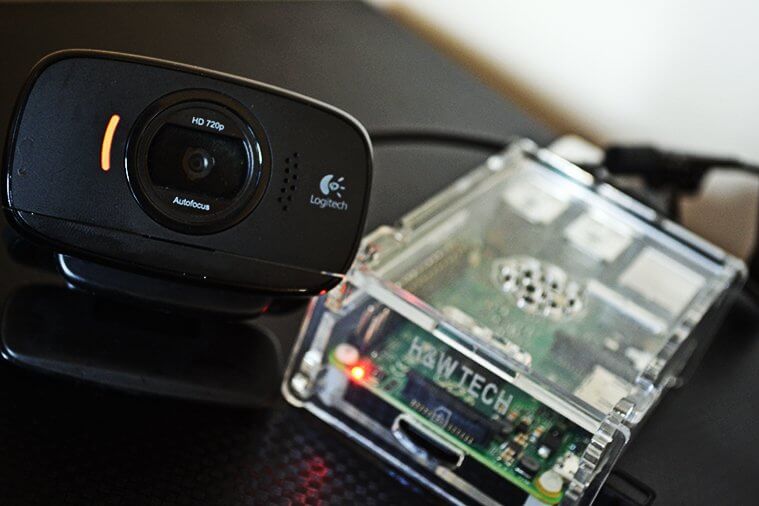
Pi My Life Up
Learn How to build a Webcam server on the Raspberry Pi.
this shows a way to do it
don't know how updated it is
but i would never do this
cold monolith
uncut lagoon
https://pimylifeup.com/raspberry-pi-webcam-server/
Are you sure you're aware of what he's asking? Seems like he wants to run a server on the web, and use the pi as a client, forgoing the need to port forward
echo hare
uncut lagoon
but i would never do this
why ?
cold monolith
Because in that link the pi is the server, which means you need to open ports on your local network, if you are sending to web use the pi as a client not a server
uncut lagoon
... send the snapshot from the raspberry pi camera to the web.
^ this is what was asked
cold monolith
Okay, where in the web? You didnt ask
echo hare
cold monolith
Okay, where in the web? You didnt ask
ı wanna see oly local port .
only*
cold monolith
What are you trying to do? send the video to a server or another computer on another network directly?
echo hare
uncut lagoon
https://pimylifeup.com/raspberry-pi-webcam-server/
If this link is up to date this is exactly what I want
uncut lagoon
it seems to work, i never tried
just don't do the "access from outside"
you can ignore that part, and be done
echo hare
cold monolith
What are you trying to do? send the video to a server or another computer on ano...
I want to send it locally and see it on the web on another device over the same local.
uncut lagoon
when you say "on the web"
some people (me) may interpret as "outside my network", which is "the internet"
like, you're in a coffee shop and want to see the webcam, and you access it from there
echo hare
uncut lagoon
some people (me) may interpret as "outside my network", which is "the internet"
oh okey , ı dont wanna outside my network now
uncut lagoon
im sorry if that caused confusion, but it really wasn't my intention
cold monolith
Also, for future reference you can get around port forwarding by using ngrok as long as you trust the video streaming server
echo hare
uncut lagoon
https://pimylifeup.com/raspberry-pi-webcam-server/
If this link is up to date, it will work for me
uncut lagoon
cold monolith
Also, for future reference you can get around port forwarding by using ngrok as ...
i didnt knew that
echo hare
uncut lagoon
saying it works
I'll try it soon. I write the result
echo hare
uncut lagoon
i didnt knew that
me too
uncut lagoon
i was thinking about no-ip or similar instead of ngrok
cold monolith
I find ngrok so handy I pay for it so I can have reserved DNS
cold monolith
uncut lagoon
i was thinking about no-ip or similar instead of ngrok
Hm, another reverse proxy+dns service?
There are quite a few, ngrok is just too easy to setup on a pi
cold monolith
Ah, then not really the same thing
uncut lagoon
it is, it's a dynamic ip service
you get an url, and it points to you ever-changing ip
but on the router, you don't need to setup anything on any device
cold monolith
Ah alright, ngrok doesnt support a lot of devices, you'd need to be really tricky. This is just I want to access this one port on my pi from a domain remotely
uncut lagoon
the alternative could be a vpn with a mikrotik device
cold monolith
Sure, just then you need to add external clients to said VPN, which may be desirable if one wishes for decent auth
You are the only person I have ever heard mention mikrotik 😆 I just got a new lorawan gateway from them
uncut lagoon
my friend works with their stuff
and from what he said, mikrotik has a free dynamic dns service
and their switches are good enough to make a vpn
so, why not?
besides, making a vpn will give access to everything inside
and it isn't that hard to add users, with some googling
cold monolith
No, but if I want to view my webcam from anywhere and nothing else, running one command on one pi can be nice. Sometimes a VPN is overkill, but I agree its a better solution
uncut lagoon
seems like that AtesliPanda is a tinkerer, so, a vpn may be a better/worse idea (depending on how secure it is)
for this exact project, it doesn't seem necessary and the guide covers everything
echo hare
uncut lagoon
seems like that AtesliPanda is a tinkerer, so, a vpn may be a better/worse idea ...
it doesnt work 😦
uncut lagoon
you're welcome
ionic stag
So, what would be a reason for a Raspberry Pi Zero not loading even with a known good sd card with Raspian? I tested the 5v and 3v3 pins and they're stable. I also get the Boot thingy when I plug it into my computer without an sd card in it
The ACT light blinks once or twice then remains on constantly
 paper compass
ionic stag
So, what would be a reason for a Raspberry Pi Zero not loading even with a known...
paper compass
ionic stag
So, what would be a reason for a Raspberry Pi Zero not loading even with a known...
So the SD card was just flashed with Raspberry Pi Imager, you allowed it sufficient time on first boot to resize the filesystem and reboot (failing to do so can corrupt SD), and you boot again and what happens? Do you have a monitor hooked up?
 strange mulch
Am I able to use a raspberry pi 3b with the bluefruit connect app?
ionic stag
@paper compass What is considered sufficient time? I waited about 10 minutes before replugging it the first time. Should I've waited longer?
Also, I planned to run it headlessly and don't have a way to check video because I don't have a microhdmi to hdmi
paper compass
I normally use the raspberry pi headless. So how do you know it's not working then? Have you added an empty file on the SD card called ssh to enable SSH? and used a wpa_supplicant.conf file to configure wifi?
And yes, 10 minutes should be enough
ionic stag
Yup
I had the ssh file and the wpa_supplicant in
Is it possible to have the Pi zero log to the boot part of the sd card?
the ssh and wpa_supplicant files seem to be consumed, they aren't on the sd card boot partition anymore
ionic stag
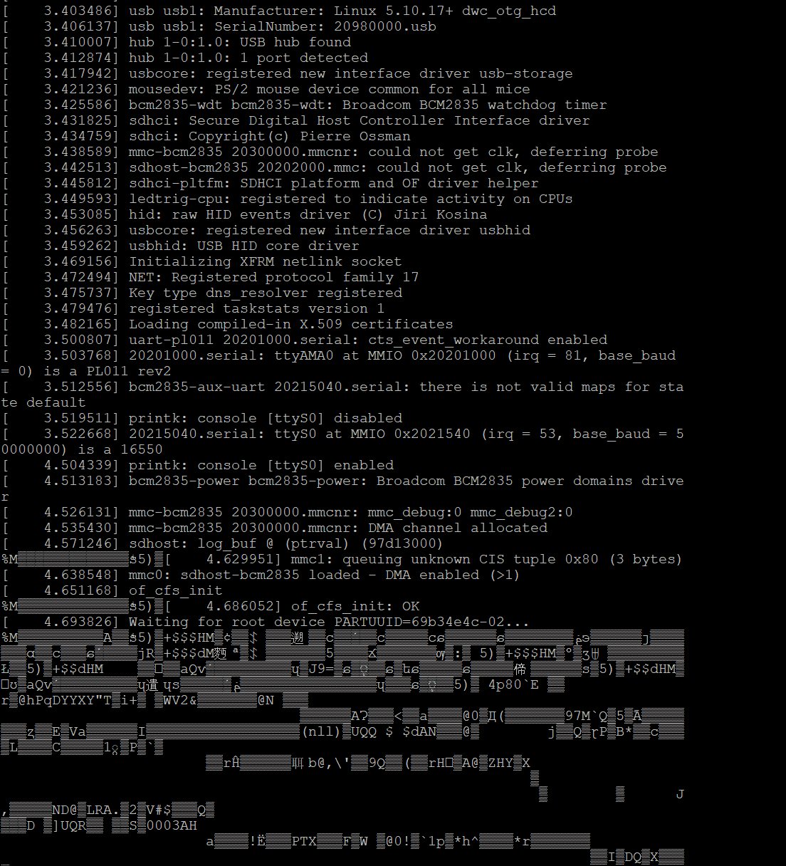
I tried using my Pico as a Serial bridge since I lack one and it was going normally then just went crazy from earlycon https://prnt.sc/12z0mms
 paper compass
Ya that sounds about right, I think the ssh and wpa files are consumed if parsed. Have you tried SSH to raspberrypi.local?
That's pretty much my standard approach. Flash fresh SD with Raspberry Pi Imager, unmount / remount SD card, run my script that adds ssh and wpa_supplicant.conf files, wait for it to reboot twice, then run ssh pi@raspberrypi.local with password raspberry.
As for your serial console output, I can't help you there. I've never used the Pico as a serial bridge.
hardy plaza
You can also use nmap to scan your local network for IP addresses to see which devices are online. I've got a Python script that does that for me.
paper compass
Yup, and logging into your router and looking at connected wifi clients works too.
hardy plaza
paper compass
Yup, and logging into your router and looking at connected wifi clients works to...
Nice thing with nmap is you can do it from any device on your network, even your Pi.
paper compass
You didn't grab an older Pi Zero by mistake did you? I once spent hours trying to figure out why the wifi wouldn't work, and it ended up being the older version of the Pi without WiFi. I'll only made that mistake once.
hardy plaza
My script is fairly long and has YAML config, etc. but the guts of it is two lines:
command = 'nmap -sn 192.168.1.0/24' proc = subprocess.Popen([command], stdout=subprocess.PIPE,universal_newlines=True, shell=True)
Then you read the lines returned:
for line in proc.stdout: _line = str(line).strip() ...
ionic stag
I'm pretty sure its a pi zero wireless, its the only one I have and adafruit says I ordered the wireless version
And raspberrypi.local does service not found on ubuntu on WSL and nothing either from Windows 10 with Bonjour
And it wasn't on the router's list of connected clients
paper compass
If that's what you purchased I'm sure it's a Zero W then, maybe I'm the only one with random raspberry pi's laying all over the place ...
That is odd. Without including your password, can you show the contents of your wpa_supplicant.conf file?
 proper bobcat
^ Sounds like wpa_supplicant.conf is malformed or missing information.
ionic stag
country=US
ctrl_interface=DIR=/var/run/wpa_supplicant GROUP=netdev
update_config=1

network={
    ssid="kevinsnetwork"
    psk="<password>"
}
The network is wpa2-psk if thats relavent
ionic stag
Could an issue be that my wifi broadcasts 2.4ghz and 5ghz on the same ssid? Its not an issue for Pi3 B+ but idk about the zero
paper compass
well, it shouldn't see the 5ghz, are you sure your 2.4ghz network is on?
ionic stag
It is, my gateway says its broadcasting 5 and 2.4
My phone uses 2.4 and is working as well
paper compass
I asked because I think the raspberry pi 3 b+ has 5ghz
ahh well that confirms that's working, ok.
ionic stag
Does walmart sell mini hdmi to hdmi? I may bite the bullet and buy a cable
paper compass
Best Buy would be a better bet, but walmart might
raw solar
Micro Center best bet, if you have one local
paper compass
If I had a Micro Center ... I'm jealous.
ionic stag
I wish rural Indiana had a Microcenter lol
raw solar
Micro Center best toy store
ionic stag
^
narrow wave
We don't even have Micro Centre here
raw solar
404 - Micro Centre
proper bobcat
LOL, I don't think there are many Micro Center's around these days. Are there?
ionic stag
I don't think so
raw solar
There are 28 locations across the US!
Which is the most there have ever been to my knowledge
hardy plaza
No, it's a standard HDMI signal, an international standard.
ionic stag
I was asking because if there was I have a breakout board for hdmi source
hardy plaza
Somebody correct me if I'm wrong but my understanding is that the Pi is using a specific chip to generate the HDMI signals, and I would doubt there's any breakout that would have access to the information inside that chip. AFAIK, it's basically a standard Unix X windows output from the Pi's CPU, funneled to that chip, which provides the HDMI (EIA/CEA-861, I looked it up) output.
raw solar
As far as I understand, no, there's no way to get HDMI from GPIO pins without some sort of a chip to generate HDMI signals
ionic stag
Double unfortunate
raw solar
GPIO displays use SPI or I2C as far as I know
narrow wave
raw solar
404 - *Micro Centre*
Oh i didn't even notice
raw solar
Lol
ionic stag
hehe
 hasty jackal
Having trouble with raspberry pi zero w connecting to wifi on raspbian lite
Any solutions?
ionic stag
Same issue
ionic stag
I even tried using a good install from a pi 3 b+ and it didnt work
So must be a firmware thing
ionic stag
Wait can you configure that headlessly?
Like with the ssh file in boot area and such?
hasty jackal
Not sure
paper compass
@hasty jackal you've done all this? #help-with-linux-sbcs message
paper compass
whoops, wrong link
That's pretty much my standard approach. Flash fresh SD with Raspberry Pi Imager, unmount / remount SD card, run my script that adds ssh and wpa_supplicant.conf files, wait for it to reboot twice, then run ssh pi@raspberrypi.local with password raspberry.
I use raspberry pi 4, 3, and Zero headless almost exclusively.
I only ever hook up HDMI when I need some "output" but not to use the PI or program it, I always log in over SSH
hasty jackal
My pi zero is operating headless rn its just on regular raspbian
I just gave up on raspbian lite but i might try that later
paper compass
huh, I'm not sure the difference I guess.
hasty jackal
Maybe use less resources i guess im not sure if it would though anyways because its only being powered and running a program
paper compass
Oh, I always use the lite version
no-gui, didn't realize that was 'lite'
it's like guiness, you don't realize it's actually a light beer
ionic stag
So apparently Ubuntu doesn't have anything for RPI0
 primal turtle
does anyone have knowledge as to how I can boot a pi zero into terminal mode then display full screen programs without the overhead of starting the desktop environment?
hardy plaza
ionic stag
Uh
But not on a Pi Zero. I don't think it'd have enough horsepower for that.
ionic stag
Unforunate
hardy plaza
ionic stag
Unforunate
You're asking a lot of your little Pi Zero. You can just connect it to an HDMI display and it'll be fine, but that extra layer of processing is probably more than it can handle.
ionic stag
primal turtle
does anyone have knowledge as to how I can boot a pi zero into terminal mode the...
I was responding to this
Although I misinterpreted him now, in hindsight
@primal turtle Get a light window manager
Otherwise I don't know
hardy plaza
ionic stag
Otherwise I don't know
As I mentioned his request is a bit of a non-sequitor.
But we aim to please...
I do think the idea of a very light window manager is a good one. It might shock the younger folks to see what they used to look like, maybe OpenBox, or something even more minimal.
No menus, windows with single pixel frames, no shading, etc. But they run FAST.
...and anyone can install and use one on a Pi, they're all available.
Very retro.
 tired marsh
ok so I just tried and there is no issue with running pygame on a hdmi screen from a pi without a window manager
hardy plaza
I apparently don't know what pygame is then, but congratulations on finding a suitable solution!
tired marsh
it's classically used to do both games and general user interfaces
hardy plaza
Is it X?
tired marsh
it talks directly to the screen if not run in a desktop environment
hardy plaza
So no X, it's an API.
tired marsh
you can try it, run a pi with a hdmi screen with no desktop, it will show the the text login prompt, install SDL2 from there (or from ssh) sudo apt-get install libsdl2-2.0-0 libsdl2-image-2.0-0 libsdl2-mixer-2.0-0 libsdl2-net-2.0-0 libsdl2-ttf-2.0-0 libsdl2-gfx-1.0-0 that installs all of it, and pygame pip3 install pygame and then test a demo python3 -m pygame.examples.aliens
it will be small in a corner because of default values, but it will display
 waxen valve
ive also used the DRM api to render images to the screen without SDL
tired marsh
ah python3 -m pygame.examples.chimp is full screen
now I don't think I installed anything additional on that pi to make it work like that but I can't be fully sure
waxen valve
tired marsh
now I don't think I installed anything additional on that pi to make it work lik...
that kind of question is why i prefer the nix package manager over things like apt
nothing you have installed is ever available to other packages
you must define the deps on a per-package basis
so there is no chance of it randomly working because you forgot something that was already installed
it will just fail until you clearly list it
https://nixos.org/ for more info, if your interested
tired marsh
I'm 85% sure I installed it from scratch to use for Circuitpython development though
ah there's sudo apt-get install python3-pygame that might install more needed support libraries too
raw solar
waxen valve
https://www.phoronix.com/scan.php?page=news_item&px=Linux-Generic-USB-Display
So this is how I'll get to 30 monitors without a lot of DP splitters and expensive adapters
 hot oar
Hi I was wondering, does anyone know how to connect an iphone to the Raspberry Pi via Bluetooth in order to control the pi's GPIO pins from a self-made iOS app?
cold monolith
hot oar
Hi I was wondering, does anyone know how to connect an iphone to the Raspberry P...
Normally if you made your own app you interact with other bluetooth devices over GATT, you should be able to write code on the pi to act as a bluetooth peripheral and expose custom GATT services. From there you could have a single 32-bit value with each bit representing a pin on the pi you'd like to use. You can then read that state, be notified of a change from the pi, or write a new state. Could also have another value for setting each pin as an input or output
hot oar
@cold monolith do you happen to have/ know any documentation on that approach? I'm fairly new to it.
cold monolith
hot oar
<@!461746819345416203> do you happen to have/ know any documentation on that app...
Searching around there isnt a ton of easy and great docs, but I stumbled onto this https://punchthrough.com/creating-a-ble-peripheral-with-bluez/
If you dont like python, golang has a nice GATT lib for bluez as well
hot oar
Okay awesome! Thank you! I'll check it out.
twilit quiver
hi i think ive messed up my raspberry pi when trying to set up octoprint because now all my small touchscreen show is just white
 uneven tusk
hey i have a problem with my code
everytime I run it, i get disconnected from vnc so i have to restart my pi... if anyone has any ideas...
import RPi.GPIO as GPIO
import time
import board
import busio
import adafruit_adxl34x

# define the pins connected to L293D pour les moteurs
motoRPin1 = 23 #gpio23
motoRPin2 = 24 #gpio24

enablePin = 25 #gpio25

motoPin3 = 17 #gpio17
motoPin4 = 27 #gpio27
enablePin2 = 22 #gpio22

#les pins pour les deux LEDs
led1 = 19 #gpio
led2 = 26 #gpio

#Pins pour le sonar
trigPin = 8
echoPin = 7
MAX_DISTANCE = 220          # define the maximum measuring distance, unit: cm
timeOut = MAX_DISTANCE*60   # calculate timeout according to the maximum measuring distance

def setup():
    #moteur 1
    global p2
    GPIO.setmode(GPIO.BCM)
    GPIO.setup(motoRPin1,GPIO.OUT)   # set pins to OUTPUT mode
    GPIO.setup(motoRPin2,GPIO.OUT)
    GPIO.setup(enablePin,GPIO.OUT)
(the code is long, the issue is in this part)
uneven tusk
ok works now lmao
ionic stag
In the case of the Pi Zero W having a stroke, there is news! I tried using a usb data cable to SSH into it through the peripheral port and it STILL ISN'T WOKRINGGGGGGGGGGG. Starting to think my Pi died somehow, but I don't know why as I could get some earlycon through the Serial GPIOs
uncut lagoon
have you tried the basic stuff, like, a new card with a clear os?
my pi zero w stopped working once too, it looked completely dead
i found it was the 2gb card i was using
the card is fine and works on the pc, but the pi zero w is totally dead with it
ionic stag
I tried using something with a good install from a Pi 3 B+, should I wipe that card and try or would the Raspbian on that work on the Pi Zero as well?
uncut lagoon
i would assume it should work, but i dont know
have you tried powering it without a card, and see if it does something?
ionic stag
The light stays off and Windows 10 shows the BCMxxxx Boot device
If you mean not connected to a computer the light just stays off and the pi sits there doing... whatever
uncut lagoon
do you have any other card you can use? one you can start from fresh?
ionic stag
I have just two, one in a Pi 3B+ that works and the one in the Pi Zero that's having a stroke
uncut lagoon
can you get a new one? those are usually cheap
ionic stag
I'm not old enough to drive yet so I can get a new one but it'd be one to two weeks
uncut lagoon
alright, can you check the one that's having a stroke on your pi 3?
ionic stag
Sure, one minute
uncut lagoon
btw, have you checked that the power supply is providing enough power for it to boot?
steady rose
but I don't know why as I could get some earlycon through the Serial GPIOs
you're attached to the serial output here? like with a USB serial cable?
ionic stag
steady rose
> but I don't know why as I could get some earlycon through the Serial GPIOs
you...
I used a Raspberry Pi Pico and had it log to my computer, it was fine until a ways into the process where it began sending nonsense for whatever reason
uncut lagoon
🤔
steady rose
ok. suggestions above are good /easy things to try. does suspect card boot ok in another pi? and could be power related - do you know current rating for your power supply?
ionic stag
I'm using a Micro-Usb power supply from canakit for the raspberry pi, it outputs at 5v 2.5a
steady rose
should be plenty
uncut lagoon
yeah, the pi zero w needs 1.5 amps max, as far as i know
ionic stag
I'm trying the card rn but I'm having trouble getting the card out of the Pi 3B+ because I can't find my tweezers and it's embedded in something
ionic stag
Do what?
ionic stag
Well then I'll grab my hex screwdriver. Disassembly time!
uncut lagoon
yeah, the probability of your pi zero being zero-ed is non-zero :x
sorry, had to do it :/
ionic stag
xd
uncut lagoon
but seriously, you probably might be looking into a new pi zero :/
considering how cheap they are, might be worth thinking about it
ionic stag
Yeah, I'm still confused as to how I was getting earlycon though
uncut lagoon
probably it died during the time it was being used
why it died?
i dont know, and you might want to check it
ionic stag
What would I be checking for?
uncut lagoon
question 1: how was it all connected?
question 2: what else was connected? and how?
ionic stag
1: Jumper Wires to Pi Pico, Micro USB to USB A to Windows 10 Desktop
2: Pi Pico, Desktop
uncut lagoon
what did you had connected to the pi and the pico?
ionic stag
Nothing else it was just them and my Desktop
uncut lagoon
did you overclocked your pi?
ionic stag
Nope, everything was factory defaults oc wise
paper compass
oh man, still having issues @ionic stag ? make any progress?
uncut lagoon
seems like no progress was made, since it doesnt work, but things were rulled out
which may be progress?
paper compass
in my book, failure is always progress ... I should know, that's my specialty.
ionic stag
We ruled out the sd card being bad
steady rose
if you just need a quick "is it dead?" sanity check, you can try this:
https://learn.adafruit.com/raspberry-pi-zero-creation/is-my-pi-zero-dead
ionic stag
Ill try that in a bit
Its showing up in device manager
BCM2708 Boot
So it has some semblance of life
uncut lagoon
yeah, and now the 2nd step
ionic stag
Second step? Like on the adafruit page? The install os one?
uncut lagoon
yes
ionic stag
writing now using rpi imager
Written
Now what? I cant check display output on the zero because I dont have a micro hdmi to hdmi
uncut lagoon
you can use ssh as in the guide
you can configure all this from the imager
it's stupid as it can be, but, you have to press a set of combination keys to use the imager to set it all up
or follow the guide to get ssh working
and then you have to find the ip of the pi
angry ip scanner, for example, may help you
or similar tools
ionic stag
Kk I'll try that
uncut lagoon
good luck
 little nest
Good evening
ionic stag
uncut lagoon
good luck
Tried doing it myself, didn't work. Tried using the advanced menu from pi imager, also didn't work. Is it possible the wireless chip is dead?
ionic stag
This gets odder by the minute
uncut lagoon
do you have any serial output from your pi?
ionic stag
I can get earlycon but I can't get a full shell using my Pico
although that may just be a limitation Pico side
ionic stag
Do they sell those at walmart/best buy or do I have to order one from Amazon?
uncut lagoon
possibly, but they may be old outdated ones that only work with windows xp
ionic stag
Unforunate
uncut lagoon
you can try looking for it
ionic stag
Yeah I'll add it to the list. Thanks for your effort in assisting me!
uncut lagoon
you're welcome
lucid crest
I was wondering if anyone knows of a single board computer that is in the Raspberry Pi B form factor, but is more powerful that the Raspberry Pi 4? Ideally one with a dedicated/better GPU.
hardy plaza
lucid crest
I was wondering if anyone knows of a single board computer that is in the Raspbe...
How compatible does it need to be? GPIO pins match, etc?
lucid crest
Mostly compatible?
GPIO matching would be great, but could be worked around.
USB ports are optional. Ethernet is also optional.
Display port is not needed.
Camera port is definitely needed.
hardy plaza
Well, I’ve tried a number of the alternative fruit and vege Pis and you will sacrifice both hardware compatibility and any semblance of support, but NanoPi and Orange Pi make good boards, some with a B form factor. Little to no support but if you’re okay with that they are an alternative. Probably recommend Armbian for the OS. I have no experience with Pine.
lucid crest
Hmm, ok. Good to know. Thank you.
uncut lagoon
you can try the latte panda
it isn't the same size as a pi, but is a lot more powerful
and has arduino-compatible pins
so, may be usable
you may try an asus tinker board
lucid crest
Do you know if the Latte Panda can run Linux? I'm only seeing Win10 being mentioned
uncut lagoon
yes, it says on the website
it is A LOT more expensive than a raspberry pi
btw, it is an x86 pc, so, remember that too
lucid crest
I'm ok with the arm->x86 change. It's just the form factor that I was hoping to keep the same.
uncut lagoon
the asus tinker board
same form factor
the difference is the io on the left side
the display, audio and power
raw solar
Unless things have changed since I last looked into it, Tinker Board also has... lackluster support
raw solar
I kinda want a Latte Panda
lucid crest
uncut lagoon
the display, audio and power
Good to know. Thanks.
And at this point, I'm used to lackluster support 😦
uncut lagoon
i mean, they are products that didn't had that much success in sales
raw solar
One might argue that sales were lackluster because support was lackluster XD a lack of info is why I didn't snap up the Tinker Board despite the competitive price to performance vs. Pi at the time
uncut lagoon
that's an interesting point of view
i remember nvidia had some pi-like thingy with ai
i remember watching a video about it being quite powerful for emulation, but don't remember much more
raw solar
I think the Jetson had great support, I just never found time for that one
And/or money
lucid crest
So, I have a Jetson, and they've actually been really good about documentation and support
raw solar
The Jetson gets more into a niche than any of the other Pi competitors as far as I'm concerned because of the "extreme" GPU power and Tensor cores
lucid crest
Especially when they moved from the prelim versions to the official versions, they really added a TON of info for how to use it.
Yeah, that's fair.
However, because of the heavy-duty GPU, the gui is nice and snappy when using it for general purpose stuff
The only "problem" with the Jetson Nano is that they really don't want you to use the dev kit for anything product-related. And not using the dev kit is surprisingly hard to justify.
raw solar
I feel like there were more makers who scooped up the Jetson than Nvidia may have expected, lol
lucid crest
Lol, probably true
raw solar
I was thinking about grabbing one...
uncut lagoon
i mean, it did sound interesting
the ui on a pi is kinda eh
on a pi zero, it's HORRIBLE
even with ssh, it's a disgrace
but if the jetson was around the price of a pi, i would like one
lucid crest
So, honestly, I think that kinda goes with the "You get what you pay for" mentality.
raw solar
I keep waiting for my Pi Zero to explode
uncut lagoon
i was expecting it to be better over ssh
but for what i use, it's amazing
i bought a pitft for it, and wrote a gui for the console, in python
it's a huge mess, but it works
uncut lagoon
i have the 240x240 one
i've actually been trying to find ways to reduce the import times, as it can take over 5 seconds to import a bunch of libraries that i need for it
raw solar
I ordered... uhh... checks notes 135x240 and 240x240
uncut lagoon
will you use it with pigame (or whatever the library is) or kernel mode for the console?
uncut lagoon
nice
lucid crest
raw solar
I wanna make a pocket dynamically generated text adventure game
Sounds like a pretty fun project.
raw solar
Hopefully it will be XD
lucid crest
And that too! (Sorry, clarified my message with an edit)
raw solar
Hehe
uncut lagoon
will you do it all on the console?
raw solar
Yeah, I think I can do it without leaving the console :D
uncut lagoon
that will be a challenge, but can be done
btw, word of advice
set the console text to a smaller size, to get readable text but more chars on screen
i've used a 5x8 font or something
raw solar
Yeah, gotta have enough room to get a paragraph description XD
uncut lagoon
on debian, it flops between whatever size it decides
raw solar
oof
raw solar
Probs gonna be Raspbian without the GUI
raw solar
shrug
uncut lagoon
but it's fun working on those
raw solar
I wonder if you can do 2 TFTs at once...
uncut lagoon
you cant
raw solar
phooey
uncut lagoon
it will cause issues with the framebuffer, as far as i know
raw solar
hmmmmmmmmmm
uncut lagoon
besides, i dont think you have enough power and gpio for both
and dont even think that the driver can support both
raw solar
They don't use much power or that many GPIO pins
uncut lagoon
yeah, but the software side is very tricky
raw solar
software hard
uncut lagoon
very
raw solar
Hardware harder
uncut lagoon
eh, hardware will do what the software tells it to
i think you might be able to control the 2nd display with python
hardy plaza
I believe the Pi TFTs are SPI devices, so if you’re not plugging directly into the GPIO pins it might be possible to set up two on separate SPI buses and deal separately in software. Otherwise there’d be both hardware and software contention
raw solar
Hmm... I'mma have to research
uncut lagoon
i think the kernel driver can only handle one
but with python, you might be able to use both
raw solar
Probs python then
uncut lagoon
the question is: how will you connect both?
raw solar
Solder and wire?
uncut lagoon
yeah, you will have to connect both outside the pi
also, if you use 2 240x240, you really have to put the 2nd outside, somehow
and the header is actually really thin
raw solar
Hmm
uncut lagoon
you see the back of a gpio pin header?
that's roughly the height of the connector on the display
raw solar
Yeah