#help-with-linux-sbcs
1 messages · Page 12 of 1
 tired marsh
 midnight stone
that's all i've got on the server properties stuff

 opaque wagon
on a different computer, try going to the inet address (192.168.1.133) in a browser
opaque wagon
could you post your code between backticks like this:
```python
code here
```
becomes:
# code here
if it's large do a pastebin/gist and link here
midnight stone
from http.server import BaseHTTPRequestHandler, HTTPServer

hostName = "127.0.0.1"
serverPort = 8080

class MyServer(BaseHTTPRequestHandler):
    def do_GET(self):
        self.send_response(200)
        print(self.path)
        #if self.path == "openGate"

if __name__ == "__main__":
    webServer = HTTPServer((hostName, serverPort), MyServer)
    print("Server started")
    try:
        webServer.serve_forever()
    except KeyboardInterrupt:
        pass
    webServer.server_close()
print("Server stopped")```maybe change the hostName to 0.0.0.0?
midnight stone
i had it at 0.0.0.0
opaque wagon
127.0.0.1 tells it to only serve on localhost
opaque wagon
what did you change?
midnight stone
changed it from 127.0.0.1 to 0.0.0.0
opaque wagon
ah good it works on other computer now?
midnight stone
yeah
opaque wagon
nice! if you have any other problems just ask here again - this community is very nice
midnight stone
alright
 wise sonnet
So I’m using a Pi ZeroW to generate a control signal for a brushless motor and ESC. Doing it in circuitpython with pwmio. With the raspberry, the pwm signal is very jittery around its set value. I tried with a microcontroller and it’s rock solid - so I don’t think it’s anything downstream of the control signal. I oscilloscoped the pwm signal and I can see duty cycle jumps around a bit directly when it’s being generated by the Pi.
Does this just come down to Pi’s not being ideal for real time applications? That’s why the microcontroller works fine? Or is it something else? I want to control over WiFi and while that’s possible on Microcontroller of course, it’s trivial on a Pi (and that’s what I have on hand) - that’s why I’d like to use that if I can.
I guess a more succinct question is: is a raspberry pi equally good at generating a pwm signal as a microcontroller? Not sure what goes on under the hood myself to know.
opaque wagon
wise sonnet
I guess a more succinct question is: is a raspberry pi equally good at generatin...
Usually the PWM done by a Pi would be done in software and Linux can't guarantee a task to run so the pulses will most likely not be smooth. On a microcontroller, usually an timer is dedicated to the PWM so it's basically super accurate.
wise sonnet
@opaque wagon , thanks! I had a feeling it might be something like that - guess I’ll stick with a feather
 hybrid vortex
wise sonnet
<@633764848924229635> , thanks! I had a feeling it might be something like that ...
hybrid vortex
wise sonnet
<@633764848924229635> , thanks! I had a feeling it might be something like that ...
You can get the best of both worlds by connecting the feather to the pi and letting the pi tell the feather what pwm signal to output
opaque wagon
IMHO, it would be easier to buy like an Adafruit AirLift Featherwing for the Feather as there are very nice APIs and you don't need to wait for a Pi to boot, worry about file system corruptions, etc.
wise sonnet
@opaque wagon @hybrid vortex the Raspberry Pi 5 with an on-board RP2040 will be a nice upgrade 😛
hybrid vortex
It definitely would
I feel there is a good chance for it happening as the rp2040 was designed around having very flexible and powerful io
wise sonnet
for sure
 wraith grove
rapsberry pi pico, pin 15, do not use, has a special purpose
I feel awkward yakking about a microcontroller here, but there I go
what is the special purpose of pin 15 that must not be said in the first few google search results I tried?
several demo projects seem to use that to blink a LED, so I'm not gathering it is as bad of a line of thought as "why should I waste two buckets when I can fit my matter and antimatter in one?"
 finite bay
Who says it has a special purpose?
wraith grove
"You get a total of 25 GPIO pins (technically there are 26 but IO #15 has a special purpose and should not be used by projects)" -- Adafruit product 4864
their pinout card also says "DO NOT USE ->"
more digging,
"GP15 should not be used, it is used by the internal USB peripheral" -- ladyada
finite bay
Interesting, since the official datasheet / docs don't mention anything about this.
wraith grove
I'm now gawking at https://github.com/adafruit/circuitpython/issues/4034

GitHub
CircuitPython version: 6.1.0-rc.1-51-gfb1e0106b dir(board) yield the output of: ['class', 'A0', 'A1', 'A2', 'GP0', &a...
hybrid vortex
It’s a bug with how it interacts with USB I think
Something like that or the startup process if I remember correctly
wraith grove
page 642, RP2040-E5
https://datasheets.raspberrypi.org/rp2040/rp2040-datasheet.pdf
finite bay
Well, there you go 😄
wraith grove
still pondering why the earth is not covered in anitmatter explosion marks, lots of examples use that pin
finite bay
It's always fun when a chip has a bug but existing applications depend on this bug, and so it will either never get fixed, or when it gets fixed everything breaks 😉
midnight stone
weird for some reason only 2 out of 4 pins that i have easy access to wont drive the relay

using a raspberry pi zero W
and by wont drive i mean
the relay wont open after being closed
or other way around idk the technical terms
the TxD and RxD named pins work fine
midnight stone
ill jsu switch to different pins
 balmy niche
does anyone know if it is possible to use a raspberry pi zero as a usb audio device?
 fresh trench
@wise sonnet https://www.codecubix.eu/linux/hardware-pwm-with-raspberry-pi-zero/ I presume the GPIO pins you can use for hardware DMA are in use for something else?
wise sonnet
fresh trench
<@!248264531606765568> https://www.codecubix.eu/linux/hardware-pwm-with-raspberr...
I’m using GPIO18
Here’s the issue to maybe explain better than my text
You can see how jittery the duty cycle is
fresh trench
which os
wise sonnet
Raspbian Lite
fresh trench
I think given the default scheduler in all of those distros is for general purpose, they will never give us the level of control on the rise/fall edges we want in software. its always going to preempt for things we dont care eabout. Id wager the real time kernal is not up to par with the mainline tree on these devices yet, but using a RTK with a single use focuse scheduler might help.
custom built gentoo, in other words, with zero fluff
wise sonnet
Thanks! I have a feather laying around too so I think I’ll just use that though
This is the first time I ever bumped into this as a practical issue. I’d heard people say “watch out” for these cases before
fresh trench
welcome to the jungle, we got fun and games 🙂
 mint leaf
I need a lot of specific help with raspberry pi integration with Adafruit’s RGBW NeoPixel strips. I’ve made a lot of progress, but I am stuck on the flickering issue. Who can I talk to for help?
 umbral sable
Pretty much everyone here is just an enthusiast or a volunteer, so you'd want to just explain what you've done and what problems you're seeing. Trying to reduce it to the simplest case that still causes the issue is often useful.
hybrid vortex
mint leaf
I need a lot of specific help with raspberry pi integration with Adafruit’s RGBW...
Because raspberry pis run a non real time os driving neopixels can be difficult
Often when I use neopixels I will use a microcontroller to drive them as they handle the timing requirements much better which might help with the issue
wraith grove
way above my pay grade, but suddenly wondering how hard it'd be to tell linux to leave a core alone to run its own bitbanging daemon
actually, you can largely tell it to leave a core alone and that a program can stick to one core, not sure how much that would help, but, thats a thing
hybrid vortex
I feel it would be much easier to add a low cost microcontroller to deal with it as modifying the linux kernel to do that sounds difficult
You will need to make lots of changes to the scheduler to make it closer to how rtos works
wraith grove
if it is the only program on the core, I'm wondering of the scheduler will get in the way all that much
set it to "not very nice at all" and tell everything else to attempt no landings there :-)
mint leaf
So, I have a microchip running animations for the lights, but I still want to set colors from a raspberry pi. Single output and done is all I’m looking for... solid colors. Someone in another thread online mentioned blacklisting the audio kernel module as a fix... but I can’t find any information as to how to do this.
mint leaf
Okay, I think I figured out the blacklisting and it didn’t work. Here is my next question... I have a raspberry pi 4, and I will be running the lights off an Arduino Leonardo. Is there a way to se my color value for solid colors to the Arduino?
mint leaf
Never mind, I think I found a solution. In frustration, I just grabbed a bunch on grounding wires and grounded and double grounded things... and then it worked. Some days, I just don’t understand electronics...
 strong topaz
(Cross-posted from help-with-audio): I have some ICS41350 MEMS PDM mics and would interface to RPi 3B. I know the Broadcom chip has built-in PDM support -- does that include built-in decimation and LPF? Or do I need to implement that in software?
 waxen valve
wise sonnet
You can see how jittery the duty cycle is
waxen valve
wise sonnet
You can see how jittery the duty cycle is
if you want the jitter to go away, you must use the hw pwm, not the software pwm
wise sonnet
waxen valve
if you want the jitter to go away, you must use the hw pwm, not the software pwm
I thought all I had to do for hardware pwm was just use GPIO18
waxen valve
you must use the pwm peripheral
a random hit from google: https://www.raspberrypi.org/forums/viewtopic.php?t=194839
leads to docs at http://abyz.co.uk/rpi/pigpio/python.html#hardware_PWM
and an example of:
import pigpio
import time

pi = pigpio.pi()

pi.hardware_PWM(18, 38000, 300000)
Lol nice that’s the same hit I just came back here from. Good to know, will try it out! Thanks
strong topaz
Hmm. To re-cast my question: has anyone interfaced PDM mics to an RPi 3? I've already got I2C working, but need to switch to PDM...
 solemn finch
ladyada said on ask an engineer tonight that an I2S mic is the way to go with RPi
strong topaz
Yes, but...the I2S mic is frequency limited. The PDM mics are the only way to go if you want to listen to bats and other ultrasonic sounds...
I've seen one recipe for tweaking the RPi kernel to switch from I2S to PDM, but wanted some consensus on how to do it.
 faint sparrow
Hi guys, I just saw a video about the CrowPI - A Raspberry Pi built into a small hardcase along with a range of peripherals to interact with.
As a linux and python nub this looks like an awesome way to learn - Not too expensive either, but I wonder, are you aware of a somehow better product out there?
 molten glen
trying to install alexa services on my rpi b+ and it keeps freezing
using this guide https://developer.amazon.com/en-US/docs/alexa/avs-device-sdk/raspberry-pi-script.html#step-2-download-and-install-the-sdk
wasting a lot of time if i keep having to unplug it, reboot and enter sudo bash setup.sh config.json [-s 1234] to resume the installation.
temperatures are fine it doesnt go past 25c but CPU usage is way up at 100 constantly causing my VNC client to disconnect

im going to have SD card issues again if i keep powering it off by yanking the cable out
umbral sable
Maybe use nice to run the installation at a lower priority, or use a simple ssh terminal instead of VNC?
molten glen
umbral sable
Maybe use `nice` to run the installation at a lower priority, or use a simple ss...
how do i use nice?
ssh freezes as well
think its because i have it idling for too long
thats why i used VNC instead
umbral sable
That's unexpected. Something in the install script might actually be crashing the Pi.
molten glen
 umbral sable
Or maybe purposefully rebooting it?
molten glen
done that 20 times
umbral sable
I'm a little suspicious of the 25C temperature reading, as that seems pretty low even for normal idle consumption.
Maybe consider underclocking the processor temporarily?
molten glen
now that im ssh'd in what can i do when it freezes

rebooted and used nice in 10 before the install script command hopefully that helps
connection was reset see this is what i mean
ssh keeps disconnecting and now i cant get back in it says timed out!
pinging it doesnt go through, plugging in hdmi and keyboard and its still unresponsive.
increased my swap on size to 4GB gonna see if that helps, after this i will underclock.
umbral sable
My best guess at this point is that the temperature sensor is not working correctly, so the processor is continuing to run flat-out and eventually overheats and crashes, instead of knowing to throttle itself back. So hopefully underclocking would help it keep cooler. Obviously if you have a fan or heatsink, that might also help.
Maybe see if there's a build option to run on only one core instead of multithreading the compile?
molten glen
ITS WORKING!
increasing the swapon size helped!

it was a memory issue according to github
molten glen
umbral sable
My best guess at this point is that the temperature sensor is not working correc...
ive felt it way hotter than this before so thats not it, there are two heatsinks too.
 worthy locust
Hi, I'm using the DC and Stepper Motor bonnet for the raspberry pi and trying to control a 5V DC motor using it. However, when I run my code, I find that the motor just sits there and makes a high pitched noise rather than actually turning. I've tried using other motors as well, ending up with the same result. Any suggestions as to why this is happening and how I can fix it? I've found similar questions online but they're mostly related to Arduino and controlling PWM. Any help would be much appreciated 🙂
Here's the code that I tried to run for reference:
I measured the voltage across the terminals of M1 using a multimeter and it seems to be around 6V. I also tried connecting an LED instead of a motor, and that worked just fine. So why doesn't the motor work properly? 😦
hybrid vortex
@worthy locust try using stepper1 instead of motor1 and motor2
And stepper2 instead of motor3 and motor4
And onestep instead of throttle
If you want to move more than 1 step you will want to put it in a loop
You can get more information about how to control steppers here https://learn.adafruit.com/adafruit-dc-and-stepper-motor-hat-for-raspberry-pi/using-stepper-motors

Adafruit Learning System
Stackable Steppers and DC motor control for your Raspberry Pi
worthy locust
Sure, I'll try it out, thanks!
hybrid vortex
worthy locust
Sure, I'll try it out, thanks!
All good, hopefully that will help. If you need any more assistance with it feel free to ask me.
 nova karma
I have a raspberry pi case (this: https://www.adafruit.com/product/4341) where the foam was damaged in disassembly. I'd like to reuse. The gap between the raised parts and the pi is too large for heat sink tape, and I'm considering using some PC CPU cooler thermal compound. Terrible idea?
 tawdry lynx
Hi! I am getting this error after trying to run the example inside Adafruit PN532;
File "readmifare.py", line 44, in <module>
pn532 = PN532.PN532(cs=CS, sclk=SCLK, mosi=MOSI, miso=MISO)
File "build/bdist.linux-armv7l/egg/Adafruit_PN532/PN532.py", line 166, in init
File "build/bdist.linux-armv7l/egg/Adafruit_GPIO/GPIO.py", line 420, in get_platform_gpio
ImportError: No module named Adafruit_BBIO.GPIO
The other example i tried worked fine actually;
https://learn.adafruit.com/adafruit-pn532-rfid-nfc/python-circuitpython
pn532_simpletest.py from the link above works totally fine and i get 'Found card with UID' successfully.
I'm using NFC Module PN532 + Rpi 4 and connect ports are SCLK=GPIO11 MISO =GPIO09 MOSI= GPIO10 CS= GPIO5
I would be very much appreciated if anyone helps 🙂 (I am not sure if i asked the question on the correct channel, warn me if its wrong.)
 marsh monolith
Hi I have a pi4 and i have a Qwiic HAT and I have the BNO085 IMU sensor i attached to the HAT with JST 4 pin cable. I would like to know how i can detect if sensor is responding ? I am a total N00b.
umbral sable
marsh monolith
Thank you. I will try that
 hearty path
nova karma
I have a raspberry pi case (this: https://www.adafruit.com/product/4341) where t...
hearty path
nova karma
I have a raspberry pi case (this: https://www.adafruit.com/product/4341) where t...
How big is the gap? Thermal compound helps in heat transmission, but it's not meant for significant gaps, as it's not that good at conducting heat
hearty path
tawdry lynx
Hi! I am getting this error after trying to run the example inside Adafruit PN53...
It looks like it's trying to use the compatibility library for the BeagleBone device, whereas you have the RPi 4. Did you install the library using pip?
tawdry lynx
hearty path
It looks like it's trying to use the compatibility library for the BeagleBone de...
Thanks for the answer! I used pip3 command to install the library indeed.
hearty path
That's quite peculiar 😕 And that was on this same device?
hearty path
Ok. I don't have that sensor, but I'm trying to reproduce the issue you're seeing up to that point
nova karma
hearty path
How big is the gap? Thermal compound helps in heat transmission, but it's not me...
hard to measure. 1 mm?
tawdry lynx
hearty path
Ok. I don't have that sensor, but I'm trying to reproduce the issue you're seein...
Is there a way that you can provide me some resources for Rpi4+PN532 with SPI? I am trying to make a small app for android phones with read and write via NFC but my documents are quite limited.
hearty path
tawdry lynx
Is there a way that you can provide me some resources for Rpi4+PN532 with SPI? I...
There is this documentation for the SPI implementation: https://circuitpython.readthedocs.io/projects/pn532/en/latest/api.html#adafruit-pn532-spi
You might want to try uninstalling the BBIO library with pip uninstall Adafruit-BBIO and add "adafruit-blinka" with pip install Adafruit-Blinka
tawdry lynx
I already have Adafruit-Blinka but i will try uninstalling and installing those asap.
Btw, i just noticed that my rpi has python 3 in it. Is there way that there is a mismatch cause this library seems quite old?
hearty path
nova karma
hard to measure. 1 mm?
Worth a try. Seems a bit big of a gap to bridge, but at the same time, the PI doesn't run so hot that it will spontaneously vaporize itself if it gets too hot
hearty path
tawdry lynx
Btw, i just noticed that my rpi has python 3 in it. Is there way that there is a...
It shouldn't be, since the library PN532 library is more about interacting with the device, whereas the underlying library, Adafruit-Blinka in this case, is what would manage the communication, and it's good to go on Python3
tawdry lynx
hearty path
It shouldn't be, since the library PN532 library is more about interacting with ...
Thank you so much.
hearty path
Were you able to get past that error?
tawdry lynx
My rpi is not in my hand at the moment 😦 and it is 03:26 AM here atm lol. Will try these in the morning and give a feedback for sure 🙂
hearty path
Yikes! Fair points. Good luck, and good night!
If you still run into issues, someone's around 🙂
tawdry lynx
It is great to hear that sir! Thank you so much again and have a good night, or a day, or whatever it is :=) Will ask more questions for sure 😄
 runic kettle
is there a proper tutorial link for raspberry pi4
 stoic finch
Cursed images incoming:


Assuming I match up the GPIO pinouts, would the above work as a sort of GPIO passthrough? I want to use the Braincraft Hat on a Pi4 but want access to additional GPIO pins and am reluctant to solder on to the board.
 ruby night
If you are planning to attach a ribbon cable to the black 2x20 header, make sure you have the "key" on the correct side. It looks to me like it is reversed in your picture -- Pin 1 of the header should be 3.3V - the "key slot" should be on the 3.3V side.
ruby night
another simpler solution is to use one of these https://www.adafruit.com/product/2223 - I have used it with other hats (I have not actually tried it with a Braincraft) The long pins should pass through the Braincraft header and allow access from the top of the board.

Connect your own PCB to a Raspberry Pi B+ and stack on top with this normal-height female header with extra long pins. The female header part is about 8.5mm tall, good for small HATs ...
runic kettle
guys please help me, i need to control my LED connected to GPIO pins on my Raspberry pi 4 by google assistant, searched some on google nothing seems to work fine
runic kettle
my script says connected and turns on the relay , but i cant turn off or on through adfruit
 tawdry lynx
I have managed to create some small projects using PN532 NFC Module with a Raspberry pi 4 to read and write to MiFare cards but i need to do it on android smartphones. Yet, i couldn't find any examples or documentation related to NFC read/write to smartphones. Can anybody help?
 mystic thistle
I am soooo confused! I have been googling for the best way to connect pi units via bluetooth. They all have built-in hardware and I am using the Raspbian buster lite. I have read that the lite version has an issue directly out-of-the-box with using bluetoothctl. I had to add pi to bluetooth.
Then I see that using the hci0 and hciconfig is another way.
Then I see the bluetooth wrapper on git.
This has confused me as to what is the best way to ensure that bluetooth is running after boot on each pi.
I want to script one of the devices to be a 'server' and the others as 'clients'. So that the server can send, redirect, and receive messages.
What is the best way to script bluetooth?
 final solstice
TLDR; will CircuitPython still work with Blinka on my Pi 4 if I’m running on Ubuntu rather than Raspian?
Hello, I am trying to plan out my next robotics project. I’m hoping to build it on the ROS2 framework.
ROS2 requires Ubuntu and doesn’t fully support Raspian. Will CircuitPython with Blinka work on the Pi4 with Ubuntu? Are there any considerations?
final solstice
faint sparrow
<@!441385031106166794> Just try it.
Thanks. I’m in the architecture planning stage for my next robot project and I’ve never used an RP nor ROS and I’m a noob with Linux, so I’m trying to get past as many of the “is this wrong or a terrible idea” before I start tinkering.
For example, I’m watching a James Bruton video and I see he uses an arduino to control his components and then that talks to the RP over UART
faint sparrow
I was pleasantly surprised to find that 99 percent of my Debian (AMD64) skills work in Raspbian.
For all intents and purposes (save a few; there's always a gotcha I suppose) Raspbian and Debian are about the same.
Ubuntu is mostly Debian. Anything good the Ubuntu team comes up with probably makes it into a later Debian release.
 modest dune
@final solstice When you run Blinka on a Raspberry Pi, either under Ubuntu, or Rasbian, you are running full Python 3.7 or latest, not CircuitPython. Blinka is a library interface that allows all the Circuitpython device drivers to run under full Python. In general, it works fine.
When you run Ubuntu, you may have to adjust some of the I/O permissions to permit the I/O access.
mystic thistle
What is the correct way to script bluetooth for RPI0, RPI3, RPI4 with embedded BT?
solemn finch
We use bleak to do BLE from python. (You can use CircuitPython's BLE libraries via Blinka BLE)
mystic thistle
@solemn finch thanks. I am in information overload. Just need a single direction to go.
solemn finch
what are you trying to do over bluetooth?
mystic thistle
I am trying to configure 2 RPI0, a RPI3 and RPI4 to communicate remote procedure calls and offloading compute from the RPI0s to the 3 and 4.
AI is the more important of it all, but hardware status and display is the other.
I have a RPI0 that will act as a battery manager. This provides a UI on a 1.13" tft display also will respond to command to shutdown the other RPIs when the operator request it.
solemn finch
I'd recommend using ethernet or wifi to do that. BLE has low data rates
mystic thistle
@solemn finch I think I will look into WIFI for Pi-to-Pi communications. Thanks
molten glen
https://acaird.github.io/computers/2015/01/07/raspberry-pi-fsr trying to do exactly this but the difference is i have a pi cobbler plus (shaped like a T not the one used in this guide)
does it matter how i position the MCP3008 chip? the side with the dot is facing the cobber.
 steady rose
the dot indicates where pin 1 is on the MCP3008
so just need to use that to make sure the correct pins get connected
molten glen
i dont have enough space on my breadboard to put the fsr there

the green dots near each component, are those unavailable for the FSR to be placed there?
steady rose
green dots in that fritzing diagram?
molten glen
yes
on another diagram they have placed this wire 3 down, does that matter?

can the wire be placed anywhere near 3v3 as long as its on the line?
 molten glen
molten glen
molten glen
my setup looks like this but the breadboard doesnt extend pass the mcp3008
steady rose
fritz is using those green dots to indicate breadboard "rows" that are used
molten glen
oh okay
steady rose
see here for a general desc:
https://learn.adafruit.com/breadboards-for-beginners/breadboards
the idea being that once something is connected to a given location, everything on the breadboard connected to that location shows the green dot
just so you know something is connected
in terms of how breadboards are arranged - see above guide
i think knowing that will help understand what fritz is doing
that red wire - it could have gone in any of the 4 locations
molten glen
steady rose
that red wire - it could have gone in any of the 4 locations
thank you
steady rose
 molten glen
can i put another component behind that red cable if i have the space? or will that interfere
steady rose
all those breadboard holes in the red rectangle are connected
not sure what you mean by "behind"
molten glen
so i couldnt put my FSR in any of the green holes here aww man

ill send pic of my setup
steady rose
in general, correct
you could do something like this maybe

but would want to move the resistor leg also
molten glen
where can i put the FSR?
 molten glen
steady rose
but would want to move the resistor leg also
molten glen
steady rose
but would want to move the resistor leg also
break the leg off the MCP3008 chip? sure i can do that
already bent 2 lol
molten glen
gonna order another breadboard now
steady rose
one of these:
https://www.adafruit.com/product/239
this is another nice option:
https://www.adafruit.com/product/942
^^ i have a couple of pi's setup with that to use for testing
steady rose
you might be able to get the FSR in on that setup
steady rose
 molten glen
FSR wont reach those two holes
https://www.amazon.co.uk/gp/product/B07K8PQ4B5?psc=1 ordering this
is there anything else i should get for future projects?
steady rose
what do you have in the way of jumper wires?
molten glen
dont have any jumper wires just ordinary breadboard wires
im following this guide to get an output from the FSR https://acaird.github.io/computers/2015/01/07/raspberry-pi-fsr
ordering the big breadboard now that should also let me position the FSR like the person in this guide has
placing it sideways is stronger, the way i was placing the FSR you could yoink it out easily.
steady rose
probably same thing "breadboard wires" = "jumper wires" = "hookup wires"
various names
but worth having a nice stash of dedicated wires of various lengths and colors
molten glen
i ordered this electronics kit that comes with a bunch in various sizes
steady rose
yep. those.
cobbler...full sized breadboard...jumper wires...
that should be good to get you started at least
molten glen
got it
faint sparrow
Why can i not use commands on my pi zero, Ive connected over SSH using usb OTG

am i doing somthing wrong
omg nvm im dumb there was no files in that directory
hearty path
faint sparrow
Why can i not use commands on my pi zero, Ive connected over SSH using usb OTG
The call to subprocess.run() probably isn't capturing the command's output, either to stdout or stderr.
D'oh! It's always the simple explanations!
faint sparrow
yea i got it, Ive never used ssh before, its just that the pi put me into the home/pi directory by default and i thought no commands were working
i thought ls wasnt working
hearty path
Gotcha. SSH is nice - it's like a command line version of remote desktop. Except secure, and been around for much longer
 floral fjord
I installed a Pi inside of my 3D Printer without remembering that a metal case = bad WiFi haha
I bought myself a compatible USB dongle with a big antenna, I'm hoping the larger antenna helps with the metal case but if not, the antenna is removable so I can always panel mount it with an adapater so the antenna is outside
Is there a way to tell the Pi to use the WiFi Dongle instead of the onboard through SSH?
I'm unsure which one it's going to be using without me specifying
I got it
$ echo "dtoverlay=pi3-disable-wifi" | sudo tee -a /boot/config.txt
Didn't know you could do it like that

Hmm, maybe not as simple as I thought, any idea what I'm doing wrong?
hearty path
Are you trying to add the content dtoverlay=pi3-disable-wifi to the /boot/config.txt file?
hearty path
What you can try is doing an output redirect, instead of using tee. Something like this...
sudo echo dtoverlay=pi3-disable-wifi >> /boot/config.txt, which will append dtoverlay=pi3-disable-wifi at the end of the file
 echo hare
hi everyone, i need to run it with raspberry pi with ph sensor. I could not find the required library. Can anyone help with the DFRobot ph sensor
faint sparrow
~~Hey all, I am trying to get data using a barcode scanner and a python script, but when I run it, all it does it write the barcode, it doesnt seem to read it from the /dev/hidraw0... I am using this to get the data: https://bin.charles-bot.com/iwudawexoy.py~~
faint sparrow
~~I just tried this one as well, but again nothing. I tried making it output using a print() rather than keyboard.write but nothing showed... https://bin.charles-bot.com/yewozodeyi.py~~
faint sparrow
nvm got this to work, only issue I'm having now is its printing the barcode twice... because it writes it as keyboard and from the print(), so is there any way I can disable the keyboard input?
 novel mist
Hey alll,
I need some help.
I am connecting to the raspberry via xrdp, so remote desktop.
If I want to run a Thonny as an admin from the command line, it is not running, I just got an error...
is there a solution for that?
 novel bay
Has any one used minty boost with the Pi Zero W

The world's first and only open-source hardware charger: The MintyBoost®!New version! Works with the new iPhone 4 & 5 and more! Please review the Minty Boost project page(s) ...
I can't seem to find the best way to power a Pi Zero W in a way that I can carry it around, yet it doesn't add a lot of weight to it.
Wanted to even add a e-ink or TFT display if required, but yet again unable to understand the voltage / amp requirements and suitable power supply for the same, when not connected to a wall socket
 fast tapir
novel bay
I can't seem to find the best way to power a Pi Zero W in a way that I can carry...
fast tapir
novel bay
I can't seem to find the best way to power a Pi Zero W in a way that I can carry...
This looks relevant: https://www.hackster.io/news/pisugar-is-a-compact-battery-solution-designed-specifically-for-the-raspberry-pi-zero-416b503732e6

Hackster.io
The entire appeal of the Raspberry Pi Zero and Zero W is that it’s a complete, fully-functional computer in an extremely small package…
molten glen
@steady rose my breadboard arrived an i wired everything like the image on this guide shows https://acaird.github.io/computers/2015/01/07/raspberry-pi-fsr however im getting no output from the FSR.
SPI is enabled in raspi-config and here is my code
import time
import busio
import digitalio
import board
import adafruit_mcp3xxx.mcp3008 as MCP
from adafruit_mcp3xxx.analog_in import AnalogIn

# create the spi bus
spi = busio.SPI(clock=board.SCK, MISO=board.MISO, MOSI=board.MOSI)

# create the cs (chip select)
cs = digitalio.DigitalInOut(board.D22)

# create the mcp object
mcp = MCP.MCP3008(spi, cs)

# create an analog input channel on pin 0
chan0 = AnalogIn(mcp, MCP.P0)

print('Raw ADC Value: ', chan0.value)
print('ADC Voltage: ' + str(chan0.voltage) + 'V')

while True:
    # hang out and do nothing for a half second
    print(chan0.value)
time.sleep(0.5)``` steady rose
can you post photo of actual setup?
molten glen
oh just realized i could be looking at the wrong channel on the chip!
nope, the channel is correct its 0.
ill send a pic now

 balmy bronze
@molten glen [you were briefly muted due to sending multiple messages in a short period of time, you may need to repeat something you said]

 steady rose
one thing right off - your breadboard has split power rails, just something to be aware of
molten glen
ohno
molten glen
steady rose
one thing right off - your breadboard has split power rails, just something to b...
is that interfering?
steady rose
don't think so for your current setup
see how the red/blue lines don't run the full length of the breadboard? there's a gap mid way?
steady rose
the lines indicate what's connected
you can use them however
just realize that they don't run the full length of the breadboard
molten glen
yeah
steady rose
only half way
that trips a lot of people up, as full length is more typical
for your other wiring, check per here:
https://learn.adafruit.com/mcp3008-spi-adc/python-circuitpython#python-computer-wiring-3006474-4
doesn't look like you are on the SPI pins
novel bay
fast tapir
This looks relevant: https://www.hackster.io/news/pisugar-is-a-compact-battery-s...
Thanks simonc!
But I've already seen the project, and they don't ship it to my country :'3
faint sparrow
Does anyone know the total height of a raspberry Pi 3/4 with a 2.4 piTFT hat
 mystic arch
hey guys do anyone have idea how to connect 3.5 inch lcd to rpi and a motor and a led
mystic arch
molten glen
how to draw these can anyone tell me please
molten glen
mystic arch
how to draw these can anyone tell me please
software called frizing
mystic arch
do i need to download the software or it's web version is available
molten glen
dont know i havent used it
molten glen
steady rose
for your other wiring, check per here:
<https://learn.adafruit.com/mcp3008-spi-a...
wiring it properly now, how do i access the MISO pin and D5?
MCP3008 CLK to Pi SCLK
MCP3008 DOUT to Pi MISO
MCP3008 DIN to Pi MOSI
MCP3008 CS to Pi D5
Theyre the same https://pinout.xyz/pinout/pin21_gpio9#
The comprehensive add-on boards & GPIO Pinout guide for the Raspberry Pi
From the imagine it looks like I need to connect the MCP3008 CS to GPIO 6
Think I've resolved it now, code says cs = digitalio.DigitalInOut(board.D22) and D22 is GPIO 25 so the MCP3008 CS pin goes there :)
molten glen
Stuck again, wired everything except the FSR now trying to find out how to do that.
ITS WORKING!!!
steady rose
@molten glen cool. looks like you figured it out. that pinout.xyz site is a great reference, i use it all the time. the cobbler and libraries use the BCM numbering.
molten glen
steady rose
<@!816340200443740181> cool. looks like you figured it out. that pinout.xyz site...
im trying to remove all the zeros from out console output but i cant figure it out 😔
    if chan0.value >= 0:
print(chan0.value)``` steady rose
make the conditional > instead of >=
steady rose
value = chan0.value
if value > 0:
    print(value)
chan0.value is an int ive tested it
steady rose
try like that also, store the reading in a variable
otherwise you are reading twice
each call to chan0.value takes a new reading
steady rose
so the value in the conditional may not be the same as in the print
molten glen
typerror? nah
molten glen
now it fills console with 54720 🤔
 molten glen
just print(weight) inside the while spams zeros
steady rose
while True:
    weight = chan0.value
    if weight > 0:
        print(weight)
do you understand why it wasn't working before?
molten glen
print(weight) inside of the while loop only had an output of zero so ik that it couldnt reach weight = chan0.value
steady rose
i think you're seeing that assignment as sort of a mapping, or linking?
and you're expecting to be able to use weight elsewhere in code and have it provide chan0.value ?'
molten glen
yes
i will turn this while loop into a function instead and call that when i need to get the weight
going to leave it running for a few mins and see what the highest value that comes up without anything touching the FSR then compare that to weight.
trying to weigh small items like tablets/ pills with it
oh no its not as stable as i thought it would be

getting a max reading of 512 without any pressure on the FSR 😟
steady rose
the syntax may be a bit confusing, but this chan0.value is the actual "call" to get a new value, in something like arduino, that'd look more like chan0.value()
molten glen
ohh
steady rose
weight = chan0.value simply assigns the returned value from the "call" to chan0.value into the variable weight
but unless you do that again, weight just keeps the same value
don't expect "no pressure on FSR" to equate to a reading of 0
you'll need to calibrate raw ADC readings to FSR pressure somehow
and then do the math
molten glen
what is ADC?
steady rose
analog to digital converter
analog = real world values, like voltages, things that vary continuously
digital = 1's and 0's in computer land
molten glen
oh i can get voltages!

Adafruit Learning System
How to read analog signals from Python with an analog to digital converter and Raspberry Pi.
print('ADC Voltage: ' + str(chan0.voltage) + 'V')
"Returns the voltage from the ADC pin as a floating point value. Due to the 10-bit accuracy of the chip, returned values range from 0 to (reference_voltage * 65472 / 65535)"
steady rose
^^ yep
molten glen
idc about getting the value, the voltage reading would be better in this case.
 fierce spire
How can I eliminate the jittering when I control a Servo with Rasperry Pi PWM?
steady rose
is it jittering at a fixed output?
fierce spire
No I try to rotate it with the eulerangle data from the bno055 sensor so if sensor is oriented -5 degrees I calculate 90 + -5 for the angle the servo should rotate
 bright meteor
Hello, I'm having some trouble finding the IP address of my raspberry pi so I can SSH into it. I've installed the finder, but it wasn't working since it couldn't find the network.
been tryna solve this issue since a week
also the raspberry pi is connected through a wire which connects to my mac (through wifi)
@ me with answer, please
fast tapir
bright meteor
Hello, I'm having some trouble finding the IP address of my raspberry pi so I ca...
There's lots of things that can be wrong, and the networks configurations have changed a little bit over the past few years. If you're sure the network settings are correct, I'd check the syslog to see what IP address the pi thinks it has. This is what a typical reservation looks like:
Apr 15 13:10:13 debian dhclient[30411]: DHCPREQUEST of 192.168.0.181 on wlp2s0 to 255.255.255.255 port 67 Apr 15 13:10:13 debian dhclient[30411]: DHCPACK of 192.168.0.181 from 192.168.0.1 Apr 15 13:10:13 debian NetworkManager[557]: <info> [1618506613.4716] dhcp4 (wlp2s0): address 192.168.0.181 Apr 15 13:10:13 debian NetworkManager[557]: <info> [1618506613.4716] dhcp4 (wlp2s0): plen 24 (255.255.255.0) Apr 15 13:10:13 debian NetworkManager[557]: <info> [1618506613.4716] dhcp4 (wlp2s0): gateway 192.168.0.1
steady rose
@fierce spire sry, walked away. so you're feeding BNO sensor data straight into servo angle in a loop?
fast tapir
There will also be reports about things that go wrong in there. Syslog is at /var/log/syslog
Can you log into your pi over serial, or is there a UI? If you don't have anything, you can shut it down and check the syslog on the sd card
steady rose
^^ yep. that. can you get into the Pi some other way than network?
@bright meteor could also try this:
https://learn.adafruit.com/raspberry-pi-zero-creation/text-file-editing
starting with a fresh OS image. try the lite version for the sake of troubleshooting.
bright meteor
fast tapir
There's lots of things that can be wrong, and the networks configurations have c...
what is an syslog?
sorry, I'm a beginner
steady rose
system log
it logs various system level messages. some of those may contain useful information about what is happening with network setup.
bright meteor
steady rose
<@!779902922674274304> could also try this:
<https://learn.adafruit.com/raspberr...
I'll try this
okay
oh
I've already tried that
and I did those
but my code in the .conf file is different
fast tapir
How are you interacting with your pi?
bright meteor
bright meteor
but my code in the .conf file is different
ctrl_interface=DIR=/var/run/wpa_supplicant GROUP=netdev
update_config=1

network={
    ssid="wifi network name"
    psk="and the password"
}```I put a card into my pi
and plugged the pi into my mac
that's it
bright meteor
bright meteor
```country=US
ctrl_interface=DIR=/var/run/wpa_supplicant GROUP=netdev
update_con...
should i put this code instead?
update_config=1
country=US

network={
    ssid="YOURSSID"
    psk="YOURPASSWORD"
    scan_ssid=1
}```Do you have a serial cable, or any other way of logging into the pi?
It's OK if you don't
fast tapir
OK; are you editing the network config file by plugging the sd card into your computer?
bright meteor
I put in the sd card, edit it, take it out, put it in pi
steady rose
yah, try it per the guide. i think this
scan_ssid=1
line helps.
steady rose
or just try pinging it from the mac
molten glen
After connecting the Adafruit Voice Bonnet board with a GPIO header and plugging in the ribbon cable, im no longer able to get an output from the FSR.

 steady rose
ping -n 3 raspberrypi.local
how do i reboot?
steady rose
cycle power
bright meteor
🤔
steady rose
should be removing the SD card with power removed
 steady rose
@molten glen the pins are probably not making enough contact with that arrangement. you'd need to add some stacking headers.
https://www.adafruit.com/product/1979
bright meteor
what does that mean
molten glen
I used a stacking header
molten glen
its not visible in the img because of the angle
https://learn.adafruit.com/adafruit-voice-bonnet/pinouts
im already using the 5.0V, 3.3V and ground GPIO pins could that be why its not working?
bright meteor
oh no
okay so
I removed the card from the pi and put it into my mac
to check the files
but now I don't see the ssh or the .conf
they're not there anymore
is that normal?
steady rose
yep. they go away after booting.
bright meteor
alrighty
lemme try this: ping -c 3 raspberrypi.local
ping: cannot resolve raspberrypi.local: Unknown host
fast tapir
Can we try letting it run for a minute or two, then looking at the system log?
steady rose
@molten glen go back to just the ribbon cable and make sure you can read the FSR again, i.e. repeat your previous success
bright meteor
fast tapir
Can we try letting it run for a minute or two, then looking at the system log?
sure
let me wait for a minute
how do I look at the system log?
fast tapir
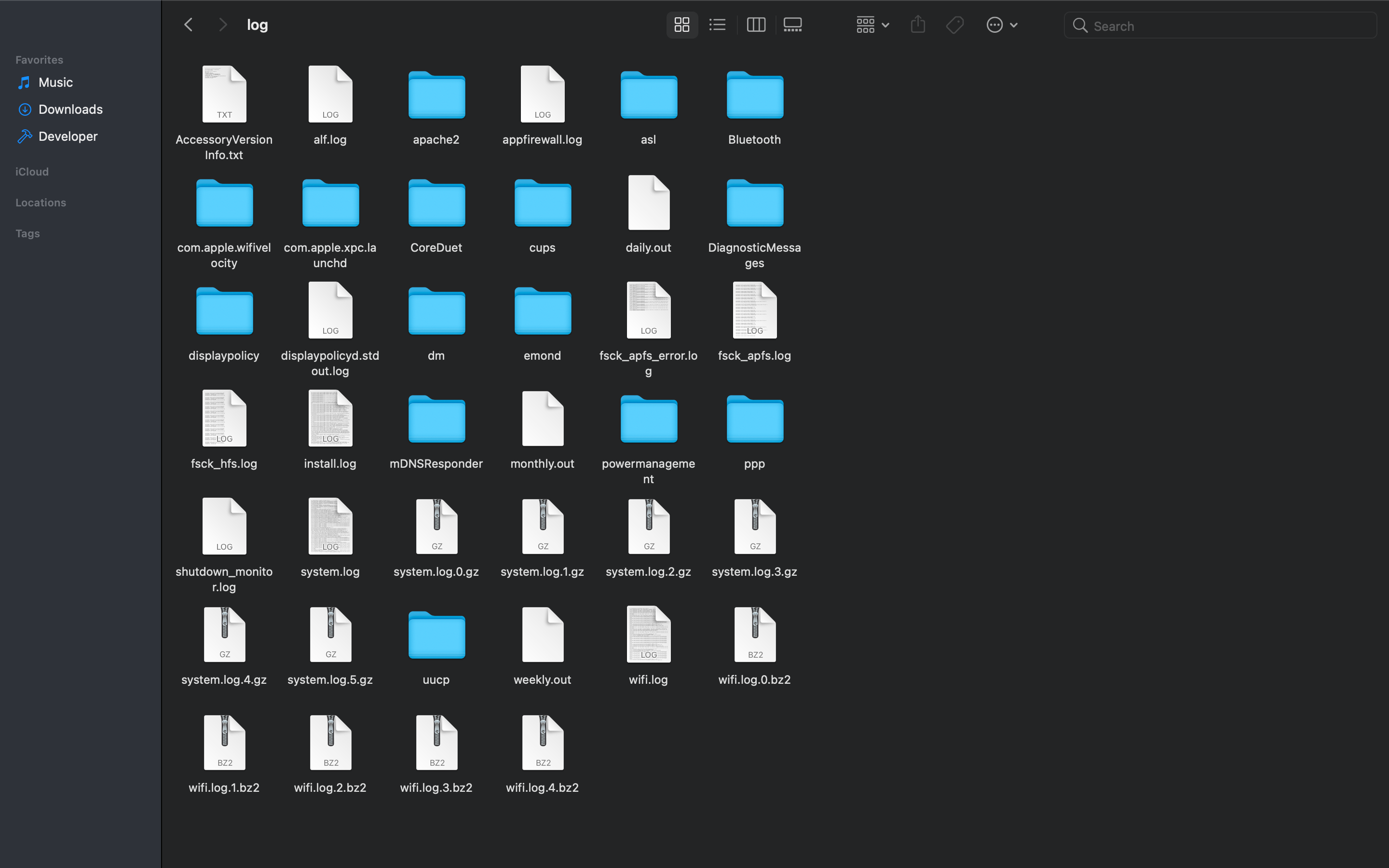
When you plug the sd card back into the mac, navigate to /var/log/syslog
then open it with a text editor
molten glen
steady rose
<@!816340200443740181> go back to just the ribbon cable and make sure you can re...
I was just doing that rn, another question: could I purchase wires for the FSR? so I dont have to plug it into the breadboard, its not long.
fast tapir
There will be lots and lots of info in there, but looking for ip-addresses will point you to the network stuff
bright meteor

 molten glen
 steady rose
^^ yah. that. are you looking for more info on what that is?
 molten glen
steady rose
^^ yah. that. are you looking for more info on what that is?
molten glen
steady rose
^^ yah. that. are you looking for more info on what that is?
yes
https://learn.adafruit.com/force-sensitive-resistor-fsr/connecting-to-an-fsr found it on this page but no link to the shop

i already have these but the FSR doesnt fit
its hard to lay the FSR flat when its very short
steady rose
hmm. those are essentially the same as guide. the FSR pin won't go into a female end connector?
molten glen
im going to try once more
steady rose
it's a hack. those aren't the exact same style connector.
so you may need to push firmly, etc.
fast tapir
bright meteor
it's just the regular one
This looks like your apple syslog, not the pi
ruby night
@molten glen this may be of interest https://forums.adafruit.com/viewtopic.php?f=8&t=175275&hilit=FSR
steady rose
might need to mount the pi's other partition from the SD card
molten glen
steady rose
so you may need to push firmly, etc.
ive torn one open and it wont reach
steady rose
the boot one is FAT, so mac is probably auto mounting it
@ruby night nice. thanks. that's good info.
molten glen
ruby night
<@!816340200443740181> this may be of interest <https://forums.adafruit.com/view...
what is the name of this?
like a generic name
ruby night
molten glen
Looks to be what I need, time to buy one.
guessing i can use the leads from before after putting the FSR into this connector
ohno shipping to UK is very expensive 😟
steady rose
try farnell/newark maybe?
molten glen
dont think they have it and shipping is still very expensive 😔
rs-online has it but need to buy a minimum of 10 and at that point its the same price as shipping from NA
mystic thistle
"tca9548a" I have installed the adafruit_tca9548a library via pip3 but the code fails because it says that the module is not found. I also tried the Sparkfun version of this driver and it will not import also. I am trying to connect to the SparkFun qwiic Mux (Adafruit - P4704)
Help??
steady rose
what was your exact pip install command?
mystic thistle
sudo pip3 install sparkfun-qwiic-tca9548a and sudo pip3 install adafruit_tca9548a
both said requirement compete (or something like that) @steady rose
mystic thistle
I will try that
@steady rose this is what I get:
Looking in indexes: https://pypi.org/simple, https://www.piwheels.org/simple
Requirement already satisfied: adafruit-circuitpython-tca9548a in /usr/local/lib/python3.7/dist-packages (0.4.0)
Requirement already satisfied: Adafruit-Blinka in /usr/local/lib/python3.7/dist-packages (from adafruit-circuitpython-tca9548a) (6.4.2)
Requirement already satisfied: Adafruit-PlatformDetect>=3.1.0 in /usr/local/lib/python3.7/dist-packages (from Adafruit-Blinka->adafruit-circuitpython-tca9548a) (3.4.1)
Requirement already satisfied: RPi.GPIO in /usr/lib/python3/dist-packages (from Adafruit-Blinka->adafruit-circuitpython-tca9548a) (0.7.0)
Requirement already satisfied: sysv-ipc>=1.1.0 in /usr/local/lib/python3.7/dist-packages (from Adafruit-Blinka->adafruit-circuitpython-tca9548a) (1.1.0)
Requirement already satisfied: pyftdi>=0.40.0 in /usr/local/lib/python3.7/dist-packages (from Adafruit-Blinka->adafruit-circuitpython-tca9548a) (0.52.9)
Requirement already satisfied: Adafruit-PureIO>=1.1.7 in /usr/local/lib/python3.7/dist-packages (from Adafruit-Blinka->adafruit-circuitpython-tca9548a) (1.1.8)
Requirement already satisfied: rpi-ws281x>=4.0.0 in /usr/local/lib/python3.7/dist-packages (from Adafruit-Blinka->adafruit-circuitpython-tca9548a) (4.2.6)
Requirement already satisfied: pyusb>=1.0.0 in /usr/local/lib/python3.7/dist-packages (from pyftdi>=0.40.0->Adafruit-Blinka->adafruit-circuitpython-tca9548a) (1.1.1)
Requirement already satisfied: pyserial>=3.0 in /usr/local/lib/python3.7/dist-packages (from pyftdi>=0.40.0->Adafruit-Blinka->adafruit-circuitpython-tca9548a) (3.5)
steady rose
how are you running your code?
mystic thistle
In Visual Code Debug and Lint. I get this message
Exception has occurred: ModuleNotFoundError
No module named 'adafruit_tca9548a'
File "/home/pi/Power/Display/battgui.py", line 8, in <module>
import adafruit_tca9548a
steady rose
it may be setup or configured for a different python version
mystic thistle
Current version of Python is 3.9.0
steady rose
not sure. i've never run python that way. but seems like a configuration thing with visual code.
mystic thistle
I will get that when running from command line also python3 battdui.py
steady rose
same thing from REPL?
mystic thistle
not used REPL. Do not know it
faint sparrow
faint sparrow
nvm got this to work, only issue I'm having now is its printing the barcode twic...
Anyone? 
steady rose
/usr/local/lib/python3.7/dist-packages
it's installing in a 3.7 location
what do you get from this?
python3 --version
Python 3.7.3
steady rose
just to be sure - this is on a Pi?
mystic thistle
pi3 but will run on PI0
steady rose
ok. one sec. let me boot one up and i'll run you through the REPL thing...
steady rose
REPL is just interactive python
so, try this:
pi@raspberrypi:~ $ python3
Python 3.7.3 (default, Jan 22 2021, 20:04:44)
[GCC 8.3.0] on linux
Type "help", "copyright", "credits" or "license" for more information.
>>> import adafruit_tca9548a
>>>
the >>> is the prompt
steady rose
seems like it
mystic thistle
That make sense, the VS Code interpreter was pointing to 3.9. I change that back to 3.7 and the error went away
thanks for your help @steady rose 😅
bright meteor
fast tapir
This looks like your apple syslog, not the pi
then which one
fast tapir
The sd card on the pi! This should be somewhere on your finder system
mystic thistle
Does the adafruit_tca9548a lib work with the SparkFun Qwicc Mux Breakout 8 Channel(Adafruit P4704)?
I am connecting multiple LC709203 but I do not see how to address them
with the qwicc_tca9548a lib
mystic thistle
I actually found the information I needed. Please disregard
bright meteor
fast tapir
The sd card on the pi! This should be somewhere on your finder system
can't find it
sorry
let me try again
molten glen

@steady rose why doesnt this work lol

remember that part from yesterday I tried to create my own lmfao
I might be onto something...
its very cursed
novel bay
Would really be grateful if someone could tell me whether a button shim can be combined with an eink display and attached to a RPi without soldering
 ashen parcel
novel bay
Would really be grateful if someone could tell me whether a button shim can be c...
ashen parcel
novel bay
Would really be grateful if someone could tell me whether a button shim can be c...
You could explore some of the options mentioned here.. https://electronics.stackexchange.com/questions/48814/what-is-solderless-post

Electrical Engineering Stack Exchange
I've seen metal "sticks" with a special end that let them fit snugly into a through-hole for when you want a contact but don't want to solder a wire into the hole. What are they called and where ca...
novel bay
Hey @ashen parcel this is exactly what I'll be using, sorderless headers from pimorini
The issue is I'm not sure whether I can add one female header with a shim as well as a pHAT
steady rose
@molten glen not sure i fully understand what you're trying there. also, no need to mention just me. lots of helpful people here. can just ask in the open and see who can help.
 copper kelp
is there a paper somewhere about the pi's GPU's?
copper kelp
nvm found it
ashen parcel
anyone here able to get MLX90614 working on Pi Pico?
 fleet summit
my raspberry pi will do internet a bit but then stop
like it says connected and it works on other devices
ashen parcel
fleet summit
like it says connected and it works on other devices
probably goes on sleep?
 wraith grove
any bridges?
faint sparrow
yea im thinking so
gonna fix it later i assume it isnt broken i just need to fix the solder right
 pliant fulcrum
My code doesnt work, it says there isnt a comment called "text" what should i do?

 hidden patio
faint sparrow
hidden patio
faint sparrow
oh no, thats pretty bad.... im assuming you dont use flux
you need to use it, its very important
finite bay
You can solder pins like that just fine without flux.
But IIRC they didn't have the proper soldering iron.
fierce spire
I´m currently accessing my rpi zero via vnc. Is there any way to start my tkinter gui program without booting the desktop to encrease performance?
wraith grove
X11 forwarding via SSH?
steady rose
@wraith grove -X
ashen parcel
fierce spire
I´m currently accessing my rpi zero via vnc. Is there any way to start my tkinte...
install the Lite version of the RPi OS. SSH to it while enabling X11. for ex: ~/ssh -X pi@123.456.7.89
steady rose
looks like device number is 0
molten glen
whoops i missed a line card 0: Headphones [bcm2835 Headphones], device 0: bcm2835 Headphones [bcm2835 Headphones], a bit confused but i realize that card and device number can be the same.
 jade pagoda
Eek that soldering
Maybe you should practice a bit with regular kits
I have a SP25 which can do 0603 with some extended practice and cheap irons can handle 2.54 very well
molten glen
Not sure if this is the correct channel, I have a Adafruit Voice Bonnet and the microphones are extremely good apart from the constant electronic whine noise, how do I stop that?
from the review page on pimoroni 😟
 umbral sable
molten glen
Not sure if this is the correct channel, I have a Adafruit Voice Bonnet and the ...
umbral sable
molten glen
Not sure if this is the correct channel, I have a Adafruit Voice Bonnet and the ...
Please avoid excessive cross-posting. The question is probably best for #help-with-audio
 dapper meteor
Hi , what is the wifi range of raspberry Pi 4?
 uncut lagoon
the important questiona are:
- where is the pi?
- how far away you need it to be?
- what materials are used for the building, if it is indoors?
and other things related to that
dapper meteor
@uncut lagoon the pi will be behind the concrete wall and I want it to connect with another device outside of the wall(open area )approx 100 m away.
(And mainly I want to know pi Wi-Fi coverage area approx)
Thanks in advance
uncut lagoon
i dont think it will work
you can try with an external antenna for the pi zero, but im not sure if the pi 4 has one
it seems the pi 4 doesnt have an external antenna, but you can get some cheapo dongle with one
wait
i was wrong
the external antenna on the pi zero seems to be an hack as well
an alternative could be an old router, which sometimes may be found for free
and you can set some routers as access points, and use it to make a network for the pi, with extra ports
or even an old access point
 jagged panther
how do i setup CCTV without motioneyeos, id like to use rasbian only\
think i found some info had to do "CCTV raspberry pi -motioneyeos" i learned how to exclude stuff in a search just now 🤪
 hard marsh
Hi there... looking for some help on Blinka Bridge. After receiving some number of messages, I get error below. I tried to add gc in the main loop, but no joy. The code running it is basically the demo code, but set to run while TRUE, so it just loops through the after the SCANNING print statement. ```Traceback (most recent call last):
File "ble_broadcastnet_blinka_bridge.py", line 119, in <module>
adafruit_ble_broadcastnet.AdafruitSensorMeasurement, interval=0.5
File "/home/pi/.local/lib/python3.7/site-packages/adafruit_ble/init.py", line 258, in start_scan
active=active,
File "/home/pi/.local/lib/python3.7/site-packages/_bleio/common.py", line 236, in start_scan
active=active,
File "/home/pi/.local/lib/python3.7/site-packages/_bleio/common.py", line 317, in _start_scan_hcitool
stderr=subprocess.DEVNULL,
File "/usr/lib/python3.7/subprocess.py", line 775, in init
restore_signals, start_new_session)
File "/usr/lib/python3.7/subprocess.py", line 1412, in _execute_child
errpipe_read, errpipe_write = os.pipe()
OSError: [Errno 24] Too many open files
you may have included some creation stuff in the loop that was only meant to run once
what line did you add the while True: to?
hard marsh
steady rose
you may have included some creation stuff in the loop that was only meant to run...
Yes, that is exactly the one I am using. As shown below, just after it starts scanning I added the line to make it loop and indented the rest. On the GIT page, line 114. ```print("scanning")
print()
sequence_numbers = {}
while True:
#gc.collect(generation=2)
# By providing Advertisement as well we include everything, not just specif$
for measurement in ble.start_scan(
adafruit_ble_broadcastnet.AdafruitSensorMeasurement, interval=0.5):
reversed_address = [measurement.address.address_bytes[i] for i in range$
sensor_address = "{:02x}{:02x}{:02x}{:02x}{:02x}{:02x}".format(*reverse$
print("Got a measurement")
if sensor_address not in sequence_numbers:
And then I can use a tkinter-Gui python script? Thank you I´ll try it
 unreal stirrup
today I find myself right back at the basics. My button switches are occasionally triggering without me pushing them. They are wired from the raspberry pi pin to the button and then to ground. In the python code I am using the GPIO library with the pull_up.
steady rose
still seems like a pull issue maybe?
unreal stirrup
so should I try removing the pull_up from the code and adding an external pull_up circuit?
steady rose
what GPIO library are you using?
unreal stirrup
import RPi.GPIO as GPIO
steady rose
can you share, or link, full code?
unreal stirrup
my full code is a crazy mess of things. I am over a year into a project (which was probably a little bit more than I have the expertise to complete). I will try to pull the code out for the button to share here
steady rose
yah, make just a simple button read program to help sanity check the behavior
should be like 10 lines of code
which pin is your button wired to?
https://pinout.xyz/#
unreal stirrup
GPIO.setup(sbutton,GPIO.IN, pull_up_down=GPIO.PUD_UP)
GPIO.add_event_detect(sbutton, GPIO.FALLING, callback=sbutton_interrupt, bouncetime=400)
I assume there is someway to put code into the chat better than this. I am looking for the pin number now. I have many units and not all are using the same pin. the basic button code worked when I started the project and only had the button
unreal stirrup
BCM pin 12
but my problems are so infrequent that I don't know that I will see a problem with the basic code
steady rose
import RPi.GPIO as GPIO

channel = 12

GPIO.setmode(GPIO.BCM)
GPIO.setup(channel, GPIO.IN, pull_up_down=GPIO.PUD_UP)

while True:
    if GPIO.input(channel):
        # button not pressed
        # print('Input was HIGH')
        pass
    else:
        # button pressed
        print('Input was LOW')
run that and let it sit. you should never see any output.
unreal stirrup
ok I will go set it up for today and see what happens.
steady rose
run it with the HIGH print uncomment just to verify basic functionality
but then comment it out for testing
unreal stirrup
good advice 🙂
steady rose
the output will be spammy, but its simple code for basic testing
unreal stirrup
I understand your "output will be spammy" comment now. There is no debounce on the button. I have it setup and running now. I am not fully understanding where this troubleshooting is leading but i am excited to find out. What conclusions are you going to draw if there are no false button presses (without the other electronics running I am guessing that I have a good chance of seeing no false pushes)? And if there are false button presses is this when an external pull-up might help me?
steady rose
@unreal stirrup sry, went AFK for a bit. "spammy" as it will print something whether button is pressed or not (if you uncomment lines). so for actual testing, comment out the print statement for when button is NOT pressed. that way you should be able to let it sit there forever and see nothing.
final solstice
Question: I'm looking to use PyGame to display an interface on my pi with this H5MI display: https://www.adafruit.com/product/1678
If possible, I'd like to use a headless setup (without desktop).
Will this method pointing PyGame to the framebuffer still work? https://learn.adafruit.com/pi-video-output-using-pygame/pointing-pygame-to-the-framebuffer
I have Raspberry Pi 3 Model B with latest Raspberry Pi OS (buster) installed without Desktop and 8gb of RAM.

Yes, this is a cute little 5" TFT display with WVGA 800x480 resolution (NOT TOUCHSCREEN). We tried to get the smallest display that would be good for embedded computing usage and at a ...
 hard marsh
steady rose
you may have included some creation stuff in the loop that was only meant to run...
hard marsh
steady rose
you may have included some creation stuff in the loop that was only meant to run...
Did you happen to see any red flags in my changes?
steady rose
@hard marsh don't know the solution, but pretty sure it's related to what is happening under the hood. the start_scan call does some subprocess stuff that may leave stuff open with each call.
hard marsh
I am learning debugging with Code, so will try to follow it down that hole. Thanks!
steady rose
@humble marsh any ideas ^^ BLE related (original issue in scroll back), calling start_scan in loop eventually leads to OSError: [Errno 24] Too many open files
 humble marsh
@hard marsh try adding ble.stop_scan() at the bottom of the loop, on the same indent level as the for ... start_scan()
there may be some other error, but this ameliorate the problem.
hard marsh
humble marsh
<@448616830622367764> try adding `ble.stop_scan()` at the bottom of the loop, on...
👍
humble marsh
it should do the stop_scan() automatically, which should terminate the hcitool process, so I'm a little :head_scratch:
hard marsh
humble marsh
it should do the `stop_scan()` automatically, which should terminate the hcitool...
Well, running it now. Will let you know in a few minutes
hard marsh
humble marsh
it should do the `stop_scan()` automatically, which should terminate the hcitool...
Sad Trombone sound. ```Traceback (most recent call last):
File "ble_broadcastnet_blinka_bridge.py", line 119, in <module>
adafruit_ble_broadcastnet.AdafruitSensorMeasurement, interval=0.5
File "/home/pi/.local/lib/python3.7/site-packages/adafruit_ble/init.py", line 258, in start_scan
active=active,
File "/home/pi/.local/lib/python3.7/site-packages/_bleio/common.py", line 236, in start_scan
active=active,
File "/home/pi/.local/lib/python3.7/site-packages/_bleio/common.py", line 317, in _start_scan_hcitool
stderr=subprocess.DEVNULL,
File "/usr/lib/python3.7/subprocess.py", line 775, in init
restore_signals, start_new_session)
File "/usr/lib/python3.7/subprocess.py", line 1412, in _execute_child
errpipe_read, errpipe_write = os.pipe()
OSError: [Errno 24] Too many open files
could you upload your whole program? Use the + button on the left
hard marsh
hard marsh
humble marsh
could you upload your whole program? Use the + button on the left
Thanks for the hint on loading the file!
humble marsh
hard marsh
Thanks for the hint on loading the file!
I think I see the problem. I'll give you a file to test in a few minutes
hard marsh
humble marsh
I think I see the problem. I'll give you a file to test in a few minutes
Thank you Sir.
humble marsh
hard marsh
Thank you Sir.
Please try this: unzip this file someplace, and then do pip3 install Adafruit_Blinka_Bleio. That will overwrite your current installation.
final solstice
Question re-up (let me know if this too frequent) :
I'm looking to use PyGame to display an interface on my pi with this H5MI display: https://www.adafruit.com/product/1678
If possible, I'd like to use a headless setup (without desktop).
Will this method pointing PyGame to the framebuffer still work? https://learn.adafruit.com/pi-video-output-using-pygame/pointing-pygame-to-the-framebuffer
I have Raspberry Pi 3 Model B with latest Raspberry Pi OS (buster) installed without Desktop and 8gb of RAM.
Yes, this is a cute little 5" TFT display with WVGA 800x480 resolution (NOT TOUCHSCREEN). We tried to get the smallest display that would be good for embedded computing usage and at a ...
hard marsh
humble marsh
Please try this: unzip this file someplace, and then do `pip3 install Adafruit_B...
From the install
Sorry for the mess above... it does not look like anything installed, but running it now.
humble marsh
Do this: cd Adafruit_Blinka_bleio; pip3 install .
it did not reinstall, so you are running the old version
hard marsh
Ah, did it in the examples folder
humble marsh
it tries hard to find Adafruit_Blinka_bleio in the name of stuff it downloaded from pypi.org, so we have to circumvent that
I actually did a pip3 install . locally because I was in the repo folder
I guessed wrong that it would use the unzipped folder
hard marsh
humble marsh
I guessed wrong that it would use the unzipped folder
Building wheels for collected packages: adafruit-circuitpython-ble-broadcastnet
  Building wheel for adafruit-circuitpython-ble-broadcastnet (setup.py) ... done
  Created wheel for adafruit-circuitpython-ble-broadcastnet: filename=adafruit_circuitpython_ble_broadcastnet-0.10.6.dev0+gac76109.d20210422-py3-none-any.whl size=6307 sha256=d30f77e562ccc4cac7ee898f428c4ab9ecdfb1efff662cd2a2d06dc5c328fafc
  Stored in directory: /tmp/pip-ephem-wheel-cache-wcn9lxx9/wheels/a5/db/38/77ca41cf35af52b86c3a4e8e752406db5e2a45c06bf9ad77da
Successfully built adafruit-circuitpython-ble-broadcastnet
Installing collected packages: adafruit-circuitpython-ble-broadcastnet
  Attempting uninstall: adafruit-circuitpython-ble-broadcastnet
    Found existing installation: adafruit-circuitpython-ble-broadcastnet 0.10.5
    Uninstalling adafruit-circuitpython-ble-broadcastnet-0.10.5:
      Successfully uninstalled adafruit-circuitpython-ble-broadcastnet-0.10.5
Successfully installed adafruit-circuitpython-ble-broadcastnet-0.10.6.dev0+gac76109.d20210422```it looks like you reinstalled broadcastnet. Unpack the zip somehwere else, like in ~/temp, and then cd Adafruit_Blinka_bleio; pip3 install .
are you using a modified copy of broadcastnet?
hard marsh
humble marsh
it looks like you reinstalled broadcastnet. Unpack the zip somehwere else, like ...
Slightly modified, added a few print statements.
humble marsh
if not do pip3 install adafruit-circuitpython-ble-broadcastnet==0.10.5
it is all confused because of where you unpacked the zip. Remove the version from the examples folder and unpack it somewhere else for safety
hard marsh
I will do that, take it back to basics.
humble marsh
then do pip3 list |grep ble so you can check what versions you have
hard marsh
adafruit-blinka-bleio                   2.2.1.dev0+g03b094d.d20210422
adafruit-circuitpython-ble              7.3.4
adafruit-circuitpython-ble-adafruit     1.2.4
adafruit-circuitpython-ble-broadcastnet 0.10.6.dev0+gac76109.d20210422
bleak                                   0.11.0
blessings                               1.6
Should I do the install .10.5?
humble marsh
no, your print statements should be fine. That looks good: the blinka-bleio is my test version
go ahead and try it; I tested on a pulse oximeter, but not in broadcastnet
hard marsh
Running now! I really don't need to see my own pulse between trying to fix this and a Mountain Dew
Hmmm, now I see no data at all.
It sends every 30 seconds
humble marsh
bleh
hard marsh
Should I try the simpletest file you included in examples?
humble marsh
you could, but it will probably work; there's something about the way you are using it that's different
hard marsh
Actually there are just headers in the file. No running code
The original GIT code goes through to SCANNING, then immediately to SCAN DONE. When it was working before, it waited until it received the first data, then finished.
humble marsh
i see a problem, hold on
@hard marsh this is going to take some further more intense debugging; I fixed one problem that should make it work but the Linux state of BLE gets messed up.
I can't do this right now but will work on it later
if you don't use hcitool/hcidump, then do you not get all the data?
hard marsh
All right... any easy way of returning to the semi-functional state?
humble marsh
sure just pip3 install adafruit-blinka-bleio==2.2.0. That will install the latest release without patches
hard marsh
I will check with hci
humble marsh
Put this on your PATH somewhere before /usr/bin/hcitool, and rename it hcitool instead of hcitool.off. You can rename it back and forth to disable/enable using hcitool. This fake version returns with an error and so disables the use of hcitool.
that is what I use for testing with/without the real hcitool
and of course chmod +x it
hard marsh
ok
hard marsh
@humble marsh I actually use a tool called bluetoothctl. Not sure what I am supposed to do with hcitool.
humble marsh
hcitool and hcidump are used together by adafruit-blinka-bleio to do scanning
hard marsh
Ah, thanks.
humble marsh
you don't see them being used. blinka-bleio tries hcitool first to see if it's working. The "hcitool.off" script above pretends to be a non-working hcitool, it returns a non-zero exit code. If that happens, blinka-bleio doesn't use hcitool/hcidump to do scanning. did you read this? https://github.com/adafruit/Adafruit_Blinka_bleio#support-for-duplicate-advertisement-scanning-on-linux
hard marsh
No, reading it now.
Not wishing to be obtuse, but not sure if I am doing that... ```# SPDX-FileCopyrightText: 2021 ladyada for Adafruit Industries
SPDX-License-Identifier: MIT
"""This is a basic sensor node that uses the internal temperature sensor and reports it every 10
seconds."""
import time
import microcontroller
import adafruit_ble_broadcastnet
print("This is BroadcastNet sensor:", adafruit_ble_broadcastnet.device_address)
while True:
measurement = adafruit_ble_broadcastnet.AdafruitSensorMeasurement()
measurement.temperature = (
microcontroller.cpu.temperature # pylint: disable=no-member
)
print(measurement)
adafruit_ble_broadcastnet.broadcast(measurement)
time.sleep(10)```
I thought this send the advertisement and then the data upon reply.
humble marsh
broadcastnet is connectionless, it just sends the data to anyone who is listening
hard marsh
Ah, got it.
unreal stirrup
@steady rose had me run a simple button test script to help me solve my occasional false triggering problem. Now I have a good baseline since in 24 hours I didn't get any false triggers. This of course is with my pi pretty much in sleep mode not when running its lights, selector or display. I was wondering if an external pull-up resistor might help. If so, does 10k for the resistor sound good and do I turn the internal pull_up off?
hard marsh
humble marsh
Put this on your PATH somewhere before `/usr/bin/hcitool`, and rename it `hcitoo...
OK, climbing the learning curve here. There is MUCH conflicting info about putting stuff into PATH. I don't have .bash_profile, .bash_login, or .bash_aliases, there isn't much other than prog completion and bash aliases in .bash_rc, and only the below in .profile. I cannot figure out quite how to "Put this on your PATH somewhere before /usr/bin/hcitool" Can you point me to a better answer (or just give me the spoiler command line)? ```# if running bash
if [ -n "$BASH_VERSION" ]; then
# include .bashrc if it exists
if [ -f "$HOME/.bashrc" ]; then
. "$HOME/.bashrc"
fi
fi
set PATH so it includes user's private bin if it exists
if [ -d "$HOME/bin" ] ; then
PATH="$HOME/bin:$PATH"
fi
set PATH so it includes user's private bin if it exists
if [ -d "$HOME/.local/bin" ] ; then
PATH="$HOME/.local/bin:$PATH"
fi
that .profile looks good: Do this:
cd ~
mkdir bin
mv hcitool.off bin/hcitool # will turn it on because it will be in path, before the `/usr/bin/hcitool`
now you have a ~/bin directly you can put your own executables into. don't forget to chmod +x bin/hcitool if you haven't already added execute permissions
hard marsh
humble marsh
that .profile looks good: Do this:
```sh
cd ~
mkdir bin
mv hcitool.off bin/hcito...
Still trying to understand exactly what I just did, but I do understand the result... IT WORKS! Been running fine, now adding more code to break it again! Thank you!
humble marsh
make sure you are getting multiple readings from the sensor. The problem with not using hcitool/hcidump is that the Linux kernel does duplicate advertisement filtering. so you may get only the first reading
i think it filters on the sender, not the rest of the data in the advertisement, but I'm not sure off the bat
hard marsh
Done logging measurement to IO. Took 0.4253011050168425 seconds

bridge-dca63203bff5-sensor-ee2f92475c90 [{'key': 'missed-message-count', 'value': 0}, {'key': 'temperature-0', 'value': 29.5}]
Done logging measurement to IO. Took 0.4855495730880648 seconds

bridge-dca63203bff5-sensor-ee2f92475c90 [{'key': 'missed-message-count', 'value': 0}, {'key': 'temperature-0', 'value': 29.5}]
Done logging measurement to IO. Took 0.44616022799164057 seconds

bridge-dca63203bff5-sensor-ee2f92475c90 [{'key': 'missed-message-count', 'value': 2}, {'key': 'temperature-0', 'value': 29.75}]
Done logging measurement to IO. Took 0.4710682409349829 seconds

bridge-dca63203bff5-sensor-ee2f92475c90 [{'key': 'missed-message-count', 'value': 0}, {'key': 'temperature-0', 'value': 29.5}]
Done logging measurement to IO. Took 0.45582288410514593 seconds
put your finger on the sensor 🙂
hard marsh
I only have one sender running right now
Done logging measurement to IO. Took 0.43507031886838377 seconds

bridge-dca63203bff5-sensor-ee2f92475c90 [{'key': 'missed-message-count', 'value': 2}, {'key': 'temperature-0', 'value': 33.5}]
Done logging measurement to IO. Took 0.45801533991470933 seconds

bridge-dca63203bff5-sensor-ee2f92475c90 [{'key': 'missed-message-count', 'value': 1}, {'key': 'temperature-0', 'value': 34.5}]
Done logging measurement to IO. Took 0.4541545968968421 seconds
If you are working on a more permanent fix, can please PM me when I should try it without disabling hcitool?
Much easier to deploy that way.
 timber shale

running sudo ./demo -D0 --led-rows=64 --led-cols=64 --led-chain=4 --led-slowdown-gpio=2 --led-multiplexing=0
why? :S
in the terminal i can see that it thinks it's a "256x64".... and not "256x256"
timber shale
aaaaaaaaaaaaaaaaaaaaaanyyy one?
umbral sable
Sounds like the rows/cols/chain parameters aren't quite working like you expect them to... it's treating them like "this is a chain of 4 64x64 panels", which probably isn't what you have.
timber shale
i dont know what is happening :S
timber shale
@umbral sable https://streamable.com/u1nccq so i got this far... but still there are these lines :S

https://learn.adafruit.com/raspberry-pi-led-matrix-display/software
This tutorial does not work with the Pi 4 - no ETA on when it may be fixed!

Adafruit Learning System
Show the Pi's video output on a large RGB LED matrix display!
😦
timber shale
i updated that project with the lastest rpi-rgb-led-matrix library but something is a miss
 stoic finch
Solved my gpio pass through problem with a slightly different cobbler I think

 timber shale
anyone who have used this -> https://github.com/hzeller/rpi-rgb-led-matrix/blob/master/examples-api-use/README.md befor?

GitHub
Controlling up to three chains of 64x64, 32x32, 16x32 or similar RGB LED displays using Raspberry Pi GPIO - hzeller/rpi-rgb-led-matrix
that can help me
when i try to compile that demo script in there i get
pi@raspberrypi:~/rpi-rgb-led-matrix/Mythical $ sudo gcc main.cpp
/usr/bin/ld: /tmp/ccoeHQYi.o: in function `main':
main.cpp:(.text+0x1c): undefined reference to `rgb_matrix::RGBMatrix::Options::Options()'
/usr/bin/ld: main.cpp:(.text+0x58): undefined reference to `rgb_matrix::RuntimeOptions::RuntimeOptions()'
/usr/bin/ld: main.cpp:(.text+0x80): undefined reference to `rgb_matrix::RGBMatrix::CreateFromFlags(int*, char***, rgb_matrix::RGBMatrix::Options*, rgb_matrix::RuntimeOptions*, bool)'
/usr/bin/ld: main.cpp:(.text+0xac): undefined reference to `rgb_matrix::PrintMatrixFlags(_IO_FILE*, rgb_matrix::RGBMatrix::Options const&, rgb_matrix::RuntimeOptions const&)'
collect2: error: ld returned 1 exit status
It looks like it comes with makefiles, so you should probably use those instead of calling gcc directly... there are probably some additional libraries or flags that it needs.
 normal vapor
so i have raspbian lite, and i need to install raylib onto the pi. i don't have a usb stick, or an sd card
what do i do
 trail belfry
GIT clone the source
then follow this guide

GitHub
A simple and easy-to-use library to enjoy videogames programming - raysan5/raylib
That would be my guess without any knowledge or experience with raylib
normal vapor
alrighty thanks
i'm currently cloning it
however i wonder
there are like 15 releases
so how would i clone a certain release
can i even do that?
actually no i need a specific asset
 coral valve
Hello everybody. I need help with Raspberry Pi: I need to create an access point that will share TOR traffic. A similar project already exists on Adafruit, but it did not work for me. The access point works, but when I configure routing through the TOR, it stops sharing the internet, but I can still see it in the list of networks. How to make a TOR access point correctly? I use RPi model B+ with TL-WN725N dongle with installed drivers.
 hollow mica
good night I would like you to help me to show images in 32 x 32 and 64 x 64 thanks
pixel_pin = board.D18
pixel_width = 32
pixel_height = 32
https://learn.adafruit.com/easy-neopixel-graphics-with-the-circuitpython-pixel-framebuf-library/image-drawing-with-python
coral valve
hey guys
coral valve
coral valve
Hello everybody. I need help with Raspberry Pi: I need to create an access point...
can some1 help with it?
 velvet frigate
@coral valve try this
https://www.torbox.ch/
the have an image file and install script

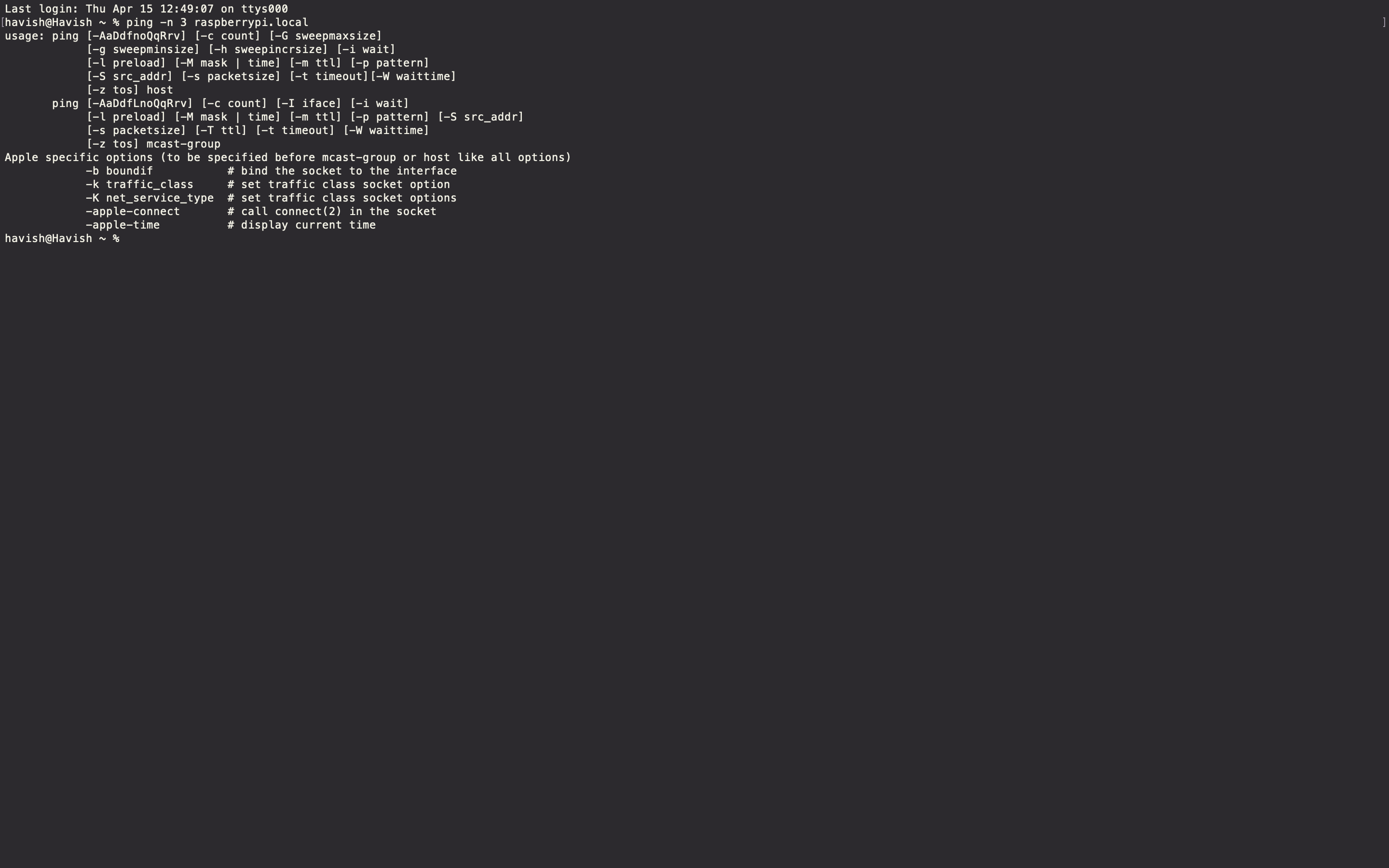
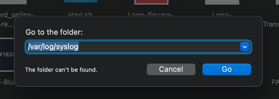
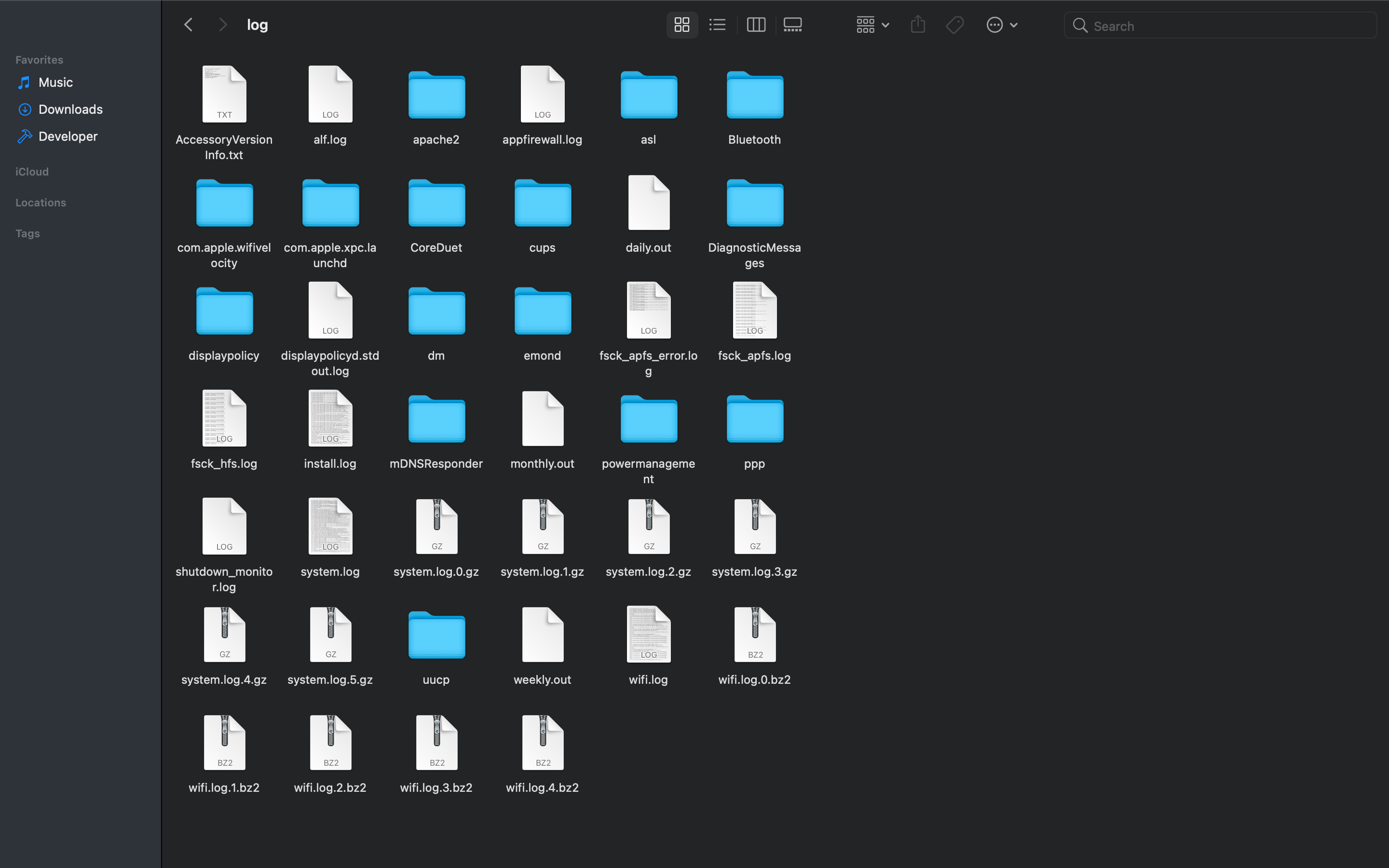




 coral valve
I've tried this one, but how can I install wifi drivers on it?
My wifi dongle don't work out of the box, so I need to install wifi drivers every time I run system
coral valve
I just found out that I cannot access sites related to TOR, even torproject.org. Could it be possible that TOR is prohibited in my country and I cant create an access point because of this?
uncut lagoon
it is possible, yes
try using hidemyass.com with the webpage proxy, to try and download the program, if you want
or you can try a vpn, like tunnelbear or nordvpn or similars
hollow mica
image-drawing-with-python
good night I would like you to help me to show images in 32 x 32 and 64 x 64 thanks
pixel_pin = board.D18
pixel_width = 32
pixel_height = 32
https://learn.adafruit.com/easy-neopixel-graphics-with-the-circuitpython-pixel-framebuf-library/image-drawing-with-python

Adafruit Learning System
Use the Pixel Framebuf library to easily add text, primitive graphics, and images to a grid of NeoPixels
coral valve
uncut lagoon
it is possible, yes
so it means that I cant make my TOR AP anyway?
uncut lagoon
the access to the tor page has nothing to do with the tor protocol
now, it is possible that your isp blocks all tor nodes, so
coral valve
ok... i dont understand why none of the TOR AP guides works
coral valve
So I raise my AP with hostapd and dhcp, and it works. Then when I install and configure TOR on my raspberry, i can connect to my AP, but i get "No internet connection"
uncut lagoon
can you use the tor browser on your pc?
coral valve
yes, it works
uncut lagoon
nuke it and try again?
uncut lagoon
also, make sure the ips are correct
coral valve
how? 😄
coral valve
no
uncut lagoon
if it worked, it would have been a miracle
coral valve
so how can i make it work?
TorBox doesn't work because of its new version of raspbian, and i cant install drivers
coral valve
uncut lagoon
i mean, did you even checked what ip your gateway has?
i'll do installation again manually, can u help me with checking it?
uncut lagoon
the website says which specific version to use and has all the links
use etcher to write the image to the sd card
coral valve
i know, but TorBox is based on the latest version of Raspbian and driver for my wifi-dongle doesnt work
coral valve
RPi Model B+
uncut lagoon
which one?
coral valve
Raspberry Pi 1 Model B+
uncut lagoon
and you want to access to it over wifi?
coral valve
i want to make it work as AP
to share internet
with wi-fi dongle
i access to it with SSH through Ethernet
 quaint schooner
whats the TOR box for? entering the deep sice of the network?
uncut lagoon
if you know the onion link
but also used to go around government censureship and allowing to access content from other countries
like, watching videos from bbc uk
and also as a layer to anonymize you, but using the tor browser is better for that
quaint schooner
uncut lagoon
but also used to go around government censureship and allowing to access content...
so its like a mini computer where i can search for the links of the deep, and censored content?
 random bison
Would a RPi4 CM have enough power to run two motioneye cameras at 1080p? Or should I I with 2x RPi?
uncut lagoon
quaint schooner
so its like a mini computer where i can search for the links of the deep, and ce...
it opens the gates for you to be able to do that, if you want
coral valve
uncut lagoon
let me guess: you bought the first dongle you saw?
i saw that my dongle supports Linux and bought it
it works with standard AP which i can make with hostapd
but doesn't work with TOR AP
uncut lagoon
weird stuff then
 rose gull
I have raspberry pi 4
Bought 16 gb mini sim can’t get the os onto it to work someone please help I am very upset I have very limited funds to waste on this !!!!
uncut lagoon
make sure the reader is working properly, that the card is properly connected
and if you use an sdcard adapter, make sure it isnt locked
quaint schooner
uncut lagoon
it opens the gates for you to be able to do that, if you want
thank you very mucho
rose gull
i know that data is being placed onto the mini sim. I went through a youtube guide 3 times something is being left out!!
rose gull
microsd hc 16gb
rose gull
Anybody else have ideas?
 mint pagoda
@rose gull what file system. Needs to be Fat 32.
rose gull
So with the micro as what do I do for fat 32 I downloaded software to format it is that additional or what?
hollow mica
image-drawing-with-python
good night I would like you to help me to show images in 32 x 32 and 64 x 64 thanks
pixel_pin = board.D18
pixel_width = 32
pixel_height = 32
https://learn.adafruit.com/easy-neopixel-graphics-with-the-circuitpython-pixel-framebuf-library/image-drawing-with-python
Adafruit Learning System
Use the Pixel Framebuf library to easily add text, primitive graphics, and images to a grid of NeoPixels
coral valve
can i make wifi router based on rpi with completely free vpn?
 sacred trellis
coral valve
can i make wifi router based on rpi with completely free vpn?
sacred trellis
coral valve
can i make wifi router based on rpi with completely free vpn?
You can make a WiFi router based on rpi. Speaking of VPN or Virtual Private Network, you can use PiVPN
It depends for what reason do you need a VPN
 tidal apex
Hi, is there a Jukebox Software besides Vollumio that allows for audio input via Bluetooth?
 pseudo chasm
Hey, I'm getting an issue where I'm getting a temporary failure in name resolution when i'm on my university network, does anyone have a fix for this?
this is the first time I ever received an error like this, all my ssh and remote connections into the pi are working fine, I have a feeling it has something to do with my university network
 molten steeple
HI! can someone please tell me how do I install the required files on my raspberry? Do I only move them to a specific location? If yes, where to? Thanks!
uncut lagoon
you need to create an image on the sdcard
its a lot easier if you just use the official raspberry pi imager
it does everything for you
if you want extra configurations, the latest version has a keyboard shortcut for it
im not sure which because it isnt intuitive
molten steeple
@uncut lagoon hi, my raspberry is already installed with raspbian os :D. What I meant is how do I install adafruit libraries with circuit python? what I meant there was that I see the files on github, and no installation file. Do I need to just download adafruit-circuitpython files to a specific folder or there's an installation process? Thank you!
uncut lagoon
you have to install blinka
just the standard pip3 install Adafruit-Blinka
(or with sudo)
ruby night
there is a full guide here https://learn.adafruit.com/circuitpython-on-raspberrypi-linux/installing-circuitpython-on-raspberry-pi
uncut lagoon
that's a lot different from what i found o.O
wait, that's 1 step next from what i read :x
ruby night
once Blinka is inatalled -- you install libraries with pip3 pip3 install adafruit-circuitpython-bme280 for example
You need to set up the dependencies -- now there is a script to do most of it for you.
pseudo chasm
My pi isn't connecting to the network anymore after i messed around in the interface files trying to connect to the eduroam network at my university, does anyone have a fix for this?
Only thing I can think of is completely wiping the sd card and resinstalling everything but I don't want to lose the programs i created in there already
ruby night
you can try restoring the originnal /etc/network/interfaces file -- here is what it on mine ```# interfaces(5) file used by ifup(8) and ifdown(8)
Please note that this file is written to be used with dhcpcd
For static IP, consult /etc/dhcpcd.conf and 'man dhcpcd.conf'
Include files from /etc/network/interfaces.d:
source-directory /etc/network/interfaces.d
or did you change some of the other files as well
 proven vigil
Hi
i have a question about some error!
So i was doing raspberry pi with security camera

Now let's get the python code running! On the Pi, make a folder on the desktop called mcselfie. It must be the exact name so that the code can run. Open a new tab in your Pi's web browser and go to this shortlink: adafru.it/selfiecode. Extract the .zip file and drag the .py file into the mcselfie folder on your desktop.
this shortlink
for selfiecode is not working. Where can I find this code? so I can put it on raspberry pi?
Thanks!
ruby night
hmm ...-it is a broken link,,, you can try posting a note in the "feedback" for the guide and also post a question to the support forum - maybe here https://forums.adafruit.com/viewforum.php?f=50
proven vigil
how to unlink from dropbox uploader. I put wrong key number
pseudo chasm
ruby night
you can try restoring the originnal /etc/network/interfaces file -- here is wha...
is there a way to change this from the SD card because I can't ssh back into my pi now
ruby night
You ‘might’ be able to mount the SD in another Linux computer and edit the file there. If you can get to it.
pseudo chasm
i mean, I only really have one code in there for a stepper motor application that was pretty basic, it'll probably save me time just starting the pi from scratch
steady rose
you can also edit /boot/wpa_supplicant.conf to try and reconfigure wifi and see if you can get back in
if you put the SD card in another PC, the /boot folder should show up
coral valve
Hi everyone! Is it possible to turn my Raspberry Pi into a TOR proxy server with worldwide access? For example, can I connect RPi to a router at home and use TOR proxy on it in any place in my country?
 hardy plaza
pseudo chasm
Only thing I can think of is completely wiping the sd card and resinstalling eve...
hardy plaza
pseudo chasm
Only thing I can think of is completely wiping the sd card and resinstalling eve...
If you know where the files you want are, I'd just connect the SD card to a desktop computer and copy the files you want from /home/pi as a backup, then re-image the SD card with a fresh copy of the OS. It's pretty difficult to fix a network problem if you a) don't know what the problem is, and b) don't know how to fix it.
pseudo chasm
hardy plaza
If you know where the files you want are, I'd just connect the SD card to a desk...
I'm pretty sure the problem is with the edits I made to the interfaces page under the network folder, I was following some guide online that had me sudo su and make some edits through the root user, where I then edited the file with the ssid information and deleted a network in there, now I can't get back into the pi at all
hardy plaza
pseudo chasm
I'm pretty sure the problem is with the edits I made to the interfaces page unde...
If you know what files you modified and have a second Pi SD card you could copy the originals from there. I generally make a backup copy of a system file before I edit it, like I make a copy of /etc/foo to /etc/foo_1. Then if I screw up I can just mv /etc/foo_1 /etc/foo
But it's easy to waste many hours trying to fix a broken OS, and when you don't have that much invested in the OS it's generally just easier to start over. Like I said, copy the files you've created onto a backup and start over. Life is too short.
coral valve
Hi everyone! Is it possible to turn my Raspberry Pi into a TOR proxy server with worldwide access? For example, can I connect RPi to a router at home and use TOR proxy on it in any place in my country?
hardy plaza
coral valve
Hi everyone! Is it possible to turn my Raspberry Pi into a TOR proxy server with...
The answer to your question is yes. The Raspberry Pi is simply a Linux computer, and TOR servers are Linux computers. It's beyond the scope of a chat channel to detail how you'd do that, but there's no inherent limitation in the Raspberry Pi Operating System that would prohibit you from setting it up as a TOR server. Comparing a Raspberry Pi 4 with its on-board network hardware with a dedicated 12 core 32GB Intel i9 Linux box running a fiber NIC on a fast network, but I'm sure you wouldn't expect that kind of performance. But the important thing to remember is that a Pi is simply a Linux computer.
hardy plaza
By worldwide access you mean being on the Internet. That's a function of working with your network provider to get yourself a static IP address, then configuring your local router to port forward the Pi. See: https://www.raspberrypi.org/documentation/remote-access/access-over-Internet/
Need to access a Raspberry Pi, but don’t have a monitor spare? This section provides basic instructions for setting up remote access.
But if you do this you should be aware that the moment your Pi is on the Internet it will come under attack. You'd have to security-harden it, especially if it's a TOR server.
 mellow condor
can i use a 2.2k resistor as a pull up for a switch on the rpis gpio? haven't really done much with gpio
hardy plaza
mellow condor
can i use a 2.2k resistor as a pull up for a switch on the rpis gpio? haven't re...
You can but it'd be pulling a lot more current than is necessary to do the job. I'd recommend a 10K.
mellow condor
hardy plaza
You can but it'd be pulling a lot more current than is necessary to do the job. ...
so would a 10k between the 3v3 pin and the switch, and then directly connecting the switch to a gpio pin?
hardy plaza
mellow condor
so would a 10k between the 3v3 pin and the switch, and then directly connecting ...
That depends on whether you want the default high or low.
mellow condor
doesn't really matter, I just need to check whether the switch is flipped or not
how about when the switch is open, the gpio reads low
hardy plaza
If you want default high you'd tie the GPIO pin to V+ via the 10K resistor, then have the switch connected (as well) to the GPIO pin, it connected to ground (V-). Then when the switch is closed it pulls the pin low.
If you want default low you do the opposite.
Basically a pull-up or pull-down resistor just takes an open pin (the pin when the switch is not turned on) and pulls it either to positive or negative. The switch then pulls it the other way.
mellow condor
so would a pull up resistor be more ideal than a pull down resistor?
hardy plaza
No, they're exactly the same thing. It only depends on whether you want your default when the switch is off to be high (+) or low (-).
There's no preference except for what you want the default to be when the switch isn't turned on.
mellow condor
ah i see thank you
 narrow wave
Are the castellated edges of the Pico plated?
 raw solar
Yup!
narrow wave
Ooh! Lovely!
raw solar
Indeed
 fickle spoke
I have hooked up two, 14x4 segment displays but cant get them to chain, it just copies the text displayed
what needs to happen so that the text appears on the rightmost segment and shifts left, leaving 8 total character spots?
I'm using a raspberry pi zero w by the way, let me know if I posted this in the wrong channel
fickle spoke
i got it to work
 fallow fox
Greetings, I'm using 2 VL53L0X sensors on my raspberry pi zero. When i try to run the multi example from this library (https://github.com/adafruit/Adafruit_CircuitPython_VL53L0X) I have a strange issue, One of my sensors seems to be capped at 400mm.
GitHub
CircuitPython module for interacting with the VL53L0X distance sensor. - adafruit/Adafruit_CircuitPython_VL53L0X

as my sensor a problem ?
raw solar
Might be faulty? I would try swapping 1 and 2 to see if it makes a difference -- if you see sensor 2 give that same result after swapping, I'd say it's that sensor
fallow fox
Yep, after further testing, my sensor seems faulty. But this is really strange that there is no problem before 360 mm
raw solar
strange... usually those are either working or totally dead in my experience
fallow fox
raw solar
strange... usually those are either working or totally dead in my experience
Yes, that's why i'm asking 🤷♂️ Well if think i will just try with an other
raw solar
faulty parts suck DX
fallow fox
raw solar
faulty parts suck DX
Yes clearly ! And I'm working on a project that someone has already beggan ... So it's strange that it stopped working with me
raw solar
weird
umbral sable
fallow fox
Yep, after further testing, my sensor seems faulty. But this is really strange t...
Any chance one of your boards is actually a VL6180X sensor part? I think that one has a lower max range.
fallow fox
Well, I will verify ! Maybe it's not the same component !
echo hare
Hello everyone, I installed raspbbery pi. I opened the I2C and SPI settings. I wrote a small led code. The code is running but the led is not flashing. I also tried it with the buzzer. I still do not get results. What would be the reason ?
 tulip barn
How is the LED connected? Straight to GPIO pins or a controller over I2C/SPI?
tulip barn
assuming you are using board pin 11 (GPIO17) try this and see if it works
from gpiozero import LED
from time import sleep
led = LED(17)
led.on()
sleep(2)
led.off()
echo hare
GPIO 17
steady rose
do you have a resistor in line with the LED?
echo hare
yes
tulip barn
also with where @steady rose is going, make sure the anode (long pin) in connected to GPIO and the cathode (short pin) of the LED is connected to ground
steady rose
^^ yep.
echo hare
why ? long leg connected ground ?
steady rose
well, short pin to resistor, and then resistor to GND
tulip barn
echo hare
why ? long leg connected ground ?
because long to + and short to - is how LED's work
 lucid crest
(Not to disrupt the current help that's happening, but) Could someone help me with an issue I'm having with the Pi and the Pi HQ Camera?
steady rose
[GPIO] -- [long leg]LED[short leg] -- {resistor} -- [GND]
echo hare
yes
tulip barn
echo hare
ı connected short to resistor then rpi ground
great! try that snippet of code i typed earlier and see if it works
steady rose
direct power the LED to make sure it's good
lucid crest
I'm running a Pi4 (8GB) with the RPi HQ Camera. And what I'm trying to do is effectively:
- Take an image.
- Command a machine to move a little bit.
- Repeat a BUNCH of times.
echo hare
steady rose
direct power the LED to make sure it's good
yes ı tried it , dont working
also ı tried with servo
tulip barn
bad led
lucid crest
The problem I'm having is that I'm trying to optimize the code to make it run quicker. I'm unable to get the camera's turn around time for the image to be less than 1 second.
tulip barn
can you take a photo of your wiring and post it here @echo hare ?
steady rose
a servo and buzzer work differently than an LED
lucid crest
This is with both the picamera Python module and with the built in raspistill command.
echo hare
 echo hare
steady rose
a servo and buzzer work differently than an LED
echo hare
steady rose
a servo and buzzer work differently than an LED
yep
steady rose
wrong pins
echo hare
why?
steady rose
steady rose
up in that image is toward board edge
echo hare
GPIO.setmode(GPIO.BOARD)
echo hare
steady rose
up in that image is toward board edge
YES
thank you
my problem
I apologize for wasting your time
steady rose
 echo hare
thank you for eveything
tulip barn
lucid crest
This is with both the picamera Python module and with the built in `raspistill` ...
whats the response time now?
lucid crest
tulip barn
whats the response time now?
The best I could get on the RPi was 1.1 seconds.
steady rose
not sure how much of this applies to HQ camera
but you may have to do some playing around with mode/settings/etc.
tulip barn
i only have the V2 camera i can test it on.
lucid crest
I tried the same on the Jetson Nano, and was able to get the 30 frames per second. With the huge caveat that it had a 3 second overhead time.
tulip barn
i assume you are using camera.capture(filename) after wards are you camera.stop_preview()?
lucid crest
I'm using camera.capture(), and I'm doing so without starting the preview, so I'm not stopping it.
tulip barn
try starting the preview right after you start your code and just leave it on and see how fast you can caputre
like start it before your functions
lucid crest
steady rose
not sure how much of this applies to HQ camera
Yeah, I'm not thrilled that they haven't updated the docs to include the HQ camera. (Then again it is open source, so maybe it's up to me to contribute 😉 )
lucid crest
tulip barn
try starting the preview right after you start your code and just leave it on an...
Ok, I'll try that. Give me a few.
tulip barn
from picamera import PiCamera
camera = PiCamera()
camera.start_preview() # activate camera
your code.....
steady rose
it's been years, but i sort of remember playing similar games with V2 camera for something i was working on
knowing those underlying details about the actual hardware modes and plumbing helped
tulip barn
steady rose
it's been years, but i sort of remember playing similar games with V2 camera for...
i have two running right now. one capturing my front yard time lapse for all of 2021 and the other one overlaying environmental readings over other time lapse
photos lol.
tulip barn
tulip barn
from picamera import PiCamera
camera = PiCamera()
camera.start_preview() # acti...
the picamera takes time to start (recommended 2 seconds) so maybe after start preview sleep for 2 seconds then run the code
lucid crest
So, here's my code:
camera.framerate=30
time.sleep(2)
camera.start_preview()
time.sleep(2)
last = time.perf_counter()
for _ in range(0,10):
    camera.capture(filename,'rgb')
curr = time.perf_counter()
print(repr(curr-last))
camera.stop_preview()```(And turns out, picamera decided to evict itself from my venv.... so that was weird.)
In the end, it needs to be a raw value (thus the 'rgb' in capture), but the timer responds with 12.5 seconds for jpg and 23-25 seconds for rgb
tulip barn
let me try that on my non HQ camera and see what i get
lucid crest
Ok, thanks. (I've omitted the housekeeping stuff up top btw, like the imports and initialization)
tulip barn
thats fine. i'm working through my own issues right now with the camera lol
just about done
lucid crest
Btw, I tried setting the framerate, awb, exposure mode and shutter speeds, but no change in timing. (The pictures are terrible though 😄 )
The next thing I'm investigating is if the port selection makes a difference. There seems to be a port splitter function within the picamera code, and I'm curious if that is affecting anything.
tulip barn
ok i got mine to 6.4
steady rose
^^ yep. all sounds very similar to what i went through.
tulip barn
but i had to drop the resolution significantly
steady rose
it wasn't focused on fast acquisition time though. it was more for "manual" control
lucid crest
tulip barn
ok i got mine to 6.4
6.4 seconds for 10 images?
lucid crest
Ok, that's reassuring.
I've actually been keeping the filename the same, so don't worry about it. It's an apples to apples comparison.
tulip barn
no, i want to see the timestamps