#help-with-linux-sbcs
1 messages · Page 9 of 1
 torn trench
 hardy plaza
This reminds me of a news story years ago about this new French Fry product (may still be on the market, dunno) where they'd invented a factory process to inject beef fat into the center of each fry so that each one had 4 grams of fat. So a whole plate of them would be like a week's worth of fat. And the quote from the beef industry guy was: "if we could figure a way to get beef products into ice cream, we'd do it." His job was to sell as much beef product as possible. And to me, that's the same with the petroleum industry: the more plastic used the better for their industry. And to me, that's why I don't particularly like the whole 3D printing industry...
hardy plaza
torn trench
fwiw you can use the USB on the pi for serial or ethernet with the dwc2 driver
Are you talking about the power connector or the USB ports? (just to be clear)
torn trench
I guess I'm thinking of the Pi Zero, where you can power it via the USB port
hardy plaza
torn trench
I guess I'm thinking of the Pi Zero, where you can power it via the USB port
All of the Pi models are the same in this regard.

You'll note that on the power connector, none of the data connectors go anywhere.
torn trench
Can't you power it over the data connector though?
hardy plaza
No.
torn trench
I'm about 95% sure that works on the Pi Zero
hardy plaza
That is the power connection for the Pi. If it works on the Pi Zero it might be back-powering the board but you'd be bypassing the normal power circuit, not a good idea.
You'll note that the Pi Zero still has two micro-USB connections, one labeled PWR, the other labeled USB. Ignore those at your peril.
If you power the Pi Zero from the DATA port you'd be using it in USB gadget mode, and you'd not want to have any power coming back over the USB hub or you'd be back-powering it, so in this particularly instance you'd have to be using a non-powered hub (you would want a common ground connection). You really don't want two power supplies contending on the same board. Put it this way: unless you actually know what you're doing I'd just follow the directions on the label, etc. And to my understanding this is not what the OP was asking about. I believe it was about data transfer over the USB ports (please correct me if I'm wrong).
In very brief: you never want to inadvertently connect two power supplies together, which is a possibility if you connect two computers via USB if you're not being careful.
hardy plaza
I think a lot of people don't realise this, but the official power requirement of all Raspberry Pi models is actually 5.1 volts, not 5.0 volts. The operating range of the Pi is 4.75 to 5.25V so a standard 5.0V USB power supply will work, but under a load it can't handle (i.e., it cannot supply enough power) the USB supply may drop below 4.75V and cause the Pi to reset. This kind of under-supply (effectively a "brown out") is a very common cause of a lot of issues I've seen on various online forums.
The RPi official power supply wart provides 5.1V. Connecting an official Pi supply to a Raspberry Pi and mistakenly connecting that Pi to a desktop computer's USB (which is 5.0V) would be causing the Pi's supply to back-power the desktop, potentially damaging either or both systems.
 faint sparrow
I was looking at pyusb/libusb for adressing ports, to send keyboard-like inputs, but I see no reference.. is it a correct library to use in such use case?
Ie using a vegetable pi board as a keyboard
hardy plaza
faint sparrow
I was looking at pyusb/libusb for adressing ports, to send keyboard-like inputs,...
I don’t understand the intent. Why would you send “keyboard-like inputs” rather than the text that tapping on a keyboard would generate? You want to send the actual keyboard codes over a serial port?
As to using a non-Raspberry Pi to do this, that is a different question but basically comes down to whether you can install whatever OS and Python libraries you need on it. I don’t have a specific answer, you’d have to try it out to find out.
faint sparrow
hardy plaza
I don’t understand the intent. Why would you send “keyboard-like inputs” rather ...
It's the same isn't it?
If a key completes the circuit it sends "x" letter
Since there's no easy pi library compatible with this board, figuring out how to send keyboard-like inputs from the usb is the first problem
hardy plaza
faint sparrow
It's the same isn't it?
If a key completes the circuit it sends "x" letter
Since...
On the inside of a keyboard there are codes sent that are not characters, but what goes over the serial port are characters.
If you’re talking about serial ports, I’d be surprised if that wasn’t supported. You just open a serial port between the two and send the characters.
 zenith crystal
i'm a bit lost on this one and i can't find anything that resembles this: if i have a Crickit Hat and "anything" connected to the I2C bus on a Raspberry Pi 4, it's hit or miss whether or not i get an SMBus Errno 121 -- any suggestions?
stupid power switch possibly -- either that or taking it all apart and putting it back together "did something" 🙄
 zenith crystal
been there, done that, got the t-shirt, burned it 😈
heck, i programmed on windows 3
 sand basin
Hi everyone. It seems to happen the "Keyboard" in usb_hid class is for sending out the characters only. The "pressed_keys" attribute does not exist anymore. It would be highly appreciate it if someone would make a tutorial about how to get pressed keys from a usual USB keyboard connected to RPI in Circuitpython. I appreciate any idead. Thanks a lot in advance.
 strong barn
Is the keyboard running circuitpython, or the RPi, via blinka?
sand basin
The keyboard itself is just a usual usb keyboard which is being used with a PC or MAC.
On my RPI zero W, the circuitpython is running and the adafruit hid is installed. The "pressed_keys" attribute does not exist in the latest version.
even "key_count" attribute is not there.
for example this code is not possible to run:
import usb_hid
from adafruit_hid.keyboard import Keyboard
from adafruit_hid.keyboard_layout_us import KeyboardLayoutUS
from adafruit_hid.keycode import Keycode
import time
Create a keyboard object
kbd = Keyboard(usb_hid.devices)
layout = KeyboardLayoutUS(kbd) # We're using a US layout
while True:
try:
# Wait for a key to be pressed
if kbd.key_count > 0: # Check if any key is pressed
key_event = kbd.events.get() # Get the key event
if key_event.pressed:
# Decode and print the key pressed
char = layout.keycode_to_ascii(key_event.keycode)
print("Pressed:", char)
time.sleep(0.1) # Give some delay to avoid excessive prints
except Exception as e:
    print("Error:", e)
Are you referencing this guide? https://learn.adafruit.com/circuitpython-essentials/circuitpython-hid-keyboard-and-mouse

The next step in learning CircuitPython.
sand basin
not really. This guide is showing how to read a switch connected to RPI pins. I am talking about a usual USB PC Keyboard got connected to the USB port of RPI. I want to read out each characted pressed on the keyboard.
strong barn
Maybe I'm misunderstanding something, but I don't think the adafruit_hid library is what you're looking for then. It is for emulating HID devices, not reading from them.
sand basin
I think you are right. I do not know what library coud do this job then?
strong barn
Something like this: https://pypi.org/project/keyboard/ looks more like what you're describing
 sand basin
Thanks a lot. I'll check it out.
Searching for dependencies for: ['keyboard']
WARNING:
keyboard is not a known CircuitPython library.
strong barn
Why are you running circuitpython on the rpi? It's perfectly capable of running full-fat python
sand basin
Because of many other libraries available in circuitpython for my hardware project.
I do not need an operation system for my project
I thought circuitpython can do what I need but apparently it is way limitted than man thinks.
 solemn finch
bare metal CircuitPython on the Pi isn't stable because it isn't often used
sand basin
How about micropython?
solemn finch
micropython doesn't support it at all
just like you don't want an OS because you are doing something simpler, a microcontroller is simpler than a SBC
sand basin
I thought using those libraries speed up the process
but it is quire limitted
Thank you so much
have a nice day/evening
solemn finch
you too! sorry it didn't work out
sand basin
No problem. At least I know this is not my way. I work with STM32 MCUs a lot. I just wantet speed up my own private projects. No problem. I will go on with ST.
hardy plaza
I know this isn't exactly a beginner's task but I looked into the CPython keyboard library and its dependencies don't look like porting it to CircuitPython or MicroPython would so difficult (keyboard-0.13.5/keyboard/__init__.py):
import re as _re
import itertools as _itertools
import collections as _collections
from threading import Thread as _Thread, Lock as _Lock
import time as _time
The only one there that isn't currently available in MicroPython is itertools, and I wrote a simple port of that myself (which I'm happy to share if asked).
But I do agree: if you're working on a Raspberry Pi there's little reason not to use CPython ("full-fat" Python).
 velvet frigate
I found something weird on the latest bookworm os, not sure if its just me being weird or the os is being weird. I need to export DISPLAY=:0 for my code to use the display so I set it in /etc/environment, only problem is on reboot the desktop wont load with it set in there, I removed it and it booted fine.
strong barn
velvet frigate
I found something weird on the latest bookworm os, not sure if its just me being...
Do you have a display hooked up? When you say "the desktop won't load", can you explain further? Do you get a text console or a blank screen or something else? Can you echo $DISPLAY when you're running the DE? What hardware?
velvet frigate
strong barn
Do you have a display hooked up? When you say "the desktop won't load", can you ...
It happens with the official touchscreen, I also tested with hdmi. i get the welcome to raspberry pi desktop part then a blinking cursor/blank screen, it is giving me "unable to determine number of FBs"
zenith crystal
is your code running as the same user as the desktop? you should only need to set that variable if your trying to access the "local" display, which has to be set up first (which is why the boot fails)
velvet frigate
I'm working with the demos here, im running as the same user. I only need to set the display when im ssh'd in https://github.com/raspberrypi/picamera2/tree/main/examples/hailo
when i run the program it says this when it starts
QStandardPaths: wrong permissions on runtime directory /run/user/1000, 0770 instead of 0700

GitHub
New libcamera based python library. Contribute to raspberrypi/picamera2 development by creating an account on GitHub.
zenith crystal
yes, you would need to only use that when using SSH -- have you tried using the camera directly from the desktop?
velvet frigate
Yes that seems to be ok but I'm typically using ssh and want to find a way to fix that. The examples are flawed so I am rewriting them and adding recording, the way they were written the overlays are not exactly where they are supposed to be, my version uses a lot more processing power to resize and pad the frames and then resize and scale the overlays so that I get a 1080p video with accurate overlays
https://gist.github.com/matt-desmarais/b67a1bf378543a86c2eb0f3c8b57c1ca
 strong barn
I would try to set it when you launch your code, instead of in /etc/environment
zenith crystal
launching desktop apps via SSH is actually kind of nasty, as you've found -- i think you may be approaching this somewhat backwards, so if you can explain what you want to do...
 humble marsh
from @green dagger :
What is the absolute minimum to get a pi zero connected to my laptop ?
The absolute minimum is to use wifi
https://www.tomshardware.com/reviews/raspberry-pi-headless-setup-how-to,6028.html
scroll down to "Direct USB Connection (Pi Zero / Zero W Only)"
 green dagger
k will read - how about things to purchase ?
https://www.adafruit.com/product/2885
Pi Zero Protector
USB Console cable
TBD OS microSD card
Goal is to plug into laptop and play with OS on the Pi. No need for WIFI, Camera, other stuff.
will read the article and check out the wifi zero also

At first glance, the Pi Zero isn't much. It just looks like a slimmed down version of the Raspberry Pi we know and love. But when we started to think of the possibilities - ...
humble marsh
green dagger
k will read - how about things to purchase ?
https://www.adafruit.com/product/2...
It's very convenient to set up wifi because then you can update the Pi and install new software.
green dagger
https://www.adafruit.com/product/5291
So I can just power it and wifi into a console from my laptop ? ssh in ?

Raspberry Pi Zero 2 W is the latest product in Raspberry Pi's most affordable range of single-board computers. The successor to the breakthrough Raspberry Pi Zero W, Raspberry Pi Zero 2 ...
humble marsh
yes, once you tell it about your local wifi network. That's all explained there and also here: https://www.raspberrypi.com/documentation/computers/getting-started.html, which is the official documentation
There are a number of cases besides the "protector" https://www.adafruit.com/search?q=pi+zero+case
The console cable is not necessary for the Pi Zero as noted in the tomshardware link above.
another guide: https://learn.adafruit.com/raspberry-pi-zero-creation
@green dagger ^
 mystic light
if for some reason the network setup on the initial SD card install doesn't work, then you'll at least want to hook the RPi up to a monitor to see what's going on
humble marsh
green dagger
https://www.adafruit.com/product/5291
So I can just power it and wifi into a co...
good point by @KevinT, so get an appropriate mini HDMI cable.
strong barn
don't get the cables, get the adapters. An HDMI cable is endlessly useful, a micro/mini HDMI cable on one end and full size on the other just ends up annoying
green dagger
ok yeah the wifi zero for sure - the way my desk is set up there is barely any room on the right of my laptop for USB cable to Circuit Playground Express - so its difficult to use, hits my mousepad...
But then ill need to buy power for it... ok. will review.
zenith crystal
if you have access to 3d printing, this is pretty invaluable for minimal spaces - https://www.printables.com/model/180910-raspberry-pi-zero-stand-stemmafied

Printables.com
Display your Pi Zero on your desk with this simple yet useful 3D printed stand, now Pi Cam and STEMMA-QT mounts! | Download free 3D printable STL models
green dagger
Ok, have the console USB cable for CPX, Have a phone usb power supply and even have a case (though it is a plastic Gelato jar 🤣 ). So I think all I need is Pi Zero 2 W and a microsd card. Got it on how to install the OS. (ack to HDMI, but for now, just get it running to ssh in over wifi).
If it is allowing ssh in over wifi from laptop, can I also use wifi out to install OS updates and software ?
That would be exceptionally convenient.
humble marsh
green dagger
Ok, have the console USB cable for CPX, Have a phone usb power supply and even h...
yes, when you set up wifi, it's like regular wifi on your laptop
green dagger
and last question - I want to connect the CPX to the PI to use the CPX for sensors and output. Any thoughts in the large on this ? I am good with low level coding.
humble marsh
green dagger
and last question - I want to connect the CPX to the PI to use the CPX for senso...
you can have the CPX send data over USB serial to the Pi. That's easier to wire up than hw UART serial, which you could also use. There is a second USB serial channel you can enable: https://learn.adafruit.com/customizing-usb-devices-in-circuitpython/circuitpy-midi-serial#usb-serial-console-repl-and-data-3096590
that is more convenient than using the REPL serial
green dagger
Thanks.
humble marsh
green dagger
Thanks.
There is a library, meant for use with the BLE "UART" protocol, which you could use over regular serial: https://github.com/adafruit/Adafruit_CircuitPython_BluefruitConnect
it predefines a bunch of packet types you may want
 vernal abyss
I made a very fun mistake on my Raspberry Pi Zero 2w and I'm hoping there's a solution that I've missed. I have a python script running at startup that waits for a signal from another board, takes a video, then shuts the Pi down (it's running on a small battery and I want to be careful not to let the battery die before powering the Pi down properly). I took out the condition of waiting for a signal from the other board to debug something, so now the script goes right through and turns the Pi off immediately after the video and I don't have a chance to open the startup script and change anything. Is there a way to pause the script or boot the Pi up without running the script?
humble marsh
vernal abyss
I made a very fun mistake on my Raspberry Pi Zero 2w and I'm hoping there's a so...
The basic idea is mount your SD card on another computer and edit what's in the filesystem:
https://raspberrypi.stackexchange.com/questions/8489/how-to-stop-program-running-on-startup
https://forums.raspberrypi.com/viewtopic.php?t=117185
vernal abyss
@humble marsh That's helpful thank you! I'm able to view what's on the SD card now but it's mounted as read-only, so I can't edit the offending file. Both posts you've linked have people with the same issue but their solutions aren't working for me. When I try to remount the SD card to read-write in the bash terminal on the Pi I get "mount: bad usage" and I don't know where to go from there.
humble marsh
vernal abyss
<@329766224093249548> That's helpful thank you! I'm able to view what's on the S...
did you put the card in another rpi, or swap cards and you're using a card reader?
you could just try sudo mount, or sudo su temporarily and then mount and edit it
vernal abyss
humble marsh
did you put the card in another rpi, or swap cards and you're using a card reade...
I put the SD card into an SD card adapter on my Windows PC and modified cmdline.txt with "init=/bin/bash" so that the Pi wouldn't run init programs when it starts up. The only other Linux computer I have is a Raspberry Pi Zero 1.3 and it won't boot at all with the SD card (this was an issue before I made the mistake with this python script)
Those sudo commands both return "sudo: unable to resolve host (none): Name or service not known" I'm guessing because the Pi is running without init programs
humble marsh
vernal abyss
I put the SD card into an SD card adapter on my Windows PC and modified cmdline....
which filesystem are you trying to mount? It may not be a FAT filesystem. I thought it would be an ext4 filesystem
Note the comment about doing chkdsk: https://superuser.com/a/1340451
You can mount ext4 on Windows if you use WSL2: https://duckduckgo.com/?q=mounting+ext4+on+windows&ia=web
vernal abyss
humble marsh
which filesystem are you trying to mount? It may not be a FAT filesystem. I thou...
Honestly I don't know, this problem might be out of my depth. Whatever would be the default for Raspberry Pi OS
humble marsh
vernal abyss
Honestly I don't know, this problem might be out of my depth. Whatever would be ...
if you have another SD card, you could make another copy of Raspberry Pi OS, boot that up on the RPi, and then use an SD card reader on the RPi (with the right adapters) to work on the original card
vernal abyss
humble marsh
if you have another SD card, you could make another copy of Raspberry Pi OS, boo...
Oh that's brilliant thank you!
torn trench
Can you interrupt the boot via graphical or serial console?
torn trench
vernal abyss
I put the SD card into an SD card adapter on my Windows PC and modified cmdline....
I think if you can get here, you are pretty close to fixing it. I would guess that one problem could be your PATH probably isn’t set, so you may need to use the full absolute path of any commands you want to use?
I think using sudo may not be necessary since you are probably root?
 arctic pawn
hello, today out of nowhere my raspi code started spamming me with this error:
Can't set realtime thread priority=99: Operation not permitted.
You are probably not running as root ?
This will seriously mess with color stability and flicker
of the matrix. Please run as root (e.g. by invoking this
program with sudo), or setting the capability on this
binary by calling
sudo setcap 'cap_sys_nice=eip' /usr/bin/python3.11
Press CTRL-C to stop sample
my project is an LED matrix controlled by arduino connected buttons
whenever i click a button it displays this sometimes it crashes sometimes it works
whats going on?
humble marsh
arctic pawn
hello, today out of nowhere my raspi code started spamming me with this error:
C...
So were you running the code as root before (say, with sudo), and now you're not?
arctic pawn
humble marsh
So were you running the code as root before (say, with sudo), and now you're not...
No i am running sudo in both
humble marsh
did you reboot? Did you do any apt upgrades?
humble marsh
are you using https://github.com/hzeller/rpi-rgb-led-matrix ? That exact error is in multiple issues
 novel pilot
I'm trying (unsuccessfully) to have my Pi (3 and 4) communicate with the USB-version of the SHT41. I'm able to listen to it via cat /dev/ttyACM0, but it doesn't show up when I do i2cdetect -y 0|1. I see output, but nothing on x44. My goal is to be able to set the precision and turn the neopixel off (no preference on the code doing it being python or bash or C).
When I run the regular code, like on https://learn.adafruit.com/adafruit-sht4x-trinkey/circuitpython-sht4x-demo, I get ValueError: No I2C device at address: 0x44.
My question is do I need to focus on:
- Getting the SHT41 USB to show up on i2c, or
- Rewrite the code to connect some other way (serial?)
 steady rose
it won't show up in i2c scan
the sensor is not directly connected to the pi's i2c
the demo code from the guide is meant to be run on the trinkey itself, not the pi
novel pilot
Thanks @steady rose . Do you think there's a way to make the python library talk to it via the USB, or would I be better off opening the serial port and writing/reading directly?
steady rose
are you wanting to get the SHT4x sensor data onto the pi?
novel pilot
I'd like to turn the neopixel off without soldering, and I'd like to see if changing the precision/heater improves the temp accuracy
steady rose
to do that, modify the code running on the trinkey
novel pilot
Makes sense. I'd do that in My and CircuitPython, right?
novel pilot
The things I do to send more useful data to my MagTag🤓 Thanks for the guidance!!
steady rose
if you're wanting to get the SHT4x sensor data onto the pi, then a SHT4x breakout would be a better option
that would be directly connect to the pi's i2c, show up in i2cdetect, and program would be running on the pi itself
novel pilot
I was hoping to have it run about 10' away from the Pi, and that's where the USB cabling seemed safer
steady rose
yah, that's long-ish for i2c, but could possibly work
but if you want to get SHT4x data from the trinkey onto the pi, then take a look at this:
https://learn.adafruit.com/customizing-usb-devices-in-circuitpython/circuitpy-midi-serial#usb-serial-console-repl-and-data-3096590
could setup a secondary data serial port to send the data
novel pilot
I like your idea of programming the trinkey directly. Nice to have multiple options! You've been awesome, thank you so much!
steady rose
np. for the trinkey, programming it is the only option.
something has to be running on the trinkey
no way to directly access the SHT4x over USB
the program running on the trinkey will have to act as an intermediary
and that can be done any number of ways (up to you)
mystic light
steady rose
yah, that's long-ish for i2c, but could possibly work
10' is waaay to long for standard i2c, so you would either have to use a booster, or a differential transceiver.
 rotund pivot
i2c extender https://www.adafruit.com/product/4756
differential i2c https://www.sparkfun.com/products/16988
mystic light
yup, those
novel pilot
Reprogramming in Trinkey directly was the perfect solution. Everything works great now. Thanks all!
 dense osprey
I got a bit of a specific problem:
- I am running a windows application on linux. (Inside docker)
- that windows application requires a license key (which I bought), a user name and a serial number
- the serial number is "randomly" generated for each system. So it is kind of bound to the license key.
- the problem now is that when I generate a new docker image/update things etc. it reinstalls everything but now the windows application shows a different serial number => the previous license key does not match anymore.
Is there some way I can kind of "freeze" the serial number somehow? (At the moment I have to message the windows app developer each time to change it but at some point they will probably stop responding to me due to spam 😄 )
 waxen valve
dense osprey
I got a bit of a specific problem:
- I am running a windows application on linux...
waxen valve
dense osprey
I got a bit of a specific problem:
- I am running a windows application on linux...
you would need to figure out how its generating the serial# or what file its storing it in, and freeze those files
hardy plaza
dense osprey
I got a bit of a specific problem:
- I am running a windows application on linux...
Why don't you do a single generation of the key information just once, and copy that to the docker image when you do the build? Then it wouldn't change. Or do you want it to change upon each build?
waxen valve
hardy plaza
Why don't you do a single generation of the key information just once, and copy ...
i think the problem, is that the software doesnt want you copying that between computers, and sharing one license key on a dozen machines
so they are being obscure about how they generate a serial# and hiding the cached result somewhere
dense osprey
I don't want it to change on each build
Basically it reinstalls the software and then it shows a new serial number at the moment
Which I somehow need to avoid
waxen valve
dense osprey
Basically it reinstalls the software and then it shows a new serial number at th...
youll need to RE how its generating that serial#, and then modify something
which is basically half the job of pirating the software, and why DRM is a pain even for paying customers
dense osprey
ah bummer - I thought I could somehow tell docker/linux to freeze that part somehow
waxen valve
dense osprey
ah bummer - I thought I could somehow tell docker/linux to freeze that part some...
until you know what "that part" is, you cant do that
zenith crystal
do it it two pieces -- the first Docker image you create is one that "installs the software"; then you use that image as the basis for your noodling
strong barn
Contact the developer and ask them for guidance? They probably have some idea for build/test purposes
@dense osprey though I'd think about switching to a VM and just maintain that, it seems like that's the paradigm that the dev expects
dense osprey
Yep talked to the developer - they mentioned I would need to keep the MAC address static somehow
strong barn
dense osprey
Yep talked to the developer - they mentioned I would need to keep the MAC addres...
Docker should let you set a MAC address (here's the docker-compose doc, because it's the one I could find. Might have to remake it as a compose file?) https://docs.docker.com/reference/compose-file/services/

Docker Documentation
Explore all the attributes the services top-level element can have.
strong barn
When doing AI/computer vision projects on a RPi 5, how much would you expect the system RAM to make a difference, esp if using an AI accelerator like the Coral?
 turbid rivet
@wheat pelican moving here because raspberry pi. Did you enable the serial interface in the raspberry pi configuration?
 wheat pelican
turbid rivet
<@801565713717657610> moving here because raspberry pi. Did you enable the seria...
wheat pelican
turbid rivet
<@801565713717657610> moving here because raspberry pi. Did you enable the seria...
I did not
wheat pelican
well, this is what I did.
Would you like a login shell to be accessible over serial? No
Would you like the serial port hardware to be enabled? Yes
 ruby night
wheat pelican
well, this is what I did.
Would you like a login shell to be accessible over se...
ruby night
wheat pelican
well, this is what I did.
Would you like a login shell to be accessible over se...
How do you have the feather wing connected to the Pi? Can you post a picture of the wiring? What pins are connected?
steady rose
^^that. featherwings are not designed to be used with pi's. so need info on how this was done.
wheat pelican
ruby night
How do you have the feather wing connected to the Pi? Can you post a picture of ...
Orange is TX
Yellow is RX
RPi4: GPIO 14(tx) GPIO 15 (rx)
Used this for the feather pinout
 wheat pelican
I'm just trying to test this bad boy out. I figured this would be enough to do a simple test.
turbid rivet
wheat pelican
Orange is TX
Yellow is RX
[RPi4: GPIO 14(tx) GPIO 15 (rx)](https://pinout.xyz/...
Looks like you have tx going to tx and rx going to rx. For UART, tx needs to go to rx.
wheat pelican
Is wiring rx/tx inverse? I just assumed rx goes to rx and tx goes to tx. First time having to wire UART.
Thinking about it now, I understand the logic between the two devices.
steady rose
the tx/rx thing with serial/uart is a common source of pin confusion. in general RX<->TX and TX<->RX
for SPI though, it's MOSI to MOSI and MISO to MISO
those four pins should be enough for that wing
once tx/rx get swapped
just to mention - there are other GPS variants that might be better suited for pi usage - just in terms of form factor
breakout:
https://www.adafruit.com/product/746
wheat pelican
steady rose
just to mention - there are other GPS variants that might be better suited for p...
I've had my eye on the hat for a while now. Thank you for the info though. Simple issue but very helpful knowledge!
 north peak
Hi I recently got the new pi touch display 2 and i'm having trouble getting it working. i'm not able to get any kind of display out from the pi. are there any common issues that might cause this. I feel like i installed it correctly but this my first time working with a screen like this
humble marsh
north peak
Hi I recently got the new pi touch display 2 and i'm having trouble getting it w...
are you running the latest OS? The other thing would be too make sure the cable is installed correctly. Make sure it is pushed in all the way, locked in, etc. https://forums.raspberrypi.com/viewforum.php?f=108 may be helpful
north peak
thank you i'll definitely take a look through this forum. the pi was just flashed with the rpi imager tool so maybe it needs to be updated after that?
humble marsh
north peak
thank you i'll definitely take a look through this forum. the pi was just flashe...
if the imager downloaded the latest image, probably ok.
which Pi
north peak
pi 5
humble marsh
I don't have one of these displays, so I don't have any experience here.
is the PI coming up? Do you have other ways to see that it's working (HDMI, etc.?)
north peak
activity light is good. i had this working fine with home assistant OS earlier but i wanted to switch to pi os for the screen support. Trying to test ssh now and see if i can reach it
humble marsh
I'd just try it plugged into your TV or montitor
 tulip fjord
I created a virtual environment for python. I then installed then adafruit_io module. My code (one of the examples) can't find it,
Traceback (most recent call last):
  File "/home/awoodbridge/att_py/att.py", line 9, in <module>
    from Adafruit_IO import MQTTClient
ModuleNotFoundError: No module named 'Adafruit_IO'
but if I run python3 and import it there, it works fine.
Python 3.11.2 (main, Sep 14 2024, 03:00:30) [GCC 12.2.0] on linux
Type "help", "copyright", "credits" or "license" for more information.
> import Adafruit_IO
> >>> dir(Adafruit_IO)
> ['AdafruitIOError', 'Block', 'Client', 'Dashboard', 'Data', 'Feed', 'Group', 'Layout', 'MQTTClient', 'MQTTError', 'RequestError', 'ThrottlingError', '__builtins__', '__cached__', '__doc__', '__file__', '__loader__', '__name__', '__package__', '__path__', '__spec__', '__version__', '_version', 'client', 'errors', 'model', 'mqtt_client']
> >>>
> ```when you run as sudo, y you lose the venv, because you become a different user
in general, don't run with sudo unless you have to
tulip fjord
humble marsh
when you run as sudo, y you lose the venv, because you become a different user
If I run it without sudo I get this error:
Traceback (most recent call last):
  File "/home/awoodbridge/att_py/att.py", line 60, in <module>
    client.connect()
  File "/home/awoodbridge/att_py/lib/python3.11/site-packages/Adafruit_IO/mqtt_client.py", line 150, in connect
    self._client.connect(self._service_host, port=self._service_port,
  File "/home/awoodbridge/att_py/lib/python3.11/site-packages/paho/mqtt/client.py", line 1435, in connect
    return self.reconnect()
           ^^^^^^^^^^^^^^^^
  File "/home/awoodbridge/att_py/lib/python3.11/site-packages/paho/mqtt/client.py", line 1598, in reconnect
    self._sock = self._create_socket()
                 ^^^^^^^^^^^^^^^^^^^^^
  File "/home/awoodbridge/att_py/lib/python3.11/site-packages/paho/mqtt/client.py", line 4609, in _create_socket
    sock = self._create_socket_connection()
           ^^^^^^^^^^^^^^^^^^^^^^^^^^^^^^^^
  File "/home/awoodbridge/att_py/lib/python3.11/site-packages/paho/mqtt/client.py", line 4640, in _create_socket_connection
    return socket.create_connection(addr, timeout=self._connect_timeout, source_address=source)
           ^^^^^^^^^^^^^^^^^^^^^^^^^^^^^^^^^^^^^^^^^^^^^^^^^^^^^^^^^^^^^^^^^^^^^^^^^^^^^^^^^^^^
  File "/usr/lib/python3.11/socket.py", line 851, in create_connection
    raise exceptions[0]
  File "/usr/lib/python3.11/socket.py", line 836, in create_connection
    sock.connect(sa)
TimeoutError: timed out
i powercycled everything a few times and it works fine now. not sure what changed but if it works it works
humble marsh
tulip fjord
If I run it without sudo I get this error:
```
Traceback (most recent call last)...
This could be a credential error. The network code does not need sudo privileges to run.
tulip fjord
humble marsh
This could be a credential error. The network code does not need sudo privileges...
I tried creating another virtual environment and not using sudo for any of the steps, and I'm still getting the same error. Do you know any next steps to try?
humble marsh
tulip fjord
I tried creating another virtual environment and not using sudo for any of the s...
Check that your AIO key etc is correct. Are the credentials in the program or in a separate file?
tulip fjord
I did double check them. THey are in the program for now
humble marsh
tulip fjord
I did double check them. THey are in the program for now
Could you post a very simple program that demonstrates the problem when you don't run with sudo? Then we can try to reproduce. Also it may be worth moving this conversation to #help-with-wippersnapper-and-adafruitio , where the developers of those things hang out.
Ah, I see you did that, but no one responded.
 hearty python
Not sure if this is the right place, but am I able to connect my VS code to my raspberry pi zero W? I tried to create a remote ssh but got an error that said the remote host architecture does is not supported. Does that mean the pi doesn't allow this to work?
 fickle rose
Sounds like vscode doesn’t support armhf
hearty python
What exactly is that? I saw some stuff online and it seems like certain versions of the pi work and others don't?
 wraith grove
The Pi Zero W seems to use the oldest processor in the Raspberry Pi lineage. It should work on a Pi 3 or better?
https://www.raspberrypi.com/documentation/computers/processors.html
The official documentation for Raspberry Pi computers and microcontrollers
hearty python
Dang okay, so it seems like it’ll work with most other just not the Pi Zero W. Not a big deal I was more just curious on why it wasn’t working.
Also having problems with VNC into the Pi Zero W as well. It connected but I only had a blank gray screen.
hardy plaza
hearty python
Also having problems with VNC into the Pi Zero W as well. It connected but I onl...
I don't know your application but the Pi Zero W is a single core processor, whereas the Pi Zero 2 W is a quad core with about 5x the performance of the Pi Zero W. The Pi Zero 2 W can also run a 64 bit OS, where the Pi Zero W only a 32 bit. So it may be raw performance, the additional cores, or the 64 bit OS that makes the difference.
hearty python
hardy plaza
I don't know your application but the Pi Zero W is a single core processor, wher...
Building a model rocket and using the pi zero for some basic data capture and video recording. Planning to incorporate some more complex stuff in the future. Is the main difference in Pi Zero W and Pi Zero W 2 the processors being much better?
The thought process with the Pi Zero W is the ease of connecting through the WiFi and the small form factor. doesn’t seem like there is much of a price difference with the Pi Zero W 2 so might be worth upgrading to get the better processor
hardy plaza
The processor is four cores vs one and a lot faster. You do realise the rocket will be out of WiFi range in flight? But you could still do data logging on the Pi that you download once back in WiFi range.
hearty python
Yes, should have specified that it’s not needed for live telemetry (that’s a problem we will solve at a later time) but more if we can connect to it through WiFi and run the scripts wirelessly to enable things and then once it goes it’ll record data locally and we can check once it’s ideally back lol.
So the hope was we could connect the pi to a hot spot that our laptop would be on, start some script, then launch it and check the data when it’s back
hardy plaza
Yeah, just ssh into the Pi. You can even set up scripts to do this automatically. Also you could scp (remote copy) files, set up a small python web server on the Pi, etc. Lots of ways…
You could also monitor a switch with a GPIO pin that starts and stops you monitor program so you don’t need WiFi to enable things remotely.
hearty python
Yeah that’s a decent way to do it too, I like that. Still very much trying to figure out how we want to do all of this.
For my basic testing I’m just writing stuff on my laptop snd scp it to pi. Also seeing what other options are out there are like you said there are a lot of ways
 mint berry
So I have 4 Raspberry pi 3's hooked to different TV's displaying information, They are all using the same script to loop vlc thru all the files in a folder, forever, 1 has multiple videos in the folder, 2 have 1 video each, and 1 has just static images. The one with static images is the one I'm having trouble with.
It constantly reports not enough power, and it doesn't continue looping might go thru the list once, twice, 3 times even but eventually I'll walk by and vlc is not playing and has completely closed, have supplied it with a new power supply, full 2amp, changed the micro USB cable, took off the case just in case it was not getting fully connected or overheating, and finally moved the SD card to a different pi 3, all the same.
I'm in the process of rebuilding the setup completely but in the meantime wanted to know if anyone could think of anything I'm missing.
humble marsh
mint berry
So I have 4 Raspberry pi 3's hooked to different TV's displaying information, ...
anything weird about the TV and its HDMI connection? If you swap the "bad" RPi with one on another TV, does it continue to complain?
mint berry
humble marsh
anything weird about the TV and its HDMI connection? If you swap the "bad" RPi w...
Oh I didn't think to try that. all mounted on the back of wall mounted tvs hanging near the ceiling so moving them isn't the easiest thing but I'll try that.
humble marsh
mint berry
Oh I didn't think to try that. all mounted on the back of wall mounted tvs ha...
or just try it on another spare TV that matches one of the "good" TV/RPi combos?
are the TV's and HDMI cables all the same model?
mint berry
yes the tv's are the same, HDMI likely aren't
humble marsh
could still be a "bad" HDMI port somehow. Could try another HDMI port on same TV. Also swap the cables. Not sure this is a high-probability possibility
mint berry
Yeah thanks for the input, the whole thing has been weird to me made me question myself a lot
wraith grove
Also a power supply that offers 5.1V might help, if that isn't already the case.
strong barn
I don't think the Pi 3s cared about 5.1V
hardy plaza
strong barn
I don't think the Pi 3s cared about 5.1V
5.1V is actually the proper voltage for all Raspberry Pi’s. The will reset if their supply voltage drops below 4.85V, which can happen if the supply can’t provide enough current.
strong barn
hardy plaza
5.1V is actually the proper voltage for all Raspberry Pi’s. The will reset if th...
https://datasheets.raspberrypi.com/rpi3/raspberry-pi-3-b-plus-product-brief.pdf
The 3B+ datasheet says 5V
though it seems like there's been debate about this for a long time, going back to 2012: https://forums.raspberrypi.com/viewtopic.php?t=17492
hardy plaza
strong barn
https://datasheets.raspberrypi.com/rpi3/raspberry-pi-3-b-plus-product-brief.pdf
...
It's not a debate, unless everything on the internet is a debate. What you're referencing is the Product Brief, which is not a datasheet. All models (and all schematics) will list "5V" as Vcc or the power supply voltage, but the official power supplies all provide 5.1V and the recommended voltage from the Raspberry Pi Foundation is 5.1V, for all models. This is intended to limit problems that commonly occur when power supplies are overburdened and brown out under load. The voltage range of the Pi is 4.75V to 5.25V but if it drops to around 4.85V you'll begin to see problems, and the Pi will become unstable at the low end of its range, doing things like resetting.
So if you have a very stable 5.0V power supply that can handle the load without browning out it will work fine, as that's the design voltage for the board. As you may know, the Broadcom chips have internal regulators to drop the input supply down to 3.3 volts for use by CMOS-level peripherals, 1.8V for SDRAM, though many peripherals (like USB and HDMI) require 5.0 volts.
strong barn
So it sounds like 5V is the proper voltage, just power supplies can't be trusted
hardy plaza
strong barn
So it sounds like 5V is the proper voltage, just power supplies can't be trusted
It's not so much that they can't be trusted, it's that people typically assume that if a power supply says "5.0V" it will deliver 5.000 volts. And that it will deliver 5.000 volts when under load. All supplies will vary a bit from their stated voltage, the cheaper ones more than the well-engineered ones. But even good quality (e.g., Pololu) regulators will vary because of the tolerances of their parts, typically 5% on the resistors in the voltage divider used as an internal reference voltage, which worst case could be up to 10% off. And people typically don't consider that a 5V 3A supply is fine for a Pi rated 3A, but not for a Pi plus a bunch of additional peripherals.
Under load, when the power supply can't deliver the required current, something has to give, and that will be voltage. So the voltage will begin to drop, or "brown out" when the power supply is insufficient to meet the demand. So yes, quality of the unit is important, but a better guaranteed is making sure you've provided a power supply with enough current to handle your entire system when under load. Some electronics can handle a varied supply better than others, but something like a Pi begins to fail when its supply drops below a certain threshold. It's stated minimum is 4.75V but I've seen failures above that, around 4.8-4.85V depending on the surrounding system as well as environment (e.g., ambient and/or operating temperature).
north peak
Looking at getting the m.2 hat for the pi 5 but i need the gpio pins. product photos make it look like all of the pins are sheathed when the hat is installed. Is there something i can get to extend the gpio pins so i can use them normally when that hat is on or add additional hats on top? the pins are already extended by the kit but could i get an even longer extension?
 hardy plaza
north peak
Looking at getting the m.2 hat for the pi 5 but i need the gpio pins. product ph...
hardy plaza
north peak
Looking at getting the m.2 hat for the pi 5 but i need the gpio pins. product ph...
There are a few of those peripheral boards that fit under the Pi rather than on top. Another alternative if you want to use that particular HAT is to use extended GPIO headers (with really long pins) that extend through the HAT so you still have access to the GPIO pins. The only issue I've had with that is that even with the long pins they aren't quite as long as necessary (only the tips of the pins end up in the top HAT) so you need to make sure you've screwed the top board down with spaces to make sure you get a good fit, otherwise it will tend to come loose.
You can see I'm doing that here. I've got a Pi Zero 2 W on the bottom of that stack (you can see its red and grey SD card) with an extended header that pushes up through the Pimoroni Mini Black HAT Hack3r so that I can attach an Inventor HAT on the very top. The small screws are necessary to hold the Inventor HAT in place because the pin length is a bit short. But it all works fine.
 north peak
oh ok i see so you're saying you can get away with the shorter pins as long as you have some other support structure
hardy plaza
north peak
oh ok i see so you're saying you can get away with the shorter pins as long as y...
Yes. I use either nylon or aluminum M2.5 spacers. Everything is very firmly connected.
You can get M2.5 spacer kits on AliExpress that come in a large number of lengths, as you'll need to fiddle with lengths sometimes to get the right fit between boards.
I found an earlier photo of that same arrangement but using PiconZero boards. It's probably a bit easier to see without the rest of the robot there.

If you haven't already purchased the HAT it might be easier though to just use one of the alternatives that fit underneath the Pi, if that works for your project.
north peak
ok yeah i just looked at the pimeroni nvme base and it looked like it might work with the right screws and spacers
hardy plaza
All of those do basically the same thing, just in different physical configurations.
north peak
it even has the ribbon cable offset so it doesnt interfere with the other ribbon cables
yeah thank you its a little more expensive but that would work much better for me i think
hardy plaza
north peak
yeah thank you its a little more expensive but that would work much better for m...
You're very welcome, happy to help. Have fun!
hardy plaza
@north peak, it occurs to me I may not have been clear about the long header pins I'm using, so here's a link to the product page: https://www.adafruit.com/product/2223

Connect your own PCB to a Raspberry Pi B+ and stack on top with this normal-height female header with extra long pins. The female header part is about 8.5mm tall, good for small HATs ...
north peak
Thanks I wonder if that is the same length as the stacking header in the official m.2 kit
Cause if these are longer then it might be fine to just swap the header for the longer pins
hardy plaza
north peak
Thanks I wonder if that is the same length as the stacking header in the officia...
It should say somewhere what the length of the pins are, but I'm guessing that they're likely the same. The term "stacking header" probably suggests that. As I think I mentioned I wish they were just slightly, maybe an additional millimeter longer, as the insertion of the pins in that top HAT could use a bit more.
It sounds like you're on the right track in any case.
humble marsh
north peak
Thanks I wonder if that is the same length as the stacking header in the officia...
I have an M.2 kit here, unmounted. The RPI 5 pins are about 6mm on the Pi board. When I put the supplied extender through the M.2 kit connector, the extender pin length is about 4.5mm
I used the Pimoroni nvme adapter. Its advantage is that you can use up to a 2280-length SSD board. I had such a leftover drive. Also it covers the components on the bottom of the Pi 5, so you have less need of a case.
 brave nebula
I am running on rpi4 8gb board.
I CAN run my app without sudo. However, it gives this error WITH sudo.
The first line of my python code is:
#!/home/n/bin/adafruit/bin/python
Consideration: I did NOT have this problem 2 days ago. I did have problems importing numpy into adafruit bin.
sudo ./touched.py --led-no-hardware-pulse 1 --led-brightness 20
self._target(*self._args, **self._kwargs)
File "/home/n/feeduser/./touched.py", line 42, in run
File "/home/n/bin/adafruit/lib/python3.11/site-packages/board.py", line 473, in I2C
File "/home/n/bin/adafruit/lib/python3.11/site-packages/busio.py", line 36, in init
File "/home/n/bin/adafruit/lib/python3.11/site-packages/busio.py", line 148, in init
ModuleNotFoundError: No module named 'adafruit_blinka.microcontroller.generic_linux'
^CTraceback (most recent call last):
File "/home/n/feeduser/./touched.py", line 173, in <module>
humble marsh
Here is how to paste code, etc.: #welcome message
When you run as root, with sudo, the libraries you installed with pip3 as yourself will not be visible. If you are using the latest RPi OS, are you using venv? See this guide for more details, including using a venv as root: https://learn.adafruit.com/python-virtual-environment-usage-on-raspberry-pi
humble marsh
brave nebula
I am running on rpi4 8gb board.
I CAN run my app without sudo. However, it give...
^^^
brave nebula
Yup. Sourcing pushed the user path in front of the system /use/bin/venv path which I guess is broken for Adafruit-Blinka
humble marsh
brave nebula
Yup. Sourcing pushed the user path in front of the system /use/bin/venv path whi...
I don't think it's necessarily open. blinka would have gotten installed under your home directory, but when using sudo that would not be part of your path. See "Usage with sudo": https://learn.adafruit.com/python-virtual-environment-usage-on-raspberry-pi?view=all#pip-vs-apt-3162728
brave nebula
Thanks.. I read both twice. I mostly get it. sudo -E env PATH=$PATH ./touched.py --led-no-hardware-pulse 1 --led-brightness 20 doesn't work. Same error. I'm still looking looking...
brave nebula
I discovered that if I sleep before invoking the rgbmatrix module to allow my other task to access an I2C object that it works in user and superuser. If rgbmatrix class is loaded first then the I2C fails. I will keep looking.`class GraphicsTest(SampleBase):
def init(self, *args, **kwargs):
super(GraphicsTest, self).init(*args, **kwargs)
    time.sleep(1)
    self.thread = threading.Thread(target=self.run)
    ##self.thread.daemon = True  # Make the thread a daemon so it doesn't block exit
    self.thread.start()`
rgbmatrix maybe tries to use the same pins??
strong barn
so the new pi 500 is out, and has no NVMe slot? that seems like a major missed opportunity
wraith grove
Looks like they considered it really hardstrongly. Might even have enough traced out to make one addable, dunno, early days.
 agile depot
Is there an up to date Bluetooth Nintendo Switch controller Library compatible with Raspberry Pi OS? Preferably written in Python. I tried NXBT but it appears to be out of date as many buttons don't work. I've been trying to make a script to take a Logitech G920 steering wheel's input and translate it to a switch controller for Mario Kart, while maybe translating the HD rumble into force feedback on the wheel.
I also tried using a USB Host feather to get the raw HID data from the wheel, which mostly worked, but I was unable to change the autocentering on the wheel.
 restive jungle
Dose anyone know if its possible to run the NeoPixel Stick - 8 x 5050 RGB LED with Integrated Drivers on a Raspberry pi pico 2 with a external PSU with python because when I try either some of the Leds light up but not all & they never light up with the right color or they are just white?
Thanks.
strong barn
so that's not an SBC, but that's fine. Are you sure it's the RGB model, and not the RGBW model? because both exist.
restive jungle
strong barn
so that's not an SBC, but that's fine. Are you sure it's the RGB model, and not ...
Oh my bad, It is the RGBW veriosn but i thought it could also outupt colors aswell.
humble marsh
restive jungle
Oh my bad, It is the RGBW veriosn but i thought it could also outupt colors aswe...
it can, but you need to change to software to let it know it's RGBW, because the driver needs to send 4 bytes per pixel instead of 3 for the four colors, including W.
that's why the colors are wrong and it's short
restive jungle
humble marsh
it can, but you need to change to software to let it know it's RGBW, because the...
Okay, thanks.
strong barn
I ripped that component off of an rpi CM4 by accident. Any idea what it might be?

the datasheet calls that area the wireless cutout, I'm inclined to guess it's a resistor on the onboard antenna
strong barn
No educated guesses?
I'm hoping that if I'm using an external antenna, it won't matter
waxen valve
strong barn
I'm hoping that if I'm using an external antenna, it won't matter
its a capacitor, and if your using the external antenna it shouldnt matter, as long as you configure it correctly
humble marsh
@stuck perch [moving to #help-with-linux-sbcs , since your problem was not CircuitPython]:
What's the kernel version? uname -a output would tell us. I see a number of i2c issues in buster, but they are all old, so hard to tell what change might have caused the problem.
 viral quarry
humble marsh
viral quarry
viral quarry
humble marsh
viral quarry
Are you wedded to the DHT sensor? https://learn.adafruit.com/modern-replacements-for-dht11-dht22-sensors
I agree there are bugs to fix.
viral quarry
humble marsh
Are you wedded to the DHT sensor? <https://learn.adafruit.com/modern-replacement...
Thanks for suggesting the replacement for the DHT sensors. I believe the main issue is with the library itself rather than the sensor. I’m seeking a stable library that can continuously read temperature and humidity without leading to any issues. Do you have any recommendations for reliable libraries that work well with the Raspberry Pi 5?
humble marsh
viral quarry
Thanks for suggesting the replacement for the DHT sensors. I believe the main is...
The problem is that there are some Blinka Pi 5 problems right now. It's not an inherent problem with the library. There have been some steps toward fixing that (https://github.com/adafruit/Raspberry-Pi-Installer-Scripts/pull/329), but it doesn't seem to be finished. I'll inquire about this next week.
There are several DHT libraries for RPI (e.g, https://github.com/szazo/DHT11_Python), but I'm not if they work properly on the Pi 5.
viral quarry
humble marsh
The problem is that there are some Blinka Pi 5 problems right now. It's not an i...
I’m not really sure about the Blinka Pi 5 issue, but I have seen a forum post mentioning that dht.exit() doesn’t get executed when stopping the script either with Ctrl + C or the stop button in Thonny. As a result, the DHT device isn’t properly exited and the process on the pin isn’t killed which leads to 'Unable set line 4 to input' in the next execution.
Here’s the relevant code snippet:
Read DHT sensor data (uncomment if using the DHT sensor)
try:
temperature_c = dht.temperature
temperature_f = temperature_c * (9 / 5) + 32
humidity = dht.humidity
except RuntimeError as error:
# Errors happen fairly often, DHT's are hard to read, just keep going
print(error.args[0])
time.sleep(2.0)
continue
except Exception as error:
dht.exit()
raise error
except KeyboardInterrupt:
dht.exit()
this issue also occurred when I was using the Pi 4
humble marsh
viral quarry
I’m not really sure about the Blinka Pi 5 issue, but I have seen a forum post me...
so you're saying that the dht.exit() are not being executed despite the exceptions being caught? The exception handlers could be instrumented with print() statements to see that.
Another idea is to use atexit to make sure dht.exit() is called.
viral quarry
humble marsh
so you're saying that the `dht.exit()` are not being executed despite the except...
Thanks for the suggestion! Finally seeing a new alternative to this after hours of searching for a solution haha. The forums haven’t been suggesting a solution to this. I’ll try it out tomorrow as it’s late night here in my country. It does seem promising.
humble marsh
the cleanup needed is one of the reasons we disrecommend DHT sensors. They are just painful to work with. But if you want to work with what you have, I understand.
 fast ocean
Hello, I have a ILI9341 screen and a Raspberry Pi Zero 2 W that I'm trying to connect it to via SPI. I looked online at some guides but all of them I found are for different driver chips or for displaying the GUI on the screen, whereas I'm trying to output info from a python script onto the screen. Is there an up-to-date guide somewhere?
hardy plaza
fast ocean
Hello, I have a ILI9341 screen and a Raspberry Pi Zero 2 W that I'm trying to co...
If you search the Adafruit products for the driver you’ll find a number of them, then just follow the documentation from the product page
steady rose
ILI9341 with Pi usage is covered here:
https://learn.adafruit.com/adafruit-2-8-and-3-2-color-tft-touchscreen-breakout-v2/python-wiring-and-setup
but some of the details can vary depending on what ILI9341 based display you are using
fast ocean
i ended up getting it to work with this one: https://learn.adafruit.com/circuitpython-on-raspberrypi-linux/spi-sensors-devices
it seems like my problem was using CE0 for my CS. I followed the guide i linked and reassigned ce0 to a different GPIO pin, then things worked
 balmy bronze
@waxen valve what were you seeing as the max effective data rate from linux->pio on pi5? I seem to be getting about 10MB/s -- I have a PIO program with CLKDIV 1 that is doing a tight out pins, 32 loop and it can toggle a pin at about 1.35MHz according to my scope, which seems to be a hair under 11MB/s. [d6 in this capture]

In this capture, the first few edges are fast because it immediately follows a pio label: jmp x--, label busy delay loop and the FIFO had a few entries in it. so I think PIO is running at my desired frequency, just constantly in a state of underflow because of Linux->PIO transfer speed
 waxen valve
balmy bronze
<@204112578425782272> what were you seeing as the max effective data rate from l...
waxen valve
balmy bronze
<@204112578425782272> what were you seeing as the max effective data rate from l...
i was mostly looking at the pio->linux direction and i think it topped out around 300-500mbit?
i was focusing on things like getting pulseview to capture the gpio header, and helping some other guys capture an adc at 40mhz
i need to look into how the "correct" way works, and what its using
solemn finch
waxen valve
i was focusing on things like getting pulseview to capture the gpio header, and ...
is that working and in pulse view? that'd be awesome
waxen valve
partially working, there was no proper control of the sample rate or pin selection, and it randomly dropped samples
changing the sample rate or pin selection required changing the RP1 source, rebuilding, and re-injecting it into the RP1
the stuff RPF did, should greatly simplify things, and make that step trivial
but the sample loss, i dont know, i think i was just pushing it too hard
capturing 32 pins at 200mhz, lol
thats 6.4gbit of data!
let me dig up the old src
waxen valve
solemn finch
is that working and in pulse view? that'd be awesome
those are the changes i had made to libsigrok
it basically just opens /dev/example and reads u32's out, and re-packs data to make sigrok happy
and has some hard sample rates defined, that fit the dividers possible with PIO
https://github.com/cleverca22/rp1-kernel-example then links /dev/example up to the PIO FIFO's with DMA acceleration
https://github.com/librerpi/rp1-lk/blob/master/platform/rp1/pio.c#L93-L122
and this then runs on the RP1 itself, and sets the PIO up as a logic analyser
looks
waxen valve
solemn finch
is that working and in pulse view? that'd be awesome
aha, here is a screenshot of it in action

 waxen valve
correct, it needed some ugly hacks to hijack the RP1's 2nd core
solemn finch
👍
waxen valve
the thing RPF released, eliminates the need for those hacks
but i havent had time to investigate how it works, and redo my stuff around it

you can also see here, that i had issues with the edges
i'm not sure if thats due to the samples being out of order (2,1,4,3 ...)
or actual ringing
waxen valve
solemn finch
32 pins at 200mhz would be amazing
another issue, is the way the dma is designed on the RP1
(from memory), the DMA runs at 100mhz, and has a 128bit bus
so in ideal conditions, it can move 128bits, 100 million times per second, or 12.8gbit of thruput
the PIO is on a 32bit bus, so the DMA can only move 32bits per clock, that immediately cripples you to 3.2gbit
and 32bits at 200mhz, is 6.4gbit, so thats out
also, there is some latency and stalls between transfers, and pcie junk screwing things up
and it struggles to get close to that with no-block mode
in theory, if you configure the PIO to block on PUSH, then youll never loose a sample, and can probably push it much harder
but then you need some hw flow control, where the PIO tells the external hw to transfer each sample
which isnt good for a logic analyzer, or adc recordings
@solemn finch oh right, and the first 2 DMA channels, have a deeper FIFO
they just go to whatever asks for dma first, like the uart, lol
so if you want better performance, you need to init the PIO dma first
solemn finch
👍
waxen valve
lets see what https://www.raspberrypi.com/news/piolib-a-userspace-library-for-pio-control/ says...
However, apart from a few hackers out there, it has so far lain dormant; it would be great to make this resource available to users for their own projects, but there’s a catch.
does that make me a hacker? 😄
- We need to “link” the uploaded code with what is already present in the firmware — think of it as knitting together squares to make a quilt (or a cardigan for Harry Styles). For that to work, the firmware needs a list of the names and addresses of everything the uploaded code might want to access, something that the current firmware doesn’t have.
linking like that is not required, i entirely skipped that
- Third-party code running on M3 cores presents a security risk
- Once the M3s have been opened up in that way, we can’t take it away, and that’s not a step we’re prepared to take.
its too late, i can already get that kind of access 😛
it just doesnt persist across reboots

ah, so they added a mailbox, that allows you to send messages to the RP1 firmware
and the RP1 firmware then does things on your behalf
clever@raspberrypi:~ $ ls -l /dev/pio*
crw------- 1 root root 511, 0 Dec 27 22:59 /dev/pio0
aha, after that reinstall during xmas, i already got the latest everything
yes, the driver does have dma support
so i dont need to mess with kernel stuff (hopefully)
i can just open /dev/pio0, and do everything
but i'm also curious how the mailbox works
    ret = rp1_firmware_message(fw, GET_FIRMWARE_VERSION,
                   NULL, 0, &version, sizeof(version));
    if (ret == sizeof(version)) {
        dev_info(dev, "RP1 Firmware version %08x%08x%08x%08x%08x\n",
             version[0], version[1], version[2], version[3], version[4]);
        ret = 0;
root@raspberrypi:~# dmesg | grep RP1
[   41.372336] rp1-firmware rp1_firmware: RP1 Firmware version e4eb725aa7bca7efe2673df3020818c0880a6e30
its searching device-tree for raspberrypi,rp1-shmem
                        rp1 {
                                #address-cells = <0x02>;
                                #size-cells = <0x02>;
                                sram@400000 {
                                        #address-cells = <0x01>;
                                        #size-cells = <0x01>;
                                        compatible = "mmio-sram";
                                        phandle = <0x107>;
                                        ranges = <0x00 0xc0 0x40400000 0x10000>;
                                        reg = <0xc0 0x40400000 0x00 0x10000>;

                                        shmem@ff00 {
                                                compatible = "raspberrypi,rp1-shmem";
                                                phandle = <0x60>;
                                                reg = <0xff00 0x100>;
                                        };
                                };

bit unclear, on the addressing but its clearly referencing the 64kb sram block
i'm guessing the kernel and RP1 firmware just agree on a certain area to write messages, max of 1, and the RP1 is just polling it?
and the size is just 0x100 bytes
balmy bronze
bulk transfers appear to use dma to/from fifo_addr, https://github.com/raspberrypi/linux/blob/rpi-6.6.y/drivers/misc/rp1-pio.c#L606

GitHub
Kernel source tree for Raspberry Pi-provided kernel builds. Issues unrelated to the linux kernel should be posted on the community forum at https://forums.raspberrypi.com/ - raspberrypi/linux
waxen valve
its not clear yet how it signals the other end
balmy bronze
/* Submit the buffer - the callback will kick the semaphore */ I think linux notices when the DMA finishes
waxen valve
but how does the RP1 know when a mailbox received a message?
i also had trouble where the DMA would deadlock if i messed with PIO the wrong way during a dma operation
and only a reboot could unhang it
balmy bronze
GitHub
Kernel source tree for Raspberry Pi-provided kernel builds. Issues unrelated to the linux kernel should be posted on the community forum at https://forums.raspberrypi.com/ - raspberrypi/linux
balmy bronze
waxen valve
and only a reboot could unhang it
yeah sadly that still seems to be true
waxen valve
balmy bronze
bulk transfers appear to use dma to/from `fifo_addr`, https://github.com/raspber...
that seems to be configuring a copy from fifo_addr to fifo_addr, lol
it will be doing 32bit transfers
and the addr is just the pio sm fifo
so thats for DMA'ing the raw fifo of the pio
not any kind of config messages, i think
balmy bronze
waxen valve
not any kind of config messages, i think
yes, I agree
but it's the overall DMA rate that I was disappointed about, so that was what was on my mind
waxen valve
balmy bronze
https://github.com/raspberrypi/linux/blob/rpi-6.6.y/drivers/firmware/rp1.c#L65
yeah, this part writes to the 0x100 byte buffer that is at a fixed location, but its not clear how the RP1 knows a write occured
balmy bronze
https://github.com/raspberrypi/linux/blob/rpi-6.6.y/drivers/firmware/rp1.c#L65 It looks like fw->c is set to acknowledge a firmware message has been handled
waxen valve
down in the probe function on 218, you can see how it initializes things
228 gets the shared memory from device-tree
233 converts it to a struct resource handle
249 then maps that into the kernels virtual addr space
so now fw->buf points to the shared memory on the RP1
https://github.com/MichaelBell/rp1-hacking/blob/main/launch_core1/core1_test.c#L20
  void *gpio_map = mmap(NULL, 0x10000000, PROT_READ | PROT_WRITE, MAP_SHARED, fd, 0x1f00000000);
#define REG32b(addr) ((volatile uint32_t*)(((addr) - 0x20000000 + 0x400000) + mmio))


  f = fopen(payload, "rb");
  a = load_addr;
  while (!feof(f)) {
    uint32_t val;
    fread(&val, sizeof(val), 1, f);
    *REG32b(a) = val;
    a += 4;
}```@balmy bronze with this hack-tastic code, i was able to access the RP1 sram in the same way, and side-load a binary into an unused area
and at line 88, that is an opcode inside a while(true) { ... } from the stock firmware
its re-written into a jump!
so core0 temporarily gets hijacked, forced to run the launch_core1.bin file
https://github.com/MichaelBell/rp1-hacking/blob/main/launch_core1/launch_core1.s
that wakes core 1 up, unpatches the stock firmware, and jumps back to where it should have been
and due to RPF adding the mailbox and PIO support, those addresses are now wrong
  if (*REG32b(0x200007c8) == 0xf04f281f) {
    *REG32b(0x200007c8) = 0xbc1af006;
  }
which is exactly why i put that if statement in
balmy bronze
with my adafruit boots on I'm pretty sure we'll just be using whatever is the endorsed userspace API but I reeally appreciate the background knowledge here
waxen valve
./eeprom-util -p ~/apps/rpi/rpi-eeprom/firmware-2712/default/pieeprom-2024-11-12.bin
72724 byte stage1
474271 byte compressed file, "bootmain"
27997 byte compressed file, "memsys00.bin"
26742 byte compressed file, "memsys01.bin"
19221 byte compressed file, "memsys02.bin"
14855 byte compressed file, "memsys03.bin"
4106 byte compressed file, "mcb.bin"
2426 byte compressed file, "logo.bin"
8819 byte compressed file, "font.bin"
1602 byte compressed file, "qrcode.bin"
528 byte plain file, "pubkey.bin"
2064 byte plain file, "cacert.der"
1040 byte plain file, "bootconf.sig"
78 byte plain file, "bootconf.txt"
when i poke at the latest pi5 firmware, i can see all of these files in the eeprom image
the RP1 firmware, is at some random offset within bootmain


 potent trellis

This is a screen for advanced hackers who like the look of a loooooooong rectangular bar TFT screen with tons of pixels. The 4.58" rectangular display has 320x960 16-bit full-color ...
Can these displays be driven by a raspberry pi?
hardy plaza
potent trellis
Can these displays be driven by a raspberry pi?
If you read the product description carefully you'll find your answer. But for $19.95 you're only getting the display module, not a driver board so it won't plug directly into a Pi.
 ashen kettle
Hi all, does anyone know how to get 2x 64x32 to work stacked vertically? By default it seems rpi-rgb-led-matrix considers --led-chain=2 as horizontally stacked 128x32 instead of vertical 64x64.
Does anyone have experience in configuring this? Thank you!
 ashen kettle
EDIT: I figured it out! I added the parameter --led-pixel-mapper=V-mapper. Woop!
 tacit spoke
can the pi 500 ram be upgraded (8GB to 16GB) with something like changing, adding, or removing a resister on the pcb?
and
can the pi 500 control neo pixels directly threw a gpio pin say pin 13?
 tired marsh
for neopixels (using python) I know that Blinka has been updated to use PIO to drive neopixels on the Pi 5. It uses this library:
https://github.com/adafruit/Adafruit_Blinka_Raspberry_Pi5_Neopixel
but since the guide doesn't seem to have been updated on that, I don't what the state of it is. The guide still advises the use of the neopixel SPI library.
https://learn.adafruit.com/neopixels-on-raspberry-pi/python-usage#python-installation-of-neopixel-library-3005996
 broken shuttle
tacit spoke
can the pi 500 ram be upgraded (8GB to 16GB) with something like changing, addin...
broken shuttle
tacit spoke
can the pi 500 ram be upgraded (8GB to 16GB) with something like changing, addin...
You'd have to replace the RAM chip too.
tacit spoke
@broken shuttle thanks for letting me know.
brave nebula
ashen kettle
Hi all, does anyone know how to get 2x 64x32 to work stacked vertically? By defa...
sudo ${RPI}/util/led-image-viewer --led-gpio-mapping=adafruit-hat-pwm --led-slowdown-gpio=3 --led-rows=64 --led-cols=32 --led-chains=2 --led-pixel-mapper "U-mapper;Rotate:90" images/Tall.png
Something like that. I have 64x64 in 4 chain and can rotate the display vertically or horizontally.
brave nebula
ashen kettle
EDIT: I figured it out! I added the parameter --led-pixel-mapper=V-mapper. Woop...
Great...
ashen kettle
brave nebula
sudo ${RPI}/util/led-image-viewer --led-gpio-mapping=adafruit-hat-pwm --led-slow...
My dream is 64x64 in 4 chain but I just couldn't get it to work, I think there was something else I needed to do with my panels other than just bridging E. Thanks for your comment!
brave nebula
No... 4x1 works great... Ive done 4x2 (64x64) (and all other rgb matrices).
 hearty schooner
anyone have experience getting a pi zero2w to cooperate with some kind of remote desktop? i've got VNC enabled in raspi-config, but it can't connect, gives a REALLY useful error message

tried xrdc, and i do get a login dialog from the pi side, but it never connects. tried nomachine, it sees the pi, but won't connect.
i just want to be able to get to the pi desktop from my windows machine, so i don't have to dig up the connectors to put a keyboard/mouse on the pi...
i'm assuming that since none of what i've tried will connect, it's a similar problem across the board, but my limited pi/linux experience is not helping.
 lean kiln
hearty schooner
i'm assuming that since none of what i've tried will connect, it's a similar pro...
lean kiln
hearty schooner
i'm assuming that since none of what i've tried will connect, it's a similar pro...
try TigerVNC (client), or if supported on Pi Zeros then the official Raspberry Pi Connect app/website/vnc-server works well.
hearty schooner
pi connect now supports every pi, from the latest blog post
i'll try tiger. didn't try that one (yet).
FINALLY! something worked. now to try to get Blinka to work. Not anticipating issues, just... it's been an adventure getting this little beast to work.
@lean kiln thank you!
lean kiln
I always wonder why I still have tigerVNC on my windows PCs and then I remember some Pi / RealVNC shenanigans from the past
hearty schooner
i used to use realvnc several years ago, but they started making it more difficult to use for free, so i switched. have been happy with teamviewer, but they're also making life more difficult.
was trying to use the memento camera for a photo project, but it has pretty limited resolution in even relatively bright light. so i've got a zero2w and an arducam 12mp camera board. going to try to get equivalent functionality out of the pi. will mean learning all sorts of new stuff.
turbid rivet
hearty schooner
anyone have experience getting a pi zero2w to cooperate with some kind of remote...
It’s a bit cut off, but I think I see VNC trying to connect to 127.0.0.1, which is probably not helpful.
hearty schooner
ya, that's what it was doing. but that message appeared to be on the pi itself. no clue what it was actually trying to do.
hearty schooner
is there any trick to using wifi from a blinka app? i just have a simple file:
print(wifi.radio.ip4address)```

and it tells me there isn't a module named wifi.wifi doesn't run under blinka. You have all the power of conventional Linux networking in CPython. We could write a wrapper, but you can also use the native networking API.
hearty schooner
ok, thanks.
i thought i'd seen sample code that used it, and i was confused. 😉
@danh does adafruit.httpserver work?
humble marsh
on blinka? I wouldn't necessarily expect it to, but you can use CPython's own http server capabilities, such as SimpleHTTPServer
hearty schooner
k, will look there.
learning curve going from esp32 to pi is incredibly steep. 🙂
humble marsh
networking in CPython is not easy :/
torn trench
hearty schooner
is there any trick to using wifi from a blinka app? i just have a simple file:
...
I'm curious what you're trying to do here? There may be a more "linuxy" way to do it
In general, if you're coming from an esp32 kind of scenario, you might find that on the pi there is less code to write and more configuration to do
for instance if I wanted to know the IP address of a network interface on a pi, I would probably read a file in /sys/class/net
hearty schooner
torn trench
I'm curious what you're trying to do here? There may be a more "linuxy" way to d...
coming from a Memento camera (esp32s3). was just starting out trying to figure out what was available. esp32 app is actually using espnow, which there is a python project for, but needs some stuff that i don't want to deal with. so i'm just going to set up a webserver and handle the post methods for things like shutter control and other camera commands.
current problem is memory allocation for the camera buffers. with an 8mp image stream, i'm getting:
  File "/home/pi/spincam/main.py", line 6, in <module>
    picam2.configure(preview_config)
  File "/usr/lib/python3/dist-packages/picamera2/picamera2.py", line 1134, in configure
    self.configure_("preview" if camera_config is None else camera_config)
  File "/usr/lib/python3/dist-packages/picamera2/picamera2.py", line 1109, in configure_
    self.allocator.allocate(libcamera_config, camera_config.get("use_case"))
  File "/usr/lib/python3/dist-packages/picamera2/allocators/dmaallocator.py", line 43, in allocate
    fd = self.dmaHeap.alloc(f"picamera2-{i}", stream_config.frame_size)
         ^^^^^^^^^^^^^^^^^^^^^^^^^^^^^^^^^^^^^^^^^^^^^^^^^^^^^^^^^^^^^^
  File "/usr/lib/python3/dist-packages/picamera2/dma_heap.py", line 98, in alloc
    ret = fcntl.ioctl(self.__dmaHeapHandle.get(), DMA_HEAP_IOCTL_ALLOC, alloc)
          ^^^^^^^^^^^^^^^^^^^^^^^^^^^^^^^^^^^^^^^^^^^^^^^^^^^^^^^^^^^^^^^^^^^^
OSError: [Errno 12] Cannot allocate memory```wondering what's necessary to give it more memory. it's running on a 4gb pi4, so there should be plenty of ram available.
but as i'm pretty much a pi-thon newb, i have no idea where to look.
strong barn
maybe check your system logs to see if there's a real OOM condition, but you might also be doing something that hits some other (per user, per process) memory limit
what version of what OS are you running?
you probably want to check /var/log/messages or journalctl for the logs
hearty schooner
latest... 6.6.something. just made the SD card a couple days ago, and have updated everything
hearty schooner
yes. 64 bit.
strong barn
run your code, keep a journalctl --follow open in another terminal?
there are a bunch of kernel parameters that might influence this behavior if it's not a real OOM condition, but I'd expect to see something logged
hearty schooner
i'll try. the pi only has a 480x320 tft for display, and no keyboard at the moment. i guess it keeps looking more and more like i need to plug in a keyboard. at least i switched from the zero2w, where i needed the stupid OTC adapter.
strong barn
ssh?
hearty schooner
there is no /var/log/messages 😦
strong barn
(or other remote access method, VNC is useful if you might need GUI apps
hearty schooner
can't run it ssh, it needs the display present
strong barn
ssh shouldn't need a display, my pi is most definitely headless
hearty schooner
i'll try vnc too. i've got it running in autostart at the moment, but i can change that.
running picamera2 with preview needs display 🙂
which is where the OOM is
it's allocating the stream buffers
strong barn
a display shouldn't prevent sshd from running, but that's a secondary issue
hearty schooner
it won't get to the allocation step without it
strong barn
messages doesn't exist on Pi OS, it's just journalctl
but some distros still use messages
strong barn
good luck
hearty schooner
thx 🙂
hearty schooner
@strong barn only thing it shows is that the cma failed.
...
kernel: unicam fe801000.csi: dma alloc of size 10371072 failed```could be a ulimit thing
operating system limits the amount of ram it will give a process
would also be interested in the output of cat /proc/meminfo
hearty schooner
i got past the alloc error, added cma=200M to the end of cmdline.txt . rebooting to get default size from meminfo.
with added memory, picamera still can't alloc properly. still trying to figure that part out. may have to ask the developer.
CmaTotal: 65536 kB
CmaFree: 57260 kB
that should be enough for the 10mb alloc that it was trying to do.
torn trench
yeah that looks like 64 mb with 50whatever free
although that's not 200M so idk what's up with that
hearty schooner
that's without the 200m
torn trench
oh I see
hearty schooner
with it, it shows like 198+ free
hearty schooner
ya. it doesn't complain about the mem alloc, it's failling in their dmaallocator.py code
1sec
core file size              (blocks, -c) 0
data seg size               (kbytes, -d) unlimited
scheduling priority                 (-e) 0
file size                   (blocks, -f) unlimited
pending signals                     (-i) 14892
max locked memory           (kbytes, -l) 485364
max memory size             (kbytes, -m) unlimited
open files                          (-n) 1024
pipe size                (512 bytes, -p) 8
POSIX message queues         (bytes, -q) 819200
real-time priority                  (-r) 0
stack size                  (kbytes, -s) 8192
cpu time                   (seconds, -t) unlimited
max user processes                  (-u) 14892
virtual memory              (kbytes, -v) unlimited
file locks (-x) unlimited```@hearty schooner I'm not positive about the interaction between python and kernel limits, but that stack size looks like only 8MB, smaller than your 10MB desired
hearty schooner
strong barn
<@313821459695009792> I'm not positive about the interaction between python and ...
stack != heap
the DMA/CMA is in the heap space, which grows in the opposite direction from the stack
 exotic pumice
I am using pi5 and i cant run test script because i deleted rpi and i get an error ModuleNotFoundError: No madule named 'RPi'
ruby night
exotic pumice
I am using pi5 and i cant run test script because i deleted rpi and i get an err...
On a Pi5 If you are referring to removing rpi.gpio, you most likely need to install rpi-lgpio pip3 install rpi-lgpio
In your virtual environment
exotic pumice
lgpio.error: 'GPIO busy'
ruby night
You will need to provide more information -- What are you doing? -- What code are you running -- what did you do to get in this situation.?
exotic pumice
blinka tester
ruby night
Did you just install "blinka"
exotic pumice
no i use install script
ruby night
Yes, but I meant did you install it recently?
ruby night
Great -- Good luck!
exotic pumice
how to use ce1 as spi reciever
ruby night
exotic pumice
how to use ce1 as spi reciever
If you are using a Cicuitpython library, you would set the Chip select to board.CE1. What SPi device are you using? What libraries. More information is needed to provide help.
hearty schooner
anyone here familiar with that esp32s3 bug in the usb that was responsible for 9.2.3 and refined in 9.2.4? i'm apparently seeing it again. fixed it on one (feather 4+2) last week, but I don't remember what I did. Now it 's a qtpy 4+2 doing the same thing. CP drive comes up OK right after reflash, but after power cycle it doesn't, and terminal shows ESP messages on the wrong serial port (in this case, regularly 24, but espstuff on 23). DanH was very helpful in the past, but isn't here...
humble marsh
hearty schooner
anyone here familiar with that esp32s3 bug in the usb that was responsible for 9...
that was a TinyUSB update, but the symptoms were about not working well unless you interposed a USB hub. Do you have some USB setup stuff in boot.py?
hearty schooner
humble marsh
that was a TinyUSB update, but the symptoms were about not working well unless y...
In this case it is plugged into a hub. edit - actually, doesn't matter. happens either way.
just realized i'm in the wrong channel for this... ah well.
hearty schooner
had to rebuild the os on my pi4. struggling to get things set back up the way they were. right now, it's an import error... i have "from pyzbar.pyzbar import decode", and it says "ModuleNotFoundError: No module named 'pyzbar'". pip tells me "Requirement already satisfied: pyzbar in ./env/lib/python3.11/site-packages (0.1.9)". and the files are there, with what looks like appropriate contents. Any ideas on what it's looking for that's not being satisfied?
tired marsh
make sure it's the pip from the same python and vice versa ? not using sudo or anything ?
steady rose
is "the way they were" from before the change in allowing sudo pip? sounds like maybe a venv or similar issue
hearty schooner
env folder activated. no sudo on pip.
before change was the same setup. followed the blinka install guide on both.
steady rose
try a which pip and/or which python with the venv active to verify what is being used
hearty schooner
yep, both are from the venv "env"
steady rose
hmm. what does pip list show?
hearty schooner
has pyzbar in it.
i don't mind linux when things "just work". but when they don't, I'm really lost. 😐
hearty schooner
nope, works there. lemme try something, hold on...
was a bash issue. i'd been running it before with "sudo python main.py", as creating a webserver on port 80 isn't allowed otherwise. but i had to recreate the .sh that i was using, and i must have had an activate in there that i'd forgotten about.
going to change the port, as it's all internal comm anyway.
steady rose
have you seen this guide yet?
https://learn.adafruit.com/python-virtual-environment-usage-on-raspberry-pi/overview
it has info on how to run as root, etc.
hearty schooner
yes, haven't re-read most of it since i set this up originally about a month ago.
all good now, thanks for the help.
steady rose
cool. np. venvs are "fun". xkcd 1987 and stuff 🙂
hearty schooner
aye
i've been a windows guy since the early 90s at least... have always hated command line stuff. makes trying to get things done in linux more than a challenge.
steady rose
yep, def helps to be able to CLI stuff when using linux. so if that's not your thing, then it's not going to be fun.
hearty schooner
it's weird, i can remember all sorts of on-screen dialogs & settings... but remembering what to type to edit some arcane config file just doesn't stick in my head.
hearty schooner
lol. please don't get me started reading through xkcd... i have stuff to do the rest of this week. 😉
 zenith mason
(Moved question to #help-with-projects as I think it may fit a bit more)
fickle rose
What was the thing that turns a pi 0 into a USB stick? I think the PCB is red and that’s all i remember
 hard pike
fickle rose
What was the thing that turns a pi 0 into a USB stick? I think the PCB is red an...
hard pike
fickle rose
What was the thing that turns a pi 0 into a USB stick? I think the PCB is red an...
GeeekPi?
fickle rose
https://adafru.it/3945 found it

Zero Stem? More like, full stream ahead! This is a neat little PCB shim that transforms your Raspberry Pi Zero into a USB dongle! Super handy when you want to share your computer's ...
hard pike
Ah that one
There was also this one: https://a.co/d/0nFskRM

GeeekPi USB Dongle Expansion Board with Case for Raspberry Pi Zero/Zero 2, Both Front & Back Side Can Be Inserted
Unfortunately Amazon listed
faint sparrow
on orange pis sbc, how could I tell the board to boot on power on? Online I see that it's not something that you can do within linux itself, but on bios... but sbcs don't quite have a bios....
hard pike
faint sparrow
on orange pis sbc, how could I tell the board to boot on power on? Online I see ...
You should be able to do this with a stage 1 boot partition
On raspberry pi, it’s baked in. Not sure about orange pi
faint sparrow
hard pike
You should be able to do this with a stage 1 boot partition
found my issue in the end, although I don't understand why.
by default the board does boot on power, BUT if the usb/serial is on the sbc, but NOT attached to the pc mainboard
the sbc won't boot by itself, untill, you press to the button on the board.
otherwise, with the usb/serial off the sbc it boots fine, if the usb/serial is attached to he pc board, the sbc does also boot fine
 dim siren
Has anyone made Adafruit Blinka work with the Khadas VIM3? It doesn't seem able to detect the board, and when I force board selection using
os.environ["BLINKA_FORCEBOARD"] = "KHADAS_VIM3"
it doesn't set the correct chip.
dim siren
I figured it out, I needed to modify adafruit blinka source code, so I suspect there might be something wrong with it. I will give the details in a github issue later.
 lost quail
Does @keen ridge have anything planned for Pi Day? Any exciting announcements, specials or deals?
hearty schooner
is there a way for a script (python or bash) to tell if it's running in an ssh session? i'd like to have a python script run from .bashrc, but only if it's actually during startup on the pi itself, not if i'm connecting with ssh. trying to avoid running it twice, in other words.
tired marsh
hearty schooner
is there a way for a script (python or bash) to tell if it's running in an ssh s...
that's possible, but bashrc is not run on startup though, it's run whenever a bash session is started, you might want to use startup scripts
(one way for startup scripts is to use crontab's @reboot shortcut)
torn trench
systemd might be even more idiomatic
if this is something you want to run when the system starts up
but yeah I think cron would be better than .bashrc or .bash_profile
steady rose
if you want the script to run at boot, then systemd:
https://learn.adafruit.com/running-programs-automatically-on-your-tiny-computer/systemd-writing-and-enabling-a-service
and if it's python, also see here for dealing with venv:
https://learn.adafruit.com/python-virtual-environment-usage-on-raspberry-pi/automatically-running-at-boot
hearty schooner
thanks all
hearty schooner
FWIW, systemd wasn't the right path. It starts the service, but the python is an automated camera module & TFT display... and the preview doesn't happen on the TFT when it's run as a service. Investigating cron...
or more accurately, when it starts as a service after reboot. it works fine with 'start' the first time, but not automatically.
tired marsh
that might be a matter of starting it at the right point, based on what the script depends on, maybe make it last, or delay it in some way
torn trench
It would be interesting to see the logs of the python script when it is not working as expected
lots of things could be going wrong 🙂 but I can't think of any inherent reason why systemd shouldn't work for this, or wouldn't work as well as cron
hearty schooner
even cron with just @reboot didn't work... i had to add "sleep" to it to make it launch a few seconds after cron starts up. i'll try it again in a bit and see if there's anything that shows up in the log. it still showed up in the process list, so it didn't fail, there just wasn't anything visible, and from all appearances it just booted into a console as it was supposed to.
hearty schooner
tired marsh
that might be a matter of starting it at the right point, based on what the scri...
i'll also try putting a wait of some kind in the beginning of the python code and see if it displays once it actually starts running
torn trench
if you can determine what you need to wait for, systemd has After= and Requires= directives that could be useful
hearty schooner
k
torn trench
and could help reliably start the service as soon as possible without relying on sleeps 🙂 but sometimes sleep gets the job done
can get messy quick if you have a lot of them though 😄
hearty schooner
for the sake of learning, i'll poke at it some more... although part of me wants to just leave it alone, as it currently works. 🙂
 soft whale
Hey all, question...
So I'm interested in doing some embedded audio, I've got something running on a raspberry Pi 5 pretty well. But I'd like to see if there are better options for SBC, for my application. I'm looking at the Bela board which is specifically designed for embedded audio. It seems like the benefit is RT operating system, and better analog inputs and outputs. I'm also seeing that the hardware is just a BeagleBone Black. Is it modded in any way? Or is it the exact same hardware? Also it looks like they use Xenomai operating system which ensures RT, but can't I just install that on the BeagleBone Black? I guess what I'm asking, is why is the Bela $200 and the BeagleBone Black is $55?
Also, if the RPi 5 has a much faster processor than the BeagleBone Black, and I can use a hat for DAC output, can I just install Xenomai on the Pi and get better performance from a board that costs $70?
turbid rivet
soft whale
Hey all, question...
So I'm interested in doing some embedded audio, I've got so...
A cursory look-through suggests that the audio hardware is a cape that plugs into a beaglebone black. For more details on the added hardware, see https://github.com/BelaPlatform/bela-hardware
GitHub
Bela cape and capelets. Contribute to BelaPlatform/bela-hardware development by creating an account on GitHub.
As for the RPi5, I’d imagine such a solution would be possible, but may require further investigation to see if the RTOS has a port for RPi5 and can work with certain DACs or ADCs.
soft whale
Ah, ok, so if the cape has a bunch of extra features that I don't really need, I can make something a lot cheaper by just getting the beaglebone and getting some cheap components for ADC and DAC.
turbid rivet
At volume, yes, I would imagine so.
soft whale
I found some documentation on building Xenomai for Pi 4, it's probably similar for Pi 5. But I see what you mean about compatability with DACs, that could get frustrating.
also no idea if xenomai has a nice friendly package manager like apt
torn trench
soft whale
Hey all, question...
So I'm interested in doing some embedded audio, I've got so...
Every time I've bought some kind of super specialized thing like that I've regretted it. Having a bajillion people using it is worth way more than whatever improvements it brings over the stock BBB
(which is also why the raspberry pi is so much more popular than the BBB)
I have quite a few nifty pieces of hardware laying in cupboards because the software support and knowledge base just isn't there. Not really the manufacturers' fault, that stuff is so expensive to produce you can't do it at small scale.
but FWIW I don't know anything about this Bela thing, maybe it really is great and has great software support and tons of people use it successfully
 opal pagoda
can you connect and LLM to the raspberry pi using circuitpython?
 stone canopy
opal pagoda
can you connect and LLM to the raspberry pi using circuitpython?
stone canopy
opal pagoda
can you connect and LLM to the raspberry pi using circuitpython?
no, because circuitpython doesn't run on raspberry pi, but you can use regular python, and with blinka compatibiliy layer, you can use most circuitpython libraries
 violet tendon
Hello, I'm looking for a small board (and addons) that has wifi, poe and supports linux. Any recommendations? I've looked at pi zero + poe hat, luckfox and banana pi unfortunately they are a little too big for my project.
strong barn
violet tendon
Hello, I'm looking for a small board (and addons) that has wifi, poe and suppor...
what size are you looking for then? If it's got to be smaller than pi zero, you must have a specific size in mind.
I don't think you're going to find something off the shelf in that form factor, with that feature set
violet tendon
strong barn
what size are you looking for then? If it's got to be smaller than pi zero, you ...
Something similar to pi zero should work. The poe hat is made out of 2 boards, that takes up too much space. It would work if poe was only one board.
strong barn
Things Embedded
DFI AL05P USA Distributor - Buy Fully Configured - Compact PoE Powered SBC.
violet tendon
Whoa atom processor so beefy👍
turbid rivet
violet tendon
Hello, I'm looking for a small board (and addons) that has wifi, poe and suppor...
BPI-P2 PRO is too big? Is it the height of the PoE module or the length and width?
mystic light
does anyone have experience getting the arducam V3 working with the RPi Zero 2 W? The system sees the camera, but when I try to access the stream after running motion, it says stream is not ready, also seems to have trouble setting the fps
ruby night
mystic light
does anyone have experience getting the arducam V3 working with the RPi Zero 2 W...
Does motion rely on the legacy camera support -- the V3 does not work with it All V3 cameras are compatible with both libcamera & Picamera2, but they no longer work with legacy software (raspivid, raspistill, etc.). from https://www.arducam.com/official-camera-module-3-a-closer-look/
mystic light
it's supposed to work with libcamerify, I've tried it with and without that and get the same result
ruby night
did you try the basic rpicam-hello ?
mystic light
libcamera-hello works
ruby night
"it's supposed to work with libcamerify" suggests it is an issue with motion not the camera
mystic light
rpicam-hello also works
yeah, there are two issues I see in the motion logs, one is that it seems to have trouble selecting a palette, and it errors setting the fps
ruby night
Good luck! -- I gave up on motion when I migrated to bookworm and libcamera... It's a shame, I have not found a good replacement.
mystic light
well that doesn't sound encouraging! 😛 thanks, I'll try a few more things and then likely bail
if I find a solution I'll post it
ruby night
Sorry to bring bad news.
mystic light
no worries, raspicam seems to be working at the moment https://github.com/signag/raspi-cam-srv
GitHub
Web Server for Raspi Camera Access and control of GPIO-devices - signag/raspi-cam-srv
ruby night
mystic light
no worries, raspicam seems to be working at the moment https://github.com/signag...
Thank you! I'll give it a try.
ruby night
mystic light
no worries, raspicam seems to be working at the moment https://github.com/signag...
It was no problem to set up -- now I have to learn how to control the triggering...
faint sparrow
So I've got one of those usb/hdmi video capture things, it's shown on the usb (I guess? Couldn't find it on lsusb), but I don't quite get, how to see the incoming input/stream it over the internet without actually saving any input
 hardy plaza
faint sparrow
So I've got one of those usb/hdmi video capture things, it's shown on the usb (I...
hardy plaza
faint sparrow
So I've got one of those usb/hdmi video capture things, it's shown on the usb (I...
You’d create a small web server like in Python and connect it to the stream at a given URL endpoint
faint sparrow
hardy plaza
You’d create a small web server like in Python and connect it to the stream at a...
I can't like directly stream over YouTube? Although never streamed anything over it, Idk if it allows private streams
hardy plaza
faint sparrow
I can't like directly stream over YouTube? Although never streamed anything over...
YouTube only has prerecorded video, not sure if normal users can live stream
And opening up a private network is tricky security wise
You’d need to properly harden your Pi and properly open up a port, but I’d not personally risk that, you REALLY don’t want your home network to get hacked
faint sparrow
hardy plaza
You’d need to properly harden your Pi and properly open up a port, but I’d not p...
I learnt it in the hard way, by installing cra...malware, my data is long compromised
So if I can't use like youtube, I need another endpoint where to stream data to
hardy plaza
faint sparrow
I learnt it in the hard way, by installing cra...malware, my data is long compro...
You can always hire a Linux server on a server farm, which can be pretty cheap. And if it’s compromised it’s not your home network.
Saying your data has already been compromised is not an argument for deliberately making it worse. You can rebuild your network and change all your passwords but if you end up giving up your banking login you could lose everything.
In any case that’s your choice, I’m just trying to provide some advice
faint sparrow
hardy plaza
You can always hire a Linux server on a server farm, which can be pretty cheap. ...
Wouldn't a vpn access just fix it?
As I had in my mind to access to it through a vpn (tailscale) for other reasons anyway
Although I don't really enjoy getting another server for streaming (extra cost)
hardy plaza
faint sparrow
Wouldn't a vpn access just fix it?
As I had in my mind to access to it through a...
Yes, that would be a "proper" way of doing it. You just want to be sure you're setting everything up carefully and not leaving any holes. Criminals nowadays are very sophisticated, they know all the hacks, way more than us civilians. They can do identity theft and clean out bank accounts pretty quickly. On a risk-benefit basis, a hobby (to me) is nowhere near worth this kind of risk. But I'm pretty cautious, as I've known both friends and family who've dealt with this kind of thing, and they never even opened up their home network.
Like I said, this is all your choice, I'm just providing some advice.
 languid atlas
strong barn
faint sparrow
So I've got one of those usb/hdmi video capture things, it's shown on the usb (I...
languid atlas
strong barn
faint sparrow
So I've got one of those usb/hdmi video capture things, it's shown on the usb (I...
you can use VLC as both a client of the stream and as a server of the stream
you can also go live via youtube as long as it appears as a webcam in the browser, which your hardware probably won't: https://support.google.com/youtube/answer/9228389?hl=en&ref_topic=9257984&sjid=12773748124325727718-NA
Webcam is an easy way to go live using your computer, without the need for live streaming encoding software. How to Create a Webcam Live Stream on YouTube
you might also check out streamyard. I know it's popular with a bunch of linux using tech youtubers, but I don't know much about it.

StreamYard
StreamYard is a professional live streaming and recording studio in your browser. Record your content, or stream live to Facebook, YouTube, and other platforms.
they do call out some capture cards that they like: https://streamyard.com/blog/best-capture-cards-for-live-streaming

StreamYard
Here’s a comprehensive guide to help you choose the best capture cards for live streaming, along with the top 13 picks recommended by the pros.
torn trench
faint sparrow
I can't like directly stream over YouTube? Although never streamed anything over...
idk if you can stream to youtube, but I've streamed to twitch before with:
ffmpeg -re -i "$FILE_PATH" -c:v libx264 -preset medium -b:v 6000k -maxrate 6000k -bufsize 6000k -pix_fmt yuv420p -g 50 -c:a aac -b:a 160k -ac 2 -ar 44100 -f flv rtmp://sea.contribute.live-video.net/app/$TWITCH_KEY
that's to stream an mkv or similar, idk how it would need to be adapted for a capture card
faint sparrow
But those kvms, how do they do it? They don't seem to streem over another "central" endpoint, but just have 2 devices, ie kvm and 2nd device
faint sparrow
Nvm they host themselves
soft whale
Has anybody here got some experience with Jetson Nano or Jetson Xavier NX? I'm trying to find a way to start prototyping with one of these, but I'm not sure what carrier boards are avaialble. I've only found the seeed studio ones so far, and they don't have sd card slots for flashing...
strong barn
soft whale
Has anybody here got some experience with Jetson Nano or Jetson Xavier NX? I'm t...
a little bit. you're just looking for a list of carrier boards, ideally with SD card slots? they do have the dev kits which might be preferable for prototyping
soft whale
strong barn
a little bit. you're just looking for a list of carrier boards, ideally with SD ...
Are the dev boards available to buy anywhere? I can't find them in stock at all.
strong barn
this one from seeed is in stock and has an SD card slot: https://www.digikey.com/en/products/detail/seeed-technology-co-ltd/110991666/15976340

DigiKey Electronics
Order today, ships today. 110991666 – Xavier AGX NVIDIA Jetson Xavier AGX H01 Dev Kit - NVIDIA Carmel ARM®v8.2 MPU Embedded Evaluation Board from Seeed Technology Co., Ltd. Pricing and Availability on millions of electronic components from Digi-Key Electronics.
soft whale
dat price do
This guy would be perfect if it had an SD slot: https://www.seeedstudio.com/reComputer-J1020-v2-p-5498.html

A hand-sized edge AI box with 0.5 TFLOPs of power, built with the NVIDIA Jetson Nano 4GB production module. It features a rich set of IOs, an aluminum case, a passive heatsink, pre-built Jetpack 4.6.1, onboard 16 GB eMMC, 2x SCI, 4x USB 3, M.2 Key M, HDMI, and DP.
strong barn
some stuff here: https://eshop.aaeon.com/ai-edge-computing-platform.html?AI_Platform=28&_=1745383621440&product_list_order=price
AI Edge Computing Platform, powerful edge computing platforms, Jetson TX2, NVidia solution | AAEON
can you not use the NVMe slot?
soft whale
Oh, this one has SD card slot. If there is a slot on the board, I can use it to flash the OS? Because that's all that I'm really worried about. Don't have a Ubuntu computer lying around, and it would be really annoying if I have to do it from some dual boot on my macbook
This guy has the SD card slot: https://www.seeedstudio.com/Jetson-10-1-A0-p-5336.html

A hand-sized edge AI box with 0.5 TFLOPs of power, built with the NVIDIA Jetson Nano 4GB production module. It features a rich set of IOs, an aluminum case, a passive heatsink, pre-built Jetpack 4.6.1, onboard 16 GB eMMC, 2x SCI, 1x USB 3, 2x USB 2, M.2 Key E, HDMI.
strong barn
this one has emmc onboard: https://www.digikey.com/en/products/detail/seeed-technology-co-ltd/102110637/15779558

DigiKey Electronics
Order today, ships today. 102110637 – Single Board Computer 6 Core 8GB/8GB RAM NVIDIA Carmel ARMv8.2 from Seeed Technology Co., Ltd. Pricing and Availability on millions of electronic components from Digi-Key Electronics.
soft whale
strong barn
can you not use the NVMe slot?
Is there a way to flash the OS onto the NVMe card and then just plug it into the board? All the instructions for flashing that I've read are either SD card or USB cable from Ubuntu host computer
strong barn
... you're going to have a hard time with jetpack without ubuntu systems around
soft whale
ouch, really?
I figured that I would just do everything via SSH on the commandline like I do with raspberry pi
strong barn
jetpack is pretty janky imo. we were doing stuff offline, and it was a real pain. that said, that was last year, and things keep changing, a new version of jetpack has come out since
the higher cost stuff is pretty available, the low cost ones you need to preorder and wait
here's a carrier board for the older TX1 stuff: https://www.digikey.com/en/products/detail/leopard-imaging-inc/LI-TX1-CB/21324128

DigiKey Electronics
Order today, ships today. LI-TX1-CB – Camera Sensor NVIDIA Jetson TX1/TX2 Platform Evaluation Expansion Board from Leopard Imaging Inc.. Pricing and Availability on millions of electronic components from Digi-Key Electronics.
soft whale
strong barn
jetpack is pretty janky imo. we were doing stuff offline, and it was a real pain...
What do you mean offline? Like not headless?
strong barn
so there are a lot more, but they tend to be from SIs that specialize in specific verticals
soft whale
I basically want to run a torch model on it with some extra python shenanigans
strong barn
offline as in not on the internet. jetpack assumes it will be internet connected
soft whale
Oh, I'm happy to have it connected to the internet, but my project will definitely be all on the board. It likes an internet connection for updates etc.?
strong barn
yes
https://www.forecr.io/collections/carrier-boards so for example, you see they make carrier boards for things like railway usage, aerospace, etc

Forecr.io
We provide compact, industrial, high valued and ready to deploy carrier boards for all NVIDIA Jetson processor modules. Click for explore and purchase.
soft whale
Haha it's all way too intense for my usecase, I really just need the devkit, but I can't find it anywhere
strong barn
you have to preorder it. they sell out before shipments even arrive.
soft whale
I suppose it's also gonna be a real pain to get audio out of this thing too eh?
Will it work with a Raspberry Pi DAC+ hat? or are the pins not the same?
strong barn
I think you can get audio out over hdmi
depending on the board
I have no idea what software support is like for a raspi hat under ubuntu // jetpack. The 40 pin header is supposed to be the same though.
you might have an easier time with a USB DAC, but ???
 pure sigil
can someone help me with setting up this on my raspberry pi and led matrix https://github.com/MLB-LED-Scoreboard/mlb-led-scoreboard#installation

GitHub
An LED scoreboard for Major League Baseball :baseball: - MLB-LED-Scoreboard/mlb-led-scoreboard
ive got the library installed but im confused how to go from here
oh nvm i figured it out
 tame imp
can anyone recommend a solder-less way to connect stemma-qt boards to a RPI 5?
turbid rivet
tame imp
can anyone recommend a solder-less way to connect stemma-qt boards to a RPI 5?

The SparkFun Qwiic pHAT V2.0 for Raspberry Pi provides you with the quickest and easiest way to enter into SparkFun’s Qwiic or STEMMA QT ecosystem while still using that Raspberry Pi ...
Alternatively, there’s also https://www.adafruit.com/product/4397 which is cheaper but leaves more room for error.

This 4-wire cable is a little over 150mm / 6" long and fitted with JST-SH female 4-pin connectors on one end and premium female headers on the other. Compared with the chunkier JST-PH ...
strong barn
tame imp
can anyone recommend a solder-less way to connect stemma-qt boards to a RPI 5?
I like this: https://www.adafruit.com/product/4463

The SparkFun Qwiic or Stemma QT SHIM for Raspberry Pi is a small, easily removable breakout that easily adds a 4-pin JST SH pin (Stemma QT or Qwiic) connector to your Raspberry Pi. The SHIM ...
ruby night
tame imp
can anyone recommend a solder-less way to connect stemma-qt boards to a RPI 5?
https://www.adafruit.com/product/4397 also can be used, but I agree that the “shim” is a good way to do it.
This 4-wire cable is a little over 150mm / 6" long and fitted with JST-SH female 4-pin connectors on one end and premium female headers on the other. Compared with the chunkier JST-PH ...
faint sparrow
I got an usb/wifi dongle for my SBC. So I can connect to it wirelessly even without an active internet connection. Or so it was my aim. Online I see it should be possible to do such thing with Hostpad, but I can't make it work.
I can bring up a wireless, but I can't connect, I think it fails into getting an ip and so it doesn't connect as it desconnect after trying to retrive it. I already specified both dhcp/ip. I'm trying to redo from the start cause I'm lost, anyone has any idea?
faint sparrow
I think it's a config issue, as if I manually assign an ip to the client I can connect but not do anything with it.
I guess it's the dnsmasq that ain't working... Yet both servisces (hostapt and dnsmask) are active... Yet the wifi seems to be brigen up only if I call hostatp ./hostatp.conf and not if I call to start the service
strong barn
faint sparrow
I got an usb/wifi dongle for my SBC. So I can connect to it wirelessly even with...
just confirming, did you mean hostapd?
faint sparrow
strong barn
just confirming, did you mean hostapd?
Yeah sorry, I keep misswording it
strong barn
no prob, just wanted to make sure it wasn't some other software I don't know 🙂
Depending on your project, you might find the RaspAP project useful, as that sounds similar to what you're doing: https://raspap.com/
To start, what hardware (sbc and dongle) are you running, what OS/distro/version?
faint sparrow
strong barn
To start, what hardware (sbc and dongle) are you running, what OS/distro/version...
I was glacing at the raspasp, it should be compatible, but I dunno if it would be alright as I plan to use it for other things, docker ain't compatible with my board
I'm using an orange pi r1 plus lts on debian buster with a 0bda:c811 Realtek Semiconductor Corp dongle
strong barn
That's not the greatest starting point for compatibility, but it can probably get there... Can you post your hostapd.conf? you may need to redact some info
faint sparrow
Sure wait a sec
faint sparrow
strong barn
That's not the greatest starting point for compatibility, but it can probably ge...
Here is the conf
https://pastebin.com/EmnTFZE6
Pastebin
Pastebin.com is the number one paste tool since 2002. Pastebin is a website where you can store text online for a set period of time.
faint sparrow
strong barn
wlx001325adc98d that's the interface name?
Yes
I thought at changing it, but one problem at a time, I'm not so great with linux
strong barn
what kind of device is connecting to this?
faint sparrow
strong barn
what kind of device is connecting to this?
I was using my android as a test
If I bring up hostapd via "hostapd /etc/hostapd/hostapd.conf" it brings up the wifi, but not the dhcp/network settings
So there's the network that you can connect to only if you auto assign a static ip, but it's useless because it doesn't actually work
strong barn
that's expected behavior, you need dhcpd or something like that as well
faint sparrow
strong barn
that's expected behavior, you need dhcpd or something like that as well
Dnsmasq should do the job, but it actually doesn't, as much the service is active
strong barn
oh you said you're using dnsmasq, my bad
can you post your dnsmasq.conf?
you need to make sure you've got a dhcp range set in there
faint sparrow
strong barn
you need to make sure you've got a dhcp range set in there
It's already setted, I can share the config
I guess there's something weird about hostadp not starting a wifi with a start service or there should be a way to connect the two programs
But I can't find much on docs
strong barn
this looks like a pretty reasonable guide: https://finchsec-1672417305892.hashnode.dev/linux-ap-hostapd-dnsmasq-dhcp
faint sparrow
strong barn
can you post your dnsmasq.conf?
 strong barn
that's a little unusual to give no ranges for the dhcp-range, but should work. The dhcp-options shouldn't have spaces, but I don't recall if that's an issue
faint sparrow
strong barn
this looks like a pretty reasonable guide: https://finchsec-1672417305892.hashno...
I've followed the guide, but still nothing same problem as before, I can't get an ip in dhcp and so it doesn't connect. Assigning a static ip does connect but the wireless is useless
Here are the logs:
https://pastebin.com/mZMaYQVj
Pastebin
Pastebin.com is the number one paste tool since 2002. Pastebin is a website where you can store text online for a set period of time.
strong barn
faint sparrow
I've followed the guide, but still nothing same problem as before, I can't get a...
to me it looks like something is going wrong with hostapd. Try setting wpa_pairwise=CCMP in hostapd.conf
faint sparrow
strong barn
to me it looks like something is going wrong with hostapd. Try setting `wpa_pair...
Neither, for a short while without woa_pairwase=CCMP it actually worked somehow, I didn't yet have internet or a DHCP, but I could SSH to the SBC, which is my main aim. But then going into "/etc/network/interfaces" I discovered that the wlan interface was configured to use another network class, which I thought was maybe causing conflict.
Nothing more than wrong, as soon as I change it to the correct class, it stopped working althoughether, setting it back to what it was, didn't solve either. Now I'm back at the situation that was before, ie I can connect to the network with a static ip setted, but I can't do anything with it
strong barn
That sounds like a routing issue. I might try to look at the client side to see if you get more helpful error messages. Also, using a computer might give you better debug options than a phone.
faint sparrow
Yeee, DHCP issue solved, it was the f*** firewall
faint sparrow
I... want to throw this thing out.
Randmly it stopped back working, although it has been days that it worked, without changing config,
After for some reason it keept failing to boot, or staying on the internet with the embedded interfaces
strong barn
No offense, but this is one reason why raspberry pi remains popular. Sure, their hardware isn't cutting edge, and the cost is a bit more, but they're just more reliable. I accidentally ripped some components off a CM4 board and it is still working
 opaque wagon
Using a Raspberry Pi 5 and PiTFT cap touch, experiencing very bad screen tearing. (developing a Kivy app and the screen manager transitions really show how bad the screen tearing is) Anyone have any ideas how to fix it?
strong barn
opaque wagon
Using a Raspberry Pi 5 and [PiTFT cap touch](https://www.adafruit.com/product/24...
did you set it up using this script? https://github.com/adafruit/Raspberry-Pi-Installer-Scripts/blob/main/adafruit-pitft.py

GitHub
Contribute to adafruit/Raspberry-Pi-Installer-Scripts development by creating an account on GitHub.
opaque wagon
strong barn
did you set it up using this script? https://github.com/adafruit/Raspberry-Pi-In...
Yeah, had to retry a couple times to get what I wanted though
 rotund kernel
Hi, I have a question about my Raspberrypi when i run a script with a st7789 driver display my cpu usage goes to 100% and temperture is high any advice?
hardy plaza
rotund kernel
Hi, I have a question about my Raspberrypi when i run a script with a st7789 dri...
Well, that certainly isn't normal, so I'd suggest something is wrong but it's impossible to diagnose remotely. You didn't mention whether or not the display is actually working or not, which Pi or display model you're running, which version of the OS, if there's any other peripherals attached, or anything about your power supply. All these things make it easier for someone else to help you diagnose the problem.
When you say the temperature is "high" you might mention how high (a Pi can run just fine up to 80°C before it begins to throttle, so "high" temperatures aren't generally a problem). Also, check that your power supply is sufficient to run all your peripherals. In many cases I've seen it's an under-supply problem.
Your best bet initially is to check your system logs (/var/log/syslog) for clues. If you're using a more recent version of the RPi OS it uses journald for logging, so there's no text-based log files. In that case, see: https://www.loggly.com/ultimate-guide/using-journalctl/
rotund kernel
I have a raspberry pi 4 B 4g ram, the screen is a 2.0 OTFTSPI GMT020-02 vers. 1.3 with the adafruit ST7789 library and i'm using the original raspberry pi power supply. The temperature goes around 70 degrees and the 2core is using 100% the other cores nothing.
strong barn
Is the display working? What is the script doing?
rotund kernel
Yes the display is working fine, ist monitoring my IP adress, uptime, temperature, ram usage every 5sec. The display turns off between 22u and 08u
strong barn
that sounds like a fairly small job to consume 2 full cores. What kind of code are you running? Have you looked at top or anything to see what's using all that CPU?
rotund kernel
its 1 core the core number 2, yes i looked and its my display python script.
strong barn
maybe share that script?
rotund kernel
strong barn
if you change the sleep time to something higher (30?) does that have an impact on the CPU usage?
 tired marsh
rotund kernel
Hi, I have a question about my Raspberrypi when i run a script with a st7789 dri...
tired marsh
rotund kernel
Hi, I have a question about my Raspberrypi when i run a script with a st7789 dri...
are you using blinka/displayio ?
This reminds me of that:
https://github.com/adafruit/Adafruit_Blinka_Displayio/pull/156
rotund kernel
I will try this
rotund kernel
tired marsh
are you using blinka/displayio ?
This reminds me of that:
<https://github.com/ad...
thanks mate, it's fixed 👍
tired marsh
rotund kernel
thanks mate, it's fixed 👍
so you applied the patch from the PR and it reduced the CPU usage ?
tired marsh
👍
faint sparrow
strong barn
No offense, but this is one reason why raspberry pi remains popular. Sure, their...
The forums seems to be full of simular issues, but no solutions...
Any reccomanded cheap board with a similar form factor?
I saw that there are some expansion boards for the pi zero, but huh after this board can't trust too much random cn stuff
turbid rivet
faint sparrow
The forums seems to be full of simular issues, but no solutions...
Any reccomand...
What functions do you need? Is the raspberry pi zero 2W a good fit for your application?
faint sparrow
turbid rivet
What functions do you need? Is the raspberry pi zero 2W a good fit for your appl...
2/3 gb eth ports(2 is fine, I can expand it with a dongle), wifi/Bluetooth, some usb ports, few gpios, small form factor
I managed to make the thing work back again, but time will tell if it'll fail yet again
faint sparrow
As soon as you talk... It doesn't work yet again, for other uknown issues. Now dnsmasq doesn't recognize an interface that's present
strong barn
pi zero format doesn't have anything with 2+ ethernet ports AFAIK. At much higher cost you can get a CM4/5 with router carrier board
turbid rivet
Small and cheap are relative, but ignoring that, gigabyte Ethernet is surprisingly hard to find on these SBCs. https://radxa.com/products/cubie/a5e comes to mind, though you may need a hub for additional usb ports…
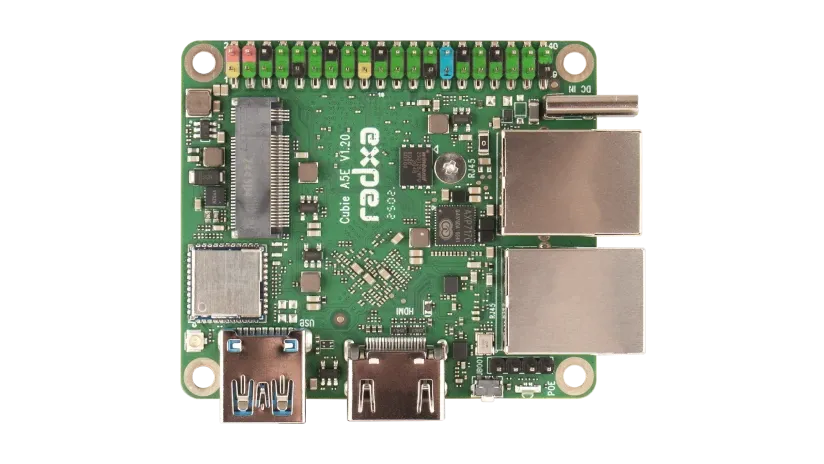
8 Core Tiny AIoT SBC
 kind vessel
Worth checking the Armbian supported page: https://www.armbian.com/download/?device_support=Standard support
No experience with the brand/product but armbian support is a good sign 😉 https://www.friendlyelec.com/index.php?route=product/product&path=69&product_id=309
faint sparrow
turbid rivet
Small and cheap are relative, but ignoring that, gigabyte Ethernet is surprising...
That board last time I checked had no software, the linux images were not yet built
faint sparrow
strong barn
pi zero format doesn't have anything with 2+ ethernet ports AFAIK. At much highe...
I saw that there was this
https://a.aliexpress.com/_Euq5wY6
But yet another cn, product, I dunno if support is great or midly absent/broken
strong barn
Can an actual router meet your needs, instead of an SBC? Maybe you can get an old router running openWRT or something
 vivid hearth
I'm running a Raspberry Pi Zero 2 with Raspberry Pi OS Lite and Blinka. It's serving two USB webcams via Motion and running a few GPIO and IOT scripts. Works fine and usually runs at 30-50% CPU usage and less RAM. Problem is it periodically (1-2 a day) locks up requiring a manual reboot. This never happened when I ran the same load on a RPi4B. I don't know where to start the debugging. The SD card is fairly new so I doubt that's the problem. Any thoughts?
humble marsh
vivid hearth
I'm running a Raspberry Pi Zero 2 with Raspberry Pi OS Lite and Blinka. It's ser...
Could be a power problem if the USB supply is not adquate. Also how hot is the CPU getting?
vivid hearth
humble marsh
Could be a power problem if the USB supply is not adquate. Also how hot is the C...
It did have a problem with heat but I put a 5v fan on it and it typically runs 40-50C now. Power supply is one I've long used for my RPi4B so that should be good.
I also thought it was heat until I added the fan a few days ago.
humble marsh
when it locks up is the console completely inaccessible? Is there anything in /var/log/syslog that's interesting?
trying another SD card would be easy
vivid hearth
humble marsh
when it locks up is the console completely inaccessible? Is there anything in /v...
I actually don't have a /var/log/syslog file. The console is completely locked up when it crashes. Open ssh sessions hang and become unresponsive.
hardy plaza
vivid hearth
I actually don't have a /var/log/syslog file. The console is completely locked u...
In newer OS versions its using journald for logging. You can search on how to go back to the old method and disable journald logs, which are binary files and also take up a lot of space. Then you can actually read the log, fancy that!
vivid hearth
I have noticed that it is often slow to even return keystrokes. I’m wondering if the system is overloaded in a way that *top commands don’t indicate.
I wouldn’t expect lock up behavior though. I typically notice it after nothing updates for a few hours.
strong barn
You can set up core dumping and try to use sysrq magic keys to force a core dump on freeze
then review the core dump for what's going on
then if that doesn't work, you almost certainly have a hardware issue
If you have a spare pi, try swapping it out first though, because if you've never set up core dumping and magic sysrq keys, it's a little bit of an adventure
vivid hearth
strong barn
then if that doesn't work, you almost certainly have a hardware issue
Now that you mention it this is a brand new sbc and may have a hardware issue. I'll swap it for one I've used in the past.
Same design, of course.
vivid hearth
Switched out with another board and it's still having the same behavior. I need to try a different SD card but I hesitate to reinstall everything so I might just clone it and hope it's not a corrupted file.
 vestal cairn
What's the simplest/smallest/quickest OS to use for a Pi Zero 2 for PyGame? Just install alpine then python then pygame?
hardy plaza
vestal cairn
What's the simplest/smallest/quickest OS to use for a Pi Zero 2 for PyGame? Jus...
Why not use the OS designed for the Pi Zero 2? I.e., the Raspberry Pi OS?
vestal cairn
hardy plaza
Why not use the OS designed for the Pi Zero 2? I.e., the Raspberry Pi OS?
Just want the quickest startup time with the least extra stuff
But that's what I'm currently using, yes
hardy plaza
vestal cairn
Just want the quickest startup time with the least extra stuff
I frankly don't think you can improve on the default OS, which was designed for the board and has all the hardware connections, software utilities, etc. If you don't need a GUI use the headless version, it's not big.
vestal cairn
hardy plaza
I frankly don't think you can improve on the default OS, which was designed for ...
Thanks! I will stick with it, then.
Decided against PyGame anyway.
hardy plaza
vestal cairn
Thanks! I will stick with it, then.
You'll definitely want raspi-config and other tools, and as a Linux user myself (and before that, Unix, going back to the 1980s) there's absolutely nothing wrong with the Raspberry Pi OS, works great! And Debian compatible, which is my favourite.
 broken stump
Hello everyone I’m using a raspberry pi 4 and led matrix for a project. I am trying to auto start it once my pi gets power using crontab e but whenever I power it back on the image on the matrix only flashes for about a second. I don’t know how to fix it please help. PS here’s my code
 hardy plaza
broken stump
Hello everyone I’m using a raspberry pi 4 and led matrix for a project. I am try...
hardy plaza
broken stump
Hello everyone I’m using a raspberry pi 4 and led matrix for a project. I am try...
Is it possible your script is just ending? Try adding time.sleep(5) at the end and see if it persists for 5 seconds
broken stump
Omg @hardy plaza that worked if I have a presentation for this that will last around 15 minutes how long should I do a time sleep for?
hardy plaza
broken stump
Omg <@828135237744984114> that worked if I have a presentation for this that wil...
I was really suggesting this just to see what would happen. My suspicion was that you'd gone to the trouble of setting up your LED matrix, you got it going, but then your script exited immediately (it finished what you'd told it to do), shutting off the LED matrix just as soon as it started.
There are a variety of ways to keep a script going. One of them (and only one of them, probably the most basic) is to create an infinite loop. Here's kinda a classic structure for this:
try:

    # put the rest of your script inside here...
    # ...
    matrix.SetImage(image.convert('RGB'))

    while True:
        # this will run until you type Ctrl-C
        time.sleep(1)

except KeyboardInterrupt:
    print('Ctrl-C caught, exiting…')
except Exception as e:
    print('{} raised: {}'.format(type(e), e))
finally:
    print('complete.')
 mild raven
broken stump
Hello everyone I’m using a raspberry pi 4 and led matrix for a project. I am try...
mild raven
broken stump
Hello everyone I’m using a raspberry pi 4 and led matrix for a project. I am try...
Yeah LED Matrixes don't have greyscale only 1-bit buffers and have to be software-PWMed at Mhz speeds so all the libraries reset the display to 'black' when closing the display as otherwise you'd get totally random colors everywhere not the last image you set them to.
hardy plaza
mild raven
Yeah LED Matrixes don't have greyscale only 1-bit buffers and have to be softwar...
One way to keep the display functioning would be to have a Python script that is always running in the background, and periodically reads a filename (a full path) from a file. You could then just edit the file containing the image and when you save it, the next time the image script reads the filename it would update the image.
But yes, as you say, the display needs a continual refresh or it will display nothing.
mild raven
hardy plaza
**One** way to keep the display functioning would be to have a Python script tha...
But that's still the same scenario: You're keeping the display 'open' in the library, once the library closes? Display = black.
hardy plaza
mild raven
But that's still the same scenario: You're keeping the display 'open' in the lib...
Agreed, I'm just suggesting to the user one way of keeping the display running.
 zealous summit
Can someone help me set up my raspberry pi zero 2 w
zealous summit
I want to use it to record the video from an analog security camera
so I got an rca to usb micro capture card
I flashed the sd card for the raspberry but my pc wouldn't recognise my raspberry no matter what I did
and it wouldn't let me update the drivers either
and now it doesn't recognise the sd either
zealous summit
I'm trying to make the ssh connection for the raspberry
but the pc doesn't recognise it
it comes up as 'unknown device'
steady rose
@zealous summit you'll need to figure out how to SSH into the pi:
https://www.raspberrypi.com/documentation/computers/remote-access.html
you can configure network settings in rpi-imager when creating the SD card image:
https://learn.adafruit.com/raspberry-pi-zero-creation/using-rpi-imager
also, having a USB serial cable is a good idea when using a pi headless (no monitor):
https://learn.adafruit.com/adafruits-raspberry-pi-lesson-5-using-a-console-cable/overview
simply connecting the pi to the PC via a USB cable will generally not work
zealous summit
steady rose
<@877555407252488203> you'll need to figure out how to SSH into the pi:
<https:/...
thanks, what's the difference between a serial cable and a data cable?
steady rose
a "data cable" sounds like a standard USB cable
the "serial cable" has a USB-to-serial converter chip in it, it's more than just a USB cable
there are USB gadget modes for the Pi that allow the Pi to show up as some kind of USB device, but those are not the standard way of interfacing with the pi, and require more effort to setup
and most likely not what you want
zealous summit
so I should get a serial cable, do the network stuff on the sd and figure out the ssh for the pi
steady rose
you can try SSH now, no serial cable needed
but if anything happens on the pi, you won't have any visibility
like if it can't connect to your network for some reason
then you won't be able to SSH in and figure out why
try using rpi-imager and use the option to configure networking, enable ssh, etc.
can try pinging it from the PC as a way to test that it's managed to connect to network
ping raspberrypi.local
initial boot / network connect can take a while with a fresh SD card image. like 10's of seconds to a minute-ish.
a fresh image does some stuff and even some reboots, etc. before settling in to normal operation
zealous summit
I see, I'll set the os for the sd and I'll tell you if anything comes up
zealous summit
@steady rose so I'm trying to set up the sd but my laptop doesn't see it for some reason

I might have figured it out
yeah figured it out
ima start doing the stuff on it
zealous summit
Ok I did all the installations and a tutorial told me that I have to edit some files on the sd to make the raspberry pi act as a usb network device
but the pc doesn't recognise the raspberry
steady rose
what tutorial are you following?
zealous summit
chat gpt 🤭
I can't understand anything from the official websites
so I use it to dumb it down to my level
steady rose
are you using rpi-imager to set up the sd card?
zealous summit
yes
steady rose
what operating system did you pick?
 steady rose
did you then go through the various configuration options in rpi-imager? like setting it for your network, enabling ssh, etc?
zealous summit
No I didn't modify those, but I assume I should have enabled ssh
I didn't want to tinker with them since I don't know what they do
well most of them
steady rose
you'll need to use those options to configure the pi to connect to your network
and then ssh in to the pi - which means to connect to it over the network, not via the USB cable
you are not going to be able to connect to it using only the USB cable
zealous summit
I see, I will look further into it and see if I manage anything
zealous summit
I'm having a look at the options rn
is the "Configure wireless LAN" thing related to my wifi network?
actually I might have figured it out, ima let it start writing the os on the sd now
zealous summit
@steady rose alright I flashed the sd and all that, now what?
steady rose
put it in the pi, power pi to boot it up, try to ping pi to verify it connected to network
zealous summit
it doesn't recognise any name I give it
steady rose
if you are unable to find and ping the pi on your network, then you are sort of stuck without some other way of getting into the pi to help troubleshoot
kind vessel
zealous summit
is the "Configure wireless LAN" thing related to my wifi network?
did you do this part? if not, there's a good chance it's not on your network. you can try open command line on your PC and type ping raspberrypi -4 and see if that gives a response with an IP address
(that will only work if you configured the wireless LAN, though)
 lucid nebula
Can someone help me?
I'm getting FileNotFoundError: [Errno 2] No such file or directory: 'db/foia-tickets/json' even though the file exists at that location
 twin helm
lucid nebula
I'm getting `FileNotFoundError: [Errno 2] No such file or directory: 'db/foia-ti...
twin helm
lucid nebula
I'm getting `FileNotFoundError: [Errno 2] No such file or directory: 'db/foia-ti...
that looks like a relative pathname. are you sure that the program has the correct working directory?
lucid nebula
Ye, I was derp and made the realization after a bit of thinking, lmao
zealous summit
kind vessel
did you do this part? if not, there's a good chance it's not on your network. yo...
I did put in the network name and password, I don't think there were any spelling mistakes but I'll check again later
kind vessel
zealous summit
I did put in the network name and password, I don't think there were any spellin...
you can use an app on your phone (WiFiman, Net Analyzer, some others I'm sure) to scan for the device on your network, can also use AngryIP scanner (PC/Mac/Linux) https://angryip.org/, or logging into your router to check too. 🙂 I believe most (all?) rasp pi devices MAC address starts with b8:27
zealous summit
kind vessel
you can use an app on your phone (WiFiman, Net Analyzer, some others I'm sure) t...
I did try some app to scan the devices on my network but I couldn't seem to find the raspberry
zealous summit
Set up your Raspberry Pi in only a few minutes. I will show you how to set up Raspberry Pi OS, wifi, SSH, and VNC, all without plugging your Pi into a mouse, keyboard, or monitor. Just follow these simple instructions and you'll be up and running in no time!
Consider subscribing if this is helpful: https://www.youtube.com/samwestbytech?sub_con...
is this tutorial good for what I'm trying to achieve?
steady rose
yes
vestal cairn
Linux question: I can turn off the cursor blink by uisng setterm -cursor off and I can clear the screen using clear. Is there a way to target those commands to the shell that's controlling the attached screen? If I attach a keyboard, that works, obviously, but I'd like to be able to do it when SSHed in as well.
 wanton current
vestal cairn
Linux question: I can turn off the cursor blink by uisng `setterm -cursor off` a...
wanton current
vestal cairn
Linux question: I can turn off the cursor blink by uisng `setterm -cursor off` a...
Try finding the device name of the current terminal using tty or pstree and then using that with setterm.
*try
vestal cairn
Those get the SSH terminal, not the one attached to the screen, right?
hardy plaza
vestal cairn
Those get the SSH terminal, not the one attached to the screen, right?
I'm not sure if this is what you're asking for, but you can type
tty
to obtain your current pseudo-terminal (PTY), the one assigned to your ssh session. For example, I'm connected to a Raspberry Pi over ssh and I get:
 🍏 tty
/dev/pts/0
does it matter if I'm connected or not to the internet while flashing the sd? I have the software pre downloaded and so far I've been flashing it offline
I have a feeling that was the issue all along
vestal cairn
hardy plaza
I'm not sure if this is what you're asking for, but you can type
```sh
tty
```
t...
Right, but I want the one connected to the monitor, not my SSH one
hardy plaza
vestal cairn
Right, but I want the one connected to the monitor, not my SSH one
Thanks, understood.
steady rose
zealous summit
does it matter if I'm connected or not to the internet while flashing the sd? I ...
if you have already downloaded the image, internet connection should not be needed to flash the SD card. but you'd want to be sure to select "Use custom" option in the "CHOOSE OS" step (it's the last option, so must scroll to bottom of option list) and then navigate and select the pre-downloaded OS image file
zealous summit
yes
zealous summit
it still isn't working
flashed it from a different laptop
different network
it doesn't recognise the name even though it's the same thing
doesn't respond to ssh ping
kind vessel
Couple ideas/things to look out for:
- SSID (wifi name) is case sensitive, so "My WiFi" is not the same as "my wifi" for example. (Password too, but that's probably more obvious :))
- Some devices have problems connecting or staying connected if you use the same SSID for both 2.4GHz and 5GHz devices. (band steering) I recommend using separate SSIDs for each if you're able.
- mDNS only works in same subnet by default, and is often blocked since it is a broadcast, so pinging hostname isn't reliable in a lot of instances.
- log into your router/access point and see what clients are connected and if you can locate the IP that way.
zealous summit
kind vessel
Couple ideas/things to look out for:
- SSID (wifi name) is case sensitive, so "M...
Thank you
I'll try these out
zealous summit
kind vessel
Couple ideas/things to look out for:
- SSID (wifi name) is case sensitive, so "M...
while flashing the sd, do I need to select a device too? Because nothing shows up in that section
steady rose
zealous summit
while flashing the sd, do I need to select a device too? Because nothing shows u...
no. that option only affects how rpi-imager behaves with respect to other options - like only showing supported OS images in the drop down. it does not matter when manually selecting the OS image.
you should be getting the OS images from here:
https://www.raspberrypi.com/software/operating-systems/
compatible pi models are shown
i never use that feature. i have the images already downloaded. i just select the image (CHOOSE OS->Use custom) and the sd card (CHOOSE STORAGE).
 zealous summit
yes
zealous summit
steady rose
you should be getting the OS images from here:
<https://www.raspberrypi.com/soft...
that is exactly where I got it from
and followed the same steps
steady rose
your os imaging process should be fine then
(assuming os image is compatible with pi model being used and was downloaded correctly)
zealous summit
should be, but I still can't manage to get the raspberry to respond to my ping after flashing the sd
even tried on a whole different device and network
steady rose
troubleshooting such things without access to the pi is difficult. it's a black box and you're trying random things and hoping for the best.
if you want to continue with the headless setup, highyl recommend getting a serial cable
the other option would be to connect a monitor/mouse/keyboard
kind vessel
Headless setup really isn't ideal for your first go around, that's generally more for experienced users and advanced use cases. I agree, keyboard/mouse/HDMI would be my recommendation to at least get in and see what's going on after you're imaging. Is it booting up? Erroring out? Wrong wifi credentials? Using the display should make it easier to figure that out 🙂
zealous summit
kind vessel
Headless setup really isn't ideal for your first go around, that's generally mor...
so after before I flash it
I double check my network name
so it's exactly the same
and then
I type out the password and paste it in
so I don't mess up on accident
then I do the flashing
put the sd in the raspberry
let it read or whatever it's doing and after like a minute it makes the usb sound
steady rose
what do you mean by "makes the usb sound"? it seems like you are expecting the pi to show up on your pc like a USB device?
you should also set hidden and country in the wifi settings as needed for your setup
zealous summit
steady rose
what do you mean by "makes the usb sound"? it seems like you are expecting the p...
No I'm just saying that when I hear the usb connected sound I know that the raspberry has finished doing whatever, I use thr data port on the pi to supply power to it
zealous summit
steady rose
you should also set hidden and country in the wifi settings as needed for your s...
what is the hidden thing? I have completed everything else but that
ssh enabeled
country/region
everything but hidden
steady rose

if needed
depends on your wifi setup
I use thr data port on the pi to supply power to it
^^ don't do that. power normally via the other usb connector.
you can ignore the "data" usb connector at this point
if your only power is the USB port from the PC, it may not have enough current output to fully power the pi
strong barn
zealous summit
let it read or whatever it's doing and after like a minute it makes the usb soun...
how does it make the USB sound? The raspberry pi zero 2 W doesn't have any speakers.
And agree with cater, don't power via the data port.
zealous summit
strong barn
how does it make the USB sound? The raspberry pi zero 2 W doesn't have any speak...
the pc makes the sound
like when you connect a keyboard
zealous summit
steady rose
if your only power is the USB port from the PC, it may not have enough current o...
heard, I'll re flash later today
zealous summit
steady rose
if your only power is the USB port from the PC, it may not have enough current o...
if nothing else works should I take photos of every step I take
steady rose
unless you've done something significant to alter the hardware, that would not help.
the only solution to "headless pi not connecting to network" is to somehow access the pi (serial cable, monitor/mouse/keyboard) and determine why
it should be as simple as (1) configure wifi settings in rpi-imager, (2) burn image to sd card, (3) boot pi with sd card
(if anyone watching knows a way to headless-ly enable a USB CDC device gadget with a console login, i'd be interested in how)
zealous summit
(same)
zealous summit
steady rose
the only solution to "headless pi not connecting to network" is to somehow acces...
like this ?
 steady rose
no
like this:
https://www.adafruit.com/product/954
if you have header pins on the pi, this is also an option:
https://www.adafruit.com/product/3589
identical to the cable in terms of hardware, just packaged differently
cable is generic
the PID 3589 is pi specific
zealous summit
steady rose
like this:
<https://www.adafruit.com/product/954>
does this have some other circuit inside that blue case or is it just wires
steady rose
there is circuitry and a specialized chip (the CP2102)
zealous summit
dang
steady rose
can see it all on the PID 3589 pcb
for the PID 954, its all in the chonky plastic bit
there's stuff in there. more than just wires.
 zealous summit
Yeah I had a feeling
what about this thing

description :
The Prolific PL2303 USB-TTL Serial Converter Cable allows you to use a USB interface as a TTL interface. This cable allows you to connect any TTL interface device, such as a sensor or development board, to your computer and start communicating with each other. The module is compatible with a wide range of devices, as it uses 5V logic and power supply. One end of the cable features a standard USB Type A connector, while the other end has a female pin connector.
Note: This cable does not include a DTR (reset) wire, so it cannot be used as a programming device.
steady rose
yah, it would damage the pi
steady rose
there are lots of "USB to serial" chips and hardware based on them
the PL2303, the CP2102, etc.
they all do nominally the same thing: USB-to-TTL serial
but the logic level needs to be 3V for usage with a pi
hearty schooner
search amazon for "3v usb serial" ... there are lots
zealous summit

CH340G USB to TTL Converter Module – USB to UART Serial Interface (3.3V / 5V)
The CH340G USB-TTL Converter Module is a robust USB-UART interface board designed to facilitate serial communication between microcontrollers and personal computers. Leveraging the power of the CH340G chip, this module provides seamless USB connectivity for a wide range of embedded systems, including but not limited to Arduino, ESP8266 and ESP32, that require UART communication.
Feedback
zealous summit
hearty schooner
search amazon for "3v usb serial" ... there are lots
they don't deliver here
hearty schooner
ah
zealous summit
they don't deliver components either
steady rose
does that one allow setting 3/5 via that jumper?
zealous summit
yes
steady rose
is there a better image showing the pinout info?
zealous summit
Input Voltage: Configurable 3.3V / 5V via jumper
zealous summit
steady rose
is there a better image showing the pinout info?
couldn't find one
steady rose
input voltage comes from USB and is 5V
its the voltage output (logic) that needs to be 3V
zealous summit
yes
steady rose
it seems like maybe that one would work
zealous summit
yeah, but I would need a pinout sheet
steady rose
the CH340G is yet another usb-to-serial chip
zealous summit
it's what I'm looking for right
steady rose
it may be printed on the PCB and just not visible in product photo
hearty schooner
it'll be documented somehow
steady rose
two pins seem to be for the jumper. so would assume the other 4 are GND, PWR, TX, RX
zealous summit
yes
steady rose
if you're powering the pi separately, you generally ignore the PWR pin on these
and only connect GND, TX, RX
most of these are not able to supply enough power to drive a pi
zealous summit
yo I found the data sheet online
steady rose
and you'd want the PWR pin to be 5V
datasheet for that product? or datasheet for the CH340G?
zealous summit
nvm it's usb to uart
steady rose
uart = serial
steady rose
looks like datasheet for just the CH340G
even though it does show some example usage circuits
zealous summit
so that's why it had like 20 pins
steady rose
yep. that's the pinout / pin count for the CH340G itself
zealous summit

I think this is the circuit of the module
on a different website I found the same product
steady rose
looks probable
zealous summit
and in the description it said "yo data sheet at this website"
and then I found it

yippe
it has the pinout on the back
steady rose
seems like that might work
steady rose
zealous summit
fire
steady rose
and then power the pi separately