#help-with-linux-sbcs
1 messages · Page 1 of 1 (latest)
 viral oxide
To clarrify, the leds dont all need to be independantly controlled, will it work if i just connect multiple led and resistor pairs
 umbral sable
viral oxide
To clarrify, the leds dont all need to be independantly controlled, will it work...
umbral sable
viral oxide
To clarrify, the leds dont all need to be independantly controlled, will it work...
Yes, that will work, as long as you don't exceed the current capacity of the GPIO.
viral oxide
umbral sable
Yes, that will work, as long as you don't exceed the current capacity of the GPI...
What would that be exactly
umbral sable
viral oxide
What would that be exactly
It looks like the RP2040 pins have selectable drive strengths from 2 to 12mA.
 wanton kayak
Hello, I have custom PCB with RP2040, the USB works in bootloader mode, flash of firmware works good (when I dump it is OK), but after testing the hello world USB, there is no USB activity. Any ideas? Eventually, can bootloader USB mode work without external oscillator?
 fickle rose
I don’t think the rp2040 has a internal oscillator
 twin helm
according to the datasheet, it does, but i'm not sure it's stable enough for clocking USB (maybe low-speed only?)
 hard pike
twin helm
according to the datasheet, it does, but i'm not sure it's stable enough for clo...
hard pike
twin helm
according to the datasheet, it does, but i'm not sure it's stable enough for clo...
According to the datasheet, you need the external osc to enable USB, it's how USB PLL is fed
as far as I am aware, there is no way to enable USB with the internal osc
twin helm
ah, ok. ATmega32U4 has an internal oscillator that can be used for low-speed USB only
hard pike
It's a point of ire among people who are used to using the SAMD21 and getting USB with minimal components
SAMD21 from what I understand use USB timing to calibrate the internal osc
no idea if it's the same on the 32u4
twin helm
hard pike
SAMD21 from what I understand use USB timing to calibrate the internal osc
heh. "the host has to have a more stable clock than we do; let's use that!"
hard pike
basically lol
twin helm
the 32u4 doesn't automatically calibrate its internal oscillator from the USB timing, but you could probably write firmware that did
wanton kayak
BTW, the issue was bootloader second stage had issues to init SPI Flash
#define PICO_BOOT_STAGE2_CHOOSE_GENERIC_03H 1

#ifndef PICO_FLASH_SPI_CLKDIV
#define PICO_FLASH_SPI_CLKDIV 2
#endif
 visual crescent
Could I use this for a pi? it's meant for an arduino, and I don't care for the touch, but it's the only affordable 3.0" lcd I could find

Pinout
 fickle rose
While you “could” you would have to write a library to use it with the raspberry pi so I wouldn’t recommend it
visual crescent
fickle rose
While you “could” you would have to write a library to use it with the raspberry...
Understood
 mint field
There is a C library here https://github.com/nopnop2002/Raspberry-ili9325 which would be a good starting point
GitHub
Parallel TFT Shield Library for wiringPi. Contribute to nopnop2002/Raspberry-ili9325 development by creating an account on GitHub.
 hollow jewel
how i create a ap local host with a pico w?
visual crescent
mint field
There is a C library here https://github.com/nopnop2002/Raspberry-ili9325 which ...
No worries, found the perfect library for my purposes, I'll post it here if anyone needs it: https://github.com/juj/fbcp-ili9341
It's meant for the ili9341 tho, but it does have other drivers supported too

GitHub
A blazing fast display driver for SPI-based LCD displays for Raspberry Pi A, B, 2, 3, 4 and Zero - GitHub - juj/fbcp-ili9341: A blazing fast display driver for SPI-based LCD displays for Raspberry ...


Can I wire up that sd card breakout board to these pins to relocate the main sd card reader?

There's also a simpler pcb with less resistors, not sure why and how they differ
 fickle rose
you need a breakout that shows the SDIO pins
here is one: https://adafru.it/4682

Micro SD cards and microcontrollers go together like micro-peanutbutter-and-jelly: SD cards are inexpensive, durable, easy to find at any shop, come in many sizes and can plug into any ...
i can't think of a reason it won't work if you use the SDIO breakout
or you could use https://adafru.it/3688

Stop fiddling with SD card sockets in the back of your latest gadget, and streeeeeeeeeetch out with a Micro SD Card Extender . This simple, but effective device gives you a long ...
 spare girder
1M. I found an application for my PC called MOBAXTERM something like that which allows me to connect to my PI over wifi instead of cable. am loving it!! but i need to shut down my HDMI and make something to let me reconnect to hdmi incase if wifi crashes. or does the pi detects that hdmi cable is unplugged and boosts his performance?
 latent quail
This is just a comment, rather than a question, but someone might want to update the library documentation or the implementation guide for the LIS3MDL breakout - Python/Circuitpython. there is a note on the Arduino guide about a known issue that is resolved by grounding the A0 pin (or pulling high, I guess). It appears this also applies to Python/CircuitPython as it appears to be a hardware issue. Some functions communicate correctly with the sensor, while some do not. The sensor also appears to change I2c addresses from the perspective of the OS (outside of python). This was resolved for me by either grounding or pulling the A0 pin high (and thus fixing the address to either 0x1c or 0x1e)
 humble marsh
latent quail
This is just a comment, rather than a question, but someone might want to update...
humble marsh
latent quail
This is just a comment, rather than a question, but someone might want to update...
does your breakout look like the one with the STEMMA connectors here: https://learn.adafruit.com/lis3mdl-triple-axis-magnetometer
I will ask about that. It looks like there's a pulldown on the pin already, but there may be some further issue
this is the AD1 jumper on the back, right? Did you short the jumper, or connect one end directly to GND?
 radiant helm
Hey guys! I'm looking to buy a Pico W and get it working with circuit python for Arducam functionality, does circuit python have support for the Pico W?
 sacred oar
radiant helm
Hey guys! I'm looking to buy a Pico W and get it working with circuit python for...
sacred oar
radiant helm
Hey guys! I'm looking to buy a Pico W and get it working with circuit python for...
Looking at circuitpython.org I don't believe it currently does
radiant helm
shoot, thank you for the quick response though!
 steady rose
i think this is the relevant issue fwiw:
https://github.com/adafruit/circuitpython/issues/6558
latent quail
humble marsh
this is the AD1 jumper on the back, right? Did you short the jumper, or connect ...
I have two, one with the jumper soldered and one without. Neither works appropriately using only the jumper. They appear as the "correct" address initially upon bootup (tried with 3 SBCs of different manufacturers" and then later switch to a different address. simple functions like reading out the data rate work, but I could not get mag readings on either. Setting the D0 external pin either to ground or pulled high to the logic voltage worked to set a stable I2C address on both that would work for all library functions
humble marsh
latent quail
I have two, one with the jumper soldered and one without. Neither works appropri...
thanks - I have asked internally about the details of this and am awaiting an answer. In any case, thanks for your report, and we'll try to make the guide better
...
ok, I see this person had trouble too, and notes that with the 10k pulldown on the address pin, the actual voltage measured there is about 1.2v, not great: https://forums.adafruit.com/viewtopic.php?f=19&p=856682#p854887
Datasheet says: When I2C or 3-wire SPI is used, the SDO/SA1 in must be connected to Vdd_IO or GND. I will note this in the guide in both sections and in the pinout section.
latent quail
Awesome. Yeah, I saw the note in the Arduino/C++ guide and decided to try that to fix the address rather than relying on the jumper, and it solved the problem.
 thick dagger
Hi I am trying to make a game console with the pi 4 but In order to make it fit I need to desolder the USB ports on the pi. Is there a good way to do this?
umbral sable
thick dagger
Hi I am trying to make a game console with the pi 4 but In order to make it fit ...
The best way would be with a hot-air gun, I'd say.
visual crescent
fickle rose
you need a breakout that shows the SDIO pins
Thank you. Can this wire directly into the main SD card reader? What is the pinout on the pi?
visual crescent
fickle rose
It’s the cluster of pins to the right in the photo
I know that, but, what do I wire each pin to? Not all are obvious
I just realised the board I found was spi. From what I can tell, there's only one sdio board in my country website
 daring fable
To anyone who has been considering a CrowPi L (Raspberry Pi laptop) and think you can just use the pins with regular devices like the Sensor HAT think again. After speaking back and forth to Elecrow, even after they created an adapter, they have finally decided to tell me that there are pins disabled.
"Allow me to explain, when designing CrowPi L, several pins are disabled: 4, 6, 17, 39. Because if these power pins are plugged in incorrectly, it'll be easy to burn Raspberry Pi."
This makes this device useless to me so I'll be returning mine.
 fickle rose
visual crescent
I just realised the board I found was spi. From what I can tell, there's only on...
fickle rose
visual crescent
I just realised the board I found was spi. From what I can tell, there's only on...
here is a link to one on adafruit https://adafru.it/4682
Micro SD cards and microcontrollers go together like micro-peanutbutter-and-jelly: SD cards are inexpensive, durable, easy to find at any shop, come in many sizes and can plug into any ...
fickle rose
daring fable
To anyone who has been considering a CrowPi L (Raspberry Pi laptop) and think yo...
the pins are disabled to protect the pi
visual crescent
fickle rose
here is a link to one on adafruit https://adafru.it/4682
I've seen it, but I don't want to order from overseas, I live in asia and the shipping is usually overly expensive. I can't seem to find that model here sadly
I have a question tho
fickle rose
?
fickle rose
visual crescent
I have a question tho
what is it?
visual crescent
fickle rose
what is it?
https://www.youtube.com/watch?v=uZBYOqfhCSo&t=370s
At about 0:24, he explains how he did it, he didn't seem to use a conventional card reader with an interface, instead he practically directly soldered a Micro SD card to SD card reader directly to the Pi's back things that I showed before

Follow what I’m up to between videos on Instagram! https://www.instagram.com/sudomod_wermy/
Want to help support future projects? Buy me a coffee! https://buymeacoff.ee/NcFE38xiO
See what other sudomodders are up to in the forums! https://sudomod.com/forum/
Written guide:
http://sudomod.com/game-boy-zero-guide-part-5/
Enter to win the one I'...
Why did it work for him?
What he is doing is what I am trying to do as well, however I was having trouble with the pins
fickle rose
visual crescent
What he is doing is what I am trying to do as well, however I was having trouble...
wym
visual crescent
fickle rose
wym
He is basically relocating the sd card reader to a game boy cartridge slot
fickle rose
he isn't booting the pi from that sd card
it's on the gpio and the pi can't boot from an sd card on gpio
visual crescent
Oh, are you aware of this project?
visual crescent
Oof
fickle rose
pulled the L button pad right off
visual crescent
How does his work, since those are adapters, no?
fickle rose
wait i was wrong
visual crescent
About?
fickle rose
he is booting the sd card from the cartridge using the pins on the bottom
do you have a microsd to sd adapter?
visual crescent
I might, I have to look for it or buy one
fickle rose
you won't need the breakout then
just solder to the pins on the adapter like wermy did
visual crescent
Oki!
 fading idol
I have a CRICKIT HAT (product 3957) and have it on a Raspberry Pi 4. If I try to use power from the CRICKIT, it will not boot. If I provide USB power to the Pi 4 and the CRICKIT, I can get it to boot. Is there something I can do to provide power to the Pi from the CRICKIT? Should I use a Pi 4 with the CRICKIT or is it better to stick with the Pi 3?
steady rose
what power input are you using on the HAT?
make sure it's the barrel connector
the HAT should be able to back power the pi
fading idol
steady rose
<https://learn.adafruit.com/adafruit-crickit-hat-for-raspberry-pi-linux-computer...
I am using Product ID: 1466 (5V, 4A) with a barrel connector. Thanks
wanton kayak
Hello, please, is anyone there who have experience with RP2040's PIO ?
hard pike
wanton kayak
Hello, please, is anyone there who have experience with RP2040's PIO ?
Post your questions and any code you have. You’ll get help faster 🙂
 hybrid swan
@humble marsh mentioning you as well since you created the library and might have some insights on this too. I am working on a project that uses a RPi Pico W and an LCD. The LCD I'm using (PFC8574) requires 5V. From everything I've read about the Pico you can basically use VBUS or VSYS pin for 5V when powered from USB. When displaying simple text on the LCD it's getting garbled. I send "This is a test" and on the LCD it shows "Thisa te". Sometimes running the same code results in strange characters randomly placed on the screen. I think it's due to voltage as I have 2 of these LCDs and they both do the same thing so I'm wondering if I need to add an external power supply to the project. Anyone else run across this? And here's the code: from lcd.lcd import LCD, LCD_BACKLIGHT, LCD_NOBACKLIGHT
from lcd.i2c_pcf8574_interface import I2CPCF8574Interface
from lcd.lcd import CursorMode
import busio
import board
Here we will build an interface for the supported display
i2c = busio.I2C(board.GP27, board.GP26)
lcd = LCD(I2CPCF8574Interface(i2c, 0x27), 4, 20)
lcd.clear()
lcd.set_cursor_mode(CursorMode.HIDE)
lcd.print("This is a test")
steady rose
fading idol
I am using Product ID: 1466 (5V, 4A) with a barrel connector. Thanks
hmm..seems like that should work. what's your indication that the pi does not boot?
fading idol
I have it hooked to keyboard and monitor and I do not get anything other possibly a flash as it powers on. Also,no light on the Pi
steady rose
anything special about how the crickit is attached to the pi? or is it just like this?
https://learn.adafruit.com/assets/67677
fading idol
It is like that. I have buttons hooked to 4 of the IO pins and LED lights wired up to 4 of the PWM (technically wired, but no buttons or lights connected at the other end).
steady rose
when you power both so the pi boots, does the crickit then work ok?
fading idol
Yes, as long as I put power to the Pi first, I am able to plug in the CRICKIT and it operates just fine.
steady rose
not sure what's up. would you mind posting this in the forums so we can work it there?
fading idol
Absolutely! Thank you for your help
steady rose
fading idol
Absolutely! Thank you for your help
np. can ping me with link to post and i'll follow up there. thanks!
visual crescent
Anyone know if I could use a Nintendo DS Lite screen for a Raspberri Pi? I have no idea what kind of screen it is for now
Nevermind, seems to be a 45 pin thing, probably proprietary like most Nintendo stuff
visual crescent
visual crescent
Nevermind, seems to be a 45 pin thing, probably proprietary like most Nintendo s...

 frozen shoal
Hi, so new to all this but I'm looking at this guide https://learn.adafruit.com/reading-a-analog-in-and-controlling-audio-volume-with-the-raspberry-pi?view=all and in the guide it shows wiring up a potentiometer to one of the channels
So I'm wondering if I say wire up another potentiometer and put it on channel two, how would the raspberry pi differentiate between the two signals?
Also would the wiring and everything pretty much be the same for say a 16 channel one like this one? https://www.mouser.com/datasheet/2/256/MAX11120-MAX11128-217961.pdf
Lastly in the guide there's code and it says at the top import adafruit_mcp3xxx.mcp3008 as MCP I don't really know where to look but is there a library for the 16 channel max111xx chip?

Adafruit Learning System
Convert analog inputs to digital and control audio volume
steady rose
the pi doesn't differentiate. the MCP3008 does.
the pi talks to the the MCP3008 over SPI
so the pi would say like "give me the value on channel 0", etc.
the basic wiring that's being done is what's called a "voltage divider" - can google that for tons of info. it's a generic thing, so, yep, could be used with other ADC's
frozen shoal
steady rose
the basic wiring that's being done is what's called a "voltage divider" - can go...
I see, but would I need a library to use another ADC though?
steady rose
yep
frozen shoal
I'm not able to find a library for the MAX11128 chip
steady rose
yep. i'm not aware of one either. would need to search around.
steady rose
the MAX appears to be SPI based, so, in theory, could work
do you need more channels?
frozen shoal
I don't really know anything about this kind of stuff but I was looking at mouser and found that MAX chip, it'd be cheaper to use that then use two MCPs
frozen shoal
steady rose
do you need more channels?
Yeah, 16
Do you know of a chip that has a library for it that's cheap?
steady rose
SPI allows for multiple devices
SCLK/MOSI/MISO pins get shared
and then each device needs its own CS pin
so, yes, could use two MCP3008's
frozen shoal
I see, but it'd still need a library so I can't use the MAX right?
steady rose
correct. that'd be true in general. for any given device, need a library to support.
frozen shoal
steady rose
SCLK/MOSI/MISO pins get shared
Also on the guide it says those pins but I'm thinking about using a pi pico and on it's pinout it doesn't show SCLK, MOSI, or MISO https://datasheets.raspberrypi.com/pico/Pico-R3-A4-Pinout.pdf
Am I correct at least that SCK means SCLK?
steady rose
they're DIN and DOUT in the MAX datasheet for example
frozen shoal
The guide says MISO is DOUT and MOSI is DIN
I mean like uh where do I connect those to the pi pico?
frozen shoal
steady rose
they're DIN and DOUT in the MAX datasheet for example
Yeah on the datasheet I can see that it says DIN and DOUT, but I can't find that on the pi pico
steady rose
 frozen shoal
If I had to guess TX is transmit so that's DOUT and RX is receive so DIN?
steady rose
TX and RX
^^ SPI pin naming has a bit of a history to it
pico SPIx_TX would be out of the pico (i.e. MOSI)
RX would be in (i.e. MISO)
frozen shoal
Oh I see
Wait, if TX is out of the pico, why's it called DIN?
I'd assume since it has IN, it well means in?
Sorry for all the questions, all this stuff is confusing to me
.<
steady rose
where are u seeing DIN?
frozen shoal
steady rose
where are u seeing DIN?
OHHH
I see it now
MCP3008 DIN -> MOSI (white)
It's DIN on the MCP side
So TX out of the pico and into the DIN side of the MCP
steady rose
yep. think in relative terms. relative to the device with the name.
steady rose
the TX/RX nomenclature is very confusing
frozen shoal
Ahh
Oh, also would it break anything if I got those two mixed up?
Like by accedent?
I'd assume it just won't work right?
steady rose
yep. most likely.
steady rose
it helps to understand SPI in general
then you just go with the flow on all the different names
frozen shoal
Would you happen to know if I'd still be able to program the pico if I use one of these?

*Note: Does not support OTG connections such as memory sticks, external hard drives, keyboard or mouse. USB C to Micro USB Adapter The adapter from JXMOX lets you use your existing USB-C cables for charging and syncing your Micro USB devices, without the need to carry an extra Micro USB cable wit...
Not sure if they only pass through power or both power and data?
steady rose
cause u only have USB C cables?
frozen shoal
steady rose
it helps to understand SPI in general
Ye, I'm gonna have to do more research on all of this
XD
frozen shoal
steady rose
cause u only have USB C cables?
Well no, it's just that I'd rather use usb c
steady rose
hopefully they'd just work. but USB C has some fancy features that can sometimes cause hiccups.
most likely, they'd just work though
frozen shoal
steady rose
hopefully they'd just work. but USB C has some fancy features that can sometimes...
I see, so basically would a safer bet be this?
What a cutie pie! Or is it... a QT Py? This diminutive dev board comes with one of our new favorite chip, the RP2040. It's been made famous in the new Raspberry Pi Pico and our ...
Only issue is that it'd be double the price of a pico + adapter though
Trying to limit the amount of money I'd waste if I break something
XD
frozen shoal
Well I don't think the adapter would break anything, it's mainly soldering onto the pads and ruining a $4 board verses a $10 board
steady rose
yep. and the qt py breaks out fewer pins of the RP2040.
but it has a reset button and stemma connector
and the pins are actually labeled 🙂
trade offs
frozen shoal
Yeaa
But it does have enough pins to use two MCPs right?
Each takes four so I'd need eight?
steady rose
something like that
 frozen shoal
steady rose
something like that
frozen shoal
steady rose
something like that
Whoaaa
steady rose
that's just the SPI pins
frozen shoal
I didn't know you could share the yellow blue and green pins
Thought they had to be seperate
XD
Also
How'd you make that?
steady rose
fritzing
the orange/white wires are the "chip select" (CS) wires
those are the ones that needs to be unique
and can be any available GPIO (digital) pin
frozen shoal
steady rose
fritzing
Oh, that's neat
steady rose
nothing special about using A0/A1
steady rose
on the software side, the CS pin is one of the parameters used when setting up the MCP:
https://github.com/adafruit/Adafruit_CircuitPython_MCP3xxx/blob/93bd5c833863ce0517d8e9bbbe0ea89768e483ef/examples/mcp3xxx_mcp3008_single_ended_simpletest.py#L17
two MCP's would look something like:
mcp1 = MCP.MCP3008(spi, board.A0)
mcp2 = MCP.MCP3008(spi, board.A1)
Alright, think I've got it now
Also, by chance would you know how to wire load cells?
steady rose
if it's a basic bridge type load cell, can use this:
https://www.adafruit.com/product/4538
frozen shoal
steady rose
if it's a basic bridge type load cell, can use this:
<https://www.adafruit.com/p...
It'd be these

This load sensor, sometimes called a strain gauge, is the same one found in digital bathroom scales (you know, the ones you use in January for your New Yea
So currently the plan is to use four of them on each corner, going to an LM324 (I think that's what that amplifier chip is called) then go to the MCP3008
I'm wondering if I can somehow average the signal of all four sensors so I can use one channel instead of four rather then have the pico average it internally
If that can be done I think I could get by with only using a single LM324 and an MCP3004
steady rose
that one is only 3 wires. a little different.
but looks like SF has a good write up about it, and load cells in general
frozen shoal
Ohh
So it seems like I have to use something like this https://www.sparkfun.com/products/13878

The SparkFun Load Sensor Combinator is a bare PCB that combines four load sensors into a standard four-wire [Wheatstone bridge configuration](http://en.wik
I thought it would have been as simple as putting the wires in parallel
XD
Huh
Wait a minute
Get that, put the output to the LM324, now amplified, go straight through to the adafruit pico???
Would that make it so that I'd only need one channel now?
steady rose
sounds you're basically wanting to do this?
https://cdn.sparkfun.com/assets/learn_tutorials/5/4/6/SparkFun_Wheatstone_Bridge_Load_Sensor_HX711_bb_Fritzing.jpg
don't need the actual load values from the individual load cells?
frozen shoal
steady rose
sounds you're basically wanting to do this?
<https://cdn.sparkfun.com/assets/lea...
Actually yeah
frozen shoal
steady rose
don't need the actual load values from the individual load cells?
Nope, I don't think I do, average should work just fine
The only difference is that instead of using that load cell amp it'd be with one of these
Well apparently I'm sending links too fast but it's the datasheet for the LM324
.<
steady rose
is using the LM324 a requirement?
frozen shoal
steady rose
is using the LM324 a requirement?
Noap, but it's cheap and I need four channels still for it, as I plan to use multiple load cells in pairs of four, so 16 load cells in total
So it's be four load cells -> combinator -> one of the channels to the LM324 -> then going straight to the ADC of the adafruit pico
So from my research the regular pico only has three usable ADCs but the adafruit pico has four of them
Only other question I have is how to figure out how to combine the 12 wires of the four load sensors into four wires without the combinator
It seems like it's just a bare pcb with no chips on it so I assume there's a way to do it but the board just makes it neater?
steady rose
frozen shoal
steady rose
schematic is here:
<https://cdn.sparkfun.com/datasheets/Sensors/ForceFlex/SparkF...
If I'm reading that right, would E+ be positive, then E- be negative, then A- and A+ would go to pin two and three respectively on the LM324 to which pin one would go to one of the qt rp4020's ADC pins?
umbral sable
I think you would need a resistor feedback network on the op-amp as well to define what gain and offset it is providing to the load-cell inputs, and then the resulting output (which is now in a good voltage range) would go to an ADC pin.
frozen shoal
umbral sable
I think you would need a resistor feedback network on the op-amp as well to defi...
From the research I've done, I think a one mohm resistor should do the trick and get like a 200x gain?
Though I'm still kinda unsure if that's correct and how it works
Uh, worse thing that can happen is that if it's too low is that I'll lose precision (though I don't think that'll matter very much) and if it's over maybe break the qt rp2040 board?
😅
umbral sable
It would be wise to measure the output with a multimeter before hooking it to your board, yeah. If it's working okay you can see it change as you press on the sensors, and you can verify the range of voltages.
frozen shoal
umbral sable
It would be wise to measure the output with a multimeter before hooking it to yo...
Yepp, gonna do that before soldering it to the board
XD
frozen shoal

So uh
Does that look right?
Also yes I do want to turn the four leds on with one pin
twin helm
it's better to give each LED its own current limiting resistor, to balance the currents in case their forward voltages are slightly different. but that might work for a quick test
 signal karma
Anyone know when the pi shortage will end?
hard pike
signal karma
Anyone know when the pi shortage will end?
Probably not till next year
Unfortunately demand has attracted scalpers. until demand broadly falls, I wouldn’t anticipate it getting better for a while
signal karma
hard pike
Unfortunately demand has attracted scalpers. until demand broadly falls, I woul...
Am thinking it’s more of an explosion of awareness and usage that. Scalpers. On the 3D printing geoups ie voron they are acticely looking for places with them in stock for builds. That has exploded in the past 3 years.
hard pike
You have looked at eBay and non-authorized reseller sites, yes?
Adafruit and Pimoroni both took steps to stop scalpers because people were buying and reselling them for ridiculously high prices
Yes, demand has exploded. But scarcity in tech products over the last 2 years has been driven a lot by bot buyers
Looking to make a buck in hot products.


This is Pi 4 sold recently
And there at 1000s more in this list of “sold” on eBay
People are desperately needing/wanting Pi 4 so they’re willing to pay huge markups
Geez, even unopened Pi 4 from Adafruit on that list of recently sold for huge markups
 opaque wagon
I often see 5x markup on these things 😬
 unique tulip
Yeah, if I saw a Pi 4 on sale from a non-scalper I'd probably just pick one up "in case"
frozen shoal
twin helm
it's better to give each LED its own current limiting resistor, to balance the c...
I see
Alright, thanks!
^-^
<3
 azure basin
I thought this command line could be handy to keep in your grimoires:
cat /proc/cpuinfo | grep Model
Let's you know what pi you have in case you have forgotten and can't see it in a case, or a skull, or a pi controlled model.
Also, if a Hat is installed and if If is in spec and has an EPROM setup properly, you can use /proc/device-tree/hat/ to identify the Hat, and it's function
 hollow otter
Can anyone tell me where I can find the source code for the framebuf library used in micropython?
I want to extend it to add rotation.
 final solstice
Hello friends. It has been about six months since I checked on supply chain issue updates. I wonder, do we have any light on the horizon? I've been sort of dead in the water with getting new RP4s or Jetson Nanos. Does anyone have any recent news on that front?
 tired marsh
it's not gonna change any time soon
final solstice
tired marsh
it's not gonna change any time soon
Thanks.
thick dagger
Hi I’m trying to measure battery life of a Lipo cell and display the percentage to a raspberry pi 4. Is there something that can help me do this?
final solstice
hollow otter
Can anyone tell me where I can find the source code for the framebuf library use...
Here's adafruit's framebuf micropython library, but it's deprecated: https://github.com/adafruit/micropython-adafruit-framebuf

GitHub
Pure python implementation of MicroPython framebuf module. Useful for boards with limited flash memory that cannot use the native C framebuf module. - GitHub - adafruit/micropython-adafruit-frameb...
@hollow otter , the CircuitPython version is linked from there as well.
hollow otter
The micropython version isn’t complete. It is supposed to have a text method. The one that ships in micropython has the function.
final solstice
hollow otter
The micropython version isn’t complete. It is supposed to have a text method. ...
I think this might be it here: https://github.com/pfalcon/pycopy-lib/blob/master/framebuf/framebuf.py I got that from the link on the micropython-framebuf PyPi page

GitHub
Standard library of the Pycopy project, minimalist and light-weight Python language implementation - pycopy-lib/framebuf.py at master · pfalcon/pycopy-lib
hollow otter
That one's not complete either =/. It's okay. I'm just going to get a different board with WIFI that CircuitPython supports. The Pico W isn't supported on CircuitPython for the wifi module yet.
 wise compass
Anyone working with the pico-w having issues with mesh networks? It'll connect just fine to my aironet based network but my nest wifi mesh network just never connects? (Micropython, thonny, connection issue)

Using this for code reference: https://www.cnx-software.com/2022/07/03/getting-started-with-wifi-on-raspberry-pi-pico-w-board/
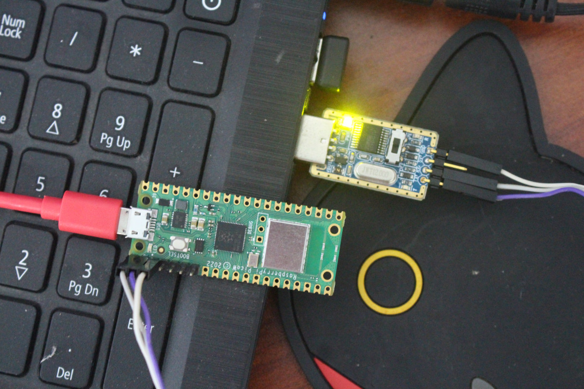
Get started with WiFi on Raspberry Pi Pico W board with MicroPython and C. Learn how to set an access point, run iperf, control an LED, etc.
 dusk flower
Uh... Correct me if I'm wrong.
When I enable SPI, only bank 0 goes up by default, right?
Can I still use the pins assigned to bank 1 as normal gpio?
dusk flower

Ok, dropped the neopixel in favour of a LEDShim
(I2C driven, no level shifters or separated PSU, easy to stash in the RFID reader casing...)
If I don't add anything else, this should be the end of it, and yet I still have pin availability for stuff like a fan!
If I didn't occupy any reserved pin where I shouldn't, this layout would also be useful for routing the board with minimal ratnesting
derrrrp, this should've gone in *hw-design 😐
 light horizon
Hi all, does anyone know where I can find a GPIO pinout for Raspberry Pi 2011.12 (I am not sure which model this is, this is all that it is written on the board)? I want to replace it in an installation with a RPi 4.
 dusk grotto
Is this the board?
 light horizon
yes, that's the one @dusk grotto
 light horizon
incredible, thank you so much, @dusk grotto
 zinc jackal
I'm pretty sure I still have my 512MB Model B around somewhere
dusk grotto
light horizon
incredible, thank you so much, <@529161420609421312>
Np I'm just trying to help out
light horizon
zinc jackal
I'm pretty sure I still have my 512MB Model B around somewhere
they seem to be pretty resilient little computers, im super impressed that the one i am being paid to replace is still operational
dusk grotto
zinc jackal
I'm pretty sure I still have my 512MB Model B around somewhere
I got one like 2 years ago when I bought a box of arduino's and bread boards and other stuff
zinc jackal
I know mine still works, I just have to find it. 😅
But then, I'm trying to get a 3D printed case for my Zero 2 W.
...which would be a darn sight easier if I had a 3D printer.
dusk flower
zinc jackal
I'm pretty sure I still have my 512MB Model B around somewhere
I do have a Pi1B right here in its pink case.
it was used as a print server until recently, and worked way better than any compact IP print spool out there XD
dusk flower
zinc jackal
...which would be a darn sight easier if I had a 3D printer.
welcome to the club, I'm looking for either a CNC mill or a laser engraver (gotta engrave plexy) that wont cost an eye and a kidney, with decent specs
I think I saw one from creality at a nice price point
zinc jackal
Well.... You could make an adaptable machine to do all three?
 rain rain
Hi adafruit,
Im developing some AWS IoT modules for a raspberry pi (actually for several) and im using the sensors of BME280, BN055 and INA260.
Each one of them im having some trouble because randomly gives spikes of 1 value (im reading and sending the value to grafana each 10 secs (aprox))
For example the temp is constant around 28-32 C degrees, but suddendly spikes to 1200 C degrees or 40 C degrees, is a bit random.
I have developed a few functions to have a natural progresion to that value (if its a true value) but the thing is I do have so many variables and want to find a proper solution.
In the docs I could not find anything usefull, and the calibration does not help.
I have tried other new sensor (of the same model) but the spikes dont leave.
Thank you.
PS: Im not sure if I should post in circuitpython, adafruit, or raspberry pi, so I will post in the 3 and if needed deleted after.

 chilly obsidian
Hi! I recently purchased an MPR121 Capacitative Touch hat from Adafruit. It’s all soldered and currently on my Raspberry PI, but I’ve run into a recent issue. I’m using the pygame mixer script. I connect all the alligator clips to the objects before power on, but when I run it — all of the touch pads are triggering at once and it sounds quite chaotic. When I unplug the clips, the touch pad work as normal after power on. It’s currently ruining my life and I have a art installation opening on Friday. I’m an absolute novice at coding, but wondering if the continue and/or break line of code (within ‘While true’ block) is throwing it off? I’ve been switching the statements and getting varied results. Any support would be helpful!
 midnight sage
okay I wish to know how I can program a 16 X 2 LCD Screen to show Raspberry Pi's status like CPU Temp to Fan Speed (if installed) and cpu and memory usage - can this work? I have the NEW Amiga 1200 case that supports the 16 x 2 LCD Screen
I would love to put as much status on it within a 16 x 2 LCD Screen
dusk flower
midnight sage
okay I wish to know how I can program a 16 X 2 LCD Screen to show Raspberry Pi's...
Lcdproc is your friend, along with an HD4870 screen (16*2)
midnight sage
needs to fit inside the NEW Amiga 1200 case's LCD location
dusk flower
as long the controller is supported ¯\_(ツ)_/¯
midnight sage
Here's what I've thought of showing
cpu temp then activity
memory useage then GPU if it's still within' 16 characters
 dapper steppe
So, does anyone know what caused the raspberry pi shortage? Is it just a whole bunch of people buying them, or an actual supply chain problem?
midnight sage
according to the true reason is the Auto industry and the virus
 civic rune
What's the best way to find circuitpython libraries and install them on the pi with blinka? For that matter how can I check if blinka is already installed?
steady rose
import board
 ruby night
civic rune
What's the best way to find circuitpython libraries and install them on the pi w...
ruby night
civic rune
What's the best way to find circuitpython libraries and install them on the pi w...
You can browse the libraries here https://docs.circuitpython.org/projects/bundle/en/latest/drivers.html each one has instructions for installing via pip3
to check for blinka you can pip3 list to see if it is installed.
steady rose
there's a simple blinka test here:
https://learn.adafruit.com/circuitpython-on-raspberrypi-linux/installing-circuitpython-on-raspberry-pi#blinka-test-3030038
tired marsh
which is generally adding -circuitpython- in the middle on the name
civic rune
thanks folks
steady rose
pip list would work also, to just check if its installed
the blinka test script checks some other things, like if I2C and SPI are enabled
civic rune
oh I forgot about init'ing i2c and spi
would the blinka installation take longer if I have poor internet service?
civic rune
it currently just says "upgrading packages" and has for about 15 minutes
 ripe pike
I'm looking for help searching for a solution to power multiple Pis off a single PSU. Ex: a "hub"/hardware that has multiple USB ports, each able to provide ~5V 2.5A. My problem is - what do I search for? what are these solutions called? I can imagine other ppl are powering multiple Pis without having a single PSU per Pi - how are they doing it?
civic rune
I think the process is hung. It's been over an hour since it got to the Upgrading Packages section. How can I interrupt it?
there we go. CTRLC
 still notch
I am trying to build a "point and shoot" camera w/ a Rasp Pi Zero 2 W , a Rasp Pi camera, and the Adafruit Mini PiTFT - 135x240 Color TFT.
I learned:
- camera.preview() "hard wires" previews to the HDMI port
- there might be a way to get this to work using pygame instead of pyCamera.
So I am hopeful about using pygame. However, I follow the examples, adding
os.putenv('SDL_FBDEV', '/dev/fb1')
However, images go to a window on my HDMI display. I am looking for help on how to debug this and get it working.
Thank you very much.
civic rune
Is there a map somewhere of the pi pinout to the results of dir(board)?
 rotund pivot
(or from [Circuit]Python: https://gist.github.com/anecdata/1c345cb2d137776d76b97a5d5678dc97)
civic rune
that works thanks!
Any idea how to kill a process when the COMMAND name isn't obviously appearing in ps aux?
tired marsh
civic rune
Is there a map somewhere of the pi pinout to the results of `dir(board)`?
it's just the GPIO numbers, isn't it ? https://pinout.xyz/#
midnight sage
Aren't the Pi 4 and Pi 3 B+ same size? if they are I'm gonna make a universal pi 4/3b+ mounts for my Amiga 1200 case project
fickle rose
they are the same size but they have different port arrangements so that's something to watch out for
midnight sage
As long it's the same size and same hole placements I'm good - I can make an universal Amiga 1200 case Pi Mount for a 4 or 3 pi
midnight sage
Can this work with the pi? - https://www.adafruit.com/product/292 I may use it to pull up the Pi's Status like some theses on the LCD - wanna have this display and delay for about 10 secs before switching to the next Pi Status


LCD backpacks reduce the number of pins needed to connect to an LCD. LCDs are a fun and easy way to have your microcontroller project talk back to you. Character LCDs are common, and easy to ...
tired marsh
midnight sage
Can this work with the pi? - https://www.adafruit.com/product/292 I may use it t...
yep, link to the guide at the bottom of the page
midnight sage
if only it worked with OLEDs though - the LCD is gonna be mounted inside my A1200.net Amiga 1200 case where the display cutout is located
tired marsh
dunno, there are I2C monochrome oled breakouts, usually small displays
midnight sage
I might get those female headers and solder them onto the LCD so I can mount the LCD to the Amiga case and put it onto the header - should I use I2c or SPI to pull up the Pi's status like those generated images displaying them?
tired marsh
🤷 whichever is more convenient, I2C uses less pins
midnight sage
I2c it is working with Pi's Status will be my thing to show on the display
midnight sage
once I have it I'm gonna work it until I'm happy with the code from piguy's code or adafruit's own code then run it on startup
civic rune
how can I get the current working directory (in python at least) to stay /home/username/Desktop?
between reboots
tired marsh
making the current working directory a certain directory when you run a script ?
oh, start your default shell in a different directory ?
civic rune
yeah the second thing
tired marsh
what shell is it ?
civic rune
I'm using thonny since it came with the device and getting anything on a pi 3 is a pain
anything new
tired marsh
so not the default shell, you mean start python in a certain directory in Thonny ?
tired marsh
well, don't know if that's an option
civic rune
no worries
 fierce spire
ive used ping on my raspberry pi zero w and its going for like 5 minutes its at 350 times now when will it stop?
opaque wagon
It never stops
Use control+c to stop ut
(that should stop almost any cli program)
dusk flower
Ok, if I'm understanding the docs right, EEPROM on hats serves to set the state of the pins on boot, right?
ruby night
fierce spire
ive used ping on my raspberry pi zero w and its going for like 5 minutes its at ...
I control C does not work -- close the window that is running ping
dusk flower
So I use input for a button, output for a led, and ALT0-5 for the function assigned to that pin on that alt level (i.e. SPI pin)?
 snow timber
fierce spire
ive used ping on my raspberry pi zero w and its going for like 5 minutes its at ...
snow timber
fierce spire
ive used ping on my raspberry pi zero w and its going for like 5 minutes its at ...
Might want to use ping -c 4 x.x.x.x which will ping 4 times in this example and stop
civic rune
does anyone know how to tell what services are running at a given time on your pi?
 vocal lava
civic rune
does anyone know how to tell what services are running at a given time on your p...
vocal lava
civic rune
does anyone know how to tell what services are running at a given time on your p...
ps -aux
That's prcoesses. You can try top too
civic rune
thx
tired marsh
service --status-all
ok my service is running, but the code (which I checked works fine, it's just blinking an LED) is NOT running.
here's my service, it's patterned off of one that is working.
[Unit]
Description=test service

[Service]
Type=oneshot
ExecStart=/home/pi/Desktop/test2.py
StandardOutput=null

[Install]
WantedBy=multi-user.target
I feel like this should just be working. I also ran sudo systemctl enable testservice.service where testservice.service is the name of my service. Anyone have any hot tips?
civic rune
just sudo systemctl start?
oh
yeah
I did
I checked and it's enabled
I checked using systemctl list-unit-files
vocal lava
What does systemctl status servicename say?
civic rune
one moment
ah failed
"failed at step EXEC spawning /home/pi/Desktop/test2.py: Permission denied"
civic rune
ok the code is still not running, let me check status again
I think rebooting is better because I'm trying to test that it runs on boot
ok now it's failing with "exec format error"
let me check my syntax
seems fine
vocal lava
Oh, that won't work
you need to call python to run that like /usr/lib/python3 yourscript.py
civic rune
huh
vocal lava
This line: ExecStart=/home/pi/Desktop/test2.py
civic rune
my older service works on another pi just fine and is bit for bit identical to what's above
except it's not test2.py it's the name of other code
vocal lava
Right, I bet it's an executable of some kind
civic rune
ohh so I need to make it an executable?
vocal lava
Here's an example of mine, but I use a virtual env: ExecStart=/home/prcutler/workspace/pi-dial/.venv/bin/python /home/prcutler/workspace/pi-dial/pidial.py
civic rune
I remember doing that now! This is completely an argument for writing things down
vocal lava
See how I'm calling python to run the script?
civic rune
ack gotta edit this in sudoed nano
civic rune
vocal lava
sudo systemctl restart servicename
I got a warning that the unit file had changed on disk and to use daemon-reload and also got the same failure error message (no new code). Do I need to do the reload thing?
vocal lava
If you edited the file, pretty sure, it's been a while since I've touched systemd
If it told you to, I would
systemd is one of those things that once I've got it working I never want to touch it again. 🙂
civic rune
Oh I can relate!
vocal lava
I thought you might!
civic rune
vocal lava
I thought you might!
hey it's working now!! Thank you! How do I sever the service?
or stop it or whatever. I just wanted to test that I could get it working
civic rune
perfect
I'll have to time it such that my light isn't on when i stop it hehe
ok time to write this down somewhere
and if I want to re-enable the service? just enable?
vocal lava
If you enabled it, it will autostart on boot
civic rune
oh so even though I told it to stop?
vocal lava
correct, that's what enable does.
start, stop and restart are the ones you'll usually run when updating it
civic rune
oh sorry if I stop it, it will still run on boot because I enabled it?
is that right?
vocal lava
Correct
civic rune
so how can I stop it forever? Disable?
vocal lava
Yup
vocal lava
If it's running when you disable it, you still need to stop it. But it will not start after rebooting
civic rune
that makes sense. OK
opaque wagon
Systemd is great, but hopefully u will never have to touch it again lol
civic rune
I'm writing it up now so it's painless in the future!
civic rune
Does anyone know what "language" a .service file is written in? I'm using a code formatting plugin for docs and it takes a language input
vocal lava
I don't think there is a code language associated with the systemd files
civic rune
really?
civic rune
Hmm
I notice in NANO, that anything inside [] blocks is highlighted. What does that signify?
vocal lava
Not sure, my nano didn't do that when I opened up one just now
tired marsh
does it have ini file or something ?
midnight sage
Can the py autostart Py Scripts? I need to have a script autostart on boot to desktop
vocal lava
midnight sage
Can the py autostart Py Scripts? I need to have a script autostart on boot to de...
Yes, it's possible by creating a systemd service
midnight sage
I wonder how I can do that once I my LCD status is finished
civic rune
midnight sage
I wonder how I can do that once I my LCD status is finished
ping me when you need help, I am happy to provide guidance.
When you point ExecStart to python first and then to a file, what exactly are you doing? Are you saying "here's my thing that does executions and then here's my file to execute with it"?
 vestal root
Do you think I would be possible to use a raspberry pi 4 as a keyboard?
civic rune
absolutely
but
a waste of resources for the most part
A pi 4 is quite powerful, you don't need anywhere near that power to run a keyboard
vestal root
Eeeeh, depends, I want to create a thing that I could plug into my server, it would login and run somes commands while hosting a web page so I can know what's its doing and when it's done
I would have bought a pi zero w if I wasn't out of stock everywhere
I have at home a pi4
Kinda like a bad USB but to update /upgrade my server
midnight sage
civic rune
When you point ExecStart to python first and then to a file, what exactly are yo...
what I'm doing is simple I'm gonna write simple code to the LCD to pull up the Pi's status like CPU Temp and Activity and it switches back and forth on my cpu usage and temp - its will start up on boot so I don't need to run it manually
dusk flower
midnight sage
what I'm doing is simple I'm gonna write simple code to the LCD to pull up the P...

GitHub
Python module to drive PCD8544, HT1621, ST7735, ST7567 and UC1701X-based LCDs - GitHub - rm-hull/luma.lcd: Python module to drive PCD8544, HT1621, ST7735, ST7567 and UC1701X-based LCDs

GitHub
Companion repo for running examples against the luma.oled, luma.lcd, luma.led_matrix and luma.emulator display drivers. - GitHub - rm-hull/luma.examples: Companion repo for running examples against...
midnight sage
it's a 16x2 character LCD I'm gonna use which the Amiga 1200 has for the HxC FLoppy Drive Emulator
dusk flower
There's one that seems to fit the bill
This seems to do what you need, try it out
https://github.com/rm-hull/luma.examples/blob/master/examples/sys_info.py
GitHub
Companion repo for running examples against the luma.oled, luma.lcd, luma.led_matrix and luma.emulator display drivers. - luma.examples/sys_info.py at master · rm-hull/luma.examples
You need to install the psutil module
midnight sage
Gonna use Adafruit's LCD library since I'll be getting their LCD Backpack then make the LCD do this and waits to change the the other CPU Status
 dusk flower
Psutils module, can fetch temps as well
vocal lava
dusk flower
Psutils module, can fetch temps as well
https://psutil.readthedocs.io/en/latest...
Thanks for sharing that, that will be useful for a friend of mine
midnight sage
would it work with their Backpack driver?
dusk flower
Of course, it's just a data fetcher, what you do with it is your problem
Btw, that backpack is a hd4870, the most generic controller ever, and luma.lcd will do the job gracefully, go at least try the demo I linked
midnight sage
it will come in handy once I have it since it's a 16x2 Driver I'm wondering if it works with one of Sparkfun's LCDs they make it's basically the same LCD but their branding
dusk flower
Same controller, same functionally
vestal root
Does anyone have a guide or something to use a pi 4 as a hid device?
dusk flower
I think Zero can do it, don't know if 4 has the required boot mode for doing so
vestal root
Yeah but almost 100€ for a zero is e x p e n s i v e
Maybe the boot mode or something can be changed?
dusk flower
Look at the documentation on Pi site
dusk flower
vestal root
Yeah but almost 100€ for a zero is ***e x p e n s i v e***
Maybe the boot mode o...
All cards are currently made of unobtanium
vestal root
Sad
dusk flower
Yep
vestal root
Guess I'll buy a Pico tomorrow and a zero when the price will be lower than my grades 
dusk flower
I'd like to use a 4 for this project of mine, "stuck" with a 3b+ and a blind 2b
vestal root
I have a pi 4, it was used until fews days ago as a temporary router, now I'm looking onto a new user for it
dusk flower
I also have two 0s, but I need them for another project on hold 🤣
Need to find a way to make a conf webpage for it
tired marsh
FYI the 4 does support OTG on the USBC port
 broken bay
Hi im a beginner with circuitpython, so I played a bit with it on Thonny but now I wanna try to get on a bigger project so I'll be using pycharm. I followed this tutorial : https://learn.adafruit.com/welcome-to-circuitpython/pycharm-and-circuitpython ; it worked perfectly until I ran the code and I got this error :
  File "D:\code.py", line 2, in <module>
    import board
  File "C:\Users\||nope||\AppData\Roaming\Python\Python39\site-packages\board.py", line 279, in <module>
    raise NotImplementedError(
NotImplementedError: Adafruit-PlatformDetect version 3.27.0 was unable to identify the board and/or microcontroller running the Windows platform. Please be sure you have the latest packages running: 'pip3 install --upgrade adafruit-blinka adafruit-platformdetect' ```
so apparently pycharm is not detecting my board, thonny detects it and run the code perfectly and the adafruit-platformdetect is updated to its latest version so I dont really understand lmao.
I also saw this post https://forums.adafruit.com/viewtopic.php?f=24&t=188542 but I didn't understood that much and idk if it's relevant so I'll need some help I guess 🙃 (sry for spelling mistakes and stuff im french)
Adafruit Learning System
New to CircuitPython? This is the place to start.
tired marsh
broken bay
Hi im a beginner with circuitpython, so I played a bit with it on Thonny but now...
that's python running on your computer not on the board
what board are you using ?
to get the REPL of the board, you need to connect to its serial port using a serial tool, like tio https://learn.adafruit.com/welcome-to-circuitpython/pycharm-and-circuitpython#serial-console-in-the-terminal-pane-3105096
broken bay
tired marsh
what board are you using ?
It's a raspberry pi pico
and im on windows btw
tired marsh
Thony detects the board and shows the repl and lets you execute a file directly on the board with the run button, with pycharm you have to connect to the board manually to see the output of code.py
broken bay
ooh ok ty
broken bay
as tio is not available on windows what software should I use ?
tired marsh
ah, right on windows I don't know, Tera Term, Putty ?
broken bay
k im downloading Tera Term rn
should I go for standard or full installation ?
ok I went for the full one my pc is not gonna die for 4 MB
okayy it's not working
well I'll just go for vs code this time
anyway thank you for your help the explanations were really good
 bitter fiber
@broken bay Actually, you can install tio on windows via msys2 or wsl/ubuntu.
broken bay
well ok im gonna give it a try
civic rune
midnight sage
what I'm doing is simple I'm gonna write simple code to the LCD to pull up the P...
what language will the code be in?
midnight sage
civic rune
what language will the code be in?
simple python to drive the LCD with adafruit's LCD Python or something else to pull the status up for the Pi's CPU Temp and Activity
civic rune
ok check out this guide when you're ready
The process is a little different for python files but this is the background you need
 tame notch
Hello everyone. İ want to install latest version blinka to my jetson Nano. But i can install just 6.15.0 version l. Ubuntu list version from 1 to 6.15 but there is not 7 and abone
dusk flower
Use pip3
 hushed vortex
@tame notch Make sure you have Python 3.7 installed and set as the default. If you're not sure how, you can use this: https://learn.adafruit.com/circuitpython-libraries-on-linux-and-the-nvidia-jetson-nano/initial-setup#install-python-3-dot-7-and-make-default-3114929

Adafruit Learning System
Make hardware and interface with sensors super easy using CircuitPython
 stone pecan
I am trying to connect to a second PCA9685 with my RPI and python, however; i can not figure out how to call the second chip in the code. Can someone point me to some example code on how to control PCA9685 with circuit python?? https://github.com/adafruit/Adafruit_CircuitPython_Motor/blob/main/examples/motor_pca9685_servo_sweep.py
GitHub
Helpers for controlling PWM based motors and servos - Adafruit_CircuitPython_Motor/motor_pca9685_servo_sweep.py at main · adafruit/Adafruit_CircuitPython_Motor
i have connected both chips, and assigned the address etc. Im not sure how to call the second chip in the code.
 upper oracle
im having the same issue ^
upper oracle
do you have to use circuit python for this?
steady rose
pca1 = PCA9685(i2c)  # use default 0x40
pca2 = PCA9685(i2c, address=0x41) # specify 0x41
okay thanks
steady rose
the library is circuitpython, but can be used with regular python on an RPI using Blinka
 scarlet latch
Hey guys, I am looking for to use some industrial sensors that are 4..20ma and land them into my raspberry pi. Have you guys done something like this? Any recomendations for an interface board?
upper oracle
do i have to create another ic2 for this in the code?
steady rose
nope. that gets shared.
upper oracle
gotcha
 versed fjord
could some one point me in the right direction ... I got the adafruit is2 audio bonnet to work with my pi Zero W .... I want it to work with omxplayer (command line audio), but after the initial install (where you test the sounds in left speaker and right) no audio plays
would this be a question for Audio ?
vocal lava
This channel should be fine
vocal lava
versed fjord
could some one point me in the right direction ... I got the adafruit is2 audio ...
Did you follow the learn guide and install the script? https://learn.adafruit.com/adafruit-i2s-audio-bonnet-for-raspberry-pi/raspberry-pi-usage
versed fjord
yes sir I did
everything but the detail install
that was my next step
oh I did not try the /dev/zero playback option
tame notch
Hello again i installed blinka as your advise to my jetson Nano. But getting error like this at finally


 queen sandal
Is it possible to run an Led straight from a 3.3 GPIO pin or should i use something in between?
umbral sable
queen sandal
Is it possible to run an Led straight from a 3.3 GPIO pin or should i use someth...
You'll want a current-limiting resistor in most cases, which will protect both the GPIO and the LED and let you choose the right brightness too.
queen sandal
I need to run 16 individual leds at different times. will that have an affect on the pico or should i use a driver
umbral sable
There's typically a datasheet spec for the total current that all the GPIOs in a MCU can source together. You should be fine if the LEDs are (just as a ballpark) less than 5mA each, but might run into Pico limitations if they are more like 20mA.
tame notch
Hello again i installed blinka as your advise to my jetson Nano. But getting error like this at finally

 hushed vortex
tame notch
Hello again i installed blinka as your advise to my jetson Nano. But getting er...
hushed vortex
tame notch
Hello again i installed blinka as your advise to my jetson Nano. But getting er...
Hi, it looks like Setuptools is missing. Make sure you have everything updated by following this section in the same guide: https://learn.adafruit.com/circuitpython-libraries-on-linux-and-the-nvidia-jetson-nano/initial-setup#update-your-board-and-python-3039592
Adafruit Learning System
Make hardware and interface with sensors super easy using CircuitPython
tame notch
hushed vortex
Hi, it looks like Setuptools is missing. Make sure you have everything updated b...
Thanks all of things i fixed help of another web page with writing on Google last error code
tame notch
hushed vortex
Hi, it looks like Setuptools is missing. Make sure you have everything updated b...
you are a benevolent angel :D
 lament swan
Hello, I am trying to install the new picamera2 library (https://github.com/raspberrypi/picamera2) based on the new libcamera stack in Rasbian Bullseye. I am running into issues when I run pip install picamera2 at the point where it is trying to install PyQt5. I've looked at various posts on the internet and they all say "make sure qmake is on PATH" and I don't know how to "make sure" that it's on PATH. Like how do I know I have qmake (where do I get it?), where is my PATH (I want this in a virtual environment so the obvious $HOME/bin" does not hold here. And once I figure out my PATH, how do I make sure qmake is on it? Any leads?
Thank you in advance
GitHub
New libcamera based python library. Contribute to raspberrypi/picamera2 development by creating an account on GitHub.
 agile spindle
Anyone know if it would be possible to create a program which uses the Pis sound card to detect if the duration of a tone played and transcribe the duration of the tone played in seconds? I need to be able to detect the loudest sound (the tone) amongst background noise
And if so does anyone have resources relating to the topic
umbral sable
You'll probably want to investigate FFT (Fast Fourier Transform), which is how you would pull out the frequency components of an audio signal.
hard pike
FFT + Windowing techniques are very useful in audio processing:)
vocal lava
lament swan
Hello, I am trying to install the new picamera2 library (https://github.com/rasp...
To check if you have qmake, do a sudo apt-get install qmake - if it's installed it will yell at you, if it's not it will install it. Start there
agile spindle
umbral sable
You'll probably want to investigate FFT (Fast Fourier Transform), which is how y...
Ah, this should give me a good start with my morse code translator
umbral sable
And if you know the specific frequency tone you're looking for, you can be more efficient, too, with a bandpass or Goertzel filter.
agile spindle
umbral sable
And if you know the specific frequency tone you're looking for, you can be more ...
Yeah thats not going to happen, trying to translate random stuff i find on a radio, not every channel is the same and i think some are even a slightly different frequency
lament swan
vocal lava
To check if you have qmake, do a sudo apt-get install qmake - if it's installed ...
Thanks for entertaining the question. I do/did have qmake. It’s in my ‘/usr/bin’ folder. I also had pyqt5 but in the root user. It was installed using “sudo apt-get install python3-pyqt5”. I just wasn’t able to get it inside my virtual environment. My shoddy workaround that was to enable my virtual environment to be able to pull from system-site-packages. After that picamera2 was a breeze. I know that it’s kind of against what a virtual environment does, but that was the only way I was able to get pyqt5 to allow picamera2 to install. If anybody finds an actual way to install pyqt5 inside Python virtual environment, please remember to publish it somewhere for folks like me 🥲
My problem and my solution to it is posted at:
https://forums.raspberrypi.com/viewtopic.php?p=2027822&hilit=Picamera2+fail#p2027822
vocal lava
Glad to hear you got it working. 🙂
versed fjord
i was hoping some one could help me with omxplayer install on my pizerow with is2 audio bonet .... I am using the guide here "https://github.com/popcornmix/omxplayer" and its the " make -j$(nproc) " command that I get an error at
steady rose
what's the error?
versed fjord
steady rose
what's the error?
bash gen_version.sh > version.h
g++ -pipe -mfloat-abi=hard -mcpu=arm1176jzf-s -fomit-frame-pointer -mabi=aapcs-linux -mtune=arm1176jzf-s -mfpu=vfp -Wno-psabi -g -std=c++0x -D__STDC_CONSTANT_MACROS -D__STDC_LIMIT_MACROS -DTARGET_POSIX -DTARGET_LINUX -fPIC -DPIC -D_REENTRANT -D_LARGEFILE64_SOURCE -D_FILE_OFFSET_BITS=64 -DHAVE_CMAKE_CONFIG -D__VIDEOCORE4__ -U_FORTIFY_SOURCE -Wall -DHAVE_OMXLIB -DUSE_EXTERNAL_FFMPEG -DHAVE_LIBAVCODEC_AVCODEC_H -DHAVE_LIBAVUTIL_OPT_H -DHAVE_LIBAVUTIL_MEM_H -DHAVE_LIBAVUTIL_AVUTIL_H -DHAVE_LIBAVFORMAT_AVFORMAT_H -DHAVE_LIBAVFILTER_AVFILTER_H -DHAVE_LIBSWRESAMPLE_SWRESAMPLE_H -DOMX -DOMX_SKIP64BIT -ftree-vectorize -DUSE_EXTERNAL_OMX -DTARGET_RASPBERRY_PI -DUSE_EXTERNAL_LIBBCM_HOST -I./ -Ilinux -Iffmpeg_compiled/usr/local/include/ -I /usr/include/dbus-1.0 -I /usr/lib/arm-linux-gnueabihf/dbus-1.0/include -I/usr/include/freetype2 -isystem/opt/vc/include -isystem/opt/vc/include/interface/vcos/pthreads -c linux/OMXAlsa.cpp -o linux/OMXAlsa.o -Wno-deprecated-declarations
linux/OMXAlsa.cpp:22:10: fatal error: IL/OMX_Core.h: No such file or directory
22 | #include <IL/OMX_Core.h>
| ^~~~~~~~~~~~~~~
compilation terminated.
make: *** [Makefile:49: linux/OMXAlsa.o] Error 1
steady rose
did you run ./prepare-native-raspbian.sh?
versed fjord
yes
pi@raspberrypi:~/mygitstuff/omxplayer $ sudo ./prepare-native-raspbian.sh
Modifying for native build on Debian
Checking dpkg database for missing packages
................
All dependencies met
Checking for OMX development headers
...
All dependencies met
Checking amount of RAM in system
You should have enough RAM available to successfully compile and run omxplayer.
sorry new to discord ... i wanted to past that as code
steady rose
looks like that repo has not been touch in years
guessing things have changed with latest OS releases
in terms of specific locations for the dependencies
(there's info in #welcome about how to do code markup)
versed fjord
yeah omxplayer is being depricated for VLC ...but I run a simple program(also from git) that does a call to prayer 5 times a day and it uses omxplayer ...it works on the old pi model b just fine but now trying to get it to work on my pizero w
versed fjord
humm
this is what I am trying to impliment on my pizeroW https://github.com/achaudhry/adhan

GitHub
Raspberry Pi Adhan Clock . Contribute to achaudhry/adhan development by creating an account on GitHub.
versed fjord
i think I know what i will do
go to legacy version of raspberry pi ( buster instead of bullseye)
that way things should work better i think
 misty crypt
Is this an appropriate channel to ask pi pico questions (PIO in particular), or would there be a better channel? (Where's help-with-help? 😛 ) Thanks.
vocal lava
misty crypt
Is this an appropriate channel to ask pi pico questions (PIO in particular), or ...
Ask away. Someone might suggest another channel, but not sure myself
opaque wagon
there used to be #help-with-rp2040-pio, but that was archived
use #help-with-arduino for arduino questions, or #help-with-circuitpython for circuitpython questions
 faint sparrow
@misty crypt There's a Raspberry Pi Pico discord.
https://www.raspberrypi.com/news/multilingual-blink-for-raspberry-pi-pico/ scan that article. ;)
misty crypt
Thanks everyone.
 worn drift
i've made a little raspberry pi + solar powered rover and it has a pi cam. is there a way to connect a second pi cam to it, so that i can have 1 camera facing "forwards" and the second facing "backwards"?
ruby night
worn drift
i've made a little raspberry pi + solar powered rover and it has a pi cam. is th...
You can use a "USB" camera for the second camera.
worn drift
would that work with raspistill ?
ruby night
Probably not -- this may help https://www.arducam.com/docs/cameras-for-raspberry-pi/multi-camera-adapter-board/introduction/ there are adapters... I've had no experience with them.
worn drift
i've never used a raspberry pi compute module, does that attach to my existing raspberry pi? or replace it?
ruby night
It connects to a compute module IO board. It is a Pi4 by itself. https://www.adafruit.com/product/4787

Exposing every interface from Raspberry Pi Compute Module 4, the Compute Module 4 IO Board provides a development platform and reference base-board design for the most powerful Compute ...
this may alos be of interes -- using Open CV with a pi camera and a USB camera https://pyimagesearch.com/2016/01/18/multiple-cameras-with-the-raspberry-pi-and-opencv/
worn drift
if i'm using raspbian currently, can i just use my same raspbian image on a pi compute module?
worn drift
ruby night
this may alos be of interes -- using Open CV with a pi camera and a USB camera <...
yep that's exactly the route i'm going and i've also done a PoC with that, with real time object detection in stream
ruby night
I have not done a lot with raspian on the compute modules, but I think it uses the same images as any Pi.
worn drift
i made a little solar powered, pi powered rover and a little website where people can see what it's doing and send commands to move it (basically for my friends, lol). but while working on it, you can issue a "move backwards" command but you can't really see where you're going yet... 🙂 trying to solve for that problem
ruby night
I use RPI Web Cam inerface on my Pi robot https://elinux.org/RPi-Cam-Web-Interface
It provides a webserver to look at the videso.
I then us a separate python program to "drive"
worn drift
does the webserver run on the pi? i'm trying to stream it publicly
ruby night
yes
I use it for several "web cam" applications.
It usese the "legacy" camera (raspivid) but runs on bullseye -- pretty simple install ```git clone https://github.com/silvanmelchior/RPi_Cam_Web_Interface.git
cd RPi_Cam_Web_Interface
./install.sh
ah i see, this camera IO module connects to a pi compute module. dang the pi compute modules look to be all sold out currently
ruby night
all pi's are tough to get these days. The above webserver runs on a Pi zero w or pi zero 2
or any other pi with wifi.
worn drift
maybe i'm confused - does https://www.adafruit.com/product/4787 only connect to / work with a https://www.adafruit.com/product/4782 ? or can you connect to it any pi zero, pi3/4, etc?
Exposing every interface from Raspberry Pi Compute Module 4, the Compute Module 4 IO Board provides a development platform and reference base-board design for the most powerful Compute ...

The Raspberry Pi Compute Module 4 is based on the Raspberry Pi 4 Model B, but in a smaller form factor - perfect for embedding into products or projects without the bulk of a classic ...
ruby night
it only connects to a compute module
the arducam adapter connects to a regular pi., I think..
worn drift
cool, thanks! i'm real interested in that 2 camera module IO board and copute board.. i'll add that to my wishlist for when they're back in stock. til then i'll look for a cheap usb camera 🙂
ruby night
Good luck!
worn drift
kind of related, do you happen to know what gps options are for a pi? i've seen the hats - but i already have a hat and it's unclear how i can add more hats on top of hats.. that don't have the plugs/pins
ruby night
There are USB versions https://www.adafruit.com/product/4279
worn drift
wonderful thank you, i appreciate it 🙂 i think that will do the trick. i'm trying to geo-fence my rover so people can't drive it in to the pond 😅
ruby night
Good plan!
 edgy oar
ruby night
I use it for several "web cam" applications.
edgy oar
ruby night
I use it for several "web cam" applications.
Didn't know about that. It's way more stable than 'motion'; thanks!
ruby night
edgy oar
Didn't know about that. It's way more stable than 'motion'; thanks!
Glad it is useful. It does use motion as its lower level.
edgy oar
Yeah,; but using just motion, as I was before, was crushing the Pi. Load avg was ~4 and it would eventually crash after a day or two. Now load is <1
seems fine!
midnight sage
Could it be possible to use a SSD for the Pi 3B+ instead of SD Card?
hard pike
Might be hard
but maybe someone has made a sata to sd bridge
this might be an idea: https://www.aliexpress.com/item/3256802650120107.html

aliexpress.com
Smarter Shopping, Better Living! Aliexpress.com
 sonic scroll
On what board should is be possible to make a platform like adafruit io?
 somber yacht
Hi guys, I have a question about powering the rpi 4. I have the buck converted I linked below. If I take the usb out and plug that into the pi I have no issues. If I take the +/- pins and connect them to pin 4 and 6 on the header the pi seems to power up but never connects to wifi and when I plug it in via ethernet both lights on the jack light up but the activity light does not blink just stays constant. If I take the +/- out and plug that into the usb port I have no issues again.
Anyone know why the network wont connect when I power the pi via pin 4 and 6?
https://www.amazon.com/dp/B0989DKYWN?psc=1&ref=ppx_yo2ov_dt_b_product_details

Buck Converter Module 12v to 5v 5A USB Voltage Regulator DC 9V-36V Step Down to USB 5V Transformer Dual Output Voltage Regulator Board for Phone Fast Charging(2 PCS)
 half nexus
Hi there, dumb question, it's either hit or miss.
Can I run micropython code designed for RPI pico on a normal RPI (1 B+)
opaque wagon
no, you will have to modify the code for regular python
 lapis stratus
Following the guide for getting the WS2801 up and running I'm in trouble.
D6 for serial clock and D5 for serial data - nothing when running the sample code 😓 the first LED changes color when I touch the green serial jumper cable though 😅

Okay nevermind, the t was not pushed into all the way into the GPIO of the pi

 bronze dock
crosspost from the help-with-projects channel, since its a raspi and I don't know which chan is more appropriate. apologies if this is a no-no:
heya! still working on my space station/space object pointer, been thru a few different revisions, and just wanted to sanity-check my next bit of code before I start writing it out. make sure im not missing some idea or library that will make this part simpler:
I have a servo connected thru a slip-ring, on top of a stepper, so it can spin forever without getting wires tangled. the stepper will spin 360 to point in any direction needed, and the servo can point from DOWN to UP, to cover any elevation needed.
I get my space station location info from the internet, using JPL's Horizons system, but I can't be %100 connected, so I plan on downloading info for the next 24hrs, perhaps 1min resolution, upon startup. that would be 24*60 = 1440 lines in my table. and then save that to a file on my raspi...
each line in the table will include TIME (24h:MM:SS), AZIMITH (0.00 - 359.99), and ELEV (0.00 - 179.99)
my thought for each update/loop is to: find the appropriate line in my table based on current time (probably remembering my last location so I dont have to run thru the whole table each loop). if the value has changed more than 1 step, then take a step.
am i overcomplicating or brute forcing this? am I missing some tool or library that could make this easier? or does this seem like a reasonable solution?
midnight sage
here's a silly question can the Pi have a "bootup" sound that plays on power up?
civic rune
Yes
You can do it in a few languages
But it probably won't be right on bootup like you're thinking?
 turbid rivet
midnight sage
here's a silly question can the Pi have a "bootup" sound that plays on power up?
turbid rivet
midnight sage
here's a silly question can the Pi have a "bootup" sound that plays on power up?
Have you tried any of the solutions here? The post is a bit dated but it should still work in theory. https://raspberrypi.stackexchange.com/questions/24723/create-startup-sound

Raspberry Pi Stack Exchange
I know that this question has already been answered, but the method described here
is actually not working for me... o.O
I read in some other forums that a different formatting is required, but I d...
dusk flower
midnight sage
here's a silly question can the Pi have a "bootup" sound that plays on power up?
something something Mac lookalike something
midnight sage
dusk flower
something something Mac lookalike something
Yeah via speaker on gpio as the insignia TV has a delay of starting up the pi
 boreal zenith
hi, I have a heating mate with a power of 18w, powered by alternating current, I would like to control the heating power using rpi poco, is there a module that will allow me such integration? Can such a mate be powered with direct current and use a motor driver?

BOTLAND
Dwukanałowy sterownik silników DC z interfejsem I2C, w formie nakładki HAT dla Raspberry Pi, znajdziesz w sklepie dla robotyków Botland.
half nexus
I am dumb at it.
worn drift
i'm looking to get https://www.adafruit.com/product/4279 and connect it to a raspberry pi - what's the right cable to connect the two?

The Ultimate GPS module you know and love has a glow-up to let it be easily used with any computer, not just microcontrollers! With the built-in USB-to-Serial converter, you can now ...
ruby night
worn drift
i'm looking to get https://www.adafruit.com/product/4279 and connect it to a ras...
any USB-A to USB-C cable should work -- https://www.adafruit.com/product/5045 or https://www.adafruit.com/product/5153
ruby night
worn drift
i'm looking to get https://www.adafruit.com/product/4279 and connect it to a ras...
Actually. which Pi are you connecting it to? the W's have micro-usb connectors
 meager girder
I'm not sure of that jerryn if it's the rpi 4
it's finicky with the type of usb-c cable connected to it as per https://forums.raspberrypi.com/viewtopic.php?t=254002 which I read before I got one
ruby night
For powering the Pi -- it can be finicky, but the USB GPS sensor would connect to the USB-A ports, I think ,and should be more forgiving but I'll defer to others with more information.
meager girder
I see should be fine in this case, I never found any gotcha for the usb cables besides the one that power the rpi itself. I missed the gps at the top, my apologies
faint sparrow
Hey. I have a weird problem, and I am not sure how to troubleshoot it. I use Pi400 with Pimoroni Hyperpixel4 display (no touch) with Adafruit cyberdeck hat. It works and all, but... If I run the system in multi-user.target, and run some graphical app, the picture flips in a way like it was ignoring a rotation config. Everything works fine in graphical.target. I was also not able to make the display work properly on lite version of the system which does not install desktop env and runs only in multi-user.target. I assume that the display to function properly needs that desktop env. Where should I dig to troubleshoot that flipping image? Is it weird driver problem? Is it some setting in graphical.target config? Is it something lacking in milti-user.target config? What can cause it?
I run newest raspi os 64bit.
lament swan
bronze dock
heya! still working on my space station/space object pointer, been thru a few di...
@bronze dock That seems like a very reasonable plan: Estimate the location of where you should be in the future and move towards that location. But I have some confusion. Could you please explain what you mean by “find the appropriate line in my table based on current time”? If the data is 24hrs old, your current time won’t be in it. Or if it’s at a 1 min delay, then your current time still won’t be in it, it would be delayed by a minute.
What will you be doing with the rest of the history?
lament swan
lament swan
<@371797461737668608> That seems like a very reasonable plan: Estimate the loca...
Ah, I see. You will download the trajectory 24hrs into the future. That sounds like a great plan, yes, provided that the object you’re following is guaranteed to be on that trajectory.
 patent vale
I have a european layout keyboard but the raspberry is getting it as an us, can i change it?
patent vale
One moment im running one thing rn
patent vale
steady rose
try raspi-config
I had to do sudo raspi...
steady rose
yep. did you find the settings?
 steady rose
are there generic options?
 twin helm
patent vale
L
twin helm
patent vale
L
oh, Debian…
patent vale
Yes im running a adsb feeder with deabian 🙃
I guess the generic intl ones will do?
Done
I selected logitech and then it let me configure more things
Thanks for help cater!
hollow jewel
hey

 lapis pine
anybody know how to solve this? i am running windows IoT core on the raspberry and this is through IoT dashboard from microsoft
edit: solved can't do it without a extra module

someone pinged me?
vocal lava
I was trying to reply, but the bot flagged me. I was going to say there is an Azure channel on the Microsoft Python discord that may be able to help, too
If no one here knows the answer
lapis pine
would you be able to invite me into that discord i am not sure if i am in it
vocal lava
Sent a DM
 ornate bluff
have y'all ever heard of orange pi? is it decent compared to raspberry pi?
meager girder
meh
dusk grotto
ornate bluff
have y'all ever heard of orange pi? is it decent compared to raspberry pi?
A what?
meager girder
often imitated never duplicated
never seen a pi clone that exceed pi4 capabilities at the same price range
i had months to look while waiting for pi4 to be in stock
dusk grotto
ornate bluff
have y'all ever heard of orange pi? is it decent compared to raspberry pi?
GeeksforGeeks
A Computer Science portal for geeks. It contains well written, well thought and well explained computer science and programming articles, quizzes and practice/competitive programming/company interview Questions.
meager girder
apple pi wpuld probably be nice though
connect to apple ecosystem Apple version of pi4
ornate bluff
The project I'm working on right now is I have a device that only supports Ethernet, and I need it to connect to a network (wired or wirelessly) but block a specific port from being available to that whole network
So an orange pi might be fine, since I won't use GPIO at all or any rpi-specific thing, I just need the cheap ethernet port with Linux ability
meager girder
I think you should check if the software is mature enough
Saw several where they say the software is unstable, lack polishing etc. I think that will be the compromise you'll really need to make and also less ports etc
 alpine fox
Is it possible to fry the pimoroni 4 inch screens by installing them on the board backwards by mistake and powering on the pi?
meager girder
alpine fox
Is it possible to fry the pimoroni 4 inch screens by installing them on the boar...
like when putting in the dpi cable and/or the header cable ?
civic rune
If I'm powering a pi with a USB cable with only power lines and free ends into a trimmable ac dc converter, should I trim up to 5.1V?
meager girder
yeah so the 40 pins header are the gpio
afaik
and that cable has a latch to prevent you from putting it the wrong way
and one of those 40 pins is the power and another one the ground
meager girder
seems the hyperpixel 4inch tft has a female header to plug directly into the 40 pins
hence their question
civic rune
That's pretty common yeah
meager girder
in that case I don't know because there is nothing to prevent you just with 2 40 pins headers from connecting it the wrong way
meager girder
yeah or a video like https://www.youtube.com/watch?v=2mtP8-Q2iHA&t=85s
A high-resolution, high-speed 4.0" TFT display for your Raspberry Pi with optional capacitive multi-touch!
Product page
https://shop.pimoroni.com/products/hyperpixel-4
Task List using Raspberry Pi 3 and 7.5" E-paper Display
https://youtu.be/OW4GYmzWOb8
Social Networks
Blog: http://www.hamed.me
Twitter: https://twitter.com/hamedtaha
FaceBook...
civic rune
You can also tell based on mounting holes
meager girder
alpine fox
Is it possible to fry the pimoroni 4 inch screens by installing them on the boar...
I'd say check a video/pics and you should be fine***


 meager girder
is that an rpi 400? can you confirm what you actually have please ?
alpine fox
Yes it’s an rpi 400 with a gpio breakout board
meager girder
and the screen? I assumed it was an hyperpixel 4.0 from pimeroni, what is it actually ?
tame notch
I am using jetson Nano and tensorflow using Python 3.6 however i need blinka. Blinka is want Python 3.7. i dont know what i do. Tensorflow and blinka must be together on jetson Nano
Do you help me !
ornate bluff
https://learn.adafruit.com/circuitpython-libraries-on-linux-and-the-nvidia-jetson-nano Seems like this would probably show you how to use Blinka + Jetson Nano
then just use TensorFlow 2 if you need 3.7+
lament swan
Hello, I want to know if someone knows a shortcut for this. Everytime I have to run my favorite python script, I have to activate my virtual environment from bash. Then I have to navigate to the folder that the script is in (it calls upon other scripts whose path is inside the folder) with cd ~\myfolder\mynestedfolder\. Because I use pigpio to control pins, I then have to run the pigpio daemon (if I just powered on the Pi) with sudo pigpiod then I do python3 myfavoritescript.py . I want to know if within my myfavoritescript.py file I can add a bash script that does all of the above i.e. activate virtual environment, navigate to the correct folder, then start the pigpio daemon if it's not started. It's also ok if it's not within the python script, and I just have to run a activatealloptions.sh shell file. But it shouldn't take me more than one line to do that. Makes me sound like a lazy person but I expect computers to do more for us. Please let me know if you have any leads on this because I've been searching for "insert bash script inside Python file" and the result don't seem to be relevant enough for me.
vocal lava
lament swan
Hello, I want to know if someone knows a shortcut for this. Everytime I have to ...
You can do this using a systemd service. Look into systemd
steady rose
i think there's a one line way to run the script and invoke the venv at once
don't need a bash script
it's just a syntax thing, as i remember
you then just alias that
hmmm..but youre also wanting to dynamically launch the pigpio daemon
lament swan
I know it's just wishful thinking but I was wondering if there was a way to do it.
To invoke the venv, I use source ~/.profile then workon myenv
I'm using a virtual environment wrapper that makes the commands shorter I guess
tired marsh
I would wrap your python code in a shell script added to your path, or an alias
 analog ore
hey, can you guys help me?
I'm trying to USB boot my CM4, modified the bootloader order but USB power for some reason stays off..
even with USB_MSD_PWR_OFF_TIME=0
My file is:
[all]
BOOT_UART=0
WAKE_ON_GPIO=1
POWER_OFF_ON_HALT=0

# Boot Order Codes, from https://www.raspberrypi.com/documentation/computers/raspberry-pi.html#BOOT_ORDER
# Try SD first (1), followed by, USB PCIe, NVMe PCIe, USB SoC XHCI then network
#BOOT_ORDER=0xf25641
BOOT_ORDER=0xf165

# Set to 0 to prevent bootloader updates from USB/Network boot
# For remote units EEPROM hardware write protection should be used.
ENABLE_SELF_UPDATE=1

MAX_RESTARTS=5
#HDMI_DELAY=5
#VL805

NET_INSTALL_ENABLED=1
NET_INSTALL_KEYBOARD_WAIT=900
USB_MSD_PWR_OFF_TIME=500
Documentation:
https:// www.raspberrypi.com/documentation/computers/raspberry-pi.html#USB_MSD_PWR_OFF_TIME
screen stays like that indefinitely.
Please ignore my Development environment ™️
analog ore
Ps @ me with replies. Thanks
 swift sky
I just watched "THE GREAT SEARCH - Latching Power Relay for FeatherWing ". Will there be a feather produced with the higher power relay, or is the intent for the customer to build one. Also, can a feather be easily connected to a RPi Zero, looks like the pin outs do not match up?
 lone silo
Hello everyone, I'm looking for a module to put a SIM in my raspberry pi. What would be the best options?
dusk flower
Can I enable multiple i2c overlay on the same bus?
I.e. connecting an RTC and a pca9548 in parallel
dusk flower
lone silo
Hello everyone, I'm looking for a module to put a SIM in my raspberry pi. What w...
As in a GSM modem?
You might use either an USB stick, and it'll become a network interface, or a dedicate hat, like this one
https://sixfab.com/product/raspberry-pi-base-hat-3g-4g-lte-minipcie-cards/
(It also works with usb)
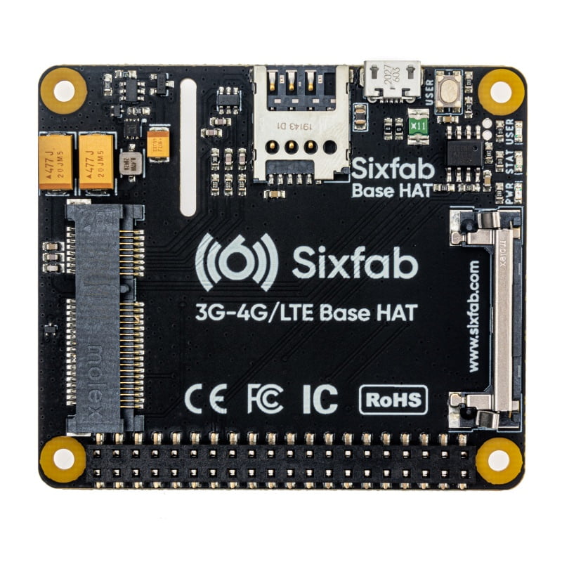
You can insert 3G/4G & LTE mini PCIe modules and this Base HAT becomes a bridge between Raspberry Pi and modem. This cellular HAT provides simplified data connection for remote IoT projects, on the field, across the globe, everywhere. Start using a high-speed LTE connection with low power consumption in a slim form factor with all necessary soft...
lone silo
Yes, GSM/LTE
 agile depot
What's the maximum sample rate and bit depth of the Raspberry Pi Zero W's I2S audio input? I'm hoping to input a 96-192khz 24 bit I2S signal and have it act as a USB microphone/line in device on my laptop via the onboard USB OTG port
 frosty robin
forgive me if im wrong but this should be fine correct?
 swift sky
agile depot
What's the maximum sample rate and bit depth of the Raspberry Pi Zero W's I2S au...
swift sky
agile depot
What's the maximum sample rate and bit depth of the Raspberry Pi Zero W's I2S au...
I am not sure you understand how USB and digital audio work. If so, this may help:
https://www.edn.com/fundamentals-of-usb-audio/
Somewhere before the USB port the analog signal from the mic has to be converted to digital, unless the mic is already a USB mic. But why do you need 96/192 - 24bit? I am not sure such high resolution USB mics exist. 16/44.1 is fabulous for must of us.
agile depot
What i meant is that i have a 192khz 24bit I2S signal that id like to translate into a USB audio input for my laptop. Almost like a USB microphone, but without the microphone.
I just need to know if the pi can handle such a high resolution I2S signal
worn drift
lament swan
I know it's just wishful thinking but I was wondering if there was a way to do i...
you can call your python script like this: /full/path/to/virtualenv/python /full/path/to/yourscript.py such as /home/pi/virtualenv/bin/python /home/py/myscript.py
in your python script, i think you can also do as the very first shebang line: #!/path/to/virtualenv/bin/python and then that should work with ./myscript.py on command line 👍
swift sky
agile depot
What i meant is that i have a 192khz 24bit I2S signal that id like to translate ...
So maybe look for a USB sound interface (say at Sweetwater) that can produce 94/128 24bit, and see what USB port it requires (probably USB 3 or USB c) and then see if the USB ports on your PI are spec'd that high.
agile depot
swift sky
So maybe look for a USB sound interface (say at Sweetwater) that can produce 94/...
It should work with USB 2.0 right?
 swift sky
agile depot
It should work with USB 2.0 right?
swift sky
agile depot
It should work with USB 2.0 right?
It claims USB 2.0, I would use a Pi 4 USB C. You can get it at Amazon, and return it if doesn't work. But you will need some software on the PI side. Focusrite might have software for Linix, but it probably won't run on an ARM/Pi processor. Also notice the specs say "Compatibility: USB-C iPad Pro " and "Power Supply: USB bus powered ".
agile depot
I'm not planning on using this, i was just showing that 192khz 16 bit audio can be put through USB 2.0
Which the Pi Zero W i plan on using has
half nexus
Geniuent pi OS question, why does it has urge to reset all of the gui settings when changing an Appearance Default.
Looking at the labels it should change nothing but a gui scale, but apart with that it changes whole environment to default
||It's good to have a panic button that reverts everything back (when you messed with LXappearance perhaps), just it's not the job of a screen scale changer||
 glass yew
worn drift
in your python script, i think you can also do as the very first shebang line: `...
glass yew
worn drift
in your python script, i think you can also do as the very first shebang line: `...
Side question ... using default Raspbian on a Pi 4 .. can I assign an icon on the GUI to a script (like ./myscript.py) ??
faint sparrow
I use 'wbar' on Debian (amd64 desktop) which has a config tool to specify the exact icons it uses.
glass yew
faint sparrow
I use `'wbar'` on Debian (amd64 desktop) which has a config tool to specify the ...
great! I will try that .. thanks
faint sparrow
;) pretty sure I did run 'fluxbox' with 'wbar' on Raspbian. fluxbox the window manager. I kept 'pi' as the factory set it up and added another user with same privs, with my preferred stuff.
analog ore
analog ore
hey, can you guys help me?
I'm trying to USB boot my CM4, modified the bootloade...
Still need help here pls
 robust copper
Hello, I have an issue with I2C with Adafruit motor HAT for RPi. More info and screenshots are in thread at #help-with-circuitpython
worn drift
glass yew
Side question ... using default Raspbian on a Pi 4 .. can I assign an icon on th...
i'm like 99.9% sure you can but i don't know how to do it, i rarely use linux gui. i think you might be able to right click and choose an icon or something like that 🤷
dusk flower
glass yew
Side question ... using default Raspbian on a Pi 4 .. can I assign an icon on th...
You can make a script.desktop file, recalling your script and using an icon of your choice
glass yew
dusk flower
You can make a script.desktop file, recalling your script and using an icon of y...
I will look into that &, try it .. ty
ornate bluff
Anyone know how to get Realtek RTL8152 working with a Pi 1 model B?
It plugs in and is shown on lsusb, but doesn't show up as an adapter on ifconfig
never mind, I just hadn't configured it as an adapter yet
swift sky
agile depot
Which the Pi Zero W i plan on using has
How do you plan on sending the signal to the USB port?
analog ore
analog ore
hey, can you guys help me?
I'm trying to USB boot my CM4, modified the bootloade...
Can you guys help me with this please?

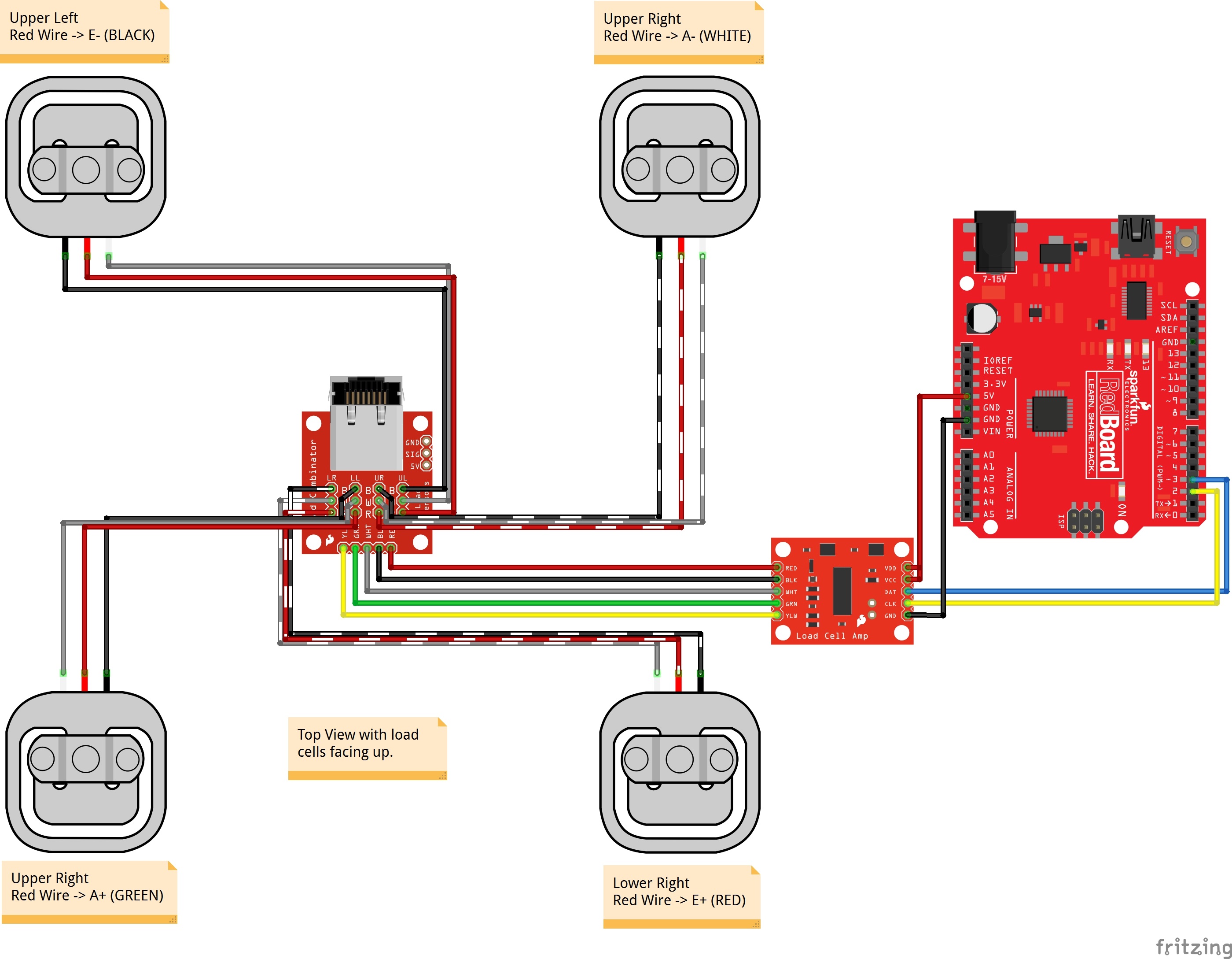 dusk flower
 mint pagoda
Got me a Pi4B -Yes!
mint pagoda
Got me a Pi4B -Yes!
OwO
fickle rose
mint pagoda
Got me a Pi4B -Yes!
Tell me how
ornate bluff
Hey so I'm trying to use one of these mini Pi TFT displays, and I get static issues on it. So on this page https://learn.adafruit.com/adafruit-mini-pitft-135x240-color-tft-add-on-for-raspberry-pi/kernel-module-troubleshooting it suggests I pin the kernel version, which works, but then I re-run the script as it suggests, and the script updates the kernel again. How do I fix this? Thanks
(I'm also working on a Pi 1 B)
civic rune
what's a good way to turn off a pi that I can't SSH into and also can't get the HDMI output to display anything?
vocal lava
wire a button to it? One of the pins defaults to power for a button
civic rune
doesn't that require listener code?
vocal lava
No
civic rune
how do I tell if it's turned off? Didn't think of that
the act light isn't flashing but there's a bit of a spark in there
vocal lava
Well, the same button could turn it on. Here's the example: https://www.instructables.com/Raspberry-Pi-Power-Button/
civic rune
yeah I was aware of the power on functionality but it was my impression that the power off required code in the background
I might just pull the plug, I have everything backed up
ok, force reboot is risky but it seems to have paid off.
 sharp patrol
How often does a 4b 8gb model go in stock on adafruit, is there a set time it would go in stock?
meager girder
my answer to that is good luck
I don't think it's a predictable phenomena in any way
civic rune
Having an issue with some really simple code/hardware
I have a SPST-NO button wired with one wire to D5 and one to GND. I have this code with Blinka
>>> import board, digitalio
>>> button = digitalio.DigitalInOut(board.D5)
>>> button.direction = digitalio.Direction.INPUT
then I run:
>>> button.value
>>> True
then I depress the button and run
>>> button.value
>>> True
I should be reading false.... I am really confused.
in fact when my circuit is wired up with the input pullup done in software, I read continuity between the pins of my button
anyone got any clues?
twin helm
civic rune
in fact when my circuit is wired up with the input pullup done in software, I re...
please explain what you mean by "read continuity between the pins"?
twin helm
resistance or continuity readings with a DMM are very difficult to interpret if there are any active or frequency-dependent components present, especially if they're powered on
civic rune
hmm
twin helm
have you confirmed with your DMM that the switch on its own is operating as you expect?
civic rune
well I just disconnected something that's been causing trouble in the circuit and now they don't read as connected but the code still doesn't work
I have
all powered off, it works normally
I lied, removing the something didn't help after all
This is very odd
twin helm
jumper (or wire a 1k resistor or so) from D5 to ground and see how that reads?
twin helm
(helps to limit the current if the pin is accidentally set to output)
1k should be stronger than the internal pullup
civic rune
button.value is still True
oh hey
guess who is a goofus
PIN 5 != D5
sigh
it worked!
ok
I'm not losing my mind, yet
 thin pelican
Recommendations for a portable battery pack for pi400?
thin pelican
civic rune
I'm not losing my mind, yet
I keep telling myself that.
edgy oar
One of my daily affirmations, too.
civic rune
when using nano, shouldn't CTRL+O save your file wherever you opened the nano instance?
because the file I'm trying to create is not appearing in the file manager and I can't find it with sudo find
tired marsh
if you have the rights
civic rune
I mean I should?
tired marsh
if not, it should tell you what it's doing
civic rune
I used sudo nano
and I am a sudoer
it said "wrote out x lines"
I've done this before on this exact pi and it worked fine
I guess I can try not using nano and then use sudo mv
tired marsh
dunno, make sure you are looking the the right place 🤷
ornate bluff
Does anyone know of a good library for using buttons on GPIO pins? That allows for detecting combinations of buttons pressed, holding buttons, double taps, triple taps, etc?
civic rune
is gamepad still used?
rotund pivot
module deprecated in favor of keypad (gamepad module went away earlier; gamepadshift module went away in 8)
civic rune
ornate bluff
Does anyone know of a good library for using buttons on GPIO pins? That allows f...
maybe check out keypad as Anecdata mentioned, it's the one I was thinking of
civic rune
I found a guide for making an image of your pi using an USB thumb drive. I don't have one on hand but I do have a USB SD card reader + card. Workable?
 lost wolf
civic rune
I found a guide for making an image of your pi using an USB thumb drive. I don't...
lost wolf
civic rune
I found a guide for making an image of your pi using an USB thumb drive. I don't...
Potentially yes. I've had it act the same before, other times, total failure.
Worth trying, you should know quickly if it's not going to work.
At least I assume if it images properly, it should allow for the image to be used successfully as well.
Don't bet on it until you're certain though. 😄
 ember gyro
hello, anyone here done anything with restaurant menu boards? im wondering if i could create some sort of enclosure that would withstand houston heat outdoors.
 sacred swift
Hello, I'm new to Raspberry PI and CircuitPython. I'm trying to utilize the Adafruit VL5L1X Flight Distance Sensor. I followed the learn page and modified the code to fit my Raspberry PI PICO RP2040, but I keep getting a Clock stretch too long error. Solders are fine, wires are all intact and connected to the correct pins, heres the code.


I haven't done any locking or unlocking yet, since the error occured before and after I added the code.
May be the wrong channel..., does this channel do code help?
lost wolf
sacred swift
May be the wrong channel..., does this channel do code help?
Welcome! Yes. You're in the right place. You could also have posted to #help-with-circuitpython, but we discourage cross-posting, and this channel should work. Most folks here are community members volunteering their time around other obligations, so please be patient. Folks who have knowledge of the topics usually check those channels.
lament swan
sacred swift
Hello, I'm new to Raspberry PI and CircuitPython. I'm trying to utilize the Adaf...
I'm not sure what this error is. You can start by running your code in debug mode line by line to identify which of the lines is running into that error and take it from there. I would hazard that it could be timing_budget variable that you could fidget with but I could be wrong.
lost wolf
There are issues with certain I2C devices and Raspberry Pi clock stretching. I don't know the details, I only know that it's a thing. I'm hoping someone who has dealt with it can chime in.
lament swan
ornate bluff
Does anyone know of a good library for using buttons on GPIO pins? That allows f...
I really like pigpio https://abyz.me.uk/rpi/pigpio/
Raspberry Pi Reg. C GPIO library and Python GPIO module and shell command utilities to control the GPIO, including SPI, I2C, and serial links.
sacred swift
I've looked all over the internet and cant really find anything that makes sense, or relates to my problem. It has something to do with the i2c = busio.I2C(board.GP11, board.GP10)
lament swan
civic rune
I used `sudo nano`
Strange, I've used ctrl+S before. The commands are at the pallette at the bottom, no? Also, if you hit Ctrl+X, it should ask you if you want to save or not
sacred swift
The function takes an extra (optional) parameter of "frequency", but even if I plug that in it still sends the same error
lost wolf
sacred swift
The function takes an extra (optional) parameter of "frequency", but even if I p...
Like I said, it's a known issue, but I don't know details, or how to deal with it. Maybe search forums.adafruit.com for "clock stretching" and see if it was ever discussed there.
Someone might have, and there might be a fix in the thread.
sacred swift
I solved the issue
I was using a resistor for the pullup that was too low of an ohmage
Which made the signal mess up between the two boards
sacred swift
Well...
Now I've got another problem

I put 29 address in since that is the default address for the Flight Sensor, but now I'm getting an address error
But I'm not sure if this is caused by my janky resistor setup
lost wolf
You're welcome! That's why we're here, why we started this Discord server in the first place. 🙂
sacred swift
Is there a way to scan all devices connected to the PICO? Its still giving me the No I2C device at address: 0x29
sacred swift
Yes RP2040
lost wolf
The scan code is here: https://learn.adafruit.com/circuitpython-essentials/circuitpython-i2c#find-your-sensor-2985153
 vocal lava
Do you have to pass it the I2C address? I only ask because the example code does not: https://learn.adafruit.com/adafruit-vl53l1x/python-circuitpython
lost wolf
Good call, Paul. I don't think you do if you're using default.
sacred swift
If I do not pass the I2C address it gives me function parameter error
I cant use "board" for the I2C function
As it doesnt have the property for me, only "busio" has it
lost wolf
LLama, is the power LED on on the ToF sensor?
sacred swift
Yes, its on
lost wolf
sacred swift
As it doesnt have the property for me, only "busio" has it
Accurate, because Pico.
Ok, that's good. Figured I'd ask.
Try the scan code? Except change the setup to use the Pico suggested set up line.
sacred swift
But the Pico doesnt detect the board, so I guess my wiring isnt connected. But its odd, since if it wont run the code until I put in the correct pins, implying it knows those pins are connected to something...
GP0 and GP1 dont work, the defaults
I put them in the GP11 and GP10 pins
GP11 for SDA and GP10 for SCL
lost wolf
Not all pins work as I2C, I think. Most of them do, though. The RP2040 has bonkers capabilities on every pin.
sacred swift
Dang
lost wolf
But, there's a thing where you have to use pins in a certain I2C group.
lost wolf
Do you have a GP24 and a GP25? They will work as SDA and SCL respectively.
GP3 and GP2 will also work, SCL SDA in that order.
lost wolf
Nice!
@sacred swift FYI this channel is more about Raspberry Pi computers than it is the Pico. I didn't realise that's what you were using initially. So next time, if you have more questions, post to #help-with-circuitpython. Good luck!
robust copper
Can I use both SERVO HAT and MOTOR HAT if I use tall headers for one of them?

 alpine fox
i'm having trouble getting the https://www.adafruit.com/product/4863 cyberdeck hat and the Pimoroni HyperPixel - 4.0" Hi-Res Display https://www.adafruit.com/product/3578 to work on the raspberry pi 400
Cyber-warriors, listen up here! We’ve got with some zero-day unreleased hardware we just dumpster-dived. Now you can crack kodes, and write skripts with style, thanks to the CYBERDECK ...
Pimoroni's HyperPixel features a 4.0" display with 800x480 18-bit color pixels and a capacitive touch overlay, making it more sensitive and responsive than a resistive touch ...
i followed all the instructions but all that happens is the backlight goes on and the pi no longer displays on hdmi
 fresh marsh
could someone explain the difference between the cberdech hat an bonnet to me please?
I am trying to figutr out how to attach a pimoroni hyperpixel 4 inch display to the pi 400
alpine fox
hat is taller and is meant for regular raspberry pi hats, the bonnet is meant for hats used on the pi zero & zero 2
civic rune
Can some cheap displays not work with the pi? (3A+). I bought a cheap almost literally no name HDMI display off of Amazon and it just doesn't seem to work
umbral sable
civic rune
Can some cheap displays not work with the pi? (3A+). I bought a cheap almost lit...
Does it work from another HDMI source like your laptop/PC?
meager girder
man these displays seems to be a huge problem
couple of unsolved questions about them lately
civic rune
Oooof
Doesn't work with my PC either
Got some e waste on my hands
That's frustrating
meager girder
I meant displays generally not that specific one
and you dont have a pi 4 do you ?
mint pagoda
@fresh marsh The Adafruit Cyberdeck HAT was developed to give easier access to the I/O of the Pi-400. The Alignment Key also reduces the probability that an extension cable could be installed incorrectly and get the pin alignment 180 degrees out. The Cyberdeck also provides some ready made connections (STEMMA/STEMMA QT) for adding external sensors.
The Cyberdeck Bonnet just allows for a more Low Profile setup.
AND @fresh marsh in reference to your HyperPixel issue., you have to either cut a trace or remove a diode on the board. https://learn.adafruit.com/cyberdeck-bonnet-and-hat/fixing-pin-conflicts#option-1-cut-a-trace-3104511-6.

Adafruit Learning System
HATs and Bonnets at a jaunty angle!
fading idol
I have an Stemma QT SHIM for a Raspberry Pi (Product ID 4463). I am trying to connect it to a NeoPixel strip with a 3 pin JST SM connector on each end. I need to go from the Stemma QT connector to the JST SM. Is there a cable to do that or do I just need to make my own?
lost wolf
fading idol
I have an Stemma QT SHIM for a Raspberry Pi (Product ID 4463). I am trying to c...
There isn't a cable for that. I usually use the STEMMA QT to male header pins, and plug three of them into the NeoPixel strip. But you could definitely make your own as well.
fading idol
lost wolf
There isn't a cable for that. I usually use the STEMMA QT to male header pins, a...
Thank you for the fast response! I appreciate the info!
lost wolf
You're welcome!
 upbeat oasis
Hello, do these instructions work with the raspberry pi 4? it isn't listed in categories but i thought that might just be because they didn't update the page https://learn.adafruit.com/fona-tethering-to-raspberry-pi-or-beaglebone-black/wiring

Adafruit Learning System
Connect your Linux board to the internet through a cellular data connection with FONA!
 tidal crest
Hi, does anyone know how to autorun 2 python scripts (a GUI script and a server script) together. Unfortunately only the GUI file gets executed, the server file not
(on raspi)
meager girder
what's the fastest way to connect remotly/wirelessly to my rpi2 which is a bit unwieldy to connect on locally (touch screen would have to plug keyboards/mouses/etc) ?
twin helm
is having only the command line OK, or do you want the GUI?
 modern matrix
on today's Pi 4, are there any back-powering issues powering the board via GPIO while connecting the USB-C port to a PC (running in peripheral/gadget mode)? I've seen fragments of discussions online about it (more for the Zero) but haven't found a real "yes it's fine" or "that's going to cause problems" or "here's the cable you need".
faint sparrow
The GPIO is a 5V output, not an input. It's provided to power exteral devices via the GPIO bus. It's bonded directly to VBUS from the USB-C power-in connector.
faint sparrow
I'd be more comfortable sealing off the USB-C connection if I was using the GPIO pins for 5V input, so that a second power supply cannot be also connected (via USB-C).
civic rune
I am following this guide to backup my pi as an image https://www.tomshardware.com/how-to/back-up-raspberry-pi-as-disk-image but I'm stuck on step 7. It's telling me that myimg.img is not a file. However step 5 says to only do it if you previously shrunk the partition on your thumb drive? Yet that seems to be where myimg.img is created, no?