#help-with-arduino
1 messages · Page 107 of 1
 leaden walrus
yah, don't use 13. the sketch uses the LED, so will take that pin.
pinMode(LED_BUILTIN, OUTPUT);

 violet shell
when I do that later on in the code it says that dev_I2c isn't declared
leaden walrus
ok. different way. put this line back to:
LSM6DSLSensor AccGyr(&dev_i2c, LSM6DSL_ACC_GYRO_I2C_ADDRESS_LOW);
leave the other commented out but add this new line:
//TwoWire dev_i2c(I2C2_SDA, I2C2_SCL);
#define dev_i2c Wire
// Components.
//TwoWire dev_i2c(I2C2_SDA, I2C2_SCL);
#define dev_i2c Wire
LSM6DSLSensor AccGyr(&dev_i2c, LSM6DSL_ACC_GYRO_I2C_ADDRESS_LOW);
ok so the code has managed to upload to the feather but nothing comes up in the serial monitor
leaden walrus
looks like it only prints something if tilt is detected
  // Initialize serial for output.
  SerialPort.begin(9600);
  while (!SerialPort);
  SerialPort.println("Tilt Test");
can do something like that to wait for serial monitor to open and print a start message
violet shell
only prints out tilt test into the serial moitor
so the code i am trying to get is to tell me the acceleration and tilt direction, then store this data into a csv file with more data from other components as well
would it be easier to send the code i have so far for the bmp280 that i am using?
and the data that it reads gets stored to the sd card?
leaden walrus
not really. if thats working then it should be fine.
looks more like a basic data dump
could also see if the adafruit library is easier to use:
https://github.com/adafruit/Adafruit_LSM6DS
violet shell
ok will try the first link you kindly sent over
ok so i used the code from the first link but comes up with this message,

 rough torrent
I would still try to upload it
If it doesn't work, then you will have to use a different board that uses one of the architectures supported by the library or a different library that supports your architecture
violet shell
ok so i've uploaded the code now but doesn't give me the values in the serial monitor
it just outputs all as 0
rough torrent
Sounds like a failure to read from I2C bus or you didn't set up the device correctly
violet shell
rough torrent
Sounds like a failure to read from I2C bus or you didn't set up the device corre...
ok
violet shell
shall i send a photo of how i've connected the component to the board

 rough torrent
Try the Adafruit library?
Does the device / feather have pullups? I don't think featheres come with pull ups for the I2C bus
violet shell
rough torrent
Try the Adafruit library?
which file would i use instead?
violet shell
rough torrent
Does the device / feather have pullups? I don't think featheres come with pull u...
not sure i understand what i mean
rough torrent
violet shell
which file would i use instead?
Install the Adafruit_LSM6DS library in the library manager for Arduino IDE
Then open examples and find the example for that library
You should scan through the code to make sure there are no pin definitions you need to change, then upload
violet shell
do i open the .h or the .cpp version for the LSM6DSL?
rough torrent
violet shell
not sure i understand what i mean
The I2C bus requires "pull-ups" to keep the pins at a know voltage, and won't float
Notorious for being finicky about it
rough torrent
violet shell
do i open the .h or the .cpp version for the LSM6DSL?
You shouldn't need to, just download the library through the Arduino library manager

 rough torrent
don't think it particularly matters, but latest version is always good
then choose an example

seems like there are different examples for different variations
Probably want to try the sketches ending in "test"
violet shell
will these still work if my component is LSM6DSL but the test code is for the LSM6DS33
rough torrent
I'm not sure, I'm not familiar with the component
You might want to try all of the test sketches :/
rough torrent
leaden walrus
maybe try this example:
<https://github.com/stm32duino/LSM6DSL/blob/main/example...
Was this the original example you used?
Actually can you send the example with the modifications cater suggested?
violet shell
yh sure
violet shell
// Includes.
#include <LSM6DSLSensor.h>
#define SerialPort Serial
#define I2C2_SCL    SCL
#define I2C2_SDA    SDA

// Components.
//TwoWire dev_i2c(I2C2_SDA, I2C2_SCL);
#define dev_i2c Wire
LSM6DSLSensor AccGyr(&dev_i2c, LSM6DSL_ACC_GYRO_I2C_ADDRESS_LOW);

void setup() {
  // Led.
  pinMode(LED_BUILTIN, OUTPUT);
  // Initialize serial for output.
  SerialPort.begin(9600);

  // Initialize I2C bus.
  dev_i2c.begin();

  // Initlialize components.
  AccGyr.begin();
  AccGyr.Enable_X();
  AccGyr.Enable_G();
}

void loop() {
  // Led blinking.
  digitalWrite(LED_BUILTIN, HIGH);
  delay(250);
  digitalWrite(LED_BUILTIN, LOW);
  delay(250);

  // Read accelerometer and gyroscope.
  int32_t accelerometer[3];
  int32_t gyroscope[3];
  AccGyr.Get_X_Axes(accelerometer);
  AccGyr.Get_G_Axes(gyroscope);

  // Output data.
  SerialPort.print("Acc[mg]: ");
  SerialPort.print(accelerometer[0]);
  SerialPort.print(" ");
  SerialPort.print(accelerometer[1]);
  SerialPort.print(" ");
  SerialPort.print(accelerometer[2]);
  SerialPort.print(" | Gyr[mdps]: ");
  SerialPort.print(gyroscope[0]);
  SerialPort.print(" ");
  SerialPort.print(gyroscope[1]);
  SerialPort.print(" ");
  SerialPort.println(gyroscope[2]);
}
this is the code which outputs to the serial monitor but not the actual values
rough torrent
Can you edit the message and use code blocks?
See #welcome message
It makes it much easier to read
violet shell
yh sure
#include <LSM6DSLSensor.h>
#define SerialPort Serial
#define I2C2_SCL SCL
#define I2C2_SDA SDA
// Components.
//TwoWire dev_i2c(I2C2_SDA, I2C2_SCL);
#define dev_i2c Wire
LSM6DSLSensor AccGyr(&dev_i2c, LSM6DSL_ACC_GYRO_I2C_ADDRESS_LOW);
void setup() {
// Led.
pinMode(LED_BUILTIN, OUTPUT);
// Initialize serial for output.
SerialPort.begin(9600);
// Initialize I2C bus.
dev_i2c.begin();
// Initlialize components.
AccGyr.begin();
AccGyr.Enable_X();
AccGyr.Enable_G();
}
void loop() {
// Led blinking.
digitalWrite(LED_BUILTIN, HIGH);
delay(250);
digitalWrite(LED_BUILTIN, LOW);
delay(250);
// Read accelerometer and gyroscope.
int32_t accelerometer[3];
int32_t gyroscope[3];
AccGyr.Get_X_Axes(accelerometer);
AccGyr.Get_G_Axes(gyroscope);
// Output data.
SerialPort.print("Acc[mg]: ");
SerialPort.print(accelerometer[0]);
SerialPort.print(" ");
SerialPort.print(accelerometer[1]);
SerialPort.print(" ");
SerialPort.print(accelerometer[2]);
SerialPort.print(" | Gyr[mdps]: ");
SerialPort.print(gyroscope[0]);
SerialPort.print(" ");
SerialPort.print(gyroscope[1]);
SerialPort.print(" ");
SerialPort.println(gyroscope[2]);
}
is that better?
rough torrent
Yes, thank you!
Although you can do:
```arduino
<code>
```
to syntax highlight it
(Right now I'm looking at the library)
leaden walrus
looks like breakout includes pullups

might be worth an i2c scan to verify the address:
https://learn.adafruit.com/scanning-i2c-addresses/arduino
the LSM has two interrupt outputs, but the breakout only maps one at a time to its INT pin, via jumper
not sure what STM library ends up using
rough torrent
Can you also try replacing this:
// Read accelerometer and gyroscope.
int32_t accelerometer[3];
int32_t gyroscope[3];
AccGyr.Get_X_Axes(accelerometer);
AccGyr.Get_G_Axes(gyroscope);
with something like this? (untested and may not compile)
// Read accelerometer and gyroscope.
int32_t accelerometer[3];
int32_t gyroscope[3];
LSM6DSLStatusTypeDef result = AccGyr.Get_X_Axes(accelerometer);
SerialPort.print("Get X axes result: "); Serial.println(result);
result = AccGyr.Get_G_Axes(gyroscope);
SerialPort.print("Get G axes result: "); Serial.println(result);
What does the serial monitor say then?
leaden walrus
^^ yep. keep trying the basic print example. without interrupts tie in.
rough torrent
(I'm not sure if that's the correct syntax, C isn't my strong suit lol)
leaden walrus
the STM example is #def the serial port for some reason
leaden walrus
so code needs to be SerialPort.print etc
violet shell
this is what the monitor comes out with
 rough torrent
That looks like it's happy with reading the results, as LSM6DSL_STATUS_OK = 0
Hmmmm...
leaden walrus
check begin() call return also
rough torrent
Yea
So replace
AccGyr.begin();
To:
LSM6DSLStatusTypeDef status = AccGyr.begin();
SerialPort.print("Begin status: "); Serial.println(status);
And, maybe try something like this?
// Read accelerometer and gyroscope.
int32_t accelerometer[3] = {1, 2, 3};
int32_t gyroscope[3] = {4, 5, 6};
LSM6DSLStatusTypeDef result = AccGyr.Get_X_Axes(accelerometer);
SerialPort.print("Get X axes result: "); Serial.println(result);
result = AccGyr.Get_G_Axes(gyroscope);
SerialPort.print("Get G axes result: "); Serial.println(result);
If it still is 0, then the sensor itself not the library may be returning bad values
violet shell
same results of all 0's
rough torrent
Hmmmmmmmm, the sensor might not be initialising correctly, or possibly broken?
Also have you ran the I2C bus test to detect address?
Sorry, but I gtg - Hopefully you get your sensor to work!
Hopefully you don't end up needing to buy another/different one 🙏
(But if you do end up doing so, Adafruit products are really nice with excellent documentation 😉 )
violet shell
rough torrent
Hmmmmmmmm, the sensor might not be initialising correctly, or possibly broken?
A...
not sure how to do this but will have a look at an adafruit component
violet shell
rough torrent
Sorry, but I gtg - Hopefully you get your sensor to work!
Hopefully you don't en...
are there any recommendations for gyroscopes and accelerometers combined?
 sacred ivy
This is a general C question thats applicable to arduino, but is char/byte the smallest variable I can use?
 north stream
sacred ivy
This is a general C question thats applicable to arduino, but is char/byte the s...
north stream
sacred ivy
This is a general C question thats applicable to arduino, but is char/byte the s...
Kinda: There is a bool/boolean type, but it's implemented as a byte 😕
You can use bitfields, however.
 rough vessel
Yeah, that's a yes-or-no question with not quite a yes-or-no answer. It sorta depends on context and why you're asking. Generally speaking, it's a yes. 🙂
sacred ivy
It just seems silly to waste a whole byte when I only need set a bit on or off. Im sure theres a way around it
rough vessel
Alas, that's often just a cost you have to eat. If you have more than one bit like that, you can always pack them all into a byte and use a bitfield as @north stream mentioned.
It's worth keeping in mind that as long as you have memory to spare, it's not being wasted. It might be worth trying to optimize if you run out of space on the device, but until then it's not usually worth the extra effort which can be spent elsewhere.
sacred ivy
True.
north stream
Back in my PIC days, I used bitfields a lot, but that's because a) the PIC ISA is optimized for bitwise operations, and b) I was programming in assembler.
sacred ivy
north stream
Back in my PIC days, I used bitfields a lot, but that's because a) the PIC ISA ...
👀 I have XC8 open now and Im using it to train myself in C lol. Its a simple project, a "coffee/tea timer"
 quartz furnace
Projects on the ESP32 using WiFi to send email. I see google is going to stop allowing "less secure Apps on 5/30/2022. Anyone have a good email service to migrate to? or know of anyother way (note I have used 'Pushover")
ahhh, I left out Adafruit IO
But just looking for any kinda of notification service.. email.. or push service
 elfin thorn
Hi y'all! I'm playing around with the TEA5767 I2C board connected via I2C to the Clue.
The sketch is pretty simple:
``// TEA5767 Example
#include <Wire.h>
#include <TEA5767Radio.h>
TEA5767Radio radio = TEA5767Radio();
void setup()
{
Wire.begin();
radio.setFrequency(25.6); // pick your own frequency 25.6, 29.9, 37.8, and 37.9 MHz
}
void loop()
{
}``
But what I want to do is make one of the buttons on the Clue change the frequency. I am utterly Clueless (ha ha) about Arduino, so is there a simple button sketch I can use to do this? Thanks!
 wind nexus
So im driving a 2amp nema 17 with an Easy motor driver thats rated for 750ma. Is there another driver - library anyone would recommend to make use of the full 2amps?
 pine bramble
What are called those display without exposed pcbs?
 pine bramble
Does anyone know how to change waveform in an arduino code for "tone"
north stream
I think they're basically square waves, but you can use PWM to change the duty cycle, or analog filtering to change the waveshape. After that, you get to various DAC techniques.
pine bramble
Ok thx and how do I do that? Sorry I'm kind new to audio stuff and decent-ish at arduino
north stream
One easy way to change the duty cycle is use Paul's TimerOne library instead of the tone one. https://github.com/PaulStoffregen/TimerOne
GitHub
TimerOne Library with optimization and expanded hardware support - GitHub - PaulStoffregen/TimerOne: TimerOne Library with optimization and expanded hardware support
pine bramble
Thx, sir?(sorry just trying to use the correct pronouns)
north stream
Good point, I probably should add my pronouns (he/him)
pine bramble
Ok sir
Btw good pfp
Right now my main goal is setting up the main 4 wave forms(sine, square, sawtooth, and triangle)
pine bramble
How do I do analog filtering
pine bramble
How do I change the waveshape, sorry to ask again
pine bramble
Also is it possible to make grain/fuzz/dist effects and reverb with arduinos?
Again sorry for asking so many questions
north stream
pine bramble
Right now my main goal is setting up the main 4 wave forms(sine, square, sawtoot...
You'll need an ADC, a dedicated chip, or a bunch of dedicated waveshaping circuitry to do that.
 livid osprey
pine bramble
What are called those display without exposed pcbs?
livid osprey
pine bramble
What are called those display without exposed pcbs?
I don’t think there is a particular name for those without. Those with are sometimes referred to as “breakout board” to identify the extra pcb that exposes a pin header interface, but I can’t think of a term to distinguish the breakout-less displays…
pine bramble
north stream
You'll need an ADC, a dedicated chip, or a bunch of dedicated waveshaping circui...
I thought I needed a DAC
north stream
pine bramble
I thought I needed a DAC
You're right, I misspoke: a DAC
 past beacon
I need to know how to take data from a sensor (in my case a Barometer) and compute the data feed to read a specific value and set it in a inequality function. For example, an if or when/else statement that is linked to a servo. When the barometer value exceeds 750 the servo rotates. I don't need help writing just guidance on where to find out more about these types of operations and what they are technically called. Thanks
north stream
past beacon
I need to know how to take data from a sensor (in my case a Barometer) and compu...
For reading from sensors, there are usually libraries available that provide the sensor values. Similarly, there is a Servo library that you can give an angle and it will direct the servo to rotate to that angle. Then the code basically boils down to "periodically, read the sensor, compare the value to the threshold, set the servo to angle1 if above threshold, or angle2 if below it"
pine bramble
livid osprey
I don’t think there is a particular name for those without. Those with are somet...
Alright thanks
Edit: borderless display seem to work as a tag, more or less
past beacon
north stream
For reading from sensors, there are usually libraries available that provide the...
I have the library to read the data and print into the Serial monitor, I'm having difficulty understanding how to get the program to read/use those values.
north stream
past beacon
I have the library to read the data and print into the Serial monitor, I'm havin...
If you have a sample like: Serial.println(mysensor.read());, you'll first have to find out what kind of data the sensor returns. If the sample code puts the sensor value into a variable, that part is already done for you.
past beacon
north stream
If you have a sample like: `Serial.println(mysensor.read());`, you'll first have...
That helps out more than you know, thanks!
pine bramble
hi all. I have a arduino nano rp2040 connect. I need to use it as a USB host. What should I do to make that work?
Accomplishments include: reading a usb device's Device ID, or anything about the device, then eventually work my way to being able to send a Nintendo switch rcm payload.
north stream
pine bramble
hi all. I have a arduino nano rp2040 connect. I need to use it as a USB host. Wh...
There are a few possibilities. You can use the tinyusb_host port to implement it with the main CPU, or Pico-PIO-USB to implement it with PIO, or use a separate USB host chip like a MAX3421 to do the heavy lifting.
 pine bramble
north stream
There are a few possibilities. You can use the tinyusb_host port to implement i...
pine bramble
north stream
There are a few possibilities. You can use the tinyusb_host port to implement i...
tinyusb_host is on micropython?
okay nevermind 😛 it's C
I can attempt to see what fusee gelee ports exist for c.
rough torrent
displayBegin in Adafruit Arcada when compiled in PlatformIO freezes - posted debugging details here: https://github.com/adafruit/Adafruit_Arcada/issues/44

GitHub
Trying to use Adafruit Arcada in PlatformIO, arcada.displayBegin() causes the PyGamer to freeze. Repro: Create PlatformIO project. Install Adafruit Arcada. Copy test sketch below to main.cpp. Go to...
If anyone has any debugging suggestions they would be greatly appreciated
quartz furnace
I have a question on how to handle this line of code
" esp_err_t result = esp_now_send(broadcastAddress2, (uint8_t *) &myData, sizeof(myData));"
I want to do broadcastAddress1 then broadcastAddress2
I am getting edeclaration of 'esp_err_t result'
how do I loop and pass "address1" then "address2"
Also is broadcastAddress* a Char?
would I need to declair a Char? then just rename?
thinking in a For i loop? and once i = 2 then change and pass it to the line?
north stream
You just need to declare your result variable once. I like to do it separately: ```arduino
esp_err_t result;
result = esp_now_send(broadcastAddress1, ...);
// check result
result = esp_now_send(broadcastAddress2, ...);
// check result
Ohhhhhh
north stream
If you put your addresses in an array, it's easy enough to loop over them
I'm not familiar with the call, so I don't know what type it accepts.
quartz furnace
Perfect! Thanks haha tried so many diffent ways like creating a 2nd esp_err_t2 it didn't like that hahaha
north stream
You could have two different result variables with different names, but I think it makes more sense to just have one and re-use it.
quartz furnace
Works well Thanks again 🙂
 glacial pond
Ugh, I'm sure this has come up before, but this is the first time I've run into it. I'm on macOS Monterey and have python@3.9 3.9.10 installed and up to date (per brew), which is /usr/bin/python3. The Arduino IDE won't compile the blink sketch for my FunHouse. Error is
exec: "python": executable file not found in $PATH
I agree that there is no "python" executable in my path. How do I get it to recognize/use python3?
 solemn cliff
glacial pond
Ugh, I'm sure this has come up before, but this is the first time I've run into ...
solemn cliff
glacial pond
Ugh, I'm sure this has come up before, but this is the first time I've run into ...
it looks like brew install python will link python to python3. (Personally I use pyenv, so as to not depend on brew updating python under me)
glacial pond
solemn cliff
it looks like brew install python will link python to python3. (Personally I use...
Sadly, it does not. I even tried reinstalling python. Thank you for the thought -- I'll look into pyenv if I'm still stuck the next day I have maker time
solemn cliff
oh, is that on M1 by the way ?
glacial pond
Nah, Intel
north stream
glacial pond
Ugh, I'm sure this has come up before, but this is the first time I've run into ...
I'll often make a Python environment by using the full path to Python: ```
/usr/local/Cellar/python/3.9.10/bin/python3 -m venv venv
Then after activating that environment, the correct Python will be in my Path.
 tired notch
Hello im using ssd1351 and adafruit library how can i change the gray scale of my display?
north stream
tired notch
Hello im using ssd1351 and adafruit library how can i change the gray scale of m...
When you say "change gray scale", what do you mean? Adjust overall brightness? Change display gamma? Something else?
 earnest vortex
Hey everyone! I'm making a simple USB clicker using the Digispark ATTiny85 and i've got it working, left clicking on the computer once per button press. However i want it to left click thrice per button press with the ability to control the delay inbetween. Can someone shed some light on how i can go about doing that? My current code looks only like the following:
#include <DigiMouse.h>
void setup () {
//Mouse left click port
pinMode(0, INPUT);
//Begin Mouse mode
DigiMouse.begin();
}
void loop() {
if(digitalRead(0)==LOW)
DigiMouse.setButtons(1<<0); // left click)
if (digitalRead(0) ==HIGH)
DigiMouse.setButtons(0);
DigiMouse.update();
delay(100);
}
leaden walrus
  if(digitalRead(0)==LOW) {
    for (uint8_t i=0; i<3; i++) {
      DigiMouse.setButtons(1<<0); // left click)
      delay(100); // delay in ms
    }
  }
does DigiMouse.update(); need to be called to actually send the clicks? not familiar with the library?
earnest vortex
leaden walrus
does `DigiMouse.update();` need to be called to actually send the clicks? not fa...
Thanks for the help!! To be honest im not sure either let me try it right now!
leaden walrus
  // If not using plentiful DigiMouse.delay(), make sure to call
  // DigiMouse.update() at least every 50ms
so it wants you to call DigiMouse.delay() on a regular basis
and DigiMouse.setButtons(0); is needed for button up
earnest vortex
leaden walrus
and `DigiMouse.setButtons(0);` is needed for button up
Hmm so there's no way to get it to trigger thrice with just a single button press input?
leaden walrus
  if(digitalRead(0)==LOW) {
    for (uint8_t i=0; i<3; i++) {
      DigiMouse.setButtons(1<<0); // left click
      DigiMouse.delay(500);       // delay in ms
      DigiMouse.setButtons(0);    // unclick all
      DigiMouse.delay(500);       // delay in ms
    }
  }
Holy crap it works! Thanks a lot you are a godd haha
earnest vortex
leaden walrus
```cpp
if(digitalRead(0)==LOW) {
for (uint8_t i=0; i<3; i++) {
DigiM...
if im understanding the loop right, its basically making the DigiMouse.setButtons keep going from high to low to mimic multiple triggers?

 heavy onyx
I'm trying to make a light-up master sword, and I copied some code from a website that did something similar, but I manipulated it to fit my needs, but then when I hook everything up and plugged it in to test it the lights didn't turn on.
this is the code I have
#include <Adafruit_NeoPixel.h>
#ifdef __AVR__
  #include <avr/power.h>
#endif

#define PIN            4

// Color Segments
#define BPIXELS      30 // number of blue pixels

Adafruit_NeoPixel pixels = Adafruit_NeoPixel(93, PIN, NEO_GRB + NEO_KHZ800);

int delayval = 10; // delay for half a second

void setup() {
#if defined (__AVR_ATtiny85__)
  if (F_CPU == 16000000) clock_prescale_set(clock_div_1);
#endif

  pixels.begin(); // This initializes the NeoPixel library.
}

void loop() {

  for(int i=0;i<BPIXELS;i++){
    pixels.setPixelColor(i, pixels.Color(0,250,200)); // Set Pixels to Blue Color
    pixels.show(); // This sends the updated pixel color to the hardware.
    delay(delayval); // Delay for a period of time (in milliseconds).

  }
}
?
heavy onyx
Anyone?
north stream
heavy onyx
I'm trying to make a light-up master sword, and I copied some code from a websit...
Did it work before you changed it?
heavy onyx
this is the first time i tried it
north stream
I'm gonna guess a wiring error
heavy onyx
ya probably
pine bramble
How would I go about emulating a proprietary USB IO device? I have the buffer space it sends documented as well as all its descriptor values and product ID values. I would like to do this with either a pro micro or a pi pico. I've been having trouble finding projects I can work off of. Does anyone know the best way to do this project? No this USB device is not HID so I probably can't use that as a basis either... Looking at the USB data packets in wireshark, the data I want to send to the PC shows up after all the other packet sections (called overflow data iirc). Any ideas/tips are needed!
 stable forge
pine bramble
How would I go about emulating a proprietary USB IO device? I have the buffer sp...
stable forge
pine bramble
How would I go about emulating a proprietary USB IO device? I have the buffer sp...
You could use TinyUSB as a base. There are many examples in the repo, though most are based on standard devices.
livid osprey
Every hacker knows what it is to venture down a rabbit hole. Whether it lasts an afternoon, a month, or decades, finding a new niche topic and exploring where it leads is a familiar experience for …
Cannot guarantee the security of the links past Hackaday, but might be of interest.
Proprietary devices are hard, though, and they only get harder as devices get more advanced. Some years have been spent reverse engineering things like Switch controllers and the like...
pine bramble
livid osprey
https://hackaday.com/2018/05/25/usb-reverse-engineering-a-universal-guide/
super useful! thank you!!!
pine bramble
livid osprey
Proprietary devices are hard, though, and they only get harder as devices get mo...
yeah, luckily this device is an old arcade button input device
i just want to test my skills and see how far i can get physically emulating it without modifying the game software
livid osprey
Though if you're getting meaningful data from wireshark, at least it's not in the USB 3 territory.
livid osprey
It technically doesn't even use the same pins haha
pine bramble
oh yeah i forgot about that lol! its like five pins right?
livid osprey
IIRC It uses two unidirectional pairs for data. The bidirectional data pair is only there for backwards-compatibility with USB2 and 1.1.
 cold lagoon
So im trying to sent an array with an nRF24L01 and it works fine from arduino to arduino. but when i try Esp8266 to arduino the arduino receives some wierd stuff:

 tight socket
Is it possible to use ardonio on a micro bit board
 tight socket
Also for the lcd is there a 24 hour clock code or would i have to type out individual
 cobalt urchin
Hi, I've been trying to figure out if there's a way to use the Talkie sketch :https://www.arduino.cc/reference/en/libraries/talkie/ while I have the adafruit mp3 shield on my arduino uno. I was looking at the schematic: https://github.com/adafruit/Adafruit-Music-Maker-MP3-Shield-PCB and trying to figure out if there would be a way to route the signal to the headphone or amplifier output. any pointers welcome, thanks!
The Arduino programming language Reference, organized into Functions, Variable and Constant, and Structure keywords.

GitHub
PCB files for the Adafruit Music Maker MP3 Shield for Arduino - GitHub - adafruit/Adafruit-Music-Maker-MP3-Shield-PCB: PCB files for the Adafruit Music Maker MP3 Shield for Arduino
cobalt urchin
maybe a jumper from a digital i/o pin to the mic or L2 pads?
 mighty granite
hello I am trying to use adafruit bme280 with arduino uno but it isn't work
I run I2C scanner and it didn't find the bme280
is it a wiring problem?
 crystal frigate
Hey all. Was talking to someone earlier about my 5v booster and my amp sharing the same ground, because the booster receives 3 volts. Am I wrong to say a 1 way diode should live in between the 2 grounds or does it not really matter?
 north stream
No, you don't want a diode
crystal frigate
north stream
No, you don't want a diode
so i can just run the ground from anywhere?
 sick tiger
So i had this issue before:
#help-with-arduino message
I have no /dev/ttyUSB0 file
(Arch - exp8266)
[ 4398.468421] usb 1-4: new full-speed USB device number 7 using xhci_hcd
[ 4398.759918] usb 1-4: New USB device found, idVendor=1a86, idProduct=7523, bcdDevice= 2.64
[ 4398.759927] usb 1-4: New USB device strings: Mfr=0, Product=2, SerialNumber=0
[ 4398.759931] usb 1-4: Product: USB Serial
Bus 001 Device 007: ID 1a86:7523 QinHeng Electronics CH340 serial converter
crw-rw-r-- 1 root root 189, 6 Mar 18 13:06 /dev/bus/usb/001/007
last time i install the AUR driver, but reinstalling did not help
(https://aur.archlinux.org/packages/ch34x-dkms-git)
But i could notice 2x errors on build:
==> dkms remove --no-depmod ch34x/r44.845e6f5 -k 5.16.15-arch1-1
:: Processing package changes...
Error! The module/version combo: ch34x-r44.845e6f5 is not located in the DKMS tree.
error: command failed to execute correctly
(1/1) reinstalling ch34x-dkms-git
Creating symlink /var/lib/dkms/ch34x/r44.845e6f5/source -> /usr/src/ch34x-r44.845e6f5
Error! Your kernel headers for kernel 5.16.15-zen1-1-zen cannot be found at /usr/lib/modules/5.16.15-zen1-1-zen/build or /usr/lib/modules/5.16.15-zen1-1-zen/source.
Please install the linux-headers-5.16.15-zen1-1-zen package or use the --kernelsourcedir option to tell DKMS where it's located.
I reinstalled the headers and they match the version but the issue persists
stable forge
crystal frigate
so i can just run the ground from anywhere?
You should tie the grounds together, so there's a common ground, then you can do what's convenient. The point of tying the ground together is to provided a common reference point for the different voltages.
 smoky sun
Bit of an odd question but is there a simple way to increase current usage on an ESP32? I've got a board that uses an IP5306 for charging/power but it goes into standby and shuts off when current usage is below 100 µA. I've got a simple program that doesn't use any connectivity so current draw is quite low and the board doesn't stay on past the standby timer.
 safe shell
I'm surprised it gets down to 100 µA without any sleep modes. But you shouldn't need much. It'll be wasted current essentially, but you could add an LED or NeoPixel, or even just a resistor sized to put current above threshold (on one of the power pins, or on a digital output so it only prevents shutoff while the code is running).
smoky sun
I was reading the datasheet incorrectly 100 µA is the current draw on the battery while the charging ic is in standby mode. The cutoff to get into standby mode is 45mA.
Added a resistor to waste some current and it's working to keep the board alive.
Thank you 😌
 fossil cypress
i've done all the googlin i can on this and ive come to the conclusion that i'm dealing with faulty hardware BUT anyoen familiar with hooking up an itsybitsy 32u4 via usb to windows 10 and it not loading the proper drivers? it sees it atm32u4DFU but its not given a com port and its not loading the driver for it
i really just want to test my trellis pcb to see if i so,dered the leds right. i have a bunch of nanos, 2 duos, a few rp2040 boards. rpis. i'm not sure the best way to test it without a 32u4 board
north stream
That sounds like it's in DFU bootloader mode instead of serial mode.
fossil cypress
north stream
That sounds like it's in DFU bootloader mode instead of serial mode.
is that bad or ok?
i found out i could use the uno to test my trellis. but i would love to get the itsybitsy working if i can since that's what i wanted to use for the final project build anyway
cold lagoon
am i stupid or why doesnt it go in if (topic == "205"), when the topic is 205. ive also tested it without 205in braces but nothing works.
Pastebin
Pastebin.com is the number one paste tool since 2002. Pastebin is a website where you can store text online for a set period of time.
 cedar mountain
cold lagoon
am i stupid or why doesnt it go in `if (topic == "205")`, when the topic is 205....
cedar mountain
cold lagoon
am i stupid or why doesnt it go in `if (topic == "205")`, when the topic is 205....
It's doing a pointer comparison against the string variable, not a character-by-character match. You'd want strcmp(topic, "205") == 0 instead.
cold lagoon
but thats checking if the topic 205 = 0 or? because later in i want to control the brightness of a light so it could be 0-255
cedar mountain
cold lagoon
but thats checking if the topic 205 = 0 or? because later in i want to control t...
strcmp() returns -1, +1, or 0 depending on whether the two parameters are less than, greater than, or equal. Since you're checking for equality, you're looking for a 0 result.
 rugged plinth
I'm using SdFat and the adafruit spiflash lib and the MS5607, anyone know why I'm getting readings that look like this while idle

the datalogging rate is 20hz, and I've heard that the ms5607 does some funky stuff with delays
rugged plinth
another example, this is only happens while logging data. when printing to the serial monitor/plotter here is some noise but it is not as bad as what is shown here
 cold lagoon
cedar mountain
`strcmp()` returns -1, +1, or 0 depending on whether the two parameters are less...
cold lagoon
cedar mountain
`strcmp()` returns -1, +1, or 0 depending on whether the two parameters are less...
ive got a nother problem in the same code. i want figure out how to put the payload in the SentMessage[1] array.
ive tryed all i could think of the last hours but nothing works. i think the problem is that i payload is in ascii so its not for example 176but 495554and it only puts the first 2 characters in the array so its 49which is what i get in the serial monutor. but idk
cedar mountain
cold lagoon
ive got a nother problem in the same code. i want figure out how to put the payl...
I'm not quite following you. The SentMessage is an array of int16_t, so the [1] element can hold a single 16-bit number.
cold lagoon
jeah it should hold the value that gets printed in line 55. but i cant get it to do it
cedar mountain
Maybe something weird is happening on the receive side?
Oh, sorry, I'm just catching up to what you wrote. Do you have an ASCII-to-integer conversion somewhere? Or are you starting from the string "176" and trying to assign that to an integer?
The atoi() function would do the conversion from a string.
cold lagoon
no i think i get the ASCII but im not sure it could be something else too
cold lagoon
the thing is it prints exactly the thing that i want in the array in line 55. id only need to knew how to get it in the array
cedar mountain
It's not yet clear what "it" is, though. Maybe post the code you're currently trying?
cold lagoon
Pastebin
Pastebin.com is the number one paste tool since 2002. Pastebin is a website where you can store text online for a set period of time.
cedar mountain
So this is sending 255 as InVal?
cold lagoon
yes for now. but it should send the number it prints in line 56
but for some reason Serial.print((char)payload[i]); is 176
but int
int InVal;
InVal = (char)payload[i];
Serial.print(InVal);
is 54
cedar mountain
54 is the ASCII value of "6", so that would be picking up the final digit in the string payload.
You'd want to do something like:c char temp[12]; if (length < sizeof(temp)) { memcpy(temp, payload, length); temp[length] = 0; InVal = atoi(temp); }It's slightly more convoluted since you have to null-terminate the payload string.
cold lagoon
ummmm. my brain is moking i think i need a pause see you tomorrow : )
jeah for some reason this only forks for the
if (strcmp(topic, "219G") == 0) and if (strcmp(topic, "219B") == 0) loops and not for the
if (strcmp(topic, "219R") == 0) loop, which is just the same
but ill go to bed now.
north stream
cold lagoon
jeah for some reason this only forks for the
`if (strcmp(topic, "219G") == 0)` ...
For those kinds of comparisons, it might make sense to break up the string and compare the digits and letters separately. Then you could do one check for "begins with 219" and then separate checks for "ends with G", "ends with B", and "ends with R".
 mellow osprey
Hi I’m new to the Adafruit discord so Hello…I’m working on a project and had got it up and working on an uno. I recently got a qt py samd21 in the mail and tried uploading the sketch I had to it and it didn’t work. I then tried uploading a blink sketch to it to see if it would work and that didn’t work either…the programs compiled and uploaded correctly, so I don’t really know what I’ve done wrong…Seems like a lot of people use this board for circuit python, and not so much arduino is it the wrong sort of board for my project?
 odd fjord
mellow osprey
Hi I’m new to the Adafruit discord so Hello…I’m working on a project and had got...
odd fjord
mellow osprey
Hi I’m new to the Adafruit discord so Hello…I’m working on a project and had got...
The QTPy should work well with Arduino. Did you follow this guide https://learn.adafruit.com/adafruit-qt-py/arduino-ide-setup to configure Arduino? Since the Qtpy does not have a basic LED , the basic blink sketch won’t work. Try the Neopixel Blink sketch here https://learn.adafruit.com/adafruit-qt-py/neopixel-blink
odd fjord
Interesting -- I just tried both the basic blink sketch and the neopixel_blink sketch on a QTPy -- as you noted, the blink sketch compiles and loads but does nothing - also as expected since there is no LED. I am surprised the pin LED_BUILTIN is recognized when the sketch is compiled. The neopixel_blink sketch works normally. blinking the onboard NeoPixel.
Ah -- in the qtpy_m0 variant the LED_BUILTIN is defined - I'm not sure why...https://github.com/adafruit/ArduinoCore-samd/blob/master/variants/qtpy_m0/variant.h#L82 So it compiles blink, but it won't actually work since there is no LED...
 random dock
Howdy! I am curious if anyone knows how to connect a TRRS breakout board to Arduino Nano Every. I want to test if I can connect a 3.5 mm audio jack from the SparkFun Pocket Geiger Counter Type 5 to the TRRS breakout board, connecting to Arduino Nano Every. Currently, I am steering away from connecting the V+, GND, SIG, NS (SparkFun Pocket Geiger Counter Sensor Type 5) to the Arduino Nano Every (V+ to 5V, GND to GND, SIG to D2, and NS to D5). I have scoured all over the internet. It is difficult to find documents/resources about it. Do I need any resistors/capacitors?
Is it feasible if I connect the TRRS breakout to Arduino Nano Every?
SLEEVE to Arduino GND
Ring 1 to Arduino D2 for SIG?
TIP to Arduino D5 for NS?
I found a Fritizing image with the TRRS breakout board connecting to the AMB21 board.
SparkFun Pocket Geiger Counter Sensor Type 5: https://www.sparkfun.com/products/14209
TRRS Breakout Board for 3.5 mm audio jack: https://www.sparkfun.com/products/11570
Arduino Hookup: https://cdn.sparkfun.com/assets/learn_tutorials/1/4/3/GeigerCounterType5_connect_with_arduino.pdf
Worst comes to worst, I will just solder the pin headers and connect V+ to 5V, GND to GND, SIG to D2, and NS to D5 from the Geiger Counter to Arduino. Thank you!
 mellow osprey
odd fjord
Interesting -- I just tried both the basic blink sketch and the neopixel_blink s...
mellow osprey
odd fjord
Interesting -- I just tried both the basic blink sketch and the neopixel_blink s...
Thank you so much… I have since gotten the neopixel blink sketch to work and I adapted my code slightly so that it reads the Hall effect sensor in my project and prints out the right information…My only problem now is that it won’t display the data to the oled I have hooked up…I updated all the required libraries for the ssd1306 oled but it still doesn’t display anything even the oled example sketch
odd fjord
mellow osprey
Thank you so much… I have since gotten the neopixel blink sketch to work and I a...
What OLED display are you using? And what sketch are you running to try writing to it. If I have something similar, I can try to reproduce it tomorrow.
past beacon
I am creating code for a rocket to have a servo deployed at a specific altitude and execute a maneuver autonomously. For this, I chose the Adafriut QT Pi paired with a BME280 Temp/ Press/Humidity sensor. Using the example code for the BME280 I built in an If/else statement to read the altitude and execute the maneuver. The only problem is getting the data displayed in the Serial monitor into my code. I attempted to use bme.readAltitude() for this function as that is used in the void print. I'm also not 100% sure the 'digitalRead' command is even applicable here or if another command is necessary. It's likely something simple but I'm inexperienced. The information I have found likely holds the answer but I have not identified it due to my basic understanding. Thanks for your help it means a lot!
The issue is located in the Void Loop section on line 75. My goal here is to have the code acknowledge that the altitude variable is greater than 1.
Line 75: if (digitalRead(bme.readAltitude(SEALEVELPRESSURE_HPA)) > 1)
Even though the code runs the result activates the else statement. This action is false so this can not be the correct command.
Open in notepad
cedar mountain
past beacon
I am creating code for a rocket to have a servo deployed at a specific altitude ...
Yeah, the digitalRead() is not needed there. You're basically asking the chip to look at the pin number corresponding to the altitude. So if you were at 3000m, it would be "read pin number 3000 and tell me if it's high or low", which is nonsense.
past beacon
Ok, I understand. What command is needed for such an operation?
cedar mountain
past beacon
Ok, I understand. What command is needed for such an operation?
Just take out the digitalRead() part, like:if (bme.readAltitude(SEALEVELPRESSURE_HPA) > 1)
past beacon
cedar mountain
Just take out the `digitalRead()` part, like:```if (bme.readAltitude(SEALEVELPRE...
You my man are a live saver! Thanks TONES!
cedar mountain
BTW, we've found that the Bosch sensors generally give decent altitude readings even above the limits quoted in the datasheet. We've flown them up to 60,000 feet and still gotten reasonable pressure values.
past beacon
cedar mountain
BTW, we've found that the Bosch sensors generally give decent altitude readings ...
Wow that's crazy high, this code is for a Carbon fiber Nylon 3D printed rocket that we are using for the TARC (THE AMERICAN ROCKETRY CHALLENGE). Carrying two horizontally set eggs it will reach apogee around 810ft for our qualifying flight. The nose cone contains a servo that will separate when approaching 810ft and act as an sort of Air Brake. This ensures the rocket hits the correct altitude, no more, no less.
cedar mountain
Well, we were using balloons, so it took a while to get that high, heh heh.
 old kelp
anyone else having issue's getting esp32 devices to connect on win 10?
old kelp
ok i'm convinced it's the cable but dont have a spare to confirm rn
 woeful igloo
i ordered an arduino uno r3
im not sure what arduinos do but i heard theyre used for circut python which is what im kinda looking for
odd fjord
woeful igloo
im not sure what arduinos do but i heard theyre used for circut python which is ...
sorry -- you cannot run CircuitPython on an Uno
odd fjord
woeful igloo
whats an arduino uno used for then

Open-source electronic prototyping platform enabling users to create interactive electronic objects.
livid osprey
Arduinos work best with the Arduino IDE, which uses C++ style code instead of Python. It predates CircuitPython by a fair amount, and still has its advantages over CircuitPython due to its lower-level code.
If you're looking for a circuitpython-compatible device, https://circuitpython.org/downloads has a list of all of the boards with official support.

CircuitPython supported boards.
woeful igloo
livid osprey
Arduinos work best with the Arduino IDE, which uses C++ style code instead of Py...
so arduino uno uses works with a c++ based circut language?
thats still good honestly since i already know quite a bit of c++
whats the c++ variant of circutpython called tho
odd fjord
woeful igloo
and what models work with circutpython
CIrcuitPython is written in C https://github.com/adafruit/circuitpython
woeful igloo
odd fjord
CIrcuitPython is written in C <https://github.com/adafruit/circuitpython>
i c
odd fjord
These boards are supported https://circuitpython.org/downloads
livid osprey
woeful igloo
whats the c++ variant of circutpython called tho
Not sure how to process this question. C++ and CircuitPython are two different languages. Arduino is as close to a middle ground as you get, as most (if not all) circuitpython devices are also compatible with Arduino.
woeful igloo
livid osprey
Not sure how to process this question. C++ and CircuitPython are two different l...
wait so uh
arduino just uses plain c++?
and not a modified version?
livid osprey
I don't think there is a way to utilize the Arduino/C++ language in a CircuitPython environment, as they are two separate options.
livid osprey
woeful igloo
and not a modified version?
Modified in the sense that there are some special methods and functions specific to Arduino, but otherwise they should be pretty much syntactically equivalent?
woeful igloo
livid osprey
Modified in the sense that there are some special methods and functions specific...
thats about right
thanks
so im guessing i use plain c++ to do circut stuff on an arduino uno?
 dim juniper
Hi guys I am really frustrated. I have a spi 128x64 oled using adafruit library its and SH1106 based. I cant get the adafruit emblem out of the buffer does not clear and go to blank at all
I am rusty havent touched an arduino in more than a year
odd fjord
woeful igloo
so im guessing i use plain c++ to do circut stuff on an arduino uno?
yes -- you can access the GPIO pins and devices with Arduino
use the Arduino IDE
woeful igloo
alr thanks
so the only periphrals i need for an arduino uno r3 should be a generic starter kit and the cable yes?
odd fjord
That should be good to get started. some resistors and leds
woeful igloo
yeah that
livid osprey
dim juniper
Hi guys I am really frustrated. I have a spi 128x64 oled using adafruit library...
Could you share your code? Upload with the + button or copy/paste in a triple-backtick arduino block.
odd fjord
woeful igloo
so the only periphrals i need for an arduino uno r3 should be a generic starter ...
does the kit include a breadboard and some jumper wires?
dim juniper
livid osprey
Could you share your code? Upload with the + button or copy/paste in a triple-ba...
sure
woeful igloo
odd fjord
does the kit include a breadboard and some jumper wires?
pretty sure it does
dim juniper
@livid osprey I am seriously rusty so please forgive me
woeful igloo
by breadboard im assuming you mean the white board with holes or whatever you call it
odd fjord
woeful igloo
by breadboard im assuming you mean the white board with holes or whatever you ca...
yes -- thats it.
woeful igloo
alrighty then
livid osprey
dim juniper
<@!98211350907490304> I am seriously rusty so please forgive me
Forgive? You make it sound like you've sinned. Relax haha
dim juniper
livid osprey
Forgive? You make it sound like you've sinned. Relax haha
I am not one of those that dont go and try all avenues before I ask for help
@livid osprey what I am trying to achieve is the following. Display starts with my own logo then pages through F1 team logos then on to some F1 steering wheel display type animations and then back to start. Thats what its suppose to do when done
this will be fitted into a mini 3d printed f1 steering wheel
so that hex code is my logo
livid osprey
dim juniper
Ah, clearDisplay() clears the buffer, but doesn't refresh the display. Try adding another display() call in your loop()
dim juniper
ok cool
Will give it a go thanks in advance @livid osprey
@livid osprey you rockstar!!! thanks a lot
livid osprey
I'm rusty too, haven't touched this in months myself. Glad it's working!
dim juniper
@livid osprey Houston we have a problem
Try to print a simple line because bitmap code aint working and it stays black un comment one of the clear display lines and the adafruit logo is back
livid osprey
dim juniper
Try to print a simple line because bitmap code aint working and it stays black u...
What have you added to the code?
dim juniper
I am trying something I dont thing this SH1106 is all its cracked up to be might need to try and get a i2c ssd1306
livid osprey
dim juniper
I am trying something I dont thing this SH1106 is all its cracked up to be might...
SH1106 should have equivalent functionality compared to the SSD1306. Could you post your code again?
 waxen hawk
can i get advice in working with serial communication. I have a charge controller with aa rs232 port and I want to hook it up to an arduino. The question is how do I go about communicating between the charge controller and arduino? or should I get a raspberry pi that handles everything for me?
cedar mountain
waxen hawk
can i get advice in working with serial communication. I have a charge controll...
Is it a "real" RS-232 port with like a DB-9 connector and the higher voltage levels, or is it more of a logic-level "UART" serial interface?
waxen hawk
cedar mountain
Is it a "real" RS-232 port with like a DB-9 connector and the higher voltage lev...
Currently researching more about its port. I am looking at this charge controller: https://www.renogy.com/wanderer-10a-pwm-charge-controller/

Renogy United States
The Renogy Wanderer 10A solar charge controller integrates efficient PWM charging to increase battery life and improve system performance.
It does have usb ports but am not sure if I can communicate via bus. hmm looking for data sheet
cedar mountain
If you do need real RS-232 voltages, you'd need a little transceiver breakout to interface to an Arduino, like https://www.sparkfun.com/products/11189

The 'must have' IC for TTL/CMOS projects finally has its own breakout board! This RS232 IC is capable of running at 3V and communicating with 5V logic.
waxen hawk
cedar mountain
If you do need real RS-232 voltages, you'd need a little transceiver breakout to...
Cool, Im a bit new to rs-232 communications. It seems like it is running under modbus protocol

anybody heard of modbus before?
 faint raft
[non-Adafruit product question] Has anyone messed with the SQFMI Watchy? I just got one, but can't flash anything to it. esptool.py just keeps timing out.
That said, it charges, it displays time and weather, but I can't change any of the settings values because they're hard-coded into the bin.
faint raft
waxen hawk
can i get advice in working with serial communication. I have a charge controll...
The Renogy stuff can be weird to communicate with, lemme get you some links.
here's a minimalmodbus example for the DCC50S for instance:
https://gitlab.com/boopzz/modbus-renogy/-/blob/master/main.py

also, this forum thread has a lot of information on various Renogy stuff: https://www.t6forum.com/threads/renogy-dcc50s-display.18572/page-6
as does this page: https://diysolarforum.com/threads/renogy-rs-485-communications-interface-in-detail.12495/

VW T6 Transporter Forum
Hi
do you think this will work: as nano ble?
https://de.aliexpress.com/item/33006686263.html?spm=a2g0o.cart.0.0.59443c008RlVti&mp=1

DIY Solar Power Forum
See attached pdf file for details concerning Renogy's RS-485 communications interface...should\could be helpful for anyone else that's tired of Renogy's BlueTooth external adapter inconsistent connectivity.
And here's a repo from a guy that made a bunch of stuff for RS-485 and RS-232: https://github.com/Tiggilyboo/vanny-hub/tree/ll

GitHub
My van's embedded monitoring platform, using Modbus over RS-485 and RS-232. - GitHub - Tiggilyboo/vanny-hub at ll
@waxen hawk I posted some links for you to take a look at when you have a chance. Some are only for RS-485, but I think you'll be able to use them as stepping stones for finding the right communications settings and registers for the Rovers you have.
waxen hawk
@faint raft Sorry for the late message. But thanks a lot! I was looking something for these. I appreciate you going out your way to find these links!
dim juniper
livid osprey
SH1106 should have equivalent functionality compared to the SSD1306. Could you p...
livid osprey
dim juniper
It seems you commented out the display() callout. You should have one of those every time you want to update the screen?
 west skiff
Hey, I am having some issues setting up a flywheel to my arduino. I am trying to be able to control it with serial inputs so I tried to copy this guide on how to use do it for a motor but switched the motor for the flywheel https://www.instructables.com/Use-Transistor-As-Motor-Driver-Basic/ but it didn't really work, it doesn't spin fast and it stops working after the first spin. Does anyone know what could be causing this issue? (it works fine if I use a motor like in the guide)
The flywheel I am using is an old one I got from a nerf stryfe.
north stream
There's not a lot of data to go on. I'm assuming the "flywheel" is a motor + flywheel. The first possibilities that occur to me are a) the flywheel motor needs more current than your other motor, b) the flywheel motor needs more voltage than your other motor, c) inductive kickback is interfering with the transistor, or d) motor noise is interfering with your controller or drive circuitry.
livid osprey
Disclaimer: these are just initial thoughts based on the limited information you provided and five minutes of googling what a Nerf Stryfe even is. The issues could run deeper than this, but without some pictures or videos of your test setup, this is all I got.
@west skiff A lot of the motors used for the Nerf Stryfe seem to be rated for 11.1V. A 9V battery isn't going to be able to drive a lot of current through a motor, as it has a fairly high internal resistance. If you want to drive these motors with reasonable current, I'd look into acquiring a 3S (11.1V) Lithium-Ion or Lithium-Polymer battery instead.
 crisp talon
Hello!
Quick question I can get two Adafruit Feather 32u4 Bluefruit LE To talk to each other right?
I see I can do it with: HC-05 Bluetooth I want to see if the adafruit board can do it aswell

How To Mechatronics
In this Arduino Tutorial we will learn how to configure and pair two HC-05 Bluetooth Modules as Master and Slave devices.
 formal onyx
Comparing the arduino nano and uno, are there any differences in terms of library compatibility? I'm assuming not since they're both using atmega328p? Stuff like how if you're using the servo library, it disables PWM on 9 and 10. That still happens on the nano? Are there any other things like that that are present on the nano but not the uno?
north stream
formal onyx
Comparing the arduino nano and uno, are there any differences in terms of librar...
Yes, they are largely identical, aside from form factor. The main other difference is the Nano has two additional analog inputs.
 runic oasis
I am looking for help building an i2c peripheral using the Adafruit ATtiny817 Breakout with seesaw and 4 rotary encoders. I am not sure where to start but it looks like it needs the Arduino IDE. https://learn.adafruit.com/adafruit-attiny817-seesaw/overview
leaden walrus
yep. you'll also need this BSP (core):
https://github.com/SpenceKonde/megaTinyCore
and a way to upload firmware via UPDI - a USB serial cable and resistor work well
the actual firmware source code is here:
https://github.com/adafruit/Adafruit_seesawPeripheral
the specific firmware builds are in the "examples" folder
runic oasis
Looking at those examples in the adafruit firmware I couldn't figure out how to interface with the encoders. I was going to try to base it off the i2c rotary encoder but I noticed that was using the SAMD09 and not the ATtiny817.
leaden walrus
the SAMD09 seesaw firmware is significantly different.
both software and hardware
here's the SAMD09 seesaw encoder:
https://github.com/adafruit/seesaw/blob/master/source/AOEncoder.cpp
livid osprey
Are you trying to rewrite the firmware, or just interface with an ATtiny817 seesaw?
leaden walrus
there's a lot of code related to the active object framework, which attiny seesaw does not use
livid osprey
If you use the default firmware, you could read 4 encoders as if you were using a gpio expander?
leaden walrus
that looks like the main ISR for updating encoder position based on timer/counter
keep in mind the attiny's TC is 16 bit vs. SAMD09's 32 bit
runic oasis
I can read the pins like a gpio expander by i2c is too slow to catch position changes accurately especially if I plan to use this in CircuitPython.
runic oasis
leaden walrus
that looks like the main ISR for updating encoder position based on timer/counte...
So I have to figure out how to implement this in the Adafruit_seesawPeripheral?
leaden walrus
yep
i'd suggest opening an issue for this:
https://github.com/adafruit/Adafruit_seesawPeripheral/issues
a "feature request" sort of issue
that could start a dialog on how best to implement, etc.
my info above is just a very rough sketch
runic oasis
leaden walrus
i'd suggest opening an issue for this:
<https://github.com/adafruit/Adafruit_see...
Will do. Thanks!
I also couldn't find the Adafruit seesaw Peripheral in the Arduino Library Manger or did I just miss a step?
leaden walrus
it's not really a true library, so not registered
for dev work, you'd fork the repo, clone it locally, make a branch, etc.
to build firwmare, you'd open one of the examples as a typical sketch
quartz furnace
Ughh can’t remember where I saw a library for this ….. project I want to send data over a wifi network to a few ESP32s *note all esp32 boards may have to send or receive data
I saw the server / client example code …. But I thought I saw a library that just “broadcasts” a message to all boards on the same port
Extra info: I have been using the ESP-NOW library and with that implementation the sender is it’s own access point …. I’m looking to create a larger radius to reach devices (indoors and out ) and setting up a wifi and extending that signal seems necessary
 north kelp
quartz furnace
Ughh can’t remember where I saw a library for this ….. project I want to send da...
north kelp
quartz furnace
Ughh can’t remember where I saw a library for this ….. project I want to send da...
What are you making? Are LoRA or cellular options?
quartz furnace
north kelp
What are you making? Are LoRA or cellular options?
Good question.. I have messed with LoRa /& RFM69 boards … those do provide much longer coverage. As far as Cellular I’m making my own decision to step away from that wireless method… as I’ve seen 2G and soon 3G appreciate
Depreciate*
north kelp
The choices depend on your use case. What are you making? What is the required bandwidth, latency, distance?
One could use cheap TPLink or similar Wi-Fi extenders. Or pairs of ESP APs and clients. Or Wi-Fi/LoRA bridges.
Or lasers. 🙂
quartz furnace
Bandwidth is super small .. just a small string under 20 char. Latency hopefully within a few hundred milliseconds… distance is two part 1) a good strong signal with minimal dead spots… and 2) wifi router would auto change channels whereas ESP-Now has hard coded channels ( likely will be okay. But if it’s crowded / interference
north stream
You could look at the NRF24L01+PA+LNA boards, they'll get you a fair amount of distance
quartz furnace
Hahah I’m doing exactly that .. planned on using TP-link extension I got at my local Microcenter
NRF.. might be something to look at
north kelp
Cool; may not need speed of Wi-Fi, trading that for distance and low power.
north stream
Another option is the low cost 432MHz modules along with the PJRC VirtualWire library
Er, Mike McCauley's library
north kelp
Interesting! I found PJRC discussion of that:
quartz furnace
Yep I’ve messed with those … found a really well designed board from eBay

Well thanks everyone… it’s somewhat just wanting to expand to another platform…. Learn , test , trial , compare
north kelp
I’d also look at Adafruit’s 433MHz transceivers, like:

"You see, wire telegraph is a kind of a very, very long cat. You pull his tail in New York and his head is meowing in Los Angeles. Do you understand this? And radio operates ...
That one can run with 3.3V or 5V logic, without level shifting.
quartz furnace
Going to a different board is an option.. just had a few ESP32 ‘s on hand …. Since I’ve done ESP-NOW, and an email client that sends gmail … also pushover and IFTTT Immigrations..
And with esp32 it’s either Bluetooth or wifi ..( ***esp-now or wifi server client)
north kelp
@quartz furnace why not both? (ESP32 Wi-Fi + 433MHz breakout)
runic oasis
leaden walrus
to build firwmare, you'd open one of the examples as a typical sketch
I built a UPDI programmer using a serial cable and have attempted to compile and flash the default firmware, but when I connect to a qt py and scan i2c, I get nothing. I've attempted it with two different boards and I get the same result. This shows up in the arduino IDE when I compile it. Any thoughts?
Precompiled library in "/[PATH_REMOVED]/Arduino/libraries/Adafruit_seesawPeripheral/attiny{build.attiny}" not found
leaden walrus
you're using the breakout dev board?
runic oasis
leaden walrus
you're using the breakout dev board?
yes
runic oasis
I compiled the example_pid5223.ino and copied that over using pymcuprog
pymcuprog -d attiny817 -t uart -u /dev/cu.usbserial-0001 write -f /var/folders/py/zynph3fj15q9xdzctl2qnb2r0000gn/T/arduino_build_82565/example_pid5233.ino.hex
Pinging device...
Ping response: 1E9320
Writing from hex file...
Writing flash...
Done.
I downloaded the main repo and manually copied it over into my Arduino\libraries directory.
leaden walrus
and then opened this in arduino ide as a regular sketch:
https://github.com/adafruit/Adafruit_seesawPeripheral/blob/main/examples/example_pid5233/example_pid5233.ino
runic oasis
Yes
leaden walrus
try erasing the flash first
pymcuprog -d attiny817 -t uart -u /dev/ttyUSB0 -m flash erase
changed for your -u
runic oasis
Okay, flashed erased fine and re running the other command
leaden walrus
yep. then reupload the hex.
leaden walrus
cool. you should be pretty safe now that you can program. can always just erase flash and start clean.
runic oasis
Perfect!
leaden walrus
should be virtually unbrickable..in theory...ymmv
runic oasis
I tested changing the base address and and it showed up in CP!
leaden walrus
i was just looking in more detail how the SAMD seesaw does encoder reading. added some info to your issue thread.
 willow compass
I hope this is the right channel. I am having to switch boards from what i was using for an Adafruit GPS. I am using a Teensy 4.0, and have setup where I can use the Arduino IDE with he Teensy. I was trying to just do the basic Hardware parsing test, but just getting the following output

I have verified that the GPS is connected to Serial2 of the Teensy, which I am using in the code
cedar mountain
Wrong baud rate on Serial2?
willow compass
#include <Adafruit_GPS.h>

// what's the name of the hardware serial port?
#define GPSSerial Serial2

// Connect to the GPS on the hardware port
Adafruit_GPS GPS(&GPSSerial);

// Set GPSECHO to 'false' to turn off echoing the GPS data to the Serial console
// Set to 'true' if you want to debug and listen to the raw GPS sentences
#define GPSECHO true

uint32_t timer = millis();


void setup()
{
  //while (!Serial);  // uncomment to have the sketch wait until Serial is ready

  // connect at 115200 so we can read the GPS fast enough and echo without dropping chars
  // also spit it out
  Serial.begin(115200);
  Serial.println("Adafruit GPS library basic parsing test!");

  // 9600 NMEA is the default baud rate for Adafruit MTK GPS's- some use 4800
  GPS.begin(9600);
  // uncomment this line to turn on RMC (recommended minimum) and GGA (fix data) including altitude
  GPS.sendCommand(PMTK_SET_NMEA_OUTPUT_RMCGGA);
  // uncomment this line to turn on only the "minimum recommended" data
  //GPS.sendCommand(PMTK_SET_NMEA_OUTPUT_RMCONLY);
  // For parsing data, we don't suggest using anything but either RMC only or RMC+GGA since
  // the parser doesn't care about other sentences at this time
  // Set the update rate
  GPS.sendCommand(PMTK_SET_NMEA_UPDATE_1HZ); // 1 Hz update rate
  // For the parsing code to work nicely and have time to sort thru the data, and
  // print it out we don't suggest using anything higher than 1 Hz

  // Request updates on antenna status, comment out to keep quiet
  GPS.sendCommand(PGCMD_ANTENNA);

  delay(1000);

  // Ask for firmware version
  GPSSerial.println(PMTK_Q_RELEASE);
}
should be 115200
formal onyx
I'm making an EEPROM programmer with an arduino nano and two SN74hc595 shift registers. I've been chasing some strange behaviors during testing and have narrowed it down to one of the shift registers- one of the pins, (Qd) is floating, instead of being high (according to my logic probe). I can pull it low no problem, but when I shift a 1 into that spot it's just floating. All other pins are working fine. I've replaced the chip to no avail. What can cause this kind of behavior?
Im probing the chip leg itself, not the breadboard, so it's not the breadboard making a bad connection.

 steel isle
Hello
I need help with a project

Arduino Forum
I'm trying to create a wireless Platinum resistor Sensor, so i tried testing out the rtd, it kept reading -242°C for water temperature and correct 33°C for my body. @JohnRob @TomGeorge @groundFungus @johnwasser @adafruit @adafruit_support I used adafruit max31865 example library code #PLEASE HELP ME OUT HOW DO I FIX IT
stable forge
formal onyx
I'm making an EEPROM programmer with an arduino nano and two SN74hc595 shift reg...
It sounds like the 74HC595 is designed to have floating outputs on request. Does QD have a different value than the other outputs (e.g., it's high when the others are low):
The SNx4HC595 devices contain an 8-bit, serial-in, parallel-out shift register that feeds an 8-bit D-type storage register. The storage register has parallel 3-state outputs. Separate clocks are provided for both the shift and storage register. The shift register has a direct overriding clear (SRCLR) input, serial (SER) input, and serial outputs for cascading. When the output-enable (OE) input is high, the outputs are in the high-impedance state.
is OE low or high?
stable forge
steel isle
I need help with a project
Try asking in https://forums.adafruit.com, where our paid support people look first, especially those that do Arduino.
stable forge
steel isle
I need help with a project
you're using a 3-wire probe? Did you cut the trace? See this discussion: https://forums.adafruit.com/viewtopic.php?f=8&t=164790
formal onyx
stable forge
It sounds like the 74HC595 is designed to have floating outputs on request. Does...
Happens whether it's the only high, or all of them are high, or any combo it seems
stable forge
is OE high or low?
formal onyx
OE is high
no sorry, low
I'm using the inbuilt shiftOut() to write the data to them, hoping it's not a timing issue then?
void setAddress(int address, bool outputEnable){
  for(int pin = 0; pin <= 7; pin++){
    pinMode(EEPROM_IO[pin], OUTPUT);
  }

  shiftOut(DATA, CLK, MSBFIRST, (address >> 8) | (outputEnable ? 0 : 0x80));
  shiftOut(DATA, CLK, MSBFIRST, address);

  digitalWrite(LATCH, LOW);
  digitalWrite(LATCH, HIGH);
  digitalWrite(LATCH, LOW);

  delay(100);
}```it should not be floating regardless of how you are writing the data, if OE is low. How is OE set low? do you just have it tied to ground?
formal onyx
stable forge
it should not be floating regardless of how you are writing the data, if OE is l...
Yes it's tied to ground on both registers
stable forge
you could jumper it to ground to force it
I would check that it's solidly ground
it's very weird it's just that pin. If you pull the jumper on the pin so it's not connected to anything, it still reads as float?
what kind of meter are you using that detects float?
formal onyx
stable forge
what kind of meter are you using that detects float?
It's a logic probe, has "H" (high), "L" (low), and "HI" (floating?), "HI" is on when it's not connected to anything (in air) and says "HI" when I touch that pin on the register. I could be misinterpreting the probe but that's my understanding
stable forge
HI = high impedance, I guess
did you try it with a voltmeter?
Qd is just one random pin among many, so I am surprised
especially since you swapped chips
for instance, if you just took that chip, put it in another breadboard, powered it, grounded OE, and did nothing else, does it read high?
also remember that long breadboards often have a split for their power rails in the middle, so if you are powering only one side of the power rail, the other half may have no connection
I did not look at your wiring in detail
formal onyx
stable forge
also remember that long breadboards often have a split for their power rails in ...
Power rails are all connected
strangely now it is fluctuating between L and HI (whereas it should be L and H), but it was not before. which sounds like a loose connection if it's changing behavior like that?
stable forge
so if you have another breadboard, try that standalone, to eliminate (or confirm) the existing breadboard and the wiring as a cause
formal onyx
okay ill try that
stable forge
yes, sounds like a flaky connection
90% of the time my signal problems have turned out to be mechanical
formal onyx
I swapped the two shift registers, so a known working one in, and still same behavior- rather than move to another breadboard, I opted to remove the EEPROM first, and it's now functioning correctly.
The LED is connected to the shift register through a 3.3k resistor, while the EEPROM is connected directly, so im wondering if the EEPROM is sinking the current thus the LED is not lighting up and giving HI.
But none of the other pins are doing that. I'll make sure that wire is goign to the correct pin of the EEPROM.
stable forge
if it is sinking current, it should be pulling it down firmly, so it will not be high impedance, but I'm not sure how the logic probe is figuring it out. a voltmeter or scope would help here
formal onyx
With the EEPROM installed, I am reading 4.51V off the functioning pins, and 1.01V off the questionable pin. Without the EEPROM, all the pins are reading 4.78V.
It's definitely hooked up to the right pin, checking continuity with the meter and referencing the pinout. I can check the EEPROM datasheet to see if there's anything special about A3... I hope it's not damaged.
If I swap the pin connected to A3 with its neighbor, the behavior follows. so it definitely has something to do with A3 of the EEPROM
Okay well big facepalm on my part. I was researching this issue, and found a thread where I believe someone was making the same mistake I did.. they (and I) were looking at the TSOP pinout instead of the DIP pinout in the datasheet 🤦♂️ And it turns out, what I thought was A3 is actually GND.
stable forge
formal onyx
Okay well big facepalm on my part. I was researching this issue, and found a thr...
ha, well, live and learn 🙂 Glad you figured it out
 radiant palm
Question: Can I load 4 neopixel strips on 4 different pins like this?
const byte stripPins[4] = { 24, 25, 15, 14 };
and const int numLeds = 144;
Adafruit_NeoPixel strips[4] = Adafruit_NeoPixel(numLeds, stripPins, NEO_GRB + NEO_KHZ800);
Gives me this error:
/Users/saurabhdatta/Documents/Arduino/sketch_mar25a/sketch_mar25a.ino:6:89: warning: invalid conversion from 'const byte* {aka const unsigned char*}' to 'int16_t {aka short int}' [-fpermissive]
 Adafruit_NeoPixel strips[4] = Adafruit_NeoPixel(numLeds, stripPins, NEO_GRB + NEO_KHZ800);
                                                                                         ^
In file included from /Users/saurabhdatta/Documents/Arduino/sketch_mar25a/sketch_mar25a.ino:1:0:
/Users/saurabhdatta/Documents/Arduino/libraries/Adafruit_NeoPixel/Adafruit_NeoPixel.h:219:3: note:   initializing argument 2 of 'Adafruit_NeoPixel::Adafruit_NeoPixel(uint16_t, int16_t, neoPixelType)'
   Adafruit_NeoPixel(uint16_t n, int16_t pin = 6,
You are assigning a single neopixel instance to an array - which doesn't work
You might be able to put it in {} to fix it
willow compass
working with Arduino and Adafruit GPS. I've seen this code to change the baud rate, I am not sure what the secondary part involves from the multiplication
void setup()
{
  // 9600 NMEA is the default baud rate for Adafruit MTK GPS's- some use 4800
  GPS.begin(9600);
//  GPS.sendCommand("$PMTK251,57600*2C");  //set baud rate to 57600
  GPS.sendCommand("$PMTK251,38400*27");  //set baud rate to 38400
//  GPS.sendCommand("$PMTK251,19200*22");  //set baud rate to 19200
//  GPS.sendCommand("$PMTK251,9600*17");  //set baud rate to 9600
  mySerial.end();
  GPS.begin(38400);
}
like I see the first value is what you want it to be, what is the *2C and such for?
leaden walrus
i think those are checksums (the value after the *)

in the command sheet document (first link on that page)

>>> command = "PMTK605"
>>> data = [c.encode()[0] for c in command]
>>> chksum = 0
>>> for d in data:
...   chksum ^= d
...
>>> chksum
49
>>> hex(chksum)
'0x31'
>>>
 quasi acorn
Hi!
I'm trying to hook a 0.96 80x160 RGB ST7735 display to an ArduinoMega
Pins on the display are GND, VCC, SCL, SDA, RES, DC, CS, BLK
I wired like this:
display. MCU
GND <-> GND
VCC <-> VCC
SCL <-> D21 (SCL)
SDA <-> D20(SDA)
RES <-> Nothing
DC <-> D22
CS <-> D23
BLK <-> Nothing
Code:
Initialisation seems ok but the display doesn't lit, even the backlight
leaden walrus
is this the TFT?
https://www.adafruit.com/product/3533


 livid osprey
I've seen that on a number of cheap clones... Should be SCLK/MOSI?
leaden walrus
i'm guessing SCL is SCLK and SDA is MOSI
livid osprey
I dunno where the 4th wire in 4-wire SPI is though.
leaden walrus
since the TFT doesn't talk back to the host, there's no MISO
SCL <-> D21 (SCL)
SDA <-> D20(SDA)
these are I2C pins
here's example SPI wiring:
https://learn.adafruit.com/adafruit-mini-tft-0-dot-96-inch-180x60-breakout/wiring-test
most likely you'll need to change your wiring to be SPI based
quasi acorn
OK I TRY THAT
oops
Arduino Forum
I have two ST7735 tft displays that need to be controlled by the same board. My Arduino Nano mans the two lcds separately flawlessly, but the Mega 2560 won't even control a single one. I have two pairs of "SCL/SDA" pins marked on the board, and I've tried both of them in every possible combination. The display doesn't even flicker, as it usually...
I think it's the same problem
leaden walrus
yep
their first fix was to just use the I2C pins for software SPI - which ended up being slow
if you re-wire to hardware SPI pins, and use the hardware SPI constructor, should be faster
 jolly ice
Is there anywhere that documents the changes to the Adafruit_MCP23017 library? All the examples use an older version which differs significantly from the latest
i.e. getLastInterruptPinValue is missing
quasi acorn
Ok, that's not very documented the mapping between SPI ArduinoMega and the display
leaden walrus
jolly ice
Is there anywhere that documents the changes to the Adafruit_MCP23017 library? A...
could look at release notes
https://github.com/adafruit/Adafruit-MCP23017-Arduino-Library/releases
or commit history maybe?
https://github.com/adafruit/Adafruit-MCP23017-Arduino-Library/commits/master
livid osprey
Yes, the pins on these cheaper breakouts are labeled in a very misleading way. The SCL/SDA on the display don't correspond to SCL/SDA on the Arduino, as the interfaces are different. I believe 52 was SCLK, and 51 was MOSI?
jolly ice
True I was looking at the current classes and most things were fairly straight forward to figure out what they changed to
leaden walrus
are you looking at library examples? or examples from somewhere else?
jolly ice
guessing I just need to use the readGPIO func directly now
didn't think about library examples good call
I'm using Example 3 from https://www.best-microcontroller-projects.com/mcp23017.html
Best Microcontroller Projects
MCP23017: Instantly Increase your I/O by 16 fully bidirectional I/O pins. Need more? Just add extra chips, on the same I2C interface.
leaden walrus
the biggest changes happened at 2.0.0 - they were breaking
if that was written prior to 2.0.0, it would need updating
jolly ice
// This one resets the interrupt state as it reads from reg INTCAPA(B).
v = mcp.getLastInterruptPinValue();
leaden walrus
or you could down grade your library version to match
jolly ice
is the line I'm stuck on atm
thought about that but figured there were probably bug fixes since then
but maybe not, might be easier to just downgrade
leaden walrus
the refactoring done in 2.0.0 was for various reasons, mainly to clean things up to help better support all the variants
in general, no features should have been removed (i think)
would just need to change code for new library
hmmm...it was there prior to 2.0.0:
https://github.com/adafruit/Adafruit-MCP23017-Arduino-Library/blob/65438e94ef5cdeb73d7a79d37b8ca46ee9331cd2/Adafruit_MCP23017.h#L42
jolly ice
Yeah. Looking at the code for it and trying to translate it to 2.0 calls is a bit more work than I want to do right now so I'm just rolling back to 1.3
Thanks though
leaden walrus
ok. yah. that's easiest for now.
i'm curious where it went though...going to keep looking...
jolly ice
  uint8_t intPin = getLastInterruptPin();
  if (intPin != MCP23017_INT_ERR) {
    uint8_t intcapreg = regForPin(intPin, MCP23017_INTCAPA, MCP23017_INTCAPB);
    uint8_t bit = bitForPin(intPin);
    return (readRegister(intcapreg) >> bit) & (0x01);
}```was the actual func
leaden walrus
quartz furnace
Hi everyone… Happy Friday!!! 🙂
Is there a way to (safely) reduce the number of results that show up under boards (example ESP32 selection ?) I don’t think I’ll ever need options beside Adafruit, SparkFun, M5STACK, and UM boards
Or a way to have favorites?
Windows or MacOS
leaden walrus
i don't think there's a way via the IDE itself, which would be the safest
you could manually edit the boards.txt file in the BSP
add #s to comment out ones you don't want
@jolly ice fwiw, seems related:
https://github.com/adafruit/Adafruit-MCP23017-Arduino-Library/pull/84
can keep an eye on that if you want, but for now, reverting to a prior release is easiest fix
 elder hare
so i moved to my new apartment and i changed the WIFI and PW in my code for my ESP32 and it connects fine to the wifi network but for some reason i cannot connect to it nor can i ping IP or hostname of the ESP32 :S what could be happening here?

 marsh cloak
I am a bit of a noob, can somebody please explain to me rotary encoders? Why does an encoder without a breakout board have two ground pins, while an encoder with breakout has ground, vcc, and several resistors?
Is there any advantage to a rotary encoder using vcc vs not??
cedar mountain
marsh cloak
I am a bit of a noob, can somebody please explain to me rotary encoders? Why doe...
I'd assume that the breakout has the resistors wired up as pullups to VCC, so the output pins read high/low in a friendly way, whereas the bare encoder will just short the pins to ground or not, requiring external pullups on the thing reading it.
north stream
elder hare
so i moved to my new apartment and i changed the WIFI and PW in my code for my E...
Looks like you have two problems (possibly related). No route to host means it's not finding a network gateway. Since that's an unroutable network, it could be a problem if you're on a different network. The "could not find host" is likely a DNS/Zeroconf issue, which can happen if the DNS host is misconfigured or if the DNS host too is unreachable.
safe shell
@elder hare do you control the router / access point?
elder hare
safe shell
<@!214906127354298368> do you control the router / access point?
Sadly no 😔
elder hare
north stream
Looks like you have two problems (possibly related). No route to host means it'...
my computer is cable and the ESP32 is connected to a Wifi that is made for my apartment
elder hare
Why does #include <WiFiManager.h> give out
*********************************************************************
* Looking for ESP8266WiFi.h dependency? Check our library registry!
*
* CLI  > platformio lib search "header:ESP8266WiFi.h"
* Web  > https://registry.platformio.org/search?q=header:ESP8266WiFi.h
*
*********************************************************************
im using an ESP32
im following this tutorial on youtube ( https://www.youtube.com/watch?v=Errh7LEEug0&t=192s&ab_channel=BrianLough )
i did this (from issues section on github)
lib_ldf_mode = deep+
lib_deps = fastled/FastLED
       https://github.com/tzapu/WiFiManager
now it says this
****************************************************************
* Looking for Update.h dependency? Check our library registry!
*
* CLI  > platformio lib search "header:Update.h"
* Web  > https://registry.platformio.org/search?q=header:Update.h
*
****************************************************************
WifiManger is a library you add to your project where if the ESP32 cannot connect to your WiFi, it will host its own network that you connect to and you can then add your Wifi details from the included webpage.
0:00 Intro
0:29 What is WiFiManager
1:38 Installation
2:05 Use Case 1 - Just WiFi
2:59 Use Case 2 - WiFi + Config
7:57 Use Case 3 - Cus...
north stream
Those messages are configured in to the source code to print out helpful information. There's probably a way to turn them off.
 still hemlock
Hi, I'm trying to set up my trinket pro 5v and am following: https://learn.adafruit.com/introducing-pro-trinket/setting-up-arduino-ide
However I don't see the Pro Trinket 5v in the board selection


Adafruit Learning System
Trinket's got a big sister in town - the Pro Trinket 5V!
Wait jk I got it
 neat crown
Hey, does anyone else's adalogger reset when the 3v pin is touched?
 turbid parcel
Hey all, where is PIN_I2C_POWER defined for the new ESP32-S2 version C? Though I've selected "Adafruit Feather ESP32-S2" board, the example code for TestBed has a an error saying PIN_I2C_POWER is not defined in the current scope.
turbid parcel
turbid parcel
Hey all, where is PIN_I2C_POWER defined for the new ESP32-S2 version C? Though ...
Figured this out, the def seems to be missing from the library, and mislabeled on the pinout images as VSENSOR. it's arduino pin 7
pine bramble
I'm trying to build a proprietary USB device emulator using the TinyUSB library with a pi pico... I figured out how to get the vendor and product values to work but the example im trying to modify is still in HID mode... i can't find anything on how to make an emulator... heres the lsusb output of where im at currently:

im trying to get the left (pi pico) to match the right (original device)
 midnight basalt
turbid parcel
Figured this out, the def seems to be missing from the library, and mislabeled o...
midnight basalt
turbid parcel
Figured this out, the def seems to be missing from the library, and mislabeled o...
I just came across this as well. Thanks for the confirmation.
 trim mica
How do I use the UART ports on the qt py esp-32? On the qt-py samd21 I used Serial1 and I'm not sure what I need to change
rugged plinth
rugged plinth
another example, this is only happens while logging data. when printing to the s...
Follow Up - Could the issue be a delay in the SPIFlash lib itself?
this is the code if that is helpful
#include <Arduino.h>
#include "MS56XX.h"
#include <SPI.h>
#include <SdFat.h>
#include <Adafruit_SPIFlash.h>

#define EXTERNAL_FLASH_USE_CS 10
#define EXTERNAL_FLASH_USE_SPI SPI

Adafruit_FlashTransport_SPI flashTransport(EXTERNAL_FLASH_USE_CS, EXTERNAL_FLASH_USE_SPI);
Adafruit_SPIFlash flash(&flashTransport);
FatFileSystem fatfs;
File myFile;

MS56XX baro(MS56XX_ADDR_HIGH, MS5607);
void setup(){
  baro.begin();
  flash.begin();
  fatfs.begin(&flash);
}

unsigned long prev_millis;
void loop(){
  baro.readbaro();
  alt = baro.altitude();

  if (millis() - prev_millis >= 50){ // 20 hertz
    prev_millis = millis();
    myFile = fatfs.open("data.txt", FILE_WRITE);
    myFile.println(alt);
    myFile.flush();
  }
}```I don't think that is surprising for any board. Depends on what you mean by "touched".
cedar mountain
rugged plinth
```arduino
#include <Arduino.h>
#include "MS56XX.h"
#include <SPI.h>
#include <S...
I'm not sure what the actual problem you're having is, but it's a little weird that you're re-opening and flushing the file on every loop. That would require re-scanning the directory of the SD Card, rewriting a full sector, etc. Unless you have some unusual requirements, it'd probably be better to open the file in setup() and just write to it in the loop. You'll naturally get a flush every few seconds as your data fills up a 512-byte sector, but you could manually flush it somewhat more frequently if you were worried about data loss on a power failure or something.
willow compass
So, I was working with a Teensy 4.0 and an Adafruit GPS, its going through this level shifter, as the Teensy max voltage on input is 3.3v. All of the GPS data was coming in corrupted. So a change was made to directly wire the the Teensy to GPS and just used the 3.3V off of the Teensy to the Vin of the GPS. With this change the GPS data came through with no problem. Any idea why just going through the level shifter would corrupt the transmitted data?

what the data looked like
 north stream
willow compass
So, I was working with a Teensy 4.0 and an Adafruit GPS, its going through this ...
north stream
willow compass
So, I was working with a Teensy 4.0 and an Adafruit GPS, its going through this ...
The TXB0104 has an "output enable" pin you may need to connect for the translator to output a signal.
pine bramble
Doesn't exist any cheap gsm/sim bank board?
north stream
Yes, for 2G, but there's not much 2G left in the world.
willow compass
north stream
The TXB0104 has an "output enable" pin you may need to connect for the translato...
Translator?
north stream
Er, voltage translator, just another way of saying "level shifter"
neat crown
Quick question for you guys.
I have the Adafruit Blue fruit feather and when continuity testing the usb 5v line and the ground like they are connected. Are they supposed to be connected like that?
cedar mountain
neat crown
Quick question for you guys.
I have the Adafruit Blue fruit feather and when c...
That's hard to say. There is a resistor path from 5V to ground, so it depends on what the threshold is for continuity in your multimeter. Maybe measure the resistance?
neat crown
@cedar mountain that's a good point, I will try that out thanks!
 spring mountain
I posted this in the projects channel, but didn't get a bit, so I'm crossposting here as well. I have an ESP32 and a PMSA003I, SGP30, and AHT20 (all STEMMA). I soldered pins on the 3 modules. When I use the STEMMA for I/O, all 3 work fine. However, when I try to use the pins the AHT20 outputs -50C and 15% RH while the other 2 work correctly. I thought maybe I fried the AHT20 when I soldered the pins so I left the other two using the pins for I/O and plugged the AHT20 in via STEMMA to the SGP30 and it worked. So then I tried using the pins for all of them to an RPi and everything works. I'm using 3.3V on both the ESP32 and RPi. I'm not sure what I'm doing wrong with the ESP32.
livid osprey
spring mountain
I posted this in the projects channel, but didn't get a bit, so I'm crossposting...
Do you have a picture of your ESP32 connections? Most of the time (not trying to accuse, just saying statistically haha), this type of issue is often linked to faulty or incorrect wiring?
If it worked on the RPi pins, it's probably not a soldering workmanship issue.
spring mountain
I'll take one real quick, but I did use the exact same wiring from the ESP32 on the RPi (just unplugged the jumpers from ESP32 and plugged them on the RPi).
I'm not the best soldering so that was my thought, but here's a pic of the pins.

 livid osprey
Not sure what 15% RH corresponds to, but -50% looks like your sensor is returning zero where it expects temperature data.
Connections look right. Software, perhaps?
spring mountain
I think 15% is the low end of the sensor, so I think they're both "0"
Same software between using the pins and using the STEMMA
But I'll post the code, one sec.
How do I post a code block? Every time I paste in triple backticks it adds a text file instead of the text.
livid osprey
Might be too large for a code block. Text file is fine.
spring mountain
So when I stop using the pins, I unplug the jumpers from the AHT20 (leaving the jumpers for the SGP30 and PMSA003I) and plug the AHT20 to the SGP30 with a STEMMA cable.
Run the exact same code and it works.
livid osprey
Hmmm, that's strange. Only thing I could think of is stray capacitance from your breadboard pushing the AHT module readings to just outside of readability for the ESP32...?
spring mountain
And the RPi isn't as sensitve to that?
livid osprey
I2C can be kinda funky in weird edge cases, so unless you have an oscilloscope, it might be hard to investigate further.
Maybe, maybe not? Has to do with the pullups and I2C rate, so if they're configured differently by default, you might have slight difference in performance.
Not that I know offhand the performance or defaults of each, but if the stemma qt cable works, there shouldn't be any issue in code or wiring.
spring mountain
That was my thought about the stemma cable. Unfortunately I don't have an oscilloscope at home. I'll try isolating to just the AHT20 directly connected to ESP32 (honestly I should've thought to do that before posting)
Appreciate the help, though!
spring mountain
I think the problem is a bad jumper cable. 🤦♂️
It is... Geez:
Humidity: 35.88% rH
TVOC 0 ppb    eCO2 400 ppm
Raw H2 13508     Raw Ethanol 18225

---------------------------------------
Concentration Units (standard)
---------------------------------------
PM 1.0: 0        PM 2.5: 0        PM 10: 0
Concentration Units (environmental)
---------------------------------------
PM 1.0: 0        PM 2.5: 0        PM 10: 0
---------------------------------------
Particles > 0.3um / 0.1L air:90
Particles > 0.5um / 0.1L air:30
Particles > 1.0um / 0.1L air:0
Particles > 2.5um / 0.1L air:0
Particles > 5.0um / 0.1L air:0
Particles > 10 um / 0.1L air:0
---------------------------------------
I got bit by a bad jumper cable when trying to read the internal data stream from an R/C receiver. Hint: cut those cables in two so they don't end up causing problems again in the future.
spring mountain
Yup. Cut and trashed. A 2" jumper isn't worth the hassle this has caused 🙂
pine bramble
I'm still hitting obstacles trying to get started coding a hardware based (RP2040) USB emulator for an IO device. I got the vendor and product id to work using the TinyUSB library but it doesn't seem to let me choose a custom bInterfaceClass since this input isn't HID or Xinput. I'm not sure what to do at this point. I need more guidance than I thought...
 native dagger
I'm starting the search for an arduino based PID position controlling library, wondering if anyone has one they love to use.
For DC brushed motors
 toxic gulch
Does anyone know anything about connecting arduino devices to enterprise wifi? I have an arduino MKR 1010 that connects just fine to my home wifi, so I know it works. I’m attempting to follow the built-in example of connecting to my university’s enterprise network and it just gets stuck in a loop of attempting to connect. I’ve made sure my password is correct and that the ssid is spelled right, as well as tried it with both my email and just username.
native dagger
Is this a business/your work? It's possible that the network is kicking/not allowing the device
toxic gulch
I’m a student here so. Sort of?
Is there any way to tell why it would be kicking it/ if it is?
native dagger
I'm not sure, I just know that it's a possible issue. I know very little about IT stuff 😦
toxic gulch
i tried it on eduroam too and it did the same thing ;-;
native dagger
hmmm, I'd reach out to your IT department but if this is the issue, be prepared for a perfunctory "No" when you ask to be allowed on the network.
I can't even get permission to SSH into a raspberry pi at my work
toxic gulch
oof
native dagger
Yeah it's a whole thing. IT folks have their domain and they know best, so we mere mortals have to just accept their dictates. To be completely honest I am unable to evaluate threat models and that kind of thing so I just sort of grumble to myself and live with it
It's better that I not be able to SSH than some kind of hack thing happen
toxic gulch
yeah i guess I'm gonna ask my teammmates if anyone has a wifi hotspot we can connect the board to for demo purposes. thanks for the suggestion
native dagger
Sure thing, again I am really a noob about IT stuff, it just jumped out at me as a definite possibility. Super worth reaching out to IT, you may learn the proper way to do it and you may actually get permission. They can only say no
toxic gulch
ah but the question is can they get me permission before the first big demo next week
should'v ethought about this earlier tbh
native dagger
Don't kick yourself too much, things happen.
I think most certain is likely getting (and then maybe returning?) a hotspot
Might be fastest too, depending on how much IT has on their plate
livid osprey
@toxic gulch Depending on what your demo needs, it might make more sense to setup an isolated network with a pc and Wi-Fi router. You could create a dummy site on the laptop, and not have to worry as much about getting on it’s bad side…
north stream
native dagger
I'm starting the search for an arduino based PID position controlling library, w...
native dagger
nice thanks!
I don't need super extreme precision right now, I'm focused mostly on getting something done fast. But I'll check that out
toxic gulch
livid osprey
<@!286670876542369792> Depending on what your demo needs, it might make more sen...
What exactly do you mean by that? Use my localhost somehow?
livid osprey
toxic gulch
What exactly do you mean by that? Use my localhost somehow?
You can set up a webserver on a laptop or single-board computer, then demonstrate the connection over wifi using the local network.
Not sure what kind of server you need for a demo, but if it's just a demonstration of data transmission, a TCP connection over a local network should be more than enough.
native dagger
For something like this (https://p3america.com/ercf-1-05spi-360-z/?gclid=Cj0KCQjw3IqSBhCoARIsAMBkTb0r-0ZfN1weTZcRvrRH8YYPNmx-7_7LbKYUvf7b2_3w4HxkH8MLmUwaAjj6EALw_wcB), it's SPI output. Would I need some software to interpret the data? I assume I would.

P3 America, Inc.
Serial Peripheral Interface (SPI) rotary encoder. 14 bit resolution. 5V supply. 360º angle. Ø22mm body diameter. Flange mount (sleeve bearing). IP65.
Oh they make a voltage output one!
cedar mountain
I expect the data would be pretty easy, just reading the current count value, but yeah a little software would be needed.
native dagger
Yeah since they have a raw voltage output one I think it'll be easiest to go with that. Thx
toxic gulch
livid osprey
Not sure what kind of server you need for a demo, but if it's just a demonstrati...
The arduino board needs to be able to connect to Adafruit IO. Honestly I don’t know enough about how to make severs to understand about half the words in that. Got a quick guide or something?
livid osprey
Ah, using a specific service like Adafruit IO isn't something that can be simulated...
Hotspot would probably be the way to go here.
elder hare
Code:
https://www.toptal.com/developers/hastebin/ekayeyiyom.csharp
Error
https://www.toptal.com/developers/hastebin/sukabojugi.yaml
It seems to crash when calling this function
void saveConfigFile()
{
  debug.info("[NETWORK]", "[JSON]", "Saving config");
  StaticJsonDocument<512> json;
  json["HostNameString"] = HostNameString;

  File configFile = SPIFFS.open(JSON_CONFIG_FILE, "w");
  if (!configFile)
  {
    debug.error("[NETWORK]", "[JSON]", "Failed to open config file for writing");
  }

  serializeJsonPretty(json, Serial);
  if (serializeJson(json, configFile) == 0)
  {
    debug.error("[NETWORK]", "[JSON]", "Failed to write to file");
  }
  configFile.close();
}
Hastebin is a free web-based pastebin service for storing and sharing text and code snippets with anyone. Get started now.
Hastebin is a free web-based pastebin service for storing and sharing text and code snippets with anyone. Get started now.
 zinc bridge
Not sure if this is the correct channel. I have a question about platfomio using the arduino framework programming an ESP32 board.
cedar mountain
zinc bridge
Not sure if this is the correct channel. I have a question about platfomio using...
Yep, this should be fine.
zinc bridge
So the ./data folder in a PlatformIO puts those files in the board's flash for you access with SPIFFS or other similar library.
But what about to PSRAM instead of flash?
Loading to it, I mean.
There's FS child libraries fro PSRAM, but can I load files directly to it when flashing? Like put all the webserver files there.
 coarse crag
Hi, I'm trying to connect an SD card to circuit playground (soldered the SPI pins in the back) but it doesn't work
what is the best way to test basic SPI connection? and how do I configure the MOSI, MISO, SCK pins ? (I used #define but doesn't seem to work...)
Any help would be greatly appreciated 😦
quartz furnace
Hello Arduino coding friends 👋🏻
I have a question on how to modify this code to have two instances of “mySwitch. available
This library reads little 315Mhz or 433Mhz remotes
I’d like to have two separate pins one for each frequency and then do the decoding part
RCSwitch mySwitch = RCSwitch();

void setup() {
  Serial.begin(9600);
  mySwitch.enableReceive(0);  // Receiver on interrupt 0 => that is pin #2
}

void loop() {
  if (mySwitch.available()) {

    Serial.print("Received ");
    Serial.print( mySwitch.getReceivedValue() );
    Serial.print(" / ");
    Serial.print( mySwitch.getReceivedBitlength() );
    Serial.print("bit ");
    Serial.print("Protocol: ");
    Serial.println( mySwitch.getReceivedProtocol() );

    mySwitch.resetAvailable();
  }
}
I do understand there is a possibility that the two separate frequencies could be in close timing and cause adverse problems
My plan is just to let the 1st received have priority and maybe a delay step after for a few microseconds
cedar mountain
In theory it should be as simple as creating two objects:```RCSwitch mySwitch1 = RCSwitch();
RCSwitch mySwitch2 = RCSwitch();
void setup() {
Serial.begin(9600);
mySwitch1.enableReceive(0);
mySwitch2.enableReceive(other_pin);
}```
quartz furnace
Thanks and the loop part remains unchanged?
I don’t have to do a if mySwitch1 and if mySwitch2 breakdown ?
cedar mountain
You'd need to check .available() for both of them and do your logic for each.
quartz furnace
So a nested if statement ? The general check on “.available() “ and then separate for 1 and 2 ?
Or am I reading it wrong and the loop would catch both
As is
cedar mountain
Not nested, just one after another:if (mySwitch1.available()) { // do switch 1 stuff } if (mySwitch2.available()) { // do switch 2 stuff }
quartz furnace
Ahhhh TY!!!
 merry torrent
hi im using neopixel library for my addressable led, im can make the led fade with some for loops... but cant find a way to control the interval of fade..!! i need a slow fade... can someone help me
cedar mountain
merry torrent
hi im using neopixel library for my addressable led, im can make the led fade wi...
Generally you would want to adjust your fade with delay calls or by inspecting the millis() timestamps to control how fast it goes.
merry torrent
    for (j = 255; j > 0; j--) {
        uint32_t fade = pixels.gamma32(pixels.ColorHSV(colr, j) );
        pixels.fill(fade);
      pixels.show();
    }
    for (j = 0; j < 255; j++) {
        uint32_t fade = pixels.gamma32(pixels.ColorHSV(colr, j) );
       pixels.fill(fade);
      pixels.show();
    }
this is the code snippet im using
i can understand i should use milliis
i just cant find the math logic
cedar mountain
For instance, you might do something like:c long start = millis(); long duration = 1000; // 1 second for (j = 0; j < 255; j++) { while (millis() < start + duration * j / 255) {} // pause to slow down loop uint32_t fade = pixels.gamma32(pixels.ColorHSV(colr, j) ); pixels.fill(fade); pixels.show(); }
The while loop there introduces a delay that scales with j to make the overall fade take duration milliseconds.
elder hare
elder hare
Code:
https://www.toptal.com/developers/hastebin/ekayeyiyom.csharp
Error
https:...
anyone?
north stream
elder hare
anyone?
Looks like a wild pointer is attempting to write the wrong place in memory.
elder hare
north stream
Looks like a wild pointer is attempting to write the wrong place in memory.
hmm cause it crashes like 2 times then on the 3rd it works fine
north stream
You could just take the microsoft approach and consider that a normal part of the startup sequence...
elder hare
it is annoying tho and i want to fix it
north stream
That is good engineering practice.
pine bramble
north stream
That is good engineering practice.
Could anyone help me with ST25DV16K NFC tag? in the beginning it all works fine as I tried to write information like url and text with an NFC app on my iphone, but then at some point the NFC stops working, it can still recognize it as IOS 15693 type V but when I tried to write it it says the tag is not NDEF compliant. So I guess i made it corrupted somehow, is there anyway to fix it?
north stream
pine bramble
Could anyone help me with ST25DV16K NFC tag? in the beginning it all works fine ...
Probably? I don't know.
pine bramble
pine bramble
Could anyone help me with ST25DV16K NFC tag? in the beginning it all works fine ...
It can recognize but it says tag is not NDEF compliant
north stream
Do you have a low level tag reader board like a PN532?
pine bramble
north stream
Do you have a low level tag reader board like a PN532?
Sorry I don’t, I actually don’t know anything honestly about nfc or arduino, but as a designer I tried to do a prototype only
Any it all works fine in the beginning
solemn cliff
does the NFC app have some advanced formatting option or something ?
you're talking about that product right ? https://www.adafruit.com/product/4701
pine bramble
Yes!

I can still get these information from an app, but can’t write anymore

My guess is these information are deleted? Any one know how to put it back?

Or maybe I lock it somehow?
solemn cliff
well I don't know how that works
you might be able to reset it from the I2C side by using the demo code
pine bramble
solemn cliff
you might be able to reset it from the I2C side by using the demo code
Any chance you know how I can do it?
solemn cliff
the demo code writes a valid URL to the board:
https://learn.adafruit.com/adafruit-st25dv16k-i2c-rfic-eeprom-breakout/arduino-ide-usage
pine bramble
solemn cliff
the demo code writes a valid URL to the board:
<https://learn.adafruit.com/adafr...
Cool! So basically if I follow this using an arduino I can reset it to default right
solemn cliff
hopefully it should put it back into a reasonable state. I believe it comes preinstalled with adafruit's URL in it ? that should do the same thing with a different URL
unless something went wrong and its configured in a weird way, in which case we can try to find if there are "factory reset" instructions somewhere
pine bramble
solemn cliff
hopefully it should put it back into a reasonable state. I believe it comes prei...
Thanks I will try tonight, I think the tag is NDEF formatted before and somehow I erased it
Yeah I’m the beginning I write it to different text and url it all works
zinc bridge
Is there a way to load to ESP32 PSRAM when I flash a board, instead of storing files in normal flash?
cedar mountain
zinc bridge
Is there a way to load to ESP32 PSRAM when I flash a board, instead of storing f...
Can you explain why you would want to do this? The PSRAM would get erased with every power cycle, so it would only be useful for one debugging session.
zinc bridge
I guess I was thinking about it wrong.
native dagger
Do folks generally like PlatformIO over Arduino IDE? Any major pitfalls in switching to PlaftormIO?
north stream
I suspect it's mostly personal preference - Platform IO didn't appeal to me so I stuck with Arduino
native dagger
OK, you wouldn't necessarily say there are any major upsides to either?
odd fjord
native dagger
Do folks generally like `PlatformIO` over `Arduino IDE`? Any major pitfalls in s...
I feel like I am holding on for dear life with platformio. I am not comfortable with it at all.
native dagger
Hmm, I have some experience with Arduino IDE and I was hoping there was something...better? I'm spoiled for python IDEs
odd fjord
I’m not a big IDE fan. I prefer to write code in nano…
native dagger
hehe, one of those!
odd fjord
🤓
native dagger
Do you just run the compiler from the cmd line then?
odd fjord
Given the choice, but for Arduino I do use the IDE
solemn cliff
I use arduino-cli when I can, so as not to launch the IDE
or I used to, my arduino code has been running without update for a while
native dagger
Hmm, I'll look into that
 blazing kindle
Adding qwicc to feather.
Project goals
1.    Exam room status light
2.    small box with switches that have a LED at the bottom. (see hyperlink product #1)
3.    when button 1 is hit it lights up. When button two is hit button one turns off button two turns on.
4.    Will need 5 total devices. Thinking using RF to complete the goal (see hyperlink product #2)
5.    Devices all communicate together. Partly why I like the RF signal idea. As long as the signal is strong enough. Should trigger the light on all 5 devices. Example. Button 1 pushed and lights up on device 1-5 when pressed on device 1. Device 2 can hit second button and all five devices change to second light and turn off light 1.
6.    Wall power or rechargeable lipo
https://www.adafruit.com/product/3077https://www.adafruit.com/product/4980
Is it possible to use the qwicc connector on the neo keys with the feather? I’m not sure how you’d add those with the current build of the feather?
rough torrent
native dagger
Do folks generally like `PlatformIO` over `Arduino IDE`? Any major pitfalls in s...
I prefer PlatformIO as I can use other editors that have auto complete and VCS integration
Only downside is that not all libraries will work out of the box with PlatformIO, and the library finding is different from Arduino
(For example, it didn't like Adafruit Arcada's DMA usage)
native dagger
Hmm ok, I'll try with Arduino IDE again and see how much I hate it
rough torrent
Apparently, Arduino IDE 2 will solve autocomplete and other things, but didn't look into it that much yet, since I'm pretty sure they are still on release candidates
native dagger
Hmm yeah better to stick to something with a solid support history
rough torrent
PlatformIO is still pretty good as for every Arduino compatible board in PlatformIO there is always Arduino framework support, and most of the libraries will work great. I've gotten great results with the Arduino Uno, Adafruit PyGamer, and ESP32. (most popular with PlatformIO)
solemn cliff
yeah I use arduino-cli because I prefer using my own editor too, and I'd rather have the build separate from the editor. Though I couldn't care less about code completion personally so I don't know how you'd support that
north stream
native dagger
Do you just run the compiler from the cmd line then?
Kinda: I run make from the command line and it runs the compiler for me
north stream
native dagger
OK, you wouldn't necessarily say there are any major upsides to either?
There are definitely major upsides to the Arduino IDE and presumably for Platform IO too
native dagger
Heya, we're generally not supposed to cross post our issues. There are exceptions, but not a ton.
 proven marsh
oh i see, my apologies. How do i rectify it?
native dagger
You got it! It's not a big deal, just letting you know
proven marsh
There we go. Its on a Pi anyhow. I just figured the overall theory would be the same. But I understand the rules.
native dagger
Hopefully someone can help!
proven marsh
Thanks!
native dagger
Anyone know if there are any issues using RS485 in arduino on the QTPY SAMD21? I believe it's inactive for CP.
 gilded swift
native dagger
Anyone know if there are any issues using RS485 in arduino on the QTPY SAMD21? I...
gilded swift
native dagger
Anyone know if there are any issues using RS485 in arduino on the QTPY SAMD21? I...
are you using a breakout module for RS485?
i had thought RS485 was usually 12V (with some exceptions of course)
native dagger
For testing I will be. In practice I'll be using the MAX 485 chip.
I am unaware that it's 12V...
gilded swift
quick search says -7-12V swings
MAX485 should work great
I think it has a 3.3V safe interface
yeah, can confirm
just looked
I don't think there would be an issue. looks like there is an arduino library
native dagger
Yeah I haven't decided on 3.3V vs 5V. I'm using an ethernet cable so I was considering using a 12V signal anyways and powering my daughter board that way. But I need 12V up to 3.4A on that board so I may as well use a separate source
Thanks for your help
 fickle gyro
With Arduino framework I can make independent PWM on PD5 and PD6
And I want to recreate it myself.
These pins only use 8-bit timer0
And I can't figure out how to make them work at the same time with different duty cycles
  DDRD |= (1<<LEFT_DIR) | (1<<LEFT_POW) | (1<<RIGHT_DIR) | (1<<RIGHT_POW);
  //PWM
  TCCR0A = (1<<COM0A1) | (1<<COM0B1) | (1<<WGM01) | (1<<WGM00); //(1<<COM0B0)?
  TCCR0B = (1<<CS21) | (1<<CS20);
  OCR0A = 0;
OCR0B = 0;```I think you'd just want different values of OCR0A and OCR0B.
elfin thorn
Hi y'all! I'm working on the Clue for a BLE Central. The code I'm using works, but I want it to display the data the Clue is connected to (namely, an ItsyBitsy RNF board with an SGP30). I want it to pull the data every so many seconds (or whatever time period) and update the screen. I was thinking to replace the word, "Succeeded" with the data stream (line 309).
Here is the code:
I'm changing them else in code, but I see that is not my only problem. I will try to figure something out
ok sorta works
Hmm they say that Arduino framework sets the prescaler on 64 and other things
Does it like inject some setup things whenever it's added as header file?
I mean #include <Arduino.h>
cedar mountain
It would probably be part of the startup code linked in to the compiled firmware rather than in the header file per se.
woeful igloo
trying to set up arduino IDE, why does the port menu in tools show up as blank?
and each time i plug it in, gives me the "usb device not recognized"
and i also thought itd be worth mentioning that whenever i loosen the usb port connected to my pc, the green light shows up
but the 'L' light keeps blinking
im using an uno r3
fickle gyro
@woeful igloo bad usb?
Maybe try different one
If it is the original uno then it should constantly show that it has power via green LED
And i guess it has blinking program uploaded so it should blink blue LED
woeful igloo
fickle gyro
<@880036918451142737> bad usb?
Maybe try different one
If it is the original uno...
yeah i figured that out
my arduino came with a slightly broken usb cable, so ill buy a new one when i get the chance to
 barren sundial
I have an old project that uses a trinket. I have updated the arduiino ide to 1.8.19 (previous was 1.8.7). I have updated all the board packages. When I go to upload, I have tried both the Upload and Upload using programmer. Both seem to work but I get an error after programming:
avrdude: error: usbtiny_receive: usb_control_msg: sending control message failed, win error: a device attached to the system is not functioning. (expected 4, got -5)
Is this a false negative and I can safely ignore this?
I am planning on updating this project with a trinket MO eventually..
barren sundial
I have a trinket MO, under arduino ide how do I switch the trinket to usb mode and not FTDI? I have an option to select this in the menu but it does not work??
barren sundial
I updated the trinket MO to the latest 3.7.0 Bootloader. Now I get only a single green led and it comes up in FEATHERBOOT mode. Still cannot load even the simple blink to the board using the arduino ide. This was so simple using the older trinket and previous arduino ide. Arghhh!!!!
This is now the error msg when i try to upload the blink sketch
Arduino: 1.8.19 (Windows Store 1.8.57.0) (Windows 10), Board: "Pro Trinket 3V/12MHz (FTDI)"
Sketch uses 968 bytes (3%) of program storage space. Maximum is 28672 bytes.
Global variables use 9 bytes of dynamic memory.
avrdude: stk500_recv(): programmer is not responding
avrdude: stk500_getsync() attempt 1 of 10: not in sync: resp=0x94
avrdude: stk500_recv(): programmer is not responding
avrdude: stk500_getsync() attempt 2 of 10: not in sync: resp=0x94
avrdude: stk500_recv(): programmer is not responding
avrdude: stk500_getsync() attempt 3 of 10: not in sync: resp=0x94
avrdude: stk500_recv(): programmer is not responding
avrdude: stk500_getsync() attempt 4 of 10: not in sync: resp=0x94
avrdude: stk500_recv(): programmer is not responding
avrdude: stk500_getsync() attempt 5 of 10: not in sync: resp=0x94
avrdude: stk500_recv(): programmer is not responding
avrdude: stk500_getsync() attempt 6 of 10: not in sync: resp=0x94
avrdude: stk500_recv(): programmer is not responding
avrdude: stk500_getsync() attempt 7 of 10: not in sync: resp=0x94
avrdude: stk500_recv(): programmer is not responding
avrdude: stk500_getsync() attempt 8 of 10: not in sync: resp=0x94
avrdude: stk500_recv(): programmer is not responding
avrdude: stk500_getsync() attempt 9 of 10: not in sync: resp=0x94
avrdude: stk500_recv(): programmer is not responding
avrdude: stk500_getsync() attempt 10 of 10: not in sync: resp=0x94
Problem uploading to board. See https://support.arduino.cc/hc/en-us/sections/360003198300 for suggestions.
This report would have more information with
"Show verbose output during compilation"
option enabled in File -> Preferences.
And no i have no plans on using python ever, I just want this to work with Arduino...period
north stream
barren sundial
I updated the trinket MO to the latest 3.7.0 Bootloader. Now I get only a singl...
You may need to put it in bootloader mode. You may also need to use a different programmer type. Once you have it set up in Arduino mode, it won't need those setup steps again
leaden walrus
Arduino: 1.8.19 (Windows Store 1.8.57.0) (Windows 10), Board: "Pro Trinket 3V/12MHz (FTDI)"
The Trinket M0 is very different than the older ATtiny based Trinket.
it's a totally different BSP. once installed, should have board option for Trinket M0
barren sundial
there are two trinket MO in the boards menu one under Adafruit and one under Adafruit SAMD the one under SAMD works.
leaden walrus
are you sure it's trinket M0 under both?
barren sundial
Also the current 3.7.0 Bootloader does not have the pretty lights. It just has the green LED and no others are lit. It does go into bootloader mode when u click the button 2x. Also the blink sketch does not seem to work? No blinking led?
Pro Trinket 3v and 5V under Adafuit (one usb and one FTDI). The ftdi one even recognizes the board
leaden walrus
those are totally different boards
barren sundial
under adafruit SMD it has adafruit Fetaher Pro (SAMD21)
It is confusing though .. Feather Pro vs Pro Feather? And the fact that the one under Adafruit FTDI recognizes the board.
leaden walrus
are you using one of these?
https://www.adafruit.com/product/3500
barren sundial
Does the 3.7.0 BL not have the leds ? Or am i missing something?
Yes I have the Fetaher Mo
MO
leaden walrus
a feather would be different than the product linked above
can you link to product page for the board you are using?
barren sundial
It is a replacement on a prohect I have an older trinket in (led goggles)
Trinket MO
barren sundial
I have the trinket MO that is where i got confused
leaden walrus
the Trinket M0 uses a totally different processor than the older Trinket
barren sundial
I need also to update the BL to the trinket MO one ...
leaden walrus
so requires a different board support package (BSP)
older Trinket was AVR
newer is ARM
the guide here covers the Arduino IDE setup for Trinket M0
barren sundial
Thanks..
Does the newerBL not turn on the multicolor led? I flashed the correct one now and have the blink sketch installed.
Or was that the python doing the multicolor led stuff
leaden walrus
the bootloader (UF2) on the Trinket M0 is also very different than the older one
i don't think the bootloader does any multicolor action on the LED
only green for "USB is good" or red for "USB is bad"
and you should see a folder with BOOT in the name show up when in bootloader mode
solemn cliff
if you want your code to use the RGB LED, you need to write code that uses the RGB LED
in the Arduino IDE if you install the adafruit dotstar library, then go to Examples > Adafruit Dotstar > ItsyBitsyM4OnBoard that's a demo of a rainbow cycle, you need to change the pins to match the trinket
barren sundial
works now.. nice pink led in middle of board.
leaden walrus
was it doing some kind of multicolor action when you first got the Trinket M0?
barren sundial
BTW: I still have an active project using a trinket.. This trinkey MO is replacing it.
When I go to uplaod on the older trinket I get an error after the upload
avrdude: error: usbtiny_receive: usb_control_msg: sending control message failed, win error: a device attached to the system is not functioning. (expected 4, got -5)
Is this a false negative and I can safely ignore this?
yes it was now it is again..
leaden walrus
the Trinket M0 ships with CircuitPython installed, you were probably seeing a shipped demo
uploading an Arduino sketch overwrote that
barren sundial
ok
leaden walrus
you can go back to CircuitPython if you want, anytime, or just stick with Arduino
barren sundial
Any suggestions on the older trinket.. I still need this to work until I can replace it. But I am unsure if the board is getting programmed with arduino IDE ..
leaden walrus
but in general, can forget about the original behavior. it was nothing special. just something cute it would do out of the box.
are you still able to successfully upload on the older trinket? despite the message?
try uploading something like blink, and change the blink rate
barren sundial
i think so.. I have not tried changing the program but it still works after I upload the same one... so maybe I can just ignore this for now...
i did not MO and that worked..
I guess I can try this on trinket if it is not programming them no harm .. if it is I can reset it back by programming it with old code.
leaden walrus
the older trinket is now considered deprecated, there's a warning on the product pages
Deprecation Warning: The Trinket bit-bang USB technique it uses doesn't work as well as it did in 2014, many modern computers won't work well. So while we still carry the Trinket so that people can maintain some older projects, we no longer recommend it.
if you have a setup that can still program it though, then you should be OK
were you doing anything that was AVR specific with the older trinket?
barren sundial
Yeah looks like that error is a false negative.
Programmed blink and it blinked led .. then reprogrammed original sketch and that worked.
It was running some leds .. the neopixels with a BLE as a uart to send in commands to change colors,etc.. via app on phone. Plus a local switch to change the display type.
It uses bitbang over usbtiny?
leaden walrus
if the code was just using basic Arduino things, then should translate to the M0 OK, with minor changes for different pins
older trinket was totally bitbang on digital pins, the newer trinket M0 uses an actual USB peripheral interface
barren sundial
I chose the MO becuase it has smae pinout etc.. should work just fine. It is the led goggles you sell. But with added BLE and also local switch to change the pattern on the goggles. Once I have it all up and running on MO I plan on putting schematic and all in my github project.
ahh
Currently just sketch is in github

GitHub
5 demos of various displays for the neopixel goggles project from Adafruit. Controlled via Bluetooth LE - GitHub - MarcKarasek/trinket_neopixel_goggles_ble: 5 demos of various displays for the neop...
been awhile since i touched this project.. getting back on it after a long hiatus for other things..
ty for your help..
leaden walrus
you'll probably want to switch to hardware serial on the Trinket M0
it's Serial1 with, 3=RX and 4=TX
elfin thorn
Hi y'all! I'm working on my Clue using the following sketch:
https://learn.adafruit.com/bluefruit-nrf52-feather-learning-guide/bleclientuart
But I'm getting the following error:
C:\Users\brian\Documents\Arduino\central_pairing\central_pairing.ino: In function 'void connect_callback(uint16_t)':
central_pairing:110:23: error: 'class BLECentral' has no member named 'disconnect'; did you mean 'connect'?
110 | Bluefruit.Central.disconnect(conn_handle);
| ^~~~~~~~~~
| connect
Multiple libraries were found for "Adafruit_TinyUSB.h"
Used: C:\Users\brian\Documents\Arduino\libraries\Adafruit_TinyUSB_Library
Not used: C:\Users\brian\AppData\Local\Arduino15\packages\adafruit\hardware\nrf52\1.3.0\libraries\Adafruit_TinyUSB_Arduino
Multiple libraries were found for "Adafruit_nRFCrypto.h"
Used: C:\Users\brian\Documents\Arduino\libraries\Adafruit_nRFCrypto
Not used: C:\Users\brian\AppData\Local\Arduino15\packages\adafruit\hardware\nrf52\1.3.0\libraries\Adafruit_nRFCrypto
exit status 1
'class BLECentral' has no member named 'disconnect'; did you mean 'connect'?

Adafruit Learning System
Get started now with our most powerful Bluefruit board yet!
Ah, I see that it has an API above the code, but where do I put that, thanks?
 charred sonnet
so I have no idea what the deal with the esp32 i2s->dac is. I'm just testing things out and it seems to kind of work, but mysterious things keep happening. Here is one example. I've attached some code I'm running and I'm looking at the output on my scope, but it is very mysterious. The voltages go like 0V, 200mV, 400mV, 1700mV, 900mV. The times of all of these pulses seem OK, but the voltages are way wrong. If anyone can see something stupid I'm doing wrong, I'd appreciate the help!
elfin thorn
So, I found this line of code (line 205) and I see my gas sensor data streaming through...
Serial.print( (char) uart_svc.read() );
But if I try to put it in with something like this in line 308
tft->print( (char) uart_svc.read() );
I get the following error:
Multiple libraries were found for "Adafruit_TinyUSB.h"
Used: C:\Users\brian\Documents\Arduino\libraries\Adafruit_TinyUSB_Library
Not used: C:\Users\brian\AppData\Local\Arduino15\packages\adafruit\hardware\nrf52\1.3.0\libraries\Adafruit_TinyUSB_Arduino
Multiple libraries were found for "Adafruit_nRFCrypto.h"
Used: C:\Users\brian\Documents\Arduino\libraries\Adafruit_nRFCrypto
Not used: C:\Users\brian\AppData\Local\Arduino15\packages\adafruit\hardware\nrf52\1.3.0\libraries\Adafruit_nRFCrypto
Multiple libraries were found for "Adafruit_ImageReader.h"
Used: C:\Users\brian\Documents\Arduino\libraries\Adafruit_ImageReader_Library
Not used: C:\Users\brian\Documents\Arduino\libraries\arduino_92587
exit status 1
'uart_svc' was not declared in this scope
cedar mountain
The final line:'uart_svc' was not declared in this scopelooks to be the real error. Line 205 and line 308 have different visibility of that variable for some reason.
elfin thorn
THanks @cedar mountain ... how do I get that serial data to print on the screen?
cedar mountain
Maybe add the tft->print() call right at the same place in the code it's printing to the Serial monitor?
elfin thorn
I tried that first but didn't work... Let me try again.
cedar mountain
Note that you wouldn't want to read from the UART twice, just read it once and then output the same data in both places.
elfin thorn
I'll have to try that tomorrow. Family time. 😦
I appreciate your help! I'll work on this in the AM!
north stream
charred sonnet
so I have no idea what the deal with the esp32 i2s->dac is. I'm just testing thi...
I'm guessing a bad ground, I/O supply, or a misconfigured output
rugged plinth
cedar mountain
I'm not sure what the actual problem you're having is, but it's a little weird t...
Alright I am opening the file in void setup() but writing more data to the flash and I'm still having the same issue any idea what the reason for it could be? With my previous code the barometer readings are right.
  if (millis() - prev_millis >= 20){ // 50 hertz
    prev_millis = millis();

    myFile.print(kalmanaxb);
    myFile.print(", ");
    myFile.print(kalmanaxg);
    myFile.print(", ");
    myFile.print(kalmanay);
    myFile.print(", ");
    myFile.print(kalmanaz);
    myFile.print(", ");

    // some more data
    myFile.println();
    myFile.flush();
}```Alright... kind of starting from scratch today - cause that didn't work. However, I did find a "simpler" sketch and I believe I'm closer, even if just a mm.
Here's the original sketch example (from the example list in Arduino).
I get good data from the serial monitor
I can successfully add the following lines to the top:
  Adafruit_Arcada arcada;
  Adafruit_SPITFT* tft; ```
Then I change from line 80 to 87:
  tft->setTextColor(ARCADA_WHITE);
  tft->setTextSize(4);
  while ( uart_svc.available() )
  {
  tft->print( (char) uart_svc.read() );
  tft->setTextColor(ARCADA_WHITE);
  tft->setTextSize(4); ```

No errors, but the screen is blank. Also, of course, nothing shows up in Serial Monitor.And if I add the following from line 171:
  tft->print("[RX]: ");
  tft->setTextColor(ARCADA_GREEN);
  tft->setTextSize(4);
#endif```

I get no errors, still prints to Serial, but nothing on the screen. It seems I'm heading in the right direction, but "I don't know which way I'm going, I don't know which way to go..."@north stream thanks for the suggestions... still messing with it
cedar mountain
elfin thorn
And if I add the following from line 171:
```#ifdef USE_ARCADA
tft->print("[R...
You may have done it elsewhere in the code, but above you only mention adding the lineAdafruit_SPITFT* tft;which declares a pointer to the display object. But it doesn't actually create the display object itself, nor initialize it. So if that isn't being done anywhere, that might explain why you're not getting anything printed.
charred sonnet
looks like
  0,0,8,8,16,16,24,24,32,32,40,40,48,48,56,56,
  32,32,32,32,40,40,40,40,48,48,48,48,56,56,56,56
}; ``` does the weird stepping on the first half, but not the second... I guess I'm not understanding something about how each byte is passed along@cedar mountainI'm integrating the Arcada simplest sketch - very slowly - to see what works and what doesn't...
Yeah, I'm utterly baffled... When I paste the following in the beginning of the BLE sketch (from the Arcada Simplest), I get errors:
  Serial.begin(9600);
  Serial.print("Hello! Arcada TFT Test");
  if (!arcada.arcadaBegin()) {
    Serial.print("Failed to begin");
    while (1) delay(10);
  }
  arcada.displayBegin();
)

void loop()```

C:\Users\brian\AppData\Local\Temp\arduino_modified_sketch_28121\central_bleuart.ino: In function 'void setup()':
central_bleuart:14:1: error: expected primary-expression before ')' token
   14 | )
      | ^
central_bleuart:22:1: error: a function-definition is not allowed here before '{' token
   22 | {
      | ^
central_bleuart:70:1: error: a function-definition is not allowed here before '{' token
   70 | {
      | ^
central_bleuart:91:1: error: a function-definition is not allowed here before '{' token
   91 | {
      | ^
central_bleuart:158:1: error: a function-definition is not allowed here before '{' token
  158 | {
| ^"which declares a pointer to the display object. But it doesn't actually create the display object itself, nor initialize it. So if that isn't being done anywhere, that might explain why you're not getting anything printed."
The code I used is above and the changes directly below... But I don't know how or where to start what you suggested.
 topaz compass
Looks like the last line of your paste has a ) instead of a } ?
elfin thorn
Ok... let me go get some lunch and I'll get back to this in a while.
elfin thorn
Well, I tried unsuccessfully to integrate any part of the Arcada commands to the BLE Central sketch. If the the contents of the last void loop are removed, there are no observable consequences. So I tried putting Arcada commands in various arrangements inside, but to no avail. I'm a solid newbie, so I'm literally brute force coding here.
 tawny mural
 unborn frost
Hello, I am working with an esp32 and 2 mg996r servo motors. I am using a ps3 controller over Bluetooth to control the motors and am using the ESP32Servo library. Everything is working as expected except for the constant brownouts I am experiencing. Sometimes before I even move the motors the system has a brownout and restarts. Can anyone suggest a cause of this? Thanks
cedar mountain
unborn frost
Hello, I am working with an esp32 and 2 mg996r servo motors. I am using a ps3 co...
What power supply are you using? Motors tend to be pretty hungry for high currents when moving, so ideally you'd have a separate power supply for the servos and the other electronics.
unborn frost
That was my first thought. I switched to a 3a wall power brick and I even used a usb current monitor. it never exceeded 1a and there were no noticeable spikes
cedar mountain
It may help to add some more capacitance near the ESP32, if there are some short-duration brownouts that the current monitor isn't catching.
unborn frost
So try adding a capacitor on power and ground?
cedar mountain
Yes, physically close to the ESP32.
unborn frost
I dont know much about capacitors. I have a bunch of different ones. Should I use something specific? Or will any do?
cedar mountain
Any will generally do. The bigger the better, just to see if it makes a difference, since I'm not sure this is actually the problem or the right solution for it.
unborn frost
Got it
So I added a 470uF capacitor and it did still brownout but it lasted significantly longer than it did before. Do you think a bigger capacitor would solve the issue all together?
cedar mountain
Possibly, though it's kind of a band-aid approach. You might want some more principled type of filtering on the power rails to isolate the ESP32 from any spikes generated by the servos... stuff like ferrites, etc. But I'm not an expert there. If you have the option, a separate smaller power supply for the ESP32 would likely solve your issues.
unborn frost
your saying power the esp and the servos separately?
cedar mountain
Exactly. You'd want to tie the grounds together, but keeping the power separate would probably help.
unborn frost
Thanks for your help!
elder hare
So back to this problem
Qt Side:
QJsonDocument : "{\"paletteNew\":[0,255,0,0,32,171,85,0,64,171,171,0,96,0,255,0,128,0,171,85,160,0,0,255,192,85,0,171,224,171,0,85,255,255,0,0]}"
ESP32 Side - Variables:
    CRGBPalette256 PaletteCurrent;  // This is the current palette displaying on the strip
    CRGBPalette256 PaletteBuffer;   // This would hold the palette coming in from the socket from Qt App side
ESP32 Side - Function to copy
void Settings::copyPaletteArray(JsonArray array)
{
    int i = 0;
    int arraySize =  array.size();

    memset(PaletteCurrent, 0, sizeof(PaletteCurrent));

    for(JsonVariant v : array)
    {
        if (i >= arraySize) break;
        {
            auto x = v.as<byte>();
            PaletteBuffer[i++] = x;
        }
    }
    PaletteCurrent = PaletteBuffer;
}
ESP32 Side - Websocket part
        if ( inData.containsKey("paletteNew") )
        {
          settings[selectedstrip].copyPaletteArray(inData["paletteNew"].as<JsonArray>());

          // Check array size to be sure i get everything (and it is A-okay)
          JsonVariant array = inData["paletteNew"].as<JsonArray>();
          size_t size = array.size();
          Serial.println(size);
        }
so what am i doing wrong here? the palette on the strip dont update :/
 severe latch
Hi all.
my feather nRF52840 is no longer responding. It is connected now via USB cable to my laptop ( with CHG led blinking yellow super fast).
I tried to double click on the reset button several time but nothing seems to be happening
can I bring it back to life ? 😖
severe latch
i have so many things connected externally to my feather, probably some short circuit happened ...
rugged plinth
rugged plinth
Alright I am opening the file in `void setup()` but writing more data to the fla...
I don't know what the problem is here so as a last ditch effort I tried using another library (Paul Stoffregen's SerialFlash library) and the baro readings are not going haywire anymore. Thought I'll share this in case it helps anyone looking through this channel in the future :)

 hushed saffron
Hi, why Adafruit sensor (DTH11) lib don't work? I'm installed it on platformio with unified sensor lib.
void loop() {
  server.handleClient();
  float t = dht.readTemperature();
  Serial.println("test");
}
In setup i have dht.begin(), but in loop this println dont working (server.handleClient() works)
void setup() {
  pinMode(LED_BUILTIN, OUTPUT);

  Serial.begin(9600);

  dht.begin();

  WiFi.begin(ssid, password);
  Serial.print("Connecting server ");
  while(WiFi.status()!=WL_CONNECTED)
  {
    Serial.print(".");
    delay(500);
  }
  Serial.println("");
  Serial.print("IP Adress: ");
  Serial.print(WiFi.localIP());

  server.on("/", HTTP_GET, landing);
  server.on("/LED", HTTP_POST, led);
  server.begin();
}```

Oh, this Serial.print connecting don't works too
arduino serial
Platform io serial
 livid osprey
hushed saffron
Hi, why Adafruit sensor (DTH11) lib don't work? I'm installed it on platformio w...
livid osprey
hushed saffron
Hi, why Adafruit sensor (DTH11) lib don't work? I'm installed it on platformio w...
Are you sure COM7 is the correct port?
It looks as if you have some configuration problem with your serial port. Verify your connections and your serial settings are what they're supposed to be?
Also, what board are you using?
hushed saffron
livid osprey
Are you sure COM7 is the correct port?
But when I delete dht.begin from setup it's works fine
north stream
elder hare
So back to this problem
Qt Side:
```c++
QJsonDocument : "{\"paletteNew\":[0,25...
I'd start with printf debugging
livid osprey
hushed saffron
But when I delete dht.begin from setup it's works fine
Oh, what library are you using with the DHT sensor?
Also how is your DHT sensor defined?
 urban tapir
Question - I'm using an Adafruit feather m4 CAN, talking to it from Linux with c++ and arduino-cli (not circuitpython), and I don't want the feather to automount a filesystem (or especially, have that filesystem folder show on my Linux desktop) when I plug it in or upload or reset. How do I turn off the automount? I assume I can do it in the Linux udev system, but I was hoping to do it on the Feather.
hushed saffron
livid osprey
Oh, what library are you using with the DHT sensor?
This two and esp
 wraith current
@urban tapirisn't it the circuitpython bootloader that mounts the drive ? flashing the m4 with an arduino sketch should wipeout the bootloader.
elder hare
anyone using platformIO here? i cant get the monitor_filters = esp32_exception_decoder to work :S
elder hare
got it working
My network code:
https://www.toptal.com/developers/hastebin/onahecarej.php
Crash decoded:
https://www.toptal.com/developers/hastebin/avadidibik.cpp
can someone help me, i cant see what is causing the problem and where :/
Hastebin is a free web-based pastebin service for storing and sharing text and code snippets with anyone. Get started now.
Hastebin is a free web-based pastebin service for storing and sharing text and code snippets with anyone. Get started now.
cedar mountain
The "crash decoded" link is a duplicate of your code.
elder hare
oh s*** 😛 yea
Hastebin is a free web-based pastebin service for storing and sharing text and code snippets with anyone. Get started now.
here
This
(inlined by) loop() at src/main.cpp:280
is this in main.cpp
void loop()
{
  drd->loop();
}
just FYI
cedar mountain
I had a quick look, but it looks like the problem is deep inside the SPI flash driver, so I'm not sure what's going on, I'm afraid.
elder hare
:/
the only thing i know is the crashing started after adding WifiManager and DoubleDetecting libs
and the code ofcourse
elder hare
@cedar mountain hmmm i disabled everything ESP_DoubleResetDetector.h related and now i have restarted the ESP32 9 times without 1 crash :S
elder hare
yea it was something about the ESP_DoubleResetDetector
elder hare
hmmmm FastLED question
virtual void draw(CLEDController& c)
{
    CRGB* leds = c.leds();
    int size = c.size();

    fadeToBlackBy(leds, size, PatternFadeAmount);
    int i = random8(0, size);
    DrawPixels(c, i, 1, PaletteMode(c, i, PatternBrightness));
}
this pattern is called "Twinkle" it gets a random number and then "pulses" that pixel on and off (with a nice fade) but hmm how could i slow it down! right now as it stands every pixel flickers VERY fast and alot of them :S
wraith current
@elder harebut how did you get the platformio exception decoder filter to work ?
 twilit girder
hi, i'm trying to figure out what kind of connector is on this component i have
it's really small, four wire
 native dagger
Do you know the component? That looks like a JST-SH (also known as a QWIIC/Stemma QT) connector.
twilit girder
um, i might have one of those around
i could try then
i don't know what it is, it's a camera
solemn cliff
no name ? no link ? do you have a non blurry picture of the whole boards ?

 twilit girder
Wide View Angle Three Simultaneous Stereo Webcam
solemn cliff
the one plug with the USB adapter looks like a JST SH, but the other ones look smaller
elder hare
So i have this Twinkle pattern that fades in and out random pixels on the strip
class Twinkle : public Pattern
{
public:
    virtual void draw(CLEDController& c)
    {
        CRGB* leds = c.leds();
        int size = c.size();

        int i = random8(0, size);
        fadeToBlackBy(leds, size, PatternFadeAmount);
        DrawPixels(c, i, 1, PaletteMode(c, i, PatternBrightness));
    }

    virtual void update(CLEDController& c)
    {
        if ( millis() - PatternUpdate >= PatternDelay )
        {
            if ( PatternWrapAround == YES && PatternDirection == FORWARD )
            {
                PatternPosition += 0.1f;

                if ( PatternPosition >= 3 )
                    PatternPosition = 0.0f;
            }
            PatternUpdate = millis();
        }
    }
};
But how can i controll the amount of "twinkles" at any time + the speed using PatternPosition?
elder hare
got it working 🙂
old kelp
Anyone every try doing path finding in a 2d array in Arduino?
urban tapir
wraith current
<@!763884144983408650>isn't it the circuitpython bootloader that mounts the driv...
@wraith current Thank you for your answer. I am not familiar with the workings of the bootloader. If my sketch is in flash and I single-click reset or power cycle, my sketch restarts, with no automount. If I run arduino-cli upload, or if I double-click the reset button, I get the automount.
While I might like the automount feature as an option, I want to be able to control if it happens or not when I am uploading. It just seems strange for me to see a Linux automount happen while I am uploading my sketch.
native dagger
Is there a way to detect, on boards like the ESP32-S2, if USB is connected vs if just power is plugged in on the same power rail that USB services?
 dusk dune
Hello, I am getting this quite weird error when trying to import an adafruit library, adafruit_BMP3XX, with arduino-esp32 version 2.0.2 and for some odd reason I am getting errors when trying to import the BLE library and that at the same time
It is giving me variable undefined errors from the BLE library but for whatever reason it only does when I include the bmp3xx library
Specifically the bmp3_defs.h
waxen hawk
hi I wanted to try programming a gui on lcd display connected to arduino. Which python library do you suggest to use for the gui?
pyqt or the tkinterlab? Which one would look better and which one is it easier to develop?
rough torrent
You cannot use Python to make GUIs on Arduinos
But I'm pretty sure PyQt have embedded options
 formal crane
hi guys - does Data out need to be connected with Ground for neopixels?
odd fjord
formal crane
hi guys - does Data out need to be connected with Ground for neopixels?
No, Data Out is only used if connected to another strip
From the "Uberguide" “DOUT” or “DO” (data out) at the end of a NeoPixel chain can be left unconnected. If adding more pixels later, data-out from one chain connects to data-in of the next. https://learn.adafruit.com/adafruit-neopixel-uberguide/basic-connections
formal crane
thank you!!
formal crane
i want to have an arch of perceived determined length, rotating around the ring smoothly (i.e. not** jumping from one pixel to another, but creeping/ fading the edges smoothly**)
what's the best way of implementing this?
for illustration

the key is that creeping movement (i want this to advance very slowly and avoid the jerkyness)
livid osprey
formal crane
i want to have an arch of perceived **determined length**, rotating around the r...
You could adjust the brightness of the pixel to fade in and out instead of simply on/off, but for the best effect, you'll want something on top of your pixels to diffuse the light.
formal crane
ok i'm getting some results
but the code breaks when i get to the end of the loop...

Run Arduino projects in your browser, no installation required!
livid osprey
formal crane
but the code breaks when i get to the end of the loop...
Looking at your code, this is probably a result of your lack of wrapping for first and first + len. If you use (first+len)%NUMPIXELS in place of first+len, you can wrap that value to a number within 0-15.
For reference, https://www.arduino.cc/en/Reference/Modulo
Open-source electronic prototyping platform enabling users to create interactive electronic objects.
formal crane
this must be it @livid osprey !! i still can't figure out where i should make your modification
livid osprey
Anytime you need to make changes to the color of LED (first+len), really.
If you try to adjust the color of a pixel outside of your NUMPIXEL range, you'll see your code stop working the way it was intended.
formal crane
ah @livid osprey haha i feel like i'm making the code worse and worse with every try
livid osprey
Hmm, I can spare a bit of time I guess. One second.
formal crane
i'm grateful. there also might be a more efficient way than i'm doing it altogether
like i'm going through the whole array when just the ends change
livid osprey
@formal crane So your issue is definitely line 40: if (led>=first and led<first+len) I changed it to if ((led>=first and led<(first+len)%NUM_LEDS) or led<(first+len)) to add wrapping compatibility.
https://wokwi.com/projects/328382533127373394 has a bit more code cleaned up with modulos instead of if-statements, just to help understand where it's useful, if you want to compare it to your original code.

Run Arduino projects in your browser, no installation required!
formal crane
this is amazing, i'm really grateful for your time and effort with this - you're a good human @livid osprey !!
and i can see that the mod is even in the first initiation
man i'm so happy this is working!! is there any other way you'd have set it up to be easier to read/ execute? as i was going through that, i could imagine you must have had a hard time interpreting what i tried to do
livid osprey
formal crane
man i'm so happy this is working!! is there any other way you'd have set it up t...
Ugh, I was supposed to guide you in the direction of https://wokwi.com/projects/328382533127373394 but I ended up doing it myself because I had too much fun with it. Hopefully you can use what I did here as a reference to add other features to your code going forward...
Run Arduino projects in your browser, no installation required!
TIL, Wokwi is bait.
formal crane
@livid osprey you're fantastic!
 silent coral
Hi, i have an arduino Nano from AZ delivery, it used to work fine for some time but now i can't upload sketches to it and it's not even detected by my computer. Also the TX led turns red when it's connected. Do you think it may be something that got on it and made a short circuit ?
north stream
silent coral
Hi, i have an arduino Nano from AZ delivery, it used to work fine for some time ...
A short circuit can break one, yes. A Nano is pretty simple, the main parts are the voltage regulator (LM1117), USB interface (FT232) and CPU (ATmega328). If it's not detected, I would suspect the USB chip.
silent coral
north stream
A short circuit can break one, yes. A Nano is pretty simple, the main parts are...
Oh well i'll see if i can return it then, thanks for the help 🙂
livid osprey
silent coral
Oh well i'll see if i can return it then, thanks for the help 🙂
If you hit it with a heat gun, sometimes it’ll recover? Something about moisture…
waxen hawk
Hi, could help me with this confusion. I am working with a charge controller and I am trying to figure out how to communicate with arduino board. However, renogy claims to be a rs232 communication.
You can see that on lower left of the first picture below. However, the port shape differs from typical rs232 port for computers.
Is the renogy port actually rs232 or are they creating their own port that is different from other standard ports

 north stream
waxen hawk
Hi, could help me with this confusion. I am working with a charge controller and...
north stream
waxen hawk
Hi, could help me with this confusion. I am working with a charge controller and...
Usually ports like that are RS-232 voltage levels, but a nonstandard connector (in this case, an 8P8C connector or perhaps 8P6C or 6P6C, it's hard to tell from the picture). The original (RS-232C) connector was a DB-25, the DE-9 pictured was a later addition (RS-232D).
waxen hawk
north stream
Usually ports like that are RS-232 voltage levels, but a nonstandard connector (...
Thanks. This will aid in my investigation. According to a manual, it is supposed to connect to a bluetooth module. However, this is rj12. Conflicting information online ... and only pics ...
https://www.amazon.com/Renogy-Bluetooth-Module-Communication-Controllers/dp/B0894SDTSL?th=1

The Renogy BT-1 is a great addition to any compatible Renogy solar charge controllers. Powered by its RJ12 communication port, the BT-1 provides wireless monitoring of system data through the Renogy DC Home smart phone App. And allows users to change parameters when using the Renogy DC Home App.
north stream
It's not really RJ12, it just uses the same connector as RJ12 does (which is the 6P6C).
Useful pic here: http://vcsco.com/wp-content/uploads/2018/10/RS232.png
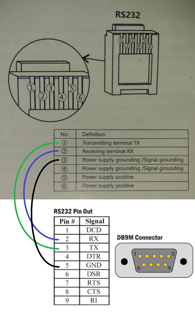
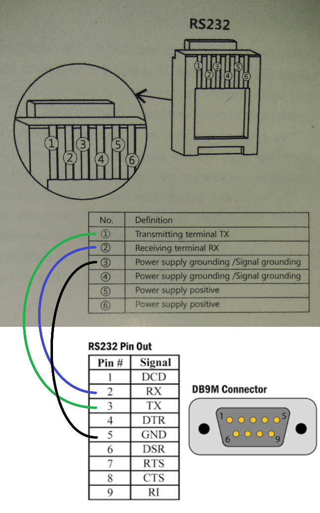 waxen hawk
north stream
It's not really RJ12, it just uses the same connector as RJ12 does (which is the...
waxen hawk
north stream
It's not really RJ12, it just uses the same connector as RJ12 does (which is the...
ah, i see. Still, is there a connector in the market that can handle rs232 communication but has rj45 wiring
north stream
The RJ45 connector is 8P8C and won't fit
waxen hawk
rip. is there any commercial adaptors or do I got to make my own i guess?
lol am i forced to buy their bluetooth module
cedar mountain
I mean, you can just buy an RJ12 cable and cut it open to get at the wires.
waxen hawk
cedar mountain
I mean, you can just buy an RJ12 cable and cut it open to get at the wires.
yep that sounds like the case
north stream
I wouldn't expect to find an off-the-shelf one with the correct pinout. Radio Shack used to sell some nice configurable ones.