#help-with-arduino
1 messages · Page 100 of 1
 livid osprey
 rocky schooner
1 000 000 micro seconds == 1 000 milli seconds == 1 second, right?
livid osprey
Yes
rocky schooner
Ok. I need it to chatch whether a toggle button bounced or not. How far are bounces away from each other?
I want to do denouncing in software
livid osprey
Depends on the button, but generally in the range of <20ms? I think debounce on gaming mice is usually set to somewhere between 4 and 10ms, but larger switches could have longer bounces...
rocky schooner
I tested it. Unwanted pushes took usually 40 to 80 milliseconds. I will just say you have to be slower than 100ms pause => no more than 10 pushes per second
 gloomy sandal
hey,
i need some help. i built an arduino leonardo clone and wanted to program the bootloader with an arduino uno but every time i get the message "Expected signature for ATmega32U4 is 1E 95 87". can someone help me to burn the bootloader?
 rotund kiln
Hello!
I'm trying to flash a D1 mini board and am running into difficulties. I feel like it's a bitrate issue, but cant find documentation on what to set it to.
I've tried a few different flashing apps, all of them time out. I tried opening a serial connection with Putty, and get a pile of gibberish.
Any thoughts/noob level troubleshooting tips?
 north stream
gloomy sandal
hey,
i need some help. i built an arduino leonardo clone and wanted to program t...
north stream
gloomy sandal
hey,
i need some help. i built an arduino leonardo clone and wanted to program t...
Usually that message gives the signature it received as well. If it's close to the same number, it may be a different chip variant (like the "B" version with an extra UART). If it's something like 00 00 00 or ff ff ff, then you have a connection problem.
north stream
rotund kiln
Hello!
I'm trying to flash a D1 mini board and am running into difficulties. ...
That does sound like a bit rate issue. The common ones are 115200, 38400, 19200, and 9600. If you're getting a lot of characters with repeated 0 or 1 like x (01111000) and ~ (01111110), then your receiving rate is likely too high.
gloomy sandal
does anyone know how to burn the bootloader onto an atmega32u4?
rotund kiln
Ive tried 15200, 19200, 14400 and 9600 (made sure to change my driver bitrate too) the output is just gibberish unicode characters, lots of s's, it looks like it's repeating in a loop
north stream
gloomy sandal
does anyone know how to burn the bootloader onto an atmega32u4?
I normally use a programmer pod, but there's a way to do it with an Arduino.
north stream
rotund kiln
Ive tried 15200, 19200, 14400 and 9600 (made sure to change my driver bitrate to...
You could try using a scope, or seeing if the signal is inverted, or maybe write some Arduino code to loop through a bunch of speeds one after the other.
rotund kiln
Thanks! I'll see what I can figure out
 stone stone
I have a bug in my Arduino code, and i cannot figure out what is causing the failure
I am running a Adafruit Feather RP2040.
im trying to make the Board Neopixel flash for debugging purposes. I am unable to get the light to function, based on the documentation, pin 27 is the proper pin to utilize the neopixel. but i could be wrong? i dont have a good understanding of Neopixel objects or functions. i couldnt find descriptions
code is shown bellow
Adafruit_NeoPixel pixel_Strip(6, 12, NEO_GRBW + NEO_KHZ800);
Adafruit_NeoPixel board_Pixel(1,27, NEO_GRB + NEO_KHZ800);

void setup() {
#if defined(__AVR_ATtiny85__) && (F_CPU == 16000000)
  clock_prescale_set(clock_div_1);
#endif
  pixel_Strip.begin();
  board_Pixel.begin();
}


void loop() {
   pixel_Strip.clear(); // Only needed to zero out pixel sets
   board_Pixel.clear();
   board_Pixel.setPixelColor(0,board_Pixel.Color(0, 100, 0));
   board_Pixel.show();

  delay(DELAYVAL);
      for (int i = 0; i < NUMPIXELS; i++) {
        pixel_Strip.setPixelColor(i, pixel_Strip.Color(100,0,100, 0));
      pixel_Strip.show();
      }
  delay(DELAYVAL);
}
 broken viper
stone stone
I have a bug in my Arduino code, and i cannot figure out what is causing the fai...
broken viper
stone stone
I have a bug in my Arduino code, and i cannot figure out what is causing the fai...
You forgot to import the library.....
stone stone
my apologies, i did import the library, i just gutted out all irrelevant code from my display here
broken viper
Mmmm
stone stone
i just read a few minutes ago, that you apearently should not run .show() for multiple pixel groups
assuming i understand whats going on
the reelvant code to trigger the Board Neopixel in Python is board.NEOPIXEL
however, im... not a fan of python and have been having a hard time using it, so i swapped back to uno since its similar to C which i do know
it is possible that it is not included in the Uno libraries yet?
broken viper
stone stone
however, im... not a fan of python and have been having a hard time using it, so...
Yes, I like C as well
I don't know...
It should be
I've only worked with Neopixels in CP, so IDK
I'll look into it
stone stone
why thank you, thats very kind
im still blindly bumping around
ive bounced between Circuit python, found it hard to read, went back to Uno, only to painfully recall that most of adafruit is big on CiPy, so the support i get through uno, including libraries, not just people, is a fair bit more limited unforutnately
 solemn cliff
stone stone
I have a bug in my Arduino code, and i cannot figure out what is causing the fai...
solemn cliff
stone stone
I have a bug in my Arduino code, and i cannot figure out what is causing the fai...
isn't it 16 ?
 stone stone
! perhaps i dont understand how these boards work, i thought the pixel was on PIN27 based on what i read?

GP16. general Pin 16?
well now i feel just silly!
that tracks based on the other pins i see yhere
solemn cliff
it's the GPIO number as the key says
stone stone
thank you very much. im still learning uh basic terms
solemn cliff
there's a lot of numbers on this pinout card, it's a little confusing 😛
stone stone
to clarify this is my first project ever using electronics
stone stone
update, was not able to get the pin to output... anything
 brazen falcon
pin 27 refers to the physical pin number on the RP2040 chip itself
Though I have no real idea why it would be useful on this type of infographic and not a source of confusion
If I were trying to find that sort of information I'd go directly to the schematic not some user-friendly infographic.
stone stone
im very green
 crude heart
anyone seen any xinput controller sketches?
I could only fine one pretty specific one but I'm looking more for a general controller layout kind of thing
(it's probably time to learn to write my own.)
 stable forge
crude heart
anyone seen any xinput controller sketches?
stable forge
crude heart
anyone seen any xinput controller sketches?
Is it a regular HID device? We have support in CircuitPython for custom HID devices. I just wrote a guide: https://learn.adafruit.com/custom-hid-devices-in-circuitpython
crude heart
looking into it
yes HID I think, but on a pro micro clone
first time using an arduino too. I got the xinput library loaded just fine and sent a hello world "blinking a button"
having trouble reseting my pro micro though, but I'll cross that bridge once I have a full control sketch to send it
I'll look into circuitpy but I think xinput might be a specific thing I need to work out of the box with Steam.
 twilit hare
Good morning all. I'm working on an arduino library for an open source pcb... and I'm struggling to find the right IDE to use. Been alternating between VS Code and Notepad++... any suggestions?
north stream
I usually use vim or the Arduino IDE itself, but there are likely other good choices.
 leaden walrus
i use VS Code for arduino lib dev. to edit source. but i'll have an arduino ide session going at same time for actual testing.
the arduino ide will be loaded with some test sketch
twilit hare
leaden walrus
i use VS Code for arduino lib dev. to edit source. but i'll have an arduino ide ...
That's what I've been doing as well. Sounds like I'm on the right track.
leaden walrus
when it comes to the text editor part of the setup, totally up to you. try a bunch and see what you like.
 wheat crag
if you have a preferred IDE or text editor, you can also use the arduino IDE in external editor mode, then after editing, save the sketch with the text editor you use and upload the sketch from arduino as usual
 jolly valve
I really like VS Code with the Arduino extension, overall it works very well
 wise socket

Adafruit Learning System
How to add lots o' storage with microSD (and SD) cards
wise socket
wise socket
https://learn.adafruit.com/adafruit-micro-sd-breakout-board-card-tutorial/introd...
Can you connect this to an arduino nano cause in the instructions I noticed that it doesn't have a 13th pin
 cedar mountain
wise socket
Can you connect this to an arduino nano cause in the instructions I noticed that...
cedar mountain
wise socket
Can you connect this to an arduino nano cause in the instructions I noticed that...
Can you clarify what you mean by 13th pin? The SD breakout board only has 8 pins.
wise socket
 wise socket
cedar mountain
Can you clarify what you mean by 13th pin? The SD breakout board only has 8 pins...
wise socket
cedar mountain
Can you clarify what you mean by 13th pin? The SD breakout board only has 8 pins...
I think I have found the 13th pin on my nano I didn't see it before. My bad nvm thank you for your help
 quick hornet
Long shot, but does anyone know if there is an arduino library to decode CAN-BUS messages using a CAN database file?
north stream
This one may not do exactly what you're looking for, but might be useful. https://github.com/sparkfun/SparkFun_CAN-Bus_Arduino_Library/archive/master.zip
 round creek
I have used the library arduino-mcp2515 for CAN with decent success, and then writing my own set of functions for decoding messages
quick hornet
I will be reading in many different CAN-BUS packets. I am working to replace code that previously ran on a Raspberry Pi. That had a python library cantools that could load a DBC file and then decode the canbus packets into key value pairs.
I figured I'd have to make something custom to load DBC files from an SD card on the Teensy 4.1. My current plan is to figure how the python library decodes the packets and write similar code in C.
 sonic pond
i have this https://www.spirithalloween.com/product/universal-step-pad-activator/45484.uts and want to detect it with an arduino. it seems its a simple piezo sensor and i was testing it with my multimeter and saw the voltage would go positive when pressed and negative for a second when released. my concern is that i understand the negative voltage can damage the arduino through the analog pin. i saw this example https://www.arduino.cc/en/Tutorial/BuiltInExamples/Knock and see the mention about the 1 megaohm resistor to protect the input. is that all i need to protect against these negative voltages?
north stream
I'll often use a large resistor (to limit current) and a zener diode (to limit voltage), but there are protection diodes within the Arduino as well. Piezo sensors can produce fairly high voltage in some circumstances, so I tend to lean toward extra protection.
sonic pond
Seems like it doesn't output more than around +/- 5v, even with all my weight jumping on it. So I'm mostly concerned with the negative voltages.
 hollow flint
hi all: I have an application where I need to switch a pin, on the fly, between an analog output and an input (I just need the high impedance). On my metroM4 I can start the program as the input, but once I call analogWrite(A0,val) I can't pinMode(A0, INPUT); and get back to an input.
 rough torrent
I'm purely guessing but maybe you need to analogWrite(A0, 0); or digitalWrite(A0, LOW); before setting it back to input???
hollow flint
@rough torrent thx but I can't ground it. it needs to float.
let me see if that works and it's real fast (tm)
rough torrent
Also, how are you determining that pinMode(A0, INPUT); is failing - the digitalRead isn't returning expected values??? If I recall correctly if you set a pin HIGH and change it to an INPUT it will still put out HIGH.
hollow flint
I'm trying to avoid pull up. I'm recording the trace. will share after I test.
yeah, it's staying in the last analogWrite state even if I try to digitalWrite low.
got it
don't use pinMode() at all
just go straight to analogRead()
rough torrent
I believe analogRead() will call pinMode by itself too
hollow flint
if I call pinMode at all it doesn't go to input. I need to give it a lone analogRead
north stream
It you want real fast, you're probably better off doing port manipulations than using the wrapper functions like analogRead() and pinMode()
hollow flint
yes, but I've shaved enough yaks for today
in case you want to know why I'd need this sort of functionality: https://github.com/dansteingart/duestat

GitHub
New potestionstat interface. Contribute to dansteingart/duestat development by creating an account on GitHub.
ok one more question
for the metro M4 is this already enabled to ~7 mA? https://github.com/arduino/ArduinoCore-samd/issues/158

GitHub
Moved from arduino/Arduino#5258 Originally reported by @MLXXXp The documentation for the Zero and MKR1000 both state: DC Current per I/O Pin 7 mA However, according to the ATSAMD21G18 datasheet, th...
and if so does it apply to the DACs?
 summer charm
For the life of me I cannot figure out how to install boards into the arduino IDE on Ubuntu 20.04, does anyone know?
 elder spruce
Hello,
I am using the Adafruit Neotrellis M4 Express running John Parks's Classic MIDI Synth Controller sketch. Everything will be working as expected when suddenly it will become unresponsive and the normally purple led will turn red. If I unplug it and power it back up, it relaunches with the red led again and does not function. It will not work until I plug it back into the Arduino IDE and reload the code onto it.
Any idea what is happening here/how I can avoid this from happening?
north stream
hollow flint
and if so does it apply to the DACs?
I would not recommend hooking a low impedance load to the DAC outputs if you want to maintain accuracy anyway.
 nimble finch
Hi everyone!!! 
I have a little question:
In a project, I am using a rotary encoder and it has a switch built in. When I press it once, the arduino believes that I pushed 2 or even 3 times. Sometimes it works fine, but only some hahaha. How can I solve this?? Thank you very much!
livid osprey
nimble finch
Hi everyone!!! <:gus:342384086477701120>
I have a little question:
In a project...

Open-source electronic prototyping platform enabling users to create interactive electronic objects.
stone stone
@livid osprey here is a copy of some of the code im running with atm, and the error.

im going go go ahead and define the two pins im using for serial usage now
 green thunder
Why not use the hardware serial?
stone stone
i could swap back to hardware serial. will Pins 6 and 5 on a FeatherRP2040 work for that job, will there be any additional interference with performance for doing so?
livid osprey
I don’t recall the pin out of the feather rp2040
stone stone
i can post it shortly
livid osprey
But rp2040 doesn’t use software serial.h
green thunder
Hardware serial has to be on 0 and 1
stone stone
green thunder
(I use the Philhower core also, if that matters)
livid osprey
‘#include "stdio.h"
#include "pico/stdlib.h"
#include "hardware/uart.h”’
stone stone
Current wire diagram for my project

i did drop one of the Miniboosts, but thats a minor change
nimble finch
livid osprey
https://www.arduino.cc/en/Tutorial/BuiltInExamples/Debounce/
Thanks, now it works flawlessly 🙃
stone stone
i was told i couldnt use the RP2040 RX and TX for the DF player?
perhaps that person was talking out their butt?
livid osprey
Serial2 in philhower core is defined as gp8 (pin 6) and gp9 (pin 9)
green thunder
Why? That doesn't sound right.
livid osprey
stone stone
perhaps that person was talking out their butt?
It may just be out of context, but that sounds totally baseless and incorrect…
green thunder
I can't right now, sorry
stone stone
fair
ok. so when i first started, i had the Board TX -> RX and board RX -TX
but i was told htat wiring was way off and wouldnt work
it seemed oubvious right?
livid osprey
I don’t understand why someone would say that wouldn’t work, but go on.
stone stone
i got told to move the TX RX to a digital set of pins, so i did
green thunder
As far as I can tell, you should be able to use HW serial. On the feather rp2040, that's GPIO 0 and 1 (don't remember the feather pin names). And yeah, you wire TX-> RX and vice versa
stone stone
well brilliant then. and id declare Hardware serial to use those two pins properly yeah?
green thunder
Can't remember the header name, but yeah, include the arduino non-software serial header, and then setup with Serial1.begin(115200);
stone stone
ty
one additional thing, i recognize my RP2040 is a self contained system, but is it possible for it to read back activities through the USB for debuggin purposes?
the original code here that im adjusting has Serial.println(F("messages"); in it, and that would be supremely useful for future projects, esp as this one gets more complicated
green thunder
You can communicate with your PC over the USB port using Serial. In fact, in the arduino terminal window, you can send strings over to your microcontroller by typing them into the text box at the top.
stone stone
thats beautiful. DEBUGGIN MODE HIYOOOO
green thunder
You can also write scripts on your PC (for example in Python) to do more complex serial comms
if I recall correctly I was able to send 63 bytes max per string using terminal text input
stone stone
most of my current project goals are self contained non delaying light and sound props with switch control. so for now, advanced cross communication is not super important. but knowing where my code breaks down is!
Serial isnt part of the SoftwareSerial.h package? the one i cant use?
green thunder
You don't need SoftwareSerial at all
stone stone
oh good.
well im swapping out softwareserial for hardwareserial so i can use RX and TX to control the DF player
green thunder
On the RP2040, Serial and Serial1 are already defined for you 😄
for Serial1 just wire up your other serial device to the RX/TX pins and you're good to go
stone stone
ok, im going to made the written adjustments here, afterward, i will ask for a quick code review?
green thunder
I may not be able to look at it right away (dinner on the way 🥩) but I can try to look at it later
livid osprey
Honestly, earl philehower core defines serial2 as well…
green thunder
Though the pins are mapped to dummies, so it's not really usable
(for the Feather anyway)
livid osprey
Serial is usb, serial1 is gp0 and gp1, and serial2 is gp8 and gp9. If you need more, there are libraries for creating more serial ports as well
green thunder
Nice
livid osprey
Serial2? Pins are mapped to 6 and 9…
green thunder
Oh I looked at the pins header in the feather variant awhile ago and could've sworn they were mapped to 31
stone stone
ive moved my Board -> DF player wires
based on what you said about RX and TX being perfectly suited for this job (which frees up pin 6 and 8)
so ive moved over to GP01, GP02 (TX and RX on the 2040)
ive added the hardwareSerial to header now. ok all i need now is to know how to translate Baudrate information. because ima level with you, ive seen baud rate a lot in my 3d printing stuff, and i have NO CLUE what any of it means. but best guess is some sort of communication speed protocol
livid osprey
You would be correct.
stone stone
yay for learning through osmosis. as much as you can commit to osmosis through a brick for a brain 🙂
did i label 6-9 right?
on lines 16 and 17 it looks like they are defining BAUD rate through softwareserial (which im replacing)
so i assume for 8 and 9 id put 115200?
https://puu.sh/Igxx0/38ff6c8cce.png
 green thunder
livid osprey
Serial2? Pins are mapped to 6 and 9…
green thunder
livid osprey
Serial2? Pins are mapped to 6 and 9…
Hmm yeah okay yeah I remembered correctly. In the Philhower core version 1.9.5 the pins for serial 2 are defined as:
// Not pinned out
#define PIN_SERIAL2_TX (31u)
#define PIN_SERIAL2_RX (31u)
this Philhower Core... how does that tie into what im suing here with Arduino RP2040?
livid osprey
stone stone
did i label 6-9 right?
on lines 16 and 17 it looks like they are defining BAUD ...
Should be 0 and 1, not 2 and 3
stone stone
is it a different "package"?
stone stone
so dont need to define Serial values at all?
livid osprey
stone stone
this Philhower Core... how does that tie into what im suing here with Arduino RP...
It’s one of two “packages” available for arduino ide for rp2040-based boards.
livid osprey
stone stone
so dont need to define Serial values at all?
Nope
stone stone
alright. so i wont be defining RP2040 TX or RX. and i have them linked to their pairs across the DF player.
from here i just... run program?
no definitions ? no baudrates? nothin?
green thunder
livid osprey
Should be 0 and 1, not 2 and 3
Here's all the serial defines for the feather in the pins_arduino.h file:
// Serial
#define PIN_SERIAL1_TX (0u)
#define PIN_SERIAL1_RX (1u)

// Not pinned out
#define PIN_SERIAL2_TX (31u)
#define PIN_SERIAL2_RX (31u)
I guess the pins for Serial don't need to be defined here
stone stone
actually lines 16 and 17 probably will still be borked
stone stone
bugger.
green thunder
Also for what it's worth, there are definitely issues with some of the Philhower pinouts. I recently had to submit a fix to get both of the I2C ports working correctly on the ItsyBitsy
(Though Serial1 should be good to go 👍 )
livid osprey
Idk what the baud rate is on the music player, but you just match it.
stone stone
feather RP2040 is relatively new, so it explains a lot why there are so many.. missing items that are making my life... difficult
aside from being greener then a tree borne banana
green thunder
Yeah I've been playing with it a lot the last few weeks (particularly the feather and the qt py) so some of these issues are still pretty fresh on my mind lol
stone stone

ok, rewired TX RX to their pairs on the DF player
added 1k resistors as advised to both pins beforehand
stone stone
livid osprey
Idk what the baud rate is on the music player, but you just match it.
mySoftwareSerial.begin(9600);
Serial.begin(115200);
^ from the sample code orginal
do i just say
myHardwareSerial.begin(9600);
serial1.begin(115200) ;
serial2.begin(115200)
assuming i understand whats going on...
green thunder
all you need is:
Serial.begin(115200); // If you want to talk to your PC over USB serial)
Serial1.begin(115200); // To talk to your DF player
id def like to do that
green thunder
that's assuming that 115200 is the baud rate that the DF player uses
stone stone
it is
ok. time to tell the little machine of metal and energy the magic words so it talks to me...
magic machine talks at 9600
Failed to work
says
serial1.begin(9600);
Serial.begin(115200);
are softwareSerial commands, which dont work on the RP2040 from what i can see
so i have to swap those two out somehow
livid osprey
‘#include "stdio.h"
#include "pico/stdlib.h"
#include "hardware/uart.h”’
Try these instead of softwareserial.h
 pine bramble
Anyone have experience with the AFBNO085? I keep getting this error when using the quaternion_yaw_pitch_roll example. I'm just connecting it using the qwiic connector. First it randomly resets and then it won't reconnect when resetting the microcontroller board
 stone stone
livid osprey
‘#include "stdio.h"
#include "pico/stdlib.h"
#include "hardware/uart.h”’
stone stone
livid osprey
‘#include "stdio.h"
#include "pico/stdlib.h"
#include "hardware/uart.h”’
going to try this shortly
 fringe shard
Hi I'm working with Justin Trouble Again and im trying to help him with these serial issues.
I'm reading the arduino-pico docs and I see Serial is the USB serial port, and while Serial.begin() does allow specifying a baud rate, this rate is ignored since it is USB-based. (Also be aware that this USB Serial port is responsible for resetting the RP2040 during the upload process, following the Arduino standard of 1200bps = reset to bootloader).
So it completely ignores the baud rate
livid osprey
fringe shard
I'm reading the arduino-pico docs and I see ```Serial is the USB serial port, an...
Today I learned.
Probably still need a baud rate for Serial1 though.
fringe shard
Yea
From what i understand
I can create a UART on Serial2
For printing ot the serial monitor
But the Serial itself doesnt do that
green thunder
Can you adjust the baud rate of the DF Player to 115200?
livid osprey
I doubt it
green thunder
And yeah that does ring a bell, I think the baud rate you pass in to begin is ignored on most non-avr architectures
though I've not had issues using the hardware serial to communicate with lower baud rates 🤔
stone stone
me and Fane are in voice chat discussing this and watching me code it up
let me know if you would like to join us
stone stone
green thunder
Can you adjust the baud rate of the DF Player to 115200?
DF player has a baud rate of 9600 based on the sample code
livid osprey
As appreciative of you guys for the invitation, I'll pass for now. While I do try to make myself available for assistance, I usually try to help people get over larger hurdles as a reference, rather than get involved with all the details and development.
If you get stuck, feel free to reach out!
green thunder
Yeah I'm kind of in the same boat. At this point, if there's no way to adjust the rate of the DF player itself (i see references here and there of things saying it's possible, but nothing that says how), and if it won't work with the RP2040, then this will definitely be a bit of a hairy one to solve
stone stone
if it doesnt work with the RP2040 ill have to swap out boards :/
or finally embrace CPy, since you can run Mp3s right off of the rp2040
green thunder
Might be the case, if your only options are arduino + DF player
livid osprey
RP2040 can't run at 9600?
stone stone
it cant? x.x?
green thunder
I'm looking at the Philhower core, and as far as I can tell you should be able to actually 🤔
all you should need to do then is change Serial1.begin(115200); to Serial1.begin(9600);
You might not be able to change the baud rate for the USB serial, but you should absolutely be able to for Serial1
green thunder
To be fair I've had a bit of a hard time following along lol. Here's what I can tell from the code: @fringe shard is correct that for the USB serial connection (i.e. Serial in Arduino) on RP2040, the baud rate passed to begin is indeed ignored:
void SerialUSB::begin(unsigned long baud) {
    (void) baud; //ignored

    if (_running) {
        return;
    }

    _running = true;
}
However, we're concerned with Serial1 here, and that's a different story: it uses SerialUART, not SerialUSB
And the implementation for SerialUART is not empty. Thus, I concluded you should be able to set Serial1 to 9600 bps, and it should be able to work with the DF Player.
stone stone
should x.x
livid osprey
I’d be surprised if it didn’t
stone stone
ive been at the sound part for six hours or so now
and im not making much progress at all. im frustrated friends.
livid osprey
Have you established a serial connection yet?
stone stone
in regards to board - PC communications?
livid osprey
Board to dfplayer
livid osprey
Is it wired to your amplifier and speaker?
stone stone
OH HECK
I JUST WIRED IT TO MY 5V INTAKE POWER AND NOW I GOT A RED LIGHT ON THE DF PLAYER
livid osprey
Relax
livid osprey
6 hours for audio, huh?
Maybe I should pop into this voice call or whatever...
That's an awfully long time for one component.
stone stone
i know, im sorry. im .. not very smart, i just work really hard
and i hate needing so much help
livid osprey
No it's fine, it's not exactly the easiest thing to do, and most people would've given up faster than you did
Help is always okay to ask for
stone stone
it just eats a lot of time and patience from people
livid osprey
Do you need more help?
livid osprey
So your goal is to get pewpew sounds out of your speakers.
You have all of the hardware components?
stone stone
Yes, bare minimum. i have crab rave installed so i can hear that and know its working lol
i have a feather RP2040 headered up, a DF player. amplifier is available if required, i also have several kinds of speakers
as is a mini booster
livid osprey
Okay, so what is your current roadblock?
stone stone
no sound emission. i think having com4 port communicate back println would be helpful, but i have not had success there
so perhaps the first goal should be feather-pc communication?
stone stone
none. confirmed voltage through aligators however
livid osprey
But you can hear crab rave?
Oh nvm
So you have crabrave.mp3 and you're trying to hear it.
livid osprey
I would wire up your amplifier and speaker to make sure you can hear your result, since I'm not sure your bare boards can handle the low resistance of a single speaker.
But if you want to start with USB serial, we can start there.
stone stone
that seems advisable.
afterward i can route the DF player to the class D audio amp (PAM8503 i believe)
stone stone
i have
Serial.begin(115200);
    Serial.println();
    Serial.println(F("DFRobot DFPlayer Mini Demo"));
    Serial.println(F("Initializing DFPlayer ... (May take 3~5 seconds)"));
Does your serial monitor receive any data?
stone stone
Com port 4 opens serial port, no data files away though
Confirming we now have sound
im just getting a rapid beep noise though
no feed from serial port though
livid osprey
Can you try removing the F(...)? I think that's specific to AVR.
stone stone
ok
livid osprey
RP2040 doesn't need that IIRC
green thunder
Shouldn't hurt though
north stream
Maybe add a delay before the first print too
green thunder
Oh yeah good point
It seems to take some time on RP2040 for the USB serial port to be ready

 green thunder
I think you need to remove the
Serial1.setRX(3);
Serial1.setTX(2);
lines
Those aren't the correct pins, and Serial1 should already be using the correct pins without having to call setRX and setTX
stone stone
disabled serial 1, successfully acheived USB communication. https://puu.sh/IgyXv/2b7f6f53ad.png

we have made progress
livid osprey
Wait, so serial1 is completely disabled?
Or did you just remove the setRX/TX commands?
stone stone
livid osprey
Or did you just remove the setRX/TX commands?
disabled SetRX and TX
stone stone
minor positive, have consistent mini jackhammer noise from DFplayer
i assume this is due to lacking power needed to play?
livid osprey
Might be an impedance issue, let's just move onto the amplifier+speaker configuration
YEah power might be insufficient to drive the speaker
stone stone
moment, serial port communication isnt working any more
livid osprey
Are you uploading code?
 livid osprey
Odd. USB serial ports have done weirder things before though, so let's turn our attention to sound first
stone stone
additional notes: we have semi success with USB communication now. good.
the speaker makes a mini jackhammer noise consistently from the moment it is plugged into the device
but yes, lets move on to sound
i have a class D audio amplifer here.. but im uncertain how to wire it through the DF player
Vin and Gnd seem self explanatory atleast. A and A- along with SD are not as much

This super small mono amplifier is surprisingly powerful - able to deliver up to 2.5 Watts into 4-8 ohm impedance speakers. Inside the miniature chip is a class D controller, able to run ...
livid osprey
Try A+ to DAC_L and A- to GND
livid osprey
No?
green thunder
Shouldn't need to
stone stone
ok. good to know. theres no additional software behavior, only electrical
livid osprey
Your DFPlayer is already trying to play music, we're just giving it some hardware on its outputs
stone stone

White is ground in this case
Normally I'd use black but my neopixel strip used white for ground so I've kept consistency
Oh and for reference here is my feather

im not pluggin this in until i get a green light lol
stone stone
Yeer
Bruh you arnt going to beleive this, but my speakers are picking up extremely garbled radio signals like you would from an untuned fm or am radio
I have to hold it to my ear to hear, but it's kinda wild
livid osprey
Hm?
stone stone
I'm serious.
fringe shard
that can happen from poor insulation I think
I know guitar amps can have that issue
stone stone
However. It's 11pm my time, so I'm hanging this up till tomorrow
Oh fane, we succeeded with serial connection and message postinf
fringe shard
i saw
livid osprey
Aight, I looked at the schematic for the dfplayer, and I think you need a resistor to connect dac_L to the amplifier. In fact, the internal wiring on the dfplayer seems to wire both l and r through a pair of 22k resistors to the onboard amplifier.
Get some rest. Feel free to ping me tomorrow when you’re ready to experiment further…
stone stone
livid osprey
Aight, I looked at the schematic for the dfplayer, and I think you need a resist...
Thank you for your time and patience
 errant totem
Hey can anyone point me in the direction for reading how to get a esp to send a HTTP post to a url based on a sensor or a pin state. In the simplest possible way.
I have found a web based api tester to send code to an app. I just don't know the best way to implement it and so far reading I have just gotten confused with people outlining much more complicated projects.
This is what I'm using it for at the moment, beer 😌
https://docs.brewfather.app/integrations/custom-stream
 livid osprey
errant totem
Hey can anyone point me in the direction for reading how to get a esp to send a ...
livid osprey
errant totem
Hey can anyone point me in the direction for reading how to get a esp to send a ...
I used the tutorials on this site to learn how to use an ESP32, see if this might help. https://randomnerdtutorials.com/esp32-http-get-post-arduino/
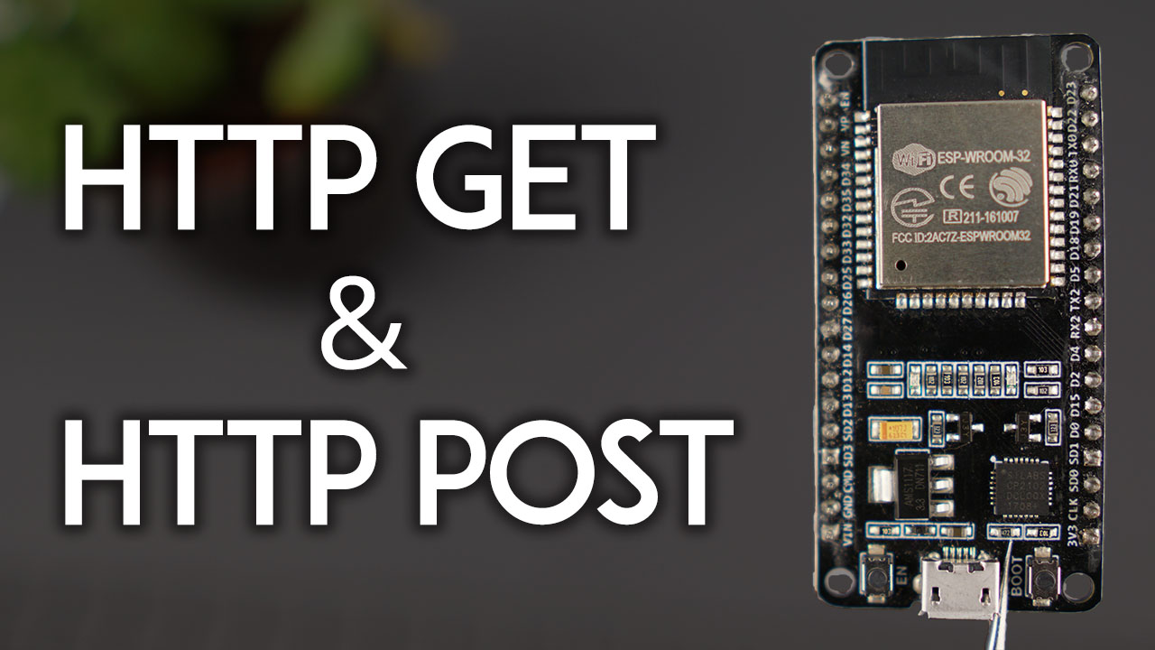
Learn how to make HTTP GET and HTTP POST Requests with the ESP32 board with Arduino IDE. How to get values, post JSON data objects, URL encoded requests, etc.
errant totem
Thanks @livid osprey
stone stone
"fully supports FAT16 , FAT32 file system, maximum support 32G of the TF card, support 32G of U disk, 64M bytes NORFLASH"
is there any chance my SD card is wonk?
livid osprey
Yes, but unless you have a physical crack down the middle, it's usually salvageable with a reformat.
What kind of SD are you using?
stone stone
micro SD 128MB
livid osprey
Reformat as a FAT16 (or FAT) and try again?
stone stone
sounds decent
lol what kinda code bug is this? https://puu.sh/IgF8A/fd6001cb62.png

my loopCounter increment is killing the first letter every loop

cute, but like, what
livid osprey
Haha, the plus sign does weird things when you try to add two different types.
livid osprey
Either cast loopCounter to String or put it in its own print() after.
livid osprey
Nope
stone stone
im going to be reassembling the debug code that the example had that used the softwareSerial to Hardware serial
stone stone
great, ill take a photo of my layout for you in a few.
i have
stone stone
i added 1k Resistors to the Feather -> DF RX and TX connections
livid osprey
Do you have any larger resistors?
The internal amp used 22k, so you probably want to aim for at least 10k
stone stone
i should have some, but not at my day job desk
im currently multitasking
oh dear. it appears to be constructed a bit different here in C/Cpp then in C#
https://puu.sh/IgFmm/9e4452bc6c.png
 livid osprey
You could also try Serial.printf("Loop Counter: %u \n", loopCounter);
This used to be the standard way to get other datatypes into strings back in the old days of C haha
%u indicates an unsigned integer, and takes the corresponding variable argument in the function and inserts it into the string before printing it to your console.
stone stone
i was about to ask what that part meant. if memory serves \n is new line
stone stone
programing is magic filled with an endless number of magic words and incantations.
or it atleast fels that way to me lol
debugging has yielded results
https://puu.sh/IgFuF/ece37539b0.png
 green thunder
String handling in C is a nightmare frankly 😩
stone stone
i can live with the counter issue, i am however, rather frustrated by the failure of the DF player
based on the debugger, it isnt properly being assigned to the Serial1?
livid osprey
You might need some time between starting serial1 and starting myDFPlayer. Try adding a delay or a while(!Serial1);?
stone stone
got it, will do!
stone stone
your printline code worked btw! thank you
also update
every time the hardware attempts to link into the DFPlayer i get two pulses from the speaker before we reloop
https://puu.sh/IgG1k/5630c0942e.png

i put a 1 second pause in to check
so it goes "attempt to connect" Boop boop
attempt to connect Boop Boop...
ad infintium
id hope that means my wire layout is atleast correct
@livid osprey ... so in your opinion, should we give up, and swap to Cpy .mp3 player and systems? i dont think im smart enough to figure this out, and those that are able to reed through this likely wouldnt want to bother
livid osprey
Send another pic of your wiring?


 livid osprey
What kind of serial resistors are you using?
stone stone
1ks there
livid osprey
take em out?
Usually if you add resistors at all, they're <100ohms
Try direct connection without the resistors and see if you get serial
stone stone
will do
i also realized at 3.3v im probably at the lower end of what can run on this
still getting the two pulses per second situation
livid osprey
OH
Right, the amplifier can draw some current too. If you have a multimeter, you should check that voltage...
stone stone
i have a hair brained idea
im going to pass the power through a mini booster to raise us up to 5v in
if this is just a voltage problem, that may solve it
im getting a consistent whining noise at 5v, along with the "boop boop" now
so its a lot louder atleast lol
 stone stone
no, says attempting to connect and failing the pass attempt.
assuming my code is working as its supposed to

for reference
im going to draw up a wire diagram to make things easier to follow as well
i need to eat lunch bbs
livid osprey
while(Serial1.available()>0) {
    Serial.print(Serial1.read());
}```
Okay, insert this snippet into your other while loop when you get a chance.finished eating and drew up a quick circuit diagram https://puu.sh/IgHLs/03bdbd55a3.png

got a work meeting so wont be available for a bit


 fiery horizon
Does anyone happen to know what the button pin is for the on board button for the Adafruit Glasses Driver Board?
nevermind, I figured out it's pin 4 lol
 frank meadow
Hi guys, I have a feather M4 express and am trying to program it, but the feather won't show up as a drive or on the arduino IDE. I'm on MacOS 15.4. would anyone be able to help me?
And the cable I'm using can transfer data
couldn't find a feather channel but im assuming this channel is all good
frank meadow
just tried on a windows PC with a different cable and still had no luck? anyone know of anything i might need to do for it to work?
pine bramble
frank meadow
just tried on a windows PC with a different cable and still had no luck? anyone ...
https://learn.adafruit.com/adafruit-feather-m4-express-atsamd51/setup let me know if you still need help

Adafruit Learning System
This Feather is fast like a swift, smart like an owl, strong like a ox-bird
frank meadow
That’s the issue, I can’t get it to show up in either the arduino ide or as a removable drive, even through check device manager, I have tried multiple cables too and I’ve tried on a windows pc and a mac
I’ve installed all the relevant software for the board on both OS's (or at least i think)
pine bramble
Did you enter the url for the board manager?
Then install the board specific software?
I did it with a Mac just yesterday following those instructions
It’s weird that it doesn’t show up. Does it get power? Like does the LED light up?
frank meadow
yup gets power, neopixel is green that slowly flashes/dimms
when i enter bootloader mode the neopixel goes red
tried multiple cables with it
pine bramble
Can you send a screenshot of your boards tab under tools?
pine bramble
Yeah board manager or whatever it’s called
pine bramble
Ah. Don’t have any experience with that
frank meadow
uhh i can't filter by installed
hang on
I've got the default boards, the Arduino SAMD boards, and the adafruit SAMD boards
pine bramble
Yeah I had that too. Once you try to upload a program try spamming the reboot button and upload again
Not sure why that worked
The port eventually shows up
Or at least it did for me
Maybe you can try on Mac?
For windows have you tried installing the CH340 drivers?
frank meadow
pine bramble
Maybe you can try on Mac?
same stuff installed, shows an irrelevant port (bluetooth)
pine bramble
For windows it might work? https://forum.arduino.cc/t/port-grayed-out-under-tools-port/408689/8
Arduino Forum
@asrz900 Try the steps below: Step 1: Please try the steps below via the IDE: · Tools > Board > Boards Manager · Search for "Arduino AVR Boards" · From the drop-down menu select latest version · Click "Install/update" · Wait for installation to finish · Click "Close" and restart your IDE. See https://www.arduino.cc/en/Guide/Cores Note...
But I can only speak from the Mac perspective
Okay I managed to make it disappear from my ports as well. Only have Bluetooth again
Double clicking the boot button made it reappear
Going to try to recreate it again
frank meadow
yeah when i put it in boot mode i get a red light, and the board isn't detected at all, not even as a USB
like before
have considered the possibility of it not being a good board, I got it off ebay since adafruit doesn't ship where i live
pine bramble

This is all I got
Sorry I can’t help more than that
Not sure if any of the other settings matter
Maybe others can help you more tomorrow. Good luck!
frank meadow
thanks a bunch man
stable forge
frank meadow
thanks a bunch man
If you double-click the reset button, does FEATHERBOOT show up as a drive? The red LED (not the NeoPixel) next to the USB socket should pulse slowly (about once a second). If it pulses quickly, then the board is not seeing a USB connection.
frank meadow
stable forge
If you double-click the reset button, does FEATHERBOOT show up as a drive? The r...
it's solid red
wait sorry wrong thing
I'll check in a few minutes sorry
stable forge

 brave maple
with arduino and a pair of Adafruit Neopixel Neomatrices, how would you get the arduino to display a pair of simple animated eyes (literally just 2 circles animated to blink at random)? I've gotten my code to have the matrices be in a tiled format thanks to basing it off of the example tile code provided in Arduino's example libraries
I've been looking for a good tutorial but have yet to find one that explains what to do
livid osprey
brave maple
I've been looking for a good tutorial but have yet to find one that explains wha...
Something like this? https://learn.adafruit.com/animating-multiple-led-backpacks/software

It's not quite the same thing, so there may be some minor adjustments here or there...
brave maple
livid osprey
Something like this? https://learn.adafruit.com/animating-multiple-led-backpacks...
I've tried looking at that one but struggled to understand how to incorporate it into NeoMatrices since I'm not working with their LED backpacks
I don't know if it'll not work if I don't include #include "Adafruit_LEDBackpack.h"
The code I currently have is slightly modified from one of the examples:
#include <Adafruit_NeoMatrix.h>
#include <Adafruit_NeoPixel.h>
#ifndef PSTR
 #define PSTR // Make Arduino Due happy
#endif

#define PIN 6

Adafruit_NeoMatrix matrix = Adafruit_NeoMatrix(16, 8, 3, 1, PIN,
  NEO_TILE_RIGHT  + NEO_TILE_LEFT   + NEO_TILE_COLUMNS   + NEO_TILE_PROGRESSIVE +
  NEO_MATRIX_RIGHT + NEO_MATRIX_LEFT + NEO_MATRIX_COLUMNS,
  NEO_GRB + NEO_KHZ800);

const uint16_t colors[] = {
  matrix.Color(255, 50, 0), matrix.Color(0, 255, 0), matrix.Color(0, 0, 255) };

void setup() {
  matrix.begin();
  matrix.setTextWrap(false);
  matrix.setBrightness(40);
  matrix.setTextColor(colors[0]);
}

int x    = matrix.width();
int pass = 0;

void loop() {
  matrix.fillScreen(0);
  matrix.setCursor(x, 0);
  matrix.print(F("0"));
  if(--x < -36) {
    x = matrix.width();
    if(++pass >= 3) pass = 0;
    matrix.setTextColor(colors[pass]);
  }
  matrix.show();
  delay(100);
}```I think you'd be using neopixel.h and neomatrix.h instead
Oh
yeah that
The loop function is designed to marquee whatever text you put in the matrix.print(...); You would probably want to draw some eye bitmaps and switch between the bitmaps
brave maple
Would I need the loop function if my plan is to have the two circles (one circle per matrix) be animated to randomly blink?
livid osprey
You would probably be rewriting it from scratch.
brave maple
okay; and to check, a bitmap would be this style of code?
{
  B00000000,
  B00111100,
  B01111110,
  B01111110,
  B01111110,
  B01111110,
  B01111110,
  B00111100
},{
  B00000000,
  B00111100,
  B01111110,
  B01111110,
  B01111110,
  B01111110,
  B01111110,
  B00111100
},{
  B00000000,
  B00111100,
  B01111110,
  B01111110,
  B01111110,
  B01111110,
  B01111110,
  B00111100
},{
  B00000000,
  B00000000,
  B01111110,
  B01111110,
  B01111110,
  B01111110,
  B01111110,
  B00111100
},{
  B00000000,
  B00000000,
  B00000000,
  B01111110,
  B01111110,
  B01111110,
  B01111110,
  B00111100
},{
  B00000000,
  B00000000,
  B00000000,
  B00000000,
  B01111110,
  B01111110,
  B01111110,
  B00111100
},{
  B00000000,
  B00000000,
  B00000000,
  B00000000,
  B00000000,
  B01111110,
  B01111110,
  B00111100
},{
  B00000000,
  B00000000,
  B00000000,
  B00000000,
  B00000000,
  B00000000,
  B01111110,
  B00111100
},{
  B00000000,
  B00000000,
  B00000000,
  B00000000,
  B00000000,
  B00000000,
  B00000000,
  B00111100
},{
  B00000000,
  B00000000,
  B00000000,
  B00000000,
  B00000000,
  B00000000,
  B00000000,
  B00000000
}};
const int IMAGES_LEN = sizeof(IMAGES)/8;```Yup
brave maple
okay; and the only included libraries i would need if I were to try again with the provided tutorial would be Adafruit_GFX.h, Adafruit_NeoMatrix.h, Adafruit_NeoPixel.h, and Wire.h?
livid osprey
Should be, as far as I recall
brave maple
okay 👍 I'll try again with the tutorial and see what I can accomplish from there^^ thank you!
okay, already running into some problems with trying to treat NeoMatrices the same way as the LED backpacks
Adafruit_8x8matrix matrix = Adafruit_8x8matrix(); Doesn't appear to work when I check it and neither does Adafruit_NeoMatrix matrix = Adafruit_NeoMatrix();
livid osprey
Nah, you should be keeping the same NeoMatrix constructor from the other demo.
Adafruit_Neomatrix() has a lot of args to properly define the matrix.
Adafruit_NeoMatrix matrix = Adafruit_NeoMatrix(16, 8, 3, 1, PIN,
  NEO_TILE_RIGHT  + NEO_TILE_LEFT   + NEO_TILE_COLUMNS   + NEO_TILE_PROGRESSIVE +
  NEO_MATRIX_RIGHT + NEO_MATRIX_LEFT + NEO_MATRIX_COLUMNS,
  NEO_GRB + NEO_KHZ800);
@brave maple
brave maple
@livid osprey okay 👍 those should still be in place
currently, I have
#include <Adafruit_NeoMatrix.h>
#include <Adafruit_NeoPixel.h>
#include <Wire.h>


#define PIN 6

Adafruit_NeoMatrix matrix = Adafruit_NeoMatrix(16, 8, 3, 1, PIN,
  NEO_TILE_RIGHT  + NEO_TILE_LEFT   + NEO_TILE_COLUMNS   + NEO_TILE_PROGRESSIVE +
 NEO_MATRIX_RIGHT + NEO_MATRIX_LEFT + NEO_MATRIX_COLUMNS,
 NEO_GRB + NEO_KHZ800);

const uint16_t colors[] = {
  matrix.Color(255, 50, 0)};

void setup() {
  matrix.begin();
  matrix.drawRect(0, 0, 8, 8);
  //matrix.setTextColor(colors[0]);
}```

It gives me an error when it checks the drawRect functionand reading the tutorial, I'm not exactly sure how to get it to recognize each matrix to draw a circle on each since the Adafruit_8x8matrix function doesn't work with NeoMatrixes
livid osprey
Oh, NeoMatrix only has drawPixel and fillScreen...
brave maple
aaaaah; im guessing that's why finding tutorials for them was such a long hunt then
would it be better to save up and switch to the LED backpacks for this project?
I'm using an Arduino Uno for the "brains" of this project
livid osprey
That's up to you. This is definitely doable with a neomatrix, but you'll have to utilize a different set of libraries to get to where you need. Adafruit_GFX should have the drawRect and related graphics primitives, I'm just not sure how to inherit it off the top of my head...
Ah, here we go. Take a look at this for reference: https://github.com/adafruit/Adafruit_NeoMatrix/tree/master/examples/MatrixGFXDemo

GitHub
Adafruit_GFX-compatible library for NeoPixel grids - Adafruit_NeoMatrix/examples/MatrixGFXDemo at master · adafruit/Adafruit_NeoMatrix
I don't know if there's a good tutorial to reference for this, but this example should have all the code snippets you need to accomplish your blinking eyes.
With some modifications, of course...
brave maple
Okay, I'll be sure to check it out 👍
livid osprey
Be sure to take your time, there's a LOT to digest in this example.
brave maple
I'll be sure to read, thank you^^
 burnt jackal
Hey
Does anyone by chance have an example of plugging a USB mouse into a pi pico using TinyUSB?
ultimately I want to convert a USB mouse to a Serial mouse for use on old PC's.
I know it can be done with a PS/2 mouse but getting a halfway decent PS/2 mouse today, is easier said than done.
 sinful saffron
Does anyone have a recommended chip to program an Atmega2560 ? Was looking at the FT232RL but that appears to be out of stock everywhere
 gilded swift
ch340g/c
gilded swift
sinful saffron
Does anyone have a recommended chip to program an Atmega2560 ? Was looking at t...
are you talking about the IC itself or a premade board?
sinful saffron
I plan on using the ISCP header to program the "Mega" from another Mega
and just upload programs via the UART
so, just the chip essentially though
gilded swift
WCH(Jiangsu Qin Heng) WCH(Jiangsu Qin Heng) CH340C US$0.7069
LCSC electronic components online Interface ICs USB ICs
- leaded datasheet+inventory and pricing
it's a painfully cheap USB to Serial chip
that one should omit the need for an external OSC
sinful saffron
I don't mind a little bit more pricey if it works with the Arduino IDE and does the reseting of the Atmega (if that's how it's needed to be done to upload a program)
gilded swift
the CH340C works with arduino
sinful saffron
basically trying to put a Mega on a custom board
gilded swift
most of the arduino clones use it
sinful saffron
gotcha
gilded swift
Arduino doesn't necessarily care if you're using an FT232R or a CH340, or whatever USB to Serial Chip
so long as it can see the COM port and get back responses from the MCU through the COM port
sinful saffron
does it not need to throw the reset pin high on the chip though?
in addition to the TX/RX
or is that part of the UART protocol
gilded swift
it's part of the payload that arduino sends to the USB to Serial adapter
but basically you'd hook up reset on the chip you want to program to the DTR pin of the CH340
sinful saffron
I was hoping to use a namebrand lol, but that could work. Was looking at how the FTDI chip was connected here: http://electronics-diy.com/FT232RL_USB_to_Serial_Adapter_for_PIC_AVR_ATMEGA_ARDUINO_MCUs.php
and gotcha, I see the DTR pin
gilded swift
FTDI are great but they are hard to come by. in fact I have 3 FT232H that i'm just sitting on because i'm afraid to ruin them with them being in short supply
and some FPGA chips that they are meant to program
sinful saffron
yeah, this chip shortage is crazy
gilded swift
yeah, i finished designing a hackable Bluetooth smart watch today and can't build it because the nRF52811 isn't available until April next year at the earliest
sinful saffron
like, oh, this chip works great (goes to look it up) not available
gilded swift
yeah, i'm just going to sit on the design till i can get the chips
sinful saffron
wonder if they have a solder-able version of the CP2102
gilded swift
not likely
it's probably just going to be some QFN package
which you could solder with a hot plate or a hot air gun
sinful saffron
haven't gotten to that stage of doing that quite yet
at least as reliably as hand soldering
gilded swift
it's all about having a good stencil and good paste
sinful saffron
true, though, I probably did the worst project possible to try it out on to begin with lol
some of the LEDs that were like 3mm across
melted the edges
not pretty
looks like more reading ahead but this chip might do it https://learn.sparkfun.com/tutorials/sparkfun-usb-uart-breakout-cy7c65213-hookup-guide/all

Mouser Electronics
gilded swift
Sparkfun also makes a CH340 breakout
sinful saffron
guess it's been pretty well tested then
gilded swift
Oh yes, there are people here that refuse to use FTDI chips due to “brick gate” that happened a number of years ago when FTDI started bricking illegal clones through a driver update
sinful saffron
yeah, not a fan of that either, I understand where they were coming from, but normal users didn't even know they were using clones half the time
seems like a lot companies are locking their chips down and using serial based locking and such
gilded swift
Yeah. I like FTDI for the consistency but I’m exploring new options with the chip shortage
sinful saffron
what about Cypress?
gilded swift
Never used their chips but I imagine they are fine
gilded swift
But if you want dirt cheap that works very well, CH340C
sinful saffron
just need one chip so it's all good either way, but thanks!
gilded swift
👍🏻
 prime nacelle
Anyone using Adafruit AHRS NXP library?
 leaden lynx
I am getting a strange error code when I try to upload code to my Circuit Playground BT:
Arduino: 1.8.16 (Windows 10), Board: "Adafruit Circuit Playground" : avrdude: butterfly_recv(): programmer is not responding
I don't have any problem uploading code to my UNO; and I have the right Port and Board selected; I have updated the IDE and libraries; and restarted my computer; and pulled out quite a bit of my own hair - but nothing seems to help. Does anyone have any advice for me?
stable forge
leaden lynx
I am getting a strange error code when I try to upload code to my Circuit Playgr...
Circuit Playground Bluefruit has a different micrcontroller chip. As I mentioned in #help-with-circuitpython, you need to download the Adafruit nRF52 board package and choose the CIrcuit Playground Bluefruit board.
leaden lynx
stable forge
Circuit Playground Bluefruit has a different micrcontroller chip. As I mentioned...
Ok - I downloaded those boards in the manager - but I only have the option of "Arduino Primo" and Adruino Primo Core - are these the same as the Circuit Playground BT?
stable forge
leaden lynx
Ok - I downloaded those boards in the manager - but I only have the option of "A...
You need this boards package:


Add this in the Preferences dialog if you haven't already (it's available for copying in the board guide)

Do the last thing first, then the Adafruit packages will show up
leaden lynx
stable forge
I think it is working! Thank you... I didn't have the correct board options!! Thank you
green thunder
For some reason I can't seem to use the LED glasses and the WiiChuck breakout board on the same I2C port 😢
stable forge
green thunder
For some reason I can't seem to use the LED glasses and the WiiChuck breakout bo...
hmm, are you supplying 5v or 3.3v on the VIN pin on the breakout?
green thunder
3.3v
I just managed to get it to work on the Feather RP2040, but it doesn't work unless I initialize the WiiChuck library first 🤔
I'm going to try and see if I have the same result on the nRF glasses driver
No dice there
Unfortunately I'm having a separate issue where Serial doesn't seem to work either on all of my nRF52840 MCUs which is making it hard to debug the issue lol
(Or maybe the issues are related? no idea)
stable forge
There have been some issues discussed in the forums: https://forums.adafruit.com/search.php?keywords=nunchuck
green thunder
stable forge
There have been some issues discussed in the forums: <https://forums.adafruit.co...
Ah thanks! I'll dig into this a bit more later, unfortunately I have to go now 😢
stable forge
your videos are great! I passed them on to other staff
green thunder
Oh thanks! 😮
 odd willow
Hello! Noob question here..
I have a 5V two pin ventilator and I simply want it to work 10 seconds and after that pause 10 seconds (in a loop). But I just can't find out how to make it work. Google isn't my friend either. Someone who can help me out with a simple code?
stable forge
The "Blink" example is very close to what you want. But is this a fan or some other power-hungry thing? You can't drive it directly from a pin, but you could use a transistor or relay to turn it on and off.
you want to do this in Arduino?
odd willow
It's a fan comparable to this one. I want to control it by arduino cause in the end it has to be a part of a larger project. But first I wanted to make the fan work. Do I understand it right that I need to give the fan an external power source?

(I hoped because it is a 5V fan it could get it's power directly from the arduino but I guess I was wrong?)
stable forge
depending on its current requirements, you could run it from the 5v pin, but you can't control it with a logic pin.
you can't run it directly from a logic pin: they don't supply enough current
 lavish arch
Any quick and easy way to profile an Arduino sketch? Need to figure out how much time is spent on different sections in the main loop. Running on a Pybadge if that makes any difference
odd willow
Thanks @stable forge I'm gonna try it with a relay! 😄
stable forge
check the relay specs about how much current it needs. You can also use a FET transistor
stable forge
odd willow
Thanks <@!329766224093249548> I'm gonna try it with a relay! 😄

Arduino Forum
Just wanting to check if the following is OK to do, or if I'm likely to melt/explode something/someone. Have not used a relay before! I want to power a tiny 5v fan, in a cabinet. When the door is closed the fan is on, but turns off while the door is open. The problem is the fan draws 150ma. I figure this means I need to power it externally fro...
many other similar projects
odd willow
thank you! This helps!
frank meadow
Am I able to use an arduino uno with the feather wing OLED board? Right now I’ve wired SDA, SCL and the GND pins, but will I be ok to wire the 3V pin on the featherwing to the 3.3V pin on the arduino or will I run into some issues?
If there another pin I should wire it to instead?
green thunder
I think you want to power it with the same voltage as the controller's logic voltage, 5V in the case of the Uno. Though it likely will still work powering with 3V.
frank meadow
I see, but the featherwing seems to need to be powered by 3V?
The display uses 3V power and logic so we just connect to the 3V and GND pins from the feather, as indicated above.

Adafruit Learning System
Easily add a gorgeous 128x64 OLED to your Feather project!
green thunder
Hmm that's a good point
frank meadow
I know the digital pins output 5V so they won't be ideal
the best one i know of is the 3.3V pin
I don't really want to risk breaking the board though due to using the wrong voltage
green thunder
Yeah I was about to say, you'll still be feeding in 5V on the SDA and SCL pins
frank meadow
shoot alright
green thunder
I assumed that it probably had a regulator like a lot of their breakouts, but since it's designed specifically for the feather I'm not sure
frank meadow
yeah
I would be using it with my feather but i think its kinda done for so I figured I'd use an arduino
north stream
green thunder
Yeah I was about to say, you'll still be feeding in 5V on the SDA and SCL pins
Maybe not, since they're pulled up with resistors, if the pull-up is to 3V, it might be fine. Otherwise, there are simple I2C level shifters.
livid osprey
frank meadow
I know the digital pins output 5V so they won't be ideal
Honestly, Arduino Uno's I2C pullups are not ideal, they're basically the same 50k-ish resistors used for the GPIO pullups. I would recommend looking into disabling the internal pullups, then putting an external pullup from your Arduino I2C pins to your 3.3V source. If you do that, you should be able to supply your display with straight 3.3V power and logic.
I'd recommend starting with a pair of 10k, and adjusting if you see any problems with the bus functionality.
frank meadow
alright thanks so much for the help
frank meadow
livid osprey
I'd recommend starting with a pair of 10k, and adjusting if you see any problems...
im assuming you mean put a 10K resistor between the SDA/SCL pins on the arduino and the SDA/SCL pins on the featherwing?
livid osprey
frank meadow
im assuming you mean put a 10K resistor between the SDA/SCL pins on the arduino ...
Nope, 10k from Arduino SDA/SCL to Arduino 3.3V.
 vivid rock
I usually go for lower resistance, such as 3.3K - unless battery life is crucial for you
(Lower resistance - within limits - gives more reliable i2c communication, but increases the power draw: 3.3k at 3.3v gives 1mA current, which in most situations is not a problem)
livid osprey
I use 1k for my production systems, but 10k is plenty for a single device at 400kHz IIRC.
Considering what the internals of an Arduino Uno use for I2C, it's still a big improvement haha
Anything between 1k and 10k is a good value, but I tend to recommend higher resistances for buses with less devices. The featherwing-side uses 2.2k, so I guess the ideal value would match that....
gilded swift
I think a lot of the Stemma boards use 4.7k or even 10k. Or last i looked anyway
livid osprey
I think most of them are 4.7k.
gilded swift
Yeah.
 rotund nacelle
Hello there i need a help in Arduino uno
leaden walrus
sure. just ask the question.
 eternal river
the deprecation warning about the Adafruit Trinket, is that about programming it or using it as a USB device?
leaden walrus
using it in general, since the USB implementation on it was somewhat crude
brazen falcon
livid osprey
Anything between 1k and 10k is a good value, but I tend to recommend higher resi...
I was taught don't go below 2k, but that was in the 5V logic days and minimum value is a function of Vcc.
rotund nacelle
Do you know about rc-switch library?
I want the button to work only once per push no matter how long the button is held down
On my remote
When i push my button for long it don't send my data continuously
On off is working by pressing once but when i push it for long my program on off quickly but i want let my data send continuously when i press for long
frank meadow
livid osprey
Honestly, Arduino Uno's I2C pullups are not ideal, they're basically the same 50...
will I be able to run it with the internal pullup resistors or is that risky?
I'd like to keep it as simple as possible
secondary question am I able to have two different devices wired to the SDA/SCL pins (AHT-20 & Featherwing oled) or will I need to use the STEMA connector on the featherwing
I'm assuming I can't but to be honest I haven't worked with anything outside of LEDs
cedar mountain
frank meadow
will I be able to run it with the internal pullup resistors or is that risky?
Having weak pullups will generally limit the speed you can run the bus, especially if you have long wires involved. External pullups would be better (and some device boards will have them included, too), but you can probably get away with internal ones if you're willing to potentially underclock the bus if you run into trouble.
cedar mountain
frank meadow
secondary question am I able to have two different devices wired to the SDA/SCL ...
I2C is a shared bus, so you can have many devices hooked to the same pins, as long as they have different addresses. Usually that will be fine as long as the devices are of different types, versus multiples of the same boards configured the same way.
frank meadow
cedar mountain
Having weak pullups will generally limit the speed you can run the bus, especial...
Yeah the display is just showing humidity and temeperature, do you reckon I need to worry about speed or nah?
cedar mountain
frank meadow
Yeah the display is just showing humidity and temeperature, do you reckon I need...
It would just translate into the update rate of the display, for instance.
frank meadow
sorry another question, will the example code work?
i've commented out all of the stuff pertaining to buttons since i haven't wired them
frank meadow
Okay so I've tried an example and edited it accordingly, I've checked to see whether the I2C address is correct which it is (0x3C), and the program uploads success fully
but nothing shows on the screen
currently I have SCL, SDA, 3.3V & GND wired
heres my code
and looking at the serial i get this
x: 61 y: -16 dy: 5
x: 29 y: -16 dy: 4
x: 92 y: -16 dy: 3
x: 31 y: -16 dy: 4
x: 16 y: -16 dy: 5
x: 112 y: -16 dy: 1
x: 61 y: -16 dy: 3
x: -7 y: -16 dy: 4
x: 41 y: -16 dy: 5
x: 126 y: -16 dy: 3
I'm looking at the featherwing example, and they use the SH110x library, not the SSD1306. The chipsets have the same I2C address, so they're easily confused.
Adafruit Learning System
Easily add a gorgeous 128x64 OLED to your Feather project!
frank meadow
oh im just being dumb, will try again
livid osprey
rotund nacelle
I want the button to work only once per push no matter how long the button is he...
What kind of remote and receiver are you using?
frank meadow
still not working with the SH110x
livid osprey
Are you using internal pullups?
livid osprey
Do you have resistors around? Ideally a pair of 3.3k resistors to try to pull to 3.3v?
frank meadow
livid osprey
Do you have resistors around? Ideally a pair of 3.3k resistors to try to pull to...
I do, but you'll need to explain to me how to do that sorry
livid osprey
Connect one end of the resistors to 3.3V, and the other end to SCL/SDA
I'm hoping you don't need to disable the internals because your externals will do all the work...
rotund nacelle
@livid osprey simple
livid osprey
rotund nacelle
<@98211350907490304> simple
Simple?
rotund nacelle
@livid osprey yes 4 button simple remote like a car security alarm remote
livid osprey
So the receiver you're using looks something like this then? https://www.adafruit.com/product/1096

These Simple RF receivers are the easiest way possible to add wireless control, painlessly! There's no programming, configuring or addressing - simply power the receiver with ~5 VDC and ...
rotund nacelle
Yeahhh
livid osprey
rotund nacelle
Yeahhh
If you're using one of these receiver modules, the GPIO behaviors are fixed depending on which receiver module you're using. You can, however, process these outputs in Arduino to match your desired behavior. Do you know which receiver? I believe you're using the toggle switch one, but I'm not sure.
rotund nacelle
@livid osprey EV 1521 receiver
livid osprey
That is not one I'm familiar with. How are you processing the signals currently?
rotund nacelle
Signal is working pretty good
But I've problem with helding button for long and it's not processing code and data. It starts on off quickly
livid osprey
My guess is that your receiver has no means of distinguishing a held button vs a long press. You'll have to use some sort of signal processing on the Arduino side to identify long presses from these on/off signals.
rotund nacelle
Ok thanks man
 hard pumice
Can anyone help me understand this?
I'm unsure what to do to fix the code i'm working with
rough torrent
since there is no comma to seperate the last CRGB::Green and CRGB::White it thinks the function call is complete but it didn't see a ) so it's confused
so either it's:
gPal = CRGBPalette16(CRGB::Black, CRGB::Blue, CRGB::Aqua,  CRGB:: Green, CRGB::White);
//                                                                     ^ add comma here
or
gPal = CRGBPalette16(CRGB::Black, CRGB::Blue, CRGB::Aqua,  CRGB:: Green);
//                                                                     ^ remove " CRGB::White"
would you happen to oknow why these neopixels might not "look" right. they look like they are throwing whites, reds and blues and not the spectrum i defined.
rough torrent
sorry, no i don't
am not familiar with that library + don't have much experience with neopixels (by experience i have those 5 neopixels on the pygamer i played with once)
but maybe it's the wrong neopixel type???? (it's rgb instead of rgbw or other way around)
or maybe the parameters to the pallete are incorrect, etc.
hard pumice
rough torrent
sorry, no i don't
am not familiar with that library + don't have much experience...
they are rgb neopixels
 neat shoal
good day 😇
can i use A6 gsm/gprs with sim800 library
hard pumice
rough torrent
but maybe it's the wrong neopixel type???? (it's rgb instead of rgbw or other wa...
Just wanted to let you know you were right. Apparently they were RGBW LED’s & not RGB like I had thought. 
rough torrent
Haha happens to everyone
 safe halo
Hello I am trying to send an alert email from my ESP32 thru my website however I am not getting any emails to either of the addresses it is sending to.
I am currently getting a the post data thru a serial monitor when I check the output.
I currently have the code on my ESP32 as follows
  if (wClient.connect("www.towersoftwareltd.com", 80)) //actual adress is in the code
    {
      WiFiClient wClient;
      wClient.println("POST /SendEmailAlert.php HTTP/1.1");
      wClient.println("Host: www.towersoftwareltd.com");
      wClient.println("Content-Type: application/x-www-form-urlencoded");
      wClient.print("Content-Length: ");
      wClient.println(sizeof(message1));
      wClient.println();
      wClient.print(message1);
}
The PHP code on my server looks like this:
<?php
$to = $_POST["to"];
$subject = "Tower Alarms Activated";
$message = $_POST["message"];
$headers = "From:######@########.com"; //real address is in code.
$time = time();
$date = date("H:i:s", $time);
mail($to, $subject, $message, $headers);
print "Time: $date<br>Email Sent to $to with message $message"

?>
this is the output of the post when I send it thru my Serial Monitor

 crisp folio
I think you'll need to encode your <CR><LF> into %0A%0D
frank meadow
livid osprey
Do you have resistors around? Ideally a pair of 3.3k resistors to try to pull to...
turns out I don't have any other resistors around sorry
anything else that might work?
cedar mountain
This is not actually recommended, but... https://makecode.adafruit.com/learnsystem/pins-tutorial/devices/make-a-resistor

Microsoft MakeCode
To test out the pins on the Adafruit Circuit Playground Express we’ll make our own carbon graphite resistor.
cedar mountain
Yep, the exact value isn't too critical for I2C... anything between about 2-10k is typical.
frank meadow
and i will need to disable the internal pull ups?
brazen falcon
4.7k used to actually be the normal try-first guess for i2c at 5V
 low verge
Hi, please would a humidity sensor be effective in detecting rain and its variation?
 formal quartz
Not really, even though humidty may rise during rain, it's not an indicator of rain. Your best bet for a predictor of rain would be barometric pressure. If you want to know if it is currently raining, then there are sensors for that.
livid osprey
frank meadow
I have a 4.7K resistor around
https://playground.arduino.cc/Main/I2CBi-directionalLevelShifter/
Seems like 4.7k is the recommended value from Arduino. It also seems that the internal pullups help the Arduino pull voltages a bit higher than 3.3V, which helps what is typically a 5V device read 3.3V i2c signals...
They do recommend a load resistance between 3.3V and GND of around 22k to support the 3v3 regulator and keep it from malfunctioning. If you have 4.7k, you can tie 5 of them in series and hook them up between 3.3v and GND to help stabilize the power bus.
The "proper" way is also described further down in the link provided, where they use 2 MOSFETs to level-shift the 3.3V I2C lines to 5V for the Arduino.
Also, forgot Adafruit offers this: https://www.adafruit.com/product/757

Because the Arduino (and Basic Stamp) are 5V devices, and most modern sensors, displays, flash cards and modes are 3.3V-only, many makers find that they need to perform level ...
safe halo
I am trying to POST to a PHP Page from my embedded device. I am having issues with the Post going thru. I s there a way to check if the data is being received by the PHP as the embedded device does not have a way to show the return file? I have verified that the php page is working. or a way to receive a callback that the data posted correctly??
  WiFiClient wClient;
  if (wClient.connect("www.towersoftwareltd.com", 80))
  {
    snprintf(heinPost, sizeof(heinPost), "s1_reading=%0.2f&s2_reading=%0.2f&s3_reading=%0.2f&s4_reading=%0.2f&s5_reading=%0.2f&s6_reading=%0.2f&s1_status=%d&s2_status=%d&s3_status=%d&s4_status=%d&s5_status=%d&s6_status=%d&s7_status=%d&s8_status=%d",
             ADAM_Module[0].OutputValue(),
             ADAM_Module[1].OutputValue(),
             ADAM_Module[2].OutputValue(),
             ADAM_Module[3].OutputValue(),
             ADAM_Module[4].OutputValue(),
             ADAM_Module[5].OutputValue(),
             ADAM_Module[0].PinState(),
             ADAM_Module[1].PinState(),
             ADAM_Module[2].PinState(),
             ADAM_Module[3].PinState(),
             ADAM_Module[4].PinState(),
             ADAM_Module[5].PinState(),
             ADAM_Module[6].PinState(),
             ADAM_Module[7].PinState());

    wClient.println("POST /hein/updatehein.php HTTP/1.1");
    wClient.println("Host: www.towersoftwareltd.com");
    wClient.println("Content-Type: application/x-www-form-urlencoded");
    wClient.print("Content-Length: ");
    wClient.println(sizeof(heinPost));
    wClient.println();
    wClient.print(heinPost);
    delay(200);
    if (wClient.available() > 0)
    {
      String readPage = wClient.readString();
      Serial.println(readPage);
    }
    Serial.println(heinPost);

  }
You can put a proxy between them to show what the data in transit looks like.
wise socket
Does anyone know a good alternative to the arduino String() Library. I could cstyle strings but I am pretty poor with them. If someone knows of a safer string Library please lemme know
vivid rock
@wise socketis switching to Python an option for you? it would make working with strings much easier
wise socket
vivid rock
<@!494285629404741633>is switching to Python an option for you? it would make wo...
I am working on a Nano so I don't believe so
I have just decided to see this as a learning opportunity and just use cstyle strings
north stream
They're a lot more (processor and memory) efficient, but you have to manage all the details yourself.
 mild gate
Is there a way to update the code via ble? What I mean is rather than using the arduonoide to upload my sketch, or trying to hodgepodge a command line call and use a wire. Can I push my sketch via ble? I see a service called BLEDfu in dome examples… but no examples of it actually being used. The name makes me think it might be what I’m looking for?
mild gate
wise socket
I have just decided to see this as a learning opportunity and just use cstyle st...
Sounds like how my parents said every unpleasant thing I had to do “built character”
 trail swallow
I'm using a 128x32 OLED Feather with a QT Py, and each time I first apply power, the display doesn't come up, and I have to press RST to get it to initialize properly. I'm checking the begin() return value, but looking at the library code it only checks that the arguments weren't obviously wrong, and doesn't do anything else to check if things are working correctly. Am I missing something? Last project I just added a delay() in setup() until it usually worked, but I was hoping for a more robust solution.
I don't even see any commands that read anything back, so I don't know if it's possible to know.
rough torrent
trail swallow
I'm using a [128x32 OLED Feather](https://www.adafruit.com/product/2900) with a ...
The display takes a bit of time to initialize, so sometimes a delay is required.
It's probably because you are trying to begin() before the chip "finished booting" so it doesn't do anything but by the time you press reset and the QT Py tries to initalize again the chip is ready
trail swallow
@rough torrent Makes sense. Any idea if the delay required is documented somewhere? I have yet to find such a thing.
Hm, display datasheet contains
Delay 100ms
(When VCC is stable)
during startup
Can I measure VCC somehow? Last time I looked into it it seemed to require wiring up resistors.
Which I'm willing to do, it's just more than I've done so far.
trail swallow
Delaying for a second before calling begin() seems to do the trick, at least usually, but man is it unsatisfying.
rough torrent
trail swallow
<@!633764848924229635> Makes sense. Any idea if the delay required is documented...
I'm pretty sure the learn guides suggest that
I think delaying for 200ms should be more then enough, if not then 500 ms
mild gate
Any way with BLEUart to increase speed? I think its 9600 baud by default
 obsidian geyser
I feel like I may be missing something obvious. What is the advantage (or even material difference) between a Proto Shield and an ordinary perfboard with an IC socket?
cedar mountain
obsidian geyser
I feel like I may be missing something obvious. What is the advantage (or even ...
Probably that all of the power-supply and USB debug connections are taken care of for you.
obsidian geyser
what does taken care of for you mean in this case? That if you want to connect a second circuit board, you don't have to run your own wires to share them?
(when would one want to share a USB connection across two circuit boards, rather than have it go solely to the arduino?)
watching the Adafruit video for it, looks it may be that the real gain is not the board itself, but the stacking form factor of Arduino shields as a whole; and once you're bought into that, the Proto Shield is the way to get a perfboard in that form factor.
livid osprey
obsidian geyser
I feel like I may be missing something obvious. What is the advantage (or even ...
The biggest takeaway is the ease of stacking, really. If you were to attempt to put a perfboard on top of an Arduino, the holes don't actually line up with the headers underneath. If you're working in a panel with a very limited planar space available, or if you simply want to have a finished project where you can easily swap out Arduino controller boards later, a protoshield does wonders over traditional perfboard.
obsidian geyser
livid osprey
The biggest takeaway is the ease of stacking, really. If you were to attempt to ...
this all makes sense to me except the last part. Wouldn't an IC socket allow the same?
livid osprey
I'm not sure which part you're referring to.
An IC socket might be able to fit into one row of headers on one side, but you would still need to do a considerable amount of wiring and mechanical design to achieve anything even close to as clean as the Protoshield.
That being said, the disadvantage is that it does lock you into the Arduino form factor, but given the options Metro boards offer, you're not really stuck in the Arduino framework from a software perspective, either.
obsidian geyser
makes sense, thanks
trail swallow
rough torrent
I'm pretty sure the learn guides suggest that
I think delaying for 200ms should ...
Oops, you are absolutely correct. I guess I assumed it wouldn't have a troubleshooting entry! Thanks!
The OLED driver circuit needs a small amount of time to be ready after initial power. If your code tries to write to the display too soon, it may not be ready. It will work on reset since that typically does not cycle power. If you are having this issue, try adding a small amount of delay before trying to write to the OLED.
In Arduino, use delay() to add a few milliseconds before calling oled.begin(). Adjust the amount of delay as needed to see how little you can get away with for your specific setup.
trail swallow
I was able to get it down to 150ms.
wise socket
mild gate
Sounds like how my parents said every unpleasant thing I had to do “built charac...
exactly what it is lol
mild gate
anyone used the adafruit-nrfutil to deploy a compiled sketch via command line? I copied the command listed in the Arduino IDE but when I execute it I get a failure "Timed out waiting for acknowledgement from device." after sending the DFU start packat
stable forge
mild gate
anyone used the adafruit-nrfutil to deploy a compiled sketch via command line? I...
Did you double-click on the board? Are you sure the serial port you chose is correct?
 primal patrol
Looking for a bit of insight here; I have been working on some projects using the Seeeduino XIAO boards. I'm wanting to use the Adafruit TinyUSB library to do some HID stuff, but according to the (Seeeduino) website, only versions up to 0.10.5 support the XIAO. I have confirmed this by attempting to compile the later versions for that board. My question is, what was 'the' change that makes the current libraries incompatible with the XIAO? Is it the same for all SAMD21 boards? Looking at the changelog and the libraries themselves it just seems like basic upgrades and expansions to the code, but I may be missing something architectural..
I'll continue to use the arduino HID implementations if I have to, but I much prefer the adafruit libraries. Thanks in advance for any insight you all may have here
mild gate
stable forge
Did you double-click on the board? Are you sure the serial port you chose is cor...
No I didnt double click on the board. I dont have to do so when pushing an update using the Arduino IDE so I didnt expect I would need to when going from the command line?
command line output:
Opened serial port /dev/cu.usbmodem1101
Starting DFU upgrade of type 4, SoftDevice size: 0, bootloader size: 0, application size: 166332
Sending DFU start packet
then it times out waiting acknowledgement. I would think that DFU start packet would set the board into DFU mode like the double click? Or am I misunderstanding how that works
 winter estuary
I'm trying to get an rp2040 feather running with the arduino IDE (its required unfortunately), however I am not sure how to control the neopixel that way (since I cant use the circuitpython board.NEOPIXEL method). Does anyone know what pin/etc I could use to control it from the arduino IDE?
livid osprey
winter estuary
I'm trying to get an rp2040 feather running with the arduino IDE (its required u...
GP16, according to the RP2040 Feather schematic.
winter estuary
winter estuary
thank you! ill give it a test
yup that was it, ty!
winter estuary
oh wow perfect
 safe urchin
Hello I am CS/CpE student at Missouri University of Science and Technology. I am not the best when it comes to hardware but I am doing a senior project that has to have hardware. I was wondering if I was to connect some wires from a boat to an arduino that sent it to a computer would I be using this https://www.adafruit.com/product/196 proto-screwshield? I have very little knowledge on hardware like I said earlier and I don't even know why kind of arduino or what I would use to send messages to the computer.

The next generation Proto-ScrewShield is a dual-purpose prototyping shield. Not only does it have a large 0.1" grid prototyping area but it also extends the Arduino pins to sturdy, ...
Any help would be greatly apperiated. I looked at some other company's method of doing this with a car and they used something like this but wasn't sure if this was the correct thing
primal patrol
You could certainly use the prototyping shield if you wanted it, it really is just an interface for the arduino allowing you to expand and use different types of connections a bit easier
But what type of information do you want to send?
safe urchin
It is guage information from existing boat sensors. Temperature, power generated, rpm, fuel, oil, volts and other stuff
 thorny lintel
Can I power 6 LEDs in series with the 5v output of an Arduino Pro Micro
I know it's only 500ma but that should be enough
I'm just unsure if my schematic works
I was going off of this

6 LEDs, 3v forward voltage, 20ma current

That's how my schematic looks on the PCB
cedar mountain
thorny lintel
Can I power 6 LEDs in series with the 5v output of an Arduino Pro Micro
BTW, this arrangement is in parallel, not in series.
 upper rune
so i want to make a device that can transmit a message to TheThingsNetwork over LoRa but i cant seem to find a decisive answer whether its possible to do it with a device like this with an arduino? ive only heard of node to node communication with arduinos and only LoRaWAN with an esp32 boards but seen nothing about arduinos using LoRaWAN: https://www.amazon.co.uk/gp/product/B084BVV4FF/ref=ppx_yo_dt_b_asin_image_o00_s00?ie=UTF8&psc=1

5pcs Ra-01 LoRa SX1278 433MHz Ra01 Wireless Spread Spectrum Transmission Module
ping me if you know if it is possible
 crystal pawn
Hi all. Curious if anyone might have some insight into a technical problem I'm facing. We're integrating some Arduinos into a few theatrical effects and we'd like to set them all off simultaneously via wither Wifi, bluetooth or some other wireless connection. I'm unfamiliar with the Arduino wifi and bluetooth shields and unsure if we'd be able to trigger more than one of them remotely. Our plan is to send a serial command from Unity out to these devices. It's likely we'll have 4-5 of these effects we'd want to go off at the same time. Any guidance would be greatly appreciated!
leaden walrus
it'll probably help if you can better define "simultaneously"
like how much time difference can you tolerate between each effect triggering?
couple of seconds? a few 100 milliseconds? 0 seconds?
other useful info would be general distances involved, between the host running Unity and the devices themselves
crystal pawn
Latency is actually something we're not concerned about. We're integrating the Arduinos into old 16mm film projectors with modified motors and a micro fog machine. The arduino's normal loop will run the motor, but we want to be able to trigger a "failure" occasionally throughout our show, setting off the fog machine and turning off the motor. If they happen within 2-3 seconds of each other is actually totally fine!
The Unity PC and the arduino's will not be more than 15-20 feet away from each other
leaden walrus
cool. that's a large latency, so any option will likely work.
and the distance is probably ok for using bluetooth
not at all familiar with unity. it can send control signals of some kind out serial?
crystal pawn
We also considered having an Arduino connected via usb to the Unity machine and sending out a communication blast from that Arduino to the others
Yup! It can send UDP, DMX and Serial
leaden walrus
sounds like being wired is a potential option?
crystal pawn
unfortunately not :/ thats our pickle
these will be placed on cocktail tables without direct wired access. we're even having to power the arduino and fogger off a battery pack (thats a whole other issue lol)
leaden walrus
so maybe BLE?
crystal pawn
right. that's definitely an option, our concern was being able to connect multiple BLE devices at once
we considered the Particle devices as well, with their IoT connectivity
leaden walrus
are you wanting to continue using your existing arduino hardware?
crystal pawn
we'd like to stay within the Arduino ecosystem, but agnostic to the hardware
crystal pawn
i'll take a look! thanks for your help @leaden walrus!
leaden walrus
that'd be the hardware at each effect device
and they'd run a sketch that's just a simple loop looking for some specific BLE thing, could just use BLE UART even maybe?
and then when that's seen, run whatever is needed to trigger the effect
have you figured out the arduino to effect interface yet? like the physical connection between the two
leaden walrus
ok, then seems possible, if you think, after looking at that guide, the feather could also interface to the effects hardware
and then you'd need to also figure out the unity pc side
crystal pawn
right, the unity stuff is taken care of
leaden walrus
but how to emit something over BLE from the unity pc?
crystal pawn
can multiple BLE devices be connected to a PC?
leaden walrus
yes, that should be possible
crystal pawn
ok cool!
leaden walrus
the unity pc has built in bluetooth?
crystal pawn
yep!
leaden walrus
and unity, the software, has some kind of BLE capability?
crystal pawn
i believe so!
leaden walrus
the bluetooth hardware on the unity pc would let you setup connections
but then the question is how to actually talk to them from the unity software?
crystal pawn
well, we were thinking we'd have a mega connected via USB to the pc and then send the commands remotely from there
leaden walrus
how would unity see the USB connected mega?
crystal pawn
our unity app is configured to receive and send serial over USB to our arduinos
leaden walrus
ok, over serial, via the com port
crystal pawn
yep!
leaden walrus
that could be a feather also probably
on unity pc:
feather looping looking for command on serial, when found, emit command over BLE to feathers on effects
on effects:
feather looping looking for command on BLE, when found, trigger effect
that's the rough sketch
 pallid grail
@leaden walrus Does analogWrite() use PWM behind the scenes or something? Because the comment on the led pin is the PWM pin the LED is attached to, but then it uses analogWrite, not PWMsomething. Trying to figure out what to title the guide page. It's PWMOut for CircuitPython.
leaden walrus
@pallid grail yep. that's per the arduino core lib:
https://www.arduino.cc/reference/en/language/functions/analog-io/analogwrite/
 lyric mica
hello guys! I have a quick question. I am wiring up a button and battery to a schematic I made, but I am not sure where to start! could anyone give me some advice?


this is my goal
the top is the IMU, the middle is a logic level converter to 3.3v and the bottom is the arduino nano
livid osprey
lyric mica
hello guys! I have a quick question. I am wiring up a button and battery to a sc...
This may or may not be equivalent to googling half the answer, but this page has a lot of nice circuits to start off with. http://www.mosaic-industries.com/embedded-systems/microcontroller-projects/electronic-circuits/push-button-switch-turn-on/latching-toggle-power-switch
Application note for electronic latch circuits using logic gates and MOSFETs that detect a push button press to switch ON power to your embedded system. Because their MOSFET switches consume no current in the OFF state, these circuits are useful for battery powered portable instruments. A momentary button press turns a power MOSFET ON, and hol...
lyric mica
oh sweet. thank you. I knew i was going to need a MOSFET but was having a hard time finding examples
pallid grail
@leaden walrus I started up Arduino without a board connected and the window in focus gave me this. What is even going on here? I wasn't uploading anything, it was simply opening the app. Was given a wall of red text. Exception in thread "AWT-EventQueue-0" java.lang.NullPointerException at cc.arduino.view.NotificationPopup.updateLocation(NotificationPopup.java:244) at cc.arduino.view.NotificationPopup.<init>(NotificationPopup.java:222) at cc.arduino.view.NotificationPopup.<init>(NotificationPopup.java:72) at cc.arduino.contributions.ContributionsSelfCheck.lambda$run$0(ContributionsSelfCheck.java:134) at java.awt.event.InvocationEvent.dispatch(InvocationEvent.java:311) at java.awt.EventQueue.dispatchEventImpl(EventQueue.java:758) at java.awt.EventQueue.access$500(EventQueue.java:97) at java.awt.EventQueue$3.run(EventQueue.java:709) at java.awt.EventQueue$3.run(EventQueue.java:703) at java.security.AccessController.doPrivileged(Native Method) at java.security.ProtectionDomain$JavaSecurityAccessImpl.doIntersectionPrivilege(ProtectionDomain.java:74) at java.awt.EventQueue.dispatchEvent(EventQueue.java:728) at java.awt.EventDispatchThread.pumpOneEventForFilters(EventDispatchThread.java:205) at java.awt.EventDispatchThread.pumpEventsForFilter(EventDispatchThread.java:116) at java.awt.EventDispatchThread.pumpEventsForHierarchy(EventDispatchThread.java:105) at java.awt.EventDispatchThread.pumpEvents(EventDispatchThread.java:101) at java.awt.EventDispatchThread.pumpEvents(EventDispatchThread.java:93) at java.awt.EventDispatchThread.run(EventDispatchThread.java:82)
It's not blocking me or anything, but I'm still trying to understand Arduino, and then it does stuff like this.
leaden walrus
close it and start again and see if it repeats
looks like some at-start thing barfed
leaden walrus
just some random hiccup then
pallid grail
Fair enough. Thanks
leaden walrus
something related to this maybe:
cc.arduino.contributions.ContributionsSelfCheck.lambda$run$0(ContributionsSelfCheck.java:134)
doesn't look critical
pallid grail
It works... I loaded a sketch. So I guess that's good.
leaden walrus
something something AWT on macOS something something
leaden walrus
yah. don't worry about it. unless it happens again or gets worse.
pallid grail
Will do. Appreciate the sanity check.
pine bramble
i nned help with NeoPixel 24 bit, i need to learn how to chhange colors (to yellow)
crystal pawn
pine bramble
i nned help with NeoPixel 24 bit, i need to learn how to chhange colors (to yell...
There's a great Uber guide made by the fine Adafruit folks for NeoPixels: https://learn.adafruit.com/adafruit-neopixel-uberguide

Adafruit Learning System
Everything you always wanted to know about Adafruit NeoPixels but were afraid to ask
leaden walrus
"yellow" is (255, 255, 0) or 0xFFFF00 is you're just wanting help with values
pine bramble
ye i got this thanks
 cinder dome
hi all, quick question, can I use Adafruit_NeoPixel() inside isr of samd family? thx in advance
pallid grail
@leaden walrus How (and where in the code) do I set NeoPixel brightness in Arduino? I know I've seen it before, but I don't know where.
Oi, found it finally.
Nevermind!
pallid grail
Managed to dig it up in the NeoPixel examples. Had to go through a bunch though.
Guess I could have checked the docs. heh.
Thanks!
leaden walrus
np. it may work a little different than CP also. see note in that link.
but if it's something simple, won't matter
pallid grail
It's not simple at all, but I set it before doing anything else, and it seems to have worked.
It's not in the loop.
It's before the loop. And this isn't as bright as usual, so I assume it worked.
 thick plank
Hello all. I have a problem I need some help with. I am trying to program a feather m0 with 1 neopixel and a SDD1306 (128x32) oled display. each function perfect alone but once I try to use them both in an application it crashes and I need to put the feather m0 into bootloader mode to regain control. I have read in several places of the conflict with the drivers but have not found any solution that works.. I have tried both the regular new pixel library as well as the zero DMA library. neo pixel on pin 5. thanks for any hints or help.
north stream
It could be running out of memory, or there's conflict for an interrupt or somesuch.
thick plank
@north stream , I will confirm when I get home. But all the application currently does is read values from a serial particle sensor . Display the 14 characters for the value and blink the led based on showing a status color.
north stream
If you point me to where you found mentions of a conflict with the drivers, I can read over it and try to think of something useful.
thick plank
@north stream ok just got home. it shouldn't be a ram issue. Advanced Memory Usage is available via "PlatformIO Home > Project Inspect"
RAM: [== ] 15.7% (used 5148 bytes from 32768 bytes)
Flash: [== ] 18.4% (used 48128 bytes from 262144 bytes)
north stream
Yeah, that seems fine. The M0 is pretty spacious for C code, so unless you had a lot of display buffers or something like that, it seems like it should fit.
thick plank
I just started from scratch with the basic ssd1306 demo code in the arduino IDE and added the neopixle_zeroDMA library and its working fine.. will review my code again and see if I can find the issue. the only obvious difference is the working code does not include the particle sensor library. (https://github.com/felixgalindo/HPMA115S0) .

GitHub
Arduino Library for Honeywell's Particle Sensor (HPMA115S0-XXX) - GitHub - felixgalindo/HPMA115S0: Arduino Library for Honeywell's Particle Sensor (HPMA115S0-XXX)
thick plank
back to square one. copied working demo code from arduino IDE to platformio and it fails after upload. calling it a night.
 amber hawk
I have an aduino uno with a CNC shileld V3, A4988 drivers, and 28byj-48 Steppers with bi-polar mod
I can have 2 motors connected and they will spin, when I add the third they stop spinning and hum not spinning
I'm at a loss
north stream
I'm not sure what a "bi-polar mod" is, but my first guess would be a power supply issue.
amber hawk
Bi-Polar mod is taking away the common coil
north stream
Ah, just using the outer leads? That makes sense.
amber hawk
yeah, makes it compatable with gbrl shield and stronger
winter estuary
hi! I have a rp2040 feather connected to a VL53L0X breakout with the stemma qt cable, however on running an i2c scanner script i'm not seeing any devices (rp2040 feather is being run with arduino IDE). Is there anything I can check?
 livid osprey
winter estuary
hi! I have a rp2040 feather connected to a VL53L0X breakout with the stemma qt c...
livid osprey
winter estuary
hi! I have a rp2040 feather connected to a VL53L0X breakout with the stemma qt c...
Are you using the correct bus? (I2C1)
winter estuary
i'm blindly running a sample script for finding i2c devices https://playground.arduino.cc/Main/sourceblock_1/index.txt?action=sourceblock&num=1
thats because the default VL53L0X example script wasnt able to 'boot' the sensor
12:50:03.026 -> Adafruit VL53L0X test
12:50:03.026 -> Failed to boot VL53L0X
12:49:42.288 -> Scanning...
12:49:42.321 -> No I2C devices found
change to Wire1 in the code
Wire1.beginTransmission(address);
like that, and every other line that has Wire
don't change this though:
#include <Wire.h>
yep
winter estuary
winter estuary
```
12:50:03.026 -> Adafruit VL53L0X test
12:50:03.026 -> Failed to boot VL53L0X...
:/ however this leaves me here, I thought the i2c connection wasnt working
#include "Adafruit_VL53L0X.h"

Adafruit_VL53L0X lox = Adafruit_VL53L0X();

void setup() {
  delay(500);
  Serial.begin(115200);

  // wait until serial port opens for native USB devices
  while (! Serial) {
    delay(1);
  }

  Serial.println("Adafruit VL53L0X test");
  if (!lox.begin()) {
    Serial.println(F("Failed to boot VL53L0X"));
    while(1);
  }
  // power
  Serial.println(F("VL53L0X API Simple Ranging example\n\n"));
}


void loop() {
  VL53L0X_RangingMeasurementData_t measure;

  Serial.print("Reading a measurement... ");
  lox.rangingTest(&measure, false); // pass in 'true' to get debug data printout!

  if (measure.RangeStatus != 4) {  // phase failures have incorrect data
    Serial.print("Distance (mm): "); Serial.println(measure.RangeMilliMeter);
  } else {
    Serial.println(" out of range ");
  }

  delay(100);
}
you'll need to do something similar for the VL53L0X
it uses Wire by default
one sec...it's an easy change...
winter estuary
do I need to overwrite the lox declaration?
leaden walrus
if (!lox.begin(VL53L0X_I2C_ADDR, Wire1)) {
oops...wait...that's not right...
there's another parameter...
if (!lox.begin(VL53L0X_I2C_ADDR, false, Wire1)) {
try that
winter estuary
sweeet!
if (!lox.begin(0x29, false, &Wire1)) {
```did the trickthank you so much!
leaden walrus
np
pine bramble
https://github.com/VisorFolks/cyancore
Checkout this framework !

GitHub
A unified software platform for embedded system projects ... - GitHub - VisorFolks/cyancore: A unified software platform for embedded system projects ...
trail swallow
I think I'm missing something fundamental about the current flow in LED strips - https://learn.adafruit.com/rgb-led-strips/circuitpython-code - if I want to use an external power supply that supplies, say 24V, does the board also have to support that, or is there a way to use the transistors such that it's not necessary that it all be on the same voltage? I'm assuming ground has to be the same? Would it work then to step 24V down to 5V for the board?

 heavy star
If you have a 24V strip that has 5V logic for addressing, then the V+ and GND go to a 24v supply for the strip, and the MCU should have a shared GND and connect to data in but be on a separate supply
livid osprey
heavy star
If you have a 24V strip that has 5V logic for addressing, then the V+ and GND go...
These are non-addressed LEDs.
livid osprey
trail swallow
I think I'm missing something fundamental about the current flow in LED strips -...
You can use transistors to separate the board signals from the 24V power. https://learn.adafruit.com/transistors-101/example-uses
 trail swallow
Okay, cool, I hoped so. Thanks!
heavy star
Ahh… yeah, what Hem said
 midnight gulch
I have not seen that transistor on far right in a long time
nor the silver capped one between the two power transistors
livid osprey
Crossposting from #help-with-projects hoping for exposure to whoever handles the WaveHC library, is there a reason why DVOLUME defaults to 0 in WaveHC.h? It seems the library examples all error out unless you change it. DVOLUME must be set to non-zero in WaveHC.h Not a valid WAV
I'd put an issue in Github, but I don't have an account...
north stream
Good catch: a couple of people have been fighting that one for a while.
livid osprey
Changing it to 1 seems to affect compatibility with wav files of a higher sample rate though
Seems like its less a config issue and more an enforcing-something-that-shouldn't-be-enforced issue...
pine bramble
i need help with TinyGPS++ library
Serial.println(gps.location.lat());
my arduino is connected and executing this statement but the serial monitor showing
0.00
but when i upload the "FullExample" example sketch that comes with the library, it does prints out latitude
pine bramble
Please help
cedar mountain
pine bramble
Please help
You'll probably want to link to your code with a pastebin or something. We can't tell what you might be doing differently than the example.
pine bramble
Thanks for the response
i just wasn't using the gps.encode(ss.read());
 worthy hamlet
Hey, I’m working on a ciruit where I need to deliver a 9v power to an arduino and a DC-to-AC inverter (I have a 3v, 4.5v, and 12v)
What’s the best way to pull this off?
And I only need the inverter to power a bunch of 2.5” EL wire (30 count) all in parallel
north stream
When you say you have 3V, 4.5V, and 12V, are you referring to power sources you have, or inverters you have?
worthy hamlet
north stream
When you say you have 3V, 4.5V, and 12V, are you referring to power sources you ...
inverters
north stream
You could start with an ordinary 9V battery, or make up a 12V battery out of AA cells and use a buck regulator to get 9V. Or you could make up a 4.5V battery and use a boost regulator to get 9V. However, most Arduinos can take a range of voltage, so it may not have to be 9V in particular.
The "best" way, of course, depends on your parameters. Some people want highest efficiency, some want lowest weight/size, some want lowest cost, some want longest runtime, etc.
worthy hamlet
my concern is not blowing up anything
and my thought is putting the arduino and the inverter in series
north stream
I'm not sure what you mean by "in series" here. You don't want to power the Arduino from the output of the inverter, nor do you want to power the inverter with the Arduino's regulator.
 winged pulsar
Is platform.io better than the arduino ide these days?
worthy hamlet
north stream
I'm not sure what you mean by "in series" here. You don't want to power the Ard...
like, 9v, the arduino, and the inverter all in a series loop
 strong frigate
1+1=2
 elder hare
what resistor to use to lower voltage from 230v to 3.3v ? :/