#help-with-arduino
1 messages · Page 87 of 1
 obtuse spruce
that isn't really enough information to know what youre talking aout... show me a picture of the solder joints at the end of the first stirp
 gray holly
What I mean is
obtuse spruce
ah - no multimeter - saddly
gray holly
Should I use both the red and black things on the voltage checker on the data thing?
obtuse spruce
so you can't test connectivity
obtuse spruce
to see a voltage - you connect black from the voltage tester to GND (which will be one of the two power lines - make sure you use the right one) - and touch the other, red, lead from the voltage tester to the thing you want to test. It will tell you the voltage between those two points. Since GND is - by definition, 0V -- you read the voltage on the thing touched by the red probe
gray holly
I see
gray holly
obtuse spruce
to see a voltage - you connect black from the voltage tester to GND (which will ...
It doesn't seem to be able to pick up any voltage from the data line in or out of the working lights
obtuse spruce
doesn't surprise me - that voltage tester isn't really designed for digital signals. It is a power tester.
gray holly
Maybe poor soldering?
obtuse spruce
Notice that the bottom range of it is 1.5V ~ 12V -- If you are on a 3.3V system, then the data, 50% on, 50% off, would ideally register 1.6V -- but could be less, and that device isn't designed for that kind of task
gray holly
obtuse spruce
You need a decent multimeter for these kind of projects. $18 https://www.adafruit.com/product/2034 and will serve fine... Or if you want to go up: $75 https://www.adafruit.com/product/308 (what I have)
Looking at that joint - I see a single strand of that middle wire suspiciously close to the GND pad.
gray holly
obtuse spruce
Looking at that joint - I see a single strand of that middle wire suspiciously c...
So, the main issue is most likely a data cable soldering issue somewhere. Any other causes?
 unborn frost
I am looking to detect the distance of 2 Arduino devices, I've tried Bluetooth and found that its only practical and easy with an esp32, and even then it is only one way meaning I would need an Bluetooth transmitter module and an esp32 in each device in order to detect ranges of all of them from each other. Is there a way of getting the distance using espnow (used for esp boards to talk with each other) or for an esp board to detect range when searching for mac addresses? any tips or suggestions would be really helpful. ping me with anything plz. thanks
 pine bramble
Good evening, again, and sorry for the previous delays. I am set to go to finish this up. Could anyone help me with this coding and circuit, if you happen to have spare time? (For this circuit, I want the potentiometer to determine the angle of the servo motor. I want the phototransistor to determine whether or not the piezo “buzz”’es. And finally, I want the button to act as a reset button.) (Code : https://pastebin.com/dsLtdLbp ) (Picture of Circuit :
Pastebin
Pastebin.com is the number one paste tool since 2002. Pastebin is a website where you can store text online for a set period of time.
 north stream
That depends: what problem are you having? What does work? What doesn't work?
pine bramble
If I may ask, just to clarify, were you questioning me or @unborn frost ? I felt more inclined to believe you were asking Redstone based upon his situation, so I didn't ask/reply before.
obtuse spruce
I think he meant you, @pine bramble
pine bramble
If that's the case, the coding for this circuit isn't working entirely, but I have the right idea, I think, for how I want it to function. I'm trying to get the potentiometer to determine the angle of the servo motor, the phototransistor to determine whether or not the piezo “buzz”’es, and the button to act as a reset button.
obtuse spruce
let's start with this line of code:
if (pushButton == 0) { //If button is NOT being pushed
What do you think that does?
obtuse spruce
Well- pushButton is just a variable, declared with the initial value of 13.
So - it isn't reading any button.
obtuse spruce
first things first - help your future self... on every pin number declaration, lines 4 to 12 --- start them with the word const:
const int piezoPin = 7;
const int LED1 = 8;
const int LED2 = 9;
const int LED3 = 10;
const int ServoMotor = 11;
const int photoTrans = 12;
const int pushButton = 13;
const int potpin = A0;
const int LED[] = {LED1, LED2, LED3};
Would that work ?
obtuse spruce
This will tell the compiler that you don't expect those value to ever change - they are just nice names for pin numbers.
pine bramble
Oh, so less likely for mistakes?
obtuse spruce
exactly - or if you make a mistake, the compiler will tell you - rather than the program running and just not working
yes, before the first if in the function loop() ,
  int buttonState = digitalRead(pushButton);
  if (buttonState == LOW) {
    ...
Does it need to be defined as a variable?
obtuse spruce
you don't need the state of the button to be global (outside of loop()) - it is only used within loop() - so we declare it in there
The int in front of the buttonState = means that we are declaring it as a variable - just a variable local to the loop() function.
pine bramble
Does digitalread need to be defined as a variable? I'm still not certain on whether or not it's a necessity, but it does make sense.
obtuse spruce
let's look very carefully at this line:
int buttonState = digitalRead(pushButton);
digitalRead is a function - it was declared as part of the declarations you get with Arduino automatically. it is also defined by the standard Arduino library. You don't need to declare or define it.
The use on this line means that you are calling it - asking it to run, passing the value pushButton (the number of the pin) as the argument.
the result of calling digitalRead will be returned...... to.....
int is a type - it says "I'm about to declare something that can hold a integer"
buttonState is the name of thing being declared & defined.
int buttonState tells the compiler: please make room for a variable of type int, and call it buttonState
pine bramble
Oh, so it clarifies what's actually happening in the code to the coder themselves, in this case with the arduino?
obtuse spruce
the = means that the initial value will be .... the result of calling digitalRead()
well - you must define each thing in the program once. And just once. If you use buttonState again, you don't declare it again, you just use it. Like we're going to just use it in if (buttonState == LOW)....
pine bramble
Even in another void?
obtuse spruce
first - they are not called "void" - void is the type returned by the those functions - they return nothing, and nothing has the type void in C++.
In another function - you can declare a variable also called buttonState if you wish - but that varible and this variable will be different - just happen to ahve the same name.
pine bramble
oh, I meant other functions that use the void scope, such as "buzz" in this case.
pine bramble
sorry I'm trying to imply what I generally know haha
obtuse spruce
I know - I just want to be sure you get use to using the right terminology
it will really help you as you go ---- the trick in programming is to gain an understanding of what is going on in this world that you can see directly into. So naming is really important!
pine bramble
so anything declare with a void is a function? And anything declared with "int" is a variable?
obtuse spruce
oh no! Well, you can't really have void variables (they'd hold ... nothing!) But you can have functions that return int
int doubleIt(int x) {
  return x + x;
}
Oh those are two separate questions, sorry to confuse you.
A variable defining a string of code?
obtuse spruce
No - that is a function that returns a int
int is the name of the type of data that holds an integer
void is the name of the type of data that holds nothing
char is the name of the type of data that holds an 8-bit character
pine bramble
Oh it's implying the name of the string of code, doubleIt, and generally makes it a variable?
obtuse spruce
the type name before a variable name is the type the variable will hold.
the type name before a function name is the type of data the function returns
pine bramble
Mk, I believe I have a better understanding of those portions
obtuse spruce
No - doubleIt is a function - not a variable
pine bramble
Isn't it being defined as a variable?
obtuse spruce
nope
pine bramble
The whole thing is defined as a variable? Or just "doubleIt(int x)?
obtuse spruce
it is not defined as a variable.
pine bramble
Oh .
pine bramble
what does the int do in this case?
obtuse spruce
that takes a single int as an argument: the (int x) tells you this
and returns a single int as the result: the int before the function name tells you this
okay... moving on....
LED1Here = digitalRead(LED1); // Reading the digital output of LED1
this code? What are you trying to do? You are calling digitalRead on a pin that you've set as an OUTPUT
pine bramble
Oh sorry, I remember you saying that the other day and I forgot to make a new pastebin on that
That implies for all outputs?
obtuse spruce
please please please let's look at the latest code
I'm not sure - what are you trying to do by reading an output pin?
pine bramble
At first, I thought digitalread was a line of code used to compare two values, or rather variables, in order to obtain specific results. I didn't know it only implied for other pins that didn't read as output until you said so the other day.
obtuse spruce
Well - let's clarify it: digitalRead is a function, that takes the number of a pin, and returns the current logic state of the pin, either HIGH or LOW. It doesn't compare anything. It will work for all pins, returning something... but in general it is only useful to call for input pins -- since for output pins you generally already know the logic value, since you must have set it earlier.
pine bramble
Oh, since it's a desired result, per se.
obtuse spruce
moving on... the next line to look at is:
else if (pushButton == 1){ //if the button is being pushed
About the previous issue, I checked again, and there seems to be no shorts on the data line. Is it possible that the data line is damaged somewhere on the strip of 3?
obtuse spruce
now, above we changed the if condition to be pushButton == LOW
so you might expect we'd change this to pushButton == HIGH
@gray holly quite possible - neopixels are a bit fragile - and if you heavily solderd it might have heat damanged it
pine bramble
Yeah, does this mean I have to rename it as buttonState, as it was already defined before.
obtuse spruce
@pine bramble but the button can only have two states: HIGH and LOW - so testing for both is redundant....so:
  if (pushButton == LOW) {
     ...
  }
  else {
    ...
  }
oh, so 0 and 1 are replaced with LOW and HIGH?
obtuse spruce
There is no need to have another if and conditional on the else side - you already know, if it isn't LOW... then it must be HIGH.
pine bramble
Oh
obtuse spruce
Yes - 0 and 1 will work... but don't express what you are doing -- better to use the defined named LOW and HIGH here to make it clear what you think is happening. Your next-week-future-self will thank you.
pine bramble
what if I wanted to add something else if it was HIGH, would it still be effective?
obtuse spruce
so - first - do you accept that pushButton can only be HIGH or LOW?
  if (pushButton == LOW) {
     // do what you want here when it is LOW
     ...
  }
  else {
     // do what you want here when it is HIGH
     ...
  }
Yeah I want it to be defined as LOW at first.
obtuse spruce
"to be defined"? no I don't think you are defining anything.
pine bramble
Isn't the "else" portion stating else, if the pushbutton is being pushed, do this.
obtuse spruce
you are testing if it is LOW
obtuse spruce
yes, the else clause will execute if the if conditional was false... so if pushButton isn't LOW ..... then the else clause will exectue
pine bramble
Wouldn't that initiate the other line of code for the pushbutton if it's HIGH? or would I have to make another function for the reset button?
obtuse spruce
yes - it is a conditional test -- we say test because it makes it clear that it is only checking right at that moment. "establishing" makes it sound like it will be certain to be true for all time. And "defining" has a very specific meaning in C++ (and in most languages).
Yes, the else clause will execute if pushbutton isn't LOW ... that is, if it is HIGH -- my only point was you don't need to code it as:
  if (pushButton == LOW) {
    ...
  }
  else if (pushButton == HIGH) {
    ...
  }
The way I coded it above is a better habit
Okay moving on
right after that else you have:
pushButtonHere = digitalRead(pushButton); // Reading the digital input of pushButton
but why are you reading the pushbutton pin after you've already tested it?
pine bramble
I'm revising on a separate document, but previously I "over-codded" for certainty, which I didn't think stating buttonState would be stated again on the other else if portion
obtuse spruce
okay moving on
LED1Here = digitalRead(LED1); // Reading the digital output of LED1
like above - this doesn't do anything useful to your program.... so remove it
pine bramble
that's in else if?
obtuse spruce
anywhere! digitalRead of an output pin is almost certainly wrong anywhere
LightLevel = digitalRead(photoTrans); //Reading the digital input of hotoTrans
What does this do? read the photo transistor. Do you expect that to be a digital signal (HIGH or LOW) or an analog one?
pieznoPinHere = digitalRead(piezoPin); //Reading the digital output of piezoPin
Again, reading an output pin - doesn't accomplish anything... again, not sure what you wanted to happen on this line.
pine bramble
a digital signal for both, though I believe piezo is set as an output
obtuse spruce
if (photoTransHere <= 25) {tone(piezoPin, 262); }
photoTransHere is never set anywhere in the program, only initialized to 0. So, I'm not sure what you want....
BUT
perhaps you wanted
if (LightLevel <= 25) ...
Yeah, sorry on my end about that as well haha
obtuse spruce
But you just told me that LightLevel is digital, so comparing to 25 isn't useful.
okay - that is a lot of code to clean up... you should clean that up and run it and see if you see what is not working correctly.
pine bramble
Oh, I thought it was comparing to the value of the phototransistor?
obtuse spruce
You just told me it was digital.... is it analog?
you are getting a value that is the amount of light? or just on or off?
pine bramble
Isn't it digital if it's on a digital pin? Or is that not the case?
Yeah a specific amount of light
to determine if the piezo will turn on
obtuse spruce
many (most!) pins can be used either a digital or analog
then you need analogRead()
obtuse spruce
yes - the are called GPIO - "general purpose input output" pins because most of them can be analog or digital, and input or output. Many of them can be many other things as well. Depending on the functions you use with the pins, they will get configured to be one thing or the other.
just like you already used for the pot
pine bramble
yeah, I did so because it was on the analog pin, GPIO is the general known term for that in this case?
obtuse spruce
I'm off to dinner - you have a lot to work with now. laters
pine bramble
Thank you, and later
pine bramble
If you're back, or anyone else, the phototransistor isn't coding for the piezo, and the potentiometer isn't coding for the servo motor. Is this a circuit issue or is it regarding the code? (Pastebin : https://pastebin.com/7dseMPAK) Picture :
pine bramble
Actually, just the button and the piezo now. I forgot to put the attach command for the servo haha . . .
 wide coyote
The 2.13in e-paper display says its compatible with *All * feathers but I havent had any luck with my nrf52840 feather express. Does anyone know the pinouts of this? https://www.adafruit.com/product/4195
Easy e-paper finally comes to your Feather, with this breakout that's designed to make it a breeze to add a monochrome eInk display. Chances are you've seen one of those ...
 heavy furnace
interestingly Arduino IDE also complains about SPI writes, but the verification step doesn't fail, and the code runs fine.
 frank skiff
Hey, does anyone here have experience with the Arduino 1400 GSM? I was wondering whether you would cause damage to it by turning it on with the antenna unplugged
pine bramble
what languages can I use for the Trinket
north stream
It depends on the Trinket. The M0 Trinket supports both Arduino/Wiring and CircuitPython. The other Trinkets only support Arduino/Wiring.
@pine bramble It looks like the code is using the button instead of the phototransistor. Also, you could optimize your code somewhat to make it more readable and responsive
gray holly
If lights on a neopixel turn on while it isn't connected to data, is it faulty?
 vivid rock
no, this is normal
gray holly
I can't get it to work with the data either
One strip I got working by resoldering data but the data here looks good
vivid rock
it is possible that the strip is damaged
gray holly
Frick
Will cutting off the ones that light up without data help?
And then connecting back to one with data
 gloomy karma
Hi I need some help with Arduino
 rough torrent
Well, what's the question? Better to post the question and wait for someone who knows on the topic.
gloomy karma
I am kinda hesitating because I don't know the English words for some parts... But I am trying to connect an 12V airpump and I got a pin 120 with an 20V adapter
I can make a picture of what I have now, I just don't know if I'm connecting it right
I don't want to make things explode haha
Does someone know if I connected it right?
 candid topaz
i dont see anything connected to resistor on row 22
obtuse spruce
is that a power regulator in the breadboard?
gloomy karma
Uhmmm
candid topaz
what part number of that thing?
obtuse spruce
the part in rows 26, 27, 28 - what is it?
gloomy karma
My teacher told me it's a tip 120? I think or he told me to search that
I'll look at it
Yeah pin 120
Sorry I know absolutely nothing about arduino or coding
obtuse spruce
pin 120? that doesn't seem to be the name of a device that I know of
obtuse spruce
Wait - what? That's a transistor for 60V and up
I'm assuming this pump is waaaay smaller than that
gloomy karma
When I did it at school it worked fine I have a video
obtuse spruce
okay - well - it will work - it is just "overkill"
anyhow, looking at the schematics - you've got it all fine except
the line from the arduino to the bread board should go into row 22, not 11
and you have nothing powering the bottom + rail --- so a line from the +5V pin on the arduino to that red rail on the breadboard
(assuming the pump takes +5V... )
obtuse spruce
right - there's nothing into the bottom power rail to supply power
gloomy karma
Ohh yes I got an adapter
obtuse spruce
oh - also no ground connection ebtween the ground rail and the Arduino
need that too
so the pump is using a separate power supply?
what voltage, pls?
and if so, you don't connect the power rail on the breadboard to power on the arduino
but you still must connect the grounds
gloomy karma
The adaptar is 12V if I got that right and the airpump as well
I've got nothing on row 11? Or am I looking wrong
obtuse spruce
ah - okay, good ---- so power adapter +12V goes to the red rail, the power adapter GND goes to the black rail
AND you still connect the black rail to GND on the Arduino
in the image it looks like the data output pin from the Arduino is connected to row 11 on the breadboard
candid topaz
thats 17
obtuse spruce
I'm guessing you want that line to switch the transistor on and off, through the resistor
gloomy karma
Wait I'm a bit lost I've done this now
obtuse spruce
ah - so yeah, move it from 17 to 22 - one end of the resistor (the other end is in the row with the base of the transistor)
gloomy karma
gloomy karma
What is common ground?
candid topaz
shared ground/ common ground idk how to say
obtuse spruce
Ground is the signal line that is taken to be 0V. Think of it this way - in order for the transistor to see a voltage on the data line --- to know if it is high or low... it needs to know what 0V is. The ground connection (between the - rail and the GND pin on the arduino) ensure that 0V on the breadboard is the same as 0V on the arudino... and so the voltage on the data line means the same thing to both parts.
[Yes, it is a bit of a mind shift to realize you can't tell how much voltage is on a wire without comparing it to something else, usually GND. So when we say a line has +3.3V - we really mean it is 3.3V above ground. Even the power supply you have, we say it is +12V... but really it is the red line is 12V above the black line. If we call the black line "ground" and call it "0V", then the red one is +12V.]
gloomy karma
I've done this?
I put a black line into ground and then to the board
Im not sure if that's what you meant
obtuse spruce
that's it
 waxen blaze
is it even possible to controll a 12v motor directly with arduino
candid topaz
@waxen blaze why not?
waxen blaze
doesnt it need a mosfet of sorts
gray holly
I can't control one of my neopixel strips
It just has 2 lights on when connected to power and no data
And if I connect data, nothing changes
Is this a problem with the strip?
 marsh charm
Anyone have familiarity with the SCT013 current clamps?
I am not getting any reading at all with mine
 errant hound
No... but I assume you've read over this/something similar (re bias voltage)
https://learn.openenergymonitor.org/electricity-monitoring/ct-sensors/interface-with-arduino?redirected=true @marsh charm ?
To connect a CT sensor to an Arduino, the output signal from the CT sensor needs to be conditioned so it meets the input requirements of the Arduino analog inputs, i.e. a positive voltage between 0V and the ADC reference voltage.
https://stackoverflow.com/questions/65316646/how-can-i-make-a-web-server-with-arduino-that-support-multiple-file I would appreciate it if we coould answer this question for me.

Stack Overflow
I am wondering how I can make a http server for arduino however the problem I am encountering is that I don't understand how I can server static html file on it. All of the tutorial I looked on it ...
 cedar mountain
The general principle would be to have the code actually (minimally) parse the incoming HTTP request to extract the requested URL, then use that to reply with the data contents of a file that your code reads via whatever means you are storing your data, like using an SD Card library or perhaps built-in flash storage if the files are part of your program data.
north stream
It looks like you'd just include the beginning of the second one (variable declarations and the playTheTone() function) in the first one, and then replace the tone() and delay() in the first one with the contents of loop() in the second one.
candid topaz
instead of saying "solved", he deleted it.. :/
 unkempt knoll
Wondering if anyone has any input on a project I had in mind. I'm still learning the ropes of electronics but wondering if anyone knows a clean-cut way to display the linear distance traveled of a wheel attached to a rotary encoder in feet/inches.
I tried a fair share of googling, didn't really net any results that seemed to fit my project exactly. I did find one that counted steps, maybe I could then apply the step count to inches.
 fierce plank
unkempt knoll
I tried a fair share of googling, didn't really net any results that seemed to f...
fierce plank
unkempt knoll
I tried a fair share of googling, didn't really net any results that seemed to f...
Which part are you struggling with specifically? Measurement, conversion or display? If it's the conversion part, you can use the fact that a full rotation corresponds to the circumference of the circle. I.e. if a full rotation is 10 steps, the linear distance between each step is 2pi * R/(10) , where R is the radius in your preferred units.
unkempt knoll
fierce plank
Which part are you struggling with specifically? Measurement, conversion or disp...
Is it a fair answer to say everything? Just where to start, what might the best hardware choices be, etc. I've barely touched any of this sort of stuff, I'm more on the physical design side of things rather than the code side of things.
 flint smelt
I'm having some issues with the PyGamer; if I _data[offset] = value; and then print each element of the array, all of them are 0 except the first two which are not my data offset = sizeof(_data) - 2;
 stuck coral
What type is _data?
flint smelt
uint8_t _data[127];
stuck coral
Thats why Nevermind, you did use sizof right
flint smelt
that's not how offset gets set, but that is it's value
stuck coral
Usually, you cannot use sizeof like that to get an array index
flint smelt
Yeah, if it were a uint16_t or other larger type, sure
But again, no typeof's were used in the setting of that variable 😛
stuck coral
Could I have a code snippet?
flint smelt
template <unsigned int Size>
class RandomAccessMemory : public Peripheral<Size> {

  public:

  RandomAccessMemory(Word start);

  Byte read(Word address) override;
  void write(Word address, Byte value);

  private:

  Byte _data[Size];

};

template <unsigned int Size>
RandomAccessMemory<Size>::RandomAccessMemory(Word start) :
  Peripheral<Size>(start)
{ }

template <unsigned int Size>
Byte RandomAccessMemory<Size>::read(Word address) {
  return _data[Peripheral<Size>::getOffset(address)];
}

template <unsigned int Size>
void RandomAccessMemory<Size>::write(Word address, Byte value) {
  Word offset = Peripheral<Size>::getOffset(address);

  if (address >= 0xFF80) {
    Serial << "address: " << Format<7>("0x%04X", address) << endl;
    Serial << "offset: " << Format<7>("0x%04X", offset) << endl;
    Serial << "value: " << Format<5>("0x%02X", value) << endl;
  }

  _data[offset] = value;
}
Im not sure if the question fit the issue here bill
flint smelt
address: 0xFFFC
offset: 0x007C
value: 0x2B

High RAM:
         0x00 0x01 0x02 0x03 0x04 0x05 0x06 0x07 0x08 0x09 0x0A 0x0B 0x0C 0x0D 0x0E 0x0F

0x0000   0x48 0x94 0x00 0x00 0x00 0x80 0x00 0xA0 0x00 0x00 0x00 0x00 0x00 0x00 0x00 0x00
0x0010   0x00 0x00 0x00 0x00 0x00 0x00 0x00 0x00 0x00 0x00 0x00 0x00 0x00 0x00 0x00 0x00
0x0020   0x00 0x00 0x00 0x00 0x00 0x00 0x00 0x00 0x00 0x00 0x00 0x00 0x00 0x00 0x00 0x00
0x0030   0x00 0x00 0x00 0x00 0x00 0x00 0x00 0x00 0x00 0x00 0x00 0x00 0x00 0x00 0x00 0x00
0x0040   0x00 0x00 0x00 0x00 0x00 0x00 0x00 0x00 0x00 0x00 0x00 0x00 0x00 0x00 0x00 0x00
0x0050   0x00 0x00 0x00 0x00 0x00 0x00 0x00 0x00 0x00 0x00 0x00 0x00 0x00 0x00 0x00 0x00
0x0060   0x00 0x00 0x00 0x00 0x00 0x00 0x00 0x00 0x00 0x00 0x00 0x00 0x00 0x00 0x00 0x00
0x0070   0x00 0x00 0x00 0x00 0x00 0x00 0x00 0x00 0x00 0x00 0x00 0x00 0x00 0x00 0x00
Oh jesus I thought this had to be a simple question about a C array, not a debugging session, I spent a whole day of that and am unwinding 😂
Ah, pygamer, I should have read more into that
flint smelt
Haha sorry
I think I figured it out though!
The function that prints that table of RAM was trying to read from the wrong location
 lusty mountain
Hmm
Anyone here have problems with EMF?
the circuit works just fine without the AC input, but as soon as I even do as much as plug it in, it makes the timer and relays do random stuff
 somber burrow
#include <math.h>

#define GREENPIN 11
#define REDPIN 10
#define BLUEPIN 9

#define FADESPEED 2

const int numReadings = 10;

int readings[numReadings];      // the readings from the analog input
int readIndex = 0;              // the index of the current reading
float total = 0;
float average = 0;
float rgb[3];
float inputPin = A4;


void change_color(int r, int g, int b)
{
  analogWrite(REDPIN, r);
  analogWrite(BLUEPIN, b);
  analogWrite(GREENPIN, g);
}
float fract(float x) { return x - int(x); }

float mix(float a, float b, float t) { return a + (b - a) * t; }

float step(float e, float x) { return x < e ? 0.0 : 1.0; }
float hsv2rgb(float h, float s, float b) {
  float rgb[3];
  rgb[0] = b * mix(1.0, constrain(abs(fract(h + 1.0) * 6.0 - 3.0) - 1.0, 0.0, 1.0), s);
  rgb[1] = b * mix(1.0, constrain(abs(fract(h + 0.6666666) * 6.0 - 3.0) - 1.0, 0.0, 1.0), s);
  rgb[2] = b * mix(1.0, constrain(abs(fract(h + 0.3333333) * 6.0 - 3.0) - 1.0, 0.0, 1.0), s);
  return rgb;
}


void setup() {
  pinMode(REDPIN, OUTPUT);
  pinMode(GREENPIN, OUTPUT);
  pinMode(BLUEPIN, OUTPUT);

  Serial.begin(9600);
  for (int thisReading = 0; thisReading < numReadings; thisReading++) {
    readings[thisReading] = 0;
  }
}

void loop() {
  // smoothing input by finding average:
  total = total - readings[readIndex];

  readings[readIndex] = analogRead(inputPin);

  total = total + readings[readIndex];

  readIndex = readIndex + 1;

  if (readIndex >= numReadings) {
    readIndex = 0;
  }
  average = (total / numReadings);


  // light patterns:

  average = map(average, 570, 620, 0, 255);

  rgb = hsv2rgb(average, 1.0, 1.0);

  average >= 5 ? change_color(rgb[0], rgb[1], rgb[2]) : change_color(0, 0, 0);

  Serial.println(average);
}
audio_visualizer_final_maybe:28:7: error: expected identifier before numeric constant

 float[3].h hsv2rgb(float h, float s, float b) {

       ^

audio_visualizer_final_maybe:28:7: error: expected ']' before numeric constant

C:\Users\franc\OneDrive\Desktop\audio_visualizer_final_maybe\audio_visualizer_final_maybe.ino:28:6: warning: decomposition declaration only available with -std=c++1z or -std=gnu++1z

 float[3].h hsv2rgb(float h, float s, float b) {

      ^

audio_visualizer_final_maybe:28:6: error: decomposition declaration cannot be declared with type 'float'

C:\Users\franc\OneDrive\Desktop\audio_visualizer_final_maybe\audio_visualizer_final_maybe.ino:28:6: note: type must be cv-qualified 'auto' or reference to cv-qualified 'auto'

audio_visualizer_final_maybe:28:6: error: empty decomposition declaration

audio_visualizer_final_maybe:28:9: error: expected initializer before '.' token

 float[3].h hsv2rgb(float h, float s, float b) {

         ^

C:\Users\franc\OneDrive\Desktop\audio_visualizer_final_maybe\audio_visualizer_final_maybe.ino: In function 'void loop()':

audio_visualizer_final_maybe:72:9: error: 'hsv2rgb' was not declared in this scope

   rgb = hsv2rgb(average, 1.0, 1.0);

         ^~~~~~~

exit status 1

expected identifier before numeric constant


This report would have more information with
"Show verbose output during compilation"
option enabled in File -> Preferences.
line 28 it says expected identifier before numeric constant
any clue what that means?
cedar mountain
I don't see where the float[3].h is coming from, as it's just float in the code snippet you posted. Is there some other edit in the file being compiled?
somber burrow
i closed all other tabs that i had open b4
C:\Users\franc\OneDrive\Desktop\audio_visualizer_final_maybe\audio_visualizer_final_maybe.ino: In function 'float hsv2rgb(float, float, float)':

audio_visualizer_final_maybe:37:10: error: cannot convert 'float*' to 'float' in return

   return rgb;

          ^~~

C:\Users\franc\OneDrive\Desktop\audio_visualizer_final_maybe\audio_visualizer_final_maybe.ino: In function 'void loop()':

audio_visualizer_final_maybe:76:34: error: incompatible types in assignment of 'float' to 'float [3]'

   rgb = hsv2rgb(average, 1.0, 1.0);

                                  ^

exit status 1

cannot convert 'float*' to 'float' in return


This report would have more information with
"Show verbose output during compilation"
option enabled in File -> Preferences.
now this is the error
cedar mountain
That's more straightforward, yeah. The float hsv2rgb declaration says it returns one number, but you're returning rgb, which is an array of 3 numbers.
cedar mountain
This unfortunately is somewhat complex in C. https://stackoverflow.com/questions/11656532/returning-an-array-using-c
Stack Overflow
I am relatively new to C and I need some help with methods dealing with arrays. Coming from Java programming, I am used to being able to say int [] method()in order to return an array. However, I h...
cedar mountain
One alternative to consider is to define a type for the color, liketypedef struct { float r; float g; float b; } RGB_t;and then you can pass around RGB_t variables and refer to the color channels like rgb.r, rgb.g, etc. That will behave like you expect.
somber burrow
would i make this outside of the void loop()
cedar mountain
Yes, typically types are declared up at the top of the file right after your defines and before your global variables.
cedar mountain
It's two things. A struct is a composite variable, where you're just saying this one thing is actually composed of a float and three ints together, or whatever. And then the typedef says to abbreviate that with a particular name, so you can more easily declare variables of that type, likeRGB_t my_color;instead of float my_number;
It's kind of like a dictionary, except that the keys are completely fixed by the code, so you can't dynamically add more like you could in Python or other languages.
somber burrow
i think i mixed up the math on my hsv to rgb converter too
its giving me really weird numbers
 magic field
show math
i hope you don't call it often...... all that float math will be slow on AVR
north stream
There's a nice fast HSV to RGB converter out there that has good performance on hardware like that.
 valid kiln
How can I connect one
74HC595 Shift Register to one 74LS47 BCD driver to 3 7seg displays. I know that I need to multiplex and use PNP transistors. But I don’t know how to connect it to each other
 quartz furnace
Good afternoon, wating to make sure I understand if a RTC (Real Time Clock) does what I think it can do. I am using one with an interupt pin . So if I am not mistaken, I can conecct to my arduino pin for waking up out of sleep? Example wake up once at midnight -The idea would be to 'interrupt out of deep sleep" and run code at that time
 woven mica
quartz furnace
Good afternoon, wating to make sure I understand if a RTC (Real Time Clock) does...
woven mica
quartz furnace
Good afternoon, wating to make sure I understand if a RTC (Real Time Clock) does...
yes
quartz furnace
@woven mica So the stpes would be, load the time on the RTC, (then optional check the time on the RTC), then use a sketch to set an alarm on the RTC. And the RTC can be unplugged and remember the time setting?. Then final step do a sketch for the arduino board with deep sleep and with a capable pin ? In other words the final sketch does not have to have the RTC/alarm and the full deep sleep code, correct ?
rememebr the alarm time setting***
 spring walrus
Has anyone integrated a PH probe with a adafruit dev board? I purchased the Atlas Scientific I/F but checking for a good header file and base source.
woven mica
quartz furnace
<@452069193949642763> So the stpes would be, load the time on the RTC, (then...
RTC must have backup battery to remember time
 storm harness
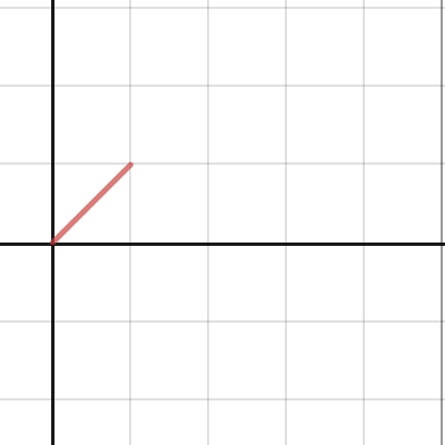
ph64 = ph * morph;
ph = ph64 % 4294967296;
does anyone know how i can optimize this
so i dont have to use a 64 bit int and modulo
it is very processor intensive rn
This is effectively what i am doing, where ph is x, and morph is a
Desmos
vivid rock
@storm harness "Unsigned integer arithmetic is always performed modulo 2^n
where n is the number of bits in that particular integer. E.g. for unsigned int, adding one to UINT_MAX gives 0, and subtracting one from 0 gives UINT_MAX": https://en.cppreference.com/w/cpp/language/operator_arithmetic
thus, you should be able to use
uint32_t ph;
...
ph=ph*morph;
I just tried this and it seemed to behave like saturated multiplication (i think that is the word)
it basically just maxed out
and didnt loop back round
vivid rock
did you declare ph as uint32_t?
storm harness
as a float
vivid rock
that is probably why... then ph*morph has type float
storm harness
so should i try (uint32_t)(ph * morph)
vivid rock
that should work
not sure if it really makes it faster than what you had originally
storm harness
I will see if i can get any improvement from doing it
It is running at audio rate so speed is pretty important
north stream
It's just modulo 2^34, so you can "and" it with 2^34-1, which can be done in chunks
vivid rock
2^32
vivid rock
I do not think there is any way to avoid using a 64 bit integer
vivid rock
the only question is what is faster:
ph=ph64%4294967296;
or
ph=ph64 & 0xFFFFFFFF;
(hope I correctly counted the number of Fs)
vivid rock
or just
ph = (uint32_t) ph64;
(the complier might throw a warning that this could lead to truncation and data loss)
obtuse spruce
If you are looking for fast, and audio rate... float is suspicious. Are you sure you need float? Depending on the processor you're on, this could be very expensive.
obtuse spruce
Okay- so you get float for cheap
In general, it is often the case that audio algorithms try either do things all in fixed point, or all in float if they have the FPU (you do). Skipping back and forth is often expensive.
storm harness
yeah i have been trying to stick to fixed point, but for this i couldn't really see a way to do it nicely without float
obtuse spruce
you can use fmod to stay in floating point.
storm harness
hm im not familiar with fmod
obtuse spruce
it's just % for floats: fmod(x, y)
Mind you, if you were doing your signal path in float, you'd probably normalize so that signal 1.0 is indeed 1.0f (rather than 2^32) - and then you just have ph = fmod(ph * morph, 1.0f); or even easier: ph = trunc(ph * morph);
(note: the above assumes #include <cmath> -- if you prefer #include <math.h> then you need to use fmodf and truncf)
storm harness
yeah i only have a few bits in float right now (mostly the stuff which is user controllable) but fmod will definitely come in useful as i am currently using floor() and ceil()
on a few different functions
obtuse spruce
On the other hand, if morph is a 32 bit value, with 16bits of fraction ... then ph = (uint32_t)((uint64_t)ph * (uint64_t)morph >> 16);
 median bay
Assuming that I hook up a hc-05 which will be pairing to a different hc-05 device, and another hc-05 using softwareserial- both onto the same Pro Micro, is it possible to transfer the data from the first hc-05 to the one using softwareserial via a global variable or some other method?
cedar mountain
Yes, you'd just have loop code which continually reads from one serial and writes to the other, and vice-versa.
lusty mountain
Got one of these things. Can it be used as a direct replacement for a set of buttons?
I bought it with the purpose of moving some buttons off a breadboard and cleaning up my project, but it seems to use different programming than the buttons
north stream
@lusty mountain Yes, I think it's just 4 switches with a shared common lead on one side and individual leads on the other. If your set of buttons can have a common lead (many setups can), that should work fine.
 wooden girder
hello. I'm trying to replace the lost remote controler of an old Philips MCM240 radio/cd player. I found some infos, like the part number of the remote controler, the protocol used (RC5), and controltower sent me the 4 codes I needed to turn radio on and control volume. but I don't understand how to use those codes. I tried with IrScrutinizer but it failed... any hint to help me connect the dots ?
(I'm trying to use an arduino nano with a IR led, of course)
 reef ravine
@wooden girder is your IR LED around 940 nm?
wooden girder
I took it from an universal remote controler, I guess it works well
I still have to test it but my problem is not yet there
reef ravine
should be OK, the receivers have a fairly good optical bandpass
are you using a lib or something? the codes need to be modulated at about 38KHz
wooden girder
I just discovered a newer lib than the IRremote one, that manage the RC5 protocol
and what I received from controltower was
function: POWER TOGGLE

code1: sendir,1:1,1,36000,1,1,32,32,32,32,32,32,64,64,65,33,32,32,32,32,32,65,32,32,64,32,32,3266

hex code1: 0000 0073 0000 000B 0020 0020 0020 0020 0020 0020 0040 0040 0041 0021 0020 0020 0020 0020 0020 0041 0020 0020 0040 0020 0020 0CC2

code2: sendir,1:1,1,36000,1,1,32,32,64,64,64,64,64,32,32,32,32,32,33,64,32,32,64,32,32,3262

hex code2: 0000 0073 0000 000A 0020 0020 0040 0040 0040 0040 0040 0020 0020 0020 0020 0020 0021 0040 0020 0020 0040 0020 0020 0CBE```I'm reading, but any hint to input that in IrScrutinizer is welcome
reef ravine
I'm loading the IRScrutinizer now, this topic comes up on my day job from time to time, I'd like to understand as well 🙂
reef ravine
Column 4?
reef ravine
not sure what you mean by columns in IRScrutinizer
when i drop the codes above in it appears to correctly detect that it is RC5 and device type 20
wooden girder
I use import/text-csv form
ok I didn't get how it works, I think I get it now
and the parameters I'm looking for are just here... wonderfull
reef ravine
I'll have to experiment further, glad it's giving you what you want
 tawdry flint
I have a problem with using DHTest and the DHT22 sensor
This was all working earlier today but now it stopped working.
#include <DHTesp.h>
DHTesp dht;
int dhtPin = D4;
dht.setup(dhtPin, DHTesp::DHT22);
With this I get the error 'dht' does not name a type. Why would this be? I am making an instance of the class above but then the setup method doesn't work. I have not used arduino that much yet.
The weird thing is that if I later call dht.getTemperature(); that I do not get an error (but it does return a nan value).
I also tried re-installing DHTesp but that did not help
reef ravine
what board are you using?
tawdry flint
esp8266
reef ravine
what happens when you try the example? https://github.com/beegee-tokyo/DHTesp/blob/master/examples/DHT_ESP8266/DHT_ESP8266.ino
tawdry flint
oh yeah
Ok yes I just copied the code with the right pin it now gives
OK 58.1 21.7 71.1 21.4 70.6 🥳
So I must be doing something wrong
reef ravine
now you have a reference point anyway, make small changes and see where it crashes
tawdry flint
Yeah I he is defining dht.setup(D5, DHTesp::DHT22); in void setup() I am defining this in a different file that might be it
tawdry flint
reef ravine
now you have a reference point anyway, make small changes and see where it crash...
But I should atleast be able to get it working now!
Trying the example is a good idea!
I was just scared that the example was not going to be of my board or something
Thanks!
wooden girder
reef ravine
I'll have to experiment further, glad it's giving you what you want
I got it working now, thanks for helping. It's good not to feel alone when stuck 🙂
tawdry flint
wooden girder
I got it working now, thanks for helping. It's good not to feel alone when stuck...
Yes this is so true
 half totem
hey quick question arduino is wirtten in C++ right
 gilded gazelle
 fleet sand
Hello, I have a task from the fingerprint scanner to upload the image to the server.
Now I have a scanner similar to ZFM-20 or AS608 and Arduino UNO.
The standard Adafruit-Fingerprint-Sensor-Library does not have an image upload function. I've finished writing it and now I'm getting some data, but I still can't figure out what format it's being uploaded in.
Could you help either with a scanner that can upload the image itself in some common format, or help with decoding the current data.
are there any similar projects\stories similar to mine?
obtuse spruce
@fleet sand - Let me see if I understand: You want to use the 0x0a and 0x0b commands to transfer images to/from the sensor device itself. The image data, according to the google-translated-spec-sheet is going to be 256px x 288px, 4 bit grey scale, packed two pixels per byte. In addition, communication with the device is packetized 64 bytes of data at a time so the 36,864 bytes will be transferred over several packets (there is an indicator in each packet to show if it is the last one.) I think the writeStructuredPacket and getStructuredPacket methods will help you here.
 sinful saffron
I cannot seem to get the DMXSerial library to work with an Arduino Mega ( https://github.com/mathertel/DMXSerial ). I see data/bits coming from the output pin of the board via an oscilloscope but the library doesn’t appear to pick that data up. I’m using an Arduino Mega and have altered the .cpp file to include " #define DMX_USE_PORT1 “ ( http://mathertel.blogspot.com/2013/05/update-for-dmxserial-library.html ) and have connected the output of the board to RX1 on the Mega. Is there something else I have to do in the code, or change in hardware? (I was able to check to see if the Arduino is/was seeing high low signals via the onboard LED with a simple test program as well).

GitHub
An Arduino library for sending and receiving DMX packets. - mathertel/DMXSerial
Blogging about Arduino software and hardware.
fleet sand
@obtuse spruce Yes, we are using 0x0A command, but for now when i using getStructuredPacket my arduino goes to restart loop, but sometimes its gets only one packet and then nothing. That blowing up my brain. Why is this happening? (Other, simple sketches work fine)
Im attaching the code just in case.
obtuse spruce
@fleet sand You aren't giving it enough data buffer --- and probably over running it:
Try this:
uint8_t data[256];
I don't know how long the data packets can be... I think only 64 bytes
ERRRR - never mind that --- Adafruit_Fingerprint_Packet has it's own data buffer.
when you get one packet - what does your code print on Serial? (Both the code you have in your .ino file, and the debugging code you inserted into the library)
tawdry flint
Hello this might be a noob question but I am running the TSL2591 Digital Light Sensor from adafruit with an esp8266. I think I connected the wires right but when I run the example I only get readings of 0. This might be because the pin numbers are not right so it might not be reading from the right inputs but in the example there is nowhere where you can change the pins it is reading from. So does anyone maybe have any experience with this sensor and the esp8266?
The sensor has the input pins of power and ground I got those right probably.
Then there is a pin on the sensor called SDA the guides said to connect this to I2C clock or the SCA on the board. The pictures of the pin out said that D2 was SCA so I connected that to D2
And there is a pin called SCL the guides said to connect this SCL on the board. The pictures of the pins of the ESP8266 said that D1 was SCL so I connected that to D1
With the example runs but the readings say 0 😦
I am a bit confused why I don't have to say to which pins I connected the sensor. How does the library know? Does anyone maybe have any tips? thanks
 safe shell
The library assumes the default I2C pins for SDA & SCL, there may be optional parameters if you are using non-standard pins. SDA is data, SCL is clock. They are typically on pins 4 and 5, though different boards may label them differently. You may have them swapped. See for example, https://randomnerdtutorials.com/esp8266-pinout-reference-gpios/.
sinful saffron
https://www.arduino.cc/en/reference/wire have to also #include <Wire.h>
Open-source electronic prototyping platform enabling users to create interactive electronic objects.
tawdry flint
sinful saffron
https://www.arduino.cc/en/reference/wire have to also #include <Wire.h>
Thanks the example does have this
tawdry flint
safe shell
The library assumes the default I2C pins for SDA & SCL, there may be optional pa...
Ok I will look into that
safe shell
This site says SDA is D1 and SCL is D2 https://diyprojects.io/getting-started-i2c-bus-arduino-esp8266-esp32-wire-library/, so maybe they are swapped
sinful saffron
some other boards are even different, like the Yun, I tried to do a drop in replacement to find it was a different set of pins than the Uno
safe shell
This site says D1 is SCL https://randomnerdtutorials.com/esp8266-pinout-reference-gpios/ 🤷
tawdry flint
safe shell
There was a note on the Adafruit ESP8266 Huzzah page that different chip versions changed the 4 & 5 assignments, so that could account for the different answers around the internet
What specific 8266 are you using? Did you try swapping the SDA & SCL wires (it won't hurt anything)?
safe shell
Do you have another I2C device you can try to verify the I2C pins? If that works, then I'd focus on the sensor.
sinful saffron
different default address maybe?
tawdry flint
safe shell
Do you have another I2C device you can try to verify the I2C pins? If that works...
This is the first thing I am ever working on I bought more sensors but I that might be another rabit hole
tawdry flint
sinful saffron
different default address maybe?
Perhaps, I was thinking this aswell but it is not really clear to me how I change it
sinful saffron
tawdry flint
So the board setting is actually on this
safe shell
The Adafruit breakout is address 0x29 . Are you using the Adafruit library? https://github.com/adafruit/Adafruit_TSL2591_Library
safe shell
can you post a photo of your hardware, showing the soldering and wiring?
(you should get errors if not connected properly, but...
tawdry flint
I did have to change the Serial.begin(9600) to 115200
safe shell
yeah, it just has to match whatever you are using for your serial console
tawdry flint
ok that makes sense
tawdry flint
sinful saffron
https://playground.arduino.cc/Main/I2cScanner/
Running this test gave me:
Scanning...
No I2C devices found```I am getting a picture
sinful saffron
not sure but it might be possible to set the pins: Limitations of the Wire.h library for ESP32 and ESP8266
Adapting the Wire.h library for ESP32 and ESP8266 development boards does not allow assigning an address to secondary equipment. We cannot therefore create an I2C network to communicate several ESP32 or ESP8266 together.
However, the SDA and SCL pins can be specified. Here, for example, pins 21 (SDA) and 22 (SCL) are manually assigned to the I2C bus by calling the method like this Wire.begin(pin_sda, pin_scl) .
Wire.begin(21,22);
tawdry flint
tawdry flint
sinful saffron
not sure but it might be possible to set the pins: Limitations of the Wire.h lib...
Where did you read this?
sinful saffron

Get started with the I2C bus with Arduino code examples. Pin identification, possibilities and limitations of the Wire.h library for ESP32 and ESP8266
safe shell
it's hard to tell from the picture, but are the breakout pins soldered to the headers?
sinful saffron
I'd also recommend doing the minimal number of connections for testing
safe shell
e.g., no need to run two yellow wires through the power rail, just connect directly for testing with one I2C device
tawdry flint
So first I tried to set it to 21,22 that gave a bunch of address not found messages
Then I tried Wire.begin(D2,D1); and it still said no ic2 found
tawdry flint
safe shell
e.g., no need to run two yellow wires through the power rail, just connect direc...
I tought as it was some sort of clock I needed to connect it to other sensors later
sinful saffron
it would just be a number
safe shell
oh
you really need to solder the breakout... it will not have good electrical connection
tawdry flint
I thought that if I just sort of pressed it it would be fine
sinful saffron
ah, yeah, definitely going to need to solder
tawdry flint
Ok
sinful saffron
also, the header should be below
 pulsar junco
tawdry flint
I thought that if I just sort of pressed it it would be fine
pulsar junco
tawdry flint
I thought that if I just sort of pressed it it would be fine
Also your pins are on wrong, make sure to fix htem before soldering
tawdry flint
With the black thing on the bottom of the sensor?
safe shell
sinful saffron
^
gray holly
Can someone help me with this sketch? It's kind of big. It worked fine once and then after that none of the neopixel would turn on
The lights work fine with a sketch for testing leds
obtuse spruce
why is your loop() written in that inverted form with all the lastXxxx globals?
pretty sure that is why nothing is happeneing.
 frosty finch
Hello there !
I have a problem with my HC-06. When I want to connect him with my phone, the red led continues flashing. If this has ever happened to you, can you help me ?
Thanks for your answers 🙂
 lone ferry
@frosty finch What phone do you have?
frosty finch
@lone ferry I have a Huaweii P30
lone ferry
Don't know about that one. (Not all phones can connect to a HC-06.)
frosty finch
I will buy a new HC-06 to maybe see a change...
frosty finch
lone ferry
Don't know about that one. (Not all phones can connect to a HC-06.)
I discover the problem It was the fact that I don't connect my phone with an application
Thanks for your fast answer 🙂
gray holly
Is there a way to simulate a button press to a certain data line?
pulsar junco
Depends on what you mean but you could drive the line hi or low?
 hexed agate
Does anyone know if I can check a pin def is an adc?
pine bramble
which target board
pine bramble
The SAMD series has 'variant.cpp'
metro M0, Linux:
$ egrep ADC ~/.arduino15/packages/adafruit/hardware/samd/1.6.3/variants/metro_m0/variant.cpp | egrep -v "No_ADC"
I am doing it in code
I did find this digitalPinHasPWM()
and NUM_ANALOG_INPUTS, but nothing exactly I can use hmm
pine bramble
I use vendors who document thoroughly.
Adafruit carries an ESP8266 breakout:
https://learn.adafruit.com/adafruit-huzzah-esp8266-breakout/pinouts
No ADC out, one ADC input, if I'm reading correctly.
safe shell
(8266 ADC limited to <1.0v)
pine bramble
ADC out is DAC iirc. ;)
hexed agate
LOL, I am checking a pin definition to determine if it is a digital or analog pin, IN code
It looks like I will be stuck with a custom solution per ic, esp32 has an ANALOG pinmode def, and esp8266 only has 1 so checking the pinmask might work, mode returns FFFFFF
pine bramble
Once you find out how it's coded in the board support package, you can (then) automate (somewhat) if your code is to assume there's an ADC input pin or not, and where it gets assigned and all that.
hexed agate
Yeah it will be board specific, not seeing anything in arduino level that will help
oh well
pine bramble
The AVR series isn't supported using the same structures (no variant.cpp for example).
I usually download all the development software, the recursively search for terms I'm interested in, and try to get a feel for some kinds of problems that way.
 $ cd ~/.arduino15
 $ ag ADC
something along those lines.
obtuse spruce
@hexed agate - you can use PinDescription and g_APinDescription[] in WVariant.h Adafruit and Arduino cores have this --- not sure if it is everywhere.
bool isPinAnalogCapable(int pin) {
  return g_APinDescription[pin].ulPinAttribute & (PIN_ATTR_ANALOG | PIN_ATTR_ANALOG_ALT);
}
or perhaps
bool isPinAnalogCapable(int pin) {
  return g_APinDescription[pin].ulPinType == PIO_ANALOG;
}
These will, however answer the question about the pin, as numbered by the Arduino Wiring core lib. -- and about how that core lib. assigns functions.
stuck coral
Has anyone happened to upload a custom sketch to the Metro M4 airlift coprocessor? The guide for updating firmware uses a precompiled bin for WiFiNINA and if I compile a .bin using the Arduino IDE and upload to the ESP32 I get the following from the ESP32 debug boot text-
invalid header: 0x4008fc66
invalid header: 0x4008fc66
...
Which I assume means I placed the BIN at the wrong address and misunderstand something
stuck coral
Lol, figured it out python3 -m esptool --chip esp32 --port /dev/ttyACM0 --before no_reset write_flash -z --flash_mode dio --flash_freq 80m --flash_size detect 0xe000 /home/samuel/.arduino15/packages/esp32/hardware/esp32/1.0.4/tools/partitions/boot_app0.bin 0x1000 /home/samuel/.arduino15/packages/esp32/hardware/esp32/1.0.4/tools/sdk/bin/bootloader_dio_80m.bin 0x10000 /tmp/arduino_build_509286/esp32_coprocessor_ovule_dev.ino.bin 0x8000 /tmp/arduino_build_509286/esp32_coprocessor_ovule_dev.ino.partitions.bin
gray holly
My arduino nano keeps getting the avrdude error and clicking the reset button does nothing
Only one green light is on
stuck coral
avrdude is the program on your computer that uploads the firmware what is the error exactly? Usually the issue is a bad USB cable
gray holly
it says avrdude out of sync
I'm loading the ide now
avrdude: stk500_recv(): programmer is not responding
avrdude: stk500_getsync() attempt 1 of 10: not in sync: resp=0x00
stuck coral
Yep, it cannot connect to the board
gray holly
Is the board broken? Usually I see multiple green and red lights but here there's just one green light
stuck coral
Probably not, is this a new board?
stuck coral
And is the red led doing something? Like blinking
gray holly
the reset button does nothing, it usually flashes a red light when I press it
nothing
just solid green
stuck coral
There is a red and a green right? The green is solid, what does the red do?
gray holly
red is off
stuck coral
It only comes on for a moment on reset?
gray holly
stuck coral
It only comes on for a moment on reset?
it usually does that but not anymore
stuck coral
Hm, where did you buy the board?
stuck coral
Hm, have you tried a different USB cable or USB port?
gray holly
I've tried different ports and made sure to click the right serial
let me get a different cable
stuck coral
Now when you say right serial, do you see multiple that shouldnt be there anymore?
gray holly
There's a port that disappears if I unplug the board, so I use that one
stuck coral
Okay, hm, Im thinking you are having a bootloader issue, normally the bootloader is locked, but the cheap boards from china sometimes dont lock it.
stuck coral
gray holly
I have old atmega bootloader selected
What do you mean by that?
stuck coral
gray holly
on the ide
That doesnt do anything unless you press burn bootloader, you could have accidentally over written a section of bootloader which would cause this issue
stuck coral
gray holly
So I should get a new bootloader?
Yep. But you need another arduino or a ISCP device
stuck coral
It would with ARM micros, I have not tried with an old AVR
Maybe someone else here can answer about that
It should
gray holly
Is it hard to do?
stuck coral
Not really, just time consuming
pulsar junco
gray holly
I would screenshot but I can't screenshot menus
Are you on windows? If so there's a neat trick with the screen cap tool, you can set a delay which should let you get into the menu before freezing the screen
gray holly
I'm using linux mint
pulsar junco
ah gotcha
stuck coral
gray holly
I'm using linux mint
Have you uploaded a sketch on that install before? You have permission to use the serial device?
gray holly
stuck coral
Have you uploaded a sketch on that install before? You have permission to use th...
I've succesfully uploaded sketches and run them before
I've run blink and controlled led strips
So I need another arduino?
stuck coral
You just need to flash a new bootloader, sadly that Arduino and the UNO are a pain
gray holly
but I need another board to flash it?
stuck coral
Either that or figure out how to use the pi
stuck coral
A breadboard just helps you make connections, Im not sure why you would need it as long as you can wire it up without the breadboard
gray holly
is mine real or a clone
stuck coral
A clone
gray holly
bruh I got tricked into buying a knockoff
stuck coral
Not really, it doesnt state its genuine
The logo isnt on the board
That is really common
gray holly
why does arduino let people make knockoffs
stuck coral
Yes, its open source hardware, you can make your own if you want, you are just not allowed to put the genuine arduino logo on the silkscreen
stuck coral
More clones, made by Geekstory
gray holly
Are clones lower quality?
stuck coral
If you shop by price, yep
gray holly
Do they work differently?
stuck coral
There are nice clones, but if you buy the cheapest boards you can they probably wont be great. And most are exact clones
Some differ slightly but will function the same
gray holly
Do you think geek story is good?
stuck coral
For instance, I have MEGAs that can switch between 5V and 3.3V IO. And idk, never bought from them
gray holly
my dad is not gonna like this
 woeful gorge
sorry if this is a dumb question, I'm new to arduinos and have very little knowledge of C+, I know more about python but obviously that doesnt help here. Is there anyway I can base an if statement off of an output, for instance, lets say I have a motor i want to control and an LED, could i say; if(Motor==HIGH){digitalWrite(LED,HIGH)}?
rough torrent
woeful gorge
sorry if this is a dumb question, I'm new to arduinos and have very little knowl...
Almost got it correct, Motor in your statement would be digitalRead(Motor) and there would be a semicolon after digitalWrite(LED, HIGH) so it would look like this:
// in your loop function
if (digitalRead(Motor) == HIGH) { // assuming Motor is a number which is the pin number the input is connected to
  digitalWrite(LED, HIGH) // assuming LED is a pin number
}
But motors are generally output devices, so I'm not sure what you mean by Motor, so I'm assuming it's a pin number that provides an input.
woeful gorge
not exactly, im using the motor as an output, i just want it to be where if the motor is on, so is the LED
oh im kinda dumb, i would just turn them both on and off at the same time, I havent really gotten good with inputs yet, im just starting, so im literally just going through basic stuff like using variables and turning things on and off
rough torrent
To check the blatantly obvious:
- Correct board?
- Correct port?
- Arduino is actually plugged in?
- Nothing attached to pins 0/1?
 green heath
I need a tip with my electronics. Ive wired up an ATmega to a programmer. the problem is I want to feed it with 3 AA batteries. but the programmer wont recognize the device when it runs with less than 5 volt (the batteries read 4.26)
thus I am feeding it with the programmers 5 volt. but the way its wired up right now is probably a bit dangerous as there is nothing seperating the voltage sources and I dont want to mess up the AVR or my laptop
how can I best solve that issue
north stream
I'd probably use steering diodes to separate the power supplies. Probably Schottky diodes for low voltage drop, or MOSFETs configured as diodes.
 frank linden
Another option I have seen are USB isolators. I personally have not used one but if I remember correctly, this was the challenge they were hoping to resolve.
green heath
well the other option is providing a stable 5 volt source. I am also trying to run a stepper motor with 5v...
I am also getting this error when I run the command as a bat file
the command otherwise works fine through the console
okay nevermind. something weird happened and it wasnt using the correct dash...
 shadow marlin
woeful gorge
oh im kinda dumb, i would just turn them both on and off at the same time, I hav...
shadow marlin
woeful gorge
oh im kinda dumb, i would just turn them both on and off at the same time, I hav...
Using variables is exactly right. In this case you would use a variable to keep track of whether you wanted the motor on or off.
 pallid rose
Hello
woven mica
hello
pallid rose
I am looking to connect and Arduino and an PLC. What could be the best way?
An Arduino with sensors sends data via USB to a PC. But I don't know how to link the Arduino with an PLC
I am thinking about cables and other thinks like this because it's for an industrial machine
 gilded swift
@pallid rose this might help you get started
Using arduino to interface PLC and Computer?
 sacred ivy
To add to that: I would also look into Ethernet as most plcs have Ethernet on them. You may have to do some leg work PLC side though.
frank skiff
I'm not too familiar with i2C, but SPI. How would the entire message be formatted?
To turn the display ON
Im using Wire.h on the arduino
  // Turn on Display
  Wire.beginTransmission(DEVICE_ID); // Transmit to device at 0x3C
  //Wire.write(byte(0x00));            // Control Byte?
  Wire.write(byte(0xAF));            // Command to turn display ON
  Wire.endTransmission();
  delay(200);
Yes, yes, yes, and no
Should probably mention that before I started having problems, I did try to set pin 0 and 1 as output low
rough torrent
lusty mountain
Should probably mention that before I started having problems, I did try to set ...
Is it in the code? If so, maybe that's affecting the upload sequence.
lusty mountain
Yes
rough torrent
If it is, you should be able to use another Arduino as an ISP to upload code without using the serial stuff
lusty mountain
I'm worried that they might be set to low, and I can't change it because it's basically locked me out
Is there any way to erase the code from the arduino without using serial?
Lucky for me I already ordered another arduino, was just hoping I could get the project working before that comes in
rough torrent
lusty mountain
I'm worried that they might be set to low, and I can't change it because it's ba...
Most likely what happened
rough torrent
lusty mountain
Is there any way to erase the code from the arduino without using serial?
Not that I know off
You will want to see this guide: https://www.arduino.cc/en/pmwiki.php?n=Tutorial/ArduinoISP
Open-source electronic prototyping platform enabling users to create interactive electronic objects.
lusty mountain
Alright, thanks
 cosmic mango
hello, I'm looking for some help with reading and writing to a flash memory ic with SPI
 elder hare
with the ArduinoJson lib how would i get the "air_temperature" so i can print it out?
frank skiff
cosmic mango
hello, I'm looking for some help with reading and writing to a flash memory ic w...
Which IC?
cosmic mango
EN25T80
frank skiff
Check the datasheet but it says it supports either SPI modes 0 and 3
probably best to download the datasheet but there's all the instructions
frank skiff
void output(byte data)  {
  byte instruction = 0x02;

  digitalWrite(CS, LOW);
  SPI.transfer(instruction);
  SPI.transfer(0x00);       // 8-Bit part of address
  SPI.transfer(0x00);
  SPI.transfer(0x00);
  SPI.transfer(data);       // 8-bit data
  digitalWrite(CS, HIGH);
}
this is one i wrote for an SRAM chip
cosmic mango
so this would write to the start of the first page?
frank skiff
It's not very neat but you can see the (READ) instruction followed by 3 byte address and then the data
You'd have to adapt it a little
frank skiff
well since the first instruction is to write it would write that data
so its WRITE/READ
ADDRESS
DATA
cosmic mango
i see. and in my case, the instruction would be 0x03?
frank skiff
for READ yeah
cosmic mango
ok
frank skiff
I forget, is a page one byte?
cosmic mango
a page is 256 bytes
frank skiff
you've got to tell it which mode
because it'll expect a certain amount of data to write
cosmic mango
whats the difference between the modes?
frank skiff
theres 4 but its different combinations of clocking data on the falling or rising edge
but use either 0 or 3
cosmic mango
i set the mode with this? SPI.setDataMode(0);
frank skiff
yep
cosmic mango
ok. going back to the address thing.
in your example, you had
SPI.transfer(0x00); x 3
is that for the start of the memory?
what would be the address for, say, the 3rd page
frank skiff
honestly it would be easier to read as 0x000000
cosmic mango
wait, can we read one byte at a time, or do we need to read the entire page?
obtuse spruce
I'd suggest looking at the Adafruit SPIFlash library - even if it doesn't support your chip directly - it has full examples of all these operations.
frank skiff
Yeah much easier to just use a library
but it looks like it reads continuously
honestly i'd have to read the datasheet more but i've gotta go
cosmic mango
yeah i just saw that too, looks like I give it a start address and it just reads from there
frank skiff
i'd say make it easy on yourself and use a library
obtuse spruce
You generally read in more than one byte at a time - and you can write arbitrarily.... BUT - subject to the Flash erasing: You must erase a whole sector (set it all to 1s) - from that point you can write anyway you want... it the writes will only turn 1s into 0s.
cosmic mango
i'll have a look at that library
obtuse spruce
If the chip is "standard" enough - you can just use that library - supplying your own block of configuration info for the chip you are using.
cosmic mango
so after some fiddling around, everything I try to read is 0
even the manufacturer and device id
did i kill it? or is it more likely I am just doing something wrong
my code:
elder hare
anyone ever used the SD-Card slot on a TFT 2.5" LCD Touch Screen befor?
frank skiff
cosmic mango
so after some fiddling around, everything I try to read is 0
If you really want to write your own it would be worth combining the instruction and adress into one 32bit (unsigned) integer
Would reduce issues with leading zeroes as long as you format the message correctly
Youd probbaly need to use a combination of bitmasks and bitshifts
int input() {
  byte instruction = 0x03;
  int data = 0;

  digitalWrite(CS, LOW);
  SPI.transfer(instruction);
  SPI.transfer(0x00);       // 8-Bit part of address
  SPI.transfer(0x00);
  SPI.transfer(0x00);
  data = SPI.transfer(0x00);
  digitalWrite(CS, HIGH);
  return data;
}
This is how i wrote my read function
 turbid path
Is it possible to use the LIS3DH library with circuit playground express? I want to use the library instead of the circuit playground library for my current project.
gilded gazelle
make the var an array? guessing
lone ferry
x = arbdata[index + bl + tableOffset];
lone ferry
where x is the type of the thing inside arbdata.
lone ferry
Depends. What is the type of arbdata?
storm harness
int16_t
lone ferry
Then int16_t x = ... is how you'd write it. It's not a pointer but an int16_t value.
 dreamy minnow
hello! i tried adapting a code which puts an esp8266 into acces point mode, then starts a webserver in which you input wifi credentials, but this is my first go at using ap mode and a webserver, could anyone point me in the right direction? https://pastebin.com/kTNGMt25 please ping me as it's 6 am for me and i'm going to get some sleep. P.S. i am aware of the existence of wifimanger and the such, but i want to learn this side of things.
Pastebin
Pastebin.com is the number one paste tool since 2002. Pastebin is a website where you can store text online for a set period of time.
 sacred dagger
Does anyone knows how to code in assembly on Tinkercad? I wanna try to sort an array.
pine bramble
Really? Wow. That's very cool. Just heard about Tinkercat, like, yesterday.
Autodesk had a CAD program that fit on a single diskette in 1989 - we had a free copy at the computer store I worked in.
(It was more useful than Linux' dia) .. varkon in Linux excellent general parameter-driven CAD - haven't seen it in many years though.
There's freecad in Debian:
 proven mauve
Hey, I've got a question. I've seen pointers to classes before, like this:
  &midi01, &midi02};
uint8_t type = midilist[0]->getType(); ```
and they can be used to cycle through class methods in for loops, stuff like that. But now I've got a class....I can make a pointer to it...
AutoMap * singlePotMaps[] = {&cutOffPotMap, &resFreqPotMap, &LFOratePotMap, &LFOresPotMap}; But the issue is I can't figure out how to use it then, because instead of being a class.function() call, it's just a class() call to use the automaps, as in to use one you just call: cutOffPotMap(300);```
If it were cutOffPotMap.useMe(300); that would be easy, I would just add the -> to the pointer call in the loop...
I hope this makes sense with my phrasing...
lone ferry
What you do mean by "a class() call", @proven mauve
proven mauve
so, to use those AutoMaps, you create them/name them, but then they only really do one thing. So instead of
cutOffPotMap.doTheThing(300); it's just
cutOffPotMap(300);
If I needed to add the .doTheThing to the call, I have an example of how to do that with the pointer by using ->. But I don't know how to do it when there isn't
lone ferry
The class() syntax is used to instantiate the class, you can't do it afterwards. But I'd need to see the actual AutoMap code (but it's time to make dinner now).
 summer wave
sounds like they're used more like functions than classes. i don't recall much c++, can you just singlePotMaps[i](300)?
proven mauve
no, the compiler doesn't like that 😦
expression cannot be used as a function
I'm not sure how to go about googling this either, I lack the vocabulary
To give a clearer example, I could totally use this:
AutoMap resFreqPotMap(0, 1023, 20, 210);
AutoMap * singlePotMaps[] = {&cutoffFreqPotMap, &resFreqPotMap};
for (int i = 0; i < 2; i++) {
singlePotMaps[i]->doTheThing(300);
}```
But instead of the AutoMaps working by using cutoffFreqPotMap.doTheThing();, the work by using cutoffFreqPotMap(); after you initialize them. snow pier
Hello, i am using 2 arduinos, connected via Bluetooth to send sensor and button data to an other arduino with DMX-shield.
I got the problem, that i cant read incoming data on one of the arduinos, it seems to stuck.
if (ble.available()) { delay(5); String receiveMsg = ble.readStringUntil('\n');
works on one arduino pretty well.
But the other arduino cant read a incoming String, it dosent go into the "if"
Anyone worked with bluetooth and might help me a little?
summer wave
proven mauve
I'm not sure how to go about googling this either, I lack the vocabulary
i probably have the syntax wrong. the concept i'm thinking of is function pointers, maybe referred to as jump tables or similar. those might help narrow your searching.
proven mauve
I just found a method inside the library, .next(). It looks like I can reference that, and using the class() like that just processes a .next call 😀
lone ferry
Yes, you need to call next() it looks like.
proven mauve
But I really do appreciate the help, I'm going to look into those so I can research them more, I would like to understand this better
lone ferry
Although it does have an operator () so you can use it as singlePotMaps[i](value);
proven mauve
lone ferry
Although it does have an operator `()` so you can use it as `singlePotMaps[i](va...
the compiler gets upset at me over those lol
lone ferry
What does it say?
proven mauve
expression cannot be used as a function
lone ferry
What is the expression?
proven mauve
int atkVal = dualPotMaps[0](osc[oscSelect][ATTACK]);
lone ferry
What is the definition of dualPotMaps?
proven mauve
#define ATTACK_POT A5    // select the input pin for the attack/decay potentiometer
AutoMap atkPotMap(0, 1023, 25, 3000);  // remap the attack pot to 3 seconds
AutoMap dkyPotMap(0, 1023, 25, 3000);  // remap the decay pot to 3 seconds
#define RELEASE_POT A4    // select the input pin for the  sustain/release potentiometer
AutoMap relPotMap(0, 1023, 25, 3000);  // remap the release pot to 3 seconds
AutoMap susPotMap(0, 1023, 0, 255);  // remap the sustain pot to appropriate level
AutoMap * dualPotMaps[] = {&atkPotMap, &dkyPotMap, &relPotMap, &susPotMap};```
However, this is working as intended:
```int atkVal = dualPotMaps[0]->next(osc[oscSelect][ATTACK]);```Try AutoMap dualPotMaps[] = { ... } without the *
proven mauve
So, including the operator() definition in the class is what makes it so I can reference the instance without a method, and that's whats making it into a .next call? Like, operator() in any class will do that?
lone ferry
No, they had to implement that in the AutoMap class.
lone ferry
Yeah it's because you're turning them into pointers.
proven mauve
But, using ->next will totally work for me, I can add all these to the control detection loops I already have set up now instead of having to implicitly calling each one
lone ferry
And an array is also a pointer, so the array is pointers-to-pointers.
proven mauve
I just didn't want to edit the library to make it easy for someone else to do after me
lone ferry
If you wanted to use () the syntax is probably: int atkVal = (*dualPotMaps[0])(osc[oscSelect][ATTACK]); because you need to deference the pointer.
proven mauve
lone ferry
If you wanted to use `()` the syntax is probably: `int atkVal = (*dualPotMaps[0]...
Yes, this compiles and also works after uploading
Thank you very much, I'm going to do it that way so I can reference it later when I've moved onto other projects, I already have a reference for using -> 😀
I've always had trouble fully grasping pointers
@lone ferry yeah, I've got it added into the control loops now and it works perfect. Thank you again!
 loud horizon
Hello, I'm trying to work with simhub, and in earlier updates you were able to go to the arduino ide, but I'm unable to
 next jetty
Silly question... I note the arduino have multiple ground pins... is this a convenience thing or should they be used/distributed evenly? (or can I just use the one to my external circuit)
vivid rock
just a convenience thing
next jetty
thanks
somber burrow
whenever i unplug my arduino from the usb port just goes crazy, i dont really know how to explain it. I have it plugged into a 12v power supply because im controlling an led strip that used 12v but when i unplug the usb port the arduino doesnt work the same way it would if it was plugged in
anybody know why this is happenign?
pulsar junco
Maybe it's rebooting?
somber burrow
i think its a power problem
but i have no other power supplies or anything like that
so
pulsar junco
Oh i misread your post my apologies, in what way does it work differently?
somber burrow
it just freaks out
thats the best way to describe it
so i have an rgb strip that came with a 12v 3a power supply, and im just plugging that directly into the arduino. when i discornnect the usb the lights start flickering in unusual ways
pulsar junco
do they continue to flicker or does it go back to normal?
pulsar junco
hm
pulsar junco
does it flicker if you unplug everything and the plug in only the power supply?
somber burrow
ya
lemme try it again hold on
yeah it still does it
and it isnt like a constant flicker eitehr, random pulses
also random colors
somber burrow
if anybody finds a solution, ping me, imma sleep now lol
vivid rock
which arduino is it?
pine bramble
When you sequence two power supplies, one sequence is preferential to the opposite one.
If you power them in the wrong sequence, one supply will backfeed to the MCU in ways that will make it behave oddly.
So for example, I have an STM32F407 Discovery, an Adafruit CP2104 Friend, a Lumex 96x8 display, and a 5 volt 2A power supply.
Everything except the Lumex is powered through CP2104 which is fed by its USB connection to the host PC.
I always plug in the 5V 2A supply first, then the USB cable.
For disconnect, I disconnect the USB cable, then disconnect the 5V 2A supply.
(I bond the 5V pin of the CP2104 Friend to the 5V pin of the STM32F407 Discovery, so CP2104 board is powering the STM32 board and its MCU).
My solution (haven't tried it yet): add 10k resistors inline between TX (Lumex) and RX (STM32), and the mating wire (TX from STM32 running to RX on the Lumex board).
The idea is to current-limit any backfeeding happening via the TTL serial connections between the Lumex display and the MCU responsible for sending it messages in English. ;)
Ideally: a master power switch that engages all power supplies at the same moment.
That's what you have with commercial products, after all.
- -
The reason why sequencing is problematic: if you power your MCU properly, it will ignore 'backfeeding' via its port pins (as that will be weaker).
If you start the MCU with its port pins backfed some amount of current from elsewhere, then even though you've applied the correct power to it locally, it tends to be unreliable in how/if it starts up.
🛩️
somber burrow
vivid rock
which arduino is it?
arduino uno
somber burrow
pine bramble
If you start the MCU with its port pins backfed some amount of current from else...
ic, how do i fix it?
do i use a smaller supply?
pine bramble
@somber burrow Use a 10k resistor in series with a GPIO pin, if you're connecting to any of them. Try that.
Exception might be: lighting an LED with that pin. In that case, just use the regular current-limiting resistor.
somber burrow
yeah im using 9, 10, 11 to control the LED's
pine bramble
Those aren't where the backfeeding comes from as they don't interact with another powered device .. they are endpoints in themselves.
The problem is on communication lines to other MCU's.
somber burrow
im using A4, is that what you mean?
pine bramble
I don't remember things like that.
somber burrow
im not using any of the io pins besides those 3
pine bramble
Then that's not what's going on .. backfeeding requires a second voltage source.
(Only happens when there are more than one power supplies)
somber burrow
yeah, the problem isnt when im using mutliple power supplies, its when im only using one (the 12v 3a one)
pine bramble
Why are you using 12V?
somber burrow
thats the supply that came with the LED strip
pine bramble
Well you might need some isolation on the data line controlling that strip.
What's the logic/signalling voltage level on the input port for that strip?
pine bramble
Sorry, Discord Canary decided I had to upgrade.
somber burrow
all good lol
pine bramble
Okay if it's not individual then you're just PWM'ing for colors, right?
somber burrow
yep
pine bramble
You're driving transistors (BJT's or MOSFETS) right?
somber burrow
yep
pine bramble
And the MCU is acting flaky. Right?
somber burrow
pine bramble
You're driving transistors (BJT's or MOSFETS) right?

this configuration^
yeah it is
pine bramble
I thought you said it is reliable if you don't do <foo> but I don't remember what <foo> is.
somber burrow
it is reliable when it is plugged into my computer + using the 12v supply, it is not reliable when i am only using the 12v supply
somber burrow
yeah ig so
pine bramble
It's probably putting out enough hash to reset the micro occasionally, or cause it to glitch.
somber burrow
that makes sense, so do i need a new supply? or can i just add a capacitor for good luck lol
pine bramble
A few well-placed bypass capacitors could help.
If you get any consistent improvement by that method, you may be onto something with the noisy 12V PSU theory.
If you had a known clean 12 V PSU to substitute that could make things go faster.
(speed up troubleshooting)
somber burrow
ill look for one, but what is the reason for it working when i have it plugged into the usb port on my computer
shouldnt it be broken either way
pine bramble
I'm just guessing on that and don't have a clear idea going just yet.
The PC may simply be providing a path for the noise to be shunted to ground.
I'm just making this up since I'm not sure I understand enough of the problem.
somber burrow
imma look for another supply brb
pine bramble
Is everything on a single 120 volt AC electrical outlet?
somber burrow
yep
pine bramble
How is the 12V PSU grounded?
somber burrow
To the outlet
pine bramble
Yeah see I don't know if you can bond the minus lead of the 12V supply to the MCU or not.
Working without a schematic makes it difficult to spot obvious errors.
somber burrow
i dont have a drawn up schematic, what exactly do you need to see
thats teh supply im using
which goes to the arduino
pine bramble
Oh so you have a 12V PSU with a 2.1 mm plug on the end of it and are powering the Arduino Uno form factor target board, and your project only runs properly when the USB connection to the target is made.
It doesn't do anything wrong with the USB connection there?
pine bramble
What does it do wrong with the USB removed?
somber burrow
it flickers and stuff, i can send a video if you want
pine bramble
I was raised by wolves in fresh air and sunshine, so I'm not attracted to this 'video' magic you speak of.
somber burrow
lol
so basically the only way to explain it is that the board freaks out and does random things
no specific order
pine bramble
I like things that either don't move when you look at them, or that are apt to say hello to you (eventually) if they do move, when you look at em.
Random things like what?
somber burrow
pine bramble
Random things like what?
the lights on the board also flicker, including the rgb strip
the green and yellow ones
pine bramble
Yeah that doesn't sound very good. ;)
somber burrow
the green one is brighter than the yellow one
pine bramble
Sounds a bit systemic.
somber burrow
o so the mcu is broken u think?
pine bramble
Not at all. You said it works under USB + 12V
pine bramble
If you had 12VDC batteries (several D cells in series) that might clean it up.
pine bramble
Why would a thirty second test take all day?
pine bramble
I would program the Arduino to blink the strip on and off in an unpredictable pattern, to prove it's running under program control.
For example, have it count. 1 blink ; pause; 3 blinks ; pause ; 5 blinks ; pause ; 2 blinks ; pause ; 4 blinks ..
somber burrow
Gotta put these together first
pine bramble
Hehe I've used rolled up paper like from a copier machine, and some elmer's glue-all to make up some tight fitting D cell tubes.
Seven cells produce about 11.27 volts.
 $ dc -e '5 k 1.61 7 * p q'
11.27
You need to reduce the load the LED strip puts on those AA cells.
Probably the easiest way is to adjust them to super dim while the project is functioning (with USB connected and the old PSU).
D cells are not AA cells.
Even a set of D cells will be taxed pretty hard by even a moderately dimmed strip.
pine bramble
D cells are very large in diameter.
somber burrow
lol
pine bramble
Like near one inch in diameter.
pine bramble
At any rate see what you can do to dim the strip before you connect the batteries.
somber burrow
O yeah it says d cell on it lol
pine bramble
Yeah that's a D cell (or a C cell, I can't tell from here).
somber burrow
How many do I need?
pine bramble
What exactly did you spend your entire childhood on, that you don't know which batteries a given object needs to run? Every kid I knew learned which ones to steal and who had them in which appliance, to steal them from. ;)
somber burrow
Different times ig lol
pine bramble
Are they brand new batteries?
pine bramble
Assume 1.4 volts per cell and about 7 volts minimum.
Try five and see how it goes.
4x cells give 6.4 volts when new.
(roughly 1.6V per cell out of the package)
somber burrow
Small problem, only 3 of them actually work
pine bramble
haha.
Well try dimming the strip so it's very weak.
See if that improves the behavior at all.
pine bramble
You have to do that.
I don't have a schematic. So it's either the program (reduce the duty cycle) or the schematic (change the circuit).
You might be taxing your power supply.
Why did they provide a power supply?
somber burrow
i bought this and just took the led strips and the power suply
and the ir sensor, but thats not for this project
somber burrow
yes
pine bramble
How long did you own and use this system?
pine bramble
That's not a lot of time but at least you saw it working.
somber burrow
yeah every function on there works fine
pine bramble
That almost eliminates the PSU since the white box had a remote control that had to get power from that PSU (the 'listener' had to get power from it).
If that PSU was putting out serious noise it should have glitched the gadget inside that white box.
somber burrow
which it didnt
pine bramble
Maybe your connections aren't as free of intermittency as one might have assumed.
How did you physically connect things up?
somber burrow
btw the project itself is an audio visualizer, i have a 3.5 mm jack that is plugged into a circuit that amplifies it and uses an envelope detector, that goes into the arduino, then the arduino controlls the lights. thought that might be helpful
pine bramble
Yeah that's another physical connection.
Another source of backfed power and of noise.
somber burrow
lol it wont let me send in the photo because its explicit content
anyway, thats what the connections look like
pine bramble
Yeah that'd flicker. ;)
somber burrow
wait why??
somber burrow
but if that were the case, why does it work fine when i have it plugged into the usb
pine bramble
Maybe the MCU is held up by VUSB which is dependable.
You should be able to add a 5V LiPo with a USB-A jack in substitution for the connection to the host PC.
Like the ones sold to recharge your cell phone.
somber burrow
yeah that would work
except it would look funky
sacrifices i guess
cause this is my setup...
pine bramble
Right but it helps in troubleshooting to show that it does work.
pine bramble
I'd really have to inspect the solder joints visually to even guess if they're just fine or are going to be a problem.
somber burrow
I went through everything with a multimeter. Nothing is shorted
pine bramble
I'd also try pressing on different points to see if i could start the Arduino successfully, using that third arm that sticks out of my chest, and the tiny hand I have there.
Get like a 2x2 foot sheet of plywood and tape everything down so nothing moves at all.
Then just press on things until the behavior changes.
When you can't make it change after trying quite a few things it's probably stable.
(stable good or stable broken) ;)
somber burrow
pressing on things in the curcuit i made or in the mcu?
pine bramble
The soldering job you did and all cables connected to it.
somber burrow
just to be clear we are talking about pressing it with a multimeter in the diode mode thing